Embed Size (px)
Citation preview

This is a repository copy of The application of plastic flow theory to inelastic column buckling.
White Rose Research Online URL for this paper:http://eprints.whiterose.ac.uk/98705/
Version: Accepted Version
Article:
Becque, J. (2016) The application of plastic flow theory to inelastic column buckling. International Journal of Mechanical Sciences, 111. pp. 116-124. ISSN 1879-2162
https://doi.org/10.1016/j.ijmecsci.2016.04.005
Article available under the terms of the CC-BY-NC-ND licence (https://creativecommons.org/licenses/by-nc-nd/4.0/)
[email protected]://eprints.whiterose.ac.uk/
Reuse
This article is distributed under the terms of the Creative Commons Attribution-NonCommercial-NoDerivs (CC BY-NC-ND) licence. This licence only allows you to download this work and share it with others as long as you credit the authors, but you can’t change the article in any way or use it commercially. More information and the full terms of the licence here: https://creativecommons.org/licenses/
Takedown
If you consider content in White Rose Research Online to be in breach of UK law, please notify us by emailing [email protected] including the URL of the record and the reason for the withdrawal request.

1
THE APPLICATION OF PLASTIC FLOW THEORY TO INELASTIC 1
COLUMN BUCKLING 2
by Jurgen Becque1 3
4
ABSTRACT 5
6
The paper presents a theory of inelastic column buckling which is consistent with the 7
principles of plastic flow theory. The theory accounts for flexural, torsional and flexural-8
torsional modes. While the use of the tangent modulus to describe inelastic flexural 9
buckling has been common place for a long time, efforts to comprehensively unite the 10
torsional and flexural-torsional modes with the principles of plastic flow theory have so far 11
been hampered by the ‘plastic buckling paradox’. New theoretical developments presented 12
in this paper provide a way to achieve this goal. The solution hinges on the derivation of the 13
inelastic shear stiffness while considering an infinitesimal solid element embedded within 14
the column at a stage immediately past the point of buckling. 15
The proposed inelastic column theory is verified against selected experimental data 16
pertaining to aluminium and stainless steel columns of various cross-sections. Particular 17
attention is paid to the torsional buckling problem of the inelastic cruciform section column. 18
19
1Lecturer, Department of Civil and Structural Engineering, University of Sheffield, Sir 20
Frederick Mappin Building, Mappin Street, S1 3JD Sheffield, UK. Tel: +44 (0)114 21
2220252, [email protected] 22

2
1. BACKGROUND 1
2
With respect to inelastic flexural buckling of columns, Engesser (1889) was the first to 3
propose the use of the tangent modulus Et to predict the buckling load of an initially 4
perfectly straight, inelastic column by modifying Euler’s differential equation as follows: 5
6
0Pudx
udIE
2
2
t (1) 7
8
where u is the lateral column deflection, P is the axial compressive load and I is the second 9
moment of area of the cross-section about the principal axis about which bending takes 10
place. Eq. (1) results in an expression for the column buckling load: 11
12
2
e
t2
crL
IEP (2) 13
14
where Le is the effective length, dependent on the boundary conditions. 15
While straightforward, Engesser’s approach received criticism from Considère (1891) who 16
argued that, as the column starts to bend out laterally, elastic unloading takes place on the 17
convex side of bending and that consequently, the bending stiffness is not simply 18
determined by EtI. Engesser (1895) replied by proposing his “double-modulus” or “reduced 19
modulus” theory, where: 20
3
2
e
r2
crL
IEP (3) 1
with: 2
I
IE
I
IEE t
0
c
tr
(4) 3
Ic and It are the second moments of area of the parts of the cross-section subjected to 4
compression and tension with respect to the neutral axis, respectively, and E0 is the initial 5
elastic modulus. 6
It soon became apparent that Eq. (2) showed much better agreement with the experiment 7
than Eq. (3), which consistently led to overestimates. Shanley (1947) shed light on this 8
seeming paradox by pointing out that Eq. (2) does indeed constitute the buckling load of 9
the column since it indicates the point of bifurcation above which the column cannot be in a 10
state of stable equilibrium while remaining straight. Moreover, lateral buckling does not 11
take place under a constant load, but elastic unloading on the convex side instead results in 12
postbuckling capacity. 13
A realistic theory describing buckling of inelastic columns involving torsion, which may 14
either occur as pure torsional buckling or combined flexural and torsional buckling, based 15
on the principles of plastic flow theory has not yet been presented. The challenge thereby 16
lies in modelling the relationship between increments of shear stress and shear strain at the 17
onset of buckling. A previous interpretation of plastic flow theory (Hutchinson 1974, 18
Lubliner 1990, Bazant and Cedolin 1991) has suggested that the increments of shear stress 19
4
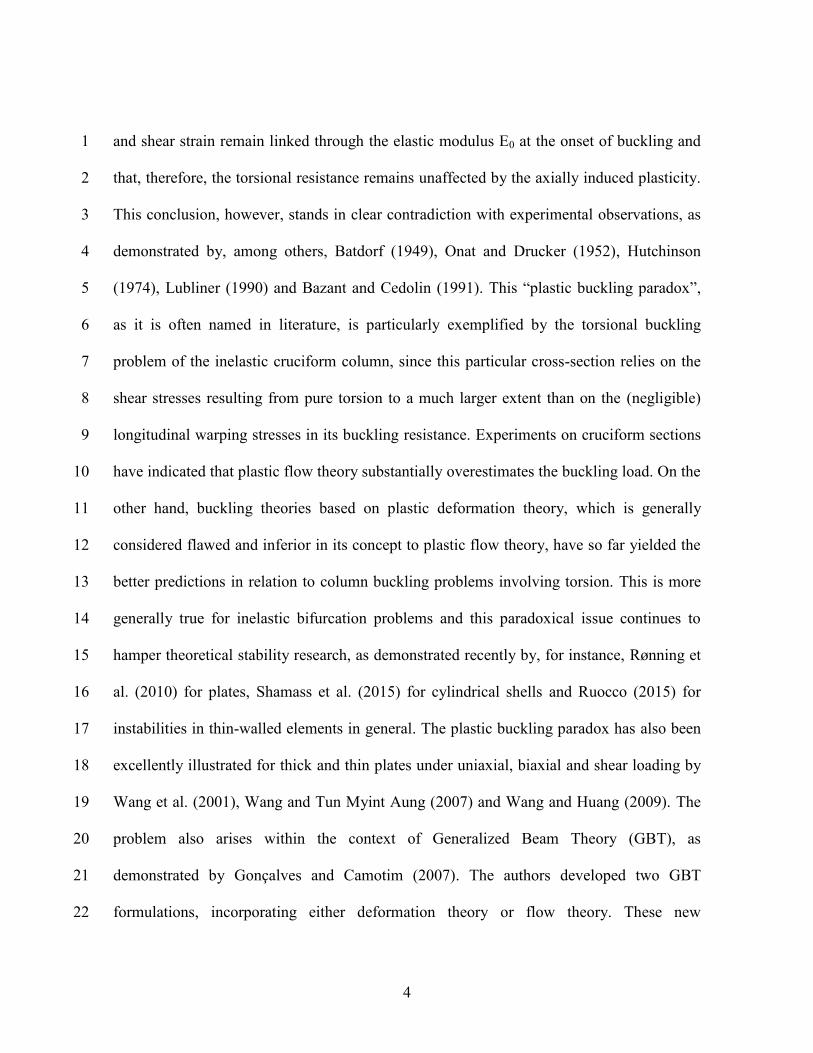
and shear strain remain linked through the elastic modulus E0 at the onset of buckling and 1
that, therefore, the torsional resistance remains unaffected by the axially induced plasticity. 2
This conclusion, however, stands in clear contradiction with experimental observations, as 3
demonstrated by, among others, Batdorf (1949), Onat and Drucker (1952), Hutchinson 4
(1974), Lubliner (1990) and Bazant and Cedolin (1991). This “plastic buckling paradox”, 5
as it is often named in literature, is particularly exemplified by the torsional buckling 6
problem of the inelastic cruciform column, since this particular cross-section relies on the 7
shear stresses resulting from pure torsion to a much larger extent than on the (negligible) 8
longitudinal warping stresses in its buckling resistance. Experiments on cruciform sections 9
have indicated that plastic flow theory substantially overestimates the buckling load. On the 10
other hand, buckling theories based on plastic deformation theory, which is generally 11
considered flawed and inferior in its concept to plastic flow theory, have so far yielded the 12
better predictions in relation to column buckling problems involving torsion. This is more 13
generally true for inelastic bifurcation problems and this paradoxical issue continues to 14
hamper theoretical stability research, as demonstrated recently by, for instance, Rønning et 15
al. (2010) for plates, Shamass et al. (2015) for cylindrical shells and Ruocco (2015) for 16
instabilities in thin-walled elements in general. The plastic buckling paradox has also been 17
excellently illustrated for thick and thin plates under uniaxial, biaxial and shear loading by 18
Wang et al. (2001), Wang and Tun Myint Aung (2007) and Wang and Huang (2009). The 19
problem also arises within the context of Generalized Beam Theory (GBT), as 20
demonstrated by Gonçalves and Camotim (2007). The authors developed two GBT 21
formulations, incorporating either deformation theory or flow theory. These new 22

5
formulations were then applied to the cases of simple plates under uniform compression 1
and hat section beams in uniform bending. It was concluded that the flow-based GBT 2
resulted in much higher predictions of the buckling stresses than the deformation-based 3
theory. 4
Interestingly, it has been observed (Shamass 2015) that the results of geometrically non-5
linear finite element analyses using flow theory with an associated flow rule are unaffected 6
by the plastic buckling paradox. While no explanation has yet been provided as to why an 7
incremental numerical approach remedies the problem, a firm conclusion can be drawn 8
from this observation, namely that the plastic buckling paradox is not due to any inherent 9
shortcomings or limitations of flow theory itself, but rather a result of an incorrect 10
application of its principles. This idea is central to the theory proposed in this paper. 11
Onat and Drucker (1953) demonstrated that the plastic buckling paradox can be 12
circumvented by incorporating imperfections into the model and that even very small, 13
inevitable imperfections have a severe impact on the buckling load, reducing it to levels 14
close to those predicted by deformation theory. Hutchinson and Budiansky (1976) 15
confirmed this finding for low strain-hardening metals. However, they also demonstrated 16
that for metals with significant strain-hardening the imperfections have to be of such 17
magnitude that they can no longer be considered ‘small and inevitable’, thus suggesting that 18
Onat and Drucker’s explanation is not entirely satisfying. 19
The approach presented in this paper differs from the aforementioned rationale in that a 20
perfectly straight column is considered, without initial imperfections. Instead, the plastic 21
buckling paradox is resolved by deriving a relationship between shear stress and shear 22

6
strain increments at the onset of buckling, while applying the plastic flow rule to a solid 1
element in its shear deformed shape. The basic principles of plastic flow theory, however, 2
are retained. 3
4
2. INELASTIC SHEAR STIFFNESS 5
6
An expression for the inelastic shear stiffness G1 of a non-linear metal is first derived, 7
accounting for the presence of a uniaxial compressive stress. G1 will be used in the 8
following paragraphs to relate increments of shear stress and shear strain at the point of 9
column buckling. The derivation here presented is a generalized and amended version of 10
the one contained in Becque (2010). 11
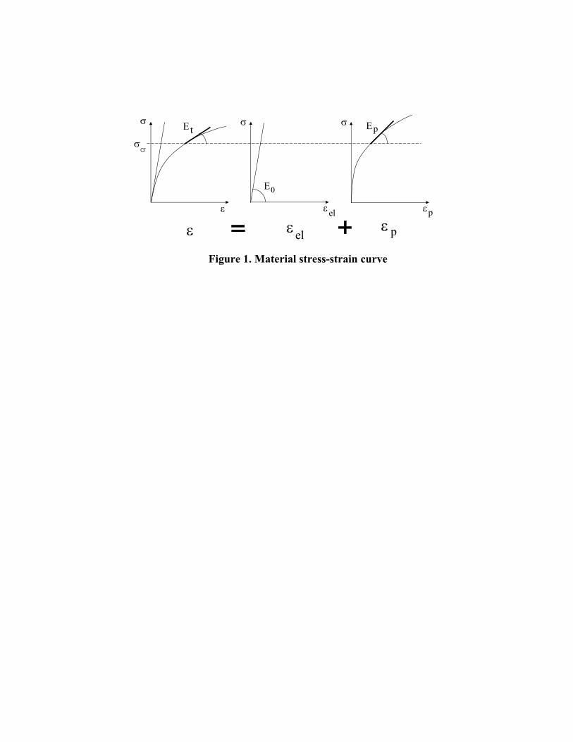
We consider the material stress-strain curve of a non-linear metal, as determined from a 12
uniaxial compression test (Fig. 1). It is a generally accepted postulate of plasticity that an 13
increment in axial strain 1 is composed of an reversible elastic component el,1 and an 14
irreversible plastic component p,1 : 15
16
p,1el,11 (5) 17
18
Eq. (5) can be written in terms of the increment in axial stress 1 associated with 1 : 19
20
p
1
0
1
t
1
EEE
(6) 21
7
1
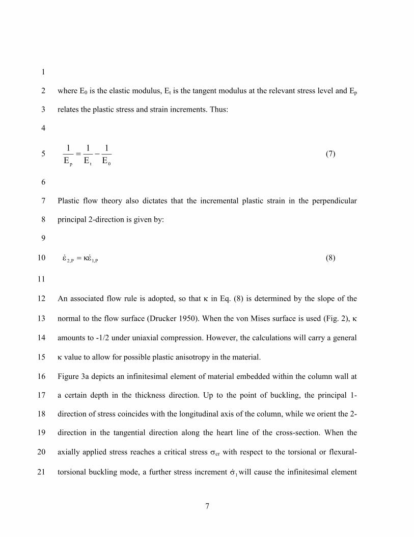
where E0 is the elastic modulus, Et is the tangent modulus at the relevant stress level and Ep 2
relates the plastic stress and strain increments. Thus: 3
4
0tpE
1
E
1
E
1 (7) 5
6
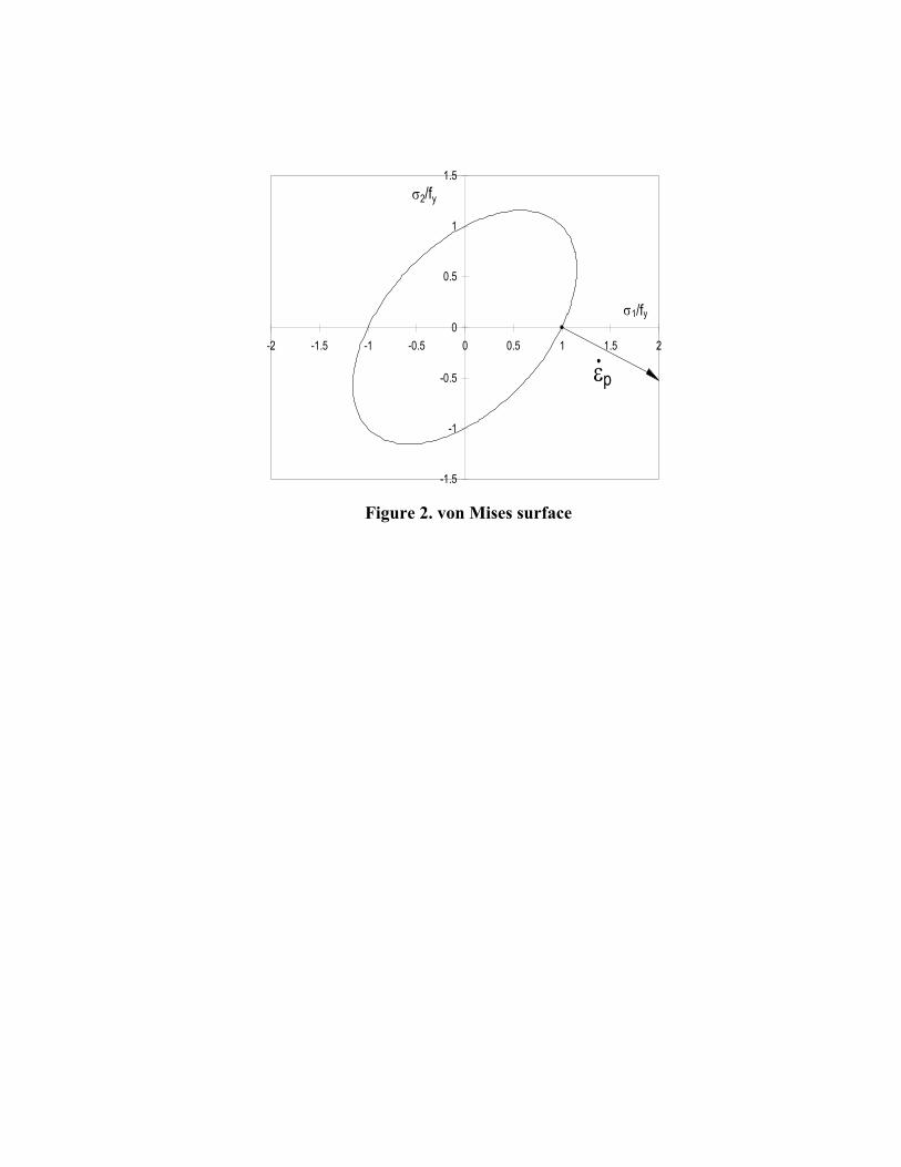
Plastic flow theory also dictates that the incremental plastic strain in the perpendicular 7
principal 2-direction is given by: 8
9
P,1P,2 (8) 10
11
An associated flow rule is adopted, so that in Eq. (8) is determined by the slope of the 12
normal to the flow surface (Drucker 1950). When the von Mises surface is used (Fig. 2), 13
amounts to -1/2 under uniaxial compression. However, the calculations will carry a general 14
value to allow for possible plastic anisotropy in the material. 15
Figure 3a depicts an infinitesimal element of material embedded within the column wall at 16
a certain depth in the thickness direction. Up to the point of buckling, the principal 1-17
direction of stress coincides with the longitudinal axis of the column, while we orient the 2-18
direction in the tangential direction along the heart line of the cross-section. When the 19
axially applied stress reaches a critical stress cr with respect to the torsional or flexural-20
torsional buckling mode, a further stress increment 1 will cause the infinitesimal element 21

8
to undergo incremental deformations in the 1- and 2-directions, as well as deformations in 1
shear characterized by the angles 1 and 2 in Figure 3a. The angles 1 and 2 are, in 2
general, different as the infinitesimal element may also undergo a rigid body rotation 3
relative to the direction of the axial stress in addition to its shear deformations. The load on 4
the column is thereby assumed to be a gravity load or similar to a gravity load in a sense 5
that it maintains its vertical direction in space as the column buckles. 6
It is noted that the classical formulation of flow theory does not predict any plastic shear 7
deformations to take place in this process (Hutchinson 1974, Lubliner 1990, Bazant and 8
Cedolin 1991). In other words, the incremental shear deformations are purely elastic. 9
However, this point of view can be dislodged by considering the infinitesimal plate element 10
in its deformed shape (Figure 3a) in combination with Mohr’s circle of the incremental 11
plastic strains (Figure 3b). For completeness, a few notes should be added. First, the 12
incremental plastic deformation in the thickness direction, p,3 , is non-zero. However, since 13
the 3-direction constitutes a principal direction and is also the axis of rotation of our 14
reference system, the use of Mohr’s circle is indeed justified. Second, plastic flow theory 15
dictates that the principal directions of the incremental plastic strains coincide with the 16
principal directions of the (total) stresses. At the point of buckling, infinitesimal plate 17
bending stresses and shear stresses develop. However, since these additional stresses are 18
initially infinitesimal, they do not affect the principal directions of stress. For the purpose of 19
considering the incremental step in Figure 3 immediately past the point of buckling, the 20
principal directions of stress (and thus of incremental plastic strain) remain firmly pointed 21
along the column axis and in the perpendicular direction within the column wall. 22

9
While the infinitesimal plate element in Figure 3a deforms, the sides a-a and b-b rotate 1
from their initial vertical and horizontal positions to final inclined positions at the end of 2
the load increment. At any stage during this transition, Mohr’s circle indicates the 3
magnitude of plastic shearing which occurs along a-a and b-b. It is clear that, while planes 4
a-a and b-b rotate, the instantaneous magnitudes of the shear strains along a-a and b-b 5
(which are initially zero) gradually increase. The total plastic strain increments need 6
therefore be found by incremental integration, where the total increment in principal plastic 7
strain p,1 is subdivided into a number of intervals dp 1,1 . The sum of the d ‘s 8
thereby adds up to 1 . In each interval the radius of Mohr’s circle is given by: 9
10
d
2
1R
1
p,1
(9) 11
12
Therefore, the total plastic shear strains along a-a and b-b at the end of the increment are 13
found as follows: 14
15
p,111
1
p,1
0 1
p,1
p,a2
112cos
2
1
2
1d2sin
2
11
(10) 16
p,122
2
p,1
0 2
p,1
p,b2
112cos
2
1
2
1d2sin
2
12
(11) 17
18
10
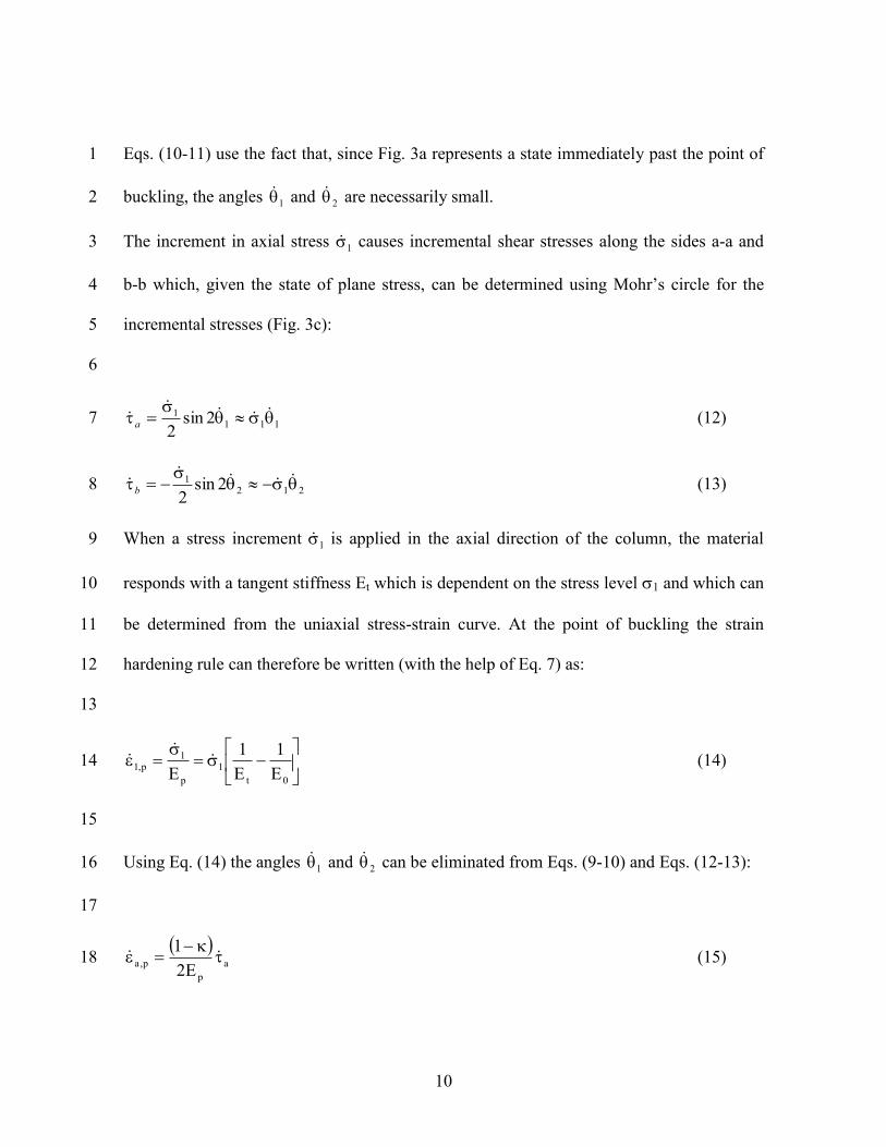
Eqs. (10-11) use the fact that, since Fig. 3a represents a state immediately past the point of 1
buckling, the angles 1 and 2 are necessarily small. 2
The increment in axial stress 1 causes incremental shear stresses along the sides a-a and 3
b-b which, given the state of plane stress, can be determined using Mohr’s circle for the 4
incremental stresses (Fig. 3c): 5
6
1111 2sin
2
a (12) 7
2121 2sin
2
b (13) 8
When a stress increment 1 is applied in the axial direction of the column, the material 9
responds with a tangent stiffness Et which is dependent on the stress level 1 and which can 10
be determined from the uniaxial stress-strain curve. At the point of buckling the strain 11
hardening rule can therefore be written (with the help of Eq. 7) as: 12
13
0t
1
p
1p,1
E
1
E
1
E
(14) 14
15
Using Eq. (14) the angles 1 and 2 can be eliminated from Eqs. (9-10) and Eqs. (12-13): 16
17
a
p
p,aE2
1
(15) 18

11
b
p
p,bE2
1
(16) 1
2
The constitutive equations (15-16) are independent of the angles 1 and 2 (within small 3
perturbations of the unbuckled state) and, by consequence, have to hold true at the point of 4
buckling itself. At this limit point, when the column is in an undeformed state (apart from 5
an axial shortening), the angles 1 and 2 are zero and the planes a-a and b-b in Fig. 3 are 6
perpendicular to each other. However, Eqs. (15-16) are still valid. In this undeformed state, 7
reciprocity of the shear stresses holds, and thus: ba , while the total plastic shear 8
straining can determined by adding Eqs. (15-16) (something which is, of course, not 9
possible in the deformed state): 10
11
p
p.bp.apE
1 (17) 12
13
The elastic shear strain is governed by the well-known equation: 14
15
0
elG
(18) 16
17
where G0 is the elastic shear modulus: G0 = E0/[2(1+)]. 18
The total shear strain increment is then given by: 19
12
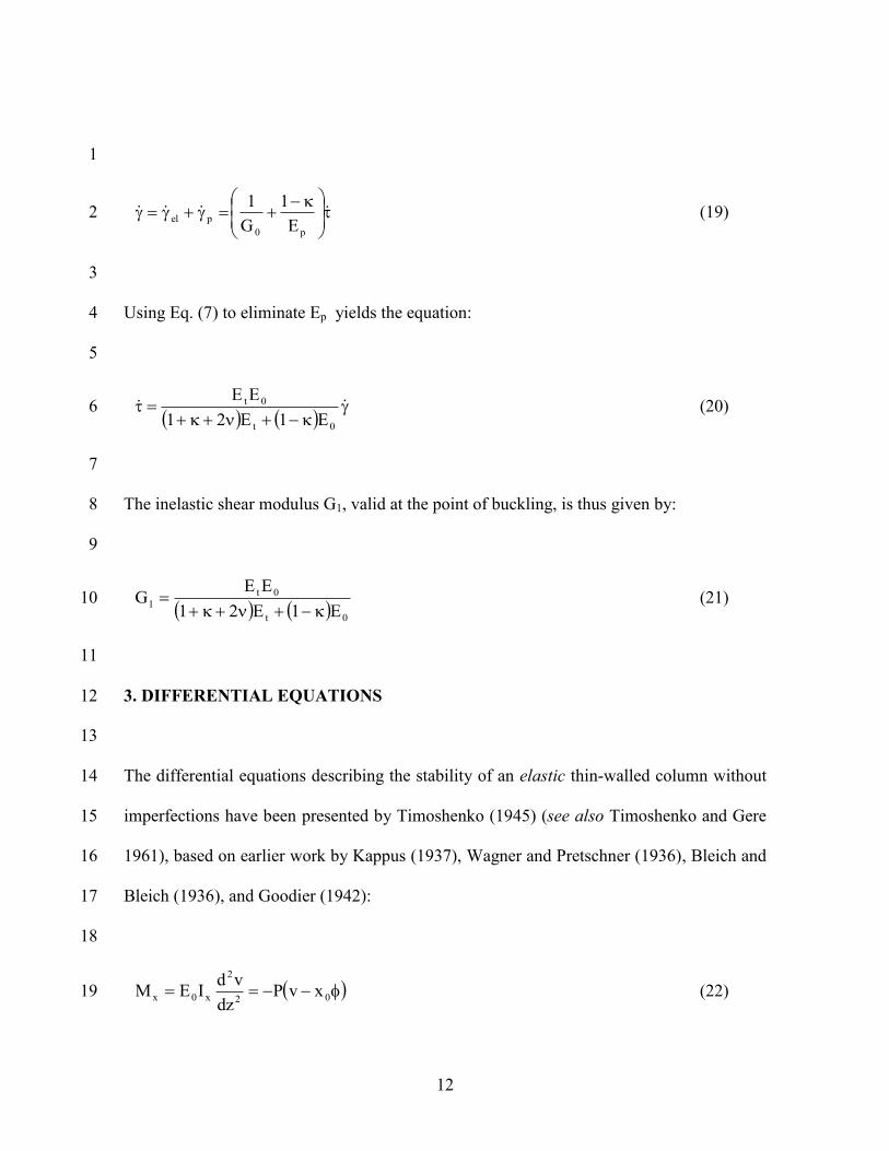
1
p0
pelE
1
G
1 (19) 2
3
Using Eq. (7) to eliminate Ep yields the equation: 4
5
0t
0t
E1E21
EE (20) 6
7
The inelastic shear modulus G1, valid at the point of buckling, is thus given by: 8
9
0t
0t
1E1E21
EEG
(21) 10
11
3. DIFFERENTIAL EQUATIONS 12
13
The differential equations describing the stability of an elastic thin-walled column without 14
imperfections have been presented by Timoshenko (1945) (see also Timoshenko and Gere 15
1961), based on earlier work by Kappus (1937), Wagner and Pretschner (1936), Bleich and 16
Bleich (1936), and Goodier (1942): 17
18
02
2
x0x xvPdz
vdIEM (22) 19

13
02
2
y0y yuPdz
udIEM (23) 1
0dz
udPy
dz
vdPx
dz
dP
A
IJG
dz
dCE
2
2
02
2
02
2p
04
4
0
(24) 2
3
In the above equations, the z-axis has been chosen to coincide with the longitudinal axis of 4
the column, while the x- and y-axes are the principal axes within the cross-section (Fig. 4). 5
The displacements u and v are those of the shear centre in the x- and y-directions, 6
respectively, while the angle measures the rotation of the cross-section about the 7
longitudinal axis through the shear centre. Furthermore, x0 and y0 are the coordinates of the 8
shear centre relative to the centroid C, P is the axial load, Ix and Iy are the second moments 9
of area about the x- and y-axes, respectively, C is the warping constant, J is the torsional 10
constant, A is the cross-sectional area, and Ip is the polar moment of area: 11
12
2
0
2
0yxP yxAIII (25) 13
14
When considering bifurcation of an inelastic column, the torsional resistance associated 15
with pure St. Venant torsion is governed by shear stresses which are linked to the shear 16
strains by the inelastic modulus G1, as determined by Eq. (21). Therefore, the torsional 17
rigidity G0J in Eq. (24) needs to be replaced by G1J for an inelastic column. A second 18
contribution to the torsional resistance results from the development of longitudinal 19
warping stresses in non-uniform torsion. In an inelastic material, the longitudinal stress and 20
14
strain increments at the onset of buckling are related through the tangent modulus Et. 1
Therefore, the warping resistance of an inelastic column at the onset of buckling is 2
governed by EtC. 3
Furthermore, at the buckling load the longitudinal stress and strain increments due to 4
bending are also linked by the tangent modulus Et. Shanley’s insights (1947) thereby 5
indicate that no elastic unloading on the convex side of bending must be considered. 6
Based on these considerations, the differential equations describing stability of an inelastic 7
column can now be written as: 8
9
0xvPdz
vdIE 02
2
xt (26) 10
0yuPdz
udIE 02
2
yt (27) 11
0dz
udPy
dz
vdPx
dz
dP
A
IJG
dz
dCE
2
2
02
2
02
2p
14
4
t
(28) 12
13
3. COLUMNS WITH A DOUBLY SYMMETRIC CROSS-SECTION 14
For columns with a doubly symmetric cross-section, the centroid and the shear centre 15
coincide, so that: x0 = y0 = 0, and: Ip = Ix + Iy. Eqs. (26-28) now become a set of uncoupled 16
differential equations: 17
18
0Pvdz
vdIE
2
2
xt (29) 19
15
0Pudz
udIE
2
2
yt (30) 1
0dz
dP
A
IJG
dz
dCE
2
2p
14
4
t
(31) 2
3
For a pin-ended column where the end sections are free to warp, but prevented from 4
rotating about the longitudinal column axis, the boundary conditions are: 5
6
0vu for Lz,0z 7
8
0dz
d
dz
vd
dz
ud2
2
2
2
2
2
for Lz,0z (32) 9
10
Adopting the boundary conditions (32), the solution of Eqs. (26-28) is (see Timoshenko 11
and Gere 1961): 12
13
2
xt2
xL
IEP (33) 14
15
2
yt2
yL
IEP (34) 16
17

16
2
2
t1
p LCEJG
I
AP (35) 1
2
3.1 Flexural Buckling 3
4
Eqs. (33) and (34), of course, do not represent new findings. Originally proposed by 5
Engesser (1889), the use of the tangent modulus to determine the pure flexural buckling 6
load of columns is widely used and accepted. Although elastic unloading at the convex side 7
of bending results in post-buckling capacity (Shanley 1947), this post-buckling capacity is 8
usually marginal for non-linear metals as a result of the rapid loss of stiffness at higher 9
strain levels. Consequently, the tangent modulus approach has been demonstrated to yield 10
good predictions of the ultimate capacity of columns failing in flexural buckling. Research 11
confirming this finding has been carried out by, among others, Osgood and Holt (1938), 12
Leary and Holt (1946), Holt and Leary (1946), Johnson and Winter (1966), Rasmussen and 13
Hancock (1993) and van den Berg (2000). The aforementioned research includes test on 14
various aluminium and stainless steel alloys and encompasses columns of various cross-15
sections. 16
Heimerl and Roy (1945) conducted tests on extruded 75S-T aluminium “thin-strip” 17
columns with rectangular cross-section. These particular tests are here used to illustrate Eq. 18
(34). Figure 5 compares the reported data to Eq. (34), where a Ramberg-Osgood 19
representation (Ramberg and Osgood 1943) of the stress-strain curve was used to calculate 20
the tangent modulus: 21
17
1
1n
%2.0
0%2.0
0%2.0
t
nE002.0
EE
(36) 2
3
In Eq. (36), 0.2% is the 0.2% proof stress of the material and n is the strain-hardening 4
parameter. For the material under consideration: E0 = 72.5 GPa, 0.2% = 534 MPa and n = 5
22, as determined from the provided stress-strain curves in Heimerl and Roy (1945). 6
Iterative calculations are necessary to solve Eq. (34). It is seen from Figure 5 that Eq. (34), 7
representing the flexural buckling load of a perfectly straight column, constitutes an upper 8
bound to the experimental data, which include the effects of initial imperfections. 9
10
3.2 Pure Torsional Buckling 11
12
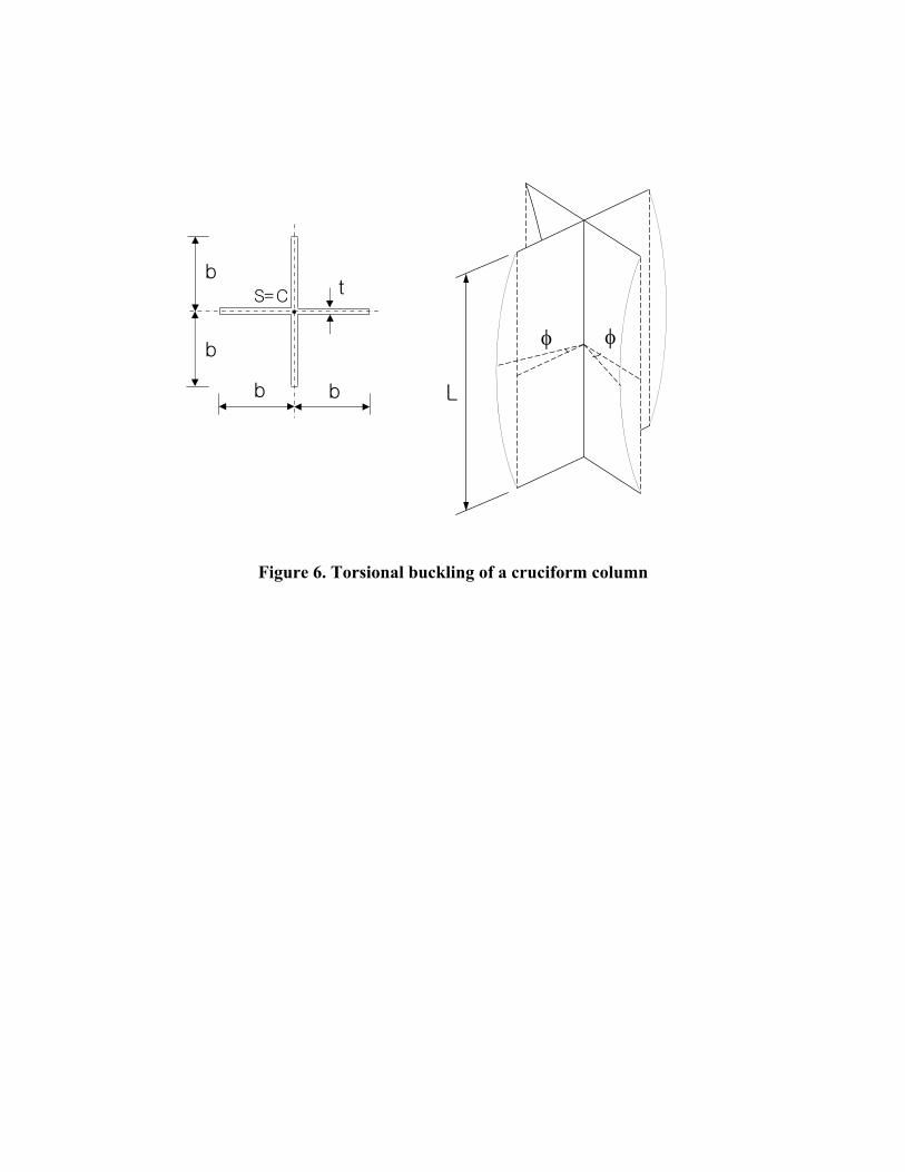
Doubly symmetric sections with low torsional rigidity may be subject to a pure torsional 13
buckling mode. The proposed theory is here verified against experimental data by 14
Hopperstad et al. (1999), who conducted torsional buckling tests on extruded AA6082-T4 15
aluminium cruciform columns. Tests were conducted for five b/t ratios (see Figure 6 for a 16
definition of b and t), while the L/b ratio (with L representing the column length) was kept 17
constant at 6. The out-of-flatness of the flanges was reported to be less than 0.005b. All 18
columns were tested between fixed end plates, so that warping of the end sections was 19
prevented. The boundary conditions for torsion can thus be expressed as: 20

18
1
0 and 0dz
d
for Lz,0z (37) 2
3
which results in the replacement of Eq. (35) by (Timoshenko and Gere 1961): 4
5
2
2
t1
p L
4CEJG
I
AP (38) 6
7
The inelastic shear modulus G1 was calculated using Eq. (21) with = 0.33, = -0.5 and 8
with the tangent modulus Et determined by Eq. (36). The material parameters of the 9
AA6082-T4 alloy, as reported by Hopperstad et al. (1999), are: E0 = 69.7 GPa, 0.2% = 131 10
MPa and n = 23. Since the heart lines of the constituent plate elements of the cross-section 11
intersect at the shear centre, the classical theory of torsion (see Timoshenko and Gere 1961) 12
dictates that C = 0, leaving only the contribution of pure torsion in Eq. (35): 13
14
2
13
3
1
p
1cr
b
tG
3/tb4
3/bt4G
I
JG
A
P
(39) 15
16
However, a more accurate approach originates from the realization that torsional buckling 17
of the cruciform column is synonymous with local buckling of the four constituent flanges 18
as plates simply supported along one longitudinal edge, with the other longitudinal edge 19

19
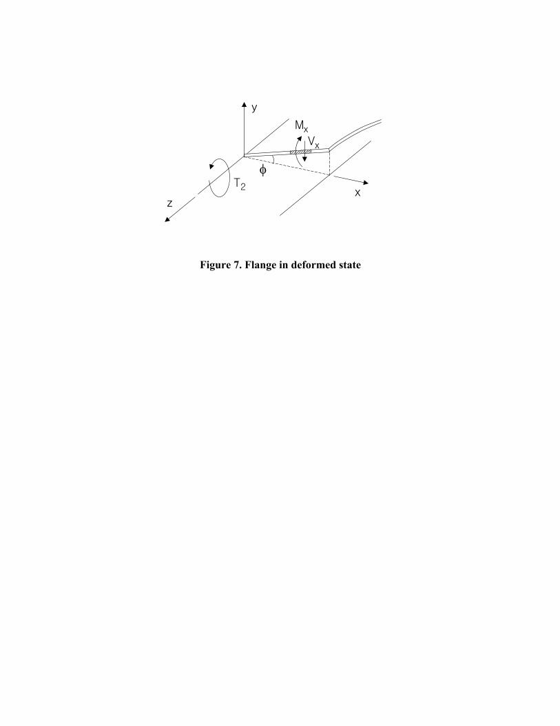
free (Figure 6), and that consequently longitudinal bending stresses develop in the flanges 1
during torsional buckling. These bending stresses implied by plate theory are indeed 2
equivalent to the warping stresses in the context of column theory. This allows for a more 3
accurate determination of C by noting that, if transverse plate bending is neglected (Figure 4
7): 5
6
x).z()z,x(v (40) 7
8
and that the moment per unit plate width Mx is given by: 9
10
xdz
d
12
tE
dz
vd
12
tEM
2
23
t2
23
tx
(41) 11
12
Consequently, the shear force per unit plate width Vx is given by: 13
14
xdz
d
12
tE
dz
dMV
3
33
tx
x
(42) 15
16
And the associated torsional moment is: 17
18
b
0
3
333
tx2dz
d
9
tbEdxxV4T (43) 19
20

20
which yields: 1
2
9
tbC
33
(44) 3
4
A slightly more accurate equation can be obtained by replacing Eq. (41) by the expression 5
for Mx obtained from inelastic plate theory (Becque 2010), while maintaining the 6
displacement field proposed by Eq. (40): 7
8
xdz
d
EE1
EE
12
t
x
v
z
v
EE1
EE
12
tM
2
2
t0
t0
3
2
2
2
2
t0
t0
3
x
9
(45) 10
The corresponding shear force is: 11
12
x
M
z
MV
yxxx
, (46) 13
14
where Myx = 0 as a result of Eq. (40). 15
Eq. (38) then becomes: 16
17
22
t0
t0
2
1crL
t
3EE1
EE
b
tG
A
P
(47) 18
19

21
Since the warping resistance of the cruciform section is a priori small, Eq. (47) leads to 1
predictions which differ by less than 0.5% from the results of Eq. (38), combined with Eq. 2
(44), for the examples here considered. 3
Figure 8 plots the experimental results reported by Hopperstad et al. (1999) and compares 4
them with the predictions of Eq. (38), using Eq. (44) to calculate C. Iterative calculations 5
are again necessary to solve Eq. (38). Good agreement between the predicted and the 6
experimentally measured buckling stresses is obtained: the average ratio of the predicted to 7
the measured buckling stress is 0.98. For comparison, Figure 8 also displays Ilyushin’s 8
(1947) solution for the buckling problem of a cruciform column, which is based on plastic 9
deformation theory: 10
11
2
t
s
22
t
crb
t
E
E
L
b
3
4
3
E
(48) 12
13
where Es is the secant modulus. 14
On a related note, it is seen from the experimental data that, since plates possess significant 15
post-buckling capacity, the ultimate stress of the cruciform columns can considerably 16
outreach the buckling stress. This is particularly true for the longer specimens, which 17
buckle elastically. 18
Figure 9 compares the experimental data of Hopperstad et al. (1999) to two alternate 19
solutions, the first of which was obtained from inelastic plate theory (Becque 2010), while 20
the second one resulted from applying Eq. (39). With respect to Eq. (39), it is noted that the 21

22
omitted term in Eq. (38) becomes smaller for smaller values of Et (meaning larger stresses 1
and thus smaller b/t values), but on the other hand increases for larger C/L2 values (which 2
also means smaller b/t values in Fig. 9, since the aspect ratio b/L is fixed). Which effect 3
will dominate depends on the material stress-strain curve. With respect to the solution 4
obtained from inelastic plate theory, each flange is regarded as a plate simply supported 5
along three edges with one longitudinal edge free. Neither theory accounts for the slight 6
rotational end restraint present in the experiments, which becomes relatively more 7
important for longer specimens. On the other hand, for very short columns, plate theory 8
yields better predictions over Eq. (38) because column theory fails to account for the 9
transverse plate bending, which becomes important in shorter specimens. 10
11
4. COLUMNS WITH A SINGLY SYMMETRIC CROSS-SECTION 12
13
If the x-axis is an axis of symmetry, then: y0 = 0, and Eqs. (26-28) become: 14
15
0Pudz
udIE
2
2
yt (49) 16
17
0xvPdz
vdIE 02
2
xt (50) 18
19
0dz
vdPx
dz
dP
A
IJG
dz
dCE
2
2
02
2p
14
4
t
(51) 20

23
1
The flexural buckling mode about the y-axis, described by Eq. (49), which is dependent on 2
u, is uncoupled from the flexural-torsional buckling mode in the y-direction, described by 3
Eqs. (50-51), which contain v and . If the column ends are free to rotate about the x- and 4
y-axes, but prevented from warping and rotating about the longitudinal axis, the flexural-5
torsional buckling load P is determined by the equation (see Timoshenko and Gere 1961): 6
7
0PPPPPPI
IIxx
2
p
yx
(52) 8
9
where Px and P are given by Eqs. (33) and (38) respectively. Consequently: 10
11
p
yx
x
2
xx
yx
p
I
IIPP4PPPP
II2
IP (53) 12
13
Eq. (53) is first verified against experimental data provided by Leary and Holt (1946). The 14
researchers tested equal-leg angles with dimensions 63.5mm x 63.5mm x 6.35mm, 15
manufactured by extrusion of 14S-T aluminium. The reported material properties are: E0 = 16
73.1 GPa, 0.2% = 394 MPa, n = 27 and = 0.33. The overall imperfections were reported to 17
be less than L/1000. Using Eq. (44), the warping constant C was calculated as: 18
19

24
18
tbC
33
(54) 1
2
Figure 10 compares the experimental data to the theoretical predictions. Iterative 3
calculations are necessary to solve Eq. (53). The theory confirms the experimental 4
observation that the longer columns fail by flexural buckling about the weak principal axis 5
of the angle, while the shorter columns fail by flexural-torsional buckling. A close match 6
between the theory and the experiment is obtained, with an average ratio of the predicted to 7
the measured load of 1.00 for the specimens failing by flexural-torsional buckling. It should 8
be noted that the test data represent ultimate (failure) stresses, while the theory predicts 9
buckling stresses. The close match suggests that post-buckling capacity is limited for this 10
type of inelastic buckling. 11
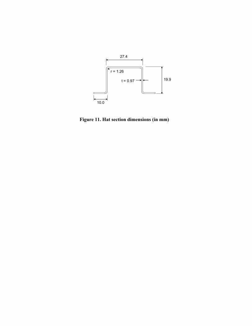
Secondly, Eq. (53) is verified against tests on 3Cr12 stainless steel hat section columns, 12
failing by flexural-torsional buckling (van den Berg 1988). The material properties, as 13
reported by van den Berg are: E0 = 222 GPa, 0.2% = 319 MPa and n = 6.3. The cross-14
sectional dimensions are shown in Fig. 11. Figure 12 compares the results of Eq. (53) with 15
the experimental data in dashed line. It is seen that the capacity of the shorter specimens 16
significantly exceeds the predictions. The difference can be attributed to the fact that the 17
sections were cold-formed, resulting in significantly increased corner properties (see, 18
among others, Lecce 2006, Becque 2009). Due to the location of the corners with respect to 19
the principal axes, the enhanced corner areas considerably increase the effective second 20
moment of area Iy, while also improving the warping resistance. This effect becomes more 21
25
pronounced for specimens failing at higher stresses in the inelastic range. To take into 1
account these enhanced corner properties, the cross-sectional properties Ix, Iy, A, J and C 2
were recalculated, where the corners were given an equivalent increased thickness teq: 3
4
tE
Et
t
tc
eq (55) 5
6
In the above Eq. (53), Et is the tangent modulus of the material constituting the flat 7
segments of the cross-section, while Etc is the tangent modulus of the rounded corner 8
material, calculated at the same strain value. The Ramberg-Osgood parameters necessary to 9
calculate Etc were obtained from Lecce (2006): 0.2% = 571 MPa and n = 4. Iterative 10
calculations are necessary to ensure Et is calculated at the buckling stress. Figure 12 11
displays the results of these calculations in solid line. The inelastic local buckling stress of 12
the cross-section, which was calculated using the method set out by Becque et al. (2011), is 13
also indicated. It is seen that good agreement is obtained between the predictions of Eq. 14
(53), taking into account the enhanced corners, and the experimental data, up to a stress 15
level slightly below the inelastic local buckling load. Above this level, local-overall 16
interaction buckling becomes the governing failure mode, which cannot be accounted for 17
using this column theory. The average ration of predicted to experimental load is 1.00 for 18
the specimens failing in pure flexural-torsional buckling. 19
20
CONCLUSIONS 21

26
1
The paper presents the differential equations governing flexural, torsional and flexural-2
torsional buckling of inelastic columns. The theory is consistent with the principles of 3
plastic flow theory and avoids the plastic buckling paradox by deriving an expression for 4
the inelastic shear stiffness while considering an infinitesimal solid element transitioning to 5
its shear-deformed state. 6
The theory is verified against experimental data available in literature, including examples 7
of the pure flexural and pure torsional buckling modes of columns with a doubly symmetric 8
cross-section, as well as examples of the flexural and flexural-torsional buckling modes of 9
columns with a singly symmetric cross-section. Good agreement between the theory and 10
the experiment is observed over the whole range of buckling modes. 11
12
13

27
REFERENCES 1
2
Batdorf, S.B. (1949). “Theories of Plastic Buckling.” Journal of the Aeronautical Sciences, July, 3
404-408. 4
5
Bazant, Z.P., and Cedolin, L. (1991). Stability of Structures, Oxford University Press, Oxford, U.K. 6
7
Becque, J. (2009). “Experimental Investigation of Local-Overall Interaction Buckling of Stainless 8
Steel Lipped Channel Columns.” Journal of Constructional Steel Research, 65, 1677-1684. 9
10
Becque, J. (2010). “Inelastic Plate Buckling” Journal of Engineering Mechanics, ASCE, 136(9), 11
1123-1130. 12
13
Becque, J., Lathourakis, P., and Jones, R. (2011). “Experimental verification of an inelastic plate 14
theory based on plastic flow theory.” Thin-Walled Structures, 49(12), 1563-1572. 15
16
Bleich, H., and Bleich, F. (1936). “Biegung, Drillung und Knickung von Stäben aus Dünnen 17
Wänden.” Vorbericht zum 2. Kongress der Internazionalen Vereinigung für Brücken- und 18
Hochbau. Verlag Ernst & Sohn, Berlin. 19
20
Considère, A. (1891). “Resistance des pièces comprimées.” Congrès international des procédés de 21
construction, Paris, Vol. 3, p. 371. 22
23

28
Drucker, D.C. (1950). “Some Implications of Work Hardening and Ideal Plasticity.” Quarterly of 1
Applied Mathematics 7, p. 411-418. 2
3
Engesser, F. (1889). Zeitschrift fur Architektur und Ingenieurwesen, 35, 455. 4
5
Engesser, F. (1895). Schweizerische Bauzeitung, 26, 24. 6
7
Gonçalves, R., and Camotim, D. (2007). “Thin-walled member plastic bifurcation analysis using 8
generalised beam theory.” Advances in Engineering Software, 38, pp. 637-646. 9
10
Goodier, J.N. (1942). “Flexural-Torsional Buckling of Bars of Open Section.” Cornell University 11
Engineering Experiment Station Bulletin, 28, 16p. 12
13
Heimerl, G.J., and Roy, J.A. (1945). “Column and Plate Compressive Strengths of Aircraft 14
Structural Materials – Extruded 75S-T Aluminum Alloy” NACA Wartime Report, originally 15
issued as Advance Restricted Report L5F08a. 16
17
Holt, M., and Leary, J.R. (1946). “The Column Strength of Aluminum Alloy 75S-T Extruded 18
Shapes.” NACA Technical Note No. 1004. 19
20
Hopperstad, O.S., Langseth, M., and Tryland, T. (1999). “Ultimate Strength of Aluminium Alloy 21
Outstands in Compression: Experiments and Simplified Analysis.” Thin-Walled Structures, 22
34, 279-294. 23
24

29
Hutchinson, J.W. (1974). “Plastic Buckling.” Advances in Applied Mechanics, C-S. Yih, ed., 1
Academic, New York, 67-144. 2
3
Hutchinson, J.W., and Budiansky, B. (1976). “Analytical and Numerical Study of the Effects of 4
Initial Imperfections on the Inelastic Buckling of a Cruciform Column.” Buckling of 5
Structures, Proceedings of the IUTAM Symposium, Cambridge, Massachussets, B. 6
Budiansky, editor, Springer, Berlin, 98-105. 7
8
Ilyushin, A.A. (1947). “The Elasto-Plastic Stability of Plates.” NACA Technical Note No. 1188. 9
10
Johnson, A., and Winter, G.. (1966). “Behaviour of Stainless Steel Columns and Beams.” Journal 11
of Structural Engineering, American Society of Civil Engineers, ASCE 92(ST5), 97-118. 12
13
Kappus, R. (1937) “Drillknicken zentrisch gedruckter Stabe mit offenem Profil im elastischen 14
Bereich.” Luftfahrtforschung, 14 (9), 444-457 (translated into NACA Technical 15
Memorandum No. 851 (1938)). 16
17
Leary, J.R., and Holt, M. (1946). “Column Strength of Aluminum Alloy 14S-T Extruded Shapes 18
and Rod.” NACA Technical Note No. 1027. 19
20
Lecce, M. (2006). Distortional Buckling of Stainless Steel Sections. PhD Thesis, School of Civil 21
Engineering, University of Sydney, Sydney. 22
23
Lubliner, J. (1990). Plasticity Theory, Macmillan, New York. 24

30
1
Onat, E.T., and Drucker, D.C. (1953). “Inelastic Instability and Incremental Theories of Plasticity.” 2
Journal of the Aeronautical Sciences, 20(3), 181-186. 3
4
Osgood, W.R., and Holt, M. (1938). “The Column Strength of Two Extruded Aluminum-Alloy H-5
Sections.” NACA Technical Report No. 656. 6
7
Ramberg, W., and Osgood, W.R. (1943). NACA Technical Note No. 902. 8
9
Rasmussen, K.J.R., and Hancock, G.J. (1993). “Design of Cold-Formed Stainless Steel Tubular 10
Members. I: Columns.” Journal of Structural Engineering, 119(8), 2349-2367. 11
12
Rønning, L., Hopperstad, O.S., and Larsen, P.K. (2010). “Numerical study of the effects of 13
constitutive models on plastic buckling of plate elements.” European Journal of 14
Mechanics A/Solids, 29, pp. 508-522. 15
16
Ruocco, E. (2015). “Elastoplastic buckling analysis of thin-walled structures.” Aerospace 17
Science and Technology, 43, pp. 176-190. 18
19
Shamass, R., Alfano, G., and Guarracino, F. (2015). “An investigation into the plastic buckling 20
paradox for circular cylindrical shells under non-proportional loading.” Thin-Walled 21
Structures, 95, pp. 347-362. 22
23

31
Shanley, F. (1947). “Inelastic Column Theory.” Journal of the Aeronautical Sciences, 14(5), 261-1
276. 2
3
Timoshenko, S.P. (1945). “Theory of Bending, Torsion and Buckling of Thin-Walled Members of 4
Open Cross-Section.” Journal of the Franklin Institute, 239(5), 343-361. 5
6
Timoshenko, S.P., and Gere, J.M. (1961). Theory of Elastic Stability, 2nd
edition, McGraw-Hill, 7
New York. 8
9
van den Berg, G.J. (1988). “The Torsional-Flexural Buckling Strength of Cold-Formed Stainless 10
Steel Columns.” Proceedings of the Ninth International Specialty Conference on Cold-11
Formed Steel Structures, Missouri-Rolla, eds. Yu, W.W., and Senne, J.H. 12
13
van den Berg, G.J. (2000). “The Effect of the Non-Linear Stress-Strain Behaviour of Stainless Steel 14
on Member Capacity.” Journal of Constructional Steel Research, 54(1), 135-160. 15
16
Wagner, H., and Pretschner, W. (1936). Luftfahrtforschung, 11, 174-180 (translated into NACA 17
Technical Memorandum No. 784). 18
19
Wang, C.M., and Tun Myint Aung (2007). “Plastic buckling analysis of thick plates using p-Ritz 20
method” International Journal of Solids and Structures, 44, 6239-6255. 21
22
Wang, C.M., Xiang, Y., and Chakrabarty, J. (2001). “Elastic/plastic buckling of thick plates.” 23
International Journal of Solids and Structures, 38, 8617-8640. 24

32
1
Wang, X., and Huang, J. (2009). “Elastoplastic buckling analyses of rectangular plates under biaxial 2
loadings by the differential quadrature method.” Thin-Walled Structures, 47, 14-20. 3
4
ε ε ε
σ σσ
σcr
Et
E0
Ep
pel
ε ε εel p
Figure 1. Material stress-strain curve
-1.5
-1
-0.5
0
0.5
1
1.5
-2 -1.5 -1 -0.5 0 0.5 1 1.5 2
σ1/fy
σ2/fy
εp
.
Figure 2. von Mises surface

Figure 3. a. Infinitesimal element within the column, b. Mohr͛s circle of incremental plastic strain,
c. Mohr͛s circle of incremental stress

C
O
C’C’’
x
y
O’
v
u
y0
x0
φ
t
ds
s
Figure 4. Column cross-section

0
100
200
300
400
500
600
700
0 25 50 75 100
Le/r
Str
ess (
MP
a)
Experiment
Tangent Modulus Eqn.
Euler Curve
Figure 5. Tangent modulus curve vs. flexural buckling stress
b b
b
btS=C
φ φ
L
Figure 6. Torsional buckling of a cruciform column
y
xz
φ
MxVx
T2
Figure 7. Flange in deformed state

0
25
50
75
100
125
150
0 10 20 30 40
b/t
Str
ess (
MP
a)
Buckling stress (exp.)
Ultimate strength (exp.)
Proposed theory
Deformation theory
Elastic buckling
T4
Figure 8. Torsional buckling of a cruciform section (AA6082-T4)

0
25
50
75
100
125
150
0 10 20 30 40
b/t
Str
ess (
MP
a)
Buckling stress (exp.)
G (t/b)
Inelastic Plate Theory
T4
1
2
Figure 9. Approximate solutions for the cruciform column buckling problem

0
100
200
300
400
500
0 1000 2000 3000
L (mm)
Str
ess (
MP
a)
Flex. (Elastic)
Flex. (Inelastic)
Flex.-Tors.
(Inelastic)
Flex.-Tors.
(Elastic)
Figure 10. Flexural-torsional buckling of aluminium angles
t = 0.97
r = 1.26
10.0
27.4
19.9
Figure 11. Hat section dimensions (in mm)

0
10
20
30
40
0 250 500 750 1000
L (mm)
Lo
ad (
kN
)
Experiment
Without enhanced corners
With enhanced corners
Local buckling load
Elastic column buckling
3Cr12
Figure 12. Flexural-torsional buckling of a hat section column