Embed Size (px)
Citation preview
1 2 3 4 5 6 7 8 91011121314151617181920212223242526272829303132333435363738394041424344454647484950515253545556576061
The Application of IEC61850 Standard in the
Online Monitoring System of the Smart Substation
Geng Baohong 1, Wang Zhiming
2, Ge Weichun
2, Wang Chenggang
2, Li Shuyang
2, Gao Qiang
1,3
1 Northeast Electric Power Research Institute, Shenyang, China
2Liaoning Electric Power Company Limited, China
3 Shanghai Jiao Tong University, China
Abstract : This paper discussed the application of online
monitoring system based on IEC61850 standard in the smart
substation. Firstly, the functions and performance
requirements of online monitoring system have been discussed,
and the functional model and interface model of online
monitoring based on IEC61850 have been established;
Secondly, the application schema of online monitoring system
has been designed for smart substation. Furthermore,
according to the practical application in the pilot project, the
validity of the models and the schema has been verified, and a
summary of the application has been given.
Keywords: IEC61850, Online Monitoring System, Smart
Substation, Logical Node, ACSI
I. INTRODUCTION
The IEC61850 standard is the main standard for smart
substation. It has been successfully used in the
communication of automation system in smart substation.
The online monitoring system is an important component
of the secondary system of the smart substations. It is the
primary data source of the status visualization of primary
equipments. Therefore, the online monitoring system must
comply with the IEC61850 standard. However, the
application of online monitoring was not widespread in the
past, and was not fully integrated into the automation system, either. Therefore, many models used for online
monitoring system are not given in the IEC61850 standard
[4]. The application of the online monitoring system based
on IEC61850 standard is immature. In order to achieve
standardization of the online monitoring system in smart
substation, firstly, the function and performance
characteristics of the online monitoring system should be
analyzed based on the modeling principles of IEC61850
standard [1][3]. Secondly, the necessary expansion and
selection of the existing functional and service models in
IEC61850 standard should be done. Finally, the actual
online monitoring system schema based on these models should be designed to meet the requirements of the
application in smart substation. The schema should be used
in practical engineering of smart substation project. The
validity of these models will be verified as the online
monitoring system is successfully applied in real project.
Then, the experience of this project using these models will
provide the guidance for the follow-up projects.
II. IEC61850 MODELS
The goal of the IEC61850 standard is the interoperability
between IEDs (intelligent electronic devices) from different
manufacturers in the substation automation system. Various
functions and performance requirements of the substation
automation system have been analyzed, and functional
models, as well as services for the interaction between the
functional models have been defined in the standard. In
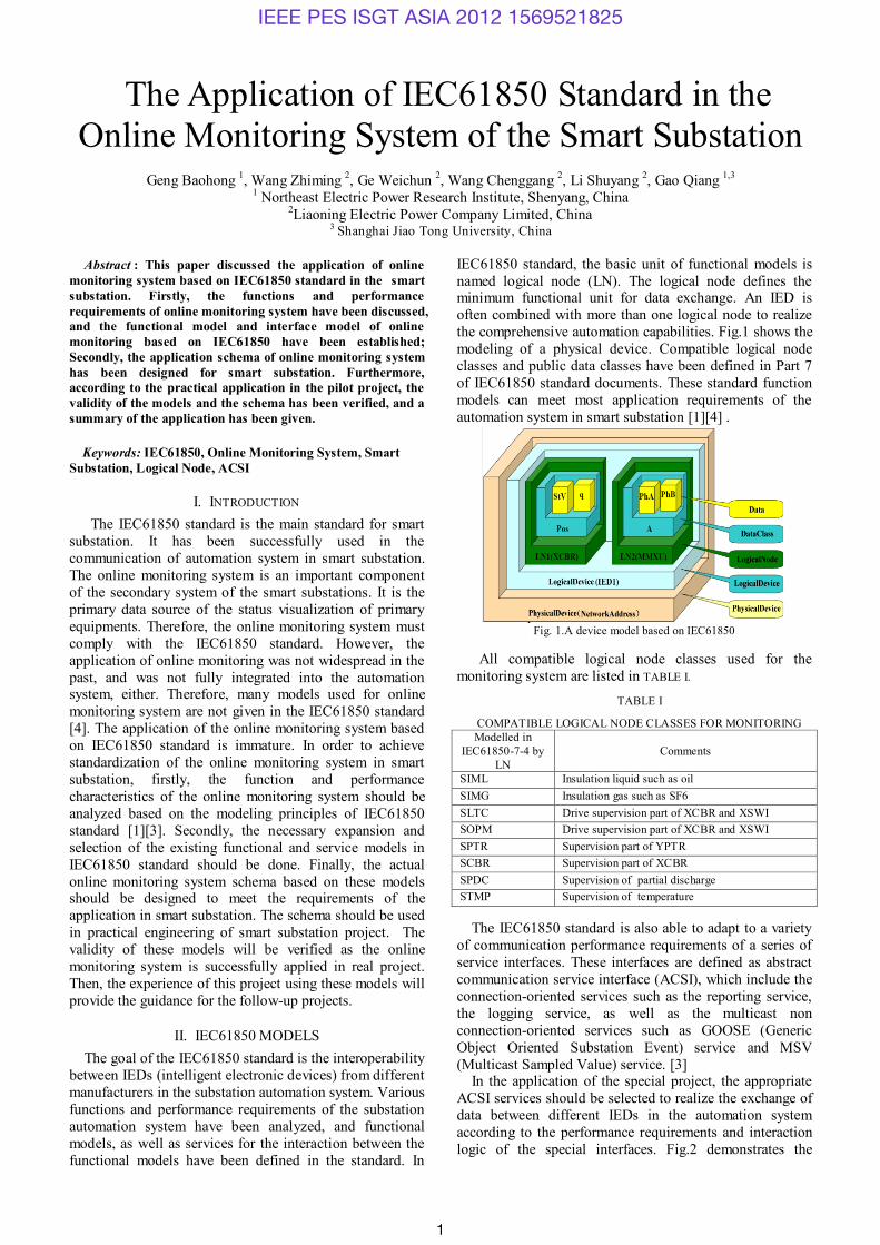
IEC61850 standard, the basic unit of functional models is
named logical node (LN). The logical node defines the minimum functional unit for data exchange. An IED is
often combined with more than one logical node to realize
the comprehensive automation capabilities. Fig.1 shows the
modeling of a physical device. Compatible logical node
classes and public data classes have been defined in Part 7
of IEC61850 standard documents. These standard function
models can meet most application requirements of the
automation system in smart substation [1][4] .
Fig. 1.A device model based on IEC61850
All compatible logical node classes used for the
monitoring system are listed in TABLE I.
TABLE I
COMPATIBLE LOGICAL NODE CLASSES FOR MONITORING
Modelled in
IEC61850-7-4 by
LN
Comments
SIML Insulation liquid such as oil
SIMG Insulation gas such as SF6
SLTC Drive supervision part of XCBR and XSWI
SOPM Drive supervision part of XCBR and XSWI
SPTR Supervision part of YPTR
SCBR Supervision part of XCBR
SPDC Supervision of partial discharge
STMP Supervision of temperature
The IEC61850 standard is also able to adapt to a variety
of communication performance requirements of a series of
service interfaces. These interfaces are defined as abstract
communication service interface (ACSI), which include the
connection-oriented services such as the reporting service,
the logging service, as well as the multicast non
connection-oriented services such as GOOSE (Generic
Object Oriented Substation Event) service and MSV
(Multicast Sampled Value) service. [3] In the application of the special project, the appropriate
ACSI services should be selected to realize the exchange of
data between different IEDs in the automation system
according to the performance requirements and interaction
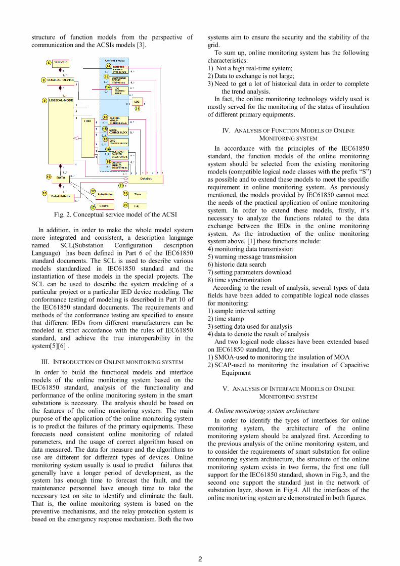
logic of the special interfaces. Fig.2 demonstrates the
IEEE PES ISGT ASIA 2012 1569521825
1
1 2 3 4 5 6 7 8 91011121314151617181920212223242526272829303132333435363738394041424344454647484950515253545556576061
structure of function models from the perspective of
communication and the ACSIs models [3].
Fig. 2. Conceptual service model of the ACSI
In addition, in order to make the whole model system more integrated and consistent, a description language
named SCL(Substation Configuration description
Language) has been defined in Part 6 of the IEC61850
standard documents. The SCL is used to describe various
models standardized in IEC61850 standard and the
instantiation of these models in the special projects. The
SCL can be used to describe the system modeling of a
particular project or a particular IED device modeling. The
conformance testing of modeling is described in Part 10 of
the IEC61850 standard documents. The requirements and
methods of the conformance testing are specified to ensure
that different IEDs from different manufacturers can be modeled in strict accordance with the rules of IEC61850
standard, and achieve the true interoperability in the
system[5][6] .
III. INTRODUCTION OF ONLINE MONITORING SYSTEM
In order to build the functional models and interface
models of the online monitoring system based on the IEC61850 standard, analysis of the functionality and
performance of the online monitoring system in the smart
substations is necessary. The analysis should be based on
the features of the online monitoring system. The main
purpose of the application of the online monitoring system
is to predict the failures of the primary equipments. These
forecasts need consistent online monitoring of related
parameters, and the usage of correct algorithm based on
data measured. The data for measure and the algorithms to
use are different for different types of devices. Online
monitoring system usually is used to predict failures that
generally have a longer period of development, as the system has enough time to forecast the fault, and the
maintenance personnel have enough time to take the
necessary test on site to identify and eliminate the fault.
That is, the online monitoring system is based on the
preventive mechanisms, and the relay protection system is
based on the emergency response mechanism. Both the two
systems aim to ensure the security and the stability of the
grid.
To sum up, online monitoring system has the following
characteristics:
1) Not a high real-time system;
2) Data to exchange is not large;
3) Need to get a lot of historical data in order to complete
the trend analysis. In fact, the online monitoring technology widely used is
mostly served for the monitoring of the status of insulation
of different primary equipments.
IV. ANALYSIS OF FUNCTION MODELS OF ONLINE
MONITORING SYSTEM
In accordance with the principles of the IEC61850
standard, the function models of the online monitoring
system should be selected from the existing monitoring
models (compatible logical node classes with the prefix “S”)
as possible and to extend these models to meet the specific
requirement in online monitoring system. As previously
mentioned, the models provided by IEC61850 cannot meet
the needs of the practical application of online monitoring
system. In order to extend these models, firstly, it’s
necessary to analyze the functions related to the data
exchange between the IEDs in the online monitoring
system. As the introduction of the online monitoring system above, [1] these functions include:
4) monitoring data transmission
5) warning message transmission
6) historic data search
7) setting parameters download
8) time synchronization
According to the result of analysis, several types of data
fields have been added to compatible logical node classes
for monitoring:
1) sample interval setting
2) time stamp
3) setting data used for analysis 4) data to denote the result of analysis
And two logical node classes have been extended based
on IEC61850 standard, they are:
1) SMOA-used to monitoring the insulation of MOA
2) SCAP-used to monitoring the insulation of Capacitive
Equipment
V. ANALYSIS OF INTERFACE MODELS OF ONLINE
MONITORING SYSTEM
A. Online monitoring system architecture
In order to identify the types of interfaces for online
monitoring system, the architecture of the online
monitoring system should be analyzed first. According to
the previous analysis of the online monitoring system, and
to consider the requirements of smart substation for online
monitoring system architecture, the structure of the online
monitoring system exists in two forms, the first one full
support for the IEC61850 standard, shown in Fig.3, and the
second one support the standard just in the network of substation layer, shown in Fig.4. All the interfaces of the
online monitoring system are demonstrated in both figures.
2

1 2 3 4 5 6 7 8 91011121314151617181920212223242526272829303132333435363738394041424344454647484950515253545556576061
Fig. 3.Achitecture1 of online monitoring system
Fig.4. Achitecture2 of online monitoring system
In the figures:
1) CAG-state access gateway machine;
2) CAC-state access controller;
3) CMU-monitoring unit; 4) CMA-monitoring devices;
5) Sensor - sensors;
6) SAS-smart substation automation system.
CAG is the master system located in the province grid,
which is responsible for receiving online monitoring data
throughout the region. It stores and displays the data,
management, and configuration of online monitoring
device at all levels. The CAC is a station level device in the smart substation. It is mainly used for getting all online
monitoring data within the smart substation, storing and
presenting data, analyzing the fault based on these data,
sending information to the CAG and downloading control
commands and settings from CAG. The CMU is a device in
bay level, which is used for converting the data from non-
IEC61850 standard models to IEC61850 standard models,
and communicating with the CAC based on IEC61850
standard. The CMA and Sensors are devices in process
level. They are using for the status parameter data
measurements, and communicating with the upper device.
If the CMA/sensors support IEC61850 standard, the CMU can be canceled, and the online monitoring system will be
simplified as a two-level system as shown in Fig.4. But
most monitoring devices in the online monitoring system
cannot support the IEC61850 standard directly currently.
Therefore, the system structure shown in Fig.3 is widely
used.
B. interface modeling of online monitoring system
Although the online monitoring system has two structures, the interfaces based on IEC61850 standard are
exactly the same. Here we just discuss the modeling of the
interfaces based on the IEC61850 standard. In the chapter
III, functional analysis of the online monitoring system has
been done, and various logical interfaces can be identified
abstractly from these functions related to interactions.
These interfaces (including non IEC61850 interfaces) and
their comments are listed in TABLE II.
TABLE II
INTERFACES IN THE ONLINE MONITORING SYSTEM Interface Comments
IF1 datas transmission from CMU to CAC
IF2 warning messengers transmission from CMU to CAC
IF3 historical datas transmission from CMU to CAC
IF4 setting parameters download from CAC to CMU
IF5 time synchronization between CAC and CMU
IF6 Interface between CMU and CMA/Senser
IF7 Interface between CAC and SAS
IF8 Interface between CAC and CAG
In TABLE II, IF1 to IF5 and IF7 are the interfaces basis
of IEC61850 standard. Before modeling these interfaces,
the performance requirements and the interactive logic of each interface should be analyzed. Then, the suitable ACSI
for each interface will be selected to realize the modeling.
As previously described, online monitoring system does
not belong to the real-time systems. So most of its
interfaces don’t need high transfer speed. Most of data
transferred in the online monitoring system is small in
amount, and the bandwidth is less. But the partial discharge
spectra data and the waveform data of the closing coil have
large bytes to transfer. Therefore, these two types of data
transmission need to consider the ACSI model with a large
number of data transmissions. If the online monitoring
system shares network bandwidth with other systems, the possibility of its cause network congestion should be
evaluated. Here we can give an example to evaluate the
influence of the raw data transmission of partial discharge
monitoring on the network. The bytes of the data
transferred in a period of time can be calculated by the
equation as follow:
L=2*S*F*T
In this equation :
L- total bytes of raw data to transfer
S- number of sample points in one cycle(power
frequency)
F-power frequency T-total time of sampling
Assuming that S=1000 and T=1hour, then the L will be
720M bytes. It will take at least 1minute to transfer all
these data by network with 100M bandwidth. Therefore,
it’s important to select appropriate transfer method to
enhance the transmission performance.
In general, ACSI services based on the MMS protocol is
enough for the data transmission requirements of the online
monitoring system. According to the characteristics of
various services provided by IEC61850 standard and the
result of analysis above on the interfaces of the online
monitoring system, ACSI for each interface has been selected shown in TABLE III [3].
3
1 2 3 4 5 6 7 8 91011121314151617181920212223242526272829303132333435363738394041424344454647484950515253545556576061
TABLE III
SELECTED ACSI FOR INTERFACES
Interface ACSI IF1 URCB
IF2 LCB/File
IF3 RCB
IF4 SGCB
IF5 SNTP
IF7 RCB
In TABLE III: 1) RCB-Buffered Report Control Block;
2) URCB-Unbuffered Report Control Block;
3) LCB- Log Control Block;
4) File-File transmission;
5) SGCB-Setting Group Control Block;
6) SNTP-Simple Network Time Protocol;
VI. SCHEMA OF THE ONLINE MONITORING SYSTEM IN
SMART SUBSTATION
As the function models and interface models of the
online monitoring system have been built based on
IEC61850 standard, and the structure of the system has
been discussed clearly, the schema for a typical system can
be designed here as the guidance for the implement of
specific projects.
Considering that most monitoring devices cannot support
IEC61850 standard currently, the structure of the online
monitoring system should be a structure with 3 levels, which is shown in Fig.2. That is, CMU should be involved
in the system. Then, a typical structure of the online
monitoring system based on IEC61850 standard should be
like that shown in Fig.5.
Fig.5 a typical structure of the online monitoring system based on
IEC61850 standard
The IEDs(CAC and switchs) in the station level are
located in the relay protection room, and other IEDs are
located in the switching field. Communication between
IEDs in station level and IEDs in bay level are basis of
IEC61850 standard. Communication between IEDs in bay
level and IEDs in process level may apply to MODBUS
protocol basis of RS485 or UDP protocol basis of TCP/IP
or any other protocols. In this structure, the CAC and the
CMU are new devices involved to be compatible with the
framework of smart substation. Therefore, functions of
these two devices should be discussed here.
A. design of CAC
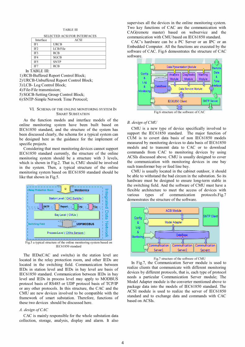
CAC is mainly responsible for the whole substation data
collection, storage, analysis, display and alarm. It also
supervises all the devices in the online monitoring system.
Two key functions of CAC are the communication with
CAG(remote master) based on webservice and the
communication with CMU based on IEC61850 standard.
CAC’s hardware can be a PC Server or an IPC or an
Embedded Computer. All the functions are executed by the
software of CAC. Fig.6 demosntrates the structure of CAC
software.
Fig.6 structure of the software of CAC
B. design of CMU
CMU is a new type of device specifically involved to
support the IEC61850 standard. The major function of
CUM is to covert data basis of non IEC61850 models
measured by monitoring devices to data basis of IEC61850
models and to transmit data to CAC or to download
commands from CAC to monitoring devices by using
ACSIs discussed above. CMU is usually designed to cover
the communication with monitoring devices in one bay
such transformer bay or feed line bay.
CMU is usually located in the cabinet outdoor, it should
be able to withstand the bad circum in the substation. So its hardware must be designed to ensure long-term stable in
the switching field. And the software of CMU must have a
flexible architecture to meet the access of devices with
various types of communication protocols.Fig.7
demonstrates the structure of the software.
Fig.7 structure of the software of CMU
In Fig.7, the Communication Server module is used to
realize clients that communicate with different monitoring
devices by different protocols, that is, each type of protocol
needs a particular Communication Server module; The
Model Adapter module is the converter mentioned above to
package data into the models of IEC61850 standard. The
ACSI module is used to realize the server of IEC61850
standard and to exchange data and commands with CAC
based on ACSIs.
4
1 2 3 4 5 6 7 8 91011121314151617181920212223242526272829303132333435363738394041424344454647484950515253545556576061
VII. APPLICATION OF THE ONLINE MONITORING IN THE
500KV SMART SUBSTATION
The schema of online monitoring system designed above
has been put into operation in a 500kV smart substation.
The validity of the models has been verified.
The 500kV smart substation is a pilot substation of the
state grid. The primary equipments, which are monitored
by the online monitoring system, are including transformers,
reactor, HGISs, GISs, and MOAs according to the design of the substation. Details of monitoring items and
parameters are listed in TABLE IV:
TABLE IV
INTERFACES IN THE ONLINE MONITORING SYSTEM Monitoring
type Monitoring parameters The number of
measuring points DGA H2, CH4, C2H6, C2H4,
C2H2, CO, CO2, H2O
2
PD Amplitude, count, phase and
type of partial discharge
2
Core
Grounding
Current
Grounding current 2
Oil
Temperature
Temperature 4
Winding
temprature
Temperature 4
Moisture and
density of
SF6
Humidity, temperature,
pressure and density
224
Insulation of
MOA
Leakage current, resistive
current, surge times
63
The physical structure of the system are shown in Fig.8
Fig.8 physical structure of the online monitoring system in the
500kVsmart substation
Here in Fig.8 the “Monitoring Groupe” consists of CMU
and monitoring devices in a bay, and the “Integrated Data
Network Switch” is used to communicating with the CAG. Two optical switches are used to set up the fiber Ethernet to
support the MMS protocol and the amount of CMU is 34.
A application software has been developed for CAC
apply to the structure in Fig.6 and Fig.9-11 shows the pages
of the software.
Fig.9 the interface showing the diagnosis result of dissolved gas in oil
using the method Duval’s triangle
Fig.10 interface showing the status of the primary equipment being
monitored
Fig.11 interface showing the diagnosis result of insulation parameters
by comparison method
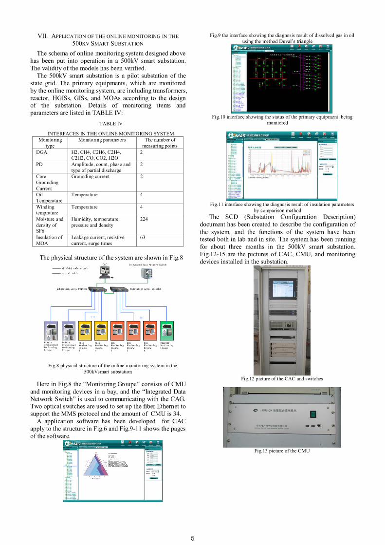
The SCD (Substation Configuration Description)
document has been created to describe the configuration of
the system, and the functions of the system have been tested both in lab and in site. The system has been running
for about three months in the 500kV smart substation.
Fig.12-15 are the pictures of CAC, CMU, and monitoring
devices installed in the substation.
Fig.12 picture of the CAC and switches
Fig.13 picture of the CMU
5

1 2 3 4 5 6 7 8 91011121314151617181920212223242526272829303132333435363738394041424344454647484950515253545556576061
Fig.14 pictures of the monitoring devices
VIII. CONCLUSION
In this paper, the function models and interface models
of the online monitoring system have been built based on
IEC61850 standard. Then, a typical schema of the online
monitoring system has been designed. Finally, an actual
system using these models and the schema has been
constructed, which is running in a pilot 500kV Smart
substation of State Grid. It will be the first online
monitoring system in china that is full compliance with
IEC61850 standard, and will guides the application of
IEC61850 standard in the follow-up projects. In the future,
the online monitoring system will be integrated into the substation automation system, the system structure will be
different from which debated in this paper, so there are still
many issues need to study on the application of online
monitoring system in the Smart substation.
REFERENCE
[1] IEC TEC57 “Communication networks and systems in substations –
Part 5:Communication requirements for functions and device
models” IEC Standard IEC61850-5:2003(E).
[2] IEC TEC57 “Communication networks and systems in substations –
Part 7-1:Basic communication structure for substation and feeder
equipment –Principles and models” IEC Standard IEC61850-7-
1:2003(E) .
[3] IEC TEC57 “Communication networks and systems in substations –
Part 7-2:Basic communication structure for substation and feeder
equipment –Abstract communication service interface (ACSI)” IEC
Standard IEC61850-7-2:2003(E) .
[4] IEC TEC57 “Communication networks and systems in substations –
Part 7-4:Basic communication structure for substation and feeder
equipment – Compatible logical node classes and data classes” IEC
Standard IEC 61850-7-4: 2010(E).
[5] IEC TEC57 “Communication networks and systems in substations –
Part 6: Configuration description language for communication in
electrical substations related to IEDs” IEC Standard IEC61850-
6:2007(E).
[6] IEC TEC57 “Communication networks and systems in substations –
Part 10: Conformance testing” IEC Standard IEC61850-10:2005(E).
6