Embed Size (px)
Citation preview
Graduate Student Works Worldwide Campus
5-2013
The Application of Advanced Composites for the Construction of The Application of Advanced Composites for the Construction of
Commercial Transport Aircraft Commercial Transport Aircraft
Mark D. Severson Embry-Riddle Aeronautical University, [email protected]
Follow this and additional works at: https://commons.erau.edu/ww-graduate-works
Part of the Aeronautical Vehicles Commons, Structural Materials Commons, and the Structures and
Materials Commons
Scholarly Commons Citation Scholarly Commons Citation Severson, M. D. (2013). The Application of Advanced Composites for the Construction of Commercial Transport Aircraft. , (). Retrieved from https://commons.erau.edu/ww-graduate-works/4
This Capstone is brought to you for free and open access by the Worldwide Campus at Scholarly Commons. It has been accepted for inclusion in Graduate Student Works by an authorized administrator of Scholarly Commons. For more information, please contact [email protected].
Running head: APPLICATION OF ADVANCED COMPOSITES 1
The Application of Advanced Composites for the
Construction of Commercial Transport Aircraft
Mark D. Severson
Embry-Riddle Aeronautical University
ASCI 691 Graduate Capstone Project
Submitted to the Worldwide Campus
in Partial Fulfillment of the Requirements for the Degree of
Master of Aeronautical Science
May 2013
APPLICATION OF ADVANCED COMPOSITES 2
Acknowledgements
I want to acknowledge and thank the speakers and participants at the 2013 CMH-
17/JAMS PMC Coordination Meeting at the Boeing Future of Flight Facility in Everett,
Washington for assisting me with my research and providing the necessary data for my analysis,
with special recognition given to Dr. Melanie Violette of the FAA in Renton, Washington for her
research guidance and interest in my project. Second, I want to thank ERAU Worldwide
Assistant Professor of Arts and Sciences, Dr. Heather Garten, for her statistical guidance, and all
of my ERAU Worldwide Instructors for their technical acumen that guided me through a very
challenging program of study. Finally, I want to thank my fiancée Michelle and her daughter
Kirstin for their patience and understanding during my entire MAS program and Capstone
project - without it, this research paper and my program completion would not have been
possible.
APPLICATION OF ADVANCED COMPOSITES 3
Abstract
This individual Capstone project examined and evaluated current industry methods of testing,
certification, and maintenance of advanced composite materials for the construction of
commercial transport aircraft and the FAA regulations governing their use. The project critically
compared and contrasted existing FAA standards and regulations governing the testing,
certification, and maintenance of advanced composites for commercial transport aircraft
structural applications with current industry practices to determine whether there were any areas
of conflict between the two in order to accept or reject that current testing, certification, and
maintenance procedures for advanced composites used in primary and secondary commercial
transport aircraft structures are standardized throughout the aerospace industry and sufficiently
capable of detecting damage or component failure. This was accomplished by performing a
qualitative and quantitative analysis utilizing meta-analysis to contrast and compare past and
current aerospace composite materials studies with non-destructive inspection (NDI) testing and
structural health monitoring (SHM) data to determine statistical significance that supported or
refuted the hypothesis of comprehensive process improvement throughout the industry. The
results of the analysis showed that the hypothesis was accepted for testing and certification, but
overwhelmingly rejected for current maintenance and repair. In addition, industry concerns were
examined to determine whether limitations exist that would preclude the future use of advanced
composites in structural applications based on current FAA standards and regulations. This
project determined how current industry practices and FAA methodologies for the testing,
certification, and maintenance of advanced composites in commercial transport aircraft structural
applications may need to be modified in order to capture and address future industry use.
Keywords: advanced composites, testing, certification, maintenance, damage detection
APPLICATION OF ADVANCED COMPOSITES 4
Proposal
(Approved by ERAU Worldwide Aeronautics Department on April 6th
, 2013)
The Application of Advanced Composites for the
Construction of Commercial Transport Aircraft
Structural Composite Materials Integration
The use of composite materials by the aerospace industry has increased over the past
several decades for the construction of commercial transport aircraft that now includes the use of
advanced composites in primary and secondary structures such as wings and fuselage
components. This increased use also brings with it the requirement for new validation tests,
certification processes, and standardized repair procedures that will differ significantly from
traditional metallic aircraft structure testing, certification, and repair. This recent expanded use
of advanced composites by aerospace manufacturers warrants further discussion into current and
future testing, certification, and repair procedures for primary and secondary structures advanced
composite parts and assemblies used in the construction of commercial transport aircraft.
The integration of composite materials for use in aerospace applications originated from
the desire to replace conventional metallic structures with a light-weight, higher strength
alternative. Advanced composites are used by the aerospace industry and in other high-
performance applications where high-strength and stiffness are required. Advanced composites
are composite materials that start with high-strength and high extensional stiffness fibers such as
carbon, boron, and aramid (Kevlar™) that are imbedded within a homogenous resin matrix of
epoxy, bismaleimide, or polyimide which then becomes a composite of the two separate
materials that forms a single material (laminate) with high strength and stiffness properties. The
strength and stiffness characteristics that are created by lightweight composite materials have
APPLICATION OF ADVANCED COMPOSITES 5
allowed them to replace traditional heavier metallic structures in order to yield a higher strength-
to-weight ratio for aerospace applications. Early structural use of advanced composites by
aerospace manufacturers included parts and assemblies such as doors and panels, engine
nacelles, control surfaces, and nose radomes. Due to the high-strength and stiffness properties of
advanced composites, the use has been expanded to include aircraft structural load-bearing parts
and assemblies primary structures such as wings and fuselage components. With the
demonstrated advantages of advanced composites in the aerospace industry such as increased
strength-to-weight and stiffness, and increased fatigue life and static life, there are also industry
concerns such as damage detection, standardized maintenance procedures and structural health
monitoring.
Damage Vulnerability
According to the U.S. Navy’s description of typical damage that occurs to advanced
composite materials, most damage is not readily detectable. Non-visible sub-surface damage can
exist due to the brittle characteristics of advanced composites that make it prone to impact
damage. Impact forces that occur on the surface of composite materials can rupture the matrix
which will cause matrix cracking, delamination between fiber plies, and broken fibers. Because
the full extent of the damage is impossible to detect by visual inspection alone, non-destructive
inspection (NDI) such as ultrasonic testing must be performed to evaluate and assess the
damaged area. As well as NDI testing, structural health monitoring such as piezoelectric SMART
Layers™ and in-flight load monitoring are also critical for the detection of sub-surface material
failure that may be occurring due to other factors such as fatigue or material softening from
liquid intrusion or high heat. The relevance of NDI testing and structural health monitoring of
advanced composite components suggests a need for further discussion into the current
APPLICATION OF ADVANCED COMPOSITES 6
techniques used for damage and failure detection of composite materials in the aerospace
industry with respect to maintenance and repair for commercial transport aircraft applications.
Statement of the Project
Are current testing, certification, and maintenance procedures for advanced composites
used in primary and secondary commercial transport aircraft structures standardized throughout
the aerospace industry and sufficiently capable of detecting damage or component failure? This
proposed research project will examine current industry methods of testing, certification, and
maintenance of advanced composite materials for the construction of commercial transport
aircraft and the FAA regulations governing their use to determine whether the continued use of
advanced composites is sustainable within the industry under the current regulations by
completing a mixed-method qualitative and quantitative analysis. The scope will be to critically
compare and contrast existing FAA standards and regulations governing the testing, certification,
and maintenance of advanced composites for commercial aircraft structural applications with
current industry practices to determine whether there are any areas of conflict between the two,
and examine industry concerns to determine whether limitations exist that would preclude the
future use of advanced composites in structural applications based on current FAA standards and
regulations by utilizing meta-analysis with ANOVA. The goal of this project will be to
determine how the current FAA standards and regulations governing the testing, certification,
and maintenance of advanced composites in commercial transport aircraft structural applications
may need to be modified in order to capture and address future industry use. Conclusions and
recommendations will be made based on data that shows comprehensive process improvement
throughout the aerospace industry and government regulatory agencies.
APPLICATION OF ADVANCED COMPOSITES 7
Program Outcomes (POs)
PO (1)
Students will be able to apply the fundamentals of air transportation as part of a global,
multimodal transportation system, including the technological, social, environmental, and
political aspects of the system to examine, compare, analyze and recommend conclusions.
This research project will examine current testing, certification, and maintenance of
advanced composites for commercial transport aircraft applications in the aerospace industry and
analyze the impact of its use on air transportation. The multimodal transportation system aspect
will be addressed by examining and comparing current structural validation testing used by
industry manufacturers with the certification requirements established by the FAA for the use of
advanced composites in primary and secondary commercial transport aircraft structures in order
to show how this has impacted the overall air transportation industry. The technological aspect
will be addressed by examining the integration of advanced composites for the construction of
commercial transport aircraft and how this integration has benefited and challenged the
aerospace industry with the development and manufacturing of innovative and more efficient
aircraft that have significant differences over traditional commercial transport aircraft. The
social aspect will be addressed by examining and contrasting the confidence that airline
passengers have towards commercial transport aircraft that are constructed mostly from
advanced composites such as the new Boeing 787 Dreamliner with traditional commercial
aircraft that utilize metallic construction. The environmental aspect will be addressed by
examining the impact of composite commercial transport aircraft on the environment such as
fuel conservation, noise abatement, and improvements in manufacturing efficiency. The
political aspect will be addressed by critically examining the government regulatory
methodology to determine composite materials testing and certification requirement criteria for
APPLICATION OF ADVANCED COMPOSITES 8
both primary and secondary commercial transport aircraft structures and the proactive
improvement approaches implemented by the FAA such as the establishment of funded research
for the Joint Advanced Materials & Structures Center of Excellence (JAMS). Conclusions and
recommendations will be made for possible process improvements and the continued use of
advanced composites in the aerospace industry based on the research presented.
PO (2)
The student will be able to identify and apply appropriate statistical analysis, to include
techniques in data collection, review, critique, interpretation and inference in the aviation and
aerospace industry.
This research project will utilize a meta-analysis to contrast and compare past and current
aerospace composite materials studies (> 5) from the Joint Advanced Materials & Structures
Center of Excellence (JAMS) with Composites Materials Handbook (CMH-17) non-destructive
inspection (NDI) testing (disbond/delamination and damage tolerance) and structural health
monitoring (SHM fatigue and reliability) data to determine statistical significance that supports
or refutes comprehensive process improvement throughout the industry in order to answer the
research question. Utilizing ANOVA, the effectiveness of NDI testing and structural health
monitoring of advanced composite structures will be analyzed to examine whether there is a
statistically significant difference (p = .05) between damage and failure detection and
standardized testing, certification, and maintenance/repair procedures currently being utilized
throughout the aerospace industry. Data interpretation and inferences for aerospace composite
materials studies with NDI testing and structural health monitoring of composite materials in the
aerospace industry will be made based on the results of the meta-analysis and ANOVA.
APPLICATION OF ADVANCED COMPOSITES 9
PO (3)
The student will be able (across all subjects) to use the fundamentals of human factors in all
aspects of the aviation and aerospace industry, including unsafe acts, attitudes, errors, human
behavior, and human limitations as they relate to the aviators adaption to the aviation
environment to reach conclusions.
The fundamentals of human factors will be examined based on the critical nature of
component failure and the relation to performing composite repair correctly. The aspect of
unsafe acts will be addressed by examining how component failure can be directly related to
how the repair is performed and how this is especially critical if the composite part or component
is used in a load-bearing area of the aircraft which could cause catastrophic failure if the
component fails due to improper repair. The attitudes aspect will be addressed by examining
and comparing past and current composite repair artisan best practice methods that may be
unique to manufacturers and airline maintenance with the prescribed industry standard methods
of composite repair. The human limitations and error aspects will be addressed by examining
multiple composite repair techniques and procedures to show how composite repair artisan
training and experience will impact the quality and correctness (free of defects and errors) for the
type of repair being performed. Additionally, this research project will critically examine non-
standard repairs and maintenance performed on damaged composite components by addressing
how the human behavior aspect in the aerospace industry can cause malpractice within the
organizational (airline) and intermediate (manufacturer and repair facility) levels of composite
maintenance and repair.
APPLICATION OF ADVANCED COMPOSITES 10
PO (4)
The student will be able to develop and/or apply current aviation and industry related research
methods, including problem identification, hypothesis formulation, and interpretation of findings
to present as solutions in the investigation of an aviation/aerospace related topic.
This research project will present a qualitative and quantitative study that will be used to
identify and examine current industry concerns and problems regarding the use of advanced
composites in commercial transport aircraft applications with the hypothesis that industry-wide
comprehensive process improvement should be implemented and maintained for the
promulgation of improved structural validation testing, certification, and standardized repair
procedures. Meta-analysis in-conjunction with ANOVA data interpretation will be used to
formulate proposals that address current testing, certification, and standardized repair with
recommendations and changes for aerospace industry manufacturers and the FAA to determine
whether current industry practices and FAA regulations support the continued use of advanced
composites in primary and secondary structures for the construction of commercial transport
aircraft.
PO (5)
The student will investigate, compare, contrast, analyze, and form conclusions to current
aviation, aerospace, and industry-related topics in aeronautics, including advanced
aerodynamics, advanced aircraft performance, simulation systems, crew resource management,
advanced meteorology, rotorcraft operations, and advanced aircraft/spacecraft systems.
This research project will compare and contrast the standards and regulations currently
implemented by the FAA governing the use of advanced composites for commercial transport
aircraft structural applications with current industry practices to determine whether they are
congruent. The topic of advanced aerodynamics will be addressed by examining the
APPLICATION OF ADVANCED COMPOSITES 11
performance benefits of advanced composites integration for the construction of commercial
transport aircraft with respect to design innovation that will show how the use of composite
materials has increased the aerodynamic flight performance characteristics. The topic of
simulation systems will be addressed by examining the industry methods currently used to
predict fatigue life and failure mode for advanced composites used in aerospace structural
applications. The topic of advanced meteorology will be addressed by examining the industry
concern of lightning strike protection for commercial aircraft that utilize composite materials in
place of traditional metallic structures. The topic of advanced aircraft/spacecraft systems1 will
be addressed by further examining current commercial transport aircraft design and
manufacturing industry concerns and determining whether any limitations exist that would
preclude the future use of advanced composites in structural applications based on current FAA
regulations and industry practices and if the continued use of advanced composites for the
construction of commercial transport aircraft is sustainable within the industry. Additionally, the
topic of crew resource management (CRM) will also be addressed by examining and comparing
the maintenance training of composite materials repair artisans at the organizational (airline) and
intermediate (manufacturer and repair facility) levels with the prescribed composite industry
repair procedures, methods, and techniques to show how aerospace industry-wide CRM for
composite materials repair will need to be implemented and standardized in order to maintain
effective and safe repairs for commercial transport aircraft.
Note. Refer to Table A1 in the Capstone Project Guide (Appendix A) for Program Outcome
correlation. The topics of advanced aircraft performance and rotorcraft operations will not be
addressed because they were not included in the student’s Aeronautics specialization curriculum.
[1] The topic of advanced aircraft/spacecraft systems will be sufficiently addressed with the
student’s applicable Aeronautics specialization curriculum core topic of aircraft and spacecraft
development from the 2008-2010 Worldwide Catalog.
APPLICATION OF ADVANCED COMPOSITES 12
The Application of Advanced Composites for the
Construction of Commercial Transport Aircraft
Project Introduction
With the manufacturing of new composite transport aircraft such as the Boeing 787
Dreamliner and Airbus A350 XWB, multi-national regulatory agencies (FAA and EASA) have
addressed the industry concerns of using carbon fiber reinforced polymers (advanced
composites) for primary and secondary aircraft structures (wings, fuselage, and empennage).
This has been accomplished here in the United States through the formation of the Joint
Advanced Materials & Structures Center of Excellence (JAMS) in 2003 by the FAA for the Air
Transportation Centers of Excellence under the FAA Research, Engineering and Development
Authorization Act of 1990. After the first JAMS Technical Review Meeting was conducted in
2005, annual coordination meetings have been taking place in-conjunction with the following
composite materials standardization organizations: CMH-17 (Composite Materials Handbook)
and ASTM International Committee D30 on Composite Materials. These organizations along
with the JAMS partnership research universities (University of Washington and Wichita State
University), combined with over 200 industry members from all over the world, converge in an
open forum environment for the sole purpose of presenting studies and data in order to advance
the field of polymer matrix composites in the aerospace industry. This type of collaboration is
necessary (and critical) not only for updating composite materials standards, but it also allows
for new research and data to be presented that can be used by manufacturers and the FAA. As
aerospace manufactures increase the use and integration of advanced composites for Part 25
aircraft, increased industry collaboration will also be required for its continued and safe use.
APPLICATION OF ADVANCED COMPOSITES 13
Literature Review
The Impact of Composite Aircraft on Air Transportation
Validation Testing
In order to receive FAA certification, all aircraft manufacturers must prove (through
validation testing) that their aircraft meet the structural criteria as prescribed in Part 25
regulations. Under the Code of Federal Regulations (CFR) for the Airworthiness Standards of
Part 25 (Transport Category Airplanes), subpart (a) under § 25.307 (Proof of Structure) states:
Compliance with the strength and deformation requirements of this subpart must be
shown for each critical loading condition. Structural analysis may be used only if the
structure conforms to that for which experience has shown this method to be reliable.
The Administrator may require ultimate load tests in cases where limit load tests may be
inadequate (Government Printing Office [GPO], 1990, Subpart C – Structure § 25.307).
This requirement revealed the need for new validation testing of primary structural composite
components used for the construction of transport aircraft based on the fact that this type of
structural analysis had not yet been accomplished or proven reliable as in the case of Boeing’s
new 787 Dreamliner. From a multimodal transportation system perspective, this regulatory
requirement impacts the air transportation industry (commercial transport aircraft manufacturers)
by creating a new demand for structural analysis that must be proven reliable to regulatory
administrators before aircraft certification can be considered. The burden of proof for new
structural analysis rests solely with the manufacturer in order to keep up with the performance
demands of the industry which will also include high uncertainty and risk (Wells & Wensveen,
2004).
APPLICATION OF ADVANCED COMPOSITES 14
For 787 Dreamliner structural validation testing, Boeing contracted NSE Composites to
develop damage tolerance analysis methods for the wings and fuselage structures. NSE was able
to combine large-scale wing and fuselage tests from Boeing with finite element models in order
to predict the necessary strength curves required for the performance envelope of the aircraft
(NSE Composites [NSE], “n.d.”, Aerospace Projects). NSE used the strength curve modeling to
develop engineering guidelines for the sizing of 787 structural components. In order to prove
and validate that the design was sufficiently damage tolerant, testing was performed on structural
stringers with large notches/damage to show that the aircraft can still fly safely even if damage
occurs to primary structural components such as the wings or fuselage (NSE, “n.d.”, Aerospace
Projects). This method of damage tolerance analysis developed by NSE was the initial structural
validation needed for Boeing to show regulatory administrators that the 787’s design was
sufficient to meet Part 25 structural requirements.
FAA Certification Requirements
Recognizing that CFR Part 25 did not address the use of composite materials for the
construction of transport aircraft, the FAA released AC 20-107A (Composite Aircraft Structure)
in April of 1984 which has been superseded with the release of AC 20-107B in September of
2009, and Change 1 release in August of 2010. This is the most current FAA certification
requirements publication for the airworthiness standards of composite aircraft structures.
However, as AC 20-107B was published as a means to provide guidance for the use of
composite materials in-conjunction with CFR Part 25 regulations, its purpose is exactly that (for
guidance only) and as AC 20-107B states: “is not mandatory or regulatory in nature” (Federal
Aviation Administration [FAA], 2009, p. 1). What this means is that while Part 25 was first
established for traditional transport aircraft structures and was void of any composite structure
APPLICATION OF ADVANCED COMPOSITES 15
regulations, it is still the governing publication for certification requirements. AC 20-107B was
published for composite aircraft structure guidance to be used in-conjunction with the regulations
published in Part 25. According to Dr. Melanie Violette of the FAA, final (adherence to) and
compliance with all applicable regulations and guidance governing the use of composite
materials for the construction of transport aircraft is the responsibility of the manufacturer and
will dictate the certification process (M. G. Violette, personal communication, April 9, 2013).
With respect to the multimodal transportation system and air transportation industry, this
philosophy supports the FAA’s responsibility for the safety of civil aviation by maintaining and
enforcing regulations and minimum standards for the manufacturing and certification of
composite structure transport aircraft (Wells & Rodrigues, 2004, p. 2).
Structural Integration
Early uses of composite materials for the construction of commercial transport aircraft
included secondary and ancillary structures such as doors, engine nacelles, control surfaces, and
nose radomes starting with the Boeing 747 in 1970 (Stickler, 2002). Typical composite use/type
for early applications included light-weight sandwich construction that consisted of thin face
sheets with a honeycomb core that was prone to water intrusion (Stickler, 2002). Boeing and
Airbus began using advanced composites in structural applications in the 1990’s with the 777
and A320; Boeing’s 777 entire empennage assembly is constructed with advanced composites.
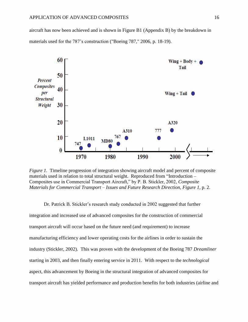
Figure 1 shows the progression of composite material integration by aircraft model and
percentage of use in relation to structural weight (Stickler, 2002, figure 1). With Boeing’s recent
integration of advanced composites in primary structures construction (wings and fuselage) for
the 787 Dreamliner, the industry’s first full structural integration for a commercial transport
APPLICATION OF ADVANCED COMPOSITES 16
aircraft has now been achieved and is shown in Figure B1 (Appendix B) by the breakdown in
materials used for the 787’s construction ("Boeing 787," 2006, p. 18-19).
Figure 1. Timeline progression of integration showing aircraft model and percent of composite
materials used in relation to total structural weight. Reproduced from “Introduction –
Composites use in Commercial Transport Aircraft,” by P. B. Stickler, 2002, Composite
Materials for Commercial Transport – Issues and Future Research Direction, Figure 1, p. 2.
Dr. Patrick B. Stickler’s research study conducted in 2002 suggested that further
integration and increased use of advanced composites for the construction of commercial
transport aircraft will occur based on the future need (and requirement) to increase
manufacturing efficiency and lower operating costs for the airlines in order to sustain the
industry (Stickler, 2002). This was proven with the development of the Boeing 787 Dreamliner
starting in 2003, and then finally entering service in 2011. With respect to the technological
aspect, this advancement by Boeing in the structural integration of advanced composites for
transport aircraft has yielded performance and production benefits for both industries (airline and
APPLICATION OF ADVANCED COMPOSITES 17
aerospace) such as increased fuel efficiency due to the reduction of airframe weight, and the
utilization of bonded joints in the manufacturing process (reducing the number of mechanical
fasteners) which lowers the assembly cost. Enabling this technology has also created challenges
such as focusing on new research and development efforts that create low-cost products,
automated processes, new analysis methods, and the establishment of certification requirements
in order to utilize advanced composites for the construction of transport aircraft (Stickler, 2002).
To derive maximum benefit from advanced composite technology as its use increases within the
aerospace industry will require continued research and critical analysis of milestone structural
integration that exists and is being actively applied with aircraft such as the 787 by developing
(and sharing) best practice methods throughout the industry.
Passenger Confidence
Will people feel safe flying on a commercial transport aircraft that is constructed with
composite materials? This is certainly a question that Boeing had to consider in 2003 when
development of the 787 began. If queried, the general population would not know the difference
between a traditionally constructed aircraft (mostly aluminum) such as the 737 versus the 787
(mostly composite) until the material and construction differences are explained in detail.
Hypothetically, if both aircraft were placed side-by-side at an airport, airline passengers would
make a typical comparison based on both aircraft being relatively the same shape and form
without much consideration given to the materials that they are constructed from. Are they
concerned with or do they really care about the materials used? The most likely response (if
asked) would be “no” based on the aforementioned hypothetical scenario. Their biggest concern
will be safety. When contrasting the 787 with a traditionally constructed commercial transport
aircraft, the Boeing 737 is the most widely used commercial aircraft in the world that has a
APPLICATION OF ADVANCED COMPOSITES 18
proven safety record. This proven reliability instills a sense of security and confidence that
makes passengers feel safe (Wells & Rodrigues, 2004).
Unfortunately, building passenger confidence in the first composite aircraft is on hold
due to the present grounding of all Boeing 787s for lithium-ion battery modification and re-
certification at the time this paper was written. With respect to the social aspect, even though the
787 battery issue has caused a lengthy and costly grounding period for Boeing, immediate
passenger concern will be the safe return-to-flight of all 787s which will be accomplished
through rigorous testing and re-certification to prove that this aircraft is once again safe and
reliable (Wells & Rodrigues, 2004). After the 787 is re-certified by the FAA and given the green
light to resume service, passenger concern (or social impact) regarding the confidence in
composite construction will be negligible (non-existent) unless a problem arises that is specific
to a composite component on the 787 found by Boeing or an operator (Garland, Wise, & Hopkin,
1999). Future research of this topic after sustained in-service time of the Boeing 787 would
reveal an accurate representation of the social impact of composite commercial transport aircraft.
Environmental Impact
As previously mentioned, one of the primary advantages of increasing the use of
composite materials for the construction of commercial transport aircraft is the parallel increase
in aircraft performance due to the overall weight savings that are intrinsic to composites.
Another intrinsic benefit previously mentioned is the increase in the manufacturing efficiency by
reducing the overall part and fastener count through the use of secondary bonding (co-curing and
co-bonding) techniques (Stickler, 2002) that exemplifies the lean manufacturing process which
creates less waist in order to decrease manufacturing costs while simultaneously reducing
environmental impact (U.S. Environmental Protection Agency [EPA], 2000).
APPLICATION OF ADVANCED COMPOSITES 19
By reducing the weight of an aircraft, less fuel burn is required during all phases of flight
(takeoff, cruise, and landing) which immediately decreases the aircraft’s CO2 and noise footprint
on the environment due to the use of reduced engine power (Fielding, 1999). For every barrel of
crude oil that is refined, jet fuel (kerosene) is the third largest (by volume) refined output
(approximately 4.2 gallons) per barrel (42 U.S. gallons) with gasoline as the highest (19.3
gallons) and diesel/home fuel oil being the second highest at 9.8 gallons ("Oil: petroleum
products," “n.d.”). With jet fuel being the third highest output of crude oil refinement, it is no
surprise that the airline industry is the largest consumer of jet fuel which equates to
approximately 30% of a typical airline’s operating cost according to Airlines for America ("High
airline costs," 2012). With respect to the environmental aspect, the immediate desire and need to
decrease fuel operating costs with the use of more efficient composite aircraft in order to sustain
the airline industry will have an immediate impact on the environment by reducing its
dependency on fossil fuels which will lower emissions to help sustain the environment.
Regulatory Methodology
Dr. Stickler’s research on the growth and increased use of composite materials in the
aerospace industry conducted in 2002 states:
The approach for composite and metallic materials involves analysis supported by
coupon thru component level test evidence. Analysis approaches and structural testing is
performed in compliance with FAA/JAA regulations. The “analysis supported by test
evidence” approach is accomplished by establishing material allowables, performing
element level tests on structural details such as joints, subcomponent, and full-scale
component level tests on wings, fuselage barrel sections and horizontal and vertical
stabilizers (Stickler, 2002, p. 2).
APPLICATION OF ADVANCED COMPOSITES 20
This methodology supports current FAA guidance for the certification of composite
aircraft (as previously discussed) and was first used and evidentiary in Boeing’s approach with
early composite certification for the 777 that included static and fatigue full-scale testing of the
horizontal and vertical stabilizers which are constructed with advanced composites (Stickler,
2002).
The FAA realized the need for continued improvement and development of the
certification process for composite materials used in the aerospace industry based on increased
use by aerospace manufacturers for the construction of Part 25 commercial transport aircraft by
forming the Joint Advanced Materials & Structures Center of Excellence (JAMS) in 2003 for the
Air Transportation Centers of Excellence under the Federal Aviation Administration Research,
Engineering and Development Authorization Act of 1990 ("FAA Creates Center of Excellence,"
n.d.). The center’s primary focus is on “the safety and certification of existing and emerging
applications of composites and advanced materials in commercial transport aircraft.” ("FAA
Creates Center of Excellence," n.d., About Us).
In September of 2011, the U.S. Government Accountability Office published its own
independent report on the safety of composite commercial transport aircraft in order to review
FAA and EASA certification processes based on the safety concerns associated with transport
aircraft constructed primarily with composite materials in structural areas (wings and fuselage)
for the Boeing 787, which is the first large commercial transport aircraft to undergo this
certification process (U.S. Government Accountability Office [GAO], 2011). The findings of
this report will be discussed later, and presented in the meta-analytic review section of this
project. With respect to the political aspect, this GAO report is a prime example of government
oversight for the purpose of checks and balances within its own (and joint) administrations in
APPLICATION OF ADVANCED COMPOSITES 21
order to verify that the process of certification and all applicable standards of regulation have
been adhered to.
The Human Factors Associated with Composite Repair and Maintenance
Component Failure
According to Mr. Kenneth Cooper2 and Mr. Timothy Moore of the U.S. Navy’s Fleet
Readiness Center Southwest Advanced Composite Repair School at Naval Air Station North
Island, California, advanced composite component failure due to substandard repair is probable
and likely to occur based on lack of experience and the complexity of the repair procedures (K.
Cooper, personal communication, December 3, 2012). All repair procedures for advanced
composite components used in structural and high-load applications are extremely complex and
difficult to master. Special care and extreme attention-to-detail must be maintained throughout
the entire repair process in order to comply with the strict guidelines and procedures as
prescribed in the applicable structural repair manual (SRM). If not followed correctly,
significant change in part stiffness could cause excessive part deflection, improper function, and
dynamic instability which could lead to structural failure (Naval Air Systems Command
[NAVAIR], 2011).
With respect to unsafe acts, regardless of either intentionally or unknowingly performing
improper composite repair, the resulting effects will increase the probability of components
returned to service that are insufficiently capable of handling their designed load tolerances
which could lead to structural or catastrophic failure (NAVAIR, 2011).
[2] Mr. Kenneth Cooper is a Master Composite Materials Repair Artisan and Advanced
Composites Work Leader/Training Instructor, and Mr. Timothy Moore is the Training
Specialist/Master Composite Materials Repair Artisan at FRCSW, NAS North Island, CA.
APPLICATION OF ADVANCED COMPOSITES 22
Composite Repair Methods
According to Dr. Lamia Salah of the National Institute for Aviation Research at Wichita
State University, current composite repair at the depot level (airline maintenance) is deficient in
the areas of composite repair technician training and quality control (Salah, 2013). Dr. Salah’s
research and findings will be presented in the meta-analytic review section of this project. While
Dr. Salah’s research of airline composite maintenance practices revealed severe deficiencies in
the areas of training and quality control, original equipment manufacturer (OEM) in-house
practices by Boeing are currently being reviewed for training standardization according to Ms.
Holly Thomas of the Boeing Company (H. Thomas, personal communication, April 9, 2013).
Based on these observations, the attitudes aspect of human factors regarding the repair and
maintenance methods for composite materials may indeed have a very strong impact on the
quality of repairs being carried out on all levels (Hawkins, 1993). With the advent of composite
commercial transport aircraft, in-service damage will occur and will need to be effectively
repaired. As previously discussed, due to the critical nature of composite repair, it is imperative
that the repair methods used (at every level) are standardized throughout the industry. Based on
Dr. Salah’s research, this concern validates the need for further research of this topic in order to
actively engage all applicable industry professionals for the development of standardized repair
and maintenance methods/procedures for composite materials used in the aerospace industry.
Artisan Training and Experience
As previously mentioned, the SRM procedures for repairing advanced composites are
extremely difficult and require extensive training and practice in order to become proficient with
the many complex repair procedures. Some of the common types of advanced composite field
repairs that are taught by the U.S. Navy include bonded repairs such as standard wet layups,
APPLICATION OF ADVANCED COMPOSITES 23
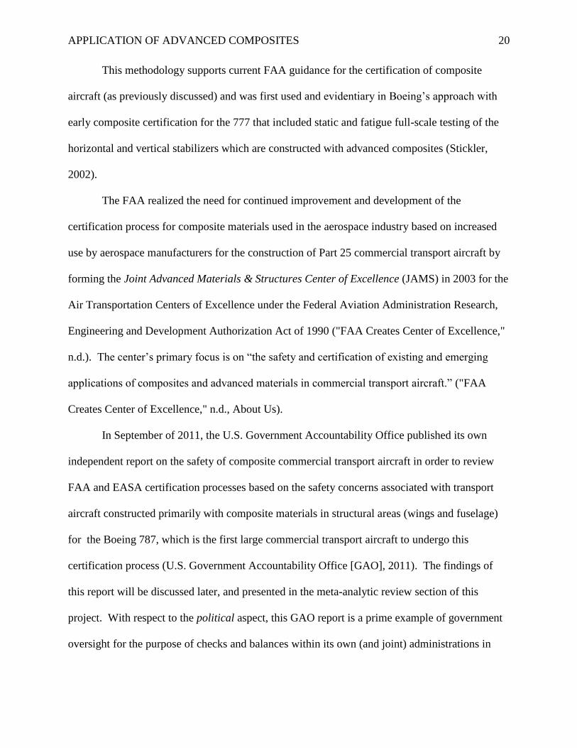
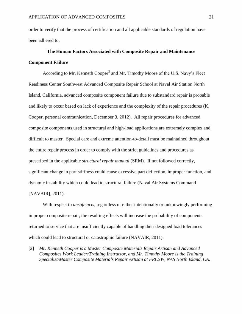
double vacuum debulk (DVD) wet layup, delamination/disbond repair, pre-cured patch repair,
and substructure (honeycomb) repairs (NAVAIR, 2011). Refer to Figures 2-5 for an illustration
of the DVD advanced composite repair method. With respect to the human limitations aspect, it
cannot be overstated that mastery and proficiency of these repair methods and procedures will be
critical in order for the repair to be correct and free of defects. Without proper training,
experience, and proficiency, the probability of error will be much greater (Garland, Wise, &
Hopkin, 1999).
Figure 2 Figure 3
Figure 4 Figure 5
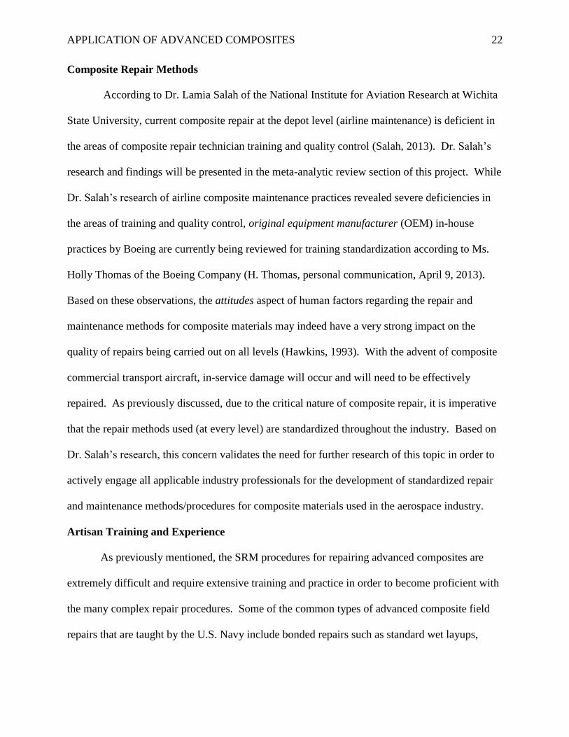
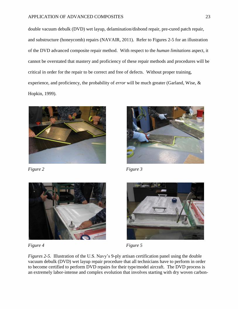
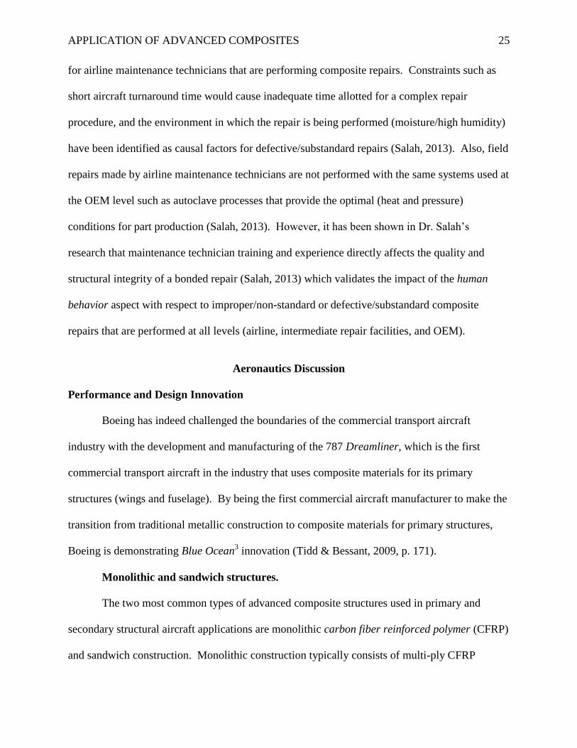
Figures 2-5. Illustration of the U.S. Navy’s 9-ply artisan certification panel using the double
vacuum debulk (DVD) wet layup repair procedure that all technicians have to perform in order
to become certified to perform DVD repairs for their type/model aircraft. The DVD process is
an extremely labor-intense and complex evolution that involves starting with dry woven carbon-
APPLICATION OF ADVANCED COMPOSITES 24
fiber fabric ply preparation/fiber orientation, and then laying up each ply in the correct
orientation after resin impregnation (Figures 2-3). The 9-ply laminate is then placed on a double
vacuum bench for heat curing (Figures 4-5). The DVD method was developed by the U.S. Navy
(NAWC Warminster) to produce superior repairs in order to eliminate porosity (small voids) that
cause strength degradation (NAVAIR, 2011). Photos provided by K. Cooper, U.S. Navy.
The U.S. Navy has multiple levels of repair artisan training with proficiency standards in
order to become a qualified composite repair technician. After the technician receives artisan
training, proficiency must be maintained through practical repair experience. If proficiency (by
making frequent repairs) is not maintained, the artisan’s skills will diminish over time and repeat
proficiency training may be required depending on the time lapse between repairs. This
information suggests that the U.S. Navy’s standard of training and certification for composite
repair could be used as a model program for standardization throughout the aerospace industry.
Non-Standard Repairs and Maintenance Malpractice
For the purpose of discussion, it is assumed that aircraft maintenance technicians
(AMTs) would not intentionally or maliciously perform composite repair incorrectly based on
the potential results of that human behavior; possible catastrophic failure with loss of life
(Garland et al., 1999). Based on the previous statement, then any (or all) defective composite
repairs can be attributed to either maintenance malpractice or the environmental condition at the
time of repair (Salah, 2013). When considering the malpractice factors for improper/non-
standard or substandard composite repair (excluding intentional acts), SRM procedural violations
due to unfamiliarity (lack of proper training), or non-use of SRM procedures stand out as the
cause of malpractice.
As previously discussed, performing bonded repairs on advanced composites used in
structural applications is complex and also time-consuming; if performed incorrectly, the
likelihood of structural failure is high. Conditions for field repairs may not always be adequate
APPLICATION OF ADVANCED COMPOSITES 25
for airline maintenance technicians that are performing composite repairs. Constraints such as
short aircraft turnaround time would cause inadequate time allotted for a complex repair
procedure, and the environment in which the repair is being performed (moisture/high humidity)
have been identified as causal factors for defective/substandard repairs (Salah, 2013). Also, field
repairs made by airline maintenance technicians are not performed with the same systems used at
the OEM level such as autoclave processes that provide the optimal (heat and pressure)
conditions for part production (Salah, 2013). However, it has been shown in Dr. Salah’s
research that maintenance technician training and experience directly affects the quality and
structural integrity of a bonded repair (Salah, 2013) which validates the impact of the human
behavior aspect with respect to improper/non-standard or defective/substandard composite
repairs that are performed at all levels (airline, intermediate repair facilities, and OEM).
Aeronautics Discussion
Performance and Design Innovation
Boeing has indeed challenged the boundaries of the commercial transport aircraft
industry with the development and manufacturing of the 787 Dreamliner, which is the first
commercial transport aircraft in the industry that uses composite materials for its primary
structures (wings and fuselage). By being the first commercial aircraft manufacturer to make the
transition from traditional metallic construction to composite materials for primary structures,
Boeing is demonstrating Blue Ocean3 innovation (Tidd & Bessant, 2009, p. 171).
Monolithic and sandwich structures.
The two most common types of advanced composite structures used in primary and
secondary structural aircraft applications are monolithic carbon fiber reinforced polymer (CFRP)
and sandwich construction. Monolithic construction typically consists of multi-ply CFRP
APPLICATION OF ADVANCED COMPOSITES 26
laminate panels that are used for a variety of aircraft parts and components such as panels,
structural parts, and entire fuselage sections (Boeing 787) as illustrated and explained further in
Figures B4-B7 (Appendix B). Advanced composite sandwich construction typically consists of
a honeycomb core made from aluminum that is covered with two (top and bottom) carbon fiber
face sheets bonded to the core with an adhesive in order to create a high-strength and light-
weight structure that is used for control surfaces, wings, and the empennage where greater
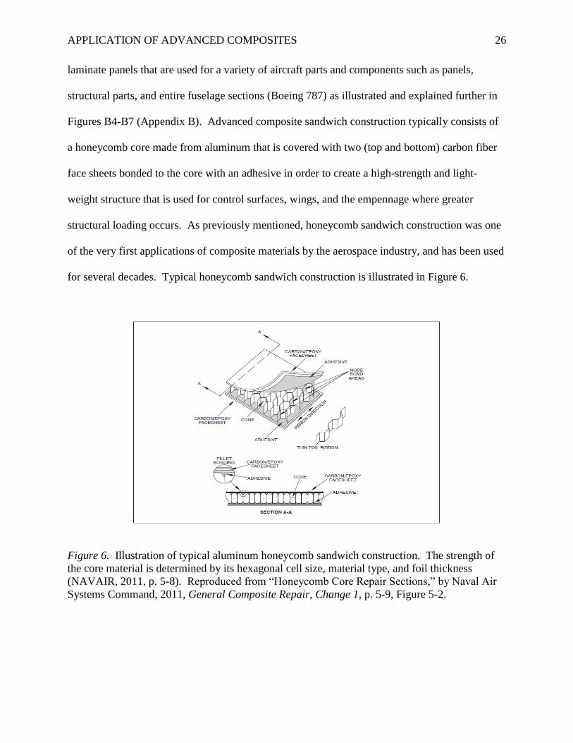
structural loading occurs. As previously mentioned, honeycomb sandwich construction was one
of the very first applications of composite materials by the aerospace industry, and has been used
for several decades. Typical honeycomb sandwich construction is illustrated in Figure 6.
Figure 6. Illustration of typical aluminum honeycomb sandwich construction. The strength of
the core material is determined by its hexagonal cell size, material type, and foil thickness
(NAVAIR, 2011, p. 5-8). Reproduced from “Honeycomb Core Repair Sections,” by Naval Air
Systems Command, 2011, General Composite Repair, Change 1, p. 5-9, Figure 5-2.
APPLICATION OF ADVANCED COMPOSITES 27
Performance benefits through improved design characteristics.
The immediate performance benefit gained from using composite materials for the
construction of commercial transport aircraft (or any aircraft) is the reduction in airframe weight
due to the light-weight characteristics of composites which increases the overall efficiency of the
aircraft. The 787 nets close to 20% weight savings with the use of composite materials when
compared to a traditional metallic airframe of roughly the same size ("Boeing 787," 2006). This
increase in efficiency will translate into fuel savings; one of the key performance benefits that
the operators (airlines) will desire in order to lower their operating costs. Another major benefit
of using composite materials is the relative ease in creating unlimited design configurations that
contain complex shapes and curves which is more difficult, time-consuming, and costly with
traditional metallic aircraft construction (Stickler, 2002). This can be seen by the elegant
features of the Boeing 787 Dreamliner as illustrated in Figures B2 and B3 (Appendix B), paying
close attention to the shape of the wings, the curves for the blended wing tips and vertical
stabilizer, and the smooth transition of the nose and cockpit. This is due in part to the autoclave
manufacturing process associated with composite materials that allow parts and components to
be molded into almost any shape which yield high strength and stiffness for aerospace
applications. With respect to the topic of advanced aerodynamics, the use of composite
materials for the manufacturing of transport aircraft that utilize complex shapes and curves in
their design will create a more efficient streamlined aircraft design. This streamlined design
(through the use of complex shapes and curves) will also increase the aircraft’s aerodynamic
efficiency by increasing the laminar characteristics (decreasing turbulent airflow) which will
lower the drag coefficient (cd) due to the unlimited shape possibilities of composite materials that
effectively create a streamlined design (Anderson, 2008). This increase in aerodynamic
APPLICATION OF ADVANCED COMPOSITES 28
efficiency combined with the weight savings gained through the use of composite materials
decreases the aircraft fuel burn rate, making the Boeing 787 20% more fuel efficient when
compared to a traditional commercial aircraft of the same size (The Boeing Company, n.d.).
[3] Blue Ocean innovation represents all potential markets which currently do not exist and
must be created. (Tidd & Bessant, 2009, p. 171)
Fatigue Life and Failure Mode
Another intrinsic characteristic and benefit of composite materials is improved fatigue
performance over metallic structures which will increase airframe service life and reduce
maintenance costs (Stickler, 2002, p. 2). However, the poor out-of-plane load transfer
characteristics of composite materials have proven to be challenging for engineers to predict and
accurately model failure mode. Due to the complex nature of the failure modes associated with
composite materials, extensive non-destructive inspection (NDI)4 testing is required to detect the
flaw growth within a composite component (Seneviratne, 2008). In Mr. Waruna Seneviratne’s
research for the National Institute for Aviation Research (NIAR), it was found that even though
the loading and failure modes for composite commercial transport aircraft structures are
significantly different, current certification programs use the load-life factors generated by the
U.S. Navy’s F/A-18 program (Seneviratne, 2008, p. 2) based on the fact that these are the only
known load-life factors for composite materials structural applications. Mr. Seneviratne’s
primary research objective suggested a probabilistic approach to synthesize life factor, load
factor, and damage in composite structures to determine fatigue life (Seneviratne, 2008, p. 3).
Modeling and simulation systems.
Some of the modeling and simulation systems used to predict fatigue and failure mode in
composite materials include: double cantilever beam (DCB), four points end notched flexure
APPLICATION OF ADVANCED COMPOSITES 29
(4ENF), 3D plane strain modeling, and finite element analysis (FEA). The most common and
robust FEA simulation system currently being used in the aerospace industry for composite
materials is SIMULIA Abaqus developed by Dassault. Abaqus performs virtual tests with
realistic simulation which helps reduce product development time and costs while improving
reliability (Dassault Systemes, n.d.). According to Dr. Ernest L. Roetman5, robust simulation
modeling in-conjunction with new research and approaches to theoretical problem-solving will
be required for the development of new non-destructive testing (NDT) computational methods
that address the dynamic problems of anisotropic6 materials in order to effectively create new
analysis tools for the prediction of composite materials fatigue and failure mode (E. L. Roetman,
personal communication, April 16, 2013).
[4] The NDI method most commonly used to detect damage in aerospace composite
components is pulse-echo ultrasonic (UT) scanning. (Buckley, 2006)
[5] Dr. Ernest L. Roetman is an Adjunct Professor for ERAU Worldwide and is recognized as
one of the leading professionals in the field of non-destructive testing for composite
materials.
[6] Anisotropic properties (dependent/differs based on direction) are common to composite
materials due to the multi-directional fiber construction which exhibits different or varying
properties depending on the axis or plane. (NDT Education Resource Center, n.d.)
Lightning Strike Protection
Lightning is a discharge of electricity (giant spark) that is typically associated with a
thunderstorm that can occur inside a cloud, from cloud to cloud, from a cloud to the air, or from
a cloud to the ground (Ahrens, 2009, p. 389). The destructive nature of the electrical current and
heat associated with a lightning strike (around 54,000°F) posses a significant threat to composite
materials used in aerospace applications due to their poor electrical conductivity characteristics
and susceptibility to weaken when exposed to high heat. Traditionally constructed aircraft with
metallic (aluminum) airframes are excellent conductors of electricity which will allow the
electrical discharge of a lightning strike to flow through and exit as if it were a piece of wire; the
APPLICATION OF ADVANCED COMPOSITES 30
metallic airframe is simply completing the electrical circuit (Severson, 2012). The following is
true for a metallic aircraft provided that the entire airframe is electrically bonded:
As long as the electrical circuit is not interrupted (does not encounter resistance), the
lightning strike will be able to flow through the external skin of the aircraft without
causing any damage. Poorly fastened joints or gaps could cause arcing and burning when
the electrical current from the lightning strike tries to continue its path by jumping to the
closest piece of metal (Severson, 2012, p. 8).
To clarify and emphasize this point, if electrical bonding is maintained throughout the metallic
airframe and metallic aircraft skin, the aircraft should be sufficiently protected from a lightning
strike and simply act as a large electrical circuit. The same holds true for a composite aircraft
with some differences. The FAA’s AC 20-107B, Composite Aircraft Structure, under part 11
(Additional Considerations), subpart (c) Lightning Protection states:
Lightning protection design features are needed for composite aircraft structures. Current
carbon fiber composites are approximately 1,000 times less electrically conductive than
standard aluminum materials, and composite resins and adhesives are traditionally non-
conductive. Glass and aramid fiber composites are non-conductive. A lightning strike to
composite structures can result in structural failure or large area damage, and it can
induce high lightning current and voltage on metal hydraulic tubes, fuel system tubes,
and electrical wiring if proper conductive lightning protection is not provided (FAA,
2009, para. (c), p. 26).
As AC 20-107B recognizes, composite materials (fibers, resins, and adhesives) are non-
conductive and must be given conductive properties in order to be adequately protected and to
protect critical aircraft systems (hydraulic, fuel, and electrical) from the potential catastrophic
APPLICATION OF ADVANCED COMPOSITES 31
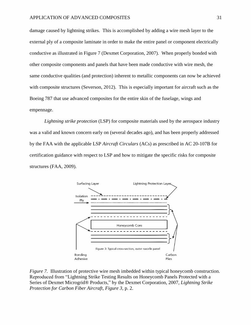
damage caused by lightning strikes. This is accomplished by adding a wire mesh layer to the
external ply of a composite laminate in order to make the entire panel or component electrically
conductive as illustrated in Figure 7 (Dexmet Corporation, 2007). When properly bonded with
other composite components and panels that have been made conductive with wire mesh, the
same conductive qualities (and protection) inherent to metallic components can now be achieved
with composite structures (Severson, 2012). This is especially important for aircraft such as the
Boeing 787 that use advanced composites for the entire skin of the fuselage, wings and
empennage.
Lightning strike protection (LSP) for composite materials used by the aerospace industry
was a valid and known concern early on (several decades ago), and has been properly addressed
by the FAA with the applicable LSP Aircraft Circulars (ACs) as prescribed in AC 20-107B for
certification guidance with respect to LSP and how to mitigate the specific risks for composite
structures (FAA, 2009).
Figure 7. Illustration of protective wire mesh imbedded within typical honeycomb construction.
Reproduced from “Lightning Strike Testing Results on Honeycomb Panels Protected with a
Series of Dexmet Microgrid® Products,” by the Dexmet Corporation, 2007, Lightning Strike
Protection for Carbon Fiber Aircraft, Figure 3, p. 2.
APPLICATION OF ADVANCED COMPOSITES 32
Industry Concerns
Validation testing and load data.
When discussing the topic of aircraft and spacecraft development, any newly developed
aircraft will have system validation concerns that are identified and must be addressed (proven
reliable) through proper testing (Fielding, 1999). With respect to the first large-scale application
of composite materials for primary structures (fuselage and wings) for a commercial transport
aircraft, structures validation (for certification) must be performed through coupon testing.7
However, since there is no pre-existing load data for such an aircraft, actual in-service load data
collection may be required in order to correct possible deficiencies that could not be produced
during developmental simulation due to a lack of proven data for load enhancement factor
(LEF)8 computation (FAA, 2009). In-service structural health monitoring (SHM) for large-scale
composite transport aircraft will be vital for the collection of working load data in order to
accurately compute LEF for future applications (Stickler, 2002).
The utilization of structural health monitoring (SHM) for load monitoring.
Structural health monitoring (SHM) has been used in the aerospace industry for several
decades through many different techniques that include simple strain gauges affixed to load-
bearing structures, to more advanced devices such as piezoelectric actuators/sensors called
SMART Layers™ that can be surface-mounted or embedded within the structure (Lin, Qing,
Kumar, & Beard, 2005) similar to a wire mesh layer as previously discussed for lightning strike
protection. Current piezoelectric devices such as SMART Layers™ and the SMART Suitcase™
that have been developed by Acellent Technologies, Inc. are extremely sensitive and robust
systems of load measurement that have been proven reliable in several aerospace applications
(Acellent Technologies, Inc., n.d.). The current applications of this technology for composite
APPLICATION OF ADVANCED COMPOSITES 33
structures are: sub-surface damage detection (delaminations), hot-spot monitoring and crack
detection, impact detection, and in-flight load monitoring (Acellent Technologies, Inc., n.d.). All
of these are critical concerns for large composite structures that have been identified throughout
the industry for composite transport aircraft applications. Advancements in SHM and non-
destructive testing (NDT) technology will also be required in order to keep up with industry use
by developing new and more efficient/accurate methods of monitoring and testing that will
provide the empirical data needed for future applications (Stickler, 2002). One such
advancement for SHM that is currently being researched by Mr. Peter Osterc9 proposes the use
of phased array beam-steering10
for guided wave structural health monitoring by developing a
new beam-forming algorithm that is specific to composite materials (Osterc, Kim, & Yoo, 2012).
This type of research is indicative of observed advancement needs that address developmental
process improvements directed towards existing material concerns for the continued use of
advanced composites in the aerospace industry.
FAA methodology and GAO safety concerns.
As previously discussed, the FAA has been taking a very proactive approach in
collaborating with industry leaders to address the concerns with the expanded use of composite
materials in the aerospace industry by sponsoring research organizations such as the Joint
Advanced Materials & Structures Center for Excellence (JAMS), and the Commercial Aircraft
Composite Repair Committee (CACRC) which is responsible for the development of improved
maintenance, inspection, and repair of commercial aircraft composite structures and components
(GAO, 2011, p. 34). The 2011 GAO report Status of FAA’s Actions to Oversee the Safety of
Composite Airplanes stated the following regarding safety concerns specific to composite repair
and maintenance:
APPLICATION OF ADVANCED COMPOSITES 34
On the basis of expert interviews and a review of literature, GAO identified four key
safety-related concerns with the repair and maintenance of composites in commercial
airplanes – (1) limited information on the behavior of airplane composite structures,
(2) technical issues related to the unique properties of composite materials,
(3) standardization of repair materials and techniques, and (4) training and awareness.
None of the experts believed these concerns posed extraordinary safety risks or were
insurmountable. FAA is taking action to help address these concerns identified by GAO
related to the repair and maintenance of composite airplane structures. However, until
these composite airplanes enter service, it is unclear if these actions will be sufficient
(GAO, 2011, para. What GAO Found).
Based on this information and recent research presented by Dr. Lamia Salah (CACRC
Committee Member), it is apparent that the industry concern of commercial aircraft composite
maintenance and repair is sufficiently valid and must be addressed, but also suggests that it is too
early for assessment of this concern based on the lack of in-service time of composite aircraft.
Composite materials fire safety concern.
Fire safety for large composite commercial transport aircraft such as Boeing’s 787 has
been a valid concern since its initial development with respect to crashworthiness and passenger
safety due to the flammability of the components used for composite materials (fiber, resins, and
adhesives). Most composite materials in their raw form are vulnerable (can weaken) when
exposed to high-heat and are less fire resistant than traditional metallic structures if a protective
coating is not used (Ohlemiller & Shields, 1998). The FAA was aware of this safety hazard with
the early use of composite materials for air transport applications and implemented extensive
guidelines under AC 20-170B Composite Aircraft Structure that addresses the mitigation
APPLICATION OF ADVANCED COMPOSITES 35
required for proper fire protection which initially states under part 11 (Additional
Considerations) subsection (b) Fire Protection, Flammability and Thermal Issues:
(1) Fire and exposure to temperatures that exceed maximum operating conditions require
special considerations for composite airframe structure. (Refer to note below)
Requirements for flammability and fire protection of aircraft structure attempt to
minimize the hazard to occupants in the event that flammable materials, fluids, or vapors
ignite. The regulations associated with each aircraft product type (i.e., transport, small
airplane, rotorcraft) should be used accordingly. Compliance may be shown by tests or
analysis supported by test evidence. A composite design, including repair and
alterations, should not decrease the existing level of safety relative to metallic structure.
In addition, maintenance procedures should be available to evaluate the structural
integrity of any composite aircraft structures exposed to fire and temperatures above the
maximum operating conditions substantiated during design (FAA, 2009, para. (b), p. 24).
Note: Aircraft cabin interiors and baggage compartments have been areas of
flammability concerns in protecting passenger safety. This revision of the AC
does not address composite materials used in aircraft interiors and baggage
compartments. Please consult other guidance material for acceptable means of
compliance with flammability rules for interiors.
Boeing 787 special conditions.
In the previously discussed GAO report that addresses composite aircraft safety concerns,
the FAA required Boeing to conduct fire tests as delineated in AC 20-170B for the certification
of the fuselage and wings as outlined in Table 1. This special condition testing was performed
in-part by Boeing Aircraft Rescue and Firefighting (ARFF) professionals in June of 2012 with
conclusive results that showed the 787’s combustion hazard was similar to that of a metallic
structured aircraft, and that the toxicity levels of the 787’s skin panels were also similar to that of
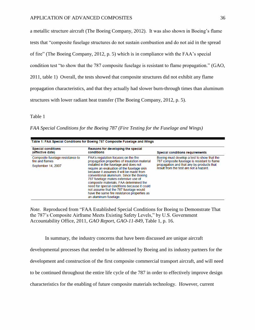
APPLICATION OF ADVANCED COMPOSITES 36
a metallic structure aircraft (The Boeing Company, 2012). It was also shown in Boeing’s flame
tests that “composite fuselage structures do not sustain combustion and do not aid in the spread
of fire” (The Boeing Company, 2012, p. 5) which is in compliance with the FAA’s special
condition test “to show that the 787 composite fuselage is resistant to flame propagation.” (GAO,
2011, table 1) Overall, the tests showed that composite structures did not exhibit any flame
propagation characteristics, and that they actually had slower burn-through times than aluminum
structures with lower radiant heat transfer (The Boeing Company, 2012, p. 5).
Table 1
FAA Special Conditions for the Boeing 787 (Fire Testing for the Fuselage and Wings)
Note. Reproduced from “FAA Established Special Conditions for Boeing to Demonstrate That
the 787’s Composite Airframe Meets Existing Safety Levels,” by U.S. Government
Accountability Office, 2011, GAO Report, GAO-11-849, Table 1, p. 16.
In summary, the industry concerns that have been discussed are unique aircraft
developmental processes that needed to be addressed by Boeing and its industry partners for the
development and construction of the first composite commercial transport aircraft, and will need
to be continued throughout the entire life cycle of the 787 in order to effectively improve design
characteristics for the enabling of future composite materials technology. However, current
APPLICATION OF ADVANCED COMPOSITES 37
research has identified that composite maintenance and repair is an observed limitation that
exists within the industry which may cause future safety concerns regarding the continued use of
advanced composites for commercial transport aircraft. With respect to the sustainability of
advanced composites used for structural applications within the aerospace industry for Part 25
aircraft, continued in-service time will be required to fully assess the adequacy of current actions
and to allow for the identification and correction of unexpected deficiencies that may occur.
[7] Composite coupon testing is a small test specimen (e.g., usually a flat laminate) for
evaluation of basic lamina or laminate properties or properties of generic structural
features (e.g., bonded or mechanically fastened joints). (FAA, 2009, Appendix 2)
[8] Load (or Life) Enhancement Factor (LEF) is an additional load factor and/or test duration
applied to structural repeated load tests, relative to the intended design load and life
values, used to account for material variability. It is used to develop the required level of
confidence in data. (FAA, 2009, Appendix 2)
[9] Mr. Peter Osterc is a Graduate Student at Embry-Riddle Aeronautical University’s
Department of Aerospace Engineering, Daytona Beach, Florida.
[10] Electronic beam-steering is a method of non-destructive evaluation (NDE) developed and
used for metals. (NDT Education Resource Center, n.d.)
Maintenance and Repair Standardization
When discussing and applying the topic of crew resource management (CRM) for
composite repair standardization, teamwork and organizational factors will dictate how standard
operating procedures (SOPs) are formed which will directly impact the safe maintenance of
composite transport aircraft (Kanki, Helmreich, & Anca, 2010). As previously discussed,
composite repair and maintenance was found to be a valid safety concern in the GAO report that
addressed composite aircraft safety. Both the GAO report and Dr. Lamia’s research show that
there is an immediate need for standardization of composite repair throughout the aerospace
industry with specific concentration at the airline level on training and quality control. Dr.
Lamia has identified that even though the published structural repair manual (SRM) procedures
for specific composite repairs applicable to the type/model aircraft are being utilized (and have
APPLICATION OF ADVANCED COMPOSITES 38
been developed) based on current industry standards and best practice methods, variances in
repair techniques exist between each depot (airline) facility due to a lack of training and
experience (Salah, 2013).
Mitigating composite material repair variance and technician training deficiency at all
levels (OEM, airline, and intermediate) is the mission of the Commercial Aircraft Composite
Repair Committee (CACRC) in order to “reduce the cost of maintaining composite structures
through standardization of materials, technique, and training.” (Commercial Aircraft Composite
Repair Committee [CACRC], n.d., Mission Statement) To date, the CACRC’s repair technique
task group has published eight documents with another six (pending) for the standardization of
common composite repairs such as wet layup and vacuum bagging.
OEM level training development and standardized repairs.
As previously mentioned, Boeing is actively pursuing composite repair training
standardization for all of its manufacturing facilities (commercial and military) which is
currently in the developmental stage according to Ms. Holly Thomas of the Boeing Company (H.
Thomas, personal communication, April 9, 2013). According to Ms. Kirsten Bossenbroek of the
Boeing Company, Boeing’s approach to composite repair standardization for the 787 was the
development and implementation of a quick composite repair (QCR) kit that is used to perform
pre-cured patch repairs (see note) in less than one hour with a cure time of 30 minutes, making
this process/type of composite repair (when applicable) highly beneficial to the airlines for short
maintenance turnarounds in order to reduce aircraft down time. The QCR kit has been
distributed to all 787 operators along with proper training for its use in accordance with the
applicable SRM composite repair procedures for pre-cured patch use (K. Bossenbroek, personal
communication, April 29, 2013).
APPLICATION OF ADVANCED COMPOSITES 39
Note. The utilization of a pre-cured patch repair (while common) may not apply to all composite
repair situations and will depend on the type/severity of damage. With ALL composite damage,
thorough inspection (NDI) must be performed for complete damage assessment (NAVAIR,
2011).
Implementation of organizational crew resource management (CRM).
The concept of CRM can be applied to the problem of composite maintenance and repair
standardization by addressing factors such as organizational cultures and subcultures which are
directly related to the type/style of leadership and mid-level managers (Kanki et al., 2010).
Depending on how well any organization recognizes and deals with these organizational cultures
and subcultures is a direct reflection of that organization’s measure of health with respect to its
safety culture, and the first step to creating a working safety culture is to develop and refine an
organization’s standard operating procedures (SOPs) (Kanki et al., 2010, p. 71).
By taking the basic approach of CRM which is to focus on attitudes, behavior, and
performance, SOP’s can be developed for composite maintenance and repair by creating a
philosophy that states how the organization will conduct their composite maintenance and repair
in a safe and efficient manner that is in compliance with all published procedures and regulations
(Kanki et al., 2010). As composite maintenance and repair will become more common-place for
airline maintenance departments with the arrival of composite commercial transport aircraft such
as the Boeing 787 Dreamliner and the Airbus A350 XWB, a CRM based approach to composite
maintenance and repair standardization can be adopted (and may be needed) in order to create a
working environment that effectively addresses the challenges associated with the safe repair of
advanced composites used in structural applications; in-part due to the complexity of composite
repair procedures and the skill that is required to perform them correctly. This methodology in-
conjunction with the CACRC will prove to be successful for composite repair standardization.
APPLICATION OF ADVANCED COMPOSITES 40
Methodology
Overview
The qualitative meta-analysis performed in this project is divided into three independent
categories (validation testing, certification, and maintenance/repair) for the purpose of grouping
each study used to the applicable category for isolated comparison of each group in order to
validate the hypothesis that industry-wide comprehensive process improvement should be
implemented and maintained for the promulgation of improved structural validation testing,
certification, and standardized repair procedures. The quantitative statistical analysis performed
in this project is accomplished by analyzing the data from specific studies in order to accept or
reject the hypothesis and to answer this project’s research question: are current testing,
certification, and maintenance procedures for advanced composites used in primary and
secondary commercial transport aircraft structures standardized throughout the aerospace
industry and sufficiently capable of detecting damage or component failure? This type of
organizational analysis has been chosen based on the number/type of studies used in order to
effectively extract the information presented in each study for correlation.
Meta-Analytic Review
The studies used for the meta-analysis are identified and listed by category in Table 2.
Summaries of the studies with findings are presented in this section of the project for reader
familiarization and are quoted directly for accuracy. Composite materials study selection was
accomplished by recognizing each study’s applicability to current problems/concerns and needed
research/data that has been identified by regulatory agencies, standards organizations, and
through industry collaboration. The project findings for each study with respect to their overall
impact and effectiveness for each category will be presented in the results section of this paper.
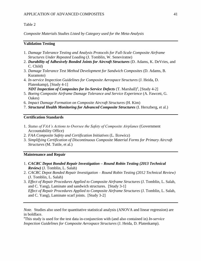
APPLICATION OF ADVANCED COMPOSITES 41
Table 2
Composite Materials Studies Listed by Category used for the Meta-Analysis
Validation Testing
1. Damage Tolerance Testing and Analysis Protocols for Full-Scale Composite Airframe
Structures Under Repeated Loading (J. Tomblin, W. Seneviratne)
2. Durability of Adhesively Bonded Joints for Aircraft Structures (D. Adams, K. DeVries, and
C. Child)
3. Damage Tolerance Test Method Development for Sandwich Composites (D. Adams, B.
Kuramoto)
4. In-service Inspection Guidelines for Composite Aerospace Structures (J. Heida, D.
Platenkamp), [Study 4-1]
NDT Inspection of Composites for In-Service Defects (T. Marshall)a, [Study 4-2]
5. Boeing Composite Airframe Damage Tolerance and Service Experience (A. Fawcett, G.
Oakes)
6. Impact Damage Formation on Composite Aircraft Structures (H. Kim)
7. Structural Health Monitoring for Advanced Composite Structures (I. Herszberg, et al.)
Certification Standards
1. Status of FAA’s Actions to Oversee the Safety of Composite Airplanes (Government
Accountability Office) 2. FAA Composite Safety and Certification Initiatives (L. Ilcewicz) 3. Simplifying Certification of Discontinuous Composite Material Forms for Primary Aircraft
Structures (M. Tuttle, et al.)
Maintenance and Repair
1. CACRC Depot Bonded Repair Investigation – Round Robin Testing (2013 Technical
Review) (J. Tomblin, L. Salah)
2. CACRC Depot Bonded Repair Investigation – Round Robin Testing (2012 Technical Review)
(J. Tomblin, L. Salah)
3. Effect of Repair Procedures Applied to Composite Airframe Structures (J. Tomblin, L. Salah,
and C. Yang), Laminate and sandwich structures. [Study 3-1]
Effect of Repair Procedures Applied to Composite Airframe Structures (J. Tomblin, L. Salah,
and C. Yang), Laminate scarf joints. [Study 3-2]
Note. Studies also used for quantitative statistical analysis (ANOVA and linear regression) are
in boldface. aThis study is used for the test data in-conjunction with (and also contained in) In-service
Inspection Guidelines for Composite Aerospace Structures (J. Heida, D. Platenkamp).
APPLICATION OF ADVANCED COMPOSITES 42
Qualitative Analysis Criterion
Meta-analysis hypothesis validation criterion has been established and simplified for each
category. The criterion is used to specifically evaluate each study (diagnostically) in order to
show hypothesis validation for the purpose of answering this project’s research question. The
specific criterion (arguments) for each category used to evaluate each study are as follows:
Validation Testing – does the study critically investigate (with credible research) to
conclusively prove that the testing methodology presented is needed for standardization within
the industry and/or regulatory agencies and has the potential for implementation?
Certification Standards – does the study critically investigate (with credible research) to
conclusively prove that the certification methodology presented is effective at improving and
standardizing certification processes for the industry and/or regulatory agencies?
Maintenance and Repair – does the study critically investigate (with credible research)
to conclusively prove that the maintenance and repair methodology presented will effectively
create standardization for the industry?
Validation Testing (VT) Studies
VT Study (1).
Damage Tolerance Testing and Analysis Protocols for Full-Scale Composite Airframe Structures
Under Repeated Loading (J. Tomblin, W. Seneviratne)
Summary and findings of the study.
The purpose of this study was to “produce a guideline FAA document, which
demonstrates a “best practice” procedure for full-scale testing protocols for composite airframe
structures with examples.” (Tomblin & Seneviratne, 2008, Presentation p. 2) The primary
objective was to “develop a probabilistic approach to synthesize life factor, load factor and
APPLICATION OF ADVANCED COMPOSITES 43
damage in composite structure to determine fatigue life of a damage tolerant aircraft” by
performing the following:
Demonstrating acceptable means of compliance for fatigue, damage tolerance and static
strength substantiation of composite airframe structures. Evaluating existing analysis
methods and building-block database needs as applied to practical problems crucial to
composite airframe structural substantiation. Investigating realistic service damage
scenarios and the inspection & repair procedures suitable for field practice (Tomblin &
Seneviratne, 2008, p. 3).
The secondary objectives stated for this study are as follows:
Extend the current certification approach to explore extremely improbable high energy
impact threats, i.e. damages that reduce residual strength of aircraft to limit load
capability by investigating realistic service damage scenarios and establishing inspection
& repair procedures suitable for field practice. And to also incorporate certain design
changes into full-scale substantiation without the burden of additional time-consuming
and costly tests (Tomblin & Seneviratne, 2008, p. 3).
The findings of this study revealed the following:
The future need for training and reliable NDI and health monitoring techniques for
damage characterization during full-scale testing and service, as well as focusing further
studies on extremely improbable high energy impact threats and their impact on the
residual strength of the composite structure and inspection intervals (Tomblin &
Seneviratne, 2008, p. 30).
APPLICATION OF ADVANCED COMPOSITES 44
VT Study (2).
Durability of Adhesively Bonded Joints for Aircraft Structures (D. Adams, K. DeVries, and C.
Child)
Summary and findings of the study.
The purpose and objective of this study was to “revisit and revise the Metal Wedge Crack
Durability Test ASTM D3762 in order to consider a reliable method for investigating adhesive
bond durability.” The current test “provides minimal guidance regarding acceptable metal
bonded joints with concerns regarding strength reduction over time due to hydration.” (Adams,
DeVries, & Child, 2011, Presentation p. 3) After the researchers of this study conducted their
literature review and discussions with industry stakeholders, current wedge test potential issues
were identified as the following:
Several aspects of the ASTM D3762 wedge test were identified for experimental
investigation, including methods of specimen manufacturing, testing procedures,
accounting for the failure mode produced (cohesion vs. adhesion), environmental
conditions during testing, and the need for an improved acceptance criterion. Those
aspects associated with specimen manufacturing and the initial test procedure have been
investigated first. Two issues associated with the wedge specimen manufacturing that
were investigated are controlling the bondline thickness and proper machining of the
specimens from the test panel. Additionally, three issues associated with the initial
testing procedures were also investigated concurrently: the method of wedge insertion,
measurement of the initial crack length, and the specimen orientation during testing
(Adams et al., 2011, Abstract).
APPLICATION OF ADVANCED COMPOSITES 45
The findings of this study revealed the following:
Testing was performed using 2024-T3 aluminum specimens bonded using AF 163-2K
adhesive. Test results showed that the method of wedge insertion does affect the initial
crack length, especially for the “weak” bonded specimens. Not only were the initial crack
lengths affected by the method of wedge insertion, but the crack growth and resulting
crack length from five days in ambient air were also affected. While crack growth and
length during environmental exposure varied with surface preparation, specimen
orientation caused no recurring trend in any of the three surface preparation methods
tested to date. Expected benefits to aviation include an improved adhesive bond
durability test method for use in assessing the reliability of adhesively bonded aircraft
structures as well as an FAA Technical Center report to provide additional guidance for
aviation industry users (Adams et al., 2011, Abstract).
VT Study (3).
Damage Tolerance Test Method Development for Sandwich Composites (D. Adams, B.
Kuramoto)
Summary and findings of the study.
The purpose and objective of this study was to “investigate candidate damage tolerance
test methodologies for sandwich composites and to propose specific methodologies for
standardization.” (Adams & Kuramoto, 2012, Abstract) The researchers identified three
candidate test configurations with the following methodologies:
The first methodology utilizes an end loaded compression after impact (CAI) test
configuration. Second, a four-point flexure test methodology has been identified for
evaluating post-impact performance when the damaged facesheet is loaded in
APPLICATION OF ADVANCED COMPOSITES 46
compression. Additionally, a third candidate test method has been developed by the
marine composites community. This test method, based upon ASTM D6416, supports
the damaged sandwich composite panel on the edges and a distributed load is applied by
a bladder until failure. This test methodology is believed to also be of interest for aircraft
applications such as fuselages were pressure loadings are present. A secondary focus of
this investigation is to provide a comparison of residual strength of sandwich composites
obtained using all three of the proposed test methodologies. Initial efforts have focused
on performing a preliminary evaluation of the three candidate damage tolerance test
methodologies using sandwich composites composed of G11 glass/epoxy facesheets and
Nomex honeycomb cores. The three methodologies will be examined for their limits of
applicability and recommended procedures. Additionally, guidance will be established
for interpreting test results and selecting the most appropriate test method for a particular
application (Adams & Kuramoto, 2012, Abstract).
The summary of this study stated the following:
An initial evaluation of the three identified damage tolerance test methodologies is
underway. Impact damage is to be idealized as a circular hole in the upper facesheet to
minimize the variability in test results due to variations in damage states. These tests will
provide an initial comparison of residual strength among the three candidate test
methodologies as well as provide an initial assessment of each test methodology.
Expected benefits to aviation from this research project include the development of
standardized test methodologies for use in assessing the damage tolerance of sandwich
composites used in aircraft structures (Adams & Kuramoto, 2012, p. 12).
APPLICATION OF ADVANCED COMPOSITES 47
VT Study (4-1).
In-service Inspection Guidelines for Composite Aerospace Structures (J. Heida, D. Platenkamp)
Summary and findings of the study.
The purpose and objective of this study was to review “the damage tolerance design
approach for composites and conclude with general guidelines for the in-service inspection of
composite aerospace structures.” (Heida & Platenkamp, 2012, para. 1) This was performed
through the evaluation of carbon fiber reinforced polymer (CFRP) test specimens that are
“representative for primary composite aerospace structures, including relevant damage types
such as impact damage, delaminations and disbonds.” (Heida & Platenkamp, 2012, Abstract)
The following NDI methods were evaluated based on critical aspect:
A range of NDI methods were evaluated such as visual inspection, vibration analysis,
phased array ultrasonic inspection, shearography and thermography inspection.
Important aspects of the evaluation were the capability for defect detection and
characterization, portability of equipment, field of view, couplant requirements, speed of
inspection, and level of training required and the cost of equipment (Heida &
Platenkamp, 2012, Abstract).
The findings of this study revealed the following:
Damage tolerance requirements for composite aerospace structures should be interpreted
so that as long as damage occurring in-service cannot be detected visually, it should not
be structurally significant in the sense that is does not affect the safety during the aircraft
life. In terms of load capability this implies that the damage should never reduce the
structural strength below ultimate load (UL) capability. Only detectable damage may
cause structural degradation below UL (but never below LL, limit load – the maximum
APPLICATION OF ADVANCED COMPOSITES 48
load per fleet lifetime) and should be timely detected by visual inspection or more
advanced NDI methods. The inspection interval should be related to the probability of
damage occurrence, depending e.g. on the structure type. In the period before detection,
any damage should not show significant growth. After detection, the damage should be
repaired to restore UL capability or the component should be replaced. Recommended
NDI methods are automated tap test for detecting relevant impact damage, and ultrasonic
conventional or, preferably, phased array inspection for the detection and characterization
(size, depth) of relevant impact damage, delaminations and disbonds. Shearography and
thermography are considered to be less applicable because of their poor to moderate
defect characterization capabilities, when compared to ultrasonic inspection. But,
thermography and shearography may be optional, non-contact techniques (especially
thermography) for specific inspection configurations such as curved panels and repaired
structures, and for the inspection of specific defect types such as water ingress in
honeycomb structures (Heida & Platenkamp, 2012, para. 5).
VT Study (4-2).
NDT Inspection of Composites for In-Service Defects11
(T. Marshall)
Summary and findings of the study.
The purpose and objective of the aerospace applications section of this study conducted
by Sonatest, Ltd was to show the effectiveness of NDI (C-Scan) for the detection of in-service
BVID (barely visible impact damage) on four separate common advanced composite structures
used in aerospace structural applications using the prescribed impact test protocol under AR-
03/74 Bonded Repair of Composite Aircraft Structures. “Mixed monolithic and sandwich panels
with manufactured defects and controlled energy impacts were tested with the RapidScan™
APPLICATION OF ADVANCED COMPOSITES 49
system.” (Marshall, n.d., Presentation p. 26) The findings of the C-Scan evaluation revealed the
following:
Measurements can be “drawn” onto scan for sizing. The sizes and areas of defects can be
evaluated. Statistical data can assist with the evaluation. Depths of defects are easily
measured. Evaluation results are easily reported. The evaluation can determine volume
of material to repair (Marshall, n.d., Presentation p. 33).
[11] The data from this study was used for ANOVA (2) and will be examined in the next section.
VT Study (5).
Boeing Composite Airframe Damage Tolerance and Service Experience (A. Fawcett, G. Oakes)
Summary and findings of the study.
The purpose and objective of this study was to evaluate “Boeing’s design criteria for
damage tolerant CFRP primary structures and their relationship to maintainability as well as
CFRP structures service experience.” (Fawcett & Oakes, n.d., Outline) The criteria requirements
for barely visible impact damage (BVID) and visual impact damage (VID) are identified as well
as sample damage tolerance for impact by type and location. In-service aircraft (737 and 777)
composite structures are evaluated. The findings of this study revealed the following:
In-service experience with primary composite structure has been excellent. Visual based
inspection program validated. In-service NDT techniques validated. Damage
occurrences are at or below those for equivalent metal structure. Repair techniques have
proven to be effective and efficiently applied (Fawcett & Oakes, n.d., Summary).
APPLICATION OF ADVANCED COMPOSITES 50
VT Study (6).
Impact Damage Formation on Composite Aircraft Structures (H. Kim)
Summary and findings of the study.
The purpose and objective of this study was to investigate the “impact of composite
structures from sources that involve wide area contact due to the tendency to produce internal
damage with little or no exterior visibility.” (Kim, 2012, Abstract) This was accomplished with
the following specific objectives and approach:
Characterize blunt impact threats and locations where damage can occur. Understand
BID formation and visual detectability. Determine key failure modes, phenomena and
parameters by evaluating how failure is affected by bluntness/contact-area, ID & predict
failure thresholds (useful for design), and what conditions relate to development of
significant internal damage with minimal or no exterior visual detectability. Develop
analysis & testing methodologies, and establish new modeling capabilities validated by
tests. The approach uses experiments that are impact representative structure/specimens
wide area high energy blunt impact – e.g., from ground service equipment, high velocity
hail ice impacts – in-flight and ground-hail conditions, internal stiffeners low velocity
impacts – non-deforming impactor, large radius effects. Modeling – nonlinear FEA,
analytical, and to communicate results to industry, collaboration on relevant
problems/projects via workshops and meetings (Kim, 2012, Presentation p. 4).
The findings of this study revealed the following:
Low velocity large radius metal tip impact conclusions: The failure thresholds increase
with both panel thickness and tip radius. The primary forms of damage are surface
denting and delamination, followed by back wall fiber breakage with increasing energy.
APPLICATION OF ADVANCED COMPOSITES 51
Impacts often create a visible surface dent which is more pronounced with the smaller
impact tips than the blunt ones. Dent formation does not necessarily indicate internal
damage. Internal damage can be present without a surface dent and surface dents can be
present without internal damage. Dents measured immediately after the impact event
will be deeper than when measured at another point in the future. The dent relaxes,
decreasing in depth as well as visibility. Large radius metal tips: Deeper understanding
of material behavior subject to impacts, particularly how increased radius affects damage
formation and visual detectability. Establish correlation between the onset of damage
and the radius of the impactor. Determine the relationship between visible damage and
internal damage. Material level test described by failure threshold force results are
applicable to other conditions and specimen configurations (Kim, 2012, p. 53-55).
VT Study (7).
Structural Health Monitoring for Advanced Composite Structures (Herszberg, et al.)
Summary and findings of the study.
The purpose and objective of this study “focuses SHM application to aircraft as a means
of highlighting the issues that face SHM in composite structures, including those in the maritime,
oil and gas, civil infrastructure and other industries.” (Herszberg, Bannister, Li, Thomson, &
White, n.d., Abstract) This is accomplished by “addressing issues involved in the design,
certification, manufacture and through life support of such structures as well as identifying the
critical areas of development to enable the implementation of SHM in future composite aircraft
structures.” (Herszberg et al., n.d., Abstract). The findings of this study revealed the following:
Within the aircraft industry the benefits of SHM relate to the opportunity for reduced
maintenance costs through an adoption of condition based maintenance, together with
APPLICATION OF ADVANCED COMPOSITES 52
reduced aircraft weight and improved performance through more optimized aircraft
design. In order to achieve these goals, research and development is needed in the
following areas: Development of validated post-buckling design and analysis tools to
accurately predict the behavior of thinner, more efficient structures. Material models that
accurately predict damage evolution at high strain levels and under increased through-
thickness stresses, with the possible need to incorporate composite fatigue analysis.
Validated diagnostic systems that can identify the size and location of damage within the
composite structure to the required accuracy. Validated prognosis methodologies to
predict the structural integrity of the damaged structure. Robust techniques for sensor
embedding and connection. Power and data handling equipment compatible with aircraft
on-board systems. Validation of SHM system durability under aircraft service
conditions, including repair or replacement procedures for damaged sensors. Through
dialogue with the airworthiness authorities, SHM has the potential to be accepted within
the aircraft industry. However, addressing the issues raised in this paper needs to be a
focus for future work within the composites and SHM research community if the
acceptance of this technology and its potential benefits are ever to be realized (Herszberg
et al., n.d., para. 7).
APPLICATION OF ADVANCED COMPOSITES 53
Certification Standards (CS) Studies
CS Study (1).
Status of FAA’s Actions to Oversee the Safety of Composite Airplanes (Government
Accountability Office)
Summary and findings of the study.
The purpose and objective of this GAO report was to “review FAA’s and EASA's
certification processes and FAA's oversight of the composite airplanes once they enter service.”
(GAO, 2011, Highlights) The GAO objectively “examined how FAA and EASA assessed the
use of composite materials in the Boeing 787 fuselage and wings, and the extent to which FAA
has addressed safety-related concerns associated with the repair and maintenance of composite
airplanes.” (GAO, 2011, Highlights) This was accomplished by “reviewing certification
documentation, conducting a literature search, discussing repair and maintenance issues with
experts, and interviews with FAA and EASA officials and Boeing representatives.” (GAO, 2011,
Highlights) The findings of the GAO report revealed the following:
GAO found that FAA followed its certification process in assessing the Boeing 787
airplane's composite fuselage and wings (see fig.) against applicable FAA airworthiness
standards. FAA applied five special conditions when it found that its airworthiness
standards were not adequate to ensure that the composite structures would comply with
existing safety levels. These special conditions require Boeing to take additional steps to
demonstrate the 787's structures meet current performance standards. FAA also granted
Boeing an equivalent level of safety finding when the manufacturer determined it could
meet the standard but prove it differently from the method specified in that standard. On
the basis of a review of FAA’s special condition requirements, Boeing submissions, and
discussions with FAA and Boeing officials, GAO found that FAA followed its process by
APPLICATION OF ADVANCED COMPOSITES 54
documenting the technical issues related to the design of the composite fuselage and
wings, determining the special conditions and equivalent level of safety finding,
obtaining public comments on draft special conditions, and monitoring Boeing’s
compliance with those conditions (GAO, 2011, What GAO Found).
The following safety concerns were identified in the GAO report:
On the basis of expert interviews and a review of literature, GAO identified four key
safety-related concerns with the repair and maintenance of composites in commercial
airplanes – (1) limited information on the behavior of airplane composite structures, (2)
technical issues related to the unique properties of composite materials, (3)
standardization of repair materials and techniques, and (4) training and awareness. None
of the experts believed these concerns posed extraordinary safety risks or were
insurmountable. FAA is taking action to help address these concerns identified by GAO
related to the repair and maintenance of composite airplane structures. However, until
these composite airplanes enter service, it is unclear if these actions will be sufficient
(GAO, 2011, What GAO Found).
CS Study (2).
FAA Composite Safety and Certification Initiatives (L. Ilcewicz)
Summary and findings of the study.
The purpose and objective of this study was to identify and explain composite safety and
certification initiatives that included: background, expanding the FAA composite team, industry
interface, the role of research, and how research projects are identified and prioritized (Ilcewicz,
2010). This study focused on the methodology of the FAA with respect to initiative progress and
relevance to the Joint Advanced Materials & Structures Center of Excellence (JAMS), as well as
APPLICATION OF ADVANCED COMPOSITES 55
future plans and review of progress that concentrates on technical issues addressing safety issues
and training initiatives (Ilcewicz, 2010). The findings of the study identified the following:
Challenges for JAMS - Need More Industry, FAA & other Govt. Agency Involvement.
Help JAMS identify key R&D areas, realizing the need for a safety & certification
emphasis: outline existing industry problems and near-term applications, participate in
FAA Safety Awareness Course developments, cost sharing partners should have
proactive involvement in project from start to finish. Actively participate in ongoing
projects: provide advice/guidance to the PI and researchers, interface with additional
FAA personnel directing the project, help convert results to practice (deliverables to
support industry and FAA needs). Review JAMS detailed project descriptions,
references and presentations: provide feedback and suggestions for improvement
(Ilcewicz, 2010, Presentation p. 29).
CS Study (3).
Simplifying Certification of Discontinuous Composite Material Forms for Primary Aircraft
Structures (M. Tuttle, et al.)
Summary and findings of the study.
The purpose and objective of this study was to evaluate “discontinuous fiber composite
(DFC) parts produced using compression molding that are being implemented in complex
structural geometries in new generation commercial aircraft.” (Tuttle, Shifman, Boursier, &
Head, 2013, Abstract) This study identified that “structural analysis of DFC parts is a challenge
since DFC materials do not behave like traditional composites or isotropic materials.” (Tuttle et
al., 2013, Abstract) The objectives of the study were accomplished by “presenting some initial
results related to the behavior of HexMC®, a proprietary DFC system produced by the Hexcel
APPLICATION OF ADVANCED COMPOSITES 56
Corporation.” (Tuttle et al., 2013, Abstract) “Flat HexMC test panels were produced using
compression molding and used to study the effects of material flow on material behavior.”
(Tuttle et al., 2013, Abstract) The findings of the study revealed the following:
This paper has focused on tensile tests performed using HexMC coupon specimens that
had been machined from special ‘high-flow’ panels. The high-flow panels experienced
far higher levels of material flow during the compression molding process than normally
occurs during production of a DFC actual part. Panels of three different thicknesses were
produced and tested: 2.3 mm, 3.6 mm, and 5.8 mm (0.09 in, 0.140 in, and 0.230 in)
(Tuttle et al., 2013, Summary).
It was found that high levels of material flow had little or no impact on fiber volume
fraction. Fiber/chip orientations were also found to remain nearly random, even in
regions of the panel that had experienced substantial levels of material flow. Orientation
did occur near the boundaries of the mold cavity. In these latter regions the fiber/chips
tend to become aligned with the boundary, causing an increase in modulus measured
parallel to the boundary (Tuttle et al., 2013, Summary).
For a given panel thickness the nominal tensile modulus remained more-or-less constant
throughout interior regions of the panel, reflecting essentially random fiber/chip
orientation. Tensile modulus increased markedly in regions near the panel boundary,
where fiber/chip alignment occurred. An unexplained observation was that the nominal
tensile modulus increased with panel thicknesses. The nominal stiffness of the 5.8 mm
thick panel was 31% higher than the nominal modulus measured of the 2.3 mm panel.
The source of this increase in stiffness with panel thickness has not yet been identified
(Tuttle et al., 2013, Summary).
APPLICATION OF ADVANCED COMPOSITES 57
Maintenance and Repair (M&R) Studies
M&R Study (1).
CACRC Depot Bonded Repair Investigation – Round Robin Testing12
(2013 Technical Review)
(J. Tomblin, L. Salah)
Summary and findings of the study.
The purpose and objectives of this study are as follows:
Evaluate the existing CACRC standards for repair of composite structures using CACRC
approved repair materials. Assess the repair process variability between depots, using the
same SRM-like procedures (using CACRC repair techniques) provided to all the depots.
Investigate the variability associated with technician training (minimal level of
experience versus extensive experience) on the performance of the repair. Compare the
strength of the different repairs (CACRC-R1/R2 field repairs vs. OEM-R1/R2 repairs) to
a set of control “pristine” panels and to a set of open-hole panels. Evaluate the
environmental effects on the static and residual strength after fatigue of bonded repairs
(Tomblin & Salah, 2013, Presentation p. 4).
The findings and observations/considerations of this study are as follows:
CACRC standards cannot be used as a sole document replacing an SRM: can be used
along with an SRM, best practices/techniques for repair, part specific document required,
difficulties interpreting the standards (wet lay-up repair standard), missing or incomplete
information as well as outdated nomenclature (mushroom sanding disk holder).
Perspective on OEM versus Airline Depot/ MRO: many repairs are performed on similar
parts at an OEM, whereas at an airline depot a mechanic may only repair a given part
occasionally (practice/training needed on the same part). Constraints to perform the
APPLICATION OF ADVANCED COMPOSITES 58
repair within a limited timeframe (AOG), and continuity between shifts (Tomblin &
Salah, 2013, Presentation p. 20).
Technicians’ perspective: need more accessibility to engineering documentation and data,
need training with OEM documents and SRMs, training to particular repair manual,
differences between aircraft to aircraft, no standard structural repair manual (“2 years to
get familiar with one SRM”), need for standardized SRMs and for material
standardization (more robust processes, improved efficiency “5 days spent gathering
repair information and tooling/5 hours to complete the repairs”) (Tomblin & Salah, 2013,
Presentation p. 21).
Recommended topics to be included in training: working on example parts, history of
composites, composite part identification (know what to look for, material type, style…),
computer training for lead mechanics (access SRMs, find required documentation),
understand the differences between wet lay-up and prepreg repairs (cure temperature and
outcome on structure, performance of wet lay-up and prepreg resins), show examples of
bad processes and the consequences, pass-fail criteria (Inadequate drying of a part,
consequences of using wrong materials/bad material replacement).
Implications on safety: inspection required for critical steps, inspection points, and
process verification coupons. Need for composite repair technician training and
certification & periodic certification validation (Tomblin & Salah, 2013, Presentation p.
22).
[12] The maintenance depot repair/technician experience data from this study was used for a
linear regression and will be examined in the next section.
APPLICATION OF ADVANCED COMPOSITES 59
M&R Study (2).
CACRC Depot Bonded Repair Investigation – Round Robin Testing (2012 Technical Review)
(J. Tomblin, L. Salah)
Summary and findings of the study.
The purpose and objectives of this study are as follows:
To evaluate the static strength and residual strength after fatigue of OEM vs. field bonded
repairs applied to composite sandwich structures, performed at different operator depots.
Repair method evaluation (OEM/CACRC): variability/repeatability of repairs performed
at different depots, evaluation of existing CACRC standards for repair implementation/
technician training, and residual strength/environmental durability. To evaluate the static
strength and residual strength after fatigue of OEM vs. field bonded repairs subjected to
impact damage and defective process parameters (Tomblin & Salah, 2012, Presentation
p. 8).
The in-service experience/lessons learned of this study are as follows:
Outstanding performance where reliable processes were used. Rigorous surface
preparation yielding a clean chemically active interface is necessary for a durable bond. Surface
preparation must yield an interface resistant to degradation. Adhesion failures are caused by
deficient processes (pre-bond contamination, poor surface preparation, and inadequate cure
parameters) that inhibit the formation of strong chemical bonds. Cohesion failures are caused by
poor design (thermal residual stresses, stiffness mismatch between adherends, poor material
selection, inadequate repair overlap, and porous bondlines) (Tomblin & Salah, 2012,
Presentation p. 11).
APPLICATION OF ADVANCED COMPOSITES 60
M&R Study (3-1).
Effect of Repair Procedures Applied to Composite Airframe Structures (J. Tomblin, L. Salah,
and C. Yang), Laminate and sandwich structures.
Summary and findings of the study.
The purpose and objectives of this study are as follows:
To assess the effects of different variables on the strength and durability of repairs
applied to composite laminate and sandwich structures: substrate stiffness, lap length,
thickness, repair materials, cure temperatures, and static/fatigue performance. To
evaluate the strength and durability of poorly bonded repairs that passed NDI: poor
surface preparation, pre-bond moisture, improper cure, and contamination. To validate
existing CACRC standards and provide recommendations pertaining to proper repair
process implementation. To develop an analysis method and corresponding failure
criteria for structural sizing of bonded repairs (Tomblin, Salah, & Yang, 2006,
Presentation p. 3).
The in-progress results of this study are as follows:
Laminate mechanical testing to generate baseline repair data for various repair materials
in progress. Laminate repair using ACG MTM45/T800 in progress. Panel Machining to
generate mechanical data for contaminated coupons is in progress. Screening panels for
the sandwich configuration have been tested and are being resized to induce failure in the
repair. Improved analytical test results correlation with experimental data (3D FEM
model) (Tomblin et al., 2006, Presentation p. 26).
APPLICATION OF ADVANCED COMPOSITES 61
M&R Study (3-2).
Effect of Repair Procedures Applied to Composite Airframe Structures (J. Tomblin, L. Salah,
and C. Yang), Laminate scarf joints.
Summary and findings of the study.
The purpose and objectives of this study are as follows:
To investigate different variables on the performance of repairs applied to solid laminates
representative of 787 structure configurations. Basic scarf joint parameters: lap length,
stiffness, thickness, and 4 different repair materials: factory (350°F cure) vs. field repairs
(250°F cure). Effect of process parameters on the static and fatigue life of these joints
(surface contamination, pre-bond moisture, cure cycle deviations) (Tomblin, Salah, &
Yang, 2005, Presentation p. 3). The research methodology included 3 tasks that are
outlined as follows:
Task 1: Initial testing to define coupon width/geometry FEM Validation of Experimental
results. Task 2: Establish repair strength baseline (OEM/field repairs), validation of
standards required for composite repair and inspection technicians FEM validation of
experimental results. Task 3: Investigate the effects of different repair process
parameters on the strength and durability of repairs. Validate the inspection/surface
preparation methods developed by the FAA “chemical characterization of adhesive
joints” team (Tomblin et al., 2005, Presentation p. 4).
The task completion and in-progress results of this study are as follows:
Task 1 (complete): Details of scarf machining procedure, OEM repair implementation,
coupon tabbing and machining. Details of experimental results including ARAMIS strain
maps/adhesive stress-strain data/SEM analysis of fractured surfaces. FEM Validation of
the mechanical tests. Task 2 (in progress): Panels are being machined into sub panels
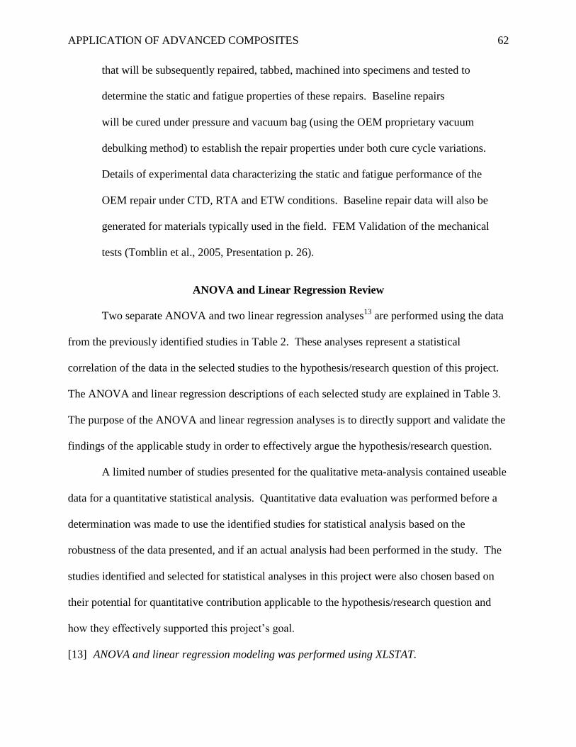
APPLICATION OF ADVANCED COMPOSITES 62
that will be subsequently repaired, tabbed, machined into specimens and tested to
determine the static and fatigue properties of these repairs. Baseline repairs
will be cured under pressure and vacuum bag (using the OEM proprietary vacuum
debulking method) to establish the repair properties under both cure cycle variations.
Details of experimental data characterizing the static and fatigue performance of the
OEM repair under CTD, RTA and ETW conditions. Baseline repair data will also be
generated for materials typically used in the field. FEM Validation of the mechanical
tests (Tomblin et al., 2005, Presentation p. 26).
ANOVA and Linear Regression Review
Two separate ANOVA and two linear regression analyses13
are performed using the data
from the previously identified studies in Table 2. These analyses represent a statistical
correlation of the data in the selected studies to the hypothesis/research question of this project.
The ANOVA and linear regression descriptions of each selected study are explained in Table 3.
The purpose of the ANOVA and linear regression analyses is to directly support and validate the
findings of the applicable study in order to effectively argue the hypothesis/research question.
A limited number of studies presented for the qualitative meta-analysis contained useable
data for a quantitative statistical analysis. Quantitative data evaluation was performed before a
determination was made to use the identified studies for statistical analysis based on the
robustness of the data presented, and if an actual analysis had been performed in the study. The
studies identified and selected for statistical analyses in this project were also chosen based on
their potential for quantitative contribution applicable to the hypothesis/research question and
how they effectively supported this project’s goal.
[13] ANOVA and linear regression modeling was performed using XLSTAT.
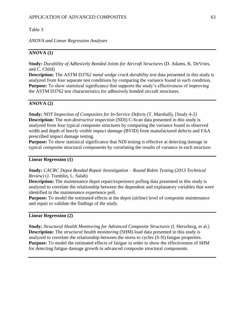
APPLICATION OF ADVANCED COMPOSITES 63
Table 3
ANOVA and Linear Regression Analyses
ANOVA (1)
Study: Durability of Adhesively Bonded Joints for Aircraft Structures (D. Adams, K. DeVries,
and C. Child)
Description: The ASTM D3762 metal wedge crack durability test data presented in this study is
analyzed from four separate test conditions by comparing the variance found in each condition.
Purpose: To show statistical significance that supports the study’s effectiveness of improving
the ASTM D3762 test characteristics for adhesively bonded aircraft structures.
ANOVA (2)
Study: NDT Inspection of Composites for In-Service Defects (T. Marshall), [Study 4-2]
Description: The non-destructive inspection (NDI) C-Scan data presented in this study is
analyzed from four typical composite structures by comparing the variance found in observed
width and depth of barely visible impact damage (BVID) from manufactured defects and FAA
prescribed impact damage testing.
Purpose: To show statistical significance that NDI testing is effective at detecting damage in
typical composite structural components by correlating the results of variance in each structure.
Linear Regression (1)
Study: CACRC Depot Bonded Repair Investigation – Round Robin Testing (2013 Technical
Review) (J. Tomblin, L. Salah)
Description: The maintenance depot repair/experience polling data presented in this study is
analyzed to correlate the relationship between the dependent and explanatory variables that were
identified in the maintenance experience poll.
Purpose: To model the estimated effects at the depot (airline) level of composite maintenance
and repair to validate the findings of the study.
Linear Regression (2)
Study: Structural Health Monitoring for Advanced Composite Structures (I. Herszberg, et al.)
Description: The structural health monitoring (SHM) load data presented in this study is
analyzed to correlate the relationship between the stress to cycles (S-N) fatigue properties.
Purpose: To model the estimated effects of fatigue in order to show the effectiveness of SHM
for detecting fatigue damage growth in advanced composite structural components.
APPLICATION OF ADVANCED COMPOSITES 64
Results
Meta-Analysis
Validation Testing (VT) Studies
VT Study (1).
Damage Tolerance Testing and Analysis Protocols for Full-Scale Composite Airframe Structures
Under Repeated Loading (J. Tomblin, W. Seneviratne)
This study exceeds the categorical evaluative criteria by identifying the methodology and
approaches necessary for comprehensive process improvements of full-scale validation testing
by determining fatigue life with respect to damage tolerance (life and load factors), evaluating
impact threats with respect to load-life capability, and the incorporation of design changes
without the addition of extra testing (Tomblin & Seneviratne, 2008). This is a methodology-
based study that lays the groundwork for achieving best practice methods and procedures for
full-scale testing of composite airframe structures (Tomblin & Seneviratne, 2008). The
following benefits and advantages to aviation were identified:
Incorporation of damage into scatter analysis. Load-Life-Damage: investigate large VID
damage, further studies. Load-Life Shift: investigate different categories of
damages/repairs in the same full-scale test article damage, design changes, i.e. gross
weight increase, LEF during certification vs. improved LEF and reliability of designed
life (Tomblin & Seneviratne, 2008, Presentation p. 29).
The future needs and direction were identified in the findings of the study14
that points out the
need for “reliable NDI and health monitoring techniques for damage characterization during full-
scale testing and service” which should be noted that this correlates to the findings in other
studies and validates the hypothesis/research question of this project.
[14] The findings of this study can be found on p. 43 of this paper.
APPLICATION OF ADVANCED COMPOSITES 65
VT Study (2).
Durability of Adhesively Bonded Joints for Aircraft Structures (D. Adams, K. DeVries, and C.
Child)
This study meets the categorical evaluative criteria by identifying improvements for the
ASTM D3762 metal wedge crack durability test characteristics for use with adhesively bonded
composite joints which validates the need to improve this test for composite applications. This
study is ongoing with future research required before new ASTM D3762 can be implemented.
The methodologies for implementation and benefits to aviation have been identified as follows:
As this research project progresses, test results and proposed additions and revisions to
the ASTM D3762 standard will continue to be communicated regularly to ASTM
Committee D14 on adhesives. In addition to proposing revisions to this standardized test
method, research results from this investigation will be disseminated through an FAA
technical report and journal publications. Expected benefits to aviation include an
improved adhesive bond durability test method for use in assessing the reliability of
adhesively bonded aircraft structures (Adams et al., 2011, p. 20).
The test data from this study is analyzed in the next section of this paper to validate the results
and findings in order to show that the test was effective.
VT Study (3).
Damage Tolerance Test Method Development for Sandwich Composites (D. Adams, B.
Kuramoto)
This study meets the categorical evaluative criteria by identifying needed standardized
damage tolerance test methods for sandwich composites. The proposed methodology of this
study focused on the “high level of maturity” of existing damage tolerance and damage
resistance standards in-place for monolithic composite structures (Adams & Kuramoto, 2012,
APPLICATION OF ADVANCED COMPOSITES 66
Presentation p. 4). This study’s primary objective was to develop a standardized ASTM test
method for structural sandwich composite components that (at present) does not exist. When
this research is complete, its potential for implementation is high due to the immediate industry
standard need of this test method which validates this study’s effectiveness. The benefits and
advantages to aviation have been identified as follows:
Expected benefits to aviation from this research project include the development of
standardized test methodologies for use in assessing the damage tolerance of sandwich
composites used in aircraft structures. Other benefits include test results used to predict
damage tolerance of sandwich composites, and research results on scaling of results
towards composite sandwich structures (Adams & Kuramoto, 2012, p. 12), (Adams &
Kuramoto, 2012, Presentation p. 23).
VT Study (4-1).
In-service Inspection Guidelines for Composite Aerospace Structures (J. Heida, D. Platenkamp)
This study meets the categorical evaluative criteria (with limitations) by identifying and
evaluating in-service non-destructive inspection (NDI) testing methods and techniques used in
the aerospace industry. Through this study’s evaluation of in-service NDI methods and
techniques, guidelines are proposed for their use of detecting damage in composite structures.
The limiting factor of this study is that while it is highly informative as a guideline for use, it
does not propose any new methods or techniques for NDI. However, due to the relevance of
NDI as pointed out in other studies, this study’s effectiveness for implementation as a
standardized authoritative guide to aerospace NDI methods and techniques is suggested and can
be adopted as such. The testing performed in this study was adapted from study 4-2 (below) and
will be analyzed using the data from study 4-2 to show the effectiveness of NDI testing.
APPLICATION OF ADVANCED COMPOSITES 67
VT Study (4-2).
NDT Inspection of Composites for In-Service Defects (T. Marshall)
This study is used for quantitative analysis only and will be discussed in the next section.
The summary and findings of this study can be found on p. 48-49 of this paper.
VT Study (5).
Boeing Composite Airframe Damage Tolerance and Service Experience (A. Fawcett, G. Oakes)
This study meets the categorical evaluative criteria (with limitations) by identifying and
providing industry examples of design criteria for damage tolerant carbon fiber reinforced
polymer (CFRP) primary aircraft structures used for commercial transport aircraft, and how the
manufacturer (Boeing) has enabled its maintainability (Fawcett & Oakes, n.d.). The limiting
factor of this study is that while it is highly informative and effective for the dissemination of in-
service impact damage experience, it does not suggest or propose new methodologies for damage
tolerance or damage detection. However, this study does contribute to industry collaboration for
the promulgation of robust design criterion and standards for maintainable structures. It is also
noted that this study found that Boeing’s current non-destructive testing (NDT)15
methods and
techniques for detecting damage on in-service structures (737 and 777) have been validated and
are effective. This study points out that current in-service use of non-destructive inspection
(NDI) is effective for the detection of composite damage and component failure.
[15] The term NDT is synonymous with non-destructive inspection (NDI).
VT Study (6).
Impact Damage Formation on Composite Aircraft Structures (H. Kim)
This study meets the categorical evaluative criteria by identifying and evaluating the
impact damage vulnerability of aircraft composite structures specific to wide-area contact from
APPLICATION OF ADVANCED COMPOSITES 68
ground support equipment (GSE), high-velocity hail/ice, and large radius metal tips. This study
critically examines and investigates non-visible impact damage (NVID) on structural composite
components in order to fully assess NVID caused by an impact event. The testing methodologies
used in this study included finite element analysis (FEA) modeling of impact events that
produced accurate damage simulation for analysis of typical aircraft composite structures that
provides the industry with a better understanding of blunt-force impact damage (Kim, 2012).
This study validates the need for impact damage testing due to the typical occurrence of sub-
surface damage after an impact event without any visible surface indications. The benefits and
advantages to aviation regarding wide-area blunt impact are as follows:
GSE wide-area blunt impact: understanding of prospective damage produced from wide-
area GSE impact events. Awareness of phenomena and possible internal failure modes
for damage tolerance considerations. Provides key information on mode and extent of
seeded damage, particularly non-visible impact damage (NVID) from blunt impact
threats. Threat conditions causing significant damage – range of energy level needed.
Establish FEA models that provide the capability to predict: full detailed failure process –
large deformations, failure initiation, growth, key failure modes. Visibility of the damage
produced – failure criteria for impact damage visibility. Small scale onset of cracks and
delamination leading to greater damage and degradation of structural integrity. Establish
methodologies to analyze whole composite aircraft vs. substructures: GSE impacts
inducing whole-aircraft motion. Surrounding GSE secondary impact: identify how to
detect/monitor occurrence of damaging events. What inspection technique should be
used and where, e.g., video cameras and sensors that can help to determine impact energy
(Kim, 2012, Presentation p. 12).
APPLICATION OF ADVANCED COMPOSITES 69
VT Study (7).
Structural Health Monitoring for Advanced Composite Structures (Herszberg, et al.)
This study is used for quantitative analysis only in-conjunction with the fatigue data from
FAA AR-03/46 and will be discussed in the next section. The summary and findings of this
study can be found on p. 51-52 of this paper.
Certification Standards (CS) Studies
CS Study (1).
Status of FAA’s Actions to Oversee the Safety of Composite Airplanes (Government
Accountability Office)
This report exceeds the categorical evaluative criteria by providing oversight for the
certification of composite Part 25 aircraft. The report was conducted by the GAO to address the
safety concerns associated with the increasing use of composites for commercial aircraft
construction; specifically for primary structural applications such as wings and fuselage
components. This report is directed towards the certification process of Boeing’s 787
Dreamliner due to the 787 being the first large commercial transport aircraft constructed mostly
with advanced composites (GAO, 2011). The GAO’s methodology for conducting this report
was extensive and is described as follows:
This report addresses the Federal Aviation Administration’s (FAA) and the European
Aviation Safety Agency’s (EASA) certification of airplanes using composite materials,
specifically the agencies’ processes for developing special requirements to ensure that
Boeing demonstrates the 787 composite fuselage and wings meet current safety levels,
and FAA’s actions to address safety-related concerns associated with repairing and
maintaining composite airplanes identified by literature and stakeholders. We focused on
FAA’s and EASA’s actions as they relate to the certification of the Boeing 787 because it
APPLICATION OF ADVANCED COMPOSITES 70
is the first large transport category airplane for commercial use with a composite airframe
structure to undergo the certification process. To address these objectives, we reviewed
FAA and EASA regulations, policies, and processes and Boeing certification documents
for the special conditions and review items the agencies indicated were related to the
787’s composite fuselage and wings. We conducted a literature search and reviewed 39
journal articles and technical papers related to the repair and maintenance of composite
airplanes. We interviewed 11 stakeholders with expertise in the area of maintenance and
repair of composite materials in airplanes and representing a variety of perspectives,
including manufacturers, repair stations, academic researchers, and air carriers (GAO,
2011, Appendix I p. 40).
The methodologies and objectives also included the “review of FAA’s process to develop special
conditions for the 787 composite structures, EASA certification review process, and the
identification of repair and maintenance concerns.” (GAO, 2011, Appendix I p. 40-42).
The purpose and objectives of this report were warranted based on valid certification and
safety concerns for this type of aircraft. The repair and maintenance concerns found by the GAO
were also revealed in the supporting research performed by the Commercial Aircraft Composite
Repair Committee (CACRC) and can be directly correlated. Although this report found that the
FAA “followed its certification process in assessing the Boeing 787 airplane's composite
fuselage and wings against applicable FAA airworthiness standards.” (GAO, 2011, What GAO
Found) However, due to the lack of applicable certification standards, the FAA “applied five
special conditions when it found that its airworthiness standards were not adequate to ensure that
the composite structures would comply with existing safety levels.” (GAO, 2011, What GAO
Found)
APPLICATION OF ADVANCED COMPOSITES 71
CS Study (2).
FAA Composite Safety and Certification Initiatives (L. Ilcewicz)
This study exceeds the categorical evaluative criteria by identifying and evaluating the
FAA’s methodologies used to address current industry concerns specific to safety and
certification initiatives. The primary objectives for this study were to “work with industry, other
government agencies, and academia to ensure safe and efficient deployment of composite
technologies used in existing and future aircraft, and to update policies, advisory circulars,
training, and detailed background used to support standardized composite practices.” (Ilcewicz,
2010, Presentation p. 4). The goal to promote industry standardization is an important aspect of
this study that validates the need for new composite aircraft certification standards. The
summary of action stated in this study from 2006 to 2009 is as follows:
Critical safety data shared in unique forum of practitioners – captured in web files, new
CMH-17 content and FAA course. Five categories of damage were proposed for damage
tolerance and maintenance consideration. Integrated efforts in structural substantiation,
maintenance and operations interface help ensure complete coverage for safety.
Coordinated inspection, engineering disposition and repair is needed for safe
maintenance. Reporting by operations is essential for detection of critical damage from
anomalous events. FAA is committed to CS&CI with industry, academia and
government groups (~380 participants in three workshops). Damage tolerance and
maintenance initiatives are active. Principles of safety management will continue to be
used in future developments (policy, guidance and training) (Ilcewicz, 2010, Presentation
p. 16).
APPLICATION OF ADVANCED COMPOSITES 72
CS Study (3).
Simplifying Certification of Discontinuous Composite Material Forms for Primary Aircraft
Structures (M. Tuttle, et al.)
This study meets the categorical evaluative criteria by identifying and evaluating the
certification methodology required for discontinuous fiber composite (DFC) parts that are
“produced using compression molding and are being implemented in complex structural
geometries in new generation commercial aircraft.” (Tuttle et al., 2013, Abstract) Although DFC
parts are not as common as traditional monolithic or sandwich components (at present), their use
will undoubtedly increase for future applications based on their unique characteristics and design
potential. Increase of DFC material use will mandate the requirement for adequate certification
guidelines. This study reveals some initial data and results regarding the physical behavior of
DFC material. While this study does not form conclusive certification guidelines for DFC
material, it does (proactively) research and test the material behavior in order to begin a
comprehensive approach for future certification guidance. The following is a summary of action
for this study:
A multi-year study with an ultimate goal of simplifying certification of Discontinuous
Fiber Composite (DFC) parts has been undertaken by members of AMTAS (Advanced
Materials for Transport Aircraft Structures), which is one of two university groups that
together form the Joint Advanced Materials & Structures (JAMS) Center of Excellence.
HexMC®, a DFC system produced by the Hexcel Corporation, is being used as a model
material. The multi-year study will involve tests and analyses at both the coupon level
and at the component level (Tuttle et al., 2013, Summary).
APPLICATION OF ADVANCED COMPOSITES 73
The benefits and advantages to aviation are as follows:
FAA: Program objective supports safety regulations for design, production, and
airworthiness certification of DFC parts. Industry: Program will contribute towards
broader use of DFC structures at lower cost and lower weight. Academia: Represents an
applied research project addressing an immediate need in industry and providing
pertinent research & educational training for new aerospace engineers (Tuttle et al., 2013,
Presentation p. 22).
Maintenance and Repair (M&R) Studies
M&R Study (1).
CACRC Depot Bonded Repair Investigation – Round Robin Testing (2013 Technical Review)
(J. Tomblin, L. Salah)
This study exceeds the categorical evaluative criteria by investigating and evaluating
current depot (airline) level composite bonded repair. This was accomplished by comparing
current industry standardized repair procedures (CACRC) with actual depot level repairs to
analyze the variances based on technician experience and training. Material standardization and
acquisition at the depot level was also investigated as well as a comparison of repair strength
between CACRC field repairs with the same type of original equipment manufacturer (OEM)
repair. This study’s investigative and evaluative methodology proved to be effective at revealing
process deficiencies with depot level repairs that included a lack of composite repair training
programs, and a lack of inspection required for critical steps of the repair (Tomblin & Salah,
2013). This study validates the need for composite maintenance and repair standardization
throughout the industry (at every repair level), and clearly identifies that composite repair
standardization (currently) is a safety concern which was also identified in the GAO report
APPLICATION OF ADVANCED COMPOSITES 74
previously evaluated. The maintenance technician polling data from this study is used for a
linear regression in the next section of this paper to validate the study’s findings and show the
correlation between technician experience/maintenance actions performed vs. the amount of
rework. This study concluded with the following benefits and advantages to aviation:
Evaluate the completeness and adequacy of the existing CACRC standards (identify areas
of improvement). Objective: robust/validated CACRC repair procedures/techniques
standardized across different OEMs, airlines and repair stations. Provide
recommendations pertaining to repair training, materials and standards to improve
structural integrity of repaired composite components (robust infrastructure for
maintenance and supportability). Need for composite repair technician training and
certification, and periodic certification validation. Provide a measure of the structural
integrity (static strength and residual strength after fatigue) of field repairs as compared
to the OEM baseline repairs (Tomblin & Salah, 2013, Presentation p. 24).
M&R Study (2).
CACRC Depot Bonded Repair Investigation – Round Robin Testing (2012 Technical Review)
(J. Tomblin, L. Salah)
This study meets the categorical evaluative criteria by establishing and evaluating
standardized (CACRC) composite repair methods and procedures that are used for the
comparative standard in the 2013 continuation study previously evaluated. This study’s
methodology focuses on initial research and investigation of bonded repairs by establishing the
program objectives that “evaluate the static strength and residual strength after fatigue of OEM
vs. field bonded repairs applied to composite sandwich structures, performed at different
operator depots, and evaluate the static strength and residual strength after fatigue of OEM vs.
APPLICATION OF ADVANCED COMPOSITES 75
field bonded repairs subjected to impact damage and defective process parameters.” (Tomblin &
Salah, 2012, Presentation p. 8). This study concluded with the following benefits and advantages
to aviation:
To investigate the effectiveness of “OEM environment” vs. field repairs and the
variability due to repair implementation at various operator depots. To understand the
environmental durability and the residual strength after fatigue of bonded repairs
subjected to various processes and environments. To identify key elements in the
implementation of bonded repairs that ensures repeatability and structural integrity of
these repairs. To provide recommendations pertaining to repair technician training and
repair process control (Tomblin & Salah, 2012, Presentation p. 25).
M&R Study (3-1).
Effect of Repair Procedures Applied to Composite Airframe Structures (J. Tomblin, L. Salah,
and C. Yang), Laminate and sandwich structures.
This study meets the categorical evaluative criteria by identifying and assessing the
variable effects on the repair strength of laminate and sandwich structures, evaluating the
“strength and durability of poorly bonded repairs that passed NDI”, and “validating existing
CACRC standards” (Tomblin et al., 2006, Presentation p. 3). Further objectives also included
“providing recommendations pertaining to proper repair process implementation” and
“developing an analysis method and corresponding failure criteria for structural sizing of bonded
repairs” (Tomblin et al., 2006, Presentation p. 3). The research methodology was task-oriented
which effectively “generated baseline repair data for various laminate and sandwich materials”
(Tomblin et al., 2006, Presentation p. 26).
APPLICATION OF ADVANCED COMPOSITES 76
The benefits and advantages to aviation are as follows:
To assess the effects of surface contamination and process variations on the performance
of bonded repairs. To develop rigorous repeatable repair processes that ensure structural
integrity of bonded repairs. To gain confidence in bonded structural repairs. To provide
guidance for analytical modeling of repairs (Tomblin et al., 2006, Presentation p. 27).
M&R Study (3-2).
Effect of Repair Procedures Applied to Composite Airframe Structures (J. Tomblin, L. Salah,
and C. Yang), Laminate scarf joints.
This study meets the categorical evaluative criteria by identifying and assessing the
variable effects “on the performance of repairs applied to solid laminates representative of 787
structure configurations” specific to laminate scarf joints (Tomblin et al., 2005, Presentation p.
3). The research methodology for this study was the same as M&R Study 3-1 (task-oriented)
with the difference in tested structures (laminate scarf joints) for this study. This study was also
effective at generating baseline repair data after the completion of each task, and concluded with
the same benefits and advantages to aviation as M&R Study 3-1.
Both of these studies (3-1 and 3-2) validate the need for assessing the repair effects on
these structures in order to identify a best practice repair method/technique applicable to each
structure that yields the highest strength and longevity. This can be directly correlated to repair
standardization and process improvement with respect to the category of composite maintenance
and repair.
Note. This concludes the meta-analysis results for composite materials studies, categorical
results are given in the summary section of this project.
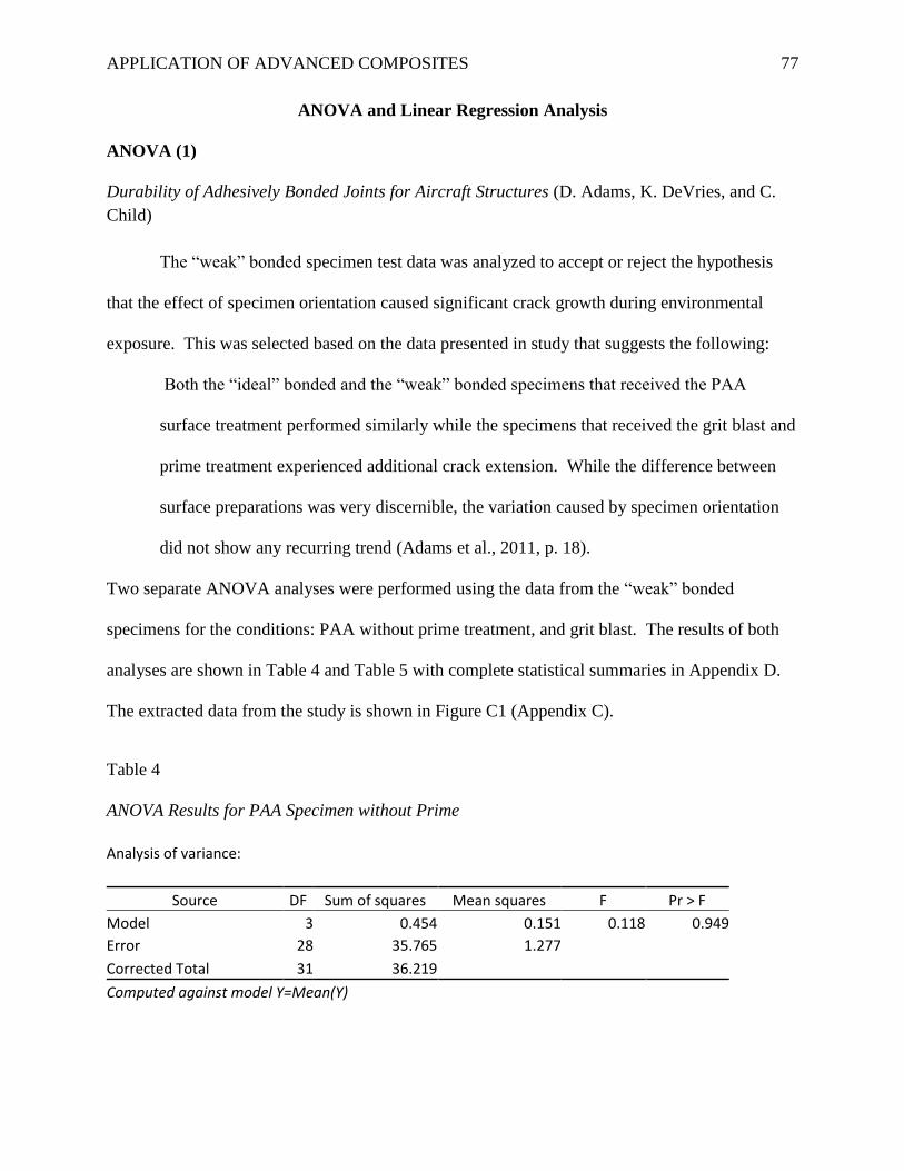
APPLICATION OF ADVANCED COMPOSITES 77
ANOVA and Linear Regression Analysis
ANOVA (1)
Durability of Adhesively Bonded Joints for Aircraft Structures (D. Adams, K. DeVries, and C.
Child)
The “weak” bonded specimen test data was analyzed to accept or reject the hypothesis
that the effect of specimen orientation caused significant crack growth during environmental
exposure. This was selected based on the data presented in study that suggests the following:
Both the “ideal” bonded and the “weak” bonded specimens that received the PAA
surface treatment performed similarly while the specimens that received the grit blast and
prime treatment experienced additional crack extension. While the difference between
surface preparations was very discernible, the variation caused by specimen orientation
did not show any recurring trend (Adams et al., 2011, p. 18).
Two separate ANOVA analyses were performed using the data from the “weak” bonded
specimens for the conditions: PAA without prime treatment, and grit blast. The results of both
analyses are shown in Table 4 and Table 5 with complete statistical summaries in Appendix D.
The extracted data from the study is shown in Figure C1 (Appendix C).
Table 4
ANOVA Results for PAA Specimen without Prime
Analysis of variance:
Source DF Sum of squares Mean squares F Pr > F
Model 3 0.454 0.151 0.118 0.949
Error 28 35.765 1.277 Corrected Total 31 36.219
Computed against model Y=Mean(Y)
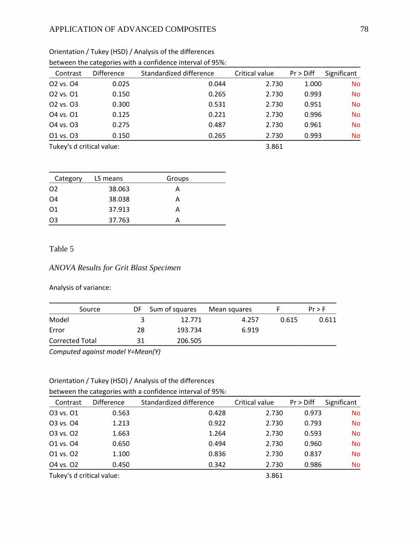
APPLICATION OF ADVANCED COMPOSITES 78
Orientation / Tukey (HSD) / Analysis of the differences between the categories with a confidence interval of 95%:
Contrast Difference Standardized difference Critical value Pr > Diff Significant
O2 vs. O4 0.025 0.044 2.730 1.000 No
O2 vs. O1 0.150 0.265 2.730 0.993 No
O2 vs. O3 0.300 0.531 2.730 0.951 No
O4 vs. O1 0.125 0.221 2.730 0.996 No
O4 vs. O3 0.275 0.487 2.730 0.961 No
O1 vs. O3 0.150 0.265 2.730 0.993 No
Tukey's d critical value:
3.861
Category LS means Groups O2 38.063 A O4 38.038 A O1 37.913 A O3 37.763 A
Table 5
ANOVA Results for Grit Blast Specimen
Analysis of variance:
Source DF Sum of squares Mean squares F Pr > F
Model 3 12.771 4.257 0.615 0.611
Error 28 193.734 6.919 Corrected Total 31 206.505
Computed against model Y=Mean(Y)
Orientation / Tukey (HSD) / Analysis of the differences between the categories with a confidence interval of 95%:
Contrast Difference Standardized difference Critical value Pr > Diff Significant
O3 vs. O1 0.563 0.428 2.730 0.973 No
O3 vs. O4 1.213 0.922 2.730 0.793 No
O3 vs. O2 1.663 1.264 2.730 0.593 No
O1 vs. O4 0.650 0.494 2.730 0.960 No
O1 vs. O2 1.100 0.836 2.730 0.837 No
O4 vs. O2 0.450 0.342 2.730 0.986 No
Tukey's d critical value:
3.861
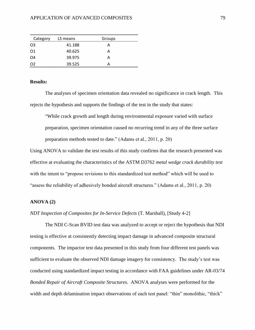
APPLICATION OF ADVANCED COMPOSITES 79
Category LS means Groups O3 41.188 A O1 40.625 A O4 39.975 A O2 39.525 A
Results:
The analyses of specimen orientation data revealed no significance in crack length. This
rejects the hypothesis and supports the findings of the test in the study that states:
“While crack growth and length during environmental exposure varied with surface
preparation, specimen orientation caused no recurring trend in any of the three surface
preparation methods tested to date.” (Adams et al., 2011, p. 20)
Using ANOVA to validate the test results of this study confirms that the research presented was
effective at evaluating the characteristics of the ASTM D3762 metal wedge crack durability test
with the intent to “propose revisions to this standardized test method” which will be used to
“assess the reliability of adhesively bonded aircraft structures.” (Adams et al., 2011, p. 20)
ANOVA (2)
NDT Inspection of Composites for In-Service Defects (T. Marshall), [Study 4-2]
The NDI C-Scan BVID test data was analyzed to accept or reject the hypothesis that NDI
testing is effective at consistently detecting impact damage in advanced composite structural
components. The impactor test data presented in this study from four different test panels was
sufficient to evaluate the observed NDI damage imagery for consistency. The study’s test was
conducted using standardized impact testing in accordance with FAA guidelines under AR-03/74
Bonded Repair of Aircraft Composite Structures. ANOVA analyses were performed for the
width and depth delamination impact observations of each test panel: “thin” monolithic, “thick”
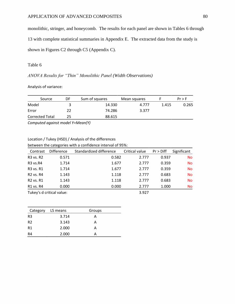
APPLICATION OF ADVANCED COMPOSITES 80
monolithic, stringer, and honeycomb. The results for each panel are shown in Tables 6 through
13 with complete statistical summaries in Appendix E. The extracted data from the study is
shown in Figures C2 through C5 (Appendix C).
Table 6
ANOVA Results for “Thin” Monolithic Panel (Width Observations)
Analysis of variance:
Source DF Sum of squares Mean squares F Pr > F
Model 3 14.330 4.777 1.415 0.265
Error 22 74.286 3.377 Corrected Total 25 88.615
Computed against model Y=Mean(Y)
Location / Tukey (HSD) / Analysis of the differences between the categories with a confidence interval of 95%: Contrast Difference Standardized difference Critical value Pr > Diff Significant
R3 vs. R2 0.571 0.582 2.777 0.937 No
R3 vs.R4 1.714 1.677 2.777 0.359 No
R3 vs. R1 1.714 1.677 2.777 0.359 No
R2 vs. R4 1.143 1.118 2.777 0.683 No
R2 vs. R1 1.143 1.118 2.777 0.683 No
R1 vs. R4 0.000 0.000 2.777 1.000 No
Tukey's d critical value:
3.927
Category LS means Groups R3 3.714 A R2 3.143 A R1 2.000 A R4 2.000 A
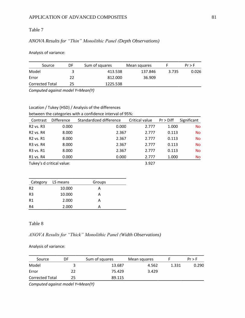
APPLICATION OF ADVANCED COMPOSITES 81
Table 7
ANOVA Results for “Thin” Monolithic Panel (Depth Observations)
Analysis of variance:
Source DF Sum of squares Mean squares F Pr > F
Model 3 413.538 137.846 3.735 0.026
Error 22 812.000 36.909 Corrected Total 25 1225.538
Computed against model Y=Mean(Y)
Location / Tukey (HSD) / Analysis of the differences between the categories with a confidence interval of 95%: Contrast Difference Standardized difference Critical value Pr > Diff Significant
R2 vs. R3 0.000 0.000 2.777 1.000 No
R2 vs. R4 8.000 2.367 2.777 0.113 No
R2 vs. R1 8.000 2.367 2.777 0.113 No
R3 vs. R4 8.000 2.367 2.777 0.113 No
R3 vs. R1 8.000 2.367 2.777 0.113 No
R1 vs. R4 0.000 0.000 2.777 1.000 No
Tukey's d critical value:
3.927
Category LS means Groups R2 10.000 A R3 10.000 A R1 2.000 A R4 2.000 A
Table 8
ANOVA Results for “Thick” Monolithic Panel (Width Observations)
Analysis of variance:
Source DF Sum of squares Mean squares F Pr > F
Model 3 13.687 4.562 1.331 0.290
Error 22 75.429 3.429 Corrected Total 25 89.115
Computed against model Y=Mean(Y)
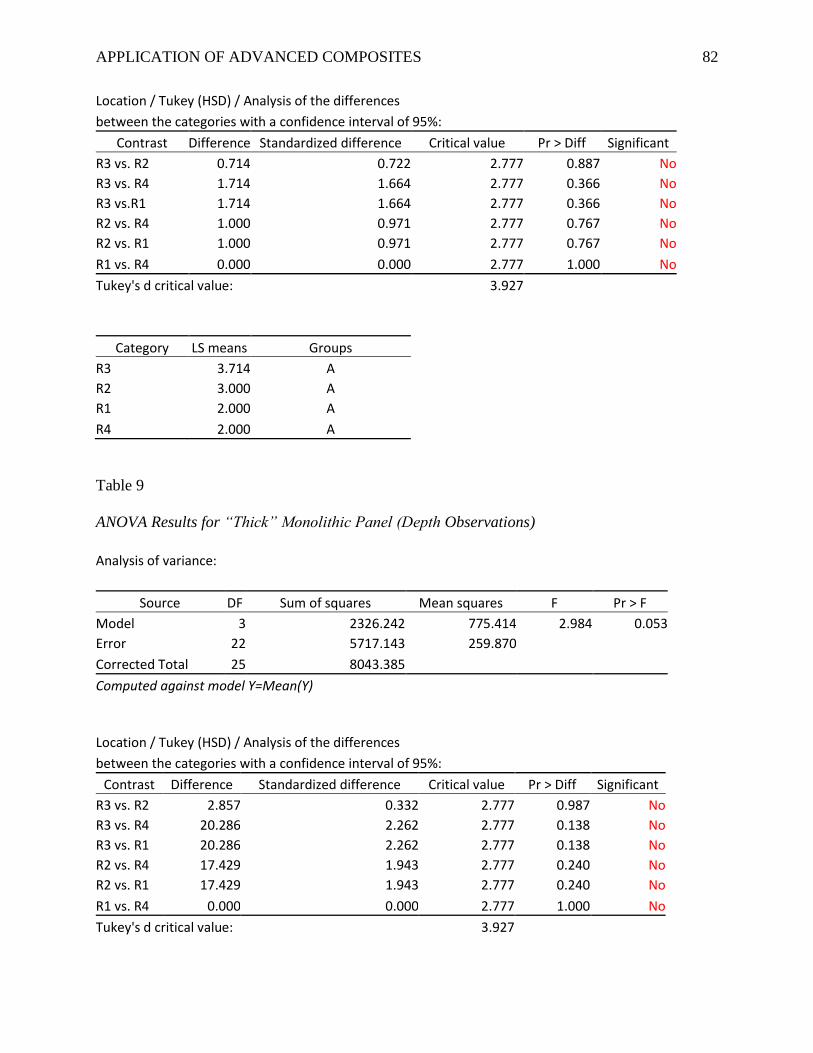
APPLICATION OF ADVANCED COMPOSITES 82
Location / Tukey (HSD) / Analysis of the differences between the categories with a confidence interval of 95%: Contrast Difference Standardized difference Critical value Pr > Diff Significant
R3 vs. R2 0.714 0.722 2.777 0.887 No
R3 vs. R4 1.714 1.664 2.777 0.366 No
R3 vs.R1 1.714 1.664 2.777 0.366 No
R2 vs. R4 1.000 0.971 2.777 0.767 No
R2 vs. R1 1.000 0.971 2.777 0.767 No
R1 vs. R4 0.000 0.000 2.777 1.000 No
Tukey's d critical value:
3.927
Category LS means Groups R3 3.714 A R2 3.000 A R1 2.000 A R4 2.000 A
Table 9
ANOVA Results for “Thick” Monolithic Panel (Depth Observations)
Analysis of variance:
Source DF Sum of squares Mean squares F Pr > F
Model 3 2326.242 775.414 2.984 0.053
Error 22 5717.143 259.870 Corrected Total 25 8043.385
Computed against model Y=Mean(Y)
Location / Tukey (HSD) / Analysis of the differences between the categories with a confidence interval of 95%: Contrast Difference Standardized difference Critical value Pr > Diff Significant
R3 vs. R2 2.857 0.332 2.777 0.987 No
R3 vs. R4 20.286 2.262 2.777 0.138 No
R3 vs. R1 20.286 2.262 2.777 0.138 No
R2 vs. R4 17.429 1.943 2.777 0.240 No
R2 vs. R1 17.429 1.943 2.777 0.240 No
R1 vs. R4 0.000 0.000 2.777 1.000 No
Tukey's d critical value:
3.927
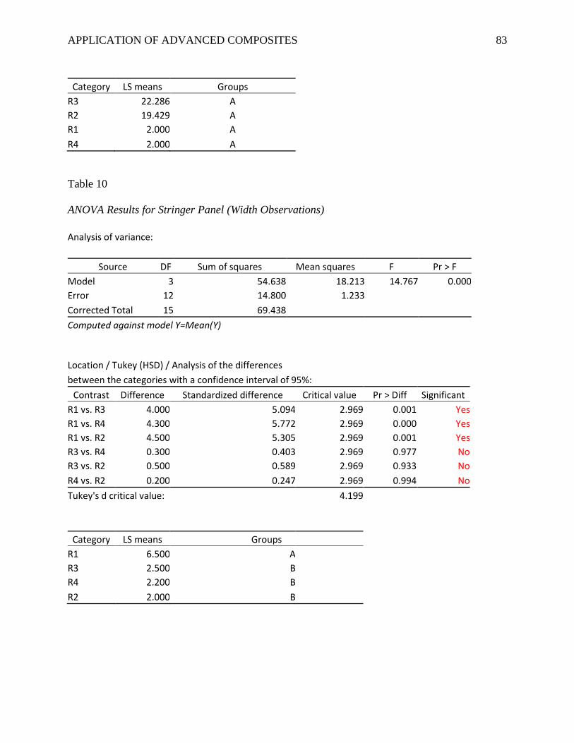
APPLICATION OF ADVANCED COMPOSITES 83
Category LS means Groups R3 22.286 A R2 19.429 A R1 2.000 A R4 2.000 A
Table 10
ANOVA Results for Stringer Panel (Width Observations)
Analysis of variance:
Source DF Sum of squares Mean squares F Pr > F
Model 3 54.638 18.213 14.767 0.000
Error 12 14.800 1.233 Corrected Total 15 69.438
Computed against model Y=Mean(Y)
Location / Tukey (HSD) / Analysis of the differences between the categories with a confidence interval of 95%: Contrast Difference Standardized difference Critical value Pr > Diff Significant
R1 vs. R3 4.000 5.094 2.969 0.001 Yes
R1 vs. R4 4.300 5.772 2.969 0.000 Yes
R1 vs. R2 4.500 5.305 2.969 0.001 Yes
R3 vs. R4 0.300 0.403 2.969 0.977 No
R3 vs. R2 0.500 0.589 2.969 0.933 No
R4 vs. R2 0.200 0.247 2.969 0.994 No
Tukey's d critical value:
4.199
Category LS means Groups R1 6.500 A R3 2.500 B
R4 2.200 B R2 2.000 B
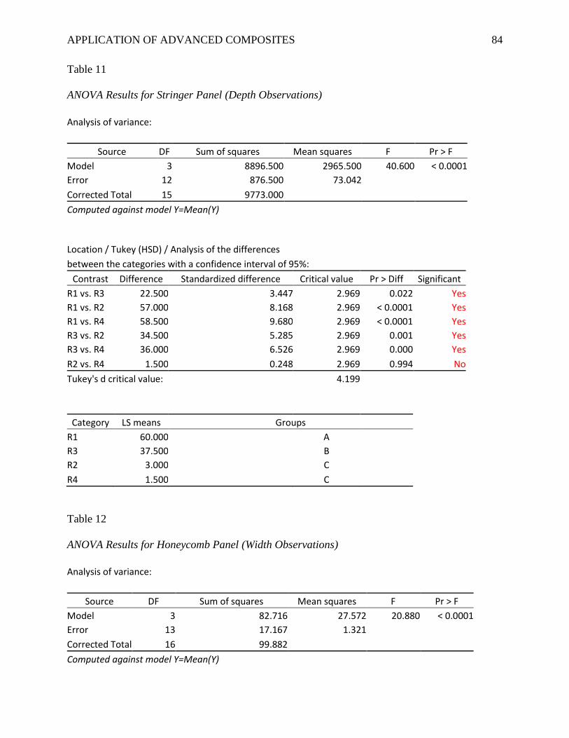
APPLICATION OF ADVANCED COMPOSITES 84
Table 11
ANOVA Results for Stringer Panel (Depth Observations)
Analysis of variance:
Source DF Sum of squares Mean squares F Pr > F
Model 3 8896.500 2965.500 40.600 < 0.0001
Error 12 876.500 73.042 Corrected Total 15 9773.000
Computed against model Y=Mean(Y)
Location / Tukey (HSD) / Analysis of the differences between the categories with a confidence interval of 95%: Contrast Difference Standardized difference Critical value Pr > Diff Significant
R1 vs. R3 22.500 3.447 2.969 0.022 Yes R1 vs. R2 57.000 8.168 2.969 < 0.0001 Yes R1 vs. R4 58.500 9.680 2.969 < 0.0001 Yes R3 vs. R2 34.500 5.285 2.969 0.001 Yes R3 vs. R4 36.000 6.526 2.969 0.000 Yes R2 vs. R4 1.500 0.248 2.969 0.994 No Tukey's d critical value:
4.199
Category LS means Groups R1 60.000
A
R3 37.500
B R2 3.000
C
R4 1.500 C
Table 12
ANOVA Results for Honeycomb Panel (Width Observations)
Analysis of variance:
Source DF Sum of squares Mean squares F Pr > F
Model 3 82.716 27.572 20.880 < 0.0001
Error 13 17.167 1.321 Corrected Total 16 99.882
Computed against model Y=Mean(Y)
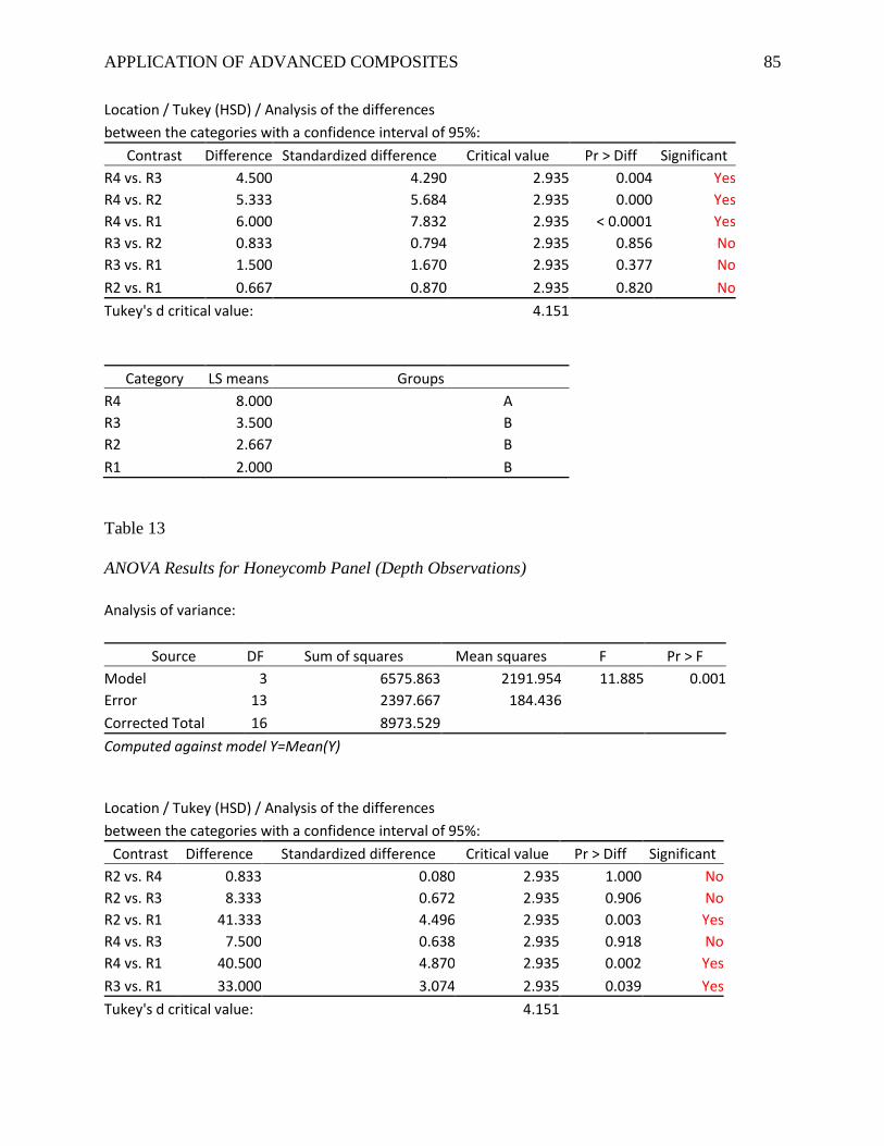
APPLICATION OF ADVANCED COMPOSITES 85
Location / Tukey (HSD) / Analysis of the differences between the categories with a confidence interval of 95%: Contrast Difference Standardized difference Critical value Pr > Diff Significant
R4 vs. R3 4.500 4.290 2.935 0.004 Yes
R4 vs. R2 5.333 5.684 2.935 0.000 Yes
R4 vs. R1 6.000 7.832 2.935 < 0.0001 Yes
R3 vs. R2 0.833 0.794 2.935 0.856 No
R3 vs. R1 1.500 1.670 2.935 0.377 No
R2 vs. R1 0.667 0.870 2.935 0.820 No
Tukey's d critical value:
4.151
Category LS means Groups R4 8.000 A R3 3.500
B
R2 2.667
B R1 2.000 B
Table 13
ANOVA Results for Honeycomb Panel (Depth Observations)
Analysis of variance:
Source DF Sum of squares Mean squares F Pr > F
Model 3 6575.863 2191.954 11.885 0.001
Error 13 2397.667 184.436 Corrected Total 16 8973.529
Computed against model Y=Mean(Y)
Location / Tukey (HSD) / Analysis of the differences between the categories with a confidence interval of 95%: Contrast Difference Standardized difference Critical value Pr > Diff Significant
R2 vs. R4 0.833 0.080 2.935 1.000 No
R2 vs. R3 8.333 0.672 2.935 0.906 No
R2 vs. R1 41.333 4.496 2.935 0.003 Yes
R4 vs. R3 7.500 0.638 2.935 0.918 No
R4 vs. R1 40.500 4.870 2.935 0.002 Yes
R3 vs. R1 33.000 3.074 2.935 0.039 Yes
Tukey's d critical value:
4.151
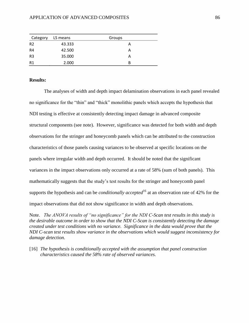
APPLICATION OF ADVANCED COMPOSITES 86
Category LS means Groups R2 43.333 A R4 42.500
A
R3 35.000
A R1 2.000 B
Results:
The analyses of width and depth impact delamination observations in each panel revealed
no significance for the “thin” and “thick” monolithic panels which accepts the hypothesis that
NDI testing is effective at consistently detecting impact damage in advanced composite
structural components (see note). However, significance was detected for both width and depth
observations for the stringer and honeycomb panels which can be attributed to the construction
characteristics of those panels causing variances to be observed at specific locations on the
panels where irregular width and depth occurred. It should be noted that the significant
variances in the impact observations only occurred at a rate of 58% (sum of both panels). This
mathematically suggests that the study’s test results for the stringer and honeycomb panel
supports the hypothesis and can be conditionally accepted16
at an observation rate of 42% for the
impact observations that did not show significance in width and depth observations.
Note. The ANOVA results of “no significance” for the NDI C-Scan test results in this study is
the desirable outcome in order to show that the NDI C-Scan is consistently detecting the damage
created under test conditions with no variance. Significance in the data would prove that the
NDI C-scan test results show variance in the observations which would suggest inconsistency for
damage detection.
[16] The hypothesis is conditionally accepted with the assumption that panel construction
characteristics caused the 58% rate of observed variances.
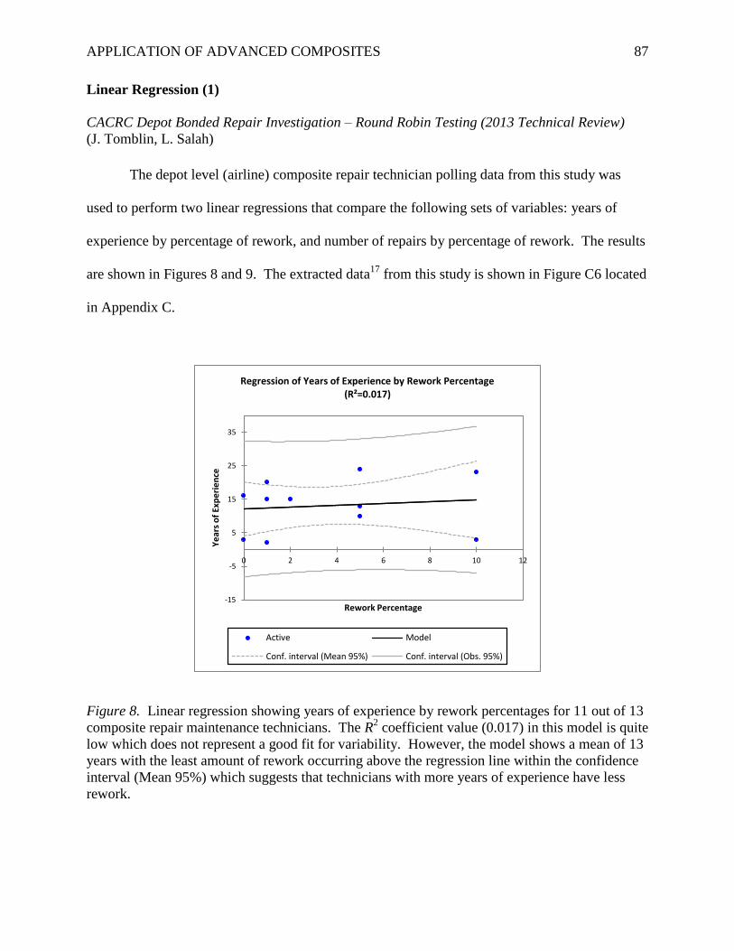
APPLICATION OF ADVANCED COMPOSITES 87
Linear Regression (1)
CACRC Depot Bonded Repair Investigation – Round Robin Testing (2013 Technical Review)
(J. Tomblin, L. Salah)
The depot level (airline) composite repair technician polling data from this study was
used to perform two linear regressions that compare the following sets of variables: years of
experience by percentage of rework, and number of repairs by percentage of rework. The results
are shown in Figures 8 and 9. The extracted data17
from this study is shown in Figure C6 located
in Appendix C.
Figure 8. Linear regression showing years of experience by rework percentages for 11 out of 13
composite repair maintenance technicians. The R2 coefficient value (0.017) in this model is quite
low which does not represent a good fit for variability. However, the model shows a mean of 13
years with the least amount of rework occurring above the regression line within the confidence
interval (Mean 95%) which suggests that technicians with more years of experience have less
rework.
-15
-5
5
15
25
35
0 2 4 6 8 10 12
Ye
ars
of
Exp
eri
en
ce
Rework Percentage
Regression of Years of Experience by Rework Percentage (R²=0.017)
Active Model
Conf. interval (Mean 95%) Conf. interval (Obs. 95%)
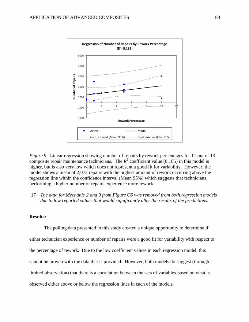
APPLICATION OF ADVANCED COMPOSITES 88
Figure 9. Linear regression showing number of repairs by rework percentages for 11 out of 13
composite repair maintenance technicians. The R2 coefficient value (0.185) in this model is
higher, but is also very low which does not represent a good fit for variability. However, the
model shows a mean of 2,072 repairs with the highest amount of rework occurring above the
regression line within the confidence interval (Mean 95%) which suggests that technicians
performing a higher number of repairs experience more rework.
[17] The data for Mechanic 2 and 9 from Figure C6 was removed from both regression models
due to low reported values that would significantly alter the results of the predictions.
Results:
The polling data presented in this study created a unique opportunity to determine if
either technician experience or number of repairs were a good fit for variability with respect to
the percentage of rework. Due to the low coefficient values in each regression model, this
cannot be proven with the data that is provided. However, both models do suggest (through
limited observation) that there is a correlation between the sets of variables based on what is
observed either above or below the regression lines in each of the models.
-3000
-1000
1000
3000
5000
7000
9000
0 2 4 6 8 10 12
Nu
mb
er
of
Re
pai
rs
Rework Percentage
Regression of Number of Repairs by Rework Percentage (R²=0.185)
Active Model
Conf. interval (Mean 95%) Conf. interval (Obs. 95%)
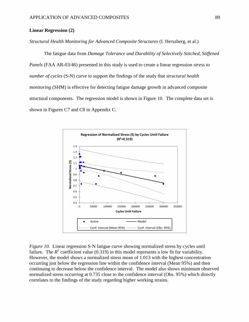
APPLICATION OF ADVANCED COMPOSITES 89
Linear Regression (2)
Structural Health Monitoring for Advanced Composite Structures (I. Herszberg, et al.)
The fatigue data from Damage Tolerance and Durability of Selectively Stitched, Stiffened
Panels (FAA AR-03/46) presented in this study is used to create a linear regression stress to
number of cycles (S-N) curve to support the findings of the study that structural health
monitoring (SHM) is effective for detecting fatigue damage growth in advanced composite
structural components. The regression model is shown in Figure 10. The complete data set is
shown in Figures C7 and C8 in Appendix C.
Figure 10. Linear regression S-N fatigue curve showing normalized stress by cycles until
failure. The R2 coefficient value (0.319) in this model represents a low fit for variability.
However, the model shows a normalized stress mean of 1.013 with the highest concentration
occurring just below the regression line within the confidence interval (Mean 95%) and then
continuing to decrease below the confidence interval. The model also shows minimum observed
normalized stress occurring at 0.735 close to the confidence interval (Obs. 95%) which directly
correlates to the findings of the study regarding higher working strains.
0.4
0.5
0.6
0.7
0.8
0.9
1
1.1
1.2
1.3
1.4
0 50000 100000 150000 200000 250000 300000 350000
No
rmal
ize
d S
tre
ss (
S)
Cycles Until Failure
Regression of Normalized Stress (S) by Cycles Until Failure (R²=0.319)
Active Model
Conf. interval (Mean 95%) Conf. interval (Obs. 95%)
APPLICATION OF ADVANCED COMPOSITES 90
Results:
The S-N linear regression fatigue curve revealed a normalized stress (minimum)
observation of the FAA AR-03/46 fatigue data to be 73.5% (static strength) which directly
correlates to the study’s predicted fatigue curve for SHM damage growth detection of 70% to
75% and further states that:
In the event that SHM systems facilitate the use of higher design allowables, the extent
of these improvements may be limited by fatigue considerations. A no-growth approach
to composite fatigue substantiation is practical because of low design allowables and
correspondingly low operating strain levels together with the characteristic flat S-N curve
for composite structures. For typical carbon fiber reinforced composites, significant
fatigue damage occurs only at strain levels above approximately 60% of static strength.
However, once growth commences, its progression is generally rapid and, consequently,
the no-growth option for composites is currently applied (Herszberg et al., n.d., para.
5.2).
Based on the findings in this study and the S-N regression modeling results for the AR-03/46
fatigue test data, SHM will be critical for the detection and monitoring of fatigue damage in
structural composite components that are under higher design loads. As this study points out,
significant fatigue damage in carbon fiber composite structures occurs at strain levels above 60%
of the static strength. This is observed in the regression model which shows failure starting to
occurring at 73.5% with the highest number of failure observations occurring just above 100%.
However, it should be noted (as stated in the study) that due to the rapid progression of fatigue
damage growth in composite structures, a no-growth approach must be maintained in order to
prevent failure from occurring; SHM is the only enabler for this approach through early detection
of fatigue damage and will prove to be vital in large applications such as the 787 and A350.
APPLICATION OF ADVANCED COMPOSITES 91
Analysis Summary
Composite Materials Studies Meta-Analysis
The findings of the meta-analysis revealed that industry-wide comprehensive process
improvements and standardization are occurring for validation testing, certification standards,
and maintenance/repair procedures of advanced composite structures used for the construction of
commercial transport aircraft. However, it should be noted that even though significant progress
is being made towards the standardization of composite maintenance and repair procedures by
the CACRC, current deficiencies in technician experience, training, and repair inspection at the
airline level do not presently support standardized composite maintenance and repair processes
within the airline industry.
ANOVA and Linear Regression Analyses
ANOVA (1) proved that that the research presented was effective at evaluating the
characteristics of the ASTM D3762 metal wedge crack durability test in order to propose
effective revisions for this validation testing methodology to be used for future assessment and
reliability testing of adhesively bonded aircraft structures. ANOVA (2) proved that non-
destructive inspection (NDI) testing is effective at consistently detecting impact damage in
advanced composite structural components by analyzing the C-Scan consistency of width and
depth impact damage observations. Linear Regression (1) showed limited modeling prediction
for airline composite repair technician experience and number of repairs variability with respect
to the percentage of rework. Linear Regression (2) proved that structural health monitoring
(SHM) will be critical for the detection and monitoring of fatigue damage in structural composite
components that are under higher design loads.
APPLICATION OF ADVANCED COMPOSITES 92
Recommendations
Based on the interpretation and inferences of the findings in this project with respect to
the identification and examination of current industry concerns and problems regarding the use
of advanced composites in commercial transport aircraft applications, and current
implementation of industry-wide comprehensive process improvements for the promulgation of
improved structural validation testing, certification, and standardized repair procedures, the
following recommendations are suggested for sustainment:
1. Manufacturer Collaboration. Boeing and Airbus will need to share and compare in-
service structural data for the 787 Dreamliner and A350 XWB in order to identify commonalities
pertaining to design, manufacturing, or maintenance concerns that have the potential to impact
safety-of-flight. This should be accomplished through extensive NDI and SHM utilization.
2. Continued Standardization. Robust FAA partnership research and industry
collaboration should continue in order to improve testing standardization and certification
processes. Manufacturers need to collaborate with the CACRC and the airlines in order to
partner for the development and establishment of standardized composite materials maintenance
training and repair procedures for use throughout the industry – model training and certification
programs (military) should be investigated and evaluated by the CACRC for potential industry-
wide implementation.
3. Active Structural Evaluation. This should be implemented for the detection of
defects, damage, and insipient failure. Robust NDI and SHM system utilization will be needed
to create a preemptive evaluative approach. Implementing this type of methodology will allow
for early detection and mitigation. Don’t wait until it breaks!
APPLICATION OF ADVANCED COMPOSITES 93
Conclusion
Accomplishments
Specific tasks and milestones were completed for this project. The first task and
milestone involved a visit to the U.S. Navy’s Advanced Composite Repair School at Naval Air
Station North Island in San Diego, CA (December, 2012). This allowed for observation of
artisan training, as well as advanced composite structures familiarization prior to literature
review. The second task and milestone was the attendance of the 2013 JAMS/CMH-17 PMC
meeting at the Boeing Future of Flight Facility in Everett, WA (April, 2013) where valuable
research was conducted with over 200 industry participants which also allowed for interviews to
be conducted with key research professionals and FAA Administrators. While attending the
meeting, the author of this project was invited to join the CMH-17 sandwich composite working
group and will be contributing to the technical review of MIL-23 Handbook chapters for the
publishing of CMH-17 Volume 6.
Benefits to Aviation
Potential benefits to aviation from this research include the identification and validation
of industry concerns associated with the continued use of advanced composites for structural
aerospace applications. It is the desire of the project’s author that the findings and
recommendations from this research are reviewed by industry professionals in order to provide
an independent exploratory perspective for future research.
Future Direction
This project contains many specific topics that can be researched independently and
presented to the FAA’s Joint Advanced Materials & Structures Center of Excellence for industry
benefit. It is the desire of the project’s author to continue this research with Embry-Riddle
Aeronautical University under the Aviation Doctorate program of study.
APPLICATION OF ADVANCED COMPOSITES 94
References
References marked with an asterisk indicate studies included in the meta-analysis.
Acellent Technologies, Inc. (n.d.). Aerospace [Fact sheet]. Retrieved from
http://www.acellentsensors.com/Aerospace.asp
*Adams, D., DeVries, L., & Child, C. (2011, April). Durability of adhesively bonded joints for
aircraft structures. Paper presented at the Joint Advanced Materials & Structures Center
of Excellence, San Diego, CA. Retrieved from
http://www.niar.wichita.edu/niarworkshops/Portals/0/Utah%20JAMS%20Adhesive%20
Durability%20April%2020%202011.pdf
*Adams, D., & Kuramoto, B. (2012, April). Damage tolerance test method development for
sandwich composites. Paper presented at the Joint Advanced Materials & Structures
Center of Excellence, San Diego, CA. Retrieved from
http://depts.washington.edu/amtas/events/jams_12/presentations/3.Adams-
DamageTolerance.pdf
Ahrens, C. D. (2009). Meteorology today (9th ed.). Belmont, CA: Brooks/Cole.
Anderson, Jr., J. D. (2008). Introduction to flight (6th ed.). New York, NY: McGraw-Hill.
Boeing 787 from the ground up. [Entire issue]. (2006). AERO Magazine. Retrieved from
http://www.boeing.com/commercial/aeromagazine
Buckley, J. (2006, November). A comparison of techniques for ultrasonic inspection of
composite materials. Paper presented at the Asia-Pacific Conference on Non-Destructive
Testing, Auckland, New Zealand. Retrieved from
http://www.ndt.net/article/apcndt2006/papers/81.pdf
APPLICATION OF ADVANCED COMPOSITES 95
Commercial Aircraft Composite Repair Committee. (n.d.). Committee information
[Informational presentation]. Retrieved from
http://www.sae.org/works/committeeHome.do?comtID=TEAAMSCACRC
Dassault Systemes. (n.d.). SIMULIA realistic simulation [Fact sheet]. Retrieved from
http://www.3ds.com/products/simulia
Dexmet Corporation. (2007). Lightning strike protection for carbon fiber aircraft [Conference
paper]. Retrieved from
http://www.dexmet.com/1_pdf/LSP%20for%20Carbon%20Fiber%20Aircraft.pdf
FAA creates center of excellence for advanced materials. (n.d.). Retrieved from
http://www.jams-coe.org/mx/hm.asp?id=History
*Fawcett, A. J., & Oakes, G. D. (n.d.). Boeing composite airframe damage tolerance and service
experience. Retrieved from The Boeing Company: http://servidor-
da.aero.upm.es/wip/apuntes/quinto/materiales-
compuestos/tolerancia%20al%20dano.pdf.pdf
Federal Aviation Administration. (2009). Composite aircraft structure (FAA Advisory Circular
No. AC 20-107B). Retrieved from
http://www.faa.gov/documentLibrary/media/Advisory_Circular/AC20-107B.pdf
Fielding, J. P. (1999). Introduction to aircraft design. New York, NY: Cambridge University
Press.
Garland, D. J., Wise, J. A., & Hopkin, V. D. (1999). Handbook of aviation human factors.
Mahwah, NJ: Lawrence Erlbaum Associates.
Government Printing Office. (1990). Part 25 Airworthiness standards: Transport category
airplanes (CFR Document No. 5066, AMD 25-72, 55 FR 29775). Washington, DC:
Government Printing Office.
APPLICATION OF ADVANCED COMPOSITES 96
Hahn, H. T., Yang, J. M., Suh, S., Yi, T., & Wu, G. (2003). Damage tolerance and durability of
selectively stitched, stiffened panels (FAA AR-03/46). Retrieved from Federal Aviation
Administration website: http://www.tc.faa.gov/its/worldpac/techrpt/ar03-46.pdf
Hawkins, F. H. (1993). Human factors in flight (2nd ed.). Burlington, VT: Ashgate.
*Heida, J. H., & Platenkamp, D. J. (2012, April). In-service inspection guidelines for composite
aerospace structures. Paper presented at the World Conference on Non-Destructive
Testing, Durban, South Africa. Retrieved from
http://www.ndt.net/article/wcndt2012/papers/33_Heida_Rev1.pdf
*Herszberg, I., Bannister, M. K., Li, H. C., Thomson, R. S., & White, C. (n.d.). Structural health
monitoring for advanced composite structures. Retrieved from Cooperative Research
Centre for Advanced Composite Structures Limited: http://www.iccm-
central.org/Proceedings/ICCM16proceedings/contents/pdf/Pl/Pl-
03pl_herszbergi223401p.pdf
High airline jet fuel costs prompt cost-savings measures. (2012). Retrieved from
http://www.eia.gov/todayinenergy/detail.cfm?id=6670
*Ilcewicz, L. (2010, May). FAA composite safety administration and certification initiatives.
Paper presented at the Joint Advanced Materials & Structures Center of Excellence,
Seattle, WA. Retrieved from
http://depts.washington.edu/amtas/events/jams_10/Ilcewicz.pdf
Kanki, B. G., Helmreich, R. L., & Anca, J. (2010). Crew Resource Management (2nd ed.). San
Diego, CA: Elsevier, Academic Press.
*Kim, H. (2012, April). Impact damage formation on composite aircraft structures. Paper
presented at the Joint Advanced Materials & Structures Center of Excellence, Everett,
WA. Retrieved from
APPLICATION OF ADVANCED COMPOSITES 97
http://www.niar.wichita.edu/coe/cecam/Impact_Damage_Formation_on_Composite_Airc
raft_Structures-Kim.pdf
Lin, M., Qing, X., Kumar, A., & Beard, S. J. (2005). Smart layer and smart suitcase for
structural health monitoring applications (Missile Defense Agency/Acellent
Technologies, Inc.). Retrieved from The Defense Technical Information Center website:
http://www.dtic.mil/cgi-bin/GetTRDoc?AD=ADA442244
Marshall, T. (n.d.). NDT inspection of composites for in-service defects. Retrieved from NET
Composites website: http://www.netcomposites.com/downloads/07_ndt_marshall.pdf
NDT Education Resource Center. (n.d.). Composite structures [Educational standards].
Retrieved from http://www.ndt-
ed.org/EducationResources/CommunityCollege/Materials/Structure/composite_class.htm
NSE Composites. (n.d.). Typical aerospace projects [Fact sheet]. Retrieved from
http://nsecomposites.com/projects/aerospace
Naval Air Systems Command. (2011). General composite repair (01-1A-21 Change 1 ed.).
[Adobe Digital Editions]. Retrieved from https://mynatec.navair.navy.mil/
Ohlemiller, T. J., & Shields, J. R. (1998). Effect of surface coatings on fire growth over
composite materials in a corner configuration (Fire Safety Journal, Vol. 32, 173-193,
1999). Retrieved from The National Institute of Standards and Technology website:
http://fire.nist.gov/bfrlpubs/fire99/PDF/f99021.pdf
Oil: Crude and petroleum products explained. (n.d.). Retrieved from
http://www.eia.gov/energyexplained/index.cfm?page=oil_refining#tab1
Osterc, P., Kim, D., & Yoo, B. (2012). Phased array beamsteering in composite laminates for
guided wave structural health monitoring. Embry-Riddle Aeronautical University:
Author.
APPLICATION OF ADVANCED COMPOSITES 98
Salah, L. (2013, April). CACRC depot bonded repair investigation – round robin testing. Paper
presented at the Joint Advanced Materials & Structures Center of Excellence, Everett,
WA. Retrieved from
http://depts.washington.edu/amtas/events/jams_12/presentations/7.Salah.pdf
Seneviratne, W. (2008, June). Damage tolerance testing and analysis protocols for full-scale
composite airframe structures under repeated loading. Paper presented at the Joint
Advanced Materials & Structures Center of Excellence, Everett, WA. Retrieved from
http://depts.washington.edu/amtas/events/jams_08/4.Seneviratne.pdf
Severson, M. D. (2012). Composite aircraft structure vulnerability to lightning strikes [Research
paper]. Embry-Riddle Aeronautical University, Worldwide: Author.
Stickler, P. B. (2002). Composite materials for commercial transport - issues and future
research direction. Retrieved from Texas A&M University ALPHA website:
http://alpha.tamu.edu/public/temp/asc17/stickler.pdf
The Boeing Company. (2012). 787 aircraft rescue & firefighting [Test results presentation].
Retrieved from http://www.boeing.com/commercial/airports/misc/787_arff_data.pdf
The Boeing Company. (n.d.). 787 Dreamliner [Fact sheet]. Retrieved from
http://www.boeing.com/boeing/commercial/787family/programfacts.page
Tidd, J., & Bessant, J. (2009). Managing innovation: Integrating technological, market and
organizational change (4th ed.). West Sussex, England: John Wiley & Sons.
*Tomblin, J., & Salah, L. (2012, April). CACRC depot bonded repair investigation – round
robin testing. Paper presented at the Joint Advanced Materials & Structures Center of
Excellence, Baltimore, MD. Retrieved from
http://depts.washington.edu/amtas/events/jams_12/presentations/7.Salah.pdf
APPLICATION OF ADVANCED COMPOSITES 99
*Tomblin, J., & Salah, L. (2013, April). CACRC depot bonded repair investigation – round
robin testing. Paper presented at the Joint Advanced Materials & Structures Center of
Excellence, Everett, WA. Retrieved from
http://www.niar.wichita.edu/coe/cecam/CACRC-Lamia.pdf
*Tomblin, J., Salah, L., & Yang, C. (2005, May). Effects of repair procedures applied to
composite airframe structures. Paper presented at the Joint Advanced Materials &
Structures Center of Excellence, Wichita, KS. Retrieved from http://www.jams-
coe.org/docs/Tuesday%20Afternoon05/Salah.pdf
*Tomblin, J., Salah, L., & Yang, C. (2006, June). Effects of repair procedures applied to
composite airframe structures. Paper presented at the Joint Advanced Materials &
Structures Center of Excellence, Seattle, WA. Retrieved from
http://depts.washington.edu/amtas/events/jams_06/Salah_Repair.pdf
*Tomblin, J., & Seneviratne, W. (2008, June). Damage tolerance testing and analysis protocols
for full-scale composite airframe structures under repeated loading. Paper presented at
the Joint Advanced Materials & Structures Center of Excellence, Everett, WA. Retrieved
from http://depts.washington.edu/amtas/events/jams_08/4.Seneviratne.pdf
*Tuttle, M., Shifman, T., & Boursier, B. (2013, April). Simplifying certification of discontinuous
composite material forms for primary aircraft structures. Paper presented at the Joint
Advanced Materials & Structures Center of Excellence, Everett, WA. Retrieved from
http://www.niar.wichita.edu/coe/cecam/Certification_of_Discontinuous_Fiber_Composit
e_Forms_for_Aircraft_Structures-Tuttle.pdf
U.S. Environmental Protection Agency. (2000). Pursuing perfection: Case studies examining
lean manufacturing strategies, pollution prevention, and environmental regulatory
APPLICATION OF ADVANCED COMPOSITES 100
management implications. Retrieved from
http://www.epa.gov/lean/environment/pdf/perfection.pdf
*U.S. Government Accountability Office. (2011). Status of FAA’s actions to oversee the safety
of composite airplanes (GAO-11-849). Washington, DC: Government Printing Office.
Wells, A. T., & Rodrigues, C. C. (2004). The Federal Aviation Administration (FAA). In
Commercial aviation safety (4th ed. (pp. 2-12). New York, NY: McGraw-Hill.
Wells, A. T., & Wensveen, J. G. (2004). The aerospace industry. In Air transportation: A
management perspective (5th ed. (pp. 4-31). Belmont, CA: Brooks/Cole - Thomson
Learning.
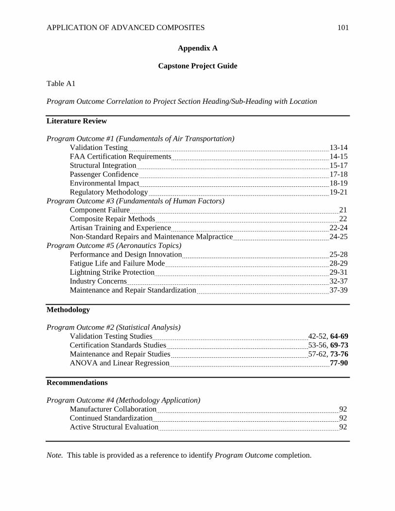
APPLICATION OF ADVANCED COMPOSITES 101
Appendix A
Capstone Project Guide
Table A1
Program Outcome Correlation to Project Section Heading/Sub-Heading with Location
Literature Review
Program Outcome #1 (Fundamentals of Air Transportation)
Validation Testing 13-14
FAA Certification Requirements 14-15
Structural Integration 15-17
Passenger Confidence 17-18
Environmental Impact 18-19
Regulatory Methodology 19-21
Program Outcome #3 (Fundamentals of Human Factors)
Component Failure 21
Composite Repair Methods 22
Artisan Training and Experience 22-24
Non-Standard Repairs and Maintenance Malpractice 24-25
Program Outcome #5 (Aeronautics Topics)
Performance and Design Innovation 25-28
Fatigue Life and Failure Mode 28-29
Lightning Strike Protection 29-31
Industry Concerns 32-37
Maintenance and Repair Standardization 37-39
Methodology
Program Outcome #2 (Statistical Analysis)
Validation Testing Studies 42-52, 64-69
Certification Standards Studies 53-56, 69-73
Maintenance and Repair Studies 57-62, 73-76
ANOVA and Linear Regression 77-90
Recommendations
Program Outcome #4 (Methodology Application)
Manufacturer Collaboration 92
Continued Standardization 92
Active Structural Evaluation 92
Note. This table is provided as a reference to identify Program Outcome completion.
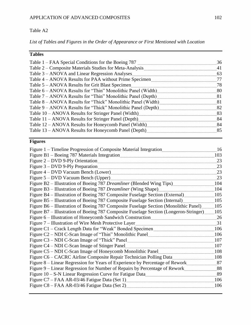
APPLICATION OF ADVANCED COMPOSITES 102
Table A2
List of Tables and Figures in the Order of Appearance or First Mentioned with Location
Tables
Table 1 – FAA Special Conditions for the Boeing 787 36
Table 2 – Composite Materials Studies for Meta-Analysis 41
Table 3 – ANOVA and Linear Regression Analyses 63
Table 4 – ANOVA Results for PAA without Prime Specimen 77
Table 5 – ANOVA Results for Grit Blast Specimen 78
Table 6 – ANOVA Results for “Thin” Monolithic Panel (Width) 80
Table 7 – ANOVA Results for “Thin” Monolithic Panel (Depth) 81
Table 8 – ANOVA Results for “Thick” Monolithic Panel (Width) 81
Table 9 – ANOVA Results for “Thick” Monolithic Panel (Depth) 82
Table 10 – ANOVA Results for Stringer Panel (Width) 83
Table 11 – ANOVA Results for Stringer Panel (Depth) 84
Table 12 – ANOVA Results for Honeycomb Panel (Width) 84
Table 13 – ANOVA Results for Honeycomb Panel (Depth) 85
Figures
Figure 1 – Timeline Progression of Composite Material Integration 16
Figure B1 – Boeing 787 Materials Integration 103
Figure 2 – DVD 9-Ply Orientation 23
Figure 3 – DVD 9-Ply Preparation 23
Figure 4 – DVD Vacuum Bench (Lower) 23
Figure 5 – DVD Vacuum Bench (Upper) 23
Figure B2 – Illustration of Boeing 787 Dreamliner (Blended Wing Tips) 104
Figure B3 – Illustration of Boeing 787 Dreamliner (Wing Shape) 104
Figure B4 – Illustration of Boeing 787 Composite Fuselage Section (External) 105
Figure B5 – Illustration of Boeing 787 Composite Fuselage Section (Internal) 105
Figure B6 – Illustration of Boeing 787 Composite Fuselage Section (Monolithic Panel) 105
Figure B7 – Illustration of Boeing 787 Composite Fuselage Section (Longeron-Stringer) 105
Figure 6 – Illustration of Honeycomb Sandwich Construction 26
Figure 7 – Illustration of Wire Mesh Protective Layer 31
Figure C1 – Crack Length Data for “Weak” Bonded Specimen 106
Figure C2 – NDI C-Scan Image of “Thin” Monolithic Panel 106
Figure C3 – NDI C-Scan Image of “Thick” Panel 107
Figure C4 – NDI C-Scan Image of Stinger Panel 107
Figure C5 – NDI C-Scan Image of Honeycomb Monolithic Panel 108
Figure C6 – CACRC Airline Composite Repair Technician Polling Data 108
Figure 8 – Linear Regression for Years of Experience by Percentage of Rework 87
Figure 9 – Linear Regression for Number of Repairs by Percentage of Rework 88
Figure 10 – S-N Linear Regression Curve for Fatigue Data 89
Figure C7 – FAA AR-03/46 Fatigue Data (Set 1) 106
Figure C8 – FAA AR-03/46 Fatigue Data (Set 2) 106
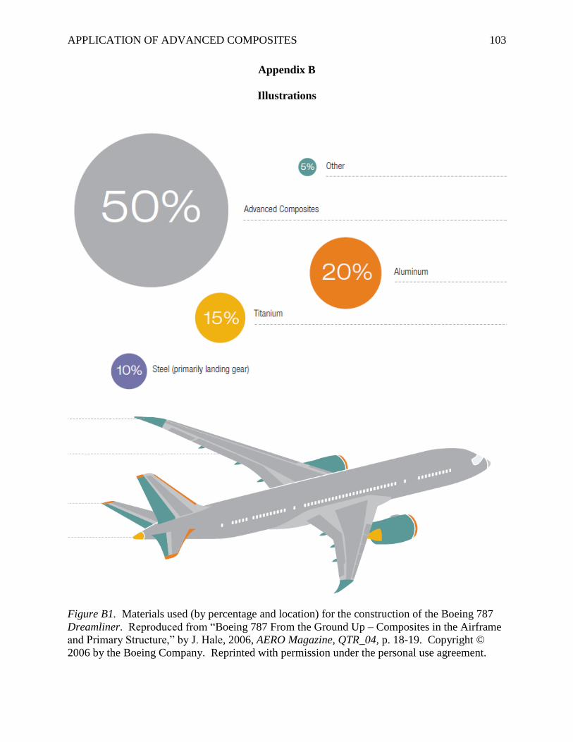
APPLICATION OF ADVANCED COMPOSITES 103
Appendix B
Illustrations
Figure B1. Materials used (by percentage and location) for the construction of the Boeing 787
Dreamliner. Reproduced from “Boeing 787 From the Ground Up – Composites in the Airframe
and Primary Structure,” by J. Hale, 2006, AERO Magazine, QTR_04, p. 18-19. Copyright ©
2006 by the Boeing Company. Reprinted with permission under the personal use agreement.
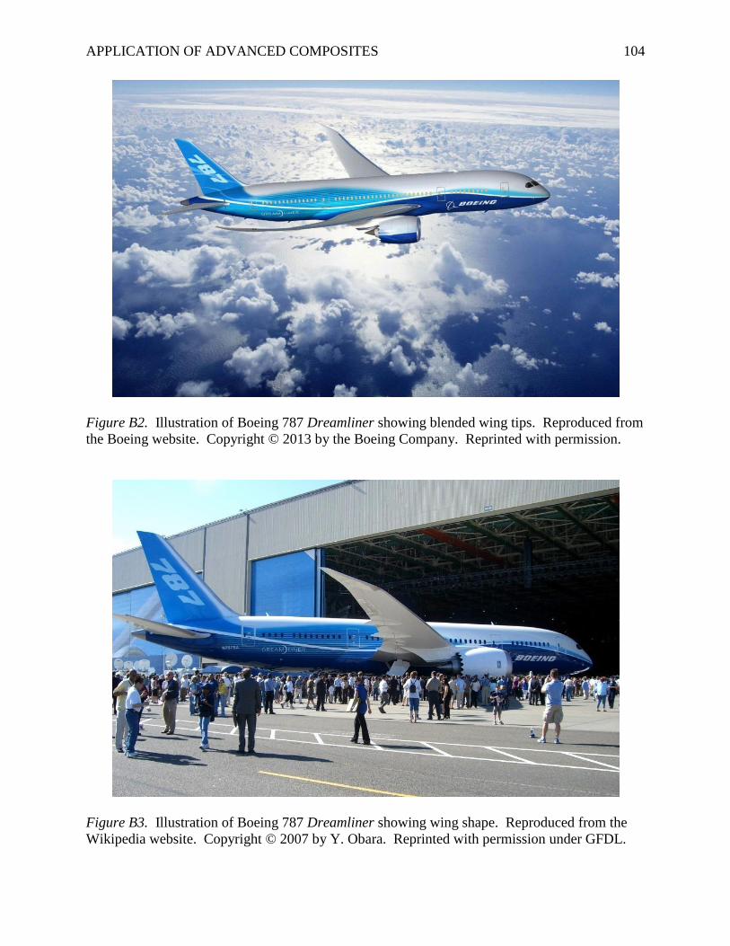
APPLICATION OF ADVANCED COMPOSITES 104
Figure B2. Illustration of Boeing 787 Dreamliner showing blended wing tips. Reproduced from
the Boeing website. Copyright © 2013 by the Boeing Company. Reprinted with permission.
Figure B3. Illustration of Boeing 787 Dreamliner showing wing shape. Reproduced from the
Wikipedia website. Copyright © 2007 by Y. Obara. Reprinted with permission under GFDL.
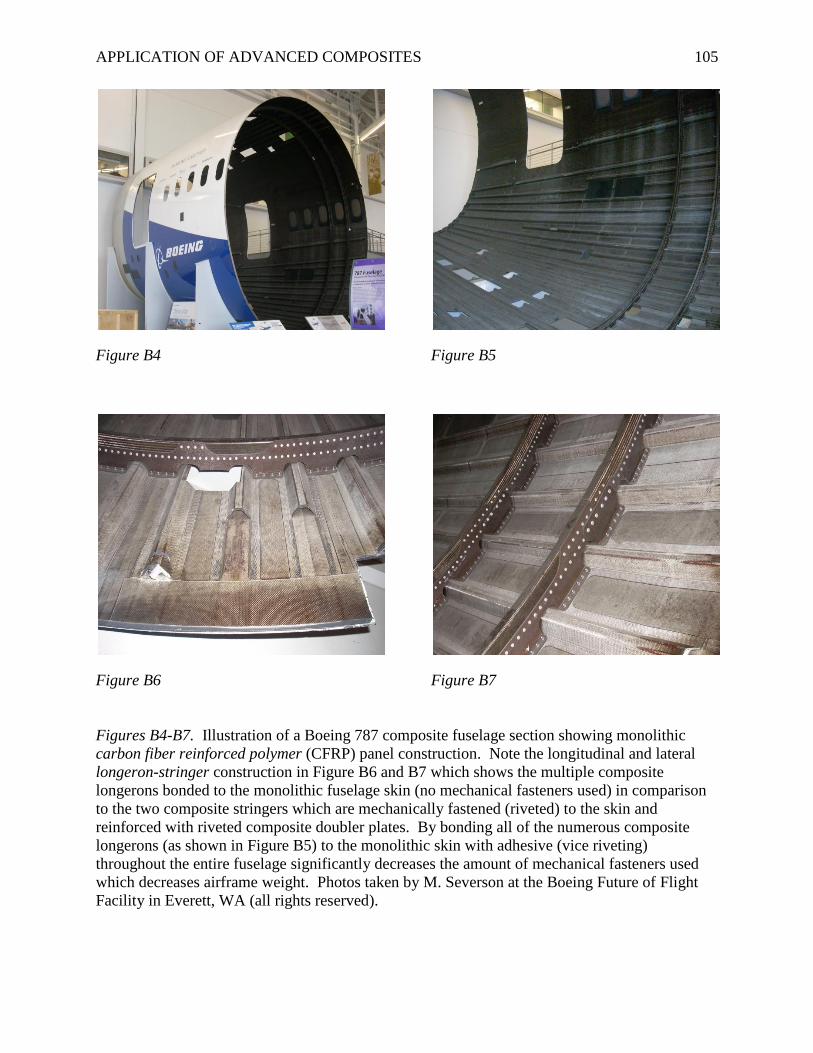
APPLICATION OF ADVANCED COMPOSITES 105
Figure B4 Figure B5
Figure B6 Figure B7
Figures B4-B7. Illustration of a Boeing 787 composite fuselage section showing monolithic
carbon fiber reinforced polymer (CFRP) panel construction. Note the longitudinal and lateral
longeron-stringer construction in Figure B6 and B7 which shows the multiple composite
longerons bonded to the monolithic fuselage skin (no mechanical fasteners used) in comparison
to the two composite stringers which are mechanically fastened (riveted) to the skin and
reinforced with riveted composite doubler plates. By bonding all of the numerous composite
longerons (as shown in Figure B5) to the monolithic skin with adhesive (vice riveting)
throughout the entire fuselage significantly decreases the amount of mechanical fasteners used
which decreases airframe weight. Photos taken by M. Severson at the Boeing Future of Flight
Facility in Everett, WA (all rights reserved).
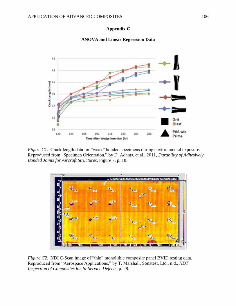
APPLICATION OF ADVANCED COMPOSITES 106
Appendix C
ANOVA and Linear Regression Data
Figure C1. Crack length data for “weak” bonded specimens during environmental exposure.
Reproduced from “Specimen Orientation,” by D. Adams, et al., 2011, Durability of Adhesively
Bonded Joints for Aircraft Structures, Figure 7, p. 18.
Figure C2. NDI C-Scan image of “thin” monolithic composite panel BVID testing data.
Reproduced from “Aerospace Applications,” by T. Marshall, Sonatest, Ltd., n.d., NDT
Inspection of Composites for In-Service Defects, p. 28.
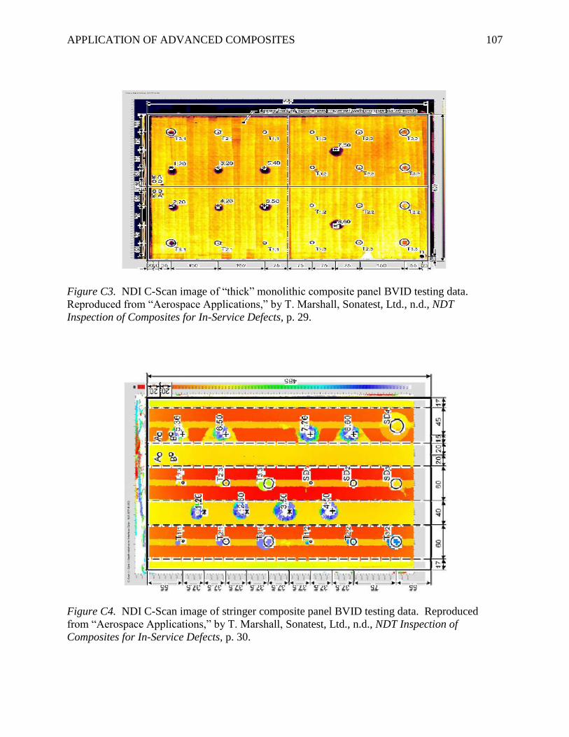
APPLICATION OF ADVANCED COMPOSITES 107
Figure C3. NDI C-Scan image of “thick” monolithic composite panel BVID testing data.
Reproduced from “Aerospace Applications,” by T. Marshall, Sonatest, Ltd., n.d., NDT
Inspection of Composites for In-Service Defects, p. 29.
Figure C4. NDI C-Scan image of stringer composite panel BVID testing data. Reproduced
from “Aerospace Applications,” by T. Marshall, Sonatest, Ltd., n.d., NDT Inspection of
Composites for In-Service Defects, p. 30.
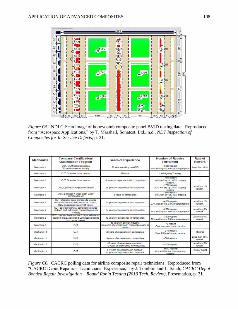
APPLICATION OF ADVANCED COMPOSITES 108
Figure C5. NDI C-Scan image of honeycomb composite panel BVID testing data. Reproduced
from “Aerospace Applications,” by T. Marshall, Sonatest, Ltd., n.d., NDT Inspection of
Composites for In-Service Defects, p. 31.
Figure C6. CACRC polling data for airline composite repair technicians. Reproduced from
“CACRC Depot Repairs – Technicians’ Experience,” by J. Tomblin and L. Salah, CACRC Depot
Bonded Repair Investigation – Round Robin Testing (2013 Tech. Review), Presentation, p. 31.
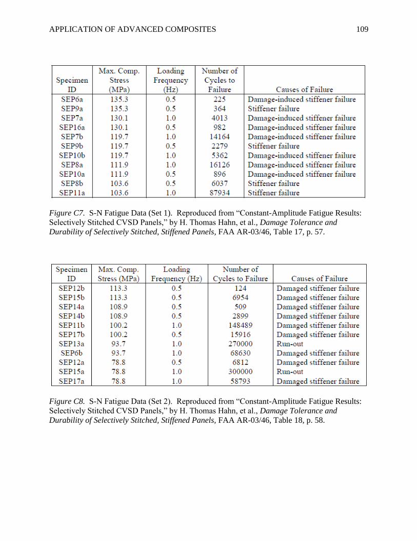
APPLICATION OF ADVANCED COMPOSITES 109
Figure C7. S-N Fatigue Data (Set 1). Reproduced from “Constant-Amplitude Fatigue Results:
Selectively Stitched CVSD Panels,” by H. Thomas Hahn, et al., Damage Tolerance and
Durability of Selectively Stitched, Stiffened Panels, FAA AR-03/46, Table 17, p. 57.
Figure C8. S-N Fatigue Data (Set 2). Reproduced from “Constant-Amplitude Fatigue Results:
Selectively Stitched CVSD Panels,” by H. Thomas Hahn, et al., Damage Tolerance and
Durability of Selectively Stitched, Stiffened Panels, FAA AR-03/46, Table 18, p. 58.
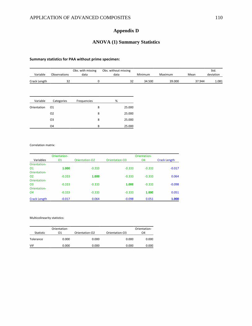
APPLICATION OF ADVANCED COMPOSITES 110
Appendix D
ANOVA (1) Summary Statistics
Summary statistics for PAA without prime specimen:
Variable Observations Obs. with missing
data Obs. without missing
data Minimum Maximum Mean Std.
deviation
Crack Length 32 0 32 34.500 39.000 37.944 1.081
Variable Categories Frequencies %
Orientation O1 8 25.000
O2 8 25.000
O3 8 25.000
O4 8 25.000
Correlation matrix:
Variables Orientation-
O1 Orientation-O2 Orientation-O3 Orientation-
O4 Crack Length Orientation-
O1 1.000 -0.333 -0.333 -0.333 -0.017 Orientation-
O2 -0.333 1.000 -0.333 -0.333 0.064 Orientation-
O3 -0.333 -0.333 1.000 -0.333 -0.098 Orientation-
O4 -0.333 -0.333 -0.333 1.000 0.051
Crack Length -0.017 0.064 -0.098 0.051 1.000
Multicolinearity statistics:
Statistic Orientation-
O1 Orientation-O2 Orientation-O3 Orientation-
O4
Tolerance 0.000 0.000 0.000 0.000
VIF 0.000 0.000 0.000 0.000
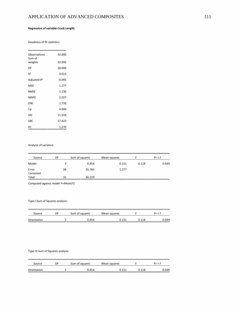
APPLICATION OF ADVANCED COMPOSITES 111
Regression of variable Crack Length:
Goodness of fit statistics:
Observations 32.000
Sum of weights 32.000
DF 28.000
R² 0.013
Adjusted R² -0.093
MSE 1.277
RMSE 1.130
MAPE 2.027
DW 1.726
Cp 4.000
AIC 11.559
SBC 17.422
PC 1.270
Analysis of variance:
Source DF Sum of squares Mean squares F Pr > F
Model 3 0.454 0.151 0.118 0.949
Error 28 35.765 1.277
Corrected Total 31 36.219
Computed against model Y=Mean(Y)
Type I Sum of Squares analysis:
Source DF Sum of squares Mean squares F Pr > F
Orientation 3 0.454 0.151 0.118 0.949
Type III Sum of Squares analysis:
Source DF Sum of squares Mean squares F Pr > F
Orientation 3 0.454 0.151 0.118 0.949
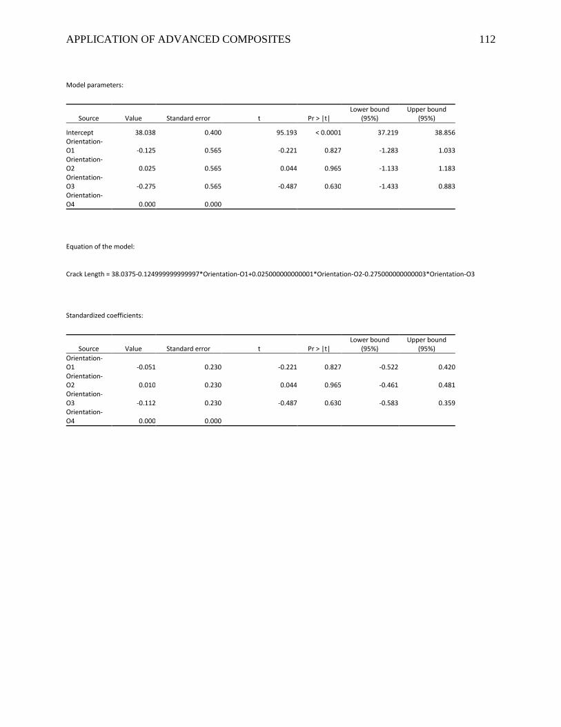
APPLICATION OF ADVANCED COMPOSITES 112
Model parameters:
Source Value Standard error t Pr > |t| Lower bound
(95%) Upper bound
(95%)
Intercept 38.038 0.400 95.193 < 0.0001 37.219 38.856 Orientation-
O1 -0.125 0.565 -0.221 0.827 -1.283 1.033 Orientation-
O2 0.025 0.565 0.044 0.965 -1.133 1.183 Orientation-
O3 -0.275 0.565 -0.487 0.630 -1.433 0.883 Orientation-
O4 0.000 0.000
Equation of the model:
Crack Length = 38.0375-0.124999999999997*Orientation-O1+0.025000000000001*Orientation-O2-0.275000000000003*Orientation-O3
Standardized coefficients:
Source Value Standard error t Pr > |t| Lower bound
(95%) Upper bound
(95%) Orientation-
O1 -0.051 0.230 -0.221 0.827 -0.522 0.420 Orientation-
O2 0.010 0.230 0.044 0.965 -0.461 0.481 Orientation-
O3 -0.112 0.230 -0.487 0.630 -0.583 0.359 Orientation-
O4 0.000 0.000
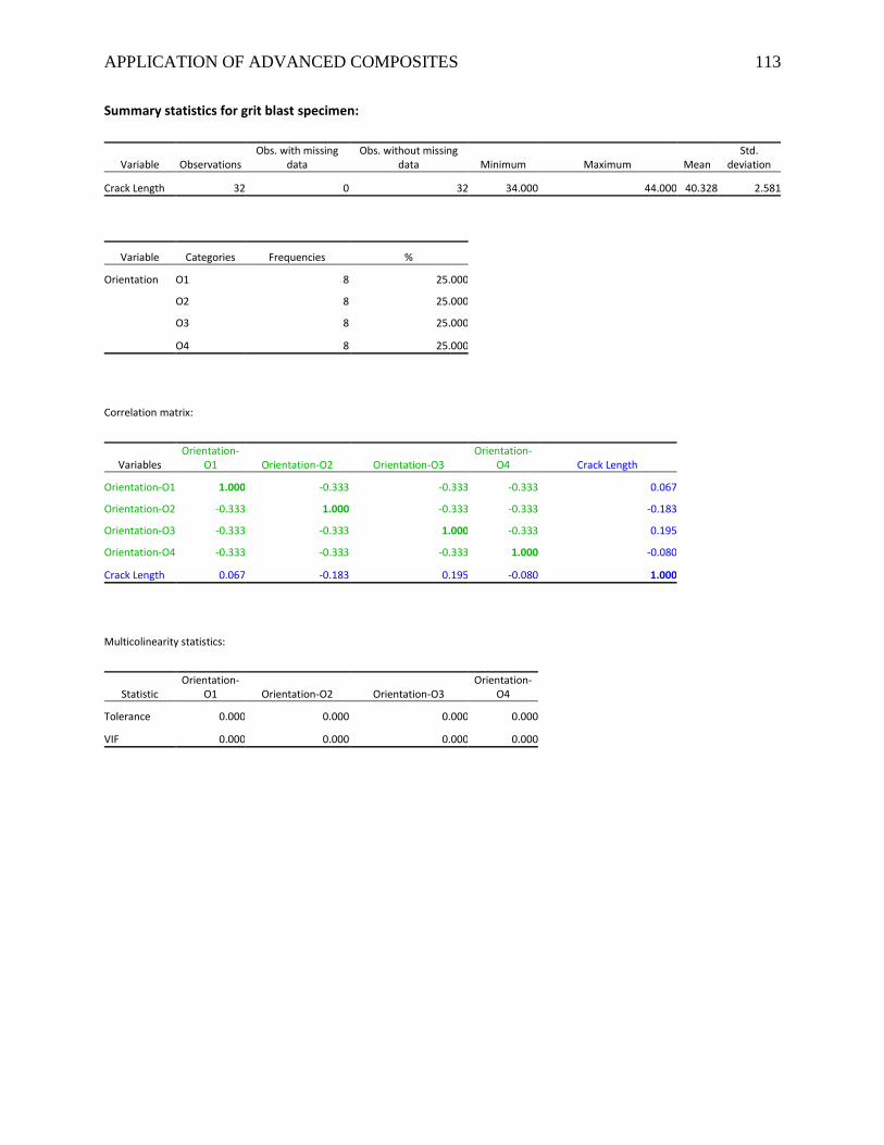
APPLICATION OF ADVANCED COMPOSITES 113
Summary statistics for grit blast specimen:
Variable Observations Obs. with missing
data Obs. without missing
data Minimum Maximum Mean Std.
deviation
Crack Length 32 0 32 34.000 44.000 40.328 2.581
Variable Categories Frequencies %
Orientation O1 8 25.000
O2 8 25.000
O3 8 25.000
O4 8 25.000
Correlation matrix:
Variables Orientation-
O1 Orientation-O2 Orientation-O3 Orientation-
O4 Crack Length
Orientation-O1 1.000 -0.333 -0.333 -0.333 0.067
Orientation-O2 -0.333 1.000 -0.333 -0.333 -0.183
Orientation-O3 -0.333 -0.333 1.000 -0.333 0.195
Orientation-O4 -0.333 -0.333 -0.333 1.000 -0.080
Crack Length 0.067 -0.183 0.195 -0.080 1.000
Multicolinearity statistics:
Statistic Orientation-
O1 Orientation-O2 Orientation-O3 Orientation-
O4
Tolerance 0.000 0.000 0.000 0.000
VIF 0.000 0.000 0.000 0.000
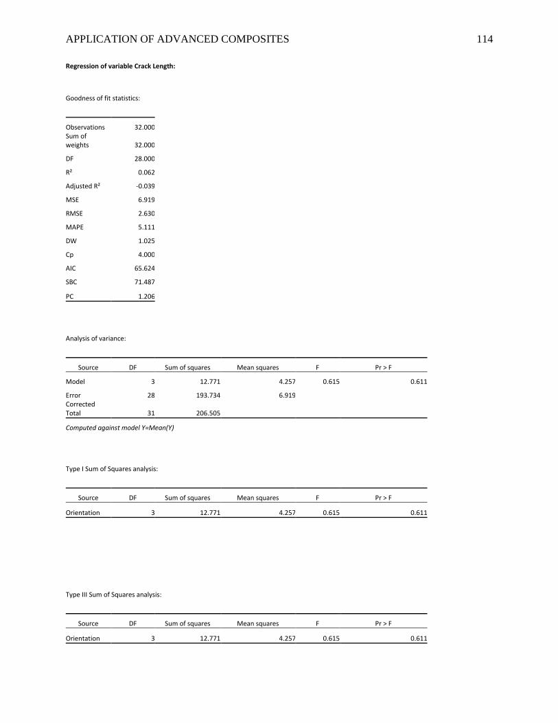
APPLICATION OF ADVANCED COMPOSITES 114
Regression of variable Crack Length:
Goodness of fit statistics:
Observations 32.000
Sum of weights 32.000
DF 28.000
R² 0.062
Adjusted R² -0.039
MSE 6.919
RMSE 2.630
MAPE 5.111
DW 1.025
Cp 4.000
AIC 65.624
SBC 71.487
PC 1.206
Analysis of variance:
Source DF Sum of squares Mean squares F Pr > F
Model 3 12.771 4.257 0.615 0.611
Error 28 193.734 6.919
Corrected Total 31 206.505
Computed against model Y=Mean(Y)
Type I Sum of Squares analysis:
Source DF Sum of squares Mean squares F Pr > F
Orientation 3 12.771 4.257 0.615 0.611
Type III Sum of Squares analysis:
Source DF Sum of squares Mean squares F Pr > F
Orientation 3 12.771 4.257 0.615 0.611
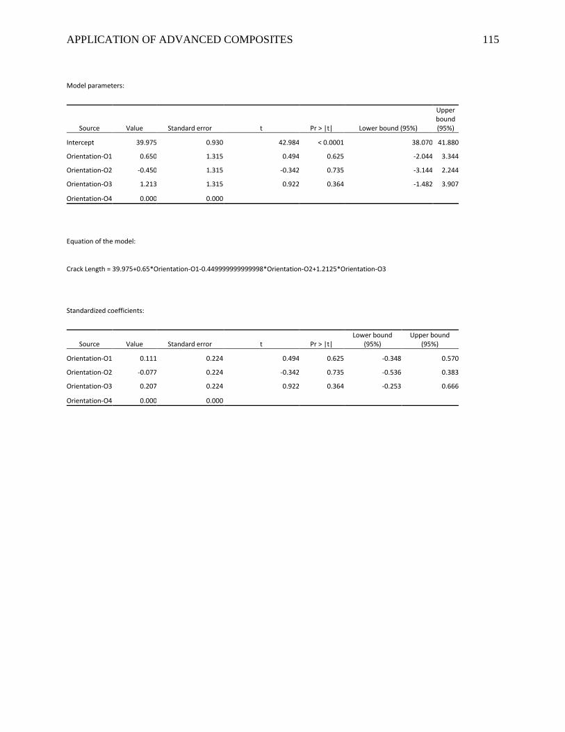
APPLICATION OF ADVANCED COMPOSITES 115
Model parameters:
Source Value Standard error t Pr > |t| Lower bound (95%)
Upper bound (95%)
Intercept 39.975 0.930 42.984 < 0.0001 38.070 41.880
Orientation-O1 0.650 1.315 0.494 0.625 -2.044 3.344
Orientation-O2 -0.450 1.315 -0.342 0.735 -3.144 2.244
Orientation-O3 1.213 1.315 0.922 0.364 -1.482 3.907
Orientation-O4 0.000 0.000
Equation of the model:
Crack Length = 39.975+0.65*Orientation-O1-0.449999999999998*Orientation-O2+1.2125*Orientation-O3
Standardized coefficients:
Source Value Standard error t Pr > |t| Lower bound
(95%) Upper bound
(95%)
Orientation-O1 0.111 0.224 0.494 0.625 -0.348 0.570
Orientation-O2 -0.077 0.224 -0.342 0.735 -0.536 0.383
Orientation-O3 0.207 0.224 0.922 0.364 -0.253 0.666
Orientation-O4 0.000 0.000
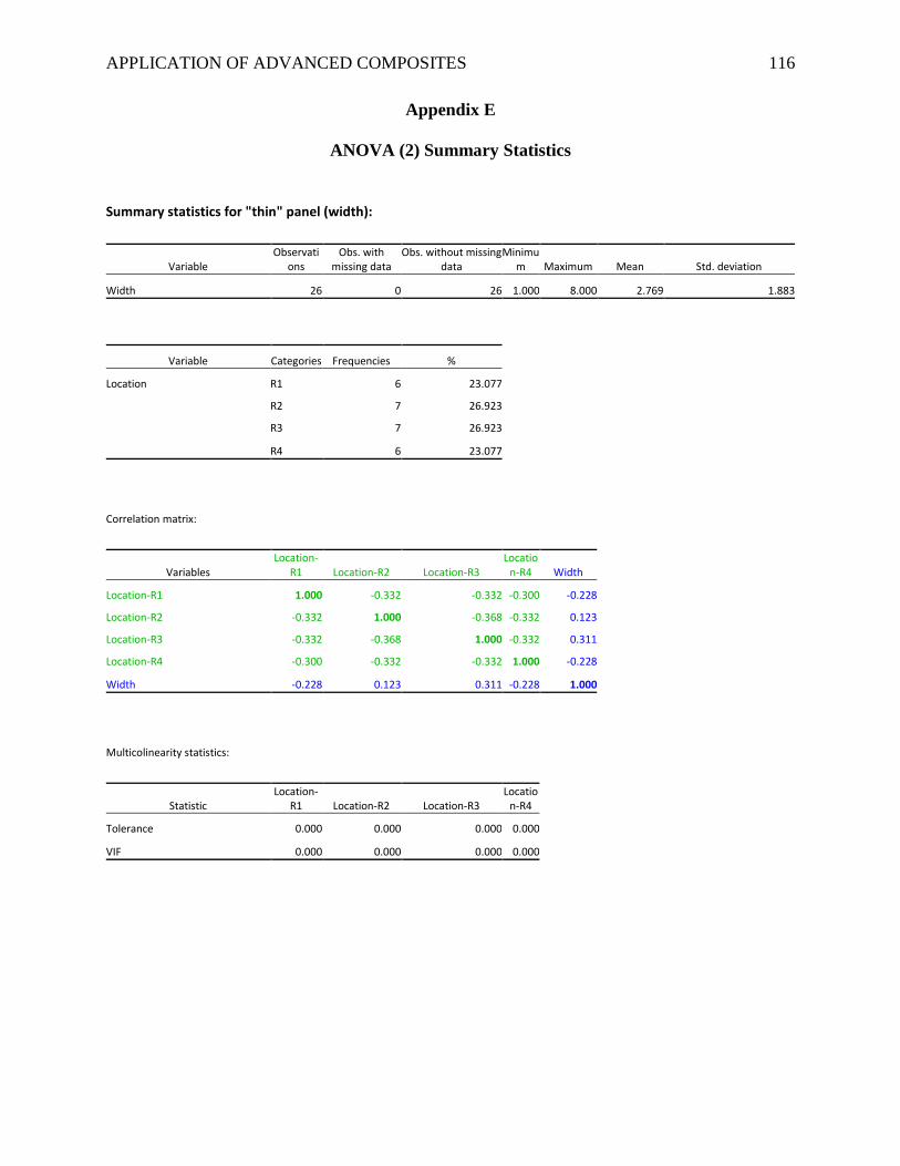
APPLICATION OF ADVANCED COMPOSITES 116
Appendix E
ANOVA (2) Summary Statistics
Summary statistics for "thin" panel (width):
Variable Observati
ons Obs. with
missing data Obs. without missing
data Minimu
m Maximum Mean Std. deviation
Width 26 0 26 1.000 8.000 2.769 1.883
Variable Categories Frequencies %
Location R1 6 23.077
R2 7 26.923
R3 7 26.923
R4 6 23.077
Correlation matrix:
Variables Location-
R1 Location-R2 Location-R3 Locatio
n-R4 Width
Location-R1 1.000 -0.332 -0.332 -0.300 -0.228
Location-R2 -0.332 1.000 -0.368 -0.332 0.123
Location-R3 -0.332 -0.368 1.000 -0.332 0.311
Location-R4 -0.300 -0.332 -0.332 1.000 -0.228
Width -0.228 0.123 0.311 -0.228 1.000
Multicolinearity statistics:
Statistic Location-
R1 Location-R2 Location-R3 Locatio
n-R4
Tolerance 0.000 0.000 0.000 0.000
VIF 0.000 0.000 0.000 0.000
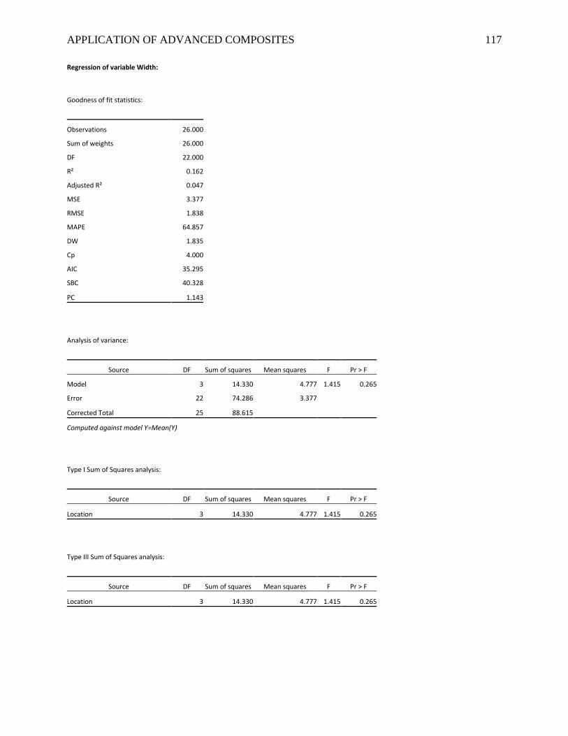
APPLICATION OF ADVANCED COMPOSITES 117
Regression of variable Width:
Goodness of fit statistics:
Observations 26.000
Sum of weights 26.000
DF 22.000
R² 0.162
Adjusted R² 0.047
MSE 3.377
RMSE 1.838
MAPE 64.857
DW 1.835
Cp 4.000
AIC 35.295
SBC 40.328
PC 1.143
Analysis of variance:
Source DF Sum of squares Mean squares F Pr > F
Model 3 14.330 4.777 1.415 0.265
Error 22 74.286 3.377
Corrected Total 25 88.615
Computed against model Y=Mean(Y)
Type I Sum of Squares analysis:
Source DF Sum of squares Mean squares F Pr > F
Location 3 14.330 4.777 1.415 0.265
Type III Sum of Squares analysis:
Source DF Sum of squares Mean squares F Pr > F
Location 3 14.330 4.777 1.415 0.265
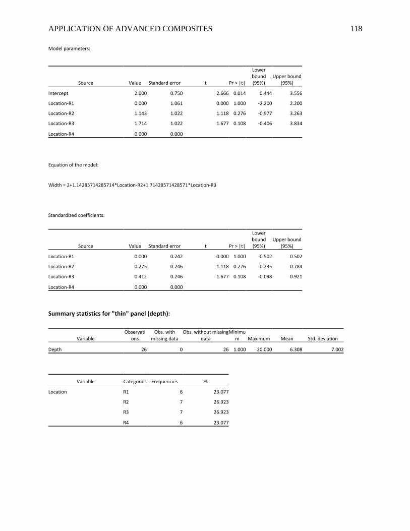
APPLICATION OF ADVANCED COMPOSITES 118
Model parameters:
Source Value Standard error t Pr > |t|
Lower bound (95%)
Upper bound (95%)
Intercept 2.000 0.750 2.666 0.014 0.444 3.556
Location-R1 0.000 1.061 0.000 1.000 -2.200 2.200
Location-R2 1.143 1.022 1.118 0.276 -0.977 3.263
Location-R3 1.714 1.022 1.677 0.108 -0.406 3.834
Location-R4 0.000 0.000
Equation of the model:
Width = 2+1.14285714285714*Location-R2+1.71428571428571*Location-R3
Standardized coefficients:
Source Value Standard error t Pr > |t|
Lower bound (95%)
Upper bound (95%)
Location-R1 0.000 0.242 0.000 1.000 -0.502 0.502
Location-R2 0.275 0.246 1.118 0.276 -0.235 0.784
Location-R3 0.412 0.246 1.677 0.108 -0.098 0.921
Location-R4 0.000 0.000
Summary statistics for "thin" panel (depth):
Variable Observati
ons Obs. with
missing data Obs. without missing
data Minimu
m Maximum Mean Std. deviation
Depth 26 0 26 1.000 20.000 6.308 7.002
Variable Categories Frequencies %
Location R1 6 23.077
R2 7 26.923
R3 7 26.923
R4 6 23.077
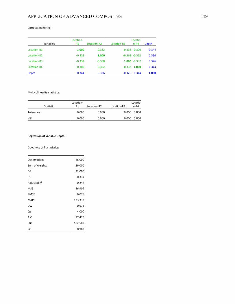
APPLICATION OF ADVANCED COMPOSITES 119
Correlation matrix:
Variables Location-
R1 Location-R2 Location-R3 Locatio
n-R4 Depth
Location-R1 1.000 -0.332 -0.332 -0.300 -0.344
Location-R2 -0.332 1.000 -0.368 -0.332 0.326
Location-R3 -0.332 -0.368 1.000 -0.332 0.326
Location-R4 -0.300 -0.332 -0.332 1.000 -0.344
Depth -0.344 0.326 0.326 -0.344 1.000
Multicolinearity statistics:
Statistic Location-
R1 Location-R2 Location-R3 Locatio
n-R4
Tolerance 0.000 0.000 0.000 0.000
VIF 0.000 0.000 0.000 0.000
Regression of variable Depth:
Goodness of fit statistics:
Observations 26.000
Sum of weights 26.000
DF 22.000
R² 0.337
Adjusted R² 0.247
MSE 36.909
RMSE 6.075
MAPE 133.333
DW 0.973
Cp 4.000
AIC 97.476
SBC 102.509
PC 0.903
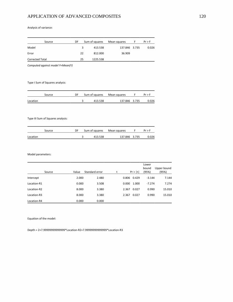
APPLICATION OF ADVANCED COMPOSITES 120
Analysis of variance:
Source DF Sum of squares Mean squares F Pr > F
Model 3 413.538 137.846 3.735 0.026
Error 22 812.000 36.909
Corrected Total 25 1225.538
Computed against model Y=Mean(Y)
Type I Sum of Squares analysis:
Source DF Sum of squares Mean squares F Pr > F
Location 3 413.538 137.846 3.735 0.026
Type III Sum of Squares analysis:
Source DF Sum of squares Mean squares F Pr > F
Location 3 413.538 137.846 3.735 0.026
Model parameters:
Source Value Standard error t Pr > |t|
Lower bound (95%)
Upper bound (95%)
Intercept 2.000 2.480 0.806 0.429 -3.144 7.144
Location-R1 0.000 3.508 0.000 1.000 -7.274 7.274
Location-R2 8.000 3.380 2.367 0.027 0.990 15.010
Location-R3 8.000 3.380 2.367 0.027 0.990 15.010
Location-R4 0.000 0.000
Equation of the model:
Depth = 2+7.99999999999999*Location-R2+7.99999999999999*Location-R3
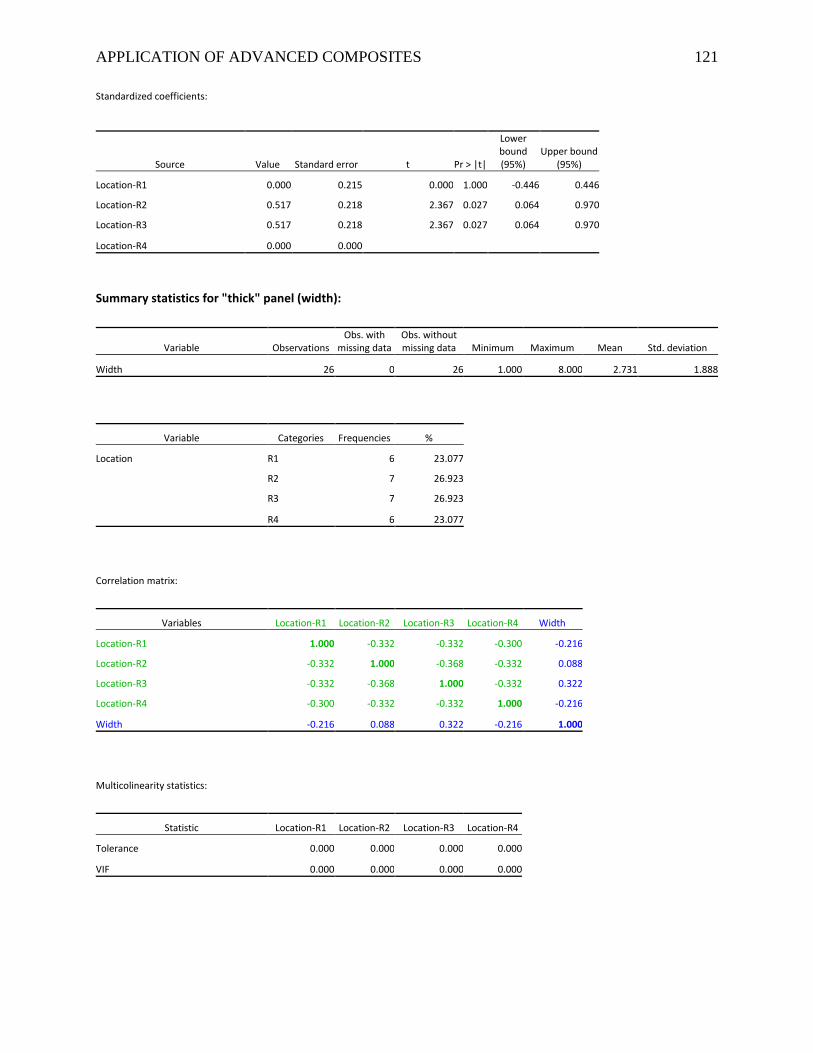
APPLICATION OF ADVANCED COMPOSITES 121
Standardized coefficients:
Source Value Standard error t Pr > |t|
Lower bound (95%)
Upper bound (95%)
Location-R1 0.000 0.215 0.000 1.000 -0.446 0.446
Location-R2 0.517 0.218 2.367 0.027 0.064 0.970
Location-R3 0.517 0.218 2.367 0.027 0.064 0.970
Location-R4 0.000 0.000
Summary statistics for "thick" panel (width):
Variable Observations Obs. with
missing data Obs. without missing data Minimum Maximum Mean Std. deviation
Width 26 0 26 1.000 8.000 2.731 1.888
Variable Categories Frequencies %
Location R1 6 23.077
R2 7 26.923
R3 7 26.923
R4 6 23.077
Correlation matrix:
Variables Location-R1 Location-R2 Location-R3 Location-R4 Width
Location-R1 1.000 -0.332 -0.332 -0.300 -0.216
Location-R2 -0.332 1.000 -0.368 -0.332 0.088
Location-R3 -0.332 -0.368 1.000 -0.332 0.322
Location-R4 -0.300 -0.332 -0.332 1.000 -0.216
Width -0.216 0.088 0.322 -0.216 1.000
Multicolinearity statistics:
Statistic Location-R1 Location-R2 Location-R3 Location-R4
Tolerance 0.000 0.000 0.000 0.000
VIF 0.000 0.000 0.000 0.000
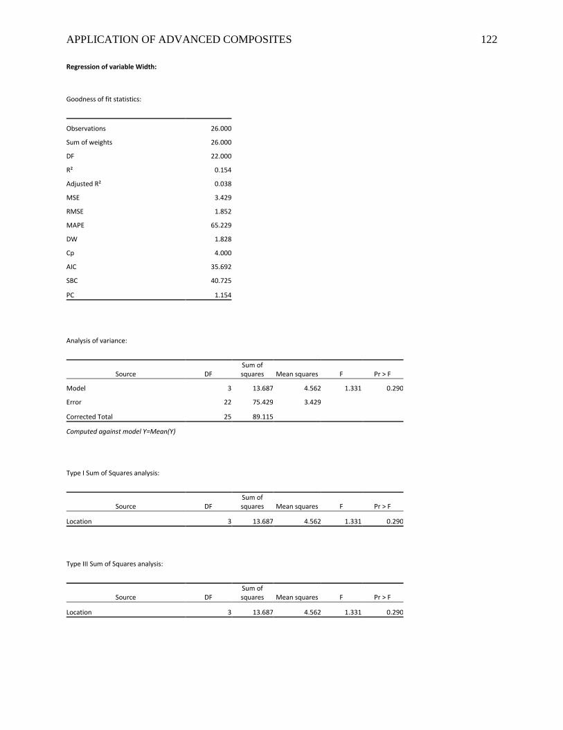
APPLICATION OF ADVANCED COMPOSITES 122
Regression of variable Width:
Goodness of fit statistics:
Observations 26.000
Sum of weights 26.000
DF 22.000
R² 0.154
Adjusted R² 0.038
MSE 3.429
RMSE 1.852
MAPE 65.229
DW 1.828
Cp 4.000
AIC 35.692
SBC 40.725
PC 1.154
Analysis of variance:
Source DF Sum of squares Mean squares F Pr > F
Model 3 13.687 4.562 1.331 0.290
Error 22 75.429 3.429
Corrected Total 25 89.115
Computed against model Y=Mean(Y)
Type I Sum of Squares analysis:
Source DF Sum of squares Mean squares F Pr > F
Location 3 13.687 4.562 1.331 0.290
Type III Sum of Squares analysis:
Source DF Sum of squares Mean squares F Pr > F
Location 3 13.687 4.562 1.331 0.290
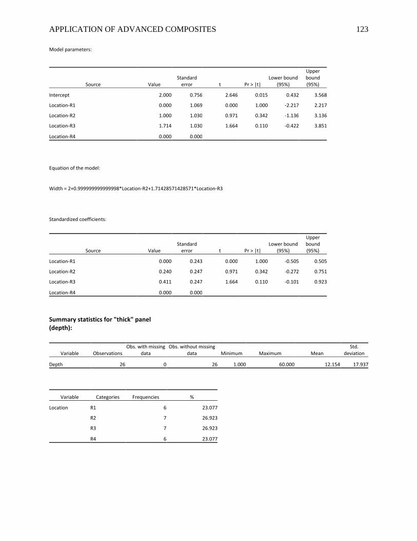
APPLICATION OF ADVANCED COMPOSITES 123
Model parameters:
Source Value Standard
error t Pr > |t| Lower bound
(95%)
Upper bound (95%)
Intercept 2.000 0.756 2.646 0.015 0.432 3.568
Location-R1 0.000 1.069 0.000 1.000 -2.217 2.217
Location-R2 1.000 1.030 0.971 0.342 -1.136 3.136
Location-R3 1.714 1.030 1.664 0.110 -0.422 3.851
Location-R4 0.000 0.000
Equation of the model:
Width = 2+0.999999999999998*Location-R2+1.71428571428571*Location-R3
Standardized coefficients:
Source Value Standard
error t Pr > |t| Lower bound
(95%)
Upper bound (95%)
Location-R1 0.000 0.243 0.000 1.000 -0.505 0.505
Location-R2 0.240 0.247 0.971 0.342 -0.272 0.751
Location-R3 0.411 0.247 1.664 0.110 -0.101 0.923
Location-R4 0.000 0.000
Summary statistics for "thick" panel (depth):
Variable Observations Obs. with missing
data Obs. without missing
data Minimum Maximum Mean Std.
deviation
Depth 26 0 26 1.000 60.000 12.154 17.937
Variable Categories Frequencies %
Location R1 6 23.077
R2 7 26.923
R3 7 26.923
R4 6 23.077
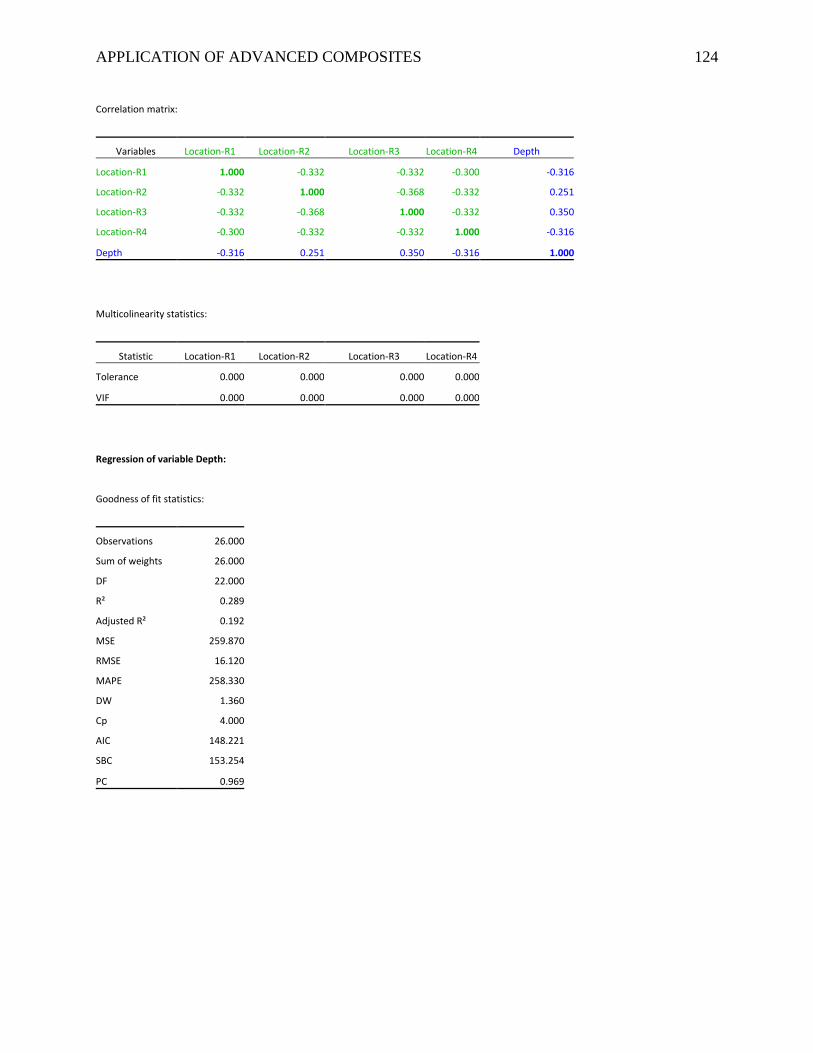
APPLICATION OF ADVANCED COMPOSITES 124
Correlation matrix:
Variables Location-R1 Location-R2 Location-R3 Location-R4 Depth
Location-R1 1.000 -0.332 -0.332 -0.300 -0.316
Location-R2 -0.332 1.000 -0.368 -0.332 0.251
Location-R3 -0.332 -0.368 1.000 -0.332 0.350
Location-R4 -0.300 -0.332 -0.332 1.000 -0.316
Depth -0.316 0.251 0.350 -0.316 1.000
Multicolinearity statistics:
Statistic Location-R1 Location-R2 Location-R3 Location-R4
Tolerance 0.000 0.000 0.000 0.000
VIF 0.000 0.000 0.000 0.000
Regression of variable Depth:
Goodness of fit statistics:
Observations 26.000
Sum of weights 26.000
DF 22.000
R² 0.289
Adjusted R² 0.192
MSE 259.870
RMSE 16.120
MAPE 258.330
DW 1.360
Cp 4.000
AIC 148.221
SBC 153.254
PC 0.969
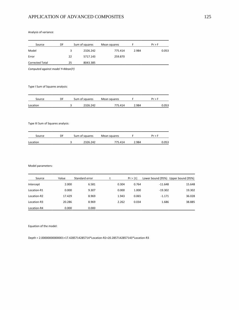
APPLICATION OF ADVANCED COMPOSITES 125
Analysis of variance:
Source DF Sum of squares Mean squares F Pr > F
Model 3 2326.242 775.414 2.984 0.053
Error 22 5717.143 259.870
Corrected Total 25 8043.385
Computed against model Y=Mean(Y)
Type I Sum of Squares analysis:
Source DF Sum of squares Mean squares F Pr > F
Location 3 2326.242 775.414 2.984 0.053
Type III Sum of Squares analysis:
Source DF Sum of squares Mean squares F Pr > F
Location 3 2326.242 775.414 2.984 0.053
Model parameters:
Source Value Standard error t Pr > |t| Lower bound (95%) Upper bound (95%)
Intercept 2.000 6.581 0.304 0.764 -11.648 15.648
Location-R1 0.000 9.307 0.000 1.000 -19.302 19.302
Location-R2 17.429 8.969 1.943 0.065 -1.171 36.028
Location-R3 20.286 8.969 2.262 0.034 1.686 38.885
Location-R4 0.000 0.000
Equation of the model:
Depth = 2.00000000000001+17.4285714285714*Location-R2+20.2857142857143*Location-R3
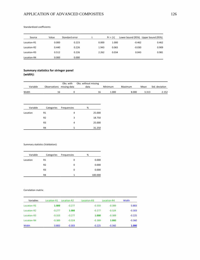
APPLICATION OF ADVANCED COMPOSITES 126
Standardized coefficients:
Source Value Standard error t Pr > |t| Lower bound (95%) Upper bound (95%)
Location-R1 0.000 0.223 0.000 1.000 -0.462 0.462
Location-R2 0.440 0.226 1.943 0.065 -0.030 0.909
Location-R3 0.512 0.226 2.262 0.034 0.043 0.981
Location-R4 0.000 0.000
Summary statistics for stringer panel (width):
Variable Observations Obs. with
missing data Obs. without missing
data Minimum Maximum Mean Std. deviation
Width 16 0 16 1.000 8.000 3.313 2.152
Variable Categories Frequencies %
Location R1 4 25.000
R2 3 18.750
R3 4 25.000
R4 5 31.250
Summary statistics (Validation):
Variable Categories Frequencies %
Location R1 0 0.000
R2 0 0.000
R3 0 0.000
R4 1 100.000
Correlation matrix:
Variables Location-R1 Location-R2 Location-R3 Location-R4 Width
Location-R1 1.000 -0.277 -0.333 -0.389 0.883
Location-R2 -0.277 1.000 -0.277 -0.324 -0.303
Location-R3 -0.333 -0.277 1.000 -0.389 -0.225
Location-R4 -0.389 -0.324 -0.389 1.000 -0.360
Width 0.883 -0.303 -0.225 -0.360 1.000
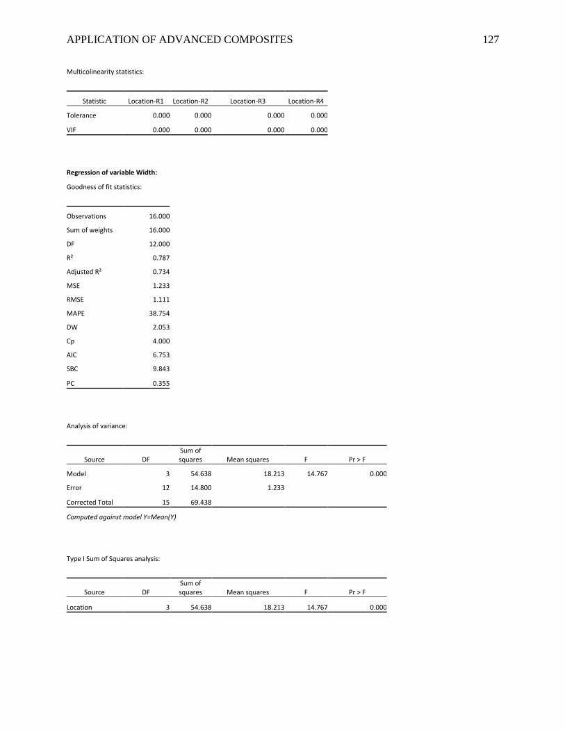
APPLICATION OF ADVANCED COMPOSITES 127
Multicolinearity statistics:
Statistic Location-R1 Location-R2 Location-R3 Location-R4
Tolerance 0.000 0.000 0.000 0.000
VIF 0.000 0.000 0.000 0.000
Regression of variable Width:
Goodness of fit statistics:
Observations 16.000
Sum of weights 16.000
DF 12.000
R² 0.787
Adjusted R² 0.734
MSE 1.233
RMSE 1.111
MAPE 38.754
DW 2.053
Cp 4.000
AIC 6.753
SBC 9.843
PC 0.355
Analysis of variance:
Source DF Sum of squares Mean squares F Pr > F
Model 3 54.638 18.213 14.767 0.000
Error 12 14.800 1.233
Corrected Total 15 69.438
Computed against model Y=Mean(Y)
Type I Sum of Squares analysis:
Source DF Sum of squares Mean squares F Pr > F
Location 3 54.638 18.213 14.767 0.000
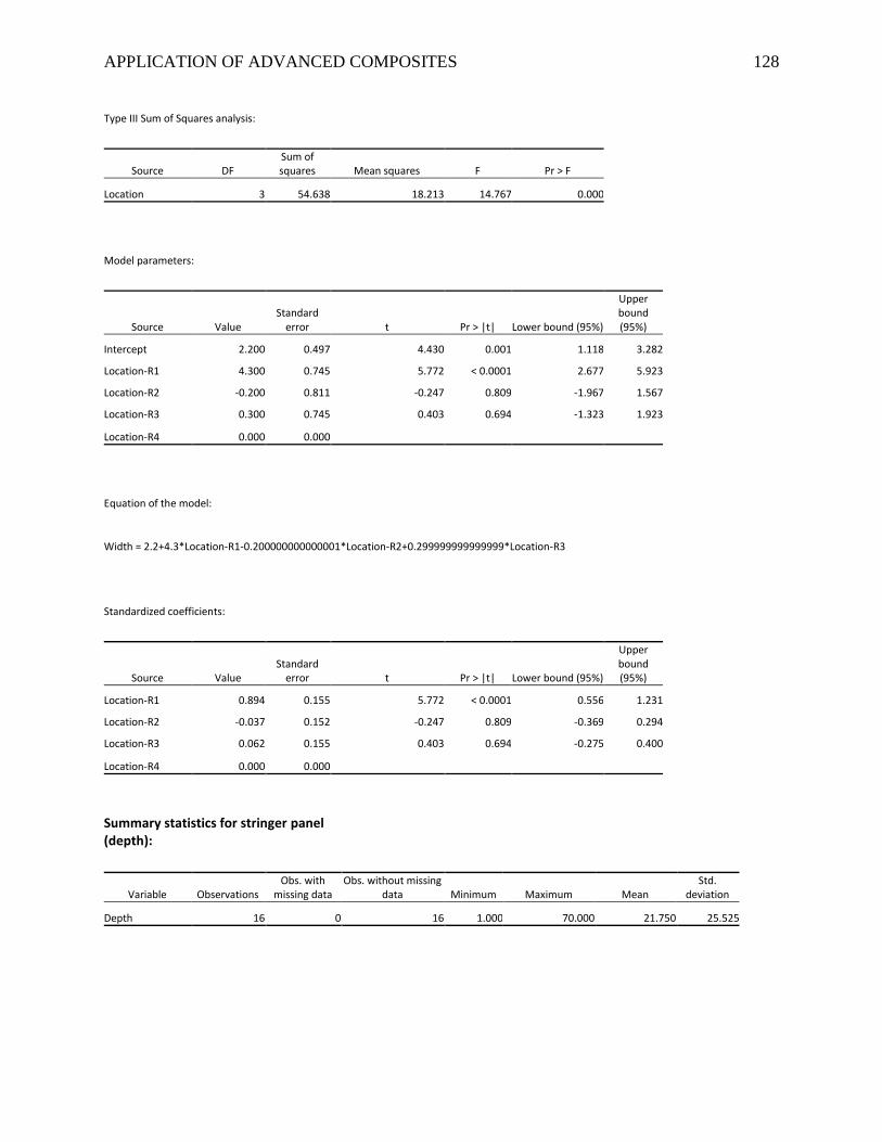
APPLICATION OF ADVANCED COMPOSITES 128
Type III Sum of Squares analysis:
Source DF Sum of squares Mean squares F Pr > F
Location 3 54.638 18.213 14.767 0.000
Model parameters:
Source Value Standard
error t Pr > |t| Lower bound (95%)
Upper bound (95%)
Intercept 2.200 0.497 4.430 0.001 1.118 3.282
Location-R1 4.300 0.745 5.772 < 0.0001 2.677 5.923
Location-R2 -0.200 0.811 -0.247 0.809 -1.967 1.567
Location-R3 0.300 0.745 0.403 0.694 -1.323 1.923
Location-R4 0.000 0.000
Equation of the model:
Width = 2.2+4.3*Location-R1-0.200000000000001*Location-R2+0.299999999999999*Location-R3
Standardized coefficients:
Source Value Standard
error t Pr > |t| Lower bound (95%)
Upper bound (95%)
Location-R1 0.894 0.155 5.772 < 0.0001 0.556 1.231
Location-R2 -0.037 0.152 -0.247 0.809 -0.369 0.294
Location-R3 0.062 0.155 0.403 0.694 -0.275 0.400
Location-R4 0.000 0.000
Summary statistics for stringer panel (depth):
Variable Observations Obs. with
missing data Obs. without missing
data Minimum Maximum Mean Std.
deviation
Depth 16 0 16 1.000 70.000 21.750 25.525
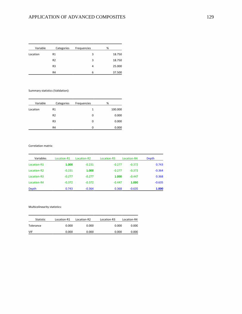
APPLICATION OF ADVANCED COMPOSITES 129
Variable Categories Frequencies %
Location R1 3 18.750
R2 3 18.750
R3 4 25.000
R4 6 37.500
Summary statistics (Validation):
Variable Categories Frequencies %
Location R1 1 100.000
R2 0 0.000
R3 0 0.000
R4 0 0.000
Correlation matrix:
Variables Location-R1 Location-R2 Location-R3 Location-R4 Depth
Location-R1 1.000 -0.231 -0.277 -0.372 0.743
Location-R2 -0.231 1.000 -0.277 -0.372 -0.364
Location-R3 -0.277 -0.277 1.000 -0.447 0.368
Location-R4 -0.372 -0.372 -0.447 1.000 -0.635
Depth 0.743 -0.364 0.368 -0.635 1.000
Multicolinearity statistics:
Statistic Location-R1 Location-R2 Location-R3 Location-R4
Tolerance 0.000 0.000 0.000 0.000
VIF 0.000 0.000 0.000 0.000
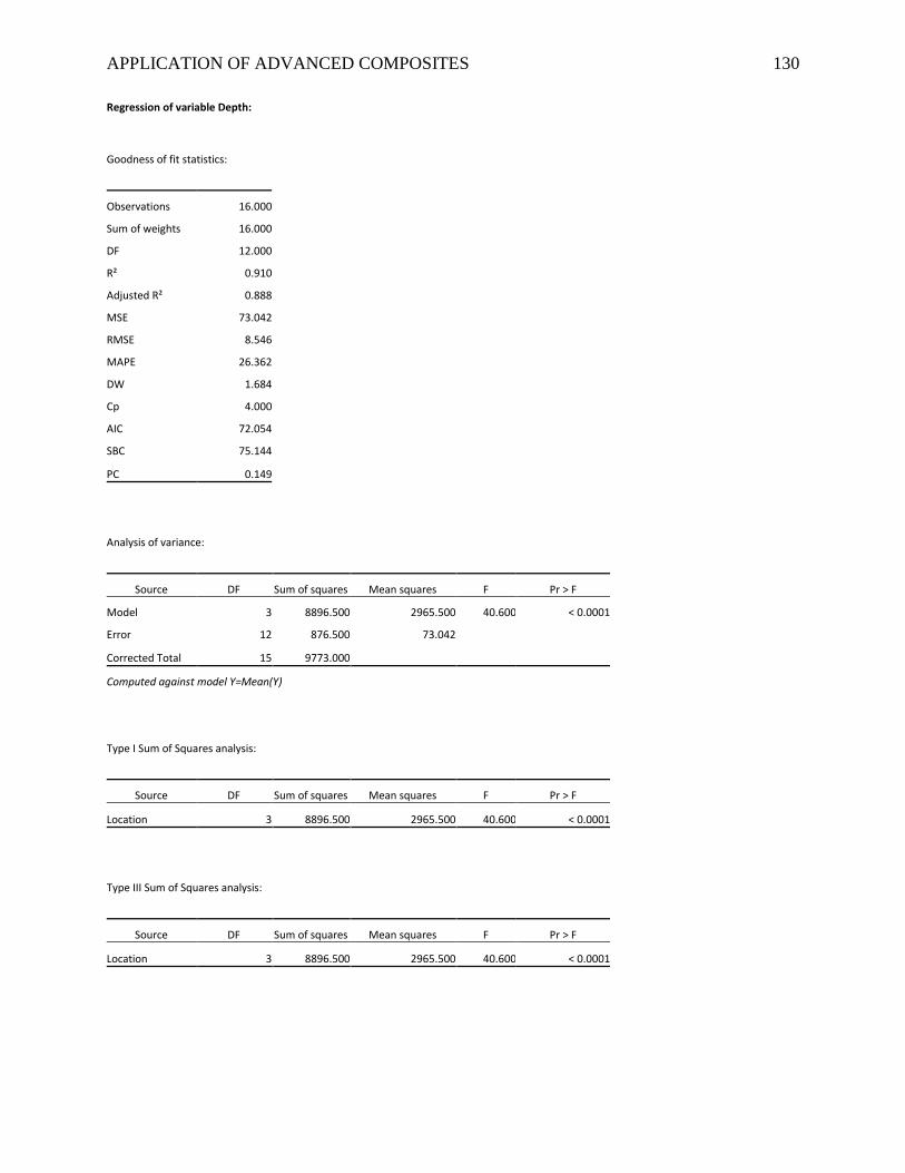
APPLICATION OF ADVANCED COMPOSITES 130
Regression of variable Depth:
Goodness of fit statistics:
Observations 16.000
Sum of weights 16.000
DF 12.000
R² 0.910
Adjusted R² 0.888
MSE 73.042
RMSE 8.546
MAPE 26.362
DW 1.684
Cp 4.000
AIC 72.054
SBC 75.144
PC 0.149
Analysis of variance:
Source DF Sum of squares Mean squares F Pr > F
Model 3 8896.500 2965.500 40.600 < 0.0001
Error 12 876.500 73.042
Corrected Total 15 9773.000
Computed against model Y=Mean(Y)
Type I Sum of Squares analysis:
Source DF Sum of squares Mean squares F Pr > F
Location 3 8896.500 2965.500 40.600 < 0.0001
Type III Sum of Squares analysis:
Source DF Sum of squares Mean squares F Pr > F
Location 3 8896.500 2965.500 40.600 < 0.0001
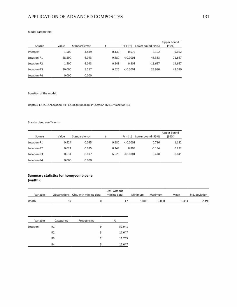
APPLICATION OF ADVANCED COMPOSITES 131
Model parameters:
Source Value Standard error t Pr > |t| Lower bound (95%) Upper bound
(95%)
Intercept 1.500 3.489 0.430 0.675 -6.102 9.102
Location-R1 58.500 6.043 9.680 < 0.0001 45.333 71.667
Location-R2 1.500 6.043 0.248 0.808 -11.667 14.667
Location-R3 36.000 5.517 6.526 < 0.0001 23.980 48.020
Location-R4 0.000 0.000
Equation of the model:
Depth = 1.5+58.5*Location-R1+1.50000000000001*Location-R2+36*Location-R3
Standardized coefficients:
Source Value Standard error t Pr > |t| Lower bound (95%) Upper bound
(95%)
Location-R1 0.924 0.095 9.680 < 0.0001 0.716 1.132
Location-R2 0.024 0.095 0.248 0.808 -0.184 0.232
Location-R3 0.631 0.097 6.526 < 0.0001 0.420 0.841
Location-R4 0.000 0.000
Summary statistics for honeycomb panel (width):
Variable Observations Obs. with missing data Obs. without missing data Minimum Maximum Mean Std. deviation
Width 17 0 17 1.000 9.000 3.353 2.499
Variable Categories Frequencies %
Location R1 9 52.941
R2 3 17.647
R3 2 11.765
R4 3 17.647
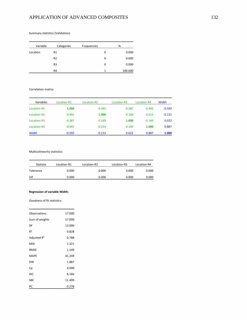
APPLICATION OF ADVANCED COMPOSITES 132
Summary statistics (Validation):
Variable Categories Frequencies %
Location R1 0 0.000
R2 0 0.000
R3 0 0.000
R4 1 100.000
Correlation matrix:
Variables Location-R1 Location-R2 Location-R3 Location-R4 Width
Location-R1 1.000 -0.491 -0.387 -0.491 -0.592
Location-R2 -0.491 1.000 -0.169 -0.214 -0.131
Location-R3 -0.387 -0.169 1.000 -0.169 0.022
Location-R4 -0.491 -0.214 -0.169 1.000 0.887
Width -0.592 -0.131 0.022 0.887 1.000
Multicolinearity statistics:
Statistic Location-R1 Location-R2 Location-R3 Location-R4
Tolerance 0.000 0.000 0.000 0.000
VIF 0.000 0.000 0.000 0.000
Regression of variable Width:
Goodness of fit statistics:
Observations 17.000
Sum of weights 17.000
DF 13.000
R² 0.828
Adjusted R² 0.788
MSE 1.321
RMSE 1.149
MAPE 41.249
DW 1.887
Cp 4.000
AIC 8.166
SBC 11.499
PC 0.278
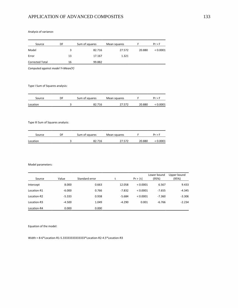
APPLICATION OF ADVANCED COMPOSITES 133
Analysis of variance:
Source DF Sum of squares Mean squares F Pr > F
Model 3 82.716 27.572 20.880 < 0.0001
Error 13 17.167 1.321
Corrected Total 16 99.882
Computed against model Y=Mean(Y)
Type I Sum of Squares analysis:
Source DF Sum of squares Mean squares F Pr > F
Location 3 82.716 27.572 20.880 < 0.0001
Type III Sum of Squares analysis:
Source DF Sum of squares Mean squares F Pr > F
Location 3 82.716 27.572 20.880 < 0.0001
Model parameters:
Source Value Standard error t Pr > |t| Lower bound
(95%) Upper bound
(95%)
Intercept 8.000 0.663 12.058 < 0.0001 6.567 9.433
Location-R1 -6.000 0.766 -7.832 < 0.0001 -7.655 -4.345
Location-R2 -5.333 0.938 -5.684 < 0.0001 -7.360 -3.306
Location-R3 -4.500 1.049 -4.290 0.001 -6.766 -2.234
Location-R4 0.000 0.000
Equation of the model:
Width = 8-6*Location-R1-5.33333333333333*Location-R2-4.5*Location-R3
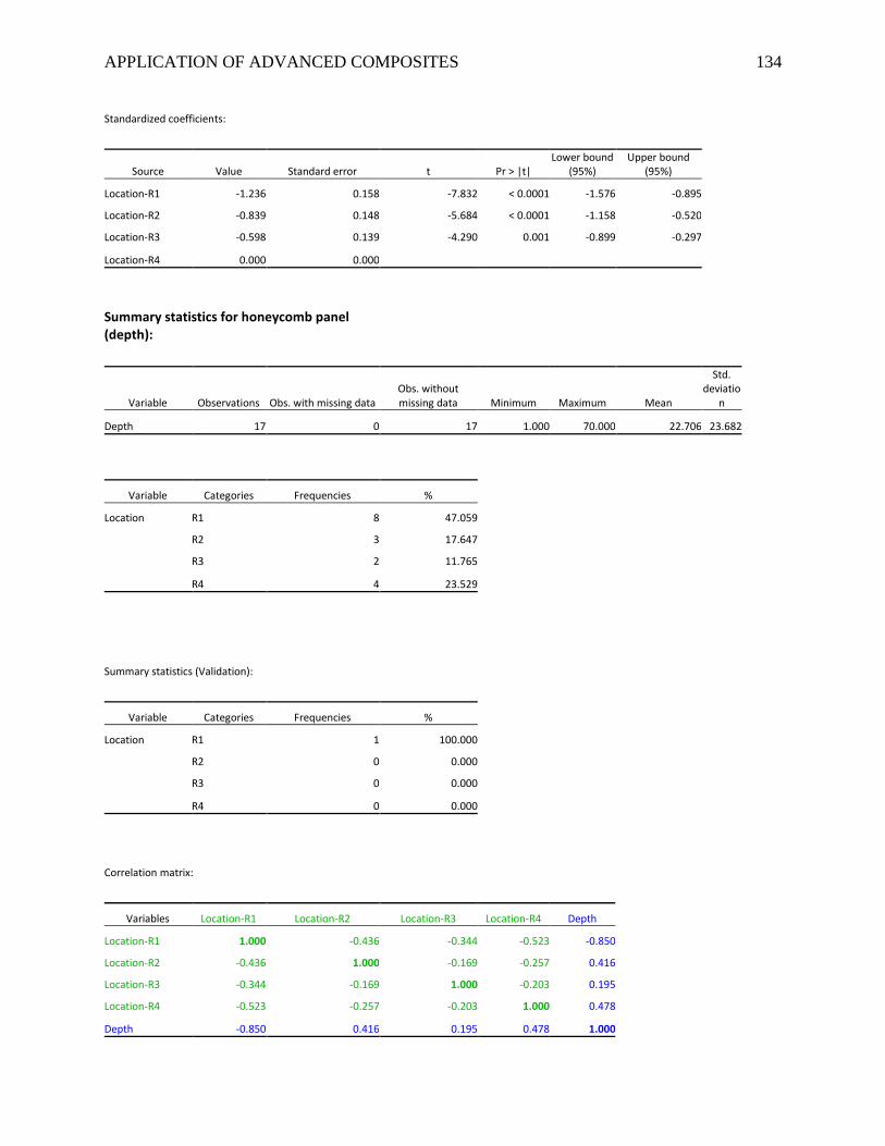
APPLICATION OF ADVANCED COMPOSITES 134
Standardized coefficients:
Source Value Standard error t Pr > |t| Lower bound
(95%) Upper bound
(95%)
Location-R1 -1.236 0.158 -7.832 < 0.0001 -1.576 -0.895
Location-R2 -0.839 0.148 -5.684 < 0.0001 -1.158 -0.520
Location-R3 -0.598 0.139 -4.290 0.001 -0.899 -0.297
Location-R4 0.000 0.000
Summary statistics for honeycomb panel (depth):
Variable Observations Obs. with missing data Obs. without missing data Minimum Maximum Mean
Std. deviatio
n
Depth 17 0 17 1.000 70.000 22.706 23.682
Variable Categories Frequencies %
Location R1 8 47.059
R2 3 17.647
R3 2 11.765
R4 4 23.529
Summary statistics (Validation):
Variable Categories Frequencies %
Location R1 1 100.000
R2 0 0.000
R3 0 0.000
R4 0 0.000
Correlation matrix:
Variables Location-R1 Location-R2 Location-R3 Location-R4 Depth
Location-R1 1.000 -0.436 -0.344 -0.523 -0.850
Location-R2 -0.436 1.000 -0.169 -0.257 0.416
Location-R3 -0.344 -0.169 1.000 -0.203 0.195
Location-R4 -0.523 -0.257 -0.203 1.000 0.478
Depth -0.850 0.416 0.195 0.478 1.000
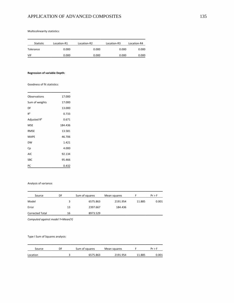
APPLICATION OF ADVANCED COMPOSITES 135
Multicolinearity statistics:
Statistic Location-R1 Location-R2 Location-R3 Location-R4
Tolerance 0.000 0.000 0.000 0.000
VIF 0.000 0.000 0.000 0.000
Regression of variable Depth:
Goodness of fit statistics:
Observations 17.000
Sum of weights 17.000
DF 13.000
R² 0.733
Adjusted R² 0.671
MSE 184.436
RMSE 13.581
MAPE 46.706
DW 1.421
Cp 4.000
AIC 92.134
SBC 95.466
PC 0.432
Analysis of variance:
Source DF Sum of squares Mean squares F Pr > F
Model 3 6575.863 2191.954 11.885 0.001
Error 13 2397.667 184.436
Corrected Total 16 8973.529
Computed against model Y=Mean(Y)
Type I Sum of Squares analysis:
Source DF Sum of squares Mean squares F Pr > F
Location 3 6575.863 2191.954 11.885 0.001
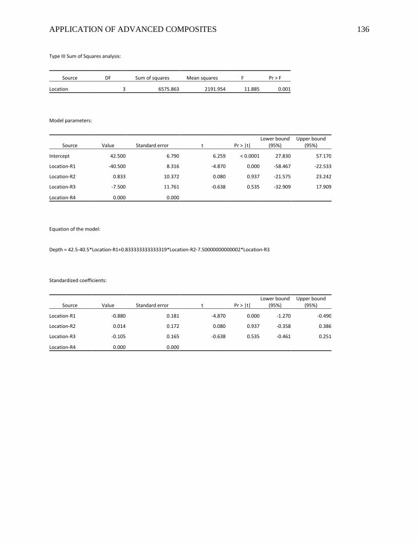
APPLICATION OF ADVANCED COMPOSITES 136
Type III Sum of Squares analysis:
Source DF Sum of squares Mean squares F Pr > F
Location 3 6575.863 2191.954 11.885 0.001
Model parameters:
Source Value Standard error t Pr > |t| Lower bound
(95%) Upper bound
(95%)
Intercept 42.500 6.790 6.259 < 0.0001 27.830 57.170
Location-R1 -40.500 8.316 -4.870 0.000 -58.467 -22.533
Location-R2 0.833 10.372 0.080 0.937 -21.575 23.242
Location-R3 -7.500 11.761 -0.638 0.535 -32.909 17.909
Location-R4 0.000 0.000
Equation of the model:
Depth = 42.5-40.5*Location-R1+0.833333333333319*Location-R2-7.50000000000002*Location-R3
Standardized coefficients:
Source Value Standard error t Pr > |t| Lower bound
(95%) Upper bound
(95%)
Location-R1 -0.880 0.181 -4.870 0.000 -1.270 -0.490
Location-R2 0.014 0.172 0.080 0.937 -0.358 0.386
Location-R3 -0.105 0.165 -0.638 0.535 -0.461 0.251
Location-R4 0.000 0.000


![Advanced Composites - MEAN] Laboratory](https://img.pdfslide.us/doc/110x75/61bd0f4161276e740b0eefd9/advanced-composites-mean-laboratory.jpg)