Embed Size (px)
Citation preview

The Anatomy of a Wind Plant
GADS Wind Training Module 02March 2019 – Final
RELIABILITY | ACCOUNTABILITY2
• The following will be reviewed in this module: Components of a GADS Wind Plant Plant Definition Plant Boundaries Gen-Tie and Plant Boundaries The relationship between Plant, Groups and Sub-Groups Simple plant example Complex plant example Energy distribution Turbine replacement example Repower or replacement turbines examples Plant with multiple revenue meters Multiple plants sharing a common substation and revenue meter
Content
RELIABILITY | ACCOUNTABILITY3
Components of a GADS Wind Plant
Plant B
oundary
Plant Boundary
Plant B
oundary
Plant BoundaryPlant Boundary
SubstationPlant A
Low side
Transformer
High side
Grou
p 1
Sub-Group 1A
Off-Taker
RevenueMeter
Sub-Group 1B
Group 2
Sub-Group 2A Sub-Group 2B Sub-Group 2C
Grou
p 3
Sub-Group 3A
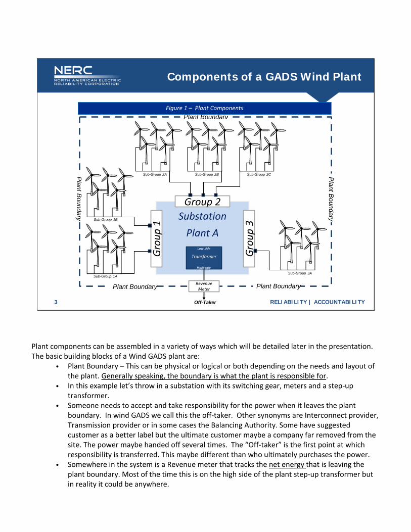
Figure 1 – Plant Components
Plant components can be assembled in a variety of ways which will be detailed later in the presentation. The basic building blocks of a Wind GADS plant are:
• Plant Boundary – This can be physical or logical or both depending on the needs and layout of the plant. Generally speaking, the boundary is what the plant is responsible for.
• In this example let’s throw in a substation with its switching gear, meters and a step-up transformer.
• Someone needs to accept and take responsibility for the power when it leaves the plant boundary. In wind GADS we call this the off-taker. Other synonyms are Interconnect provider, Transmission provider or in some cases the Balancing Authority. Some have suggested customer as a better label but the ultimate customer maybe a company far removed from the site. The power maybe handed off several times. The “Off-taker” is the first point at which responsibility is transferred. This maybe different than who ultimately purchases the power.
• Somewhere in the system is a Revenue meter that tracks the net energy that is leaving the plant boundary. Most of the time this is on the high side of the plant step-up transformer but in reality it could be anywhere.
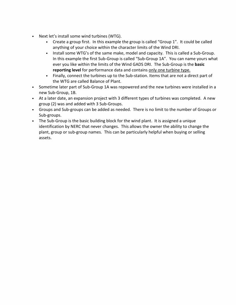
• Next let’s install some wind turbines (WTG). • Create a group first. In this example the group is called “Group 1”. It could be called
anything of your choice within the character limits of the Wind DRI. • Install some WTG’s of the same make, model and capacity. This is called a Sub-Group.
In this example the first Sub-Group is called “Sub-Group 1A”. You can name yours what ever you like within the limits of the Wind GADS DRI. The Sub-Group is the basic reporting level for performance data and contains only one turbine type.
• Finally, connect the turbines up to the Sub-station. Items that are not a direct part of the WTG are called Balance of Plant.
• Sometime later part of Sub-Group 1A was repowered and the new turbines were installed in a new Sub-Group, 1B.
• At a later date, an expansion project with 3 different types of turbines was completed. A new group (2) was and added with 3 Sub-Groups.
• Groups and Sub-groups can be added as needed. There is no limit to the number of Groups or Sub-groups.
• The Sub-Group is the basic building block for the wind plant. It is assigned a unique identification by NERC that never changes. This allows the owner the ability to change the plant, group or sub-group names. This can be particularly helpful when buying or selling assets.
RELIABILITY | ACCOUNTABILITY4
Plant Definition
The original intent for a Plant was to define wind turbines (WTG) located in a close geographical region, managed by a single manager and operating out of a common O&M building. Plant capacity also defines reporting requirements. Plants will have many of the following characteristics:
1. One geographical area. Not spread across state boundaries2. Managed by a single plant manager3. Crews meet daily in a common O&M building4. Common inventory storage area, common trucks and crews5. All the Sub-Groups have the same NERC Compliance Registry Number (Utility ID)6. Loan, insurance, and interconnect agreements treat it as a single plant.7. Treated as a single plant when reporting annually to FERC (EIA)8. The Off-taker (interconnect or balancing authority) provides dispatch to a single plant9. How was the project published in the annual and quarterly trade reports?
10. Local network for SCADA, 3rd party communications between groups not required11. Travel between WTG’s and O&M is usually measured in minutes and not hours or days12. Treated as a single plant within the parent utility13. OSHA statistics are tracked as a single company14. Common safety plan15. Hazardous waste handled as a single entity
• A plant may not have all of the above characteristics but will have many of the above. There are exceptions to any one of the above
• The overall guide is how the plant is managed. • Plant Managers are responsible for the overall safety of the Plant, hiring, discipline, Plant performance
and etc. The Plant Manager is the individual that OSHA would go to during a surprise inspection. A lead technician, in charge of a section of the plant, should not be confused with the Plant Manager.
RELIABILITY | ACCOUNTABILITY5
Plant Boundaries
The GADS Wind DRI lists several examples for boundary definitions:1. The preferred plant boundary at the revenue meter is usually at the high-voltage
terminals of the generator step-up (GSU) transformer and the station service transformers (Figure 1).
2. In cases of multiple sub-groups, the plant boundary will be at the metering of the low side of the substation transformer (load) side of the generator voltage circuit breakers
3. Any equipment boundary that is reasonable considering the design and configuration of the generating unit.
• The boundary can be both physical and logical. It is:o A circle around all the plant equipmento The border where someone else (off-taker) assumes responsibility for the power
generated. Usually there is a revenue meter at this point but not always.
• In any case, Plant Boundaries never extend beyond the revenue meter. Net metering is always at the revenue meter.
• Notice that the 3 definitions of a plant boundary are fairly loose. • You determine where your boundaries are but they should include all the equipment that the plant is
responsible for.
RELIABILITY | ACCOUNTABILITY6
Bulk Electrical System (BES)Plant Boundary
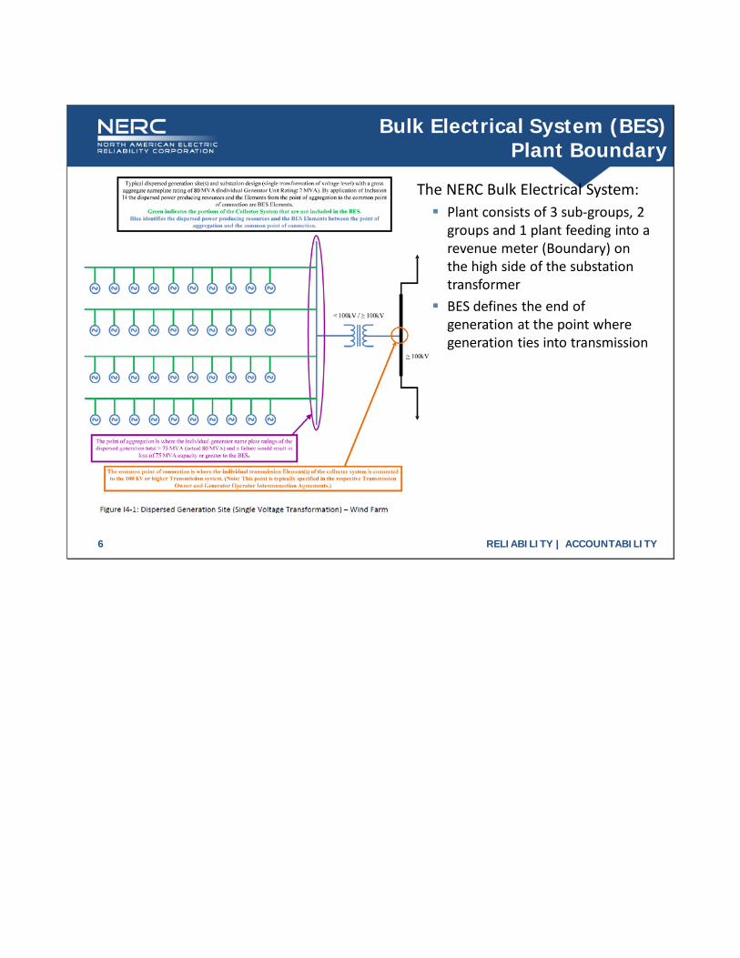
The NERC Bulk Electrical System: Plant consists of 3 sub-groups, 2
groups and 1 plant feeding into a revenue meter (Boundary) on the high side of the substation transformer
BES defines the end of generation at the point where generation ties into transmission
RELIABILITY | ACCOUNTABILITY7
Gen-Tie and Plant Boundaries
• Gen-Tie A transmission line connecting the plant to the distribution system. o At no point does the Plant Boundary extend beyond the revenue meter
• Concerns: Revenue metering maybe at the beginning or end of the Gen-Tie If the Revenue meter is at the end of the line, multiple plants could share a revenue
distribution scheme at the meter Gen-Ties are subject to third-party utilization Gen-Ties may be subject to TADS reporting depending on the voltage
• General guidelines for boundaries with Gen-Ties: Meter at Plant – Boundary at the meter Meter at far end of Gen-Tie:o It is the Plant’s responsibility to maintain Gen-Tie: Boundary at the meter. Code Gen-Tie
outages as Balance of Plant – Transmission (Gen-Tie)o Not the Plant’s responsibility to maintain the Gen-Tie – Boundary at the Plant end of the
Gen-Tie – Code Gen-Tie outages as External – Off-taker (OMC)
• Gen-Ties can be tricky when it comes to Plant Boundaries. Sometimes they can be several hundred miles long before reaching a distribution system.
• Sometimes the revenue meter is at the plant end of the Gen-Tie and other times it is at the far end. • The general rule is the boundary never extends beyond the Revenue Meter. • When the Revenue Meter is at the far end of the Gen-tie, the Plant Boundary may vary depending on
who is responsible for maintaining the equipment (Plant or someone else). That someone else could even be a different group within the same organization.
• Some of the issues with Gen-ties are: • Sometimes there are multiple plants (same or different companies) that share the Gen-tie. • It is possible for a 3rd party to force their way on to your line if they can determine that there is
additional capacity or are willing to pay for upgrades. • If the voltage is high enough the reporting rules may be different (TADS rules) and would not
be part of the GADS Wind DRI.

RELIABILITY | ACCOUNTABILITY8
The Relationship Between Plants, Groups and Sub-Groups
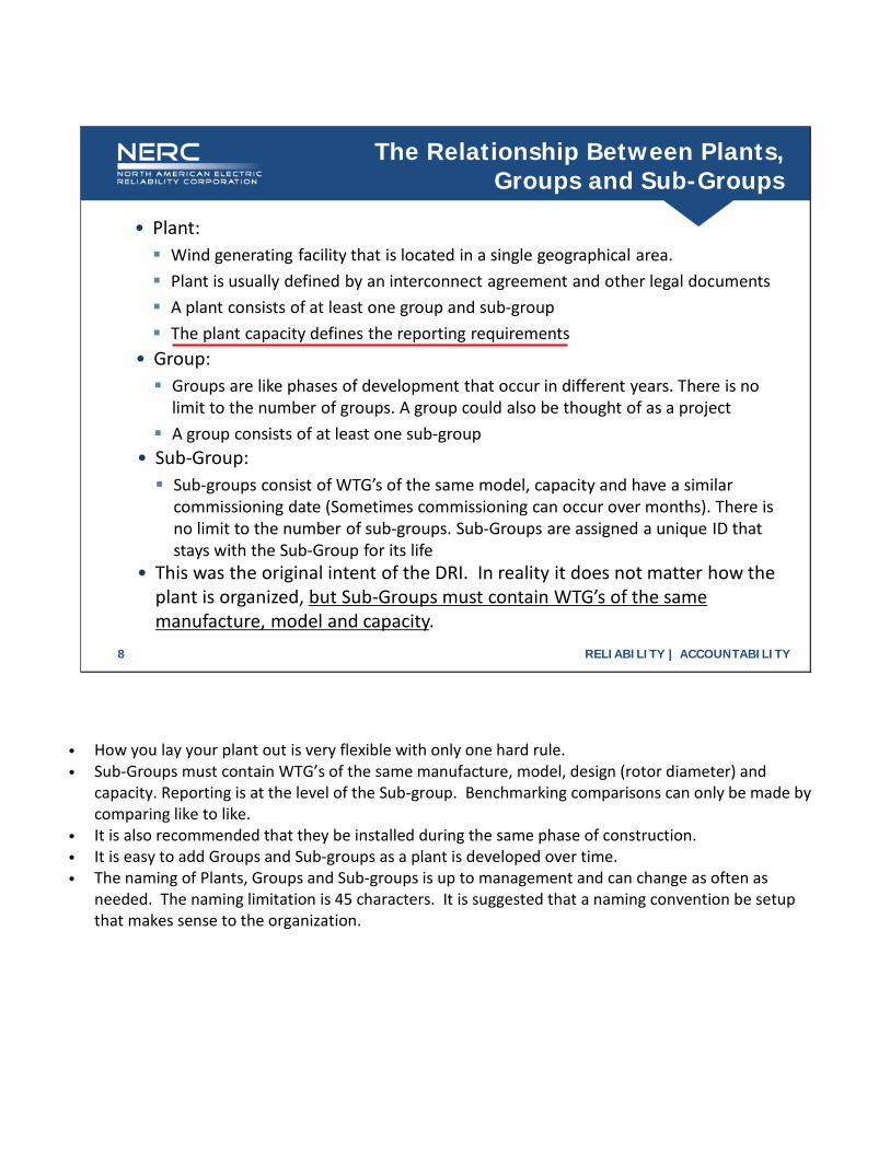
• Plant: Wind generating facility that is located in a single geographical area. Plant is usually defined by an interconnect agreement and other legal documents A plant consists of at least one group and sub-group The plant capacity defines the reporting requirements
• Group: Groups are like phases of development that occur in different years. There is no
limit to the number of groups. A group could also be thought of as a project A group consists of at least one sub-group
• Sub-Group: Sub-groups consist of WTG’s of the same model, capacity and have a similar
commissioning date (Sometimes commissioning can occur over months). There is no limit to the number of sub-groups. Sub-Groups are assigned a unique ID that stays with the Sub-Group for its life
• This was the original intent of the DRI. In reality it does not matter how the plant is organized, but Sub-Groups must contain WTG’s of the same manufacture, model and capacity.
• How you lay your plant out is very flexible with only one hard rule. • Sub-Groups must contain WTG’s of the same manufacture, model, design (rotor diameter) and
capacity. Reporting is at the level of the Sub-group. Benchmarking comparisons can only be made by comparing like to like.
• It is also recommended that they be installed during the same phase of construction. • It is easy to add Groups and Sub-groups as a plant is developed over time. • The naming of Plants, Groups and Sub-groups is up to management and can change as often as
needed. The naming limitation is 45 characters. It is suggested that a naming convention be setup that makes sense to the organization.
RELIABILITY | ACCOUNTABILITY9
Simple Plant Example
Switch YardPlant A
Group 1
Sub-Group 1A
Off-Taker
RevenueMeter
Plant B
oundary
Plant Boundary
Plant B
oundary
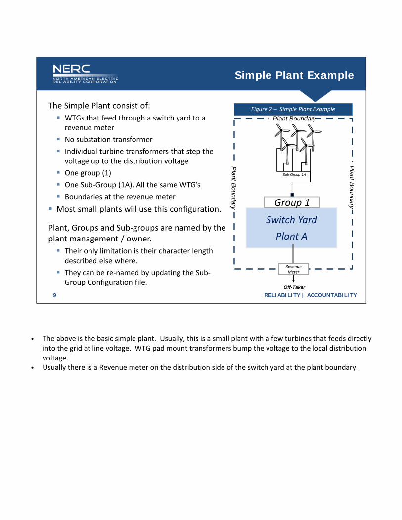
The Simple Plant consist of: WTGs that feed through a switch yard to a
revenue meter No substation transformer Individual turbine transformers that step the
voltage up to the distribution voltage One group (1) One Sub-Group (1A). All the same WTG’s Boundaries at the revenue meter
Most small plants will use this configuration.
Figure 2 – Simple Plant Example
Plant, Groups and Sub-groups are named by the plant management / owner. Their only limitation is their character length
described else where. They can be re-named by updating the Sub-
Group Configuration file.
• The above is the basic simple plant. Usually, this is a small plant with a few turbines that feeds directly into the grid at line voltage. WTG pad mount transformers bump the voltage to the local distribution voltage.
• Usually there is a Revenue meter on the distribution side of the switch yard at the plant boundary.
RELIABILITY | ACCOUNTABILITY10
Complex Plant Example
SubstationPlant A
Group 2
Grou
p 1Sub-Group 1A
Sub-Group 1B
Sub-Group 2A
Low side
Transformer
High side
Off-Taker
RevenueMeter
Plant B
oundary
Plant Boundary
Plant B
oundary
Plant Boundary
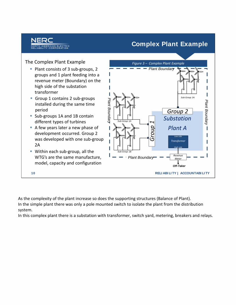
Figure 3 – Complex Plant ExampleThe Complex Plant Example Plant consists of 3 sub-groups, 2
groups and 1 plant feeding into a revenue meter (Boundary) on the high side of the substation transformer
Group 1 contains 2 sub-groups installed during the same time period
Sub-groups 1A and 1B contain different types of turbines
Within each sub-group, all the WTG’s are the same manufacture, model, capacity and configuration
A few years later a new phase of development occurred. Group 2 was developed with one sub-group 2A
As the complexity of the plant increase so does the supporting structures (Balance of Plant). In the simple plant there was only a pole mounted switch to isolate the plant from the distribution system. In this complex plant there is a substation with transformer, switch yard, metering, breakers and relays.
RELIABILITY | ACCOUNTABILITY11
Energy Distribution
With the Simple Plant, energy distribution is straight forward. All the energy from a single group feeds through a single revenue meter.
With the Complex Plant and the other examples, multiple sub-groups feed through a single revenue meter. The actual method that the plant uses to distribute the net energy from the revenue meter is up to plant management. Examples:
Meters on the low side of the substation transformer. This works if the sub-groups have separate feeders. Simply prorate the revenue net energy based on the feeder meters. The DRI does not require revenue quality meters. Monitoring the meters for variance will allow you to catch when metering discrepancies occur. Also, financial or partnership agreements may require revenue quality metering.
Distribute the revenue meter net energy based on the individual turbine production. The WTG meters may not be perfect but with enough turbines there will be a normal distribution of accuracy.
We are often asked about the accuracy required of various meters. • Nowhere in the DRI is there a requirement for revenue quality meters. Those requirements will
be found in your PPA’s, loan and partnership agreements. • One of the reasons for the 2005 commissioning date and 75 MW or larger requirement for
mandatory reporting was to eliminate most of the outdated and problematic equipment. • The author of this document reviewed data from a site installed in 1992 and found 2-4%
difference between the revenue meter and the sum of the turbine meters. This is what was expected for line loss and other parasitic loads.
RELIABILITY | ACCOUNTABILITY12
Energy Distribution (cont’d)
• Occasionally, complex feeders will be composed of multiple types of WTG’s. In this situation, identify sub-group generation is by using the WTG meters. This situation occurs by design, repower or replacement of failed turbines.
• Bottom line There are many ways to distribute the net energy at the revenue meter. Plant management must develop the best methods based on the available
equipment that meets the requirements of energy contracts, loan agreements and partnership documents.
RELIABILITY | ACCOUNTABILITY13
Single Turbine Replacement
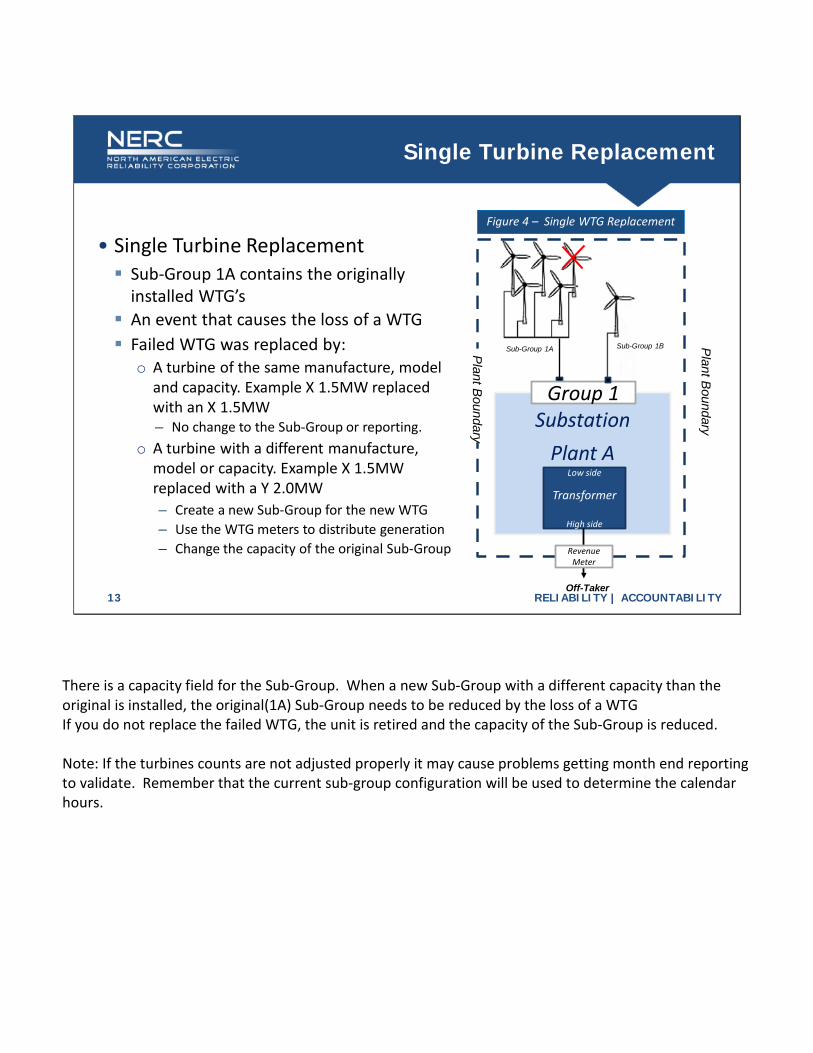
• Single Turbine Replacement Sub-Group 1A contains the originally
installed WTG’s
SubstationPlant A
Group 1
Sub-Group 1BSub-Group 1A
Low side
Transformer
High side
Off-Taker
RevenueMeter
Plant B
oundary
Plant B
oundary
Figure 4 – Single WTG Replacement
An event that causes the loss of a WTG Failed WTG was replaced by:
o A turbine of the same manufacture, model and capacity. Example X 1.5MW replaced with an X 1.5MW– No change to the Sub-Group or reporting.
o A turbine with a different manufacture, model or capacity. Example X 1.5MW replaced with a Y 2.0MW – Create a new Sub-Group for the new WTG– Use the WTG meters to distribute generation– Change the capacity of the original Sub-Group
There is a capacity field for the Sub-Group. When a new Sub-Group with a different capacity than the original is installed, the original(1A) Sub-Group needs to be reduced by the loss of a WTG If you do not replace the failed WTG, the unit is retired and the capacity of the Sub-Group is reduced. Note: If the turbines counts are not adjusted properly it may cause problems getting month end reporting to validate. Remember that the current sub-group configuration will be used to determine the calendar hours.
RELIABILITY | ACCOUNTABILITY14
Repower Older Turbines
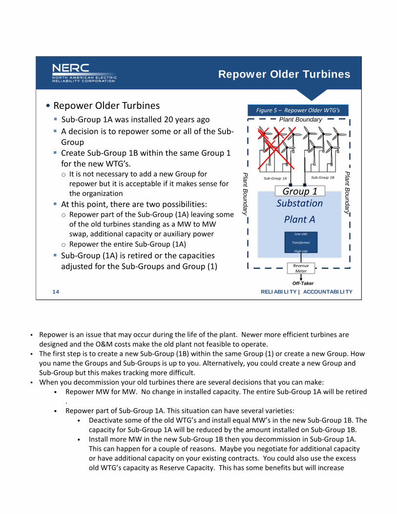
• Repower Older Turbines Sub-Group 1A was installed 20 years ago
SubstationPlant A
Group 1Sub-Group 1B
Low side
Transformer
High side
Off-Taker
Plant B
oundary
Plant B
oundary
Plant BoundaryFigure 5 – Repower Older WTG’s
Sub-Group 1A
RevenueMeter
A decision is to repower some or all of the Sub-Group
Create Sub-Group 1B within the same Group 1 for the new WTG’s. o It is not necessary to add a new Group for
repower but it is acceptable if it makes sense for the organization
At this point, there are two possibilities:o Repower part of the Sub-Group (1A) leaving some
of the old turbines standing as a MW to MW swap, additional capacity or auxiliary power
o Repower the entire Sub-Group (1A) Sub-Group (1A) is retired or the capacities
adjusted for the Sub-Groups and Group (1)
• Repower is an issue that may occur during the life of the plant. Newer more efficient turbines are designed and the O&M costs make the old plant not feasible to operate.
• The first step is to create a new Sub-Group (1B) within the same Group (1) or create a new Group. How you name the Groups and Sub-Groups is up to you. Alternatively, you could create a new Group and Sub-Group but this makes tracking more difficult.
• When you decommission your old turbines there are several decisions that you can make: • Repower MW for MW. No change in installed capacity. The entire Sub-Group 1A will be retired
. • Repower part of Sub-Group 1A. This situation can have several varieties:
• Deactivate some of the old WTG’s and install equal MW’s in the new Sub-Group 1B. The capacity for Sub-Group 1A will be reduced by the amount installed on Sub-Group 1B.
• Install more MW in the new Sub-Group 1B then you decommission in Sub-Group 1A. This can happen for a couple of reasons. Maybe you negotiate for additional capacity or have additional capacity on your existing contracts. You could also use the excess old WTG’s capacity as Reserve Capacity. This has some benefits but will increase
tracking. If a WTG in Sub-Group 1B fails you can use the Reserve Capacity to off-set the MWH and downtime hours of the failed turbine. There maybe special rules with your PPA or other contracts, so check first. You will need to make adjustments to the Sub-Groups capacity.
• Replace all the turbines in Sub-Group 1A with new or improved turbines. If you are making substantial changes to the sub-group definition it is best to create a new sub-group and retire the old sub-group.
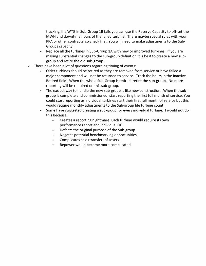
• There have been a lot of questions regarding timing of events: • Older turbines should be retired as they are removed from service or have failed a
major component and will not be returned to service. Track the hours in the Inactive Retired field. When the whole Sub-Group is retired, retire the sub-group. No more reporting will be required on this sub-group.
• The easiest way to handle the new sub-group is like new construction. When the sub-group is complete and commissioned, start reporting the first full month of service. You could start reporting as individual turbines start their first full month of service but this would require monthly adjustments to the Sub-group file turbine count.
• Some have suggested creating a sub-group for every individual turbine. I would not do this because:
• Creates a reporting nightmare. Each turbine would require its own performance report and individual QC.
• Defeats the original purpose of the Sub-group • Negates potential benchmarking opportunities • Complicates sale (transfer) of assets • Repower would become more complicated
RELIABILITY | ACCOUNTABILITY15
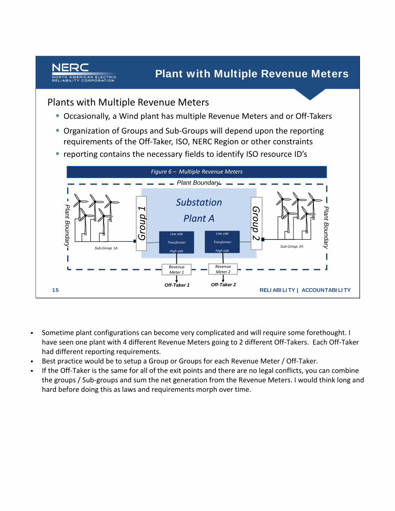
Plant with Multiple Revenue Meters
Plants with Multiple Revenue Meters Occasionally, a Wind plant has multiple Revenue Meters and or Off-Takers
SubstationPlant A
Group 2Grou
p 1
Sub-Group 1A Sub-Group 2A
Low side
Transformer
High side
Off-Taker 1
RevenueMeter 1
Plant B
oundary
Plant Boundary
Plant B
oundary
Figure 6 – Multiple Revenue Meters
Low side
Transformer
High side
Off-Taker 2
RevenueMeter 2
Organization of Groups and Sub-Groups will depend upon the reporting requirements of the Off-Taker, ISO, NERC Region or other constraints
reporting contains the necessary fields to identify ISO resource ID’s
• Sometime plant configurations can become very complicated and will require some forethought. I have seen one plant with 4 different Revenue Meters going to 2 different Off-Takers. Each Off-Taker had different reporting requirements.
• Best practice would be to setup a Group or Groups for each Revenue Meter / Off-Taker. • If the Off-Taker is the same for all of the exit points and there are no legal conflicts, you can combine
the groups / Sub-groups and sum the net generation from the Revenue Meters. I would think long and hard before doing this as laws and requirements morph over time.
RELIABILITY | ACCOUNTABILITY16
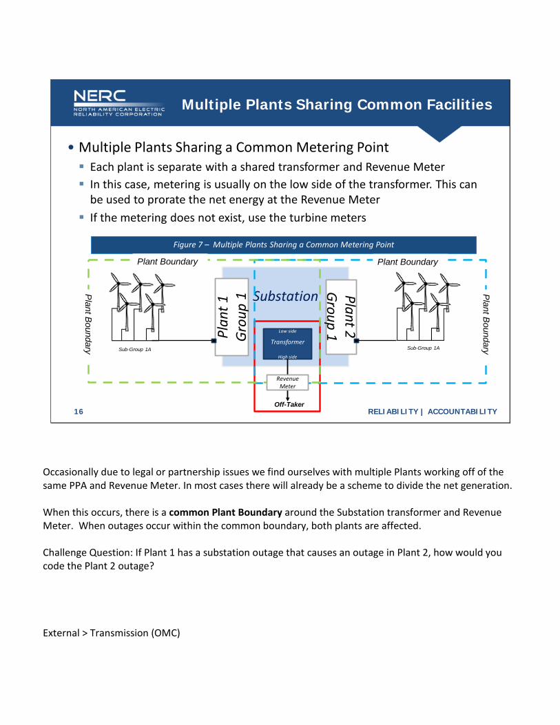
Multiple Plants Sharing Common Facilities
• Multiple Plants Sharing a Common Metering Point Each plant is separate with a shared transformer and Revenue Meter
Substation Plant 2Group 1Pl
ant 1
Grou
p 1
Sub-Group 1A
Low side
Transformer
High side
Off-Taker
Figure 7 – Multiple Plants Sharing a Common Metering Point
Sub-Group 1A
Plant Boundary
Plant B
oundary
RevenueMeter
Plant B
oundary
Plant Boundary
In this case, metering is usually on the low side of the transformer. This can be used to prorate the net energy at the Revenue Meter
If the metering does not exist, use the turbine meters
Occasionally due to legal or partnership issues we find ourselves with multiple Plants working off of the same PPA and Revenue Meter. In most cases there will already be a scheme to divide the net generation. When this occurs, there is a common Plant Boundary around the Substation transformer and Revenue Meter. When outages occur within the common boundary, both plants are affected. Challenge Question: If Plant 1 has a substation outage that causes an outage in Plant 2, how would you code the Plant 2 outage? External > Transmission (OMC)

RELIABILITY | ACCOUNTABILITY17
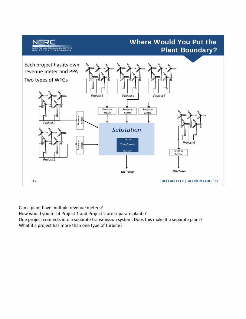
Where Would You Put the Plant Boundary?
SubstationLow side
Transformer
High side
Project 1
Off-Taker
Project 2
Project 3 Project 4 Project 5
Project 6
Reve
nue
Met
erRe
venu
eM
eter
RevenueMeter
RevenueMeter
RevenueMeter
RevenueMeter
Off-Taker
Each project has its own revenue meter and PPATwo types of WTGs
Can a plant have multiple revenue meters? How would you tell if Project 1 and Project 2 are separate plants? One project connects into a separate transmission system. Does this make it a separate plant? What if a project has more than one type of turbine?
RELIABILITY | ACCOUNTABILITY18