Embed Size (px)
Citation preview

www.geartechnology.com June 2010 GEARTECHNOLOGY 63
Micropitting has become a major concern in certain classes of indus-trial gear applications, especially wind power and other relatively highly loaded, somewhat slow-speed applications, where carburized gears are used to facilitate maximum load capacity in a compact package. While by itself the appearance of micropit-ting (Fig. 1) does not generally cause much perturbation in the overall oper-
continued
IntroductionAlthough most frequently associ-
ated with lower speed gear systems, micropitting can also be observed in high and very high-speed gear systems as well, though the failure sequence can be somewhat different at the high-speed end of the spectrum.
Unfortunately, the micropitting phe-nomenon—including the underlying causes and analysis methods directed at prevention in the design stage—is not fully understood. Indeed, even the condition to which the term should be applied is subject to some discussion and disagreement. We do not propose,
The Anatomy of a Micropitting-Induced
Tooth Fracture Failure—Its Causation, Initiation,
Progression and Prevention
Raymond J. Drago, Roy J. Cunningham and Steve Cymbala
(Printed with permission of the copyright holder, the American Gear Manufacturers Association, 500 Montgomery Street, Suite 350, Alexandria, Virginia 22314-1560. Statements presented in this paper are those of the author(s) and may not repre-sent the position or opinion of the American Gear Manufacturers Association.)
herein, to address the greater subjects of classification, analytical evaluation and terminology in a “Standard” sense. Rather, this paper presents a discussion of the initiation, propagation and ulti-mate tooth fracture failure mechanism associated with a micropitting failure.
While micropitting is most often associated with parallel axis gears (spur and helical), the authors have also found this type of distress when evaluating damage to carburized, hardened and hard-finished spiral bevel gears. Micropitting observed on both parallel axis and bevel gears
Management Summaryation of a gear system, the ultimate consequences of a micropitting failure can, and frequently are, much more catastrophic.
Micropitting is most often asso-ciated with parallel axis gears (spur and helical), but the authors have also found this type of distress when evalu-ating damage to carburized, hardened and hard-finished spiral bevel gears.
This paper presents a discussion of
the initiation, propagation and ulti-mate tooth fracture failure mecha-nism associated with a micropitting failure. The subject is presented by way of a discussion of detailed, destructive metallurgical evaluations of several micropitting failures that the authors have analyzed on both parallel axis and bevel gears.
Figure 1—Typical micropitted region.

GEARTECHNOLOGY June 2010 www.geartechnology.com64
will be addressed in this presentation. Although no specific failure “case” is presented, information has been extracted and condensed from several individual actual tooth fracture fail-ure investigations conducted by the authors so that a better understanding of the specific conditions that lead to micropitting—and the actual progres-sion from micropitting to fracture—can be better understood.
Before we can discuss the occur-rence and propagation of micropitting (also known as “grey staining”), we will have to understand what it is and how it differs from classic fatigue pit-ting. Micropitting has become a seri-ous problem in high-quality, usually ground or otherwise hard-finished, carburized industrial gearing—espe-cially in critical applications such as wind turbine, conveyor and some low-er-speed aerospace gearboxes. While the problem is more often observed in parallel axis gears, it is also observed in bevel gears where the contact condi-tions are “right.”
MacropittingUntil fairly recently, surface dura-
bility of gears has been defined by macroscopic pitting, or macropitting, in which a crack initiates at a subsurface location where the shear stress exceeds the shear allowable (Fig. 2A). When such a crack propagates to the tooth surface, a small piece or, more often, several small pieces of material (Fig. 2C) are liberated, leaving an inverted, cove-shaped defect (Fig. 2B).
As this process is repeated, more and more pits appear and eventually the tooth surface is heavily damaged (Fig. 3). Eventually, and if the loads are high enough, the pitting- damaged region of the tooth acts as a signifi-cant stress concentration, and bending fatigue failure of the tooth may occur through the pitted region (Fig. 3B).
MicropittingMore recently (the last 10–15
years) a microscopic pitting phenom-enon—generally referred to as micro-pitting—has become a very problem-atic failure mode in certain applica-tions. Typically, where high loading is present at lower speeds under low or marginal film thickness conditions, micropitting becomes a significant risk.
It is important to note, however, that although it usually appears in a some-what different presentation, micropit-ting is also a factor in the operation of higher-speed gears as well. In the lat-ter instance, micropitting is frequently present as a “hard line’ that leads fairly quickly to the formation of large spalls that may lead rather rapidly to tooth fracture failures; as such, the original micropitting “evidence” is often lost in the failure. Extremely careful metal-lurgical evaluation of the fractures can, however, often pinpoint the micropit-ting “connection” (Figs. 14C and 15).
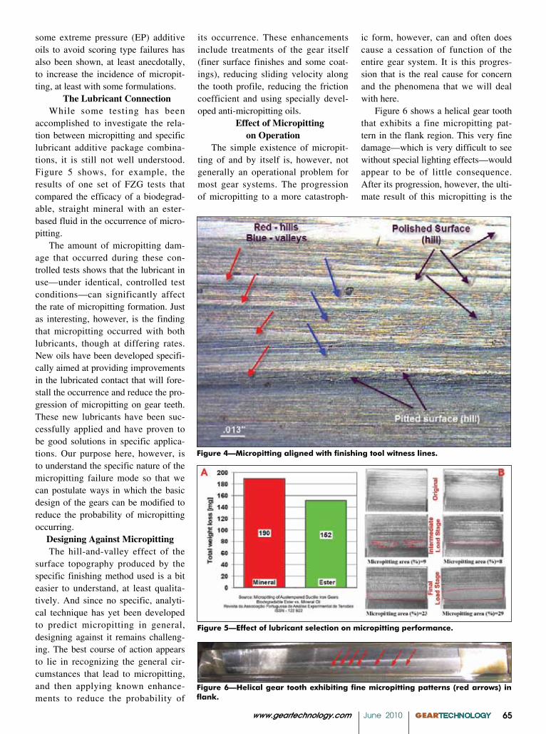
The cause of micropitting remains elusive. Initially, it was thought that the cleanliness of the steel might be play-ing a significant role, but micropitting exists even where very clean steels are used. It appears at local surface irregu-larities, including tooling witness lines (Fig. 4) and general-surface roughness peaks. It has been demonstrated that micropitting capacity can be improved through the use of improved finishing techniques, especially “super finishing” processes that reduce the surface finish down well below 10 RMS. The use of
Figure 2—Classic macropitting fatigue.
Figure 3—Heavy pitting often leads to local tooth fracture.
www.geartechnology.com June 2010 GEARTECHNOLOGY 65
some extreme pressure (EP) additive oils to avoid scoring type failures has also been shown, at least anecdotally, to increase the incidence of micropit-ting, at least with some formulations.
The Lubricant ConnectionWhile some testing has been
accomplished to investigate the rela-tion between micropitting and specific lubricant additive package combina-tions, it is still not well understood. Figure 5 shows, for example, the results of one set of FZG tests that compared the efficacy of a biodegrad-able, straight mineral with an ester-based fluid in the occurrence of micro-pitting.
The amount of micropitting dam-age that occurred during these con-trolled tests shows that the lubricant in use—under identical, controlled test conditions—can significantly affect the rate of micropitting formation. Just as interesting, however, is the finding that micropitting occurred with both lubricants, though at differing rates. New oils have been developed specifi-cally aimed at providing improvements in the lubricated contact that will fore-stall the occurrence and reduce the pro-gression of micropitting on gear teeth. These new lubricants have been suc-cessfully applied and have proven to be good solutions in specific applica-tions. Our purpose here, however, is to understand the specific nature of the micropitting failure mode so that we can postulate ways in which the basic design of the gears can be modified to reduce the probability of micropitting occurring.
Designing Against MicropittingThe hill-and-valley effect of the
surface topography produced by the specific finishing method used is a bit easier to understand, at least qualita-tively. And since no specific, analyti-cal technique has yet been developed to predict micropitting in general, designing against it remains challeng-ing. The best course of action appears to lie in recognizing the general cir-cumstances that lead to micropitting, and then applying known enhance-ments to reduce the probability of
Figure 4—Micropitting aligned with finishing tool witness lines.
Figure 5—Effect of lubricant selection on micropitting performance.
Figure 6—Helical gear tooth exhibiting fine micropitting patterns (red arrows) in flank.
its occurrence. These enhancements include treatments of the gear itself (finer surface finishes and some coat-ings), reducing sliding velocity along the tooth profile, reducing the friction coefficient and using specially devel-oped anti-micropitting oils.
Effect of Micropitting on Operation
The simple existence of micropit-ting of and by itself is, however, not generally an operational problem for most gear systems. The progression of micropitting to a more catastroph-
ic form, however, can and often does cause a cessation of function of the entire gear system. It is this progres-sion that is the real cause for concern and the phenomena that we will deal with here.
Figure 6 shows a helical gear tooth that exhibits a fine micropitting pat-tern in the flank region. This very fine damage—which is very difficult to see without special lighting effects—would appear to be of little consequence. After its progression, however, the ulti-mate result of this micropitting is the

GEARTECHNOLOGY June 2010 www.geartechnology.com66
tooth fractures shown in Figure 7.Certainly, the very minor dam-
age shown in Figure 6 would not, at first review, seem serious enough to cause the very extensive, service-end-ing damage shown in Figure 7. After reviewing a number of gears from similar systems at various stages of progression, the authors were able to develop a history that clearly shows minor, initial damage leading to a cata-strophic result.
Figure 8 shows two views of the same general region of micropitting on a helical gear tooth. The regions shown are magnified views of one of the micropitted regions denoted by the red arrows in Figure 6. This gear, which initially appeared quite similar to the one shown in Figure 6, eventu-ally experienced many service-ending tooth fracture failures such as those shown in Figure 7. In order to examine the mechanism by which the seemingly mild micropitting distress progressed to a complete tooth fracture, we will examine this failure in detail. (Authors’ note: The figures used to illustrate this discussion were taken from several related, individual failure investiga-tions conducted by the authors; thus, each figure does not necessarily show the same gear. Each figure was select-ed from the large number of images accumulated during the course of these investigations so as to best illustrate the point under discussion.)
The Micropitting MechanismA visual examination of each tooth
fracture surface displayed several zones of bending fatigue initiation and propagation. Fatigue was indicated by the many semi-circular beach marks, which are plainly visible. Bending fatigue initiated subsurface from the pitting/spalling and propagated up and over the tip from the drive side to the coast side of the tooth, result-ing in removal of portions of the tooth tip. Fatigue characteristics are revealed in Figure 8—an enlarged view of the fatigue and rough surface topography shown in Figure 7.
As the micropitting progressed, it began to initiate small fan- or triangu-
Figure 8—Magnified view of subsurface fatigue characteristics.
Figure 9—Typical micropitted tooth surface appearance.
Figure 10—Cracks emanating from small spalls in micropitted region.
Figure 7—Helical gear tooth after partial tooth fractures.
B - Schematic ofMultiple Subsurface
Failure Origins

www.geartechnology.com June 2010 GEARTECHNOLOGY 67
continued
'V' shaped Pits along surface
Figure 11—Small cracks propagating from spalls shown in Figure 9.
Figure 12—Micropitting at the tip of a gear tooth due to inadequate profile modification.
Figure 13—Initiation of a spall in a line of micropitting (the “hard line”).
lar-shaped spalls that are not readily apparent through visual examination (Fig. 9A), but are visible with some additional magnification (Fig. 9B).
As the spalls continue to initiate and grow, they propagate by a crack mechanism shown in Figure 10. While these cracks are small, over time they progress and result in larger spalls occurring on the tooth surface. Continued propagation of these cracks into the body of the tooth (Fig. 11) led to the tooth fracture failures necessitat-ing the gear’s removal from service.
Micropitting also very often occurs when the amount of involute modifica-tion provided at the tips and flanks of a mating pair of gear teeth is inadequate to compensate for the deflections that occur under load. In this case, a very fine line of micropitting occurs on the tips of the teeth on one member and on the flanks of the mating member, very close to the lowest point of contact on the tooth. The appearance of this type of micropitting, shown on the tip of one tooth in Figure 12, is slightly
different from that typically observed on the tooth flanks in general, but the basic failure mechanism is quite simi-lar.
A similar line of micropitting will be observed on the flank of the mat-ing gear. This latter damage is often referred to as a “hard line.” The pres-ence of the hard line in the lower dedendum portion of the tooth—where
the bending stresses are quite high—poses a particular danger of tooth frac-ture. The mechanism by which this occurs is shown in Figure 13.
The spalls progress from the hard line (Fig. 13A) via cracks that initiate at or near the surface in the micropit-ted region, then extending into the gear tooth body, until a piece breaks away

GEARTECHNOLOGY June 2010 www.geartechnology.com68
from the tooth surface. This crack mechanism is shown schematically (Fig. 13B) and in sequence (Fig. 13A.)
The Profile Modification Connection
As noted, micropitting is often thought of as being related solely to lower-speed operation. This is not true. But the mechanism of the micropitting-induced failure takes on a somewhat different appearance. For higher-speed gears—especially those which experi-ence significant tooth deflections—if the profile modifications (i.e., tip and/or flank modifications) are not suf-ficient to prevent hard contact near the extremes of contact (at the tip and flank of the tooth in the profile direction), the micropitting often first appears in the form of the very narrow hard line shown in Figure 12. Because this region is in an area of already very high tooth bending stresses—which are themselves already exacerbated by the very high tooth loading on the tooth profile due to the deflection- induced tip contact—very large spalls can occur very quickly, without the spread of micropitting, over even a large portion of the tooth profile.
The real danger in this mechanism is the fact that it occurs in an area of high bending stress. It is thus very likely that one of the spall cracks will progress through the tooth body, caus-ing a tooth bending fatigue failure (Fig. 14).
The initial spall cracks (Fig. 14A) are rather small, and initiate at or near the surface. As these cracks progress, they result in rather large spalls—becoming apparent on the gear tooth surface (Fig. 14C)—since the cracks are initiating at the surface and pro-gressing into the body of the tooth in a relatively short time. One or more of the cracks will progress through the tooth body (Fig. 14B).
When a crack progresses through the tooth body, partial tooth fractures (Fig. 15) will result. But unlike the fractures that occur due to extensive pitting damage, spall-induced fractures are likely to quickly occur after even a small amount of spalling has occurred.
Figure 16—Results of micropitting fatigue testing on ground and superfinished gears.
Figure 14—Micropitting-induced spall progression leading to a tooth bending fatigue fracture failure.
Figure 15—Partial tooth fractures resulting from spall crack progression.

www.geartechnology.com June 2010 GEARTECHNOLOGY 69
Steve Cymbala was a 34-year employee of the Boeing Company where he held the position of staff engineer with the CH-46 Drive Systems Group at the Philadelphia Integrated Defense & Space Group until his retirement in 2003. He joined the Boeing Vertol Division in 1966 as a mechanical engineering technician in the Model CH-46 Equipment Group where he supported design efforts of the various equipment projects, most notably the Rescue Hoist personnel retrieval. In 1968, he transferred to the CH-46 Drive Systems Group where he supported design and sus-taining engineering efforts of the CH-46 helicopter transmissions and shafting until his departure from Boeing in 1970. That year, Cymbala accepted a design engineer position with General Technical Services. While there, he was responsible for all mechanical aspects of a space lab-bound biological experiment—Arabidopsis—sponsored by the University of Pennsylvania. In 1973, he returned to Boeing where he resumed his position in the CH-46 Drive Systems Group. Cymbala has served as a senior drives engineer for Drive Systems Technology, Inc. since 1976, perform-ing complete design functions, as well as client drawing reviews. He also performs field gearbox failure investigations. He has co-authored three technical papers that have been presented at the Mill Gearing Technology Symposium, American Gear Manufacturers Association Fall Technical Meeting and Association of Iron & Steel Technology (AISTech) Technical Meeting.
Ray Drago, chief engineer of Drive Systems Technology, Inc. is active in all areas of mechanical power transmission. These activities include the design and analysis of drive systems for such diverse areas as large, high-speed paper, print-ing and cardboard machinery; commercial marine drives; heart pumps; large oilfield valves; high-speed cable climbing devices; high-speed gas turbine/genera-tor sets; special automotive racing gearboxes; artificial limbs; mine shaft hoists; air- and water-cooled condensers; miniature gear motors (120 in-oz torque range); automatic bolt torquing devices; very large mining and mill gears; municipal and industrial water and waste water processing system drives and small private heli-copter conversions (piston to turbine engines).
Roy J. Cunningham earned a master’s degree in materials–metallurgical engi-neering from Drexel University in 1970 and a bachelor’s degree in metallurgical engineering from the Drexel (University) Institute of Technology in 1967. He pos-sesses more than 35 years’ experience as both professional engineer and engineer-ing consultant, beginning at Boeing Vertol Co. (1967–1973). From 1974–1991, he worked at Boeing Vertol Company as senior staff metallurgical engineer. From 1991 until his retirement in 2000, he worked at Boeing Helicopter Company, serv-ing as senior manager-materials engineering. Programs he worked on included the Chinook, Sea Knight and V22 Osprey aircraft, the Comanche helicopter and JSF aircraft. Cunningham has also served as subcommittee chairman of the Penn State (State College) ARL Advanced Gear materials program for the development and testing of advanced gear materials. He holds one patent and has served on a num-ber of AGMA and other association committees. Cunningham has also produced some 20 technical papers and presentations.
The large spalls shown in Figure 14C all initiate very low on the tooth profile in a region well below the region of single tooth contact (in the transverse plane) where the tooth loads should be very close to zero. The high loading in this region at the tips of the teeth is due to inadequate tooth pro-file modification, thus rendering the load at engagement and disengagement to be very high. Because of the large spalls, such micropitting-induced fail-ure modes are much more serious than those in which micropitting gradually destroys the tooth profile. This is due to the relatively quick progression of cracking into the tooth body and the larger partial—and often total—tooth fractures that ensue.
Sliding Velocity, Friction and Finish
Despite the absence of a clear explanation for micropitting phenom-ena, it is clear that there are several major factors that contribute to the occurrence (or non-occurrence) of this failure mode. The literature provides indirect evidence that, in addition to basic loading and elastohydrodynamic film conditions, sliding velocity, fric-tion coefficient and tooth surface finish (which is certainly interrelated with both friction and sliding as well as the film thickness) are all major factors.
For example, testing conducted by Krantz, et al., found that the micro-pitting fatigue life of carburized and ground gears was improved quite mea-surably by superfinishing the gears after grinding. A sampling of the data from that work (Fig. 16) clearly shows this effect for the gears tested. The test-ing was accomplished with gears that were otherwise identical, thus the life improvement shown can be attributed to the application of the superfinishing process.
ConclusionAs we have seen from this discus-
sion, the anatomy of a micropitting-induced tooth fracture failure is a somewhat complex event that may take many forms. The authors hope that this short discussion of the general nature of this process helps designers to bet-
ter understand this mechanism, thus permitting them to successfully design against its occurrence in real-world applications.


![Analysis of Tooth Interior Fatigue Fracture Using Boundary … · 2020-03-31 · Tooth Interior Fatigue Fracture Calculation Methods MackAldener [1-3] has shown that an analysis method](https://img.pdfslide.us/doc/110x75/5f263f07055e6d2cab506357/analysis-of-tooth-interior-fatigue-fracture-using-boundary-2020-03-31-tooth-interior.jpg)