Embed Size (px)
Citation preview
Technical Report
TR-01-22
Svensk Kärnbränslehantering ABSwedish Nuclear Fueland Waste Management CoBox 5864SE-102 40 Stockholm SwedenTel 08-459 84 00
+46 8 459 84 00Fax 08-661 57 19
+46 8 661 57 19
The anaerobic corrosion ofcarbon steel and cast iron inartificial groundwaters
N R Smart, AEA Technology plc, Culham Science Centre
D J Blackwood, National University of Singapore
L Werme, Svensk Kärnbränslehantering AB
July 2001
Keywords: anaerobic corrosion, steel, cast iron, hydrogen, radioactivewaste.
The anaerobic corrosion ofcarbon steel and cast iron inartificial groundwaters
N R Smart, AEA Technology plc, Culham Science Centre
D J Blackwood, National University of Singapore
L Werme, Svensk Kärnbränslehantering AB
July 2001

2
3
In Sweden, high level radioactive waste will be disposed of in a canister with a copperouter and a cast iron or carbon steel inner. If the iron insert comes into contact withanoxic geological water, anaerobic corrosion leading to the generation of hydrogen willoccur. This paper presents a study of the anaerobic corrosion of carbon steel and cast ironin artificial Swedish granitic groundwaters. Electrochemical methods and gas collectiontechniques were used to assess the mechanisms and rates of corrosion and the associatedhydrogen gas production over a range of conditions. The corrosion rate is high initiallybut is anodically limited by the slow formation of a duplex magnetite film. The effects ofkey environmental parameters such as temperature and ionic strength on the anaerobiccorrosion rate are discussed.
Abstract

4
5
Introduction 7
Experimental procedures 9Materials 9Electrochemical measurements – Atmospheric pressure 10
Static electrodes 10Rotating disc electrodes 11Zero resistance amperometry (ZRA) measurements 12Scratching electrode 12
Electrochemical measurements with hydrogen overpressure 12Weight loss with hydrogen overpressure 13Gas evolution measurements 14
Effect of water immersion 15Effect of surface treatment 15Effect of dissolved ferrous ion concentration 16Effect of radiolysis products 16Ionic strength 16Effect of groundwater composition 16Effect of temperature 16Effect of removing corrosion product 16Comparison of cast iron and carbon steel 16
Results 17Electrochemical measurements – atmospheric pressure 17
Open circuit potential 17Tafel slopes – static electrodes 17Polarisation curves – rotating disc electrode 18Cyclic voltammetry – rotating disc electrode 19Zero resistance amperometry 19Scratching electrode experiments 22Aerated conditions 22Anoxic conditions 23
Electrochemical measurements – hydrogen overpressure 26Weight loss – hydrogen overpressure 26Characterisation of corrosion product 26Gas evolution measurements 27
KBS TR 36 groundwater 27Degree of immersion 27Effect of pre-formed film composition 29Effect of ferrous ion 29Effect of radiolysis products 30Effect of ionic strength 30Effect of groundwater composition 31
Comparison of cast iron with carbon steel 31Effect of removing adherent corrosion product 33
Contents
6
Discussion 35Electrochemical measurements – atmospheric pressure 35
Open circuit potential 35Tafel slopes 35ZRA measurements 36Scratching electrode 37Effect of hydrogen overpressure 38
Corrosion product 38Hydrogen evolution 38
Degree of immersion 39Effect of pre-formed film composition 39Effect of ferrous ion 39Effect of radiolysis products 40Effect of ionic strength 40Effect of groundwater composition 41Effect of temperature 41Comparison of cast iron with carbon steel 42Effect of removing adherent corrosion product 42
Conclusions 43
Acknowledgements 44
References 45
7
Sweden has 12 nuclear reactors in operation at four different sites. These reactors produceabout 50% of all the electricity used in Sweden. By 2010 the current nuclear programmewill have produced approximately 8000 metric tons of spent nuclear fuel. After 30 to 40years of storage in the intermediate storage facility, CLAB, the fuel will be encapsulatedin corrosion resistant disposal containers. After encapsulation, the fuel will be transportedto a geological repository, where the containers will be deposited at a depth of 500 to 700m in granitic rock and surrounded by a bentonite clay backfill material.
Over a period of more than 15 years, an extensive database on groundwater chemistryhas been built up. Despite the fact that the data represent widely spread geographicregions of Sweden, they present a relatively consistent picture. Groundwater in graniticrock in Sweden is oxygen-free and reducing below a depth of 100 to 200 meters. Theredox potential below this depth ranges between –200 and –300 mV on the hydrogenscale and the water has a pH ranging from neutral to mildly alkaline /Smellie et al 1991and Smellie et al 1995/.
Resistance to corrosion can be achieved in several ways. SKB has decided to approach thelong-term corrosion problem by choosing a container material that is as close as possibleto being immune to corrosion under the expected repository conditions. Copper has awide stability range in oxygen-free water /Brookins 1988/ and oxygen-free conditions areexpected during most of the repository performance lifetime. Dissolved sulphides in thegroundwater change the situation, and copper can then corrode by formation of coppersulphide and hydrogen. The concentrations of dissolved sulphide in the near field of thecanister are, however, very low and the corrosion attack on copper will, during longperiods of time, be controlled by the availability of dissolved sulphides.
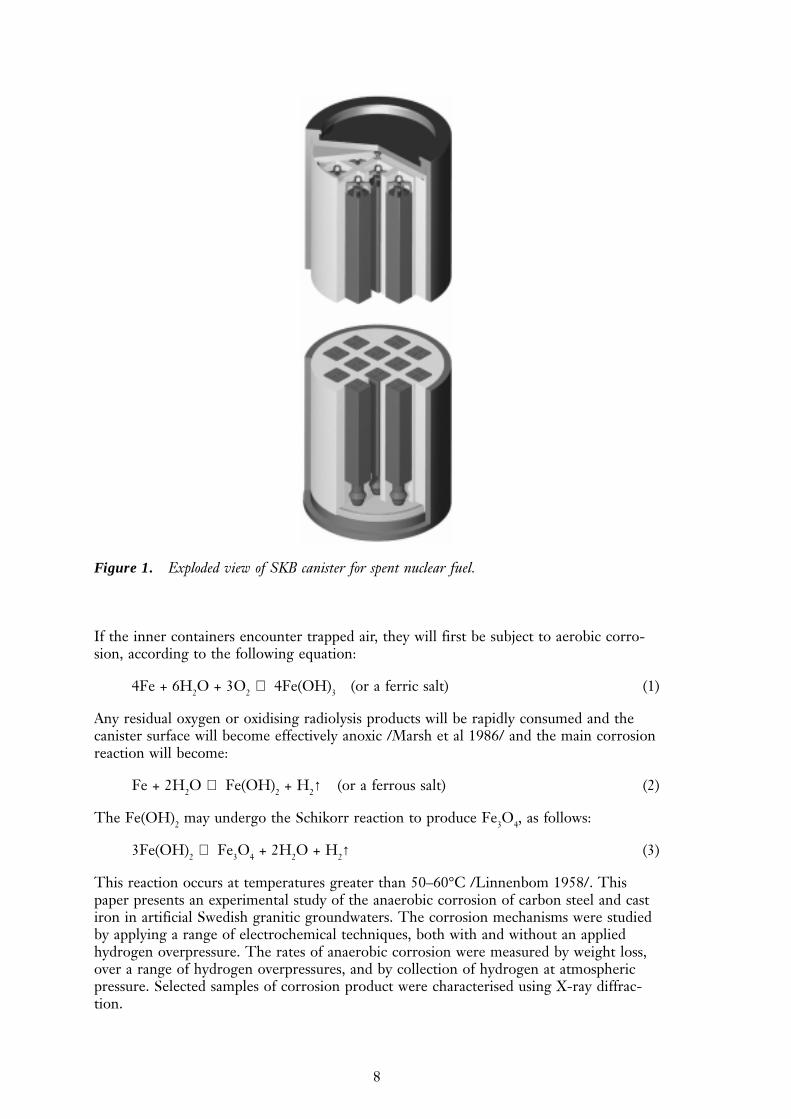
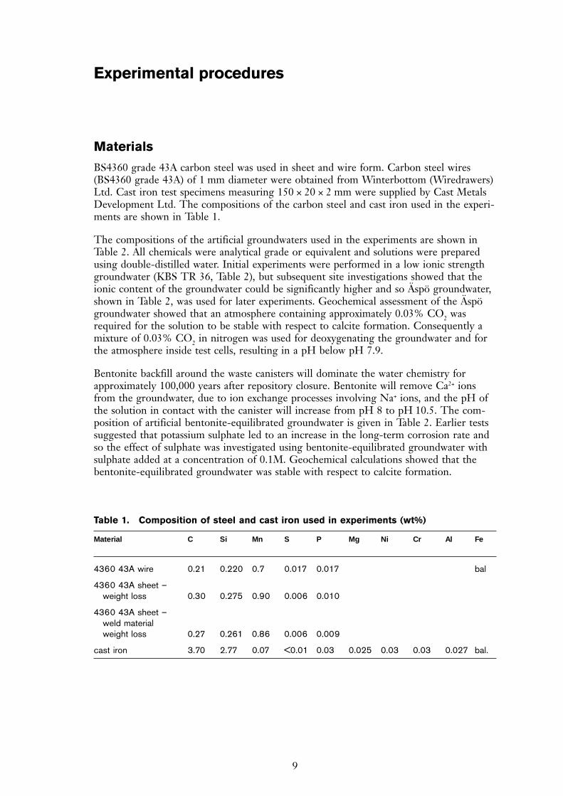
Pure copper does not have sufficient mechanical strength to withstand the external over-pressure of about 14 MPa at the disposal level in the repository. This pressure is composedof a water pressure of 7 MPa, corresponding to a depth of 700m, and 7 MPa swellingpressure from the bentonite. A cast iron or carbon steel insert in the container is, there-fore, used to give the waste package the sufficient mechanical strength, as Figure 1 shows.
If, or when the copper corrosion shield fails, the iron insert will be in contact with oxy-gen-free water and hydrogen-producing, anaerobic corrosion will start. Even though thecopper shell may be penetrated, the container can still act as an important barrier to therelease of radionuclides from the irradiated fuel as long as the container has not col-lapsed. The time during which the failed container will resist the outer overpressure willdepend on the corrosion rate of the iron insert. Furthermore, the hydrogen-producinganaerobic corrosion will result in an environment inside the container that may delay orprevent the release of redox sensitive toxic elements such as plutonium. Hydrogen mayinteract with the surrounding matrix and will eventually permeate out of the repository.Reliable long-term data for the anaerobic corrosion of iron under repository conditionsare, therefore, of fundamental importance for the performance assessment of a repositoryfor spent nuclear fuel.
Introduction
8
If the inner containers encounter trapped air, they will first be subject to aerobic corro-sion, according to the following equation:
4Fe + 6H2O + 3O2 ⇒ 4Fe(OH)3 (or a ferric salt) (1)
Any residual oxygen or oxidising radiolysis products will be rapidly consumed and thecanister surface will become effectively anoxic /Marsh et al 1986/ and the main corrosionreaction will become:
Fe + 2H2O ⇒ Fe(OH)2 + H2↑ (or a ferrous salt) (2)
The Fe(OH)2 may undergo the Schikorr reaction to produce Fe3O4, as follows:
3Fe(OH)2 ⇒ Fe3O4 + 2H2O + H2↑ (3)
This reaction occurs at temperatures greater than 50–60°C /Linnenbom 1958/. Thispaper presents an experimental study of the anaerobic corrosion of carbon steel and castiron in artificial Swedish granitic groundwaters. The corrosion mechanisms were studiedby applying a range of electrochemical techniques, both with and without an appliedhydrogen overpressure. The rates of anaerobic corrosion were measured by weight loss,over a range of hydrogen overpressures, and by collection of hydrogen at atmosphericpressure. Selected samples of corrosion product were characterised using X-ray diffrac-tion.
Figure 1. Exploded view of SKB canister for spent nuclear fuel.
9
Materials
BS4360 grade 43A carbon steel was used in sheet and wire form. Carbon steel wires(BS4360 grade 43A) of 1 mm diameter were obtained from Winterbottom (Wiredrawers)Ltd. Cast iron test specimens measuring 150 × 20 × 2 mm were supplied by Cast MetalsDevelopment Ltd. The compositions of the carbon steel and cast iron used in the experi-ments are shown in Table 1.
The compositions of the artificial groundwaters used in the experiments are shown inTable 2. All chemicals were analytical grade or equivalent and solutions were preparedusing double-distilled water. Initial experiments were performed in a low ionic strengthgroundwater (KBS TR 36, Table 2), but subsequent site investigations showed that theionic content of the groundwater could be significantly higher and so Äspö groundwater,shown in Table 2, was used for later experiments. Geochemical assessment of the Äspögroundwater showed that an atmosphere containing approximately 0.03% CO2 wasrequired for the solution to be stable with respect to calcite formation. Consequently amixture of 0.03% CO2 in nitrogen was used for deoxygenating the groundwater and forthe atmosphere inside test cells, resulting in a pH below pH 7.9.
Bentonite backfill around the waste canisters will dominate the water chemistry forapproximately 100,000 years after repository closure. Bentonite will remove Ca2+ ionsfrom the groundwater, due to ion exchange processes involving Na+ ions, and the pH ofthe solution in contact with the canister will increase from pH 8 to pH 10.5. The com-position of artificial bentonite-equilibrated groundwater is given in Table 2. Earlier testssuggested that potassium sulphate led to an increase in the long-term corrosion rate andso the effect of sulphate was investigated using bentonite-equilibrated groundwater withsulphate added at a concentration of 0.1M. Geochemical calculations showed that thebentonite-equilibrated groundwater was stable with respect to calcite formation.
Experimental procedures
Table 1. Composition of steel and cast iron used in experiments (wt%)
Material C Si Mn S P Mg Ni Cr Al Fe
4360 43A wire 0.21 0.220 0.7 0.017 0.017 bal
4360 43A sheet –weight loss 0.30 0.275 0.90 0.006 0.010
4360 43A sheet –weld materialweight loss 0.27 0.261 0.86 0.006 0.009
cast iron 3.70 2.77 0.07 <0.01 0.03 0.025 0.03 0.03 0.027 bal.
10
Electrochemical measurements – Atmospheric pressure
The following electrochemical measurements were conducted at atmospheric pressure:
• Open circuit potential and Tafel slopes on static wire electrodes
• Polarisation curves, cyclic voltammetry and Tafel slopes for carbon steel in oxic andanoxic groundwater, using a rotating disc electrode to examine mass transport effects.
• Scratching electrode experiments, to investigate how rapidly the film reformed on abare metal surface.
All electrochemical potentials are quoted versus the saturated calomel electrode (SCE).
Static electrodes
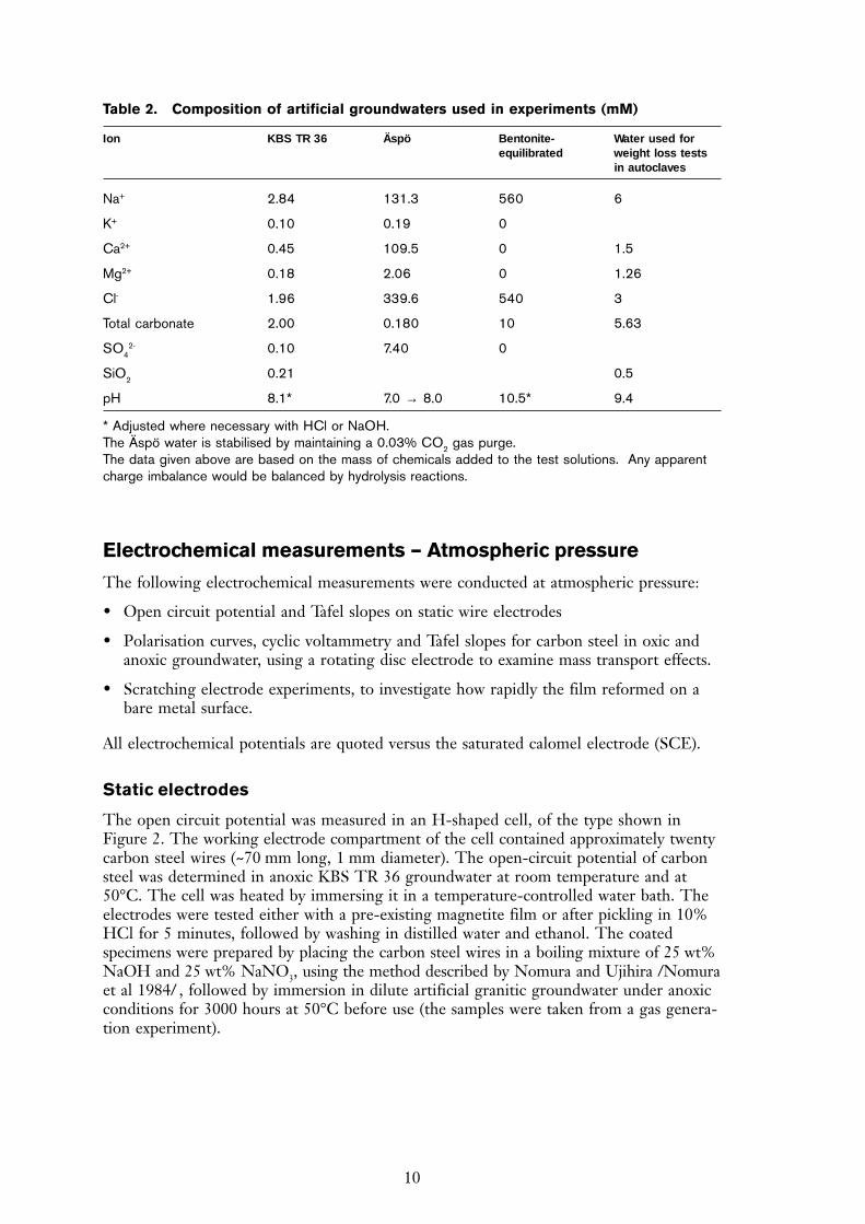
The open circuit potential was measured in an H-shaped cell, of the type shown inFigure 2. The working electrode compartment of the cell contained approximately twentycarbon steel wires (~70 mm long, 1 mm diameter). The open-circuit potential of carbonsteel was determined in anoxic KBS TR 36 groundwater at room temperature and at50°C. The cell was heated by immersing it in a temperature-controlled water bath. Theelectrodes were tested either with a pre-existing magnetite film or after pickling in 10%HCl for 5 minutes, followed by washing in distilled water and ethanol. The coatedspecimens were prepared by placing the carbon steel wires in a boiling mixture of 25 wt%NaOH and 25 wt% NaNO3, using the method described by Nomura and Ujihira /Nomuraet al 1984/ , followed by immersion in dilute artificial granitic groundwater under anoxicconditions for 3000 hours at 50°C before use (the samples were taken from a gas genera-tion experiment).
Table 2. Composition of artificial groundwaters used in experiments (mM)
Ion KBS TR 36 Äspö Bentonite- Water used forequilibrated weight loss tests
in autoclaves
Na+ 2.84 131.3 560 6
K+ 0.10 0.19 0
Ca2+ 0.45 109.5 0 1.5
Mg2+ 0.18 2.06 0 1.26
Cl- 1.96 339.6 540 3
Total carbonate 2.00 0.180 10 5.63
SO42- 0.10 7.40 0
SiO2 0.21 0.5
pH 8.1* 7.0 → 8.0 10.5* 9.4
* Adjusted where necessary with HCl or NaOH.The Äspö water is stabilised by maintaining a 0.03% CO2 gas purge.The data given above are based on the mass of chemicals added to the test solutions. Any apparentcharge imbalance would be balanced by hydrolysis reactions.
11
Tafel slopes for carbon steel, with and without a surface layer of magnetite, were meas-ured using the same cell as that used for the open circuit potential measurements, butonly a single carbon steel wire was present in the working electrode compartment. Theexperiments were performed in a nitrogen-purged glove box (gaseous oxygen concentra-tion ~4 ppm) at approximately 20°C. Under these conditions the pHs of most carbonate-bearing groundwaters are unstable, and so 0.1 M NaCl, adjusted to pH 7.5 with NaOH,was used as the electrolyte. The Tafel slopes were measured by stepping the potential tothe value of interest, in 25 mV steps, and waiting for the current to stabilise, normallyafter 1–2 minutes.
Rotating disc electrodes
A one litre ‘Pyrex’ multi-necked vessel was used for the rotating disc experiments, whichused a 12.7 mm diameter disc of carbon steel. To reduce oxygen diffusion into the cellthe rotating disc electrode passed through a water-lock rotating seal. The working elec-trode connection was made via rotating carbon brush contacts. The cell contained aplatinum counter electrode and a saturated calomel reference electrode connected via aLuggin probe that had a porous zirconia tip and contained 0.1M NaHCO3 electrolyte.To reduce electrical noise the test cell and potentiostat were placed inside an earthedsteel cabinet that served as a Faraday cage. Stainless steel gas lines and compressioncouplings were used for the purge gases, which were high purity nitrogen (99.999%) andcommercial grade mixtures of hydrogen in argon (2.5% or 4% H2). The gases were passedthrough a BASF R3-11 catalyst column operating at 400°C to remove traces of oxygen.The rotating disc assembly was placed inside a PVC bag that was continuously purgedwith pure argon, to provide a second barrier to atmospheric oxygen contamination.Solutions were purged with nitrogen for at least twelve hours prior to the tests and thedegree of deaeration was determined by monitoring the oxygen concentration of the outletgas using an ‘Orbisphere’ gas phase analyser. The outlet oxygen concentration from atypical test cell was of the order of 25 ppm or less, which corresponds to approximately1 ppb dissolved oxygen in solution, assuming a Henry’s law constant, K, of 2.95 × 10/Turnbull et all 1987/. The temperature of the cell was maintained at 25°C throughoutthe test by a thermostatically controlled heating tape.
Figure 2. Schematic of the H-shape cells used to make electrochemical measurements on carbonsteel in anaerobic granitic groundwaters. The cell was divided into two compartments; workingand reference.
12
Polarisation curves were measured for BS 4630 type 43A carbon / manganese steelrotating disc electrodes in 0.01 M sodium hydrogen carbonate, which, when freshlyprepared, had a pH of 8.5–9.0. The measurements were made by firstly holding theelectrode at potential of –1.2V for 1000s, then stepping to the potential of interest andholding for 4000s prior to measurement of the current. Polarisation curves were deter-mined at 10 mV intervals from -920 mV to –550 mV SCE, at rotational speeds rangingfrom 0 to 10 Hz. The open-circuit potential, oxygen concentration and solution pH weremeasured at the beginning and end of each experiment.
Cyclic voltammograms for carbon steel in both normal and ‘bicarbonate-free’ artificialKBS TR 36 groundwater were recorded at 20 mV sec-1 under both aerated and anoxicconditions.
Zero resistance amperometry (ZRA) measurements
If the rate controlling step for anaerobic corrosion is hydrogen diffusion through a corro-sion product film, the effect of connecting a platinum electrode to the carbon steel shoulddepend on whether the film formed is ferrous hydroxide or magnetite based, because theplatinum will act as a cathode and hydrogen will no longer have to diffuse through theoxide film. A series of experiments were carried out using static coupled steel and plati-num electrodes. The solutions and electrode materials were the same as for the polarisa-tion curve experiments. Cylindrical carbon steel electrodes were surrounded by platinumgauze electrodes. The temperature was maintained at either 25°C or 60°C using an ex-ternal heating jacket. The solution was deaerated overnight with either nitrogen or acommercial grade hydrogen / argon mixture (2.5% or 4%), prior to insertion of the steelelectrode. The cell was then further purged until a steady outlet oxygen concentration ofless than 25 ppm was obtained. The purge was then moved from the solution to the gasspace, to avoid agitation of the solution, and the carbon steel and platinum foil electrodeswere connected via a zero resistance ammeter. The couple potential and galvanic currentwere recorded. The duration of the experiments was typically of the order of seven days,but they were terminated at shorter times if the potentials moved above –600 mV SCE.The open-circuit potential, oxygen concentration and solution pH were measured at thebeginning and end of each experiment.
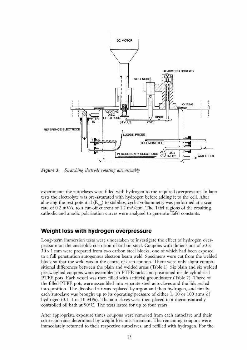
Scratching electrode
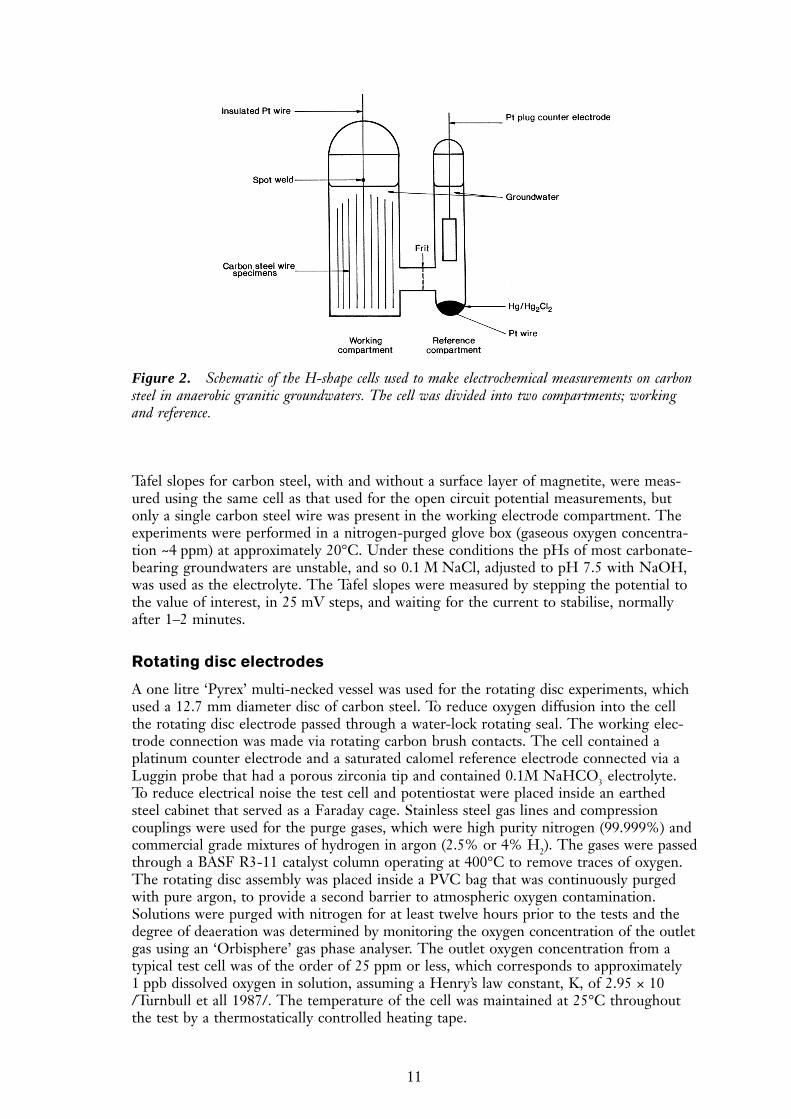
The aim of these experiments was to investigate the stability of the iron hydroxide/mag-netite films formed under anoxic conditions. The electrode surface was scratched in-situby a diamond stylus using a rotating disc scratching electrode assembly (Figure 3). Therotation rate was 10 Hz and the ratio of scratched surface area per revolution to the totalsurface area of the electrode was approximately 1:200. All experiments were carried out ona carbon steel disc electrode, type BS4360 grade 43A, with an area of 0.8 cm2, ground to a600 grit finish. The test solution was initially the artificial groundwater given in Table 2,but in later experiments the bicarbonate component was omitted, to avoid pH drift.
Electrochemical measurements with hydrogen overpressure
Corrosion potential and Tafel slope measurements were performed in autoclaves to assessthe effect of hydrogen overpressure on the kinetics of the anaerobic corrosion reaction.Three electrode cells were prepared in lidded cylindrical PTFE vessels. Each cell con-tained a BS4360 43A forged carbon steel coupon working electrode, a platinum foil counterelectrode, and a calomel reference electrode. Argon-purged 3.5% NaCl solution wasintroduced into the cells inside an argon filled glovebox, and the assembly was placed ina steel autoclave. After sealing, the autoclaves were removed from the glovebox. In some
13
experiments the autoclaves were filled with hydrogen to the required overpressure. In latertests the electrolyte was pre-saturated with hydrogen before adding it to the cell. Afterallowing the rest potential (Erest) to stabilise, cyclic voltammetry was performed at a scanrate of 0.2 mV/s, to a cut-off current of 1.2 mA/cm2. The Tafel regions of the resultingcathodic and anodic polarisation curves were analysed to generate Tafel constants.
Weight loss with hydrogen overpressure
Long-term immersion tests were undertaken to investigate the effect of hydrogen over-pressure on the anaerobic corrosion of carbon steel. Coupons with dimensions of 50 ×30 × 1 mm were prepared from two carbon steel blocks, one of which had been exposedto a full penetration autogenous electron beam weld. Specimens were cut from the weldedblock so that the weld was in the centre of each coupon. There were only slight compo-sitional differences between the plain and welded areas (Table 1). Six plain and six weldedpre-weighed coupons were assembled in PTFE racks and positioned inside cylindricalPTFE pots. Each vessel was then filled with artificial groundwater (Table 2). Three ofthe filled PTFE pots were assembled into separate steel autoclaves and the lids sealedinto position. The dissolved air was replaced by argon and then hydrogen, and finallyeach autoclave was brought up to its operating pressure of either 1, 10 or 100 atms ofhydrogen (0.1, 1 or 10 MPa). The autoclaves were then placed in a thermostaticallycontrolled oil bath at 90°C. The tests lasted for up to four years.
After appropriate exposure times coupons were removed from each autoclave and theircorrosion rates determined by weight loss measurement. The remaining coupons wereimmediately returned to their respective autoclaves, and refilled with hydrogen. For the
Figure 3. Scratching electrode rotating disc assembly
14
coupons that had been exposed for 120 and 343 days the corrected weight loss due tocorrosion was determined by double immersion in Clarke’s solution (folowing ASTMG1-90), but a refined method, using linear regression analysis of the weight losses after2.5, 5, 10 and 20 minutes immersion in Clarke’s solution, was applied to samples exposedfor longer periods. Correlation coefficients for the linear regression were usually betterthan 0.998. The corrosion products on selected specimens were characterised using X-raydiffraction.
Gas evolution measurements
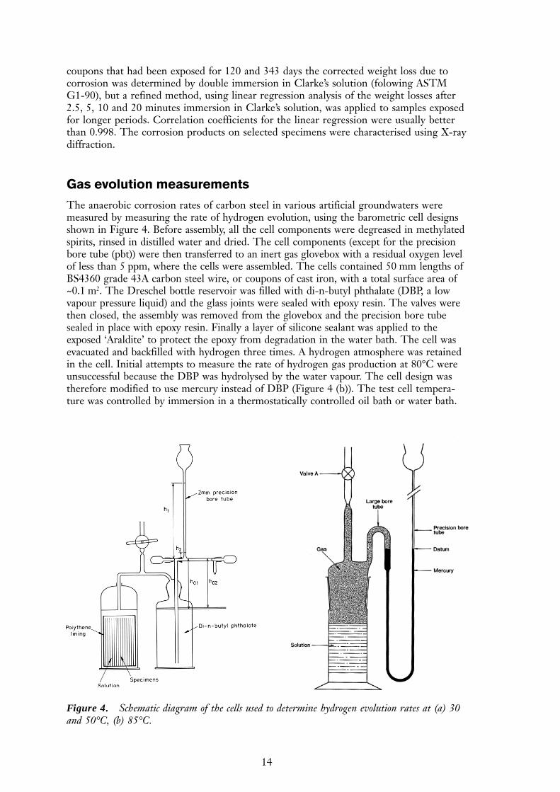
The anaerobic corrosion rates of carbon steel in various artificial groundwaters weremeasured by measuring the rate of hydrogen evolution, using the barometric cell designsshown in Figure 4. Before assembly, all the cell components were degreased in methylatedspirits, rinsed in distilled water and dried. The cell components (except for the precisionbore tube (pbt)) were then transferred to an inert gas glovebox with a residual oxygen levelof less than 5 ppm, where the cells were assembled. The cells contained 50 mm lengths ofBS4360 grade 43A carbon steel wire, or coupons of cast iron, with a total surface area of~0.1 m2. The Dreschel bottle reservoir was filled with di-n-butyl phthalate (DBP, a lowvapour pressure liquid) and the glass joints were sealed with epoxy resin. The valves werethen closed, the assembly was removed from the glovebox and the precision bore tubesealed in place with epoxy resin. Finally a layer of silicone sealant was applied to theexposed ‘Araldite’ to protect the epoxy from degradation in the water bath. The cell wasevacuated and backfilled with hydrogen three times. A hydrogen atmosphere was retainedin the cell. Initial attempts to measure the rate of hydrogen gas production at 80°C wereunsuccessful because the DBP was hydrolysed by the water vapour. The cell design wastherefore modified to use mercury instead of DBP (Figure 4 (b)). The test cell tempera-ture was controlled by immersion in a thermostatically controlled oil bath or water bath.
Figure 4. Schematic diagram of the cells used to determine hydrogen evolution rates at (a) 30and 50°C, (b) 85°C.
15
When corrosion occurred the hydrogen produced caused the liquid level in the manom-eter tube to rise and the new volume of hydrogen in the cell was determined from theheight of the manometer liquid. Hence the volume of hydrogen (DV) produced bycorrosion was calculated. The results were corrected for the external atmospheric pres-sure. Hydrogen evolution rates could be determined to within ±0.5 dm3 (STP) m-2 year-1.Control cells, without any corroding steel, were also set up. A number of experimentalparameters were investigated using the gas cell technique; a summary of the test condi-tions is given in Table 3 and details are given below.
Effect of water immersion
Comparative tests were carried out under high humidity, partial immersion and fullimmersion conditions, by using gas evolution cells with the following arrangements:
• Carbon steel wires fully immersed in artificial KBS TR 36 groundwater;
• Carbon steel wires positioned completely clear of a reservoir of artificial KBS TR 36groundwater;
• Carbon steel wires dipped in KBS TR 36 groundwater so that approximately 20% oftheir surface area was in direct contact with the solution.
Effect of surface treatment
In order to measure the maximum likely hydrogen evolution rate the air-formed oxide filmin most experiments was removed by pickling the wire samples before they were placed inthe barometric cells. The procedure for pickling was to degrease the wires with alcohol,then pickle them in 10% HCl for 5 minutes, followed by three washings in clean double-distilled water to remove any residual acid and finally a rinse with absolute ethanol.
Table 3. Summary of experimental conditions for gas cell experiments
Water Temperature Surface treatment
Swedish granitic GW - KBS TR 36 30 pickled30 degreased50 pickled50 degreased
saturated water vapour – partially immersed and fully in vapour 50 pickled
with magnetite and carbonate films previously formed 50
with 0.1M FeSO4 and 0.1M K2SO4 additions 50 pickled
NH3 addition 50 pickled
HNO3 addition 50 pickled
10´ ionic strength
Äspö groundwater 50 pickled
Bentonite-equilibrated groundwater 50 pickled
Bentonite-equilibrated + sulphate 50 pickled
Äspö groundwater 50 cast iron
Bentonite-equilibrated groundwater 50 cast iron
Äspö groundwater 85 cast iron andcarbon steel
16
To investigate the effect of pre-existing air-formed oxide films on the rate of corrosion,some specimens were tested after a simple degreasing procedure in absolute alcohol. Tostudy the effects of other possible corrosion products on the corrosion rate, tests werealso carried out using carbon steel wires with pre-formed films of either iron(II) carbon-ate or magnetite. Magnetite films were grown using the method described by Nomuraand Ujihira /Nomura et al 1984/. Carbonate films were formed by placing the carbonsteel in a solution of artificial groundwater which was continuously purged with carbondioxide for one to thirty days, at 50ºC.
Effect of dissolved ferrous ion concentration
If the long-term corrosion rate of carbon steel under anaerobic conditions is restrictedby the formation of a protective film, the rate at which the film forms could depend onthe concentration of Fe2+ ions in the surrounding solution. To test this effect, hydrogenevolution experiments were conducted with carbon steel immersed in KBS TR36 ground-water that contained 0.1M FeSO4 or which was saturated with FeCO3.
Effect of radiolysis products
Ammonia and nitric acid are possible radiolysis products from water vapour and nitrogen.Both species may influence the corrosion rate and so experiments were conducted withKBS TR36 groundwater containing 9 mM NH3 or 3 mM HNO3. These are predicted tobe the maximum concentrations inside the canister annulus.
Ionic strength
The effect of ionic strength on the rate of hydrogen evolution was investigated using asolution containing 10× the ionic concentrations of KBS TR36 artificial groundwater.The pH was adjusted to 8.1 with HCl.
Effect of groundwater composition
Gas generation rates were measured in three artificial groundwaters, as shown in Table 2.
Effect of temperature
Gas generation rates were measured at 30°C, 50°C and 85°C.
Effect of removing corrosion product
The effect of removing loosely adhering corrosion product was investigated using carbonsteel wire which had been anaerobically corroded in KBS TR36 artificial groundwater forapproximately two years at 50°C. The loose corrosion product was removed from thesurface by wiping with tissue paper, inside an inert gas glove box. Copious quantities ofcorrosion product were removed, but a layer of black adherent corrosion product remainedon the surface. The cleaned carbon steel wires were then placed in a new gas cell, im-mersed in fresh deaerated KBS TR36 groundwater and reheated to 50°C.
Comparison of cast iron and carbon steel
Gas generation rates were measured for cast iron in Äspö water at 50°C and 85°C, forcomparison with carbon steel corroded in the same waters.
17
Electrochemical measurements – atmospheric pressure
Open circuit potential
The potentials (mV vs SCE) of the pickled mild steel in KBS TR36 groundwater, atroom temperature and at 50°C, were approximately –760 and –815 mV respectively. Forthe unpickled specimens (i.e. those with a surface oxide present) the potentials were –745 mV at room temperature and –795 mV at 50°C. As a corrosion product film devel-oped on the pickled carbon steel electrode a positive shift in its open-circuit potentialoccurred and it converged with that of the unpickled specimen after around 700 hours.The groundwater was at pH 8.1 ± 0.1 throughout the course of the experiment.
Tafel slopes – static electrodes
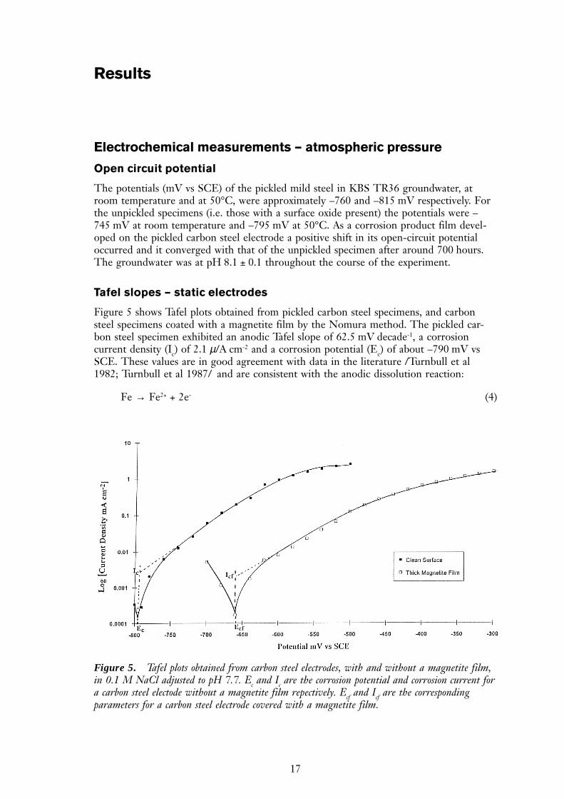
Figure 5 shows Tafel plots obtained from pickled carbon steel specimens, and carbonsteel specimens coated with a magnetite film by the Nomura method. The pickled car-bon steel specimen exhibited an anodic Tafel slope of 62.5 mV decade-1, a corrosioncurrent density (Ic) of 2.1 µ/A cm-2 and a corrosion potential (Ec) of about –790 mV vsSCE. These values are in good agreement with data in the literature /Turnbull et al1982; Turnbull et al 1987/ and are consistent with the anodic dissolution reaction:
Fe → Fe2+ + 2e- (4)
Results
Figure 5. Tafel plots obtained from carbon steel electrodes, with and without a magnetite film,in 0.1 M NaCl adjusted to pH 7.7. Ec and Ic are the corrosion potential and corrosion current fora carbon steel electode without a magnetite film repectively. Ecf and Icf are the correspondingparameters for a carbon steel electrode covered with a magnetite film.
18
The corrosion current density for an ‘oxide free’ carbon steel specimen of 2.1 µA cm-2 isequivalent to a corrosion rate of ~23 µm year-1. At potentials positive of –600 mV vs SCEthe Tafel plot shows that the carbon steel started to form a passive film, which probablyconsisted of Fe(OH)3 or Fe2O3. The presence of an existing magnetite film resulted inthe value of the Tafel slope increasing to 74.1 mV dec-1, the corrosion current density(Icf) decreasing to 0.7 µA cm-2 and the corrosion potential (Ecf) shifting positively toabout -670 mV vs SCE. This value is slightly positive of the water reduction potential atpH 7.5, which is –683 mV vs SCE. The corrosion current density for a magnetite cov-ered carbon steel specimen of 0.7 µA cm-2 is equivalent to a corrosion rate of ~8 µm year-1.
Polarisation curves – rotating disc electrode
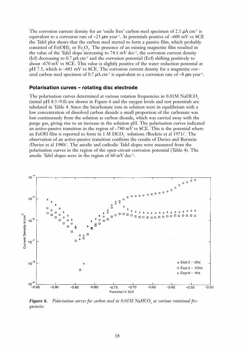
The polarisation curves determined at various rotation frequencies in 0.01M NaHCO3(initial pH 8.5–9.0) are shown in Figure 6 and the oxygen levels and rest potentials aretabulated in Table 4. Since the bicarbonate ions in solution were in equilibrium with alow concentration of dissolved carbon dioxide a small proportion of the carbonate waslost continuously from the solution as carbon dioxide, which was carried away with thepurge gas, giving rise to an increase in the solution pH. The polarisation curves indicatedan active-passive transition in the region of –780 mV vs SCE. This is the potential wherean FeOH film is reported to form in 1 M HCO3
- solutions /Bockris et al 1971/ . Theobservation of an active-passive transition confirms the results of Davies and Burstein/Davies et al 1980/ . The anodic and cathodic Tafel slopes were measured from thepolarisation curves in the region of the open-circuit corrosion potential (Table 4). Theanodic Tafel slopes were in the region of 60 mV dec-1.
Figure 6. Polarisation curves for carbon steel in 0.01M NaHCO3 at various rotational fre-quencies.
19
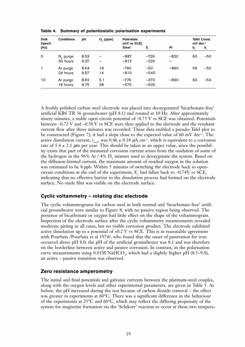
A freshly polished carbon steel electrode was placed into deoxygenated ‘bicarbonate-free’artificial KBS TR 36 groundwater (pH 8.1) and rotated at 10 Hz. After approximatelyninety minutes, a stable open-circuit potential of -0.73 V vs SCE was obtained. Potentialsbetween –0.72 V and –0.50 V vs SCE were then applied to the electrode and the resultantcurrent flow after three minutes was recorded. These data enabled a pseudo-Tafel plot tobe constructed (Figure 7); it had a slope close to the expected value of 60 mV dec-1. Theactive dissolution current, icorr, was 0.46 ± 0.18 µA cm-2, which is equivalent to a corrosionrate of 5.4 ± 2.1 µm per year. This should be taken as an upper value, since the possibil-ity exists that part of the measured corrosion current arises from the oxidation of some ofthe hydrogen in the 96% Ar / 4% H2 mixture used to deoxygenate the system. Based onthe diffusion-limited current, the maximum amount of residual oxygen in the solutionwas estimated to be 8 ppb. Within 5 minutes of switching the electrode back to open-circuit conditions at the end of the experiment, Ec had fallen back to –0.74V vs SCE,indicating that no effective barrier to the dissolution process had formed on the electrodesurface. No oxide film was visible on the electrode surface.
Cyclic voltammetry – rotating disc electrode
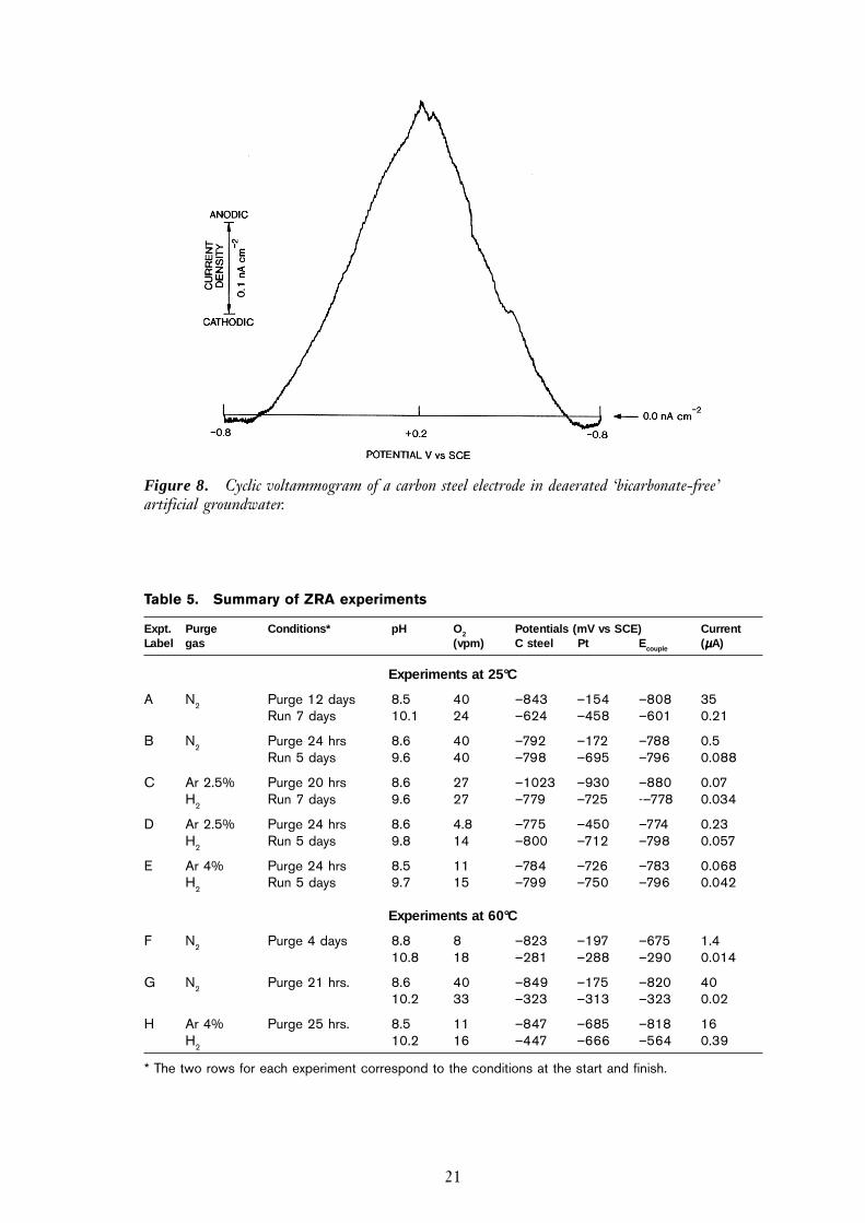
The cyclic voltammograms for carbon steel in both normal and ‘bicarbonate-free’ artifi-cial groundwater were similar to Figure 8, with no passive region being observed. Thepresence of bicarbonate or oxygen had little effect on the shape of the voltammogram.Inspection of the electrode surface after the cyclic voltammetry measurements revealedmoderate pitting in all cases, but no visible corrosion product. The electrode exhibitedactive dissolution up to a potential of +0.2 V vs SCE. This is in reasonable agreementwith Pourbaix /Pourbaix et al 1974/, who found that the onset of passivation for ironoccurred above pH 8.0; the pH of the artificial groundwater was 8.1 and was thereforeon the borderline between active and passive corrosion. In contrast, in the polarisationcurve measurements using 0.01M NaHCO3, which had a slightly higher pH (8.5–9.0),an active – passive transition was observed.
Zero resistance amperometry
The initial and final potentials and galvanic currents between the platinum-steel couples,along with the oxygen levels and other experimental parameters, are given in Table 5. Asbefore, the pH increased during the test because of carbon dioxide removal – the effectwas greater in experiments at 60°C. There was a significant difference in the behaviourof the experiments at 25°C and 60°C, which may reflect the differing propensity of thesystem for magnetite formation via the ‘Schikorr’ reaction to occur at these two tempera-
Table 4. Summary of potentiostatic polarisation experiments
Disk Conditions pH O2 (ppm) Potentials Tafel Const.Speed (mV vs SCE) mV dec-1
(Hz) Steel Ec Pt ba bc
0 N2 purge 8.53 – –887 –726 –820 60 –5030 hours 9.37 – –912 –220 –
1 Ar purge 8.64 19 –790 –50 –860 59 –5024 hours 9.57 14 –610 –540
10 Ar purge 8.62 5.1 –776 –373 –890 63 –5416 hours 9.75 38 –575 –500
20
tures (equation 3). At 25°C, the potential of the couple typically remained at ‘active’potentials (i.e. more negative than –700 mV SCE), throughout the experiments, whichran for approximately seven days. At 60°C the couple potential, though starting at activepotentials, was not stable and generally drifted in a positive direction, rapidly reachingpotentials consistent with the steel electrode having passivated.
The drift to passive potentials at 60°C was also observed when the purge gas was hydro-gen in argon. Having achieved passive potentials the steel was typically more positivethan the platinum foil. This may reflect the fact that the platinum was behaving as ahydrogen electrode, whereas the potential of the steel electrode would have been affected
Figure 7. Pseudo Tafel plot constructed for carbon steel in into deoxygenated ‘bicarbonate-free’Swedish granitic groundwater (pH 8.1) and rotated at 10 Hz
21
Figure 8. Cyclic voltammogram of a carbon steel electrode in deaerated ‘bicarbonate-free’artificial groundwater.
Table 5. Summary of ZRA experiments
Expt. Purge Conditions* pH O2 Potentials (mV vs SCE) CurrentLabel gas (vpm) C steel Pt Ecouple (µµµµµA)
Experiments at 25°C
A N2 Purge 12 days 8.5 40 –843 –154 –808 35Run 7 days 10.1 24 –624 –458 –601 0.21
B N2 Purge 24 hrs 8.6 40 –792 –172 –788 0.5Run 5 days 9.6 40 –798 –695 –796 0.088
C Ar 2.5% Purge 20 hrs 8.6 27 –1023 –930 –880 0.07H2 Run 7 days 9.6 27 –779 –725 -–778 0.034
D Ar 2.5% Purge 24 hrs 8.6 4.8 –775 –450 –774 0.23H2 Run 5 days 9.8 14 –800 –712 –798 0.057
E Ar 4% Purge 24 hrs 8.5 11 –784 –726 –783 0.068H2 Run 5 days 9.7 15 –799 –750 –796 0.042
Experiments at 60°C
F N2 Purge 4 days 8.8 8 –823 –197 –675 1.410.8 18 –281 –288 –290 0.014
G N2 Purge 21 hrs. 8.6 40 –849 –175 –820 4010.2 33 –323 –313 –323 0.02
H Ar 4% Purge 25 hrs. 8.5 11 –847 –685 –818 16H2 10.2 16 –447 –666 –564 0.39
* The two rows for each experiment correspond to the conditions at the start and finish.
22
by the presence of an oxide on the surface of the steel. Reduction of any residual haema-tite would have provided a source of cathodic current and so raised the potential of theelectrode.
At 25°C, with nitrogen as the purge gas, the potential of the platinum electrode whenuncoupled was typically highly positive, approximately –200 mV, indicating that it wasbehaving as an oxygen electrode under the influence of the residual oxygen in the system.With the argon/hydrogen purge gas the platinum behaved as a hydrogen electrode,taking up a potential in the region of –720 to –780 mV, as expected from the solutionpH. In contrast, the potential of the carbon steel-platinum couples was independent ofthe nature of the purge gas, indicating that the oxygen exchange current at the platinumelectrode in the nitrogen purged solution was insufficient to support the steel corrosionprocess.
There was a difference in the magnitudes of the couple currents between nitrogen andargon/hydrogen purged solutions. In the hydrogen-purged solutions the final currentswere generally slightly lower than in the nitrogen-purged experiments. In the nitrogen-purged experiments at 25°C the initial current was high, but subsequently decreased toa steady state current about 1–2 orders of magnitude smaller. Although this fall wasinitially very rapid, the steady state value was generally only achieved after two to threedays. In the hydrogen/argon purged experiments the galvanic current was reasonablysteady throughout (see Table 5).
Scratching electrode experiments
Aerated conditions
A carbon steel electrode placed in air-saturated groundwater (see Table 2) initiallyadopted a rest potential, Ec, of –0.42V vs SCE. On applying a rotation at 10 Hz, Ec rosesignificantly, reaching as high as –0.27 V after a period of some 10 minutes. On stoppingthe rotation, Ec fell slowly, taking several hours to return to its original value. Theseobservations suggest that upon rotation the increase in the mass transport of oxygen tothe electrode surface was sufficient to fully overcome the active dissolution process andthus allow a passive Fe2O3 film to form, hence the rise in the value of Ec. When rotationceased, the open-circuit potential was controlled by the slow dissolution of the Fe2O3film.
On most occasions, pitting occurred on the carbon steel electrode within two hours ofbeing placed in solution, regardless of whether or not it had been rotated. The nuclea-tion time depended on surface roughness. Pits were clearly visible to the naked eye, andwere usually shallow but broad. Copious quantities of black corrosion product were alsoobserved over the electrode surface. Pitting corrosion occurred at rates high enough toforce Ec down to –0.66 V vs SCE. The decrease in potential was due to an increase inthe overpotential for oxygen reduction required to compensate for the increase in thecorrosion rate at the freshly exposed metal surface.
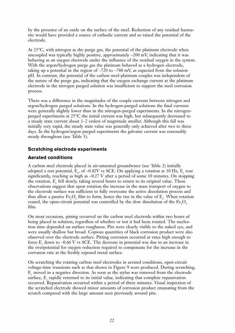
On scratching the rotating carbon steel electrodes in aerated conditions, open-circuitvoltage-time transients such as that shown in Figure 9 were produced. During scratching,Ec moved in a negative direction. As soon as the stylus was removed from the electrodesurface, Ec rapidly returned to its initial value, indicating that complete repassivationoccurred. Repassivation occurred within a period of three minutes. Visual inspection ofthe scratched electrode showed minor amounts of corrosion product emanating from thescratch compared with the large amount seen previously around pits.
23
Anoxic conditions
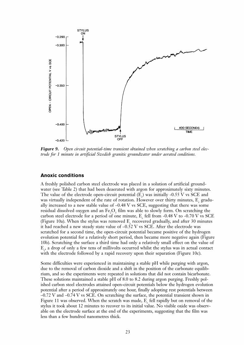
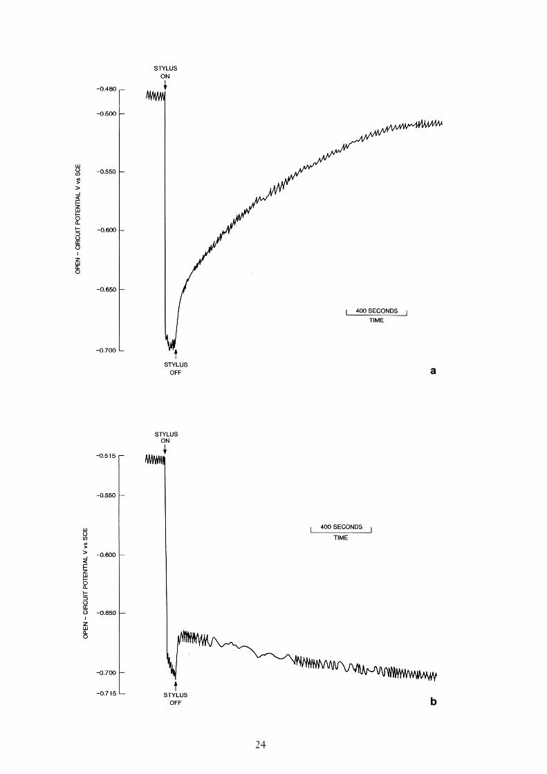
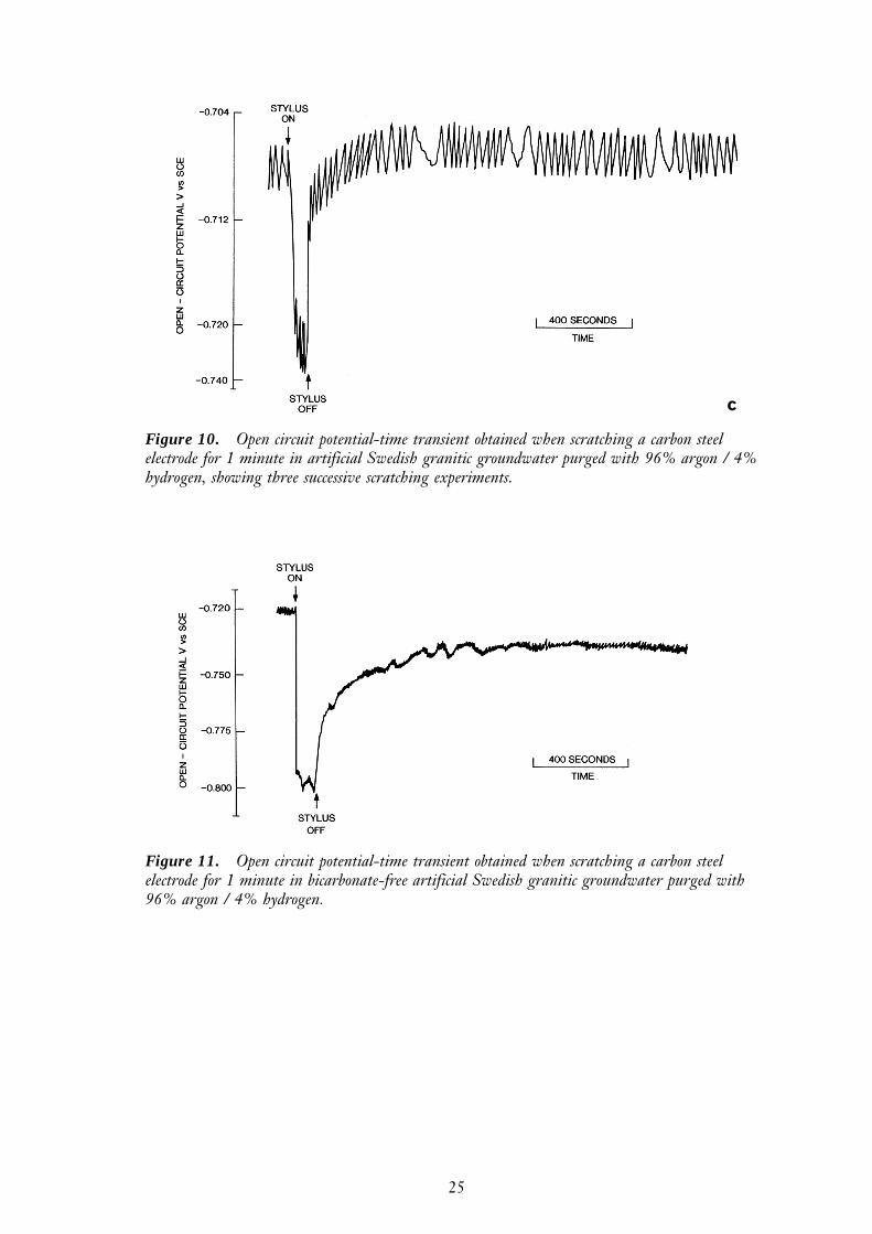
A freshly polished carbon steel electrode was placed in a solution of artificial ground-water (see Table 2) that had been deaerated with argon for approximately sixty minutes.The value of the electrode open-circuit potential (Ec) was initially -0.55 V vs SCE andwas virtually independent of the rate of rotation. However over thirty minutes, Ec gradu-ally increased to a new stable value of –0.48 V vs SCE, suggesting that there was someresidual dissolved oxygen and an Fe2O3 film was able to slowly form. On scratching thecarbon steel electrode for a period of one minute, Ec fell from -0.48 V to -0.70 V vs SCE(Figure 10a). When the stylus was removed Ec recovered gradually, and after 30 minutesit had reached a new steady state value of –0.52 V vs SCE. After the electrode wasscratched for a second time, the open-circuit potential became positive of the hydrogenevolution potential for a relatively short period, then became more negative again (Figure10b). Scratching the surface a third time had only a relatively small effect on the value ofEc, a drop of only a few tens of millivolts occurred whilst the stylus was in actual contactwith the electrode followed by a rapid recovery upon their separation (Figure 10c).
Some difficulties were experienced in maintaining a stable pH while purging with argon,due to the removal of carbon dioxide and a shift in the position of the carbonate equilib-rium, and so the experiments were repeated in solutions that did not contain bicarbonate.These solutions maintained a stable pH of 8.0 to 8.2 during argon purging. Freshly pol-ished carbon steel electrodes attained open-circuit potentials below the hydrogen evolutionpotential after a period of approximately one hour, finally adopting rest potentials between–0.72 V and –0.74 V vs SCE. On scratching the surface, the potential transient shown inFigure 11 was observed. When the scratch was made, Ec fell rapidly but on removal of thestylus it took about 12 minutes to recover to its initial value. No visible oxide was observ-able on the electrode surface at the end of the experiments, suggesting that the film wasless than a few hundred nanometres thick.
Figure 9. Open circuit potential-time transient obtained when scratching a carbon steel elec-trode for 1 minute in artificial Swedish granitic groundwater under aerated conditions.
24
a
b
25
Figure 10. Open circuit potential-time transient obtained when scratching a carbon steelelectrode for 1 minute in artificial Swedish granitic groundwater purged with 96% argon / 4%hydrogen, showing three successive scratching experiments.
c
Figure 11. Open circuit potential-time transient obtained when scratching a carbon steelelectrode for 1 minute in bicarbonate-free artificial Swedish granitic groundwater purged with96% argon / 4% hydrogen.
26
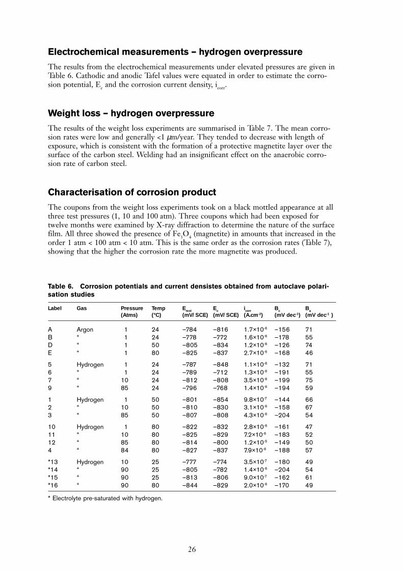
Electrochemical measurements – hydrogen overpressure
The results from the electrochemical measurements under elevated pressures are given inTable 6. Cathodic and anodic Tafel values were equated in order to estimate the corro-sion potential, Ec and the corrosion current density, icorr.
Weight loss – hydrogen overpressure
The results of the weight loss experiments are summarised in Table 7. The mean corro-sion rates were low and generally <1 µm/year. They tended to decrease with length ofexposure, which is consistent with the formation of a protective magnetite layer over thesurface of the carbon steel. Welding had an insignificant effect on the anaerobic corro-sion rate of carbon steel.
Characterisation of corrosion product
The coupons from the weight loss experiments took on a black mottled appearance at allthree test pressures (1, 10 and 100 atm). Three coupons which had been exposed fortwelve months were examined by X-ray diffraction to determine the nature of the surfacefilm. All three showed the presence of Fe3O4 (magnetite) in amounts that increased in theorder 1 atm < 100 atm < 10 atm. This is the same order as the corrosion rates (Table 7),showing that the higher the corrosion rate the more magnetite was produced.
Table 6. Corrosion potentials and current densistes obtained from autoclave polari-sation studies
Label Gas Pressure Temp Erest Ec icorr Bc Ba
(Atms) (°C) (mV/SCE) (mV/SCE) (A.cm-2) (mV dec-1) (mV dec-1 )
A Argon 1 24 –784 –816 1.7×10⁻⁶ –156 71B “ 1 24 –778 –772 1.6×10⁻⁶ –178 55D “ 1 50 –805 –834 1.2×10⁻⁶ –126 74E “ 1 80 –825 –837 2.7×10⁻⁶ –168 46
5 Hydrogen 1 24 –787 –848 1.1×10⁻⁶ –132 716 “ 1 24 –789 –712 1.3×10⁻⁶ –191 557 “ 10 24 –812 –808 3.5×10⁻⁶ –199 759 “ 85 24 –796 –768 1.4×10⁻⁶ –194 59
1 Hydrogen 1 50 –801 –854 9.8×10⁻⁷ –144 662 “ 10 50 –810 –830 3.1×10⁻⁶ –158 673 “ 85 50 –807 –808 4.3×10⁻⁶ –204 54
10 Hydrogen 1 80 –822 –832 2.8×10⁻⁶ –161 4711 “ 10 80 –825 –829 7.2×10⁻⁶ –183 5212 “ 85 80 –814 –800 1.2×10⁻⁵ –149 504 “ 84 80 –827 –837 7.9×10⁻⁶ –188 57
*13 Hydrogen 10 25 –777 –774 3.5×10⁻⁷ –180 49*14 “ 90 25 –805 –782 1.4×10⁻⁶ –204 54*15 “ 90 25 –813 –806 9.0×10⁻⁷ –162 61*16 “ 90 80 –844 –829 2.0×10⁻⁶ –170 49
* Electrolyte pre-saturated with hydrogen.
27
Gas evolution measurements
The results of the gas generation experiments are expressed as (i) corrosion rate inµm yr-1, calculated assuming Fe3O4 was the corrosion product, and (ii) the volume of gasproduced in dm3 H2 m
-2 yr-1. The volumes of gas produced were normalised to standardtemperature (273K, 0°C) and pressure (760 mm Hg). The ‘instantaneous’ corrosion rates,determined from the volume of gas evolved between regular readings divided by theelapsed time between readings, are presented graphically as a function of exposure periodfor various test environments. Control cells, that contained no carbon steel, gave back-ground changes of <0.2 dm3 m-2 year-1 at 50°C. In the next sections, the effects of thevarious environmental variables on the anaerobic corrosion rates of carbon steel aresummarised.
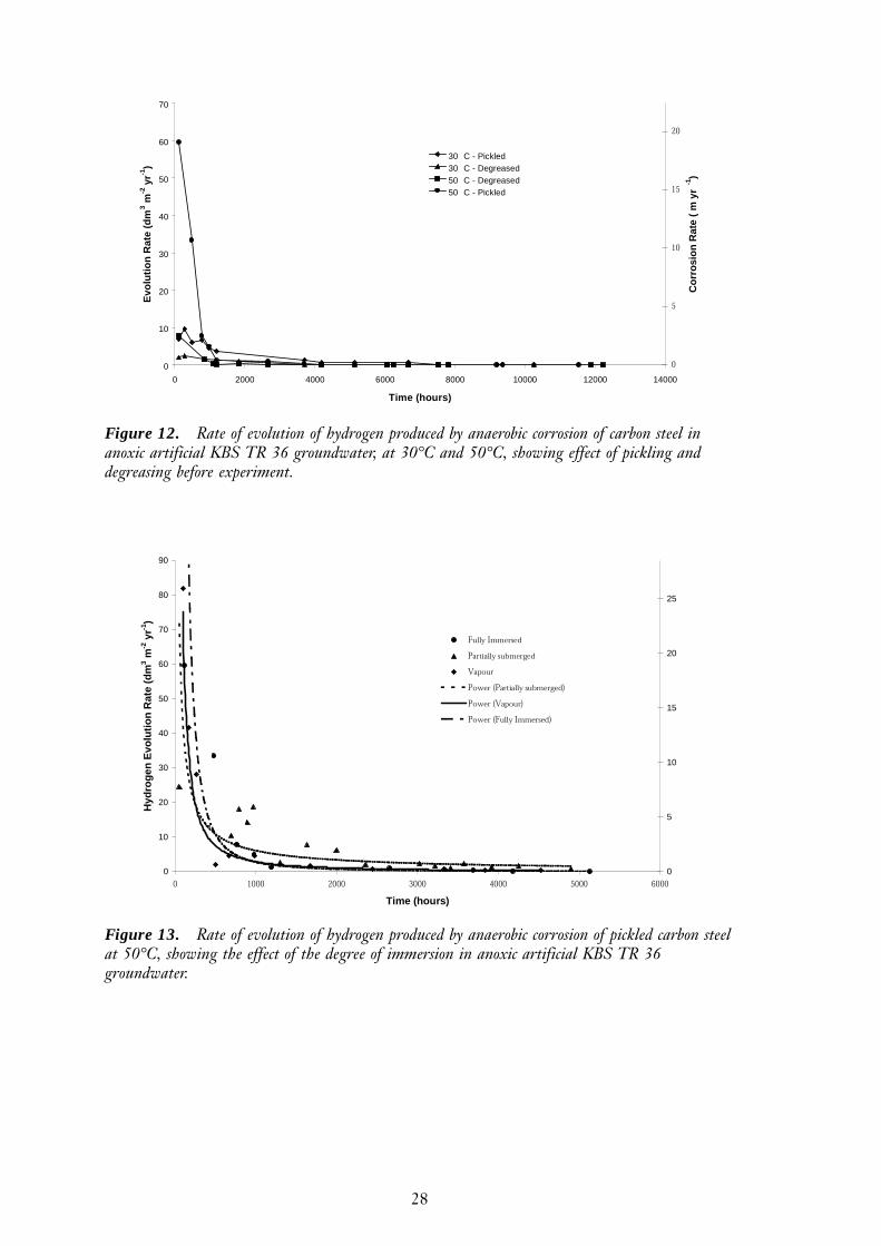
KBS TR 36 groundwater
The results of the hydrogen evolution tests in KBS TR 36 groundwater at 30°C and50°C are presented in Figure 12. Samples that were pickled showed higher initial ratesthan samples that were only degreased. The corrosion rate declined with increasingexposure time, with >95% decline occurring during the first 1500 hours. The corrosionrate was higher at 50°C than at 30°C. These results were used as a baseline measurementto be compared with other test environments. In subsequent experiments the specimenswere always used in the pickled condition unless otherwise stated.
Degree of immersion
The effect of the degree of immersion on the gas generation rate is shown in Figure 13.Differences were observed in the initial hydrogen production rates and the rate of declineas a protective corrosion product layer developed. The hydrogen production rate forpartially-submerged carbon steel wires was initially less than for totally submerged wiresor wires which were clear of the groundwater. The partially-submerged wires also exhib-ited a slower rate of decline in hydrogen production rate, even though a black magnetitefilm was clearly visible over most of the surface. The total amount of hydrogen producedby the partially immersed wires after 5000 hours was about 10% larger than from thefully immersed wires, suggesting that the final thicknesses of the protective magnetitelayers were similar.
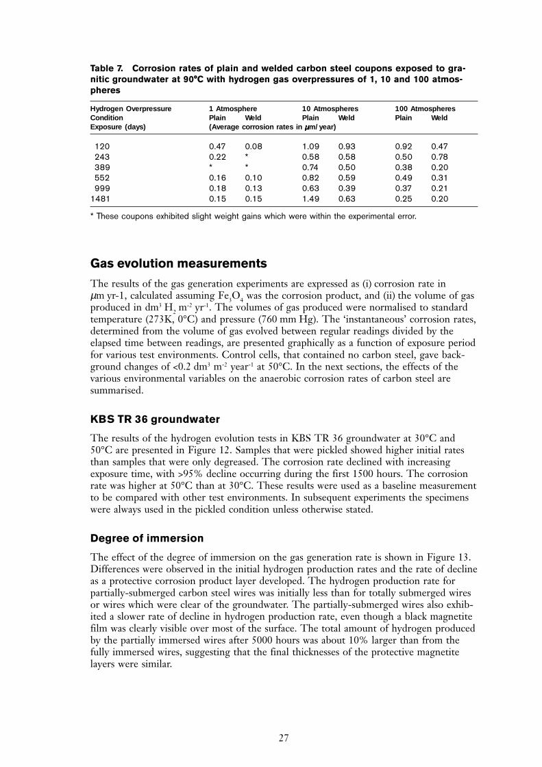
Table 7. Corrosion rates of plain and welded carbon steel coupons exposed to gra-nitic groundwater at 90°C with hydrogen gas overpressures of 1, 10 and 100 atmos-pheres
Hydrogen Overpressure 1 Atmosphere 10 Atmospheres 100 AtmospheresCondition Plain Weld Plain Weld Plain WeldExposure (days) (Average corrosion rates in µµµµµm/year)
120 0.47 0.08 1.09 0.93 0.92 0.47243 0.22 * 0.58 0.58 0.50 0.78389 * * 0.74 0.50 0.38 0.20552 0.16 0.10 0.82 0.59 0.49 0.31999 0.18 0.13 0.63 0.39 0.37 0.21
1481 0.15 0.15 1.49 0.63 0.25 0.20
* These coupons exhibited slight weight gains which were within the experimental error.
28
0
10
20
30
40
50
60
70
0 2000 4000 6000 8000 10000 12000 14000
Time (hours)
Evo
luti
on
Rat
e (d
m3 m
-2 y
r-1)
�
�
��
��
��
Co
rro
sio
n R
ate
(m
yr
-1)
30 C - Pickled30 C - Degreased50 C - Degreased50 C - PickledSeries6
Figure 12. Rate of evolution of hydrogen produced by anaerobic corrosion of carbon steel inanoxic artificial KBS TR 36 groundwater, at 30°C and 50°C, showing effect of pickling anddegreasing before experiment.
0
10
20
30
40
50
60
70
80
90
� ���� ���� ���� ���� ���� ����
Time (hours)
Hyd
rog
en E
volu
tio
n R
ate
(dm
3 m-2
yr-1
)
0
5
10
15
20
25
��� �������
����������������
�����
������������������������
�������������
���������� ��������
Figure 13. Rate of evolution of hydrogen produced by anaerobic corrosion of pickled carbon steelat 50°C, showing the effect of the degree of immersion in anoxic artificial KBS TR 36groundwater.
29
Effect of pre-formed film composition
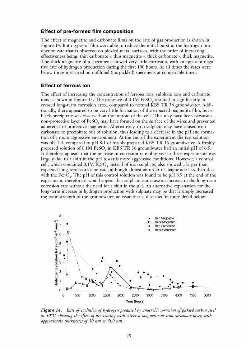
The effect of magnetite and carbonate films on the rate of gas production is shown inFigure 14. Both types of film were able to reduce the initial burst in the hydrogen pro-duction rate that is observed on pickled metal surfaces, with the order of increasingeffectiveness being: thin carbonate < thin magnetite < thick carbonate < thick magnetite.The thick magnetite film specimens showed very little corrosion, with an apparent nega-tive rate of hydrogen production during the first 100 hours. At all times the rates werebelow those measured on unfilmed (i.e. pickled) specimens at comparable times.
Effect of ferrous ion
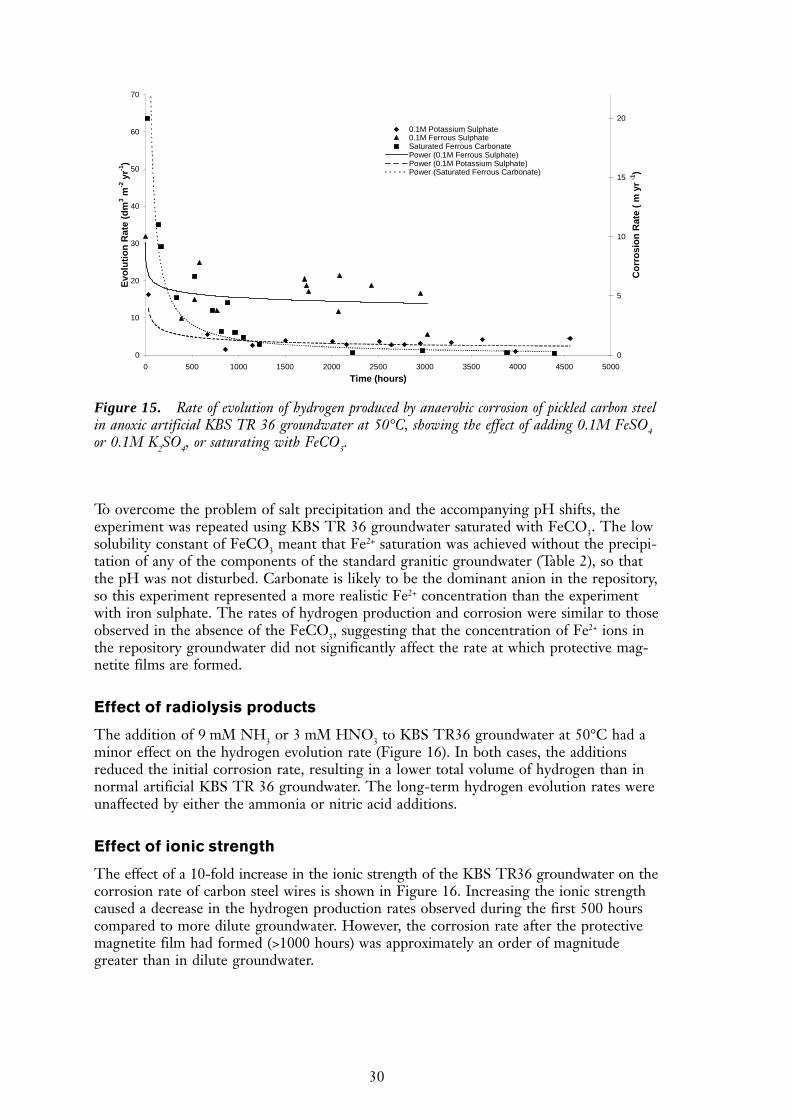
The effect of increasing the concentration of ferrous ions, sulphate ions and carbonateions is shown in Figure 15. The presence of 0.1M FeSO4 resulted in significantly in-creased long-term corrosion rates, compared to normal KBS TR 36 groundwater. Addi-tionally, there appeared to be very little formation of the expected magnetite film, but ablack precipitate was observed on the bottom of the cell. This may have been because anon-protective layer of FeSO4 may have formed on the surface of the wires and preventedadherence of protective magnetite. Alternatively, iron sulphate may have caused ironcarbonate to precipitate out of solution, thus leading to a decrease in the pH and forma-tion of a more aggressive environment. At the end of the experiment the test solutionwas pH 7.3, compared to pH 8.1 of freshly prepared KBS TR 36 groundwater. A freshlyprepared solution of 0.1M FeSO4 in KBS TR 36 groundwater had an initial pH of 6.5.It therefore appears that the increase in corrosion rate observed in these experiments waslargely due to a shift in the pH towards more aggressive conditions. However, a controlcell, which contained 0.1M K2SO4 instead of iron sulphate, also showed a larger thanexpected long-term corrosion rate, although almost an order of magnitude less than thatwith the FeSO4. The pH of this control solution was found to be pH 8.9 at the end of theexperiment, therefore it would appear that sulphate can cause an increase in the long-termcorrosion rate without the need for a shift in the pH. An alternative explanation for thelong-term increase in hydrogen production with sulphate may be that it simply increasedthe ionic strength of the groundwater, an issue that is discussed in more detail below.
0
1
2
3
4
5
6
7
8
0 500 1000 1500 2000 2500 3000 3500 4000 4500 5000
Time (Hours)
Hyd
rog
en E
volu
tio
n R
ate
(dm
3 m-2
yea
r-1) Thin Magnetite
Thick MagnetiteThin CarbonateThick Carbonate
Figure 14. Rate of evolution of hydrogen produced by anaerobic corrosion of pickled carbon steelat 50°C, showing the effect of pre-coating with either a magnetite or iron carbonate layer, withapproximate thicknesses of 50 nm or 500 nm.
30
To overcome the problem of salt precipitation and the accompanying pH shifts, theexperiment was repeated using KBS TR 36 groundwater saturated with FeCO3. The lowsolubility constant of FeCO3 meant that Fe2+ saturation was achieved without the precipi-tation of any of the components of the standard granitic groundwater (Table 2), so thatthe pH was not disturbed. Carbonate is likely to be the dominant anion in the repository,so this experiment represented a more realistic Fe2+ concentration than the experimentwith iron sulphate. The rates of hydrogen production and corrosion were similar to thoseobserved in the absence of the FeCO3, suggesting that the concentration of Fe2+ ions inthe repository groundwater did not significantly affect the rate at which protective mag-netite films are formed.
Effect of radiolysis products
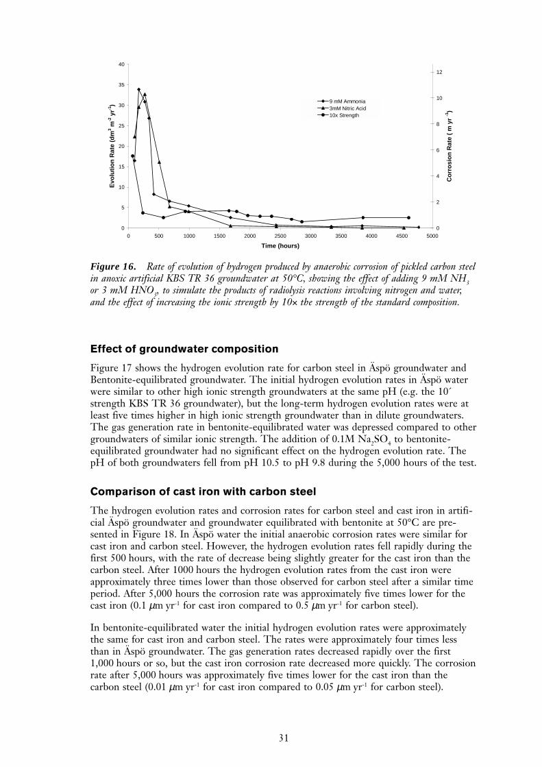
The addition of 9 mM NH3 or 3 mM HNO3 to KBS TR36 groundwater at 50°C had aminor effect on the hydrogen evolution rate (Figure 16). In both cases, the additionsreduced the initial corrosion rate, resulting in a lower total volume of hydrogen than innormal artificial KBS TR 36 groundwater. The long-term hydrogen evolution rates wereunaffected by either the ammonia or nitric acid additions.
Effect of ionic strength
The effect of a 10-fold increase in the ionic strength of the KBS TR36 groundwater on thecorrosion rate of carbon steel wires is shown in Figure 16. Increasing the ionic strengthcaused a decrease in the hydrogen production rates observed during the first 500 hourscompared to more dilute groundwater. However, the corrosion rate after the protectivemagnetite film had formed (>1000 hours) was approximately an order of magnitudegreater than in dilute groundwater.
0
10
20
30
40
50
60
70
0 500 1000 1500 2000 2500 3000 3500 4000 4500 5000
Time (hours)
Evo
luti
on
Rat
e (d
m3 m
-2 y
r-1)
0
5
10
15
20
Co
rro
sio
n R
ate
(m
yr
-1)
0.1M Potassium Sulphate0.1M Ferrous SulphateSaturated Ferrous CarbonatePower (0.1M Ferrous Sulphate)Power (0.1M Potassium Sulphate)Power (Saturated Ferrous Carbonate)
Figure 15. Rate of evolution of hydrogen produced by anaerobic corrosion of pickled carbon steelin anoxic artificial KBS TR 36 groundwater at 50°C, showing the effect of adding 0.1M FeSO4or 0.1M K2SO4, or saturating with FeCO3.
31
Effect of groundwater composition
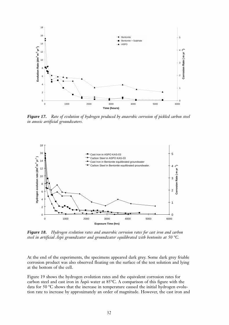
Figure 17 shows the hydrogen evolution rate for carbon steel in Äspö groundwater andBentonite-equilibrated groundwater. The initial hydrogen evolution rates in Äspö waterwere similar to other high ionic strength groundwaters at the same pH (e.g. the 10´strength KBS TR 36 groundwater), but the long-term hydrogen evolution rates were atleast five times higher in high ionic strength groundwater than in dilute groundwaters.The gas generation rate in bentonite-equilibrated water was depressed compared to othergroundwaters of similar ionic strength. The addition of 0.1M Na2SO4 to bentonite-equilibrated groundwater had no significant effect on the hydrogen evolution rate. ThepH of both groundwaters fell from pH 10.5 to pH 9.8 during the 5,000 hours of the test.
Comparison of cast iron with carbon steel
The hydrogen evolution rates and corrosion rates for carbon steel and cast iron in artifi-cial Äspö groundwater and groundwater equilibrated with bentonite at 50°C are pre-sented in Figure 18. In Äspö water the initial anaerobic corrosion rates were similar forcast iron and carbon steel. However, the hydrogen evolution rates fell rapidly during thefirst 500 hours, with the rate of decrease being slightly greater for the cast iron than thecarbon steel. After 1000 hours the hydrogen evolution rates from the cast iron wereapproximately three times lower than those observed for carbon steel after a similar timeperiod. After 5,000 hours the corrosion rate was approximately five times lower for thecast iron (0.1 µm yr-1 for cast iron compared to 0.5 µm yr-1 for carbon steel).
In bentonite-equilibrated water the initial hydrogen evolution rates were approximatelythe same for cast iron and carbon steel. The rates were approximately four times lessthan in Äspö groundwater. The gas generation rates decreased rapidly over the first1,000 hours or so, but the cast iron corrosion rate decreased more quickly. The corrosionrate after 5,000 hours was approximately five times lower for the cast iron than thecarbon steel (0.01 µm yr-1 for cast iron compared to 0.05 µm yr-1 for carbon steel).
0
5
10
15
20
25
30
35
40
0 500 1000 1500 2000 2500 3000 3500 4000 4500 5000
Time (hours)
Evo
luti
on
Rat
e (d
m3 m
-2 y
r-1)
0
2
4
6
8
10
12
Co
rro
sio
n R
ate
(m
yr
-1)
9 mM Ammonia3mM Nitric Acid10x Strength
Figure 16. Rate of evolution of hydrogen produced by anaerobic corrosion of pickled carbon steelin anoxic artificial KBS TR 36 groundwater at 50°C, showing the effect of adding 9 mM NH3or 3 mM HNO3, to simulate the products of radiolysis reactions involving nitrogen and water,and the effect of increasing the ionic strength by 10× the strength of the standard composition.
32
0
2
4
6
8
10
12
14
16
18
0 1000 2000 3000 4000 5000 6000
Time (hours)
Evo
luti
on
Rat
e (d
m3 m
-2 y
r-1)
0
1
2
3
4
5
Co
rro
sio
n R
ate
(m
yr
-1)
Bentonite
Bentonite + Sulphate
ASPO
Figure 17. Rate of evolution of hydrogen produced by anaerobic corrosion of pickled carbon steelin anoxic artificial groundwaters.
0
2
4
6
8
10
12
14
16
18
0 1000 2000 3000 4000 5000 6000
Exposure Time (hrs)
Hyd
rog
en e
volu
tio
n r
ate
(dm
3 m
-2 y
r-1 )
0
1
2
3
4
5
Co
rro
sio
n R
ate
(m
yr
-1)
Cast Iron in ASPO KAS-03 Carbon Steel in ASPO KAS-03Cast Iron in Bentonite equilibrated groundwaterCarbon Steel in Bentonite equilibrated groundwater.
Figure 18. Hydrogen evolution rates and anaerobic corrosion rates for cast iron and carbonsteel in artificial Äspö groundwater and groundwater equilibrated with bentonite at 50 °C.
At the end of the experiments, the specimens appeared dark grey. Some dark grey friablecorrosion product was also observed floating on the surface of the test solution and lyingat the bottom of the cell.
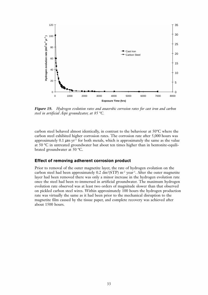
Figure 19 shows the hydrogen evolution rates and the equivalent corrosion rates forcarbon steel and cast iron in Äspö water at 85°C. A comparison of this figure with thedata for 50 °C shows that the increase in temperature caused the initial hydrogen evolu-tion rate to increase by approximately an order of magnitude. However, the cast iron and
33
carbon steel behaved almost identically, in contrast to the behaviour at 50°C where thecarbon steel exhibited higher corrosion rates. The corrosion rate after 5,000 hours wasapproximately 0.1 µm yr-1 for both metals, which is approximately the same as the valueat 50 °C in untreated groundwater but about ten times higher than in bentonite-equili-brated groundwater at 50 °C.
Effect of removing adherent corrosion product
Prior to removal of the outer magnetite layer, the rate of hydrogen evolution on thecarbon steel had been approximately 0.2 dm3(STP) m-2 year-1. After the outer magnetitelayer had been removed there was only a minor increase in the hydrogen evolution rateonce the steel had been re-immersed in artificial groundwater. The maximum hydrogenevolution rate observed was at least two orders of magnitude slower than that observedon pickled carbon steel wires. Within approximately 100 hours the hydrogen productionrate was virtually the same as it had been prior to the mechanical disruption to themagnetite film caused by the tissue paper, and complete recovery was achieved afterabout 1500 hours.
0
20
40
60
80
100
120
0 1000 2000 3000 4000 5000 6000 7000 8000
Exposure Time (hrs)
Hyd
rog
en e
volu
tio
n r
ate
(dm
3 m
-2 y
r-1 )
0
5
10
15
20
25
30
35
Cast IronCarbon SteelSeries3
Figure 19. Hydrogen evolution rates and anaerobic corrosion rates for cast iron and carbonsteel in artificial Äspö groundwater, at 85 °C.

34
35
Electrochemical measurements – atmospheric pressure
Open circuit potential
The equilibrium water reduction potential at pH 8.1 is approximately –720 mV at 25°Cand –760 mV at 50°C. The rest potentials of both the pickled and unpickled specimenswere more negative than the hydrogen reduction potential, by 25 to 55 mV, indicating apotential to generate hydrogen by water reduction, at both temperatures. As the corro-sion product film thickened the potential became more positive. A positive shift in open-circuit potential would cause an increase in the corrosion rate of cathodically-limitedcorrosion, but either a decrease or no change in the corrosion rate of an anodically-limited reaction. The positive shift in the open-circuit potential of the carbon steel whichoccurred as the corrosion product film developed, corresponds to a time during whichthe hydrogen evolution rate on carbon steel was observed to decrease in gas generationexperiments. These observations are consistent with the corrosion process becominganodically-limited by the corrosion product film.
Tafel slopes
The corrosion rates calculated from the Tafel slope measurements for a pickled sample(~23 µm/yr) and a magnetitite-coated sample are in good agreement with the rates calcu-lated from gas evolution measurements during the first 100 hours, but much higher thanthe long-term gas evolution measurements. It is likely that the 74.1 mV dec-1 Tafel slopeobserved with the magnetite-covered specimen was due to the dissolution of Fe2+ ions,but with the process being inhibited by the transport of the cations through the magnet-ite film.
At potentials more positive than –450 mV vs SCE the value of the Tafel slope of themagnetite covered carbon steel specimen began to decrease further, indicating that thepassivity of the magnetite film was increasing. One possible explanation for this behav-iour is the production of hematite:
2Fe3O4 + H2O → 3Fe2O3 + 2H+ + 2e- (5)
the standard potential for which is –0.462 V vs SCE at pH 7.5. There are a number ofalternative Fe(III) compounds which could also have resulted in passivity. Figure 5 showsthat the overall effect of the magnetite film was to reduce the rate of the anodic reaction,i.e. the corrosion reaction was anodically-limited, in agreement with the conclusions fromthe corrosion potential measurements.
The Tafel slope measurements obtained using the film-free static and rotating disc elec-trodes (60 mV dec-1) were in reasonable agreement with the values of other workers(typically between 30 mV dec-1 and 100 mV dec-1).
Discussion
36
The value for the cathodic Tafel slopes were in the region of 50 mV dec-1 (Table 4).This value is significantly below the value of approximately 120 mV dec-1 expected forthe reaction scheme:
H2O + e- ⇒ Hads + OH- (8)
2Hads ⇒ H2 (9)
in which the rate controlling step is step (8). This is thought to be the mechanism forhydrogen evolution on iron in acid solutions. The lower value found in the present workis more consistent with the following reaction scheme:
H2O + e- ⇒ Hads + OH- (10)
Hads + H2O + e- ⇒ H2 + OH- (11)
which gives a cathodic slope of 40 mV dec-1 when the reaction is limited by the surfacecoverage of Hads. The corrosion current, that can be obtained from this data by extrapo-lation of the Tafel lines, has a value of approximately 10-7 A/cm2 which, assuming thecorrosion process is forming ferrous hydroxide, corresponds to a corrosion rate of ap-proximately 1 µm year-1. This is in reasonable agreement with the corrosion rates ob-tained by other workers6 ,7 in relatively short term tests of less than 100 days duration.
ZRA measurements
It is proposed that the corrosion product film consists of an inner oxide overlaid by aporous ferrous hydroxide / ferrous carbonate layer and that the outer portion of thisporous layer exhibits increased levels of transformation to magnetite as the temperatureincreases above 50°C. On this basis three rate controlling steps can be considered:
i. Control of the cathodic reaction by hydrogen concentration at the metal/oxide inter-face and hence by diffusion of hydrogen through the porous oxide layer;
ii. If the phase oxide were continuous, the hydrogen evolution reaction would occur onthe outside of the oxide rather than on the metal and hence the hydrogenoverpotential would be rate limiting;
iii. Control of the anodic reaction by the concentration of ferrous ion.
The ZRA measurements using galvanically coupled platinum and carbon steel electrodeswere carried out to investigate the rate controlling step in the anaerobic corrosion process.
Mechanism (i). If hydrogen diffusion through the oxide were rate controlling, and thestructure of the oxide were as described above, the effect would be for the hydrogenevolution reaction to transfer to the platinum of a platinum-steel couple. As the corrosionprocess proceeded, and the corrosion film thickened, hydrogen evolution on the carbonsteel would be less favoured so more of the hydrogen evolution reaction should transferto the platinum. Therefore the galvanic current flowing through a zero resistance amme-ter (ZRA) connected between the two metals should increase with time. If the porousoxide structure were duplex with a magnetite outer layer, as suggested for temperaturesabove 50°C, the thicker film would result in magnetite depositing within the pores,eventually blocking them. In the extreme this would produce a barrier oxide. Althoughthe initial response recorded on a ZRA may be the same as that below 50°C, with filmformation causing increased transfer of the hydrogen evolution reaction to the platinum,the galvanic current flow between the two electrodes would eventually decay as the oxidecompacted.
37
Mechanism (ii). If the hydrogen over-potential were rate controlling, with the reactionoccurring on the inner oxide, the couple current measured on the ZRA would be thesame for both temperature ranges, at least until the outer layer thickened sufficiently tomake hydrogen diffusion rate limiting.
Mechanism (iii). If the anodic reaction were rate limiting similar behaviour should beobserved in both temperature regimes, since the concentration of ferrous ions and hencethe electrode potential, would remain constant. Therefore the couple current should beconstant, or decrease if hydrogen evolution became rate controlling.
The steady currents found in three of the four experiments conducted at 25°C are there-fore not consistent with hydrogen diffusion through a porous layer being the rate con-trolling step. Instead, the steady currents are more consistent with ferrous ion control(mechanism (iii) above).
Scratching electrode
If an iron or steel electrode is placed into a solution at pH above 8.0, it naturally forms apassivating oxide layer. It is well known that if this oxide layer becomes damaged, it willrapidly reform as long as dissolved oxygen is present in the solution. However, whethersuch a repassivation process can occur in the absence of oxygen depends on the balancebetween the peak repassivation current and the current available from the water reduc-tion reaction. If no passive film forms, the electrode will undergo active dissolution.Whether the carbon steel electrode is active or passive, an oxidising current will berequired. Under open-circuit conditions such a current can only be supplied by thereduction of a solution species, and in the case of a clean aqueous system, oxygen andwater are the only two oxidants available. The scratching electrode experiments in aer-ated conditions show that repassivation occurred rapidly in the presence of oxygen.
At very low levels of dissolved oxygen, the required oxidising current must come fromthe water reduction reaction. This can only occur if the rest potential of the iron or steelspecimen is below the hydrogen evolution potential (-0.712 V vs SCE at pH 8.0). Atsuch low potentials the existence of a stable Fe3O4 film is possible /Pourbaix et al 1974/.The rapid repassivation following the scratching experiment in deaerated conditions(Figure 10a) could be because the cathodic process required for the repassivation of thescratch in the absence of oxygen was partial reduction of the remaining Fe2O3 film on theunscratched part of the electrode surface:
2Fe + 3H2O ⇒ Fe2O3 + 6H+ + 6e- (12)
3Fe2O3 + 9H2O + 6e- ⇒ 6Fe2+ + 18 OH- (13)
This mechanism is consistent with observations from rotating ring disc electrode experi-ments /Sykes et al 1986/ and suggests that Fe2O3 is a good oxidising agent and that itsapparent passivity is predominantly due to the lack of readily available oxidisable species.
After the second scratch (Figure 10b), when repassivation did not appear to occur, itappears that insufficient oxide remained on the electrode surface to regenerate a com-plete Fe2O3 layer over the scratch. The new open-circuit potential was within a fewmillivolts of the hydrogen evolution potential, indicating that only a very small over-potential was required for the water reduction reaction to balance the new anodic processoccurring on the carbon steel electrode. This in turn means that the corrosion processmust have been slow. There was no evidence of any corrosion product on the electrodesurface, indicating that the anaerobic active dissolution process is probably slower than itsaerobic counterpart.
38
In the absence of bicarbonate (Figure 11), the recovery time was much longer than in itspresence, indicating a marginally passivating film on the electrode surface, probably dueto Fe3O4. However, as the final rest potential was approximately ten millivolts below thehydrogen evolution potential, active dissolution was almost certainly still occurring acrossthis film.
Effect of hydrogen overpressure
Corrosion reactions that are cathodically limited by the rate of hydrogen evolutionshould exhibit a correlation between their corrosion potentials and the applied hydrogenoverpressure. This correlation is usually a negative shift in the corrosion potential of 60mV for every decade increase in hydrogen overpressure /Pourbaix et al 1974/, resultingfrom a corresponding shift in the equilibrium potential of the hydrogen reduction reac-tion. No correlation between either the rest potential with hydrogen overpressure wasobserved, indicating that the anaerobic corrosion of carbon steel in 3.5% NaCl is notcathodically limited. As expected the electrochemically derived corrosion rate, expressedas a current density, icorr, was much greater than that estimated from the weight losscoupons in long term immersion tests.
From the data in Table 7 it appears that slightly higher corrosion rates occurred atelevated hydrogen overpressures. This is an unexpected result, as equation (2) predicts adecrease in corrosion rate with increasing hydrogen overpressure. However, the resultswere within the experimental uncertainties, and it can be concluded that the anaerobiccorrosion rates were independent of hydrogen overpressure.
Corrosion product
Reference to the Pourbaix diagram shows that for iron held close to the hydrogen evolu-tion potential in a solution of around pH 8.0 both the formation of an Fe3O4 film andactive dissolution to Fe2+ ions are thermodynamically feasible. As active dissolution pro-ceeds both the concentration of Fe2+ ions and the pH of the solution should increase,making corrosion less thermodynamically favourable, and the corrosion rate should fallwith time.
Hydrogen evolution
In all tests the corrosion rate decreased with increasing exposure time, as the film ofcorrosion product thickened. This suggests that the protective films did not crack as theythickened, since such behaviour would have resulted in bursts of hydrogen production.The hydrogen evolution process on carbon steel in anaerobic groundwaters can be di-vided in two regions, namely short-term and long-term. In the short-term (<1500 hours),the hydrogen evolution rates were initially high, but then rapidly declined. In the long-term the hydrogen evolution rate was virtually constant. This behaviour is similar to thatreported by Kreis /Kreis 1991; Kreis et al 1992/, Simpson /Simpson et al 1988; Simpsonet al 1985; Schenk 1988/ and Grauer /Grauer et al 1991; Grauer 1988/ who showed thatthe corrosion rate in anaerobic, neutral or alkaline conditions falls with time over aperiod of several thousand hours.
39
The literature relating to the corrosion of iron at low potentials contains strong evidencethat Fe(OH)2 and Fe3O4 surface films thicken until their rate of growth is balanced bytheir rate of dissolution at the oxide/electrolyte interface /Davies et al 1980; Bignold et al1981/. In such circumstances, the rate of metal dissolution is determined by the rate ofdiffusion of metal ions from the metal interface. The published work implies that thefilms grow by a ‘high field’ process driven by the potential gradient across the film in thecase of Fe(OH)2, and by diffusion in the case of the electrically conducting Fe3O4. Bothof these processes predict that, in the absence of dissolution, film thickening will decreasewith time to a negligible rate long before the film has thickened to the point at whichspallation might occur.
Degree of immersion
Differences were observed in the initial gas generation rate between specimens that werefully immersed, partially immersed and exposed to water vapour only, but the long-termrates were very similar. Vapour that condensed out on the carbon steel would have had alower pH than the bulk groundwater, as the buffering salts would not have existed in thevapour phase. A lower pH would be expected to produce a higher corrosion rate, as wasobserved in the early stages of the experiments. However, the faster corrosion rate wouldhave led to a more rapid build-up of protective corrosion product, and caused a morerapid decline in corrosion rate. Furthermore, in water vapour it would not have beenpossible for soluble Fe2+ ions to diffuse away from the surface into bulk solution, hencethe surface concentration of ferrous ions would have been higher.
On the partially immersed specimens, there would have been a pH gradient between thecondensed water vapour and the test solution. This could have resulted in a form ofgalvanic coupling, with increased hydrogen production in the low pH water vapourregions and increased magnetite formation in the high pH submerged regions. Themagnetite might be expected to spread slowly up the wires, from the submerged ends,giving rise to the observed gradual decrease in the hydrogen production rate.
Effect of pre-formed film composition
The low corrosion rates measured for material with pre-formed surface films indicatethat the development of corrosion product film caused the decrease in the corrosion ratethat was observed during the first 1500 hours with pickled carbon steel samples. Thefinal equilibrium corrosion rates for all the pre-coated specimens were similar to thepickled samples, although the thin carbonate film did result in a slightly higher value.This suggests that magnetite was more protective than carbonate.
Effect of ferrous ion
The concentration of ferrous ions in solution did not significantly affect the rate ofhydrogen production. One explanation for this is as follows. The corrosion product isbelieved to consist of two layers of magnetite, namely an inner and an outer layer. Theouter layer is formed by precipitation, and therefore its rate of growth would be expectedto depend on the ferrous ion concentration. However, the majority of the corrosionprotection is believed to be provided by the inner film, which forms directly on thesurface of the steel by an electrochemical mechanism without going through a ferrousion intermediate stage. Consequently its development is less likely to be affected by theferrous ion concentration.
40
Effect of radiolysis products
The reduction in the initial corrosion rate of the carbon steel in the presence of ammo-nia can be explained by the increase in pH that the addition would have caused. How-ever, the addition of 3 mM HNO3 should have caused the pH to fall considerably, per-haps down to pH 3, and therefore would be expected to increase the corrosion rate. Onepossible explanation is that the experimental technique was not able to monitor thehydrogen that was evolved in the first 48 hours after the carbon steel was placed in thegroundwater. If the corrosion rate was very high during this period the nitric acid mayhave been completely consumed before any readings could be taken. The lack of anylong-term influence of nitric acid on the corrosion rate of the carbon steel may be due tothe increased solubility of Fe2+ at lower pH values. This would have resulted in the bulkpH of the groundwater rising as the nitric acid corroded the carbon steel by the follow-ing reaction:
Fe + 2H+ → Fe2+ + H2↑ (14)
As the protons were consumed, and the pH rose, the cathodic reaction would havereverted to the reduction of water, which is the dominant reaction for the corrosion ofiron in anaerobic conditions. Calculations show that the nitric acid added to the testsolution would have been consumed with the first day or two of the test. The cathodicreduction of NO3
- to NO2- could also have occurred in competition with the hydrogen
evolution reaction although the low concentration of nitrate means that it is unlikely tohave had any significant long-term effect.
Effect of ionic strength
The long-term hydrogen evolution rate was at least five times faster in high ionic strengthgroundwater than in the dilute groundwaters, but there was no initial burst of corrosionin the high ionic strength water, whereas there was in dilute groundwaters. This suggeststhat the time required to form a thick protective magnetite film was longer in moreconcentrated solutions. This view is supported by the observation that the black film didnot appear to be as coherent in concentrated solutions as in dilute solutions. Possibleexplanations for the higher hydrogen evolution rates in high ionic strength solutions are:
1. Increased competition between the formation of magnetite and other less protectiveiron salts, such as FeCO3 or FeSO4;
2. Increased availability of anions to form more soluble corrosion products, for exampleFeCl2 instead of Fe(OH)2, and hence reduced ability to form a protective magnetitefilm;
3. Incorporation of ions in the magnetite film increasing its conductivity, and possiblyincreasing its effectiveness as a hydrogen electrode;
4. Local buffering of the pH; magnetite is more thermodynamically favoured at high pHs,therefore the protective hard inner film may only form when the pH at the carbonsteel / groundwater interface is significantly higher than the pH of the bulk solution.
5. A decrease in the thickness of the protective hard inner magnetite layer due to localbuffering of the pH. The water reduction reaction will lead to an increase in the pHat the carbon steel/groundwater interface, to a value that will be limited by the buffer-ing capacity of the groundwater. Since the formation of magnetite is more thermody-namically favoured at high pHs, its thickness could decrease as the buffering capacityof the groundwater increases. The buffering capacity of a groundwater is likely toincrease with its ionic strength.
41
6. Increased conductivity may enable more efficient electron transfer to occur betweenthe carbon steel and the water that is reduced to hydrogen, leading to a higher corro-sion rate.
The visual observation that the black magnetite films formed tended to be less coherentin the more concentrated groundwaters tends to support explanation 1.
The ionic strength of groundwater containing 0.1M K2SO4 was approximately threetimes that of the 10-fold ionic strength groundwater, yet the two solutions yielded virtu-ally identical hydrogen evolution rates. This suggests that the dependence of the hydro-gen evolution rate on ionic strength is restricted to a domain below a threshold value,which lies somewhere between that of the standard and 10-fold strength groundwaters.Above this limit, further increases in the ionic strength of the groundwater are not ex-pected to affect the hydrogen evolution process. The similarity between the results fromthe 0.1M K2SO4 and the 10-fold strength groundwaters supports the idea of increasedelectron transfer efficiency in the more conductive solutions. Once sufficient conductivityhas been reached it is likely that the particular electron transfer process involved is nolonger the rate limiting step.
Effect of groundwater composition
The lower rate of hydrogen production on carbon steel in the bentonite-equilibratedgroundwater compared to other groundwaters is probably due to its higher pH, whichwas 10.5, compared to 8 for the Äspö groundwater. The higher pH favours the formationof magnetite over active dissolution and decreases the solubility of Fe2+ ions, leading tomore rapid formation of a protective magnetite film. This supports the suggestion thatthe influence of the ionic strength on the corrosion rate of the carbon steel is due tochanges in the buffering capacity at the carbon steel/solution interface. The long-termhydrogen production rate (> 5000 hours) on carbon steel in bentonite-equilibratedgroundwater was slightly less than that found in dilute groundwaters, but the differencewas within the error limits of the experimental arrangement.
It can be concluded that although high ionic strength groundwaters increase the rate ofhydrogen production on carbon steel, the increase can be offset by increasing the pH.The addition of 0.1M Na2SO4, to bentonite-equilibrated groundwater had no experimen-tally significant effect on the hydrogen evolution rate.
Effect of temperature
The large increase in the initial corrosion rate with increasing temperature is indicativeof an activation-controlled process, which would be expected to follow an Arrheniusrelationship /Boden 1994/ . As the film develops, the corrosion rate becomes determinedby the diffusion of various species through the oxide film, a process which is considerablyless sensitive to increasing temperature. The composition of the corrosion product wouldbe expected to change form ferrous hydroxide at temperatures below 50°C to magnetiteat higher temperatures /Linnenbom 1958/, although the composition was not determinedin this work.
42
Comparison of cast iron with carbon steel
The long-term anaerobic corrosion rate for cast iron in granitic groundwaters at 50°Cwas approximately five times lower than observed with carbon steel. It was lowest in thebentonite-equilibrated groundwater. The differences in corrosion rate between the twomaterials suggest that there must have been subtle differences in the rate controllingsteps involved in the corrosion mechanism. At temperatures above 50°C it is possible thatthe oxide produced in anaerobic conditions grows by outward diffusion of ferrous ionsfrom the metal-oxide interface, which could be affected by small changes in the structureof the oxide film caused by the different composition and microstructure of the substrate.An alternative explanation may be that the oxide film is more adherent to cast iron thanto carbon steel; similar behaviour has been observed in seawater where cast iron corrodestwo to four times more slowly than carbon steel /Kreysa et al 1992/ .
Increasing the temperature from 50 °C to 85 °C caused the short-term (<500 hours)hydrogen evolution rate for both carbon steel and cast iron to increase by an order ofmagnitude, but in the long-term the corrosion rates were similar to that for cast iron at50°C.
Effect of removing adherent corrosion product
The gas generation rate did not increase significantly after removal of the non-adherentcorrosion product, suggesting that the majority of the protection afforded by the magnet-ite film was provided by a hard inner layer. This layer was not significantly damaged byeither the removal of the outer magnetite layer with tissue paper, or any mechanicaldamage arising when the carbon steel was transferred from one reaction vessel to an-other. It can therefore be concluded that minor mechanical disturbance to the magnetitefilm on the inner carbon steel container is unlikely to result in large bursts of hydrogenproduction.
The strongly adhering inner part of the dual layer structure of the magnetite films prob-ably formed directly on the carbon steel by the electrochemical reaction;
3Fe + 4H2O → Fe3O4 + 4H2 (15)
The easily removable layer is likely to have been formed by a precipitation process, such as;
Fe + 2H2O → Fe2+ + H2 + 2OH- (16)
Fe2+ + 2OH- → Fe(OH)2 (17)
3Fe2+ + 4H2O → Fe3O4 + 8H+ + 2e- (18)
A similar explanation has been proposed for the dual layer magnetite structure found onboiler tubes /Shoesmith et al 1981/.
43
The main conclusions from this paper are as follows:
1. Carbon steel undergoes active anaerobic corrosion in artificial Swedish graniticgroundwater, although a magnetite film retards the rate of corrosion. The outerlayer is a loose porous film that is easily disrupted, while the inner layer is adherentand crystalline and forms the main rate-controlling layer.
2. The anaerobic corrosion rate of bare carbon steel at 30°C, 50°C and 85°C is of theorder of 10 to 30 µm year-1 initially, but as an oxide film forms the rate decreases to<0.1 µm year-1. The initial corrosion rate increases with increasing temperature.
3. Hydrogen overpressures up to 100 atmospheres have no significant effect on thecorrosion rate or the corrosion potential. This suggests that the corrosion reaction istherefore anodically limited, rather than cathodically limited.
4. Higher anaerobic corrosion rates occur above an ionic strength threshold.
5. The anaerobic corrosion rate is not limited by the concentration of dissolved ferrousion.
6. The presence of the radiolysis products ammonia and nitric acid do not significantlyaffect the anaerobic corrosion rate.
7. No localised corrosion initiates under anoxic conditions.
8. Welding has no effect on the anaerobic corrosion rate in granitic groundwaters.
9. The long-term anaerobic corrosion rate of cast iron is approximately five timeslower than for carbon steel in the same solution, at 50°C.
10. The long-term anaerobic corrosion rates of both cast iron and carbon steel arelower in groundwaters at higher pH, due to a more stable oxide film.
11. In both aerated and deaerated conditions, physical damage to the surface has only ashort transient effect on the corrosion rate. The rate of film reformation does notdepend on the presence of dissolved oxygen, because the oxygen required to formthe film is provided by direct reaction between bare steel and the water. If a passiveFe2O3 film exists before anoxic conditions develop, the film can undergo a reductionprocess to provide the current required to regenerate a magnetite film.
Conclusions

44
The authors are grateful for the contributions made to this work by S. Byrne,C.C. Naish, N. Platts, A.P. Rance, K.J. Taylor and M.I. Thomas (AEA Technology), andfor financial support provided by SKB (Sweden).
Acknowledgements
45
References
Bignold G J, de Whalley C H, Garbett K, Garnsey R, Woolsey I S, Libaert D Fand Sale R, “Erosion Corrosion of Mild Steel in Ammoniated Water”, Proc 8th Int.Congress on Metallic Corrosion, 1981.
Bockris J O’M, Genshaw M A, Brusic V, Wroblowa H, Electrochim. Acta 16, (1971):p. 1859.
Boden P J, Effect of Concentration, Velocity and Temperature, Chapter 2.1 in Corro-sion, (Butterworth Heinemann, 1994).
Brookins D G, Eh-pH Diagrams for Geochemistry(Berlin New York: Springer-Verlag1988).
Davies D H, Burstein G T, Corrosion 36, (1980): p. 416.
Grauer R, “The Corrosion Behaviour of Carbon Steel in Portland Cement”, NAGRATechnical Report 88-02E, 1988.
Grauer R, Knecht B, Kreis P and Simpson J P, “Hydrogen Evolution from Corrosionof Iron and Steel in Intermediate Level Waste Repositories”, p. 295 in Scientific Basis forNuclear Waste Management XIV, T.A.Abrajano and L.H.Johnson (eds.), 1991.
Grauer R, Knecht B, Kreis P and Simpson J P, Werkstoffe und Korrosion 42, (1991):p. 637.
Greef R, Peat R, Peter L M, Pletcher D and Robinson J, Instrumental Methods inElectrochemistry, (Ellis Horwood, Chichester, 1985), p. 240.
Jelinek J, Neufeld P, Corrosion 38, (1982): p. 98.
Kreis P and Simpson J P, “Hydrogen Gas Generation from the Corrosion of Iron inCementitious Environments”, in Corrosion Problems Related to Nuclear Waste Dis-posal, European Federation of Corrosion Publication number 7, published by Institute ofMaterials, 1992.
Kreis P, “Hydrogen Evolution from Corrosion of Iron and Steel in Low/IntermediateLevel Waste Repositories”, NAGRA Technical Report 91-21, 1991.
Kreysa G and Eckerman R, Dechema Corrosion Handbook, volume 11, Seawater,(Dechema, 1992), p. 192.
Linnenbom V J, J. Electrochem. Soc. 105 (1958): p. 321.
Marsh G P, Taylor K J, Sharland S M, Tasker P W, “An Approach for Evaluatingthe General and Localised Corrosion of Carbon Steel Containers for Nuclear WasteDisposal”, MRS Symposium on Nuclear Waste Management, (Boston, Materials Re-search Society, 1986).
Nomura K, Ujihira Y, J. Mater. Sci. 19 (1984): p. 2664.
46
Pourbaix M, de Soubov N, Atlas of Electrochemical Equilibria in Aqueous Solutions,(Houston, TX: NACE, 1974), p. 307.
Schenk R, “Untersuchungen Uber Die Wasserstoffbildung Durch Eisen KorrosionUnter Endlagerbdingungen”, NAGRA Technical Report 86-24, 1988.
Seo M, Hultquist G, Grasjo L, Sato N, 10th International Congress on MetallicCorrosion, Paper 231 (1986): p. 481.
Shoesmith D W, Rummery T E, Lee Woon, Owen D G, Power Industry Research 1,(1981): p. 43.
Simpson J P and Weber J, “Hydrogen Evolution from Corrosion in Nuclear WasteRepositories”, UK Corrosion ‘88, 1988, p. 33.
Simpson J P, Schenk R and Knecht B, “Corrosion Rate of Unalloyed Steels and CastIrons In Reducing Granitic Groundwaters and Chloride Solutions”, p. 429 in ScientificBasis for Nuclear Waste Management IX, L.Werme (ed.), 1985.
Smellie J A T, Laaksoharju M, Wikberg P, J. Hydrol. 172 (1995): p. 147.
Smellie J A T, Wikberg P, J. Hydrol. 126, (1991): p. 129.
Sykes J M, Riley A M, Mater. Sci. Forum 8, (1986): p. 551.
Turnbull A, Gardner M K, Corros. Sci. 22 (1982): p. 661.
Turnbull A, May A T, Br. Corros. J. 22 (1987): p. 176.