Embed Size (px)
Citation preview
BEFORE THE PUBLIC UTILITIES COMMISSION OF THE
STATE OF CALIFORNIA
In the Matter of the Application of SOUTHERN CALIFORNIA EDISON COMPANY (U 338-E) for a Certificate of Public Convenience and Necessity for the Coolwater-Lugo Transmission Project
)))))
A.13-08-023
(Filed August 28, 2013)
THE AMENDED EXECUTIVE SUMMARY, CHAPTER 1 PURPOSE
AND NEED, AND CHAPTER 3 PROJECT DESCRIPTION
Volume 1 of 1
BETH GAYLORD TAMMY JONES ANGELA WHATLEY Attorneys for SOUTHERN CALIFORNIA EDISON COMPANY
2244 Walnut Grove Avenue Post Office Box 800 Rosemead, California 91770 Telephone: (626) 302-6634 Facsimile: (626) 302-1926 E-mail: [email protected]
Dated: April 25, 2014
THIS AMENDED EXECUTIVE SUMMARY, CHAPTER 1 PURPOSE AND NEED, AND CHAPTER 3 PROJECT DESCRIPTION ARE SEPARATELY FILED AS AN ARCHIVAL DVD
EXECUTIVE SUMMARY
Proponent’s Environmental Assessment Page ES-1 Coolwater-Lugo Transmission Project April 25, 2014
EXECUTIVE SUMMARY
ES.1 Purpose and Need of the Proposed Project
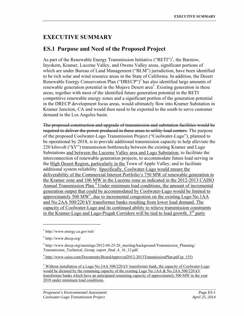
As part of the Renewable Energy Transmission Initiative (“RETI”)1, the Barstow, Inyokern, Kramer, Lucerne Valley, and Owens Valley areas, significant portions of which are under Bureau of Land Management (“BLM”) jurisdiction, have been identified to be rich solar and wind resource areas in the State of California. In addition, the Desert Renewable Energy Conservation Plan (“DRECP”)2 has also identified large amounts of renewable generation potential in the Mojave Desert area3. Existing generation in these areas, together with most of the identified future generation potential in the RETI competitive renewable energy zones and a significant portion of the generation potential in the DRECP development focus areas, would ultimately flow into Kramer Substation in Kramer Junction, CA and would then need to be exported to the south to serve customer demand in the Los Angeles basin.
The proposed construction and upgrade of transmission and substation facilities would be required to deliver the power produced in these areas to utility load centers. The purpose of the proposed Coolwater-Lugo Transmission Project (“Coolwater-Lugo”), planned to be operational by 2018, is to provide additional transmission capacity to help alleviate the 220 kilovolt (“kV”) transmission bottlenecks between the existing Kramer and Lugo Substations and between the Lucerne Valley area and Lugo Substation, to facilitate the interconnection of renewable generation projects, to accommodate future load serving in the High Desert Region, particularly in the Town of Apple Valley, and to facilitate additional system reliability. Specifically, Coolwater-Lugo would ensure the deliverability of the Commercial Interest Portfolio’s 750 MW of renewable generation in the Kramer zone and 106 MW in the Lucerne zone as indicated in the 2012-2013 CAISO Annual Transmission Plan.4 Under minimum load conditions, the amount of incremental generation output that could be accommodated by Coolwater-Lugo would be limited to approximately 500 MW5, due to incremental congestion on the existing Lugo No.1AA and No.2AA 500/220 kV transformer banks resulting from lower load demand. The capacity of Coolwater-Lugo and its continued ability to relieve transmission constraints in the Kramer-Lugo and Lugo-Pisgah Corridors will be tied to load growth, 3rd party
1 http://www.energy.ca.gov/reti/ 2 http://www.drecp.org/ 3 http://www.drecp.org/meetings/2012-04-25-26_meeting/background/Transmission_Planning/ Transmission_Technical_Group_report_final_4_16_12.pdf 4 http://www.caiso.com/Documents/BoardApproved2012-2013TransmissionPlan.pdf (p. 155)
5 Without installation of a Lugo No.3AA 500/220 kV transformer bank, the capacity of Coolwater-Lugo would be dictated by the remaining capacity of the existing Lugo No.1AA & No.2AA 500/220 kV transformer banks which have an anticipated remaining capacity of approximately 500 MW in the year 2018 under minimum load conditions.
EXECUTIVE SUMMARY
Page ES-2 Proponent’s Environmental Assessment April 25, 2014 Coolwater-Lugo Transmission Project
generation projects pursuing development in the Kramer and Lucerne Valley areas, and the specific point of interconnections (POI) of those 3rd party generation projects.
The proposed Coolwater-Lugo scope would consist of installing new transmission lines, new substation facilities to support line termination, and telecommunication facilities to support line protection and the use of a Special Protection System (“SPS”)1. The transmission line would utilize a combination of single-circuit and double-circuit structures consisting of 220 kV and 500 kV design standards between the existing Coolwater Generation Station 220 kV Switchyard (“Coolwater Switchyard”) and the existing CAISO-controlled Lugo Substation, in order to provide an additional path for power to flow from Kramer Substation ultimately to Lugo Substation. Routing of the transmission line south from Coolwater Switchyard through the Lucerne Valley area to Southern California Edison’s (“SCE”) existing transmission ROW, would facilitate future connection to SCE proposed Jasper Substation, which is a separate project that is being developed approximately 22 miles south of Coolwater Switchyard and 27 miles northeast of Lugo Substation. In addition, a new 500/220 kV transformer bank would be installed at Lugo Substation and Aa new Desert View Substation with ultimate design for 500/220/115/12 kV, would be sited and partially constructed approximately 16 miles northeast of Lugo Substation along the proposed transmission line route as part of Coolwater-Lugo in order to consolidate three transmission lines, the new Coolwater-Desert View 220 kV line, and the existing Lugo-Pisgah 220kV #1 and Lugo Pisgah 220kV #2 lines into the existing SCE ROW
As discussed below, and further discussed in Section 1.1 Project Purpose, the purpose of the proposed Coolwater-Lugo is to:
1. Facilitate achievement of the state-mandated Renewables Portfolio Standard (“RPS”) (i.e., 33% renewable by year 2020 per Senate Bill 2 (SBX1 2) in an orderly, rational and cost-effective manner, while also considering the need for maintaining reliable electric service during the upgrade and/or construction of new facilities;
2. Integrate planned renewable generation projects in the Kramer and Lucerne Valley areas and provide for the full delivery of a 250 275 MW renewable generation project, known as the Mojave Solar Project, in a manner which minimizes potential environmental impacts. Currently the 250 275 MW renewable generation project is under construction by Abengoa Solar, Inc. (Abengoa), the interconnection customer, who has executed a Power Purchase Agreement (“PPA”) pursuant to California Public Utilities Commission
1 As defined by the North American Electric Reliability Corporation (NERC), a SPS is an automatic protection system designed to detect abnormal or predetermined system conditions, and take corrective actions other than and/or in addition to the isolation of faulted components to maintain system reliability. Such action may include changes in demand, generation (MW and MVAR), or system configuration to maintain system stability, acceptable voltage, or power flows.
EXECUTIVE SUMMARY
Proponent’s Environmental Assessment Page ES-3 Coolwater-Lugo Transmission Project April 25, 2014
(“CPUC”) tariff. Abengoa is seeking interconnection via the California Independent System Operator (“CAISO”) Interconnection Process;1
3. Interconnect and deliver energy from up to 1,000 MW ensure the deliverability of the Commercial Interest Portfolio’s 750 MW of renewable generation in the Kramer zone and 106 MW in the Lucerne zone as indicated in the 2012-2013 CAISO Annual Transmission Plan2 in a way that complies with all applicable CAISO, North American Electric Reliability Corporation (“NERC”), and Western Electric Coordinating Council (“WECC”) reliability planning criteria, and in a manner that minimizes transmission line crossings;
4. Support the State of California Greenhouse Gas (“GHG”) Reduction Program;
5. Assist the BLM in meeting the Federal Renewable Energy Mandate to develop 10,000 MW of renewable generation on public lands by 2015;3
6. Support SCE’s California Renewable Energy Small Tariff (“CREST”), Renewable Market Adjusting Tariff (Re-MAT), and SCE’s Rule 21 Projects. By expanding transmission capacity south of Kramer, the Coolwater-Lugo would allow an increased number of SCE retail customers to export to the grid power produced from eligible small-scale renewable energy facilities under CREST, Re-MAT, and Rule 21;
7. Support military desire to serve its own load under Rule 21. The Coolwater-Lugo would allow the military facilities in the Kramer Junction and Ridgecrest areas to develop and serve their own load to meet national security goals;
8. Address the City of Ridgecrest’s renewable energy integration concerns by reducing the existing Kramer-Lugo transmission bottleneck and thus allowing increased development of renewable energy projects in the Ridgecrest area, including Rule 21 projects and projects on military facilities;
9. Facilitate serving future load in the High Desert Region which includes the Town of Apple Valley. As load continues to grow in the High Desert Region, Victor Substation will reach its load serving limits thereby requiring a new major load-serving substation;
1 Abengoa, CAISO, and SCE executed a Large Generation Interconnection Agreement (“LGIA”) for SCE to construct the Coolwater-Lugo 220 kV transmission line in order to provide the Mojave Solar Project full capacity deliverability. The FERC on January 28, 2011 accepted the LGIA with an effective date of January 30, 2011. FERC Docket Nos. ER11-2204-000 and ER11-2368-000.
2 http://www.caiso.com/Documents/BoardApproved2012-2013TransmissionPlan.pdf (p. 155)
3 Executive Order 13212, Actions to Expedite Energy-Related Projects, requires federal agencies to expedite review of energy project applications; and the Energy Policy Act of 2005 (Title II, Sec. 211) requires the Department of Interior (“DOI”) to approve at least 10,000 MW of renewable energy on public lands by 2015.
EXECUTIVE SUMMARY
Page ES-4 Proponent’s Environmental Assessment April 25, 2014 Coolwater-Lugo Transmission Project
10. Facilitate reliability improvements in the Lugo-Pisgah Transmission Corridor, at Coolwater 220 kV Substation, and at Lugo Substation. Currently, eight 500 kV transmission lines terminate at Lugo Substation. By developing Coolwater-Lugo, including the Desert View Substation and corresponding telecommunication upgrades, line protection would be upgraded in the Lugo-Pisgah Transmission Corridor, 220 kV switchrack upgrades would occur at Coolwater 220 kV Substation, and future transmission lines could be delooped out of Lugo Substation could be delooped in the future and looped into Desert View Substation thereby improving overall system reliability; and,
11. Meet project purpose and objectives while minimizing potential environmental effects of Coolwater-Lugo. Specific approaches to minimizing potential environmental effects include:
a) Maximizing the use of existing, previously disturbed transmission corridors to minimize potential effects on previously undisturbed land and resources;
b) Selecting site, route, and structure locations with the lowest potential for environmental impacts while still meeting project objectives; and,
c) Selecting a route that minimizes potential environmental impacts and project costs.
One of the major existing bottlenecks that would preclude the transfer of energy produced from renewable resources accumulating at Kramer Substation, is referred to as the Kramer-Lugo transmission corridor. This corridor consists of two 220 kilovolt (“kV”) and two 115 kV transmission lines with limited transfer capability due to existing facility limitations. Specifically, the Kramer-Lugo No.1 and No.2 220 kV transmission lines are currently at thermal capacity under peak system conditions, cannot be upgraded, and have become a transmission bottleneck. A second existing bottleneck that would also preclude the transfer of energy from future renewable resources developing in the Lucerne Valley area, near SCE’s future Jasper Substation, is referred to as the Lugo-Pisgah transmission corridor. Figure ES.1-A depicts a block diagram of the major transmission facilities associated with these two corridors.
EXECUTIVE SUMMARY
Proponent’s Environmental Assessment Page ES-5 Coolwater-Lugo Transmission Project April 25, 2014
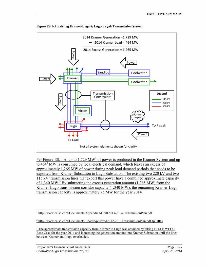
Figure ES.1-A Existing Kramer-Lugo & Lugo-Pisgah Transmission System
Coolwater
Coolwater
Victor
Lugo
TransmissionConstraints
Sandlot
Power
Po
wer
Power
PowerP
ow
er
FutureJasper
To Load
Legend
115 kV
220 kV500 kV
Kramer
2014 Kramer Generation =1,729 MW
2014 Kramer Load = 464 MW
2014 Excess Generation = 1,265 MW
To Pisgah
Not all system elements shown for clarity
Per Figure ES.1-A, up to 1,729 MW1 of power is produced in the Kramer System and up to 4642 MW is consumed by local electrical demand, which leaves an excess of approximately 1,265 MW of power during peak load demand periods that needs to be exported from Kramer Substation to Lugo Substation. The existing two 220 kV and two 115 kV transmission lines that export this power have a combined approximate capacity of 1,340 MW.3 By subtracting the excess generation amount (1,265 MW) from the Kramer-Lugo transmission corridor capacity (1,340 MW), the remaining Kramer-Lugo transmission capacity is approximately 75 MW for the year 2014.
1 http://www.caiso.com/Documents/AppendixADraft2013-2014TransmissionPlan.pdf
2 http://www.caiso.com/Documents/BoardApproved2012-2013TransmissionPlan.pdf (p. 104)
3 The approximate transmission capacity from Kramer to Lugo was obtained by taking a PSLF WECC Base Case for the year 2014 and increasing the generation amount into Kramer Substation until the lines between Kramer and Lugo overloaded.
EXECUTIVE SUMMARY
Page ES-6 Proponent’s Environmental Assessment April 25, 2014 Coolwater-Lugo Transmission Project
On August 22, 2006, Mojave Solar LLC applied to the CAISO for interconnection of the proposed Mojave Solar Project pursuant to Section 3.5 of the Larger Generator Interconnection Procedures issued under the CAISO Tariff. The Queue #125 Mojave Solar Project is a solar thermal generating facility, currently being constructed in Hinkely California, which will interconnect into SCE’s Sandlot1 Substation and ultimately inject 2752 MW into Kramer Substation and exceed the remaining Kramer-Lugo transmission corridor capacity.
ES.2 Project Objectives
The California Environmental Quality Act (“CEQA”) (Pub. Res. Code § 21000, et seq.) and Section 15126.6 (a) of the CEQA Guidelines3 require the consideration of a reasonable range of alternatives to a proposed project, or the location of a proposed project, that would feasibly attain most of the basic objectives of the project but would avoid or substantially lessen any of the significant effects of the project. Section 15126.6 (a) of the CEQA Guidelines also requires that the comparative merits of the alternatives be evaluated. In order to develop a reasonable range of alternatives, Section 15124(b) of the CEQA Guidelines requires that a clearly written statement of objectives be prepared for a proposed project that demonstrates the objectives sought to be achieved by the project and includes the underlying purpose of the project. The range of potential alternatives selected for evaluation shall “include those that could feasibly accomplish most of the basic objectives of the project and could avoid or substantially lessen one or more of the significant effects.”4 In addition to the purposes described above and in Section 1.1, SCE has identified the following objectives for meeting Coolwater-Lugo’s purpose and need described in this chapter:
1. Facilitate SCE and other California utilities achievement of achieving and maintaining California’s Renewable Portfolio Standards in an expedited manner;
2. Provide transmission facilities identified as necessary for the full delivery of a 250 275-megawatt renewable generation project located in the Barstow area, and future generation resources in the Barstow, Inyokern, Kramer, Lucerne Valley/future Jasper Substation, Town of Apple Valley, and Owens Valley areas;
3. Comply with all applicable reliability planning criteria required by the California Independent System Operator, the North American Electric Reliability Corporation, and the Western Electric Coordinating Council;
4. Support California’s GHG Reduction Program;
1 www.sce.com/sandlot
2 The Abengoa Mojave Solar Project consists of a 250 MW interconnection request (Q125) and an incremental 25 MW request (Q909), for a total of 275 MW.
3 See Cal. Code Regs., tit. 14, §15000, et seq. 4 Cal. Code Regs., tit. 14, §15126.6(c).
EXECUTIVE SUMMARY
Proponent’s Environmental Assessment Page ES-7 Coolwater-Lugo Transmission Project April 25, 2014
5. Support Bureau of Land Management (“BLM”) compliance with the Federal Renewable Energy Mandate;
6. Provide transmission facilities in a timely manner that would facilitate the interconnection of eligible small-scale renewable energy facilities California Renewable Energy Small Tariff under SCE’s CREST, Re-MAT, and Rule 21 tariffs projects;
7. Provide transmission facilities that facilitate the Department of Defense meeting their Energy Mandate of producing or procuring 25 percent of their total energy from renewable energy sources beginning in 2025 as outlined under the National Defense Authorization Act of 2010;1
8. Address transmission capacity concerns from the City of Ridgecrest;
9. License a new multipurpose 500/220/115/12 kilovolt (“kV”) Desert View Substation southeast of the Town of Apple Valley to facilitate load serving, reliability, and future generation interconnections;2
10. Construct facilities in an orderly, rational, and cost-effective manner to maintain reliable electric service and by minimizing service interruptions during construction;
11. Minimize potential environmental impacts through selection of transmission routes and substation site locations, including maximizing the use of existing transmission corridors in order to minimize potential effects on previously undisturbed land and resources3, and where existing right-of-ways (“ROWs”) are not available, utilize the shortest route that minimizes potential environmental impacts;
12. Meet project needs in a cost-effective and timely manner; and,
1 See http://www.govenergy.com/2010/Files/Presentations/Renewables/2010_GovEnergy_Tindal.pdf
2 The proposed Desert View Substation would be initially constructed with only the facilities needed to support the transmission line from Coolwater to Lugo. Similar to SCE’s Antelope Substation and Windhub Substation, SCE is seeking to license the full build out of Desert View Substation, which would include 500/220/115/12 kV facilities needed for anticipated load serving in the High Desert Region, particularly the Town of Apple Valley, additional reliability, and future generation interconnections.
3 See Garamendi Principles (Senate Bill 2431, Stats. 1988, Ch. 1457) regarding State transmission siting policies, including; 1) encourage the use of existing rights-of-way by upgrading existing transmission facilities where technically and economically justifiable; 2) when construction of new transmission lines is required, encourage expansion of existing right-of-way, when technically and economically feasible; 3) provide for the creation of new rights-of-way when justified by environmental, technical, or economic reasons as determined by the appropriate licensing agency; 4) where there is a need to construct additional transmission capacity seek agreement among all interested utilities on the efficient use of that capacity.
EXECUTIVE SUMMARY
Page ES-8 Proponent’s Environmental Assessment April 25, 2014 Coolwater-Lugo Transmission Project
13. Design and construct the Project in conformance with SCE's current engineering, design, and construction standards for substation, transmission, subtransmission, and distribution system projects.
ES.3 Summary of Proposed Project
To provide additional south of Kramer capacity to integrate current and future renewable generation projects, SCE needs to develop new and upgraded transmission facilities. These new and upgraded transmission facilities would eliminate the bottlenecks that would preclude renewable generation resources from reaching the utility load centers. To this end, SCE is required to develop and maintain a reliable transmission network with adequate capacity. The facilities needed to deliver the electrical power from the new planned generation resources located in the Barstow, Inyokern, Kramer, Lucerne Valley/future Jasper Substation, and Owens Valley areas have been identified through generation interconnection studies performed as mandated by the CAISO. The major components of these facilities are summarized below with complete descriptions provided in Chapter 3, Project Description.
Substations
▪ Reconfigure Coolwater 220 kV Switchyard
▪ Terminate new Coolwater-Desert View 220 kV Transmission Line at the Coolwater and Desert View 220 kV buses
▪ Install new relay buildings and necessary equipment to support the SPS at Coolwater 220 kV Switchyard
▪ Expand the Lugo 500 kV Switchrack to the south five positions
▪ Relocate two existing 500 kV transmission line terminations at Lugo Substation
▪ Terminate new Desert View-Lugo 220 kV Transmission Line at the Desert View and Lugo 220 kV buses
▪ Install one 500/220 kV transformer bank at Lugo Substation
▪ Construct new relay building and install bank protection relays at Lugo Substation
▪ Install new protection, control, and SPS at Lugo Substation
▪ License proposed Desert View 500/220/115/12 kV Substation and initially construct the facilities necessary to loop the Coolwater-Lugo 220 kV Transmission Line and the Lugo-Pisgah No.1 & No.2 220 kV Transmission Lines into Desert View Substation including new protection, control, and SPS at Desert View Substation.
EXECUTIVE SUMMARY
Proponent’s Environmental Assessment Page ES-9 Coolwater-Lugo Transmission Project April 25, 2014
Transmission and Telecommunication
▪ Remove approximately 29.1 miles of the existing Lugo-Pisgah No.1 220 kV Transmission Line from Lugo Substation northeast to approximately the intersection of Haynes Road and State Route 247 (“SR-247”)
▪ Remove approximately 16.0 miles of the existing Lugo-Pisgah No.2 220 kV Transmission Line from Lugo Substation northeast to proposed Desert View Substation and terminate the remaining portion of this line into the proposed Desert View Substation
▪ Construct 16.6 miles of 500 kV single-circuit transmission line (utilizing 2B-2156 ACSR conductor, replacing the two existing Lugo-Pisgah No.1 and No.2 220 kV Transmission lines,initially operated at 220 kV) from Lugo Substation to the proposed Desert View Substation and 13.6 miles of 220 kV double-circuit transmission line in existing ROW from proposed Desert View Substation to approximately the intersection of Haynes Road and SR-247
▪ Construct approximately 34.0 miles of 220 kV double-circuit transmission line from Coolwater 220 kV Switchyard south to the existing Lugo-Pisgah transmission corridor, located approximately near the intersection of Haynes Road and SR-247
▪ Install a new 150-foot tall microwave tower and foundation at the existing Coolwater 220 kV Switchyard
▪ Install lightwave transponder equipment or optical amplifier and channel bank equipment at Coolwater Switchyard, Lugo Substation, and the proposed Desert View Substation
▪ Install approximately 11.0 miles of Fiber-Optic Cable from existing Apple Valley Substation to the proposed Desert View Substation
▪ Install approximately 29.0 miles of Fiber-Optic Cable from existing Pisgah Substation near Ludlow to the existing Gale Substation near Daggett
ES.4 Alternatives to the Proposed Project
ES.4.1 Overview Alternatives to the Proposed Project were developed and evaluated based on the Project objectives, purpose, and need. As summarized in Section ES.2, the purpose of the proposed Coolwater-Lugo Transmission Project is to help alleviate the 220 kV transmission bottleneck between the existing Kramer and Lugo Substations, to facilitate the interconnection of renewable generation projects, to accommodate future load serving in the High Desert Region, particularly in the Town of Apple Valley, and to facilitate additional system reliability.
EXECUTIVE SUMMARY
Page ES-10 Proponent’s Environmental Assessment April 25, 2014 Coolwater-Lugo Transmission Project
ES.4.2 System Alternatives System alternatives considered and eliminated include: (1) Constructing a Coolwater-Pisgah 220 kV Transmission Line; (2) Rebuilding the Existing Kramer-Lugo 220 kV Transmission Lines; (3) Reconductoring the Existing Kramer-Lugo 220 kV Transmission Lines; (4) Constructing a Kramer-Lugo No.3 220 kV Transmission Line; (5) Constructing a Kramer-Llano 500 kV Transmission Line; (6) Constructing a Kramer-Llano 500 kV Transmission Line and rebuilding of the Lugo-Pisgah No.1 220 kV Transmission Line; (7) The AV Clearview Transmission Proposal – Baseline Case (non-SCE sponsored project); (8) AV Clearview Transmission Proposal – Expanded Case (non-SCE sponsored project); and, (9) No project alternative. System alternatives were eliminated from further consideration (refer to Chapter 1, Purpose & Need, Section 1.4 for detailed information).
ES.4.3 Transmission Route & Substation Site Alternatives Transmission line route alternatives considered include: (Route Alternative A) Exiting the west side of Coolwater Switchyard and continuing south across Interstate 40 (“I-40”) and paralleling the Los Angeles Department of Water and Power transmission corridor to the Lucerne Valley Cutoff, following the Lucerne Valley Cutoff in new ROW to State Route 247 (“SR-247”), following SR-247 south to an existing SCE transmission ROW, using the existing SCE transmission ROW southwest to the proposed Desert View Substation, and continuing southwest in the existing ROW to SCE’s existing Lugo Substation; (Route Alternative B with Segment 9) same as Route Alternative A, except south of I-40 paralleling an existing SCE 115 kV subtransmission line west across the Marine Corps Logistics Base (“MCLB”) Barstow to SR-247, continuing southwest in new ROW adjacent to existing dirt OHV access roads to Lucerne Valley Cutoff, same as Route Alternative A along Lucerne Valley Cutoff to SR-247, then continuing in new ROW along base of Granite Mountains to existing SCE transmission ROW, same as Route Alternative A in existing ROW to the alternative Desert View Substation site, continuing in new ROW south from Desert View to an existing SCE 500 kV transmission corridor, then paralleling the existing corridor to Lugo Substation; and (Route Alternative B with Segment 10) same as Route Alternative B with Segment 9, with only difference being an alternative segment around the MCLB Barstow on the south side in new ROW west to SR-247.
Substation site alternatives considered include: (Site Alternative 1) The enclosed area of the Proposed Desert View Substation would encompass approximately 86.0 acres located in unincorporated San Bernardino County, to the southeast of the Town of Apple Valley and west of Lucerne Valley. The dimensions of the substation would be approximately 2,200 feet by 1,700 feet. The proposed substation site is vacant desert land containing no improvements. Potential utilities available in the area may include electrical, gas, water, and telecommunications; and (Site Alternative 2) The enclosed area of the substation would encompass approximately 82.0 acres located in unincorporated San Bernardino County, to the southeast of the Town of Apple Valley and west of Lucerne Valley. The dimensions of the substation would be approximately 2,090 feet by 1,700 feet.
EXECUTIVE SUMMARY
Proponent’s Environmental Assessment Page ES-11 Coolwater-Lugo Transmission Project April 25, 2014
The alternative substation site is vacant desert land containing a single-family residential home in the southeast corner of the site, which would be demolished prior to construction activities. In addition there are storage containers on the northwest corner of the substation site and in the center of the site, which would need to be removed.
ES.4.4 Proposed Project Transmission Line Route Alternative A and Substation Site Alternative 1 are carried forward as the Proposed Project in this document. Route A was selected because it maximizes the use of existing transmission ROW, is shorter in length, minimizes impacts to off-highway vehicle recreation areas, and avoids the Bendire’s Thrasher and Juniper Flats Areas of Critical Environmental Concern. Substation Site 1 was selected because is located entirely on vacant land and is closer to the existing transmission corridor. Transmission Line Route Alternative B with Segments 9 or 10 is paired with Substation Site Alternative 2 and carried forward as the Alternative Project.
ES.5 Environmental Summary
SCE conducted an environmental impact assessment for Coolwater-Lugo. The impact assessment is discussed in Section 4, Environmental Impact Assessment. The assessment addressed the following environmental topics:
▪ Aesthetics
▪ Agricultural and Forestry Resources
▪ Air Quality
▪ Biological Resources
▪ Cultural and Paleontological Resources
▪ Geology and Soils
▪ Hazards and Hazardous Materials
▪ Hydrology and Water Quality
▪ Land Use and Planning
▪ Mineral Resources
▪ Noise
▪ Socioeconomics, Population and Housing, and Environmental Justice
▪ Public Services
▪ Recreation
EXECUTIVE SUMMARY
Page ES-12 Proponent’s Environmental Assessment April 25, 2014 Coolwater-Lugo Transmission Project
▪ Transportation and Traffic
▪ Utilities and Service Systems
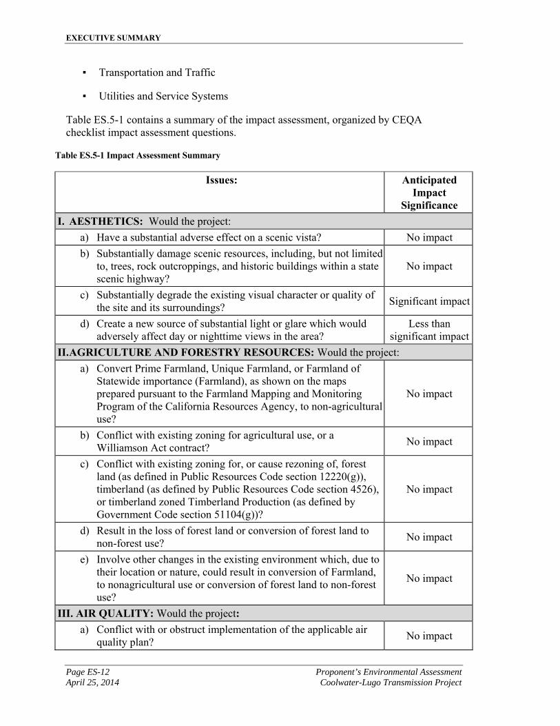
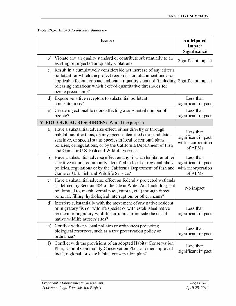
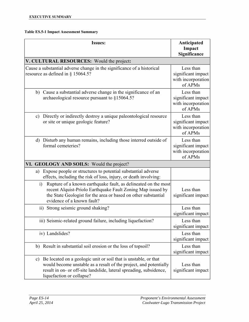
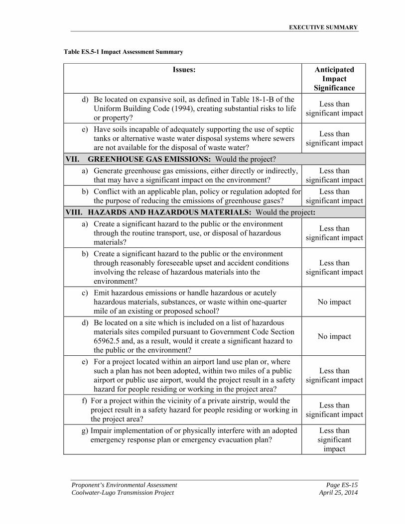
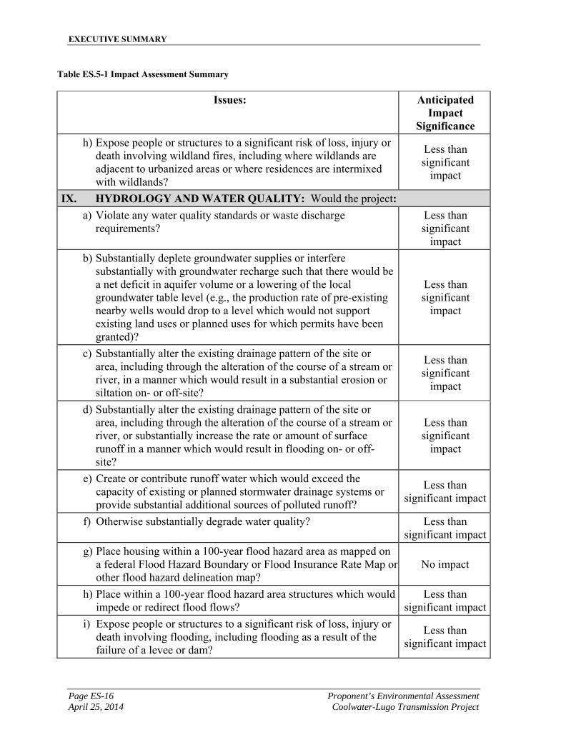
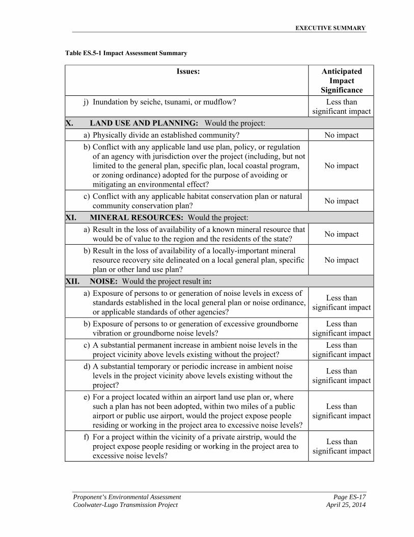
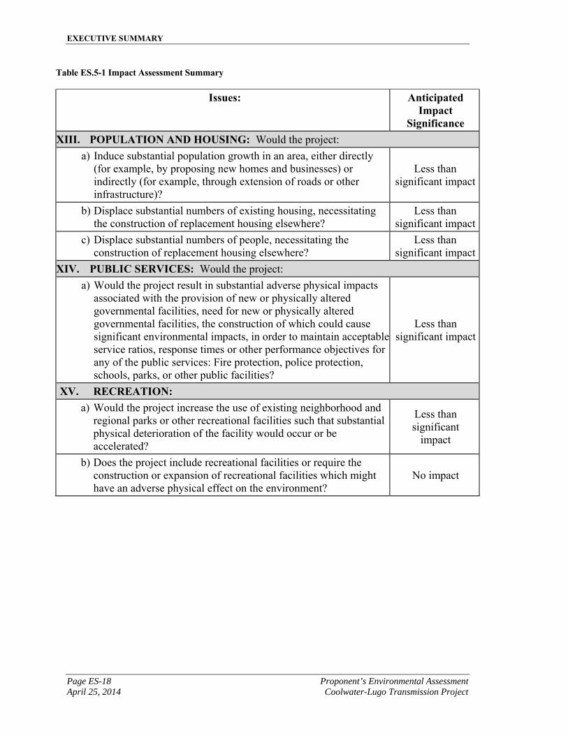
Table ES.5-1 contains a summary of the impact assessment, organized by CEQA checklist impact assessment questions.
Table ES.5-1 Impact Assessment Summary
Issues: Anticipated Impact
Significance I. AESTHETICS: Would the project:
a) Have a substantial adverse effect on a scenic vista? No impact
b) Substantially damage scenic resources, including, but not limited to, trees, rock outcroppings, and historic buildings within a state scenic highway?
No impact
c) Substantially degrade the existing visual character or quality of the site and its surroundings?
Significant impact
d) Create a new source of substantial light or glare which would adversely affect day or nighttime views in the area?
Less than significant impact
II. AGRICULTURE AND FORESTRY RESOURCES: Would the project:
a) Convert Prime Farmland, Unique Farmland, or Farmland of Statewide importance (Farmland), as shown on the maps prepared pursuant to the Farmland Mapping and Monitoring Program of the California Resources Agency, to non-agricultural use?
No impact
b) Conflict with existing zoning for agricultural use, or a Williamson Act contract?
No impact
c) Conflict with existing zoning for, or cause rezoning of, forest land (as defined in Public Resources Code section 12220(g)), timberland (as defined by Public Resources Code section 4526), or timberland zoned Timberland Production (as defined by Government Code section 51104(g))?
No impact
d) Result in the loss of forest land or conversion of forest land to non-forest use?
No impact
e) Involve other changes in the existing environment which, due to their location or nature, could result in conversion of Farmland, to nonagricultural use or conversion of forest land to non-forest use?
No impact
III. AIR QUALITY: Would the project: a) Conflict with or obstruct implementation of the applicable air
quality plan? No impact
EXECUTIVE SUMMARY
Proponent’s Environmental Assessment Page ES-13 Coolwater-Lugo Transmission Project April 25, 2014
Table ES.5-1 Impact Assessment Summary
Issues: Anticipated Impact
Significance b) Violate any air quality standard or contribute substantially to an
existing or projected air quality violation? Significant impact
c) Result in a cumulatively considerable net increase of any criteria pollutant for which the project region is non-attainment under an applicable federal or state ambient air quality standard (including releasing emissions which exceed quantitative thresholds for ozone precursors)?
Significant impact
d) Expose sensitive receptors to substantial pollutant concentrations?
Less than significant impact
e) Create objectionable odors affecting a substantial number of people?
Less than significant impact
IV. BIOLOGICAL RESOURCES: Would the project: a) Have a substantial adverse effect, either directly or through
habitat modifications, on any species identified as a candidate, sensitive, or special status species in local or regional plans, policies, or regulations, or by the California Department of Fish and Game or U.S. Fish and Wildlife Service?
Less than significant impact with incorporation
of APMs
b) Have a substantial adverse effect on any riparian habitat or other sensitive natural community identified in local or regional plans, policies, regulations or by the California Department of Fish and Game or U.S. Fish and Wildlife Service?
Less than significant impact with incorporation
of APMs
c) Have a substantial adverse effect on federally protected wetlands as defined by Section 404 of the Clean Water Act (including, but not limited to, marsh, vernal pool, coastal, etc.) through direct removal, filling, hydrological interruption, or other means?
No impact
d) Interfere substantially with the movement of any native resident or migratory fish or wildlife species or with established native resident or migratory wildlife corridors, or impede the use of native wildlife nursery sites?
Less than significant impact
e) Conflict with any local policies or ordinances protecting biological resources, such as a tree preservation policy or ordinance?
Less than significant impact
f) Conflict with the provisions of an adopted Habitat Conservation Plan, Natural Community Conservation Plan, or other approved local, regional, or state habitat conservation plan?
Less than significant impact
EXECUTIVE SUMMARY
Page ES-14 Proponent’s Environmental Assessment April 25, 2014 Coolwater-Lugo Transmission Project
Table ES.5-1 Impact Assessment Summary
Issues: Anticipated Impact
Significance V. CULTURAL RESOURCES: Would the project: Cause a substantial adverse change in the significance of a historical resource as defined in § 15064.5?
Less than significant impact with incorporation
of APMs
b) Cause a substantial adverse change in the significance of an archaeological resource pursuant to §15064.5?
Less than significant impact with incorporation
of APMs
c) Directly or indirectly destroy a unique paleontological resource or site or unique geologic feature?
Less than significant impact with incorporation
of APMs
d) Disturb any human remains, including those interred outside of formal cemeteries?
Less than significant impact with incorporation
of APMs
VI. GEOLOGY AND SOILS: Would the project?
a) Expose people or structures to potential substantial adverse effects, including the risk of loss, injury, or death involving:
i) Rupture of a known earthquake fault, as delineated on the most recent Alquist-Priolo Earthquake Fault Zoning Map issued by the State Geologist for the area or based on other substantial evidence of a known fault?
Less than significant impact
ii) Strong seismic ground shaking? Less than significant impact
iii) Seismic-related ground failure, including liquefaction? Less than significant impact
iv) Landslides? Less than significant impact
b) Result in substantial soil erosion or the loss of topsoil? Less than significant impact
c) Be located on a geologic unit or soil that is unstable, or that would become unstable as a result of the project, and potentially result in on- or off-site landslide, lateral spreading, subsidence, liquefaction or collapse?
Less than significant impact
EXECUTIVE SUMMARY
Proponent’s Environmental Assessment Page ES-15 Coolwater-Lugo Transmission Project April 25, 2014
Table ES.5-1 Impact Assessment Summary
Issues: Anticipated Impact
Significance d) Be located on expansive soil, as defined in Table 18-1-B of the
Uniform Building Code (1994), creating substantial risks to life or property?
Less than significant impact
e) Have soils incapable of adequately supporting the use of septic tanks or alternative waste water disposal systems where sewers are not available for the disposal of waste water?
Less than significant impact
VII. GREENHOUSE GAS EMISSIONS: Would the project?
a) Generate greenhouse gas emissions, either directly or indirectly, that may have a significant impact on the environment?
Less than significant impact
b) Conflict with an applicable plan, policy or regulation adopted for the purpose of reducing the emissions of greenhouse gases?
Less than significant impact
VIII. HAZARDS AND HAZARDOUS MATERIALS: Would the project: a) Create a significant hazard to the public or the environment
through the routine transport, use, or disposal of hazardous materials?
Less than significant impact
b) Create a significant hazard to the public or the environment through reasonably foreseeable upset and accident conditions involving the release of hazardous materials into the environment?
Less than significant impact
c) Emit hazardous emissions or handle hazardous or acutely hazardous materials, substances, or waste within one-quarter mile of an existing or proposed school?
No impact
d) Be located on a site which is included on a list of hazardous materials sites compiled pursuant to Government Code Section 65962.5 and, as a result, would it create a significant hazard to the public or the environment?
No impact
e) For a project located within an airport land use plan or, where such a plan has not been adopted, within two miles of a public airport or public use airport, would the project result in a safety hazard for people residing or working in the project area?
Less than significant impact
f) For a project within the vicinity of a private airstrip, would the project result in a safety hazard for people residing or working in the project area?
Less than significant impact
g) Impair implementation of or physically interfere with an adopted emergency response plan or emergency evacuation plan?
Less than significant
impact
EXECUTIVE SUMMARY
Page ES-16 Proponent’s Environmental Assessment April 25, 2014 Coolwater-Lugo Transmission Project
Table ES.5-1 Impact Assessment Summary
Issues: Anticipated Impact
Significance h) Expose people or structures to a significant risk of loss, injury or
death involving wildland fires, including where wildlands are adjacent to urbanized areas or where residences are intermixed with wildlands?
Less than significant
impact
IX. HYDROLOGY AND WATER QUALITY: Would the project: a) Violate any water quality standards or waste discharge
requirements? Less than significant
impact
b) Substantially deplete groundwater supplies or interfere substantially with groundwater recharge such that there would be a net deficit in aquifer volume or a lowering of the local groundwater table level (e.g., the production rate of pre-existing nearby wells would drop to a level which would not support existing land uses or planned uses for which permits have been granted)?
Less than significant
impact
c) Substantially alter the existing drainage pattern of the site or area, including through the alteration of the course of a stream or river, in a manner which would result in a substantial erosion or siltation on- or off-site?
Less than significant
impact
d) Substantially alter the existing drainage pattern of the site or area, including through the alteration of the course of a stream or river, or substantially increase the rate or amount of surface runoff in a manner which would result in flooding on- or off-site?
Less than significant
impact
e) Create or contribute runoff water which would exceed the capacity of existing or planned stormwater drainage systems or provide substantial additional sources of polluted runoff?
Less than significant impact
f) Otherwise substantially degrade water quality? Less than significant impact
g) Place housing within a 100-year flood hazard area as mapped on a federal Flood Hazard Boundary or Flood Insurance Rate Map or other flood hazard delineation map?
No impact
h) Place within a 100-year flood hazard area structures which would impede or redirect flood flows?
Less than significant impact
i) Expose people or structures to a significant risk of loss, injury or death involving flooding, including flooding as a result of the failure of a levee or dam?
Less than significant impact
EXECUTIVE SUMMARY
Proponent’s Environmental Assessment Page ES-17 Coolwater-Lugo Transmission Project April 25, 2014
Table ES.5-1 Impact Assessment Summary
Issues: Anticipated Impact
Significance j) Inundation by seiche, tsunami, or mudflow? Less than
significant impact
X. LAND USE AND PLANNING: Would the project:
a) Physically divide an established community? No impact
b) Conflict with any applicable land use plan, policy, or regulation of an agency with jurisdiction over the project (including, but not limited to the general plan, specific plan, local coastal program, or zoning ordinance) adopted for the purpose of avoiding or mitigating an environmental effect?
No impact
c) Conflict with any applicable habitat conservation plan or natural community conservation plan?
No impact
XI. MINERAL RESOURCES: Would the project:
a) Result in the loss of availability of a known mineral resource that would be of value to the region and the residents of the state?
No impact
b) Result in the loss of availability of a locally-important mineral resource recovery site delineated on a local general plan, specific plan or other land use plan?
No impact
XII. NOISE: Would the project result in: a) Exposure of persons to or generation of noise levels in excess of
standards established in the local general plan or noise ordinance, or applicable standards of other agencies?
Less than significant impact
b) Exposure of persons to or generation of excessive groundborne vibration or groundborne noise levels?
Less than significant impact
c) A substantial permanent increase in ambient noise levels in the project vicinity above levels existing without the project?
Less than significant impact
d) A substantial temporary or periodic increase in ambient noise levels in the project vicinity above levels existing without the project?
Less than significant impact
e) For a project located within an airport land use plan or, where such a plan has not been adopted, within two miles of a public airport or public use airport, would the project expose people residing or working in the project area to excessive noise levels?
Less than significant impact
f) For a project within the vicinity of a private airstrip, would the project expose people residing or working in the project area to excessive noise levels?
Less than significant impact
EXECUTIVE SUMMARY
Page ES-18 Proponent’s Environmental Assessment April 25, 2014 Coolwater-Lugo Transmission Project
Table ES.5-1 Impact Assessment Summary
Issues: Anticipated Impact
Significance XIII. POPULATION AND HOUSING: Would the project:
a) Induce substantial population growth in an area, either directly (for example, by proposing new homes and businesses) or indirectly (for example, through extension of roads or other infrastructure)?
Less than significant impact
b) Displace substantial numbers of existing housing, necessitating the construction of replacement housing elsewhere?
Less than significant impact
c) Displace substantial numbers of people, necessitating the construction of replacement housing elsewhere?
Less than significant impact
XIV. PUBLIC SERVICES: Would the project:
a) Would the project result in substantial adverse physical impacts associated with the provision of new or physically altered governmental facilities, need for new or physically altered governmental facilities, the construction of which could cause significant environmental impacts, in order to maintain acceptable service ratios, response times or other performance objectives for any of the public services: Fire protection, police protection, schools, parks, or other public facilities?
Less than significant impact
XV. RECREATION: a) Would the project increase the use of existing neighborhood and
regional parks or other recreational facilities such that substantial physical deterioration of the facility would occur or be accelerated?
Less than significant
impact
b) Does the project include recreational facilities or require the construction or expansion of recreational facilities which might have an adverse physical effect on the environment?
No impact
EXECUTIVE SUMMARY
Proponent’s Environmental Assessment Page ES-19 Coolwater-Lugo Transmission Project April 25, 2014
Table ES.5-1 Impact Assessment Summary
Issues: Anticipated Impact
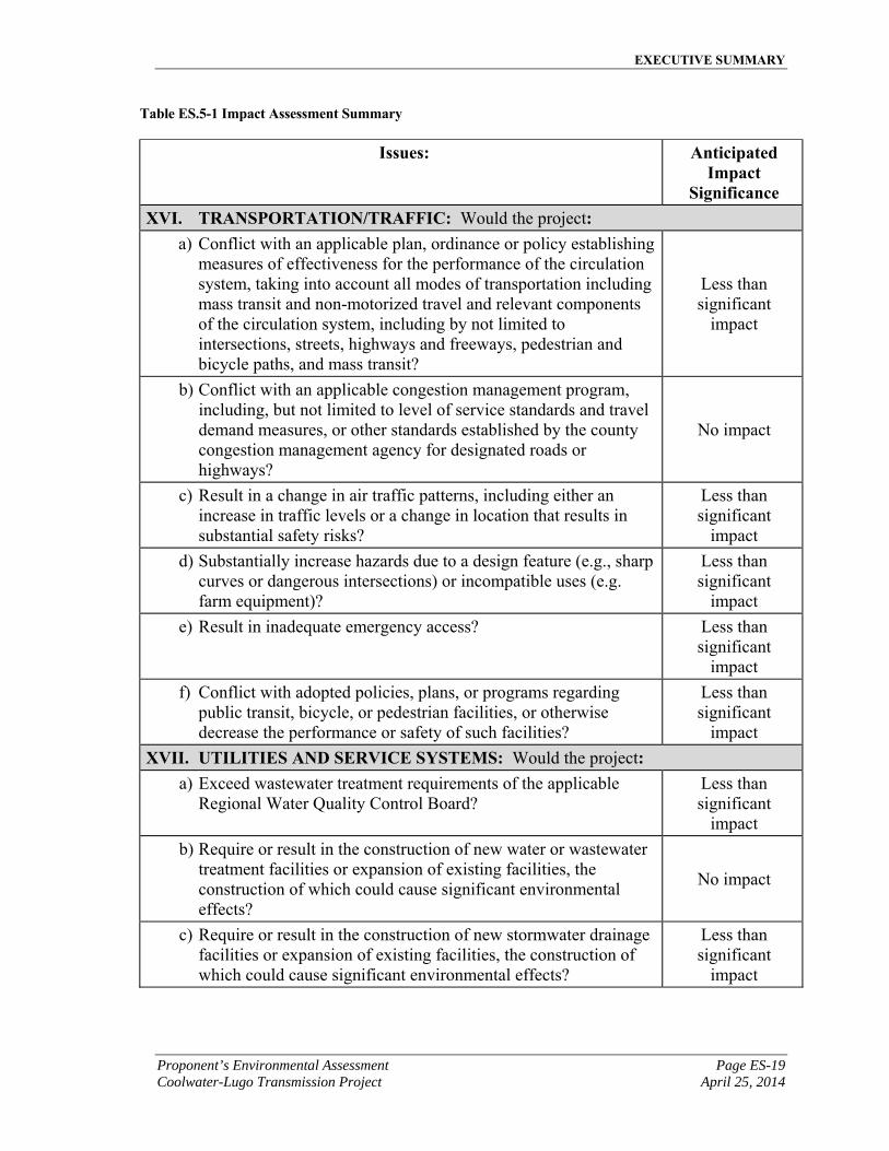
Significance XVI. TRANSPORTATION/TRAFFIC: Would the project:
a) Conflict with an applicable plan, ordinance or policy establishing measures of effectiveness for the performance of the circulation system, taking into account all modes of transportation including mass transit and non-motorized travel and relevant components of the circulation system, including by not limited to intersections, streets, highways and freeways, pedestrian and bicycle paths, and mass transit?
Less than significant
impact
b) Conflict with an applicable congestion management program, including, but not limited to level of service standards and travel demand measures, or other standards established by the county congestion management agency for designated roads or highways?
No impact
c) Result in a change in air traffic patterns, including either an increase in traffic levels or a change in location that results in substantial safety risks?
Less than significant
impact
d) Substantially increase hazards due to a design feature (e.g., sharp curves or dangerous intersections) or incompatible uses (e.g. farm equipment)?
Less than significant
impact
e) Result in inadequate emergency access? Less than significant
impact
f) Conflict with adopted policies, plans, or programs regarding public transit, bicycle, or pedestrian facilities, or otherwise decrease the performance or safety of such facilities?
Less than significant
impact
XVII. UTILITIES AND SERVICE SYSTEMS: Would the project: a) Exceed wastewater treatment requirements of the applicable
Regional Water Quality Control Board? Less than significant
impact
b) Require or result in the construction of new water or wastewater treatment facilities or expansion of existing facilities, the construction of which could cause significant environmental effects?
No impact
c) Require or result in the construction of new stormwater drainage facilities or expansion of existing facilities, the construction of which could cause significant environmental effects?
Less than significant
impact
EXECUTIVE SUMMARY
Page ES-20 Proponent’s Environmental Assessment April 25, 2014 Coolwater-Lugo Transmission Project
Table ES.5-1 Impact Assessment Summary
Issues: Anticipated Impact
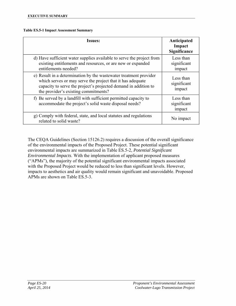
Significance d) Have sufficient water supplies available to serve the project from
existing entitlements and resources, or are new or expanded entitlements needed?
Less than significant
impact
e) Result in a determination by the wastewater treatment provider which serves or may serve the project that it has adequate capacity to serve the project’s projected demand in addition to the provider’s existing commitments?
Less than significant
impact
f) Be served by a landfill with sufficient permitted capacity to accommodate the project’s solid waste disposal needs?
Less than significant
impact
g) Comply with federal, state, and local statutes and regulations related to solid waste?
No impact
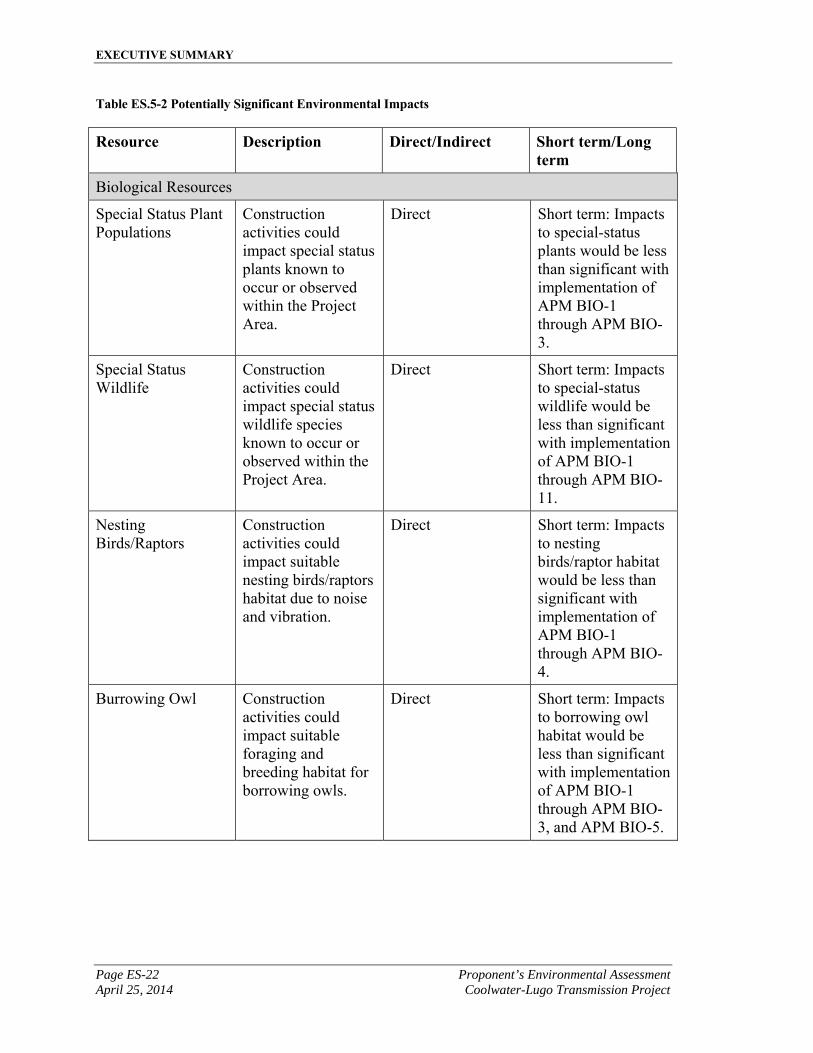
The CEQA Guidelines (Section 15126.2) requires a discussion of the overall significance of the environmental impacts of the Proposed Project. These potential significant environmental impacts are summarized in Table ES.5-2, Potential Significant Environmental Impacts. With the implementation of applicant proposed measures (“APMs”), the majority of the potential significant environmental impacts associated with the Proposed Project would be reduced to less than significant levels. However, impacts to aesthetics and air quality would remain significant and unavoidable. Proposed APMs are shown on Table ES.5-3.
EXECUTIVE SUMMARY
Proponent’s Environmental Assessment Page ES-21 Coolwater-Lugo Transmission Project April 25, 2014
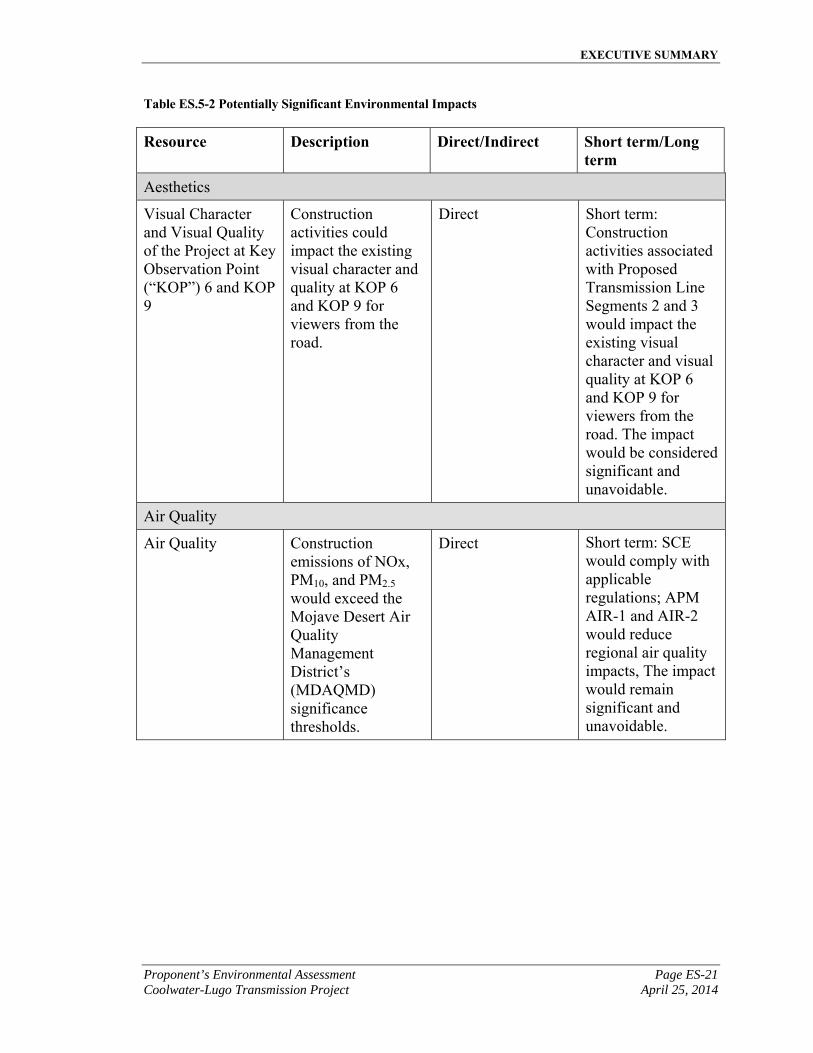
Table ES.5-2 Potentially Significant Environmental Impacts
Resource Description Direct/Indirect Short term/Long term
Aesthetics
Visual Character and Visual Quality of the Project at Key Observation Point (“KOP”) 6 and KOP 9
Construction activities could impact the existing visual character and quality at KOP 6 and KOP 9 for viewers from the road.
Direct Short term: Construction activities associated with Proposed Transmission Line Segments 2 and 3 would impact the existing visual character and visual quality at KOP 6 and KOP 9 for viewers from the road. The impact would be considered significant and unavoidable.
Air Quality
Air Quality Construction emissions of NOx, PM10, and PM2.5
would exceed the Mojave Desert Air Quality Management District’s (MDAQMD) significance thresholds.
Direct Short term: SCE would comply with applicable regulations; APM AIR-1 and AIR-2 would reduce regional air quality impacts, The impact would remain significant and unavoidable.
EXECUTIVE SUMMARY
Page ES-22 Proponent’s Environmental Assessment April 25, 2014 Coolwater-Lugo Transmission Project
Table ES.5-2 Potentially Significant Environmental Impacts
Resource Description Direct/Indirect Short term/Long term
Biological Resources
Special Status Plant Populations
Construction activities could impact special status plants known to occur or observed within the Project Area.
Direct Short term: Impacts to special-status plants would be less than significant with implementation of APM BIO-1 through APM BIO-3.
Special Status Wildlife
Construction activities could impact special status wildlife species known to occur or observed within the Project Area.
Direct Short term: Impacts to special-status wildlife would be less than significant with implementation of APM BIO-1 through APM BIO-11.
Nesting Birds/Raptors
Construction activities could impact suitable nesting birds/raptors habitat due to noise and vibration.
Direct Short term: Impacts to nesting birds/raptor habitat would be less than significant with implementation of APM BIO-1 through APM BIO-4.
Burrowing Owl Construction activities could impact suitable foraging and breeding habitat for borrowing owls.
Direct Short term: Impacts to borrowing owl habitat would be less than significant with implementation of APM BIO-1 through APM BIO-3, and APM BIO-5.
EXECUTIVE SUMMARY
Proponent’s Environmental Assessment Page ES-23 Coolwater-Lugo Transmission Project April 25, 2014
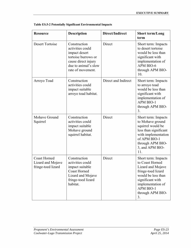
Table ES.5-2 Potentially Significant Environmental Impacts
Resource Description Direct/Indirect Short term/Long term
Desert Tortoise Construction activities could impact desert tortoise burrows or cause direct injury due to animal’s slow rate of movement.
Direct Short term: Impacts to desert tortoise would be less than significant with implementation of APM BIO-6 through APM BIO-10.
Arroyo Toad Construction activities could impact suitable arroyo toad habitat.
Direct and Indirect Short term: Impacts to arroyo toad would be less than significant with implementation of APM BIO-1 through APM BIO-3.
Mohave Ground Squirrel
Construction activities could impact suitable Mohave ground squirrel habitat.
Direct Short term: Impacts to Mohave ground squirrel would be less than significant with implementation of APM BIO-1 through APM BIO-3, and APM BIO-11.
Coast Horned Lizard and Mojave fringe-toed lizard
Construction activities could impact suitable Coast Horned Lizard and Mojave fringe-toed lizard habitat.
Direct Short term: Impacts to Coast Horned Lizard and Mojave fringe-toed lizard would be less than significant with implementation of APM BIO-1 through APM BIO-3.
EXECUTIVE SUMMARY
Page ES-24 Proponent’s Environmental Assessment April 25, 2014 Coolwater-Lugo Transmission Project
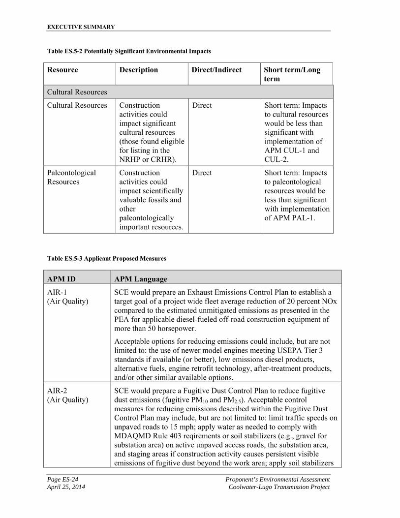
Table ES.5-2 Potentially Significant Environmental Impacts
Resource Description Direct/Indirect Short term/Long term
Cultural Resources
Cultural Resources Construction activities could impact significant cultural resources (those found eligible for listing in the NRHP or CRHR).
Direct Short term: Impacts to cultural resources would be less than significant with implementation of APM CUL-1 and CUL-2.
Paleontological Resources
Construction activities could impact scientifically valuable fossils and other paleontologically important resources.
Direct Short term: Impacts to paleontological resources would be less than significant with implementation of APM PAL-1.
Table ES.5-3 Applicant Proposed Measures
APM ID APM Language
AIR-1 (Air Quality)
SCE would prepare an Exhaust Emissions Control Plan to establish a target goal of a project wide fleet average reduction of 20 percent NOx compared to the estimated unmitigated emissions as presented in the PEA for applicable diesel-fueled off-road construction equipment of more than 50 horsepower.
Acceptable options for reducing emissions could include, but are not limited to: the use of newer model engines meeting USEPA Tier 3 standards if available (or better), low emissions diesel products, alternative fuels, engine retrofit technology, after-treatment products, and/or other similar available options.
AIR-2 (Air Quality)
SCE would prepare a Fugitive Dust Control Plan to reduce fugitive dust emissions (fugitive PM10 and PM2.5). Acceptable control measures for reducing emissions described within the Fugitive Dust Control Plan may include, but are not limited to: limit traffic speeds on unpaved roads to 15 mph; apply water as needed to comply with MDAQMD Rule 403 reqirements or soil stabilizers (e.g., gravel for substation area) on active unpaved access roads, the substation area, and staging areas if construction activity causes persistent visible emissions of fugitive dust beyond the work area; apply soil stabilizers
EXECUTIVE SUMMARY
Proponent’s Environmental Assessment Page ES-25 Coolwater-Lugo Transmission Project April 25, 2014
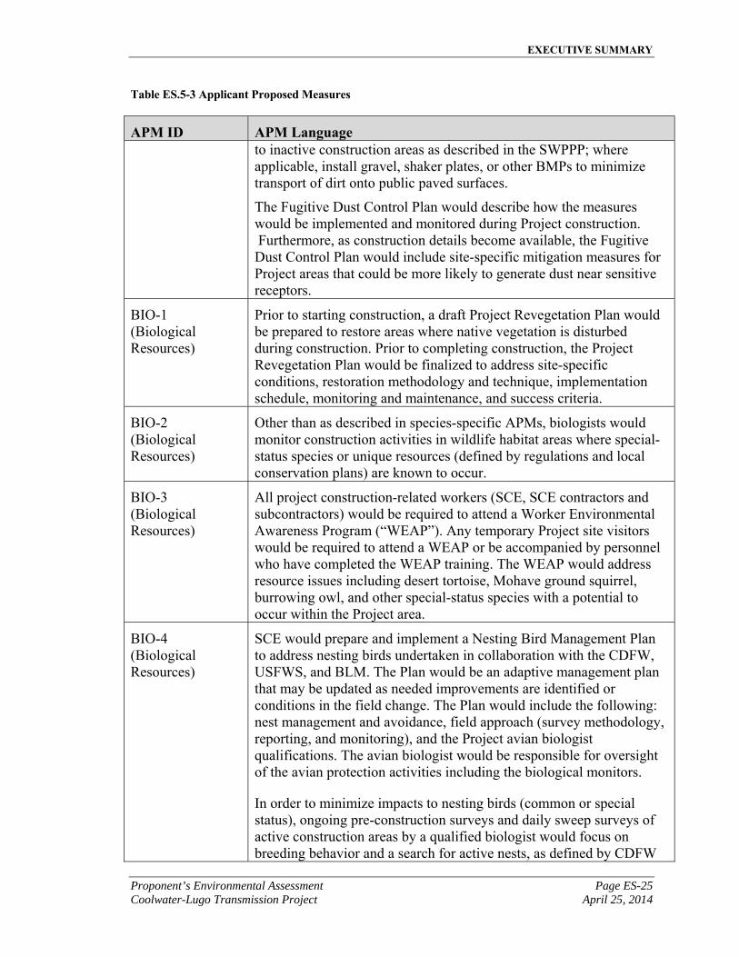
Table ES.5-3 Applicant Proposed Measures
APM ID APM Language to inactive construction areas as described in the SWPPP; where applicable, install gravel, shaker plates, or other BMPs to minimize transport of dirt onto public paved surfaces.
The Fugitive Dust Control Plan would describe how the measures would be implemented and monitored during Project construction. Furthermore, as construction details become available, the Fugitive Dust Control Plan would include site-specific mitigation measures for Project areas that could be more likely to generate dust near sensitive receptors.
BIO-1 (Biological Resources)
Prior to starting construction, a draft Project Revegetation Plan would be prepared to restore areas where native vegetation is disturbed during construction. Prior to completing construction, the Project Revegetation Plan would be finalized to address site-specific conditions, restoration methodology and technique, implementation schedule, monitoring and maintenance, and success criteria.
BIO-2 (Biological Resources)
Other than as described in species-specific APMs, biologists would monitor construction activities in wildlife habitat areas where special-status species or unique resources (defined by regulations and local conservation plans) are known to occur.
BIO-3 (Biological Resources)
All project construction-related workers (SCE, SCE contractors and subcontractors) would be required to attend a Worker Environmental Awareness Program (“WEAP”). Any temporary Project site visitors would be required to attend a WEAP or be accompanied by personnel who have completed the WEAP training. The WEAP would address resource issues including desert tortoise, Mohave ground squirrel, burrowing owl, and other special-status species with a potential to occur within the Project area.
BIO-4 (Biological Resources)
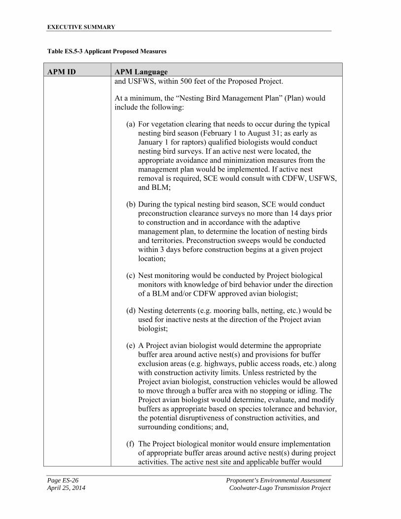
SCE would prepare and implement a Nesting Bird Management Plan to address nesting birds undertaken in collaboration with the CDFW, USFWS, and BLM. The Plan would be an adaptive management plan that may be updated as needed improvements are identified or conditions in the field change. The Plan would include the following: nest management and avoidance, field approach (survey methodology, reporting, and monitoring), and the Project avian biologist qualifications. The avian biologist would be responsible for oversight of the avian protection activities including the biological monitors.
In order to minimize impacts to nesting birds (common or special status), ongoing pre-construction surveys and daily sweep surveys of active construction areas by a qualified biologist would focus on breeding behavior and a search for active nests, as defined by CDFW
EXECUTIVE SUMMARY
Page ES-26 Proponent’s Environmental Assessment April 25, 2014 Coolwater-Lugo Transmission Project
Table ES.5-3 Applicant Proposed Measures
APM ID APM Language and USFWS, within 500 feet of the Proposed Project.
At a minimum, the “Nesting Bird Management Plan” (Plan) would include the following:
(a) For vegetation clearing that needs to occur during the typical nesting bird season (February 1 to August 31; as early as January 1 for raptors) qualified biologists would conduct nesting bird surveys. If an active nest were located, the appropriate avoidance and minimization measures from the management plan would be implemented. If active nest removal is required, SCE would consult with CDFW, USFWS, and BLM;
(b) During the typical nesting bird season, SCE would conduct preconstruction clearance surveys no more than 14 days prior to construction and in accordance with the adaptive management plan, to determine the location of nesting birds and territories. Preconstruction sweeps would be conducted within 3 days before construction begins at a given project location;
(c) Nest monitoring would be conducted by Project biological monitors with knowledge of bird behavior under the direction of a BLM and/or CDFW approved avian biologist;
(d) Nesting deterrents (e.g. mooring balls, netting, etc.) would be used for inactive nests at the direction of the Project avian biologist;
(e) A Project avian biologist would determine the appropriate buffer area around active nest(s) and provisions for buffer exclusion areas (e.g. highways, public access roads, etc.) along with construction activity limits. Unless restricted by the Project avian biologist, construction vehicles would be allowed to move through a buffer area with no stopping or idling. The Project avian biologist would determine, evaluate, and modify buffers as appropriate based on species tolerance and behavior, the potential disruptiveness of construction activities, and surrounding conditions; and,
(f) The Project biological monitor would ensure implementation of appropriate buffer areas around active nest(s) during project activities. The active nest site and applicable buffer would
EXECUTIVE SUMMARY
Proponent’s Environmental Assessment Page ES-27 Coolwater-Lugo Transmission Project April 25, 2014
Table ES.5-3 Applicant Proposed Measures
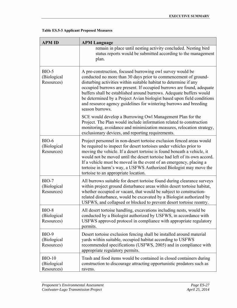
APM ID APM Language remain in place until nesting activity concluded. Nesting bird status reports would be submitted according to the management plan.
BIO-5 (Biological Resources)
A pre-construction, focused burrowing owl survey would be conducted no more than 30 days prior to commencement of ground-disturbing activities within suitable habitat to determine if any occupied burrows are present. If occupied burrows are found, adequate buffers shall be established around burrows. Adequate buffers would be determined by a Project Avian biologist based upon field conditions and resource agency guidelines for wintering burrows and breeding season burrows.
SCE would develop a Burrowing Owl Management Plan for the Project. The Plan would include information related to construction monitoring, avoidance and minimization measures, relocation strategy, exclusionary devices, and reporting requirements.
BIO-6 (Biological Resources)
Project personnel in non-desert tortoise exclusion fenced areas would be required to inspect for desert tortoises under vehicles prior to moving the vehicle. If a desert tortoise is found beneath a vehicle, it would not be moved until the desert tortoise had left of its own accord. If a vehicle must be moved in the event of an emergency, placing a tortoise in harm’s way, a USFWS Authorized Biologist may move the tortoise to an appropriate location.
BIO-7 (Biological Resources)
All burrows suitable for desert tortoise found during clearance surveys within project ground disturbance areas within desert tortoise habitat, whether occupied or vacant, that would be subject to construction-related disturbance, would be excavated by a Biologist authorized by USFWS, and collapsed or blocked to prevent desert tortoise reentry.
BIO-8 (Biological Resources)
All desert tortoise handling, excavations including nests, would be conducted by a Biologist authorized by USFWS, in accordance with USFWS approved protocol in compliance with appropriate regulatory permits.
BIO-9 (Biological Resources)
Desert tortoise exclusion fencing shall be installed around material yards within suitable, occupied habitat according to USFWS recommended specifications (USFWS, 2005) and in compliance with appropriate regulatory permits.
BIO-10 (Biological Resources)
Trash and food items would be contained in closed containers during construction to discourage attracting opportunistic predators such as ravens.
EXECUTIVE SUMMARY
Page ES-28 Proponent’s Environmental Assessment April 25, 2014 Coolwater-Lugo Transmission Project
Table ES.5-3 Applicant Proposed Measures
APM ID APM Language
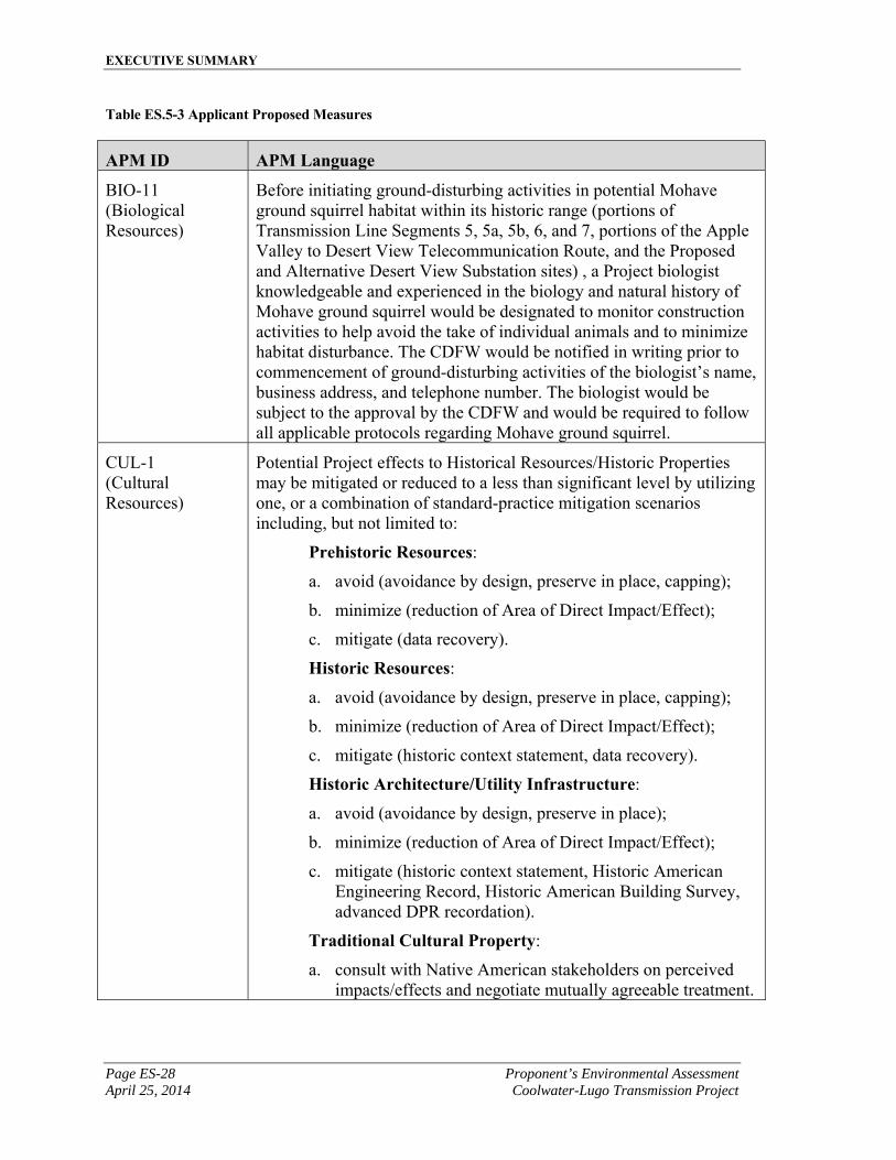
BIO-11 (Biological Resources)
Before initiating ground-disturbing activities in potential Mohave ground squirrel habitat within its historic range (portions of Transmission Line Segments 5, 5a, 5b, 6, and 7, portions of the Apple Valley to Desert View Telecommunication Route, and the Proposed and Alternative Desert View Substation sites) , a Project biologist knowledgeable and experienced in the biology and natural history of Mohave ground squirrel would be designated to monitor construction activities to help avoid the take of individual animals and to minimize habitat disturbance. The CDFW would be notified in writing prior to commencement of ground-disturbing activities of the biologist’s name, business address, and telephone number. The biologist would be subject to the approval by the CDFW and would be required to follow all applicable protocols regarding Mohave ground squirrel.
CUL-1 (Cultural Resources)
Potential Project effects to Historical Resources/Historic Properties may be mitigated or reduced to a less than significant level by utilizing one, or a combination of standard-practice mitigation scenarios including, but not limited to:
Prehistoric Resources:
a. avoid (avoidance by design, preserve in place, capping);
b. minimize (reduction of Area of Direct Impact/Effect);
c. mitigate (data recovery).
Historic Resources:
a. avoid (avoidance by design, preserve in place, capping);
b. minimize (reduction of Area of Direct Impact/Effect);
c. mitigate (historic context statement, data recovery).
Historic Architecture/Utility Infrastructure:
a. avoid (avoidance by design, preserve in place);
b. minimize (reduction of Area of Direct Impact/Effect);
c. mitigate (historic context statement, Historic American Engineering Record, Historic American Building Survey, advanced DPR recordation).
Traditional Cultural Property:
a. consult with Native American stakeholders on perceived impacts/effects and negotiate mutually agreeable treatment.
EXECUTIVE SUMMARY
Proponent’s Environmental Assessment Page ES-29 Coolwater-Lugo Transmission Project April 25, 2014
Table ES.5-3 Applicant Proposed Measures
APM ID APM Language
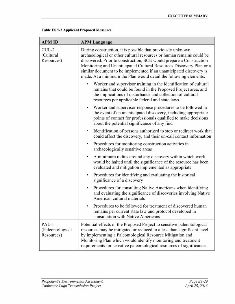
CUL-2 (Cultural Resources)
During construction, it is possible that previously unknown archaeological or other cultural resources or human remains could be discovered. Prior to construction, SCE would prepare a Construction Monitoring and Unanticipated Cultural Resources Discovery Plan or a similar document to be implemented if an unanticipated discovery is made. At a minimum the Plan would detail the following elements:
▪ Worker and supervisor training in the identification of cultural remains that could be found in the Proposed Project area, and the implications of disturbance and collection of cultural resources per applicable federal and state laws
▪ Worker and supervisor response procedures to be followed in the event of an unanticipated discovery, including appropriate points of contact for professionals qualified to make decisions about the potential significance of any find
▪ Identification of persons authorized to stop or redirect work that could affect the discovery, and their on-call contact information
▪ Procedures for monitoring construction activities in archaeologically sensitive areas
▪ A minimum radius around any discovery within which work would be halted until the significance of the resource has been evaluated and mitigation implemented as appropriate
▪ Procedures for identifying and evaluating the historical significance of a discovery
▪ Procedures for consulting Native Americans when identifying and evaluating the significance of discoveries involving Native American cultural materials
▪ Procedures to be followed for treatment of discovered human remains per current state law and protocol developed in consultation with Native Americans
PAL-1 (Paleontological Resources)
Potential effects of the Proposed Project to sensitive paleontological resources may be mitigated or reduced to a less than significant level by implementing a Paleontological Resource Mitigation and Monitoring Plan which would identify monitoring and treatment requirements for sensitive paleontological resources of significance.
1.0 PURPOSE AND NEED
Proponent’s Environmental Assessment Page 1-1 Coolwater-Lugo Transmission Project April 25, 2014
1.0 PURPOSE AND NEED
As part of the Renewable Energy Transmission Initiative (“RETI”)1, the Barstow, Inyokern, Kramer, Lucerne Valley, and Owens Valley areas, significant portions of which are under Bureau of Land Management (“BLM”) jurisdiction, have been identified to be rich solar and wind resource areas in the State of California. In addition, the Desert Renewable Energy Conservation Plan (“DRECP”)2 has also identified large amounts of renewable generation potential in the Mojave Desert area3. Existing generation in these areas, together with most of the identified future generation potential in the RETI competitive renewable energy zones and a significant portion of the generation potential in the DRECP development focus areas, would ultimately flow into Kramer Substation in Kramer Junction, CA and would then need to be exported south to Lugo Substation located in Hesperia, CA to serve customer demand in the Los Angeles basin.
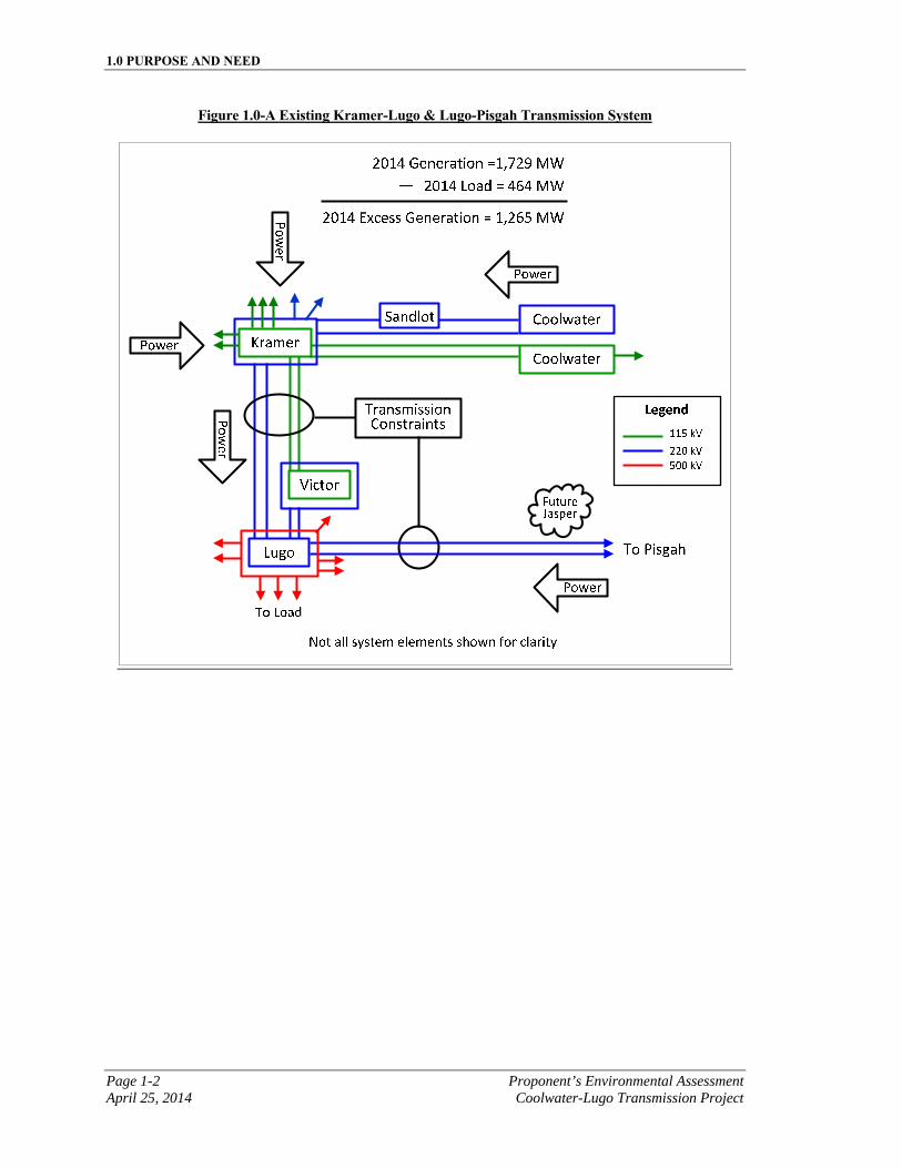
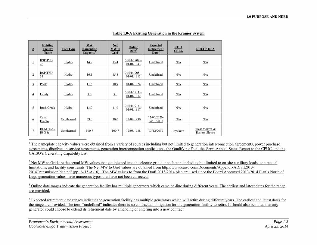
One of the major existing bottlenecks that would preclude the transfer of energy produced from renewable resources accumulating at Kramer Substation to Lugo Substation, is referred to as the Kramer-Lugo transmission corridor. This corridor consists of two 220 kilovolt (“kV”) and two 115 kV transmission lines with limited transfer capability due to existing facility limitations. Specifically, the Kramer-Lugo No.1 and No.2 220 kV transmission lines are currently at thermal capacity under peak system conditions, cannot be upgraded, and have become a transmission bottleneck. A second existing bottleneck that would also preclude the transfer of energy from future renewable resources developing in the Lucerne Valley area, near SCE’s future Jasper Substation, is referred to as the Lugo-Pisgah transmission corridor. Figure 1.0-A depicts a block diagram of the major transmission facilities associated with these two corridors and Table 1.0-A identifies the existing generation in the Kramer System.
1 http://www.energy.ca.gov/reti/
2 http://www.drecp.org/
3 http://www.drecp.org/meetings/2012-04-25-26_meeting/background/Transmission_Planning/Transmission_Technical_Group_report_final_4_16_12.pdf
1.0 PURPOSE AND NEED
Page 1-2 Proponent’s Environmental Assessment April 25, 2014 Coolwater-Lugo Transmission Project
Figure 1.0-A Existing Kramer-Lugo & Lugo-Pisgah Transmission System

1.0 PURPOSE AND NEED
Proponent’s Environmental Assessment Page 1-3 Coolwater-Lugo Transmission Project April 25, 2014
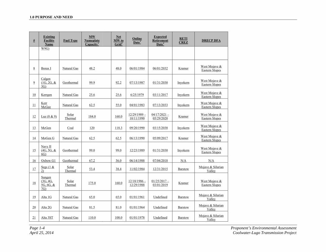
Table 1.0-A Existing Generation in the Kramer System
# Existing Facility Name
Fuel Type MW
Nameplate Capacity1
Net MW to Grid2
Online Date3
Expected Retirement
Date4
RETI CREZ DRECP DFA
1 BSPHYD 26
Hydro 14.9
13.4 01/01/1908 – 01/01/1943
Undefined N/A N/A
2 BSPHYD 34
Hydro 16.1
15.8 01/01/1905 – 01/01/1913
Undefined N/A N/A
3 Poole Hydro 11.3 10.9 01/01/1924 Undefined N/A N/A
4 Lundy Hydro 3.0
3.0 01/01/1911 – 01/01/1912
Undefined N/A N/A
5 Rush Creek Hydro 13.0
11.9 01/01/1916 – 01/01/1917
Undefined N/A N/A
6 Casa Diablo
Geothermal 39.0
30.0 12/07/1990 12/06/2020-04/01/2033
N/A N/A
7 BLM (E7G, E8G &
Geothermal 100.7
100.7 12/05/1988 03/12/2019 Inyokern West Mojave & Eastern Slopes
1 The nameplate capacity values were obtained from a variety of sources including but not limited to generation interconnection agreements, power purchase agreements, distribution service agreements, generation interconnection applications, the Qualifying Facilities Semi-Annual Status Report to the CPUC, and the CAISO’s Generating Capability List.
2 Net MW to Grid are the actual MW values that get injected into the electric grid due to factors including but limited to on-site auxiliary loads, contractual limitations, and facility constraints. The Net MW to Grid values are obtained from http://www.caiso.com/Documents/AppendixADraft2013-2014TransmissionPlan.pdf (pp. A-15-A-16). The MW values to from the Draft 2013-2014 plan are used since the Board Approved 2013-2014 Plan’s North of Lugo generation values have numerous typos that have not been corrected.
3 Online date ranges indicate the generation facility has multiple generators which came on-line during different years. The earliest and latest dates for the range are provided.
4 Expected retirement date ranges indicate the generation facility has multiple generators which will retire during different years. The earliest and latest dates for the range are provided. The term “undefined” indicates there is no contractual obligation for the generation facility to retire. It should also be noted that any generator could choose to extend its retirement date by amending or entering into a new contract.
1.0 PURPOSE AND NEED
Page 1-4 Proponent’s Environmental Assessment April 25, 2014 Coolwater-Lugo Transmission Project
# Existing Facility Name
Fuel Type MW
Nameplate Capacity1
Net MW to Grid2
Online Date3
Expected Retirement
Date4
RETI CREZ DRECP DFA
W9G)
8 Borax I Natural Gas 48.2
48.0 06/01/1984 06/01/2032 Kramer West Mojave & Eastern Slopes
9 Calgen (1G, 2G, & 3G)
Geothermal 99.9
92.2 07/13/1987 01/31/2030 Inyokern West Mojave & Eastern Slopes
10 Kerrgen Natural Gas 25.6
25.6 6/25/1979 03/11/2017 Inyokern West Mojave & Eastern Slopes
11 Kerr McGee
Natural Gas 62.5
55.0 04/01/1983 07/13/2033 Inyokern West Mojave & Eastern Slopes
12 Luz (8 & 9) Solar
Thermal 184.0
160.0
12/29/1989 – 10/11/1990
04/17/2021 – 05/29/2020
Kramer West Mojave & Eastern Slopes
13 McGen Coal 120
118.3 09/20/1990 03/15/2038 Inyokern West Mojave & Eastern Slopes
14 MoGen G Natural Gas 62.5
62.5 06/13/1990 05/09/2017 Kramer West Mojave & Eastern Slopes
15 Navy II (4G, 5G, & 6G)
Geothermal 99.0
99.0 12/23/1989 01/31/2030 Inyokern West Mojave & Eastern Slopes
16 Oxbow G1 Geothermal 67.2 56.0 06/14/1988 07/04/2018 N/A N/A
17 Segs (1 & 2)
Solar Thermal
53.4
38.4 11/02/1984 12/31/2015 Barstow Mojave & Silurian
Valley
18
Sungen (3G, 4G, 5G, 6G, & 7G)
Solar Thermal
175.0
160.0 12/18/1986 – 12/29/1988
01/25/2017 – 03/01/2019
Kramer West Mojave & Eastern Slopes
19 Alta 1G Natural Gas 65.0
65.0 01/01/1961 Undefined Barstow Mojave & Silurian
Valley
20 Alta 2G Natural Gas 81.5
81.0 01/01/1964 Undefined Barstow Mojave & Silurian
Valley
21 Alta 3ST Natural Gas 110.0
108.0 01/01/1978 Undefined Barstow Mojave & Silurian
Valley
1.0 PURPOSE AND NEED
Proponent’s Environmental Assessment Page 1-5 Coolwater-Lugo Transmission Project April 25, 2014
# Existing Facility Name
Fuel Type MW
Nameplate Capacity1
Net MW to Grid2
Online Date3
Expected Retirement
Date4
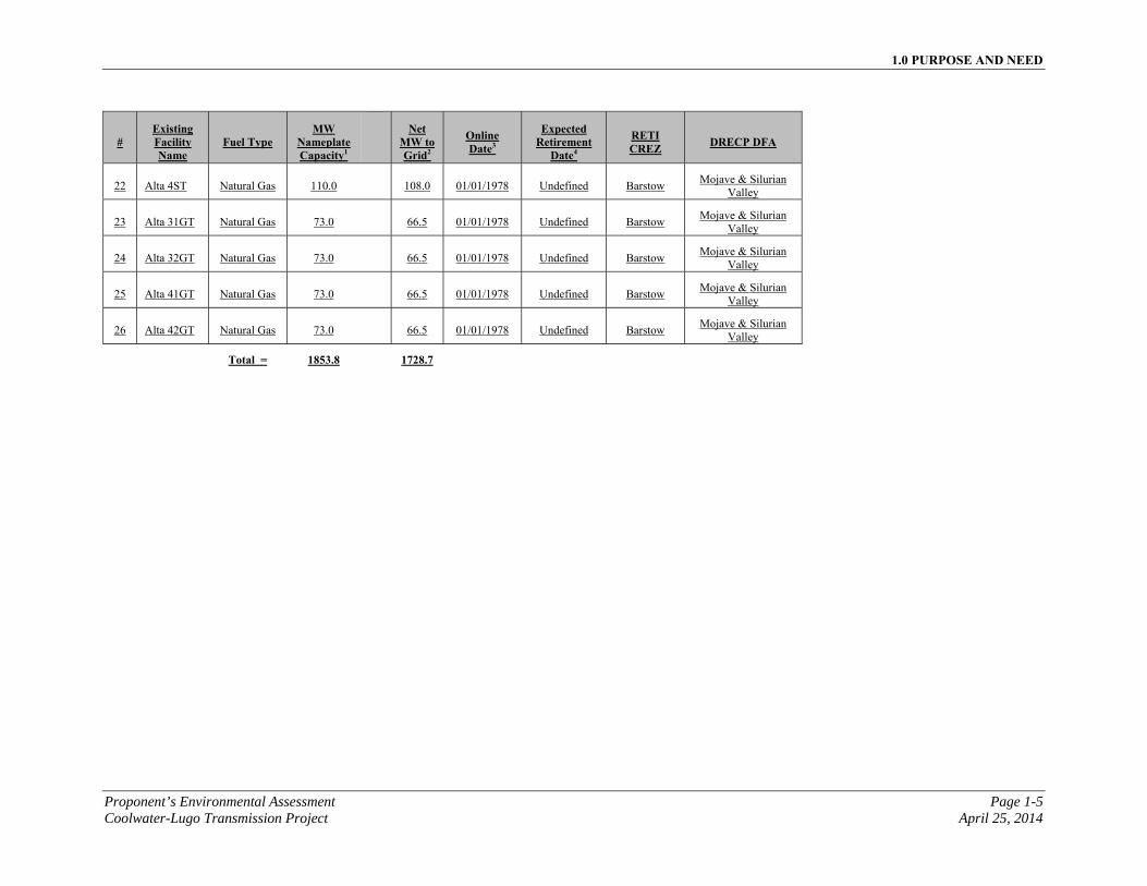
RETI CREZ DRECP DFA
22 Alta 4ST Natural Gas 110.0
108.0 01/01/1978 Undefined Barstow Mojave & Silurian
Valley
23 Alta 31GT Natural Gas 73.0
66.5 01/01/1978 Undefined Barstow Mojave & Silurian
Valley
24 Alta 32GT Natural Gas 73.0
66.5 01/01/1978 Undefined Barstow Mojave & Silurian
Valley
25 Alta 41GT Natural Gas 73.0
66.5 01/01/1978 Undefined Barstow Mojave & Silurian
Valley
26 Alta 42GT Natural Gas 73.0
66.5 01/01/1978 Undefined Barstow Mojave & Silurian
Valley
Total = 1853.8 1728.7

1.0 PURPOSE AND NEED
Page 1-6 Proponent’s Environmental Assessment April 25, 2014 Coolwater-Lugo Transmission Project
This page is intentionally blank
1.0 PURPOSE AND NEED
Proponent’s Environmental Assessment Page 1-7 Coolwater-Lugo Transmission Project April 25, 2014
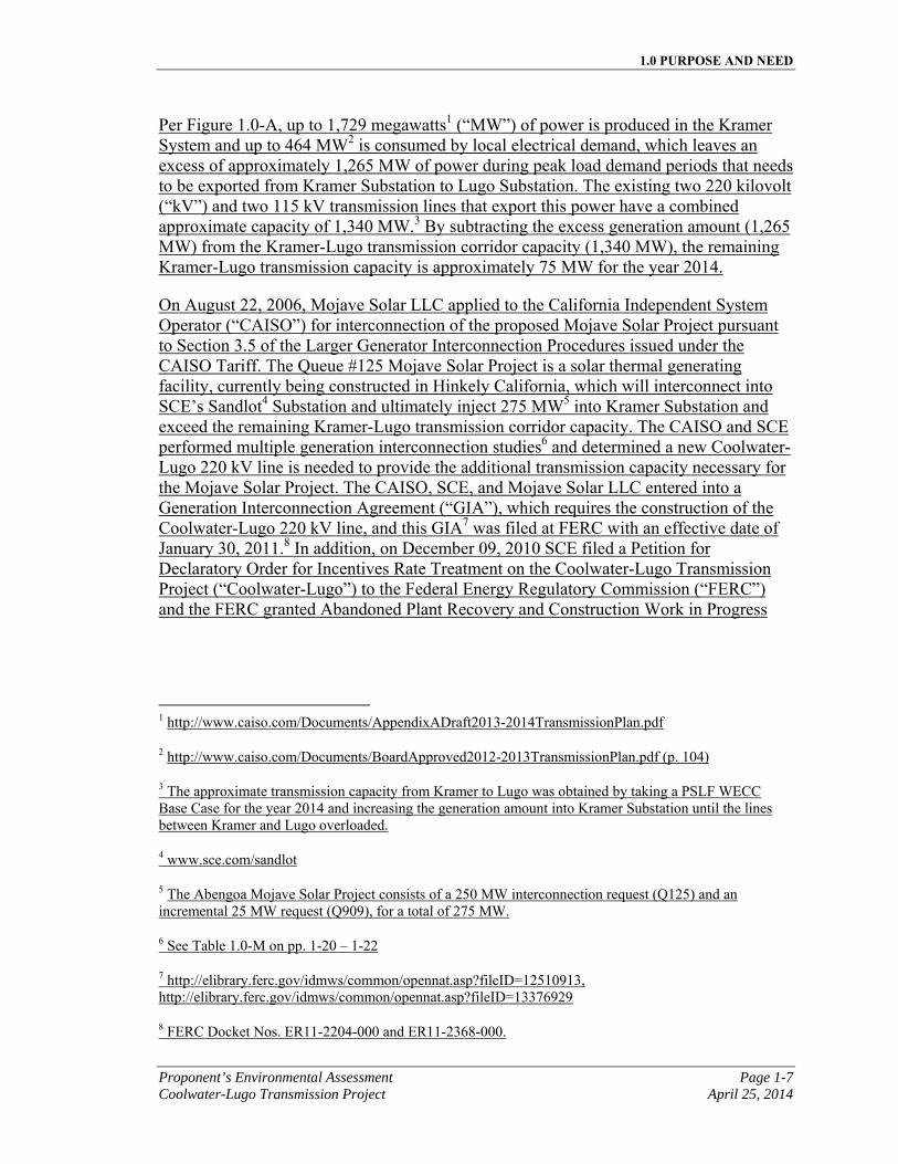
Per Figure 1.0-A, up to 1,729 megawatts1 (“MW”) of power is produced in the Kramer System and up to 464 MW2 is consumed by local electrical demand, which leaves an excess of approximately 1,265 MW of power during peak load demand periods that needs to be exported from Kramer Substation to Lugo Substation. The existing two 220 kilovolt (“kV”) and two 115 kV transmission lines that export this power have a combined approximate capacity of 1,340 MW.3 By subtracting the excess generation amount (1,265 MW) from the Kramer-Lugo transmission corridor capacity (1,340 MW), the remaining Kramer-Lugo transmission capacity is approximately 75 MW for the year 2014.
On August 22, 2006, Mojave Solar LLC applied to the California Independent System Operator (“CAISO”) for interconnection of the proposed Mojave Solar Project pursuant to Section 3.5 of the Larger Generator Interconnection Procedures issued under the CAISO Tariff. The Queue #125 Mojave Solar Project is a solar thermal generating facility, currently being constructed in Hinkely California, which will interconnect into SCE’s Sandlot4 Substation and ultimately inject 275 MW5 into Kramer Substation and exceed the remaining Kramer-Lugo transmission corridor capacity. The CAISO and SCE performed multiple generation interconnection studies6 and determined a new Coolwater-Lugo 220 kV line is needed to provide the additional transmission capacity necessary for the Mojave Solar Project. The CAISO, SCE, and Mojave Solar LLC entered into a Generation Interconnection Agreement (“GIA”), which requires the construction of the Coolwater-Lugo 220 kV line, and this GIA7 was filed at FERC with an effective date of January 30, 2011.8 In addition, on December 09, 2010 SCE filed a Petition for Declaratory Order for Incentives Rate Treatment on the Coolwater-Lugo Transmission Project (“Coolwater-Lugo”) to the Federal Energy Regulatory Commission (“FERC”) and the FERC granted Abandoned Plant Recovery and Construction Work in Progress
1 http://www.caiso.com/Documents/AppendixADraft2013-2014TransmissionPlan.pdf
2 http://www.caiso.com/Documents/BoardApproved2012-2013TransmissionPlan.pdf (p. 104)
3 The approximate transmission capacity from Kramer to Lugo was obtained by taking a PSLF WECC Base Case for the year 2014 and increasing the generation amount into Kramer Substation until the lines between Kramer and Lugo overloaded.
4 www.sce.com/sandlot
5 The Abengoa Mojave Solar Project consists of a 250 MW interconnection request (Q125) and an incremental 25 MW request (Q909), for a total of 275 MW.
6 See Table 1.0-M on pp. 1-20 – 1-22
7 http://elibrary.ferc.gov/idmws/common/opennat.asp?fileID=12510913, http://elibrary.ferc.gov/idmws/common/opennat.asp?fileID=13376929
8 FERC Docket Nos. ER11-2204-000 and ER11-2368-000.
1.0 PURPOSE AND NEED
Page 1-8 Proponent’s Environmental Assessment April 25, 2014 Coolwater-Lugo Transmission Project
(“CWIP”) incentives on March 11, 2011 to most of the major elements of Coolwater-Lugo.1
As of April 17, 2014, there are currently 11 generation projects in the CAISO and SCE generation queues requesting interconnection into the Kramer System and two projects requesting interconnection into SCE’s future Jasper Substation as shown in Tables 1.0-B to 1.0-D.
1 http://elibrary.ferc.gov/idmws/common/opennat.asp?fileID=12585841
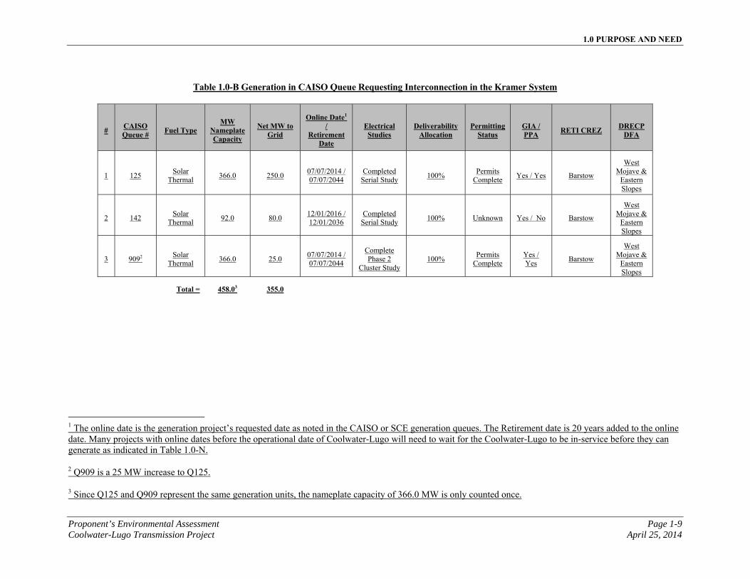
1.0 PURPOSE AND NEED
Proponent’s Environmental Assessment Page 1-9 Coolwater-Lugo Transmission Project April 25, 2014
Table 1.0-B Generation in CAISO Queue Requesting Interconnection in the Kramer System
# CAISO Queue # Fuel Type
MW Nameplate Capacity
Net MW to Grid
Online Date1 /
Retirement Date
Electrical Studies
Deliverability Allocation
Permitting Status
GIA / PPA RETI CREZ DRECP
DFA
1 125 Solar
Thermal
366.0
250.0 07/07/2014 / 07/07/2044
Completed Serial Study
100% Permits
Complete Yes / Yes Barstow
West Mojave &
Eastern Slopes
2 142 Solar
Thermal 92.0 80.0
12/01/2016 / 12/01/2036
Completed Serial Study
100% Unknown Yes / No Barstow
West Mojave &
Eastern Slopes
3 9092 Solar
Thermal 366.0 25.0
07/07/2014 / 07/07/2044
Complete Phase 2
Cluster Study 100%
Permits Complete
Yes / Yes
Barstow
West Mojave &
Eastern Slopes
Total = 458.03 355.0
1 The online date is the generation project’s requested date as noted in the CAISO or SCE generation queues. The Retirement date is 20 years added to the online date. Many projects with online dates before the operational date of Coolwater-Lugo will need to wait for the Coolwater-Lugo to be in-service before they can generate as indicated in Table 1.0-N.
2 Q909 is a 25 MW increase to Q125.
3 Since Q125 and Q909 represent the same generation units, the nameplate capacity of 366.0 MW is only counted once.
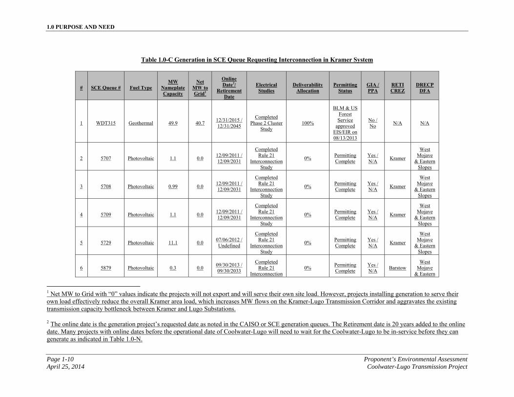
1.0 PURPOSE AND NEED
Page 1-10 Proponent’s Environmental Assessment April 25, 2014 Coolwater-Lugo Transmission Project
Table 1.0-C Generation in SCE Queue Requesting Interconnection in Kramer System
# SCE Queue # Fuel Type MW
Nameplate Capacity
Net MW to Grid1
Online Date2/
Retirement Date
Electrical Studies
Deliverability Allocation
Permitting Status
GIA / PPA
RETI CREZ
DRECP DFA
1 WDT315 Geothermal 49.9 40.7 12/31/2015 / 12/31/2045
Completed Phase 2 Cluster
Study 100%
BLM & US Forest Service
approved EIS/EIR on 08/13/2013
No / No
N/A N/A
2 5707 Photovoltaic 1.1 0.0 12/09/2011 / 12/09/2031
Completed Rule 21
Interconnection Study
0% Permitting Complete
Yes / N/A
Kramer
West Mojave
& Eastern Slopes
3 5708 Photovoltaic 0.99 0.0 12/09/2011 / 12/09/2031
Completed Rule 21
Interconnection Study
0% Permitting Complete
Yes / N/A
Kramer
West Mojave
& Eastern Slopes
4 5709 Photovoltaic 1.1 0.0 12/09/2011 / 12/09/2031
Completed Rule 21
Interconnection Study
0% Permitting Complete
Yes / N/A
Kramer
West Mojave
& Eastern Slopes
5 5729 Photovoltaic 11.1 0.0 07/06/2012 / Undefined
Completed Rule 21
Interconnection Study
0% Permitting Complete
Yes / N/A
Kramer
West Mojave
& Eastern Slopes
6 5879 Photovoltaic 0.3 0.0 09/30/2013 / 09/30/2033
Completed Rule 21
Interconnection 0%
Permitting Complete
Yes / N/A
Barstow West
Mojave & Eastern
1 Net MW to Grid with “0” values indicate the projects will not export and will serve their own site load. However, projects installing generation to serve their own load effectively reduce the overall Kramer area load, which increases MW flows on the Kramer-Lugo Transmission Corridor and aggravates the existing transmission capacity bottleneck between Kramer and Lugo Substations.
2 The online date is the generation project’s requested date as noted in the CAISO or SCE generation queues. The Retirement date is 20 years added to the online date. Many projects with online dates before the operational date of Coolwater-Lugo will need to wait for the Coolwater-Lugo to be in-service before they can generate as indicated in Table 1.0-N.
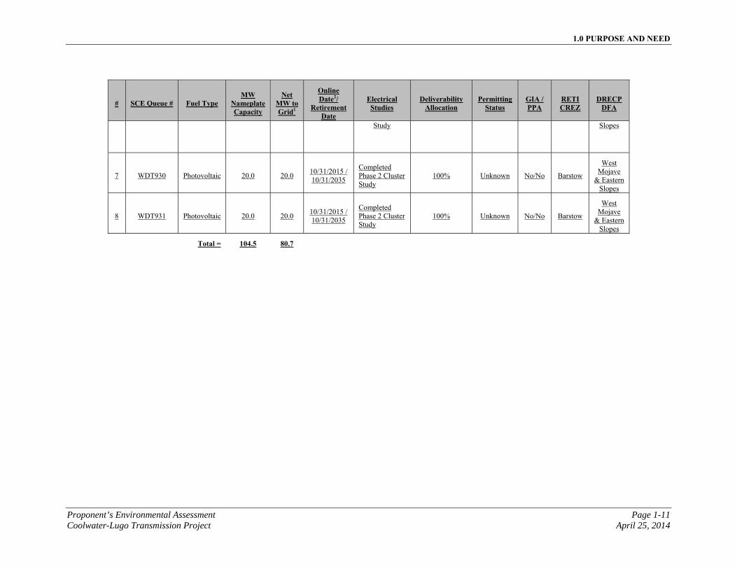
1.0 PURPOSE AND NEED
Proponent’s Environmental Assessment Page 1-11 Coolwater-Lugo Transmission Project April 25, 2014
# SCE Queue # Fuel Type MW
Nameplate Capacity
Net MW to Grid1
Online Date2/
Retirement Date
Electrical Studies
Deliverability Allocation
Permitting Status
GIA / PPA
RETI CREZ
DRECP DFA
Study Slopes
7 WDT930 Photovoltaic 20.0 20.0 10/31/2015 / 10/31/2035
Completed Phase 2 Cluster Study
100% Unknown No/No Barstow
West Mojave
& Eastern Slopes
8 WDT931 Photovoltaic 20.0 20.0 10/31/2015 / 10/31/2035
Completed Phase 2 Cluster Study
100% Unknown No/No Barstow
West Mojave
& Eastern Slopes
Total = 104.5 80.7
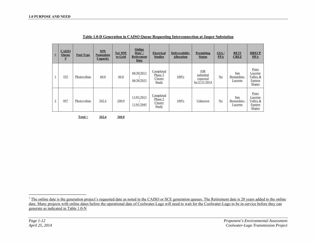
1.0 PURPOSE AND NEED
Page 1-12 Proponent’s Environmental Assessment April 25, 2014 Coolwater-Lugo Transmission Project
Table 1.0-D Generation in CAISO Queue Requesting Interconnection at Jasper Substation
# CAISO Queue
# Fuel Type
MW Nameplate Capacity
Net MW to Grid
Online Date1 /
Retirement Date
Electrical Studies
Deliverability Allocation
Permitting Status
GIA / PPA
RETI CREZ
DRECP DFA
1 552 Photovoltaic 60.0 60.0 04/30/2013
/ 04/30/2033
Completed Phase 2 Cluster Study
100%
EIR submittal expected
by12/31/2014
No San
Bernardino-Lucerne
Pinto Lucerne Valley & Eastern Slopes
2 897 Photovoltaic 202.6 200.0 11/01/2015
/ 11/01/2045
Completed Phase 2 Cluster Study
100% Unknown No San
Bernardino-Lucerne
Pinto Lucerne Valley & Eastern Slopes
Total = 262.6 260.0
1 The online date is the generation project’s requested date as noted in the CAISO or SCE generation queues. The Retirement date is 20 years added to the online date. Many projects with online dates before the operational date of Coolwater-Lugo will need to wait for the Coolwater-Lugo to be in-service before they can generate as indicated in Table 1.0-N
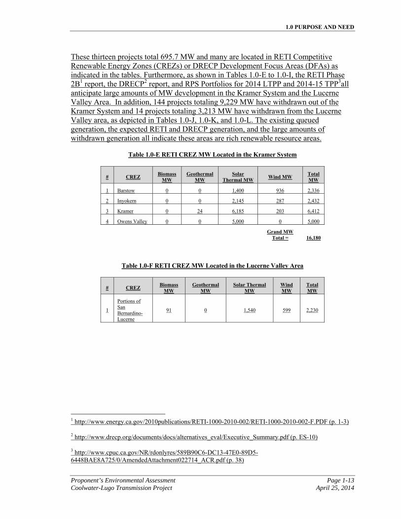
1.0 PURPOSE AND NEED
Proponent’s Environmental Assessment Page 1-13 Coolwater-Lugo Transmission Project April 25, 2014
These thirteen projects total 695.7 MW and many are located in RETI Competitive Renewable Energy Zones (CREZs) or DRECP Development Focus Areas (DFAs) as indicated in the tables. Furthermore, as shown in Tables 1.0-E to 1.0-I, the RETI Phase 2B1 report, the DRECP2 report, and RPS Portfolios for 2014 LTPP and 2014-15 TPP3all anticipate large amounts of MW development in the Kramer System and the Lucerne Valley Area. In addition, 144 projects totaling 9,229 MW have withdrawn out of the Kramer System and 14 projects totaling 3,213 MW have withdrawn from the Lucerne Valley area, as depicted in Tables 1.0-J, 1.0-K, and 1.0-L. The existing queued generation, the expected RETI and DRECP generation, and the large amounts of withdrawn generation all indicate these areas are rich renewable resource areas.
Table 1.0-E RETI CREZ MW Located in the Kramer System
# CREZ Biomass MW
Geothermal MW
Solar Thermal MW Wind MW Total
MW
1 Barstow 0 0 1,400 936 2,336
2 Inyokern 0 0 2,145 287 2,432
3 Kramer 0 24 6,185 203 6,412
4 Owens Valley 0 0 5,000 0 5,000
Grand MW
Total = 16,180
Table 1.0-F RETI CREZ MW Located in the Lucerne Valley Area
# CREZ Biomass MW
Geothermal MW
Solar Thermal MW
Wind MW
Total MW
1
Portions of San Bernardino-Lucerne
91 0 1,540 599 2,230
1 http://www.energy.ca.gov/2010publications/RETI-1000-2010-002/RETI-1000-2010-002-F.PDF (p. 1-3)
2 http://www.drecp.org/documents/docs/alternatives_eval/Executive_Summary.pdf (p. ES-10)
3 http://www.cpuc.ca.gov/NR/rdonlyres/589B90C6-DC13-47E0-89D5-6448BAE8A725/0/AmendedAttachment022714_ACR.pdf (p. 38)
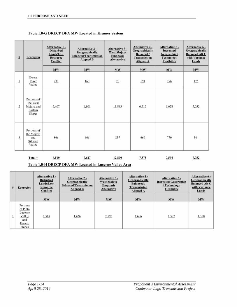
1.0 PURPOSE AND NEED
Page 1-14 Proponent’s Environmental Assessment April 25, 2014 Coolwater-Lugo Transmission Project
Table 1.0-G DRECP DFA MW Located in Kramer System
# Ecoregion
Alternative 1 - Disturbed
Lands/Low Resource Conflict
Alternative 2 - Geographically
Balanced/Transmission Aligned B
Alternative 3 - West Mojave
Emphasis Alternative
Alternative 4 - Geographically
Balanced / Transmission
Aligned A
Alternative 5 - Increased
Geographic / Technology Flexibility
Alternative 6 - Geographically Balanced Alt C with Variance
Lands
MW MW MW MW MW MW
1 Owens River Valley
237 160 70 191 196 175
2
Portions of the West
Mojave and Eastern Slopes
5,407 6,801 11,893 6,515 6,628 7,033
3
Portions of the Mojave
and Silurian Valley
866 666 837 669 770 544
Total = 6,510 7,627 12,800 7,375 7,594 7,752
Table 1.0-H DRECP DFA MW Located in Lucerne Valley Area
# Ecoregion
Alternative 1 - Disturbed
Lands/Low Resource Conflict
Alternative 2 - Geographically
Balanced/Transmission Aligned B
Alternative 3 - West Mojave
Emphasis Alternative
Alternative 4 - Geographically
Balanced / Transmission
Aligned A
Alternative 5 - Increased Geographic
/ Technology Flexibility
Alternative 6 - Geographically Balanced Alt C with Variance
Lands
MW MW MW MW MW MW
1
Portions of Pinto Lucerne Valley
and Eastern Slopes
1,518 1,426 2,595 1,686 1,597 1,300
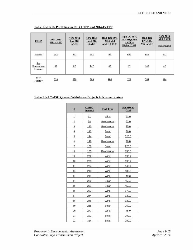
1.0 PURPOSE AND NEED
Proponent’s Environmental Assessment Page 1-15 Coolwater-Lugo Transmission Project April 25, 2014
Table 1.0-I RPS Portfolios for 2014 LTPP and 2014-15 TPP
CREZ 33% 2024 Mid AAEE
33% 2024 LowMid AAEE
33% High Load Mid
AAEE
High DG 33% 2024 Mid
AAEE + DSM
High DG 40% 2024 HighMid
AAEE + Higher DSM
High DG 40% 2024
Mid AAEE
33% 2024 Mid AAEE
(sensitivity)
Kramer 642 642 642 62 642 642 642
San Bernardino-
Lucerne 87 87 147 42 87 147 42
MW Totals = 729 729 789 104 729 789 684
Table 1.0-J CAISO Queued Withdrawn Projects in Kramer System
# CAISO Queue # Fuel Type Net MW to
Grid
1 11 Wind 63.0
2 58 Geothermal 62.0
3 140 Geothermal 75.0
4 143 Solar 80.0
5 144 Solar 320.0
6 148 Geothermal 90.0
7 160 Solar 220.0
8 185 Geothermal 150.0
9 202 Wind 198.7
10 203 Wind 198.7
11 204 Wind 149.4
12 213 Wind 180.0
13 214 Wind 49.3
14 220 Solar 450.0
15 221 Solar 450.0
16 223 Wind 170.0
17 244 Wind 120.0
18 246 Wind 120.0
19 255 Solar 250.0
20 277 Wind 75.0
21 292 Solar 250.0
22 324 Solar 250.0
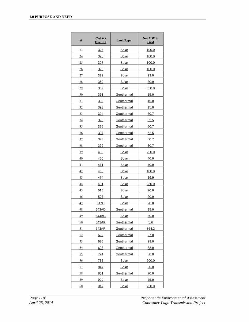
1.0 PURPOSE AND NEED
Page 1-16 Proponent’s Environmental Assessment April 25, 2014 Coolwater-Lugo Transmission Project
# CAISO Queue # Fuel Type Net MW to
Grid
23 325 Solar 100.0
24 326 Solar 100.0
25 327 Solar 100.0
26 328 Solar 100.0
27 333 Solar 33.0
28 350 Solar 80.0
29 359 Solar 350.0
30 391 Geothermal 15.0
31 392 Geothermal 15.0
32 393 Geothermal 15.0
33 394 Geothermal 60.7
34 395 Geothermal 52.5
35 396 Geothermal 60.7
36 397 Geothermal 52.5
37 398 Geothermal 60.7
38 399 Geothermal 60.7
39 430 Solar 250.0
40 460 Solar 40.0
41 461 Solar 40.0
42 466 Solar 100.0
43 474 Solar 19.9
44 491 Solar 230.0
45 515 Solar 20.0
46 527 Solar 20.0
47 617C Solar 20.0
48 643AD Geothermal 95.0
49 643AG Solar 50.0
50 643AK Geothermal 5.6
51 643AR Geothermal 364.2
52 692 Geothermal 27.0
53 695 Geothermal 38.0
54 698 Geothermal 38.0
55 774 Geothermal 38.0
56 783 Solar 200.0
57 847 Solar 20.0
58 851 Geothermal 70.0
59 920 Solar 75.0
60 942 Solar 250.0
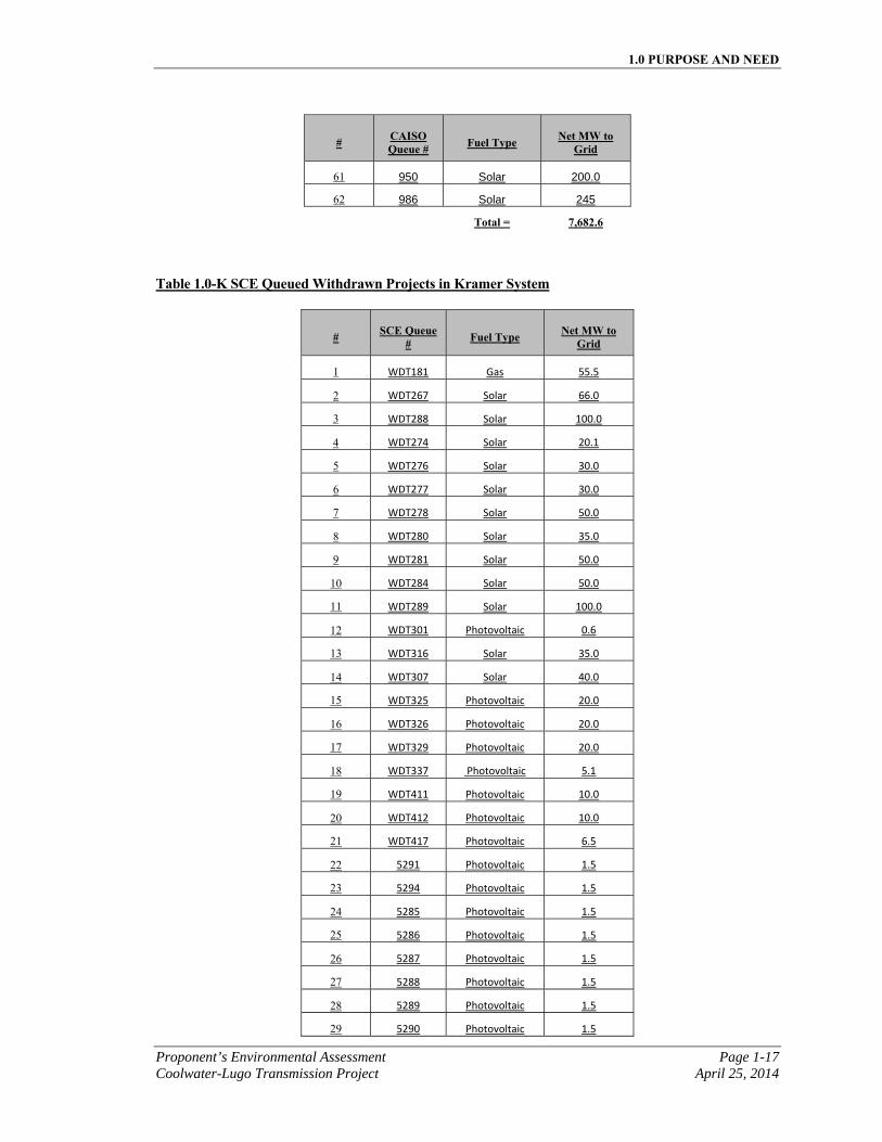
1.0 PURPOSE AND NEED
Proponent’s Environmental Assessment Page 1-17 Coolwater-Lugo Transmission Project April 25, 2014
# CAISO Queue # Fuel Type Net MW to
Grid
61 950 Solar 200.0
62 986 Solar 245
Total = 7,682.6
Table 1.0-K SCE Queued Withdrawn Projects in Kramer System
# SCE Queue # Fuel Type Net MW to
Grid
1 WDT181 Gas 55.5
2 WDT267 Solar 66.0
3 WDT288 Solar 100.0
4 WDT274 Solar 20.1
5 WDT276 Solar 30.0
6 WDT277 Solar 30.0
7 WDT278 Solar 50.0
8 WDT280 Solar 35.0
9 WDT281 Solar 50.0
10 WDT284 Solar 50.0
11 WDT289 Solar 100.0
12 WDT301 Photovoltaic 0.6
13 WDT316 Solar 35.0
14 WDT307 Solar 40.0
15 WDT325 Photovoltaic 20.0
16 WDT326 Photovoltaic 20.0
17 WDT329 Photovoltaic 20.0
18 WDT337 Photovoltaic 5.1
19 WDT411 Photovoltaic 10.0
20 WDT412 Photovoltaic 10.0
21 WDT417 Photovoltaic 6.5
22 5291 Photovoltaic 1.5
23 5294 Photovoltaic 1.5
24 5285 Photovoltaic 1.5
25 5286 Photovoltaic 1.5
26 5287 Photovoltaic 1.5
27 5288 Photovoltaic 1.5
28 5289 Photovoltaic 1.5
29 5290 Photovoltaic 1.5
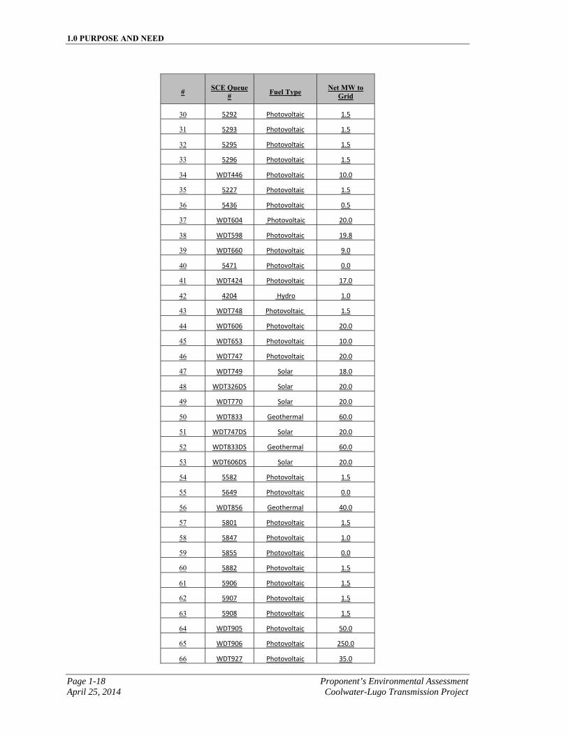
1.0 PURPOSE AND NEED
Page 1-18 Proponent’s Environmental Assessment April 25, 2014 Coolwater-Lugo Transmission Project
# SCE Queue # Fuel Type Net MW to
Grid
30 5292 Photovoltaic 1.5
31 5293 Photovoltaic 1.5
32 5295 Photovoltaic 1.5
33 5296 Photovoltaic 1.5
34 WDT446 Photovoltaic 10.0
35 5227 Photovoltaic 1.5
36 5436 Photovoltaic 0.5
37 WDT604 Photovoltaic 20.0
38 WDT598 Photovoltaic 19.8
39 WDT660 Photovoltaic 9.0
40 5471 Photovoltaic 0.0
41 WDT424 Photovoltaic 17.0
42 4204 Hydro 1.0
43 WDT748 Photovoltaic 1.5
44 WDT606 Photovoltaic 20.0
45 WDT653 Photovoltaic 10.0
46 WDT747 Photovoltaic 20.0
47 WDT749 Solar 18.0
48 WDT326DS Solar 20.0
49 WDT770 Solar 20.0
50 WDT833 Geothermal 60.0
51 WDT747DS Solar 20.0
52 WDT833DS Geothermal 60.0
53 WDT606DS Solar 20.0
54 5582 Photovoltaic 1.5
55 5649 Photovoltaic 0.0
56 WDT856 Geothermal 40.0
57 5801 Photovoltaic 1.5
58 5847 Photovoltaic 1.0
59 5855 Photovoltaic 0.0
60 5882 Photovoltaic 1.5
61 5906 Photovoltaic 1.5
62 5907 Photovoltaic 1.5
63 5908 Photovoltaic 1.5
64 WDT905 Photovoltaic 50.0
65 WDT906 Photovoltaic 250.0
66 WDT927 Photovoltaic 35.0
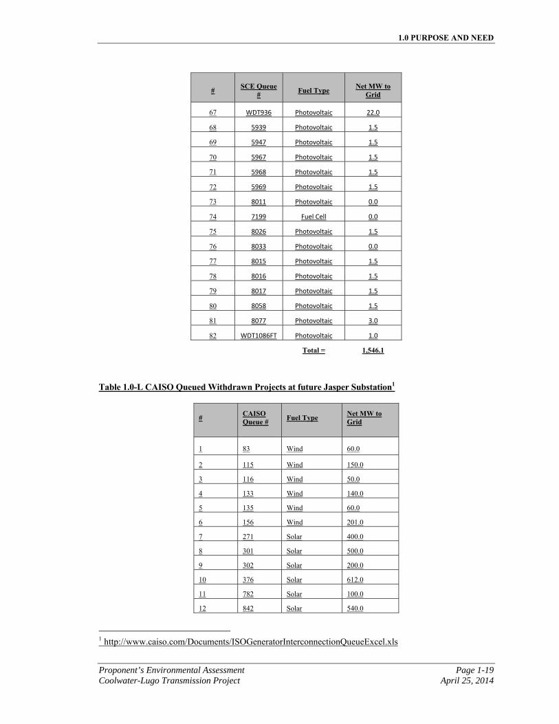
1.0 PURPOSE AND NEED
Proponent’s Environmental Assessment Page 1-19 Coolwater-Lugo Transmission Project April 25, 2014
# SCE Queue # Fuel Type Net MW to
Grid
67 WDT936 Photovoltaic 22.0
68 5939 Photovoltaic 1.5
69 5947 Photovoltaic 1.5
70 5967 Photovoltaic 1.5
71 5968 Photovoltaic 1.5
72 5969 Photovoltaic 1.5
73 8011 Photovoltaic 0.0
74 7199 Fuel Cell 0.0
75 8026 Photovoltaic 1.5
76 8033 Photovoltaic 0.0
77 8015 Photovoltaic 1.5
78 8016 Photovoltaic 1.5
79 8017 Photovoltaic 1.5
80 8058 Photovoltaic 1.5
81 8077 Photovoltaic 3.0
82 WDT1086FT Photovoltaic 1.0
Total = 1,546.1
Table 1.0-L CAISO Queued Withdrawn Projects at future Jasper Substation1
# CAISO Queue # Fuel Type Net MW to
Grid
1 83 Wind 60.0
2 115 Wind 150.0
3 116 Wind 50.0
4 133 Wind 140.0
5 135 Wind 60.0
6 156 Wind 201.0
7 271 Solar 400.0
8 301 Solar 500.0
9 302 Solar 200.0
10 376 Solar 612.0
11 782 Solar 100.0
12 842 Solar 540.0
1 http://www.caiso.com/Documents/ISOGeneratorInterconnectionQueueExcel.xls
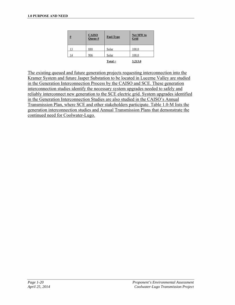
1.0 PURPOSE AND NEED
Page 1-20 Proponent’s Environmental Assessment April 25, 2014 Coolwater-Lugo Transmission Project
# CAISO Queue # Fuel Type Net MW to
Grid
13 888 Solar 100.0
14 906 Solar 100.0
Total = 3,213.0
The existing queued and future generation projects requesting interconnection into the Kramer System and future Jasper Substation to be located in Lucerne Valley are studied in the Generation Interconnection Process by the CAISO and SCE. These generation interconnection studies identify the necessary system upgrades needed to safely and reliably interconnect new generation to the SCE electric grid. System upgrades identified in the Generation Interconnection Studies are also studied in the CAISO’s Annual Transmission Plan, where SCE and other stakeholders participate. Table 1.0-M lists the generation interconnection studies and Annual Transmission Plans that demonstrate the continued need for Coolwater-Lugo.
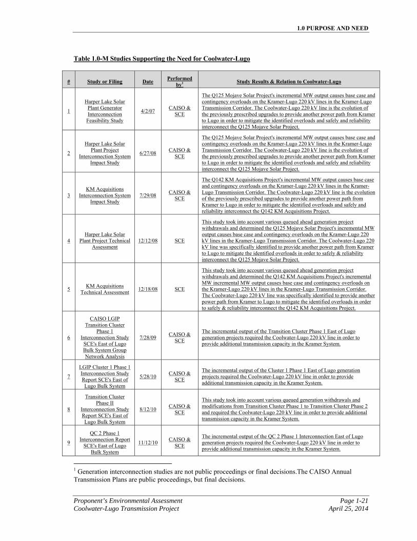
1.0 PURPOSE AND NEED
Proponent’s Environmental Assessment Page 1-21 Coolwater-Lugo Transmission Project April 25, 2014
Table 1.0-M Studies Supporting the Need for Coolwater-Lugo
# Study or Filing Date Performed by1 Study Results & Relation to Coolwater-Lugo
1
Harper Lake Solar Plant Generator Interconnection
Feasibility Study
4/2/07 CAISO &
SCE
The Q125 Mojave Solar Project's incremental MW output causes base case and contingency overloads on the Kramer-Lugo 220 kV lines in the Kramer-Lugo Transmission Corridor. The Coolwater-Lugo 220 kV line is the evolution of the previously prescribed upgrades to provide another power path from Kramer to Lugo in order to mitigate the identified overloads and safely and reliability interconnect the Q125 Mojave Solar Project.
2
Harper Lake Solar Plant Project
Interconnection System Impact Study
6/27/08 CAISO &
SCE
The Q125 Mojave Solar Project's incremental MW output causes base case and contingency overloads on the Kramer-Lugo 220 kV lines in the Kramer-Lugo Transmission Corridor. The Coolwater-Lugo 220 kV line is the evolution of the previously prescribed upgrades to provide another power path from Kramer to Lugo in order to mitigate the identified overloads and safely and reliability interconnect the Q125 Mojave Solar Project.
3 KM Acquisitions
Interconnection System Impact Study
7/29/08 CAISO &
SCE
The Q142 KM Acquisitions Project's incremental MW output causes base case and contingency overloads on the Kramer-Lugo 220 kV lines in the Kramer-Lugo Transmission Corridor. The Coolwater-Lugo 220 kV line is the evolution of the previously prescribed upgrades to provide another power path from Kramer to Lugo in order to mitigate the identified overloads and safely and reliability interconnect the Q142 KM Acquisitions Project.
4 Harper Lake Solar
Plant Project Technical Assessment
12/12/08 SCE
This study took into account various queued ahead generation project withdrawals and determined the Q125 Mojave Solar Project's incremental MW output causes base case and contingency overloads on the Kramer-Lugo 220 kV lines in the Kramer-Lugo Transmission Corridor. The Coolwater-Lugo 220 kV line was specifically identified to provide another power path from Kramer to Lugo to mitigate the identified overloads in order to safely & reliability interconnect the Q125 Mojave Solar Project.
5 KM Acquisitions
Technical Assessment 12/18/08 SCE
This study took into account various queued ahead generation project withdrawals and determined the Q142 KM Acquisitions Project's incremental MW incremental MW output causes base case and contingency overloads on the Kramer-Lugo 220 kV lines in the Kramer-Lugo Transmission Corridor. The Coolwater-Lugo 220 kV line was specifically identified to provide another power path from Kramer to Lugo to mitigate the identified overloads in order to safely & reliability interconnect the Q142 KM Acquisitions Project.
6
CAISO LGIP Transition Cluster
Phase 1 Interconnection Study
SCE's East of Lugo Bulk System Group Network Analysis
7/28/09 CAISO &
SCE
The incremental output of the Transition Cluster Phase 1 East of Lugo generation projects required the Coolwater-Lugo 220 kV line in order to provide additional transmission capacity in the Kramer System.
7
LGIP Cluster 1 Phase 1 Interconnection Study Report SCE's East of Lugo Bulk System
5/28/10 CAISO &
SCE
The incremental output of the Cluster 1 Phase 1 East of Lugo generation projects required the Coolwater-Lugo 220 kV line in order to provide additional transmission capacity in the Kramer System.
8
Transition Cluster Phase II
Interconnection Study Report SCE's East of Lugo Bulk System
8/12/10 CAISO &
SCE
This study took into account various queued generation withdrawals and modifications from Transition Cluster Phase 1 to Transition Cluster Phase 2 and required the Coolwater-Lugo 220 kV line in order to provide additional transmission capacity in the Kramer System.
9
QC 2 Phase 1 Interconnection Report
SCE's East of Lugo Bulk System
11/12/10 CAISO &
SCE
The incremental output of the QC 2 Phase 1 Interconnection East of Lugo generation projects required the Coolwater-Lugo 220 kV line in order to provide additional transmission capacity in the Kramer System.
1 Generation interconnection studies are not public proceedings or final decisions.The CAISO Annual Transmission Plans are public proceedings, but final decisions.
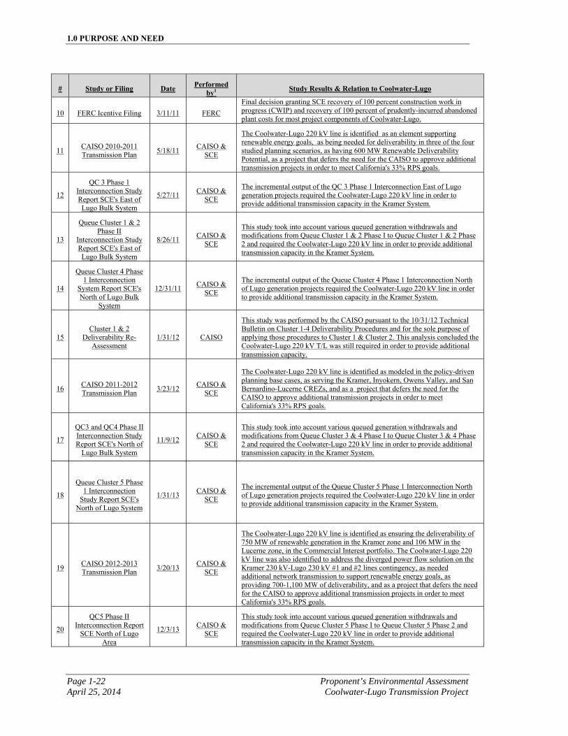
1.0 PURPOSE AND NEED
Page 1-22 Proponent’s Environmental Assessment April 25, 2014 Coolwater-Lugo Transmission Project
# Study or Filing Date Performed by1 Study Results & Relation to Coolwater-Lugo
10 FERC Icentive Filing 3/11/11 FERC
Final decision granting SCE recovery of 100 percent construction work in progress (CWIP) and recovery of 100 percent of prudently-incurred abandoned plant costs for most project components of Coolwater-Lugo.
11 CAISO 2010-2011 Transmission Plan
5/18/11 CAISO &
SCE
The Coolwater-Lugo 220 kV line is identified as an element supporting renewable energy goals, as being needed for deliverability in three of the four studied planning scenarios, as having 600 MW Renewable Deliverability Potential, as a project that defers the need for the CAISO to approve additional transmission projects in order to meet California's 33% RPS goals.
12
QC 3 Phase 1 Interconnection Study Report SCE's East of Lugo Bulk System
5/27/11 CAISO &
SCE
The incremental output of the QC 3 Phase 1 Interconnection East of Lugo generation projects required the Coolwater-Lugo 220 kV line in order to provide additional transmission capacity in the Kramer System.
13
Queue Cluster 1 & 2 Phase II
Interconnection Study Report SCE's East of Lugo Bulk System
8/26/11 CAISO &
SCE
This study took into account various queued generation withdrawals and modifications from Queue Cluster 1 & 2 Phase I to Queue Cluster 1 & 2 Phase 2 and required the Coolwater-Lugo 220 kV line in order to provide additional transmission capacity in the Kramer System.
14
Queue Cluster 4 Phase 1 Interconnection
System Report SCE's North of Lugo Bulk
System
12/31/11 CAISO &
SCE
The incremental output of the Queue Cluster 4 Phase 1 Interconnection North of Lugo generation projects required the Coolwater-Lugo 220 kV line in order to provide additional transmission capacity in the Kramer System.
15 Cluster 1 & 2
Deliverability Re-Assessment
1/31/12 CAISO
This study was performed by the CAISO pursuant to the 10/31/12 Technical Bulletin on Cluster 1-4 Deliverability Procedures and for the sole purpose of applying those procedures to Cluster 1 & Cluster 2. This analysis concluded the Coolwater-Lugo 220 kV T/L was still required in order to provide additional transmission capacity.
16 CAISO 2011-2012 Transmission Plan
3/23/12 CAISO &
SCE
The Coolwater-Lugo 220 kV line is identified as modeled in the policy-driven planning base cases, as serving the Kramer, Inyokern, Owens Valley, and San Bernardino-Lucerne CREZs, and as a project that defers the need for the CAISO to approve additional transmission projects in order to meet California's 33% RPS goals.
17
QC3 and QC4 Phase II Interconnection Study Report SCE's North of
Lugo Bulk System
11/9/12 CAISO &
SCE
This study took into account various queued generation withdrawals and modifications from Queue Cluster 3 & 4 Phase I to Queue Cluster 3 & 4 Phase 2 and required the Coolwater-Lugo 220 kV line in order to provide additional transmission capacity in the Kramer System.
18
Queue Cluster 5 Phase 1 Interconnection
Study Report SCE's North of Lugo System
1/31/13 CAISO &
SCE
The incremental output of the Queue Cluster 5 Phase 1 Interconnection North of Lugo generation projects required the Coolwater-Lugo 220 kV line in order to provide additional transmission capacity in the Kramer System.
19 CAISO 2012-2013 Transmission Plan
3/20/13 CAISO &
SCE
The Coolwater-Lugo 220 kV line is identified as ensuring the deliverability of 750 MW of renewable generation in the Kramer zone and 106 MW in the Lucerne zone, in the Commercial Interest portfolio. The Coolwater-Lugo 220 kV line was also identified to address the diverged power flow solution on the Kramer 230 kV-Lugo 230 kV #1 and #2 lines contingency, as needed additional network transmission to support renewable energy goals, as providing 700-1,100 MW of deliverability, and as a project that defers the need for the CAISO to approve additional transmission projects in order to meet California's 33% RPS goals.
20
QC5 Phase II Interconnection Report
SCE North of Lugo Area
12/3/13 CAISO &
SCE
This study took into account various queued generation withdrawals and modifications from Queue Cluster 5 Phase I to Queue Cluster 5 Phase 2 and required the Coolwater-Lugo 220 kV line in order to provide additional transmission capacity in the Kramer System.
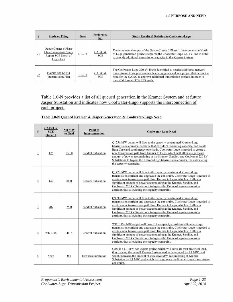
1.0 PURPOSE AND NEED
Proponent’s Environmental Assessment Page 1-23 Coolwater-Lugo Transmission Project April 25, 2014
# Study or Filing Date Performed by1 Study Results & Relation to Coolwater-Lugo
21
Queue Cluster 6 Phase I Interconnection Study Report SCE North of
Lugo Area
1/17/14 CAISO &
SCE
The incremental output of the Queue Cluster 5 Phase 1 Interconnection North of Lugo generation projects required the Coolwater-Lugo 220 kV line in order to provide additional transmission capacity in the Kramer System.
22 CAISO 2013-2014 Transmission Plan
3/12/14 CAISO &
SCE
The Coolwater-Lugo 220 kV line is identified as needed additional network transmission to support renewable energy goals and as a project that defers the need for the CAISO to approve additional transmission projects in order to meet California's 33% RPS goals.
Table 1.0-N provides a list of all queued generation in the Kramer System and at future Jasper Substation and indicates how Coolwater-Lugo supports the interconnection of each project.
Table 1.0-N Queued Kramer & Jasper Generation & Coolwater-Lugo Need
# CAISO or
SCE Queue #
Net MW to Grid
Point of Interconnection Coolwater-Lugo Need
1 125 250.0 Sandlot Substation
Q125's MW output will flow to the capacity constrained Kramer-Lugo transmission corridor, consume that corridor's remaining capacity, and create Base Case and contingency overloads. Coolwater-Lugo is needed to create a new transmission path from Kramer to Lugo, which will allow a significant amount of power accumulating at the Kramer, Sandlot, and Coolwater 220 kV Substations to bypass the Kramer-Lugo transmission corridor, thus alleviating the capacity constraint.
2 142 80.0 Kramer Substation
Q142's MW output will flow to the capacity constrained Kramer-Lugo transmission corridor and aggravate the constraint. Coolwater-Lugo is needed to create a new transmission path from Kramer to Lugo, which will allow a significant amount of power accumulating at the Kramer, Sandlot, and Coolwater 220 kV Substations to bypass the Kramer-Lugo transmission corridor, thus alleviating the capacity constraint.
3 909 25.0 Sandlot Substation
Q909's MW output will flow to the capacity constrained Kramer-Lugo transmission corridor and aggravate the constraint. Coolwater-Lugo is needed to create a new transmission path from Kramer to Lugo, which will allow a significant amount of power accumulating at the Kramer, Sandlot, and Coolwater 220 kV Substations to bypass the Kramer-Lugo transmission corridor, thus alleviating the capacity constraint.
4 WDT315 40.7 Control Substation
WDT315's MW output will flow to the capacity constrained Kramer-Lugo transmission corridor and aggravate the constraint. Coolwater-Lugo is needed to create a new transmission path from Kramer to Lugo, which will allow a significant amount of power accumulating at the Kramer, Sandlot, and Coolwater 220 kV Substations to bypass the Kramer-Lugo transmission corridor, thus alleviating the capacity constraint.
5 5707 0.0 Edwards Substation
5707 is a 1.1 MW non-export project which will serve its own electrical load, thus causing the overall Kramer System load to be reduced by 1.1 MW, and which increases the amount of excessive MW accumulating at Kramer Substation by 1.1 MW, and which will aggravate the Kramer-Lugo transmission constraint.
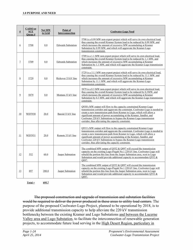
1.0 PURPOSE AND NEED
Page 1-24 Proponent’s Environmental Assessment April 25, 2014 Coolwater-Lugo Transmission Project
# CAISO or
SCE Queue #
Net MW to Grid
Point of Interconnection Coolwater-Lugo Need
6 5708 0.0 Edwards Substation
5708 is a 0.99 MW non-export project which will serve its own electrical load, thus causing the overall Kramer System load to be reduced by 0.99 MW, and which increases the amount of excessive MW accumulating at Kramer Substation by 0.99 MW, and which will aggravate the Kramer-Lugo transmission constraint.
7 5709 0.0 Edwards Substation
5709 is a 1.1 MW non-export project which will serve its own electrical load, thus causing the overall Kramer System load to be reduced by 1.1 MW, and which increases the amount of excessive MW accumulating at Kramer Substation by 1.1 MW, and which will aggravate the Kramer-Lugo transmission constraint.
8 5729 0.0 Rickover 33 kV line
5729 is a 11.1 MW non-export project which will serve its own electrical load, thus causing the overall Kramer System load to be reduced by 11.1 MW, and which increases the amount of excessive MW accumulating at Kramer Substation by 11.1 MW, and which will aggravate the Kramer-Lugo transmission constraint.
9 5879 0.0 Montara 33 kV line
5879 is a 0.3 MW non-export project which will serve its own electrical load, thus causing the overall Kramer System load to be reduced by 0.3MW, and which increases the amount of excessive MW accumulating at Kramer Substation by 0.3 MW, and which will aggravate the Kramer-Lugo transmission constraint.
10 WDT930 20.0 Baroid 33 kV line
Q930's MW output will flow to the capacity constrained Kramer-Lugo transmission corridor and aggravate the constraint. Coolwater-Lugo is needed to create a new transmission path from Kramer to Lugo, which will allow a significant amount of power accumulating at the Kramer, Sandlot, and Coolwater 220 kV Substations to bypass the Kramer-Lugo transmission corridor, thus alleviating the capacity constraint.
11 WDT931 20.0 Remote 33 kV line
Q931's MW output will flow to the capacity constrained Kramer-Lugo transmission corridor and aggravate the constraint. Coolwater-Lugo is needed to create a new transmission path from Kramer to Lugo, which will allow a significant amount of power accumulating at the Kramer, Sandlot, and Coolwater 220 kV Substations to bypass the Kramer-Lugo transmission corridor, thus alleviating the capacity constraint.
12 552 60.0 Jasper Substation
The combined MW output of Q552 & Q897 will exceed the transmission capacity on the existing Lugo-Pisgah No.1 220 kV line. Coolwater-Lugo will rebuild the portion this line from the Jasper Substation area, west to Lugo Substation and would provide additional capacity to accommodate Q552 & Q897.
13 897 200.0 Jasper Substation
The combined MW output of Q552 & Q897 will exceed the transmission capacity on the existing Lugo-Pisgah No.1 220 kV line. Coolwater-Lugo will rebuild the portion this line from the Jasper Substation area, west to Lugo Substation and would provide additional capacity to accommodate Q552 & Q897.
Total = 695.7
The proposed construction and upgrade of transmission and substation facilities would be required to deliver the power produced in these areas to utility load centers. The purpose of the proposed Coolwater-Lugo Project, planned to be operational by 2018, is to provide additional transmission capacity to help alleviate the 220 kV transmission bottlenecks between the existing Kramer and Lugo Substations and between the Lucerne Valley area and Lugo Substation, to facilitate the interconnection of renewable generation projects, to accommodate future load serving in the High Desert Region, particulary in
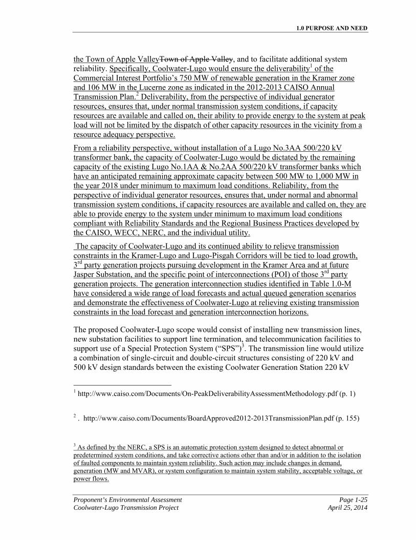
1.0 PURPOSE AND NEED
Proponent’s Environmental Assessment Page 1-25 Coolwater-Lugo Transmission Project April 25, 2014
the Town of Apple ValleyTown of Apple Valley, and to facilitate additional system reliability. Specifically, Coolwater-Lugo would ensure the deliverability1 of the Commercial Interest Portfolio’s 750 MW of renewable generation in the Kramer zone and 106 MW in the Lucerne zone as indicated in the 2012-2013 CAISO Annual Transmission Plan.2 Deliverability, from the perspective of individual generator resources, ensures that, under normal transmission system conditions, if capacity resources are available and called on, their ability to provide energy to the system at peak load will not be limited by the dispatch of other capacity resources in the vicinity from a resource adequacy perspective.
From a reliability perspective, without installation of a Lugo No.3AA 500/220 kV transformer bank, the capacity of Coolwater-Lugo would be dictated by the remaining capacity of the existing Lugo No.1AA & No.2AA 500/220 kV transformer banks which have an anticipated remaining approximate capacity between 500 MW to 1,000 MW in the year 2018 under minimum to maximum load conditions. Reliability, from the perspective of individual generator resources, ensures that, under normal and abnormal transmission system conditions, if capacity resources are available and called on, they are able to provide energy to the system under minimum to maximum load conditions compliant with Reliability Standards and the Regional Business Practices developed by the CAISO, WECC, NERC, and the individual utility.
The capacity of Coolwater-Lugo and its continued ability to relieve transmission constraints in the Kramer-Lugo and Lugo-Pisgah Corridors will be tied to load growth, 3rd party generation projects pursuing development in the Kramer Area and at future Jasper Substation, and the specific point of interconnections (POI) of those 3rd party generation projects. The generation interconnection studies identified in Table 1.0-M have considered a wide range of load forecasts and actual queued generation scenarios and demonstrate the effectiveness of Coolwater-Lugo at relieving existing transmission constraints in the load forecast and generation interconnection horizons.
The proposed Coolwater-Lugo scope would consist of installing new transmission lines, new substation facilities to support line termination, and telecommunication facilities to support use of a Special Protection System (“SPS”)3. The transmission line would utilize a combination of single-circuit and double-circuit structures consisting of 220 kV and 500 kV design standards between the existing Coolwater Generation Station 220 kV
1 http://www.caiso.com/Documents/On-PeakDeliverabilityAssessmentMethodology.pdf (p. 1)
2 . http://www.caiso.com/Documents/BoardApproved2012-2013TransmissionPlan.pdf (p. 155)
3 As defined by the NERC, a SPS is an automatic protection system designed to detect abnormal or predetermined system conditions, and take corrective actions other than and/or in addition to the isolation of faulted components to maintain system reliability. Such action may include changes in demand, generation (MW and MVAR), or system configuration to maintain system stability, acceptable voltage, or power flows.
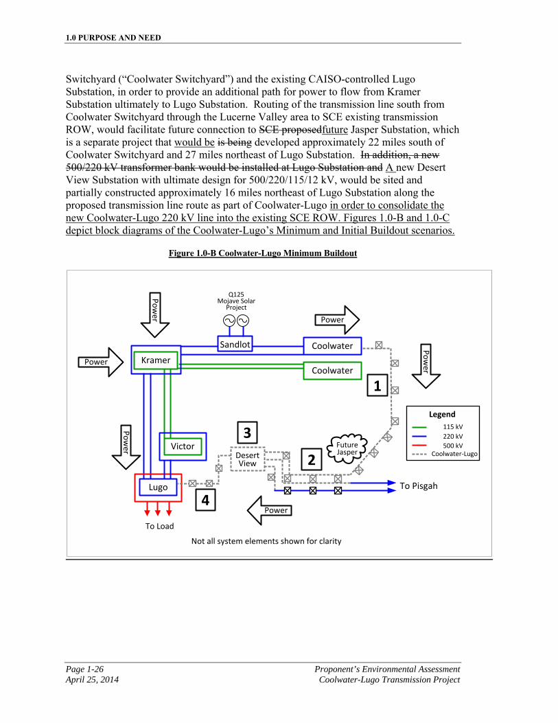
1.0 PURPOSE AND NEED
Page 1-26 Proponent’s Environmental Assessment April 25, 2014 Coolwater-Lugo Transmission Project
Switchyard (“Coolwater Switchyard”) and the existing CAISO-controlled Lugo Substation, in order to provide an additional path for power to flow from Kramer Substation ultimately to Lugo Substation. Routing of the transmission line south from Coolwater Switchyard through the Lucerne Valley area to SCE existing transmission ROW, would facilitate future connection to SCE proposedfuture Jasper Substation, which is a separate project that would be is being developed approximately 22 miles south of Coolwater Switchyard and 27 miles northeast of Lugo Substation. In addition, a new 500/220 kV transformer bank would be installed at Lugo Substation and A new Desert View Substation with ultimate design for 500/220/115/12 kV, would be sited and partially constructed approximately 16 miles northeast of Lugo Substation along the proposed transmission line route as part of Coolwater-Lugo in order to consolidate the new Coolwater-Lugo 220 kV line into the existing SCE ROW. Figures 1.0-B and 1.0-C depict block diagrams of the Coolwater-Lugo’s Minimum and Initial Buildout scenarios.
Figure 1.0-B Coolwater-Lugo Minimum Buildout
CoolwaterKramer
Coolwater
Victor
Lugo
Sandlot
Power
Po
wer
Power
Po
wer
To Load
Po
wer
DesertView
Q125 Mojave Solar
Project
To Pisgah
Not all system elements shown for clarity
Power
1
2
3
4
Legend
115 kV
220 kV
500 kVCoolwater-Lugo
FutureJasper
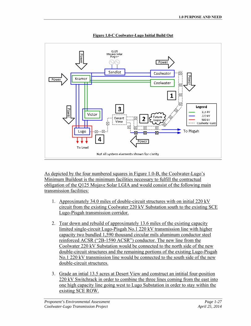
1.0 PURPOSE AND NEED
Proponent’s Environmental Assessment Page 1-27 Coolwater-Lugo Transmission Project April 25, 2014
Figure 1.0-C Coolwater-Lugo Initial Build Out
As depicted by the four numbered squares in Figure 1.0-B, the Coolwater-Lugo’s Minimum Buildout is the minimum facilities necessary to fulfill the contractual obligation of the Q125 Mojave Solar LGIA and would consist of the following main transmission facilities:
1. Approximately 34.0 miles of double-circuit structures with on initial 220 kV circuit from the existing Coolwater 220 kV Substation south to the existing SCE Lugo-Pisgah transmission corridor.
2. Tear down and rebuild of approximately 13.6 miles of the existing capacity limited single-circuit Lugo-Pisgah No.1 220 kV transmission line with higher capacity two bundled 1,590 thousand circular mils aluminum conductor steel reinforced ACSR (“2B-1590 ACSR”) conductor. The new line from the Coolwater 220 kV Substation would be connected to the north side of the new double-circuit structures and the remaining portions of the existing Lugo-Pisgah No.1 220 kV transmission line would be connected to the south side of the new double-circuit structures.
3. Grade an intial 13.5 acres at Desert View and construct an intitial four-position 220 kV Switchrack in order to combine the three lines coming from the east into one high capacity line going west to Lugo Substation in order to stay within the existing SCE ROW.
1.0 PURPOSE AND NEED
Page 1-28 Proponent’s Environmental Assessment April 25, 2014 Coolwater-Lugo Transmission Project
4. Tear down and rebuild of approximately 16.6 miles of the existing capacity limited Lugo-Pisgah No.1 and No.2 220 kV transmission lines with one single circuit 500 kV transmission line, utilizing 2B-2156 ACSR conductor, initially operated at 220 kV from the Desert View 220 kV Switchrack west to Lugo Substation.
However, given the additional large amounts of generation projects in queue in the Kramer System and at Jasper Substation, the need to interconnect additional renewable projects in order to maintain the 33% RPS past the year 2020, the growing electrical demand in the High Desert Area, and the future need for increased system reliability, SCE is proposing to construct the Initial Buildout rather than the Minimum Buildout, in consideration of the long-term planning forecast and in order to minimize the cost, lead time, and environmental disturbance of expected incremental upgrades within the Coolwater-Lugo Project area that are expected to occur within or just beyond the 10-year planning window.
The four numbered squares in Figure 1.0-C depict the facilities that SCE proposes to build as an Initial Buildout.
a. Area “1” in Figure 1.0-C depicts a double-circuit 220 kV line operated in a box-loop configuration, where both sides of the new double-circuit structures would be strung, but operated as a single circuit. Using double-circuit structures and initially stringing both sides would be cheaper and have less environmental disturbance than either initially constructing one single-circuit line and having to build a second separate single-circuit line later, or using double-circuit structures and only initially stringing one side of the towers and having to string the second circuit at a later date. Stringing both sides of the double-circuit towers initially in a box-loop configuration would reduce material purchases and crew mobilizations and would also allow for special conductor phasing to significantly reduce electrical and magnetic fields (“EMF”).
b. Area “2” in Figure 1.0-C would remain the same as the minimum build out.
c. Area “3” in Figure 1.0-C would include the grading of the full 86 a acres at Desert View, instead of the minimum grading of just 13.5 acres, with the constructing of the initial four-position 220 kV Switchrack in order to combine the three lines coming from the east into one high capacity line going to the west to Lugo Substation in order to stay within the existing SCE ROW. Grading of the additional 73.5 acres, 86 acres total, would ensure alignment in grading of all 86 acres
d. Area “4” in Figure 1.0-C would remain the same as the Minimum Buildout.
Table 1.0-O provides the purpose and need justification for each major element of Coolwater-Lugo under the Minimum, Initial, and Full Buildout scenarios.
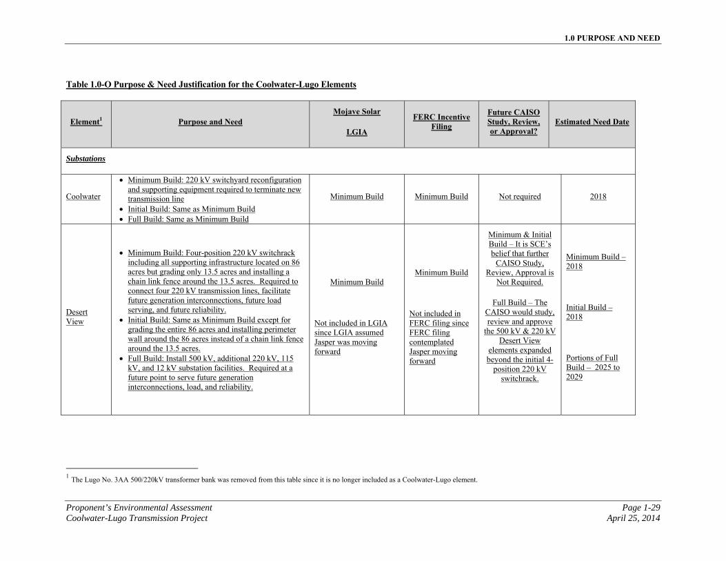
1.0 PURPOSE AND NEED
Proponent’s Environmental Assessment Page 1-29 Coolwater-Lugo Transmission Project April 25, 2014
Table 1.0-O Purpose & Need Justification for the Coolwater-Lugo Elements
Element1 Purpose and Need Mojave Solar
LGIA
FERC Incentive Filing
Future CAISO Study, Review, or Approval?
Estimated Need Date
Substations
Coolwater
Minimum Build: 220 kV switchyard reconfiguration and supporting equipment required to terminate new transmission line
Initial Build: Same as Minimum Build Full Build: Same as Minimum Build
Minimum Build Minimum Build Not required 2018
Desert View
Minimum Build: Four-position 220 kV switchrack including all supporting infrastructure located on 86 acres but grading only 13.5 acres and installing a chain link fence around the 13.5 acres. Required to connect four 220 kV transmission lines, facilitate future generation interconnections, future load serving, and future reliability.
Initial Build: Same as Minimum Build except for grading the entire 86 acres and installing perimeter wall around the 86 acres instead of a chain link fence around the 13.5 acres.
Full Build: Install 500 kV, additional 220 kV, 115 kV, and 12 kV substation facilities. Required at a future point to serve future generation interconnections, load, and reliability.
Minimum Build
Not included in LGIA since LGIA assumed Jasper was moving forward
Minimum Build
Not included in FERC filing since FERC filing contemplated Jasper moving forward
Minimum & Initial Build – It is SCE’s belief that further
CAISO Study, Review, Approval is
Not Required.
Full Build – The CAISO would study, review and approve
the 500 kV & 220 kV Desert View
elements expanded beyond the initial 4-
position 220 kV switchrack.
Minimum Build – 2018
Initial Build – 2018
Portions of Full Build – 2025 to 2029
1 The Lugo No. 3AA 500/220kV transformer bank was removed from this table since it is no longer included as a Coolwater-Lugo element.
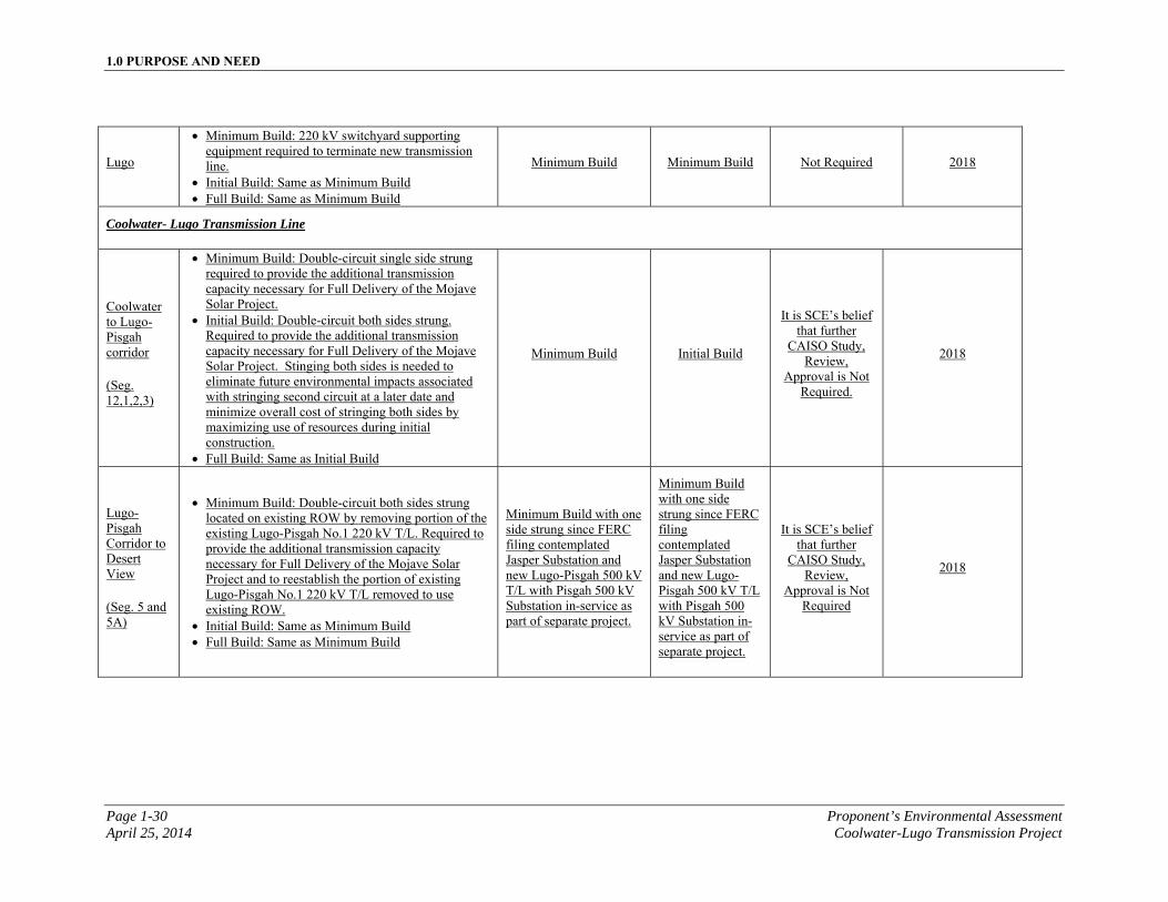
1.0 PURPOSE AND NEED
Page 1-30 Proponent’s Environmental Assessment April 25, 2014 Coolwater-Lugo Transmission Project
Lugo
Minimum Build: 220 kV switchyard supporting equipment required to terminate new transmission line.
Initial Build: Same as Minimum Build Full Build: Same as Minimum Build
Minimum Build Minimum Build Not Required 2018
Coolwater- Lugo Transmission Line
Coolwater to Lugo-Pisgah corridor
(Seg. 12,1,2,3)
Minimum Build: Double-circuit single side strung required to provide the additional transmission capacity necessary for Full Delivery of the Mojave Solar Project.
Initial Build: Double-circuit both sides strung. Required to provide the additional transmission capacity necessary for Full Delivery of the Mojave Solar Project. Stinging both sides is needed to eliminate future environmental impacts associated with stringing second circuit at a later date and minimize overall cost of stringing both sides by maximizing use of resources during initial construction.
Full Build: Same as Initial Build
Minimum Build Initial Build
It is SCE’s belief that further
CAISO Study, Review,
Approval is Not Required.
2018
Lugo-Pisgah Corridor to Desert View
(Seg. 5 and 5A)
Minimum Build: Double-circuit both sides strung located on existing ROW by removing portion of the existing Lugo-Pisgah No.1 220 kV T/L. Required to provide the additional transmission capacity necessary for Full Delivery of the Mojave Solar Project and to reestablish the portion of existing Lugo-Pisgah No.1 220 kV T/L removed to use existing ROW.
Initial Build: Same as Minimum Build Full Build: Same as Minimum Build
Minimum Build with one side strung since FERC filing contemplated Jasper Substation and new Lugo-Pisgah 500 kV T/L with Pisgah 500 kV Substation in-service as part of separate project.
Minimum Build with one side strung since FERC filing contemplated Jasper Substation and new Lugo-Pisgah 500 kV T/L with Pisgah 500 kV Substation in-service as part of separate project.
It is SCE’s belief that further
CAISO Study, Review,
Approval is Not Required
2018
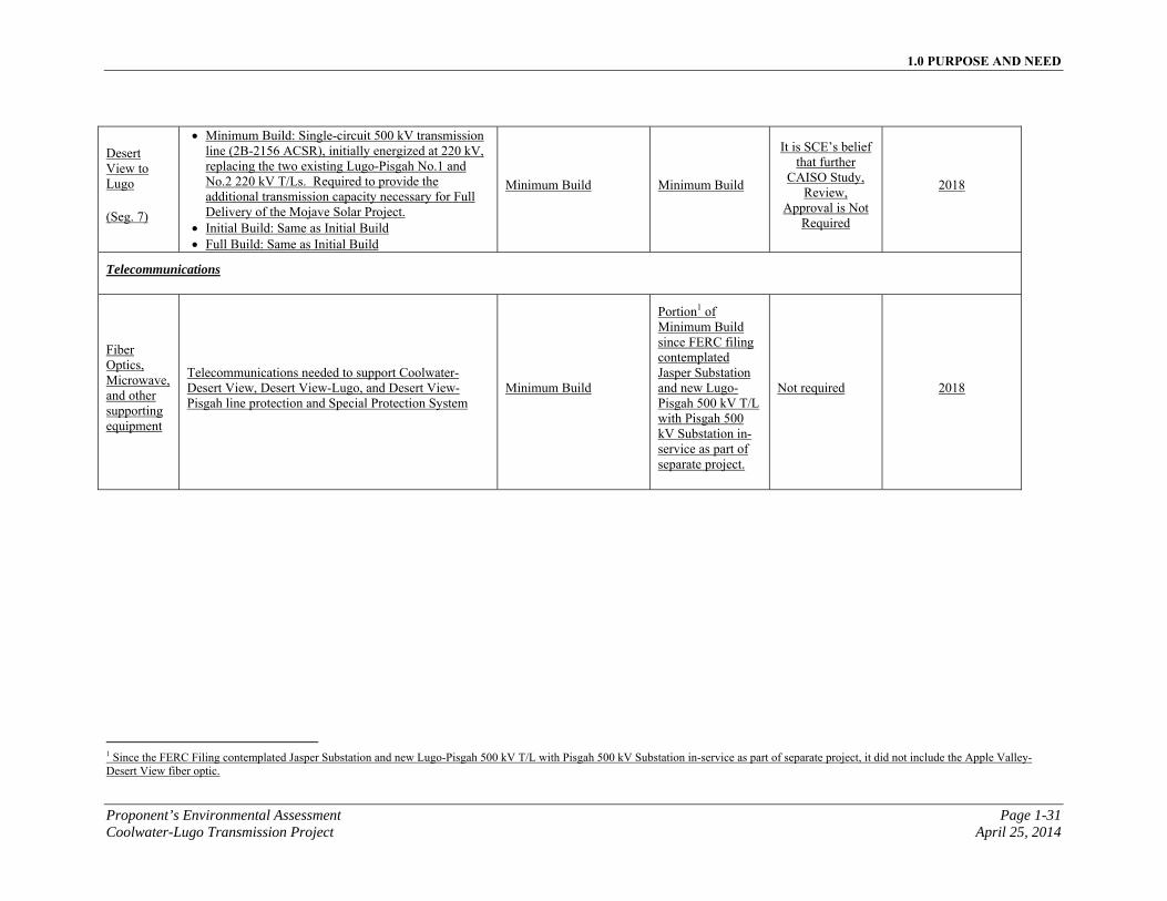
1.0 PURPOSE AND NEED
Proponent’s Environmental Assessment Page 1-31 Coolwater-Lugo Transmission Project April 25, 2014
Desert View to Lugo
(Seg. 7)
Minimum Build: Single-circuit 500 kV transmission line (2B-2156 ACSR), initially energized at 220 kV, replacing the two existing Lugo-Pisgah No.1 and No.2 220 kV T/Ls. Required to provide the additional transmission capacity necessary for Full Delivery of the Mojave Solar Project.
Initial Build: Same as Initial Build Full Build: Same as Initial Build
Minimum Build Minimum Build
It is SCE’s belief that further
CAISO Study, Review,
Approval is Not Required
2018
Telecommunications
Fiber Optics, Microwave, and other supporting equipment
Telecommunications needed to support Coolwater-Desert View, Desert View-Lugo, and Desert View-Pisgah line protection and Special Protection System
Minimum Build
Portion1 of Minimum Build since FERC filing contemplated Jasper Substation and new Lugo-Pisgah 500 kV T/L with Pisgah 500 kV Substation in-service as part of separate project.
Not required 2018
1 Since the FERC Filing contemplated Jasper Substation and new Lugo-Pisgah 500 kV T/L with Pisgah 500 kV Substation in-service as part of separate project, it did not include the Apple Valley-Desert View fiber optic.
1.0 PURPOSE AND NEED
Page 1-32 Proponent’s Environmental Assessment April 25, 2014 Coolwater-Lugo Transmission Project
This page is intentionally blank
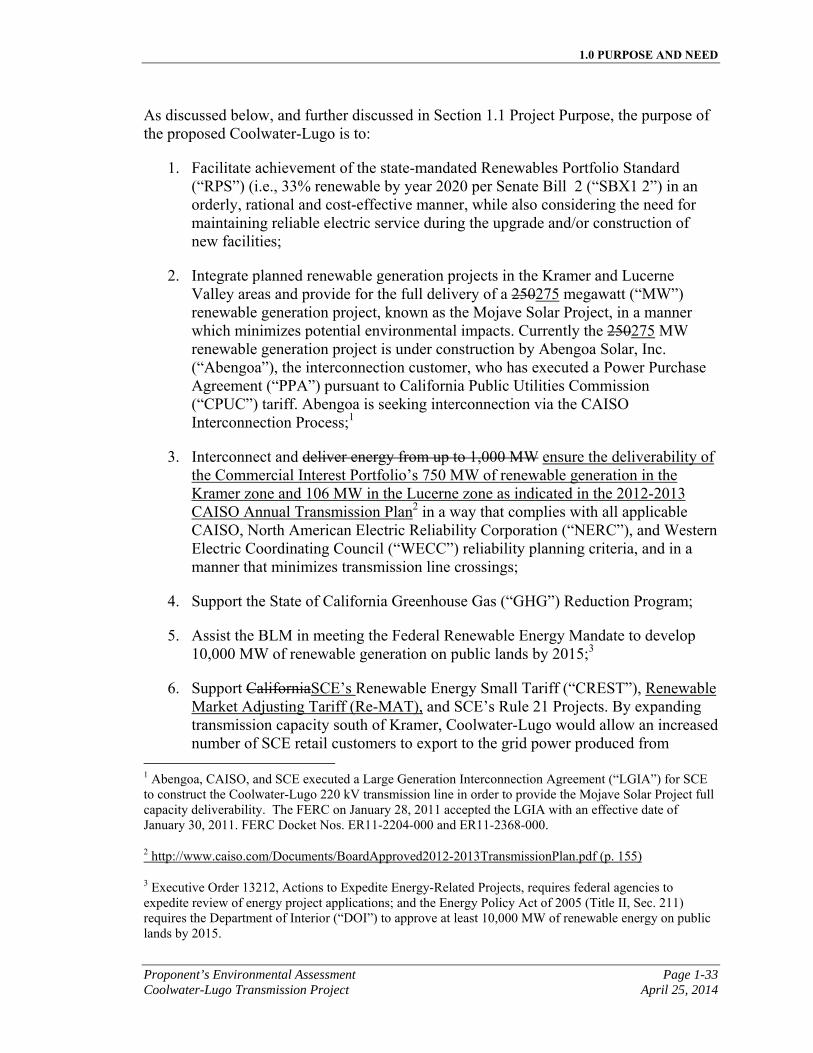
1.0 PURPOSE AND NEED
Proponent’s Environmental Assessment Page 1-33 Coolwater-Lugo Transmission Project April 25, 2014
As discussed below, and further discussed in Section 1.1 Project Purpose, the purpose of the proposed Coolwater-Lugo is to:
1. Facilitate achievement of the state-mandated Renewables Portfolio Standard (“RPS”) (i.e., 33% renewable by year 2020 per Senate Bill 2 (“SBX1 2”) in an orderly, rational and cost-effective manner, while also considering the need for maintaining reliable electric service during the upgrade and/or construction of new facilities;
2. Integrate planned renewable generation projects in the Kramer and Lucerne Valley areas and provide for the full delivery of a 250275 megawatt (“MW”) renewable generation project, known as the Mojave Solar Project, in a manner which minimizes potential environmental impacts. Currently the 250275 MW renewable generation project is under construction by Abengoa Solar, Inc. (“Abengoa”), the interconnection customer, who has executed a Power Purchase Agreement (“PPA”) pursuant to California Public Utilities Commission (“CPUC”) tariff. Abengoa is seeking interconnection via the CAISO Interconnection Process;1
3. Interconnect and deliver energy from up to 1,000 MW ensure the deliverability of the Commercial Interest Portfolio’s 750 MW of renewable generation in the Kramer zone and 106 MW in the Lucerne zone as indicated in the 2012-2013 CAISO Annual Transmission Plan2 in a way that complies with all applicable CAISO, North American Electric Reliability Corporation (“NERC”), and Western Electric Coordinating Council (“WECC”) reliability planning criteria, and in a manner that minimizes transmission line crossings;
4. Support the State of California Greenhouse Gas (“GHG”) Reduction Program;
5. Assist the BLM in meeting the Federal Renewable Energy Mandate to develop 10,000 MW of renewable generation on public lands by 2015;3
6. Support CaliforniaSCE’s Renewable Energy Small Tariff (“CREST”), Renewable Market Adjusting Tariff (Re-MAT), and SCE’s Rule 21 Projects. By expanding transmission capacity south of Kramer, Coolwater-Lugo would allow an increased number of SCE retail customers to export to the grid power produced from
1 Abengoa, CAISO, and SCE executed a Large Generation Interconnection Agreement (“LGIA”) for SCE to construct the Coolwater-Lugo 220 kV transmission line in order to provide the Mojave Solar Project full capacity deliverability. The FERC on January 28, 2011 accepted the LGIA with an effective date of January 30, 2011. FERC Docket Nos. ER11-2204-000 and ER11-2368-000.
2 http://www.caiso.com/Documents/BoardApproved2012-2013TransmissionPlan.pdf (p. 155)
3 Executive Order 13212, Actions to Expedite Energy-Related Projects, requires federal agencies to expedite review of energy project applications; and the Energy Policy Act of 2005 (Title II, Sec. 211) requires the Department of Interior (“DOI”) to approve at least 10,000 MW of renewable energy on public lands by 2015.
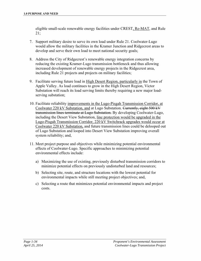
1.0 PURPOSE AND NEED
Page 1-34 Proponent’s Environmental Assessment April 25, 2014 Coolwater-Lugo Transmission Project
eligible small-scale renewable energy facilities under CREST, Re-MAT, and Rule 21;
7. Support military desire to serve its own load under Rule 21. Coolwater-Lugo would allow the military facilities in the Kramer Junction and Ridgecrest areas to develop and serve their own load to meet national security goals;
8. Address the City of Ridgecrest’s renewable energy integration concerns by reducing the existing Kramer-Lugo transmission bottleneck and thus allowing increased development of renewable energy projects in the Ridgecrest area, including Rule 21 projects and projects on military facilities;
9. Facilitate serving future load in High Desert Region, particularly in the Town of Apple Valley. As load continues to grow in the High Desert Region, Victor Substation will reach its load serving limits thereby requiring a new major load-serving substation;
10. Facilitate reliability improvements in the Lugo-Pisgah Transmission Corridor, at Coolwater 220 kV Substation, and at Lugo Substation. Currently, eight 500 kV transmission lines terminate at Lugo Substation. By developing Coolwater-Lugo, including the Desert View Substation, line protection would be upgraded in the Lugo-Pisgah Transmission Corridor, 220 kV Switchrack upgrades would occur at Coolwater 220 kV Substation, and future transmission lines could be delooped out of Lugo Substation and looped into Desert View Substation improving overall system reliability; and,
11. Meet project purpose and objectives while minimizing potential environmental effects of Coolwater-Lugo. Specific approaches to minimizing potential environmental effects include:
a) Maximizing the use of existing, previously disturbed transmission corridors to minimize potential effects on previously undisturbed land and resources;
b) Selecting site, route, and structure locations with the lowest potential for environmental impacts while still meeting project objectives; and,
c) Selecting a route that minimizes potential environmental impacts and project costs.
1.0 PURPOSE AND NEED
Proponent’s Environmental Assessment Page 1-35 Coolwater-Lugo Transmission Project April 25, 2014
1.1 Project Purpose
1.1.1 Compliance with Renewable Portfolio Standard
The California RPS was established in 2002 by SB 1078. The RPS required investor-owned utilities, including retail sellers of electricity such as SCE, to increase their sale of electricity produced by renewable energy sources (such as solar and wind) by at least one percent per year, achieving 20 percent by 2017 (at the latest). These requirements were accelerated by the signing of SBX1 2 by Governor Edmund G. Brown, Jr., requiring 20 percent of retails sales from renewables by the end of 2013, 25 percent by the end of 2016, and a 33 percent requirement being met by the end of 2020.1 In order for investor-owned utilities to satisfy these target goals, new transmission facilities would be required to interconnect remote areas of high renewable generation concentration, and new transmission would be required to eliminate bottlenecks that would preclude delivery of energy produced from these renewable resources to the applicable utility load centers. Coolwater-Lugo is needed to enable California electric utilities to facilitate compliance with the state mandated RPS in a manner that maximizes the use of existing, previously disturbed transmission line right-of-way (“ROW”) in order to minimize potential effects on previously undisturbed land and resources.
Moreover, the California Energy Commission’s (“CEC”) 2011 Integrated Energy Policy Report (“IEPR”) encourages the development of additional transmission infrastructure to interconnect and deliver renewable resources. The IEPR Report identified that the success in meeting the RPS and the GHG Reduction Program is largely dependent upon having the ability to interconnect substantial amounts of new renewable generation. Furthermore it states that the lack of transmission infrastructure to access remote renewable resources is a critical barrier to meeting California’s 2020 electricity and natural gas goals.
1.1.2 Integrate Planned Renewable Generation Resources
Under orders issued pursuant to Sections 210 and 212 of the Federal Power Act (16 U.S. Code §§ 824i and 824k) and interconnection agreements executed pursuant to CAISO Fifth Replacement Electric Tariff, SCE is obligated to interconnect and integrate power generation facilities into its electric system and provide for the level of interconnection service requested.
When an electric generating facility makes an interconnection request, the CAISO evaluates whether transmission line upgrades are needed to safely and reliably satisfy the request. If the CAISO analysis indicates that transmission upgrades are needed, then the necessary upgrades are incorporated into a Generator Interconnection Agreement that is entered into by the applicable interconnection customer(s), the utility (such as SCE), and the CAISO.
1 http://www.energy.ca.gov/portfolio/index.html
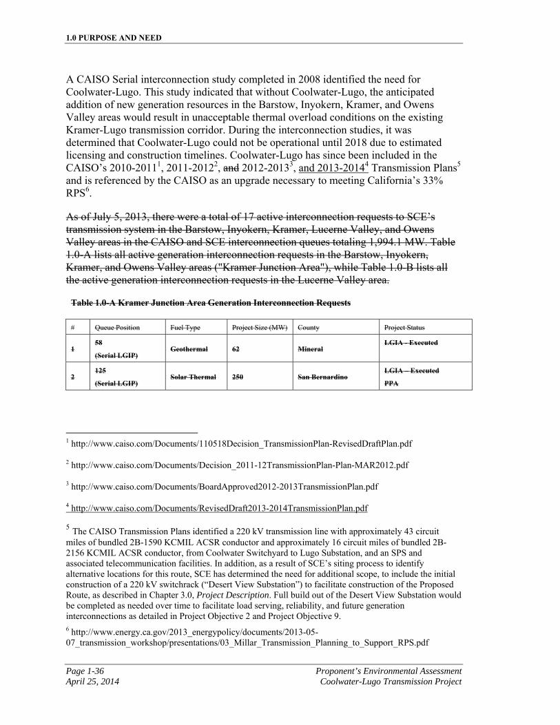
1.0 PURPOSE AND NEED
Page 1-36 Proponent’s Environmental Assessment April 25, 2014 Coolwater-Lugo Transmission Project
A CAISO Serial interconnection study completed in 2008 identified the need for Coolwater-Lugo. This study indicated that without Coolwater-Lugo, the anticipated addition of new generation resources in the Barstow, Inyokern, Kramer, and Owens Valley areas would result in unacceptable thermal overload conditions on the existing Kramer-Lugo transmission corridor. During the interconnection studies, it was determined that Coolwater-Lugo could not be operational until 2018 due to estimated licensing and construction timelines. Coolwater-Lugo has since been included in the CAISO’s 2010-20111, 2011-20122, and 2012-20133, and 2013-20144 Transmission Plans5 and is referenced by the CAISO as an upgrade necessary to meeting California’s 33% RPS6.
As of July 5, 2013, there were a total of 17 active interconnection requests to SCE’s transmission system in the Barstow, Inyokern, Kramer, Lucerne Valley, and Owens Valley areas in the CAISO and SCE interconnection queues totaling 1,994.1 MW. Table 1.0-A lists all active generation interconnection requests in the Barstow, Inyokern, Kramer, and Owens Valley areas ("Kramer Junction Area"), while Table 1.0-B lists all the active generation interconnection requests in the Lucerne Valley area.
Table 1.0-A Kramer Junction Area Generation Interconnection Requests
# Queue Position Fuel Type Project Size (MW) County Project Status
1 58
(Serial LGIP) Geothermal 62 Mineral
LGIA - Executed
2 125
(Serial LGIP) Solar Thermal 250 San Bernardino
LGIA – Executed
PPA
1 http://www.caiso.com/Documents/110518Decision_TransmissionPlan-RevisedDraftPlan.pdf
2 http://www.caiso.com/Documents/Decision_2011-12TransmissionPlan-Plan-MAR2012.pdf
3 http://www.caiso.com/Documents/BoardApproved2012-2013TransmissionPlan.pdf
4 http://www.caiso.com/Documents/RevisedDraft2013-2014TransmissionPlan.pdf
5 The CAISO Transmission Plans identified a 220 kV transmission line with approximately 43 circuit miles of bundled 2B-1590 KCMIL ACSR conductor and approximately 16 circuit miles of bundled 2B- 2156 KCMIL ACSR conductor, from Coolwater Switchyard to Lugo Substation, and an SPS and associated telecommunication facilities. In addition, as a result of SCE’s siting process to identify alternative locations for this route, SCE has determined the need for additional scope, to include the initial construction of a 220 kV switchrack (“Desert View Substation”) to facilitate construction of the Proposed Route, as described in Chapter 3.0, Project Description. Full build out of the Desert View Substation would be completed as needed over time to facilitate load serving, reliability, and future generation interconnections as detailed in Project Objective 2 and Project Objective 9. 6 http://www.energy.ca.gov/2013_energypolicy/documents/2013-05-07_transmission_workshop/presentations/03_Millar_Transmission_Planning_to_Support_RPS.pdf
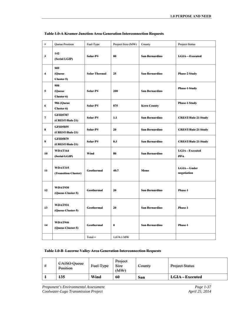
1.0 PURPOSE AND NEED
Proponent’s Environmental Assessment Page 1-37 Coolwater-Lugo Transmission Project April 25, 2014
Table 1.0-A Kramer Junction Area Generation Interconnection Requests
# Queue Position Fuel Type Project Size (MW) County Project Status
3 142
(Serial LGIP) Solar PV 80 San Bernardino
LGIA – Executed
4
909
(Queue
Cluster 5)
Solar Thermal 25 San Bernardino Phase 2 Study
5
950
(Queue
Cluster 6)
Solar PV 200 San Bernardino Phase 1 Study
6 986 (Queue
Cluster 6) Solar PV 875 Kern County
Phase 1 Study
7 GFID5707
(CREST/Rule 21) Solar PV 1.1 San Bernardino CREST/Rule 21 Study
8 GFID5855
(CREST/Rule 21) Solar PV 20 San Bernardino CREST/Rule 21 Study
9 GFID5879
(CREST/Rule 21) Solar PV 0.3 San Bernardino CREST/Rule 21 Study
10 WDAT164
(Serial LGIP) Wind 80 San Bernardino
LGIA - Executed
PPA
11 WDAT315
(Transition Cluster) Geothermal 40.7 Mono
LGIA – Under negotiation
12 WDAT930
(Queue Cluster 5) Geothermal 20 San Bernardino
Phase 1
13 WDAT931
(Queue Cluster 5) Geothermal 20 San Bernardino
Phase 1
14 WDAT946
(Queue Cluster 5) Geothermal 0 San Bernardino
Phase 1
Total = 1,674.1 MW
Table 1.0-B Lucerne Valley Area Generation Interconnection Requests
# CAISO Queue Position Fuel Type
Project Size (MW)
County Project Status
1 135 Wind 60 San LGIA - Executed
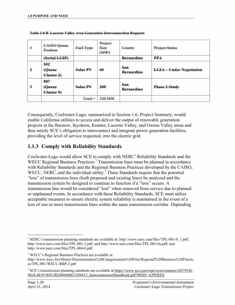
1.0 PURPOSE AND NEED
Page 1-38 Proponent’s Environmental Assessment April 25, 2014 Coolwater-Lugo Transmission Project
Table 1.0-B Lucerne Valley Area Generation Interconnection Requests
# CAISO Queue Position Fuel Type
Project Size (MW)
County Project Status
(Serial LGIP) Bernardino PPA
2 552 (Queue Cluster 2)
Solar PV 60 San Bernardino LGIA – Under Negotiation
3 897 (Queue Cluster 5)
Solar PV 200 San Bernardino Phase 2 Study
Total = 320 MW
Consequently, Coolwater-Lugo, summarized in Section 1.6, Project Summary, would enable California utilities to access and deliver the output of renewable generation projects in the Barstow, Inyokern, Kramer, Lucerne Valley, and Owens Valley areas and thus satisfy SCE’s obligation to interconnect and integrate power generation facilities, providing the level of service requested, into the electric grid.
1.1.3 Comply with Reliability Standards
Coolwater-Lugo would allow SCE to comply with NERC1 Reliability Standards and the WECC Regional Business Practices.2 Transmission lines must be planned in accordance with Reliability Standards and the Regional Business Practices developed by the CAISO, WECC, NERC, and the individual utility.3 These Standards require that the potential “loss” of transmission lines (both proposed and existing lines) be analyzed and the transmission system be designed to continue to function if a “loss” occurs. A transmission line would be considered “lost” when removed from service due to planned or unplanned events. In accordance with these Reliability Standards, SCE must utilize acceptable measures to ensure electric system reliability is maintained in the event of a loss of one or more transmission lines within the same transmission corridor. Depending
1 NERC’s transmission planning standards are available at: http://www.nerc.com/files/TPL-001-0_1.pdf;
http://www.nerc.com/files/TPL-001-2.pdf; and http://www.nerc.com/files/TPL-003-0a.pdf; and http://www.nerc.com/files/TPL-004-0.pdf. 2 WECC’s Regional Business Practices are available at: http://www.wecc.biz/library/Documentation%20Categorization%20Files/Regional%20Business%20Practices/TPL-001-WECC-RBP-2.pdf 3 SCE’s transmission planning standards are available at https://www.sce.com/wps/wcm/connect/c827954f-98c8-4819-965f-f824f466fbb3/030413_InterconnectionHandbook.pdf?MOD=AJPERES.
1.0 PURPOSE AND NEED
Proponent’s Environmental Assessment Page 1-39 Coolwater-Lugo Transmission Project April 25, 2014
on transmission planning studies, these measures may include installation of a SPS,1 construction of additional facility upgrades, or both.
1.1.4 Support California’s Greenhouse Gas Reduction Program
With the signing of Assembly Bill (“AB”) 322, California has embarked on an ambitious program to reduce GHG emissions. The 2006 IEPR Update states that “achieving the state’s RPS goals is an essential component of California’s GHG emission reduction targets.”
Coolwater-Lugo would enable California to integrate renewable resources such as solar and wind, which could help the State of California achieve GHG emissions reduction targets by reducing reliance on energy sources that result in high levels of GHG emissions.
1.1.5 Support Federal Renewable Energy Mandate
Executive Order 13212, Actions to Expedite Energy-Related Projects, requires Federal agencies to expedite review of energy project applications.
The Energy Policy Act of 2005 (Title II, Sec. 211) requires the Department of Interior to approve at least 10,000 MW of renewable energy on public lands by 2015.
1.1.6 Support CREST,Re-MAT, and Rule 21 Projects
Under the CREST, created by California’s AB 1969 and SB 380, and as implemented by the CPUC, SCE is required to purchase power from SCE retail customers who own and operate an eligible renewable generator with a total effective generation capacity of not more than three MW. In addition, Re-MAT implements a renewable resource feed-in tariff program pursuant to California Public Utilities Code (PUC) Section 399.20 and CPUC Decision (D.) 12-05-035, D.13-01-041, and D.13-05-034. Furthermore, SCE customers have the option to generate their own power under SCE’s Rule 21 non-export program.
Since there is more generation than load in the Barstow, Inyokern, Kramer, and Owens Valley areas, any CREST and Re-MAT MW connecting to distribution voltages in these electrical areas would effectively be transferred to the transmission system, flow into Kramer Substation, and would ultimately need to be exported south of Kramer. Furthermore, Rule 21 projects would result in a decrease of local area load which would
1 An SPS is designed to detect abnormal system conditions and take automatic, pre-planned, corrective action (other than the isolation of faulted elements) to provide acceptable system performance. SPS actions may result in reduction in load or generation, or changes in system configuration to maintain system stability, acceptable voltages, or acceptable facility loading. 2 Cal. Health and Safety Code §§ 38500 to 38599 (2006)
1.0 PURPOSE AND NEED
Page 1-40 Proponent’s Environmental Assessment April 25, 2014 Coolwater-Lugo Transmission Project
increase the amount of net generation in this region thereby causing additional power to flow into Kramer Substation that would ultimately need to be exported south. Because the system in the South of Kramer area is already constrained, CREST and Rule 21 projects would further aggravate system reliability caused by the bottleneck associated with the two capacity constrained Kramer-Lugo 220 kV transmission lines. Small projects seeking export under CREST and Rule 21 have therefore been blocked from development and because of their size, have complained about the lack of transmission capacity in this region and their inability to develop.
1.1.7 Support Military Desire to Serve their Load under Rule 21
Several military installations within the Kramer Junction and Ridgecrest areas have expressed a desire to participate in Rule 21 projects in order to serve their site load for national security purposes. As previously stated, Rule 21 projects result in reduced local area load. This condition would cause more power to flow into Kramer Substation, which would ultimately need to be exported south. As Rule 21 projects materialize, an operating procedure to curtail (i.e., turn off) renewable resources may be required. Such a procedure would result in less renewable resources as they are curtailed; thus, adversely impacting the achievement of RPS goals. Coolwater-Lugo would provide additional transmission capacity that would help avoid reducing renewable resource projects, and would also allow military installations to participate in Rule 21 projects and address their national security concerns to serve their load.
1.1.8 Address City of Ridgecrest’s Renewable Integration Concerns
The City of Ridgecrest is concerned about the Kramer-Lugo transmission bottleneck and the impact this constraint is having on their ability to add solar generation in their community, to support local military installation Rule 21 projects, and to create jobs. On May 10, 2011, SCE explained the Kramer-Lugo bottleneck constraint to the Ridgecrest City Council Planning Commission and proposed Coolwater-Lugo as a means to help create additional transmission capacity1.
1.1.9 Facilitate Future Load Serving in the High Desert Apple Valley Region, particularly the Town of Apple Valley
Apple Valley load is currently served out of SCE’s Victor Substation, located in the City of Victorville, which is the only major load-serving substation providing service to the entire High Desert Region. As load continues to grow in the High Desert Region, Victor Substation will reach its load serving limits thereby requiring a new major load-serving substation. A new multipurpose 500/220/115/12 kV substation (“Desert View Substation”) placed in an area with significant load, such as the growing Apple Valley load area, would provide the required load-serving relief to Victor Substation. The proposed Desert View Substation, to be licensed as part of Coolwater-Lugo, is
1 http://ci.ridgecrest.ca.us/doclib/lib/Meetings/PC/Minutes/2011/5-10-11%20PC%20Minutes.pdf
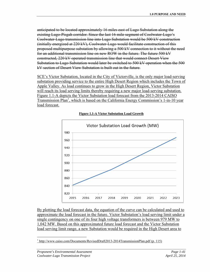
1.0 PURPOSE AND NEED
Proponent’s Environmental Assessment Page 1-41 Coolwater-Lugo Transmission Project April 25, 2014
anticipated to be located approximately 16 miles east of Lugo Substation along the existing Lugo-Pisgah corridor. Since the last 16 mile segment of Coolwater-Lugo’s Coolwater-Lugo transmission line into Lugo Substation would be 500 kV construction (initially energized at 220 kV), Coolwater-Lugo would facilitate construction of this proposed multipurpose substation by allowing a 500 kV connection to it without the need for an additional transmission line on new ROW in the future. The future 500 kV constructed, 220 kV operated transmission line that would connect Desert View Substation to Lugo Substation would later be switched to 500 kV operation when the 500 kV section of Desert View Substation is built out in the future.
SCE’s Victor Substation, located in the City of Victorville, is the only major load-serving substation providing service to the entire High Desert Region which includes the Town of Apple Valley. As load continues to grow in the High Desert Region, Victor Substation will reach its load serving limits thereby requiring a new major load-serving substation. Figure 1.1-A depicts the Victor Substation load forecast from the 2013-2014 CAISO Transmission Plan1, which is based on the California Energy Commission’s 1-in-10 year load forecast.
Figure 1.1-A Victor Substation Load Growth
By plotting the load forecast data, the equation of the curve can be calculated and used to approximate the load forecast in the future. Victor Substation’s load serving limit under a single contingency on one of its four high voltage transformers is between 979 MW to 1,042 MW. Based on this approximated future load forecast and the Victor Substation load serving limit range, a new Substation would be required in the High Desert area to
1 http://www.caiso.com/Documents/RevisedDraft2013-2014TransmissionPlan.pdf (p. 115)
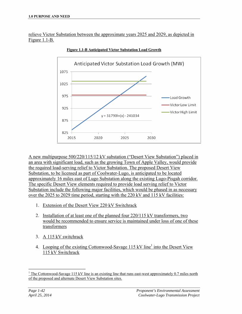
1.0 PURPOSE AND NEED
Page 1-42 Proponent’s Environmental Assessment April 25, 2014 Coolwater-Lugo Transmission Project
relieve Victor Substation between the approximate years 2025 and 2029, as depicted in Figure 1.1-B.
Figure 1.1-B Anticipated Victor Substation Load Growth
A new multipurpose 500/220/115/12 kV substation (“Desert View Substation”) placed in an area with significant load, such as the growing Town of Apple Valley, would provide the required load-serving relief to Victor Substation. The proposed Desert View Substation, to be licensed as part of Coolwater-Lugo, is anticipated to be located approximately 16 miles east of Lugo Substation along the existing Lugo-Pisgah corridor. The specific Desert View elements required to provide load serving relief to Victor Substation include the following major facilities, which would be phased in as necessary over the 2025 to 2029 time period, starting with the 220 kV and 115 kV facilities:
1. Extension of the Desert View 220 kV Switchrack
2. Installation of at least one of the planned four 220/115 kV transformers, two would be recommended to ensure service is maintained under loss of one of these transformers
3. A 115 kV switchrack
4. Looping of the existing Cottonwood-Savage 115 kV line1 into the Desert View 115 kV Switchrack
1 The Cottonwood-Savage 115 kV line is an existing line that runs east-west approximately 0.7 miles north of the proposed and alternate Desert View Substation sites.
1.0 PURPOSE AND NEED
Proponent’s Environmental Assessment Page 1-43 Coolwater-Lugo Transmission Project April 25, 2014
5. Looping of the existing Apple Valley-Cottonwood-Pluess-Savage 115 kV line1 into the Desert View 115 kV Switchrack
6. Installation of at least one of the planned four 115/12 kV transformers
7. A 12 kV switchrack
8. One or more 12 kV distribution lines from the Desert View 12 kV Switchrack into the nearby neighborhood surrounding Desert View Substation
Once the Desert View 115 kV Switchrack is in place, the Cottonwood-Savage and Apple Valley-Cottonwood-Pluess-Savage 115kV lines would be looped into the 115 kV Switchrack allowing Desert View to serve the load on these lines that was previously being served from Victor Substation. In addition, the future Desert View 12 kV Switchrack and future 12 kV distribution lines out of Desert View would serve local area load of the nearby expanding community.
Furthermore, since the last 16-mile segment of Coolwater-Lugo’s Coolwater-Lugo transmission line into Lugo Substation would be 500 kV single circuit transmission line, with 2B-2156 ACSR conductor(initially energized at 220 kV), Coolwater-Lugo would facilitate construction of this proposed multipurpose substation by allowing a 500 kV connection to it without the need for an additional transmission line on new ROW in the future. The future 500 kV constructed, 220 kV operated transmission line that would connect Desert View Substation to Lugo Substation would later be switched to 500 kV operation when the 500 kV section of Desert View Substation is built out in the future.
1.1.10 Facilitate Reliability Improvements at Lugo Substation in the Lugo-Pisgah Transmission Corridor and at the Coolwater and Lugo Substations
Currently, eight 500 kV transmission lines terminate into SCE’s Lugo Substation. Coolwater-Lugo would facilitate construction of a multipurpose 500/220/115/12 kV Desert View Substation which would allow future 500 kV transmission lines to be delooped out of Lugo Substation thus reducing the number of 500 kV transmission lines terminating at Lugo Substation and thereby improving overall system reliability.
In addition, a SPS is currently required to maintain loadings to within emergency limits under loss of either the Lugo No.1 or No.2 500/220 kV transformer banks, as well as maintain system stability under the loss of both the Lugo No.1 and No.2 500/220 kV transformer banks. Under loss of a single Lugo 500/220 kV transformer bank, the current SPS automatically disconnects (curtails) up to 850 MW of non-renewable resources and under loss of both Lugo 500/220 kV transformer banks, the SPS automatically disconnects (curtails) a significant amount of renewable and non-renewable generation in
1 The Apple Valley-Cottonwood-Pluess-Savage 115 kV line is an existing line that runs east-west approximately 0.1 miles south of the proposed and alternate Desert View Substation sites.
1.0 PURPOSE AND NEED
Page 1-44 Proponent’s Environmental Assessment April 25, 2014 Coolwater-Lugo Transmission Project
the Barstow, Daggett, Inyokern, and Kramer areas to maintain system reliability and stability. As part of Coolwater-Lugo, a new Lugo No.3 500/220 kV transformer bank would be installed at Lugo Substation, thus reducing the severity under loss of a single Lugo 500/220 kV transformer bank and loss of both Lugo 500/220 kV transformer banks and would reduce the amount of Barstow, Inyokern, and Kramer area generation that needs to be curtailed during this type of event, thus increasing overall system reliability and stability.
Furthermore, this new Lugo No.3 500/220 kV transformer bank will also be required to handle the additional 1,000 MW of system capacity Coolwater-Lugo will provide. Coolwater-Lugo will create a new transmission path from Kramer to Lugo Substation and this additional power will need to be stepped-up from 220 kV to 500 kV in order to be delivered to utility load centers. Since the existing Lugo No.1AA and No.2AA 500/220 kV transformers do not have sufficient capability to handle 1,000 additional MW, a third Lugo 500/220 kV transformer will need to be installed as part of Coolwater-Lugo to avoid base case thermal overloads.
The existing Lugo-Pisgah No.1 and No.2 220 kV transmission lines currently have line protection that meets existing CAISO, NERC, and WECC reliability criteria, but which is not aligned with SCE’s current line protection standards. Since Coolwater-Lugo would tear down and rebuild approximately 29.1 miles of the Lugo-Pisgah No. 1 220 kV line and also tear down approximately 16.0 miles of the existing Lugo-Pisgah No.2 220 kV line, the line protection from Lugo to Pisgah Substations will need to be upgraded to current SCE standards, which will reduce fault clearing times and improve overall system reliability. Specifically, the existing directional and ground-over-current and step distance protection provided by the existing electromechanical relays on the existing Lugo-Pisgah No.1 and No.2 220 kV lines would be replaced by G.E. L90 and SEL-311L relays with new telecom circuits to provide high speed fault clearing. High speed fault clearing helps to reduce damage to power system equipment, injury to SCE personnel and the public, and extended and widespread outages because the faults are detected and isolated more quickly thus minimize their effect on the system.
The Coolwater 220 kV Switchrack is currently a radial facility not under CAISO control. Construction of Coolwater-Lugo would convert the Coolwater 220 kV Switchrack from a radial facility to a network facility, which would then be under CAISO control. The Coolwater-Lugo work at the Coolwater 220 kV Switchrack would include augmenting the existing disconnect switches on switch rack positions 1, 3, and 6 with circuit breakers in order to isolate faults on those positions from affecting the rest of the Switchrack. Adding circuit breakers to these rack positions would convert them to “double bus double breaker” positions, which is SCE’s 220 kV design standard. This arrangement ensures reliability is maintained under outage conditions (forced outage or during maintenance) since it allows for the loss of equipment connected to the substation without affecting all other facilities connected to the substation during such an outage condition. These upgrades would increase the reliability of the Coolwater 220 kV Switchrack in its new network configuration, would simplify future additions, minimize loss of station capacity during forced or planned outages, and improve the selectivity of the system protection.
1.0 PURPOSE AND NEED
Proponent’s Environmental Assessment Page 1-45 Coolwater-Lugo Transmission Project April 25, 2014
Moreover, there are currently eight 500 kV transmission lines that terminate at SCE’s Lugo Substation. Per the CAISO’s 2010-20111 and 2011-20122 Transmission Plans, loss of the entire Lugo 500/220 kV Substation would cause the north of Lugo system to be unstable. To restore system synchronism, extensive generation tripping in the North of Lugo area and load tripping in the LA Basin would be required. Coolwater-Lugo would facilitate construction of a multipurpose 500/220/115/12 kV Desert View Substation which would allow future 500 kV transmission lines to be delooped out of Lugo Substation thus reducing the number of 500 kV transmission lines terminating at Lugo Substation. This would allow 500 kV system connections to remain which would result in improving overall system reliability by reducing the amount of generation and load that would be need to be tripped under the loss of Lugo Substation.
1.1.11 Meet Project Purpose & Objectives while Minimizing Environmental Effects
In compliance with the California Environmental Quality Act (“CEQA”) and the National Environmental Policy Act (“NEPA”), Coolwater-Lugo includes and analyzes site and route alternatives that meet the project purpose and objectives while minimizing potential environmental effects. Specific approaches to minimizing environmental effects include:
a) Maximizing the use of existing, previously disturbed corridors to minimize potential effects on previously undisturbed land and resources;
b) Selecting site, route, and structure locations with the lowest potential for environmental impacts while still meeting project objectives; and,
c) Selecting site, route, and structure locations that minimize potential environmental impacts and project costs.
1.2 Project Need
Coolwater-Lugo is needed to interconnect and deliver energy from renewable resources located in the Barstow, Inyokern, Kramer, Lucerne Valley, and Owens Valley areas in a way that complies with all applicable NERC/WECC Planning Standards. All new generation interconnection requests are shown in Tables 1.0-A and 1.0-B. The interconnection studies conducted as mandated by the CAISO Large Generator Interconnection Procedures (“LGIP”) and SCE’s Wholesale Distribution Access Tariff (“WDAT”) have determined that the existing 220 kV transmission lines which connect SCE’s Kramer Substation with SCE’s Lugo Substation are inadequate to provide for the level of service requested by new planned generation interconnections.
1 http://www.caiso.com/Documents/110518Decision_TransmissionPlan-RevisedDraftPlan.pdf
2 http://www.caiso.com/Documents/Decision_2011-12TransmissionPlan-Plan-MAR2012.pdf
1.0 PURPOSE AND NEED
Page 1-46 Proponent’s Environmental Assessment April 25, 2014 Coolwater-Lugo Transmission Project
The studies identified that without transmission upgrades, the inclusion of additional generation resources in the Barstow, Inyokern, Kramer, and Owens Valley areas would result in unacceptable thermal overload conditions on the existing Kramer-Lugo No.1 and No.2 220 kV transmission lines due to existing facility limitations. The conclusion of the studies was that these two transmission lines would present a bottleneck that would limit the amount of generation output from the new generation resources to be located in SCE’s Kramer Junction area that can be delivered to the utility load centers. In addition, generation pursuing development in the Lucerne Valley area would face a similar bottleneck since the existing Lugo-Pisgah No.1 220 kV transmission line that passes through this area is composed of 605 thousand circular mils (“kcmil”) aluminum conductor steel reinforced (“ACSR”) conductor with no emergency capability due to line clearance and would be unable to support the 320 MW of queued generation in the Lucerne Valley area or provide sufficient capacity to support the proposed Coolwater-Lugo 220 kV transmission line. In addition, generation pursuing development in the Lucerne Valley area would face a similar bottleneck since the existing Lugo-Pisgah No.1 220 kV transmission line that passes through this area is composed of 605 kcmil ACSR conductor with no emergency capability due to line clearance and would be unable to support the 260 MW of queued generation in the Lucerne Valley area along with existing resources utilizing the transmission line or provide sufficient capacity to support the proposed Coolwater-Lugo 220 kV transmission line.
In order for investor-owned utilities, including retail sellers of electricity such as SCE, to satisfy the RPS goals to increase their sale of electricity produced by renewable energy sources by at least one percent per year, achieving 33 percent by 2020, new transmission facilities would be required to interconnect remote areas of high renewable generation concentration and new transmission would be required to eliminate bottlenecks that would preclude delivery of energy produced from these renewable resources to the utility load centers. The generation interconnection studies identified a transfer capability bottleneck associated with the two Kramer-Lugo 220 kV transmission lines and the existing Lugo-Pisgah No.1 220 kV transmission line which would jeopardize new renewable energy project development.
The state-mandated RPS by definition is based on the actual MW capacity sale. The identified transfer capability bottleneck south of SCE’s Kramer Substation and bottleneck in the Lucerne Valley area prevent the sale of the renewable power to customers. To achieve the mandated RPS goals, Coolwater-Lugo is needed to remove the bottleneck limitations and to increase transfer capability from renewable resources into customer areas by creating a new transmission path from Kramer to Lugo Substations and by rebuilding a portion of the existing Lugo-Pisgah No.1 220 kV transmission line from the Lucerne Valley area west to Lugo Substation. Without Coolwater-Lugo, the new generation located in the Barstow, Inyokern, Kramer, Lucerne Valley, and Owens Valley areas could not be deemed deliverable and would be subjected to significant curtailment to avoid overloading the two existing Kramer-Lugo 220 kV transmission lines and the existing Lugo-Pisgah No.1 220 kV transmission line and avoid system stability issues identified in System Impact Studies.
1.0 PURPOSE AND NEED
Proponent’s Environmental Assessment Page 1-47 Coolwater-Lugo Transmission Project April 25, 2014
1.3 Basic Objectives
CEQA (Pub. Res. Code § 21000, et seq.) and Section 15126.6 (a) of the CEQA Guidelines1 require the consideration of a reasonable range of alternatives to a proposed project, or the location of a proposed project, that would feasibly attain most of the basic objectives of the project but would avoid or substantially lessen any of the significant effects of the project. Section 15126.6 (a) of the CEQA Guidelines also requires that the comparative merits of the alternatives be evaluated. In order to develop a reasonable range of alternatives, Section 15124(b) of the CEQA Guidelines requires that a clearly written statement of objectives be prepared for a proposed project that demonstrates the objectives sought to be achieved by the project and includes the underlying purpose of the project. The range of potential alternatives selected for evaluation shall “include those that could feasibly accomplish most of the basic objectives of the project and could avoid or substantially lessen one or more of the significant effects.”2 In addition to the purposes described in the section 1.1 above, SCE has identified the following objectives for meeting Coolwater-Lugo’s purpose and need described in this chapter:
1. Facilitate SCE and other California utilities achievement achieving and maintaining of California’s RPS in an expedited manner;
2. Provide transmission facilities identified as necessary for the full delivery of 1) a 250 275 MW renewable generation project located in the Barstow area; 2) future generation resources in the Barstow, Inyokern, Kramer, Lucerne Valley/future Jasper Substation, Town of Apple Valley, and Owens Valley areas;
3. Comply with all applicable reliability planning criteria required by the CAISO, the NERC, and the WECC;
4. Support California’s GHG Reduction Program;
5. Support BLM compliance with the Federal Renewable Energy Mandate;
6. Provide transmission facilities in a timely manner that would facilitate the interconnection of CREST, Re-MAT, and Rule 21 projects;
7. Provide transmission facilities that facilitate the Department of Defense meeting their Energy Mandate of producing or procuring 25% of their total energy from renewable energy sources beginning in 2025 as outlined under the National Defense Authorization Act of 2010;3
8. Address transmission capacity concerns from the City of Ridgecrest; 1 See Cal. Code Regs., tit. 14, §15000, et seq.
2 Cal. Code Regs., tit. 14, §15126.6(c).
3 See http://www.govenergy.com/2010/Files/Presentations/Renewables/2010_GovEnergy_Tindal.pdf
1.0 PURPOSE AND NEED
Page 1-48 Proponent’s Environmental Assessment April 25, 2014 Coolwater-Lugo Transmission Project
9. License a new multipurpose 500/220/115/12 kV Desert View Substation southeast of the Town of Apple Valley to facilitate load serving, reliability, and future generation interconnections;1
10. Construct facilities in an orderly, rational, and cost-effective manner to maintain reliable electric service and by minimizing service interruptions during construction;
11. Minimize potential environmental impacts through selection of transmission routes and substation site locations; including maximizing the use of existing transmission corridors in order to minimize potential effects on previously undisturbed land and resources2, and where existing ROW is not available, utilize the shortest route that minimizes potential environmental impacts;
12. Meet project needs in a cost-effective and timely manner; and,
13. Design and construct the project in conformance with SCE's current engineering, design, and construction standards for substation, transmission, subtransmission, and distribution system projects.
These objectives have guided SCE in developing a range of reasonable alternatives to Coolwater-Lugo, or to the location of Coolwater-Lugo, which would feasibly attain most of the basic project objectives.
1.4 Electrical System Alternatives
System alternatives were developed as part of the serial and cluster generation interconnection study processes. This section describes the process SCE used to develop the system alternatives for Coolwater-Lugo and to select the system alternative for Coolwater-Lugo for recommendation to the CPUC and the BLM. This section provides a description of each system alternative (including the No Project Alternative) and discusses the ability of each of these system alternatives to meet Project objectives, purpose, and need. Also included is the rationale for either eliminating an alternative or carrying it forward. Substation site and transmission route alternatives are discussed in
1 The proposed Desert View Substation would be initially constructed with only the facilities needed to support the transmission line from Coolwater to Lugo. Similar to SCE’s Antelope Substation and Windhub Substation, SCE is seeking to license the full build out of Desert View Substation, which would include 500/220/115/12 kV facilities needed for anticipated load serving in the High Desert Region, particularly the Town of Apple Valley, reliability, and future generation interconnection purposes.
2 See Garamendi Principles (Senate Bill 2431, Stats. 1988, Ch. 1457) regarding State transmission siting policies, including; 1) encourage the use of existing rights-of-way by upgrading existing transmission facilities where technically and economically justifiable; 2) when construction of new transmission lines is required, encourage expansion of existing right-of-way, when technically and economically feasible; 3) provide for the creation of new rights-of-way when justified by environmental, technical, or economic reasons as determined by the appropriate licensing agency; 4) where there is a need to construct additional transmission capacity seek agreement among all interested utilities on the efficient use of that capacity.
1.0 PURPOSE AND NEED
Proponent’s Environmental Assessment Page 1-49 Coolwater-Lugo Transmission Project April 25, 2014
Chapter 2. CEQA does not require in-depth analysis of all potential system alternatives, but specifies that a reasonable range of system alternatives be considered and evaluated that will foster informed decision making and public participation.1
This section begins with a description of the approach to the initial system alternatives selection, discusses requirements of CEQA and NEPA, and then provides descriptions of system alternatives eliminated and retained for evaluation in this Proponent’s Environmental Assessment (“PEA”). While the CAISO is responsible for providing open and non-discriminatory access to the CAISO controlled Grid in California, the CPUC retains exclusive jurisdiction over the siting of CAISO approved transmission projects within the State of California and is the lead agency with respect to such project elements within California under CEQA. Therefore, in the Application of which this PEA is a part, SCE seeks from the CPUC a Certificate of Public Convenience and Necessity (“CPCN”) in accordance with CPUC General Order 131-D. If approved by the CPUC, the CPCN would identify the substation site and transmission route for Coolwater-Lugo, based on the environmental review of SCE’s site and route alternatives, as required by CEQA, and would authorize construction of Coolwater-Lugo (including any modifications to the project approved by the CPUC), consistent with Public Utilities Code Section 1001. This PEA includes a detailed environmental analysis of SCE’s Coolwater-Lugo, together with other information required by CPUC rules, in order to assist the CPUC in preparing its Initial Study of Coolwater-Lugo pursuant to CEQA. Also, since most of the Project Study Area is located on land under the jurisdiction of the BLM, SCE would need to file a ROW application separately with the BLM and obtain a permit to construct from the BLM.
Based on SCE’s evaluation of Coolwater-Lugo’s basic objectives and its potentially significant environmental effects, the principal Project system alternatives SCE has considered and evaluated below are:
▪ System Alternative 1 – Coolwater-Pisgah 220 kV Transmission Line
▪ System Alternative 2 – Rebuilding the Existing Kramer-Lugo 220 kV Transmission Lines
▪ System Alternative 3 – Reconductoring the Existing Kramer-Lugo 220 kV Transmission Lines
▪ System Alternative 4 – Kramer-Lugo No.3 220 kV Transmission Line
▪ System Alternative 5 – Kramer-Llano 500 kV Transmission Line
▪ System Alternative 6 – Kramer-Llano 500 kV Transmission Line and Rebuild of Lugo-Pisgah No.1 220 kV Transmission Line
1 See CEQA Guidelines § 15126.6(a).
1.0 PURPOSE AND NEED
Page 1-50 Proponent’s Environmental Assessment April 25, 2014 Coolwater-Lugo Transmission Project
▪ System Alternative 7 – AV Clearview Transmission Proposal – Baseline Case
▪ System Alternative 8 – AV Clearview Transmission Proposal – Expanded Case
▪ System Alternative 9 - No Project Alternative
1.4.1 System Alternative 1 – Coolwater-Pisgah 220 kV Transmission Line
Description: A Coolwater-Pisgah 220 kV transmission line would require the acquisition of new ROW and the construction of approximately 28 miles of new double-circuit single-strung 220 kV transmission line from the existing Coolwater 220 kV Switchyard, located in Daggett, to Pisgah Substation, which is located east of Newberry Springs. This new Coolwater to Pisgah 220 kV transmission line path would redirect a portion of the power from Kramer Substation and the Coolwater 220 kV Switchyard southeast to Pisgah Substation and then west to Lugo Substation. This new transmission path would attempt to off-load the existing transmission capacity limited Kramer-Lugo No.1 and No.2 220 kV transmission lines in an effort to create additional transmission capacity.
Project Objectives, Feasibility, and Environmental Considerations: Due to the increased electrical path impedance associated with rerouting power from Kramer Substation and the Coolwater 220 kV Switchyard all the way east to Pisgah Substation and then back west to Lugo Substation, a Coolwater-Pisgah 220 kV transmission line would not alleviate the Kramer-Lugo No.1 and No.2 220 kV transmission line constraints. In fact, if additional resources are interconnected to the Pisgah Substation, this alternative would result in additional flows on the already constrained Kramer-Lugo 220 kV transmission lines.
Because a Coolwater-Pisgah 220 kV transmission line would not eliminate the existing Kramer to Lugo transmission capacity bottleneck, this alternative would not provide the additional transmission system capacity to interconnect and integrate new generation resources that ultimately require transmission capacity south of Kramer and allow compliance with California’s RPS (Objective 1 – Facilitate SCE and other California utilities achievement of California’s RPS). Alternative 1 would not provide the necessary transmission capacity to fully integrate the 250275 MW generation project seeking interconnection in the Barstow area and additional future generation resources in the Barstow, Inyokern, Kramer, Lucerne Valley, and Owens Valley areas (Objective 2 – Provide transmission that would facilitate the full delivery a 250 275 MW renewable generation project and future generation resources in the Barstow, Inyokern, Kramer, Lucerne Valley/future Jasper Substation, Town of Apple Valley, and Owens Valley areas) or facilitate the interconnection of CREST, Re-MAT, and Rule 21 projects (Objective 6 – Facilitate CREST, Re-MAT, and Rule 21 projects). In addition, this alternative does not facilitate the Department of Defense meeting their Energy Mandate of producing or procuring 25% of their total energy from renewable energy sources beginning in 2025 (Objective 7 – Facilitate the Department of Defense meeting their Energy Mandate) or address transmission capacity concerns from the City of Ridgecrest
1.0 PURPOSE AND NEED
Proponent’s Environmental Assessment Page 1-51 Coolwater-Lugo Transmission Project April 25, 2014
(Objective 8 – Address transmission capacity concerns from the City of Ridgecrest). Finally, this alternative does not site a new Desert View Substation to facilitate load serving, reliability, and future generation interconnections (Objective 9 – Site a new multipurpose substation to facilitate load serving, reliability, and future generation interconnections provide reliability and support load growth in the Apple Valley area). Because System Alternative 1 fails to achieve most of the basic Coolwater-Lugo objectives, it was eliminated from further consideration.
1.4.2 System Alternative 2 – Rebuilding the Existing Kramer-Lugo 220 kV Transmission Lines
Description: Rebuilding the existing 220 kV lines between the existing Kramer and Lugo Substations would involve tearing down and removing the existing 220 kV facilities and replacing them with higher capacity 220 kV or 500 kV facilities. Rebuilding the existing Kramer-Lugo 220 kV lines with 220 kV facilities would not involve the expansion of Kramer Substation and would be developed within existing ROW. However, rebuilding the Kramer-Lugo 220 kV lines with 500 kV facilities would require approximately 92 additional acres to accommodate for the full build-out of a standard SCE designed 500/220 kV substation. Facilities to support a new Kramer-Lugo 500 kV transmission line would require a 500 kV operating bus, a 500/220 kV transformer bank, a Mechanical Electrical Equipment Room (“MEER”), and the installation of additional ancillary equipment including but not limited to circuit breakers, disconnect switches, conductor, and system protection. The acquisition of new ROW around Kramer Substation and Lugo Substation would also be required to route the new 500 kV line from the existing Kramer-Lugo corridor to the 500 kV buses at Kramer and Lugo Substations.
Project Objectives, Feasibility, and Environmental Considerations: Rebuilding the Kramer-Lugo 220 kV transmission lines with higher capacity 220 kV or 500 kV facilities would require the complete removal of the existing 220 kV facilities (approximately 48 miles) and the installation of new higher capacity 220 kV or 500 kV facilities. However, SCE is precluded from taking a long-term outage on both the Kramer-Lugo No.1 and No.2 220 kV transmission lines in order to rebuild them due to RPS, financial, reliability, and load serving concerns.
Under the outage of both the Kramer-Lugo No.1 and No.2 220 kV transmission lines, there would be insufficient transmission capacity for the existing 1,7291 MW of Kramer area generation. Consequently, significant amounts of the Kramer area generation would need to be curtailed to maintain a balance between local area load and generation. Since most generation in the Kramer area is renewable in nature, this prolonged curtailment of renewable resources would negatively impact SCE’s RPS requirements. Moreover, over 900 MW of generation resources in the North of Kramer area have qualified facilities contracts in place with SCE and SCE could be required to pay these generators for lost production during a prolonged outage, which would cause an unnecessary financial
1 http://www.caiso.com/Documents/AppendixABoardApproved2012-2013TransmissionPlan.pdf
1.0 PURPOSE AND NEED
Page 1-52 Proponent’s Environmental Assessment April 25, 2014 Coolwater-Lugo Transmission Project
burden to SCE ratepayers. Furthermore, system reliability could not be guaranteed under the long term outage of both the Kramer-Lugo No.1 and No.2 220 kV transmission lines because SCE would be unable to mitigate certain additional single or double contingency outages while in this system condition. Single contingency outages on the 115 kV subtransmission lines between the Kramer and Victor Substations or on the Kramer No.1 or No.2 220/115 kV transformers would cause thermal overloads on some of the remaining local facilities. In addition, a double contingency outage on both 115 kV subtransmission lines, supported on a common structure, between Kramer and Victor Substations would effectively disconnect the entire Kramer Area from the rest of the SCE system causing the Kramer area transmission system to become unstable, resulting in localized blackouts thereby jeopardizing SCE’s ability to provide reliable load service.
Because SCE cannot take a long term outage on both 220 kV lines to remove and rebuild them due to reasons stated above, System Alternative 2 could not be developed unless there was an already established alternative transmission system between Kramer and Lugo Substations that could reliably serve load1 (such as the system proposed by Coolwater-Lugo). Thus, this alternative would not allow compliance with California’s RPS (Objective 1 – Facilitate SCE and other California utilities achievement of California’s RPS) or support California’s GHG reduction program (Objective 4 – Support California’s GHG reduction program) because it would require the curtailment of renewable resources. Alternative 2 would not interconnect and integrate the 250275 MW generation project seeking interconnection in the Barstow area and additional future generation resources in the Barstow, Inyokern, Kramer, Lucerne Valley, and Owens Valley areas (Objective 2 – Provide transmission that would facilitate the full delivery of a 250275 MW renewable generation project and future generation resources in the Barstow, Inyokern, Kramer, Lucerne Valley/future Jasper Substation, Town of Apple Valley, and Owens Valley areas), would not facilitate the interconnection of CREST and Rule 21 projects (Objective 6 – Facilitate CREST, Re-MAT, and Rule 21 projects), would not facilitate the Department of Defense meeting their Energy Mandate of producing 25% of their total energy from renewable energy sources (Objective 7 – Facilitate the Department of Defense meeting their Energy Mandate), or address transmission capacity concerns from the City of Ridgecrest (Objective 8 – Address City of Ridgecrest transmission capacity concerns) because this alternative is not able to be
1 Pursuant to Cal. Pub. Util. Code § 451 "Every public utility shall furnish and maintain such adequate, efficient, just, and reasonable service, instrumentalities, equipment, and facilities, including telephone facilities, as defined in Section 54.1 of the Civil Code, as are necessary to promote the safety, health, comfort, and convenience of its patrons, employees, and the public." Further, Cal. Pub. Util. Code § 330 (g) provides that "Reliable electric service is of utmost importance to the safety, health, and welfare of the state's citizenry and economy. It is the intent of the Legislature that electric industry restructuring should enhance the reliability of the interconnected regional transmission systems, and provide strong coordination and enforceable protocols for all users of the power grid." Generally, the CPUC provides the following language in regards to a utility's obligation to serve: "The utilities' obligation to serve their customers is mandated by state law and is part and parcel of the entire regulatory scheme under which the utilities received a franchise and under which the CPUC regulates utilities under the Public Utilities Act. (See, e.g., Pub. Util. Code §§ 451, 761, 762, 768, and 770)"
1.0 PURPOSE AND NEED
Proponent’s Environmental Assessment Page 1-53 Coolwater-Lugo Transmission Project April 25, 2014
constructed without an established alternative transmission system between Kramer and Lugo Substations in place.
Moreover, Alternative 2 would not comply with applicable reliability planning criteria required by the CAISO, the NERC, and the WECC (Objective 3 – Comply with all applicable reliability planning criteria) and would not construct facilities in a manner which would maintain reliable electric service and minimize service interruptions during construction (Objective 10 construct facilities to maintain reliable electric service and minimize service interruptions). Finally, Alternative 2 would not site a new Desert View Substation to facilitate load serving, reliability, and future generation interconnections (Objective 9 – Site a new multipurpose substation to facilitate load serving, reliability, and future generation interconnections provide reliability, and support load growth and generation interconnections in the Apple Valley area).
In addition, future expansion of Kramer Substation with 500 kV facilities may not be possible due to Caltrans’ proposed State Route 58 (“SR-58”) Kramer Junction Expressway Project.1 This proposed Caltrans Project would widen and realign a 13.3-mile segment of SR-58 centered on Kramer Junction, where SR-58 intersects with US-395, in San Bernardino County. The four possible build alternatives are located on the Caltrans SR-58 Kramer Junction Expressway Project website.2 All of these four alternatives would negatively impact the expansion of Kramer Substation to 500 kV and/or possible line routing to Kramer Substation. These complications would delay Coolwater-Lugo’s operating date, increase its cost, and possibly negatively impact access to Kramer Substation.
Because System Alternative 2 fails to achieve most of the basic Coolwater-Lugo objectives, it was eliminated from further consideration.
1.4.3 System Alternative 3 – Reconductoring the Existing Kramer-Lugo 220 kV Transmission Lines
Description: Reconductoring the existing 220 kV lines between the Kramer and Lugo Substations would involve replacing the existing low capacity conductor with new higher capacity conductor.
Project Objectives, Feasibility, and Environmental Considerations: The existing Kramer-Lugo No.1 and No.2 220 kV transmission lines are strung with 1,033 kcmil ACSR conductor and the existing tower structures are not designed to accommodate SCE’s current standard design 220 kV higher capacity conductor, which is two bundled 1,590 kcmil ACSR (2B-1590 ACSR). Reconducting the existing 220 kV transmission lines
1 http://dot.ca.gov/dist8/projects/san_bernardino/sr58/kramerjunction/index.htm
2 http://dot.ca.gov/dist8/projects/san_bernardino/sr58/kramerjunction/pdf/Alternative%20Project%20Routes.pdf
1.0 PURPOSE AND NEED
Page 1-54 Proponent’s Environmental Assessment April 25, 2014 Coolwater-Lugo Transmission Project
with 1,590 kcmil ACSR would equate to a complete tear down and rebuild, which is explained in System Alternative 2.
However, the existing lines could be reconductored with new high temperature low sag conductor that would have similar mechanical properties (weight, tension, cross-sectional area, etc.) as the existing 220 kV lines in order to accommodate the existing transmission tower structural limitations. High temperature low sag conductor, such as Curlew 1,033 kcmil aluminum conductor steel supported (“ACSS”) conductor, has a higher allowable ampacity than ACSR conductor, but the resistance, reactance, and line charging characteristics of ACSS conductor are essentially equivalent to ACSR conductor. Use of ACSS conductor would therefore result in increased power flows without improvements to voltage stability or dynamic stability due to an increased voltage phase angle. Since the Kramer area is also a stability limited transmission area, a Special Protection System is currently in place to mitigate against this concern which would occur under certain local single and double contingency outages. Reconductoring the existing Kramer-Lugo No.1 & No.2 220 kV transmission lines with high temperature low sag conductor would degrade the voltage and stability performance below existing conditions, which would increase the chance of the Kramer area transmission system going unstable under certain outages, resulting in localized black outs and thereby jeopardizing SCE’s ability to provide reliable load service. In addition, one Kramer-Lugo 220 kV transmission line cannot be reconductored while the remaining line is left in-service due to concerns over safe working clearances. As explained in System Alternative 2, SCE is precluded from taking a long-term outage on both the Kramer-Lugo No.1 and No.2 220 kV transmission lines in order to rebuild them due to RPS, financial, reliability, and load serving concerns.
Because the existing Kramer-Lugo 220 kV structures cannot support SCE’s current standard design 220 kV higher capacity conductor and because SCE cannot take a long term outage on both 220 kV lines to remove and rebuild them due to reasons stated above in the System Alternative 2 explanation, System Alternative 3 could not be developed unless there was an already established alternative transmission system between Kramer and Lugo Substations that could reliably serve load1, such as the system proposed by Coolwater-Lugo. Thus, this alternative would not allow compliance with California’s RPS (Objective 1 – Facilitate SCE and other California utilities achievement of California’s RPS) or support California’s GHG reduction program (Objective 4 – Support
1 Pursuant to Cal. Pub. Util. Code § 451 "Every public utility shall furnish and maintain such adequate, efficient, just, and reasonable service, instrumentalities, equipment, and facilities, including telephone facilities, as defined in Section 54.1 of the Civil Code, as are necessary to promote the safety, health, comfort, and convenience of its patrons, employees, and the public." Further, Cal. Pub. Util. Code § 330 (g) provides that "Reliable electric service is of utmost importance to the safety, health, and welfare of the state's citizenry and economy. It is the intent of the Legislature that electric industry restructuring should enhance the reliability of the interconnected regional transmission systems, and provide strong coordination and enforceable protocols for all users of the power grid." Generally, the CPUC provides the following language in regards to a utility's obligation to serve: "The utilities' obligation to serve their customers is mandated by state law and is part and parcel of the entire regulatory scheme under which the utilities received a franchise and under which the CPUC regulates utilities under the Public Utilities Act. (See, e.g., Pub. Util. Code §§ 451, 761, 762, 768, and 770)"
1.0 PURPOSE AND NEED
Proponent’s Environmental Assessment Page 1-55 Coolwater-Lugo Transmission Project April 25, 2014
California’s GHG reduction program) because it would require the curtailment of renewable resources. Alternative 3 would not interconnect and integrate the 250275MW generation project seeking interconnection in the Barstow area and additional future generation resources in the Barstow, Inyokern, Kramer, Lucerne Valley, and Owens Valley areas (Objective 2 – Provide transmission that would facilitate the full delivery a 250275MW renewable generation project and future generation resources in the Barstow, Inyokern, Kramer, Lucerne Valley/future Jasper Substation, Apple Valley, and Owens Valley areas), would not facilitate the interconnection of CREST and Rule 21 projects (Objective 6 – Facilitate CREST, Re-MAT, and Rule 21 projects), would not facilitate the Department of Defense meeting their Energy Mandate of producing 25% of their total energy from renewable energy sources (Objective 7 – Facilitate the Department of Defense meeting their energy mandate), or address transmission capacity concerns from the City of Ridgecrest (Objective 8 – Address City of Ridgecrest transmission capacity concerns) because this alternative is not able to be constructed without an established alternative transmission system between Kramer and Lugo Substations in place.
Moreover, Alternative 3 would not comply with applicable reliability planning criteria required by the CAISO, the NERC, and the WECC (Objective 3 – Comply with all applicable reliability planning criteria) and would not construct facilities in a manner which would maintain reliable electric service and minimize service interruptions during construction (Objective 10 construct facilities to maintain reliable electric service and minimize service interruptions) due to the extended outage required for construction and because use of high temperature low sag conductor would result in degraded voltage stability and dynamic stability characteristics. Finally, Alternative 3 would not include a new Desert View Substation to facilitate load serving, reliability, and future generation interconnections (Objective 9 – License a new multipurpose substation to facilitate load serving, reliability, and future generation interconnections provide reliability, and support load growth and generation interconnections in the Apple Valley area).
In addition, Caltrans’ proposed SR-58 Kramer Junction Expressway Project1would widen and realign a 13.3-mile segment of SR-58 centered on Kramer Junction, where SR-58 intersects with US-395, in San Bernardino County. The four possible build alternatives are located on the Caltrans SR-58 Kramer Junction Expressway Project website2. All of these four alternatives would negatively impact possible line routing to Kramer Substation under this system alternative. These complications would delay Coolwater-Lugo’s operating date, increase its cost, and possibly negatively impact access to Kramer Substation.
Because System Alternative 3 fails to achieve most of the basic Coolwater-Lugo objectives, it was eliminated from further consideration.
1 http://dot.ca.gov/dist8/projects/san_bernardino/sr58/kramerjunction/index.htm
2 http://dot.ca.gov/dist8/projects/san_bernardino/sr58/kramerjunction/pdf/Alternative%20Project% 20Routes.pdf
1.0 PURPOSE AND NEED
Page 1-56 Proponent’s Environmental Assessment April 25, 2014 Coolwater-Lugo Transmission Project
1.4.4 System Alternative 4 – Kramer-Lugo No.3 220 kV Transmission Line
Description: Installing a new Kramer-Lugo No.3 220 kV transmission line parallel to the existing Kramer-Lugo No.1 and No.2 transmission lines would involve expanding the existing ROW and the construction of approximately 48 miles of new double-circuit single-strung 220 kV transmission line from the existing Kramer Substation to the existing Lugo Substation. Due to approximately 18 miles of structures located on either side of the ROW from the City of Adelanto south to the City of Hesperia, a new Kramer-Lugo No.3 220 kV transmission line would require new ROW that may already be encumbered with residential and/or commercial buildings.
Project Objectives, Feasibility, and Environmental Considerations: A new Kramer-Lugo No. 3 220 kV line could integrate new generation resources in the Barstow, Inyokern, Kramer, and Owens Valley areas, but would not integrate future generation resources in the Lucerne Valley area (Objective 2 – Provide transmission that would facilitate the full delivery of future generation resources in the Lucerne Valley/future Jasper Substation and Apple Valley areas). In addition, Alternative 4 would not include a future multipurpose 500/220/115/12 kV Desert View Substation to facilitate load serving, reliability, and future generation interconnections (Objective 9 – License a new multipurpose substation to facilitate load serving, reliability, and future generation interconnections). Finally,The development of a contiguous route between Kramer and Lugo Substations may not be achievable due to approximately 18 miles of obstructions along the existing ROW from the City of Adelanto to the City of Hesperia. As a result, a new Kramer-Lugo No.3 220 kV transmission line would most likely not meet the project needs in a cost effective or timely manner due to requiring new ROW that may already be encumbered with residential and/or commercial buildings (Objective 12 – Meet project needs in a cost-effective and timely manner).
In addition, Caltrans’ proposed SR-58 Kramer Junction Expressway Project1would widen and realign a 13.3-mile segment of SR-58 centered on Kramer Junction, where SR-58 intersects with US-395, in San Bernardino County. The four possible build alternatives are located on the Caltrans SR-58 Kramer Junction Expressway Project website2. All of these four alternatives would negatively impact possible line routing to Kramer Substation under this system alternative. These complications would delay Coolwater-Lugo’s operating date, increase its cost, and possibly negatively impact access to Kramer Substation.
Therefore, System Alternative 4 was eliminated from further consideration.
1 http://dot.ca.gov/dist8/projects/san_bernardino/sr58/kramerjunction/index.htm
2 http://dot.ca.gov/dist8/projects/san_bernardino/sr58/kramerjunction/pdf/Alternative%20Project%20 Routes.pdf
1.0 PURPOSE AND NEED
Proponent’s Environmental Assessment Page 1-57 Coolwater-Lugo Transmission Project April 25, 2014
1.4.5 System Alternative 5 – Kramer-Llano 500 kV Transmission Line
Description: A Kramer-Llano 500 kV transmission line alternative would include expansion of the existing Kramer Substation with 500 kV facilities, a new 40-mile single-circuit 500 kV transmission line, a new 500 kV switching station near the City of Llano, and new telecommunication facilities. Expansion of the existing Kramer Substation with 500 kV facilities would require approximately 92 additional acres adjacent to the existing Kramer Substation to accommodate for the full build-out of a standard SCE designed 500/220 kV substation. Facilities to support a new Kramer-Llano 500 kV transmission line would require a 500 kV operating bus, a 500/220 kV transformer bank, a MEER, and the installation of additional ancillary equipment including but not limited to circuit breakers, disconnects, conductor, and system protection. In addition, this substation expansion would require the relocation of approximately two miles of the existing Kramer-Rocket Test 115 kV subtransmission line on expanded or new ROW.
A new Kramer-Llano 500 kV transmission line would require new or expanded ROW from Kramer Substation, south along the west side of Highway 395 for approximately 12 miles. The new 500 kV transmission line would then turn southwest towards Lake Los Angeles for approximately 16 miles and then turn directly south for approximately 12 miles on new ROW to interconnect into a new 500 kV switching station tentatively called Llano. This new Llano Switching Station would be connected to the system by looping one or both of the existing Lugo-Vincent 500 kV transmission lines to provide a system connection for the new 500 kV transmission line from Kramer Substation, in order to create a new electrical path from Kramer Substation to the existing Lugo and Vincent substations. A new Llano Switching Station would require approximately 9 acres of land for a 500 kV switch rack, a MEER, and the installation of additional ancillary equipment including but not limited to circuit breakers, disconnects, conductor, and system protection together with telecommunications needed for the system protection.
Because the Kramer-Llano 500 kV transmission line would be located in a different area than the proposed Coolwater-Lugo, Alternative 5 would require substantially greater new telecommunication facilities to support line protection and associated SPS than Coolwater-Lugo. Alternative 5 would require approximately 48 miles of new fiber-optic cable between Llano Switching Station and Lugo Substation requiring approximately 128 new poles, and approximately 80 miles of new fiber-optic cable between Llano Switching Station and Vincent Substation requiring approximately 195 new poles1. The installation of these fiber-optic structures would require an undetermined amount of new roads, grading, and laydown areas. In addition, new microwave antennas would need to be installed at the new Llano Switching Station and the existing Frost Peak communication site in Wrightwood, California.
Project Objectives, Feasibility, and Environmental Considerations: A new Kramer-Llano 500 kV transmission line, new 500 kV facilities at existing Kramer Substation, a new 1 As estimated in the CAISO Transition Cluster Phase II Interconnection Study Report for SCE’s East of Lugo Bulk System
1.0 PURPOSE AND NEED
Page 1-58 Proponent’s Environmental Assessment April 25, 2014 Coolwater-Lugo Transmission Project
Llano 500 kV Switching Station, and new telecommunication facilities could integrate new generation resources in the Barstow, Inyokern, Kramer, and Owens Valley areas, but would not integrate future generation resources in the Lucerne Valley area (Objective 2 - Provide transmission that would facilitate the full delivery of future generation resources in the Lucerne Valley/future Jasper Substation and Apple Valley areas).
Furthermore, System Alternative 5 would not facilitate the interconnection of CREST and Rule 21 projects (Objective 6 – Facilitate CREST, Re-MAT, and Rule 21 projects), or address transmission capacity concerns from the City of Ridgecrest (Objective 8 – Address transmission capacity concerns from the City of Ridgecrest), or meet the project needs in a timely manner (Object 12 – Meet project needs in a timely manner). Objectives 6, 8, and 12 would not be achieved because System Alternative 5 would significantly delay Coolwater-Lugo operating date due to the additional environmental work, agency approvals, and engineering that would be required. Since this alternative is located outside of the Coolwater-Lugo Study Area, it would require SCE to perform a siting process to identify and evaluate potential routing alternatives. This process typically takes approximately six to eight months prior to the development of Proponent’s Environmental Assessment (“PEA”). This delay would negatively affect multiple large and small renewable generation requests currently queued in the CAISO and SCE generation interconnection queues, in addition to the 250275MW Barstow area renewable generation project, currently under construction, that are all seeking interconnection into SCE’s North of Kramer electrical area. By delaying the necessary transmission required for these project interconnections, System Alternative 5 would negatively affect the ability of these queued projects to negotiate PPAs due to delayed commercial operating dates and would also negatively impact the resource adequacy status and PPA obligations of the 250275MW Barstow area renewable generation project. SCE is obligated to make a best effort with meeting the operating dates in generation interconnection agreements so that generation developer resource adequacy status or obligations under PPAs are not jeopardized. In addition, this extended delay for transmission capacity in the North of Kramer electrical area could lead to complaints filed with the CPUC against SCE for unfairly prohibiting renewable generation interconnection under the Feed-in Tariff program, and/or the CSI, or the NHSP.
Moreover, because transmission facilities for Alternative 5 would be located on the west side of the Highway 395, this alternative would not include a new Desert View Substation southeast of the Town of Apple Valley (Objective 9 - License a new multipurpose substation to facilitate load serving, reliability, and future generation interconnections provide reliability, and support load growth and generation interconnections in the Apple Valley area). Alternative 5 would also not minimize environmental impacts or utilize the route that would minimize environmental impacts (Objective 11 – Minimize environmental impacts and utilize the shortest route that minimizes environmental impacts). A Kramer-Llano 500 kV transmission line alternative would require approximately 92 acres of additional land disturbance and associated environmental impacts to expand Kramer Substation with 500 kV facilities, approximately nine acres of additional land disturbance and environmental impacts for a Llano 500 kV Switching Station, approximately six more miles of transmission line facilities on new or expanded ROW, approximately two miles of additional new or
1.0 PURPOSE AND NEED
Proponent’s Environmental Assessment Page 1-59 Coolwater-Lugo Transmission Project April 25, 2014
expanded ROW for relocation of an existing subtransmission line, and approximately 128 miles of additional fiber-optic telecommunication facilities, due to lack of adequate telecommunication on the existing Lugo-Vincent No.1 and No.2 500 kV transmission lines requiring approximately 323 new poles and an undetermined amount of new roads, grading, and laydown areas.
In addition, future expansion of Kramer Substation with 500 kV facilities may not be possible due to Caltrans’ proposed SR-58 Kramer Junction Expressway Project.1 This proposed Caltrans Project would widen and realign a 13.3-mile segment of SR-58 centered on Kramer Junction, where SR-58 intersects with US-395, in San Bernardino County. The four possible build alternatives are located on the Caltrans SR-58 Kramer Junction Expressway Project website2. All of these four alternatives would negatively impact the expansion of Kramer Substation to 500 kV and/or possible line routing to Kramer Substation. These complications would delay Coolwater-Lugo’s operating date, increase its cost, and possibly negatively impact access to Kramer Substation.
Finally, the Coolwater-Lugo 220 kV transmission line was included in the CAISO’s 2010-20113, and 2011-20124, 2012-20135, and 2013-20146 Transmission Plans, but the CAISO determined System Alternative 5 was not needed and therefore not modeled in their 2010-2011 or 2011-2012 Transmission Plans. Since System Alternative 5 fails to achieve most of the basic Coolwater-Lugo objectives, this alternative was eliminated from further consideration.
1.4.6 System Alternative 6 – Kramer-Llano 500 kV Transmission Line and Rebuild of Lugo-Pisgah No.1 220 kV Transmission Line
Description: System Alternative 6 would include all of the facilities described in System Alternative 5 plus rebuilding the existing Lugo-Pisgah No.1 220 kV transmission line with 220 kV and 500 kV construction, installation of a new third 500/220 kV transformer bank at Lugo Substation, and siting of a new multipurpose Desert View Substation southeast of the Town of Apple Valley. Rebuilding the Lugo-Pisgah No.1 220 kV transmission line would involve removing and replacing 67 miles of the existing 220 kV transmission line with higher capacity conductor on 220 kV and 500 kV structures that would initially be operated at 220 kV within existing or mostly existing ROW. In
1 http://dot.ca.gov/dist8/projects/san_bernardino/sr58/kramerjunction/index.htm
2 http://dot.ca.gov/dist8/projects/san_bernardino/sr58/kramerjunction/pdf/Alternative%20Project %20Routes.pdf
3 http://www.caiso.com/Documents/110518Decision_TransmissionPlan-RevisedDraftPlan.pdf
4 http://www.caiso.com/Documents/Decision_2011-12TransmissionPlan-Plan-MAR2012.pdf
5 http://www.caiso.com/Documents/BoardApproved2012-2013TransmissionPlan.pdf
6 http://www.caiso.com/Documents/RevisedDraft2013-2014TransmissionPlan.pdf
1.0 PURPOSE AND NEED
Page 1-60 Proponent’s Environmental Assessment April 25, 2014 Coolwater-Lugo Transmission Project
addition, rebuilding the Lugo-Pisgah No.1 220 kV transmission line would involve the removal of approximately 16 miles of the existing Lugo-Pisgah No.2 220 kV transmission line, from Lugo Substation to the proposed Desert View Substation, and termination of the remaining portion of the Lugo-Pisgah No.2 220 kV transmission line into proposed Desert View Substation. The removal of approximately 16 miles of the existing Lugo-Pisgah No.2 220 kV transmission line would be required to create the necessary space within the existing ROW for the 500 kV constructed, 220 kV operated, structures between the proposed Desert View Substation and Lugo Substation for the rebuilt Lugo-Pisgah No.1 220 kV transmission line.
Project Objectives, Feasibility, and Environmental Considerations: A new Kramer-Llano 500 kV transmission line and a rebuilt Lugo-Pisgah No.1 220 kV transmission line, installation of a third 500/220 kV transformer at Lugo Substation, and siting a multipurpose Desert View Substation could integrate new generation resources in the Barstow, Inyokern, Kramer, Lucerne Valley, and Owens Valley areas and is a viable alternative from an electrical standpoint.
However, this alternative was eliminated from further consideration for the reasons explained under System Alterative 5 (greater amount of new telecommunication facilities, timing of siting and environmental review, lack of facilitation of CREST and Rule 21 projects, lack of support for a new multipurpose substation in the Town of Apple Valley area). In addition to those reasons, Alternative 6 would require approximately 39 additional miles of removed and rebuilt 220 kV transmission line than Alternative 5 on existing or expanded ROW, from the Lucerne Valley area east to Pisgah Substation, which would not minimize environmental impacts or utilize the route that would minimize environmental impacts (Objective 11 – Minimize environmental impacts and utilize the shortest route that minimizes environmental impacts). Alternative 6 would also not meet the cost goals of Objective 12 (Objective 12 - Meet project needs in a cost-effective manner) because it would increase Coolwater-Lugo costs approximately 50 percent1 due to the extra facilities required beyond that of Coolwater-Lugo which would be an unnecessary burden to SCE ratepayers.
In addition, future expansion of Kramer Substation with 500 kV facilities may not be possible due to Caltrans’ proposed SR-58 Kramer Junction Expressway Project.2 This proposed Caltrans Project would widen and realign a 13.3-mile segment of SR-58 centered on Kramer Junction, where SR-58 intersects with US-395, in San Bernardino County. The four possible build alternatives are located on the Caltrans SR-58 Kramer Junction Expressway Project website3. All of these four alternatives would negatively 1 Cost comparison based on costs identified in the Q125 Abengoa Mojave Solar system impact study, the transition cluster phase II North of Lugo group report, and SCE’s per unit cost guide available at: http://www.caiso.com/Documents/SCE_2012FinalPerUnitCostGuide.xls
2 http://dot.ca.gov/dist8/projects/san_bernardino/sr58/kramerjunction/index.htm
3 http://dot.ca.gov/dist8/projects/san_bernardino/sr58/kramerjunction/pdf/Alternative%20Project% 20Routes.pdf
1.0 PURPOSE AND NEED
Proponent’s Environmental Assessment Page 1-61 Coolwater-Lugo Transmission Project April 25, 2014
impact the expansion of Kramer Substation to 500 kV and/or possible line routing to Kramer Substation. These complications would delay Coolwater-Lugo’s operating date, increase its cost, and possibly negatively impact access to Kramer Substation.
1.4.7 System Alternative 7 – AV Clearview Transmission Proposal – Baseline Case
Description: System Alternative 7 is the AV Clearview Transmission Proposal’s Baseline Case as submitted by Critical Path Transmission, LLC, for consideration in the CAISO’s 2012-2013 Annual Transmission Plan.
As described in the CAISO’s 2012-2013 Annual Transmission Plan, Critical Path Transmission, LLC’s AV Clearview Baseline Case consists of the following transmission elements:
▪ New 230 kV Yeager Substation;
▪ New double circuit 230 kV from Windhub to Yeager;1
▪ New double circuit 230 kV from Yeager to Kramer;
▪ New 230/115 kV step down transformer bank at Yeager;
▪ New single circuit 115 kV from Yeager to SCE Edwards 115 kV Substation with line operated as normally open at Edwards;2
▪ New 500 kV Tucker Substation;3
▪ Loop Lugo-Vincent No.1 and No.2 500 kV transmission lines through Tucker Substation; and, new 1,000 MW capacity underground DC line between Yeager and Tucker Substations.
Figure 1.0-A below shows the Baseline Case configuration:
1 Required upgrades at SCE’s Windhub Substation to accommodate new double-circuit 230 kV line are not described in the CAISO’s 2012-2013 Annual Transmission Plan
2 Upgrades at Edwards, such as a complete substation rebuild, may be required to accommodate the proposed 115 kV line and are not described in the CAISO’s 2012-2013 Annual Transmission Plan
3 Required telecommunications to new Tucker Substation necessary to provide proper line protection once existing Lugo – Vincent 500 kV transmission lines are looped in are not described in the CAISO’s 2012-2013 Annual Transmission Plan
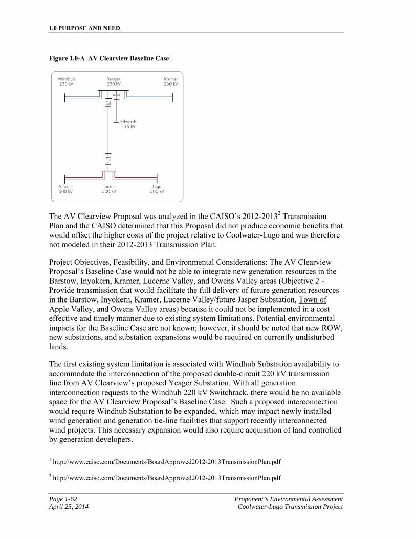
1.0 PURPOSE AND NEED
Page 1-62 Proponent’s Environmental Assessment April 25, 2014 Coolwater-Lugo Transmission Project
Figure 1.0-A AV Clearview Baseline Case1
The AV Clearview Proposal was analyzed in the CAISO’s 2012-20132 Transmission Plan and the CAISO determined that this Proposal did not produce economic benefits that would offset the higher costs of the project relative to Coolwater-Lugo and was therefore not modeled in their 2012-2013 Transmission Plan.
Project Objectives, Feasibility, and Environmental Considerations: The AV Clearview Proposal’s Baseline Case would not be able to integrate new generation resources in the Barstow, Inyokern, Kramer, Lucerne Valley, and Owens Valley areas (Objective 2 - Provide transmission that would facilitate the full delivery of future generation resources in the Barstow, Inyokern, Kramer, Lucerne Valley/future Jasper Substation, Town of Apple Valley, and Owens Valley areas) because it could not be implemented in a cost effective and timely manner due to existing system limitations. Potential environmental impacts for the Baseline Case are not known; however, it should be noted that new ROW, new substations, and substation expansions would be required on currently undisturbed lands.
The first existing system limitation is associated with Windhub Substation availability to accommodate the interconnection of the proposed double-circuit 220 kV transmission line from AV Clearview’s proposed Yeager Substation. With all generation interconnection requests to the Windhub 220 kV Switchrack, there would be no available space for the AV Clearview Proposal’s Baseline Case. Such a proposed interconnection would require Windhub Substation to be expanded, which may impact newly installed wind generation and generation tie-line facilities that support recently interconnected wind projects. This necessary expansion would also require acquisition of land controlled by generation developers.
1 http://www.caiso.com/Documents/BoardApproved2012-2013TransmissionPlan.pdf
2 http://www.caiso.com/Documents/BoardApproved2012-2013TransmissionPlan.pdf
1.0 PURPOSE AND NEED
Proponent’s Environmental Assessment Page 1-63 Coolwater-Lugo Transmission Project April 25, 2014
In addition, the connection of the two proposed transmission lines to Windhub Substation under the Baseline Case would result in significant short-circuit duty issues. Specifically, this alternative would exceed SCE’s maximum short-circuit duty design at Windhub Substation. To address the short-circuit duty limitation, significant and costly actions, such as the complete demolition of the existing 220 kV switchrack and the construction of new Gas Insulated Switchgear (“GIS”) 220 kV facilities with increased 80 kA short-circuit duty rating would be necessary. Upgrading Windhub Substation for short-circuit duty issues would require extremely long-term curtailment of recently interconnected generation resources. These curtailments could potentially cause significant monetary losses to the recently interconnected wind generation projects as well as result in a reduction to the overall renewable energy production while the upgrade is implemented, thereby adversely impacting RPS target goals (Objective 1 – Facilitate SCE and other California utilities achievement of California’s RPS) and creating costs in excess of $100 million of otherwise unnecessary work to convert Windhub’s existing 220 kV Switchrack to GIS (Objective 12 – meet project needs in a cost-effective and timely manner). Furthermore, the required curtailments of the Tehachapi area renewable generation connecting to and around Windhub Substation would require replacement generation which may not come from renewable resources, and which may not support California’s GHG Reduction Program (Objective 4 – Support California’s GHG Reduction Program).
Moreover, this proposal would not meet applicable CAISO, NERC and WECC planning criteria (Objective 3 – Comply with all applicable reliability planning criteria) as demonstrated by the CAISO’s analysis of the AV Clearview Proposal in their 2012-2013 Annual Transmission Plan1. The analysis indicated that the proposed connection from Yeager to SCE’s Edwards Substation would result in overloads on the proposed Yeager-Edwards 115 kV line, the existing Edwards-Holgate 115 kV line, and the existing Kramer-Holgate 115 kV line. The CAISO’s proposed mitigation for these overloads was to leave the proposed Yeager-Edwards 115 kV line open; however, this operating condition would result in this line having the sole purpose of providing energy redundancy for Edwards Air Force Base (“AFB”)2. SCE’s review of outage history has revealed that the existing 115 kV line serving Edwards AFB has not experienced a prolonged outage in the last ten years. All outages have been categorized as “open and reclose” operations and have thus been minimal in duration. Any proposed “energy redundancy” aspects would therefore not exist since the proposed line would be operated normally open and would close only upon loss of the existing 115 kV line. As such, the exact same outage duration would be experienced with or without AV Clearview’s proposed Yeager-Edwards 115 kV line. Consequently, the Yeager-Edwards 115 kV line provides no real measurable benefit and has not been identified to be required in any of the load serving studies that have been performed as part of the CAISO’s 2012-2013 Annual Transmission Plan. Furthermore, since the existing SCE Edwards Substation does not have a 115 kV switchrack, the proposed Yeager-Edwards 115 kV line would require a complete rebuild of Edwards Substation and the construction of an Edwards 115 kV 1 http://www.caiso.com/Documents/BoardApproved2012-2013TransmissionPlan.pdf
2 http://www.caiso.com/Documents/CriticalPathCommentsDraft2012-2013TransmissionPlan.pdf
1.0 PURPOSE AND NEED
Page 1-64 Proponent’s Environmental Assessment April 25, 2014 Coolwater-Lugo Transmission Project
Switchrack, which would also not meet Objective 12 (Objective 12 – meet project needs in a cost-effective and timely manner).
System Alternative 7 would also not facilitate the interconnection of CREST and Rule 21 projects (Objective 6 – Facilitate CREST, Re-MAT, and Rule 21 projects), address transmission capacity concerns from the City of Ridgecrest (Objective 8 – Address transmission capacity concerns from the City of Ridgecrest), or meet the project needs in a timely manner (Object 12 – Meet project needs in a timely manner) due to the lack of space on the Windhub 220 kV Switchrack to accommodate AV Clearview’s proposed connection from Yeager due to the short-circuit duty concerns from such a connection as described above and due to the need to rebuild SCE’s Edwards Substation. Objectives 6, 8, and 12 would not be achieved because System Alternative 7 would significantly delay the operating date due to the additional environmental review, agency approvals, and engineering that would be needed for construction of the AV Clearview Proposal, the required substation rebuilds that would be necessary at SCE’s Windhub and Edwards Substations, and any other necessary reliability upgrades in the SCE system that would be required as a result of the AV Clearview proposal.
This delay would negatively affect multiple large and small renewable generation requests currently in the CAISO and SCE generation interconnection queues, in addition to the 250275MW Barstow area renewable generation project, currently under construction, that are all seeking interconnection into SCE’s North of Kramer electrical area. By delaying the necessary transmission required for these project interconnections, System Alternative 7 would negatively affect the ability of these queued projects to negotiate PPAs due to delayed commercial operating dates, and would also negatively impact the resource adequacy status and PPA obligations of the 250275MW Barstow area renewable generation project. SCE is obligated to make a best effort with meeting the operating dates in generation interconnection agreements so that generation developer resource adequacy status or obligations under PPAs are not jeopardized. In addition, this extended delay for transmission capacity in the North of Kramer electrical area could lead to complaints filed with the CPUC against SCE for unfairly prohibiting renewable generation interconnection under the Feed-in Tariff program, and/or the CSI, or the NHSP.
Moreover, because the transmission facilities for Alternative 7 would be located on the west side of Highway 395, this alternative would not include a new Desert View Substation southeast of the town of Apple Valley (Objective 9 - License a new multipurpose substation to facilitate load serving, reliability, and future generation interconnections provide reliability, and support load growth and generation interconnections in the Apple Valley area). Alternative 7 would also not minimize environmental impacts or utilize the route that would minimize environmental impacts (Objective 11 – Minimize environmental impacts and utilize the shortest route that minimizes environmental impacts). The AV Clearview Proposal alternative would require approximately 84 miles of new transmission facilities on primarily new or
1.0 PURPOSE AND NEED
Proponent’s Environmental Assessment Page 1-65 Coolwater-Lugo Transmission Project April 25, 2014
expanded ROW, approximately 40 miles of which would be underground1. Underground transmission facilities usually involve a combination of trenching and tunneling and the installation of cooling equipment, splice vaults, and underground ducts. Undergrounding, as opposed to overhead construction, would result in more severe impacts to air quality from emission from construction equipment, could disturb cultural resources and potentially hazardous waste (e.g., mining waste) buried at shallow depths, and could also create noise and vibration, potentially affecting nearby structures , protected species, surface and groundwater resources and deeply buried geological and paleontological features. Additional land disturbance and environmental impact would also be required to rebuild Edwards 115 kV Substation, and to provide for Fiber-Optic telecommunication facilities. Because Alternative 7 would be located in a different area than the proposed Coolwater-Lugo, it may require substantially greater new telecommunication facilities to support line protection and possibly an SPS than Coolwater-Lugo. Alternative 7 could require approximately 128 miles of new Fiber-Optic cable between Lugo Substation and Vincent Substation requiring approximately 323 new poles2. The installation of these Fiber-Optic structures would require an undetermined amount of new roads, grading, and laydown areas. In addition, new microwave antennas may need to be installed at the proposed Tucker Substation and the existing Frost Peak communication site in Wrightwood, California.
In addition, Caltrans’ proposed SR-58 Kramer Junction Expressway Project3 would widen and realign a 13.3-mile segment of SR-58 centered on Kramer Junction, where SR-58 intersects with US-395, in San Bernardino County. The four possible build alternatives are located on the Caltrans SR-58 Kramer Junction Expressway Project website4. All of these four alternatives would negatively impact possible line routing to Kramer Substation under this system alternative. These complications would delay
1 While Critical Path Transmission, LLC, has stated in the CAISO 2012-2013 Annual Transmission Plan that the DC transmission line between Yeager and Tucker Substations will be built underground, they have not identified whether the transmission and subtransmission lines from Yeager Substation to Edwards, Windhub, and Kramer Substations will be overhead or underground and it is assumed these will be overhead. Based on information at criticalpathtransmission.com and from the AV Clearview map routes contained in the CAISO’s 2012-2013 Annual Transmission Plan, it is estimated that the AV Clearview Transmission Proposal will require approximately 40 miles of new underground transmission line between Yeager and Tucker Substations, approximately 42 miles of new transmission line connecting Windhub, Yeager and Kramer Substations, and two miles of new subtransmission line between Yeager and Edwards Substation. It is estimated that approximately only two miles of the 84 miles of the new substransmission and transmission required by the AV Clearview Transmission Proposal will be within an existing energy corridor.
2 As compared to the Kramer-Llano 500 kV upgrade as estimated in the CAISO Transition Cluster Phase II Interconnection Study Report for SCE’s East of Lugo Bulk System
3 http://dot.ca.gov/dist8/projects/san_bernardino/sr58/kramerjunction/index.htm
4 http://dot.ca.gov/dist8/projects/san_bernardino/sr58/kramerjunction/pdf/Alternative%20Project% 20Routes.pdf
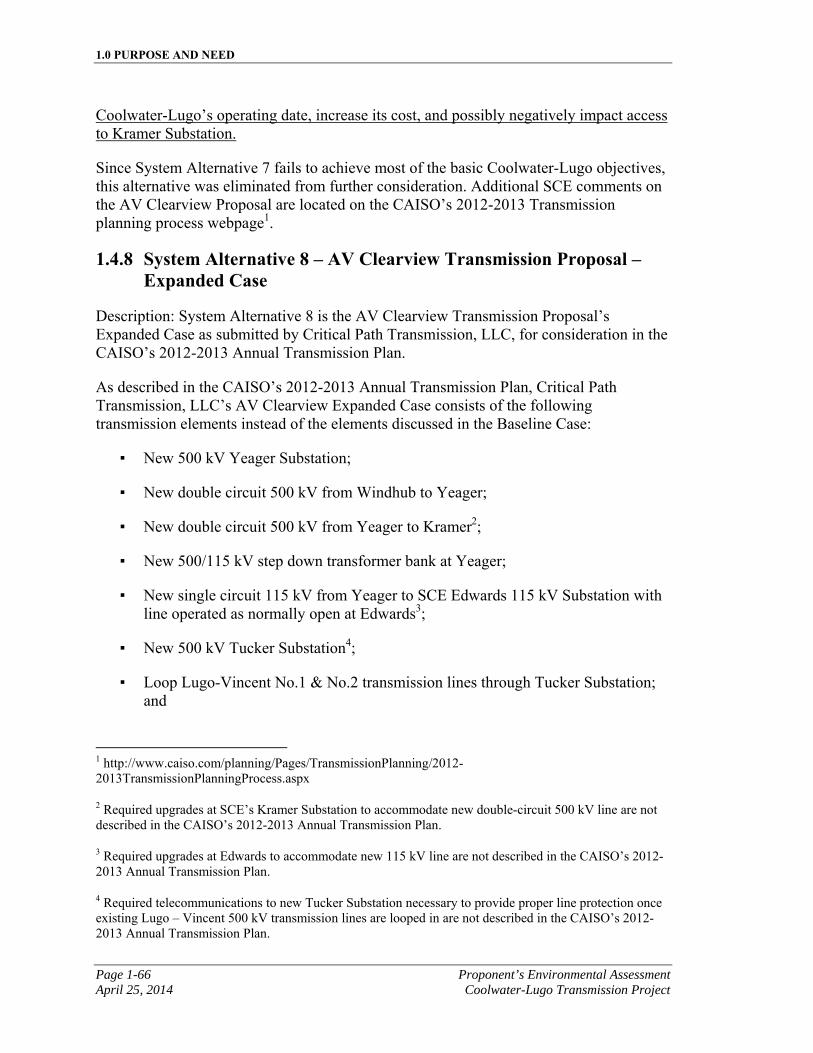
1.0 PURPOSE AND NEED
Page 1-66 Proponent’s Environmental Assessment April 25, 2014 Coolwater-Lugo Transmission Project
Coolwater-Lugo’s operating date, increase its cost, and possibly negatively impact access to Kramer Substation.
Since System Alternative 7 fails to achieve most of the basic Coolwater-Lugo objectives, this alternative was eliminated from further consideration. Additional SCE comments on the AV Clearview Proposal are located on the CAISO’s 2012-2013 Transmission planning process webpage1.
1.4.8 System Alternative 8 – AV Clearview Transmission Proposal – Expanded Case
Description: System Alternative 8 is the AV Clearview Transmission Proposal’s Expanded Case as submitted by Critical Path Transmission, LLC, for consideration in the CAISO’s 2012-2013 Annual Transmission Plan.
As described in the CAISO’s 2012-2013 Annual Transmission Plan, Critical Path Transmission, LLC’s AV Clearview Expanded Case consists of the following transmission elements instead of the elements discussed in the Baseline Case:
▪ New 500 kV Yeager Substation;
▪ New double circuit 500 kV from Windhub to Yeager;
▪ New double circuit 500 kV from Yeager to Kramer2;
▪ New 500/115 kV step down transformer bank at Yeager;
▪ New single circuit 115 kV from Yeager to SCE Edwards 115 kV Substation with line operated as normally open at Edwards3;
▪ New 500 kV Tucker Substation4;
▪ Loop Lugo-Vincent No.1 & No.2 transmission lines through Tucker Substation; and
1 http://www.caiso.com/planning/Pages/TransmissionPlanning/2012-2013TransmissionPlanningProcess.aspx
2 Required upgrades at SCE’s Kramer Substation to accommodate new double-circuit 500 kV line are not described in the CAISO’s 2012-2013 Annual Transmission Plan.
3 Required upgrades at Edwards to accommodate new 115 kV line are not described in the CAISO’s 2012-2013 Annual Transmission Plan.
4 Required telecommunications to new Tucker Substation necessary to provide proper line protection once existing Lugo – Vincent 500 kV transmission lines are looped in are not described in the CAISO’s 2012-2013 Annual Transmission Plan.
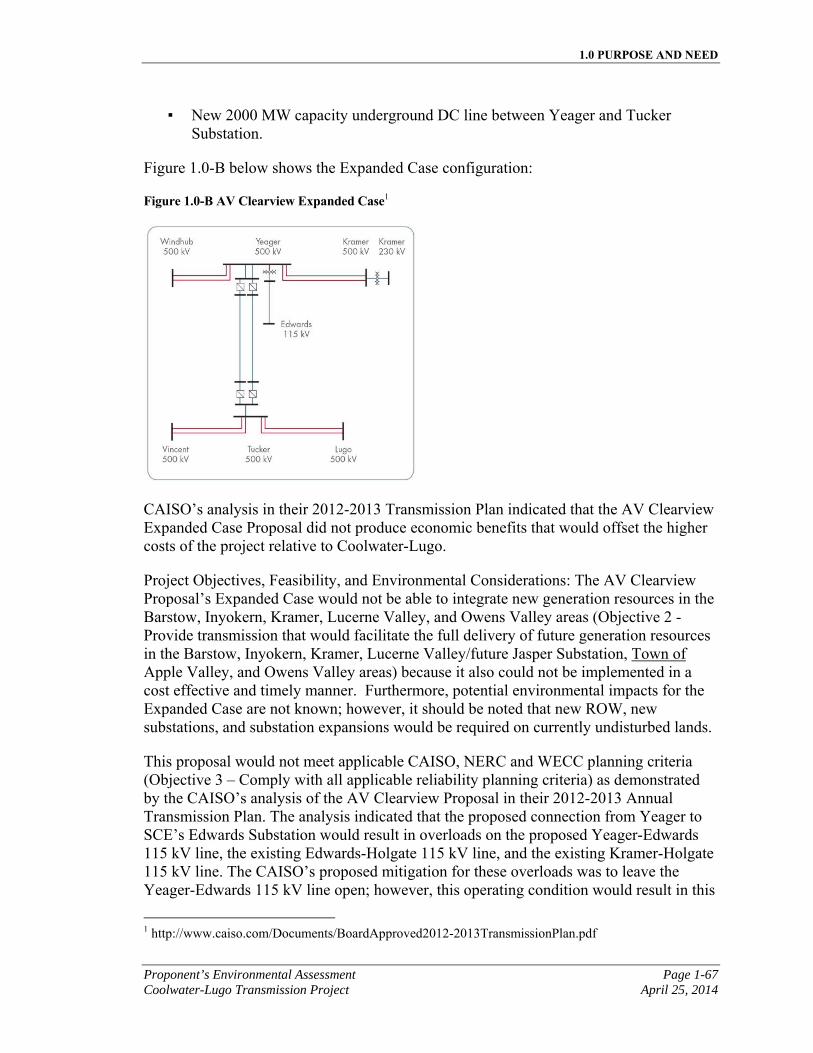
1.0 PURPOSE AND NEED
Proponent’s Environmental Assessment Page 1-67 Coolwater-Lugo Transmission Project April 25, 2014
▪ New 2000 MW capacity underground DC line between Yeager and Tucker Substation.
Figure 1.0-B below shows the Expanded Case configuration:
Figure 1.0-B AV Clearview Expanded Case1
CAISO’s analysis in their 2012-2013 Transmission Plan indicated that the AV Clearview Expanded Case Proposal did not produce economic benefits that would offset the higher costs of the project relative to Coolwater-Lugo.
Project Objectives, Feasibility, and Environmental Considerations: The AV Clearview Proposal’s Expanded Case would not be able to integrate new generation resources in the Barstow, Inyokern, Kramer, Lucerne Valley, and Owens Valley areas (Objective 2 - Provide transmission that would facilitate the full delivery of future generation resources in the Barstow, Inyokern, Kramer, Lucerne Valley/future Jasper Substation, Town of Apple Valley, and Owens Valley areas) because it also could not be implemented in a cost effective and timely manner. Furthermore, potential environmental impacts for the Expanded Case are not known; however, it should be noted that new ROW, new substations, and substation expansions would be required on currently undisturbed lands.
This proposal would not meet applicable CAISO, NERC and WECC planning criteria (Objective 3 – Comply with all applicable reliability planning criteria) as demonstrated by the CAISO’s analysis of the AV Clearview Proposal in their 2012-2013 Annual Transmission Plan. The analysis indicated that the proposed connection from Yeager to SCE’s Edwards Substation would result in overloads on the proposed Yeager-Edwards 115 kV line, the existing Edwards-Holgate 115 kV line, and the existing Kramer-Holgate 115 kV line. The CAISO’s proposed mitigation for these overloads was to leave the Yeager-Edwards 115 kV line open; however, this operating condition would result in this
1 http://www.caiso.com/Documents/BoardApproved2012-2013TransmissionPlan.pdf
1.0 PURPOSE AND NEED
Page 1-68 Proponent’s Environmental Assessment April 25, 2014 Coolwater-Lugo Transmission Project
line having the sole purpose of providing energy redundancy for Edwards AFB1. SCE’s review of outage history has revealed that the existing 115 kV line serving Edwards AFB has not experienced a prolonged outage in the last ten years. All outages have been categorized as “open and reclose” operations and have thus been minimal in duration. Any proposed “energy redundancy” aspects would therefore not exist since the proposed line would be operated normally open and would close only upon loss of the existing 115 kV line. As such, the exact same outage duration would be experienced with or without AV Clearview’s proposed Yeager-Edwards 115 kV line. Consequently, the Yeager-Edwards 115 kV line provides no real measurable benefit and has not been identified to be required in any of the load serving studies that have been performed as part of the CAISO’s Annual Transmission Plan. Furthermore, since the existing SCE Edwards Substation does not have a 115 kV switchrack, the proposed Yeager-Edwards 115 kV line would require a complete rebuild of Edwards Substation and the construction of an Edwards 115 kV Switchrack, which would also not meet Objective 12 (Objective 12 – meet project needs in a cost-effective and timely manner).
Furthermore, System Alternative 8 would not facilitate the interconnection of CREST and Rule 21 projects (Objective 6 – Facilitate CREST, Re-MAT, and Rule 21 projects), address transmission capacity concerns from the City of Ridgecrest (Objective 8 – Address transmission capacity concerns from the City of Ridgecrest), or meet the project needs in a timely manner (Object 12 – Meet project needs in a timely manner). Objectives 6, 8, and 12 would not be achieved because System Alternative 8 would significantly delay the operating date due to the additional environmental work, agency approvals, engineering that would be needed for construction of the AV Clearview Proposal’s Expanded Case, which includes but is not limited to the required substation rebuild of SCE’s Edwards Substation, the expansion of SCE’s existing Kramer 220/115 kV Substation to include 500 kV facilities, and new telecommunication facilities to support line protection and possibly an SPS.
Expansion of the existing Kramer Substation with 500 kV facilities would require approximately 92 additional acres adjacent to the existing Kramer Substation to accommodate the full build-out of a standard SCE designed 500/220 kV substation. Facilities to support a new double-circuit Yeager-Kramer 500 kV transmission line would require a 500 kV operating bus, one or more 500/220 kV transformer banks, a MEER, and the installation of additional ancillary equipment including but not limited to circuit breakers, disconnects, conductor, and system protection. In addition, this substation expansion would require the relocation of approximately two miles of the existing Kramer-Rocket Test 115 kV subtransmission line on expanded or new ROW.
This delay would negatively affect multiple large and small renewable generation requests currently in the CAISO and SCE generation interconnection queues, in addition to the 250275 MW Barstow area renewable generation project, currently under construction, that are all seeking interconnection into SCE’s North of Kramer electrical area. By delaying the necessary transmission required for these project interconnections, 1 http://www.caiso.com/Documents/CriticalPathCommentsDraft2012-2013TransmissionPlan.pdf
1.0 PURPOSE AND NEED
Proponent’s Environmental Assessment Page 1-69 Coolwater-Lugo Transmission Project April 25, 2014
System Alternative 8 would negatively affect the ability of these queued projects to negotiate PPAs due to delayed commercial operating dates and would also negatively impact the resource adequacy status and PPA obligations of the 250275 MW Barstow area renewable generation project. SCE is obligated to make a best effort with meeting the operating dates in generation interconnection agreements so that generation developer resource adequacy status or obligations under PPAs are not jeopardized. In addition, this extended delay for transmission capacity in the North of Kramer electrical area could lead to complaints filed with the CPUC against SCE for unfairly prohibiting renewable generation interconnection under the Feed-in Tariff program, and/or the CSI, or the NHSP.
Moreover, because transmission facilities for Alternative 8 would be located on the west side of Highway 395, this alternative would not include a new Desert View Substation southeast of the Town of Apple Valley (Objective 9 - License a new multipurpose substation to facilitate load serving, reliability, and future generation interconnections provide reliability, and support load growth and generation interconnections in the Apple Valley area). Alternative 8 would also not minimize environmental impacts or utilize the route that would minimize environmental impacts (Objective 11 – Minimize environmental impacts and utilize the shortest route that minimizes environmental impacts). AV Clearview’s Expanded Case would require approximately 84 miles of new transmission facilities on new or expanded ROW, approximately 40 miles of which would be underground1. Underground transmission facilities usually involve a combination of trenching and tunneling and the installation of cooling equipment, splice vaults, and underground ducts. Undergrounding would result in more severe impacts to air quality from emission from construction equipment, could disturb cultural resources and potentially hazardous waste (e.g., mining waste) buried at shallow depths, and could also create noise and vibration, potentially affecting nearby structures , protected species, surface and groundwater resources and deeply buried geological and paleontological features. Furthermore, an additional 92 acres would be required to expand SCE’s existing Kramer Substation to include 500 kV facilities, a two mile subtransmission line would require relocation, SCE’s Edwards 115 kV Substation would need to be rebuilt to include a 115 kV switchrack, and Fiber-Optic telecommunication facilities. Because Alternative 8 would be located in a different area than the proposed Coolwater-Lugo, it may require substantially greater new telecommunication facilities to support line protection and possibly an SPS than Coolwater-Lugo. Alternative 8 could require approximately 128 miles of new Fiber-Optic cable between Lugo Substation and Vincent Substation requiring approximately 323 new poles2. The installation of these Fiber-Optic structures would require an undetermined amount of new roads, grading, and laydown areas. In addition, new microwave antennas may need to be installed at the proposed Tucker Substation and the existing Frost Peak communication site in Wrightwood, California.
1 See Footnote 25.
2 As compared to the Kramer-Llano 500 kV upgrade as estimated in the CAISO Transition Cluster Phase II Interconnection Study Report for SCE’s East of Lugo Bulk System
1.0 PURPOSE AND NEED
Page 1-70 Proponent’s Environmental Assessment April 25, 2014 Coolwater-Lugo Transmission Project
Alternative 8 would also not meet the cost goals of Objective 12 (Objective 12 - Meet project needs in a cost-effective manner). SCE has identified additional significant costs that would be necessary for the AV Clearview’s Expanded Case Proposal, which were not identified in the CAISO’s 2012-2013 Transmission Plan1. These costs include the expansion of SCE’s existing Kramer Substation to include 500 kV facilities, the rebuild of SCE’s existing Edwards Substation to include a 115 kV Switchrack, and the 128 miles of telecommunications, all of which would not be required as part of Coolwater-Lugo, and which would result in higher costs passed on to SCE ratepayers. Finally, the AV Clearview Proposal’s Expanded Case was determined not to be needed by the CAISO and was therefore not modeled in their 2012-2013 Transmission Plan.
In addition, future expansion of Kramer Substation with 500 kV facilities may not be possible due to Caltrans’ proposed SR-58 Kramer Junction Expressway Project.2 This proposed Caltrans Project would widen and realign a 13.3-mile segment of SR-58 centered on Kramer Junction, where SR-58 intersects with US-395, in San Bernardino County. The four possible build alternatives are located on the Caltrans SR-58 Kramer Junction Expressway Project website3. All of these four alternatives would negatively impact the expansion of Kramer Substation to 500 kV and/or possible line routing to Kramer Substation. These complications would delay Coolwater-Lugo’s operating date, increase its cost, and possibly negatively impact access to Kramer Substation.
Since System Alternative 8 fails to achieve most of the basic Coolwater-Lugo objectives, this alternative was eliminated from further consideration. Additional SCE comments on the AV Clearview Proposal are located on the CAISO’s 2012-2013 Transmission planning process webpage4.
1.4.9 System Alternative 9 - No Project Alternative
Description: Under the No Project Alternative, there would be no facility upgrades or other changes to the electric transmission system. Proposed alternatives, including new and upgraded transmission lines and substations, would not be constructed.
Project Objectives, Feasibility, and Environmental Considerations: With implementation of the No Project Alternative, the following key objectives would not be met:
1 SCE believes the costs of the AV Clearview’s Baseline and Expanded Case Proposals are underestimated because both these proposal require SCE upgrades to existing facilities and SCE was never contacted for the necessary cost and scope estimates.
2 http://dot.ca.gov/dist8/projects/san_bernardino/sr58/kramerjunction/index.htm
3 http://dot.ca.gov/dist8/projects/san_bernardino/sr58/kramerjunction/pdf/Alternative%20Project% 20Routes.pdf
4 http://www.caiso.com/planning/Pages/TransmissionPlanning/2012-2013TransmissionPlanningProcess.aspx
1.0 PURPOSE AND NEED
Proponent’s Environmental Assessment Page 1-71 Coolwater-Lugo Transmission Project April 25, 2014
1. Facilitate SCE and other California utilities achievement of California’s RPS in an expedited manner;
2. Provide transmission facilities identified as necessary for the full delivery of 1) a 250275 MW renewable generation project located in the Barstow area; 2) future generation resources in the Barstow, Inyokern, Kramer, Lucerne Valley, Town of Apple Valley, and Owens Valley areas;
3. Support California’s GHG Reduction Program;
4. Support BLM compliance with the Federal Renewable Energy Mandate;
5. Provide transmission facilities in a timely manner that would facilitate the interconnection of CREST and Rule 21 projects;
6. Provide transmission facilities that facilitate the Department of Defense meeting their Energy Mandate of producing or procuring 25% of their total energy from renewable energy sources beginning in 2025 as outlined under the National Defense Authorization Act of 2010;1
7. Address transmission capacity concerns from the City of Ridgecrest;
8. License a new multipurpose 500/220/115/12 kV Desert View Substation southeast of the Town of Apple Valley to facilitate load serving, reliability, and future generation interconnections; and,
9. Meet project needs in a cost-effective and timely manner.
The No Project Alternative would not meet the project objectives, but is retained in the PEA to enable the CPUC to compare the impacts of approving the proposed Coolwater-Lugo with the impacts of not approving the project.
1.5 System Alternatives Comparison
SCE evaluated each system alternative for its ability to meet the project objectives. Each of these alternatives differs according to environmental impacts, engineering feasibility, and cost. SCE concluded that Coolwater-Lugo (the system alternative presented in Section 1.0) is the only feasible alternative that could be implemented in an efficient and expedited manner that would meet all 13 project objectives presented in Section 1.3 However, as discussed in Section 1.4, Electric System Alternatives, the analysis determined that the following system alternatives are feasible, but do not meet all 13 of the basic project objectives:
▪ System Alternative 1 – Coolwater-Pisgah 220 kV Transmission Line
1 See http://www.govenergy.com/2010/Files/Presentations/Renewables/2010_GovEnergy_Tindal.pdf
1.0 PURPOSE AND NEED
Page 1-72 Proponent’s Environmental Assessment April 25, 2014 Coolwater-Lugo Transmission Project
▪ System Alternative 4 – Kramer-Lugo No.3 220 kV Transmission Line
▪ System Alternative 5 – Kramer-Llano 500 kV Transmission Line
▪ System Alternative 6 – Kramer-Llano 500 kV Transmission Line and Rebuild of Lugo-Pisgah No.1 220 kV Transmission Line
▪ System Alternative 7 – AV Clearview Transmission Proposal – Baseline Case
▪ System Alternative 8 – AV Clearview Transmission Proposal – Expanded Case
▪ System Alternative 9 – No Project Alternative
1.5.1 System Alternatives Considered and Eliminated
As described in section 1.4, the following system alternatives were considered and eliminated because they failed to meet most of the basic project objectives:
▪ System Alternative 1 – Coolwater-Pisgah 220 kV Transmission Line
▪ System Alternative 2 – Rebuilding the Kramer-Lugo 220 kV Transmission Lines
▪ System Alternative 3 – Reconductoring the Kramer-Lugo 220 kV Transmission Lines
▪ System Alternative 4 – Kramer-Lugo No.3 220 kV Transmission Line
▪ System Alternative 5 – Kramer-Llano 500 kV Transmission Line
▪ System Alternative 6 – Kramer-Llano 500 kV Transmission Line and Rebuild of Lugo-Pisgah No.1 220 kV Transmission Line
▪ System Alternative 7 – AV Clearview Transmission Proposal – Baseline Case
▪ System Alternative 8 – AV Clearview Transmission Proposal – Expanded Case
▪ System Alternative 9 – No Project Alternative
1.6 Project Summary
To provide additional south of Kramer capacity to integrate current and future renewable generation projects, SCE needs to develop new and upgraded transmission facilities. These new and upgraded transmission facilities would eliminate the bottlenecks that would preclude renewable generation resources from reaching the utility load centers. To this end, SCE is required to develop and maintain a reliable transmission network with adequate capacity. The facilities needed to deliver the electrical power from the new planned generation resources located in the Barstow, Inyokern, Kramer, Lucerne Valley, and Owens Valley areas have been identified through generation interconnection studies
1.0 PURPOSE AND NEED
Proponent’s Environmental Assessment Page 1-73 Coolwater-Lugo Transmission Project April 25, 2014
performed as mandated by the CAISO. The major components of these facilities are summarized below with complete descriptions provided in Chapter 3, Project Description.
1.6.1 Substations
▪ Reconfigure Coolwater 220 kV Switchyard
▪ Terminate new Coolwater-Desert View 220 kV Transmission Line at the Coolwater and Desert View 220 kV buses
▪ Install new relay buildings and necessary equipment to support the SPS at Coolwater 220 kV Switchyard
▪ Expand the Lugo 500 kV Switchrack to the south five positions
▪ Relocate two existing 500 kV transmission line terminations at Lugo Substation
▪ Terminate new Desert View-Lugo 220 kV Transmission Line at the Desert View and Lugo 220 kV buses
▪ Install one 500/220 kV transformer bank at Lugo Substation
▪ Construct new relay building and install bank protection relays at Lugo Substation
▪ Install new protection, control, and SPS at Lugo Substation
▪ License proposed Desert View 500/220/115/12 kV Substation and initially construct the facilities necessary to loop Coolwater-Lugo 220 kV Transmission Line and the Lugo-Pisgah No.1 & No.2 220 kV Transmission Lines into Desert View Substation including new protection, control, and SPS at Desert View Substation.
1.6.2 Transmission and Telecommunication
▪ Remove approximately 29.1 miles of the existing Lugo-Pisgah No.1 220 kV Transmission Line from Lugo Substation northeast to approximately the intersection of Haynes Road and SR-247
▪ Remove approximately 16.0 miles of the existing Lugo-Pisgah No.2 220 kV Transmission Line from Lugo Substation northeast to proposed Desert View Substation and terminate the remaining portion of this line into the proposed Desert View Substation
▪ Construct 16.6 miles of 500 kV single-circuit transmission line utilizing 2B-2156 ASCR conductor (initially operated at 220 kV) from Lugo Substation to the proposed Desert View Substation and 13.6 miles of 220 kV double-circuit
1.0 PURPOSE AND NEED
Page 1-74 Proponent’s Environmental Assessment April 25, 2014 Coolwater-Lugo Transmission Project
transmission line in existing ROW from proposed Desert View Substation to approximately the intersection of Haynes Road and SR-247
▪ Construct approximately 34.0 miles of 220 kV double-circuit transmission line from Coolwater 220 kV Switchyard south to the existing Lugo-Pisgah transmission corridor, located approximately near the intersection of Haynes Road and SR-247
▪ Install a new 150-foot tall microwave tower and foundation at the existing Coolwater 220 kV Switchyard
▪ Install lightwave transponder equipment or optical amplifier and channel bank equipment at Coolwater Switchyard, Lugo Substation, and the proposed Desert View Substation
▪ Install approximately 11.0 miles of Fiber-Optic Cable from existing Apple Valley Substation to the proposed Desert View Substation
▪ Install approximately 29.0 miles of Fiber-Optic Cable from existing Pisgah Substation near Ludlow to the existing Gale Substation near Daggett
3.0 PROJECT DESCRIPTION
Page 3-1 Proponent’s Environmental Assessment April 25, 2014 Coolwater-Lugo Transmission Project
3.0 PROJECT DESCRIPTION
This section provides a detailed description of Southern California Edison Company’s (“SCE”) Coolwater-Lugo Transmission Project. The following chapter describes the elements associated with the Proposed Project, followed by a discussion of the elements unique to the Alternative Project.
The Proposed Project includes the following elements:
▪ Construction of a new 500/220/115/12 kilovolt (“kV”) substation (“Proposed Desert View Substation”) west of Lucerne Valley and southeast of the Town of Apple Valley. The substation would be an unstaffed, automated substation, initially functioning as a switching station, with a potential capacity of 4,000 MVA at full build out. Under the minimum build out scenario option, 13.5 acres would be graded and a four position 220 kV switchrack and associated equipment surrounded by a chain link fence would be installed. Under the initial build out scenario, 86 acres would be graded and a four position 220 kV switchrack and associated equipment surrounded by a wall would be installed;
▪ Installation of a 220 kV transmission line approximately 34.0 miles long, and of double-circuit construction in new right-of way (“ROW”) located between the existing Coolwater Generating Station 220 kV Switchyard (“Coolwater Switchyard”) and the location of the future Jasper Substation1, southwest of the intersection of Haynes Road and State Route 247 (“SR-247”). Under the minimum build out scenario option, one side of the double-circuit structures are strung whereas under initial and full build out senarios, both sides of the double-circuit structures are strung;
▪ Installation of a 220 kV transmission line approximately 13.6 miles long, and of double-circuit construction in existing SCE transmission ROW, located from southwest of the intersection of Haynes Road and SR-247 to the Proposed Desert View Substation;
▪ Installation of a single-circuit 500 kV transmission line utilizing 2B-2156 ACSR2, initially energized at 220 kV, approximately 16.6 miles long, and of single-circuit construction in existing ROW, from the Proposed Desert View Substation to the existing Lugo Substation;
▪ Installation of a temporary transmission line (“shoo-fly”) approximately 4.3 miles long needed for construction of the Proposed 500 kV Transmission Line segment.
1 The future Jasper Substation would be triggered by a generation interconnection project and would be processed under a separate Permit to Construct.
2 2B-2156 ACSR conductor as specified by the Mojave Solar Project’s LGIA located at: http://elibrary.ferc.gov/idmws/common/opennat.asp?fileID=13376929
3.0 PROJECT DESCRIPTION
Proponent’s Environmental Assessment Page 3-2 Coolwater-Lugo Transmission Project April 25, 2014
The shoo-fly would be located in existing SCE ROW west of the Mojave River between the Proposed Desert View Substation and existing Lugo Substation;
▪ Removal of approximately 29.1 miles of the existing Lugo-Pisgah No.1 220 kV transmission line between existing Lugo Substation and a location southwest of the intersection of Haynes Road and SR-247;
▪ Removal of approximately 16.0 miles of the existing Lugo-Pisgah No. 2 220 kV transmission line between existing Lugo Substation and Proposed Desert View Substation;
▪ Termination of the remaining portions of the existing Lugo-Pisgah No. 1 and No. 2 220 kV lines into the Proposed Desert View Substation;
▪ Relocation of existing subtransmission lines, distribution, and telecommunication facilities, as needed, to accommodate construction of the Proposed Project, meet CPUC General Order (“G.O.”) 95 clearance standards, and facilitate safer construction and operation of the existing, as well as new electrical utility infrastructure;
▪ Installation of distribution facilities from the south side of Desert View Road to the Proposed Desert View Substation site to provide station light and power;
▪ Installation of telecommunication facilities to connect the Proposed Project to SCE’s existing telecommunication system to include Optical Groundwire (“OPGW”) on the Proposed Transmission Line Route; installation of new All Dielectric Self-Supporting (“ADSS”) fiber-optic cable on existing and new wood and light weight steel (“LWS”) poles between existing Apple Valley Substation and Proposed Desert View Substation, and on existing wood and LWS poles between existing Gale Substation and Pisgah Substation; and, a new microwave tower, antenna dish and equipment at Coolwater Switchyard; and,
▪ Other major components associated with the Proposed Project include modifications and new equipment installation at existing SCE substations, and removal and relocation of underground utilities.
The project description is based on planning level assumptions. Exact details would be determined following completion of final engineering, identification of field conditions, availability of labor, material, and equipment, and compliance with applicable environmental and permitting requirements.
3.0 PROJECT DESCRIPTION
Page 3-3 Proponent’s Environmental Assessment April 25, 2014 Coolwater-Lugo Transmission Project
3.1 Proposed Project Components
The components of the Proposed Project are described in more detail below:
3.1.1 Substation Description
The Proposed Desert View Substation (also referred to as “Proposed Substation”) includes three two construction scenarios, referred to as minimum build out, initial build out and full build out. Minimum build out or iInitial build out are is anticipated to commence in 2016 in conjunction with construction and installation of other project components including transmission, telecommunication, and distribution. The minimum build out includes just the components necessary to achieve the project purpose and objectives (as defined in Chapter 1). For purposes of the environmental analysis, the following description of the substation components associated with The initial build out is the proposed project and includes are based on the maximum initial build out all facilities necessary to achieve the project purpose and objectives (as defined in Chapter 1) as well as those facilities appropriate for future growth. connect and operate the Coolwater-Lugo transmission line and associated telecommunication facilities, assuming use of the Proposed Transmission Line Route. Initial build out requirements would depend on system requirements at the time of initial construction and the transmission line route selected, which could decrease the amount of initial build out facilities required. Full build out is anticipated to commence in the future, dependent upon the timing of area load growth, reliability needs and generation interconnection requests. Components proposed to occur during the full build out scenario could occur over time; however, for purposes of analyzing impacts associated with the full build out of Proposed Desert View Substation, SCE has assumed a worst case impact scenario where all of Proposed Desert View Substation is built out at one time.
Project components anticipated to occur during minimum build out, initial build out and full build out scenarios are presented in Table 3.1-A, Substation Component Summary at Minimum, Initial and Full Build Out Scenarios, below followed by a description of each component and the associated work for the minimum, initial and full build out scenarios.
3.0 PROJECT DESCRIPTION
Proponent’s Environmental Assessment Page 3-4 Coolwater-Lugo Transmission Project April 25, 2014
This page is intentionally blank
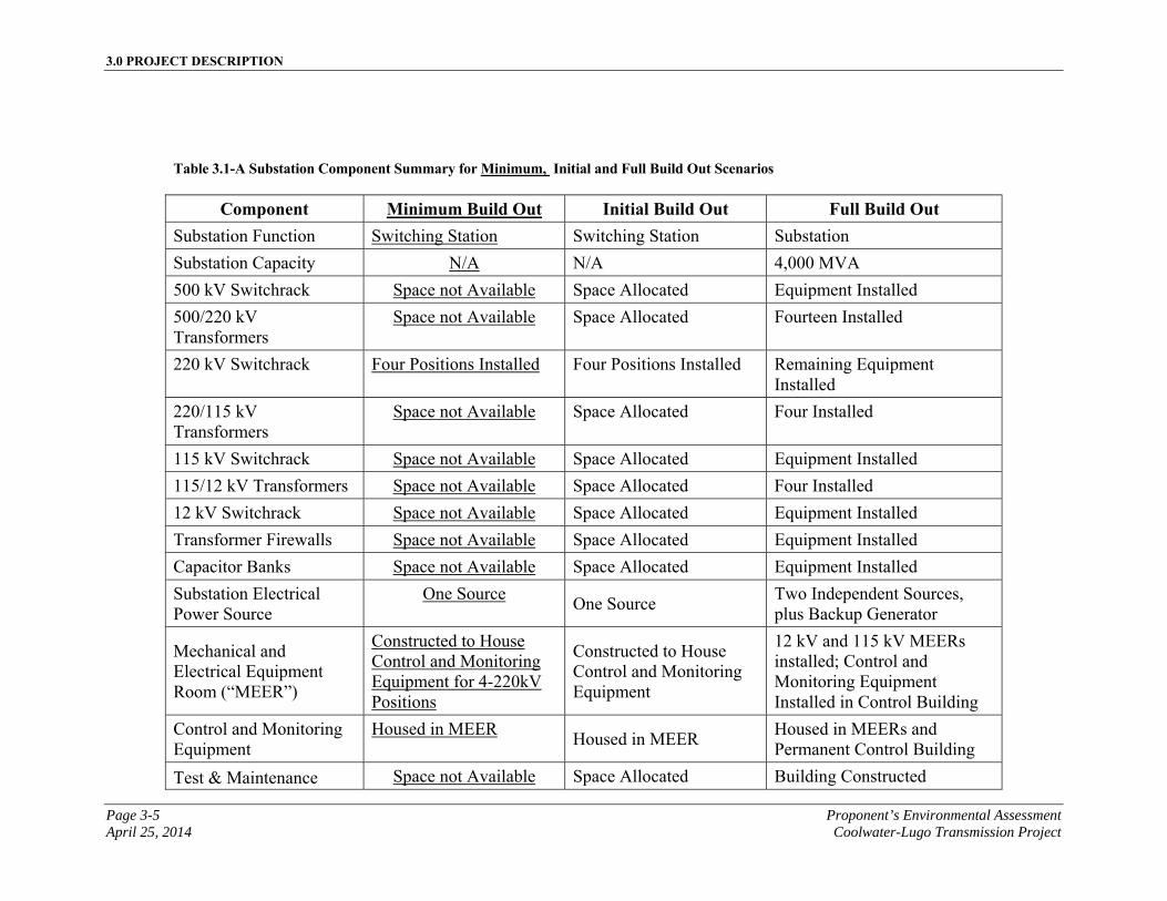
3.0 PROJECT DESCRIPTION
Page 3-5 Proponent’s Environmental Assessment April 25, 2014 Coolwater-Lugo Transmission Project
Table 3.1-A Substation Component Summary for Minimum, Initial and Full Build Out Scenarios
Component Minimum Build Out Initial Build Out Full Build Out Substation Function Switching Station Switching Station Substation
Substation Capacity N/A N/A 4,000 MVA
500 kV Switchrack Space not Available Space Allocated Equipment Installed
500/220 kV Transformers
Space not Available Space Allocated Fourteen Installed
220 kV Switchrack Four Positions Installed Four Positions Installed Remaining Equipment Installed
220/115 kV Transformers
Space not Available Space Allocated Four Installed
115 kV Switchrack Space not Available Space Allocated Equipment Installed
115/12 kV Transformers Space not Available Space Allocated Four Installed
12 kV Switchrack Space not Available Space Allocated Equipment Installed
Transformer Firewalls Space not Available Space Allocated Equipment Installed
Capacitor Banks Space not Available Space Allocated Equipment Installed
Substation Electrical Power Source
One Source One Source
Two Independent Sources, plus Backup Generator
Mechanical and Electrical Equipment Room (“MEER”)
Constructed to House Control and Monitoring Equipment for 4-220kV Positions
Constructed to House Control and Monitoring Equipment
12 kV and 115 kV MEERs installed; Control and Monitoring Equipment Installed in Control Building
Control and Monitoring Equipment
Housed in MEER Housed in MEER
Housed in MEERs and Permanent Control Building
Test & Maintenance Space not Available Space Allocated Building Constructed
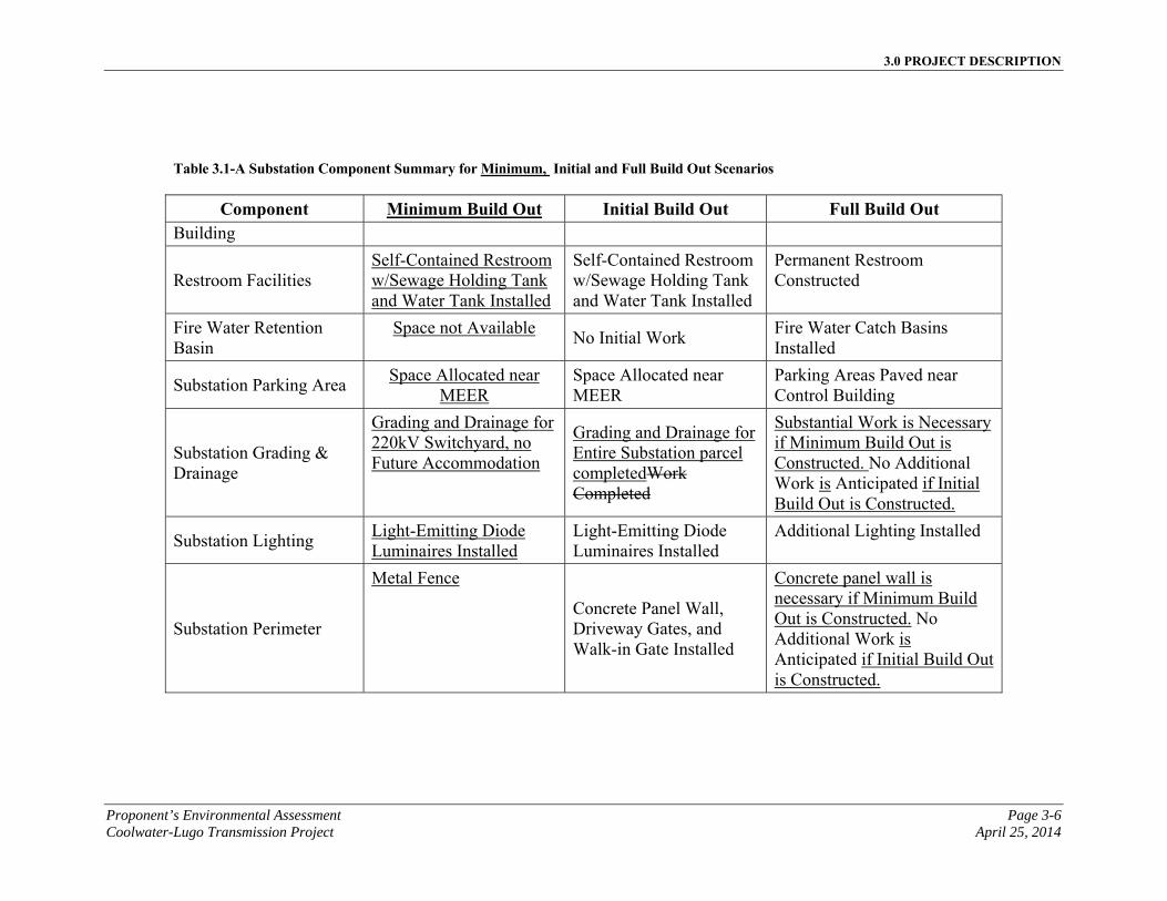
3.0 PROJECT DESCRIPTION
Proponent’s Environmental Assessment Page 3-6 Coolwater-Lugo Transmission Project April 25, 2014
Table 3.1-A Substation Component Summary for Minimum, Initial and Full Build Out Scenarios
Component Minimum Build Out Initial Build Out Full Build Out Building
Restroom Facilities Self-Contained Restroom w/Sewage Holding Tank and Water Tank Installed
Self-Contained Restroom w/Sewage Holding Tank and Water Tank Installed
Permanent Restroom Constructed
Fire Water Retention Basin
Space not Available No Initial Work
Fire Water Catch Basins Installed
Substation Parking Area Space Allocated near
MEER Space Allocated near MEER
Parking Areas Paved near Control Building
Substation Grading & Drainage
Grading and Drainage for 220kV Switchyard, no Future Accommodation
Grading and Drainage for Entire Substation parcel completedWork Completed
Substantial Work is Necessary if Minimum Build Out is Constructed. No Additional Work is Anticipated if Initial Build Out is Constructed.
Substation Lighting Light-Emitting Diode Luminaires Installed
Light-Emitting Diode Luminaires Installed
Additional Lighting Installed
Substation Perimeter
Metal Fence Concrete Panel Wall,
Driveway Gates, and Walk-in Gate Installed
Concrete panel wall is necessary if Minimum Build Out is Constructed. No Additional Work is Anticipated if Initial Build Out is Constructed.
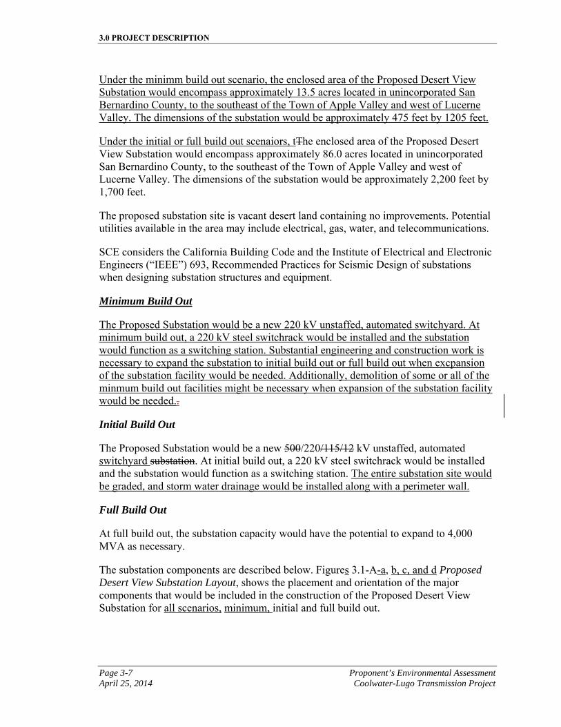
3.0 PROJECT DESCRIPTION
Page 3-7 Proponent’s Environmental Assessment April 25, 2014 Coolwater-Lugo Transmission Project
Under the minimm build out scenario, the enclosed area of the Proposed Desert View Substation would encompass approximately 13.5 acres located in unincorporated San Bernardino County, to the southeast of the Town of Apple Valley and west of Lucerne Valley. The dimensions of the substation would be approximately 475 feet by 1205 feet.
Under the initial or full build out scenaiors, tThe enclosed area of the Proposed Desert View Substation would encompass approximately 86.0 acres located in unincorporated San Bernardino County, to the southeast of the Town of Apple Valley and west of Lucerne Valley. The dimensions of the substation would be approximately 2,200 feet by 1,700 feet.
The proposed substation site is vacant desert land containing no improvements. Potential utilities available in the area may include electrical, gas, water, and telecommunications.
SCE considers the California Building Code and the Institute of Electrical and Electronic Engineers (“IEEE”) 693, Recommended Practices for Seismic Design of substations when designing substation structures and equipment.
Minimum Build Out
The Proposed Substation would be a new 220 kV unstaffed, automated switchyard. At minimum build out, a 220 kV steel switchrack would be installed and the substation would function as a switching station. Substantial engineering and construction work is necessary to expand the substation to initial build out or full build out when excpansion of the substation facility would be needed. Additionally, demolition of some or all of the minmum build out facilities might be necessary when expansion of the substation facility would be needed..
Initial Build Out
The Proposed Substation would be a new 500/220/115/12 kV unstaffed, automated switchyard substation. At initial build out, a 220 kV steel switchrack would be installed and the substation would function as a switching station. The entire substation site would be graded, and storm water drainage would be installed along with a perimeter wall.
Full Build Out
At full build out, the substation capacity would have the potential to expand to 4,000 MVA as necessary.
The substation components are described below. Figures 3.1-A-a, b, c, and d Proposed Desert View Substation Layout, shows the placement and orientation of the major components that would be included in the construction of the Proposed Desert View Substation for all scenarios, minimum, initial and full build out.

3.0 PROJECT DESCRIPTION
Proponent’s Environmental Assessment Page 3-8 Coolwater-Lugo Transmission Project April 25, 2014
This page is intentionally blank
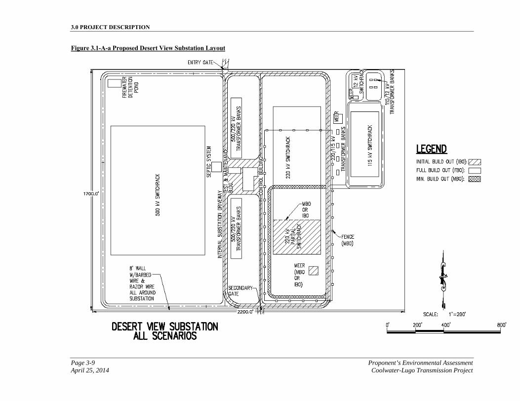
3.0 PROJECT DESCRIPTION
Page 3-9 Proponent’s Environmental Assessment April 25, 2014 Coolwater-Lugo Transmission Project
This page is intentionally blank.
Figure 3.1-A-a Proposed Desert View Substation Layout
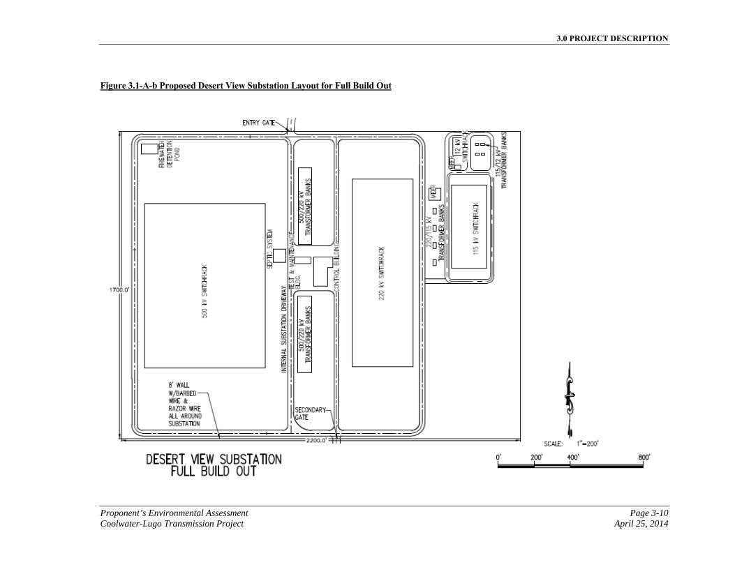
3.0 PROJECT DESCRIPTION
Proponent’s Environmental Assessment Page 3-10 Coolwater-Lugo Transmission Project April 25, 2014
Figure 3.1-A-b Proposed Desert View Substation Layout for Full Build Out
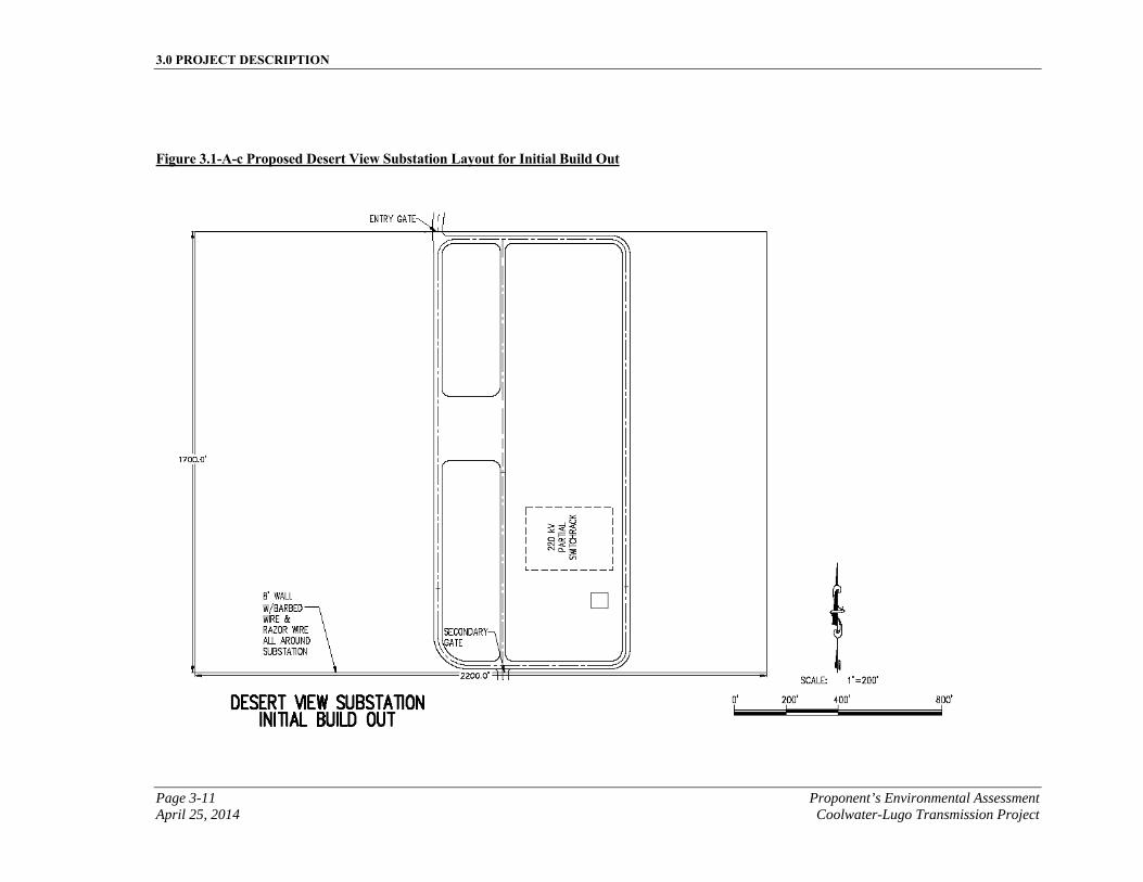
3.0 PROJECT DESCRIPTION
Page 3-11 Proponent’s Environmental Assessment April 25, 2014 Coolwater-Lugo Transmission Project
Figure 3.1-A-c Proposed Desert View Substation Layout for Initial Build Out
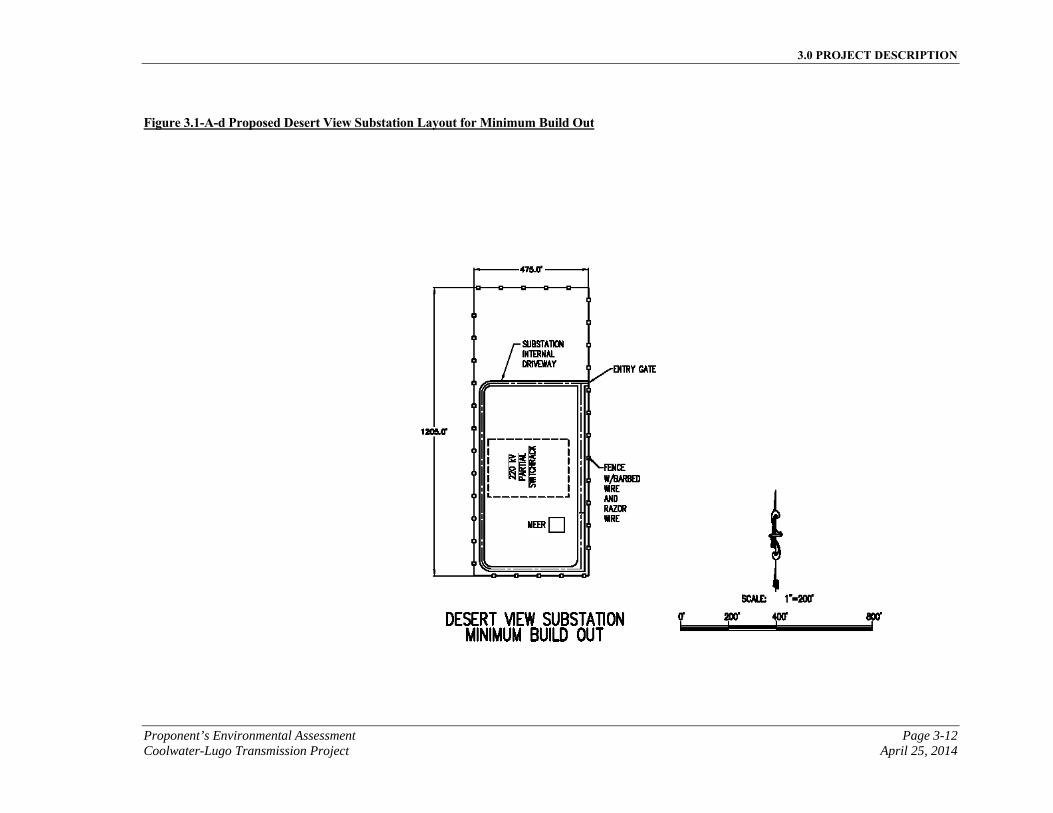
3.0 PROJECT DESCRIPTION
Proponent’s Environmental Assessment Page 3-12 Coolwater-Lugo Transmission Project April 25, 2014
Figure 3.1-A-d Proposed Desert View Substation Layout for Minimum Build Out
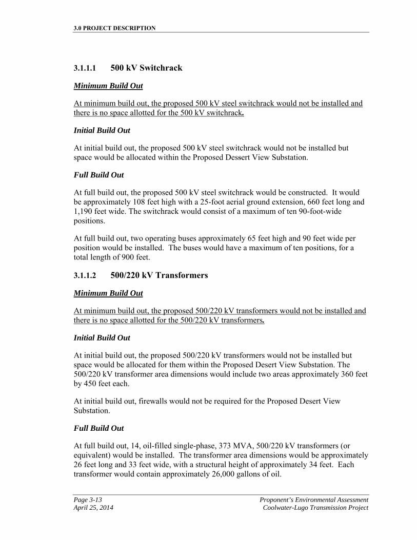
3.0 PROJECT DESCRIPTION
Page 3-13 Proponent’s Environmental Assessment April 25, 2014 Coolwater-Lugo Transmission Project
3.1.1.1 500 kV Switchrack
Minimum Build Out
At minimum build out, the proposed 500 kV steel switchrack would not be installed and there is no space allotted for the 500 kV switchrack.
Initial Build Out
At initial build out, the proposed 500 kV steel switchrack would not be installed but space would be allocated within the Proposed Dessert View Substation.
Full Build Out
At full build out, the proposed 500 kV steel switchrack would be constructed. It would be approximately 108 feet high with a 25-foot aerial ground extension, 660 feet long and 1,190 feet wide. The switchrack would consist of a maximum of ten 90-foot-wide positions.
At full build out, two operating buses approximately 65 feet high and 90 feet wide per position would be installed. The buses would have a maximum of ten positions, for a total length of 900 feet.
3.1.1.2 500/220 kV Transformers
Minimum Build Out
At minimum build out, the proposed 500/220 kV transformers would not be installed and there is no space allotted for the 500/220 kV transformers.
Initial Build Out
At initial build out, the proposed 500/220 kV transformers would not be installed but space would be allocated for them within the Proposed Desert View Substation. The 500/220 kV transformer area dimensions would include two areas approximately 360 feet by 450 feet each.
At initial build out, firewalls would not be required for the Proposed Desert View Substation.
Full Build Out
At full build out, 14, oil-filled single-phase, 373 MVA, 500/220 kV transformers (or equivalent) would be installed. The transformer area dimensions would be approximately 26 feet long and 33 feet wide, with a structural height of approximately 34 feet. Each transformer would contain approximately 26,000 gallons of oil.
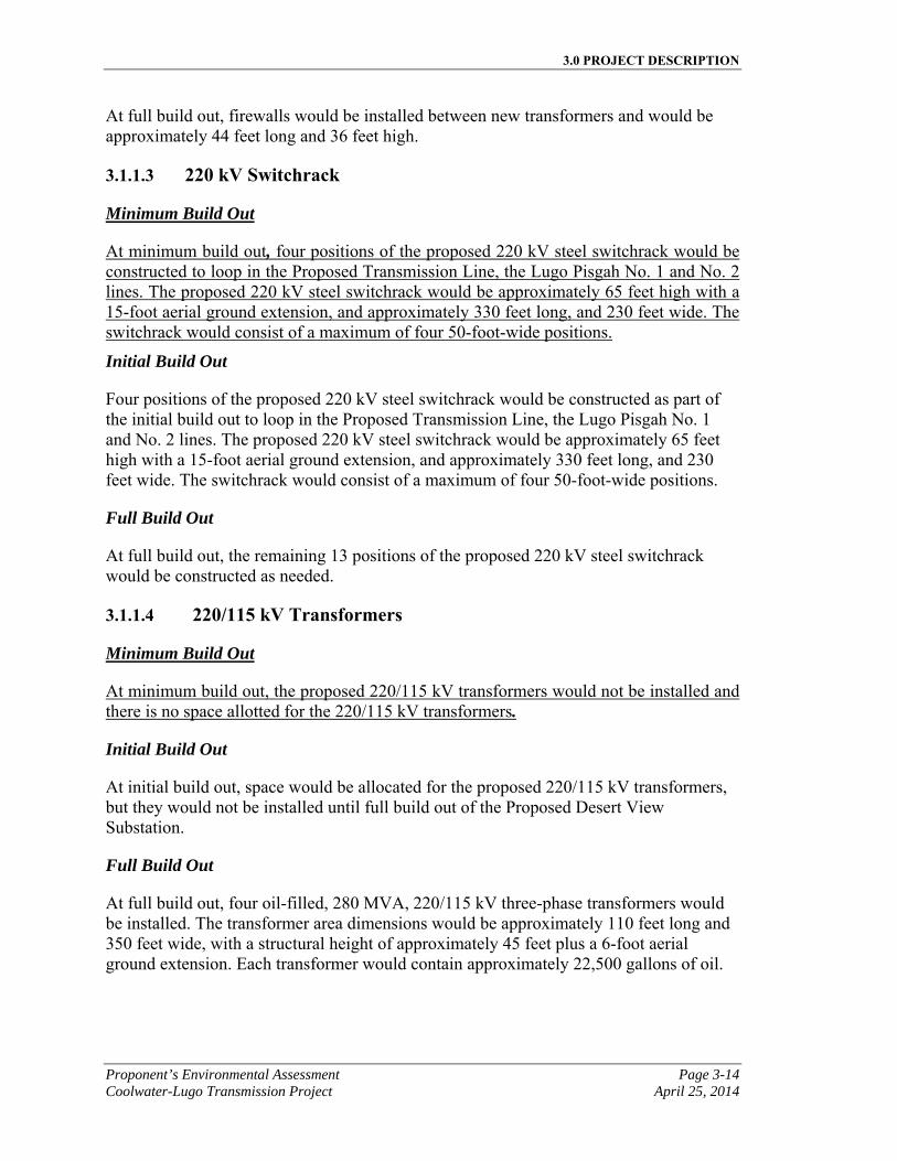
3.0 PROJECT DESCRIPTION
Proponent’s Environmental Assessment Page 3-14 Coolwater-Lugo Transmission Project April 25, 2014
At full build out, firewalls would be installed between new transformers and would be approximately 44 feet long and 36 feet high.
3.1.1.3 220 kV Switchrack
Minimum Build Out
At minimum build out, four positions of the proposed 220 kV steel switchrack would be constructed to loop in the Proposed Transmission Line, the Lugo Pisgah No. 1 and No. 2 lines. The proposed 220 kV steel switchrack would be approximately 65 feet high with a 15-foot aerial ground extension, and approximately 330 feet long, and 230 feet wide. The switchrack would consist of a maximum of four 50-foot-wide positions.
Initial Build Out
Four positions of the proposed 220 kV steel switchrack would be constructed as part of the initial build out to loop in the Proposed Transmission Line, the Lugo Pisgah No. 1 and No. 2 lines. The proposed 220 kV steel switchrack would be approximately 65 feet high with a 15-foot aerial ground extension, and approximately 330 feet long, and 230 feet wide. The switchrack would consist of a maximum of four 50-foot-wide positions.
Full Build Out
At full build out, the remaining 13 positions of the proposed 220 kV steel switchrack would be constructed as needed.
3.1.1.4 220/115 kV Transformers
Minimum Build Out
At minimum build out, the proposed 220/115 kV transformers would not be installed and there is no space allotted for the 220/115 kV transformers.
Initial Build Out
At initial build out, space would be allocated for the proposed 220/115 kV transformers, but they would not be installed until full build out of the Proposed Desert View Substation.
Full Build Out
At full build out, four oil-filled, 280 MVA, 220/115 kV three-phase transformers would be installed. The transformer area dimensions would be approximately 110 feet long and 350 feet wide, with a structural height of approximately 45 feet plus a 6-foot aerial ground extension. Each transformer would contain approximately 22,500 gallons of oil.
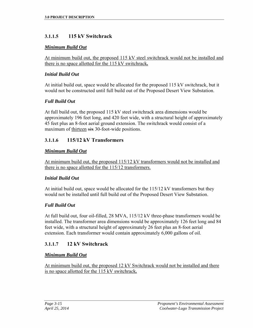
3.0 PROJECT DESCRIPTION
Page 3-15 Proponent’s Environmental Assessment April 25, 2014 Coolwater-Lugo Transmission Project
3.1.1.5 115 kV Switchrack
Minimum Build Out
At minimum build out, the proposed 115 kV steel switchrack would not be installed and there is no space allotted for the 115 kV switchrack.
Initial Build Out
At initial build out, space would be allocated for the proposed 115 kV switchrack, but it would not be constructed until full build out of the Proposed Desert View Substation.
Full Build Out
At full build out, the proposed 115 kV steel switchrack area dimensions would be approximately 196 feet long, and 420 feet wide, with a structural height of approximately 45 feet plus an 8-foot aerial ground extension. The switchrack would consist of a maximum of thirteen six 30-foot-wide positions.
3.1.1.6 115/12 kV Transformers
Minimum Build Out
At minimum build out, the proposed 115/12 kV transformers would not be installed and there is no space allotted for the 115/12 transformers.
Initial Build Out
At initial build out, space would be allocated for the 115/12 kV transformers but they would not be installed until full build out of the Proposed Desert View Substation.
Full Build Out
At full build out, four oil-filled, 28 MVA, 115/12 kV three-phase transformers would be installed. The transformer area dimensions would be approximately 126 feet long and 84 feet wide, with a structural height of approximately 26 feet plus an 8-foot aerial extension. Each transformer would contain approximately 6,000 gallons of oil.
3.1.1.7 12 kV Switchrack
Minimum Build Out
At minimum build out, the proposed 12 kV Switchrack would not be installed and there is no space allotted for the 115 kV switchrack.
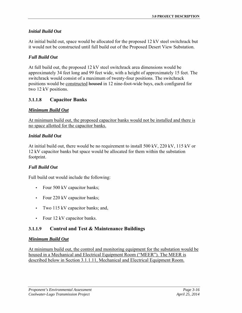
3.0 PROJECT DESCRIPTION
Proponent’s Environmental Assessment Page 3-16 Coolwater-Lugo Transmission Project April 25, 2014
Initial Build Out
At initial build out, space would be allocated for the proposed 12 kV steel switchrack but it would not be constructed until full build out of the Proposed Desert View Substation.
Full Build Out
At full build out, the proposed 12 kV steel switchrack area dimensions would be approximately 34 feet long and 99 feet wide, with a height of approximately 15 feet. The switchrack would consist of a maximum of twenty-four positions. The switchrack positions would be constructed housed in 12 nine-foot-wide bays, each configured for two 12 kV positions.
3.1.1.8 Capacitor Banks
Minimum Build Out
At minimum build out, the proposed capacitor banks would not be installed and there is no space allotted for the capacitor banks.
Initial Build Out
At initial build out, there would be no requirement to install 500 kV, 220 kV, 115 kV or 12 kV capacitor banks but space would be allocated for them within the substation footprint.
Full Build Out
Full build out would include the following:
▪ Four 500 kV capacitor banks;
▪ Four 220 kV capacitor banks;
▪ Two 115 kV capacitor banks; and,
▪ Four 12 kV capacitor banks.
3.1.1.9 Control and Test & Maintenance Buildings
Minimum Build Out
At minimum build out, the control and monitoring equipment for the substation would be housed in a Mechanical and Electrical Equipment Room (“MEER”). The MEER is described below in Section 3.1.1.11, Mechanical and Electrical Equipment Room.
3.0 PROJECT DESCRIPTION
Page 3-17 Proponent’s Environmental Assessment April 25, 2014 Coolwater-Lugo Transmission Project
Initial Build Out
At initial build out, the control and monitoring equipment for the substation would be housed in a Mechanical and Electrical Equipment Room (“MEER”). The MEER is described below in Section 3.1.1.11, Mechanical and Electrical Equipment Room.
Full Build Out
At full build out, the monitoring equipment for the substation would be located in a permanent control building structure that would typically be constructed of concrete block and would include a full basement. The control building dimensions would be approximately 65 feet wide, 60 feet long, and 18 feet high. Full build out would also include a Test & Maintenance Building associated with the Control Building. The Test & Maintenance building dimensions would be approximately 40 feet wide, 89 feet long, and 20 feet high. A permanent restroom would be installed in either the Test & Maintenance Building and/or the Control Building (described below in Section 3.1.1.12, Restroom Facilities).
3.1.1.10 Substation Electrical Power
Minimum Build Out
At minimum build out, the Proposed Desert View Substation would have substation light and power supplied by a 750 kVA distribution transformer, located in proximity to the station light and power rack and/or the main substation MEER. The distribution transformer would be located at the southern end of the substation footprint, and connected and fed from a nearby distribution circuit as described below in initial build out scenario.
Initial Build Out
At initial build out, the Proposed Desert View Substation would have substation light and power supplied by a 750 kVA distribution transformer, located in proximity to the station light and power rack and/or the main substation MEER. The distribution transformer would be located at the southern end of the substation footprint, and connected and fed from a nearby distribution circuit as described below.
A 12 kV tap line would extend north from the existing 12 kV distribution circuit on the south side of Desert View Road. This tap line would travel north, cross over Desert View Road and continue to the substation perimeter wall on the north side of Desert View Road. Just outside of the perimeter wall, the distribution circuit would be transitioned underground and enter the substation through underground ducts and structures. An overhead pole switch would be installed on the tap line prior to the underground transition. The underground circuit would travel through required underground structures, such as a splice boxes and conduit, and finally terminate at the 750 kVA pad mounted transformer located inside the substation. In addition to the 12 kV distribution circuit tap line extension, a distribution capacitor would be installed one span length west of the tap
3.0 PROJECT DESCRIPTION
Proponent’s Environmental Assessment Page 3-18 Coolwater-Lugo Transmission Project April 25, 2014
line on the existing 12 kV distribution circuit. This capacitor would be required to support voltage on the existing distribution circuit.
For construction power, a 75 kVA overhead distribution transformer would be installed on one of the tap line poles located just outside the substation perimeter wall. From that transformer, a line would extend into the substation area and terminate on a distribution panel mounted on a temporary power pole. The temporary power pole would be located in proximity to construction trailers.
Full Build Out
At full build out, the Proposed Desert View Substation would have a total of two independent sources of electrical power, and one backup source. The primary source would be the connection to the tertiary winding of a three-phase power supply (or the AA Bank). The tertiary winding would be connected to a distribution transformer, typically a 750 kVA transformer that would sit on an 8 foot by 10 foot transformer slab box. The second source of power would be the 750 kVA distribution transformer mounted on an 8 foot by 10 foot transformer slab box. The transformer slab box and distribution transformer would be located near the Control Building, within a previously disturbed area of the Proposed Desert View Substation footprint. The 12 kV distribution circuit extension would be further extended from the distribution transformer slab box constructed at initial build out to the relocated 750 kVA distribution substation light and power transformer. This extension would occur entirely within the substation footprint. An additional backup source, for use in case of emergency, would be a 500 kilowatt (“kW”) 120/240 volt three-phase stationary backup generator located within the substation footprint. It would have a fuel tank capable of storing approximately 1,600 gallons of fuel. The stationary generator would be permitted by the Mojave Desert Air Quality Management District (“MDAQMD”).
3.1.1.11 Mechanical and Electrical Equipment Room
Minimum Build Out
At minimum build out, a 220 kV MEER would be constructed within the substation footprint to house the control and monitoring equipment for the substation (see Figure 3.1-A). A MEER is a prefabricated structure that is typically made of steel. SCE anticipates the MEER would have a dark-colored roof and sidewalls, and that the roofline, wall joints, and doorway would have earth-tone trim. Control cable trenches would be installed to connect the MEER to the 220 kV switchrack. The MEER dimensions would be approximately 15 feet high, 60 feet long, and 65 feet wide.
Initial Build Out
At initial build out, a 220 kV MEER would be constructed within the substation footprint to house the control and monitoring equipment for the substation (see Figure 3.1-A). A MEER is a prefabricated structure that is typically made of steel. SCE anticipates the MEER would have a dark-colored roof and sidewalls, and that the roofline, wall joints,
3.0 PROJECT DESCRIPTION
Page 3-19 Proponent’s Environmental Assessment April 25, 2014 Coolwater-Lugo Transmission Project
and doorway would have earth-tone trim. Control cable trenches would be installed to connect the MEER to the 220 kV switchrack. The MEER dimensions would be approximately 15 feet high, 60 feet long, and 65 feet wide.
Full Build Out
At full build out, the 220 kV MEER control and monitoring equipment for the substation would be remotely controlled or relocated to the Control Building, as described in Section 3.1.1.9, Control and Test & Maintenance Buildings. A new 115 kV MEER and 12 kV MEER would be constructed. The 115 kV MEER would have a desert-tan colored roof, sidewalls and exterior door frames, and its dimensions would be approximately 15 feet high, 65 feet long, and 60 feet wide. The 12 kV MEER would have the same exterior colors as the 115 kV MEER, and its dimensions would be approximately 13 feet high, 20 feet long, and 36 feet wide. Control cable trenches would be installed to connect the MEER to the 115 kV and 12 kV switchracks respectively.
3.1.1.12 Restroom Facilities
Minimum Build Out
At minimum build out, the Proposed Desert View Substation would be equipped with a self-contained restroom with a sewage holding tank and a water tank within the substation perimeter enclosure. Water for the restroom would be provided via a water delivery service company or water well, and sewage cleanouts would be maintained by a qualified service company.
Initial Build Out
At initial build out, the Proposed Desert View Substation would be equipped with a self-contained restroom with a sewage holding tank and a water tank within the substation perimeter enclosure. Water for the restroom would be provided via a water delivery service company or water well, and sewage cleanouts would be maintained by a qualified service company.
Full Build Out
At full build out, a new, permanent restroom would be installed at the substation. The restroom would be located inside the Test & Maintenance Building and/or the Control Building. Water for the Proposed Desert View Substation restroom may be provided by either a water well, water delivery service company, or future water line construction. Sewer may be provided by future sewer line construction or a new septic system would be installed and permitted by San Bernardino County.
3.0 PROJECT DESCRIPTION
Proponent’s Environmental Assessment Page 3-20 Coolwater-Lugo Transmission Project April 25, 2014
3.1.1.13 Fire Water Retention Basin and/or Collection System
Minimum Build Out
At minimum build out, transformers would not be installed; therefore, a fire water retention basin and/or collection system would not be needed.
Initial Build Out
At initial build out, transformers would not be installed; therefore, a fire water retention basin and/or collection system would not be needed.
Full Build Out
At full build out, concrete-lined fire water catch basins would be constructed around the 8-foot wide transformer foundations, located on the west and east sides of the Proposed Desert View Substation. The catch basin on the west would be approximately 90 feet wide by 55 feet long and 20 feet deep, and would serve the 500/220 kV transformers; the catch basin on the east would be approximately 45 feet long by 45 feet wide and 18 feet deep, and would serve the 220/115 and 115/12 kV transformers. Underground pipes would be installed to transport water used during firefighting efforts from the transformer areas to the catch basins.
3.1.1.14 Substation Access
Minimum Build Out
Access to the Proposed Desert View Substation would be provided via the existing Wren Street, accessed via the existing Milpas Drive. SCE would pave Wren Street to provide an asphalt concrete access road to the substation driveway. The access road would be approximately 24 feet in width and approximately 3,330 feet in length, with 2-foot wide shoulders. The substation driveway would be asphalt concrete-paved and would extend from the edge of the access road ROW to the substation gate. The driveway would be approximately 40 feet in width and 2,100 feet in length. Secondary access would be provided via the substation’s south entrance located on Desert View Road, which would have an aggregate base surface.
Paved access roads would be maintained by SCE to provide safe access for substation maintenance and operational activities. If road improvements are needed due to wearing and major erosion, pavement rehabilitation would be implemented to ensure safe access to the substation. Under minimum build out scenario, some of the external driveway will need to be removed to expand the substation in the future when the proposed substation is expanded to initial or full build out scenarios.
Initial Build Out
Access to the Proposed Desert View Substation would be provided via the existing Wren Street, accessed via the existing Milpas Drive. SCE would pave Wren Street to provide
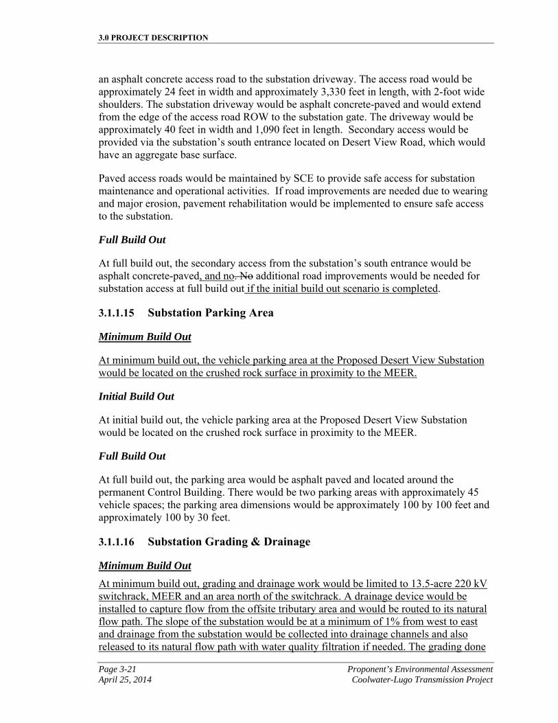
3.0 PROJECT DESCRIPTION
Page 3-21 Proponent’s Environmental Assessment April 25, 2014 Coolwater-Lugo Transmission Project
an asphalt concrete access road to the substation driveway. The access road would be approximately 24 feet in width and approximately 3,330 feet in length, with 2-foot wide shoulders. The substation driveway would be asphalt concrete-paved and would extend from the edge of the access road ROW to the substation gate. The driveway would be approximately 40 feet in width and 1,090 feet in length. Secondary access would be provided via the substation’s south entrance located on Desert View Road, which would have an aggregate base surface.
Paved access roads would be maintained by SCE to provide safe access for substation maintenance and operational activities. If road improvements are needed due to wearing and major erosion, pavement rehabilitation would be implemented to ensure safe access to the substation.
Full Build Out
At full build out, the secondary access from the substation’s south entrance would be asphalt concrete-paved, and no. No additional road improvements would be needed for substation access at full build out if the initial build out scenario is completed.
3.1.1.15 Substation Parking Area
Minimum Build Out
At minimum build out, the vehicle parking area at the Proposed Desert View Substation would be located on the crushed rock surface in proximity to the MEER.
Initial Build Out
At initial build out, the vehicle parking area at the Proposed Desert View Substation would be located on the crushed rock surface in proximity to the MEER.
Full Build Out
At full build out, the parking area would be asphalt paved and located around the permanent Control Building. There would be two parking areas with approximately 45 vehicle spaces; the parking area dimensions would be approximately 100 by 100 feet and approximately 100 by 30 feet.
3.1.1.16 Substation Grading & Drainage
Minimum Build Out
At minimum build out, grading and drainage work would be limited to 13.5-acre 220 kV switchrack, MEER and an area north of the switchrack. A drainage device would be installed to capture flow from the offsite tributary area and would be routed to its natural flow path. The slope of the substation would be at a minimum of 1% from west to east and drainage from the substation would be collected into drainage channels and also released to its natural flow path with water quality filtration if needed. The grading done
3.0 PROJECT DESCRIPTION
Proponent’s Environmental Assessment Page 3-22 Coolwater-Lugo Transmission Project April 25, 2014
for the minimum build out would follow the larger full build out concept, but when the substation would need to be expanded to initial or full build out some demolition work and a large amount of grading will be required. A water well may be needed for the minimum build out.
Initial Build Out
At initial build out, grading and drainage work would be completed at the Proposed Desert View Substation site. Grading would be necessary to prepare the Proposed Desert View Substation site and to install equipment foundations during both initial and full build out.
Grading work at the site could include a retention or detention basin located within the substation perimeter for on-site storm water filtration prior to drainage. Additionally, a permanent water well would be constructed during initial build out for grading activities and future uses. It would be located within the substation property. If it is not feasible to install a permanent water well, water would be imported to the site as needed. Grading within the substation would drain at a minimum of one percent to channels outside of the substation. Drainage channels would route water from the south to the north side of the substation and water would be released through water spreaders. Drainage patterns would remain similar to pre-existing conditions and slope stability measures would be enacted where necessary.
Applicable grading and drainage plans would be prepared and submitted to San Bernardino County for approval prior to construction. The approximate amount and type of ground surface improvements are presented in Section 3.1.1.17, Ground Surface Improvements.
Full Build Out
At full build out, and if the initial build out option is selected, no additional grading and drainage work is anticipated, but the additional substation features would be installed, as presented in Section 3.1.1.17, Ground Surface Improvements.
3.1.1.17 Ground Surface Improvements
The approximate surface area and volumes for the below-grade components of the Proposed Desert View Substation during minimum, initial and full build out are shown in Table 3.1-B, Substation Cut and Fill Grading Summary.
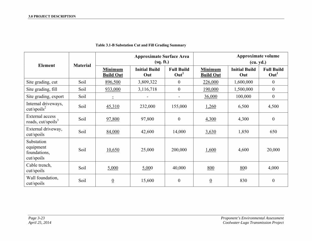
3.0 PROJECT DESCRIPTION
Page 3-23 Proponent’s Environmental Assessment April 25, 2014 Coolwater-Lugo Transmission Project
Table 3.1-B Substation Cut and Fill Grading Summary
Element Material
Approximate Surface Area (sq. ft.)
Approximate volume (cu. yd.)
Minimum Build Out
Initial Build Out
Full Build Out1
Minimum Build Out
Initial Build Out
Full Build Out1
Site grading, cut Soil 896,500 3,809,322 0 226,000 1,600,000 0
Site grading, fill Soil 933,000 3,116,718 0 190,000 1,500,000 0
Site grading, export Soil - - - 36,000 100,000 0
Internal driveways, cut/spoils2
Soil 45,310 232,000 155,000 1,260 6,500 4,500
External access roads, cut/spoils3
Soil 97,800 97,800 0 4,300 4,300 0
External driveway, cut/spoils
Soil 84,000 42,600 14,000 3,630 1,850 650
Substation equipment foundations, cut/spoils
Soil 10,650 25,000 200,000 1,600 4,600 20,000
Cable trench, cut/spoils
Soil 5,000 5,000 40,000 800 800 4,000
Wall foundation, cut/spoils
Soil 0 15,600 0 0 830 0
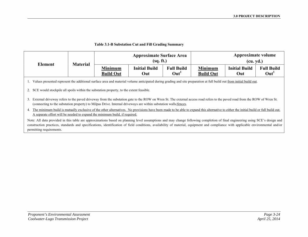
3.0 PROJECT DESCRIPTION
Proponent’s Environmental Assessment Page 3-24 Coolwater-Lugo Transmission Project April 25, 2014
Table 3.1-B Substation Cut and Fill Grading Summary
Element Material
Approximate Surface Area (sq. ft.)
Approximate volume (cu. yd.)
Minimum Build Out
Initial Build Out
Full Build Out1
Minimum Build Out
Initial Build Out
Full Build Out1
1. Values presented represent the additional surface area and material volume anticipated during grading and site preparation at full build out from initial build out.
2. SCE would stockpile all spoils within the substation property, to the extent feasible.
3. External driveway refers to the paved driveway from the substation gate to the ROW on Wren St. The external access road refers to the paved road from the ROW of Wren St. (connecting to the substation property) to Milpas Drive. Internal driveways are within substation walls/fences.
4. The minimum build is mutually exclusive of the other alternatives. No provisions have been made to be able to expand this alternative to either the initial build or full build out. A separate effort will be needed to expand the minimum build, if required.
Note: All data provided in this table are approximations based on planning level assumptions and may change following completion of final engineering using SCE’s design and construction practices, standards and specifications, identification of field conditions, availability of material, equipment and compliance with applicable environmental and/or permitting requirements.
3.0 PROJECT DESCRIPTION
Page 3-25 Proponent’s Environmental Assessment April 25, 2014 Coolwater-Lugo Transmission Project
Ground surface of the Proposed Desert View Substation site would be finished with materials imported to the site and excavated on the site. The approximate surface area and volumes of these materials are listed below in Table 3.1-C, Substation Ground Surface Improvement Materials.

3.0 PROJECT DESCRIPTION
Proponent’s Environmental Assessment Page 3-26 Coolwater-Lugo Transmission Project April 25, 2014
This page is intentionally blank
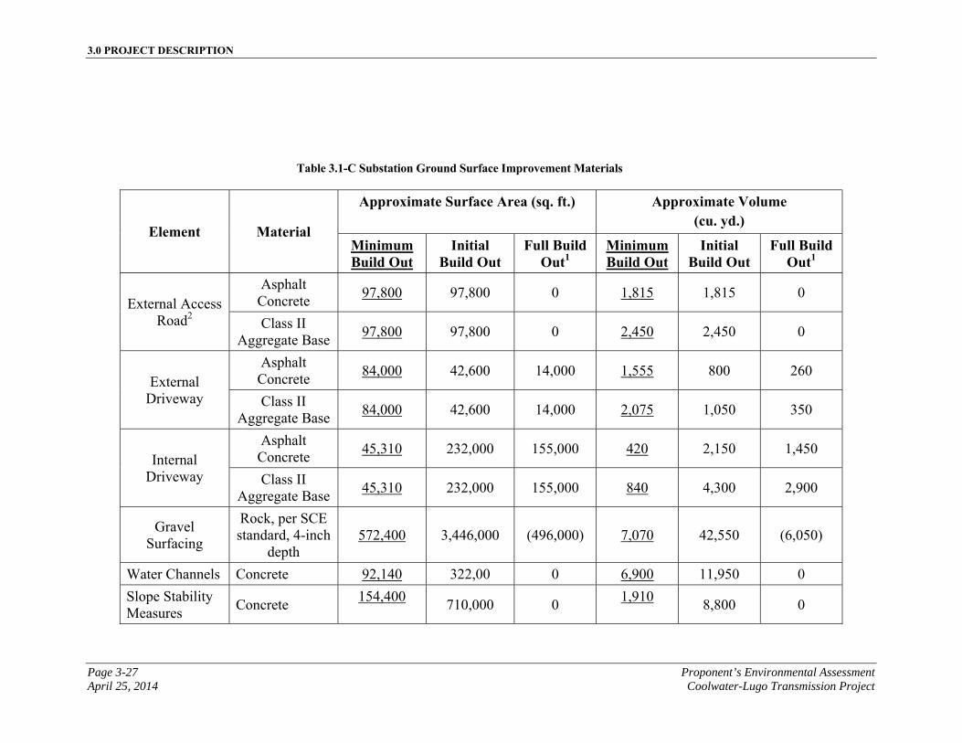
3.0 PROJECT DESCRIPTION
Page 3-27 Proponent’s Environmental Assessment April 25, 2014 Coolwater-Lugo Transmission Project
Table 3.1-C Substation Ground Surface Improvement Materials
Element Material
Approximate Surface Area (sq. ft.) Approximate Volume (cu. yd.)
Minimum Build Out
Initial Build Out
Full Build Out1
Minimum Build Out
Initial Build Out
Full Build Out1
External Access Road2
Asphalt Concrete
97,800 97,800 0 1,815 1,815 0
Class II Aggregate Base
97,800 97,800 0 2,450 2,450 0
External Driveway
Asphalt Concrete
84,000 42,600 14,000 1,555 800 260
Class II Aggregate Base
84,000 42,600 14,000 2,075 1,050 350
Internal Driveway
Asphalt Concrete
45,310 232,000 155,000 420 2,150 1,450
Class II Aggregate Base
45,310 232,000 155,000 840 4,300 2,900
Gravel Surfacing
Rock, per SCE standard, 4-inch
depth 572,400 3,446,000 (496,000) 7,070 42,550 (6,050)
Water Channels Concrete 92,140 322,00 0 6,900 11,950 0
Slope Stability Measures
Concrete 154,400
710,000 0 1,910
8,800 0
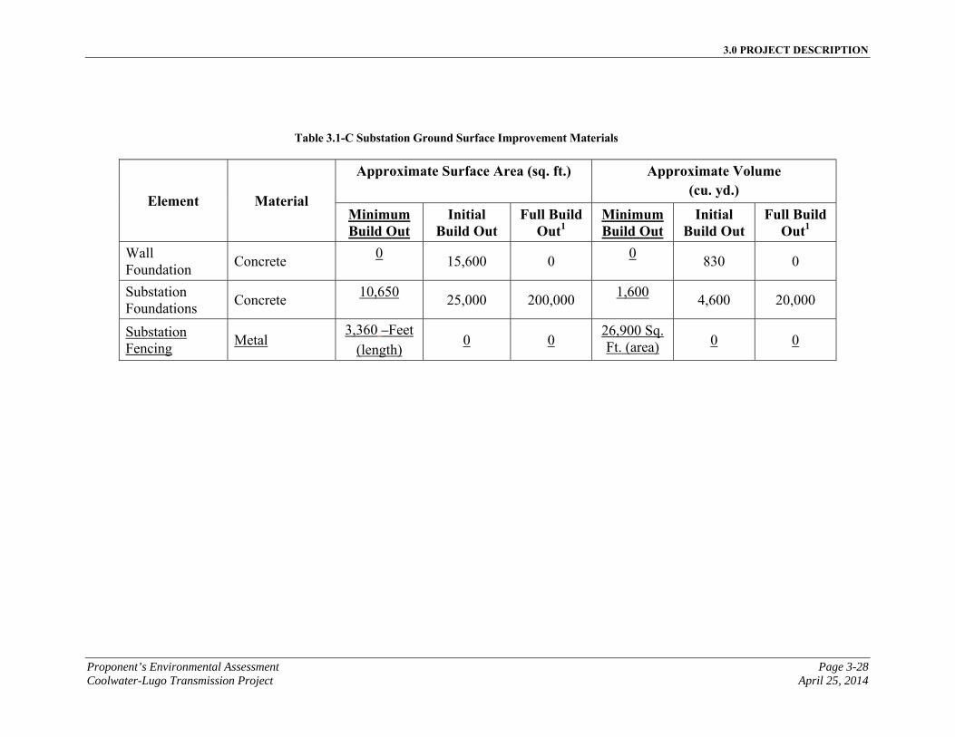
3.0 PROJECT DESCRIPTION
Proponent’s Environmental Assessment Page 3-28 Coolwater-Lugo Transmission Project April 25, 2014
Table 3.1-C Substation Ground Surface Improvement Materials
Element Material
Approximate Surface Area (sq. ft.) Approximate Volume (cu. yd.)
Minimum Build Out
Initial Build Out
Full Build Out1
Minimum Build Out
Initial Build Out
Full Build Out1
Wall Foundation
Concrete 0
15,600 0 0
830 0
Substation Foundations
Concrete 10,650
25,000 200,000 1,600
4,600 20,000
Substation Fencing
Metal 3,360 Feet
(length) 0 0
26,900 Sq. Ft. (area) 0 0
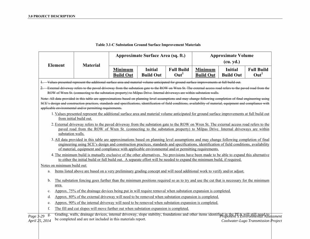
3.0 PROJECT DESCRIPTION
Page 3-29 Proponent’s Environmental Assessment April 25, 2014 Coolwater-Lugo Transmission Project
Table 3.1-C Substation Ground Surface Improvement Materials
Element Material
Approximate Surface Area (sq. ft.) Approximate Volume (cu. yd.)
Minimum Build Out
Initial Build Out
Full Build Out1
Minimum Build Out
Initial Build Out
Full Build Out1
1. Values presented represent the additional surface area and material volume anticipated for ground surface improvements at full build out.
2. External driveway refers to the paved driveway from the substation gate to the ROW on Wren St. The external access road refers to the paved road from the ROW of Wren St. (connecting to the substation property) to Milpas Drive. Internal driveways are within substation walls.
Note: All data provided in this table are approximations based on planning level assumptions and may change following completion of final engineering using SCE’s design and construction practices, standards and specifications, identification of field conditions, availability of material, equipment and compliance with applicable environmental and/or permitting requirements.
1. Values presented represent the additional surface area and material volume anticipated for ground surface improvements at full build out from initial build out.
2. External driveway refers to the paved driveway from the substation gate to the ROW on Wren St. The external access road refers to the paved road from the ROW of Wren St. (connecting to the substation property) to Milpas Drive. Internal driveways are within substation walls.
3. All data provided in this table are approximations based on planning level assumptions and may change following completion of final engineering using SCE’s design and construction practices, standards and specifications, identification of field conditions, availability of material, equipment and compliance with applicable environmental and/or permitting requirements.
4. The minimum build is mutually exclusive of the other alternatives. No provisions have been made to be able to expand this alternative to either the initial build or full build out. A separate effort will be needed to expand the minimum build, if required.
Notes on minimum build out:
a. Items listed above are based on a very preliminary grading concept and will need additional work to verify and/or adjust.
b. The substation fencing goes further than the minimum positions required so as to try and use the cut that is necessary for the minimum area.
c. Approx. 75% of the drainage devices being put in will require removal when substation expansion is completed.
d. Approx. 80% of the external driveway will need to be removed when substation expansion is completed.
e. Approx. 90% of the internal driveway will need to be removed when substation expansion is completed.
f. The fill and cut slopes will move further out when substation expansion is completed.
g. Grading, walls, drainage devices, internal driveway, slope stability, foundations and other items identified in the PEA will still need to be completed and are not included in this materials report.

3.0 PROJECT DESCRIPTION
Proponent’s Environmental Assessment Page 3-30 Coolwater-Lugo Transmission Project April 25, 2014
This page is intentionally blank
3.0 PROJECT DESCRIPTION
Page 3-31 Proponent’s Environmental Assessment April 25, 2014 Coolwater-Lugo Transmission Project
3.1.1.18 Substation Lighting
Minimum and Initial Build Out
For minimum, initial and full build out of the Proposed Desert View Substation, lighting would consist of light-emitting diode (“LED”) luminaires located in the switchracks around the transformer banks and in areas of the yard where operating and maintenance activities may take place during evening hours for emergency/scheduled work. Maintenance lights would be controlled by a manual switch and would normally be in the “off” position. The maintenance lights would be directed downward to reduce glare outside the facility. A light, indicating the operation of the rolling gate, would automatically turn on once the gate begins to open and would turn off shortly after the gate is closed.
Full Build Out
At full build out, additional lighting would be needed for area and roadway illumination. The additional lighting would be located on the substation equipment and along the internal driveways. All lighting would consist of LED luminaires and would be controlled by manual switches and would normally be in the “off” position as described for initial build out.
3.1.1.19 Substation Perimeter
Minimum Build Out
At minimum build out, the Proposed Desert View Substation would be enclosed on all sides by 8 foot high metal fence with barbed wire and visible razor wire affixed to the top. Two 40’ gates would be placed at the primary and secondary entrances and a 4-foot personnel walk-in gate would also be installed.
Initial Build Out
At initial build out, the Proposed Desert View Substation would be enclosed on all sides by an 8-foot prefabricated concrete panel wall with two 40-foot rolling driveway gates and one 4-foot personnel walk-in gate. Barbed wire and visible razor wire would be affixed to the top of the panel walls. These perimeter enclosure requirements are based on current SCE substation standards for employee and facility safety and security. Should homeland security requirements increase, more conservative perimeter enclosure standards may be needed, which could include patrols by armed security guards.
If needed, prior to initial build out substation construction, SCE would develop an appropriate landscaping plan in conformance with San Bernardino County standards. A landscaping plan would be submitted for review by San Bernardino County. If needed, landscaping would be established after approval of the landscaping plan and completion of the Proposed Desert View Substation.
3.0 PROJECT DESCRIPTION
Proponent’s Environmental Assessment Page 3-32 Coolwater-Lugo Transmission Project April 25, 2014
Full Build Out
At full build out, if the initial build out scenario is completed, no additional perimeter structure and/or entry gates are expected based on current SCE substation standards. If the initial build out scenario is completed, Nno additional components are expected to be installed or constructed for the substation perimeter with the exception of the asphalt concrete paving of the secondary access to the substation’s southern entrance, as described in Section 3.1.1.14, Substation Access.
3.1.2 Modifications to Existing Substations Description
The Proposed Project would require modifications and other major work at existing and future SCE substations, including the existing Coolwater Switchyard, the existing Lugo Substation, and the future Jasper Substation1.
3.1.2.1 Coolwater Switchyard
Modifications:
▪ Reconfigure the existing 220 kV line terminations at the existing Coolwater Switchyard to accommodate the new 220 kV transmission line to the Proposed Desert View Substation;
▪ Equip a 220 kV position with circuit breakers and disconnect switches and terminate a new Coolwater-Desert View 220 kV transmission line; and,
▪ Relocate existing fiber-optic cables.
Other Major Work:
▪ Install two separate MEERs in the Coolwater 220 kV and 115 kV switchracks and move SCE equipment from the adjacent NRG Energy, Inc.2 MEER to SCE MEERs;
▪ Install new telecommunication equipment, including the following major components:
o New direct current (“DC”) batteries and powerboard
1 The future Jasper Substation would be triggered by a generation interconnection project and would be processed under a separate Permit to Construct. Modifications at future Jasper Substation would only be required if Jasper Substation received a Permit to Construct prior to construction of the Coolwater-Lugo Transmission Project. If Jasper were to be constructed after completion of the Coolwater-Lugo Transmission Project, the Jasper construction activities would be associated with the Jasper Permit to Construct.
2 NRG Energy, Inc. (formerly GenOn) is the operator of the Coolwater Generating Station immediately adjacent to the SCE Coolwater Switchyard.
3.0 PROJECT DESCRIPTION
Page 3-33 Proponent’s Environmental Assessment April 25, 2014 Coolwater-Lugo Transmission Project
o New lightwave equipment
o New channel bank equipment
o New data network equipment
o New microwave tower and foundation
o New microwave antenna and waveguide
o New microwave radio
o New miscellaneous telecommunication equipment, cable tray, fiber tray, etc.
o New OPGW fiber-optic cable
o Remove portion of abandoned fire water line to provide space for new MEERs at Coolwater Switchyard
3.1.2.2 Lugo Substation
Modifications:
▪ The following modification would be completed at the Lugo Substation 500 kV bus: (Full Build Out Only)
▪ Extend the bus and reconfigure the existing 500 kV line terminations to accommodate a new Desert View-Lugo 220 kV-operated (500 kV-constructed) transmission line and new Lugo No.3AA 500/220 kV transformer bank (Full Build Out Only);
▪ Equip a position with circuit breakers and disconnect switches for the new Lugo No. 3AA 500/220 kV transformer bank (Full Build Out Only)
▪ Install Spill Prevention and Control Countermeasures (“SPCC”) containment if needed (Full Build Out Only)
▪ The following modification would be completed at the Lugo Substation 220 kV bus:
▪ Extend the bus and reconfigure the existing 220 kV line terminations to accommodate a new Desert View-Lugo 220 kV-operated (500 kV-constructed) transmission line and new Lugo No.3AA 500/220 kV transformer bank (Full Build Out Only)
▪ Equip a 220 kV position with circuit breakers and disconnect switches, and install a new Lugo No. 3AA 500/220 kV transformer bank (Full Build Only)
3.0 PROJECT DESCRIPTION
Proponent’s Environmental Assessment Page 3-34 Coolwater-Lugo Transmission Project April 25, 2014
▪ Equip a 220 kV position with circuit breakers and disconnect switches, and terminate a new Desert View-Lugo 220 kV-operated (500 kV-constructed) transmission line
▪ Remove Pisgah #1 220 kV Transmission Line from position 6 and remove tie breaker from position 6
▪ Remove Pisgah #2 220 kV Transmission Line from Position 2
▪ Install new 220 kV line from Desert View on Lugo 220 kV Position 2W
▪ Install SPCC containment, if needed
Other Major Work:
▪ Install a new Control Building, approximately 18 feet high by 165 long by 80 feet wide
▪ Install new telecommunication equipment including:
o New lightwave equipment
o New channel bank equipment
▪ New OPGW fiber-optic cable
▪ Replace line protection with new SEL 311L & L90 dual pilot
3.1.2.3 Future Jasper Substation
The future Jasper Substation would be triggered by a generation interconnection project and would be processed under a separate Permit to Construct. The future Jasper Substation is considered in Chapter 6 under the Cumulative Impacts analysis. The future Jasper Substation is assumed to be constructed after the Coolwater-Lugo Transmission Project, and under that assumption, the modifications described below would not be required. If the future Jasper Substation was operational prior to construction of the Proposed Project, the following modifications would be completed at Jasper Substation:
Modifications:
▪ Equip a 220 kV position with circuit breakers and disconnect switches, and terminate a new Coolwater-Jasper No.1 220 kV transmission line
Other Major Work:
▪ Install new telecommunication equipment including:
▪ New lightwave equipment
3.0 PROJECT DESCRIPTION
Page 3-35 Proponent’s Environmental Assessment April 25, 2014 Coolwater-Lugo Transmission Project
▪ New channel bank equipment
▪ New OPGW fiber-optic cable
3.1.3 500 kV and 220 kV Transmission Line Description
The Proposed Project would include the following 500 kV transmission line elements: one segment of single-circuit and double-circuit 500 kV construction (“Segment 7”) initially energized at 220 kV. New lattice steel towers (“LSTs”), as well as H-Frame (two-pole), and single-circuit and double-circuit Tubular Steel Poles (“TSPs”) (single-pole) would be installed to accommodate the new transmission line segment, predominately located within existing ROW and some new ROW. Construction would also include removal of existing towers on the Lugo-Pisgah No. 1 and 2 220 kV lines between existing Lugo Substation and Proposed Desert View Substation.
Proposed Transmission Line Segment 7 would originate at the Proposed Desert View Substation and would extend southwest in the existing SCE transmission corridor to the existing Lugo Substation. Segment 7 would also include one smaller sub-segment, into the southwest side of the Proposed Desert View Substation from the existing Lugo-Pisgah No. 1 and No. 2 line ROW, approximately 0.6 mile, which would be removed after build out of the 500 kV portion of Desert View Substation.1 Segment 7, including the sub-segment, would be approximately 16.6 miles in length and would be predominately located in the existing Lugo-Pisgah No. 1 and No. 2 line ROW.
The Proposed 500 kV Transmission Line Route (Segment 7) would consist of galvanized structures, with a dulled finish, that would support a single-circuit transmission line. Each phase of the circuit would consist of a two-conductor bundle of 2156 kcmil ACSR non-specular conductors. The bundled conductors would be arranged in a horizontal configuration. OPGWand potentially Overhead Ground Wire (“OHGW”) would be installed on top of the structures to provide protection and to support telecommunication.
The Proposed Project would also include the following 220 kV transmission line elements: six segments of double-circuit 220 kV construction (Segments 1, 2, 3, 5, 5A, and 12). New LSTs as well as TSP H-Frames (two-pole), single-circuit, and double-circuit TSPs (single-pole and three-pole) would be installed to accommodate the new 220 kV transmission line segments, located within a combination of new and existing ROW. Construction would also include removal of existing towers on the Lugo-Pisgah No. 1 line between the area southwest of the intersection of Haynes Road and SR-247, and Proposed Desert View Substation. Additionally, construction would include double-circuit structures from the intersection of Haynes Road and SR-247 west to Proposed Desert View Substation.
1 The sub-segment and the associated structures would be removed once the 500 kV portion of Desert View Substation is built out. For purposes of analyzing the worst case environmental impact of the Proposed Project, it is included as part of Segment 7 of the Proposed Transmission Line Route.
3.0 PROJECT DESCRIPTION
Proponent’s Environmental Assessment Page 3-36 Coolwater-Lugo Transmission Project April 25, 2014
For minimum build out, one side of the double circuit 220 kV structures would be strung in Segments 1, 2, 3 and 12. Additionally, for Segments 5, 5A both sides of the double circuit 220 kV structures would be strung.
For initial and full build out, both sides of the double circuit 220 kV structures would be strung in Segments 1, 2, 3, 5, 5A and 12.
Proposed Transmission Line Segment 12 would connect to the existing Coolwater Switchyard. Segment 12 would exit the west side of the Coolwater Switchyard and then extend south crossing a Burlington Northern Santa Fe (“BNSF”) railroad track, National Trails Highway, Needles Freeway (“I-40”) and continuing south of I-40. Segment 12 would be approximately 1.4 miles in length, within new ROW.
Proposed Transmission Line Segment 1 would originate just south of I-40 and continue south to the north-easterly corner of the intersection of Power Line Road and Camp Rock Road. Segment 1 would parallel the Los Angeles Department of Water and Power (“LADWP”) transmission corridor in a southwesterly direction. For purposes of this analysis, SCE is proposing Segment 1 would cross under the LADWP corridor northeast of the intersection of the corridor and Camp Rock Road and then would follow the south side of the corridor, crossing SR-247 and continuing to a point just west of Stoddard Wells Road1. Segment 1 would be approximately 17.0 miles in length, within new ROW.
Proposed Transmission Line Segment 2 would originate at the intersection of the LADWP transmission corridor and Stoddard Wells Road and would extend south paralleling Stoddard Wells Road until it intersects with Lucerne Valley Cutoff Road. From this point, Segment 2 would extend southeast paralleling the Lucerne Valley Cutoff Road to a point just west of the intersection of Lucerne Valley Cutoff Road and SR-247. Segment 2 would be approximately 11.7 miles in length, within new ROW.
Proposed Transmission Line Segment 3 would originate at the intersection of Lucerne Valley Cutoff Road and SR-247 and would extend generally south southeast paralleling the west side of SR-247 and would terminate northwest of the intersection of SR-247 and Haynes Roads (approximate location of future Jasper Substation). Segment 3 would be approximately 3.9 miles in length, within new ROW.
Proposed Transmission Line Segment 5 would originate just northwest of the intersection of Haynes Road and SR-247 and would extend generally south in new ROW until crossing under existing SCE transmission lines and then would head southwest in the existing SCE transmission corridor, where it would replace a portion of the existing Lugo-Pisgah No. 1 line. Within the existing corridor, Segment 5 would cross State Route 18 (“SR-18”) near Bernard Road and would continue southwest to a point just west of the intersection of Desert View Road and Milpas Drive. Segment 5 would be approximately 12.9 miles in length, predominately located within existing ROW.
1 The specific crossing location under the LADWP corridor is subject to final engineering and the outcome of consultation with LADWP.
3.0 PROJECT DESCRIPTION
Page 3-37 Proponent’s Environmental Assessment April 25, 2014 Coolwater-Lugo Transmission Project
Proposed Transmission Line Segment 5A would originate just west of the intersection of Desert View Road and Milpas Drive and would extend generally northwest to terminate in the east side of the Proposed Desert View Substation. Segment 5A would be approximately 0.7 mile in length. The proposed segment would be within new ROW.
The Proposed 220 kV Transmission Segments would consist of galvanized structures, with a dulled finish, that would support a double-circuit transmission line. Each phase of the circuit would consist of a two-conductor bundle of 1590 kcmil ACSR non-specular conductors. The bundled conductors would be arranged in a horizontal configuration. OPGW and potentially OHGW would be installed on top of the structures to provide protection and to support telecommunication. The Proposed Transmission Line Route is presented on Figure 3.1-B, Proposed Transmission Line Route; the approximate dimensions of the proposed structure types are shown in Figure 3.1-C, Transmission Structures, and summarized in Table 3.1-D, Typical Transmission Structure Dimensions.

3.0 PROJECT DESCRIPTION
Proponent’s Environmental Assessment Page 3-38 Coolwater-Lugo Transmission Project April 25, 2014
This page is intentionally blank
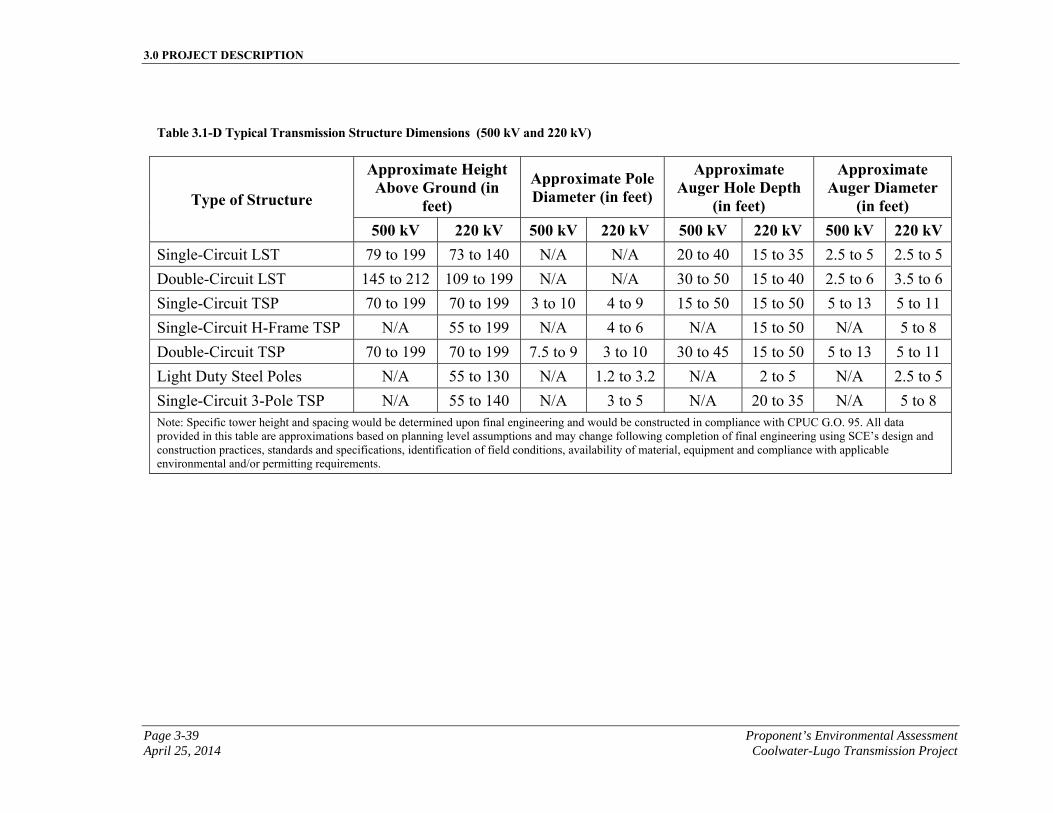
3.0 PROJECT DESCRIPTION
Page 3-39 Proponent’s Environmental Assessment April 25, 2014 Coolwater-Lugo Transmission Project
Table 3.1-D Typical Transmission Structure Dimensions (500 kV and 220 kV)
Type of Structure
Approximate Height Above Ground (in
feet)
Approximate Pole Diameter (in feet)
Approximate Auger Hole Depth
(in feet)
Approximate Auger Diameter
(in feet) 500 kV 220 kV 500 kV 220 kV 500 kV 220 kV 500 kV 220 kV
Single-Circuit LST 79 to 199 73 to 140 N/A N/A 20 to 40 15 to 35 2.5 to 5 2.5 to 5
Double-Circuit LST 145 to 212 109 to 199 N/A N/A 30 to 50 15 to 40 2.5 to 6 3.5 to 6
Single-Circuit TSP 70 to 199 70 to 199 3 to 10 4 to 9 15 to 50 15 to 50 5 to 13 5 to 11
Single-Circuit H-Frame TSP N/A 55 to 199 N/A 4 to 6 N/A 15 to 50 N/A 5 to 8
Double-Circuit TSP 70 to 199 70 to 199 7.5 to 9 3 to 10 30 to 45 15 to 50 5 to 13 5 to 11
Light Duty Steel Poles N/A 55 to 130 N/A 1.2 to 3.2 N/A 2 to 5 N/A 2.5 to 5
Single-Circuit 3-Pole TSP N/A 55 to 140 N/A 3 to 5 N/A 20 to 35 N/A 5 to 8 Note: Specific tower height and spacing would be determined upon final engineering and would be constructed in compliance with CPUC G.O. 95. All data provided in this table are approximations based on planning level assumptions and may change following completion of final engineering using SCE’s design and construction practices, standards and specifications, identification of field conditions, availability of material, equipment and compliance with applicable environmental and/or permitting requirements.

3.0 PROJECT DESCRIPTION
Proponent’s Environmental Assessment Page 3-40 Coolwater-Lugo Transmission Project April 25, 2014
This page is intentionally blank.
3.0 PROJECT DESCRIPTION
Page 3-41 Proponent’s Environmental Assessment April 25, 2014 Coolwater-Lugo Transmission Project
All transmission facilities would be designed to be avian-safe, following the intent of the Suggested Practices for Avian Protection on Power Lines: the State of the Art in 2006 (Avian Power Line Interaction Committee, 2006). All transmission facilities would be evaluated for potential collision risk and, where determined to be high risk, lines would be marked with collision reduction devices in accordance with Mitigating Bird Collisions with Power Lines: The State of the Art in 2006 (Avian Power Line Interaction Committee 2006).
Approximately 69 single-circuit LSTs would be used for the Proposed 500 kV Transmission Line (Segment 7). The LSTs would extend approximately 79 feet to 199 feet above ground. Each LST would be attached to four concrete foundations that would be approximately 2.5 feet to 5 feet in diameter and would extend underground approximately 20 feet to 40 feet with up to approximately 1 foot to 4 feet of concrete visible above ground. The LSTs would be all steel structures with a dulled galvanized finish.1
Approximately four double-circuit LSTs would be used for the Proposed 500 kV Transmission Line (Segment 7) just outside of Desert View Substation and Lugo Substation. The LSTs would extend approximately 145 feet to 212 feet above ground. Each LST would be attached to four concrete foundations that would be 2.5 feet to 6 feet in diameter and would extend underground approximately 30 feet to 50 feet with up to approximately 1 foot to 4 feet of concrete visible above ground. The LSTs would be all steel structures with a dulled galvanized finish.
Approximately four double-circuit TSPs would be used for the Proposed 500 kV Transmission Line. The TSPs would be approximately 3 feet to 10 feet in diameter at the base and extend approximately 70 feet to 199 feet above ground. The TSPs would be attached to concrete foundations that would be approximately 5 feet to 13 feet in diameter
1 Steel lattice transmission structures require a continuous electrical path through each steel element to ground for personnel safety and mitigate the impact of short circuits or lighting strikes. This electrical path is achieved when the individual galvanized steel elements are securely bolted together. Coloring of steel lattice structure elements prior to assembly will hamper or impede this continuous electric path because it creates an insulator between the elements. Color applications to lattice steel structures would need to be applied following assembly of the individual pieces. This would mean that a paint product would need to be used as a finishing step in the field. Painting in the field is undesirable for several reasons. The paint would have to be applied in the open air causing volatile organic compound emissions and possible spills of paint. Paint has a life cycle much shorter than the structure therefore the towers would have to be re-painted several times over the life of the project. Each time the towers are painted there would be additional impacts to get to the tower sites, scrape off the loose paint and apply new paint. In addition, SCE no longer proposes various shades of gray in the galvanizing dulling process because the process was not repeatable from multiple steel suppliers. SCE now only proposes natural gray galvanizing with dulling. SCE has found that the natural light gray that the galvanize coating will reach through weathering has the best visual appearance and blends best with desert and mountain backgrounds.
3.0 PROJECT DESCRIPTION
Proponent’s Environmental Assessment Page 3-42 Coolwater-Lugo Transmission Project April 25, 2014
and would extend underground approximately 15 feet to 50 feet with up to approximately 1 foot to 4 feet of concrete visible above ground. The TSPs would be all steel structures with a dulled galvanized finish.
Approximately 267 double-circuit LSTs would be used for the Proposed 220 kV Transmission Line (Segments 1, 2, 3, 5, 5A, and 12). The LSTs would extend approximately 109 feet to 199 feet above ground. Each LST would be attached to four concrete foundations that would be approximately 3.5 feet to 6 feet in diameter and would extend underground approximately 15 feet to 40 feet with up to approximately 1 foot to 4 feet of concrete visible above ground. The LSTs would be all steel structures with a dulled galvanized finish.
Approximately five single-circuit TSPs and six double-circuit TSPs would be used for the Proposed 220 kV Transmission Line. The TSPs would be approximately 3 feet to 10 feet in diameter at the base and extend approximately 70 feet to 199 feet above ground. The TSPs would be attached to concrete foundations that would be approximately 5 feet to 11 feet in diameter and would extend underground approximately 15 feet to 50 feet with up to approximately 1 foot to 4 feet of concrete visible above ground. The TSPs would be all steel structures with a dulled galvanized finish.
Approximately 18 single-circuit H-frame TSPs would be used for the Proposed 220 kV Transmission Line. The H-frame TSPs would be approximately 4 feet to 6 feet in diameter at the base and extend approximately 55 feet to 199 feet above ground. The TSPs would be attached to concrete foundations that would be approximately 5 feet to 8 feet in diameter and would extend underground approximately 15 feet to 50 feet with up to approximately 1 foot to 4 feet of concrete visible above ground. The TSPs would be all steel structures with a dulled galvanized finish.
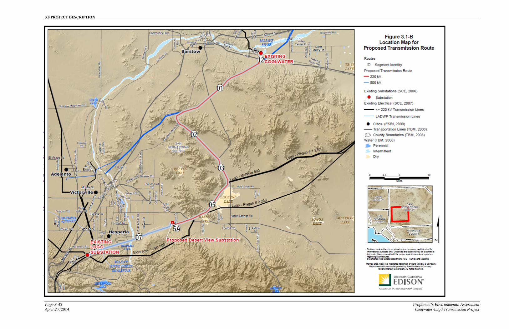
3.0 PROJECT DESCRIPTION
Page 3-43 Proponent’s Environmental Assessment April 25, 2014 Coolwater-Lugo Transmission Project
Figure 3.1-A Proposed Transmission Line Route
3.0 PROJECT DESCRIPTION
Proponent’s Environmental Assessment Page 3-44 Coolwater-Lugo Transmission Project April 25, 2014
This page is intentionally blank.
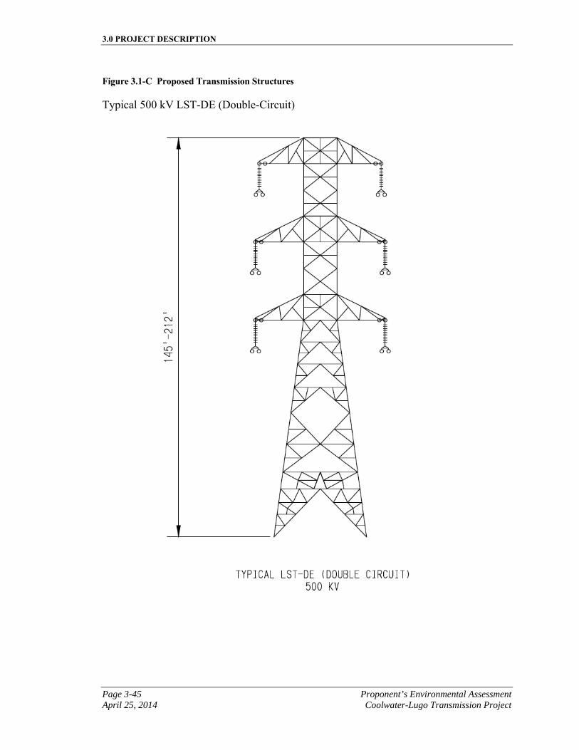
3.0 PROJECT DESCRIPTION
Page 3-45 Proponent’s Environmental Assessment April 25, 2014 Coolwater-Lugo Transmission Project
Figure 3.1-C Proposed Transmission Structures
Typical 500 kV LST-DE (Double-Circuit)
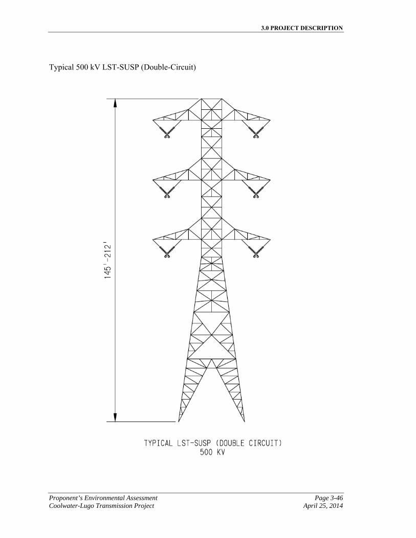
3.0 PROJECT DESCRIPTION
Proponent’s Environmental Assessment Page 3-46 Coolwater-Lugo Transmission Project April 25, 2014
Typical 500 kV LST-SUSP (Double-Circuit)
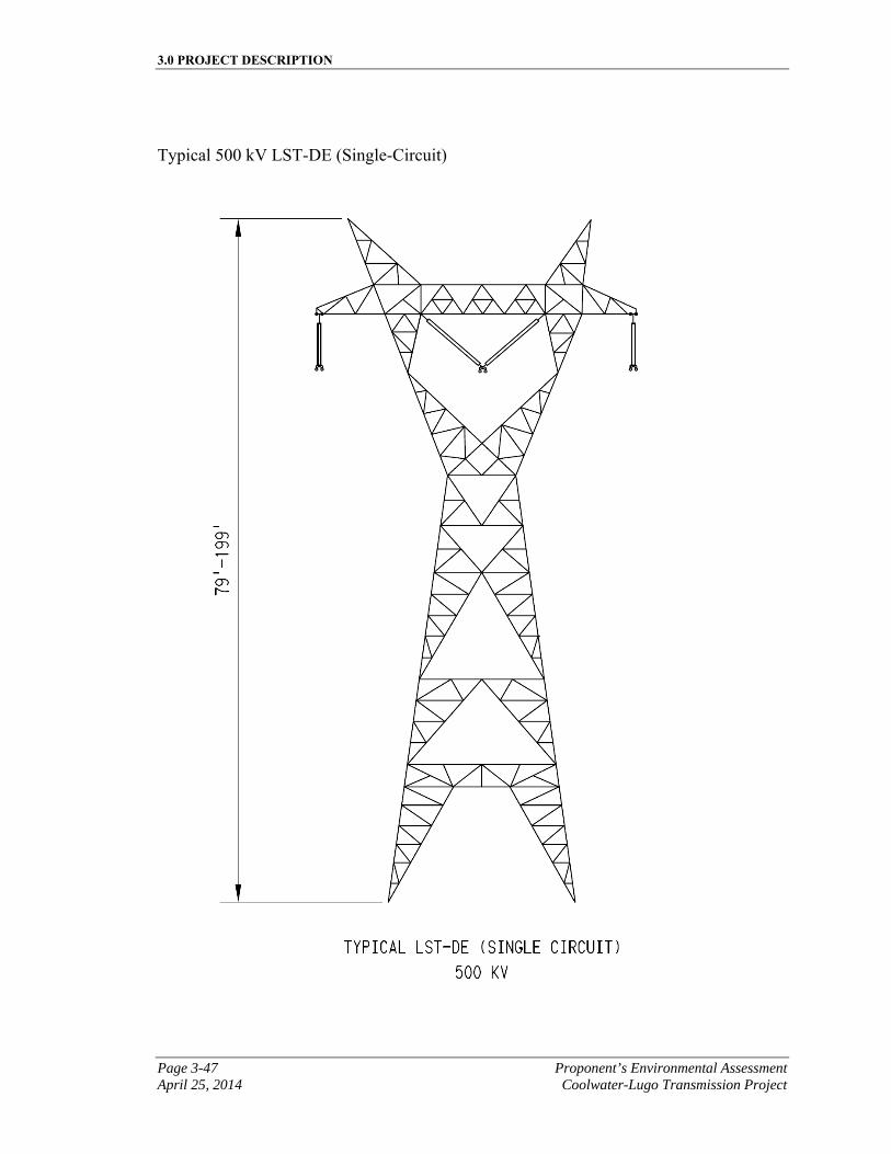
3.0 PROJECT DESCRIPTION
Page 3-47 Proponent’s Environmental Assessment April 25, 2014 Coolwater-Lugo Transmission Project
Typical 500 kV LST-DE (Single-Circuit)
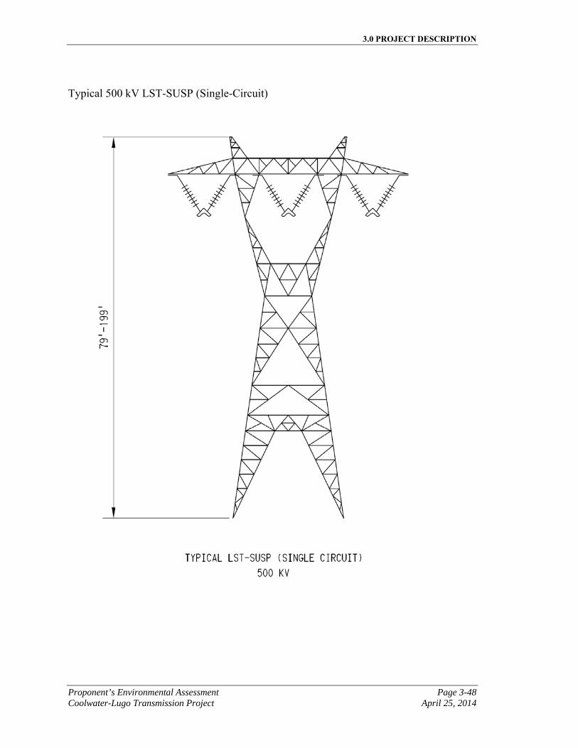
3.0 PROJECT DESCRIPTION
Proponent’s Environmental Assessment Page 3-48 Coolwater-Lugo Transmission Project April 25, 2014
Typical 500 kV LST-SUSP (Single-Circuit)
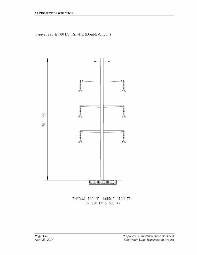
3.0 PROJECT DESCRIPTION
Page 3-49 Proponent’s Environmental Assessment April 25, 2014 Coolwater-Lugo Transmission Project
Typical 220 & 500 kV TSP-DE (Double-Circuit)
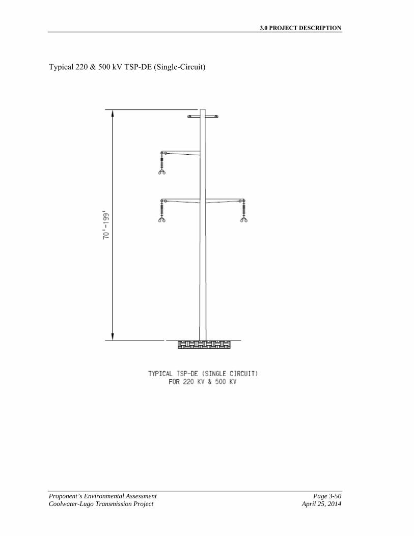
3.0 PROJECT DESCRIPTION
Proponent’s Environmental Assessment Page 3-50 Coolwater-Lugo Transmission Project April 25, 2014
Typical 220 & 500 kV TSP-DE (Single-Circuit)
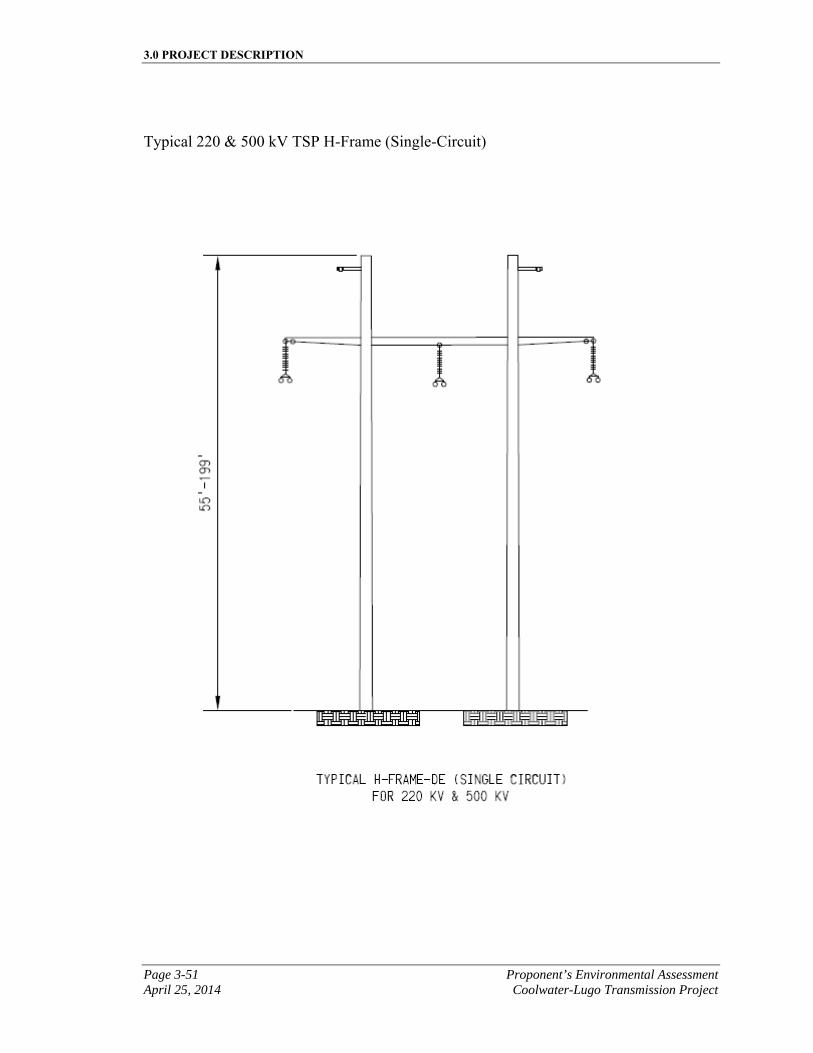
3.0 PROJECT DESCRIPTION
Page 3-51 Proponent’s Environmental Assessment April 25, 2014 Coolwater-Lugo Transmission Project
Typical 220 & 500 kV TSP H-Frame (Single-Circuit)
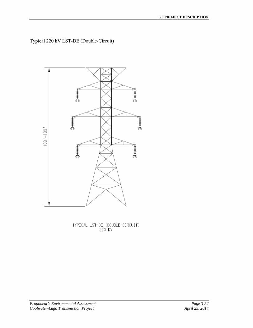
3.0 PROJECT DESCRIPTION
Proponent’s Environmental Assessment Page 3-52 Coolwater-Lugo Transmission Project April 25, 2014
Typical 220 kV LST-DE (Double-Circuit)
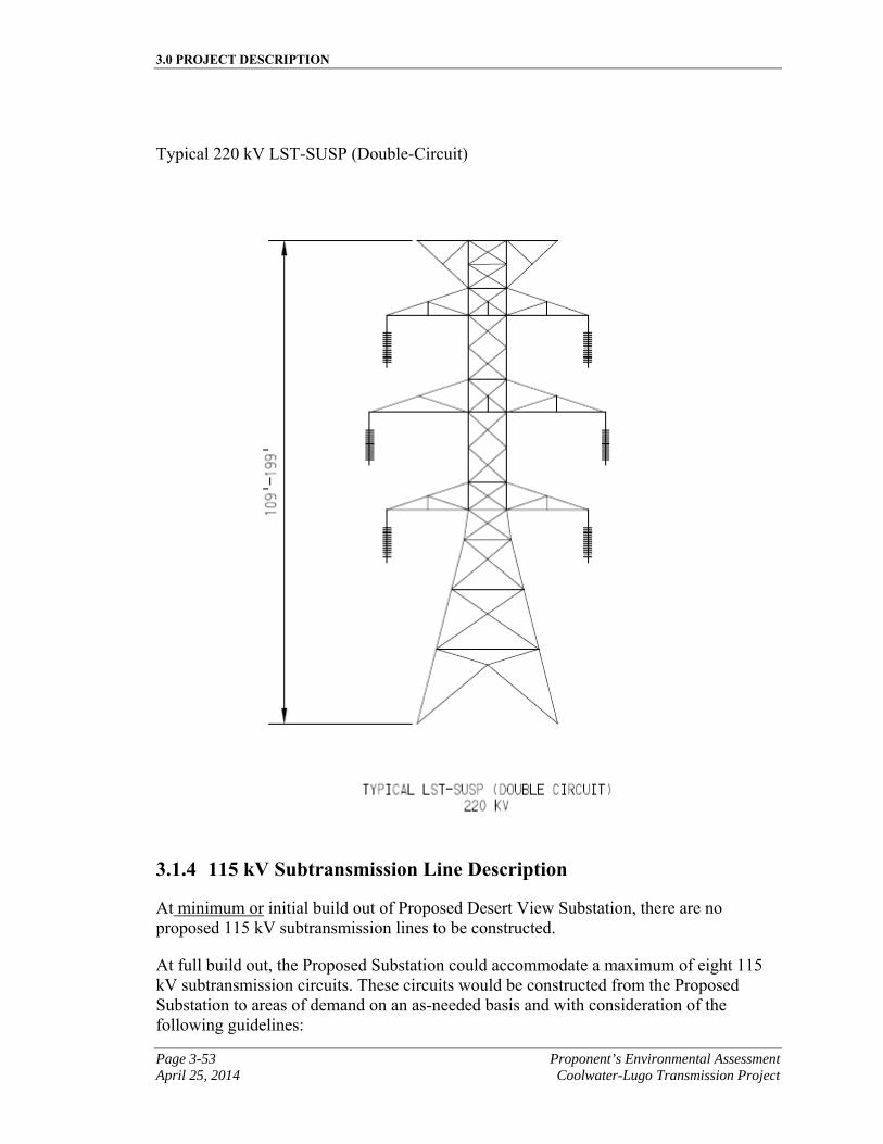
3.0 PROJECT DESCRIPTION
Page 3-53 Proponent’s Environmental Assessment April 25, 2014 Coolwater-Lugo Transmission Project
Typical 220 kV LST-SUSP (Double-Circuit)
3.1.4 115 kV Subtransmission Line Description
At minimum or initial build out of Proposed Desert View Substation, there are no proposed 115 kV subtransmission lines to be constructed.
At full build out, the Proposed Substation could accommodate a maximum of eight 115 kV subtransmission circuits. These circuits would be constructed from the Proposed Substation to areas of demand on an as-needed basis and with consideration of the following guidelines:
3.0 PROJECT DESCRIPTION
Proponent’s Environmental Assessment Page 3-54 Coolwater-Lugo Transmission Project April 25, 2014
▪ The location of the current load growth;
▪ Existing electrical subtransmission facilities in the area; and
▪ The location of roads and existing SCE ROWs.
These 115 kV subtransmission circuits cannot be designed at this time due to the uncertainty of where load relief will be needed and where future load growth will precisely occur, in addition to unforeseen changes in the physical and environmental condition of the surrounding area. Accordingly, the location and routing of each of these potential 115 kV subtransmission circuits would be determined in accordance with CPUC G.O. 131-D in the future.
3.1.4.1 Subtransmission Getaways
As part of the minimum or initial build out, no subtransmission getaways would be constructed at the Proposed Desert View Substation.
The full build out of the Proposed Desert View Substation could include up to eight subtransmission getaways. Getaways could either exit the substation overhead or underground. They would most likely exit the substation on the eastern side.
If the subtransmission getaways exited the substation overhead, approximately eight TSPs would be used for the Proposed Project at full build out. The TSPs would be approximately 2 to 4 feet in diameter at the base and extend approximately 50 feet to 100 feet above ground. The TSPs would be attached to concrete foundations that would be approximately 5 to 7 feet in diameter and would extend underground approximately 20 to 40 feet with up to approximately 4 feet of concrete visible above ground. Each TSP foundation would use approximately 11 to 300 cubic yards of concrete. The TSPs would be all galvanized steel structures with a dulled finish.
The subtransmission getaways could also exit underground. Underground getaways would require installation of up to eight vaults. A minimum of 10 feet would be required between conduit duct runs. Each duct run would consist of seven 5-inch conduits with a minimum of 36 inches of cover. Up to eight 75 to 100-foot tall engineered steel riser poles may be required to bring the getaway circuits out of the substation. The underground installation is further described in Section 3.1.5.2, Underground Subtransmission Line Installation.
Conductor size, and total pole count are speculative at this time, but this information would be provided in accordance with CPUC G.O. 131-D in the future.
3.1.5 Subtransmission Line Relocations
▪ The relocation or modifications of existing 115 kV subtransmission lines could be required for the construction of the Proposed Project. The 115 kV relocations or modifications could include any of the following: relocation, removal of idle facilities, structure modifications, or undergrounding of facilities. The final
3.0 PROJECT DESCRIPTION
Page 3-55 Proponent’s Environmental Assessment April 25, 2014 Coolwater-Lugo Transmission Project
determination of the number of transmission crossings that would impact existing subtransmission facilities would be based upon assessments of CPUC G.O. 95 requirements during final engineering. Potential subtransmission work associated with relocations or modifications is described in the following section.
3.1.5.1 Subtransmission Structure Types
The subtransmission structures needed as a result of relocations or modifications for the Proposed Project may utilize TSPs (single pole and three-pole), LWS poles, TSP H frames, wood poles, or underground vaults and conduit.
3.1.5.2 Underground Subtransmission Line Installation
The following section describes the typical construction activities associated with installing the potential underground 115 kV subtransmission lines at locations where crossings on the Proposed Project would warrant undergrounding. The final determination of the number of crossing locations where undergrounding of the existing subtransmission facilities would be necessary, would be based upon CPUC G.O. 95 clearance requirement assessments during final engineering.
Survey
Construction activities would begin with the survey of existing underground utilities at the locations where the Proposed Transmission Line Route crosses existing subtransmission lines and undergrounding of the existing subtransmission lines is determined to be necessary. SCE would notify all applicable utilities via underground service alert to locate and mark existing utilities, and would conduct exploratory excavations (potholing) as necessary to verify the location of existing utilities. SCE would secure necessary permits for survey, as required.
Trenching
Each of the Proposed Project’s crossings could include a total of approximately 1,000 feet of new underground 115 kV subtransmission lines and associated transition and support structures, except where indicated below in the individual crossing descriptions. An approximately 20-24 inch wide by 60-inch deep trench would be required to place the 115 kV subtransmission line underground. This depth is required to meet the minimum 36 inches of cover above the duct bank. Trenching may be performed by using the following general steps, including but not limited to: mark the location and applicable underground utilities, lay out trench line, saw cut asphalt or concrete pavement as necessary, dig to appropriate depth with a backhoe or similar equipment, and install duct bank. Once the duct bank has been installed, the trench would be backfilled with a two-sack sand slurry mix. Excavated materials would be used as described in Section 3.7, Reusable, Recyclable, and Waste Material Management. Should groundwater be encountered, it would be pumped into a tank and disposed of at an off-site disposal facility in accordance with all applicable laws.
3.0 PROJECT DESCRIPTION
Proponent’s Environmental Assessment Page 3-56 Coolwater-Lugo Transmission Project April 25, 2014
The trench for underground construction would be widened and shored where appropriate to meet California Occupation and Safety Health Administration requirements. Trenching would be staged so that open trench lengths would not exceed that which is required to install the duct banks. Where needed, open trench sections would have steel plates placed over them in order to maintain vehicular and pedestrian traffic. Provisions for emergency vehicle access would be arranged with local jurisdictions in advance of construction activities. SCE would secure necessary permits for trenching, as required.
Duct Bank Installation
As trenching for the underground 115 kV subtransmission line crossings is completed, SCE would begin to install the underground duct bank. Collectively, the duct bank is comprised of cable conduit, spacers, ground wire, and concrete encasement. The duct bank typically consists of seven 5-inch diameter polyvinyl chloride (“PVC”) conduits fully encased with a minimum of 3 inches of concrete all around. Typical 115 kV subtransmission duct bank installations would accommodate six cables plus one for telecommunications. The Proposed Project would utilize three cable conduits and leave three spare cable conduits for any potential future circuits pursuant to SCE’s current standards for 115 kV underground construction.
The majority of the 115 kV duct banks would be installed in a vertically stacked configuration and each duct bank would be approximately 21 inches in height by 20 inches in width. In areas where underground utilities are highly congested or areas where it is necessary to fan out the conduits to reach termination structures, a flat configuration duct bank may be required. However, for the Proposed Project it is not anticipated that a flat underground duct bank configuration would be required.
In instances where a subtransmission duct bank would cross or run parallel to other substructures that operate at normal soil temperature (gas lines, telephone lines, water mains, storm drains, sewer lines), a minimal radial clearance of 6 inches for crossing and 12 inches for paralleling these substructures would be required, respectively. Where duct banks cross or run parallel to substructures that operate at temperatures significantly exceeding normal soil temperature (other underground transmission circuits, primary distribution cables, steam lines, heated oil lines), additional radial clearance may be required. Clearances and depths would meet requirements set forth within Rule 41.4 of CPUC G.O. 128.
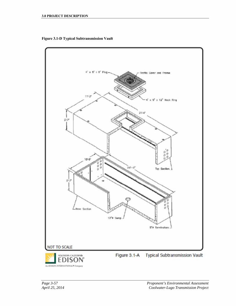
3.0 PROJECT DESCRIPTION
Page 3-57 Proponent’s Environmental Assessment April 25, 2014 Coolwater-Lugo Transmission Project
Figure 3.1-D Typical Subtransmission Vault
3.0 PROJECT DESCRIPTION
Proponent’s Environmental Assessment Page 3-58 Coolwater-Lugo Transmission Project April 25, 2014
Vault Installation
Vaults are below-grade concrete enclosures where the duct banks terminate. The vaults are constructed of prefabricated steel-reinforced concrete and designed to withstand heavy truck traffic loading. The inside dimensions of the underground vaults would be approximately 10 feet wide by 20 feet long with an inside height of 9.5 feet. Each underground crossing would have two vaults unless indicated otherwise in the individual crossing descriptions. The vaults would be placed no more than 1,500 feet apart along the underground portion of the subtransmission source line. See Figure 3.1-D for a typical subtransmission vault.
Initially, the vaults would be used as pulling locations to pull cable through the conduits. After the cable is installed, the vaults would be utilized to splice the cables together. During operation, manholes to the vaults would provide access to the underground cables for maintenance, inspections, and repairs.
Installation of each vault would take place over approximately a one-week period depending on soil conditions. First, the vault pit would be excavated and shored; a minimum of 6 inches of mechanically compacted aggregate base would be placed to cover the entire bottom of the pit, followed by delivery and installation of the vault. Once the vault is set, grade rings and the vault casting would be added and set to match the existing grade. The excavated area would be backfilled with a sand slurry mix to a point just below the top of the vault roof. Excavated materials, if suitable, would be used to backfill the remainder of the excavation and any excess materials would be used as described in Section 3.7, Reusable, Recyclable, and Waste Material Management. Finally, the excavated area would be restored as required.
Cable Pulling, Splicing, Termination
Following vault and duct bank installation, SCE would pull the electrical cables through the duct banks, splice the cable segments at each vault, and terminate cables at the transition structures where the subtransmission line would transition from underground to overhead. To pull the cables through the duct banks, a cable reel would be placed at one end of the conduit segment, and a pulling rig would be placed at the opposite end. The cable from the cable reel would be attached to a rope or steel cable in the duct bank, and the rope linked to the pulling rig, which would pull the rope and the attached cable through the duct banks. A lubricant would be applied as the cable enters the ducts to decrease friction and facilitate travel through the PVC conduits. The electrical cables for the 115 kV subtransmission line circuit would be pulled through the individual conduits in the duct bank at a rate of two to three conduits between vaults per day.
After cable pulling is completed, the electrical cables would be spliced together. A splice crew would conduct splicing operations at each vault location and continue until all splicing is completed.
3.0 PROJECT DESCRIPTION
Page 3-59 Proponent’s Environmental Assessment April 25, 2014 Coolwater-Lugo Transmission Project
Riser Pole Installation
At each end of an underground segment, the cables would rise out of the ground on a riser pole, which accommodates the transition from underground to overhead subtransmission lines. Riser poles constructed as part of the Proposed Project would consist of engineered TSP structures unless indicated otherwise in the individual crossing descriptions. The riser pole would support cable terminations, lightning arresters, and dead-end hardware for overhead conductors. Construction methods for these structures would be substantially similar to those described in Section 3.2.3.6, Tubular Steel Pole Installation.
3.1.5.3 Proposed Project Subtransmission Line Crossings Description
SCE has identified potential crossings, relocations and/or idling of existing 115 kV subtransmission facilities on Segment 1, 5 and 7 of the Proposed Transmission Line Route. The potential work associated with these locations is described below by route segment.
Segment 12 Crossings
Crossing S12-A: Coolwater-Gale 115 kV Line
At this location, work would likely include transfer of the existing skyline down to the new interset poles the same as the conductor, either to an arm position or to the top of the pole. The exact position would be determined in final engineering.
Crossing S12-B: Ivanpah Eldorado-Baker-Coolwater-Dunn Siding-Mountain Pass 115 kV Line
Typical subtransmission structure dimensions for Crossing S12-B are presented in Table 3.1-E, Typical Subtransmission Structure Dimensions for Crossing S12-B. The process would include removal of approximately one existing LST and installation of approximately six new LWS or wood poles with additional guys as required. The poles would be direct buried to a depth of approximately 8.5 to 10 feet below the ground surface and extend approximately 57 to 70 feet above the ground. The diameter of the poles would be approximately 1 to 3 feet at ground level and would taper to the top of the pole.
SCE would only use an underground option to meet G.O. 95 requirements if applicable. If applicable, the underground subtransmission line installation would be similar to as previously described.
3.0 PROJECT DESCRIPTION
Proponent’s Environmental Assessment Page 3-60 Coolwater-Lugo Transmission Project April 25, 2014
Table 3.1-E Typical Subtransmission Structure Dimensions for Crossing S12-B
Pole Type
Proposed Number
of Structures
Approximate Height Above
Ground
Approximate Pole
Diameter
Approximate Auger hole
Depth
Approximate Auger
Diameter
LWS or Wood Poles
6 57 to 70 feet 1 to 3 feet 8.5 to 10 feet 24 to 30 inches
Crossing S12-C: Coolwater-Segs 2 -Tortilla 115 kV Line
Typical subtransmission structure dimensions for Crossing S12-C are presented in Table 3.1-F, Typical Subtransmission Structure Dimensions for Crossing S12-C. The process would include installation of approximately two new LWS or wood poles with additional guys as required. The poles would be direct buried to a depth of approximately 7 to 9 feet below the ground surface and extend approximately 43 to 61 feet above the ground. The diameter of the poles would be approximately 1 to 3 feet at ground level and would taper to the top of the pole.
SCE would only use an underground option to meet G.O. 95 requirements if applicable. If applicable, the underground subtransmission line installation would be similar to as previously described.
Table 3.1- F Typical Subtransmission Structure Dimensions for Crossing S12-C
Pole Type
Proposed Number
of Structures
Approximate Height Above
Ground
Approximate Pole
Diameter
Approximate Auger hole
Depth
Approximate Auger
Diameter
LWS or Wood Poles
6 43 to 61 feet 1 to 3 feet 7 to 9 feet 24 to 30 inches
Segment 5 Crossings
Crossing S5-A: Cottonwood-Savage 115 kV Line
Typical subtransmission structure dimensions for Crossing S5-A are presented in Table 3.1-G, Typical Subtransmission Structure Dimensions for Crossing S5-A. The process would include removal of approximately eleven existing wood poles and installation of approximately five new LWS or wood poles with additional guys as required. The poles would be direct buried to a depth of approximately 7 to 9 feet below the ground surface and extend approximately 43 to 61 feet above the ground. The diameter of the poles would be approximately 1 to 3 feet at ground level and would taper to the top of the pole.
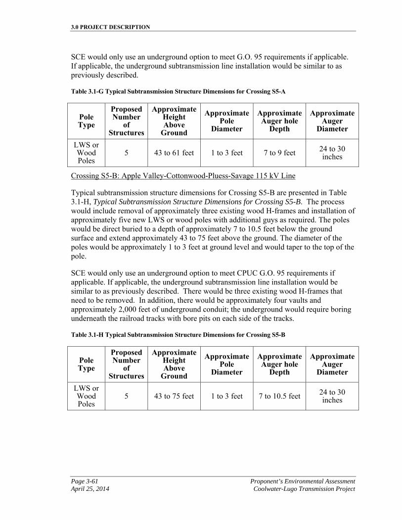
3.0 PROJECT DESCRIPTION
Page 3-61 Proponent’s Environmental Assessment April 25, 2014 Coolwater-Lugo Transmission Project
SCE would only use an underground option to meet G.O. 95 requirements if applicable. If applicable, the underground subtransmission line installation would be similar to as previously described.
Table 3.1-G Typical Subtransmission Structure Dimensions for Crossing S5-A
Pole Type
Proposed Number
of Structures
Approximate Height Above
Ground
Approximate Pole
Diameter
Approximate Auger hole
Depth
Approximate Auger
Diameter
LWS or Wood Poles
5 43 to 61 feet 1 to 3 feet 7 to 9 feet 24 to 30 inches
Crossing S5-B: Apple Valley-Cottonwood-Pluess-Savage 115 kV Line
Typical subtransmission structure dimensions for Crossing S5-B are presented in Table 3.1-H, Typical Subtransmission Structure Dimensions for Crossing S5-B. The process would include removal of approximately three existing wood H-frames and installation of approximately five new LWS or wood poles with additional guys as required. The poles would be direct buried to a depth of approximately 7 to 10.5 feet below the ground surface and extend approximately 43 to 75 feet above the ground. The diameter of the poles would be approximately 1 to 3 feet at ground level and would taper to the top of the pole.
SCE would only use an underground option to meet CPUC G.O. 95 requirements if applicable. If applicable, the underground subtransmission line installation would be similar to as previously described. There would be three existing wood H-frames that need to be removed. In addition, there would be approximately four vaults and approximately 2,000 feet of underground conduit; the underground would require boring underneath the railroad tracks with bore pits on each side of the tracks.
Table 3.1-H Typical Subtransmission Structure Dimensions for Crossing S5-B
Pole Type
Proposed Number
of Structures
Approximate Height Above
Ground
Approximate Pole
Diameter
Approximate Auger hole
Depth
Approximate Auger
Diameter
LWS or Wood Poles
5 43 to 75 feet 1 to 3 feet 7 to 10.5 feet 24 to 30 inches
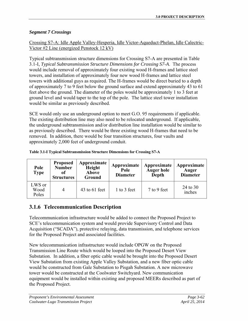
3.0 PROJECT DESCRIPTION
Proponent’s Environmental Assessment Page 3-62 Coolwater-Lugo Transmission Project April 25, 2014
Segment 7 Crossings
Crossing S7-A: Idle Apple Valley-Hesperia, Idle Victor-Aqueduct-Phelan, Idle Calectric-Victor #2 Line (energized Penstock 12 kV)
Typical subtransmission structure dimensions for Crossing S7-A are presented in Table 3.1-I, Typical Subtransmission Structure Dimensions for Crossing S7-A. The process would include removal of approximately four existing wood H-frames and lattice steel towers, and installation of approximately four new wood H-frames and lattice steel towers with additional guys as required. The H-frames would be direct buried to a depth of approximately 7 to 9 feet below the ground surface and extend approximately 43 to 61 feet above the ground. The diameter of the poles would be approximately 1 to 3 feet at ground level and would taper to the top of the pole. The lattice steel tower installation would be similar as previously described.
SCE would only use an underground option to meet G.O. 95 requirements if applicable. The existing distribution line may also need to be relocated underground. If applicable, the underground subtransmission and/or distribution line installation would be similar to as previously described. There would be three existing wood H-frames that need to be removed. In addition, there would be four transition structures, four vaults and approximately 2,000 feet of underground conduit.
Table 3.1-I Typical Subtransmission Structure Dimensions for Crossing S7-A
Pole Type
Proposed Number
of Structures
Approximate Height Above
Ground
Approximate Pole
Diameter
Approximate Auger hole
Depth
Approximate Auger
Diameter
LWS or Wood Poles
4 43 to 61 feet 1 to 3 feet 7 to 9 feet 24 to 30 inches
3.1.6 Telecommunication Description
Telecommunication infrastructure would be added to connect the Proposed Project to SCE’s telecommunication system and would provide Supervisory Control and Data Acquisition (“SCADA”), protective relaying, data transmission, and telephone services for the Proposed Project and associated facilities.
New telecommunication infrastructure would include OPGW on the Proposed Transmission Line Route which would be looped into the Proposed Desert View Substation. In addition, a fiber optic cable would be brought into the Proposed Desert View Substation from existing Apple Valley Substation, and a new fiber optic cable would be constructed from Gale Substation to Pisgah Substation. A new microwave tower would be constructed at the Coolwater Switchyard. New communication equipment would be installed within existing and proposed MEERs described as part of the Proposed Project.
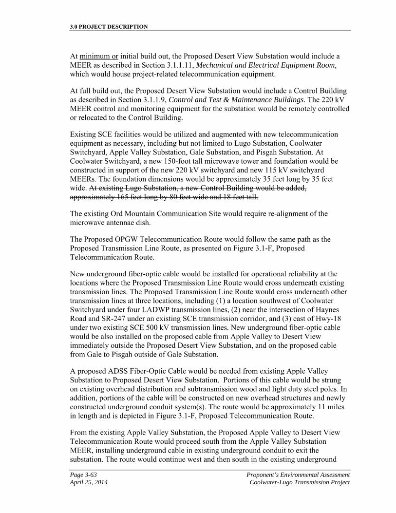
3.0 PROJECT DESCRIPTION
Page 3-63 Proponent’s Environmental Assessment April 25, 2014 Coolwater-Lugo Transmission Project
At minimum or initial build out, the Proposed Desert View Substation would include a MEER as described in Section 3.1.1.11, Mechanical and Electrical Equipment Room, which would house project-related telecommunication equipment.
At full build out, the Proposed Desert View Substation would include a Control Building as described in Section 3.1.1.9, Control and Test & Maintenance Buildings. The 220 kV MEER control and monitoring equipment for the substation would be remotely controlled or relocated to the Control Building.
Existing SCE facilities would be utilized and augmented with new telecommunication equipment as necessary, including but not limited to Lugo Substation, Coolwater Switchyard, Apple Valley Substation, Gale Substation, and Pisgah Substation. At Coolwater Switchyard, a new 150-foot tall microwave tower and foundation would be constructed in support of the new 220 kV switchyard and new 115 kV switchyard MEERs. The foundation dimensions would be approximately 35 feet long by 35 feet wide. At existing Lugo Substation, a new Control Building would be added, approximately 165 feet long by 80 feet wide and 18 feet tall.
The existing Ord Mountain Communication Site would require re-alignment of the microwave antennae dish.
The Proposed OPGW Telecommunication Route would follow the same path as the Proposed Transmission Line Route, as presented on Figure 3.1-F, Proposed Telecommunication Route.
New underground fiber-optic cable would be installed for operational reliability at the locations where the Proposed Transmission Line Route would cross underneath existing transmission lines. The Proposed Transmission Line Route would cross underneath other transmission lines at three locations, including (1) a location southwest of Coolwater Switchyard under four LADWP transmission lines, (2) near the intersection of Haynes Road and SR-247 under an existing SCE transmission corridor, and (3) east of Hwy-18 under two existing SCE 500 kV transmission lines. New underground fiber-optic cable would be also installed on the proposed cable from Apple Valley to Desert View immediately outside the Proposed Desert View Substation, and on the proposed cable from Gale to Pisgah outside of Gale Substation.
A proposed ADSS Fiber-Optic Cable would be needed from existing Apple Valley Substation to Proposed Desert View Substation. Portions of this cable would be strung on existing overhead distribution and subtransmission wood and light duty steel poles. In addition, portions of the cable will be constructed on new overhead structures and newly constructed underground conduit system(s). The route would be approximately 11 miles in length and is depicted in Figure 3.1-F, Proposed Telecommunication Route.
From the existing Apple Valley Substation, the Proposed Apple Valley to Desert View Telecommunication Route would proceed south from the Apple Valley Substation MEER, installing underground cable in existing underground conduit to exit the substation. The route would continue west and then south in the existing underground
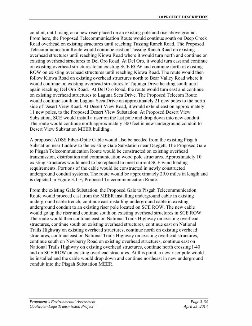
3.0 PROJECT DESCRIPTION
Proponent’s Environmental Assessment Page 3-64 Coolwater-Lugo Transmission Project April 25, 2014
conduit, until rising on a new riser placed on an existing pole and rise above ground. From here, the Proposed Telecommunication Route would continue south on Deep Creek Road overhead on existing structures until reaching Tussing Ranch Road. The Proposed Telecommunication Route would continue east on Tussing Ranch Road on existing overhead structures until reaching Kiowa Road where it would turn north and continue on existing overhead structures to Del Oro Road. At Del Oro, it would turn east and continue on existing overhead structures to an existing SCE ROW and continue north in existing ROW on existing overhead structures until reaching Kiowa Road. The route would then follow Kiowa Road on existing overhead structures north to Bear Valley Road where it would continue on existing overhead structures to Tujunga Drive heading south until again reaching Del Oro Road. At Del Oro Road, the route would turn east and continue on existing overhead structures to Laguna Seca Drive. The Proposed Telecom Route would continue south on Laguna Seca Drive on approximately 21 new poles to the north side of Desert View Road. At Desert View Road, it would extend east on approximately 11 new poles, to the Proposed Desert View Substation. At Proposed Desert View Substation, SCE would install a riser on the last pole and drop down into new conduit. The route would continue north approximately 500 feet in new underground conduit to Desert View Substation MEER building.
A proposed ADSS Fiber-Optic Cable would also be needed from the existing Pisgah Substation near Ludlow to the existing Gale Substation near Daggett. The Proposed Gale to Pisgah Telecommunication Route would be constructed on existing overhead transmission, distribution and communication wood pole structures. Approximately 10 existing structures would need to be replaced to meet current SCE wind loading requirements. Portions of the cable would be constructed in newly constructed underground conduit systems. The route would be approximately 29.0 miles in length and is depicted in Figure 3.1-F, Proposed Telecommunication Route.
From the existing Gale Substation, the Proposed Gale to Pisgah Telecommunication Route would proceed east from the MEER installing underground cable in existing underground cable trench, continue east installing underground cable in existing underground conduit to an existing riser pole located on SCE ROW. The new cable would go up the riser and continue south on existing overhead structures in SCE ROW. The route would then continue east on National Trails Highway on existing overhead structures, continue south on existing overhead structures, continue east on National Trails Highway on existing overhead structures, continue north on existing overhead structures, continue east on National Trails Highway on existing overhead structures, continue south on Newberry Road on existing overhead structures, continue east on National Trails Highway on existing overhead structures, continue north crossing I-40 and on SCE ROW on existing overhead structures. At this point, a new riser pole would be installed and the cable would drop down and continue northeast in new underground conduit into the Pisgah Substation MEER.
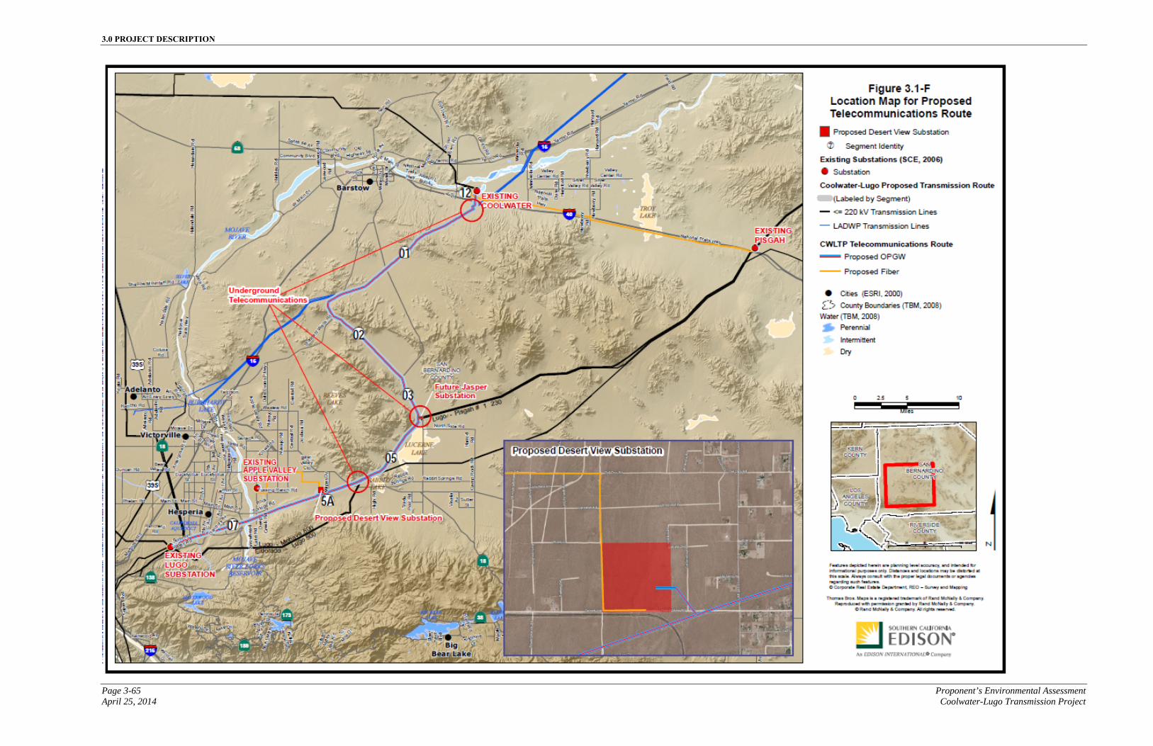
3.0 PROJECT DESCRIPTION
Page 3-65 Proponent’s Environmental Assessment April 25, 2014 Coolwater-Lugo Transmission Project
Figure 3.1-F Proposed Telecommunication Route

3.0 PROJECT DESCRIPTION
Proponent’s Environmental Assessment Page 3-66 Coolwater-Lugo Transmission Project April 25, 2014
This page is intentionally blank.
3.0 PROJECT DESCRIPTION
Page 3-67 Proponent’s Environmental Assessment April 25, 2014 Coolwater-Lugo Transmission Project
3.1.7 Distribution
At minimum or initial build out, there are no new proposed 12 kV distribution circuits to be constructed, with the exception of the 12 kV distribution line extension described in Section 3.1.1.10, Substation Electrical Power.
At full build out, the proposed substation could accommodate a maximum of sixteen distribution circuits operated at 12 kV. These distribution circuits would be constructed from the proposed substation to areas of demand on an as-needed basis and with consideration of the following guidelines:
▪ The location of the current load growth;
▪ Existing electrical distribution facilities in the area; and
▪ The location of roads and existing SCE ROWs.
These 12 kV distribution circuits cannot be designed at this time due to the uncertainty of where load relief will be needed and where future load growth will precisely occur, in addition to unforeseen changes in the physical and environmental condition of the surrounding area. Accordingly, the exact location and routing of each of these proposed 12 kV distribution circuits would be exempt from CPUC approval per G.O. 131-D and determined in the future for full build out. Additionally, design of the circuit routes requires the most complete and comprehensive details that can be provided by other utilities regarding their existing and planned infrastructure in the area. The locations of these facilities will impact the ultimate electrical distribution circuit routes. This information must be provided at an appropriate stage in the design of the distribution circuits, to minimize design conflicts and construction delays due to additional changes.
3.1.7.1 Distribution Getaways1
At minimum or initial build out, no distribution getaways would be constructed.
At full build out, underground duct banks would be built from the north and south ends of the 12 kV cable trenches (adjacent to the 12 kV rack) to accommodate the 12 kV distribution getaways. Each duct bank would hold five-inch conduits and would consist of up to six conduits. A vault approximately 8 feet deep by approximately 7 feet long by approximately 18 feet wide would be placed in the duck bank with necking from flow line to gutter. The size of the excavation hole would be approximately 12 feet deep by approximately 9 feet long by approximately 20 feet wide, which allows for a minimum of 6-inches of crushed rock from wall to wall for the base of the hole and a minimum of 6-inches clearance around the outside of the vault to the wall of the excavation.
1 Station light and power is described separately in Section 3.1.1.10, Substation Electrical Power.
3.0 PROJECT DESCRIPTION
Proponent’s Environmental Assessment Page 3-68 Coolwater-Lugo Transmission Project April 25, 2014
Distribution getaways at the Proposed Desert View Substation would be transitioned from overhead to underground at the 12 kV rack. Underground cables of the distribution circuitry would be laid along the cable trenches. These cables would then be pulled through duct banks and extend to the first distribution structure located outside the substation wall.
Duct banks extending north would travel to the first distribution structure, typically an underground distribution vault, located outside of the Proposed Desert View Substation wall, on Wren Street, which borders the substation’s northern perimeter. The duct banks extending south would travel south for a few feet and then turn east within the proposed substation, ultimately extending to a distribution structure located outside the substation on Lagartijo Drive, which borders the proposed substation’s eastern perimeter.
3.1.7.2 Distribution Relocations & Electrical Service Requirements
The relocation or modifications of existing distribution facilities could be required for the construction of the Proposed Project. The relocations or modifications could include any of the following: relocation, removal of idle facilities, structure modifications, or undergrounding of facilities. The final determination of the number of transmission crossings that would impact existing distribution facilities would be based upon assessments of CPUC G.O. 95 requirements during final engineering. Potential distribution work associated with relocations and/or modifications may also be required due to other project constraints such as construction requirements.
In addition to the relocation and/or modifications of distribution facilities, the scope may also include providing electrical service to project-related components (e.g., third-party cellular sites), described below in Section 3.1.8.1, Cellular Site Relocations.
3.1.8 Other Major Work
Other major work associated with Proposed Project includes activities associated with relocations of cellular sites located on existing towers planned for removal and modifications of LADWP towers in the existing LADWP corridor that may be required in order for the Proposed Transmission Line Route to cross underneath it. These activities are described below.
3.1.8.1 Cellular Site Relocations
The removal of existing 220 kV transmission structures between a point approximately 0.45 miles southwest of the intersection of Haynes Road and SR-247, and Lugo Substation would result in the removal and possible relocation of some approximately eight existing cellular sites (e.g., antennas and associated equipment) that are currently leased by SCE to various third-party communication carriers. These eight cellular sites are currently located on the existing Lugo Pisgah No. 1 and 2 lines on Segment 7. The exact location(s) where these cellular sites would be relocated is not known as this time and cannot reasonably be forecasted due to the uncertainty of where third party providers would need them in the future. Moreover, SCE would first need to complete final
3.0 PROJECT DESCRIPTION
Page 3-69 Proponent’s Environmental Assessment April 25, 2014 Coolwater-Lugo Transmission Project
engineering of the proposed new transmission structure locations in order to identify where potential future cell site locations might be located. The removal and possible relocation of these cellular sites would occur prior to the removal of the existing 220 kV transmission structures. In accordance with existing contract terms and conditions, SCE would provide notice to third parties approximately one year prior to the start of construction regarding the need for cellular site removal.
3.1.8.2 LADWP Tower Modifications
Work associated with potential LADWP tower modifications at the crossing of the Proposed Project (Segment 1) and the existing LADWP transmission corridor would be completed by LADWP. SCE is coordinating with LADWP regarding the Proposed Project design in the vicinity of their corridor. Additional details regarding any necessary LADWP work are not know at the time of the writing of this PEA.
3.2 Proposed Project Construction Plan
The following subsections describe the construction activities associated with the Proposed Project.
3.2.1 General Construction
3.2.1.1 Staging Yards
Construction of the Proposed Project would require the establishment of temporary staging yards. Staging yards would be used as a reporting location for workers, vehicle and equipment parking, and material storage. Yards may also have construction trailers for supervisory and clerical personnel. Staging yards may be lit for staging and security. Normal maintenance and refueling of construction equipment would also be conducted at these yards. All refueling and storage of fuels and equipment would be in accordance with a Storm Water Pollution Prevention Plan (“SWPPP”).
SCE anticipates using one or more of the possible locations listed in Table 3.2-A, Potential Staging Yard Locations, as the staging yard(s) for the Proposed Project. Each yard would be approximately 6.0 to 22.0 acres in size, depending on land availability, environmental considerations, and intended use. Preparation of the staging yard would include temporary perimeter fencing and depending on existing ground conditions at the site, include the application of gravel or crushed rock. Any land that may be disturbed at the staging yard would be restored to preconstruction conditions or to the landowner’s requirements following the completion of construction for the Proposed Project.
Materials commonly stored at the substation construction staging area would include, but not be limited to office trailers, portable sanitation facilities, vehicles, construction equipment, electrical equipment such as circuit breakers, disconnect switches, lightning arresters, transformers, vacuum switches, steel beams, rebar, foundation cages, conduit,
3.0 PROJECT DESCRIPTION
Proponent’s Environmental Assessment Page 3-70 Coolwater-Lugo Transmission Project April 25, 2014
insulators, conductor and cable reels, pull boxes, construction generators, and line hardware.
Materials commonly stored at the transmission, subtransmission, and telecommunication construction staging yards would include, but not be limited to, construction trailers, vehicles, construction equipment, water tanks, cable, conduit, vaults, foundation materials, portable sanitation facilities, steel bundles, steel/wood poles, conductor reels, microwave tower sections, OHGW or overhead OPGW reels, hardware, insulators, cross arms, steel beams, rebar, foundation cages, signage, consumables (such as fuel and filler compound), generators, waste materials for salvaging, recycling, or disposal, and Best Management Practices (“BMP”) materials (straw wattles, gravel, and silt fences).
The materials associated with the construction efforts would typically be delivered by truck to designated staging yards, while some materials may be delivered directly to temporary transmission, subtransmission, and telecommunication construction areas.
Transmission, subtransmission, and telecommunication construction areas would be located at or near each structure location, and would serve as temporary working areas for crews and would be where project-related equipment and/or materials would be placed. Table 3.2-B, Approximate Laydown/Work Area Dimensions, identifies the approximate land disturbance dimensions for these construction areas for the Proposed Project.
The Proposed Project may also utilize existing SCE facilities in the region such as the Lugo Substation, Gale Substation, Pisgah Substation, Apple Valley Substation, Barstow Service Center, and/or Victorville Service Center for general office use, crew staging, helicopter refueling, and/or additional storage area.
All tower construction activities performed by helicopter would be based out of a helicopter staging yard, as described in Section 3.2.3.11, Helicopter Use. Each transmission, subtransmission, and telecommunication staging yard also could be used as a helicopter staging yard. These yards would include an approximately 1.0 acre helipad and would be sited at locations that optimize flight time to structure locations. The helipads would be temporary using rock dust and would include perimeter BMPs around the portion of the staging yard to be used as the helipad, along with a weather flag. Additionally, operation crews, as well as fueling and maintenance trucks, would be based in the helicopter staging yards. Helicopter staging yards would be used for material storage and tower assembly activities for towers that would be installed primarily with a helicopter. Once the tower sections have been assembled, they would be transported to tower sites for final tower assembly.
Final siting of helicopter staging yards would be conducted with the input of the transmission line construction contractor, land management agencies, private landowners, and the helicopter contractor as necessary.
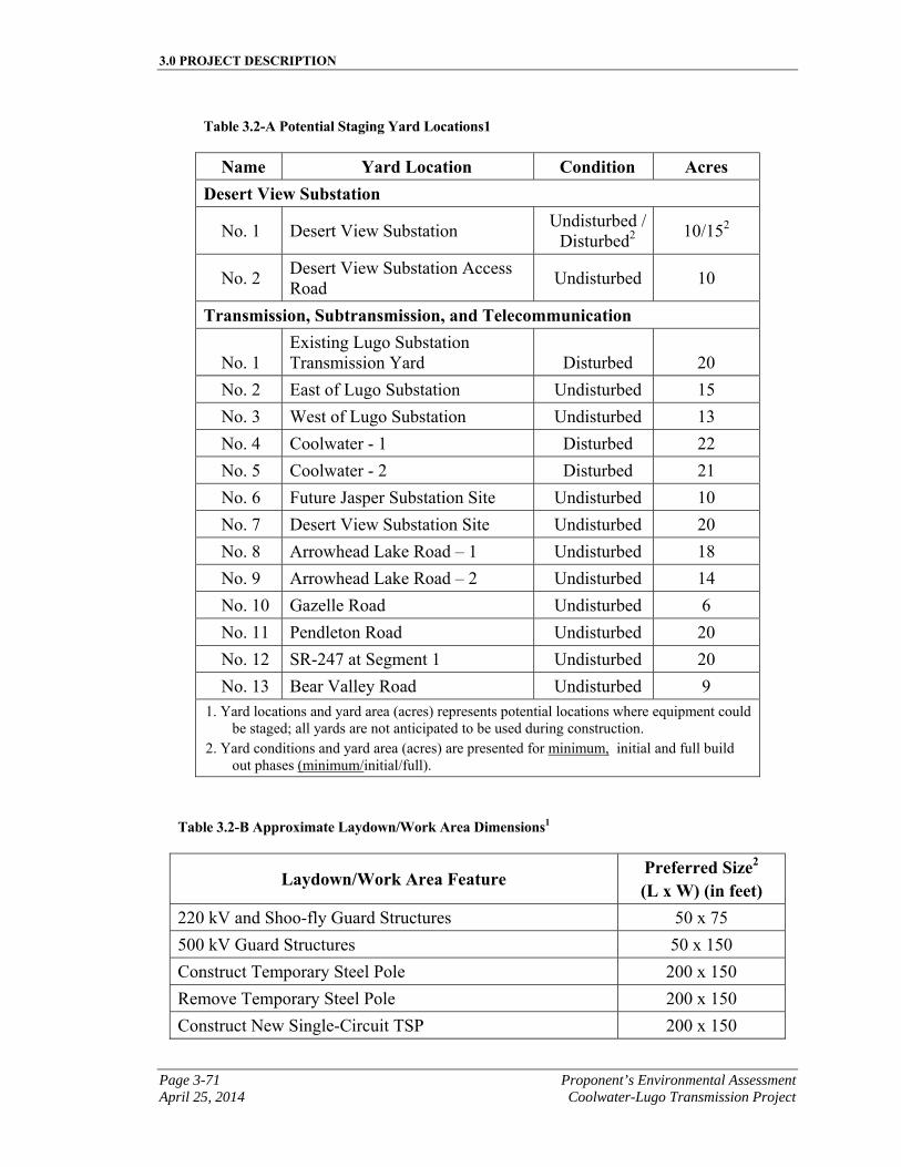
3.0 PROJECT DESCRIPTION
Page 3-71 Proponent’s Environmental Assessment April 25, 2014 Coolwater-Lugo Transmission Project
Table 3.2-A Potential Staging Yard Locations1
Name Yard Location Condition Acres Desert View Substation
No. 1 Desert View Substation Undisturbed /
Disturbed2 10/152
No. 2 Desert View Substation Access Road
Undisturbed 10
Transmission, Subtransmission, and Telecommunication
No. 1 Existing Lugo Substation Transmission Yard Disturbed 20
No. 2 East of Lugo Substation Undisturbed 15
No. 3 West of Lugo Substation Undisturbed 13
No. 4 Coolwater - 1 Disturbed 22
No. 5 Coolwater - 2 Disturbed 21
No. 6 Future Jasper Substation Site Undisturbed 10
No. 7 Desert View Substation Site Undisturbed 20
No. 8 Arrowhead Lake Road – 1 Undisturbed 18
No. 9 Arrowhead Lake Road – 2 Undisturbed 14
No. 10 Gazelle Road Undisturbed 6
No. 11 Pendleton Road Undisturbed 20
No. 12 SR-247 at Segment 1 Undisturbed 20
No. 13 Bear Valley Road Undisturbed 9 1. Yard locations and yard area (acres) represents potential locations where equipment could
be staged; all yards are not anticipated to be used during construction. 2. Yard conditions and yard area (acres) are presented for minimum, initial and full build
out phases (minimum/initial/full).
Table 3.2-B Approximate Laydown/Work Area Dimensions1
Laydown/Work Area Feature Preferred Size2 (L x W) (in feet)
220 kV and Shoo-fly Guard Structures 50 x 75
500 kV Guard Structures 50 x 150
Construct Temporary Steel Pole 200 x 150
Remove Temporary Steel Pole 200 x 150
Construct New Single-Circuit TSP 200 x 150
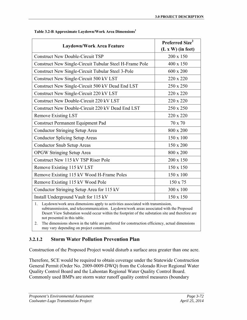
3.0 PROJECT DESCRIPTION
Proponent’s Environmental Assessment Page 3-72 Coolwater-Lugo Transmission Project April 25, 2014
Table 3.2-B Approximate Laydown/Work Area Dimensions1
Laydown/Work Area Feature Preferred Size2 (L x W) (in feet)
Construct New Double-Circuit TSP 200 x 150
Construct New Single-Circuit Tubular Steel H-Frame Pole 400 x 150
Construct New Single-Circuit Tubular Steel 3-Pole 600 x 200
Construct New Single-Circuit 500 kV LST 220 x 220
Construct New Single-Circuit 500 kV Dead End LST 250 x 250
Construct New Single-Circuit 220 kV LST 220 x 220
Construct New Double-Circuit 220 kV LST 220 x 220
Construct New Double-Circuit 220 kV Dead End LST 250 x 250
Remove Existing LST 220 x 220
Construct Permanent Equipment Pad 70 x 70
Conductor Stringing Setup Area 800 x 200
Conductor Splicing Setup Areas 150 x 100
Conductor Snub Setup Areas 150 x 200
OPGW Stringing Setup Area 800 x 200
Construct New 115 kV TSP Riser Pole 200 x 150
Remove Existing 115 kV LST 150 x 150
Remove Existing 115 kV Wood H-Frame Poles 150 x 100
Remove Existing 115 kV Wood Pole 150 x 75
Conductor Stringing Setup Area for 115 kV 300 x 100
Install Underground Vault for 115 kV 150 x 150 1. Laydown/work area dimensions apply to activities associated with transmission,
subtransmission, and telecommunication. Laydown/work areas associated with the Proposed Desert View Substation would occur within the footprint of the substation site and therefore are not presented in this table.
2. The dimensions shown in the table are preferred for construction efficiency, actual dimensions may vary depending on project constraints.
3.2.1.2 Storm Water Pollution Prevention Plan
Construction of the Proposed Project would disturb a surface area greater than one acre.
Therefore, SCE would be required to obtain coverage under the Statewide Construction General Permit (Order No. 2009-0009-DWQ) from the Colorado River Regional Water Quality Control Board and the Lahontan Regional Water Quality Control Board. Commonly used BMPs are storm water runoff quality control measures (boundary
3.0 PROJECT DESCRIPTION
Page 3-73 Proponent’s Environmental Assessment April 25, 2014 Coolwater-Lugo Transmission Project
protection), dewatering procedures, and concrete waste management. The SWPPP(s) would be based on final engineering design and would include all project components.
3.2.1.3 Dust Control
During construction, migration of fugitive dust from the construction sites would be limited by control measures set forth by the MDAQMD. These measures may include the use of water trucks and other dust control measures.
3.2.1.4 Traffic Control
Construction activities completed within public street rights-of-way would require the use of a traffic control service, and all lane closures would be conducted in accordance with any required permit conditions. These traffic control measures would be consistent with those published in the CJUTCM Manual California Joint Utility Traffic Control Manual. (California Inter-Utility Coordinating Committee 2010).
3.2.1.5 FAA Notifications
Based on the current level of project design, SCE anticipates that the alignment of the lines and terrain in the region would require FAA notification due to the height above ground of the conductor or telecommunication cable between towers. SCE has filed documentation for the Proposed Project with the Federal Aviation Administration (“FAA”) for the portions of the project in proximity to area airports (Hesperia Airport, Rabbit Ranch Airfield, and Daggett Airport). FAA response is incomplete at the time this PEA was being prepared. Pending FAA determinations, SCE would work to address potential recommendations if needed into the Proposed Project design during the final engineering phase of the project. As of the time of the preparation of this PEA, SCE anticipates that over the entire length of the Proposed Project approximately 65 structures would require FAA notification (8 structures in Segment 1, 29 structures in Segment 6, 17 structures in Segment 7, 3 structures in Segment 7 Shoofly, 2 structures in Segment 11, and 6 structures in Segment 12). The number of structures requiring FAA notifications would be updated following completion of final engineering.
In accordance with FAA procedures, in advance of construction of any structures in proximity to Hesperia Airport (Alternative Segment 6 and Proposed Segment 7), Barstow-Daggett Airport (Proposed and Alternative Segment 12, Gale to Pisgah Telecommunication Route), and/or Rabbit Ranch Airport (Proposed and Alternative Segment 5), SCE would submit electronic notifications based on final engineering for any new or relocated transmission, subtransmission, and telecommunication structures within 20,000 feet of Hesperia Airport, Rabbit Ranch Airfield, and Daggett Airport. SCE would file the necessary FAA Form 7460 for structures or lines as outlined in Federal Aviation Regulations ("FAR") Part 77. Once SCE files the form with the FAA, the FAA will make recommendations on whether to mark or light portions of the proposed facilities. If a span requires three or fewer marker balls, then the marker balls on the span would all be aviation orange. If a span requires more than three marker balls, then the marker balls would alternate between aviation orange, white, and yellow. Marker balls
3.0 PROJECT DESCRIPTION
Proponent’s Environmental Assessment Page 3-74 Coolwater-Lugo Transmission Project April 25, 2014
would be 36 inches in diameter. If a tower requires lighting, three red lights would be installed, one red “flashing” light at the peak/top and two red “steady” lights at the middle height of the tower. As of the time of the preparation of this PEA, SCE anticipates that the FAA may determine that marker balls should be installed on approximately 8 spans (Segment 6) and lighting might be required on approximately 17 towers (Segments 6 and 7). However, the FAA has not at this time made such a determination as to whether marking or lighting would be recommended for the 220 kV and/or 500 kV transmission line route spans/structures.
3.2.2 Desert View Substation Construction
The following section describes the construction activities associated with installing the components of Desert View Substation for the Proposed Project.
3.2.2.1 Site Preparation and Grading
Minimum Build Out
As part of the minimum build out, the site would be prepared by clearing the existing vegetation within the boundaries of the minimum build out scenario. Once vegetation clearance is completed, the site would be graded in accordance with approved grading plans and a chain link fence would be installed around the boundary. No provisions are made in the minimum build out scenario for future expansion. If the switchyard is expanded, substatntial grading work would be necessary.
Initial or Full Build Out
As part of the initial build out, the entire substation site would be prepared by clearing existing vegetation within the boundaries of the Proposed Desert View Substation site. Once vegetation clearance is completed, the entire site would be graded in accordance with approved grading plans and a temporary chain link fence may be installed around the substation property boundary prior to and/or during construction of the prefabricated concrete panel substation wall and substation components. As presented in Table 3.1-B, Substation Cut and Fill Grading Summary, during full build out, approximately 1.6 million CY of material would be disturbed during site grading and approximately 1.5 million CY of material would be used for onsite fill. Approximately 100,000 CY of material would be removed from the substation site for offsite use or disposal. Full build out of the substation is not anticipated to require additional grading beyond the grading conducted for initial build-out.
3.2.2.2 Below-Grade Construction
For minimum and initial build out scenarios, after the substation site is graded, below-grade facilities would be installed. Below-grade facilities include, for example, a ground grid, cable trenches, equipment foundations, substation perimeter wall foundations, conduit duct banks, and underground structures, such as manholes and vaults.
3.0 PROJECT DESCRIPTION
Page 3-75 Proponent’s Environmental Assessment April 25, 2014 Coolwater-Lugo Transmission Project
At full build out of the Proposed Desert View Substation, additional below-grade facilities would include but not be limited to, a basement for the Control Building, and additional foundations, trenches, conduit, and ground grid associated with construction and operation of the full build out components. This assumes that the initial build out is complete. No provisions have been made to expand to full build out substation from the minimum build out scenario.
3.2.2.3 Above-Grade Construction
ForAt minimum and initial build out scenarios, the above-grade installation of substation facilities such as buses, switchracks and associated electrical equipment, disconnect switches, circuit breakers, transformers, steel support structures, transmission poles, perimeter wall, and the 220 kV MEER would commence after the below-grade structures are in place. The transformers associated with initial build out would not require delivery by heavy-transport vehicles.
At full build out, the above-grade installation of substation facilities would include buses, capacitor banks, switchracks and associated electrical equipment, disconnect switches, circuit breakers, transformers, steel support structures, a Control Building and associated Test & Maintenance Building, as well as a new 115 kV MEER and a 12 kV MEER. The transformers associated with full build out would be delivered by heavy-transport vehicles and installed on the transformer foundation. If necessary, traffic control would be performed as described in Section 3.2.1.4, Traffic Control.
3.2.2.4 Substation Land Disturbance
Table 3.2-C, Substation Estimated Land Disturbance provides a summary of the land disturbance estimates associated with the minmum, initial, and full build out of the Proposed Desert View Substation. The figures in the table are inclusive of any telecom, distribution, subtransmission, and transmission poles within the substation property. Disturbance associated with the external access road to the substation is shown in a separate row within the table.
3.2.2.5 Substation Construction Equipment and Workforce Estimates
The estimated elements, materials and number of personnel and equipment required for construction of the Proposed Desert View Substation at minimum and initial build out are summarized in Table 3.2-D, Substation Construction Equipment and Workforce Estimates (Minimum and Initial Build Out).
Construction would be performed by either SCE crews or contractors. Contractor construction personnel would be managed by SCE construction management personnel. SCE anticipates a total of approximately 15 to 75 construction personnel working on any given day, during minimum, initial or full build out-related construction work. SCE anticipates that crews would work concurrently whenever possible; however, the estimated deployment and number of crew members would be dependent upon local jurisdiction permitting, material availability, and construction scheduling.
3.0 PROJECT DESCRIPTION
Proponent’s Environmental Assessment Page 3-76 Coolwater-Lugo Transmission Project April 25, 2014
In general, construction efforts would occur in accordance with accepted construction industry standards.
The estimated elements, materials and number of personnel and equipment required for construction of the Proposed Desert View Substation at full build out are summarized in Table 3.2-E, Substation Construction Equipment and Workforce Estimates (Full Build Out). Construction equipment and workforce estimates presented in Table 3.2-E, Substation Construction Equipment and Workforce Estimates (Full Build Out), represent the remaining or incremental increase in activities, compared to initial build out, needed to construct future build out components associated with full build out.
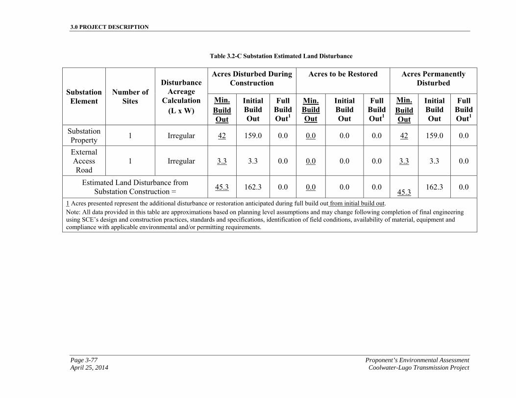
3.0 PROJECT DESCRIPTION
Page 3-77 Proponent’s Environmental Assessment April 25, 2014 Coolwater-Lugo Transmission Project
Table 3.2-C Substation Estimated Land Disturbance
Substation Element
Number of Sites
Disturbance Acreage
Calculation (L x W)
Acres Disturbed During Construction
Acres to be Restored Acres Permanently Disturbed
Min. Build Out
Initial Build Out
Full Build Out1
Min. Build Out
Initial Build Out
Full Build Out1
Min. Build Out
Initial Build Out
Full Build Out1
Substation Property
1 Irregular 42 159.0 0.0 0.0 0.0 0.0 42 159.0 0.0
External Access Road
1 Irregular 3.3 3.3 0.0 0.0 0.0 0.0 3.3 3.3 0.0
Estimated Land Disturbance from Substation Construction =
45.3 162.3 0.0 0.0 0.0 0.0 45.3
162.3 0.0
1 Acres presented represent the additional disturbance or restoration anticipated during full build out from initial build out. Note: All data provided in this table are approximations based on planning level assumptions and may change following completion of final engineering using SCE’s design and construction practices, standards and specifications, identification of field conditions, availability of material, equipment and compliance with applicable environmental and/or permitting requirements.
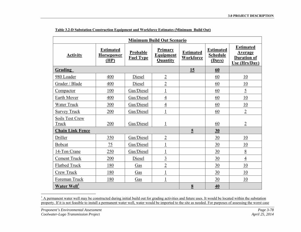
3.0 PROJECT DESCRIPTION
Proponent’s Environmental Assessment Page 3-78 Coolwater-Lugo Transmission Project April 25, 2014
Table 3.2-D Substation Construction Equipment and Workforce Estimates (Minimum Build Out)
Minimum Build Out Scenario
Activity Estimated
Horsepower (HP)
Probable Fuel Type
Primary Equipment Quantity
Estimated Workforce
Estimated Schedule
(Days)
Estimated Average
Duration of Use (Hrs/Day)
Grading 15 60 980 Loader 400 Diesel 2 60 10
Grader / Blade 400 Diesel 2 60 10
Compactor 100 Gas/Diesel 1 60 5
Earth Mover 400 Gas/Diesel 4 60 10
Water Truck 300 Gas/Diesel 4 60 10
Survey Truck 200 Gas/Diesel 1 60 2
Soils Test Crew Truck 200 Gas/Diesel 1
60 2
Chain Link Fence 5 30 Driller 350 Gas/Diesel 2 30 10
Bobcat 75 Gas/Diesel 1 30 10
14-Ton Crane 250 Gas/Diesel 1 30 8
Cement Truck 200 Diesel 3 30 4
Flatbed Truck 180 Gas 2 30 10
Crew Truck 180 Gas 1 30 10
Foreman Truck 180 Gas 1 30 10
Water Well1 8 40
1 A permanent water well may be constructed during initial build out for grading activities and future uses. It would be located within the substation property. If it is not feasible to install a permanent water well, water would be imported to the site as needed. For purposes of assessing the worst case
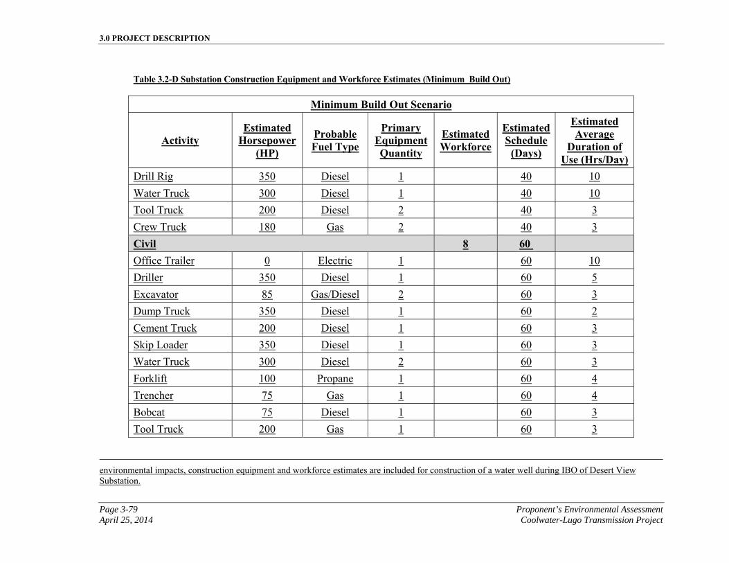
3.0 PROJECT DESCRIPTION
Page 3-79 Proponent’s Environmental Assessment April 25, 2014 Coolwater-Lugo Transmission Project
Table 3.2-D Substation Construction Equipment and Workforce Estimates (Minimum Build Out)
Minimum Build Out Scenario
Activity Estimated
Horsepower (HP)
Probable Fuel Type
Primary Equipment Quantity
Estimated Workforce
Estimated Schedule
(Days)
Estimated Average
Duration of Use (Hrs/Day)
Drill Rig 350 Diesel 1 40 10
Water Truck 300 Diesel 1 40 10
Tool Truck 200 Diesel 2 40 3
Crew Truck 180 Gas 2 40 3
Civil 8 60 Office Trailer 0 Electric 1 60 10
Driller 350 Diesel 1 60 5
Excavator 85 Gas/Diesel 2 60 3
Dump Truck 350 Diesel 1 60 2
Cement Truck 200 Diesel 1 60 3
Skip Loader 350 Diesel 1 60 3
Water Truck 300 Diesel 2 60 3
Forklift 100 Propane 1 60 4
Trencher 75 Gas 1 60 4
Bobcat 75 Diesel 1 60 3
Tool Truck 200 Gas 1 60 3
environmental impacts, construction equipment and workforce estimates are included for construction of a water well during IBO of Desert View Substation.
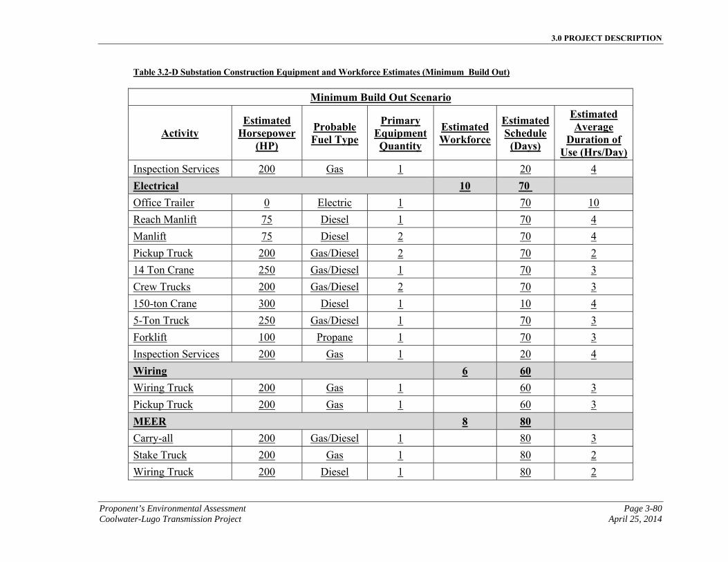
3.0 PROJECT DESCRIPTION
Proponent’s Environmental Assessment Page 3-80 Coolwater-Lugo Transmission Project April 25, 2014
Table 3.2-D Substation Construction Equipment and Workforce Estimates (Minimum Build Out)
Minimum Build Out Scenario
Activity Estimated
Horsepower (HP)
Probable Fuel Type
Primary Equipment Quantity
Estimated Workforce
Estimated Schedule
(Days)
Estimated Average
Duration of Use (Hrs/Day)
Inspection Services 200 Gas 1 20 4
Electrical 10 70 Office Trailer 0 Electric 1 70 10
Reach Manlift 75 Diesel 1 70 4
Manlift 75 Diesel 2 70 4
Pickup Truck 200 Gas/Diesel 2 70 2
14 Ton Crane 250 Gas/Diesel 1 70 3
Crew Trucks 200 Gas/Diesel 2 70 3
150-ton Crane 300 Diesel 1 10 4
5-Ton Truck 250 Gas/Diesel 1 70 3
Forklift 100 Propane 1 70 3
Inspection Services 200 Gas 1 20 4
Wiring 6 60 Wiring Truck 200 Gas 1 60 3
Pickup Truck 200 Gas 1 60 3
MEER 8 80 Carry-all 200 Gas/Diesel 1 80 3
Stake Truck 200 Gas 1 80 2
Wiring Truck 200 Diesel 1 80 2
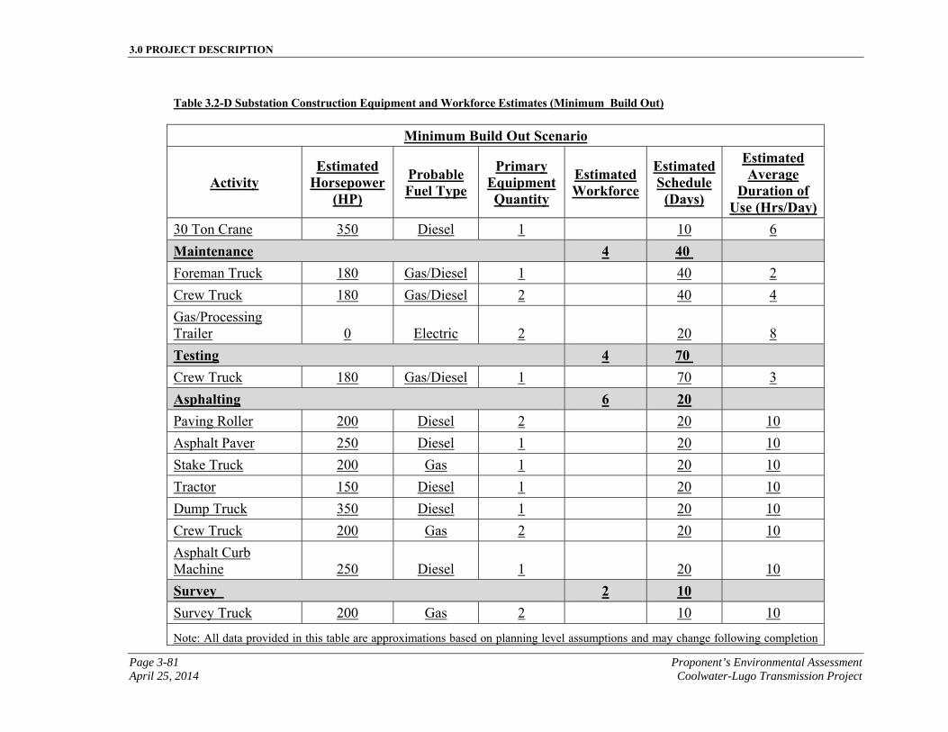
3.0 PROJECT DESCRIPTION
Page 3-81 Proponent’s Environmental Assessment April 25, 2014 Coolwater-Lugo Transmission Project
Table 3.2-D Substation Construction Equipment and Workforce Estimates (Minimum Build Out)
Minimum Build Out Scenario
Activity Estimated
Horsepower (HP)
Probable Fuel Type
Primary Equipment Quantity
Estimated Workforce
Estimated Schedule
(Days)
Estimated Average
Duration of Use (Hrs/Day)
30 Ton Crane 350 Diesel 1 10 6
Maintenance 4 40 Foreman Truck 180 Gas/Diesel 1 40 2
Crew Truck 180 Gas/Diesel 2 40 4
Gas/Processing Trailer 0 Electric 2
20 8
Testing 4 70 Crew Truck 180 Gas/Diesel 1 70 3
Asphalting 6 20 Paving Roller 200 Diesel 2 20 10
Asphalt Paver 250 Diesel 1 20 10
Stake Truck 200 Gas 1 20 10
Tractor 150 Diesel 1 20 10
Dump Truck 350 Diesel 1 20 10
Crew Truck 200 Gas 2 20 10
Asphalt Curb Machine 250 Diesel 1
20 10
Survey 2 10 Survey Truck 200 Gas 2 10 10
Note: All data provided in this table are approximations based on planning level assumptions and may change following completion
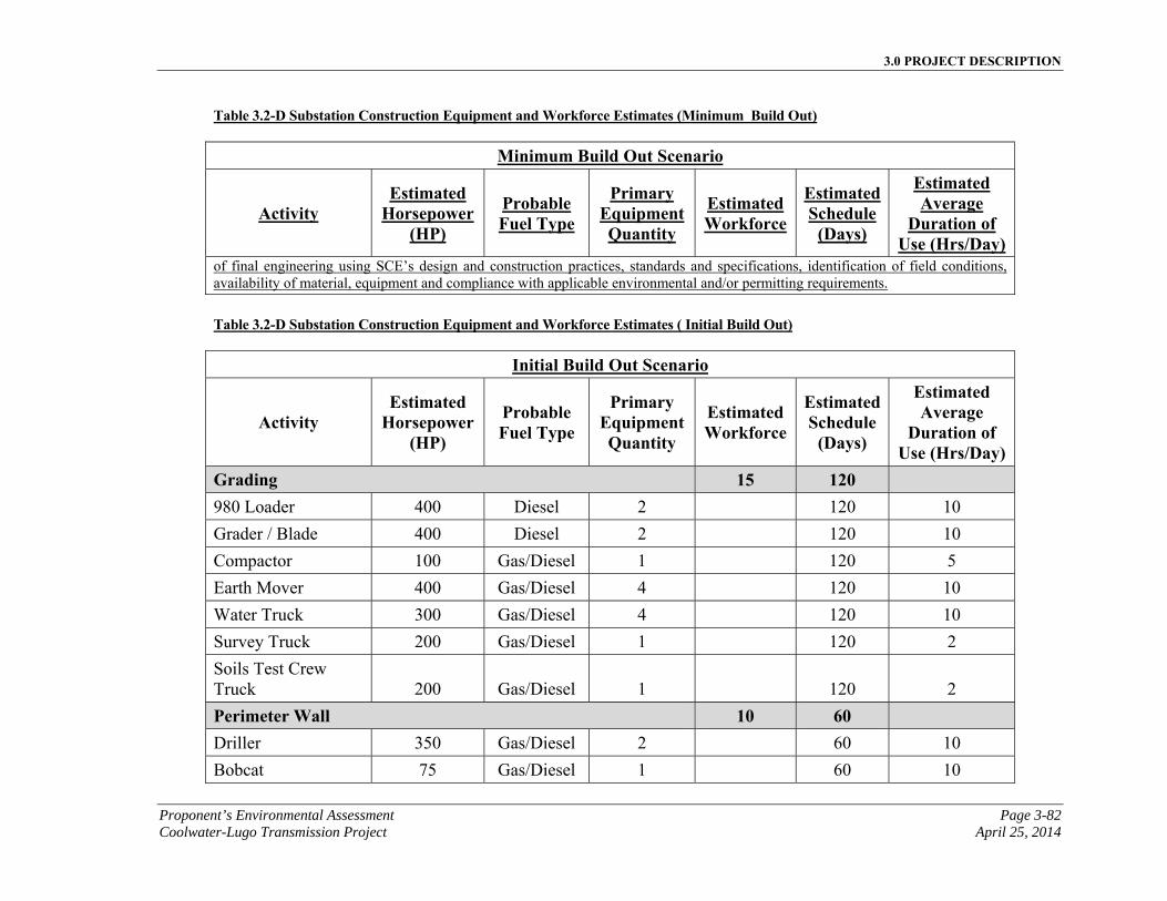
3.0 PROJECT DESCRIPTION
Proponent’s Environmental Assessment Page 3-82 Coolwater-Lugo Transmission Project April 25, 2014
Table 3.2-D Substation Construction Equipment and Workforce Estimates (Minimum Build Out)
Minimum Build Out Scenario
Activity Estimated
Horsepower (HP)
Probable Fuel Type
Primary Equipment Quantity
Estimated Workforce
Estimated Schedule
(Days)
Estimated Average
Duration of Use (Hrs/Day)
of final engineering using SCE’s design and construction practices, standards and specifications, identification of field conditions, availability of material, equipment and compliance with applicable environmental and/or permitting requirements.
Table 3.2-D Substation Construction Equipment and Workforce Estimates ( Initial Build Out)
Initial Build Out Scenario
Activity Estimated
Horsepower (HP)
Probable Fuel Type
Primary Equipment Quantity
Estimated Workforce
Estimated Schedule
(Days)
Estimated Average
Duration of Use (Hrs/Day)
Grading 15 120 980 Loader 400 Diesel 2 120 10
Grader / Blade 400 Diesel 2 120 10
Compactor 100 Gas/Diesel 1 120 5
Earth Mover 400 Gas/Diesel 4 120 10
Water Truck 300 Gas/Diesel 4 120 10
Survey Truck 200 Gas/Diesel 1 120 2
Soils Test Crew Truck 200 Gas/Diesel 1
120 2
Perimeter Wall 10 60 Driller 350 Gas/Diesel 2 60 10
Bobcat 75 Gas/Diesel 1 60 10
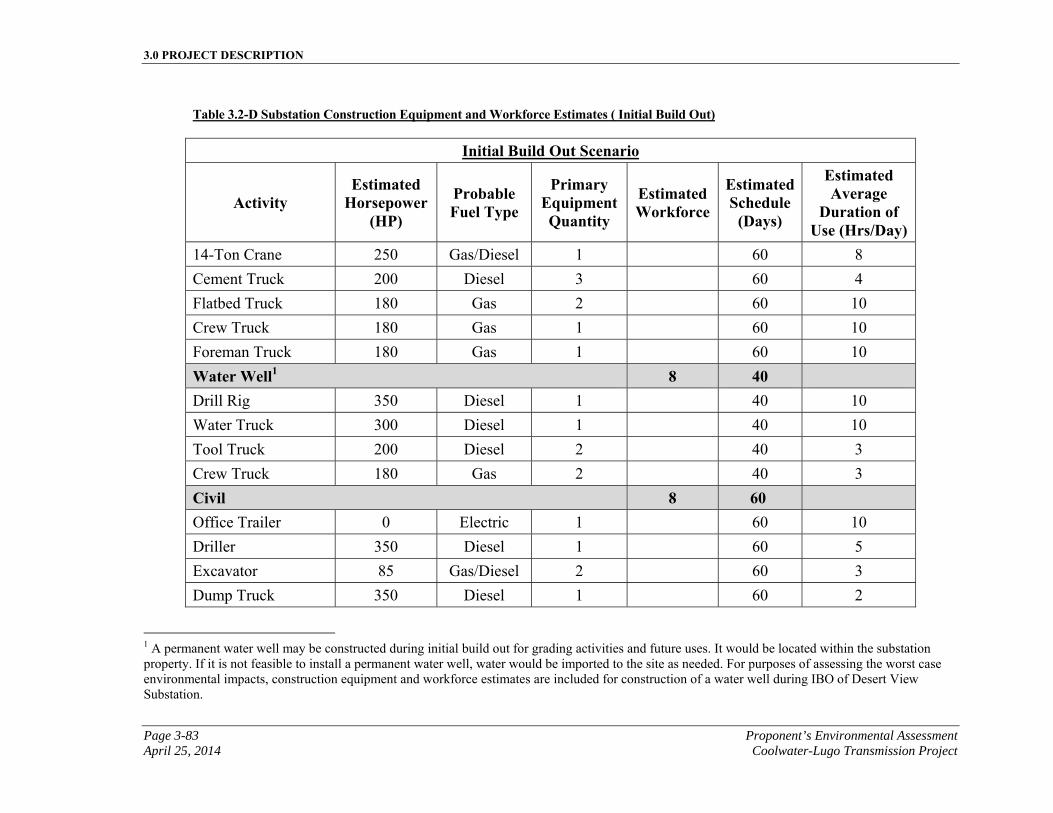
3.0 PROJECT DESCRIPTION
Page 3-83 Proponent’s Environmental Assessment April 25, 2014 Coolwater-Lugo Transmission Project
Table 3.2-D Substation Construction Equipment and Workforce Estimates ( Initial Build Out)
Initial Build Out Scenario
Activity Estimated
Horsepower (HP)
Probable Fuel Type
Primary Equipment Quantity
Estimated Workforce
Estimated Schedule
(Days)
Estimated Average
Duration of Use (Hrs/Day)
14-Ton Crane 250 Gas/Diesel 1 60 8
Cement Truck 200 Diesel 3 60 4
Flatbed Truck 180 Gas 2 60 10
Crew Truck 180 Gas 1 60 10
Foreman Truck 180 Gas 1 60 10
Water Well1 8 40
Drill Rig 350 Diesel 1 40 10
Water Truck 300 Diesel 1 40 10
Tool Truck 200 Diesel 2 40 3
Crew Truck 180 Gas 2 40 3
Civil 8 60 Office Trailer 0 Electric 1 60 10
Driller 350 Diesel 1 60 5
Excavator 85 Gas/Diesel 2 60 3
Dump Truck 350 Diesel 1 60 2
1 A permanent water well may be constructed during initial build out for grading activities and future uses. It would be located within the substation property. If it is not feasible to install a permanent water well, water would be imported to the site as needed. For purposes of assessing the worst case environmental impacts, construction equipment and workforce estimates are included for construction of a water well during IBO of Desert View Substation.
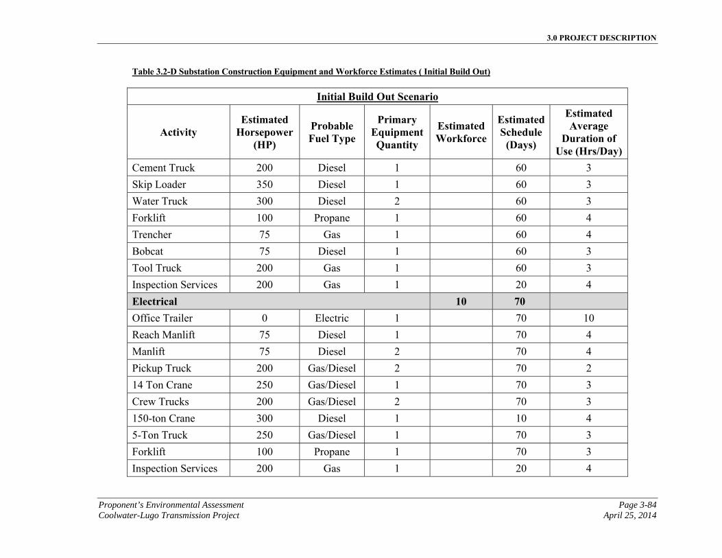
3.0 PROJECT DESCRIPTION
Proponent’s Environmental Assessment Page 3-84 Coolwater-Lugo Transmission Project April 25, 2014
Table 3.2-D Substation Construction Equipment and Workforce Estimates ( Initial Build Out)
Initial Build Out Scenario
Activity Estimated
Horsepower (HP)
Probable Fuel Type
Primary Equipment Quantity
Estimated Workforce
Estimated Schedule
(Days)
Estimated Average
Duration of Use (Hrs/Day)
Cement Truck 200 Diesel 1 60 3
Skip Loader 350 Diesel 1 60 3
Water Truck 300 Diesel 2 60 3
Forklift 100 Propane 1 60 4
Trencher 75 Gas 1 60 4
Bobcat 75 Diesel 1 60 3
Tool Truck 200 Gas 1 60 3
Inspection Services 200 Gas 1 20 4
Electrical 10 70 Office Trailer 0 Electric 1 70 10
Reach Manlift 75 Diesel 1 70 4
Manlift 75 Diesel 2 70 4
Pickup Truck 200 Gas/Diesel 2 70 2
14 Ton Crane 250 Gas/Diesel 1 70 3
Crew Trucks 200 Gas/Diesel 2 70 3
150-ton Crane 300 Diesel 1 10 4
5-Ton Truck 250 Gas/Diesel 1 70 3
Forklift 100 Propane 1 70 3
Inspection Services 200 Gas 1 20 4
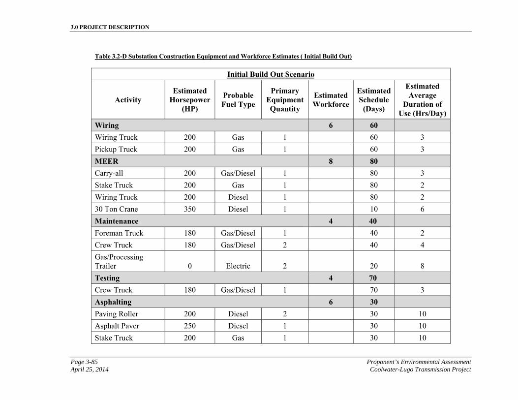
3.0 PROJECT DESCRIPTION
Page 3-85 Proponent’s Environmental Assessment April 25, 2014 Coolwater-Lugo Transmission Project
Table 3.2-D Substation Construction Equipment and Workforce Estimates ( Initial Build Out)
Initial Build Out Scenario
Activity Estimated
Horsepower (HP)
Probable Fuel Type
Primary Equipment Quantity
Estimated Workforce
Estimated Schedule
(Days)
Estimated Average
Duration of Use (Hrs/Day)
Wiring 6 60 Wiring Truck 200 Gas 1 60 3
Pickup Truck 200 Gas 1 60 3
MEER 8 80 Carry-all 200 Gas/Diesel 1 80 3
Stake Truck 200 Gas 1 80 2
Wiring Truck 200 Diesel 1 80 2
30 Ton Crane 350 Diesel 1 10 6
Maintenance 4 40 Foreman Truck 180 Gas/Diesel 1 40 2
Crew Truck 180 Gas/Diesel 2 40 4
Gas/Processing Trailer 0 Electric 2
20 8
Testing 4 70 Crew Truck 180 Gas/Diesel 1 70 3
Asphalting 6 30 Paving Roller 200 Diesel 2 30 10
Asphalt Paver 250 Diesel 1 30 10
Stake Truck 200 Gas 1 30 10
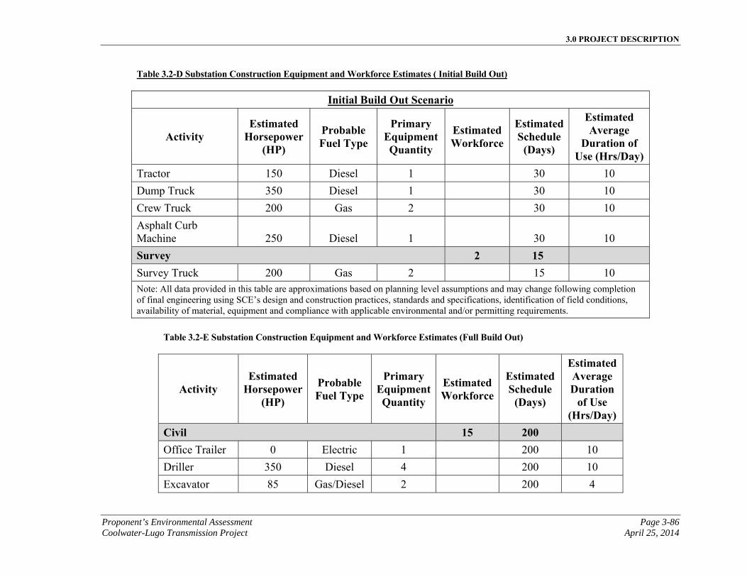
3.0 PROJECT DESCRIPTION
Proponent’s Environmental Assessment Page 3-86 Coolwater-Lugo Transmission Project April 25, 2014
Table 3.2-D Substation Construction Equipment and Workforce Estimates ( Initial Build Out)
Initial Build Out Scenario
Activity Estimated
Horsepower (HP)
Probable Fuel Type
Primary Equipment Quantity
Estimated Workforce
Estimated Schedule
(Days)
Estimated Average
Duration of Use (Hrs/Day)
Tractor 150 Diesel 1 30 10
Dump Truck 350 Diesel 1 30 10
Crew Truck 200 Gas 2 30 10
Asphalt Curb Machine 250 Diesel 1
30 10
Survey 2 15 Survey Truck 200 Gas 2 15 10 Note: All data provided in this table are approximations based on planning level assumptions and may change following completion of final engineering using SCE’s design and construction practices, standards and specifications, identification of field conditions, availability of material, equipment and compliance with applicable environmental and/or permitting requirements.
Table 3.2-E Substation Construction Equipment and Workforce Estimates (Full Build Out)
Activity Estimated
Horsepower (HP)
Probable Fuel Type
Primary Equipment Quantity
Estimated Workforce
Estimated Schedule
(Days)
Estimated Average Duration
of Use (Hrs/Day)
Civil 15 200
Office Trailer 0 Electric 1 200 10
Driller 350 Diesel 4 200 10
Excavator 85 Gas/Diesel 2 200 4
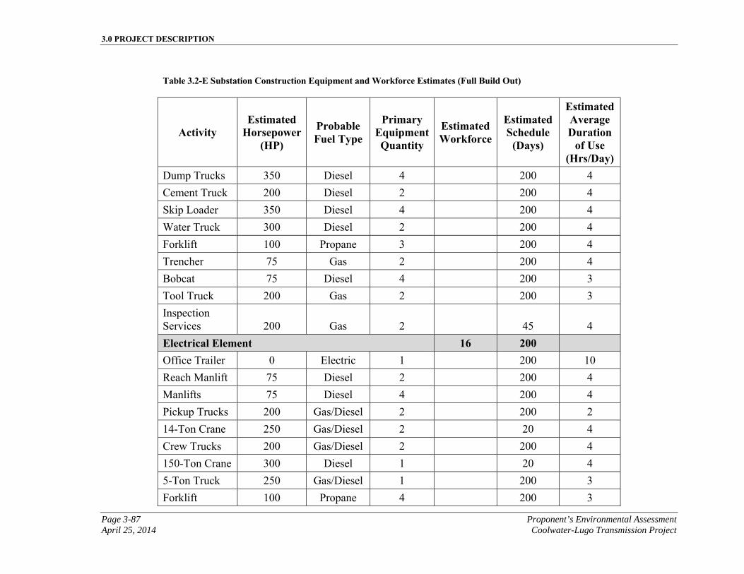
3.0 PROJECT DESCRIPTION
Page 3-87 Proponent’s Environmental Assessment April 25, 2014 Coolwater-Lugo Transmission Project
Table 3.2-E Substation Construction Equipment and Workforce Estimates (Full Build Out)
Activity Estimated
Horsepower (HP)
Probable Fuel Type
Primary Equipment Quantity
Estimated Workforce
Estimated Schedule
(Days)
Estimated Average Duration
of Use (Hrs/Day)
Dump Trucks 350 Diesel 4 200 4
Cement Truck 200 Diesel 2 200 4
Skip Loader 350 Diesel 4 200 4
Water Truck 300 Diesel 2 200 4
Forklift 100 Propane 3 200 4
Trencher 75 Gas 2 200 4
Bobcat 75 Diesel 4 200 3
Tool Truck 200 Gas 2 200 3
Inspection Services 200 Gas 2
45 4
Electrical Element 16 200 Office Trailer 0 Electric 1 200 10
Reach Manlift 75 Diesel 2 200 4
Manlifts 75 Diesel 4 200 4
Pickup Trucks 200 Gas/Diesel 2 200 2
14-Ton Crane 250 Gas/Diesel 2 20 4
Crew Trucks 200 Gas/Diesel 2 200 4
150-Ton Crane 300 Diesel 1 20 4
5-Ton Truck 250 Gas/Diesel 1 200 3
Forklift 100 Propane 4 200 3
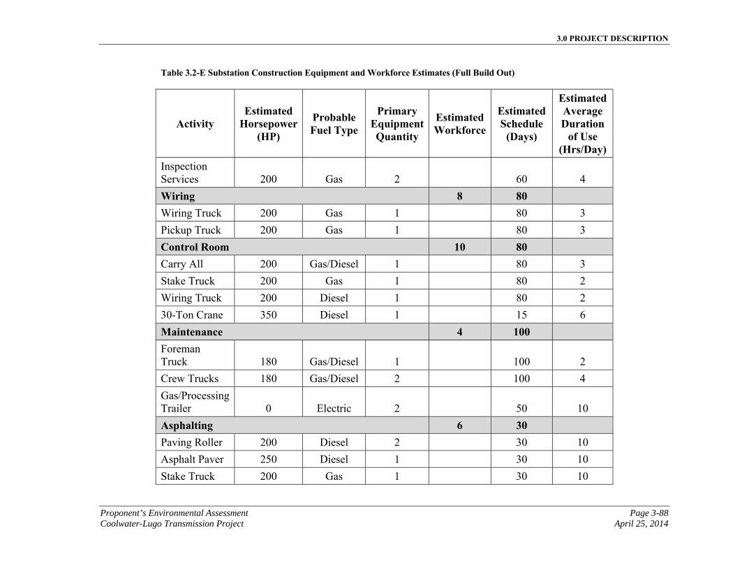
3.0 PROJECT DESCRIPTION
Proponent’s Environmental Assessment Page 3-88 Coolwater-Lugo Transmission Project April 25, 2014
Table 3.2-E Substation Construction Equipment and Workforce Estimates (Full Build Out)
Activity Estimated
Horsepower (HP)
Probable Fuel Type
Primary Equipment Quantity
Estimated Workforce
Estimated Schedule
(Days)
Estimated Average Duration
of Use (Hrs/Day)
Inspection Services 200 Gas 2
60 4
Wiring 8 80
Wiring Truck 200 Gas 1 80 3
Pickup Truck 200 Gas 1 80 3
Control Room 10 80
Carry All 200 Gas/Diesel 1 80 3
Stake Truck 200 Gas 1 80 2
Wiring Truck 200 Diesel 1 80 2
30-Ton Crane 350 Diesel 1 15 6
Maintenance 4 100
Foreman Truck 180 Gas/Diesel 1
100 2
Crew Trucks 180 Gas/Diesel 2 100 4
Gas/Processing Trailer 0 Electric 2
50 10
Asphalting 6 30 Paving Roller 200 Diesel 2 30 10
Asphalt Paver 250 Diesel 1 30 10
Stake Truck 200 Gas 1 30 10
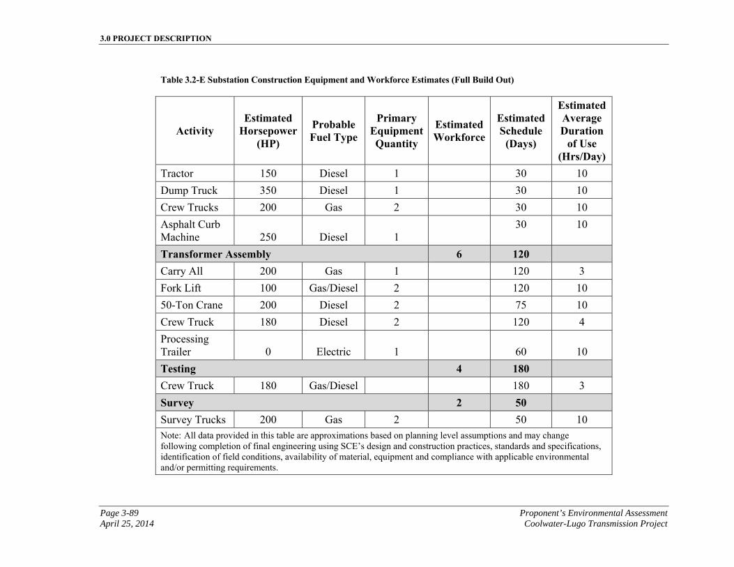
3.0 PROJECT DESCRIPTION
Page 3-89 Proponent’s Environmental Assessment April 25, 2014 Coolwater-Lugo Transmission Project
Table 3.2-E Substation Construction Equipment and Workforce Estimates (Full Build Out)
Activity Estimated
Horsepower (HP)
Probable Fuel Type
Primary Equipment Quantity
Estimated Workforce
Estimated Schedule
(Days)
Estimated Average Duration
of Use (Hrs/Day)
Tractor 150 Diesel 1 30 10
Dump Truck 350 Diesel 1 30 10
Crew Trucks 200 Gas 2 30 10
Asphalt Curb Machine 250 Diesel 1
30 10
Transformer Assembly 6 120 Carry All 200 Gas 1 120 3
Fork Lift 100 Gas/Diesel 2 120 10
50-Ton Crane 200 Diesel 2 75 10
Crew Truck 180 Diesel 2 120 4
Processing Trailer 0 Electric 1
60 10
Testing 4 180
Crew Truck 180 Gas/Diesel 180 3
Survey 2 50 Survey Trucks 200 Gas 2 50 10 Note: All data provided in this table are approximations based on planning level assumptions and may change following completion of final engineering using SCE’s design and construction practices, standards and specifications, identification of field conditions, availability of material, equipment and compliance with applicable environmental and/or permitting requirements.

3.0 PROJECT DESCRIPTION
Proponent’s Environmental Assessment Page 3-90 Coolwater-Lugo Transmission Project April 25, 2014
This page is intentionally blank.
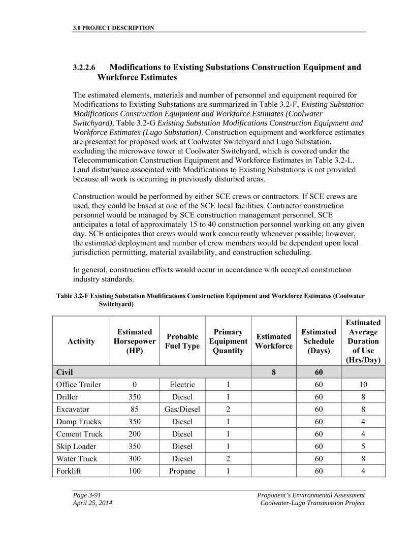
3.0 PROJECT DESCRIPTION
Page 3-91 Proponent’s Environmental Assessment April 25, 2014 Coolwater-Lugo Transmission Project
3.2.2.6 Modifications to Existing Substations Construction Equipment and Workforce Estimates
The estimated elements, materials and number of personnel and equipment required for Modifications to Existing Substations are summarized in Table 3.2-F, Existing Substation Modifications Construction Equipment and Workforce Estimates (Coolwater Switchyard), Table 3.2-G Existing Substation Modifications Construction Equipment and Workforce Estimates (Lugo Substation). Construction equipment and workforce estimates are presented for proposed work at Coolwater Switchyard and Lugo Substation, excluding the microwave tower at Coolwater Switchyard, which is covered under the Telecommunication Construction Equipment and Workforce Estimates in Table 3.2-L. Land disturbance associated with Modifications to Existing Substations is not provided because all work is occurring in previously disturbed areas.
Construction would be performed by either SCE crews or contractors. If SCE crews are used, they could be based at one of the SCE local facilities. Contractor construction personnel would be managed by SCE construction management personnel. SCE anticipates a total of approximately 15 to 40 construction personnel working on any given day. SCE anticipates that crews would work concurrently whenever possible; however, the estimated deployment and number of crew members would be dependent upon local jurisdiction permitting, material availability, and construction scheduling.
In general, construction efforts would occur in accordance with accepted construction industry standards.
Table 3.2-F Existing Substation Modifications Construction Equipment and Workforce Estimates (Coolwater Switchyard)
Activity Estimated
Horsepower (HP)
Probable Fuel Type
Primary Equipment Quantity
Estimated Workforce
Estimated Schedule
(Days)
Estimated Average Duration
of Use (Hrs/Day)
Civil 8 60
Office Trailer 0 Electric 1 60 10
Driller 350 Diesel 1 60 8
Excavator 85 Gas/Diesel 2 60 8
Dump Trucks 350 Diesel 1 60 4
Cement Truck 200 Diesel 1 60 4
Skip Loader 350 Diesel 1 60 5
Water Truck 300 Diesel 2 60 8
Forklift 100 Propane 1 60 4
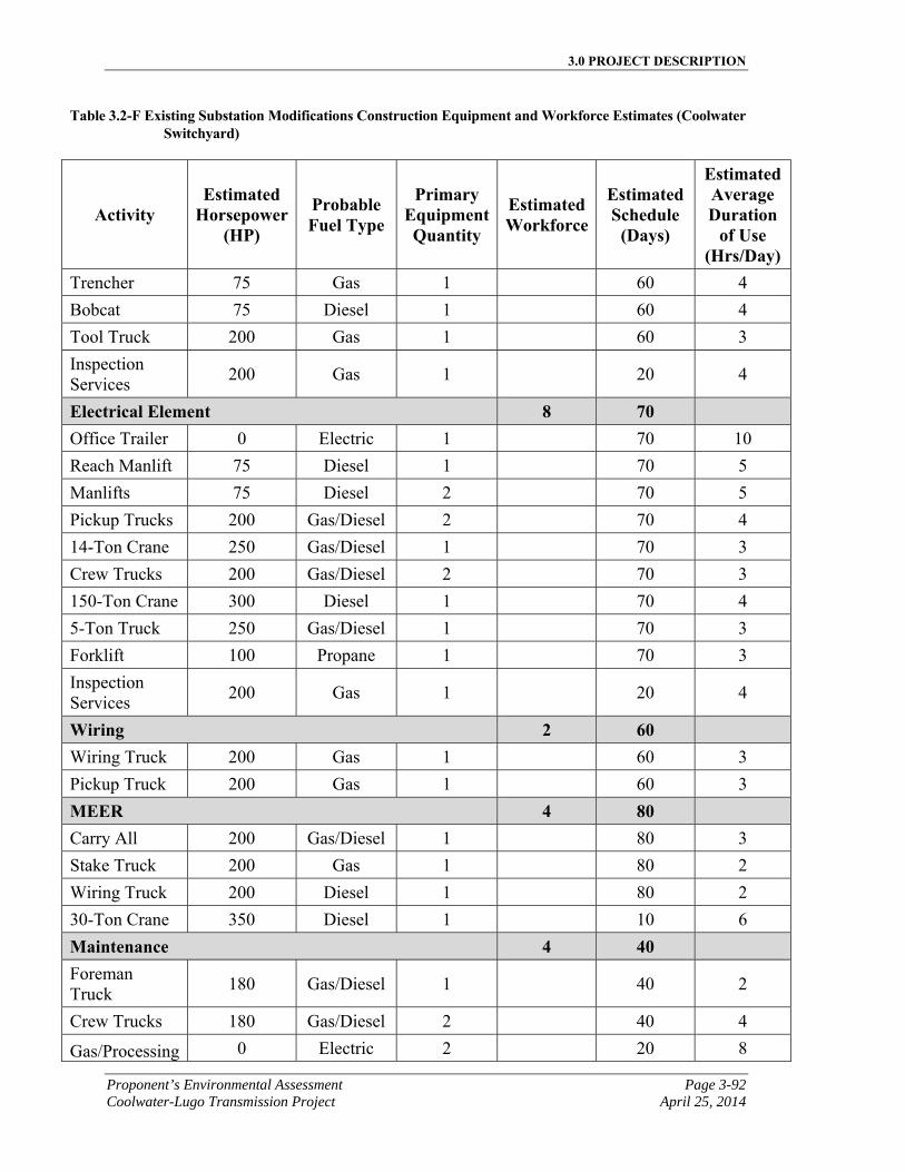
3.0 PROJECT DESCRIPTION
Proponent’s Environmental Assessment Page 3-92 Coolwater-Lugo Transmission Project April 25, 2014
Table 3.2-F Existing Substation Modifications Construction Equipment and Workforce Estimates (Coolwater Switchyard)
Activity Estimated
Horsepower (HP)
Probable Fuel Type
Primary Equipment Quantity
Estimated Workforce
Estimated Schedule
(Days)
Estimated Average Duration
of Use (Hrs/Day)
Trencher 75 Gas 1 60 4
Bobcat 75 Diesel 1 60 4
Tool Truck 200 Gas 1 60 3
Inspection Services
200 Gas 1 20 4
Electrical Element 8 70 Office Trailer 0 Electric 1 70 10
Reach Manlift 75 Diesel 1 70 5
Manlifts 75 Diesel 2 70 5
Pickup Trucks 200 Gas/Diesel 2 70 4
14-Ton Crane 250 Gas/Diesel 1 70 3
Crew Trucks 200 Gas/Diesel 2 70 3
150-Ton Crane 300 Diesel 1 70 4
5-Ton Truck 250 Gas/Diesel 1 70 3
Forklift 100 Propane 1 70 3
Inspection Services
200 Gas 1 20 4
Wiring 2 60
Wiring Truck 200 Gas 1 60 3
Pickup Truck 200 Gas 1 60 3
MEER 4 80
Carry All 200 Gas/Diesel 1 80 3
Stake Truck 200 Gas 1 80 2
Wiring Truck 200 Diesel 1 80 2
30-Ton Crane 350 Diesel 1 10 6
Maintenance 4 40
Foreman Truck
180 Gas/Diesel 1 40 2
Crew Trucks 180 Gas/Diesel 2 40 4
Gas/Processing 0 Electric 2 20 8
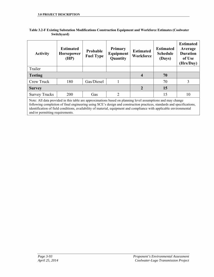
3.0 PROJECT DESCRIPTION
Page 3-93 Proponent’s Environmental Assessment April 25, 2014 Coolwater-Lugo Transmission Project
Table 3.2-F Existing Substation Modifications Construction Equipment and Workforce Estimates (Coolwater Switchyard)
Activity Estimated
Horsepower (HP)
Probable Fuel Type
Primary Equipment Quantity
Estimated Workforce
Estimated Schedule
(Days)
Estimated Average Duration
of Use (Hrs/Day)
Trailer
Testing 4 70
Crew Truck 180 Gas/Diesel 1 70 3
Survey 2 15 Survey Trucks 200 Gas 2 15 10 Note: All data provided in this table are approximations based on planning level assumptions and may change following completion of final engineering using SCE’s design and construction practices, standards and specifications, identification of field conditions, availability of material, equipment and compliance with applicable environmental and/or permitting requirements.
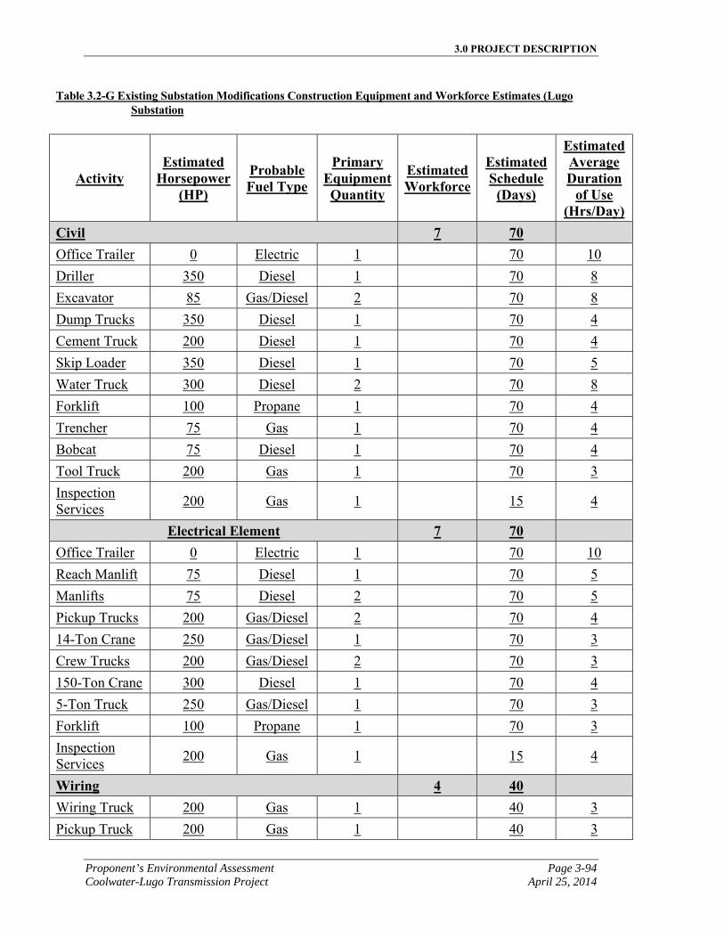
3.0 PROJECT DESCRIPTION
Proponent’s Environmental Assessment Page 3-94 Coolwater-Lugo Transmission Project April 25, 2014
Table 3.2-G Existing Substation Modifications Construction Equipment and Workforce Estimates (Lugo Substation
Activity Estimated
Horsepower (HP)
Probable Fuel Type
Primary Equipment Quantity
Estimated Workforce
Estimated Schedule
(Days)
Estimated Average Duration
of Use (Hrs/Day)
Civil 7 70
Office Trailer 0 Electric 1 70 10
Driller 350 Diesel 1 70 8
Excavator 85 Gas/Diesel 2 70 8
Dump Trucks 350 Diesel 1 70 4
Cement Truck 200 Diesel 1 70 4
Skip Loader 350 Diesel 1 70 5
Water Truck 300 Diesel 2 70 8
Forklift 100 Propane 1 70 4
Trencher 75 Gas 1 70 4
Bobcat 75 Diesel 1 70 4
Tool Truck 200 Gas 1 70 3
Inspection Services
200 Gas 1 15 4
Electrical Element 7 70 Office Trailer 0 Electric 1 70 10
Reach Manlift 75 Diesel 1 70 5
Manlifts 75 Diesel 2 70 5
Pickup Trucks 200 Gas/Diesel 2 70 4
14-Ton Crane 250 Gas/Diesel 1 70 3
Crew Trucks 200 Gas/Diesel 2 70 3
150-Ton Crane 300 Diesel 1 70 4
5-Ton Truck 250 Gas/Diesel 1 70 3
Forklift 100 Propane 1 70 3
Inspection Services
200 Gas 1 15 4
Wiring 4 40
Wiring Truck 200 Gas 1 40 3
Pickup Truck 200 Gas 1 40 3
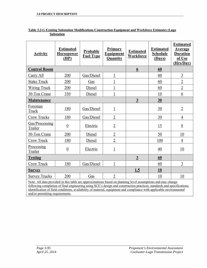
3.0 PROJECT DESCRIPTION
Page 3-95 Proponent’s Environmental Assessment April 25, 2014 Coolwater-Lugo Transmission Project
Table 3.2-G Existing Substation Modifications Construction Equipment and Workforce Estimates (Lugo Substation
Activity Estimated
Horsepower (HP)
Probable Fuel Type
Primary Equipment Quantity
Estimated Workforce
Estimated Schedule
(Days)
Estimated Average Duration
of Use (Hrs/Day)
Control Room 6 60
Carry All 200 Gas/Diesel 1 60 3
Stake Truck 200 Gas 1 60 2
Wiring Truck 200 Diesel 1 60 2
30-Ton Crane 350 Diesel 1 10 6
Maintenance 3 30
Foreman Truck
180 Gas/Diesel 1 30 2
Crew Trucks 180 Gas/Diesel 2 30 4
Gas/Processing Trailer
0 Electric 2 15 8
50-Ton Crane 200 Diesel 2 50 10
Crew Truck 180 Diesel 2 100 4
Processing Trailer
0 Electric 1 40 10
Testing 3 60
Crew Truck 180 Gas/Diesel 1 60 3
Survey 1.5 10 Survey Trucks 200 Gas 2 10 10 Note: All data provided in this table are approximations based on planning level assumptions and may change following completion of final engineering using SCE’s design and construction practices, standards and specifications, identification of field conditions, availability of material, equipment and compliance with applicable environmental and/or permitting requirements.
3.0 PROJECT DESCRIPTION
Proponent’s Environmental Assessment Page 3-96 Coolwater-Lugo Transmission Project April 25, 2014
3.2.3 Transmission Line Installation
The following sections describe the construction activities associated with installing the transmission segments for the Proposed Project.
3.2.3.1 Access and Spur Roads
Where required, a network of existing access roads could be improved and new roads would be constructed to current SCE road practices to support the construction, and operations and maintenance of the Proposed Project.
The typical transmission access road consists of a network of unpaved and paved roads accessed from public and private roads located on public, private, and government lands. These access roads consist of a network of through roads and spur roads which are used to access transmission facilities. Access to the transmission line ROW for construction activities and future operations and maintenance activities associated with the Proposed Project would be accomplished by utilizing this network of roads. The following section describes construction activities typically associated with the construction of these roads.
During construction of the Proposed Project, crews would utilize existing public roads and existing transmission access roads to the maximum extent feasible. New access roads would be constructed to current SCE practices for safety during construction and operations and maintenance. Rehabilitation, road widening, and/or upgrades to existing access roads may also be required to facilitate construction access and to support operation and maintenance activities.
Typical construction activities associated with rehabilitation of existing unpaved access roads include: vegetation clearing, blade-grading, grubbing, mowing, and re-compacting to remove potholes, ruts, and other surface irregularities in order to provide a riding surface capable of supporting heavy construction and maintenance equipment. Existing unpaved roads may also require additional upgrades such as protection (e.g., soil cover, steel plates, etc.) for existing underground utilities.
Typical construction activities associated with new roads generally include similar activities as described for the rehabilitation of existing unpaved roads, but may also include the following additional construction requirements that depend upon the existing land terrain.
▪ Existing relatively flat terrain approximately 0 to 4 percent grade: construction activities are generally similar to rehabilitation activities to existing unpaved roads and in addition may require activities such as clearing and grubbing, and constructing drainage improvements (e.g., wet crossings, water bars, culverts, etc.). Detailed information regarding locations requiring drainage improvements would be provided during final engineering.
3.0 PROJECT DESCRIPTION
Page 3-97 Proponent’s Environmental Assessment April 25, 2014 Coolwater-Lugo Transmission Project
▪ Existing rolling terrain approximately 5 to 12 percent grade: construction activities generally include activities typical to flat terrain and in addition may require activities such as cut and fill in excess of 2 feet in depth, benched grading, drainage improvements (e.g., v-ditches, downdrains, and energy dissipaters, etc.), retaining walls, and slope stability improvements such as geogrid reinforcement. The extent of retaining walls and slope stability improvements would be determined during final engineering, and are described in more detail in Section 3.2.3.2, Retaining Walls. Detailed information regarding locations requiring cut and fill, benched grading and/or drainage improvements would be provided during final engineering.
▪ Existing mountainous terrain over 12 percent grade: construction activities would include similar activities as rolling terrain construction activities and in addition, would likely require significant cut and fill depths, benched grading, drainage improvements and slope stability improvements. Detailed information regarding locations requiring cut and fill, benched grading and/or drainage improvements would be provided during final engineering.
Typical construction activities associated with temporary access could include vegetation clearing, blade-grading, grubbing, mowing, and re-compacting.
In addition to retaining walls, described below in Section 3.2.3.2, Retaining Walls, other slope stability systems considered include mechanically stabilized systems, along with drainage improvements (i.e., v-ditches, downdrains, energy dissipaters, etc.). The extent of slope stability improvements and earth retaining walls would be determined during final engineering. Blasting or fracturing may also be required in some locations and is described further in Section 3.2.3.3, Blasting/Fracturing.
Generally, access roads would have a minimum 14 foot drivable width with 2 feet of shoulder on each side as determined by the existing land terrain to accommodate required drainage features. Typically, the drivable road width would be widened, generally ranging from an additional 0 to 8 feet along curved sections of the access road creating up to 22 feet drivable surface for the access road. Access road gradients would be leveled so that sustained grades generally do not exceed 14 percent. Curves would typically have a minimum radius of curvature of 50 feet measured from the center line of the drivable road width. Specific site locations may require a wider drivable area to accommodate multi-point turns where 50 foot minimum radii cannot be achieved.
Access roads would typically have circle type turnaround areas around the structure location. Where a circle type turnaround is not practical, an alternative turnaround configuration would be constructed to provide safe ingress/egress of vehicles to access the structure location. It is common to use access road turnaround areas for the dual purpose of structure access and as an equipment pad set up area for construction activities. If an equipment pad is built, it would remain as a permanent feature for operations and maintenance.
3.0 PROJECT DESCRIPTION
Proponent’s Environmental Assessment Page 3-98 Coolwater-Lugo Transmission Project April 25, 2014
The Proposed Access Roads generally follow the Proposed Transmission Line Route described in Section 3.1.3, 500 kV and 220 kV Transmission Line Description. The Proposed Road System includes spur roads to individual towers where the access road would need to deviate from the Proposed Transmission Line Route due to terrain considerations and topographic constraints.
Approximately 1.5 miles of new access road would be constructed and existing roads would be improved along the Proposed Transmission Line Segment 12. Access to the Proposed Project would be accomplished by utilizing a network of existing and proposed spur roads and through access roads that would start at the westerly side of existing Coolwater Switchyard and follow the Proposed Transmission Line Route southerly utilizing existing crossings to the north-easterly corner of the intersection of Power Line Road and Camp Rock Road.
Approximately 16.3 miles of new access roads would be constructed and portions of the existing roads would be improved as needed along the Proposed Transmission Line Segment 1. Access to Segment 1 would be accomplished by utilizing a network of existing and proposed spur roads and through access roads that would start at the north-easterly corner of the intersection of Power Line Road and Camp Rock Road, and parallel the network of existing and proposed access roads along Segment 1 southwesterly to the intersection of the LADWP corridor and Stoddard Wells Road.
Approximately 7.2 miles of new access roads would be constructed and portions of existing roads would be improved as needed along the Proposed Transmission Line Segment 2. Access to Segment 2 would be accomplished by utilizing a network of existing and proposed spur roads and through access roads that would start at the intersection of the LADWP corridor and Stoddard Wells Road, continuing southerly to the intersection of Lucerne Valley Cutoff and Stoddard Wells Road. Access roads would meander southeasterly along Lucerne Valley Cutoff to the intersection of SR-247 and Lucerne Valley Cutoff.
Approximately 5.3 miles of new access roads would be constructed and portions of existing roads would be improved as needed along the Proposed Transmission Line Segment 3. Access to the Proposed Project would be accomplished by utilizing a network of existing and proposed spur roads and through access roads that would start at the intersection of SR-247 and Lucerne Valley Cutoff, and continue paralleling the Proposed Transmission Line Route southeasterly to a location approximately 2,800 feet northwest of the intersection of Haynes Road and SR-247.
Approximately 7.9 miles of new access roads would be constructed and portions of existing roads would be improved as needed along the Proposed Transmission Line Segments 5 and 5A. Access to Segments 5 and 5A would be accomplished by utilizing a network of existing and proposed spur roads and through access roads that would start approximately 2,800 feet northwest of the intersection of Haynes Road and SR-247, and would predominately use existing SCE transmission line access roads heading southwesterly across SR-18 and continuing to the Proposed Desert View Substation, located at the northeast corner of Laguna Seca Drive and Desert View Road.
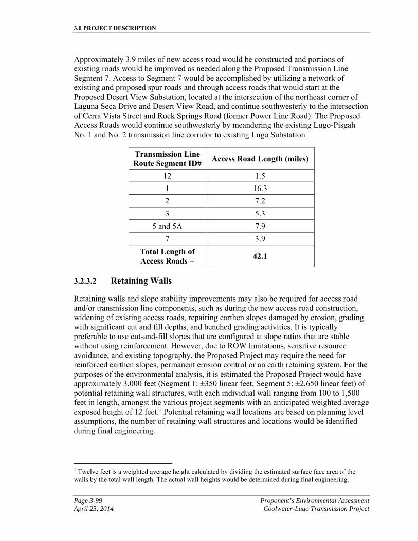
3.0 PROJECT DESCRIPTION
Page 3-99 Proponent’s Environmental Assessment April 25, 2014 Coolwater-Lugo Transmission Project
Approximately 3.9 miles of new access road would be constructed and portions of existing roads would be improved as needed along the Proposed Transmission Line Segment 7. Access to Segment 7 would be accomplished by utilizing a network of existing and proposed spur roads and through access roads that would start at the Proposed Desert View Substation, located at the intersection of the northeast corner of Laguna Seca Drive and Desert View Road, and continue southwesterly to the intersection of Cerra Vista Street and Rock Springs Road (former Power Line Road). The Proposed Access Roads would continue southwesterly by meandering the existing Lugo-Pisgah No. 1 and No. 2 transmission line corridor to existing Lugo Substation.
Transmission Line Route Segment ID# Access Road Length (miles)
12 1.5
1 16.3
2 7.2
3 5.3
5 and 5A 7.9
7 3.9
Total Length of Access Roads = 42.1
3.2.3.2 Retaining Walls
Retaining walls and slope stability improvements may also be required for access road and/or transmission line components, such as during the new access road construction, widening of existing access roads, repairing earthen slopes damaged by erosion, grading with significant cut and fill depths, and benched grading activities. It is typically preferable to use cut-and-fill slopes that are configured at slope ratios that are stable without using reinforcement. However, due to ROW limitations, sensitive resource avoidance, and existing topography, the Proposed Project may require the need for reinforced earthen slopes, permanent erosion control or an earth retaining system. For the purposes of the environmental analysis, it is estimated the Proposed Project would have approximately 3,000 feet (Segment 1: ±350 linear feet, Segment 5: ±2,650 linear feet) of potential retaining wall structures, with each individual wall ranging from 100 to 1,500 feet in length, amongst the various project segments with an anticipated weighted average exposed height of 12 feet.1 Potential retaining wall locations are based on planning level assumptions, the number of retaining wall structures and locations would be identified during final engineering.
1 Twelve feet is a weighted average height calculated by dividing the estimated surface face area of the walls by the total wall length. The actual wall heights would be determined during final engineering.
3.0 PROJECT DESCRIPTION
Proponent’s Environmental Assessment Page 3-100 Coolwater-Lugo Transmission Project April 25, 2014
Construction of the retaining wall and wet crossings would commence with the mobilization of equipment and materials to the project site. Rehabilitation of existing road surfaces with a motor grader to improve travel conditions to a specific construction site would occur as necessary throughout the Proposed Project’s duration. Any existing retaining wall may remain in place to protect the integrity of the access road or tower during construction per the engineering design.
Phase one of the new steel wall installation would consist of the drilling of the pier foundation excavations to the specified dimensions. Once a suitable amount of excavations have been completed, the re-bar cages would be placed and followed up with the setting of the structural steel members.
Phase two would require redi-mix concrete deliveries to the site to complete the pier foundations. Pending production and site conditions, phases 1 and 2 could potentially be repeated several times during the duration of the project.
Phase three would consist of the removal of the existing retaining wall for off-site disposal. The contractor would then begin slope restoration and backfill procedures behind the new steel wall.
Depending on potential wet crossing designs, installation of these structures would be done in a similar manner as the retaining walls.
During non-construction hours, the access road would be secured for safe public passage and no open excavations would be left unattended or uncovered. Upon completion of the civil construction, individual project sites would be returned to a condition that is agreed upon with the land owner.
3.2.3.3 Blasting/Fracturing
It is anticipated that for some of the areas described, rocks, boulders, and other hard materials may interfere with grading activities, and may require rock crushing or blasting operations during construction. During site preparation and excavation/foundation work activities, blasting or fracturing may be required in some locations where rock is present. Prior to blasting, distances to any receptors in the area would be assessed to ensure that the blast would be engineered to be safe and effective. Once final engineering is completed for select transmission structures and access roads, potential locations where blasting or fracturing may be required would be identified. If applicable, pre-blast coordination and/or notification would be made to residents, utilities, and others potentially affected by blasting operations. All blasting would be conducted in accordance with applicable laws and regulatory requirements, including but not limited to OSHA requirements, and all applicable permits from local agencies would be obtained prior to blasting activities.
3.0 PROJECT DESCRIPTION
Page 3-101 Proponent’s Environmental Assessment April 25, 2014 Coolwater-Lugo Transmission Project
3.2.3.4 Structure Site Preparation
The new structure pad locations and laydown/work areas (Table 3.2-B, Approximate Laydown/Work Area Dimensions) would first be graded and/or cleared of vegetation as required to provide a reasonably level and vegetation-free surface for structure installation. Sites would be graded such that water would run toward the direction of the natural drainage. In addition, drainage would be designed to prevent ponding and erosive water flows that could cause damage to the structure footings. The graded area would be compacted to at least 90 percent relative density, and would be capable of supporting heavy vehicular traffic.
Erection of the structures may also require establishment of a permanent equipment pad. The equipment pad would occupy an area of approximately 70 feet by 70 feet and be located adjacent to each applicable structure within the laydown/work area used for structure assembly. The pad may be cleared of vegetation and/or graded as necessary to provide a level surface for equipment operation. The decision to use a separate equipment pad would be determined during final engineering for the Proposed Project and the selection of the appropriate construction methods to be used by SCE or its Contractor.
Benching may be required to provide access for footing construction, assembly, erection, and wire stringing activities during line construction. Benching is a technique in which an earth moving vehicle excavates a terraced access to structure locations in extremely steep and rugged terrain. Benching would also be used on an as-needed basis in areas to help ensure the safety of personnel during construction activities.
Structure foundations would be engineered to satisfy the soil/rock profile at each location as needed based on final engineering results. Typical structure foundations for each LST would consist of four poured-in-place concrete footings, whereas, foundations for each TSP would require a single drilled poured-in-place concrete footing. Actual footing diameters and depths for each of the structure foundations would depend on the soil conditions and topography at each site and would be determined during final engineering.
The foundation process begins with the drilling of the holes for each type of structure. The holes would be drilled using truck or track mounted excavators with various diameter augers to match the diameter requirements of the structure type. LSTs typically require an excavated hole approximately 2.5 feet to 6 feet in diameter at approximately 15 feet to 50 feet deep; TSPs typically require an excavated hole approximately 5 feet to 13 feet in diameter at approximately 15 feet to 50 feet deep. On average, each footing for a LST structure would project approximately 0 to 4 feet above ground level.
The excavated material would be handled as described in Section 3.7, Reusable, Recyclable, and Waste Material Management.
Following excavation of the foundation footings, steel reinforced rebar cages would be set, survey positioning would be verified, and concrete and stub angles (for LSTs only) would then be placed. Steel reinforced rebar cages and stub angles may be assembled at staging yards and delivered to each structure location by flatbed truck or assembled at the
3.0 PROJECT DESCRIPTION
Proponent’s Environmental Assessment Page 3-102 Coolwater-Lugo Transmission Project April 25, 2014
job site. Depending upon the type of structure being constructed, soil conditions, and topography at each site, LSTs would require approximately 16 to 300 cubic yards of concrete delivered to each structure location and, TSPs would require approximately 11 to 300 cubic yards of concrete delivered to each structure location.
Slight to severe ground caving is anticipated along the Proposed Transmission Route during the drilling of the LST and TSP foundations due to the presence of loose soils or groundwater levels. Water, fluid stabilizers, drilling mud and/or casings would be utilized to control ground caving and to stabilize the sidewalls from sloughing. If fluid stabilizers are utilized, mud slurry would be added in conjunction with the drilling. The concrete for the foundation is then pumped to the bottom of the hole, displacing the mud slurry. Mud slurry brought to the surface is typically collected in a pit adjacent to the foundation and/or vacuumed directly into a truck to be reused or discarded at an off-site disposal facility in accordance with all applicable laws.
Concrete samples would be drawn at time of pour and tested to ensure engineered strengths were achieved. A specified SCE concrete mix takes approximately 20 working days to cure to an engineered strength. This strength is verified by controlled testing of sampled concrete. Once this strength has been achieved, crews would be permitted to commence erection of the structure.
Conventional construction techniques would generally be used as described above for new foundation installation. Alternative foundation installation methods would be used where conventional methods are not practical. In certain cases, equipment and material may be deposited at structure sites using helicopters or by workers on foot, and crews may prepare the foundations using hand labor assisted by hydraulic or pneumatic equipment, or other methods.
During construction, existing and SCE-approved concrete supply facilities would be used where feasible. If concrete supply facilities do not exist in certain areas, a temporary concrete batch plant would be set up in an established material staging yard. Equipment would include a central mixer unit (drum type); three silos for injecting concrete additives, fly ash, and cement; a water tank; portable pumps; a pneumatic injector; and a loader for handling concrete additives not in the silos. Dust emissions would be controlled by watering the area and by sealing the silos and transferring the fine particulates pneumatically between the silos and the mixers.
Prior to drilling for foundations, SCE, or its contractor(s), would contact Underground Service Alert to identify any underground utilities in the construction zone.
3.2.3.5 Lattice Steel Tower Installation
LSTs would be assembled within the construction areas at each tower site. See Table 3.2-B, Approximate Laydown/Work Area Dimensions, for approximate laydown dimensions. Structure assembly begins with the hauling and stacking of steel bundles, per engineering drawing requirements, from a staging yard to each structure location. This activity requires use of several trucks with 40-foot trailers and a rough terrain forklift. After steel
3.0 PROJECT DESCRIPTION
Page 3-103 Proponent’s Environmental Assessment April 25, 2014 Coolwater-Lugo Transmission Project
is delivered and stacked, crews would proceed with assembly of leg extensions, body panels, boxed sections, and the cages/bridges. Assembled sections would be lifted into place with a crane and secured by a combined erection and torquing crew. When the steel work is completed, the construction crew may opt to install insulators and wire rollers (travelers) at this time.
If the LST is located in terrain inaccessible by a crane, where substantial grading would be required for access, or schedule constraints warrant it, it is anticipated that a helicopter may be used for the installation of the structure. The use of helicopters for the erection of structures would be similar to methods detailed in IEEE 951-1996, Guide to the Assembly and Erection of Metal Transmission Structures, Section 9, Helicopter Methods of Construction. See Section 3.2.3.11, Helicopter Use, for detailed information on helicopter usage.
3.2.3.6 Tubular Steel Pole Installation
TSPs consist of multiple sections. The pole sections would be placed in temporary laydown areas at each pole location. See Table 3.2-B, Approximate Laydown/Work Area Dimensions, for approximate laydown dimensions. Depending on conditions at the time of construction, the top sections may come pre-configured, may be configured on the ground, or configured after pole installation with the necessary cross arms, insulators, and wire stringing hardware. A crane would then be used to set each steel pole base section on top of the previously prepared foundations. When the base section is secured, the subsequent section of the TSP would be slipped together into place onto the base section. The pole sections may also be spot welded together for additional stability. Depending on the terrain and available equipment, the pole sections could also be pre-assembled into a complete structure prior to setting the poles.
3.2.3.7 Counterpoise
Transmission structures located within the substation boundary would be grounded to the substation ground grid. Foundations for 220/500 kV structures located more than 700 feet outside a substation would have adequate grounding.
If adequate foundation to ground resistance criteria cannot be met with ground rods, a counterpoise system would be installed. A counterpoise is an additional ground wire installed below ground adjacent to and attached to the structure to increase conductivity between the structure and the ground so that adequate grounding can be achieved.
3.2.3.8 Guard Structures
Guard structures are temporary structures that would typically be installed at transportation, flood control, and utility crossings for wire stringing/removal activities. These structures are designed to stop the movement of a conductor should it momentarily drop below a conventional stringing height. SCE estimates that 460 guard structures may need to be constructed along the Proposed Transmission Route.
3.0 PROJECT DESCRIPTION
Proponent’s Environmental Assessment Page 3-104 Coolwater-Lugo Transmission Project April 25, 2014
Typical guard structures are standard wood poles. Depending on the overall spacing of the conductors being installed, approximately two to four guard poles would be required on either side of a crossing. In some cases, the wood poles could be substituted with the use of specifically equipped boom trucks or, at highway crossings, temporary netting could be installed if required. The guard structures would be removed after the conductor is secured into place.
For highways, roads, railroads, utility crossings, and the California Aqueduct, SCE would work closely with the applicable jurisdiction and permitting agencies to secure the necessary permits to string conductor over the applicable infrastructure.
3.2.3.9 Wire Stringing
Wire stringing activities would be in accordance with SCE common practices and are similar to process methods detailed in the IEEE Standard 524-2003 (Guide to the Installation of Overhead Transmission Line Conductors).
To ensure the safety of workers and the public, safety devices such as traveling grounds, guard structures, radio-equipped public safety roving vehicles and linemen would be in place prior to the initiation of wire stringing activities. Advanced planning by supervision is required to determine circuit outages, pulling times, and safety protocols for ensuring that the safe installation of wire is accomplished. Wire stringing includes all activities associated with the installation of the primary conductors onto transmission line structures. These activities include the installation of conductor, ground wire (“OHGW/OPGW”), insulators, stringing sheaves (rollers or travelers), vibration dampeners, weights, suspension and dead-end hardware assemblies for the entire length of the route.
The following five steps describe typical wire stringing activities:
▪ Step 1: Planning: Develop a wire stringing plan to determine the sequence of wire pulls and the set-up locations for the wire pull/tensioning/splicing equipment.
▪ Step 2: Sock Line Threading: A helicopter would fly a lightweight sock line from structure to structure, which would be threaded through rollers in order to engage a camlock device that would secure the pulling sock in the roller. This threading process would continue between all structures through the rollers of a particular set of spans selected for a wire pull.
▪ Step 3: Pulling: The sock line would be used to pull in the conductor pulling rope and/or cable. The pulling rope or cable would be attached to the conductor using a special swivel joint to prevent damage to the wire and to allow the wire to rotate freely to prevent complications from twisting as the conductor unwinds off the reel.
▪ Step 4: Splicing, Sagging, and Dead-Ending: Once the conductor is pulled in, if necessary, all mid-span splicing would be performed at dead end tower locations. Once the conductor is to proper tension and dead-ended to the structures, the
3.0 PROJECT DESCRIPTION
Page 3-105 Proponent’s Environmental Assessment April 25, 2014 Coolwater-Lugo Transmission Project
splicing would be completed. At the determination of SCE and/or SCE’s construction contractor, implosive sleeves may be used for splicing conductor together.1
▪ Step 5: Clipping-In: After the conductor is dead-ended, the conductors would be secured to all tangent structures; a process called clipping in. Once this is complete, spacers would be attached between the bundled conductors of each phase to keep uniform separation between each conductor. Helicopters may be used during this step to assist with transport of tools, equipment and construction personnel, or for insulator installation.
3.2.3.10 Transmission Wire Pulling and Splicing Locations
The puller, tensioner, and splicing set-up locations associated with the Proposed Transmission Route would be temporary and the land would be restored to its previous condition following completion of pulling and splicing activities. The set-up locations require level areas to allow for maneuvering of the equipment and, when possible, these locations would be located on existing roads and level areas to minimize the need for grading and cleanup. The number and location of these sites would be determined during final engineering. The approximate area needed for stringing set-ups associated with wire installation is variable and depends upon terrain. See Table 3.2-B, Approximate Laydown/Work Area Dimensions, for approximate size of pulling, tensioning and splicing equipment set-up areas and laydown dimensions.
Wire pulls are the length of any given continuous wire installation process between two selected points along the line. Wire pulls are selected based on availability of dead-end structures, conductor size, geometry of the line as affected by points of inflection, terrain, and suitability of stringing and splicing equipment set-up locations. On relatively straight alignments, typical wire pulls occur approximately every 15,000 to 18,000 feet and wire splices every 7,500 to 9,000 feet on flat terrain. When the line route alignment contains multiple deflections or is situated in rugged terrain, the length of the wire pull is diminished. Generally, pulling locations and equipment set-ups would be in direct line with the direction of the overhead conductors and established approximately a distance of three times the height away from the adjacent structure.
Each stringing operation consists of a puller set-up positioned at one end and a tensioner set-up with wire reel stand truck positioned at the other end of the wire pull. Pulling and wire tensioning locations may also be utilized for splicing and field snubbing of the conductors. Temporary splices, if required, are necessary since permanent splices that join the conductor together cannot travel through the rollers. Splicing set-up locations are 1 Implosive splicing involves placing a layer of explosives around an aluminum sleeve. A protective layer of plastic is wrapped around the explosive to keep the entire assembly clean and dry. The layer of explosive is designed with the right properties of detonation velocity, pressure and geometry so that it will create the required compression. Although explosive energy is extremely high, it can be controlled to a high degree of accuracy. In the case of implosive connectors, explosive energy is harnessed in a precisely engineered manner to produce a carefully controlled compression of the sleeve around the conductor.
3.0 PROJECT DESCRIPTION
Proponent’s Environmental Assessment Page 3-106 Coolwater-Lugo Transmission Project April 25, 2014
used to remove temporary pulling splices and install permanent splices once the conductor is strung through the rollers located on each structure. Field snubs (i.e., anchoring and dead-end hardware) would be temporarily installed to sag conductor wire to the correct tension at locations where stringing equipment cannot be positioned in back of a dead-end structure.
3.2.3.11 Helicopter Use
Helicopters could be used to support construction activities in areas where access is limited (e.g., no suitable access road, limited construction area to facilitate on-site structure assembly, and/or there are environmental constraints to accessing the project area with standard construction vehicles and equipment), substantial grading would be required for access, or when schedule or system outage constraints are a factor. Project related helicopter activities would include transportation of construction workers, delivery of equipment and materials to structure sites, structure placement, hardware installation, and conductor or OPGW stringing operations. Helicopters may be used in other areas to facilitate construction dependent upon recommendations by the installation contractor.
The operations area of the helicopters would be limited to the project area including, helicopter staging yards, material yards, ground locations in close proximity to conductor or OPGW pulling, tensioning, and splice sites, including locations in previously disturbed areas near construction sites. Helicopters could fly from local airports or staging areas to work areas or also from work area to work area. In addition, helicopters must be able to land within SCE ROWs, which could include landing on access or spur roads. All helicopter refueling in the staging yards, material yards, ROWs or access or spur roads, would be in accordance with the SWPPP. It is also assumed that at night or on off days, for safety and security concerns, helicopters and their associated support vehicles and equipment may be based at a local airport.
3.2.3.12 Transfer/Removal of Existing Structures/Facilities
The Proposed Transmission Route would involve removing structures, conductor and associated hardware.
Approximately 29.1 miles of SCE’s existing Lugo-Pisgah No. 1 220 kV transmission line from a point approximately 0.45 miles southwest of the intersection of Haynes Road and SR-247 (directly south of the location of future Jasper Substation) to Lugo Substation, and approximately 16.0 miles of SCE’s existing Lugo-Pisgah No. 2 220 kV transmission line from Proposed Desert View Substation to Lugo Substation, would be removed as part of the Proposed Project. Approximately 168 structures would be removed. As described above in Section 3.2.3.11, Helicopter Use, helicopters may be used for the transport of tools, equipment, or construction personnel in support of the transfer/removal of existing structures and facilities.
SCE proposes to remove the above-referenced transmission structures and conductors in the following sequence:
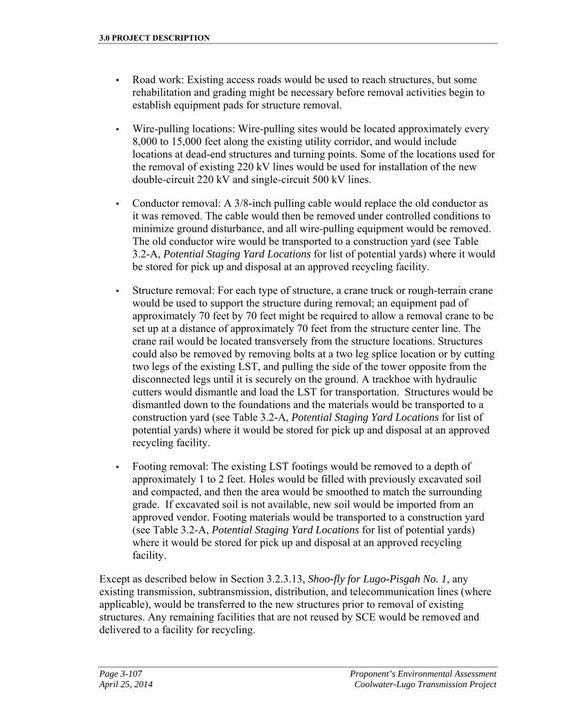
3.0 PROJECT DESCRIPTION
Page 3-107 Proponent’s Environmental Assessment April 25, 2014 Coolwater-Lugo Transmission Project
▪ Road work: Existing access roads would be used to reach structures, but some rehabilitation and grading might be necessary before removal activities begin to establish equipment pads for structure removal.
▪ Wire-pulling locations: Wire-pulling sites would be located approximately every 8,000 to 15,000 feet along the existing utility corridor, and would include locations at dead-end structures and turning points. Some of the locations used for the removal of existing 220 kV lines would be used for installation of the new double-circuit 220 kV and single-circuit 500 kV lines.
▪ Conductor removal: A 3/8-inch pulling cable would replace the old conductor as it was removed. The cable would then be removed under controlled conditions to minimize ground disturbance, and all wire-pulling equipment would be removed. The old conductor wire would be transported to a construction yard (see Table 3.2-A, Potential Staging Yard Locations for list of potential yards) where it would be stored for pick up and disposal at an approved recycling facility.
▪ Structure removal: For each type of structure, a crane truck or rough-terrain crane would be used to support the structure during removal; an equipment pad of approximately 70 feet by 70 feet might be required to allow a removal crane to be set up at a distance of approximately 70 feet from the structure center line. The crane rail would be located transversely from the structure locations. Structures could also be removed by removing bolts at a two leg splice location or by cutting two legs of the existing LST, and pulling the side of the tower opposite from the disconnected legs until it is securely on the ground. A trackhoe with hydraulic cutters would dismantle and load the LST for transportation. Structures would be dismantled down to the foundations and the materials would be transported to a construction yard (see Table 3.2-A, Potential Staging Yard Locations for list of potential yards) where it would be stored for pick up and disposal at an approved recycling facility.
▪ Footing removal: The existing LST footings would be removed to a depth of approximately 1 to 2 feet. Holes would be filled with previously excavated soil and compacted, and then the area would be smoothed to match the surrounding grade. If excavated soil is not available, new soil would be imported from an approved vendor. Footing materials would be transported to a construction yard (see Table 3.2-A, Potential Staging Yard Locations for list of potential yards) where it would be stored for pick up and disposal at an approved recycling facility.
Except as described below in Section 3.2.3.13, Shoo-fly for Lugo-Pisgah No. 1, any existing transmission, subtransmission, distribution, and telecommunication lines (where applicable), would be transferred to the new structures prior to removal of existing structures. Any remaining facilities that are not reused by SCE would be removed and delivered to a facility for recycling.
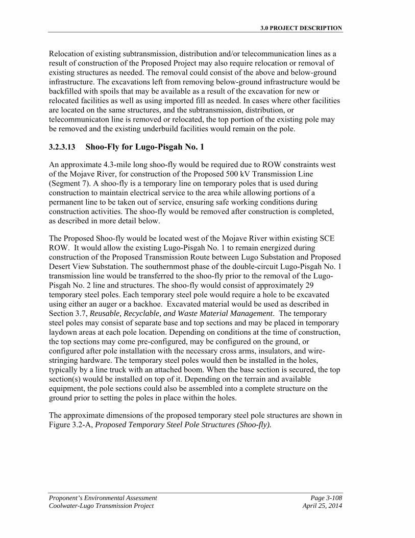
3.0 PROJECT DESCRIPTION
Proponent’s Environmental Assessment Page 3-108 Coolwater-Lugo Transmission Project April 25, 2014
Relocation of existing subtransmission, distribution and/or telecommunication lines as a result of construction of the Proposed Project may also require relocation or removal of existing structures as needed. The removal could consist of the above and below-ground infrastructure. The excavations left from removing below-ground infrastructure would be backfilled with spoils that may be available as a result of the excavation for new or relocated facilities as well as using imported fill as needed. In cases where other facilities are located on the same structures, and the subtransmission, distribution, or telecommunicaton line is removed or relocated, the top portion of the existing pole may be removed and the existing underbuild facilities would remain on the pole.
3.2.3.13 Shoo-Fly for Lugo-Pisgah No. 1
An approximate 4.3-mile long shoo-fly would be required due to ROW constraints west of the Mojave River, for construction of the Proposed 500 kV Transmission Line (Segment 7). A shoo-fly is a temporary line on temporary poles that is used during construction to maintain electrical service to the area while allowing portions of a permanent line to be taken out of service, ensuring safe working conditions during construction activities. The shoo-fly would be removed after construction is completed, as described in more detail below.
The Proposed Shoo-fly would be located west of the Mojave River within existing SCE ROW. It would allow the existing Lugo-Pisgah No. 1 to remain energized during construction of the Proposed Transmission Route between Lugo Substation and Proposed Desert View Substation. The southernmost phase of the double-circuit Lugo-Pisgah No. 1 transmission line would be transferred to the shoo-fly prior to the removal of the Lugo-Pisgah No. 2 line and structures. The shoo-fly would consist of approximately 29 temporary steel poles. Each temporary steel pole would require a hole to be excavated using either an auger or a backhoe. Excavated material would be used as described in Section 3.7, Reusable, Recyclable, and Waste Material Management. The temporary steel poles may consist of separate base and top sections and may be placed in temporary laydown areas at each pole location. Depending on conditions at the time of construction, the top sections may come pre-configured, may be configured on the ground, or configured after pole installation with the necessary cross arms, insulators, and wire-stringing hardware. The temporary steel poles would then be installed in the holes, typically by a line truck with an attached boom. When the base section is secured, the top section(s) would be installed on top of it. Depending on the terrain and available equipment, the pole sections could also be assembled into a complete structure on the ground prior to setting the poles in place within the holes.
The approximate dimensions of the proposed temporary steel pole structures are shown in Figure 3.2-A, Proposed Temporary Steel Pole Structures (Shoo-fly).
3.0 PROJECT DESCRIPTION
Page 3-109 Proponent’s Environmental Assessment April 25, 2014 Coolwater-Lugo Transmission Project
Figure 3.2-A Proposed Temporary Steel Pole Structures (Shoo-fly)
Typical 220 kV SW-DE (Shoo-fly)
3.0 PROJECT DESCRIPTION
Proponent’s Environmental Assessment Page 3-110 Coolwater-Lugo Transmission Project April 25, 2014
Typical 220 kV SW-SUSP (Shoo-fly)
Temporary steel guy stub poles would be installed similarly to temporary steel poles.
The temporary steel poles would be approximately 1.2 to 3.2 feet in diameter at the base and extend approximately 55 feet to 130 feet above ground. The temporary steel poles would be direct embedment type with embedment depths approximately 7.5 feet to 20 feet.
The removal of the approximately 29 temporary steel poles would consist of the above and below-ground portions of the pole. The holes left from removing the poles would be
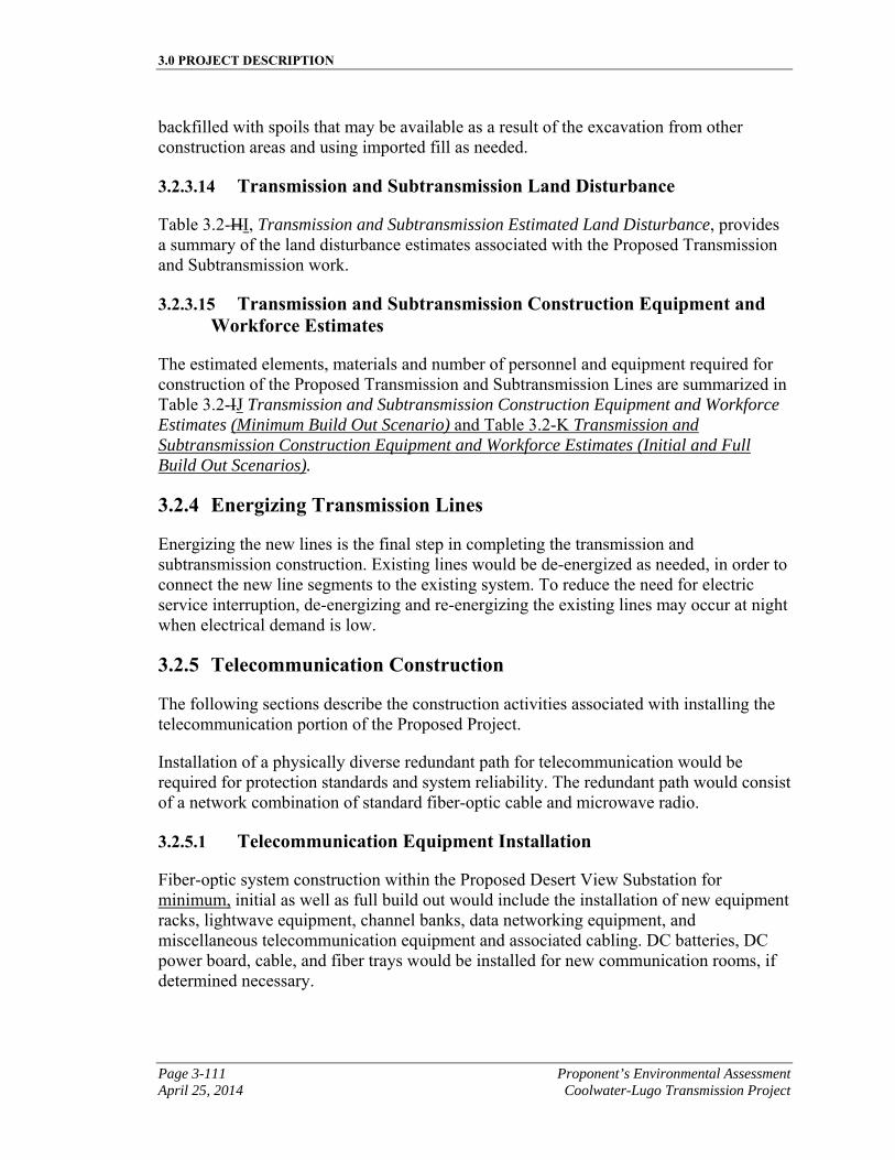
3.0 PROJECT DESCRIPTION
Page 3-111 Proponent’s Environmental Assessment April 25, 2014 Coolwater-Lugo Transmission Project
backfilled with spoils that may be available as a result of the excavation from other construction areas and using imported fill as needed.
3.2.3.14 Transmission and Subtransmission Land Disturbance
Table 3.2-HI, Transmission and Subtransmission Estimated Land Disturbance, provides a summary of the land disturbance estimates associated with the Proposed Transmission and Subtransmission work.
3.2.3.15 Transmission and Subtransmission Construction Equipment and Workforce Estimates
The estimated elements, materials and number of personnel and equipment required for construction of the Proposed Transmission and Subtransmission Lines are summarized in Table 3.2-IJ Transmission and Subtransmission Construction Equipment and Workforce Estimates (Minimum Build Out Scenario) and Table 3.2-K Transmission and Subtransmission Construction Equipment and Workforce Estimates (Initial and Full Build Out Scenarios).
3.2.4 Energizing Transmission Lines
Energizing the new lines is the final step in completing the transmission and subtransmission construction. Existing lines would be de-energized as needed, in order to connect the new line segments to the existing system. To reduce the need for electric service interruption, de-energizing and re-energizing the existing lines may occur at night when electrical demand is low.
3.2.5 Telecommunication Construction
The following sections describe the construction activities associated with installing the telecommunication portion of the Proposed Project.
Installation of a physically diverse redundant path for telecommunication would be required for protection standards and system reliability. The redundant path would consist of a network combination of standard fiber-optic cable and microwave radio.
3.2.5.1 Telecommunication Equipment Installation
Fiber-optic system construction within the Proposed Desert View Substation for minimum, initial as well as full build out would include the installation of new equipment racks, lightwave equipment, channel banks, data networking equipment, and miscellaneous telecommunication equipment and associated cabling. DC batteries, DC power board, cable, and fiber trays would be installed for new communication rooms, if determined necessary.

3.0 PROJECT DESCRIPTION
Proponent’s Environmental Assessment Page 3-112 Coolwater-Lugo Transmission Project April 25, 2014
This page is intentionally blank.
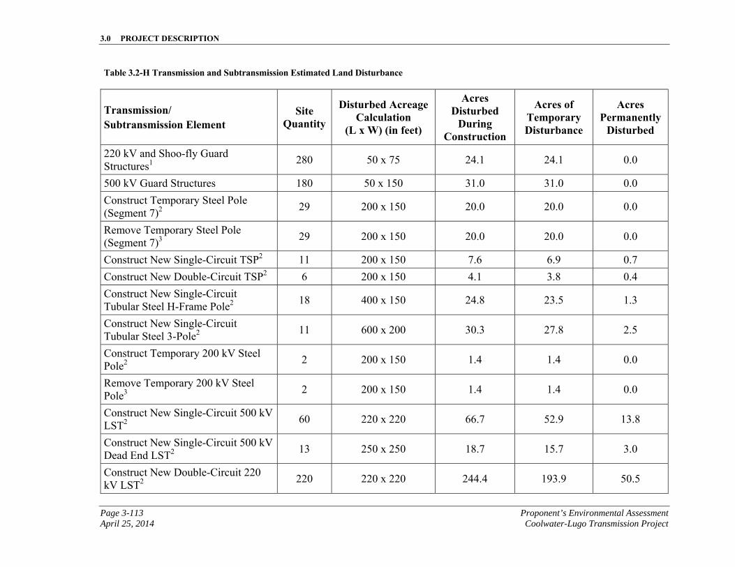
3.0 PROJECT DESCRIPTION
Page 3-113 Proponent’s Environmental Assessment April 25, 2014 Coolwater-Lugo Transmission Project
Table 3.2-H Transmission and Subtransmission Estimated Land Disturbance
Transmission/ Subtransmission Element
Site Quantity
Disturbed Acreage Calculation
(L x W) (in feet)
Acres Disturbed
During Construction
Acres of Temporary Disturbance
Acres Permanently
Disturbed
220 kV and Shoo-fly Guard Structures1
280 50 x 75 24.1 24.1 0.0
500 kV Guard Structures 180 50 x 150 31.0 31.0 0.0
Construct Temporary Steel Pole (Segment 7)2
29 200 x 150 20.0 20.0 0.0
Remove Temporary Steel Pole (Segment 7)3
29 200 x 150 20.0 20.0 0.0
Construct New Single-Circuit TSP2 11 200 x 150 7.6 6.9 0.7
Construct New Double-Circuit TSP2 6 200 x 150 4.1 3.8 0.4
Construct New Single-Circuit Tubular Steel H-Frame Pole2
18 400 x 150 24.8 23.5 1.3
Construct New Single-Circuit Tubular Steel 3-Pole2
11 600 x 200 30.3 27.8 2.5
Construct Temporary 200 kV Steel Pole2
2 200 x 150 1.4 1.4 0.0
Remove Temporary 200 kV Steel Pole3
2 200 x 150 1.4 1.4 0.0
Construct New Single-Circuit 500 kV LST2
60 220 x 220 66.7 52.9 13.8
Construct New Single-Circuit 500 kV Dead End LST2
13 250 x 250 18.7 15.7 3.0
Construct New Double-Circuit 220 kV LST2
220 220 x 220 244.4 193.9 50.5
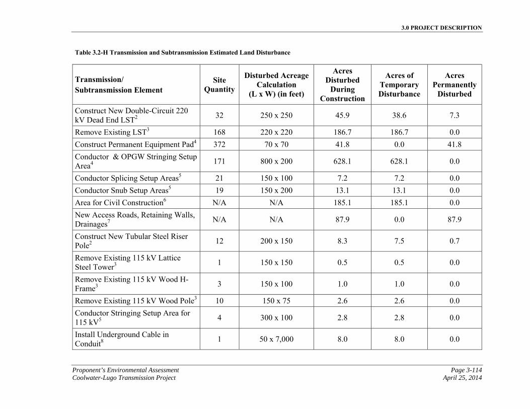
3.0 PROJECT DESCRIPTION
Proponent’s Environmental Assessment Page 3-114 Coolwater-Lugo Transmission Project April 25, 2014
Table 3.2-H Transmission and Subtransmission Estimated Land Disturbance
Transmission/ Subtransmission Element
Site Quantity
Disturbed Acreage Calculation
(L x W) (in feet)
Acres Disturbed
During Construction
Acres of Temporary Disturbance
Acres Permanently
Disturbed
Construct New Double-Circuit 220 kV Dead End LST2
32 250 x 250 45.9 38.6 7.3
Remove Existing LST3 168 220 x 220 186.7 186.7 0.0
Construct Permanent Equipment Pad4 372 70 x 70 41.8 0.0 41.8
Conductor & OPGW Stringing Setup Area4
171 800 x 200 628.1 628.1 0.0
Conductor Splicing Setup Areas5 21 150 x 100 7.2 7.2 0.0
Conductor Snub Setup Areas5 19 150 x 200 13.1 13.1 0.0
Area for Civil Construction6 N/A N/A 185.1 185.1 0.0
New Access Roads, Retaining Walls, Drainages7
N/A N/A 87.9 0.0 87.9
Construct New Tubular Steel Riser Pole2
12 200 x 150 8.3 7.5 0.7
Remove Existing 115 kV Lattice Steel Tower3
1 150 x 150 0.5 0.5 0.0
Remove Existing 115 kV Wood H-Frame3
3 150 x 100 1.0 1.0 0.0
Remove Existing 115 kV Wood Pole3 10 150 x 75 2.6 2.6 0.0
Conductor Stringing Setup Area for 115 kV5
4 300 x 100 2.8 2.8 0.0
Install Underground Cable in Conduit8
1 50 x 7,000 8.0 8.0 0.0
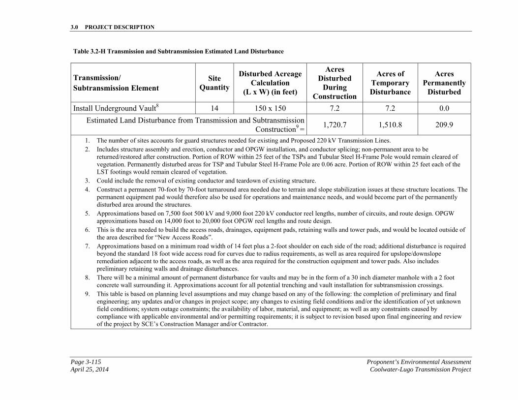
3.0 PROJECT DESCRIPTION
Page 3-115 Proponent’s Environmental Assessment April 25, 2014 Coolwater-Lugo Transmission Project
Table 3.2-H Transmission and Subtransmission Estimated Land Disturbance
Transmission/ Subtransmission Element
Site Quantity
Disturbed Acreage Calculation
(L x W) (in feet)
Acres Disturbed
During Construction
Acres of Temporary Disturbance
Acres Permanently
Disturbed
Install Underground Vault8 14 150 x 150 7.2 7.2 0.0
Estimated Land Disturbance from Transmission and Subtransmission Construction9 =
1,720.7 1,510.8 209.9
1. The number of sites accounts for guard structures needed for existing and Proposed 220 kV Transmission Lines. 2. Includes structure assembly and erection, conductor and OPGW installation, and conductor splicing; non-permanent area to be
returned/restored after construction. Portion of ROW within 25 feet of the TSPs and Tubular Steel H-Frame Pole would remain cleared of vegetation. Permanently disturbed areas for TSP and Tubular Steel H-Frame Pole are 0.06 acre. Portion of ROW within 25 feet each of the LST footings would remain cleared of vegetation.
3. Could include the removal of existing conductor and teardown of existing structure. 4. Construct a permanent 70-foot by 70-foot turnaround area needed due to terrain and slope stabilization issues at these structure locations. The
permanent equipment pad would therefore also be used for operations and maintenance needs, and would become part of the permanently disturbed area around the structures.
5. Approximations based on 7,500 foot 500 kV and 9,000 foot 220 kV conductor reel lengths, number of circuits, and route design. OPGW approximations based on 14,000 foot to 20,000 foot OPGW reel lengths and route design.
6. This is the area needed to build the access roads, drainages, equipment pads, retaining walls and tower pads, and would be located outside of the area described for “New Access Roads”.
7. Approximations based on a minimum road width of 14 feet plus a 2-foot shoulder on each side of the road; additional disturbance is required beyond the standard 18 foot wide access road for curves due to radius requirements, as well as area required for upslope/downslope remediation adjacent to the access roads, as well as the area required for the construction equipment and tower pads. Also includes preliminary retaining walls and drainage disturbances.
8. There will be a minimal amount of permanent disturbance for vaults and may be in the form of a 30 inch diameter manhole with a 2 foot concrete wall surrounding it. Approximations account for all potential trenching and vault installation for subtransmission crossings.
9. This table is based on planning level assumptions and may change based on any of the following: the completion of preliminary and final engineering; any updates and/or changes in project scope; any changes to existing field conditions and/or the identification of yet unknown field conditions; system outage constraints; the availability of labor, material, and equipment; as well as any constraints caused by compliance with applicable environmental and/or permitting requirements; it is subject to revision based upon final engineering and review of the project by SCE’s Construction Manager and/or Contractor.
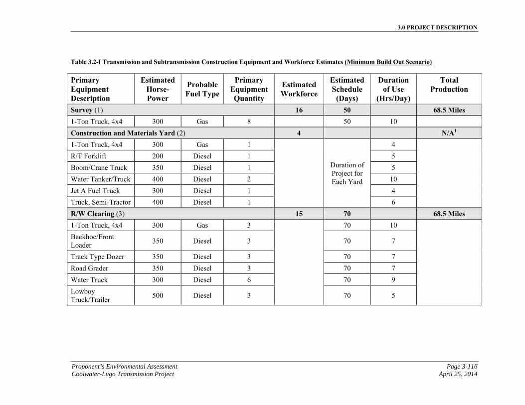
3.0 PROJECT DESCRIPTION
Proponent’s Environmental Assessment Page 3-116 Coolwater-Lugo Transmission Project April 25, 2014
Table 3.2-I Transmission and Subtransmission Construction Equipment and Workforce Estimates (Minimum Build Out Scenario)
Primary Equipment Description
EstimatedHorse-Power
ProbableFuel Type
Primary Equipment Quantity
Estimated Workforce
EstimatedSchedule
(Days)
Duration of Use
(Hrs/Day)
Total Production
Survey (1) 16 50 68.5 Miles 1-Ton Truck, 4x4 300 Gas 8 50 10
Construction and Materials Yard (2) 4 N/A1 1-Ton Truck, 4x4 300 Gas 1
Duration of Project for Each Yard
4
R/T Forklift 200 Diesel 1 5
Boom/Crane Truck 350 Diesel 1 5
Water Tanker/Truck 400 Diesel 2 10
Jet A Fuel Truck 300 Diesel 1 4
Truck, Semi-Tractor 400 Diesel 1 6
R/W Clearing (3) 15 70 68.5 Miles 1-Ton Truck, 4x4 300 Gas 3 70 10
Backhoe/Front Loader
350 Diesel 3 70 7
Track Type Dozer 350 Diesel 3 70 7
Road Grader 350 Diesel 3 70 7
Water Truck 300 Diesel 6 70 9
Lowboy Truck/Trailer
500 Diesel 3 70 5

3.0 PROJECT DESCRIPTION
Page 3-117 Proponent’s Environmental Assessment April 25, 2014 Coolwater-Lugo Transmission Project
Table 3.2-I Transmission and Subtransmission Construction Equipment and Workforce Estimates (Minimum Build Out Scenario)
Primary Equipment Description
EstimatedHorse-Power
ProbableFuel Type
Primary Equipment Quantity
Estimated Workforce
EstimatedSchedule
(Days)
Duration of Use
(Hrs/Day)
Total Production
Roads & Landing Work (4) 24 100 42.7 Miles &
372 Pads 1-Ton Truck, 4x4 300 Gas 8 100 5
Backhoe/Front Loader
350 Diesel 4 100 7
Track Type Dozer 350 Diesel 4 100 7
Motor Grader 350 Diesel 4 100 5
Water Truck 300 Diesel 8 100 10
Drum Type Compactor
250 Diesel 4 100 5
Excavator 300 Diesel 4 60 7
Lowboy Truck/Trailer
500 Diesel 4 60 4
Retaining Wall Installation (5) 12 200 2,964 Linear Feet 1-Ton Truck, 4x4 300 Gas 2 200 8
Boom Truck 350 Diesel 2 200 8
Tracked Drill Rig 250 Diesel 2 200 8
Rubber Tire Backhoe
125 Diesel 2 200 8
Wheel Loader 250 Diesel 2 200 8
Dump Truck 350 Diesel 4 200 8
Water Truck 300 Diesel 2 200 10
Concrete Redi-Mix Truck
350 Diesel 6 100 4
Flatbed Trailer - - 2 200 8
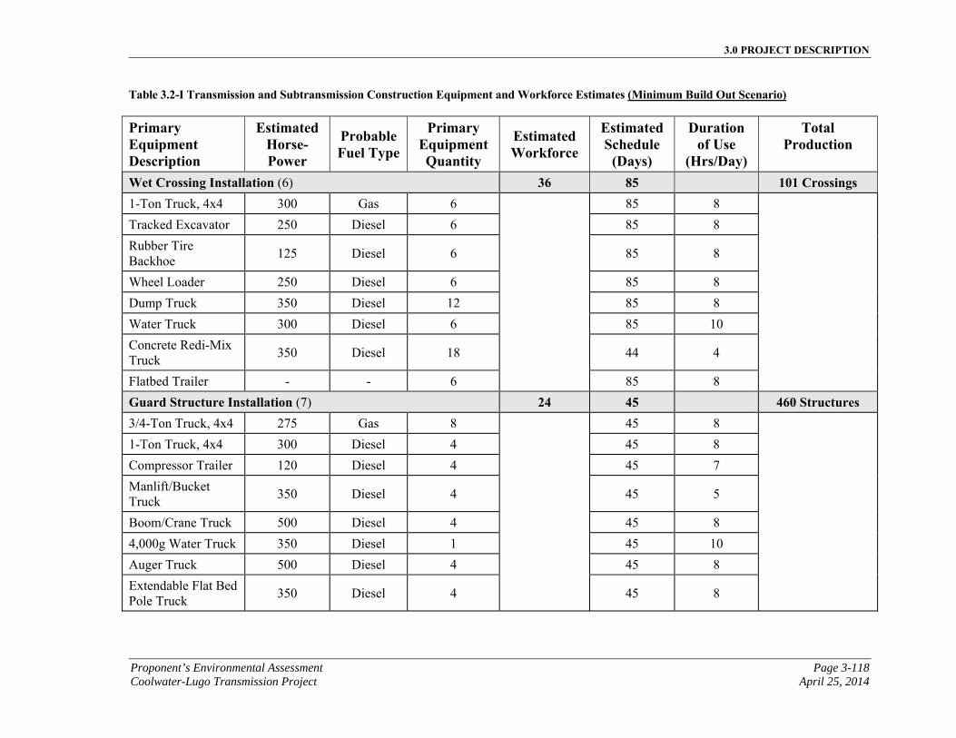
3.0 PROJECT DESCRIPTION
Proponent’s Environmental Assessment Page 3-118 Coolwater-Lugo Transmission Project April 25, 2014
Table 3.2-I Transmission and Subtransmission Construction Equipment and Workforce Estimates (Minimum Build Out Scenario)
Primary Equipment Description
EstimatedHorse-Power
ProbableFuel Type
Primary Equipment Quantity
Estimated Workforce
EstimatedSchedule
(Days)
Duration of Use
(Hrs/Day)
Total Production
Wet Crossing Installation (6) 36 85 101 Crossings 1-Ton Truck, 4x4 300 Gas 6 85 8
Tracked Excavator 250 Diesel 6 85 8
Rubber Tire Backhoe
125 Diesel 6 85 8
Wheel Loader 250 Diesel 6 85 8
Dump Truck 350 Diesel 12 85 8
Water Truck 300 Diesel 6 85 10
Concrete Redi-Mix Truck
350 Diesel 18 44 4
Flatbed Trailer - - 6 85 8
Guard Structure Installation (7) 24 45 460 Structures 3/4-Ton Truck, 4x4 275 Gas 8 45 8
1-Ton Truck, 4x4 300 Diesel 4 45 8
Compressor Trailer 120 Diesel 4 45 7
Manlift/Bucket Truck
350 Diesel 4 45 5
Boom/Crane Truck 500 Diesel 4 45 8
4,000g Water Truck 350 Diesel 1 45 10
Auger Truck 500 Diesel 4 45 8
Extendable Flat Bed Pole Truck
350 Diesel 4 45 8
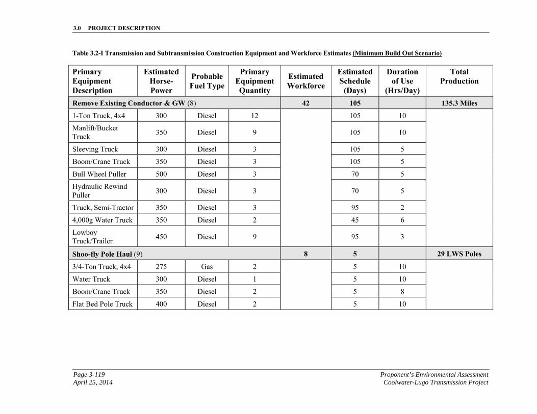
3.0 PROJECT DESCRIPTION
Page 3-119 Proponent’s Environmental Assessment April 25, 2014 Coolwater-Lugo Transmission Project
Table 3.2-I Transmission and Subtransmission Construction Equipment and Workforce Estimates (Minimum Build Out Scenario)
Primary Equipment Description
EstimatedHorse-Power
ProbableFuel Type
Primary Equipment Quantity
Estimated Workforce
EstimatedSchedule
(Days)
Duration of Use
(Hrs/Day)
Total Production
Remove Existing Conductor & GW (8) 42 105 135.3 Miles
1-Ton Truck, 4x4 300 Diesel 12 105 10
Manlift/Bucket Truck
350 Diesel 9 105 10
Sleeving Truck 300 Diesel 3 105 5
Boom/Crane Truck 350 Diesel 3 105 5
Bull Wheel Puller 500 Diesel 3 70 5
Hydraulic Rewind Puller
300 Diesel 3 70 5
Truck, Semi-Tractor 350 Diesel 3 95 2
4,000g Water Truck 350 Diesel 2 45 6
Lowboy Truck/Trailer
450 Diesel 9 95 3
Shoo-fly Pole Haul (9) 8 5 29 LWS Poles
3/4-Ton Truck, 4x4 275 Gas 2 5 10
Water Truck 300 Diesel 1 5 10
Boom/Crane Truck 350 Diesel 2 5 8
Flat Bed Pole Truck 400 Diesel 2 5 10
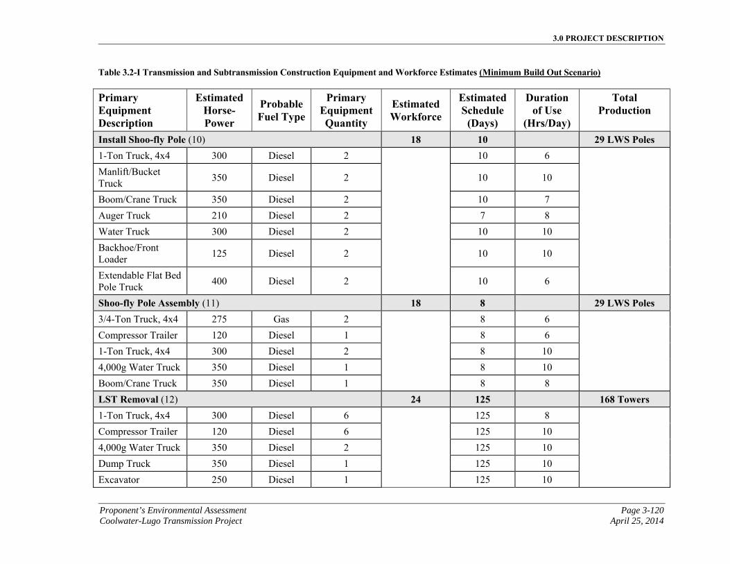
3.0 PROJECT DESCRIPTION
Proponent’s Environmental Assessment Page 3-120 Coolwater-Lugo Transmission Project April 25, 2014
Table 3.2-I Transmission and Subtransmission Construction Equipment and Workforce Estimates (Minimum Build Out Scenario)
Primary Equipment Description
EstimatedHorse-Power
ProbableFuel Type
Primary Equipment Quantity
Estimated Workforce
EstimatedSchedule
(Days)
Duration of Use
(Hrs/Day)
Total Production
Install Shoo-fly Pole (10) 18 10 29 LWS Poles 1-Ton Truck, 4x4 300 Diesel 2 10 6
Manlift/Bucket Truck
350 Diesel 2 10 10
Boom/Crane Truck 350 Diesel 2 10 7
Auger Truck 210 Diesel 2 7 8
Water Truck 300 Diesel 2 10 10
Backhoe/Front Loader
125 Diesel 2 10 10
Extendable Flat Bed Pole Truck
400 Diesel 2 10 6
Shoo-fly Pole Assembly (11) 18 8 29 LWS Poles 3/4-Ton Truck, 4x4 275 Gas 2 8 6
Compressor Trailer 120 Diesel 1 8 6
1-Ton Truck, 4x4 300 Diesel 2 8 10
4,000g Water Truck 350 Diesel 1 8 10
Boom/Crane Truck 350 Diesel 1 8 8
LST Removal (12) 24 125 168 Towers 1-Ton Truck, 4x4 300 Diesel 6 125 8
Compressor Trailer 120 Diesel 6 125 10
4,000g Water Truck 350 Diesel 2 125 10
Dump Truck 350 Diesel 1 125 10
Excavator 250 Diesel 1 125 10
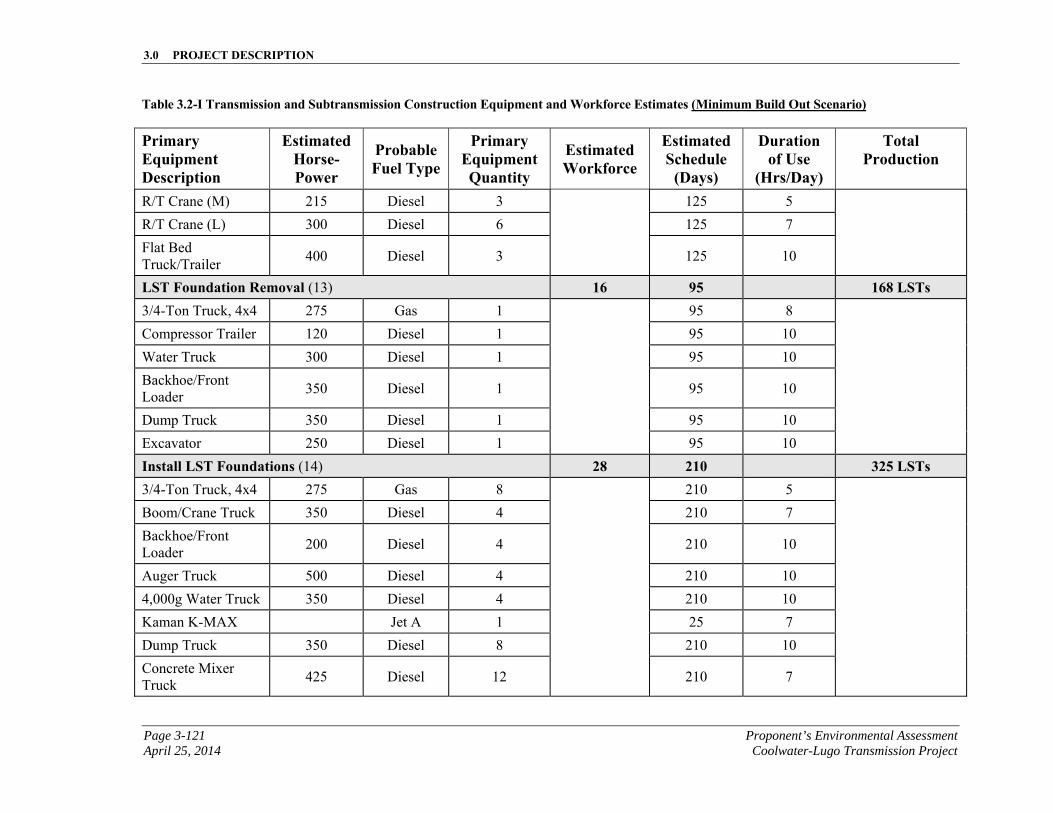
3.0 PROJECT DESCRIPTION
Page 3-121 Proponent’s Environmental Assessment April 25, 2014 Coolwater-Lugo Transmission Project
Table 3.2-I Transmission and Subtransmission Construction Equipment and Workforce Estimates (Minimum Build Out Scenario)
Primary Equipment Description
EstimatedHorse-Power
ProbableFuel Type
Primary Equipment Quantity
Estimated Workforce
EstimatedSchedule
(Days)
Duration of Use
(Hrs/Day)
Total Production
R/T Crane (M) 215 Diesel 3 125 5
R/T Crane (L) 300 Diesel 6 125 7
Flat Bed Truck/Trailer
400 Diesel 3 125 10
LST Foundation Removal (13) 16 95 168 LSTs 3/4-Ton Truck, 4x4 275 Gas 1 95 8
Compressor Trailer 120 Diesel 1 95 10
Water Truck 300 Diesel 1 95 10
Backhoe/Front Loader
350 Diesel 1 95 10
Dump Truck 350 Diesel 1 95 10
Excavator 250 Diesel 1 95 10
Install LST Foundations (14) 28 210 325 LSTs 3/4-Ton Truck, 4x4 275 Gas 8 210 5
Boom/Crane Truck 350 Diesel 4 210 7
Backhoe/Front Loader
200 Diesel 4 210 10
Auger Truck 500 Diesel 4 210 10
4,000g Water Truck 350 Diesel 4 210 10
Kaman K-MAX Jet A 1 25 7
Dump Truck 350 Diesel 8 210 10
Concrete Mixer Truck
425 Diesel 12 210 7
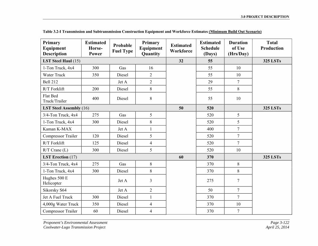
3.0 PROJECT DESCRIPTION
Proponent’s Environmental Assessment Page 3-122 Coolwater-Lugo Transmission Project April 25, 2014
Table 3.2-I Transmission and Subtransmission Construction Equipment and Workforce Estimates (Minimum Build Out Scenario)
Primary Equipment Description
EstimatedHorse-Power
ProbableFuel Type
Primary Equipment Quantity
Estimated Workforce
EstimatedSchedule
(Days)
Duration of Use
(Hrs/Day)
Total Production
LST Steel Haul (15) 32 55 325 LSTs 1-Ton Truck, 4x4 300 Gas 16 55 10
Water Truck 350 Diesel 2 55 10
Bell 212 Jet A 2 29 7
R/T Forklift 200 Diesel 8 55 8
Flat Bed Truck/Trailer
400 Diesel 8 55 10
LST Steel Assembly (16) 50 520 325 LSTs 3/4-Ton Truck, 4x4 275 Gas 5 520 5
1-Ton Truck, 4x4 300 Diesel 8 520 5
Kaman K-MAX Jet A 1 400 7
Compressor Trailer 120 Diesel 5 520 7
R/T Forklift 125 Diesel 4 520 7
R/T Crane (L) 300 Diesel 5 520 10
LST Erection (17) 60 370 325 LSTs 3/4-Ton Truck, 4x4 275 Gas 8 370 8
1-Ton Truck, 4x4 300 Diesel 8 370 8
Hughes 500 E Helicopter
Jet A 3 275 7
Sikorsky S64 Jet A 2 50 7
Jet A Fuel Truck 300 Diesel 1 370 7
4,000g Water Truck 350 Diesel 4 370 10
Compressor Trailer 60 Diesel 4 370 7
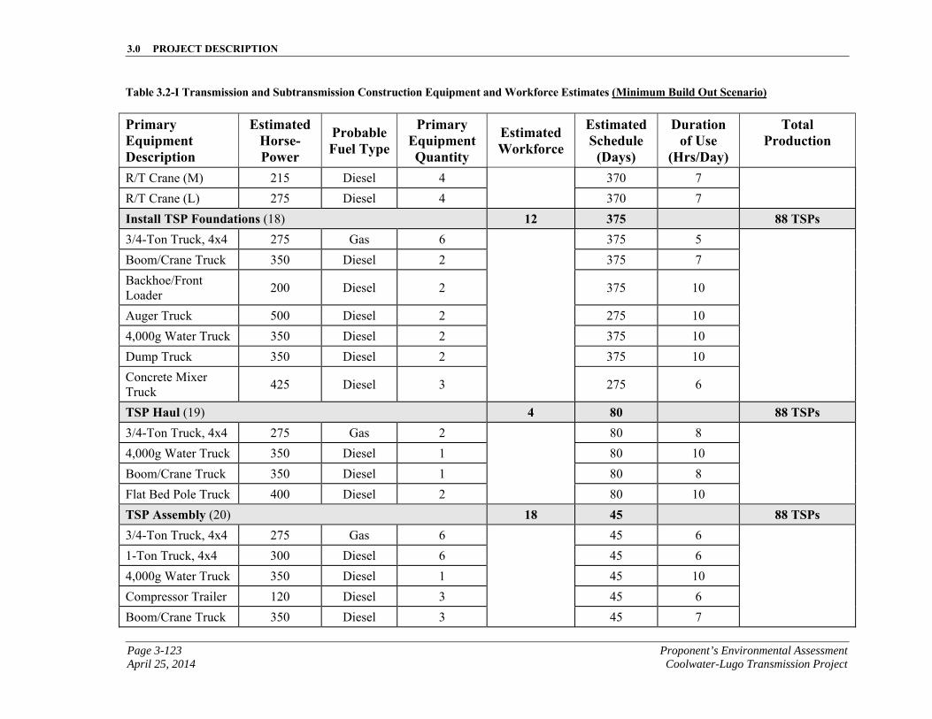
3.0 PROJECT DESCRIPTION
Page 3-123 Proponent’s Environmental Assessment April 25, 2014 Coolwater-Lugo Transmission Project
Table 3.2-I Transmission and Subtransmission Construction Equipment and Workforce Estimates (Minimum Build Out Scenario)
Primary Equipment Description
EstimatedHorse-Power
ProbableFuel Type
Primary Equipment Quantity
Estimated Workforce
EstimatedSchedule
(Days)
Duration of Use
(Hrs/Day)
Total Production
R/T Crane (M) 215 Diesel 4 370 7
R/T Crane (L) 275 Diesel 4 370 7
Install TSP Foundations (18) 12 375 88 TSPs 3/4-Ton Truck, 4x4 275 Gas 6 375 5
Boom/Crane Truck 350 Diesel 2 375 7
Backhoe/Front Loader
200 Diesel 2 375 10
Auger Truck 500 Diesel 2 275 10
4,000g Water Truck 350 Diesel 2 375 10
Dump Truck 350 Diesel 2 375 10
Concrete Mixer Truck
425 Diesel 3 275 6
TSP Haul (19) 4 80 88 TSPs 3/4-Ton Truck, 4x4 275 Gas 2 80 8
4,000g Water Truck 350 Diesel 1 80 10
Boom/Crane Truck 350 Diesel 1 80 8
Flat Bed Pole Truck 400 Diesel 2 80 10
TSP Assembly (20) 18 45 88 TSPs 3/4-Ton Truck, 4x4 275 Gas 6 45 6
1-Ton Truck, 4x4 300 Diesel 6 45 6
4,000g Water Truck 350 Diesel 1 45 10
Compressor Trailer 120 Diesel 3 45 6
Boom/Crane Truck 350 Diesel 3 45 7
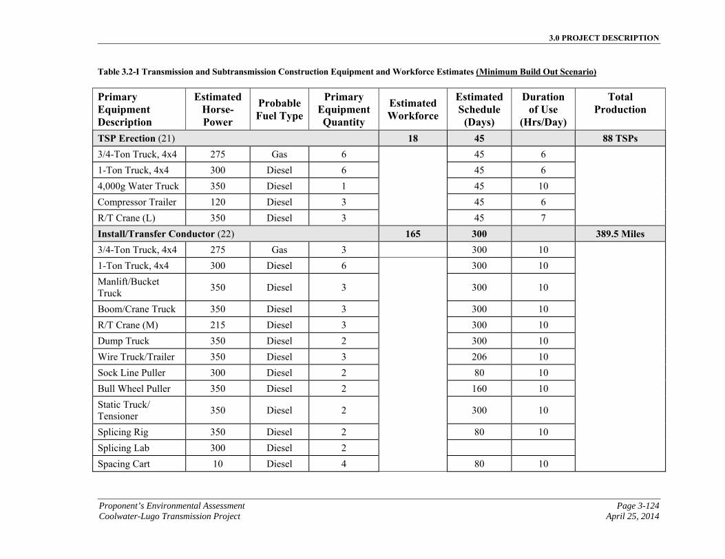
3.0 PROJECT DESCRIPTION
Proponent’s Environmental Assessment Page 3-124 Coolwater-Lugo Transmission Project April 25, 2014
Table 3.2-I Transmission and Subtransmission Construction Equipment and Workforce Estimates (Minimum Build Out Scenario)
Primary Equipment Description
EstimatedHorse-Power
ProbableFuel Type
Primary Equipment Quantity
Estimated Workforce
EstimatedSchedule
(Days)
Duration of Use
(Hrs/Day)
Total Production
TSP Erection (21) 18 45 88 TSPs 3/4-Ton Truck, 4x4 275 Gas 6 45 6
1-Ton Truck, 4x4 300 Diesel 6 45 6
4,000g Water Truck 350 Diesel 1 45 10
Compressor Trailer 120 Diesel 3 45 6
R/T Crane (L) 350 Diesel 3 45 7
Install/Transfer Conductor (22) 165 300 389.5 Miles 3/4-Ton Truck, 4x4 275 Gas 3 300 10
1-Ton Truck, 4x4 300 Diesel 6 300 10
Manlift/Bucket Truck
350 Diesel 3 300 10
Boom/Crane Truck 350 Diesel 3 300 10
R/T Crane (M) 215 Diesel 3 300 10
Dump Truck 350 Diesel 2 300 10
Wire Truck/Trailer 350 Diesel 3 206 10
Sock Line Puller 300 Diesel 2 80 10
Bull Wheel Puller 350 Diesel 2 160 10
Static Truck/ Tensioner
350 Diesel 2 300 10
Splicing Rig 350 Diesel 2 80 10
Splicing Lab 300 Diesel 2
Spacing Cart 10 Diesel 4 80 10
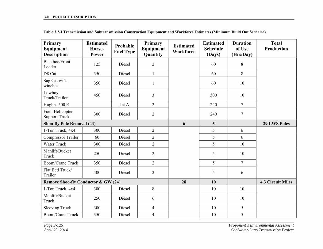
3.0 PROJECT DESCRIPTION
Page 3-125 Proponent’s Environmental Assessment April 25, 2014 Coolwater-Lugo Transmission Project
Table 3.2-I Transmission and Subtransmission Construction Equipment and Workforce Estimates (Minimum Build Out Scenario)
Primary Equipment Description
EstimatedHorse-Power
ProbableFuel Type
Primary Equipment Quantity
Estimated Workforce
EstimatedSchedule
(Days)
Duration of Use
(Hrs/Day)
Total Production
Backhoe/Front Loader
125 Diesel 2 60 8
D8 Cat 350 Diesel 1 60 8
Sag Cat w/ 2 winches
350 Diesel 1 60 10
Lowboy Truck/Trailer
450 Diesel 3 300 10
Hughes 500 E Jet A 2 240 7
Fuel, Helicopter Support Truck
300 Diesel 2 240 7
Shoo-fly Pole Removal (23) 6 5 29 LWS Poles 1-Ton Truck, 4x4 300 Diesel 2 5 6
Compressor Trailer 60 Diesel 2 5 6
Water Truck 300 Diesel 2 5 10
Manlift/Bucket Truck
250 Diesel 2 5 10
Boom/Crane Truck 350 Diesel 2 5 7
Flat Bed Truck/ Trailer
400 Diesel 2 5 6
Remove Shoo-fly Conductor & GW (24) 28 10 4.3 Circuit Miles 1-Ton Truck, 4x4 300 Diesel 8 10 10
Manlift/Bucket Truck
250 Diesel 6 10 10
Sleeving Truck 300 Diesel 4 10 5
Boom/Crane Truck 350 Diesel 4 10 5
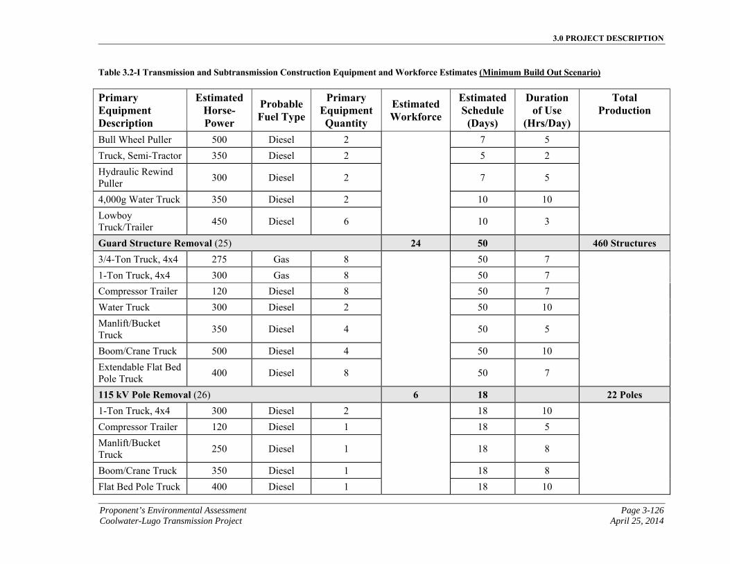
3.0 PROJECT DESCRIPTION
Proponent’s Environmental Assessment Page 3-126 Coolwater-Lugo Transmission Project April 25, 2014
Table 3.2-I Transmission and Subtransmission Construction Equipment and Workforce Estimates (Minimum Build Out Scenario)
Primary Equipment Description
EstimatedHorse-Power
ProbableFuel Type
Primary Equipment Quantity
Estimated Workforce
EstimatedSchedule
(Days)
Duration of Use
(Hrs/Day)
Total Production
Bull Wheel Puller 500 Diesel 2 7 5
Truck, Semi-Tractor 350 Diesel 2 5 2
Hydraulic Rewind Puller
300 Diesel 2 7 5
4,000g Water Truck 350 Diesel 2 10 10
Lowboy Truck/Trailer
450 Diesel 6 10 3
Guard Structure Removal (25) 24 50 460 Structures 3/4-Ton Truck, 4x4 275 Gas 8 50 7
1-Ton Truck, 4x4 300 Gas 8 50 7
Compressor Trailer 120 Diesel 8 50 7
Water Truck 300 Diesel 2 50 10
Manlift/Bucket Truck
350 Diesel 4 50 5
Boom/Crane Truck 500 Diesel 4 50 10
Extendable Flat Bed Pole Truck
400 Diesel 8 50 7
115 kV Pole Removal (26) 6 18 22 Poles 1-Ton Truck, 4x4 300 Diesel 2 18 10
Compressor Trailer 120 Diesel 1 18 5
Manlift/Bucket Truck
250 Diesel 1 18 8
Boom/Crane Truck 350 Diesel 1 18 8
Flat Bed Pole Truck 400 Diesel 1 18 10

3.0 PROJECT DESCRIPTION
Page 3-127 Proponent’s Environmental Assessment April 25, 2014 Coolwater-Lugo Transmission Project
Table 3.2-I Transmission and Subtransmission Construction Equipment and Workforce Estimates (Minimum Build Out Scenario)
Primary Equipment Description
EstimatedHorse-Power
ProbableFuel Type
Primary Equipment Quantity
Estimated Workforce
EstimatedSchedule
(Days)
Duration of Use
(Hrs/Day)
Total Production
Install TSP Riser Foundations (27) 12 50 12 TSPs 3/4-Ton Truck, 4x4 275 Gas 3 50 5
Boom/Crane Truck 350 Diesel 1 50 7
Backhoe/Front Loader
200 Diesel 1 50 10
Auger Truck 500 Diesel 1 35 10
4,000g Water Truck 350 Diesel 1 50 10
Dump Truck 350 Diesel 2 50 10
Concrete Mixer Truck
425 Diesel 3 35 6
TSP Riser Haul (28) 4 8 12 TSPs 3/4-Ton Truck, 4x4 275 Gas 2 8 8
4,000g Water Truck 350 Diesel 1 8 10
Boom/Crane Truck 350 Diesel 1 8 8
Flat Bed Pole Truck 400 Diesel 2 8 10
TSP Riser Assembly (29) 18 25 12 TSPs 3/4-Ton Truck, 4x4 275 Gas 6 25 6
1-Ton Truck, 4x4 300 Diesel 6 25 6
4,000g Water Truck 350 Diesel 1 25 10
Compressor Trailer 120 Diesel 3 25 6
Boom/Crane Truck 350 Diesel 3 25 7
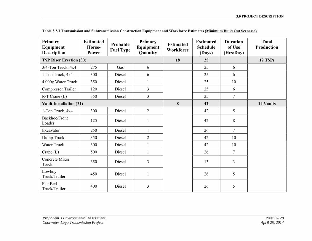
3.0 PROJECT DESCRIPTION
Proponent’s Environmental Assessment Page 3-128 Coolwater-Lugo Transmission Project April 25, 2014
Table 3.2-I Transmission and Subtransmission Construction Equipment and Workforce Estimates (Minimum Build Out Scenario)
Primary Equipment Description
EstimatedHorse-Power
ProbableFuel Type
Primary Equipment Quantity
Estimated Workforce
EstimatedSchedule
(Days)
Duration of Use
(Hrs/Day)
Total Production
TSP Riser Erection (30) 18 25 12 TSPs
3/4-Ton Truck, 4x4 275 Gas 6 25 6
1-Ton Truck, 4x4 300 Diesel 6 25 6
4,000g Water Truck 350 Diesel 1 25 10
Compressor Trailer 120 Diesel 3 25 6
R/T Crane (L) 350 Diesel 3 25 7
Vault Installation (31) 8 42 14 Vaults
1-Ton Truck, 4x4 300 Diesel 2 42 5
Backhoe/Front Loader
125 Diesel 1 42 8
Excavator 250 Diesel 1 26 7
Dump Truck 350 Diesel 2 42 10
Water Truck 300 Diesel 1 42 10
Crane (L) 500 Diesel 1 26 7
Concrete Mixer Truck
350 Diesel 3 13 3
Lowboy Truck/Trailer
450 Diesel 1 26 5
Flat Bed Truck/Trailer
400 Diesel 3 26 5

3.0 PROJECT DESCRIPTION
Page 3-129 Proponent’s Environmental Assessment April 25, 2014 Coolwater-Lugo Transmission Project
Table 3.2-I Transmission and Subtransmission Construction Equipment and Workforce Estimates (Minimum Build Out Scenario)
Primary Equipment Description
EstimatedHorse-Power
ProbableFuel Type
Primary Equipment Quantity
Estimated Workforce
EstimatedSchedule
(Days)
Duration of Use
(Hrs/Day)
Total Production
Duct Bank Installation (32) 8 35 7,000 Trench Feet 1-Ton Truck, 4x4 300 Diesel 2 35 5
Compressor Trailer 120 Diesel 1 30 5
Backhoe/Front Loader
125 Diesel 1 35 7
Dump Truck 350 Diesel 3 30 7
Pipe Truck/Trailer 275 Diesel 1 30 7
Water Truck 300 Diesel 1 35 10
Concrete Mixer Truck
350 Diesel 3 10 4
Flat Bed Truck/Trailer
400 Diesel 3 35 5
Lowboy Truck/Trailer
450 Diesel 1 35 5
Install Underground Cable (33) 8 35 7,000 Feet 1-Ton Truck, 4x4 300 Diesel 2 35 5
Manlift/Bucket Truck
250 Diesel 4 35 5
Boom/Crane Truck 350 Diesel 1 7 7
Water Truck 300 Diesel 1 35 10
Pipe Truck/Trailer 275 Diesel 1 30 7
Wire Truck/Trailer 350 Diesel 1 30 5
Puller 350 Diesel 2 35 5
Flat Bed Truck/Trailer
400 Diesel 3 35 5
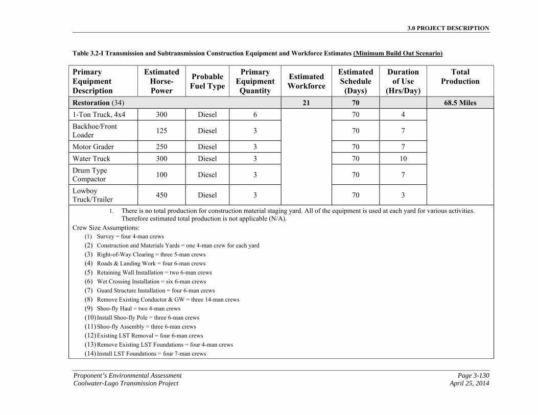
3.0 PROJECT DESCRIPTION
Proponent’s Environmental Assessment Page 3-130 Coolwater-Lugo Transmission Project April 25, 2014
Table 3.2-I Transmission and Subtransmission Construction Equipment and Workforce Estimates (Minimum Build Out Scenario)
Primary Equipment Description
EstimatedHorse-Power
ProbableFuel Type
Primary Equipment Quantity
Estimated Workforce
EstimatedSchedule
(Days)
Duration of Use
(Hrs/Day)
Total Production
Restoration (34) 21 70 68.5 Miles 1-Ton Truck, 4x4 300 Diesel 6 70 4
Backhoe/Front Loader
125 Diesel 3 70 7
Motor Grader 250 Diesel 3 70 7
Water Truck 300 Diesel 3 70 10
Drum Type Compactor
100 Diesel 3 70 7
Lowboy Truck/Trailer
450 Diesel 3 70 3
1. There is no total production for construction material staging yard. All of the equipment is used at each yard for various activities. Therefore estimated total production is not applicable (N/A).
Crew Size Assumptions: (1) Survey = four 4-man crews
(2) Construction and Materials Yards = one 4-man crew for each yard (3) Right-of-Way Clearing = three 5-man crews (4) Roads & Landing Work = four 6-man crews (5) Retaining Wall Installation = two 6-man crews (6) Wet Crossing Installation = six 6-man crews (7) Guard Structure Installation = four 6-man crews (8) Remove Existing Conductor & GW = three 14-man crews (9) Shoo-fly Haul = two 4-man crews (10) Install Shoo-fly Pole = three 6-man crews (11) Shoo-fly Assembly = three 6-man crews (12) Existing LST Removal = four 6-man crews (13) Remove Existing LST Foundations = four 4-man crews (14) Install LST Foundations = four 7-man crews
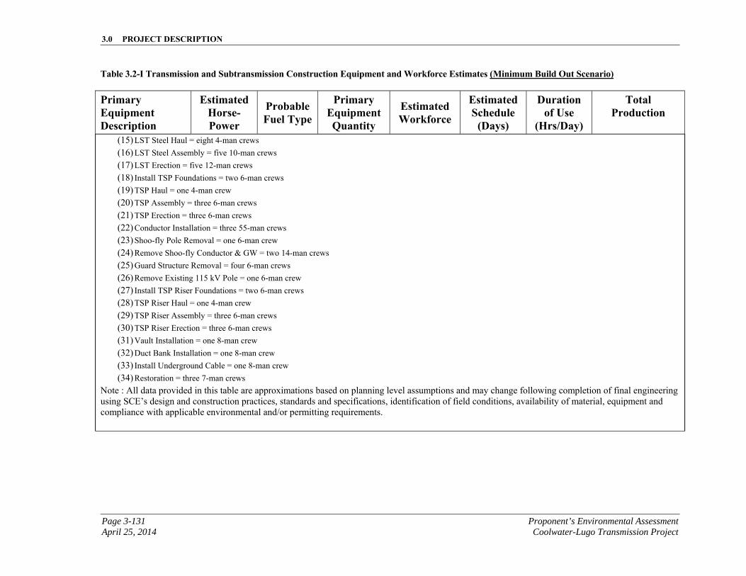
3.0 PROJECT DESCRIPTION
Page 3-131 Proponent’s Environmental Assessment April 25, 2014 Coolwater-Lugo Transmission Project
Table 3.2-I Transmission and Subtransmission Construction Equipment and Workforce Estimates (Minimum Build Out Scenario)
Primary Equipment Description
EstimatedHorse-Power
ProbableFuel Type
Primary Equipment Quantity
Estimated Workforce
EstimatedSchedule
(Days)
Duration of Use
(Hrs/Day)
Total Production
(15) LST Steel Haul = eight 4-man crews (16) LST Steel Assembly = five 10-man crews (17) LST Erection = five 12-man crews (18) Install TSP Foundations = two 6-man crews (19) TSP Haul = one 4-man crew (20) TSP Assembly = three 6-man crews (21) TSP Erection = three 6-man crews (22) Conductor Installation = three 55-man crews (23) Shoo-fly Pole Removal = one 6-man crew (24) Remove Shoo-fly Conductor & GW = two 14-man crews (25) Guard Structure Removal = four 6-man crews (26) Remove Existing 115 kV Pole = one 6-man crew (27) Install TSP Riser Foundations = two 6-man crews (28) TSP Riser Haul = one 4-man crew (29) TSP Riser Assembly = three 6-man crews (30) TSP Riser Erection = three 6-man crews (31) Vault Installation = one 8-man crew (32) Duct Bank Installation = one 8-man crew (33) Install Underground Cable = one 8-man crew (34) Restoration = three 7-man crews
Note : All data provided in this table are approximations based on planning level assumptions and may change following completion of final engineering using SCE’s design and construction practices, standards and specifications, identification of field conditions, availability of material, equipment and compliance with applicable environmental and/or permitting requirements.
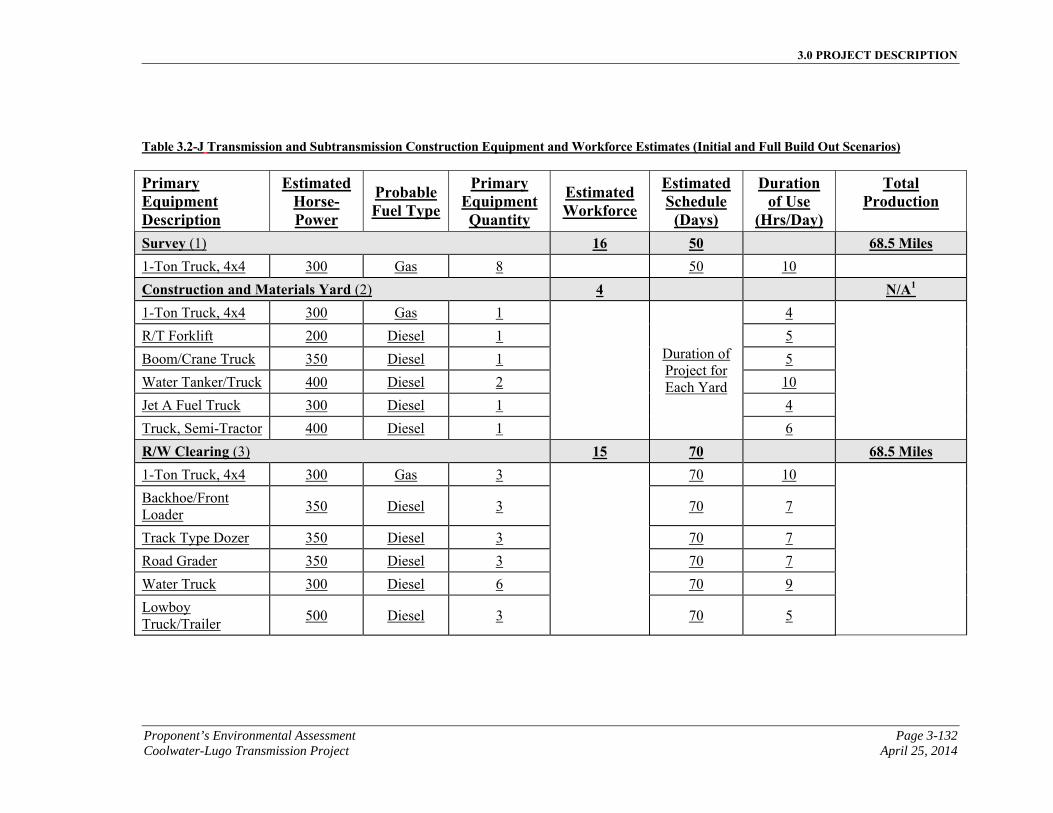
3.0 PROJECT DESCRIPTION
Proponent’s Environmental Assessment Page 3-132 Coolwater-Lugo Transmission Project April 25, 2014
Table 3.2-J Transmission and Subtransmission Construction Equipment and Workforce Estimates (Initial and Full Build Out Scenarios)
Primary Equipment Description
EstimatedHorse-Power
ProbableFuel Type
Primary Equipment Quantity
Estimated Workforce
EstimatedSchedule
(Days)
Duration of Use
(Hrs/Day)
Total Production
Survey (1) 16 50 68.5 Miles 1-Ton Truck, 4x4 300 Gas 8 50 10
Construction and Materials Yard (2) 4 N/A1 1-Ton Truck, 4x4 300 Gas 1
Duration of Project for Each Yard
4
R/T Forklift 200 Diesel 1 5
Boom/Crane Truck 350 Diesel 1 5
Water Tanker/Truck 400 Diesel 2 10
Jet A Fuel Truck 300 Diesel 1 4
Truck, Semi-Tractor 400 Diesel 1 6
R/W Clearing (3) 15 70 68.5 Miles 1-Ton Truck, 4x4 300 Gas 3 70 10
Backhoe/Front Loader
350 Diesel 3 70 7
Track Type Dozer 350 Diesel 3 70 7
Road Grader 350 Diesel 3 70 7
Water Truck 300 Diesel 6 70 9
Lowboy Truck/Trailer
500 Diesel 3 70 5
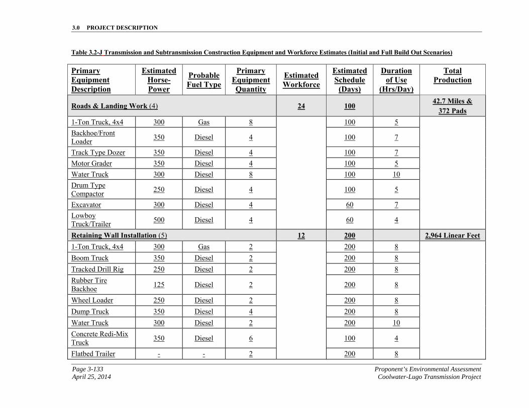
3.0 PROJECT DESCRIPTION
Page 3-133 Proponent’s Environmental Assessment April 25, 2014 Coolwater-Lugo Transmission Project
Table 3.2-J Transmission and Subtransmission Construction Equipment and Workforce Estimates (Initial and Full Build Out Scenarios)
Primary Equipment Description
EstimatedHorse-Power
ProbableFuel Type
Primary Equipment Quantity
Estimated Workforce
EstimatedSchedule
(Days)
Duration of Use
(Hrs/Day)
Total Production
Roads & Landing Work (4) 24 100 42.7 Miles &
372 Pads 1-Ton Truck, 4x4 300 Gas 8 100 5
Backhoe/Front Loader
350 Diesel 4 100 7
Track Type Dozer 350 Diesel 4 100 7
Motor Grader 350 Diesel 4 100 5
Water Truck 300 Diesel 8 100 10
Drum Type Compactor
250 Diesel 4 100 5
Excavator 300 Diesel 4 60 7
Lowboy Truck/Trailer
500 Diesel 4 60 4
Retaining Wall Installation (5) 12 200 2,964 Linear Feet 1-Ton Truck, 4x4 300 Gas 2 200 8
Boom Truck 350 Diesel 2 200 8
Tracked Drill Rig 250 Diesel 2 200 8
Rubber Tire Backhoe
125 Diesel 2 200 8
Wheel Loader 250 Diesel 2 200 8
Dump Truck 350 Diesel 4 200 8
Water Truck 300 Diesel 2 200 10
Concrete Redi-Mix Truck
350 Diesel 6 100 4
Flatbed Trailer - - 2 200 8
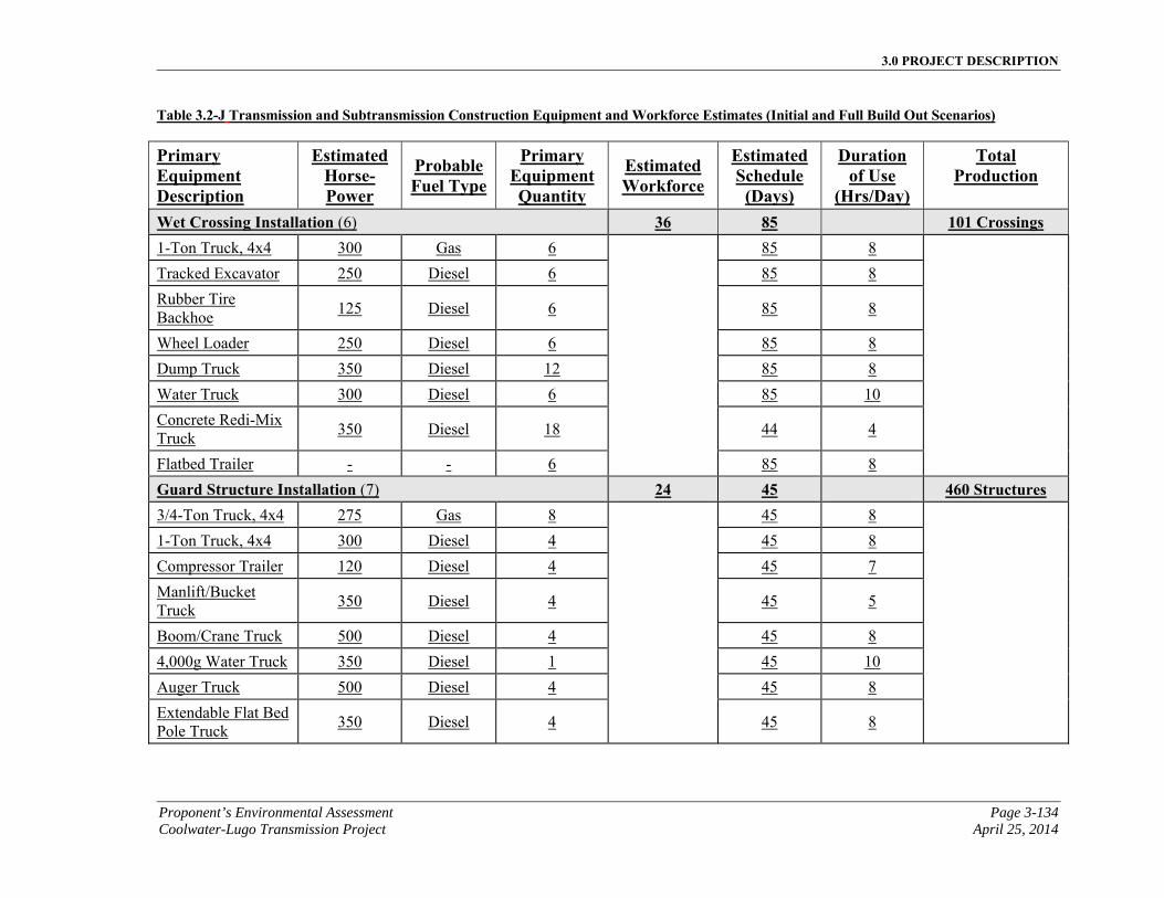
3.0 PROJECT DESCRIPTION
Proponent’s Environmental Assessment Page 3-134 Coolwater-Lugo Transmission Project April 25, 2014
Table 3.2-J Transmission and Subtransmission Construction Equipment and Workforce Estimates (Initial and Full Build Out Scenarios)
Primary Equipment Description
EstimatedHorse-Power
ProbableFuel Type
Primary Equipment Quantity
Estimated Workforce
EstimatedSchedule
(Days)
Duration of Use
(Hrs/Day)
Total Production
Wet Crossing Installation (6) 36 85 101 Crossings 1-Ton Truck, 4x4 300 Gas 6 85 8
Tracked Excavator 250 Diesel 6 85 8
Rubber Tire Backhoe
125 Diesel 6 85 8
Wheel Loader 250 Diesel 6 85 8
Dump Truck 350 Diesel 12 85 8
Water Truck 300 Diesel 6 85 10
Concrete Redi-Mix Truck
350 Diesel 18 44 4
Flatbed Trailer - - 6 85 8
Guard Structure Installation (7) 24 45 460 Structures 3/4-Ton Truck, 4x4 275 Gas 8 45 8
1-Ton Truck, 4x4 300 Diesel 4 45 8
Compressor Trailer 120 Diesel 4 45 7
Manlift/Bucket Truck
350 Diesel 4 45 5
Boom/Crane Truck 500 Diesel 4 45 8
4,000g Water Truck 350 Diesel 1 45 10
Auger Truck 500 Diesel 4 45 8
Extendable Flat Bed Pole Truck
350 Diesel 4 45 8
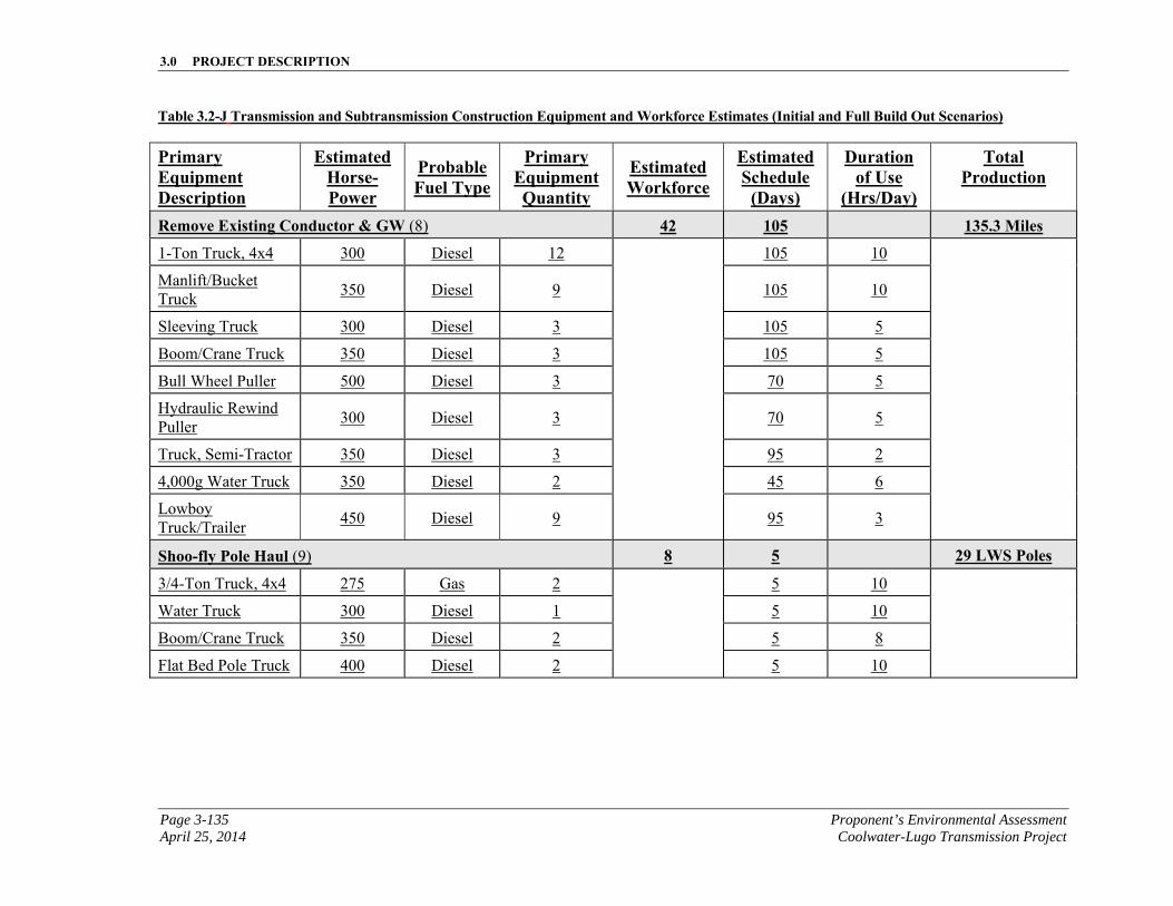
3.0 PROJECT DESCRIPTION
Page 3-135 Proponent’s Environmental Assessment April 25, 2014 Coolwater-Lugo Transmission Project
Table 3.2-J Transmission and Subtransmission Construction Equipment and Workforce Estimates (Initial and Full Build Out Scenarios)
Primary Equipment Description
EstimatedHorse-Power
ProbableFuel Type
Primary Equipment Quantity
Estimated Workforce
EstimatedSchedule
(Days)
Duration of Use
(Hrs/Day)
Total Production
Remove Existing Conductor & GW (8) 42 105 135.3 Miles
1-Ton Truck, 4x4 300 Diesel 12 105 10
Manlift/Bucket Truck
350 Diesel 9 105 10
Sleeving Truck 300 Diesel 3 105 5
Boom/Crane Truck 350 Diesel 3 105 5
Bull Wheel Puller 500 Diesel 3 70 5
Hydraulic Rewind Puller
300 Diesel 3 70 5
Truck, Semi-Tractor 350 Diesel 3 95 2
4,000g Water Truck 350 Diesel 2 45 6
Lowboy Truck/Trailer
450 Diesel 9 95 3
Shoo-fly Pole Haul (9) 8 5 29 LWS Poles
3/4-Ton Truck, 4x4 275 Gas 2 5 10
Water Truck 300 Diesel 1 5 10
Boom/Crane Truck 350 Diesel 2 5 8
Flat Bed Pole Truck 400 Diesel 2 5 10
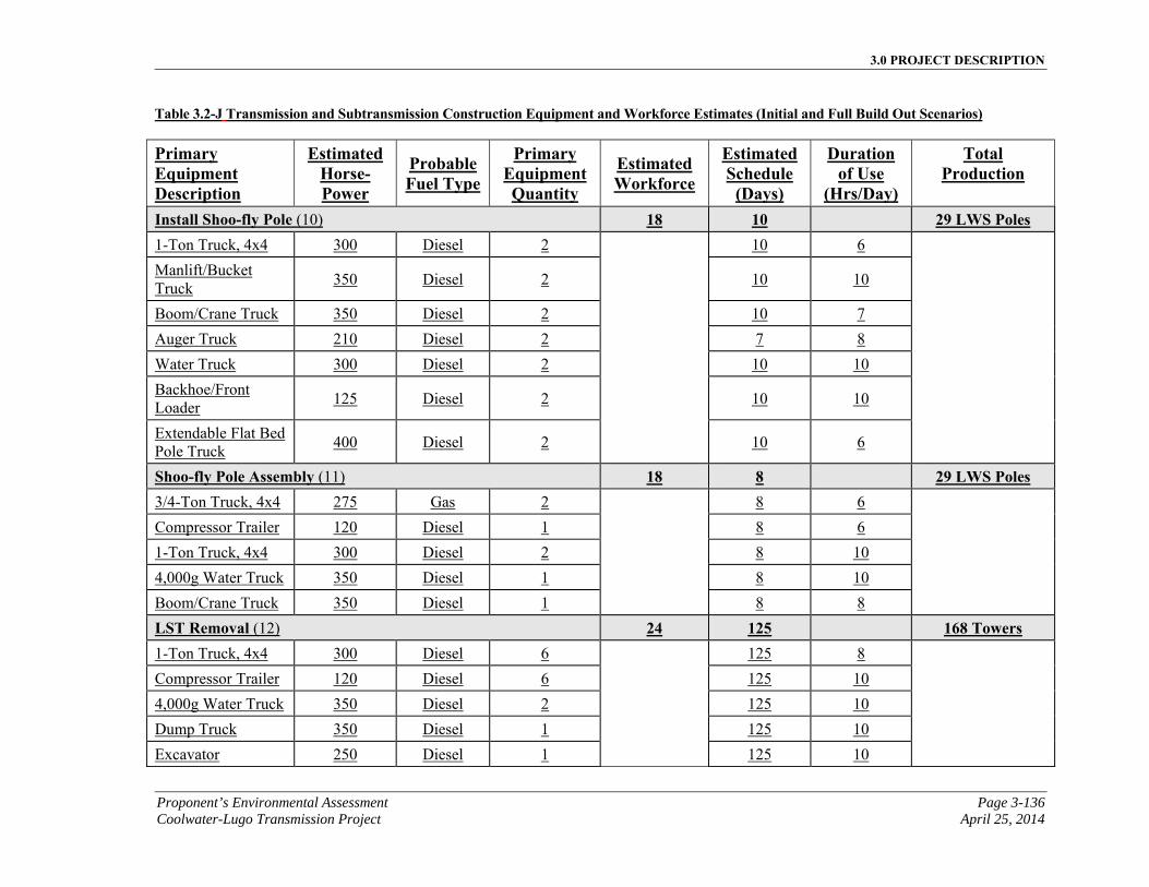
3.0 PROJECT DESCRIPTION
Proponent’s Environmental Assessment Page 3-136 Coolwater-Lugo Transmission Project April 25, 2014
Table 3.2-J Transmission and Subtransmission Construction Equipment and Workforce Estimates (Initial and Full Build Out Scenarios)
Primary Equipment Description
EstimatedHorse-Power
ProbableFuel Type
Primary Equipment Quantity
Estimated Workforce
EstimatedSchedule
(Days)
Duration of Use
(Hrs/Day)
Total Production
Install Shoo-fly Pole (10) 18 10 29 LWS Poles 1-Ton Truck, 4x4 300 Diesel 2 10 6
Manlift/Bucket Truck
350 Diesel 2 10 10
Boom/Crane Truck 350 Diesel 2 10 7
Auger Truck 210 Diesel 2 7 8
Water Truck 300 Diesel 2 10 10
Backhoe/Front Loader
125 Diesel 2 10 10
Extendable Flat Bed Pole Truck
400 Diesel 2 10 6
Shoo-fly Pole Assembly (11) 18 8 29 LWS Poles 3/4-Ton Truck, 4x4 275 Gas 2 8 6
Compressor Trailer 120 Diesel 1 8 6
1-Ton Truck, 4x4 300 Diesel 2 8 10
4,000g Water Truck 350 Diesel 1 8 10
Boom/Crane Truck 350 Diesel 1 8 8
LST Removal (12) 24 125 168 Towers 1-Ton Truck, 4x4 300 Diesel 6 125 8
Compressor Trailer 120 Diesel 6 125 10
4,000g Water Truck 350 Diesel 2 125 10
Dump Truck 350 Diesel 1 125 10
Excavator 250 Diesel 1 125 10
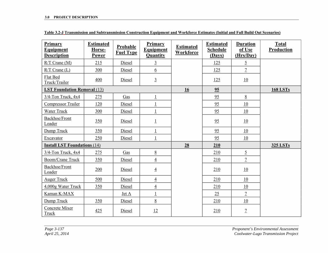
3.0 PROJECT DESCRIPTION
Page 3-137 Proponent’s Environmental Assessment April 25, 2014 Coolwater-Lugo Transmission Project
Table 3.2-J Transmission and Subtransmission Construction Equipment and Workforce Estimates (Initial and Full Build Out Scenarios)
Primary Equipment Description
EstimatedHorse-Power
ProbableFuel Type
Primary Equipment Quantity
Estimated Workforce
EstimatedSchedule
(Days)
Duration of Use
(Hrs/Day)
Total Production
R/T Crane (M) 215 Diesel 3 125 5
R/T Crane (L) 300 Diesel 6 125 7
Flat Bed Truck/Trailer
400 Diesel 3 125 10
LST Foundation Removal (13) 16 95 168 LSTs 3/4-Ton Truck, 4x4 275 Gas 1 95 8
Compressor Trailer 120 Diesel 1 95 10
Water Truck 300 Diesel 1 95 10
Backhoe/Front Loader
350 Diesel 1 95 10
Dump Truck 350 Diesel 1 95 10
Excavator 250 Diesel 1 95 10
Install LST Foundations (14) 28 210 325 LSTs 3/4-Ton Truck, 4x4 275 Gas 8 210 5
Boom/Crane Truck 350 Diesel 4 210 7
Backhoe/Front Loader
200 Diesel 4 210 10
Auger Truck 500 Diesel 4 210 10
4,000g Water Truck 350 Diesel 4 210 10
Kaman K-MAX Jet A 1 25 7
Dump Truck 350 Diesel 8 210 10
Concrete Mixer Truck
425 Diesel 12 210 7
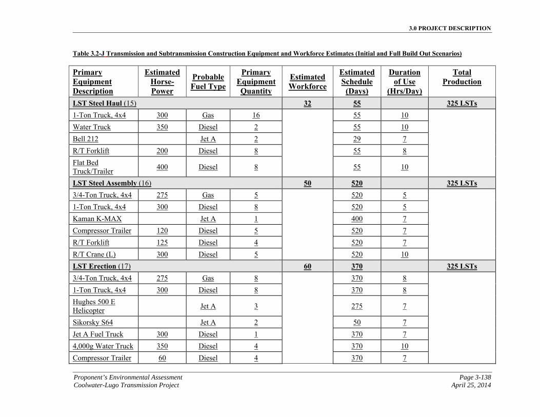
3.0 PROJECT DESCRIPTION
Proponent’s Environmental Assessment Page 3-138 Coolwater-Lugo Transmission Project April 25, 2014
Table 3.2-J Transmission and Subtransmission Construction Equipment and Workforce Estimates (Initial and Full Build Out Scenarios)
Primary Equipment Description
EstimatedHorse-Power
ProbableFuel Type
Primary Equipment Quantity
Estimated Workforce
EstimatedSchedule
(Days)
Duration of Use
(Hrs/Day)
Total Production
LST Steel Haul (15) 32 55 325 LSTs 1-Ton Truck, 4x4 300 Gas 16 55 10
Water Truck 350 Diesel 2 55 10
Bell 212 Jet A 2 29 7
R/T Forklift 200 Diesel 8 55 8
Flat Bed Truck/Trailer
400 Diesel 8 55 10
LST Steel Assembly (16) 50 520 325 LSTs 3/4-Ton Truck, 4x4 275 Gas 5 520 5
1-Ton Truck, 4x4 300 Diesel 8 520 5
Kaman K-MAX Jet A 1 400 7
Compressor Trailer 120 Diesel 5 520 7
R/T Forklift 125 Diesel 4 520 7
R/T Crane (L) 300 Diesel 5 520 10
LST Erection (17) 60 370 325 LSTs 3/4-Ton Truck, 4x4 275 Gas 8 370 8
1-Ton Truck, 4x4 300 Diesel 8 370 8
Hughes 500 E Helicopter
Jet A 3 275 7
Sikorsky S64 Jet A 2 50 7
Jet A Fuel Truck 300 Diesel 1 370 7
4,000g Water Truck 350 Diesel 4 370 10
Compressor Trailer 60 Diesel 4 370 7
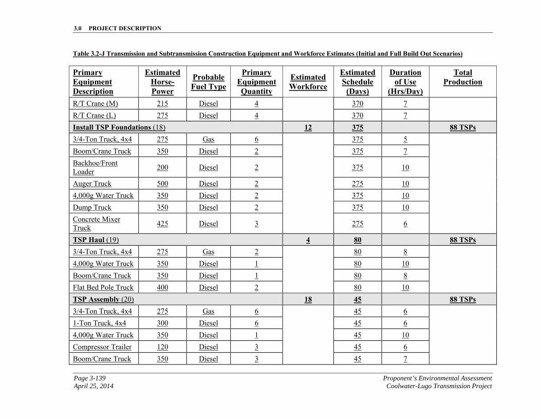
3.0 PROJECT DESCRIPTION
Page 3-139 Proponent’s Environmental Assessment April 25, 2014 Coolwater-Lugo Transmission Project
Table 3.2-J Transmission and Subtransmission Construction Equipment and Workforce Estimates (Initial and Full Build Out Scenarios)
Primary Equipment Description
EstimatedHorse-Power
ProbableFuel Type
Primary Equipment Quantity
Estimated Workforce
EstimatedSchedule
(Days)
Duration of Use
(Hrs/Day)
Total Production
R/T Crane (M) 215 Diesel 4 370 7
R/T Crane (L) 275 Diesel 4 370 7
Install TSP Foundations (18) 12 375 88 TSPs 3/4-Ton Truck, 4x4 275 Gas 6 375 5
Boom/Crane Truck 350 Diesel 2 375 7
Backhoe/Front Loader
200 Diesel 2 375 10
Auger Truck 500 Diesel 2 275 10
4,000g Water Truck 350 Diesel 2 375 10
Dump Truck 350 Diesel 2 375 10
Concrete Mixer Truck
425 Diesel 3 275 6
TSP Haul (19) 4 80 88 TSPs 3/4-Ton Truck, 4x4 275 Gas 2 80 8
4,000g Water Truck 350 Diesel 1 80 10
Boom/Crane Truck 350 Diesel 1 80 8
Flat Bed Pole Truck 400 Diesel 2 80 10
TSP Assembly (20) 18 45 88 TSPs 3/4-Ton Truck, 4x4 275 Gas 6 45 6
1-Ton Truck, 4x4 300 Diesel 6 45 6
4,000g Water Truck 350 Diesel 1 45 10
Compressor Trailer 120 Diesel 3 45 6
Boom/Crane Truck 350 Diesel 3 45 7
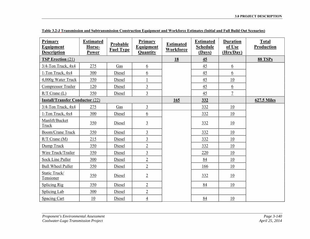
3.0 PROJECT DESCRIPTION
Proponent’s Environmental Assessment Page 3-140 Coolwater-Lugo Transmission Project April 25, 2014
Table 3.2-J Transmission and Subtransmission Construction Equipment and Workforce Estimates (Initial and Full Build Out Scenarios)
Primary Equipment Description
EstimatedHorse-Power
ProbableFuel Type
Primary Equipment Quantity
Estimated Workforce
EstimatedSchedule
(Days)
Duration of Use
(Hrs/Day)
Total Production
TSP Erection (21) 18 45 88 TSPs 3/4-Ton Truck, 4x4 275 Gas 6 45 6
1-Ton Truck, 4x4 300 Diesel 6 45 6
4,000g Water Truck 350 Diesel 1 45 10
Compressor Trailer 120 Diesel 3 45 6
R/T Crane (L) 350 Diesel 3 45 7
Install/Transfer Conductor (22) 165 332 627.5 Miles 3/4-Ton Truck, 4x4 275 Gas 3 332 10
1-Ton Truck, 4x4 300 Diesel 6 332 10
Manlift/Bucket Truck
350 Diesel 3 332 10
Boom/Crane Truck 350 Diesel 3 332 10
R/T Crane (M) 215 Diesel 3 332 10
Dump Truck 350 Diesel 2 332 10
Wire Truck/Trailer 350 Diesel 3 220 10
Sock Line Puller 300 Diesel 2 84 10
Bull Wheel Puller 350 Diesel 2 166 10
Static Truck/ Tensioner
350 Diesel 2 332 10
Splicing Rig 350 Diesel 2 84 10
Splicing Lab 300 Diesel 2
Spacing Cart 10 Diesel 4 84 10
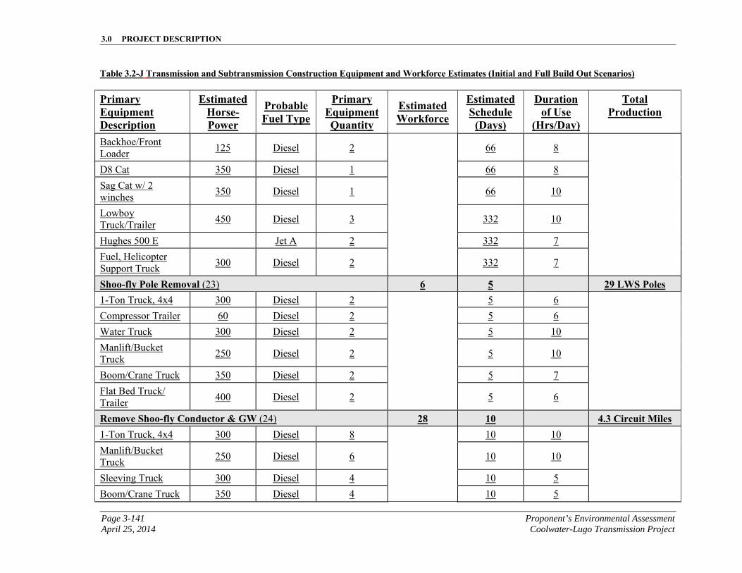
3.0 PROJECT DESCRIPTION
Page 3-141 Proponent’s Environmental Assessment April 25, 2014 Coolwater-Lugo Transmission Project
Table 3.2-J Transmission and Subtransmission Construction Equipment and Workforce Estimates (Initial and Full Build Out Scenarios)
Primary Equipment Description
EstimatedHorse-Power
ProbableFuel Type
Primary Equipment Quantity
Estimated Workforce
EstimatedSchedule
(Days)
Duration of Use
(Hrs/Day)
Total Production
Backhoe/Front Loader
125 Diesel 2 66 8
D8 Cat 350 Diesel 1 66 8
Sag Cat w/ 2 winches
350 Diesel 1 66 10
Lowboy Truck/Trailer
450 Diesel 3 332 10
Hughes 500 E Jet A 2 332 7
Fuel, Helicopter Support Truck
300 Diesel 2 332 7
Shoo-fly Pole Removal (23) 6 5 29 LWS Poles 1-Ton Truck, 4x4 300 Diesel 2 5 6
Compressor Trailer 60 Diesel 2 5 6
Water Truck 300 Diesel 2 5 10
Manlift/Bucket Truck
250 Diesel 2 5 10
Boom/Crane Truck 350 Diesel 2 5 7
Flat Bed Truck/ Trailer
400 Diesel 2 5 6
Remove Shoo-fly Conductor & GW (24) 28 10 4.3 Circuit Miles 1-Ton Truck, 4x4 300 Diesel 8 10 10
Manlift/Bucket Truck
250 Diesel 6 10 10
Sleeving Truck 300 Diesel 4 10 5
Boom/Crane Truck 350 Diesel 4 10 5
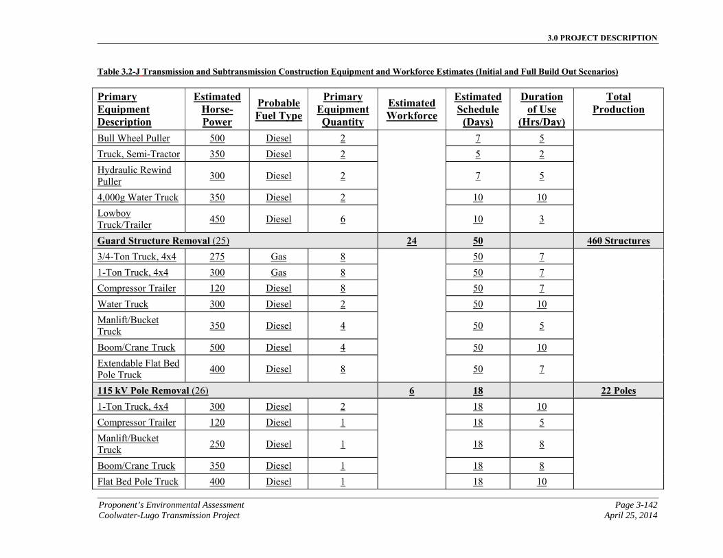
3.0 PROJECT DESCRIPTION
Proponent’s Environmental Assessment Page 3-142 Coolwater-Lugo Transmission Project April 25, 2014
Table 3.2-J Transmission and Subtransmission Construction Equipment and Workforce Estimates (Initial and Full Build Out Scenarios)
Primary Equipment Description
EstimatedHorse-Power
ProbableFuel Type
Primary Equipment Quantity
Estimated Workforce
EstimatedSchedule
(Days)
Duration of Use
(Hrs/Day)
Total Production
Bull Wheel Puller 500 Diesel 2 7 5
Truck, Semi-Tractor 350 Diesel 2 5 2
Hydraulic Rewind Puller
300 Diesel 2 7 5
4,000g Water Truck 350 Diesel 2 10 10
Lowboy Truck/Trailer
450 Diesel 6 10 3
Guard Structure Removal (25) 24 50 460 Structures 3/4-Ton Truck, 4x4 275 Gas 8 50 7
1-Ton Truck, 4x4 300 Gas 8 50 7
Compressor Trailer 120 Diesel 8 50 7
Water Truck 300 Diesel 2 50 10
Manlift/Bucket Truck
350 Diesel 4 50 5
Boom/Crane Truck 500 Diesel 4 50 10
Extendable Flat Bed Pole Truck
400 Diesel 8 50 7
115 kV Pole Removal (26) 6 18 22 Poles 1-Ton Truck, 4x4 300 Diesel 2 18 10
Compressor Trailer 120 Diesel 1 18 5
Manlift/Bucket Truck
250 Diesel 1 18 8
Boom/Crane Truck 350 Diesel 1 18 8
Flat Bed Pole Truck 400 Diesel 1 18 10
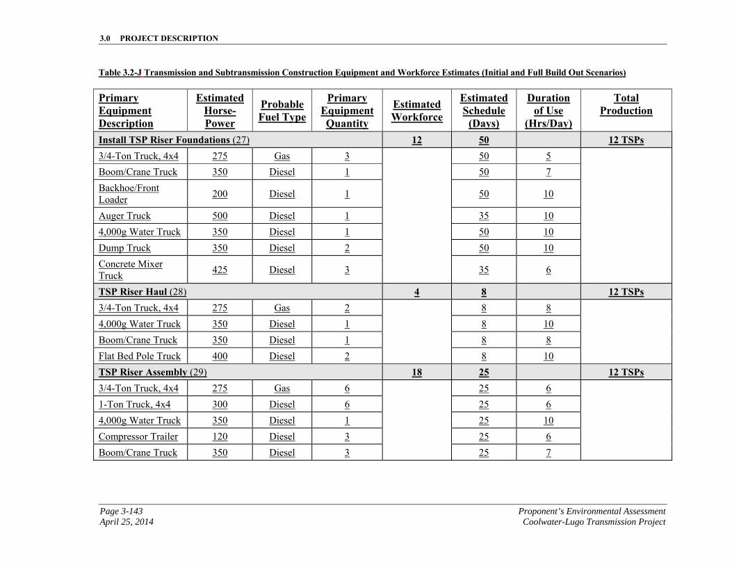
3.0 PROJECT DESCRIPTION
Page 3-143 Proponent’s Environmental Assessment April 25, 2014 Coolwater-Lugo Transmission Project
Table 3.2-J Transmission and Subtransmission Construction Equipment and Workforce Estimates (Initial and Full Build Out Scenarios)
Primary Equipment Description
EstimatedHorse-Power
ProbableFuel Type
Primary Equipment Quantity
Estimated Workforce
EstimatedSchedule
(Days)
Duration of Use
(Hrs/Day)
Total Production
Install TSP Riser Foundations (27) 12 50 12 TSPs 3/4-Ton Truck, 4x4 275 Gas 3 50 5
Boom/Crane Truck 350 Diesel 1 50 7
Backhoe/Front Loader
200 Diesel 1 50 10
Auger Truck 500 Diesel 1 35 10
4,000g Water Truck 350 Diesel 1 50 10
Dump Truck 350 Diesel 2 50 10
Concrete Mixer Truck
425 Diesel 3 35 6
TSP Riser Haul (28) 4 8 12 TSPs 3/4-Ton Truck, 4x4 275 Gas 2 8 8
4,000g Water Truck 350 Diesel 1 8 10
Boom/Crane Truck 350 Diesel 1 8 8
Flat Bed Pole Truck 400 Diesel 2 8 10
TSP Riser Assembly (29) 18 25 12 TSPs 3/4-Ton Truck, 4x4 275 Gas 6 25 6
1-Ton Truck, 4x4 300 Diesel 6 25 6
4,000g Water Truck 350 Diesel 1 25 10
Compressor Trailer 120 Diesel 3 25 6
Boom/Crane Truck 350 Diesel 3 25 7
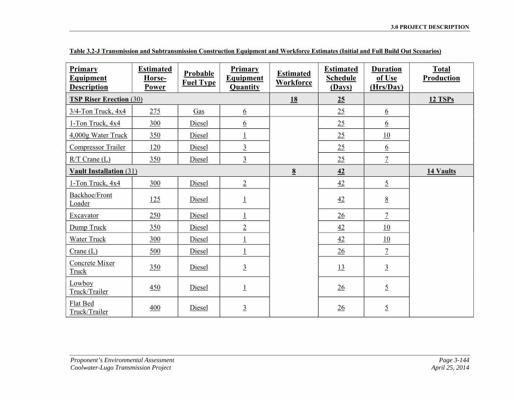
3.0 PROJECT DESCRIPTION
Proponent’s Environmental Assessment Page 3-144 Coolwater-Lugo Transmission Project April 25, 2014
Table 3.2-J Transmission and Subtransmission Construction Equipment and Workforce Estimates (Initial and Full Build Out Scenarios)
Primary Equipment Description
EstimatedHorse-Power
ProbableFuel Type
Primary Equipment Quantity
Estimated Workforce
EstimatedSchedule
(Days)
Duration of Use
(Hrs/Day)
Total Production
TSP Riser Erection (30) 18 25 12 TSPs
3/4-Ton Truck, 4x4 275 Gas 6 25 6
1-Ton Truck, 4x4 300 Diesel 6 25 6
4,000g Water Truck 350 Diesel 1 25 10
Compressor Trailer 120 Diesel 3 25 6
R/T Crane (L) 350 Diesel 3 25 7
Vault Installation (31) 8 42 14 Vaults
1-Ton Truck, 4x4 300 Diesel 2 42 5
Backhoe/Front Loader
125 Diesel 1 42 8
Excavator 250 Diesel 1 26 7
Dump Truck 350 Diesel 2 42 10
Water Truck 300 Diesel 1 42 10
Crane (L) 500 Diesel 1 26 7
Concrete Mixer Truck
350 Diesel 3 13 3
Lowboy Truck/Trailer
450 Diesel 1 26 5
Flat Bed Truck/Trailer
400 Diesel 3 26 5
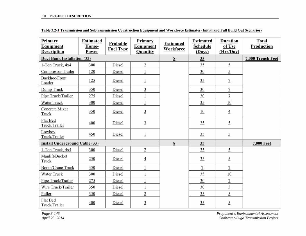
3.0 PROJECT DESCRIPTION
Page 3-145 Proponent’s Environmental Assessment April 25, 2014 Coolwater-Lugo Transmission Project
Table 3.2-J Transmission and Subtransmission Construction Equipment and Workforce Estimates (Initial and Full Build Out Scenarios)
Primary Equipment Description
EstimatedHorse-Power
ProbableFuel Type
Primary Equipment Quantity
Estimated Workforce
EstimatedSchedule
(Days)
Duration of Use
(Hrs/Day)
Total Production
Duct Bank Installation (32) 8 35 7,000 Trench Feet 1-Ton Truck, 4x4 300 Diesel 2 35 5
Compressor Trailer 120 Diesel 1 30 5
Backhoe/Front Loader
125 Diesel 1 35 7
Dump Truck 350 Diesel 3 30 7
Pipe Truck/Trailer 275 Diesel 1 30 7
Water Truck 300 Diesel 1 35 10
Concrete Mixer Truck
350 Diesel 3 10 4
Flat Bed Truck/Trailer
400 Diesel 3 35 5
Lowboy Truck/Trailer
450 Diesel 1 35 5
Install Underground Cable (33) 8 35 7,000 Feet 1-Ton Truck, 4x4 300 Diesel 2 35 5
Manlift/Bucket Truck
250 Diesel 4 35 5
Boom/Crane Truck 350 Diesel 1 7 7
Water Truck 300 Diesel 1 35 10
Pipe Truck/Trailer 275 Diesel 1 30 7
Wire Truck/Trailer 350 Diesel 1 30 5
Puller 350 Diesel 2 35 5
Flat Bed Truck/Trailer
400 Diesel 3 35 5
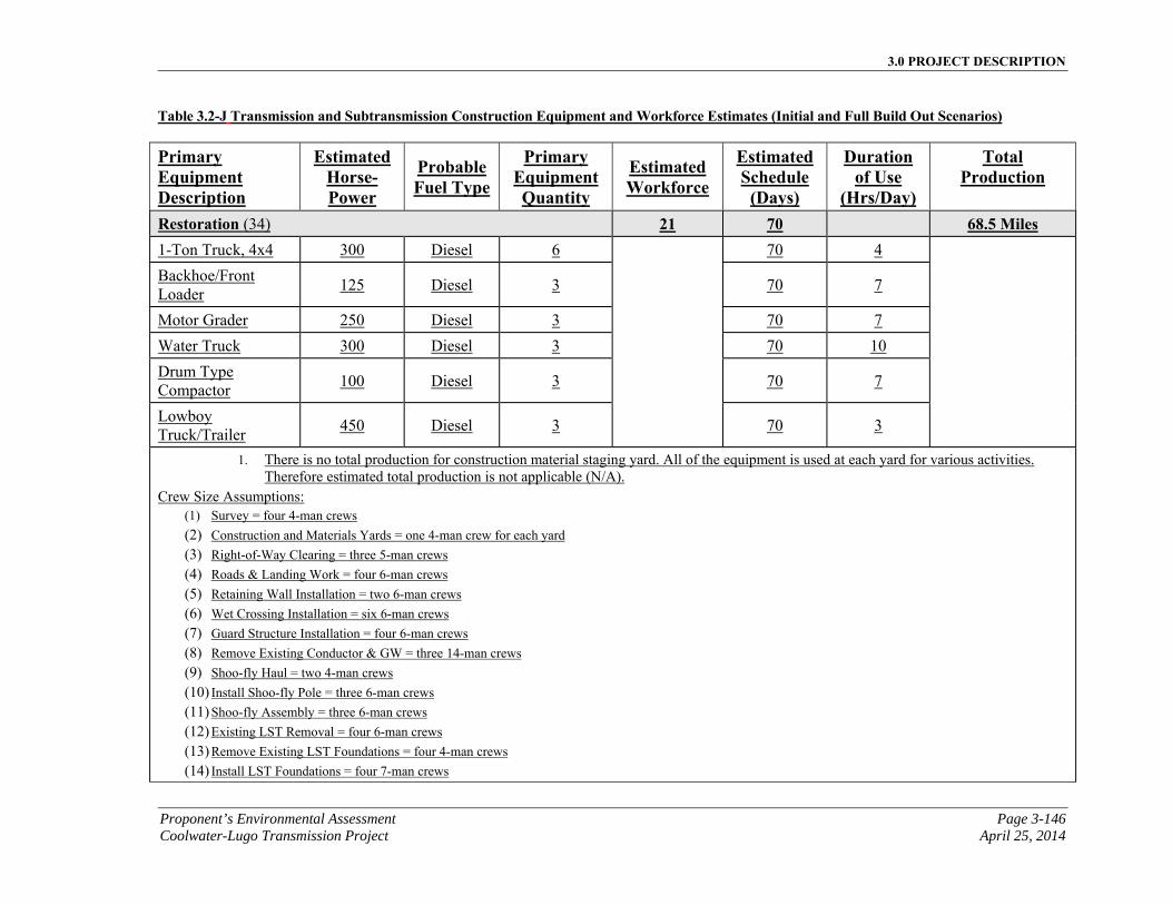
3.0 PROJECT DESCRIPTION
Proponent’s Environmental Assessment Page 3-146 Coolwater-Lugo Transmission Project April 25, 2014
Table 3.2-J Transmission and Subtransmission Construction Equipment and Workforce Estimates (Initial and Full Build Out Scenarios)
Primary Equipment Description
EstimatedHorse-Power
ProbableFuel Type
Primary Equipment Quantity
Estimated Workforce
EstimatedSchedule
(Days)
Duration of Use
(Hrs/Day)
Total Production
Restoration (34) 21 70 68.5 Miles 1-Ton Truck, 4x4 300 Diesel 6 70 4
Backhoe/Front Loader
125 Diesel 3 70 7
Motor Grader 250 Diesel 3 70 7
Water Truck 300 Diesel 3 70 10
Drum Type Compactor
100 Diesel 3 70 7
Lowboy Truck/Trailer
450 Diesel 3 70 3
1. There is no total production for construction material staging yard. All of the equipment is used at each yard for various activities. Therefore estimated total production is not applicable (N/A).
Crew Size Assumptions: (1) Survey = four 4-man crews
(2) Construction and Materials Yards = one 4-man crew for each yard (3) Right-of-Way Clearing = three 5-man crews (4) Roads & Landing Work = four 6-man crews (5) Retaining Wall Installation = two 6-man crews (6) Wet Crossing Installation = six 6-man crews (7) Guard Structure Installation = four 6-man crews (8) Remove Existing Conductor & GW = three 14-man crews (9) Shoo-fly Haul = two 4-man crews (10) Install Shoo-fly Pole = three 6-man crews (11) Shoo-fly Assembly = three 6-man crews (12) Existing LST Removal = four 6-man crews (13) Remove Existing LST Foundations = four 4-man crews (14) Install LST Foundations = four 7-man crews
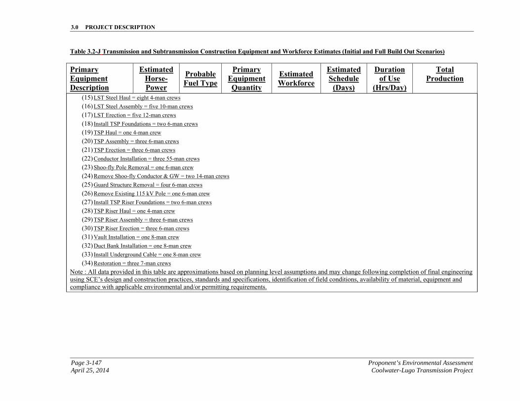
3.0 PROJECT DESCRIPTION
Page 3-147 Proponent’s Environmental Assessment April 25, 2014 Coolwater-Lugo Transmission Project
Table 3.2-J Transmission and Subtransmission Construction Equipment and Workforce Estimates (Initial and Full Build Out Scenarios)
Primary Equipment Description
EstimatedHorse-Power
ProbableFuel Type
Primary Equipment Quantity
Estimated Workforce
EstimatedSchedule
(Days)
Duration of Use
(Hrs/Day)
Total Production
(15) LST Steel Haul = eight 4-man crews (16) LST Steel Assembly = five 10-man crews (17) LST Erection = five 12-man crews (18) Install TSP Foundations = two 6-man crews (19) TSP Haul = one 4-man crew (20) TSP Assembly = three 6-man crews (21) TSP Erection = three 6-man crews (22) Conductor Installation = three 55-man crews (23) Shoo-fly Pole Removal = one 6-man crew (24) Remove Shoo-fly Conductor & GW = two 14-man crews (25) Guard Structure Removal = four 6-man crews (26) Remove Existing 115 kV Pole = one 6-man crew (27) Install TSP Riser Foundations = two 6-man crews (28) TSP Riser Haul = one 4-man crew (29) TSP Riser Assembly = three 6-man crews (30) TSP Riser Erection = three 6-man crews (31) Vault Installation = one 8-man crew (32) Duct Bank Installation = one 8-man crew (33) Install Underground Cable = one 8-man crew (34) Restoration = three 7-man crews
Note : All data provided in this table are approximations based on planning level assumptions and may change following completion of final engineering using SCE’s design and construction practices, standards and specifications, identification of field conditions, availability of material, equipment and compliance with applicable environmental and/or permitting requirements.
3.0 PROJECT DESCRIPTION
Proponent’s Environmental Assessment Page 3-148 Coolwater-Lugo Transmission Project April 25, 2014
This page is intentionally blank.
3.0 PROJECT DESCRIPTION
Page 3-149 Proponent’s Environmental Assessment April 25, 2014 Coolwater-Lugo Transmission Project
Fiber-optic system construction at existing substations would include the installation of new equipment racks, power cables to the new racks from the DC power board, fiber-optic patch panels, termination of fiber-optic cable on these panels, installation of lightwave equipment, microwave equipment, channel bank equipment, and the cabling out of this equipment to panels, jackfields, or main distribution frames (“MDF”), and additional miscellaneous telecommunication equipment as needed.
Work related to existing communication sites would include path re-alignment of the antennae dish at the Ord Mountain Communication Site and cross connects at one or more additional existing communication sites.
3.2.5.2 Microwave Installation
All tower, antenna, and waveguide material would be delivered by truck and would be staged within a laydown area at or near Coolwater Switchyard. As described in Section 3.1.6, Telecommunication Description, a new 150-foot tall lattice steel microwave tower and foundation would be constructed in support of the new 220 kV switchyard and 115 kV switchyard MEERs. The foundation dimensions would be approximately 35 feet long by 35 feet wide. The foundation process would start with drilling holes in the ground using an excavator with the appropriate diameter auger. The spoils produced from drilling would be used as described in Section 3.7, Reusable, Recyclable, and Waste Material Management. Following excavation for the foundation, reinforcing steel and anchor bolts would be installed in the hole and the concrete would then be placed. Once the concrete is sufficiently cured, crews would commence erection of the tower. Sections of the tower would be assembled on the ground and lifted into place by means of a crane. If the tower is to be built higher than the crane can reach, then a gin-pole would be used. Once the tower is complete, antenna(s) and waveguide would be installed on the tower using a crane or gin-pole as appropriate. SCE anticipates using one or more of the possible locations listed in Table 3.2-A, Potential Staging Yard Locations, as the staging yard(s) for equipment.
3.2.5.3 Fiber-Optic Cable Installation
Overhead fiber-optic cable would be installed on overhead structures as described in Section 3.2.3.9, Wire Stringing.
New overhead cable would be installed on a combination of existing and new wood and LWS pole structures from Apple Valley Substation to Proposed Desert View Substation and from Gale Substation to Pisgah Substation, as shown in Figure 3.1-F, Proposed Telecommunication Route.
OPGW would be installed on the proposed transmission towers. At transmission pulling locations, splice boxes would be installed on 220 kV or 500 kV tower structures in order to splice the fiber strands together.
3.0 PROJECT DESCRIPTION
Proponent’s Environmental Assessment Page 3-150 Coolwater-Lugo Transmission Project April 25, 2014
3.2.5.4 Underground Fiber-Optic Cable Installation
Where the Proposed Transmission Line crosses underneath other existing transmission lines, the fiber-optic cable would be undergrounded for operational reliability. Undergrounding would require conduits and pull boxes at each end of the tower.
The fiber-optic cable would be installed throughout the length of the underground conduit and structures through an innerduct which provides protection and identification for the cable. First the innerduct would be pulled in the conduit from structure to structure using a pull rope and pulling machine or truck mounted hydraulic capstan. Then the fiber-optic cable would be pulled inside the innerduct using the same procedure.
Undergrounding would require excavation for installation of manholes and vaults or pull boxes at each of the ends, as well as underground conduit approximately 5-inches in diameter. New underground conduit and structures would typically be installed with a backhoe. The trench would be excavated to approximately 1 foot wide and a minimum of approximately 3 feet deep. PVC conduit would be placed in the trench and covered with a minimum of 3 inches of concrete slurry then backfilled and compacted. Underground conduits are 5 inch diameter. For manholes and pull boxes, a hole is excavated approximately 8 feet deep by approximately 6 feet long by approximately 6 feet wide. The manhole or pull box would be lowered into place, connected to the conduits, and the hole would be backfilled with concrete slurry. Splice boxes would also be required on the tower structures at each of the ends.
SCE would install the fiber-optic cables at the pull boxes, splice the cable segments at each tower, where it would transition from underground to overhead. A splice crew would conduct splicing operations at each location and continue until all splicing is completed.
Underground fiber-optic cable systems would be installed at the following locations: SCE’s Coolwater Switchyard; transmission line crossings at LADWP corridor, near SCE’s existing ROW southwest of the intersection of Haynes Road and SR-247, and by SR-18; at existing Lugo Substation; and, just outside of Proposed Desert View Substation. At Lugo Substation, Coolwater Switchyard, and Proposed Desert View Substation, the fiber-optic strands would be separated from the ground wire at the last tower structure outside the substation perimeter. At this tower location, telecommunications would install a splice case on the tower leg, and an underground vault. From this vault an underground conduit would be constructed in the general direction of the substation or switchyard perimeter and connect to underground conduit or a pull box just inside, or just outside, the substation fence or wall.
3.2.5.5 Wood Pole Installation
New wood poles would be installed between the Proposed Desert View Substation and Del Oro Road. Each wood pole would require a hole to be excavated using either an auger, backhoe, or with hand tools. Excavated material would be used as described in Section 3.7, Reusable, Recyclable, and Waste Material Management. The wood poles
3.0 PROJECT DESCRIPTION
Page 3-151 Proponent’s Environmental Assessment April 25, 2014 Coolwater-Lugo Transmission Project
would be placed in temporary laydown areas at each pole location. While on the ground, the wood poles may be configured (if not preconfigured) with the necessary cross arms, and fiber-stringing hardware before being set in place.
Each wood pole would be approximately 24 inches in diameter and about 35 feet in total length. The pole would be inserted into a hole which is dug approximately 6 feet in depth, typically by a line truck with an attached boom. The hole would be backfilled, and the pole would rise approximately 30 feet from ground level. Crossarms and supporting hardware would be installed on the poles to support the ADSS fiber-optic cable. Down guys would be attached to anchors as needed.
3.2.5.6 Wood Pole Replacements
To facilitate the construction and installation of new telecommunication infrastructure on existing wood distribution poles, approximately 14 poles have been identified to be replaced.
The replacement of a typical existing electrical distribution wood pole would be done while the conductor is energized. In some cases where isolation switches are available, the pole line could be de-energized. Prior to removal of the existing pole, the new pole would be installed in proximity to the old pole to be replaced. A hole would typically be dug using a digger truck or possibly hand-dug if inaccessible by truck. The new pole would then be set in the hole and backfilled with soil from the excavation. The area around the pole would then be tamped for compaction. Appropriate components such as cross arms, insulators, and down guys would be installed on the new pole to accommodate the distribution circuit conductor. The existing distribution conductors and telecommunication lines (where applicable) would be transferred to the new structures. The distribution circuit would then be detached from the old pole. The components on the old existing pole would be completely removed. Finally the old pole would be extracted from the ground or cut at a lower level if a third party's facilities remain attached. After the original pole is removed, the residual hole would then be filled in and compacted appropriately. Any holes left from removing the poles would be backfilled with spoils that may be available as a result of the excavation for new poles and/or by using imported fill as needed.
3.2.5.7 Road Access for Telecommunication Installation
Existing roads within the vicinity of the Proposed Project and roads to be constructed to access the Proposed Transmission Route would be adequate to provide access for installation and ongoing maintenance of the Proposed Telecommunication Facilities.
3.2.5.8 Telecommunication System Land Disturbance
Table 3.2-J, Telecommunication System Estimated Land Disturbance, provides a summary of the land disturbance estimates associated with the Proposed Telecommunication Systems associated with the Proposed Project.

3.0 PROJECT DESCRIPTION
Proponent’s Environmental Assessment Page 3-152 Coolwater-Lugo Transmission Project April 25, 2014
This page is intentionally blank.
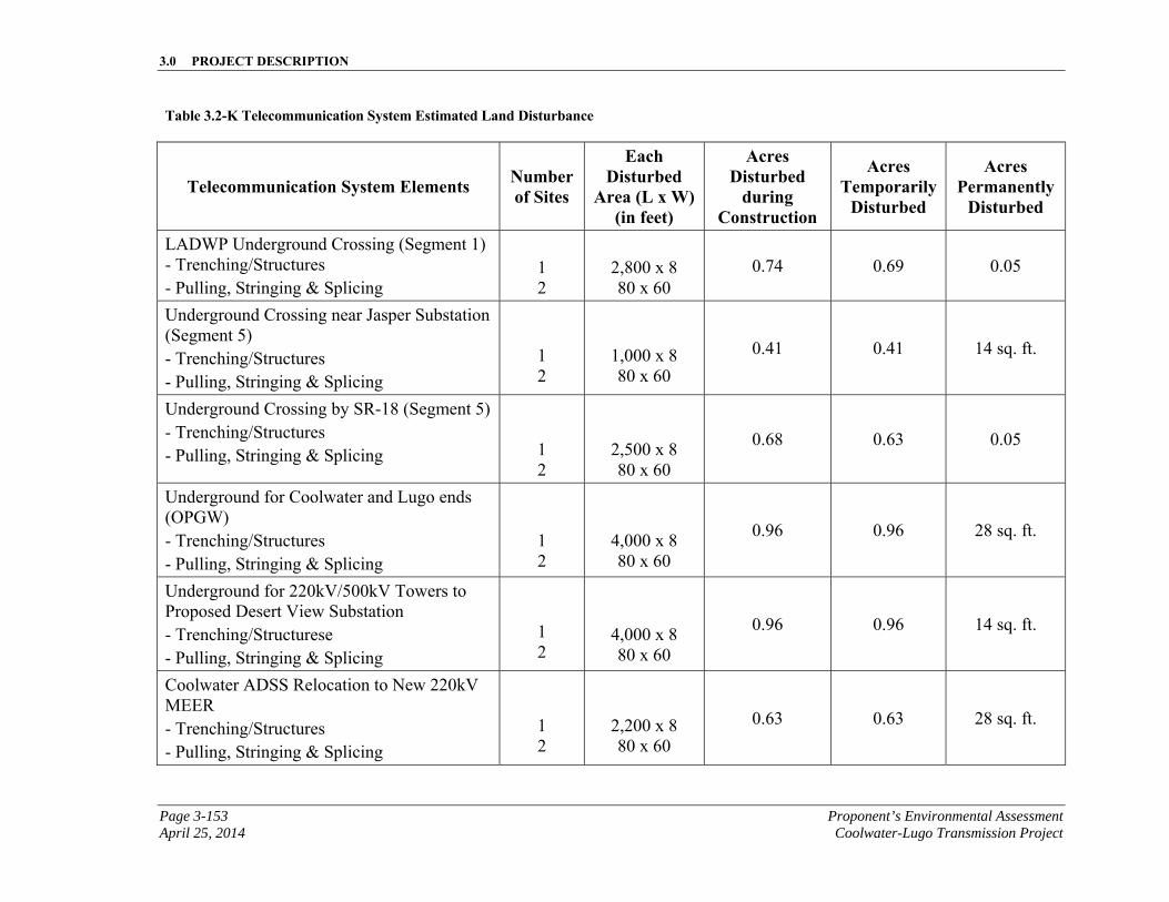
3.0 PROJECT DESCRIPTION
Page 3-153 Proponent’s Environmental Assessment April 25, 2014 Coolwater-Lugo Transmission Project
Table 3.2-K Telecommunication System Estimated Land Disturbance
Telecommunication System Elements Number of Sites
Each Disturbed
Area (L x W) (in feet)
Acres Disturbed
during Construction
Acres Temporarily
Disturbed
Acres Permanently
Disturbed
LADWP Underground Crossing (Segment 1) - Trenching/Structures - Pulling, Stringing & Splicing
1 2
2,800 x 8 80 x 60
0.74 0.69 0.05
Underground Crossing near Jasper Substation (Segment 5) - Trenching/Structures - Pulling, Stringing & Splicing
1 2
1,000 x 8 80 x 60
0.41 0.41 14 sq. ft.
Underground Crossing by SR-18 (Segment 5) - Trenching/Structures - Pulling, Stringing & Splicing
1 2
2,500 x 8 80 x 60
0.68 0.63 0.05
Underground for Coolwater and Lugo ends (OPGW) - Trenching/Structures - Pulling, Stringing & Splicing
1 2
4,000 x 8 80 x 60
0.96 0.96 28 sq. ft.
Underground for 220kV/500kV Towers to Proposed Desert View Substation - Trenching/Structurese - Pulling, Stringing & Splicing
1 2
4,000 x 8 80 x 60
0.96 0.96 14 sq. ft.
Coolwater ADSS Relocation to New 220kV MEER - Trenching/Structures - Pulling, Stringing & Splicing
1 2
2,200 x 8 80 x 60
0.63 0.63 28 sq. ft.
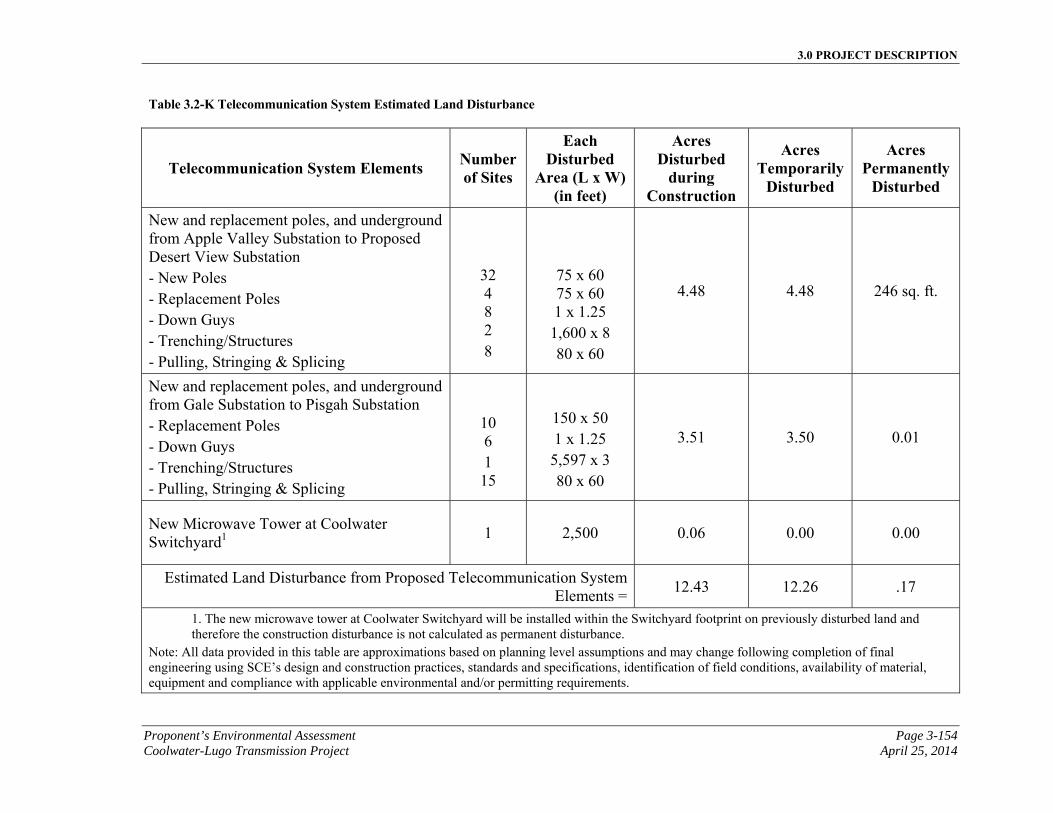
3.0 PROJECT DESCRIPTION
Proponent’s Environmental Assessment Page 3-154 Coolwater-Lugo Transmission Project April 25, 2014
Table 3.2-K Telecommunication System Estimated Land Disturbance
Telecommunication System Elements Number of Sites
Each Disturbed
Area (L x W) (in feet)
Acres Disturbed
during Construction
Acres Temporarily
Disturbed
Acres Permanently
Disturbed
New and replacement poles, and underground from Apple Valley Substation to Proposed Desert View Substation - New Poles - Replacement Poles - Down Guys - Trenching/Structures - Pulling, Stringing & Splicing
32 4 8 2 8
75 x 60 75 x 60 1 x 1.25 1,600 x 8 80 x 60
4.48 4.48 246 sq. ft.
New and replacement poles, and underground from Gale Substation to Pisgah Substation - Replacement Poles - Down Guys - Trenching/Structures - Pulling, Stringing & Splicing
10 6 1 15
150 x 50 1 x 1.25 5,597 x 3 80 x 60
3.51 3.50 0.01
New Microwave Tower at Coolwater Switchyard1
1 2,500 0.06 0.00 0.00
Estimated Land Disturbance from Proposed Telecommunication System Elements =
12.43 12.26 .17
1. The new microwave tower at Coolwater Switchyard will be installed within the Switchyard footprint on previously disturbed land and therefore the construction disturbance is not calculated as permanent disturbance.
Note: All data provided in this table are approximations based on planning level assumptions and may change following completion of final engineering using SCE’s design and construction practices, standards and specifications, identification of field conditions, availability of material, equipment and compliance with applicable environmental and/or permitting requirements.
3.0 PROJECT DESCRIPTION
Page 3-155 Proponent’s Environmental Assessment April 25, 2014 Coolwater-Lugo Transmission Project
3.2.5.9 Telecommunication System Construction Equipment and Workforce Estimates
The estimated elements, materials and number of personnel and equipment required for construction of the Proposed Telecommunication Systems are summarized in Table 3.2-K, Telecommunication System Construction Equipment and Workforce Estimates.
3.2.6 Distribution for Station Light & Power Installation
Approximately 500 feet of a new 12 kV overhead distribution line section would be installed to supply substation light and power to the Proposed Desert View Substation as part of the minimum or initial build out. The new line section would be connected to the existing circuit on the south side of Desert View Road, and extend north, perpendicular to the existing 12 kV distribution circuit towards the south side of the proposed substation perimeter. The circuit would then be transitioned underground, just outside the substation and enter the substation underground.
3.2.6.1 Overhead Distribution Structure Assembly and Installation
Structural components of the distribution equipment would be shipped by truck to the construction material yards and then trucked to the work location. The wood poles and associated equipment would be installed between the south side of Proposed Desert View Substation and the existing circuits on the south side of Desert View Road. Installation of wood poles would be the same as described for Telecommunication in Section 3.2.5.5, Wood Pole Installation. Wood guy stub poles would be installed similarly to wood poles. Ground disturbance would generally be limited to the construction areas. The ground disturbance for each pole installation would typically be approximately 5 square feet per pole and 1 square foot per pole anchor.
The installation of a typical new electrical distribution pole line section would be done before the conductor is energized. Isolation switches where available would be used to de-energize existing circuitry before the newly constructed distribution circuitry is attached to the existing distribution infrastructure. Each new wood pole would be approximately 45-feet to 55-feet high and 7-feet to 14-feet wide. For each new wood pole, a hole approximately 2-feet wide would be excavated, typically using a digger truck or possibly hand-dug if inaccessible by truck. The new pole would then be set in the hole and backfilled with soil which would be tamped for compaction. Appropriate components such as cross arms, insulators and down guys would be installed on the new pole to accommodate the distribution circuit conductor. The new distribution conductors would then be attached to the new structure. Once the construction is fully completed and cleared for operation, electrical system operations would be performed to energize the newly constructed distribution line section.

3.0 PROJECT DESCRIPTION
Proponent’s Environmental Assessment Page 3-156 Coolwater-Lugo Transmission Project April 25, 2014
This page is intentionally blank.
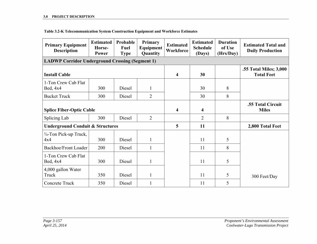
3.0 PROJECT DESCRIPTION
Page 3-157 Proponent’s Environmental Assessment April 25, 2014 Coolwater-Lugo Transmission Project
Table 3.2-K Telecommunication System Construction Equipment and Workforce Estimates
Primary Equipment Description
Estimated Horse-Power
Probable Fuel Type
Primary Equipment Quantity
Estimated Workforce
Estimated Schedule
(Days)
Duration of Use
(Hrs/Day)
Estimated Total and Daily Production
LADWP Corridor Underground Crossing (Segment 1)
Install Cable 4 30 .55 Total Miles; 3,000
Total Feet
1-Ton Crew Cab Flat Bed, 4x4 300 Diesel 1 30 8
Bucket Truck 300 Diesel 2 30 8
Splice Fiber-Optic Cable 4 4 .55 Total Circuit
Miles
Splicing Lab 300 Diesel 2 2 8
Underground Conduit & Structures 5 11 2,800 Total Feet
¾-Ton Pick-up Truck, 4x4 300 Diesel 1
11 5
300 Feet/Day
Backhoe/Front Loader 200 Diesel 1 11 8
1-Ton Crew Cab Flat Bed, 4x4 300 Diesel 1 11 5
4,000 gallon Water Truck 350 Diesel 1 11 5
Concrete Truck 350 Diesel 1 11 5
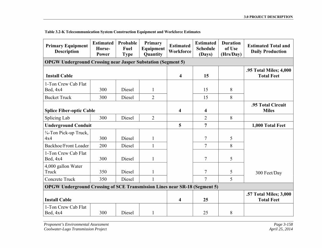
3.0 PROJECT DESCRIPTION
Proponent’s Environmental Assessment Page 3-158 Coolwater-Lugo Transmission Project April 25, 2014
Table 3.2-K Telecommunication System Construction Equipment and Workforce Estimates
Primary Equipment Description
Estimated Horse-Power
Probable Fuel Type
Primary Equipment Quantity
Estimated Workforce
Estimated Schedule
(Days)
Duration of Use
(Hrs/Day)
Estimated Total and Daily Production
OPGW Underground Crossing near Jasper Substation (Segment 5)
Install Cable 4 15 .95 Total Miles; 4,000
Total Feet
1-Ton Crew Cab Flat Bed, 4x4 300 Diesel 1 15 8
Bucket Truck 300 Diesel 2 15 8
Splice Fiber-optic Cable 4 4 .95 Total Circuit
Miles Splicing Lab 300 Diesel 2 2 8
Underground Conduit 5 7 1,000 Total Feet ¾-Ton Pick-up Truck, 4x4 300 Diesel 1 7 5
300 Feet/Day
Backhoe/Front Loader 200 Diesel 1 7 8
1-Ton Crew Cab Flat Bed, 4x4 300 Diesel 1 7 5
4,000 gallon Water Truck 350 Diesel 1 7 5
Concrete Truck 350 Diesel 1 7 5
OPGW Underground Crossing of SCE Transmission Lines near SR-18 (Segment 5)
Install Cable 4 25 .57 Total Miles; 3,000
Total Feet 1-Ton Crew Cab Flat Bed, 4x4 300 Diesel 1 25 8
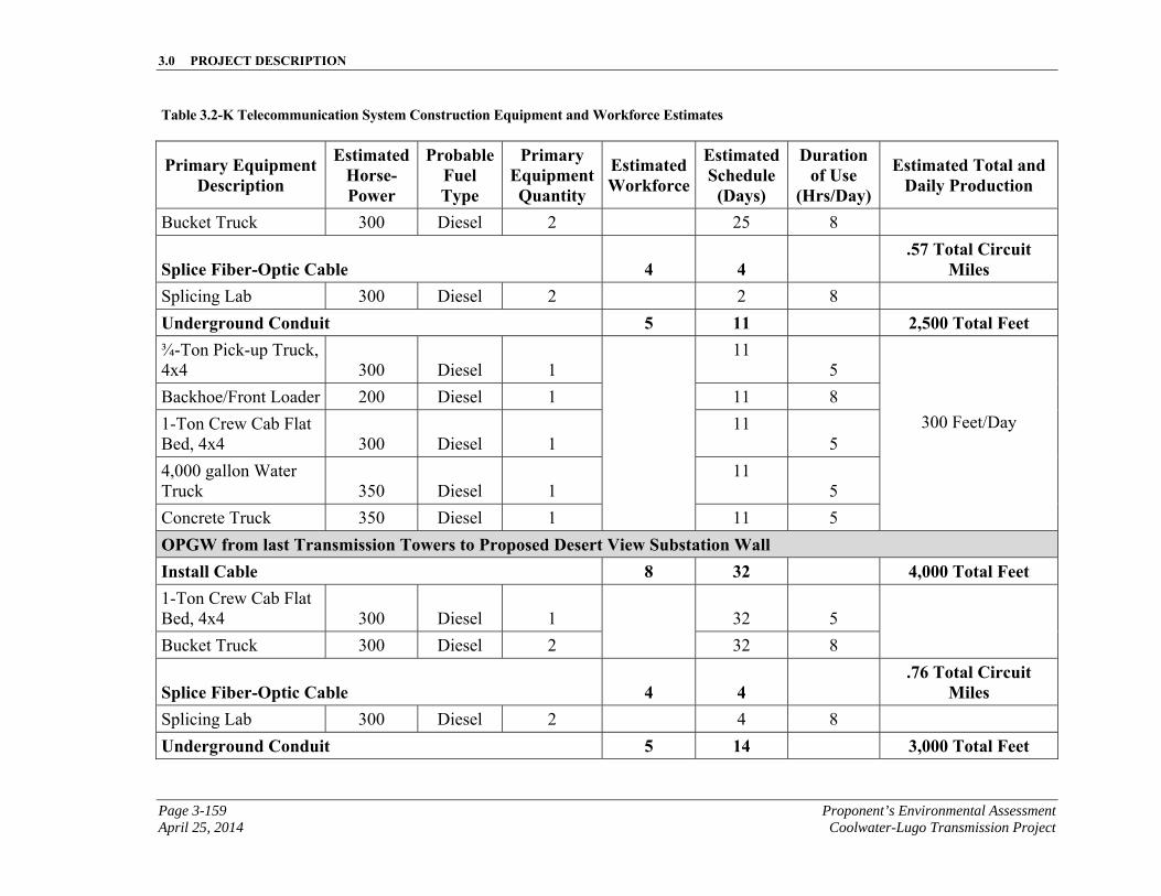
3.0 PROJECT DESCRIPTION
Page 3-159 Proponent’s Environmental Assessment April 25, 2014 Coolwater-Lugo Transmission Project
Table 3.2-K Telecommunication System Construction Equipment and Workforce Estimates
Primary Equipment Description
Estimated Horse-Power
Probable Fuel Type
Primary Equipment Quantity
Estimated Workforce
Estimated Schedule
(Days)
Duration of Use
(Hrs/Day)
Estimated Total and Daily Production
Bucket Truck 300 Diesel 2 25 8
Splice Fiber-Optic Cable 4 4 .57 Total Circuit
Miles Splicing Lab 300 Diesel 2 2 8
Underground Conduit 5 11 2,500 Total Feet ¾-Ton Pick-up Truck, 4x4 300 Diesel 1
11 5
300 Feet/Day
Backhoe/Front Loader 200 Diesel 1 11 8
1-Ton Crew Cab Flat Bed, 4x4 300 Diesel 1
11 5
4,000 gallon Water Truck 350 Diesel 1
11 5
Concrete Truck 350 Diesel 1 11 5
OPGW from last Transmission Towers to Proposed Desert View Substation Wall Install Cable 8 32 4,000 Total Feet 1-Ton Crew Cab Flat Bed, 4x4 300 Diesel 1 32 5
Bucket Truck 300 Diesel 2 32 8
Splice Fiber-Optic Cable 4 4 .76 Total Circuit
Miles Splicing Lab 300 Diesel 2 4 8
Underground Conduit 5 14 3,000 Total Feet
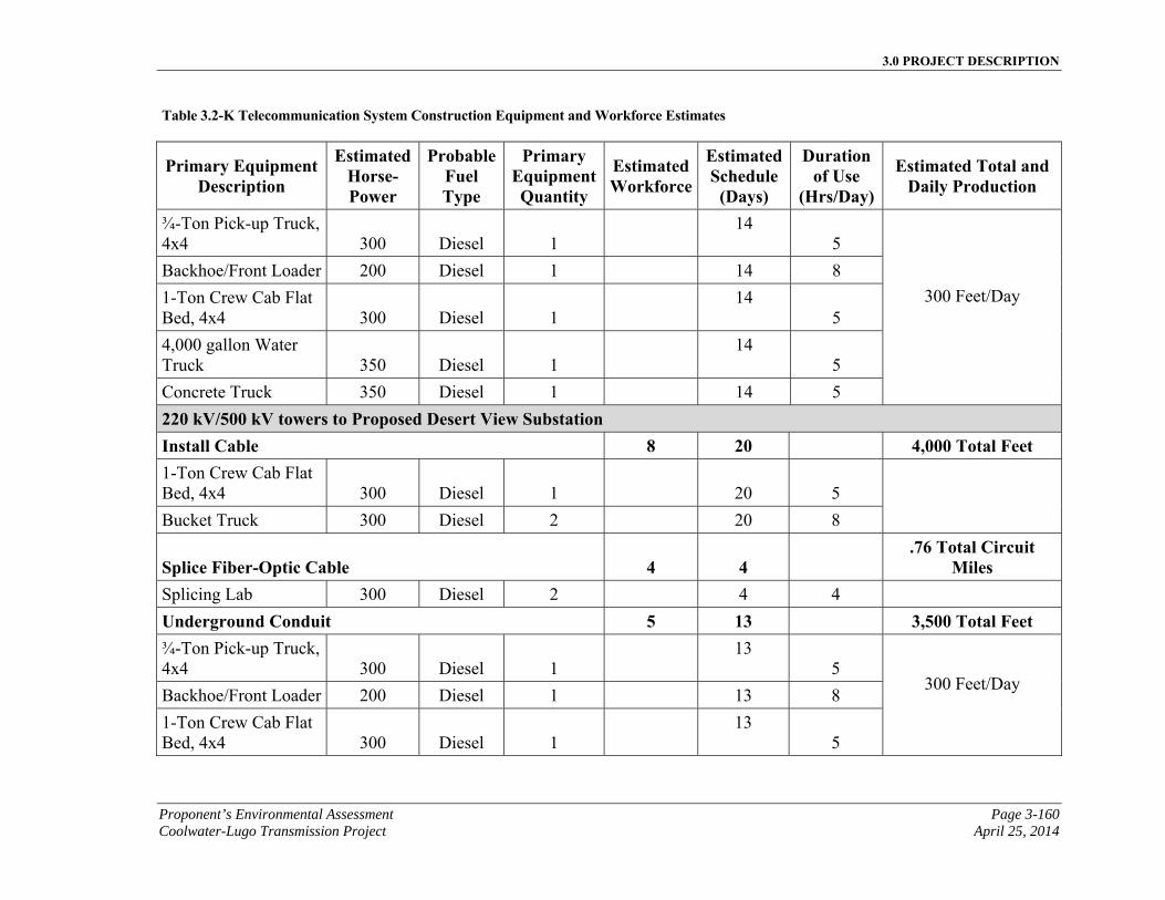
3.0 PROJECT DESCRIPTION
Proponent’s Environmental Assessment Page 3-160 Coolwater-Lugo Transmission Project April 25, 2014
Table 3.2-K Telecommunication System Construction Equipment and Workforce Estimates
Primary Equipment Description
Estimated Horse-Power
Probable Fuel Type
Primary Equipment Quantity
Estimated Workforce
Estimated Schedule
(Days)
Duration of Use
(Hrs/Day)
Estimated Total and Daily Production
¾-Ton Pick-up Truck, 4x4 300 Diesel 1
14 5
300 Feet/Day
Backhoe/Front Loader 200 Diesel 1 14 8
1-Ton Crew Cab Flat Bed, 4x4 300 Diesel 1
14 5
4,000 gallon Water Truck 350 Diesel 1
14 5
Concrete Truck 350 Diesel 1 14 5
220 kV/500 kV towers to Proposed Desert View Substation Install Cable 8 20 4,000 Total Feet 1-Ton Crew Cab Flat Bed, 4x4 300 Diesel 1 20 5
Bucket Truck 300 Diesel 2 20 8
Splice Fiber-Optic Cable 4 4 .76 Total Circuit
Miles Splicing Lab 300 Diesel 2 4 4
Underground Conduit 5 13 3,500 Total Feet ¾-Ton Pick-up Truck, 4x4 300 Diesel 1
13 5
300 Feet/Day
Backhoe/Front Loader 200 Diesel 1 13 8
1-Ton Crew Cab Flat Bed, 4x4 300 Diesel 1
13 5
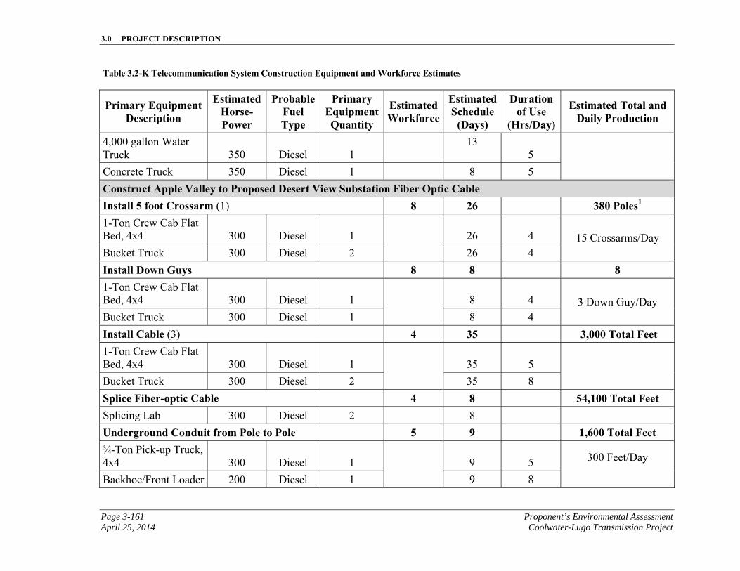
3.0 PROJECT DESCRIPTION
Page 3-161 Proponent’s Environmental Assessment April 25, 2014 Coolwater-Lugo Transmission Project
Table 3.2-K Telecommunication System Construction Equipment and Workforce Estimates
Primary Equipment Description
Estimated Horse-Power
Probable Fuel Type
Primary Equipment Quantity
Estimated Workforce
Estimated Schedule
(Days)
Duration of Use
(Hrs/Day)
Estimated Total and Daily Production
4,000 gallon Water Truck 350 Diesel 1
13 5
Concrete Truck 350 Diesel 1 8 5
Construct Apple Valley to Proposed Desert View Substation Fiber Optic Cable Install 5 foot Crossarm (1) 8 26 380 Poles1 1-Ton Crew Cab Flat Bed, 4x4 300 Diesel 1 26 4 15 Crossarms/Day Bucket Truck 300 Diesel 2 26 4
Install Down Guys 8 8 8 1-Ton Crew Cab Flat Bed, 4x4 300 Diesel 1
8 4 3 Down Guy/Day Bucket Truck 300 Diesel 1 8 4
Install Cable (3) 4 35 3,000 Total Feet 1-Ton Crew Cab Flat Bed, 4x4 300 Diesel 1 35 5
Bucket Truck 300 Diesel 2 35 8
Splice Fiber-optic Cable 4 8 54,100 Total Feet Splicing Lab 300 Diesel 2 8
Underground Conduit from Pole to Pole 5 9 1,600 Total Feet ¾-Ton Pick-up Truck, 4x4 300 Diesel 1
9 5 300 Feet/Day
Backhoe/Front Loader 200 Diesel 1 9 8
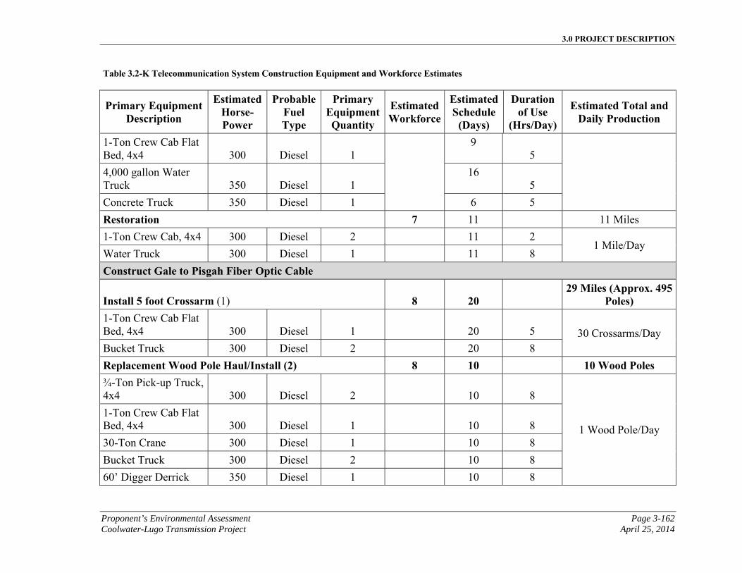
3.0 PROJECT DESCRIPTION
Proponent’s Environmental Assessment Page 3-162 Coolwater-Lugo Transmission Project April 25, 2014
Table 3.2-K Telecommunication System Construction Equipment and Workforce Estimates
Primary Equipment Description
Estimated Horse-Power
Probable Fuel Type
Primary Equipment Quantity
Estimated Workforce
Estimated Schedule
(Days)
Duration of Use
(Hrs/Day)
Estimated Total and Daily Production
1-Ton Crew Cab Flat Bed, 4x4 300 Diesel 1
9 5
4,000 gallon Water Truck 350 Diesel 1
16 5
Concrete Truck 350 Diesel 1 6 5
Restoration 7 11 11 Miles
1-Ton Crew Cab, 4x4 300 Diesel 2 11 2 1 Mile/Day
Water Truck 300 Diesel 1 11 8
Construct Gale to Pisgah Fiber Optic Cable
Install 5 foot Crossarm (1) 8 20 29 Miles (Approx. 495
Poles) 1-Ton Crew Cab Flat Bed, 4x4 300 Diesel 1 20 5 30 Crossarms/Day Bucket Truck 300 Diesel 2 20 8
Replacement Wood Pole Haul/Install (2) 8 10 10 Wood Poles ¾-Ton Pick-up Truck, 4x4 300 Diesel 2 10 8
1 Wood Pole/Day
1-Ton Crew Cab Flat Bed, 4x4 300 Diesel 1 10 8
30-Ton Crane 300 Diesel 1 10 8
Bucket Truck 300 Diesel 2 10 8
60’ Digger Derrick 350 Diesel 1 10 8
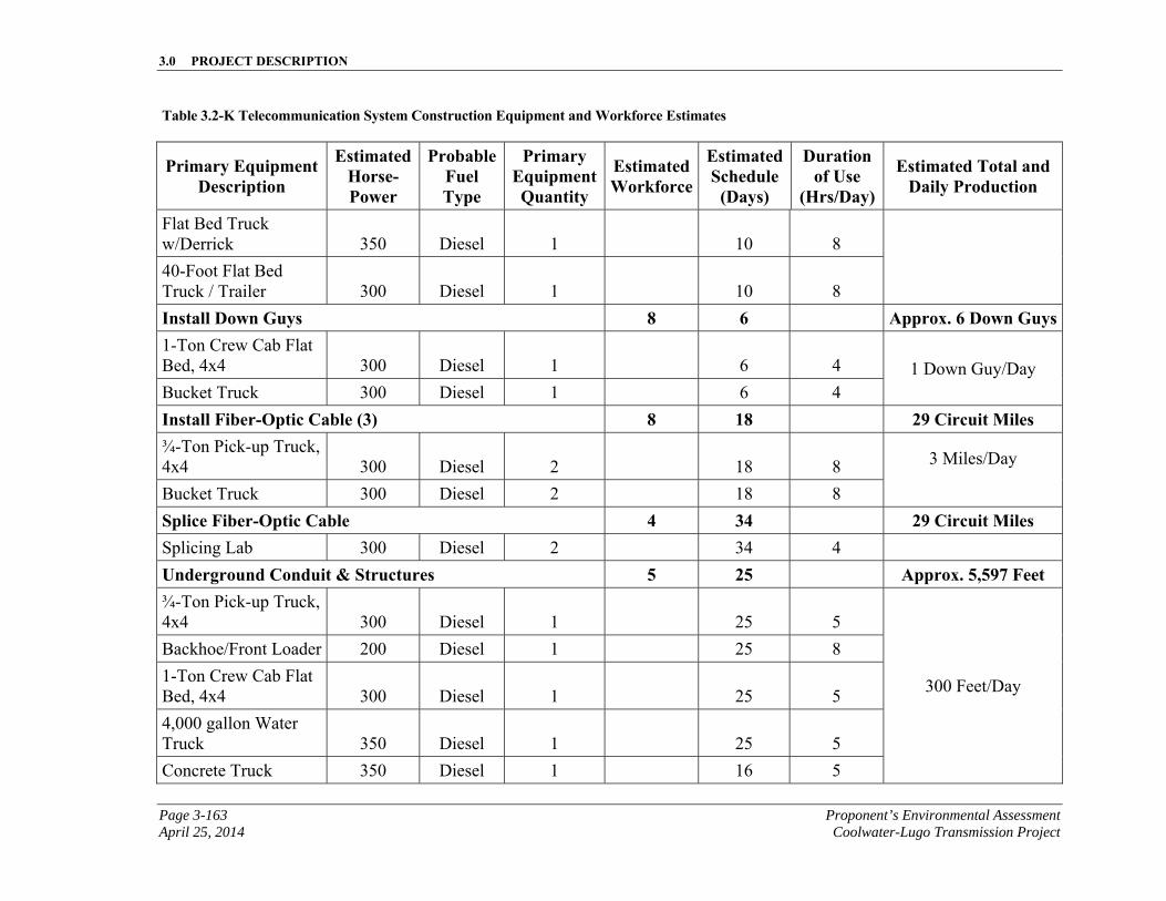
3.0 PROJECT DESCRIPTION
Page 3-163 Proponent’s Environmental Assessment April 25, 2014 Coolwater-Lugo Transmission Project
Table 3.2-K Telecommunication System Construction Equipment and Workforce Estimates
Primary Equipment Description
Estimated Horse-Power
Probable Fuel Type
Primary Equipment Quantity
Estimated Workforce
Estimated Schedule
(Days)
Duration of Use
(Hrs/Day)
Estimated Total and Daily Production
Flat Bed Truck w/Derrick 350 Diesel 1 10 8
40-Foot Flat Bed Truck / Trailer 300 Diesel 1 10 8
Install Down Guys 8 6 Approx. 6 Down Guys1-Ton Crew Cab Flat Bed, 4x4 300 Diesel 1 6 4 1 Down Guy/Day Bucket Truck 300 Diesel 1 6 4
Install Fiber-Optic Cable (3) 8 18 29 Circuit Miles ¾-Ton Pick-up Truck, 4x4 300 Diesel 2 18 8 3 Miles/Day
Bucket Truck 300 Diesel 2 18 8
Splice Fiber-Optic Cable 4 34 29 Circuit Miles Splicing Lab 300 Diesel 2 34 4
Underground Conduit & Structures 5 25 Approx. 5,597 Feet ¾-Ton Pick-up Truck, 4x4 300 Diesel 1 25 5
300 Feet/Day
Backhoe/Front Loader 200 Diesel 1 25 8
1-Ton Crew Cab Flat Bed, 4x4 300 Diesel 1 25 5
4,000 gallon Water Truck 350 Diesel 1 25 5
Concrete Truck 350 Diesel 1 16 5
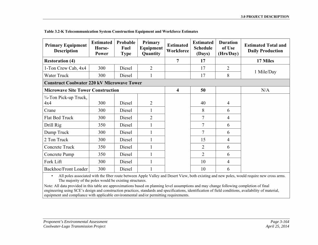
3.0 PROJECT DESCRIPTION
Proponent’s Environmental Assessment Page 3-164 Coolwater-Lugo Transmission Project April 25, 2014
Table 3.2-K Telecommunication System Construction Equipment and Workforce Estimates
Primary Equipment Description
Estimated Horse-Power
Probable Fuel Type
Primary Equipment Quantity
Estimated Workforce
Estimated Schedule
(Days)
Duration of Use
(Hrs/Day)
Estimated Total and Daily Production
Restoration (4) 7 17 17 Miles 1-Ton Crew Cab, 4x4 300 Diesel 2 17 2
1 Mile/Day Water Truck 300 Diesel 1 17 8
Construct Coolwater 220 kV Microwave Tower Microwave Site Tower Construction 4 50 N/A
¾-Ton Pick-up Truck, 4x4 300 Diesel 2
40 4
Crane 300 Diesel 1 8 6
Flat Bed Truck 300 Diesel 2 7 4
Drill Rig 350 Diesel 1 7 6
Dump Truck 300 Diesel 1 7 6
2 Ton Truck 300 Diesel 1 15 4
Concrete Truck 350 Diesel 1 2 6
Concrete Pump 350 Diesel 1 2 6
Fork Lift 300 Diesel 1 10 4
Backhoe/Front Loader 300 Diesel 1 10 6 ▪ All poles associated with the fiber route between Apple Valley and Desert View, both existing and new poles, would require new cross arms.
The majority of the poles would be existing structures. Note: All data provided in this table are approximations based on planning level assumptions and may change following completion of final engineering using SCE’s design and construction practices, standards and specifications, identification of field conditions, availability of material, equipment and compliance with applicable environmental and/or permitting requirements.
3.0 PROJECT DESCRIPTION
Page 3-165 Proponent’s Environmental Assessment April 25, 2014 Coolwater-Lugo Transmission Project
3.2.6.2 Wire Stringing
Wire stringing includes all activities associated with installation of the distribution line conductors onto the distribution poles, including the installation of primary conductor, insulators, and dead-end hardware assemblies. These installations may also include vibration dampeners, weights, spacers and fault indicators. Insulators and stringing sheaves (rollers/ or travelers) may be attached to the conductors as part of the stringing activity, as they are attached to the new structures, during the distribution pole erection process. The dimensions of the area needed for the stringing setups associated with conductor installation would vary depending on structure height and terrain conditions, but would not extend beyond the limits of the approved temporary construction use areas. Vegetation would only be removed where necessary to safely access the site and set up conductor stringing equipment. To the extent possible, stringing setup sites would be located on level ground to minimize the need for grading.
3.2.7 Distribution for Station Light & Power Installation
Approximately 500 feet of a new 12 kV overhead distribution line section would be installed to supply substation light and power to the Proposed Desert View Substation as part of the minmum, initial and full build out options. The new line section would be connected to the existing circuit on the south side of Desert View Road, and extend north, perpendicular to the existing 12 kV distribution circuit towards the south side of the proposed substation perimeter. The circuit would then be transitioned underground, just outside the substation and enter the substation underground.
3.2.7.1 Overhead Distribution Structure Assembly and Installation
Structural components of the distribution equipment would be shipped by truck to the construction material yards and then trucked to the work location. The wood poles and associated equipment would be installed between the south side of Proposed Desert View Substation and the existing circuits on the south side of Desert View Road. Installation of wood poles would be the same as described for Telecommunication in Section 3.2.5.5, Wood Pole Installation. Wood guy stub poles would be installed similarly to wood poles. Ground disturbance would generally be limited to the construction areas. The ground disturbance for each pole installation would typically be approximately 5 square feet per pole and 1 square foot per pole anchor.
The installation of a typical new electrical distribution pole line section would be done before the conductor is energized. Isolation switches where available would be used to de-energize existing circuitry before the newly constructed distribution circuitry is attached to the existing distribution infrastructure. Each new wood pole would be approximately 45-feet to 55-feet high and 7-feet to 14-feet wide. For each new wood pole, a hole approximately 2-feet wide would be excavated, typically using a digger truck or possibly hand-dug if inaccessible by truck. The new pole would then be set in the hole and backfilled with soil which would be tamped for compaction. Appropriate components such as cross arms, insulators and down guys would be installed on the new pole to accommodate the distribution circuit conductor. The new distribution conductors would
3.0 PROJECT DESCRIPTION
Proponent’s Environmental Assessment Page 3-166 Coolwater-Lugo Transmission Project April 25, 2014
then be attached to the new structure. Once the construction is fully completed and cleared for operation, electrical system operations would be performed to energize the newly constructed distribution line section.
3.2.7.2 Wire Stringing
Wire stringing includes all activities associated with installation of the distribution line conductors onto the distribution poles, including the installation of primary conductor, insulators, and dead-end hardware assemblies. These installations may also include vibration dampeners, weights, spacers and fault indicators. Insulators and stringing sheaves (rollers/ or travelers) may be attached to the conductors as part of the stringing activity, as they are attached to the new structures, during the distribution pole erection process. The dimensions of the area needed for the stringing setups associated with conductor installation would vary depending on structure height and terrain conditions, but would not extend beyond the limits of the approved temporary construction use areas. Vegetation would only be removed where necessary to safely access the site and set up conductor stringing equipment. To the extent possible, stringing setup sites would be located on level ground to minimize the need for grading.
3.2.7.3 Underground Distribution Line Installation
Underground structures and conduit would be installed prior to the underground distribution cable. A trench roughly 4 feet deep and 2 feet wide would be dug along all underground distribution power line routes, to facilitate installing conduit for cable from structure to structure, structure to pole and/or structure to the substation wall. Typically four 5-inch conduits would be placed inside the trench from the structure to the next distribution structure, pole or substation wall as required. A layer of slurry would be poured over the conduit for additional protection, and the dug-up soil would be used to backfill the trench.
Typically at the transition of the installation of the overhead to underground distribution facilities, on the last pole (transition/dip pole), the overhead distribution power line would be spliced to a section of distribution power cable. This cable would run in a conduit down the transition pole from overhead into an underground distribution structure located in proximity to the transition/dip pole. The distribution underground cable would then be installed in the conduit and structures. To install the distribution power cable in existing and new underground conduits, a process of pulling the cable through these conduits would be used. The distribution power cables may be terminated as required on distribution underground equipment.
3.2.7.4 Road Access for Distribution Installation
Existing roads within the vicinity of the Proposed Project and roads to be constructed to access the Proposed Transmission Route would be adequate to provide access for installation and ongoing maintenance of the Proposed Distribution Facilities to be construction for station light and power at the Proposed Desert View Substation.
3.0 PROJECT DESCRIPTION
Page 3-167 Proponent’s Environmental Assessment April 25, 2014 Coolwater-Lugo Transmission Project
3.2.7.5 Distribution for Station Light & Power Land Disturbance
Table 3.2-L, Distribution for Station Light & Power Estimated Land Disturbance, provides a summary of the land disturbance estimates associated with the Proposed Distribution Systems for station light and power associated with the Proposed Project.
3.2.7.6 Distribution for Station Light & Power Construction Equipment and Workforce Estimates
The estimated elements, materials and number of personnel and equipment required for construction of the Proposed Distribution for Station Light & Power are summarized in Table 3.2-M, Distribution for Station Light & Power Construction Equipment and Workforce Estimates.
3.3 Post-Construction Activities
SCE would cleanup all areas that would be temporarily disturbed by construction of the Proposed Project (which may include the construction areas and temporary roads, material staging yard, stringing sites, and splicing sites) to as close to pre-construction conditions as feasible, or to the conditions agreed upon between the landowner and SCE following the completion of construction of the Proposed Project.
If restoration occurs within sensitive habitats, a habitat restoration and revegetation plan would be developed by SCE with the appropriate resource agencies and implemented after construction is complete. Additional information pertaining to the habitat restoration and revegetation plan can be found in Section 4.4, Biological Resources.
3.4 Hazardous Materials
Construction of the Proposed Project would require the limited use of hazardous materials, such as fuels, lubricants, and cleaning solvents. All hazardous materials would be stored, handled, and used in accordance with applicable regulations. Material Safety Data Sheets would be made available at the construction site for all crew workers.
SCE would complete a Phase I Environmental Site Assessment (“ESA”) evaluation as a condition of escrow for the Proposed Desert View Substation. Phase I ESAs are conducted in accordance with ASTM International (“ASTM”) Practice E 1527-05 and 40 CFR Part 312 covering AAI. Phase I ESAs include comprehensive and detailed record review, which include site reconnaissance but exclude any intrusive sampling activities.

3.0 PROJECT DESCRIPTION
Proponent’s Environmental Assessment Page 3-168 Coolwater-Lugo Transmission Project April 25, 2014
This page is intentionally blank.
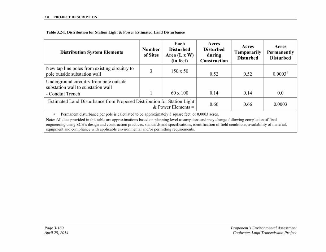
3.0 PROJECT DESCRIPTION
Page 3-169 Proponent’s Environmental Assessment April 25, 2014 Coolwater-Lugo Transmission Project
Table 3.2-L Distribution for Station Light & Power Estimated Land Disturbance
Distribution System Elements Number of Sites
Each Disturbed
Area (L x W) (in feet)
Acres Disturbed
during Construction
Acres Temporarily
Disturbed
Acres Permanently
Disturbed
New tap line poles from existing circuitry to pole outside substation wall
3 150 x 50 0.52 0.52 0.00031
Underground circuitry from pole outside substation wall to substation wall - Conduit Trench
1
60 x 100
0.14
0.14
0.0
Estimated Land Disturbance from Proposed Distribution for Station Light & Power Elements =
0.66 0.66 0.0003
▪ Permanent disturbance per pole is calculated to be approximately 5 square feet, or 0.0003 acres. Note: All data provided in this table are approximations based on planning level assumptions and may change following completion of final engineering using SCE’s design and construction practices, standards and specifications, identification of field conditions, availability of material, equipment and compliance with applicable environmental and/or permitting requirements.
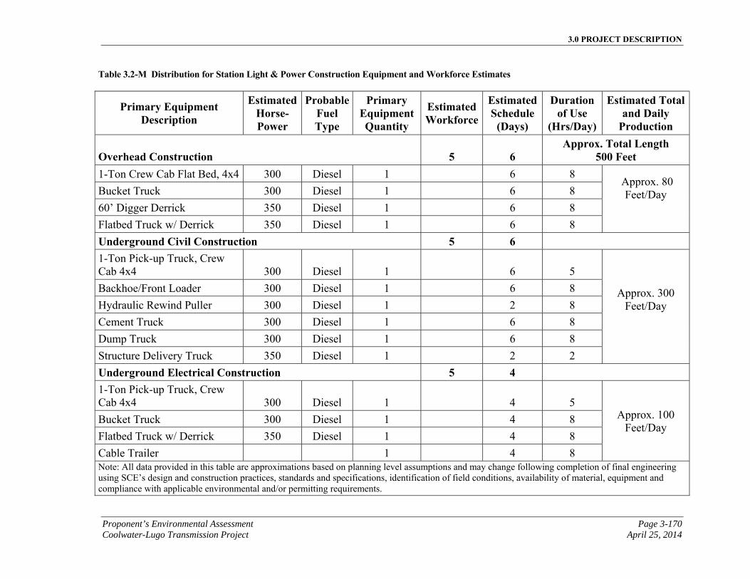
3.0 PROJECT DESCRIPTION
Proponent’s Environmental Assessment Page 3-170 Coolwater-Lugo Transmission Project April 25, 2014
Table 3.2-M Distribution for Station Light & Power Construction Equipment and Workforce Estimates
Primary Equipment Description
Estimated Horse-Power
Probable Fuel Type
Primary Equipment Quantity
Estimated Workforce
Estimated Schedule
(Days)
Duration of Use
(Hrs/Day)
Estimated Total and Daily
Production
Overhead Construction 5 6 Approx. Total Length
500 Feet 1-Ton Crew Cab Flat Bed, 4x4 300 Diesel 1 6 8
Approx. 80 Feet/Day
Bucket Truck 300 Diesel 1 6 8
60’ Digger Derrick 350 Diesel 1 6 8
Flatbed Truck w/ Derrick 350 Diesel 1 6 8
Underground Civil Construction 5 6 1-Ton Pick-up Truck, Crew Cab 4x4 300 Diesel 1 6 5
Approx. 300 Feet/Day
Backhoe/Front Loader 300 Diesel 1 6 8
Hydraulic Rewind Puller 300 Diesel 1 2 8
Cement Truck 300 Diesel 1 6 8
Dump Truck 300 Diesel 1 6 8
Structure Delivery Truck 350 Diesel 1 2 2
Underground Electrical Construction 5 4 1-Ton Pick-up Truck, Crew Cab 4x4 300 Diesel 1 4 5
Approx. 100 Feet/Day
Bucket Truck 300 Diesel 1 4 8
Flatbed Truck w/ Derrick 350 Diesel 1 4 8
Cable Trailer 1 4 8 Note: All data provided in this table are approximations based on planning level assumptions and may change following completion of final engineering using SCE’s design and construction practices, standards and specifications, identification of field conditions, availability of material, equipment and compliance with applicable environmental and/or permitting requirements.
3.0 PROJECT DESCRIPTION
Page 3-171 Proponent’s Environmental Assessment April 25, 2014 Coolwater-Lugo Transmission Project
3.5 Land Use Rights
SCE would acquire property rights to support the Proposed or Alternative Project as required. The Proposed Project transmission lines would be built on a combination of existing and new ROW. This would require acquisition of new land rights and upgrade of existing rights. The ROW land rights SCE would acquire consist primarily of a combination of ROW grants, leases, licenses, fee, and easements over public and private lands. The Desert View Substation land would be purchased in fee. SCE would also acquire temporary construction permits or leases, particularly for pulling sites, helicopter landing areas, temporary facilities, and lay-down areas. SCE would also acquire new access road easements and, as necessary, rights for telecommunication.
3.6 Land Disturbance
Land disturbance would include all areas affected by construction of the Proposed Project. It is estimated that the total permanent land disturbance for the Proposed Project would be 372.4 acres. It is estimated that the Proposed Project would temporarily disturb an additional 1,523.7 acres. The estimated amount of land disturbance for each project component is summarized in Table 3.6-A, Proposed Project Estimated Land Disturbance Summary.
3.6.1 Land Disturbance Summary
Table 3.6-A Proposed Project Estimated Land Disturbance, provides a summary of the land disturbance estimates associated with the Proposed Project.

3.0 PROJECT DESCRIPTION
Proponent’s Environmental Assessment Page 3-172 Coolwater-Lugo Transmission Project April 25, 2014
This page is intentionally blank
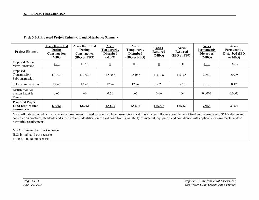
3.0 PROJECT DESCRIPTION
Page 3-173 Proponent’s Environmental Assessment April 25, 2014 Coolwater-Lugo Transmission Project
Table 3.6-A Proposed Project Estimated Land Disturbance Summary
Project Element
Acres Disturbed During
Construction (MBO)
Acres Disturbed During
Construction (IBO or FBO)
Acres Temporarily
Disturbed (MBO)
Acres Temporarily
Disturbed (IBO or FBO)
Acess Restored (MBO)
Acres Restored
(IBO or FBO)
Acres Permanently
Disturbed (MBO)
Acres Permanently
Disturbed (IBO or FBO)
Proposed Desert View Substation
45.3 162.3 0 0.0 0 0.0 45.3 162.3
Proposed Transmission/ Subtransmission
1,720.7 1,720.7 1,510.8 1,510.8 1,510.8 1,510.8 209.9 209.9
Telecommunication 12.43 12.43 12.26 12.26 12.23 12.23 0.17 0.17
Distribution for Station Light & Power
0.66 .66 0.66 .66 0.66 .66 0.0003 0.0003
Proposed Project Land Disturbance Summary =
1,779.1 1,896.1 1,523.7 1,523.7 1,523.7 1,523.7 255.4 372.4
Note: All data provided in this table are approximations based on planning level assumptions and may change following completion of final engineering using SCE’s design and construction practices, standards and specifications, identification of field conditions, availability of material, equipment and compliance with applicable environmental and/or permitting requirements. MBO: minimum build out scenario IBO: initial build out scenario FBO: full build out scenario

3.0 PROJECT DESCRIPTION
Proponent’s Environmental Assessment Page 3-174 Coolwater-Lugo Transmission Project April 25, 2014
This page is intentionally blank
3.0 PROJECT DESCRIPTION
Page 3-175 Proponent’s Environmental Assessment April 25, 2014 Coolwater-Lugo Transmission Project
Project areas would additionally be examined for obvious signs of chemical contamination, such as oil slicks and petroleum odors.
Based on the anticipated volume of hazardous liquid materials, such as mineral oil, in use at the site being in excess of 1,320 gallons, an SPCC Plan would be required (in accordance with 40 C.F.R. Parts112.1-112.7).
3.7 Reusable, Recyclable, and Waste Material Management
Construction of the Proposed Project would result in the generation of various waste materials, including wood, metal, soil, vegetation, and sanitation waste (portable toilets). Sanitation waste (i.e., human generated waste) would be disposed of in accordance with sanitation waste management practices. Material from existing infrastructure that would be removed as part of the Proposed Project such as conductor, steel, concrete, and debris, would be temporarily stored in staging yards as the material awaits salvage, recycling, or disposal.
The existing wood poles removed for the Proposed Project would be returned to staging yards, and either reused by SCE, returned to the manufacturer, disposed of in a Class I hazardous waste landfill, or disposed of in the lined portion of a Regional Water Quality Control Board (“RWQCB”)-certified municipal landfill.
Any material excavated for the Proposed Project could be distributed at each structure site or construction areas, used to backfill excavations, or used for access roads near or within the ROW. Additionally, excess excavated material on BLM land would be used in the ROW or stay onsite until it is sold. The excavated soil may also be made available for use by the landowner, or disposed of off-site at an appropriately licensed waste facility. If contaminated material is encountered during excavation, work would stop at that location and SCE's Spill Response Coordinator would be called to the site to make an assessment and notify the proper authorities, as described in Chapter 4, Section 4.8, Hazards and Hazardous Materials.
3.8 Environmental Surveys
SCE has conducted an initial biological and cultural resources evaluation and would conduct further focused environmental surveys after project approval, but prior to the start of construction. These surveys would identify and/or address any potential sensitive biological and cultural resources that may be impacted by the Proposed Project, including the substation site, transmission route, distribution, and telecommunication line route(s), wire stringing locations, access roads, and staging yards. Where feasible, the information gathered from these surveys may be used to finalize project design in order to avoid sensitive resources, or to minimize the potential impact to sensitive resources from project-related activities. The results of these surveys would also determine the extent to which environmental specialist construction monitors would be required.
Biological resources in the vicinity of the Proposed Project are presented in detail in Section 4.4, Biological Resources.
3.0 PROJECT DESCRIPTION
Proponent’s Environmental Assessment Page 3-176 Coolwater-Lugo Transmission Project April 25, 2014
The following biological surveys would occur prior to construction:
▪ Rare plants
▪ Desert Tortoise Protocol Level Surveys
▪ Arroyo Toad
▪ Mohave Ground Squirrel Habitat Assessment
▪ Wintering Raptors
▪ Rare and Nesting Birds (to include: Cooper’s Hawk, Golden Eagle, Long-eared Owl, Burrowing Owl, Prairie Falcon, Yellow-breasted Chat, Loggerhead Shrike, Bendire’s Thrasher, Le Conte’s Thrasher, Gray Vireo)
Thirty days prior to the start of ground disturbing activity, the following surveys would be conducted:
▪ Clearance Surveys: A clearance survey would be conducted no more than 30 days prior to the start of construction in a particular area to identify potential plant and animal species that may be impacted by construction activities. Clearance surveys include a field survey by a qualified botanist and wildlife biologist and would be limited to areas directly impacted by construction activities.
▪ Active nests: SCE would prepare and implement an adaptive management plan to address nesting birds undertaken in collaboration with the CDFW, USFWS, and BLM. The plan would include the following: nest management and avoidance, field approach (survey methodology, reporting, and monitoring), and the Project avian biologist qualifications. The avian biologist would be responsible for oversight of the avian protection activities including the biological monitors.
Cultural resources in the vicinity of the Proposed Project are presented in detail in Section 4.5, Cultural Resources.
3.9 Worker Environmental Awareness Training
Prior to construction, a Worker Environmental Awareness Program (“WEAP”) would be developed. A presentation would be prepared by SCE and used to train all site personnel prior to the commencement of work. A record of all trained personnel would be kept.
In addition to instruction on compliance with any additional applicant proposed measures and project mitigation measures developed after the pre-construction surveys, all construction personnel would also receive the following:
▪ A list of phone numbers of SCE environmental specialist personnel associated with the Proposed Project (archaeologist, biologist, environmental compliance coordinator, and regional spill response coordinator)
3.0 PROJECT DESCRIPTION
Page 3-177 Proponent’s Environmental Assessment April 25, 2014 Coolwater-Lugo Transmission Project
▪ Instruction on the MDAQMD fugitive dust rules
▪ A review of applicable local, state and federal ordinances, laws and regulations pertaining to historic preservation, a discussion of disciplinary and other actions that could be taken against persons violating historic preservation laws and SCE policies, a review of archaeology, history, prehistory and Native American cultures associated with historical resources in the project vicinity inclusive of instruction on what typical cultural resources look like, and instruction that if discovered during construction, work is to be suspended in the vicinity of any find and the site foreman and archaeologist or environmental compliance coordinator is to be contacted for further direction
▪ Instruction on the importance of maintaining the construction site inclusive of ensuring all food scraps, wrappers, food containers, cans, bottles, and other trash from the Project area would be deposited in closed trash containers (e.g., raven-proof). Trash containers would be removed from the Project as required and would not be permitted to overfill.
▪ Instruction on the individual responsibilities under the Clean Water Act, the project SWPPP, site-specific BMPs, and the location of Material Safety Data Sheets for the project
▪ Instructions to notify the foreman and regional spill response coordinator in case of a hazardous materials spill or leak from equipment, or upon the discovery of soil or groundwater contamination
▪ A copy of the truck routes to be used for material delivery
▪ Instruction that noncompliance with any laws, rules, regulations, or mitigation measures could result in being barred from participating in any remaining construction activities associated with the Proposed Project
▪ Instruction on Ozone Precursor Control Measures
▪ Direction that site vehicles must be properly muffled
3.10 Construction Equipment and Personnel
The estimated elements, materials, and number of personnel and equipment required for construction of the Proposed Project are summarized for each project component in their respective Construction Equipment and Workforce Estimates Table detailed in above sections.
Construction would be performed by either SCE construction crews or contractors. If
SCE construction crews are used they typically would be based at SCE’s local facilities, (e.g., service centers, substation, transmission ROW, etc.) or a temporary material staging yard set up for the project. Contractor construction personnel would be managed by SCE
3.0 PROJECT DESCRIPTION
Proponent’s Environmental Assessment Page 3-178 Coolwater-Lugo Transmission Project April 25, 2014
construction management personnel and based out of the contractor’s existing yard or temporary material staging yard set up for the project. SCE anticipates a total of approximately 600 construction personnel working on any given day. SCE anticipates that crews would work concurrently whenever possible; however, the estimated deployment and number of crew members would vary depending on factors such as material availability, resource availability, and construction scheduling.
In general, construction efforts would occur in accordance with accepted construction industry standards. To the extent possible, SCE would comply with local ordinances for construction activity. Should the need arise to work outside the local ordinances, SCE would request ministerial approvals from San Bernardino County, the Town of Apple Valley, the City of Barstow, and / or the City of Hesperia, as needed. For example, it may be necessary to work during nighttime or outside normal work hours when loads on the lines are reduced.
3.11 Construction Schedule
SCE anticipates that construction of the Proposed Project would take approximately 30 months. Construction would commence following CPUC approval, final engineering, procurement activities, and receipt of all applicable permits. The construction schedule includes the minimum or initial build out of the Proposed Desert View Substation. Full build out of Proposed Desert View Substation would occur in the future as the additional substation components are needed, dictated by load growth, reliability needs, and generation interconnection requests.
3.12 Project Operation and Maintenance
Ongoing operation and maintenance (“O&M”) activities are necessary to ensure reliable service, as well as the safety of the utility worker and the general public, as mandated by the CPUC. SCE facilities are subject to Federal Energy Regulatory Commission jurisdiction. SCE transmission facilities are under operational control of the California Independent System Operator.
The Proposed Desert View Substation would be unstaffed and would function as a remotely controlled substation. The Grid Control Center (“GCC”), Alternate Grid Control Center (“AGCC”) and all Switching Centers are equipped with Energy Management System (“EMS”) workstations allowing them to monitor and respond to alarms as the system status changes. All workstation users have the ability to perform supervisory control of remote station equipment within their jurisdictional area.
Remote substations with Supervisory control are equipped with a Programmable Logic Controller (“PLC”) integrated with Substation Automation System (“SAS”). All automatic functions and data acquisition is performed by the SAS. When a station is supervisory controlled, controllable points can be initiated from the switching center with operational jurisdiction.
3.0 PROJECT DESCRIPTION
Page 3-179 Proponent’s Environmental Assessment April 25, 2014 Coolwater-Lugo Transmission Project
Substation Operators (“SO”) perform station inspections in unmanned substation when there is an indication of trouble. Routine circuit breaker and disconnect switching operations at remotely controlled stations would normally be performed by remote control on orders by the responsible switching center. The System Operators are responsible for maintaining the correct status of all lines and equipment under their jurisdiction.
The transmission, subtransmission, and/or distribution lines would be maintained in a manner consistent with CPUC G.O. 95 and G.O. 128 as applicable, and the National Electrical Safety Code (“NESC”) for those circuits that are located outside of California. Normal operation of the lines would be controlled remotely through SCE control systems, and manually in the field as required. SCE inspects the transmission, subtransmission, and/or distribution lines overhead facilities in a manner consistent with CPUC G.O. 165 a minimum of once per year via ground and/or aerial observation, but usually occurs more frequently based on system reliability. Maintenance would occur as needed and could include activities such as repairing conductors, washing or replacing insulators, repairing or replacing other hardware components, replacing poles and towers, tree trimming, brush and weed control, and access road maintenance. Most regular O&M activities of overhead facilities are performed from existing access roads with no surface disturbance. Repairs done to existing facilities, such as repairing or replacing existing poles and towers, could occur in undisturbed areas. Existing conductors could require re-stringing to repair damages. Some pulling site locations could be in previously undisturbed areas and at times, conductors could be passed through existing vegetation on route to their destination.
Routine access road maintenance is conducted on an annual and/or as-needed basis. Road maintenance includes maintaining a vegetation-free corridor (to facilitate access and for fire prevention) and blading to smooth over washouts, eroded areas, and washboard surfaces as needed. Access road maintenance could include brushing (i.e., trimming or removal of shrubs) approximately two to five feet beyond berms or road’s edge when necessary to keep vegetation from intruding into the roadway. Road maintenance would also include cleaning ditches, moving and establishing berms, clearing and making functional drain inlets to culverts, culvert repair, clearing and establishing water bars, and cleaning and repairing over-side drains. Access road maintenance includes the repair, replacement and installation of storm water diversion devices on an as-needed basis.
Insulators could require periodic washing with water to prevent the buildup of contaminants (dust, salts, droppings, smog, condensation, etc.) and reduce the possibility of electrical arcing which can result in circuit outages and potential fire. Frequency of insulator washing is region specific and based on local conditions and build-up of contaminants. Replacement of insulators, hardware, and other components is performed as needed to maintain circuit reliability.
In the event of pole replacements for operations and maintenance, some towers and/or pole locations and/or laydown areas could be in previously undisturbed areas and could result in ground and/or vegetation disturbance, though attempts would be made to utilize
3.0 PROJECT DESCRIPTION
Proponent’s Environmental Assessment Page 3-180 Coolwater-Lugo Transmission Project April 25, 2014
previously disturbed areas to the greatest extent possible. In some cases new access may need to be created to remove and replace existing towers or poles.
In addition, wood pole testing and treating is a necessary maintenance activity conducted to evaluate the condition of wood structures both above and below ground level. Intrusive inspections require the temporary removal of soil around the base of the pole, usually to a depth of approximately 12 to 18 inches, to check for signs of deterioration. Roads and trails are utilized for access to poles. For impact prevention, all soil removed for intrusive inspections would be reinstalled and compacted at completion of the testing.
Existing conductors could require re-stringing to repair damages. Some pulling site locations could be in previously undisturbed areas and at times, conductors could be passed through existing vegetation on route to their destination.
Regular tree pruning must be performed to be in compliance with existing state and federal laws, rules, and regulations and is crucial for maintaining reliable service, especially during severe weather or disasters. Tree pruning standards for distances from overhead lines have been set by the CPUC (General Order-95, Rule 35), Public Resource Code 4293, California Code of Regulations Title 14, Article 4, and other government and regulatory agencies. SCE’s standard approach to tree pruning is to remove at least the minimum required by law plus one years’ growth (species dependent).
In addition to maintaining vegetation-free access roads, helipads, and clearances around electrical lines, clearance of brush and weeds around poles and/or transmission tower pads, and as required by local jurisdictions on fee owned ROWs, is necessary for fire protection. A 10-foot radial clearance around non-exempt poles (as defined by California Code of Regulations Title 14, Article 4) and a 25 to 50 foot radial clearance around non-exempt towers (as defined by California Code of Regulations Title 14, Article 4) are maintained in accordance with Public Resource Code 4292.
In some cases, towers or poles do not have existing access roads and are accessed on foot, by helicopter, or by creating temporary access areas. O&M related helicopter activities could include transportation of transmission line workers, delivery of equipment and materials to structure sites, structure placement, hardware installation, and conductor (or OPGW) stringing operations. Helicopter landing areas could occur where access by road is infeasible. In addition, helicopters must be able to land within SCE ROWs, which could include landing on access or spur roads. A 35-foot clearance of small trees/shrubs around the touch-down pad may be required and maintained as well as a 70 feet wide “approach/takeoff” slot to the touch-down pad at a 12 degree angle.
In addition to regular O&M activities, SCE conducts a wide variety of emergency repairs in response to emergency situations such as damage resulting from high winds, storms, fires, and other natural disasters, and accidents. Such repairs could include replacement of downed poles, transmission towers, lines or re-stringing conductors. Emergency repairs could be needed at any time. SCE would notify the CPUC and/or BLM as soon as feasible of any emergency repairs. The notice would include a description of the work, location of the transmission facilities, and cause of the emergency, if known. The CPUC
3.0 PROJECT DESCRIPTION
Page 3-181 Proponent’s Environmental Assessment April 25, 2014 Coolwater-Lugo Transmission Project
and/or BLM and SCE would work together to agree upon habitat restoration needs after the emergency.
The telecommunication equipment would be subject to maintenance and repair activities on an as needed or emergency basis. Activities would include replacing defective circuit boards, damaged radio antennas or feedlines and testing the equipment. Telecommunication equipment would also be subject to routine inspection and preventative maintenance such as filter change-outs or software and hardware upgrades. Most regular O&M activities of telecommunication equipment are performed at Substation or Communication Sites and inside the equipment rooms and are accessed from existing access roads with no surface disturbance; helicopter transportation may be required to access remote Communications Sites for routine or emergency maintenance activities. Access road maintenance is performed as mentioned in the Project Operations Transmission and Subtransmission section above.
The telecommunication cables would be maintained on an as needed or emergency basis. Maintenance activities would include patrolling, testing, repairing and replacing damaged cable and hardware. Most regular maintenance activities of overhead facilities are performed from existing access roads with no surface disturbance. Repairs done to existing facilities, such as repairing or replacing existing cables and re-stringing cables, could occur in undisturbed areas. Access and habitat restoration, as mentioned in the Project Operations Transmission and Subtransmission section above may be required for routine or emergency maintenance activities.
3.13 Decommissioning
Prior to removal or abandonment of the facilities that would be permitted to be constructed on BLM lands, California State Lands Commission lands, and private lands or within a reasonable time following termination of the BLM ROW grant, in accordance with the appropriate regulations, SCE would prepare a removal and restoration plan. The removal and restoration plan would address removal of SCE’s facilities from the permitted area, and any requirements for habitat restoration and revegetation (refer to Biological Resources Section 4.4 of this PEA). The removal and restoration plan would then be approved by the permitting agency before implementation.
3.0 PROJECT DESCRIPTION
Proponent’s Environmental Assessment Page 3-182 Coolwater-Lugo Transmission Project April 25, 2014
3.14 Project Alternatives
The Alternative Project includes the following elements:
▪ Construction of a new alternative 500/220/115/12 kV substation (“Alternative Desert View Substation”), west of Lucerne Valley and southeast of the Town of Apple Valley. The Alternative Substation would be an unstaffed, automated substation, initially functioning as a switching station, with a potential capacity of 4,000 MVA at full build out. Under the minimum build out scenario, 13.5 acres would be graded and associated equipment surrounded by a chain link fence would be installed. Under the initial build out scenario, 86 acres would be graded and a four position 220 kV switchrack and associated equipment surrounded by a wall would be installed;
▪ Installation of an Alternative 220 kV Transmission Line approximately 38.0 miles long, and of double-circuit construction in new ROW located between the existing Coolwater Switchyard and the location of the future Jasper Substation, southwest of the intersection of Haynes Road and SR-2471. Under the minimum build out scenario option, one side of the double-circuit structures are strung whereas under initial and full build out senarios, both sides of the double-circuit structures are strung;
▪ Installation of an Alternative 220 kV Transmission Line approximately 14.9 miles long, and of double-circuit construction in existing SCE transmission ROW, located between the location southwest of the intersection of Haynes Road and SR-247 and the Alternative Desert View Substation;
▪ Installation of an Alternative 500 kV Transmission Line, initially energized at 220 kV, approximately 20.4 miles long, and of single-circuit construction in new ROW, from the Alternative Desert View Substation to the existing Lugo Substation;
▪ Removal of approximately 29.1 miles of the existing Lugo-Pisgah No.1 220 kV transmission line between existing Lugo Substation and a location southwest of the intersection of Haynes Road and SR-247;
▪ Relocation of existing subtransmission lines, distribution, and telecommunication facilities, as needed, to accommodate construction of the Alternative Project, meet CPUC G.O. 95 clearance standards, and facilitate safer construction and operation of the existing, as well as new electrical utility infrastructure;
▪ Installation of distribution facilities from the south side of Desert View Road to the Alternative Desert View Substation site to provide station light and power;
1 The future Jasper Substation would be triggered by a generation interconnection project and would be processed under a separate Permit to Construct.
3.0 PROJECT DESCRIPTION
Page 3-183 Proponent’s Environmental Assessment April 25, 2014 Coolwater-Lugo Transmission Project
▪ Installation of Alternative Telecommunication Facilities to connect the Alternative Project to SCE’s existing telecommunication system to include OPGW on the Alternative Transmission Line Route; a new microwave tower, antenna dish and equipment at Coolwater Switchyard; and, installation of ADSS fiber-optic cable between Apple Valley Substation and the Alternative Desert View Substation Site on a combination of existing structures and new wood poles, and between Gale Substation and Pisgah Substation on existing structures; and,
▪ Other major components associated with the Alternative Project include modifications and new equipment installation at existing SCE substations, and removal and relocation of underground utilities.
The alternative project description is based on planning level assumptions. Exact details would be determined following completion of final engineering, identification of field conditions, availability of labor, material, and equipment, and compliance with applicable environmental and permitting requirements.
3.14.1 Alternative Substation Description
Components of the Alternative Desert View Substation that differ from the Proposed Desert View Substation are presented in this section. The Alternative Desert View Substation is paired with the Alternative Transmission Route for purposes of this analysis.
The Alternative Desert View Substation would be a new 500/220/115/12 kV unstaffed, automated substation.
Under the initial and final build out scenarios, tThe enclosed area of the substation would encompass approximately 82.0 acres located in unincorporated San Bernardino County, to the southeast of the Town of Apple Valley and west of Lucerne Valley. The dimensions of the substation would be approximately 2,090 feet by 1,700 feet.
Under the minimum build out scenario, the Alternative Desert View Substation would encompass the same acreage as the Proposed Desert View Substation under minimum build out scenario.
The alternative substation site is vacant desert land containing a single-family residential home in the southeast corner of the site, which would be demolished prior to construction activities. In addition there are storage containers on the northwest corner of the substation site and in the center of the site, which would need to be removed. Potential utilities available in the area may include electrical, gas, water, and telecommunications. Existing 12 kV power lines are located along the adjacent street ROWs.
SCE considers the California Building Code and the IEEE 693, Recommended Practices for Seismic Design of substations when designing substation structures and equipment.
The substation components for the Alternative Substation would be the same as described for the Proposed Substation. Variables that would be unique to the Alternative
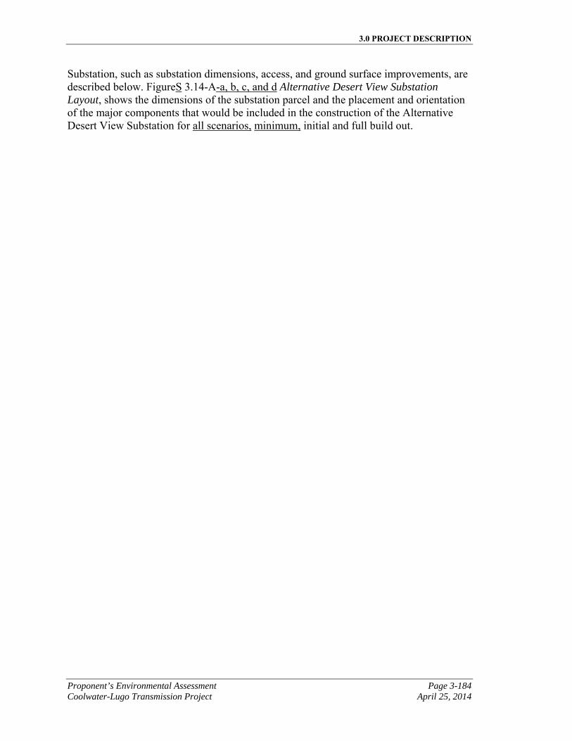
3.0 PROJECT DESCRIPTION
Proponent’s Environmental Assessment Page 3-184 Coolwater-Lugo Transmission Project April 25, 2014
Substation, such as substation dimensions, access, and ground surface improvements, are described below. FigureS 3.14-A-a, b, c, and d Alternative Desert View Substation Layout, shows the dimensions of the substation parcel and the placement and orientation of the major components that would be included in the construction of the Alternative Desert View Substation for all scenarios, minimum, initial and full build out.
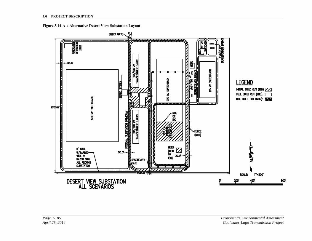
3.0 PROJECT DESCRIPTION
Page 3-185 Proponent’s Environmental Assessment April 25, 2014 Coolwater-Lugo Transmission Project
Figure 3.14-A-a Alternative Desert View Substation Layout
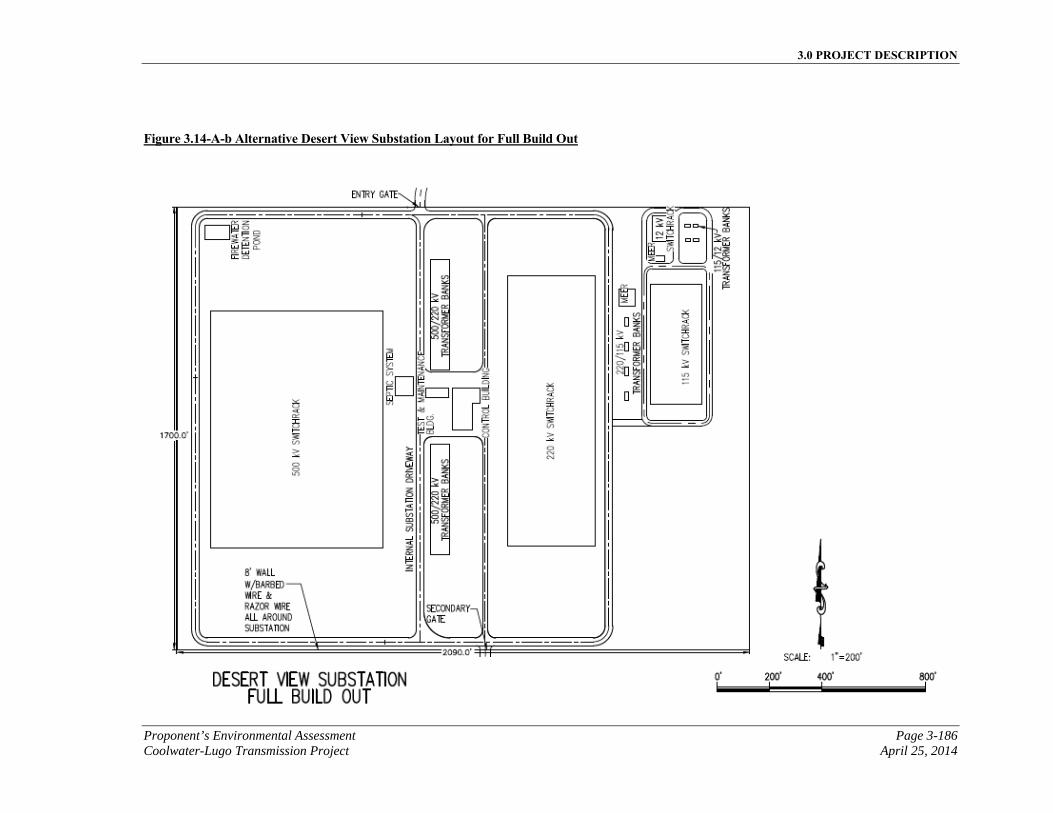
3.0 PROJECT DESCRIPTION
Proponent’s Environmental Assessment Page 3-186 Coolwater-Lugo Transmission Project April 25, 2014
Figure 3.14-A-b Alternative Desert View Substation Layout for Full Build Out
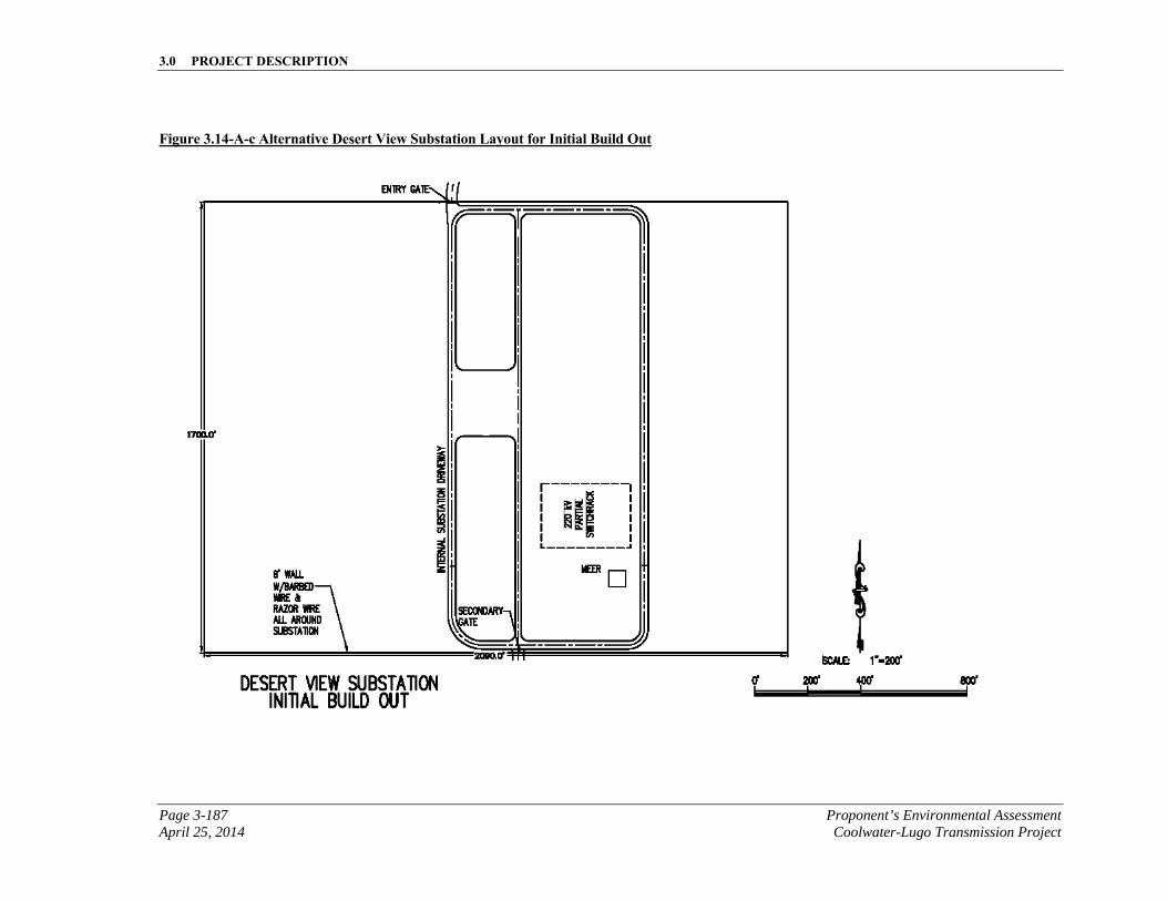
3.0 PROJECT DESCRIPTION
Page 3-187 Proponent’s Environmental Assessment April 25, 2014 Coolwater-Lugo Transmission Project
Figure 3.14-A-c Alternative Desert View Substation Layout for Initial Build Out
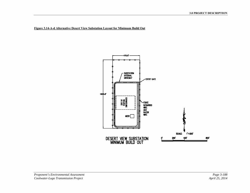
3.0 PROJECT DESCRIPTION
Proponent’s Environmental Assessment Page 3-188 Coolwater-Lugo Transmission Project April 25, 2014
Figure 3.14-A-d Alternative Desert View Substation Layout for Minimum Build Out
3.0 PROJECT DESCRIPTION
Page 3-189 Proponent’s Environmental Assessment April 25, 2014 Coolwater-Lugo Transmission Project
3.14.1.1 Substation Access
Minimum Build Out
At minimum build out, access to the Alternative Desert View Substation would be provided via the existing Wren Street, accessed via the existing Milpas Drive. SCE would pave an asphalt concrete access road on Wren Street up to approximately 24 feet in width and approximately 1.61 miles (or 8,500 feet) in length, with 2-foot shoulders, to the substation driveway. The asphalt concrete-paved driveway would extend from the edge of the access road ROW to the substation gate. The driveway would be approximately 40 feet in width and 2,100 feet would be constructed. Secondary access would be provided via the substation’s south entrance located on Desert View Road, which would have an aggregate base surface.
Initial Build Out
At initial build out, access to the Alternative Desert View Substation would be provided via the existing Wren Street, accessed via the existing Milpas Drive. SCE would pave an asphalt concrete access road on Wren Street up to approximately 24 feet in width and approximately 1.61 miles (or 8,500 feet) in length, with 2-foot shoulders, to the substation driveway. The asphalt concrete-paved driveway would extend from the edge of the access road ROW to the substation gate. The driveway would be approximately 40 feet in width and 1,090 feet would be constructed. Secondary access would be provided via the substation’s south entrance located on Desert View Road, which would have an aggregate base surface.
Full Build Out
At full build out, the secondary access from the substation’s south entrance would be asphalt concrete-paved. No additional road improvements would be needed for substation access at full build out, assuming the initial build out has been completed.
3.14.1.2 Ground Surface Improvements
The approximate surface area and volumes for the below-grade components of the alternative Desert View Substation are shown in Table 3.14-A, Alternative Substation Cut and Fill Grading Summary.
Ground surface of the alternative substation site would be finished with materials imported to the site and excavated on the site. The approximate surface area and volumes of these materials are listed below in Table 3.14-B, Alternative Substation Ground Surface Improvement Materials.

3.0 PROJECT DESCRIPTION
Proponent’s Environmental Assessment Page 3-190 Coolwater-Lugo Transmission Project April 25, 2014
This page is intentionally blank
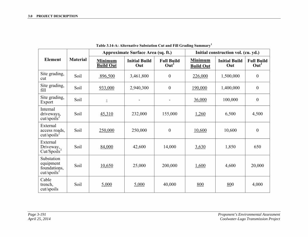
3.0 PROJECT DESCRIPTION
Page 3-191 Proponent’s Environmental Assessment April 25, 2014 Coolwater-Lugo Transmission Project
Table 3.14-A: Alternative Substation Cut and Fill Grading Summary1
Element Material Approximate Surface Area (sq. ft.) Initial construction vol. (cu. yd.)
Minimum Build Out
Initial Build Out
Full Build Out1
Minimum Build Out
Initial Build Out
Full Build Out1
Site grading, cut Soil 896,500 3,461,800 0 226,000 1,500,000 0
Site grading, fill Soil 933,000 2,940,300 0 190,000 1,400,000 0
Site grading, Export Soil - - - 36,000 100,000 0
Internal driveways, cut/spoils2
Soil 45,310 232,000 155,000 1,260 6,500 4,500
External access roads, cut/spoils2
Soil 250,000 250,000 0 10,600 10,600 0
External Driveway, Cut/Spoils3
Soil 84,000 42,600 14,000 3,630 1,850 650
Substation equipment foundations, cut/spoils2
Soil 10,650 25,000 200,000 1,600 4,600 20,000
Cable trench, cut/spoils
Soil 5,000 5,000 40,000 800 800 4,000
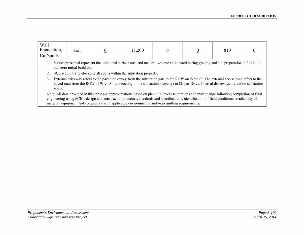
3.0 PROJECT DESCRIPTION
Proponent’s Environmental Assessment Page 3-192 Coolwater-Lugo Transmission Project April 25, 2014
Wall Foundation, Cut/spoils
Soil 0 15,200 0 0 810 0
1. Values presented represent the additional surface area and material volume anticipated during grading and site preparation at full build out from initial build out.
2. SCE would try to stockpile all spoils within the substation property.
3. External driveway refers to the paved driveway from the substation gate to the ROW on Wren St. The external access road refers to the paved road from the ROW of Wren St. (connecting to the substation property) to Milpas Drive. Internal driveways are within substation walls.
Note: All data provided in this table are approximations based on planning level assumptions and may change following completion of final engineering using SCE’s design and construction practices, standards and specifications, identification of field conditions, availability of material, equipment and compliance with applicable environmental and/or permitting requirements.
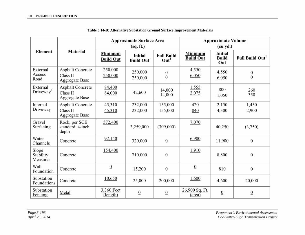
3.0 PROJECT DESCRIPTION
Page 3-193 Proponent’s Environmental Assessment April 25, 2014 Coolwater-Lugo Transmission Project
Table 3.14-B: Alternative Substation Ground Surface Improvement Materials
Element Material
Approximate Surface Area (sq. ft.)
Approximate Volume (cu yd.)
Minimum Build Out
Initial Build Out
Full Build Out1
Minimum Build Out
Initial Build Out
Full Build Out1
External Access Road
Asphalt Concrete Class II Aggregate Base
250,000 250,000
250,000 250,000
0 0
4,550 6,050
4,550 6,050
0 0
External Driveway2
Asphalt Concrete Class II Aggregate Base
84,400 84,000 42,600 14,000
14,000
1,555 2,075
800 1,050
260 350
Internal Driveway
Asphalt Concrete Class II Aggregate Base
45,310 45,310
232,000 232,000
155,000 155,000
420 840
2,150 4,300
1,450 2,900
Gravel Surfacing
Rock, per SCE standard, 4-inch depth
572,400 3,259,000 (309,000)
7,070 40,250 (3,750)
Water Channels Concrete 92,140 320,000 0 6,900 11,900 0
Slope Stability Measures
Concrete 154,400
710,000 0 1,910
8,800 0
Wall Foundation Concrete 0 15,200 0 0 810 0
Substation Foundations Concrete 10,650 25,000 200,000 1,600 4,600 20,000
Substation Fencing Metal 3,360 Feet
(length) 0 0 26,900 Sq. Ft. (area) 0 0
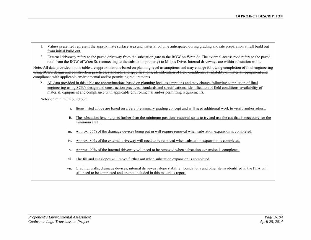
3.0 PROJECT DESCRIPTION
Proponent’s Environmental Assessment Page 3-194 Coolwater-Lugo Transmission Project April 25, 2014
1. Values presented represent the approximate surface area and material volume anticipated during grading and site preparation at full build out from initial build out.
2. External driveway refers to the paved driveway from the substation gate to the ROW on Wren St. The external access road refers to the paved road from the ROW of Wren St. (connecting to the substation property) to Milpas Drive. Internal driveways are within substation walls.
Note: All data provided in this table are approximations based on planning level assumptions and may change following completion of final engineering using SCE’s design and construction practices, standards and specifications, identification of field conditions, availability of material, equipment and compliance with applicable environmental and/or permitting requirements.
3. All data provided in this table are approximations based on planning level assumptions and may change following completion of final engineering using SCE’s design and construction practices, standards and specifications, identification of field conditions, availability of material, equipment and compliance with applicable environmental and/or permitting requirements.
Notes on minimum build out:
i. Items listed above are based on a very preliminary grading concept and will need additional work to verify and/or adjust.
ii. The substation fencing goes further than the minimum positions required so as to try and use the cut that is necessary for the minimum area.
iii. Approx. 75% of the drainage devices being put in will require removal when substation expansion is completed.
iv. Approx. 80% of the external driveway will need to be removed when substation expansion is completed.
v. Approx. 90% of the internal driveway will need to be removed when substation expansion is completed.
vi. The fill and cut slopes will move further out when substation expansion is completed.
vii. Grading, walls, drainage devices, internal driveway, slope stability, foundations and other items identified in the PEA will still need to be completed and are not included in this materials report.
3.0 PROJECT DESCRIPTION
Page 3-195 Proponent’s Environmental Assessment April 25, 2014 Coolwater-Lugo Transmission Project
Ground surface of the alternative substation site would be finished with materials imported to the site and excavated on the site. The approximate surface area and volumes of these materials are listed below in Table 3.14-B, Alternative Substation Ground Surface Improvement Materials.
3.14.2 Alternative 500 kV and 220 kV Transmission Line Description
The Alternative Transmission Line Route consists of one segment of single-circuit and double-circuit 500 kV construction (Segment 6), initially energized at 220 kV, and eight segments of double-circuit, 220 kV construction (Segments 12, 11, 9/10, 8, 2, 4, 5, and 5B). Segments 12, 2 and 5 are common with the Proposed Transmission Line Route and are described in Section 3.1.3, 500 kV and 220 kV Transmission Line Description.
The Alternative 500 kV Transmission Route (Segment 6) would connect to the Alternative Desert View Substation and existing Lugo Substation. New LSTs and TSPs would be installed to accommodate the new transmission line segment, within new ROW.
The Alternative 220 kV Transmission Route consists of nine segments (Segments 12, 11, 9 or 10, 8, 2, 4, 5, and 5B). New LSTs and TSPs would be installed to accommodate the new transmission line segments, within a combination of new and existing ROW. Construction would also include removal of existing towers located in the ROW southwest of the intersection of Haynes Road and SR-247, and alternative Desert View Substation.
The following paragraph describes the Alternative 500 kV Transmission Route segment for the Alternative Project:
Alternative 500 kV Transmission Route (Segment 6) would originate at the western side of the Alternative Desert View Substation and would extend generally south to the existing SCE 500 kV transmission corridor (Eldorado-Lugo and Lugo-Mohave 500 kV lines). Segment 6 would then parallel the existing transmission lines westerly on the north side of the corridor to the existing Lugo Substation. Segment 6 would also include one smaller sub-segment, into the southwest side of the Alternative Desert View Substation from the existing Lugo-Pisgah No. 1 and No. 2 line ROW, approximately 0.6 mile, which would be removed after build out of the 500 kV portion of Desert View Substation.1 Segment 6 including the subsegment, would be approximately 20.4 miles in length, within new ROW.
1 The sub-segment and the associated structures would be removed once the 500 kV portion of Desert View Substation is built out. For purposes of analyzing the worst case environmental impact of the Alternative Project, it is included as part of Segment 6 of the Alternative Transmission Line Route.
3.0 PROJECT DESCRIPTION
Proponent’s Environmental Assessment Page 3-196 Coolwater-Lugo Transmission Project April 25, 2014
The following paragraphs describe the Alternative 220 kV Transmission Route segments for the Alternative Project:
For minimum build out, one side of the double circuit 220 kV structures would be strung in Segments 12, 11, 9 or 10, 8, 2, and 4. Additionally, for Segments 5 and 5B both sides of the double circuit 220 kV structures would be strung.
For initial and full build out, both sides of the double circuit 220 kV structures would be strung in Segments 12, 11, 9 or 10, 8, 2, 4, 5 and 5B).
Alternative Transmission Line Segment 12 220 kV (1.4 miles) would be the same as the Proposed Transmission Line Segment 12, described in Section 3.1.3, 500 kV and 220 kV Transmission Line Description.
Alternative Transmission Line Segment 11 would originate at a point just south of I-40 and proceed west until it reaches a point south of the intersection of I-40 and Daggett-Yermo Road. Segment 11 would be approximately 1.8 miles in length.
Alternative Transmission Line Segment 9 would originate at a point south of the intersection of I-40 and Daggett-Yermo Road and would extend generally west parallel to an existing SCE 115 kV line, and would then turn north and parallel the eastern boundary of the Marine Corps Logistics Base Barstow for approximately 0.5 mile where it would then continue west through the Base property. Segment 9 would then turn southwest for 0.5 mile until crossing SR-247. Segment 9 would then turn south along the west side of SR-247 to a point just west of SR-247 near the Barstow Sanitary Landfill. Segment 9 would be approximately 8.7 miles in length, within new ROW.
Segment 10 was developed as an alternative to Segment 9 as an option that would avoid crossing Marine Corps Logistics Base Barstow property. Either Segment 9 or Segment 10 could be used as part of the Alternative 220 kV Transmission Route but not both. Alternative Transmission Line Segment 10 would originate at a point south of the intersection of I-40 and Daggett-Yermo Road and would extend generally southwest for approximately 1.3 miles. Segment 10 would then turn west for 6.4 miles following the southern boundary of the Marine Corps Logistics Base Barstow to a point just west of SR-247 near the Barstow Sanitary Landfill. Segment 10 would be approximately 7.7 miles in length, within new ROW.
Alternative Transmission Line Segment 8 would originate at a point just west of SR-247 near the Barstow Sanitary Landfill and would extend generally southwest across open land until reaching Stoddard Wells Road, and would then follow Stoddard Wells Road to the LADWP transmission corridor. SCE is proposing to cross under the LADWP transmission corridor at this location, just west of Stoddard Wells Road1. Segment 8 would be approximately 10.1 miles in length, within new ROW.
1 The specific crossing location under the LADWP corridor is subject to final engineering and the outcome of consultation with LADWP.
3.0 PROJECT DESCRIPTION
Page 3-197 Proponent’s Environmental Assessment April 25, 2014 Coolwater-Lugo Transmission Project
Alternative Transmission Line Segment 2 220 kV (11.7 miles) would be the same as the Proposed Transmission Line Segment 2, described in Section 3.1.3, 500 kV and 220 kV Transmission Line Description.
Alternative Transmission Line Segment 4 would originate at the intersection of Lucerne Valley Cutoff Road and SR-247 and would extend generally south following the base of the Granite Mountain foothills and terminate just northwest of the intersection of SR-247 and Haynes Roads (approximate location of future Jasper Substation). Segment 4 would be approximately 4.4 miles in length, within new ROW.
Alternative Transmission Line Segment 5 220 kV (12.9 miles) would be the same as the Proposed Transmission Line Segment 5, described in Section 3.1.3, 500 kV and 220 kV Transmission Line Description.
Alternative Transmission Line Segment 5B would originate just west of the intersection of Desert View Road and Milpas Drive in existing SCE ROW, and would extend southwest within the existing ROW to a point just west of the intersection of Laguna Seca Drive and Powerline Road. From this point, Segment 5B would proceed generally northwest to terminate in the east side of the Alternative Desert View Substation. Segment 5B would be approximately 2.0 miles in length. The portion of Segment 5B located in existing SCE ROW would replace a portion of the existing Lugo-Pisgah No. 1 220 kV transmission line proposed for removal. The portion of Segment 5B from the existing ROW northwest to the east side of Alternative Desert View Substation would be in new ROW.
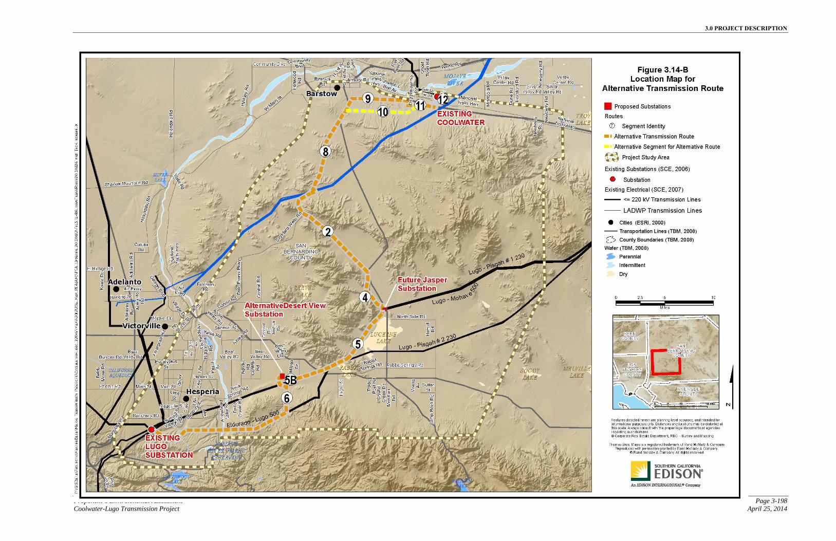
3.0 PROJECT DESCRIPTION
Proponent’s Environmental Assessment Page 3-198 Coolwater-Lugo Transmission Project April 25, 2014
Figure 3.14-A Location Map for Alternative Transmission Route
3.0 PROJECT DESCRIPTION
Page 3-199 Proponent’s Environmental Assessment April 25, 2014 Coolwater-Lugo Transmission Project
This page is intentionally blank.
3.0 PROJECT DESCRIPTION
Proponent’s Environmental Assessment Page 3-200 Coolwater-Lugo Transmission Project April 25, 2014
3.14.3 Alternative 115 kV Subtransmission Description
At minimum or initial build out of Alternative Desert View Substation, there are no 115 kV subtransmission line routes to be constructed.
At full build out, the Alternative Substation could accommodate a maximum of eight 115 kV subtransmission circuits, as described for the Proposed Project. These circuits would be constructed from the Alternative Substation to areas of demand on an as-needed basis and with consideration of the following guidelines:
▪ The location of the current load growth;
▪ Existing electrical subtransmission facilities in the area; and
▪ The location of roads and existing SCE ROWs.
These 115 kV subtransmission circuits cannot be designed at this time due to the uncertainty of where load relief will be needed and where future load growth will precisely occur, in addition to unforeseen changes in the physical and environmental condition of the surrounding area. Accordingly, the location and routing of each of these potential 115 kV subtransmission circuits would be determined in accordance with CPUC G.O. 131-D in the future.
3.14.3.1 Subtransmission Getaways
As part of the minimum or initial build out, no subtransmission getaways would be constructed at the Alternative Desert View Substation.
The full build out of the Alternative Desert View Substation could include up to eight subtransmission getaways. The getaways for the full build out of the Alternative Desert View Substation would be the same as described for the Proposed Project in Section 3.1.4.1, Subtransmission Getaways.
3.14.3.2 Subtransmission Line Relocations
The relocation or modifications of existing 115 kV subtransmission lines could be required for the construction of the Alternative Project. The 115 kV relocations or modifications would require the same structure types, insulators, conductors, raptor protection, and undergrounding work as described for the Proposed Transmission Line Route. Please refer back to Section 3.1.5, Subtransmission Line Relocations, for additional detail.
3.14.3.3 Alternative Project Subtransmission Line Crossings Description
SCE has identified potential crossings, relocations, and/or idling of existing 115 kV subtransmission facilities on Segment 11, 9 and 8 of the Alternative Transmission Line Route. The potential work associated with these locations is described below by route
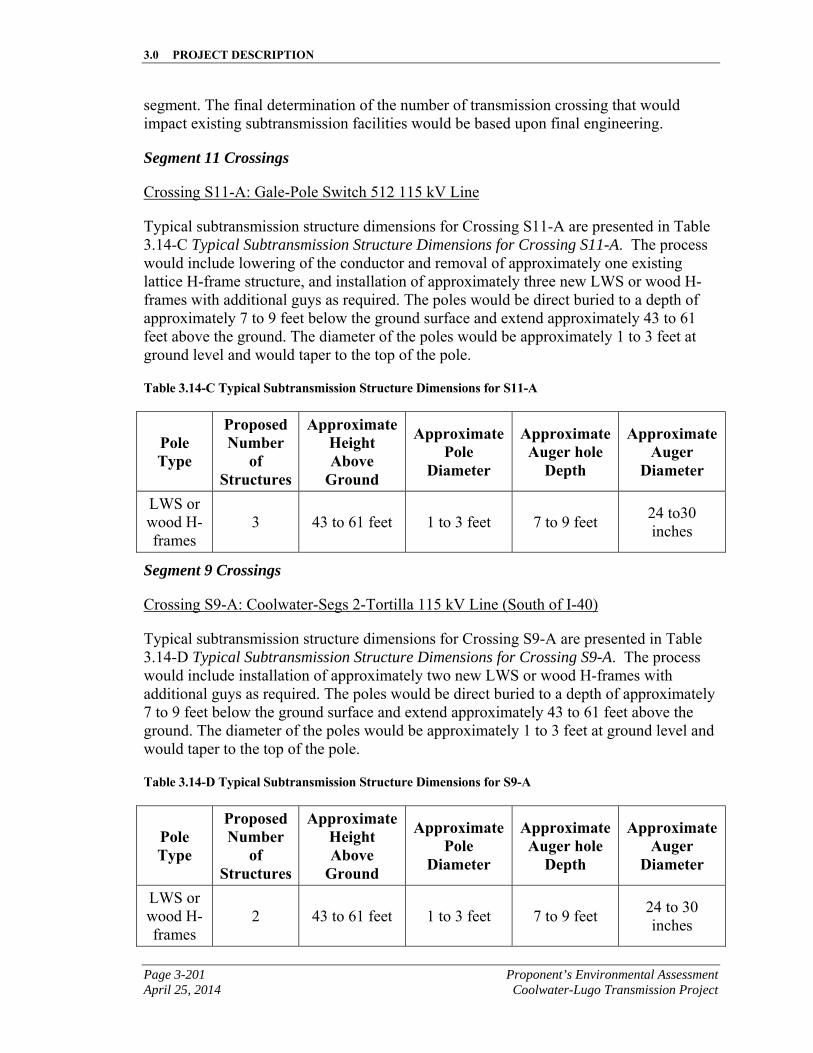
3.0 PROJECT DESCRIPTION
Page 3-201 Proponent’s Environmental Assessment April 25, 2014 Coolwater-Lugo Transmission Project
segment. The final determination of the number of transmission crossing that would impact existing subtransmission facilities would be based upon final engineering.
Segment 11 Crossings
Crossing S11-A: Gale-Pole Switch 512 115 kV Line
Typical subtransmission structure dimensions for Crossing S11-A are presented in Table 3.14-C Typical Subtransmission Structure Dimensions for Crossing S11-A. The process would include lowering of the conductor and removal of approximately one existing lattice H-frame structure, and installation of approximately three new LWS or wood H-frames with additional guys as required. The poles would be direct buried to a depth of approximately 7 to 9 feet below the ground surface and extend approximately 43 to 61 feet above the ground. The diameter of the poles would be approximately 1 to 3 feet at ground level and would taper to the top of the pole.
Table 3.14-C Typical Subtransmission Structure Dimensions for S11-A
Pole Type
Proposed Number
of Structures
Approximate Height Above
Ground
Approximate Pole
Diameter
Approximate Auger hole
Depth
Approximate Auger
Diameter
LWS or wood H-frames
3 43 to 61 feet 1 to 3 feet 7 to 9 feet 24 to30 inches
Segment 9 Crossings
Crossing S9-A: Coolwater-Segs 2-Tortilla 115 kV Line (South of I-40)
Typical subtransmission structure dimensions for Crossing S9-A are presented in Table 3.14-D Typical Subtransmission Structure Dimensions for Crossing S9-A. The process would include installation of approximately two new LWS or wood H-frames with additional guys as required. The poles would be direct buried to a depth of approximately 7 to 9 feet below the ground surface and extend approximately 43 to 61 feet above the ground. The diameter of the poles would be approximately 1 to 3 feet at ground level and would taper to the top of the pole.
Table 3.14-D Typical Subtransmission Structure Dimensions for S9-A
Pole Type
Proposed Number
of Structures
Approximate Height Above
Ground
Approximate Pole
Diameter
Approximate Auger hole
Depth
Approximate Auger
Diameter
LWS or wood H-frames
2 43 to 61 feet 1 to 3 feet 7 to 9 feet 24 to 30 inches
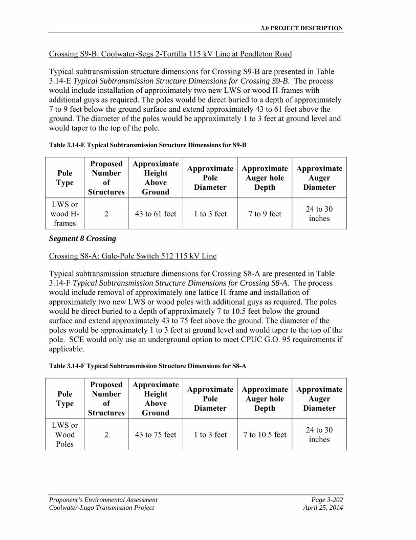
3.0 PROJECT DESCRIPTION
Proponent’s Environmental Assessment Page 3-202 Coolwater-Lugo Transmission Project April 25, 2014
Crossing S9-B: Coolwater-Segs 2-Tortilla 115 kV Line at Pendleton Road
Typical subtransmission structure dimensions for Crossing S9-B are presented in Table 3.14-E Typical Subtransmission Structure Dimensions for Crossing S9-B. The process would include installation of approximately two new LWS or wood H-frames with additional guys as required. The poles would be direct buried to a depth of approximately 7 to 9 feet below the ground surface and extend approximately 43 to 61 feet above the ground. The diameter of the poles would be approximately 1 to 3 feet at ground level and would taper to the top of the pole.
Table 3.14-E Typical Subtransmission Structure Dimensions for S9-B
Pole Type
Proposed Number
of Structures
Approximate Height Above
Ground
Approximate Pole
Diameter
Approximate Auger hole
Depth
Approximate Auger
Diameter
LWS or wood H-frames
2 43 to 61 feet 1 to 3 feet 7 to 9 feet 24 to 30 inches
Segment 8 Crossing
Crossing S8-A: Gale-Pole Switch 512 115 kV Line
Typical subtransmission structure dimensions for Crossing S8-A are presented in Table 3.14-F Typical Subtransmission Structure Dimensions for Crossing S8-A. The process would include removal of approximately one lattice H-frame and installation of approximately two new LWS or wood poles with additional guys as required. The poles would be direct buried to a depth of approximately 7 to 10.5 feet below the ground surface and extend approximately 43 to 75 feet above the ground. The diameter of the poles would be approximately 1 to 3 feet at ground level and would taper to the top of the pole. SCE would only use an underground option to meet CPUC G.O. 95 requirements if applicable.
Table 3.14-F Typical Subtransmission Structure Dimensions for S8-A
Pole Type
Proposed Number
of Structures
Approximate Height Above
Ground
Approximate Pole
Diameter
Approximate Auger hole
Depth
Approximate Auger
Diameter
LWS or Wood Poles
2 43 to 75 feet 1 to 3 feet 7 to 10.5 feet 24 to 30 inches
3.0 PROJECT DESCRIPTION
Page 3-203 Proponent’s Environmental Assessment April 25, 2014 Coolwater-Lugo Transmission Project
Underground Subtransmission Line Installation
The underground subtransmission line installation for the crossings described above would be similar to as described for the Proposed Project in Section 3.1.5.3, Proposed Project Subtransmission Line Crossings Description. In addition, for the Alternative Project SCE would potentially remove two lattice H-frame structures. The underground installation could require boring underneath a water resource with bore pits on each side of the resource.
3.14.4 Alternative Telecommunication Description
Telecommunication infrastructure would be added to connect the Alternative Project to SCE’s telecommunication system and would provide SCADA, protective relaying, data transmission, and telephone services for the Alternative Project and associated facilities.
For the Alternative Project, the new telecommunication infrastructure be the same as described for the Proposed Project, with the exception of the portion of the Apple Valley to Desert View fiber route from Del Oro Road to the Alternative Desert View Substation Site and the OPGW route which would follow the Alternative Transmission Route instead of the Proposed Transmission Route.
At minimum or initial build out, the Alternative Desert View Substation would include a MEER as described in Section 3.1.1.11, Mechanical and Electrical Equipment Room, which would house project-related telecommunication equipment.
At full build out, the Proposed Desert View Substation would include a Control Building as described in Section 3.1.1.9, Control and Test & Maintenance Buildings. The 220 kV MEER control and monitoring equipment for the substation would be remotely controlled or relocated to the Control Building.
The Alternative OPGW Telecommunication Route would follow the same path as the Alternative Transmission Line Route, as presented on Figure 3.15-C, Alternative Telecommunication Route.
Where the Alternative Transmission Line Route would cross underneath existing transmission lines, underground fiber-optic cable would be installed for operational reliability. The Alternative Transmission Line Route would cross underneath other transmission lines at three locations, two of which would be the same as described for the Proposed OPGW Telecommunication Route in Section 3.1.6, Telecommunication Description. The Alternative OPGW Telecommunication Route would not cross under the four LADWP transmission lines at a location southwest of Coolwater Switchyard as it would for the Proposed Transmission Route. It would instead cross under the LADWP corridor farther west and south, at the intersection of the LADWP corridor and Stoddard Wells Roads (the intersection of transmission line route Segment 8 and Segment 2).
In addition, the ADSS Fiber-Optic Cable from Apple Valley Substation to the Alternative Desert View Substation would be the same up to the intersection of Japatul Road and Del
3.0 PROJECT DESCRIPTION
Proponent’s Environmental Assessment Page 3-204 Coolwater-Lugo Transmission Project April 25, 2014
Oro Road, at which point the Alternative Telecommunication Route would turn south on Japatul Road on approximately 21 new overhead poles, to the north side of Desert View Road. At Desert View Road, the route would extend east on approximately 11 new poles. At Alternative Desert View Substation, SCE would install a riser on the last pole and drop down into new conduit. The route would continue north approximately 500 feet in new underground conduit to the Alternative Desert View Substation MEER building.
Telecommunication work at existing SCE facilities for the Alternative Project, including but not limited to, Lugo Substation, Coolwater Switchyard, Apple Valley Substation, Gale Substation, Pisgah Substation, and the Ord Mountain Communications Site would be the same as described for the Proposed Project in Section 3.1.2, Modifications to Existing Substations Description. The underground construction for the Alternative Telecommunication System would be the same as described for the Proposed Project in Section 3.2.6.4, Underground Fiber-Optic Cable Installation.
3.14.5 Alternative Distribution
The distribution components and the installation and wire stringing associated with the Alternative Desert View Substation would be the same as described for the proposed substation in Section 3.1.7, Distribution, with the exception of the location of the distribution route for station light and power, and the path for the distribution getaways exiting the alternative substation at full build out, as described below.
For the minimum or initial build out of Alternative Desert View Substation, a new 12 kV overhead distribution line section would be installed to supply substation light and power to the Alternative Substation. The new line section would be connected to the existing circuit on the south side of Desert View Road, and would extend north, perpendicular to the existing 12 kV distribution circuit towards the south side of the Alternative Substation perimeter. The circuit would then be transitioned underground, just outside the substation and enter the substation underground.
For the full build out of Alternative Desert View Substation, duct banks extending north out of the substation would travel to the first distribution structure, typically an underground distribution vault, located outside of the Alternative Desert View Substation wall, along the substation’s northern perimeter. The duct banks extending south would travel south for a few feet and then turn east within the alternative substation, ultimately extending to a distribution structure located outside the substation on Bellview Avenue, which borders the alternative substation’s eastern perimeter.
3.14.6 Alternative Project Construction Plan
The following section describes the construction activities associated with installing the components of Alternative Project. The information presented focuses on those construction activities that would be different from what was described in Section 3.2, Proposed Project Construction Plan, for the Proposed Project.
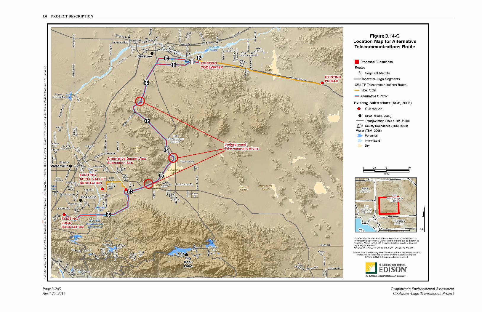
3.0 PROJECT DESCRIPTION
Page 3-205 Proponent’s Environmental Assessment April 25, 2014 Coolwater-Lugo Transmission Project
Figure 3.14-B Location Map for Alternative Telecommunications Route

3.0 PROJECT DESCRIPTION
Proponent’s Environmental Assessment Page 3-206 Coolwater-Lugo Transmission Project April 25, 2014
This page is intentionally blank.
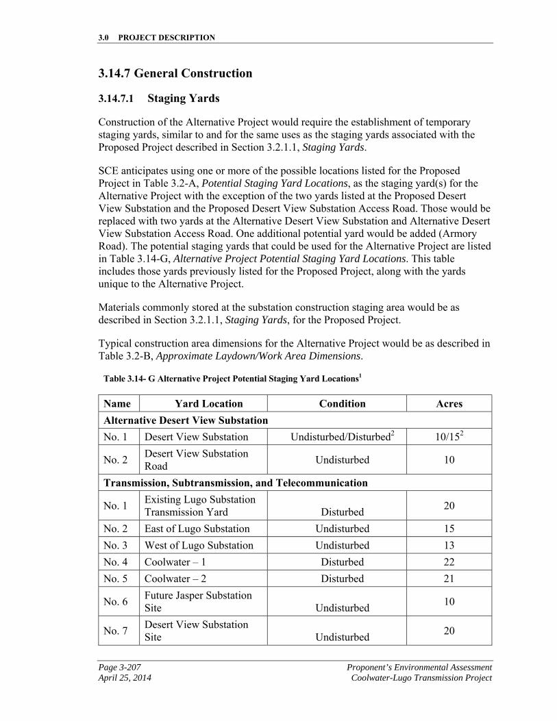
3.0 PROJECT DESCRIPTION
Page 3-207 Proponent’s Environmental Assessment April 25, 2014 Coolwater-Lugo Transmission Project
3.14.7 General Construction
3.14.7.1 Staging Yards
Construction of the Alternative Project would require the establishment of temporary staging yards, similar to and for the same uses as the staging yards associated with the Proposed Project described in Section 3.2.1.1, Staging Yards.
SCE anticipates using one or more of the possible locations listed for the Proposed Project in Table 3.2-A, Potential Staging Yard Locations, as the staging yard(s) for the Alternative Project with the exception of the two yards listed at the Proposed Desert View Substation and the Proposed Desert View Substation Access Road. Those would be replaced with two yards at the Alternative Desert View Substation and Alternative Desert View Substation Access Road. One additional potential yard would be added (Armory Road). The potential staging yards that could be used for the Alternative Project are listed in Table 3.14-G, Alternative Project Potential Staging Yard Locations. This table includes those yards previously listed for the Proposed Project, along with the yards unique to the Alternative Project.
Materials commonly stored at the substation construction staging area would be as described in Section 3.2.1.1, Staging Yards, for the Proposed Project.
Typical construction area dimensions for the Alternative Project would be as described in Table 3.2-B, Approximate Laydown/Work Area Dimensions.
Table 3.14- G Alternative Project Potential Staging Yard Locations1
Name Yard Location Condition Acres Alternative Desert View Substation No. 1 Desert View Substation Undisturbed/Disturbed2 10/152
No. 2 Desert View Substation Road
Undisturbed 10
Transmission, Subtransmission, and Telecommunication
No. 1 Existing Lugo Substation Transmission Yard Disturbed
20
No. 2 East of Lugo Substation Undisturbed 15
No. 3 West of Lugo Substation Undisturbed 13
No. 4 Coolwater – 1 Disturbed 22
No. 5 Coolwater – 2 Disturbed 21
No. 6 Future Jasper Substation Site Undisturbed
10
No. 7 Desert View Substation Site Undisturbed
20
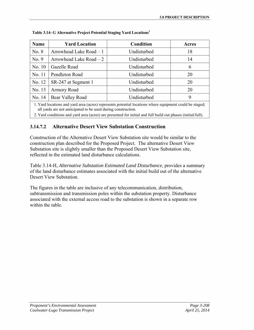
3.0 PROJECT DESCRIPTION
Proponent’s Environmental Assessment Page 3-208 Coolwater-Lugo Transmission Project April 25, 2014
Table 3.14- G Alternative Project Potential Staging Yard Locations1
Name Yard Location Condition Acres No. 8 Arrowhead Lake Road – 1 Undisturbed 18
No. 9 Arrowhead Lake Road – 2 Undisturbed 14
No. 10 Gazelle Road Undisturbed 6
No. 11 Pendleton Road Undisturbed 20
No. 12 SR-247 at Segment 1 Undisturbed 20
No. 13 Armory Road Undisturbed 20
No. 14 Bear Valley Road Undisturbed 9 1. Yard locations and yard area (acres) represents potential locations where equipment could be staged;
all yards are not anticipated to be used during construction. 2. Yard conditions and yard area (acres) are presented for initial and full build out phases (initial/full).
3.14.7.2 Alternative Desert View Substation Construction
Construction of the Alternative Desert View Substation site would be similar to the construction plan described for the Proposed Project. The alternative Desert View Substation site is slightly smaller than the Proposed Desert View Substation site, reflected in the estimated land disturbance calculations.
Table 3.14-H, Alternative Substation Estimated Land Disturbance, provides a summary of the land disturbance estimates associated with the initial build out of the alternative Desert View Substation.
The figures in the table are inclusive of any telecommunication, distribution, subtransmission and transmission poles within the substation property. Disturbance associated with the external access road to the substation is shown in a separate row within the table.
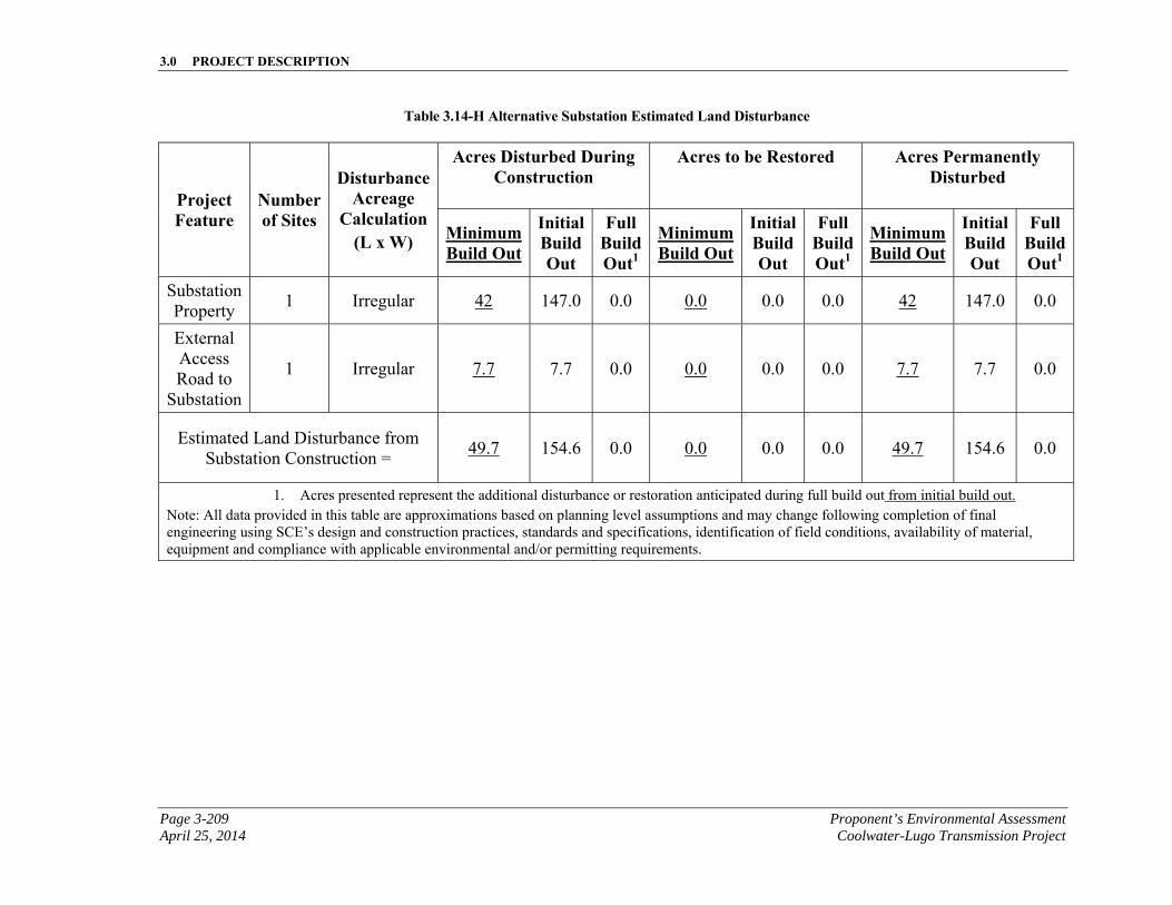
3.0 PROJECT DESCRIPTION
Page 3-209 Proponent’s Environmental Assessment April 25, 2014 Coolwater-Lugo Transmission Project
Table 3.14-H Alternative Substation Estimated Land Disturbance
Project Feature
Number of Sites
Disturbance Acreage
Calculation (L x W)
Acres Disturbed During Construction
Acres to be Restored Acres Permanently Disturbed
Minimum Build Out
Initial Build Out
Full Build Out1
Minimum Build Out
Initial Build Out
Full Build Out1
Minimum Build Out
Initial Build Out
Full Build Out1
Substation Property
1 Irregular 42 147.0 0.0 0.0 0.0 0.0 42 147.0 0.0
External Access Road to
Substation
1 Irregular 7.7 7.7 0.0 0.0 0.0 0.0 7.7 7.7 0.0
Estimated Land Disturbance from Substation Construction =
49.7 154.6 0.0 0.0 0.0 0.0 49.7 154.6 0.0
1. Acres presented represent the additional disturbance or restoration anticipated during full build out from initial build out. Note: All data provided in this table are approximations based on planning level assumptions and may change following completion of final engineering using SCE’s design and construction practices, standards and specifications, identification of field conditions, availability of material, equipment and compliance with applicable environmental and/or permitting requirements.
3.0 PROJECT DESCRIPTION
Proponent’s Environmental Assessment Page 3-210 Coolwater-Lugo Transmission Project April 25, 2014
This page is intentionally blank.
3.0 PROJECT DESCRIPTION
Page 3-211 Proponent’s Environmental Assessment April 25, 2014 Coolwater-Lugo Transmission Project
3.14.7.3 Alternative Substation Construction Equipment and Workforce Estimates
The estimated elements, materials and number of personnel and equipment required for construction of the Alternative Desert View Substation at minimum and initial build out are summarized in Table 3.14-I, Alternative Substation Construction Equipment and Workforce Estimates (Minimum and Initial Build Out).
Construction would be performed by either SCE crews or contractors. Contractor construction personnel would be managed by SCE construction management personnel. SCE anticipates a total of approximately 15 to 75 construction personnel working on any given day. SCE anticipates that crews would work concurrently whenever possible; however, the estimated deployment and number of crew members would be dependent upon local jurisdiction permitting, material availability, and construction scheduling.
In general, construction efforts would occur in accordance with accepted construction industry standards.
The estimated elements, materials and number of personnel and equipment required for construction of the Alternative Desert View Substation at full build out are summarized in Table 3.14-J, Alternative Substation Construction Equipment and Workforce Estimates (Full Build Out).
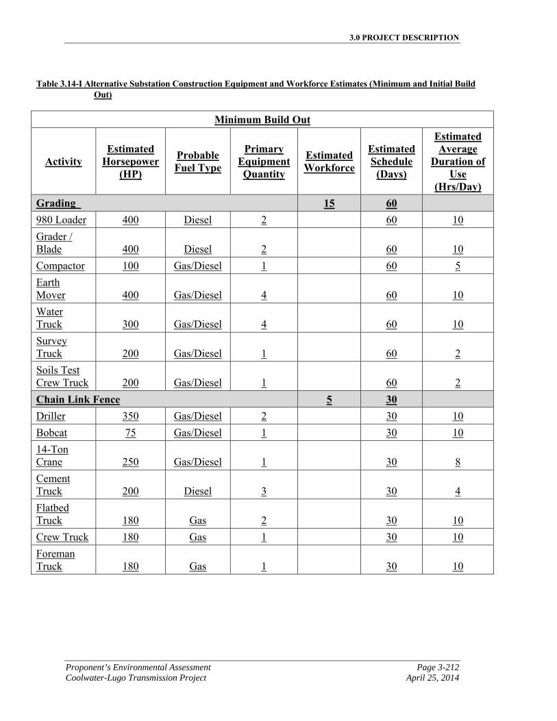
3.0 PROJECT DESCRIPTION
Proponent’s Environmental Assessment Page 3-212 Coolwater-Lugo Transmission Project April 25, 2014
Table 3.14-I Alternative Substation Construction Equipment and Workforce Estimates (Minimum and Initial Build
Out)
Minimum Build Out
Activity Estimated
Horsepower (HP)
Probable Fuel Type
Primary Equipment Quantity
Estimated Workforce
Estimated Schedule
(Days)
Estimated Average
Duration of Use
(Hrs/Day) Grading 15 60 980 Loader 400 Diesel 2 60 10
Grader / Blade 400 Diesel 2
60 10
Compactor 100 Gas/Diesel 1 60 5
Earth Mover 400 Gas/Diesel 4
60 10
Water Truck 300 Gas/Diesel 4
60 10
Survey Truck 200 Gas/Diesel 1
60 2
Soils Test Crew Truck 200 Gas/Diesel 1
60 2
Chain Link Fence 5 30 Driller 350 Gas/Diesel 2 30 10
Bobcat 75 Gas/Diesel 1 30 10
14-Ton Crane 250 Gas/Diesel 1
30 8
Cement Truck 200 Diesel 3
30 4
Flatbed Truck 180 Gas 2
30 10
Crew Truck 180 Gas 1 30 10
Foreman Truck 180 Gas 1
30 10
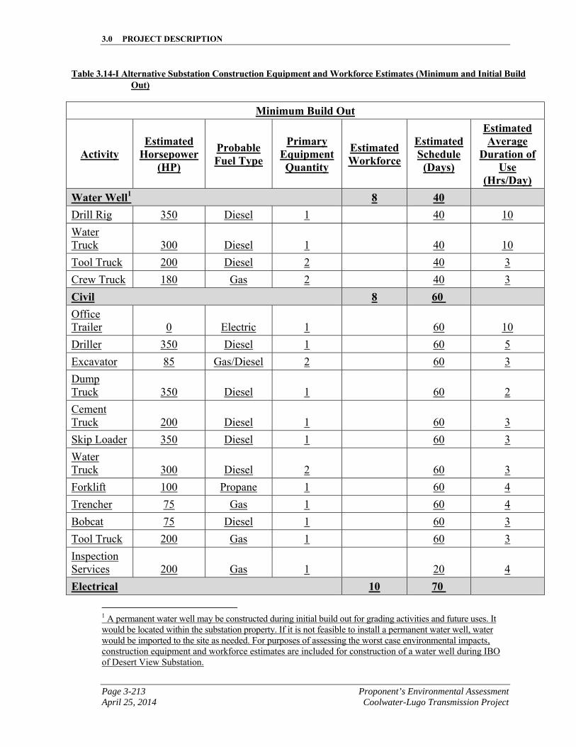
3.0 PROJECT DESCRIPTION
Page 3-213 Proponent’s Environmental Assessment April 25, 2014 Coolwater-Lugo Transmission Project
Table 3.14-I Alternative Substation Construction Equipment and Workforce Estimates (Minimum and Initial Build Out)
Minimum Build Out
Activity Estimated
Horsepower (HP)
Probable Fuel Type
Primary Equipment Quantity
Estimated Workforce
Estimated Schedule
(Days)
Estimated Average
Duration of Use
(Hrs/Day) Water Well1 8 40
Drill Rig 350 Diesel 1 40 10
Water Truck 300 Diesel 1
40 10
Tool Truck 200 Diesel 2 40 3
Crew Truck 180 Gas 2 40 3
Civil 8 60 Office Trailer 0 Electric 1
60 10
Driller 350 Diesel 1 60 5
Excavator 85 Gas/Diesel 2 60 3
Dump Truck 350 Diesel 1
60 2
Cement Truck 200 Diesel 1
60 3
Skip Loader 350 Diesel 1 60 3
Water Truck 300 Diesel 2
60 3
Forklift 100 Propane 1 60 4
Trencher 75 Gas 1 60 4
Bobcat 75 Diesel 1 60 3
Tool Truck 200 Gas 1 60 3
Inspection Services 200 Gas 1
20 4
Electrical 10 70
1 A permanent water well may be constructed during initial build out for grading activities and future uses. It would be located within the substation property. If it is not feasible to install a permanent water well, water would be imported to the site as needed. For purposes of assessing the worst case environmental impacts, construction equipment and workforce estimates are included for construction of a water well during IBO of Desert View Substation.
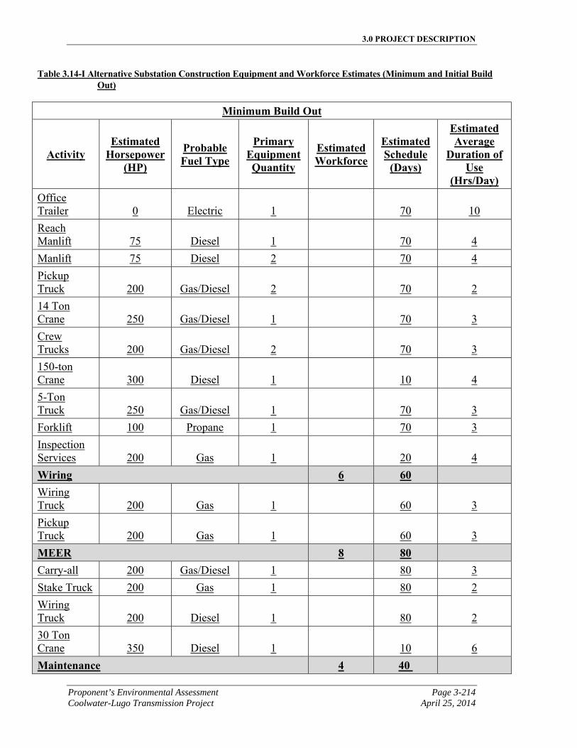
3.0 PROJECT DESCRIPTION
Proponent’s Environmental Assessment Page 3-214 Coolwater-Lugo Transmission Project April 25, 2014
Table 3.14-I Alternative Substation Construction Equipment and Workforce Estimates (Minimum and Initial Build Out)
Minimum Build Out
Activity Estimated
Horsepower (HP)
Probable Fuel Type
Primary Equipment Quantity
Estimated Workforce
Estimated Schedule
(Days)
Estimated Average
Duration of Use
(Hrs/Day) Office Trailer 0 Electric 1
70 10
Reach Manlift 75 Diesel 1
70 4
Manlift 75 Diesel 2 70 4
Pickup Truck 200 Gas/Diesel 2
70 2
14 Ton Crane 250 Gas/Diesel 1
70 3
Crew Trucks 200 Gas/Diesel 2
70 3
150-ton Crane 300 Diesel 1
10 4
5-Ton Truck 250 Gas/Diesel 1
70 3
Forklift 100 Propane 1 70 3
Inspection Services 200 Gas 1
20 4
Wiring 6 60 Wiring Truck 200 Gas 1
60 3
Pickup Truck 200 Gas 1
60 3
MEER 8 80 Carry-all 200 Gas/Diesel 1 80 3
Stake Truck 200 Gas 1 80 2
Wiring Truck 200 Diesel 1
80 2
30 Ton Crane 350 Diesel 1
10 6
Maintenance 4 40
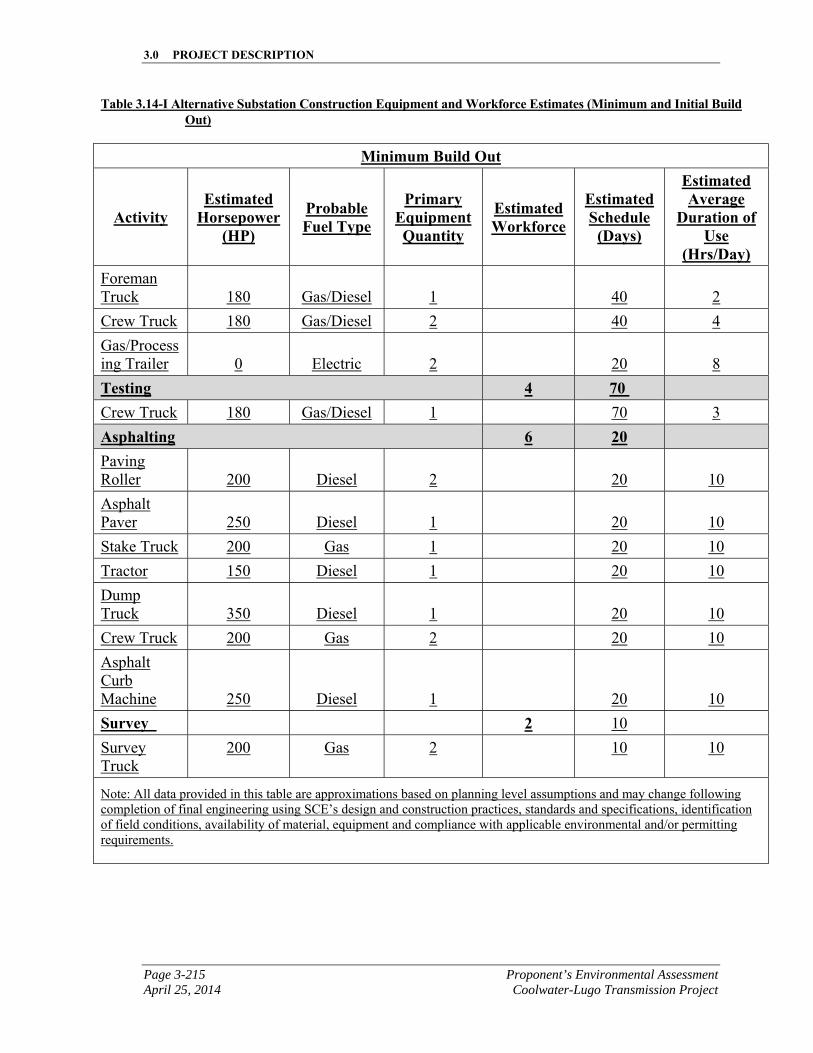
3.0 PROJECT DESCRIPTION
Page 3-215 Proponent’s Environmental Assessment April 25, 2014 Coolwater-Lugo Transmission Project
Table 3.14-I Alternative Substation Construction Equipment and Workforce Estimates (Minimum and Initial Build Out)
Minimum Build Out
Activity Estimated
Horsepower (HP)
Probable Fuel Type
Primary Equipment Quantity
Estimated Workforce
Estimated Schedule
(Days)
Estimated Average
Duration of Use
(Hrs/Day) Foreman Truck 180 Gas/Diesel 1
40 2
Crew Truck 180 Gas/Diesel 2 40 4
Gas/Processing Trailer 0 Electric 2
20 8
Testing 4 70 Crew Truck 180 Gas/Diesel 1 70 3
Asphalting 6 20 Paving Roller 200 Diesel 2
20 10
Asphalt Paver 250 Diesel 1
20 10
Stake Truck 200 Gas 1 20 10
Tractor 150 Diesel 1 20 10
Dump Truck 350 Diesel 1
20 10
Crew Truck 200 Gas 2 20 10
Asphalt Curb Machine 250 Diesel 1
20 10
Survey 2 10
Survey Truck
200 Gas 2 10 10
Note: All data provided in this table are approximations based on planning level assumptions and may change following completion of final engineering using SCE’s design and construction practices, standards and specifications, identification of field conditions, availability of material, equipment and compliance with applicable environmental and/or permitting requirements.
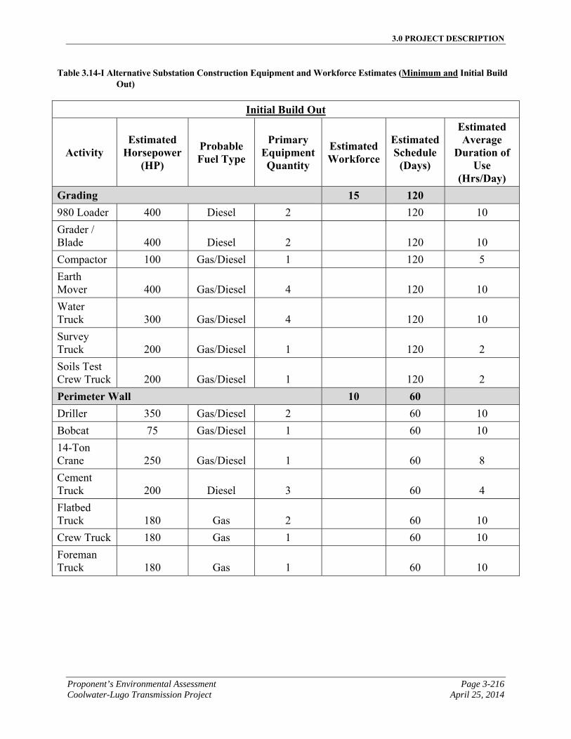
3.0 PROJECT DESCRIPTION
Proponent’s Environmental Assessment Page 3-216 Coolwater-Lugo Transmission Project April 25, 2014
Table 3.14-I Alternative Substation Construction Equipment and Workforce Estimates (Minimum and Initial Build Out)
Initial Build Out
Activity Estimated
Horsepower (HP)
Probable Fuel Type
Primary Equipment Quantity
Estimated Workforce
Estimated Schedule
(Days)
Estimated Average
Duration of Use
(Hrs/Day) Grading 15 120 980 Loader 400 Diesel 2 120 10
Grader / Blade 400 Diesel 2
120 10
Compactor 100 Gas/Diesel 1 120 5
Earth Mover 400 Gas/Diesel 4
120 10
Water Truck 300 Gas/Diesel 4
120 10
Survey Truck 200 Gas/Diesel 1
120 2
Soils Test Crew Truck 200 Gas/Diesel 1
120 2
Perimeter Wall 10 60 Driller 350 Gas/Diesel 2 60 10
Bobcat 75 Gas/Diesel 1 60 10
14-Ton Crane 250 Gas/Diesel 1
60 8
Cement Truck 200 Diesel 3
60 4
Flatbed Truck 180 Gas 2
60 10
Crew Truck 180 Gas 1 60 10
Foreman Truck 180 Gas 1
60 10
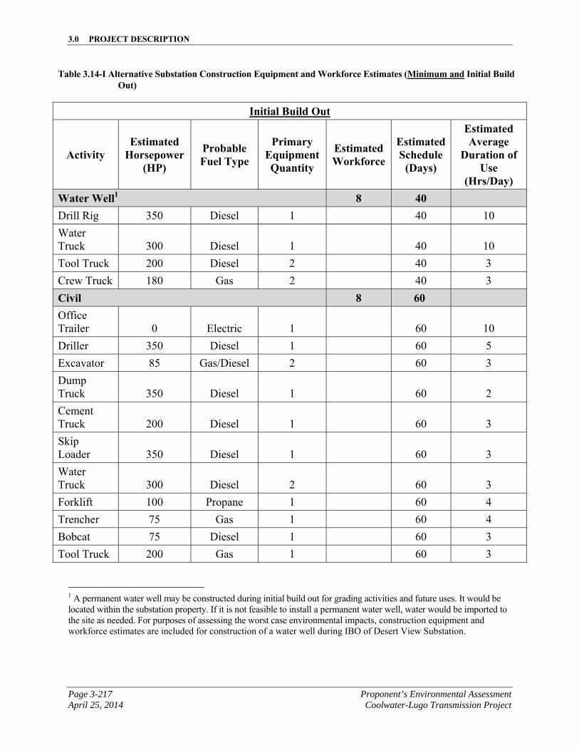
3.0 PROJECT DESCRIPTION
Page 3-217 Proponent’s Environmental Assessment April 25, 2014 Coolwater-Lugo Transmission Project
Table 3.14-I Alternative Substation Construction Equipment and Workforce Estimates (Minimum and Initial Build Out)
Initial Build Out
Activity Estimated
Horsepower (HP)
Probable Fuel Type
Primary Equipment Quantity
Estimated Workforce
Estimated Schedule
(Days)
Estimated Average
Duration of Use
(Hrs/Day) Water Well1 8 40
Drill Rig 350 Diesel 1 40 10
Water Truck 300 Diesel 1
40 10
Tool Truck 200 Diesel 2 40 3
Crew Truck 180 Gas 2 40 3
Civil 8 60 Office Trailer 0 Electric 1
60 10
Driller 350 Diesel 1 60 5
Excavator 85 Gas/Diesel 2 60 3
Dump Truck 350 Diesel 1
60 2
Cement Truck 200 Diesel 1
60 3
Skip Loader 350 Diesel 1
60 3
Water Truck 300 Diesel 2
60 3
Forklift 100 Propane 1 60 4
Trencher 75 Gas 1 60 4
Bobcat 75 Diesel 1 60 3
Tool Truck 200 Gas 1 60 3
1 A permanent water well may be constructed during initial build out for grading activities and future uses. It would be located within the substation property. If it is not feasible to install a permanent water well, water would be imported to the site as needed. For purposes of assessing the worst case environmental impacts, construction equipment and workforce estimates are included for construction of a water well during IBO of Desert View Substation.
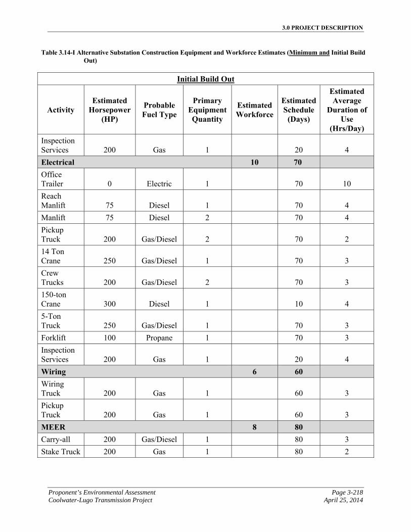
3.0 PROJECT DESCRIPTION
Proponent’s Environmental Assessment Page 3-218 Coolwater-Lugo Transmission Project April 25, 2014
Table 3.14-I Alternative Substation Construction Equipment and Workforce Estimates (Minimum and Initial Build Out)
Initial Build Out
Activity Estimated
Horsepower (HP)
Probable Fuel Type
Primary Equipment Quantity
Estimated Workforce
Estimated Schedule
(Days)
Estimated Average
Duration of Use
(Hrs/Day) Inspection Services 200 Gas 1
20 4
Electrical 10 70 Office Trailer 0 Electric 1
70 10
Reach Manlift 75 Diesel 1
70 4
Manlift 75 Diesel 2 70 4
Pickup Truck 200 Gas/Diesel 2
70 2
14 Ton Crane 250 Gas/Diesel 1
70 3
Crew Trucks 200 Gas/Diesel 2
70 3
150-ton Crane 300 Diesel 1
10 4
5-Ton Truck 250 Gas/Diesel 1
70 3
Forklift 100 Propane 1 70 3
Inspection Services 200 Gas 1
20 4
Wiring 6 60 Wiring Truck 200 Gas 1
60 3
Pickup Truck 200 Gas 1
60 3
MEER 8 80 Carry-all 200 Gas/Diesel 1 80 3
Stake Truck 200 Gas 1 80 2
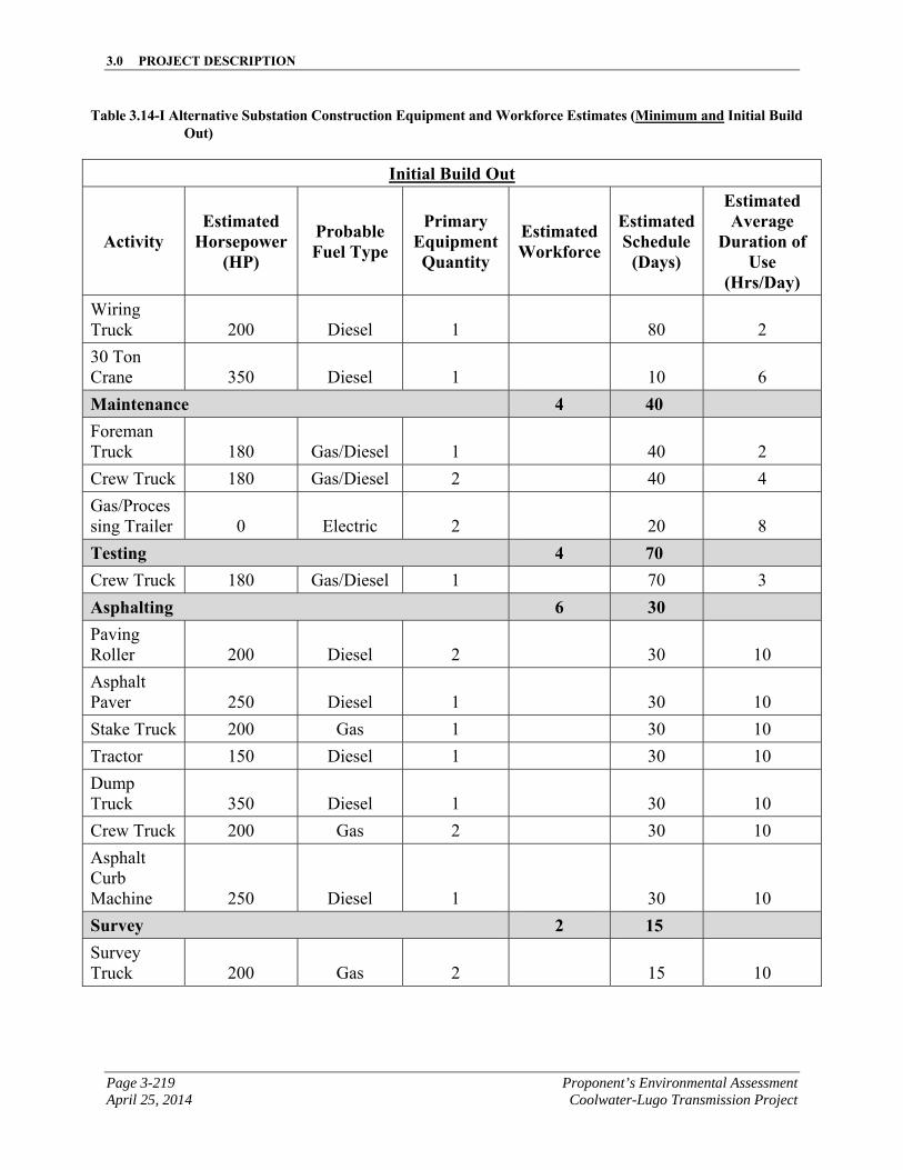
3.0 PROJECT DESCRIPTION
Page 3-219 Proponent’s Environmental Assessment April 25, 2014 Coolwater-Lugo Transmission Project
Table 3.14-I Alternative Substation Construction Equipment and Workforce Estimates (Minimum and Initial Build Out)
Initial Build Out
Activity Estimated
Horsepower (HP)
Probable Fuel Type
Primary Equipment Quantity
Estimated Workforce
Estimated Schedule
(Days)
Estimated Average
Duration of Use
(Hrs/Day) Wiring Truck 200 Diesel 1
80 2
30 Ton Crane 350 Diesel 1
10 6
Maintenance 4 40 Foreman Truck 180 Gas/Diesel 1
40 2
Crew Truck 180 Gas/Diesel 2 40 4
Gas/Processing Trailer 0 Electric 2
20 8
Testing 4 70 Crew Truck 180 Gas/Diesel 1 70 3
Asphalting 6 30 Paving Roller 200 Diesel 2
30 10
Asphalt Paver 250 Diesel 1
30 10
Stake Truck 200 Gas 1 30 10
Tractor 150 Diesel 1 30 10
Dump Truck 350 Diesel 1
30 10
Crew Truck 200 Gas 2 30 10
Asphalt Curb Machine 250 Diesel 1
30 10
Survey 2 15 Survey Truck 200 Gas 2
15 10
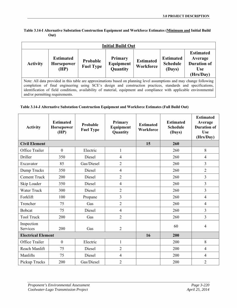
3.0 PROJECT DESCRIPTION
Proponent’s Environmental Assessment Page 3-220 Coolwater-Lugo Transmission Project April 25, 2014
Table 3.14-I Alternative Substation Construction Equipment and Workforce Estimates (Minimum and Initial Build Out)
Initial Build Out
Activity Estimated
Horsepower (HP)
Probable Fuel Type
Primary Equipment Quantity
Estimated Workforce
Estimated Schedule
(Days)
Estimated Average
Duration of Use
(Hrs/Day) Note: All data provided in this table are approximations based on planning level assumptions and may change following completion of final engineering using SCE’s design and construction practices, standards and specifications, identification of field conditions, availability of material, equipment and compliance with applicable environmental and/or permitting requirements.
Table 3.14-J Alternative Substation Construction Equipment and Workforce Estimates (Full Build Out)
Activity Estimated
Horsepower (HP)
Probable Fuel Type
Primary Equipment Quantity
Estimated Workforce
Estimated Schedule
(Days)
Estimated Average
Duration of Use
(Hrs/Day) Civil Element 15 260 Office Trailer 0 Electric 1 260 8
Driller 350 Diesel 4 260 4
Excavator 85 Gas/Diesel 2 260 3
Dump Trucks 350 Diesel 4 260 2
Cement Truck 200 Diesel 2 260 3
Skip Loader 350 Diesel 4 260 3
Water Truck 300 Diesel 2 260 3
Forklift 100 Propane 3 260 4
Trencher 75 Gas 2 260 4
Bobcat 75 Diesel 4 260 3
Tool Truck 200 Gas 2 260 3
Inspection Services 200 Gas 2
60 4
Electrical Element 16 200 Office Trailer 0 Electric 1 200 8
Reach Manlift 75 Diesel 2 200 4
Manlifts 75 Diesel 4 200 4
Pickup Trucks 200 Gas/Diesel 2 200 2
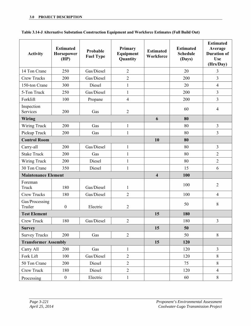
3.0 PROJECT DESCRIPTION
Page 3-221 Proponent’s Environmental Assessment April 25, 2014 Coolwater-Lugo Transmission Project
Table 3.14-J Alternative Substation Construction Equipment and Workforce Estimates (Full Build Out)
Activity Estimated
Horsepower (HP)
Probable Fuel Type
Primary Equipment Quantity
Estimated Workforce
Estimated Schedule
(Days)
Estimated Average
Duration of Use
(Hrs/Day) 14 Ton Crane 250 Gas/Diesel 2 20 3
Crew Trucks 200 Gas/Diesel 2 200 3
150-ton Crane 300 Diesel 1 20 4
5-Ton Truck 250 Gas/Diesel 1 200 3
Forklift 100 Propane 4 200 3
Inspection Services 200 Gas 2
60 4
Wiring 6 80 Wiring Truck 200 Gas 1 80 3
Pickup Truck 200 Gas 1 80 3
Control Room 10 80 Carry-all 200 Gas/Diesel 1 80 3
Stake Truck 200 Gas 1 80 2
Wiring Truck 200 Diesel 1 80 2
30 Ton Crane 350 Diesel 1 15 6
Maintenance Element 4 100 Foreman Truck 180 Gas/Diesel 1
100 2
Crew Trucks 180 Gas/Diesel 2 100 4
Gas/Processing Trailer 0 Electric 2
50 8
Test Element 15 180 Crew Truck 180 Gas/Diesel 2 180 3
Survey 15 50 Survey Trucks 200 Gas 2 50 8
Transformer Assembly 15 120 Carry All 200 Gas 1 120 3
Fork Lift 100 Gas/Diesel 2 120 8
50 Ton Crane 200 Diesel 2 75 8
Crew Truck 180 Diesel 2 120 4
Processing 0 Electric 1 60 8
3.0 PROJECT DESCRIPTION
Proponent’s Environmental Assessment Page 3-222 Coolwater-Lugo Transmission Project April 25, 2014
Table 3.14-J Alternative Substation Construction Equipment and Workforce Estimates (Full Build Out)
Activity Estimated
Horsepower (HP)
Probable Fuel Type
Primary Equipment Quantity
Estimated Workforce
Estimated Schedule
(Days)
Estimated Average
Duration of Use
(Hrs/Day) Trailer
Note: All data provided in this table are approximations based on planning level assumptions and may change following completion of final engineering using SCE’s design and construction practices, standards and specifications, identification of field conditions, availability of material, equipment and compliance with applicable environmental and/or permitting requirements.
3.0 PROJECT DESCRIPTION
Page 3-223 Proponent’s Environmental Assessment April 25, 2014 Coolwater-Lugo Transmission Project
3.14.7.4 Modifications to Existing Substations Description
The modifications at existing substations would be the same for the Alternative Project as described for the Proposed Project in Section 3.1.2, Modifications to Existing Substations Description.
3.14.8 Alternative Transmission Line Installation
The following sections describe the construction activities associated with installing the transmission segments for the Alternative Project, where different from what was described for the Proposed Project.
3.14.8.1 Access and Spur Roads
Where required, a network of existing access roads could be improved and new roads would be constructed to current SCE road practices to support the construction and maintenance of the Alternative Transmission Line Route. Construction activities for access and spur roads for the Alternative Transmission Line Route installation would be the same as described for the Proposed Project, in Section 3.2.3.1, Access and Spur Roads.
The alternative access roads generally follow the Alternative Transmission Line Route. The alternative road system includes spur roads to individual towers where the access road would need to deviate from the Alternative Transmission Line Route due to terrain considerations and topographic constraints.
The alternative transmission route utilizes Segment 12, Segment 2, and Segment 5, which were described as part of the Proposed Project. The following discussion only describes those segments unique to the alternative transmission route (Segments 11, 9/10, 8, 4, 5B, and 6).
Access roads for Segment 12 would be as described for the Proposed Project.
Starting at the southern end of Segment 18, approximately 1.8 miles of new access road would be constructed and existing roads would be improved along the Alternative Transmission Line Segment 11. Access would be accomplished by utilizing a network of existing and proposed spur roads and through access roads that would start at the north-easterly corner of the intersection of Power Line Road and Camp Rock Road and follow the Alternative Transmission Line Route southerly to about 1,300 feet southeasterly from the intersection of Pendleton Road and “A” Street, in the community of Daggett.
Approximately 10.3 miles of new access road would be constructed and portions of existing roads would be improved as needed along the Alternative Transmission Line Segment 9. Access would be accomplished by utilizing a network of existing and proposed spur roads and through access roads that would start about 1,300 feet southeasterly from the intersection of Pendleton Road and “A” Street, in the community of Daggett and would continue along the Alternative Transmission Line Route in a
3.0 PROJECT DESCRIPTION
Proponent’s Environmental Assessment Page 3-224 Coolwater-Lugo Transmission Project April 25, 2014
westerly to southerly direction through the Marine Corps Logistics Base Barstow to a point located approximately 2.0 miles south of the intersection of SR-247 and Veterans Parkway.
Segment 10 is an alternative segment that could be used instead of Segment 9 to avoid crossing Marine Corps Logistics Base Barstow property. If Segment 10 were used, Segment 9 would not be used as part of the Alternative Transmission Line Route. Approximately 11.0 miles of new access road would be constructed and portions of existing roads would be improved as needed along the Alternative Transmission Line Segment 10. Access would be accomplished by utilizing a network of existing and proposed spur roads and through access roads that would start about 1,300 feet southeasterly from the intersection of Pendleton Road and “A” Street, in the community of Daggett and would continue along Segment 10 south and westerly to a point located approximately 2.0 miles south of the intersection of SR-247 and Veterans Parkway.
Approximately 6.2 miles of new access road would be constructed and portions of existing roads would be improved as needed along the Alternative Transmission Line Segment 8. Access would be accomplished by utilizing a network of existing and proposed spur roads and through access roads that would start approximately 2.0 miles south of the intersection of SR-247 and Veterans Parkway and would continue southerly paralleling Segment 8 to the intersection of the LADWP corridor and Stoddard Wells Road.
Access roads for Segment 2 would be as described for the Proposed Project.
Approximately 6.4 miles of new access road would be constructed and portions of existing roads would be improved as needed along the Alternative Transmission Line Segment 4. Access would be accomplished by utilizing a network of existing and proposed spur roads and through access roads that would start at the intersection of SR-247 and Lucerne Valley Cutoff, and would continue south paralleling the Alternative Transmission Line Route to a point approximately 2,800 feet northwest of the intersection of Haynes Road and SR-247.
Approximately 8.4 miles of new access road would be constructed and portions of existing roads would be improved as needed along the Alternative Transmission Line Segment 5 and 5B. Access roads for Segment 5 would be the same as described for the Proposed Project. Access for Segment 5B would be accomplished by utilizing a network of existing and proposed spur roads and through access roads that would start just west of the intersection of Desert View Road and Milpas Drive, and extend southwest to a point just west of the intersection of Laguna Seca Drive and Powerline Road. From here access would continue northwest to the east side of Alternative Desert View Substation.
Approximately 20.1 miles of new access road would be constructed and portions of existing roads would be improved as needed along the Alternative Transmission Line Segment 6. Access would be accomplished by utilizing a network of existing and proposed spur roads and through access roads that would start at the Alternative Desert View Substation, located at the intersection of the northeast corner of Japatul Road and
3.0 PROJECT DESCRIPTION
Page 3-225 Proponent’s Environmental Assessment April 25, 2014 Coolwater-Lugo Transmission Project
Desert View Road, and continue south paralleling the Alternative Transmission Line Route and would meander along Bowen Ranch Road, and then turn westerly once reaching the existing SCE 500 kV ROW where it would continue westerly along the southerly foothills of Juniper Flats, through the Ord Mountains to existing Lugo Substation.
Transmission Line Route Segment ID Access Road Length (miles)
12 1.5
11 1.8
9/10 10.3/11.0
8 6.2
2 7.2
4 6.4
5 and 5B 8.4
6 20.1
Total Miles of Access Road, with Segment 9 61.9 Total Miles of Access Road, with Segment 10 62.6
3.14.8.2 Retaining Walls
Retaining walls and slope stability improvements may also be required for access road and/or transmission line components for the Alternative Transmission Line Route as described for the Proposed Project, in Section 3.2.3.1, Access and Spur Roads. For the purposes of the environmental analysis, it is estimated that Segment 6 would have approximately 8,500 feet of potential retaining wall structures, with each individual wall ranging from approximately 35 to 3,400 feet in length, with an anticipated weighted average exposed height of 17 feet.1 The extent of slope stability improvements and earth retaining walls are determined during final engineering after site-specific reviews and topographic surveys are performed.
Construction methods for any potential retaining walls or slope stability improvements for the Alternative Project would be the same as described for the Proposed Project in Section 3.2.3.2, Retaining Walls.
3.14.8.3 Guard Structures
The Alternative Transmission Line Route with Segment 9 would include installation of temporary guard structures at transportation, flood control, and utility crossings for wire stringing/removal activities. These structures are designed to stop the movement of a
1 Seventeen feet is a weighted average height calculated by dividing the estimated surface face area of the walls by the total wall length. The actual wall heights would be determined during final engineering.
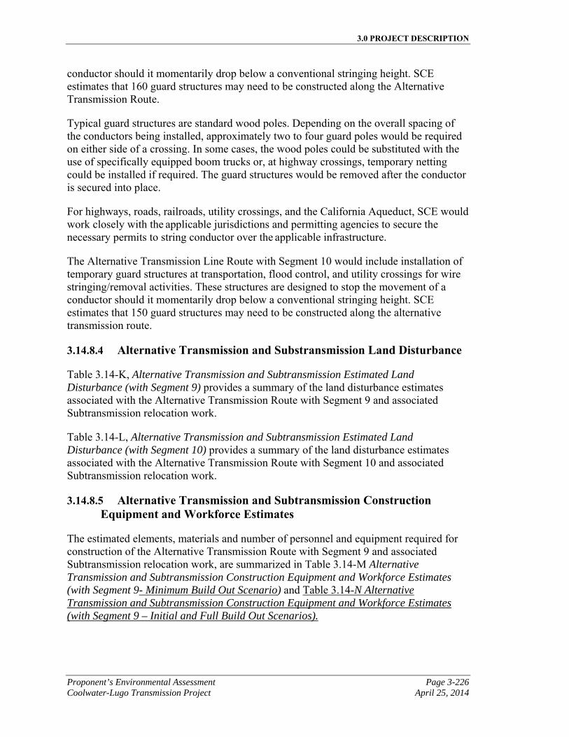
3.0 PROJECT DESCRIPTION
Proponent’s Environmental Assessment Page 3-226 Coolwater-Lugo Transmission Project April 25, 2014
conductor should it momentarily drop below a conventional stringing height. SCE estimates that 160 guard structures may need to be constructed along the Alternative Transmission Route.
Typical guard structures are standard wood poles. Depending on the overall spacing of the conductors being installed, approximately two to four guard poles would be required on either side of a crossing. In some cases, the wood poles could be substituted with the use of specifically equipped boom trucks or, at highway crossings, temporary netting could be installed if required. The guard structures would be removed after the conductor is secured into place.
For highways, roads, railroads, utility crossings, and the California Aqueduct, SCE would work closely with the applicable jurisdictions and permitting agencies to secure the necessary permits to string conductor over the applicable infrastructure.
The Alternative Transmission Line Route with Segment 10 would include installation of temporary guard structures at transportation, flood control, and utility crossings for wire stringing/removal activities. These structures are designed to stop the movement of a conductor should it momentarily drop below a conventional stringing height. SCE estimates that 150 guard structures may need to be constructed along the alternative transmission route.
3.14.8.4 Alternative Transmission and Substransmission Land Disturbance
Table 3.14-K, Alternative Transmission and Subtransmission Estimated Land Disturbance (with Segment 9) provides a summary of the land disturbance estimates associated with the Alternative Transmission Route with Segment 9 and associated Subtransmission relocation work.
Table 3.14-L, Alternative Transmission and Subtransmission Estimated Land Disturbance (with Segment 10) provides a summary of the land disturbance estimates associated with the Alternative Transmission Route with Segment 10 and associated Subtransmission relocation work.
3.14.8.5 Alternative Transmission and Subtransmission Construction Equipment and Workforce Estimates
The estimated elements, materials and number of personnel and equipment required for construction of the Alternative Transmission Route with Segment 9 and associated Subtransmission relocation work, are summarized in Table 3.14-M Alternative Transmission and Subtransmission Construction Equipment and Workforce Estimates (with Segment 9- Minimum Build Out Scenario) and Table 3.14-N Alternative Transmission and Subtransmission Construction Equipment and Workforce Estimates (with Segment 9 – Initial and Full Build Out Scenarios).
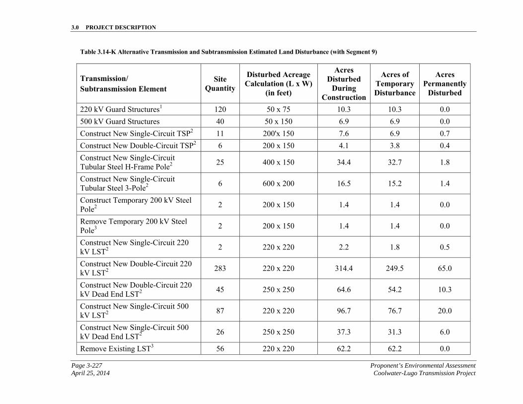
3.0 PROJECT DESCRIPTION
Page 3-227 Proponent’s Environmental Assessment April 25, 2014 Coolwater-Lugo Transmission Project
Table 3.14-K Alternative Transmission and Subtransmission Estimated Land Disturbance (with Segment 9)
Transmission/ Subtransmission Element
Site Quantity
Disturbed Acreage Calculation (L x W)
(in feet)
Acres Disturbed
During Construction
Acres of Temporary Disturbance
Acres Permanently
Disturbed
220 kV Guard Structures1 120 50 x 75 10.3 10.3 0.0
500 kV Guard Structures 40 50 x 150 6.9 6.9 0.0
Construct New Single-Circuit TSP2 11 200'x 150 7.6 6.9 0.7
Construct New Double-Circuit TSP2 6 200 x 150 4.1 3.8 0.4
Construct New Single-Circuit Tubular Steel H-Frame Pole2
25 400 x 150 34.4 32.7 1.8
Construct New Single-Circuit Tubular Steel 3-Pole2
6 600 x 200 16.5 15.2 1.4
Construct Temporary 200 kV Steel Pole2
2 200 x 150 1.4 1.4 0.0
Remove Temporary 200 kV Steel Pole3
2 200 x 150 1.4 1.4 0.0
Construct New Single-Circuit 220 kV LST2
2 220 x 220 2.2 1.8 0.5
Construct New Double-Circuit 220 kV LST2
283 220 x 220 314.4 249.5 65.0
Construct New Double-Circuit 220 kV Dead End LST2
45 250 x 250 64.6 54.2 10.3
Construct New Single-Circuit 500 kV LST2
87 220 x 220 96.7 76.7 20.0
Construct New Single-Circuit 500 kV Dead End LST2
26 250 x 250 37.3 31.3 6.0
Remove Existing LST3 56 220 x 220 62.2 62.2 0.0
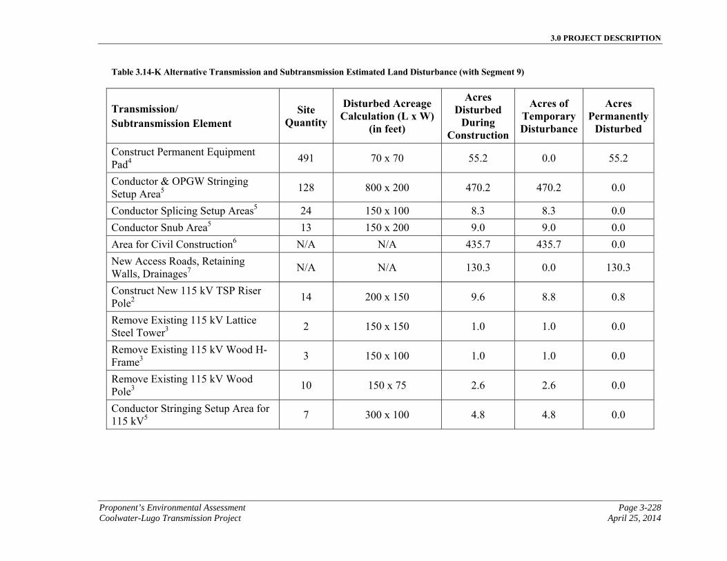
3.0 PROJECT DESCRIPTION
Proponent’s Environmental Assessment Page 3-228 Coolwater-Lugo Transmission Project April 25, 2014
Table 3.14-K Alternative Transmission and Subtransmission Estimated Land Disturbance (with Segment 9)
Transmission/ Subtransmission Element
Site Quantity
Disturbed Acreage Calculation (L x W)
(in feet)
Acres Disturbed
During Construction
Acres of Temporary Disturbance
Acres Permanently
Disturbed
Construct Permanent Equipment Pad4
491 70 x 70 55.2 0.0 55.2
Conductor & OPGW Stringing Setup Area5
128 800 x 200 470.2 470.2 0.0
Conductor Splicing Setup Areas5 24 150 x 100 8.3 8.3 0.0
Conductor Snub Area5 13 150 x 200 9.0 9.0 0.0
Area for Civil Construction6 N/A N/A 435.7 435.7 0.0
New Access Roads, Retaining Walls, Drainages7
N/A N/A 130.3 0.0 130.3
Construct New 115 kV TSP Riser Pole2
14 200 x 150 9.6 8.8 0.8
Remove Existing 115 kV Lattice Steel Tower3
2 150 x 150 1.0 1.0 0.0
Remove Existing 115 kV Wood H-Frame3
3 150 x 100 1.0 1.0 0.0
Remove Existing 115 kV Wood Pole3
10 150 x 75 2.6 2.6 0.0
Conductor Stringing Setup Area for 115 kV5
7 300 x 100 4.8 4.8 0.0
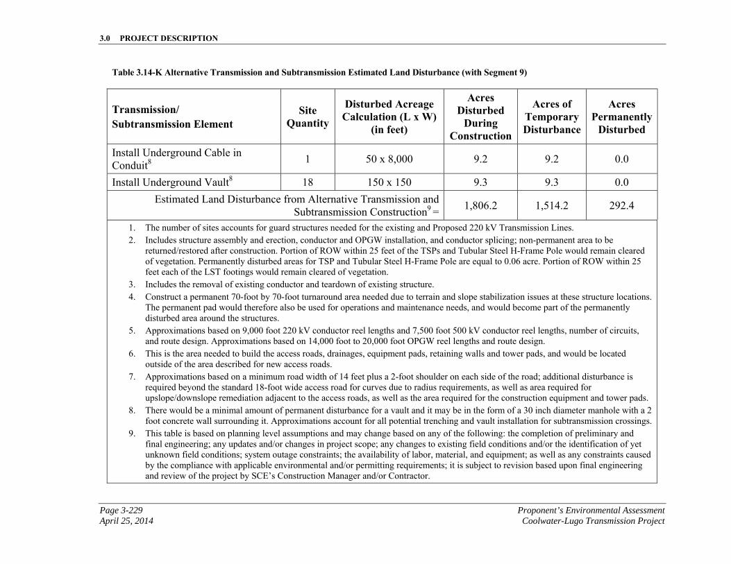
3.0 PROJECT DESCRIPTION
Page 3-229 Proponent’s Environmental Assessment April 25, 2014 Coolwater-Lugo Transmission Project
Table 3.14-K Alternative Transmission and Subtransmission Estimated Land Disturbance (with Segment 9)
Transmission/ Subtransmission Element
Site Quantity
Disturbed Acreage Calculation (L x W)
(in feet)
Acres Disturbed
During Construction
Acres of Temporary Disturbance
Acres Permanently
Disturbed
Install Underground Cable in Conduit8
1 50 x 8,000 9.2 9.2 0.0
Install Underground Vault8 18 150 x 150 9.3 9.3 0.0
Estimated Land Disturbance from Alternative Transmission and Subtransmission Construction9 =
1,806.2 1,514.2 292.4
1. The number of sites accounts for guard structures needed for the existing and Proposed 220 kV Transmission Lines. 2. Includes structure assembly and erection, conductor and OPGW installation, and conductor splicing; non-permanent area to be
returned/restored after construction. Portion of ROW within 25 feet of the TSPs and Tubular Steel H-Frame Pole would remain cleared of vegetation. Permanently disturbed areas for TSP and Tubular Steel H-Frame Pole are equal to 0.06 acre. Portion of ROW within 25 feet each of the LST footings would remain cleared of vegetation.
3. Includes the removal of existing conductor and teardown of existing structure. 4. Construct a permanent 70-foot by 70-foot turnaround area needed due to terrain and slope stabilization issues at these structure locations.
The permanent pad would therefore also be used for operations and maintenance needs, and would become part of the permanently disturbed area around the structures.
5. Approximations based on 9,000 foot 220 kV conductor reel lengths and 7,500 foot 500 kV conductor reel lengths, number of circuits, and route design. Approximations based on 14,000 foot to 20,000 foot OPGW reel lengths and route design.
6. This is the area needed to build the access roads, drainages, equipment pads, retaining walls and tower pads, and would be located outside of the area described for new access roads.
7. Approximations based on a minimum road width of 14 feet plus a 2-foot shoulder on each side of the road; additional disturbance is required beyond the standard 18-foot wide access road for curves due to radius requirements, as well as area required for upslope/downslope remediation adjacent to the access roads, as well as the area required for the construction equipment and tower pads.
8. There would be a minimal amount of permanent disturbance for a vault and it may be in the form of a 30 inch diameter manhole with a 2 foot concrete wall surrounding it. Approximations account for all potential trenching and vault installation for subtransmission crossings.
9. This table is based on planning level assumptions and may change based on any of the following: the completion of preliminary and final engineering; any updates and/or changes in project scope; any changes to existing field conditions and/or the identification of yet unknown field conditions; system outage constraints; the availability of labor, material, and equipment; as well as any constraints caused by the compliance with applicable environmental and/or permitting requirements; it is subject to revision based upon final engineering and review of the project by SCE’s Construction Manager and/or Contractor.
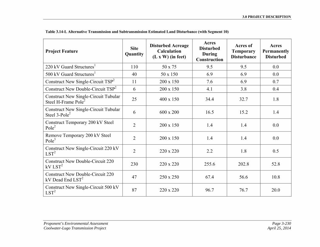
3.0 PROJECT DESCRIPTION
Proponent’s Environmental Assessment Page 3-230 Coolwater-Lugo Transmission Project April 25, 2014
Table 3.14-L Alternative Transmission and Subtransmission Estimated Land Disturbance (with Segment 10)
Project Feature Site Quantity
Disturbed Acreage Calculation
(L x W) (in feet)
Acres Disturbed
During Construction
Acres of Temporary Disturbance
Acres Permanently
Disturbed
220 kV Guard Structures1 110 50 x 75 9.5 9.5 0.0
500 kV Guard Structures1 40 50 x 150 6.9 6.9 0.0
Construct New Single-Circuit TSP2 11 200 x 150 7.6 6.9 0.7
Construct New Double-Circuit TSP2 6 200 x 150 4.1 3.8 0.4
Construct New Single-Circuit Tubular Steel H-Frame Pole2
25 400 x 150 34.4 32.7 1.8
Construct New Single-Circuit Tubular Steel 3-Pole2
6 600 x 200 16.5 15.2 1.4
Construct Temporary 200 kV Steel Pole2
2 200 x 150 1.4 1.4 0.0
Remove Temporary 200 kV Steel Pole3
2 200 x 150 1.4 1.4 0.0
Construct New Single-Circuit 220 kV LST2
2 220 x 220 2.2 1.8 0.5
Construct New Double-Circuit 220 kV LST2
230 220 x 220 255.6 202.8 52.8
Construct New Double-Circuit 220 kV Dead End LST2
47 250 x 250 67.4 56.6 10.8
Construct New Single-Circuit 500 kV LST2
87 220 x 220 96.7 76.7 20.0
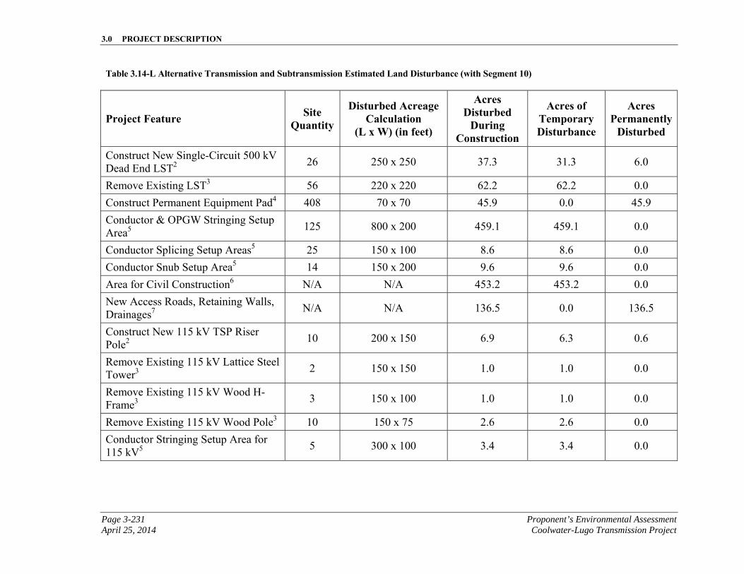
3.0 PROJECT DESCRIPTION
Page 3-231 Proponent’s Environmental Assessment April 25, 2014 Coolwater-Lugo Transmission Project
Table 3.14-L Alternative Transmission and Subtransmission Estimated Land Disturbance (with Segment 10)
Project Feature Site Quantity
Disturbed Acreage Calculation
(L x W) (in feet)
Acres Disturbed
During Construction
Acres of Temporary Disturbance
Acres Permanently
Disturbed
Construct New Single-Circuit 500 kV Dead End LST2
26 250 x 250 37.3 31.3 6.0
Remove Existing LST3 56 220 x 220 62.2 62.2 0.0
Construct Permanent Equipment Pad4 408 70 x 70 45.9 0.0 45.9
Conductor & OPGW Stringing Setup Area5
125 800 x 200 459.1 459.1 0.0
Conductor Splicing Setup Areas5 25 150 x 100 8.6 8.6 0.0
Conductor Snub Setup Area5 14 150 x 200 9.6 9.6 0.0
Area for Civil Construction6 N/A N/A 453.2 453.2 0.0
New Access Roads, Retaining Walls, Drainages7
N/A N/A 136.5 0.0 136.5
Construct New 115 kV TSP Riser Pole2
10 200 x 150 6.9 6.3 0.6
Remove Existing 115 kV Lattice Steel Tower3
2 150 x 150 1.0 1.0 0.0
Remove Existing 115 kV Wood H-Frame3
3 150 x 100 1.0 1.0 0.0
Remove Existing 115 kV Wood Pole3 10 150 x 75 2.6 2.6 0.0
Conductor Stringing Setup Area for 115 kV5
5 300 x 100 3.4 3.4 0.0
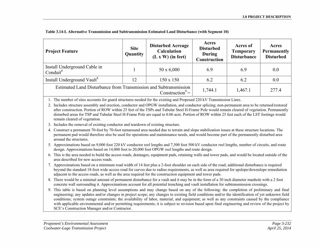
3.0 PROJECT DESCRIPTION
Proponent’s Environmental Assessment Page 3-232 Coolwater-Lugo Transmission Project April 25, 2014
Table 3.14-L Alternative Transmission and Subtransmission Estimated Land Disturbance (with Segment 10)
Project Feature Site Quantity
Disturbed Acreage Calculation
(L x W) (in feet)
Acres Disturbed
During Construction
Acres of Temporary Disturbance
Acres Permanently
Disturbed
Install Underground Cable in Conduit8
1 50 x 6,000 6.9 6.9 0.0
Install Underground Vault8 12 150 x 150 6.2 6.2 0.0
Estimated Land Disturbance from Transmission and Subtransmission Construction9 =
1,744.1 1,467.1 277.4
1. The number of sites accounts for guard structures needed for the existing and Proposed 220 kV Transmission Lines. 2. Includes structure assembly and erection, conductor and OPGW installation, and conductor splicing; non-permanent area to be returned/restored
after construction. Portion of ROW within 25 feet of the TSPs and Tubular Steel H-Frame Pole would remain cleared of vegetation. Permanently disturbed areas for TSP and Tubular Steel H-Frame Pole are equal to 0.06 acre. Portion of ROW within 25 feet each of the LST footings would remain cleared of vegetation.
3. Includes the removal of existing conductor and teardown of existing structure. 4. Construct a permanent 70-foot by 70-foot turnaround area needed due to terrain and slope stabilization issues at these structure locations. The
permanent pad would therefore also be used for operations and maintenance needs, and would become part of the permanently disturbed area around the structures.
5. Approximations based on 9,000 foot 220 kV conductor reel lengths and 7,500 foot 500 kV conductor reel lengths, number of circuits, and route design. Approximations based on 14,000 foot to 20,000 foot OPGW reel lengths and route design.
6. This is the area needed to build the access roads, drainages, equipment pads, retaining walls and tower pads, and would be located outside of the area described for new access roads.
7. Approximations based on a minimum road width of 14 feet plus a 2-foot shoulder on each side of the road; additional disturbance is required beyond the standard 18-foot wide access road for curves due to radius requirements, as well as area required for upslope/downslope remediation adjacent to the access roads, as well as the area required for the construction equipment and tower pads.
8. There would be a minimal amount of permanent disturbance for a vault and it may be in the form of a 30 inch diameter manhole with a 2 foot concrete wall surrounding it. Approximations account for all potential trenching and vault installation for subtransmission crossings.
9. This table is based on planning level assumptions and may change based on any of the following: the completion of preliminary and final engineering; any updates and/or changes in project scope; any changes to existing field conditions and/or the identification of yet unknown field conditions; system outage constraints; the availability of labor, material, and equipment; as well as any constraints caused by the compliance with applicable environmental and/or permitting requirements; it is subject to revision based upon final engineering and review of the project by SCE’s Construction Manager and/or Contractor.
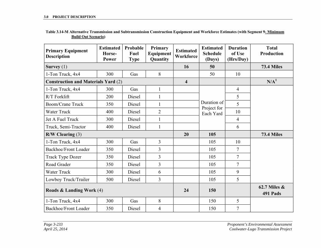
3.0 PROJECT DESCRIPTION
Page 3-233 Proponent’s Environmental Assessment April 25, 2014 Coolwater-Lugo Transmission Project
Table 3.14-M Alternative Transmission and Subtransmission Construction Equipment and Workforce Estimates (with Segment 9- Minimum Build Out Scenario)
Primary Equipment Description
EstimatedHorse-Power
ProbableFuel Type
Primary EquipmentQuantity
Estimated Workforce
EstimatedSchedule
(Days)
Duration of Use
(Hrs/Day)
Total Production
Survey (1) 16 50 73.4 Miles 1-Ton Truck, 4x4 300 Gas 8 50 10
Construction and Materials Yard (2) 4 N/A1 1-Ton Truck, 4x4 300 Gas 1
Duration of Project for Each Yard
4
R/T Forklift 200 Diesel 1 5
Boom/Crane Truck 350 Diesel 1 5
Water Truck 400 Diesel 2 10
Jet A Fuel Truck 300 Diesel 1 4
Truck, Semi-Tractor 400 Diesel 1 6
R/W Clearing (3) 20 105 73.4 Miles 1-Ton Truck, 4x4 300 Gas 3 105 10
Backhoe/Front Loader 350 Diesel 3 105 7
Track Type Dozer 350 Diesel 3 105 7
Road Grader 350 Diesel 3 105 7
Water Truck 300 Diesel 6 105 9
Lowboy Truck/Trailer 500 Diesel 3 105 5
Roads & Landing Work (4) 24 150 62.7 Miles & 491 Pads
1-Ton Truck, 4x4 300 Gas 8 150 5
Backhoe/Front Loader 350 Diesel 4 150 7
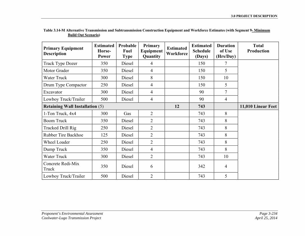
3.0 PROJECT DESCRIPTION
Proponent’s Environmental Assessment Page 3-234 Coolwater-Lugo Transmission Project April 25, 2014
Table 3.14-M Alternative Transmission and Subtransmission Construction Equipment and Workforce Estimates (with Segment 9- Minimum Build Out Scenario)
Primary Equipment Description
EstimatedHorse-Power
ProbableFuel Type
Primary EquipmentQuantity
Estimated Workforce
EstimatedSchedule
(Days)
Duration of Use
(Hrs/Day)
Total Production
Track Type Dozer 350 Diesel 4 150 7
Motor Grader 350 Diesel 4 150 5
Water Truck 300 Diesel 8 150 10
Drum Type Compactor 250 Diesel 4 150 5
Excavator 300 Diesel 4 90 7
Lowboy Truck/Trailer 500 Diesel 4 90 4
Retaining Wall Installation (5) 12 743 11,010 Linear Feet1-Ton Truck, 4x4 300 Gas 2 743 8
Boom Truck 350 Diesel 2 743 8
Tracked Drill Rig 250 Diesel 2 743 8
Rubber Tire Backhoe 125 Diesel 2 743 8
Wheel Loader 250 Diesel 2 743 8
Dump Truck 350 Diesel 4 743 8
Water Truck 300 Diesel 2 743 10
Concrete Redi-Mix Truck
350 Diesel 6 342 4
Lowboy Truck/Trailer 500 Diesel 2 743 5
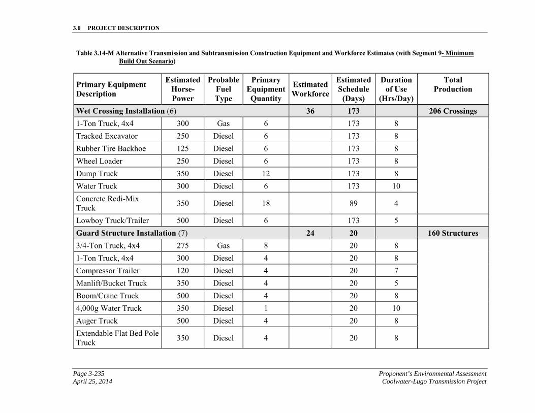
3.0 PROJECT DESCRIPTION
Page 3-235 Proponent’s Environmental Assessment April 25, 2014 Coolwater-Lugo Transmission Project
Table 3.14-M Alternative Transmission and Subtransmission Construction Equipment and Workforce Estimates (with Segment 9- Minimum Build Out Scenario)
Primary Equipment Description
EstimatedHorse-Power
ProbableFuel Type
Primary EquipmentQuantity
Estimated Workforce
EstimatedSchedule
(Days)
Duration of Use
(Hrs/Day)
Total Production
Wet Crossing Installation (6) 36 173 206 Crossings 1-Ton Truck, 4x4 300 Gas 6 173 8
Tracked Excavator 250 Diesel 6 173 8
Rubber Tire Backhoe 125 Diesel 6 173 8
Wheel Loader 250 Diesel 6 173 8
Dump Truck 350 Diesel 12 173 8
Water Truck 300 Diesel 6 173 10
Concrete Redi-Mix Truck
350 Diesel 18 89 4
Lowboy Truck/Trailer 500 Diesel 6 173 5
Guard Structure Installation (7) 24 20 160 Structures 3/4-Ton Truck, 4x4 275 Gas 8 20 8
1-Ton Truck, 4x4 300 Diesel 4 20 8
Compressor Trailer 120 Diesel 4 20 7
Manlift/Bucket Truck 350 Diesel 4 20 5
Boom/Crane Truck 500 Diesel 4 20 8
4,000g Water Truck 350 Diesel 1 20 10
Auger Truck 500 Diesel 4 20 8
Extendable Flat Bed Pole Truck
350 Diesel 4 20 8
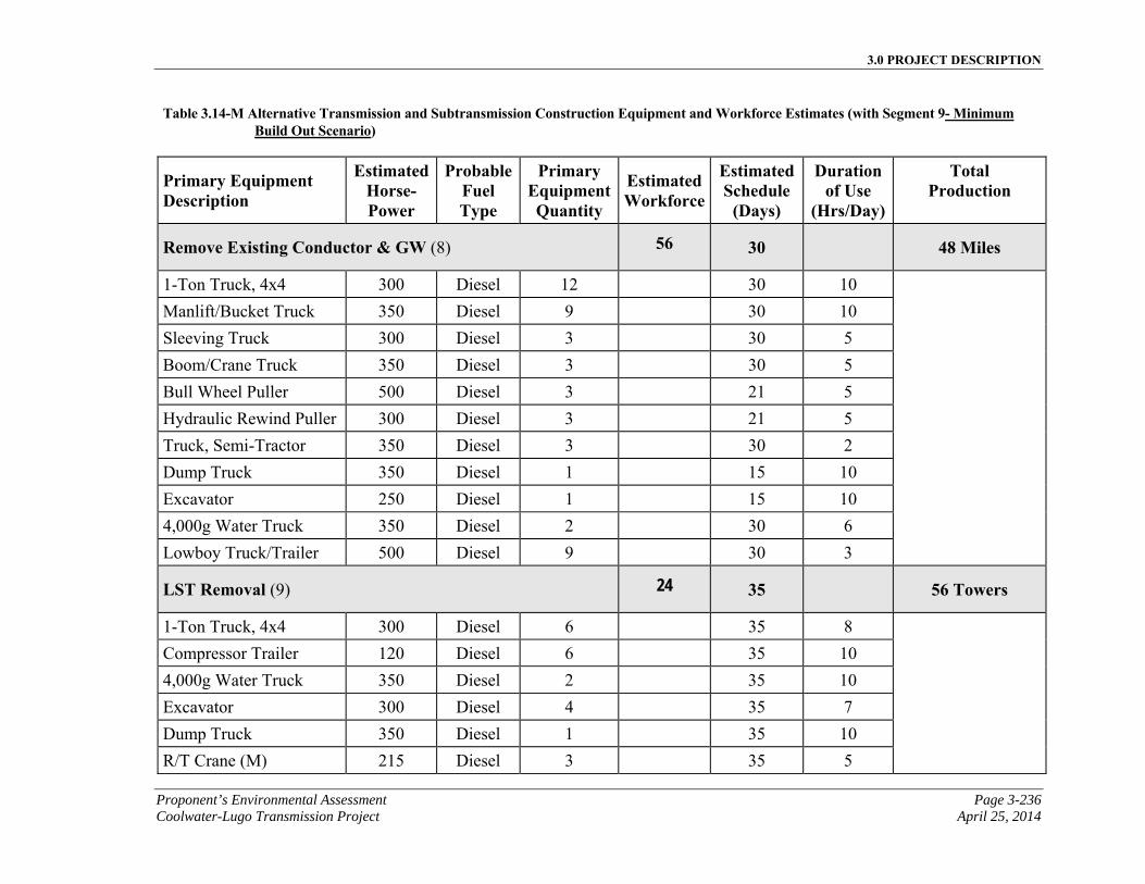
3.0 PROJECT DESCRIPTION
Proponent’s Environmental Assessment Page 3-236 Coolwater-Lugo Transmission Project April 25, 2014
Table 3.14-M Alternative Transmission and Subtransmission Construction Equipment and Workforce Estimates (with Segment 9- Minimum Build Out Scenario)
Primary Equipment Description
EstimatedHorse-Power
ProbableFuel Type
Primary EquipmentQuantity
Estimated Workforce
EstimatedSchedule
(Days)
Duration of Use
(Hrs/Day)
Total Production
Remove Existing Conductor & GW (8) 56 30 48 Miles
1-Ton Truck, 4x4 300 Diesel 12 30 10
Manlift/Bucket Truck 350 Diesel 9 30 10
Sleeving Truck 300 Diesel 3 30 5
Boom/Crane Truck 350 Diesel 3 30 5
Bull Wheel Puller 500 Diesel 3 21 5
Hydraulic Rewind Puller 300 Diesel 3 21 5
Truck, Semi-Tractor 350 Diesel 3 30 2
Dump Truck 350 Diesel 1 15 10
Excavator 250 Diesel 1 15 10
4,000g Water Truck 350 Diesel 2 30 6
Lowboy Truck/Trailer 500 Diesel 9 30 3
LST Removal (9) 24 35 56 Towers
1-Ton Truck, 4x4 300 Diesel 6 35 8
Compressor Trailer 120 Diesel 6 35 10
4,000g Water Truck 350 Diesel 2 35 10
Excavator 300 Diesel 4 35 7
Dump Truck 350 Diesel 1 35 10
R/T Crane (M) 215 Diesel 3 35 5

3.0 PROJECT DESCRIPTION
Page 3-237 Proponent’s Environmental Assessment April 25, 2014 Coolwater-Lugo Transmission Project
Table 3.14-M Alternative Transmission and Subtransmission Construction Equipment and Workforce Estimates (with Segment 9- Minimum Build Out Scenario)
Primary Equipment Description
EstimatedHorse-Power
ProbableFuel Type
Primary EquipmentQuantity
Estimated Workforce
EstimatedSchedule
(Days)
Duration of Use
(Hrs/Day)
Total Production
R/T Crane (L) 300 Diesel 6 35 7
Flat Bed Truck/Trailer 400 Diesel 3 35 10
LST Foundation Removal (10) 16 15 56 LSTs 3/4-Ton Truck, 4x4 275 Gas 1 15 8
Compressor Trailer 120 Diesel 1 15 10
Water Truck 300 Diesel 1 15 10
Backhoe/Front Loader 350 Diesel 1 15 10
Dump Truck 350 Diesel 1 15 10
Excavator 250 Diesel 1 15 10
Install LST Foundations (11) 28 275 443 LSTs 3/4-Ton Truck, 4x4 275 Gas 8 275 5
Boom/Crane Truck 350 Diesel 4 275 7
Backhoe/Front Loader 200 Diesel 4 275 10
Auger Truck 500 Diesel 4 275 10
4,000g Water Truck 350 Diesel 4 275 10
Kaman K-MAX Jet A 1 30 7
Dump Truck 350 Diesel 8 275 10
Concrete Mixer Truck 425 Diesel 12 275 7
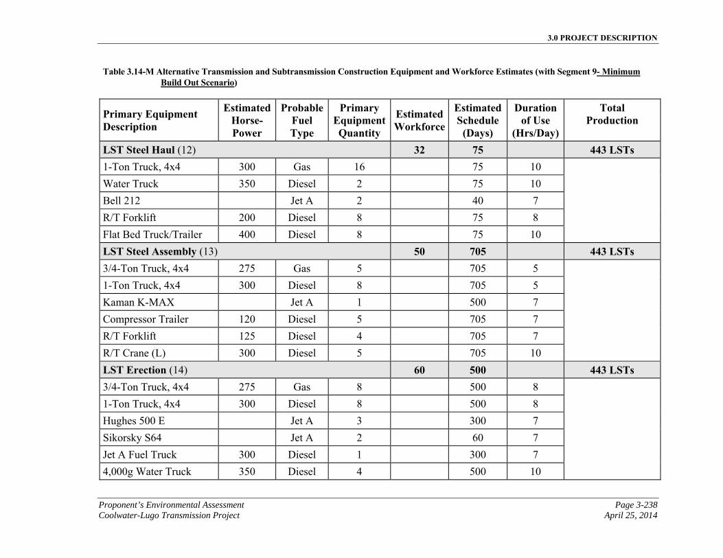
3.0 PROJECT DESCRIPTION
Proponent’s Environmental Assessment Page 3-238 Coolwater-Lugo Transmission Project April 25, 2014
Table 3.14-M Alternative Transmission and Subtransmission Construction Equipment and Workforce Estimates (with Segment 9- Minimum Build Out Scenario)
Primary Equipment Description
EstimatedHorse-Power
ProbableFuel Type
Primary EquipmentQuantity
Estimated Workforce
EstimatedSchedule
(Days)
Duration of Use
(Hrs/Day)
Total Production
LST Steel Haul (12) 32 75 443 LSTs 1-Ton Truck, 4x4 300 Gas 16 75 10
Water Truck 350 Diesel 2 75 10
Bell 212 Jet A 2 40 7
R/T Forklift 200 Diesel 8 75 8
Flat Bed Truck/Trailer 400 Diesel 8 75 10
LST Steel Assembly (13) 50 705 443 LSTs 3/4-Ton Truck, 4x4 275 Gas 5 705 5
1-Ton Truck, 4x4 300 Diesel 8 705 5
Kaman K-MAX Jet A 1 500 7
Compressor Trailer 120 Diesel 5 705 7
R/T Forklift 125 Diesel 4 705 7
R/T Crane (L) 300 Diesel 5 705 10
LST Erection (14) 60 500 443 LSTs 3/4-Ton Truck, 4x4 275 Gas 8 500 8
1-Ton Truck, 4x4 300 Diesel 8 500 8
Hughes 500 E Jet A 3 300 7
Sikorsky S64 Jet A 2 60 7
Jet A Fuel Truck 300 Diesel 1 300 7
4,000g Water Truck 350 Diesel 4 500 10
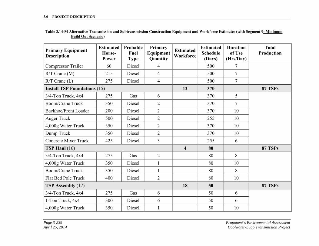
3.0 PROJECT DESCRIPTION
Page 3-239 Proponent’s Environmental Assessment April 25, 2014 Coolwater-Lugo Transmission Project
Table 3.14-M Alternative Transmission and Subtransmission Construction Equipment and Workforce Estimates (with Segment 9- Minimum Build Out Scenario)
Primary Equipment Description
EstimatedHorse-Power
ProbableFuel Type
Primary EquipmentQuantity
Estimated Workforce
EstimatedSchedule
(Days)
Duration of Use
(Hrs/Day)
Total Production
Compressor Trailer 60 Diesel 4 500 7
R/T Crane (M) 215 Diesel 4 500 7
R/T Crane (L) 275 Diesel 4 500 7
Install TSP Foundations (15) 12 370 87 TSPs 3/4-Ton Truck, 4x4 275 Gas 6 370 5
Boom/Crane Truck 350 Diesel 2 370 7
Backhoe/Front Loader 200 Diesel 2 370 10
Auger Truck 500 Diesel 2 255 10
4,000g Water Truck 350 Diesel 2 370 10
Dump Truck 350 Diesel 2 370 10
Concrete Mixer Truck 425 Diesel 3 255 6
TSP Haul (16) 4 80 87 TSPs 3/4-Ton Truck, 4x4 275 Gas 2 80 8
4,000g Water Truck 350 Diesel 1 80 10
Boom/Crane Truck 350 Diesel 1 80 8
Flat Bed Pole Truck 400 Diesel 2 80 10
TSP Assembly (17) 18 50 87 TSPs 3/4-Ton Truck, 4x4 275 Gas 6 50 6
1-Ton Truck, 4x4 300 Diesel 6 50 6
4,000g Water Truck 350 Diesel 1 50 10
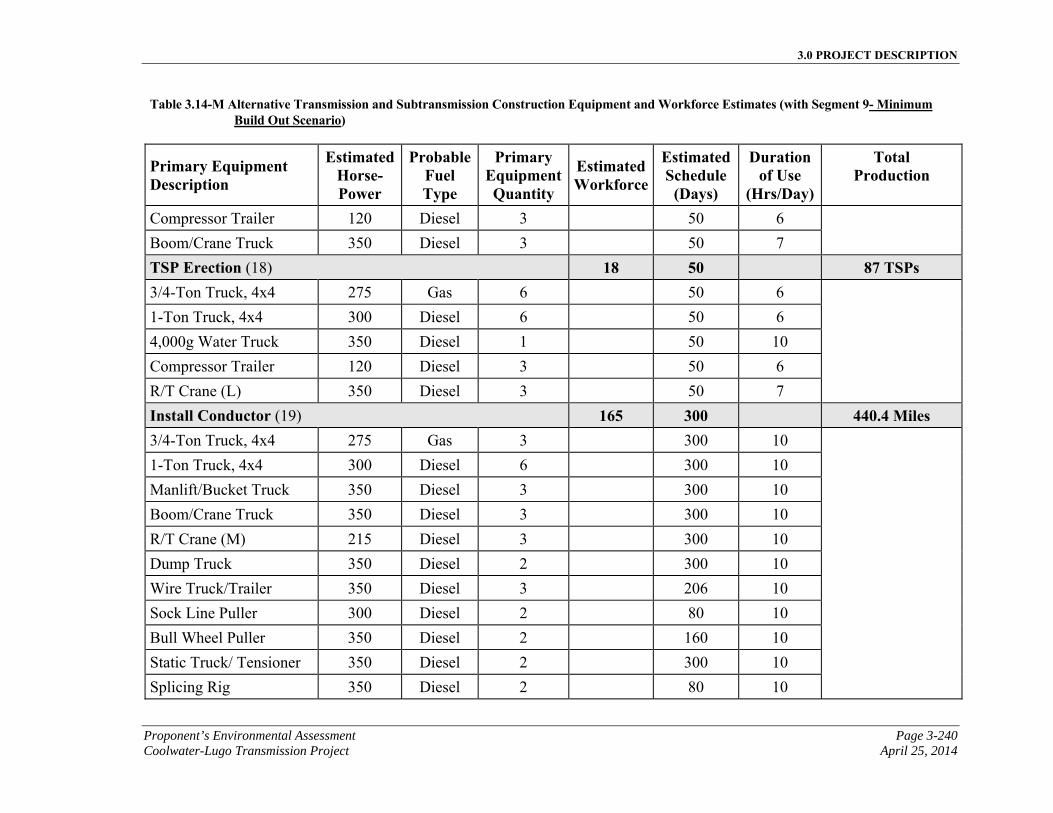
3.0 PROJECT DESCRIPTION
Proponent’s Environmental Assessment Page 3-240 Coolwater-Lugo Transmission Project April 25, 2014
Table 3.14-M Alternative Transmission and Subtransmission Construction Equipment and Workforce Estimates (with Segment 9- Minimum Build Out Scenario)
Primary Equipment Description
EstimatedHorse-Power
ProbableFuel Type
Primary EquipmentQuantity
Estimated Workforce
EstimatedSchedule
(Days)
Duration of Use
(Hrs/Day)
Total Production
Compressor Trailer 120 Diesel 3 50 6
Boom/Crane Truck 350 Diesel 3 50 7
TSP Erection (18) 18 50 87 TSPs 3/4-Ton Truck, 4x4 275 Gas 6 50 6
1-Ton Truck, 4x4 300 Diesel 6 50 6
4,000g Water Truck 350 Diesel 1 50 10
Compressor Trailer 120 Diesel 3 50 6
R/T Crane (L) 350 Diesel 3 50 7
Install Conductor (19) 165 300 440.4 Miles 3/4-Ton Truck, 4x4 275 Gas 3 300 10
1-Ton Truck, 4x4 300 Diesel 6 300 10
Manlift/Bucket Truck 350 Diesel 3 300 10
Boom/Crane Truck 350 Diesel 3 300 10
R/T Crane (M) 215 Diesel 3 300 10
Dump Truck 350 Diesel 2 300 10
Wire Truck/Trailer 350 Diesel 3 206 10
Sock Line Puller 300 Diesel 2 80 10
Bull Wheel Puller 350 Diesel 2 160 10
Static Truck/ Tensioner 350 Diesel 2 300 10
Splicing Rig 350 Diesel 2 80 10
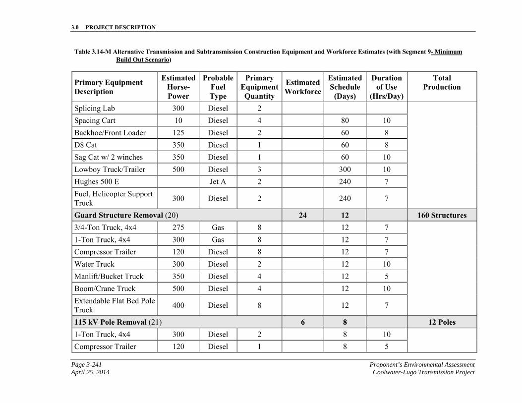
3.0 PROJECT DESCRIPTION
Page 3-241 Proponent’s Environmental Assessment April 25, 2014 Coolwater-Lugo Transmission Project
Table 3.14-M Alternative Transmission and Subtransmission Construction Equipment and Workforce Estimates (with Segment 9- Minimum Build Out Scenario)
Primary Equipment Description
EstimatedHorse-Power
ProbableFuel Type
Primary EquipmentQuantity
Estimated Workforce
EstimatedSchedule
(Days)
Duration of Use
(Hrs/Day)
Total Production
Splicing Lab 300 Diesel 2
Spacing Cart 10 Diesel 4 80 10
Backhoe/Front Loader 125 Diesel 2 60 8
D8 Cat 350 Diesel 1 60 8
Sag Cat w/ 2 winches 350 Diesel 1 60 10
Lowboy Truck/Trailer 500 Diesel 3 300 10
Hughes 500 E Jet A 2 240 7
Fuel, Helicopter Support Truck
300 Diesel 2 240 7
Guard Structure Removal (20) 24 12 160 Structures 3/4-Ton Truck, 4x4 275 Gas 8 12 7
1-Ton Truck, 4x4 300 Gas 8 12 7
Compressor Trailer 120 Diesel 8 12 7
Water Truck 300 Diesel 2 12 10
Manlift/Bucket Truck 350 Diesel 4 12 5
Boom/Crane Truck 500 Diesel 4 12 10
Extendable Flat Bed Pole Truck
400 Diesel 8 12 7
115 kV Pole Removal (21) 6 8 12 Poles 1-Ton Truck, 4x4 300 Diesel 2 8 10
Compressor Trailer 120 Diesel 1 8 5
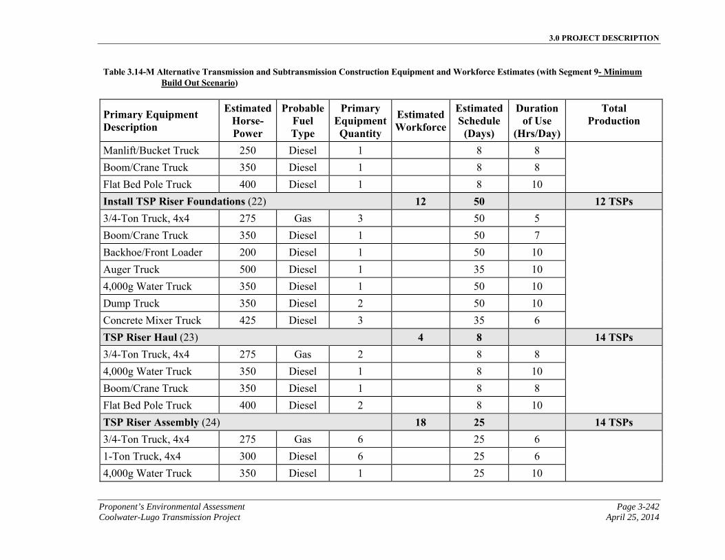
3.0 PROJECT DESCRIPTION
Proponent’s Environmental Assessment Page 3-242 Coolwater-Lugo Transmission Project April 25, 2014
Table 3.14-M Alternative Transmission and Subtransmission Construction Equipment and Workforce Estimates (with Segment 9- Minimum Build Out Scenario)
Primary Equipment Description
EstimatedHorse-Power
ProbableFuel Type
Primary EquipmentQuantity
Estimated Workforce
EstimatedSchedule
(Days)
Duration of Use
(Hrs/Day)
Total Production
Manlift/Bucket Truck 250 Diesel 1 8 8
Boom/Crane Truck 350 Diesel 1 8 8
Flat Bed Pole Truck 400 Diesel 1 8 10
Install TSP Riser Foundations (22) 12 50 12 TSPs 3/4-Ton Truck, 4x4 275 Gas 3 50 5
Boom/Crane Truck 350 Diesel 1 50 7
Backhoe/Front Loader 200 Diesel 1 50 10
Auger Truck 500 Diesel 1 35 10
4,000g Water Truck 350 Diesel 1 50 10
Dump Truck 350 Diesel 2 50 10
Concrete Mixer Truck 425 Diesel 3 35 6
TSP Riser Haul (23) 4 8 14 TSPs 3/4-Ton Truck, 4x4 275 Gas 2 8 8
4,000g Water Truck 350 Diesel 1 8 10
Boom/Crane Truck 350 Diesel 1 8 8
Flat Bed Pole Truck 400 Diesel 2 8 10
TSP Riser Assembly (24) 18 25 14 TSPs 3/4-Ton Truck, 4x4 275 Gas 6 25 6
1-Ton Truck, 4x4 300 Diesel 6 25 6
4,000g Water Truck 350 Diesel 1 25 10
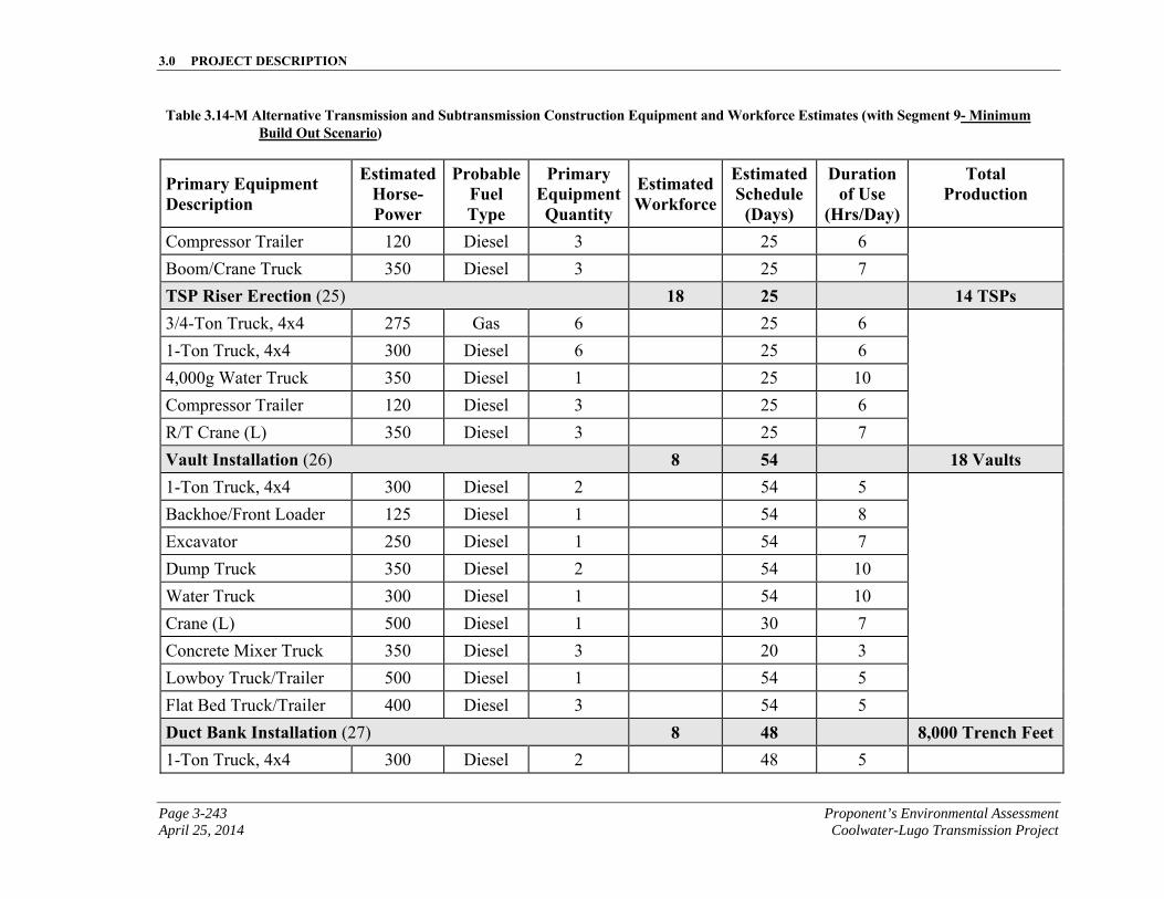
3.0 PROJECT DESCRIPTION
Page 3-243 Proponent’s Environmental Assessment April 25, 2014 Coolwater-Lugo Transmission Project
Table 3.14-M Alternative Transmission and Subtransmission Construction Equipment and Workforce Estimates (with Segment 9- Minimum Build Out Scenario)
Primary Equipment Description
EstimatedHorse-Power
ProbableFuel Type
Primary EquipmentQuantity
Estimated Workforce
EstimatedSchedule
(Days)
Duration of Use
(Hrs/Day)
Total Production
Compressor Trailer 120 Diesel 3 25 6
Boom/Crane Truck 350 Diesel 3 25 7
TSP Riser Erection (25) 18 25 14 TSPs 3/4-Ton Truck, 4x4 275 Gas 6 25 6
1-Ton Truck, 4x4 300 Diesel 6 25 6
4,000g Water Truck 350 Diesel 1 25 10
Compressor Trailer 120 Diesel 3 25 6
R/T Crane (L) 350 Diesel 3 25 7
Vault Installation (26) 8 54 18 Vaults 1-Ton Truck, 4x4 300 Diesel 2 54 5
Backhoe/Front Loader 125 Diesel 1 54 8
Excavator 250 Diesel 1 54 7
Dump Truck 350 Diesel 2 54 10
Water Truck 300 Diesel 1 54 10
Crane (L) 500 Diesel 1 30 7
Concrete Mixer Truck 350 Diesel 3 20 3
Lowboy Truck/Trailer 500 Diesel 1 54 5
Flat Bed Truck/Trailer 400 Diesel 3 54 5
Duct Bank Installation (27) 8 48 8,000 Trench Feet 1-Ton Truck, 4x4 300 Diesel 2 48 5
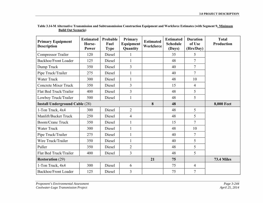
3.0 PROJECT DESCRIPTION
Proponent’s Environmental Assessment Page 3-244 Coolwater-Lugo Transmission Project April 25, 2014
Table 3.14-M Alternative Transmission and Subtransmission Construction Equipment and Workforce Estimates (with Segment 9- Minimum Build Out Scenario)
Primary Equipment Description
EstimatedHorse-Power
ProbableFuel Type
Primary EquipmentQuantity
Estimated Workforce
EstimatedSchedule
(Days)
Duration of Use
(Hrs/Day)
Total Production
Compressor Trailer 120 Diesel 1 35 5
Backhoe/Front Loader 125 Diesel 1 48 7
Dump Truck 350 Diesel 3 40 7
Pipe Truck/Trailer 275 Diesel 1 40 7
Water Truck 300 Diesel 1 48 10
Concrete Mixer Truck 350 Diesel 3 15 4
Flat Bed Truck/Trailer 400 Diesel 3 48 5
Lowboy Truck/Trailer 500 Diesel 1 48 5
Install Underground Cable (28) 8 48 8,000 Feet 1-Ton Truck, 4x4 300 Diesel 2 48 5
Manlift/Bucket Truck 250 Diesel 4 48 5
Boom/Crane Truck 350 Diesel 1 15 7
Water Truck 300 Diesel 1 48 10
Pipe Truck/Trailer 275 Diesel 1 40 7
Wire Truck/Trailer 350 Diesel 1 40 5
Puller 350 Diesel 2 48 5
Flat Bed Truck/Trailer 400 Diesel 3 48 5
Restoration (29) 21 75 73.4 Miles 1-Ton Truck, 4x4 300 Diesel 6 75 4
Backhoe/Front Loader 125 Diesel 3 75 7
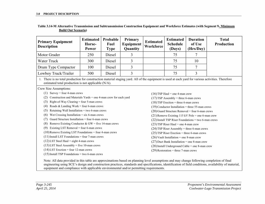
3.0 PROJECT DESCRIPTION
Page 3-245 Proponent’s Environmental Assessment April 25, 2014 Coolwater-Lugo Transmission Project
Table 3.14-M Alternative Transmission and Subtransmission Construction Equipment and Workforce Estimates (with Segment 9- Minimum Build Out Scenario)
Primary Equipment Description
EstimatedHorse-Power
ProbableFuel Type
Primary EquipmentQuantity
Estimated Workforce
EstimatedSchedule
(Days)
Duration of Use
(Hrs/Day)
Total Production
Motor Grader 250 Diesel 3 75 7
Water Truck 300 Diesel 3 75 10
Drum Type Compactor 100 Diesel 3 75 7
Lowboy Truck/Trailer 500 Diesel 3 75 3
1. There is no total production for construction material staging yard. All of the equipment is used at each yard for various activities. Therefore estimated total production is not applicable (N/A).
Crew Size Assumptions: (1) Survey = four 4-man crews (2) Construction and Materials Yards = one 4-man crew for each yard (3) Right-of-Way Clearing = four 5-man crews (4) Roads & Landing Work = four 6-man crews (5) Retaining Wall Installation = two 6-man crews (6) Wet Crossing Installation = six 6-man crews (7) Guard Structure Installation = four 6-man crews (8) Remove Existing Conductor & GW = five 14-man crews (9) Existing LST Removal = four 6-man crews (10) Remove Existing LST Foundations = four 4-man crews (11) Install LST Foundations = four 7-man crews (12) LST Steel Haul = eight 4-man crews (13) LST Steel Assembly = five 10-man crews (14) LST Erection = four 12-man crews (15) Install TSP Foundations = two 6-man crews
(16) TSP Haul = one 4-man crew (17) TSP Assembly = three 6-man crews (18) TSP Erection = three 6-man crews (19) Conductor Installation = three 55-man crews (20) Guard Structure Removal = four 6-man crews (21) Remove Existing 115 kV Pole = one 6-man crew (22) Install TSP Riser Foundations = two 6-man crews (23) TSP Riser Haul = one 4-man crew (24) TSP Riser Assembly = three 6-man crews (25) TSP Riser Erection = three 6-man crews (26) Vault Installation = one 8-man crew (27) Duct Bank Installation = one 8-man crew (28) Install Underground Cable = one 8-man crew (29) Restoration = three 7-man crews
Note: All data provided in this table are approximations based on planning level assumptions and may change following completion of final engineering using SCE’s design and construction practices, standards and specifications, identification of field conditions, availability of material, equipment and compliance with applicable environmental and/or permitting requirements.
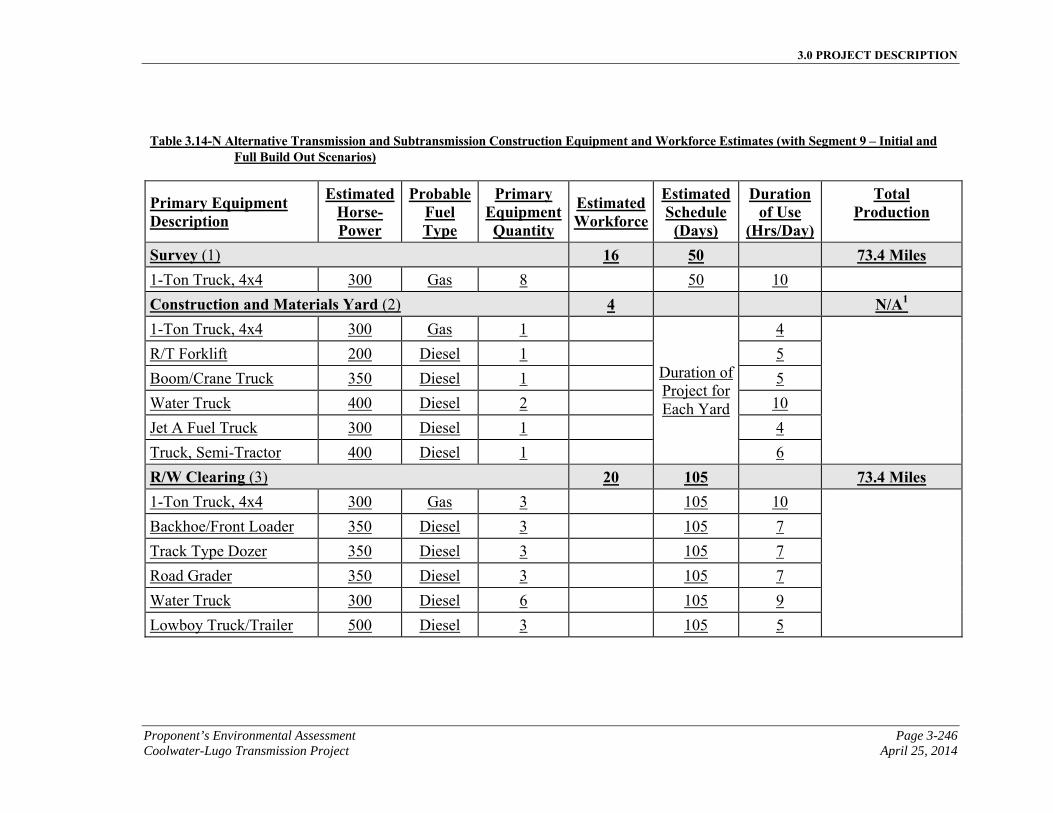
3.0 PROJECT DESCRIPTION
Proponent’s Environmental Assessment Page 3-246 Coolwater-Lugo Transmission Project April 25, 2014
Table 3.14-N Alternative Transmission and Subtransmission Construction Equipment and Workforce Estimates (with Segment 9 – Initial and
Full Build Out Scenarios)
Primary Equipment Description
EstimatedHorse-Power
ProbableFuel Type
Primary EquipmentQuantity
Estimated Workforce
EstimatedSchedule
(Days)
Duration of Use
(Hrs/Day)
Total Production
Survey (1) 16 50 73.4 Miles 1-Ton Truck, 4x4 300 Gas 8 50 10
Construction and Materials Yard (2) 4 N/A1 1-Ton Truck, 4x4 300 Gas 1
Duration of Project for Each Yard
4
R/T Forklift 200 Diesel 1 5
Boom/Crane Truck 350 Diesel 1 5
Water Truck 400 Diesel 2 10
Jet A Fuel Truck 300 Diesel 1 4
Truck, Semi-Tractor 400 Diesel 1 6
R/W Clearing (3) 20 105 73.4 Miles 1-Ton Truck, 4x4 300 Gas 3 105 10
Backhoe/Front Loader 350 Diesel 3 105 7
Track Type Dozer 350 Diesel 3 105 7
Road Grader 350 Diesel 3 105 7
Water Truck 300 Diesel 6 105 9
Lowboy Truck/Trailer 500 Diesel 3 105 5
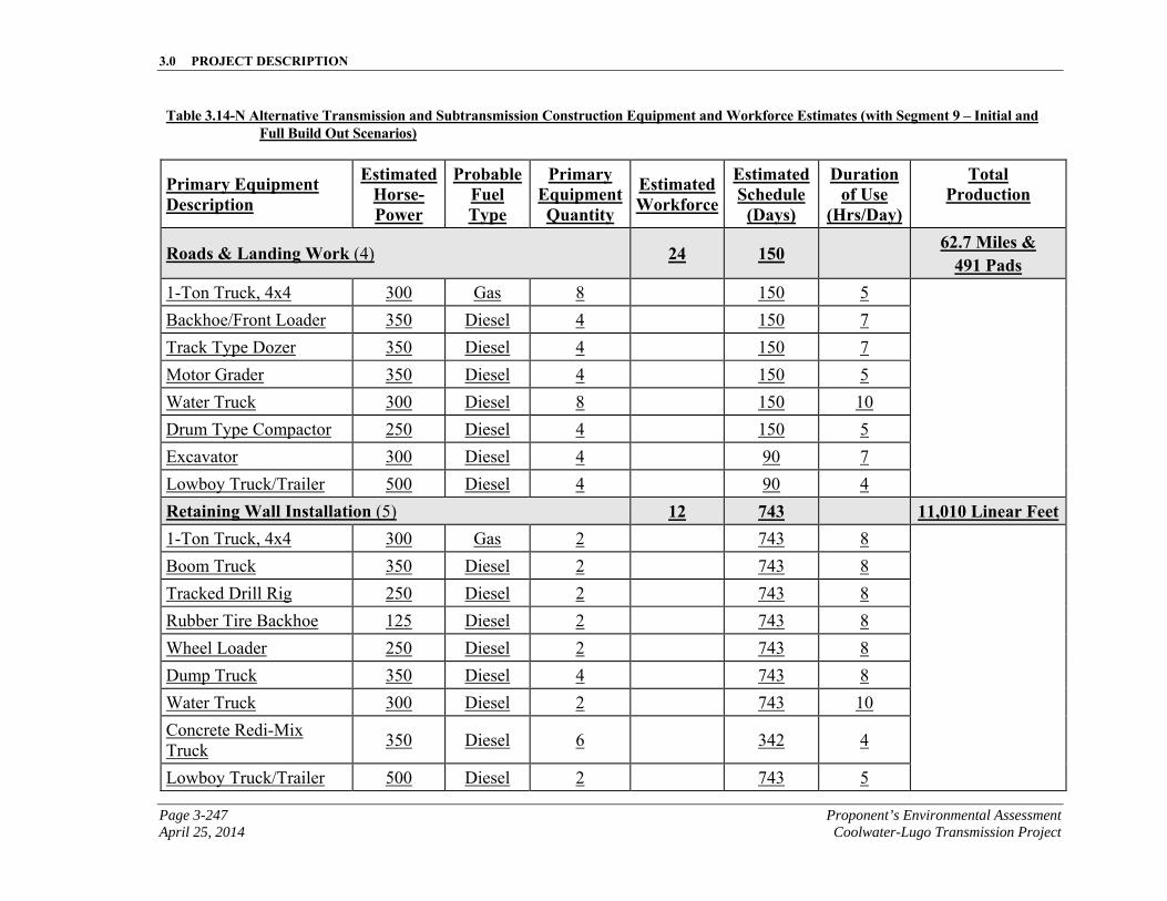
3.0 PROJECT DESCRIPTION
Page 3-247 Proponent’s Environmental Assessment April 25, 2014 Coolwater-Lugo Transmission Project
Table 3.14-N Alternative Transmission and Subtransmission Construction Equipment and Workforce Estimates (with Segment 9 – Initial and Full Build Out Scenarios)
Primary Equipment Description
EstimatedHorse-Power
ProbableFuel Type
Primary EquipmentQuantity
Estimated Workforce
EstimatedSchedule
(Days)
Duration of Use
(Hrs/Day)
Total Production
Roads & Landing Work (4) 24 150 62.7 Miles & 491 Pads
1-Ton Truck, 4x4 300 Gas 8 150 5
Backhoe/Front Loader 350 Diesel 4 150 7
Track Type Dozer 350 Diesel 4 150 7
Motor Grader 350 Diesel 4 150 5
Water Truck 300 Diesel 8 150 10
Drum Type Compactor 250 Diesel 4 150 5
Excavator 300 Diesel 4 90 7
Lowboy Truck/Trailer 500 Diesel 4 90 4
Retaining Wall Installation (5) 12 743 11,010 Linear Feet1-Ton Truck, 4x4 300 Gas 2 743 8
Boom Truck 350 Diesel 2 743 8
Tracked Drill Rig 250 Diesel 2 743 8
Rubber Tire Backhoe 125 Diesel 2 743 8
Wheel Loader 250 Diesel 2 743 8
Dump Truck 350 Diesel 4 743 8
Water Truck 300 Diesel 2 743 10
Concrete Redi-Mix Truck
350 Diesel 6 342 4
Lowboy Truck/Trailer 500 Diesel 2 743 5
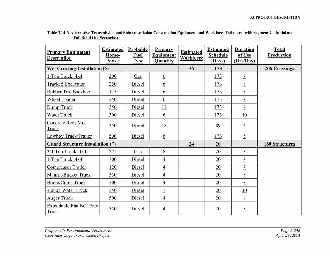
3.0 PROJECT DESCRIPTION
Proponent’s Environmental Assessment Page 3-248 Coolwater-Lugo Transmission Project April 25, 2014
Table 3.14-N Alternative Transmission and Subtransmission Construction Equipment and Workforce Estimates (with Segment 9 – Initial and Full Build Out Scenarios)
Primary Equipment Description
EstimatedHorse-Power
ProbableFuel Type
Primary EquipmentQuantity
Estimated Workforce
EstimatedSchedule
(Days)
Duration of Use
(Hrs/Day)
Total Production
Wet Crossing Installation (6) 36 173 206 Crossings 1-Ton Truck, 4x4 300 Gas 6 173 8
Tracked Excavator 250 Diesel 6 173 8
Rubber Tire Backhoe 125 Diesel 6 173 8
Wheel Loader 250 Diesel 6 173 8
Dump Truck 350 Diesel 12 173 8
Water Truck 300 Diesel 6 173 10
Concrete Redi-Mix Truck
350 Diesel 18 89 4
Lowboy Truck/Trailer 500 Diesel 6 173 5
Guard Structure Installation (7) 24 20 160 Structures 3/4-Ton Truck, 4x4 275 Gas 8 20 8
1-Ton Truck, 4x4 300 Diesel 4 20 8
Compressor Trailer 120 Diesel 4 20 7
Manlift/Bucket Truck 350 Diesel 4 20 5
Boom/Crane Truck 500 Diesel 4 20 8
4,000g Water Truck 350 Diesel 1 20 10
Auger Truck 500 Diesel 4 20 8
Extendable Flat Bed Pole Truck
350 Diesel 4 20 8
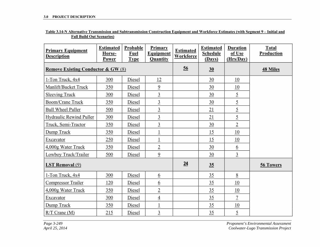
3.0 PROJECT DESCRIPTION
Page 3-249 Proponent’s Environmental Assessment April 25, 2014 Coolwater-Lugo Transmission Project
Table 3.14-N Alternative Transmission and Subtransmission Construction Equipment and Workforce Estimates (with Segment 9 – Initial and Full Build Out Scenarios)
Primary Equipment Description
EstimatedHorse-Power
ProbableFuel Type
Primary EquipmentQuantity
Estimated Workforce
EstimatedSchedule
(Days)
Duration of Use
(Hrs/Day)
Total Production
Remove Existing Conductor & GW (8) 56 30 48 Miles
1-Ton Truck, 4x4 300 Diesel 12 30 10
Manlift/Bucket Truck 350 Diesel 9 30 10
Sleeving Truck 300 Diesel 3 30 5
Boom/Crane Truck 350 Diesel 3 30 5
Bull Wheel Puller 500 Diesel 3 21 5
Hydraulic Rewind Puller 300 Diesel 3 21 5
Truck, Semi-Tractor 350 Diesel 3 30 2
Dump Truck 350 Diesel 1 15 10
Excavator 250 Diesel 1 15 10
4,000g Water Truck 350 Diesel 2 30 6
Lowboy Truck/Trailer 500 Diesel 9 30 3
LST Removal (9) 24 35 56 Towers
1-Ton Truck, 4x4 300 Diesel 6 35 8
Compressor Trailer 120 Diesel 6 35 10
4,000g Water Truck 350 Diesel 2 35 10
Excavator 300 Diesel 4 35 7
Dump Truck 350 Diesel 1 35 10
R/T Crane (M) 215 Diesel 3 35 5
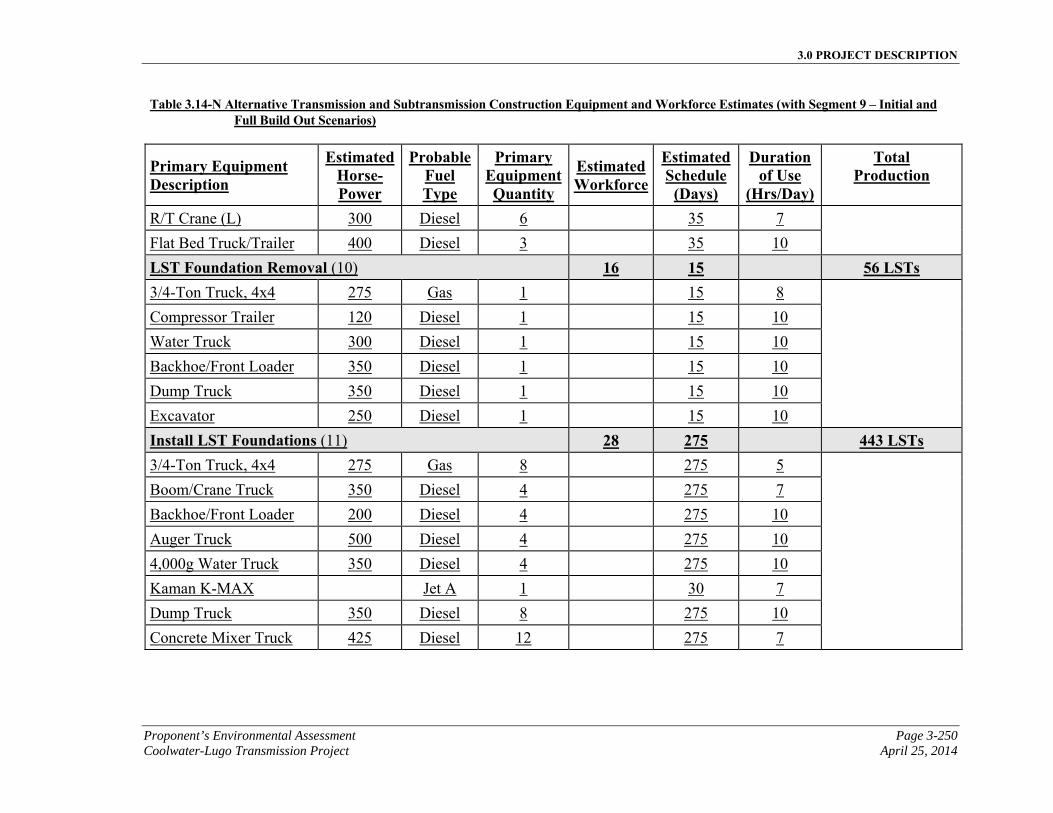
3.0 PROJECT DESCRIPTION
Proponent’s Environmental Assessment Page 3-250 Coolwater-Lugo Transmission Project April 25, 2014
Table 3.14-N Alternative Transmission and Subtransmission Construction Equipment and Workforce Estimates (with Segment 9 – Initial and Full Build Out Scenarios)
Primary Equipment Description
EstimatedHorse-Power
ProbableFuel Type
Primary EquipmentQuantity
Estimated Workforce
EstimatedSchedule
(Days)
Duration of Use
(Hrs/Day)
Total Production
R/T Crane (L) 300 Diesel 6 35 7
Flat Bed Truck/Trailer 400 Diesel 3 35 10
LST Foundation Removal (10) 16 15 56 LSTs 3/4-Ton Truck, 4x4 275 Gas 1 15 8
Compressor Trailer 120 Diesel 1 15 10
Water Truck 300 Diesel 1 15 10
Backhoe/Front Loader 350 Diesel 1 15 10
Dump Truck 350 Diesel 1 15 10
Excavator 250 Diesel 1 15 10
Install LST Foundations (11) 28 275 443 LSTs 3/4-Ton Truck, 4x4 275 Gas 8 275 5
Boom/Crane Truck 350 Diesel 4 275 7
Backhoe/Front Loader 200 Diesel 4 275 10
Auger Truck 500 Diesel 4 275 10
4,000g Water Truck 350 Diesel 4 275 10
Kaman K-MAX Jet A 1 30 7
Dump Truck 350 Diesel 8 275 10
Concrete Mixer Truck 425 Diesel 12 275 7
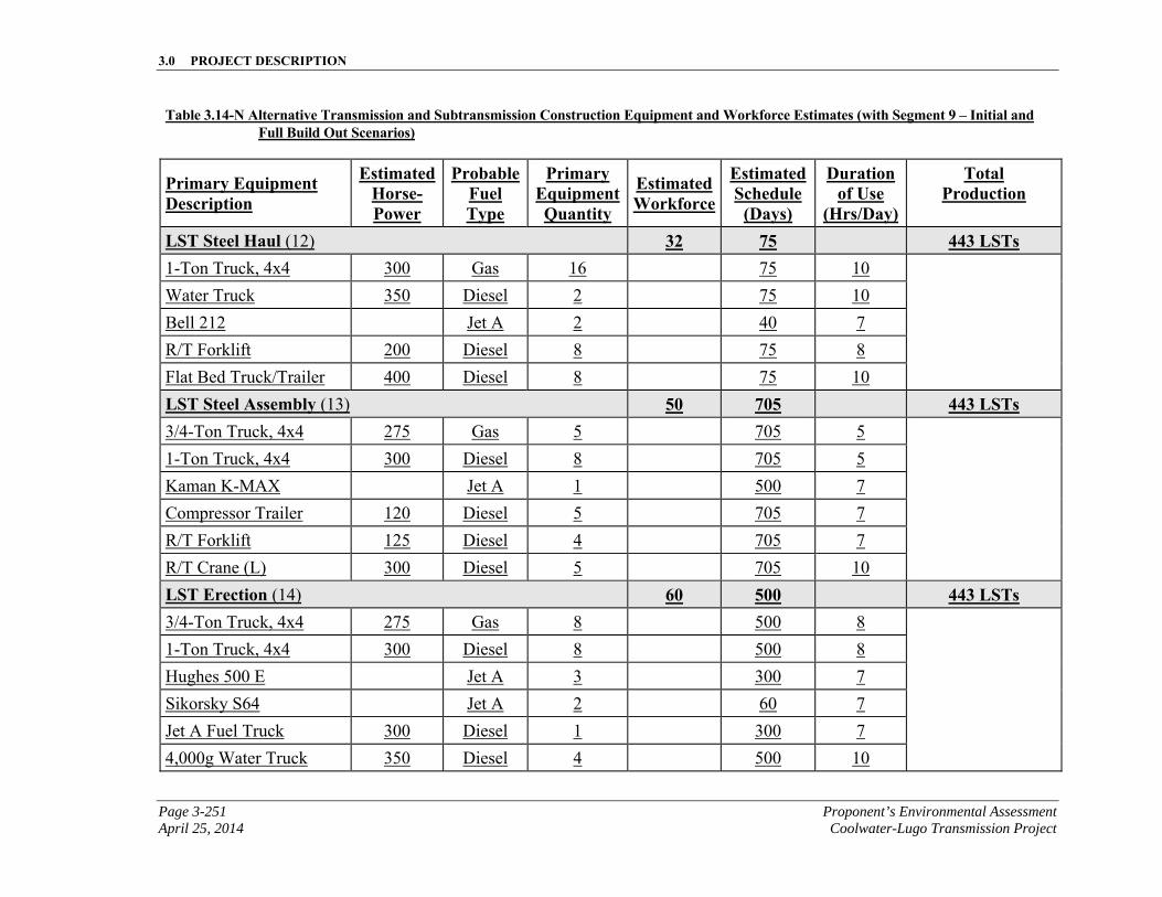
3.0 PROJECT DESCRIPTION
Page 3-251 Proponent’s Environmental Assessment April 25, 2014 Coolwater-Lugo Transmission Project
Table 3.14-N Alternative Transmission and Subtransmission Construction Equipment and Workforce Estimates (with Segment 9 – Initial and Full Build Out Scenarios)
Primary Equipment Description
EstimatedHorse-Power
ProbableFuel Type
Primary EquipmentQuantity
Estimated Workforce
EstimatedSchedule
(Days)
Duration of Use
(Hrs/Day)
Total Production
LST Steel Haul (12) 32 75 443 LSTs 1-Ton Truck, 4x4 300 Gas 16 75 10
Water Truck 350 Diesel 2 75 10
Bell 212 Jet A 2 40 7
R/T Forklift 200 Diesel 8 75 8
Flat Bed Truck/Trailer 400 Diesel 8 75 10
LST Steel Assembly (13) 50 705 443 LSTs 3/4-Ton Truck, 4x4 275 Gas 5 705 5
1-Ton Truck, 4x4 300 Diesel 8 705 5
Kaman K-MAX Jet A 1 500 7
Compressor Trailer 120 Diesel 5 705 7
R/T Forklift 125 Diesel 4 705 7
R/T Crane (L) 300 Diesel 5 705 10
LST Erection (14) 60 500 443 LSTs 3/4-Ton Truck, 4x4 275 Gas 8 500 8
1-Ton Truck, 4x4 300 Diesel 8 500 8
Hughes 500 E Jet A 3 300 7
Sikorsky S64 Jet A 2 60 7
Jet A Fuel Truck 300 Diesel 1 300 7
4,000g Water Truck 350 Diesel 4 500 10
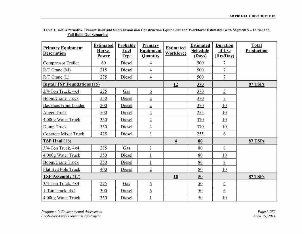
3.0 PROJECT DESCRIPTION
Proponent’s Environmental Assessment Page 3-252 Coolwater-Lugo Transmission Project April 25, 2014
Table 3.14-N Alternative Transmission and Subtransmission Construction Equipment and Workforce Estimates (with Segment 9 – Initial and Full Build Out Scenarios)
Primary Equipment Description
EstimatedHorse-Power
ProbableFuel Type
Primary EquipmentQuantity
Estimated Workforce
EstimatedSchedule
(Days)
Duration of Use
(Hrs/Day)
Total Production
Compressor Trailer 60 Diesel 4 500 7
R/T Crane (M) 215 Diesel 4 500 7
R/T Crane (L) 275 Diesel 4 500 7
Install TSP Foundations (15) 12 370 87 TSPs 3/4-Ton Truck, 4x4 275 Gas 6 370 5
Boom/Crane Truck 350 Diesel 2 370 7
Backhoe/Front Loader 200 Diesel 2 370 10
Auger Truck 500 Diesel 2 255 10
4,000g Water Truck 350 Diesel 2 370 10
Dump Truck 350 Diesel 2 370 10
Concrete Mixer Truck 425 Diesel 3 255 6
TSP Haul (16) 4 80 87 TSPs 3/4-Ton Truck, 4x4 275 Gas 2 80 8
4,000g Water Truck 350 Diesel 1 80 10
Boom/Crane Truck 350 Diesel 1 80 8
Flat Bed Pole Truck 400 Diesel 2 80 10
TSP Assembly (17) 18 50 87 TSPs 3/4-Ton Truck, 4x4 275 Gas 6 50 6
1-Ton Truck, 4x4 300 Diesel 6 50 6
4,000g Water Truck 350 Diesel 1 50 10
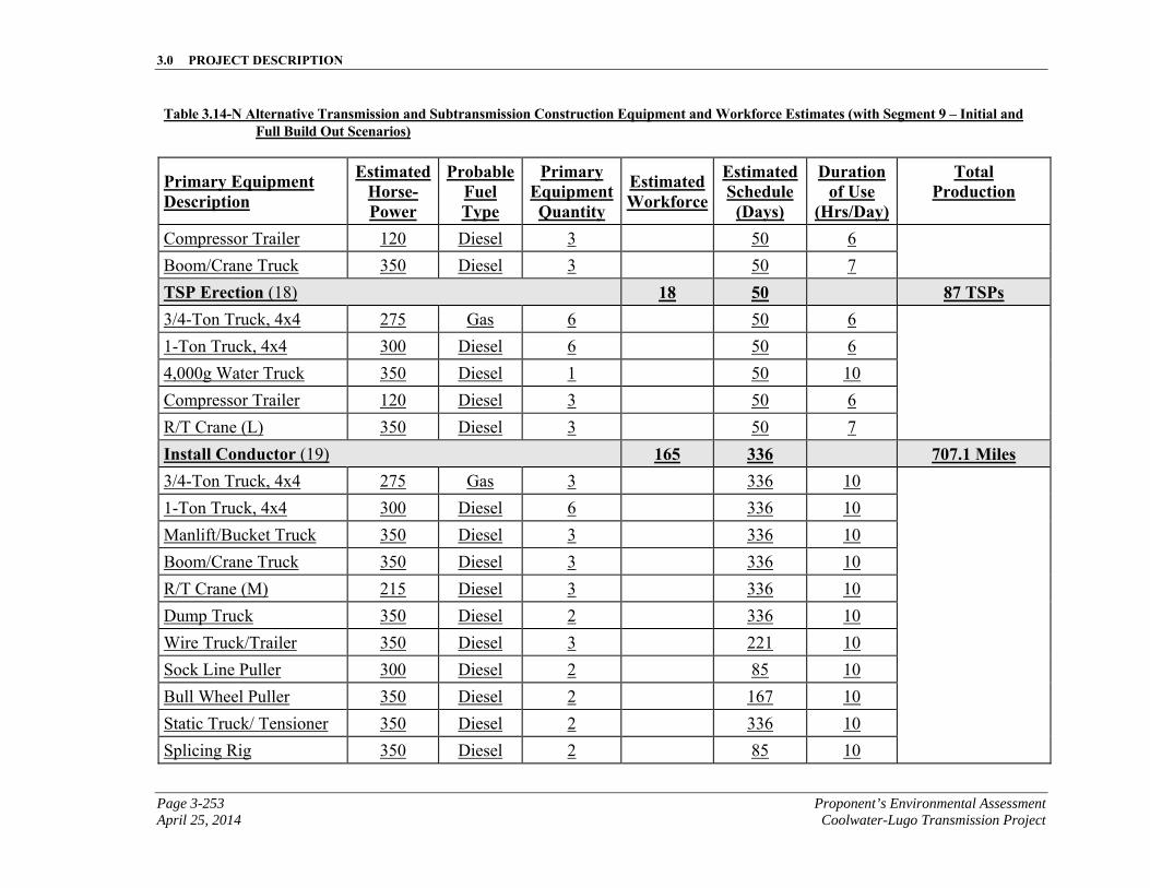
3.0 PROJECT DESCRIPTION
Page 3-253 Proponent’s Environmental Assessment April 25, 2014 Coolwater-Lugo Transmission Project
Table 3.14-N Alternative Transmission and Subtransmission Construction Equipment and Workforce Estimates (with Segment 9 – Initial and Full Build Out Scenarios)
Primary Equipment Description
EstimatedHorse-Power
ProbableFuel Type
Primary EquipmentQuantity
Estimated Workforce
EstimatedSchedule
(Days)
Duration of Use
(Hrs/Day)
Total Production
Compressor Trailer 120 Diesel 3 50 6
Boom/Crane Truck 350 Diesel 3 50 7
TSP Erection (18) 18 50 87 TSPs 3/4-Ton Truck, 4x4 275 Gas 6 50 6
1-Ton Truck, 4x4 300 Diesel 6 50 6
4,000g Water Truck 350 Diesel 1 50 10
Compressor Trailer 120 Diesel 3 50 6
R/T Crane (L) 350 Diesel 3 50 7
Install Conductor (19) 165 336 707.1 Miles 3/4-Ton Truck, 4x4 275 Gas 3 336 10
1-Ton Truck, 4x4 300 Diesel 6 336 10
Manlift/Bucket Truck 350 Diesel 3 336 10
Boom/Crane Truck 350 Diesel 3 336 10
R/T Crane (M) 215 Diesel 3 336 10
Dump Truck 350 Diesel 2 336 10
Wire Truck/Trailer 350 Diesel 3 221 10
Sock Line Puller 300 Diesel 2 85 10
Bull Wheel Puller 350 Diesel 2 167 10
Static Truck/ Tensioner 350 Diesel 2 336 10
Splicing Rig 350 Diesel 2 85 10
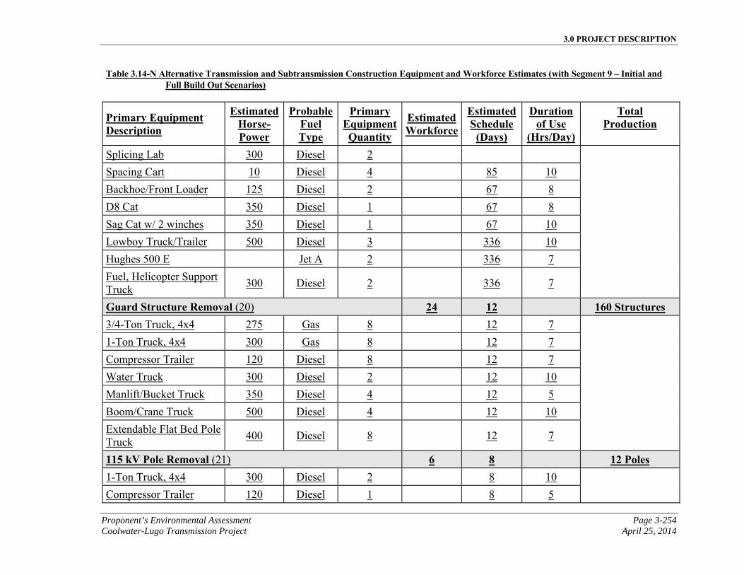
3.0 PROJECT DESCRIPTION
Proponent’s Environmental Assessment Page 3-254 Coolwater-Lugo Transmission Project April 25, 2014
Table 3.14-N Alternative Transmission and Subtransmission Construction Equipment and Workforce Estimates (with Segment 9 – Initial and Full Build Out Scenarios)
Primary Equipment Description
EstimatedHorse-Power
ProbableFuel Type
Primary EquipmentQuantity
Estimated Workforce
EstimatedSchedule
(Days)
Duration of Use
(Hrs/Day)
Total Production
Splicing Lab 300 Diesel 2
Spacing Cart 10 Diesel 4 85 10
Backhoe/Front Loader 125 Diesel 2 67 8
D8 Cat 350 Diesel 1 67 8
Sag Cat w/ 2 winches 350 Diesel 1 67 10
Lowboy Truck/Trailer 500 Diesel 3 336 10
Hughes 500 E Jet A 2 336 7
Fuel, Helicopter Support Truck
300 Diesel 2 336 7
Guard Structure Removal (20) 24 12 160 Structures 3/4-Ton Truck, 4x4 275 Gas 8 12 7
1-Ton Truck, 4x4 300 Gas 8 12 7
Compressor Trailer 120 Diesel 8 12 7
Water Truck 300 Diesel 2 12 10
Manlift/Bucket Truck 350 Diesel 4 12 5
Boom/Crane Truck 500 Diesel 4 12 10
Extendable Flat Bed Pole Truck
400 Diesel 8 12 7
115 kV Pole Removal (21) 6 8 12 Poles 1-Ton Truck, 4x4 300 Diesel 2 8 10
Compressor Trailer 120 Diesel 1 8 5
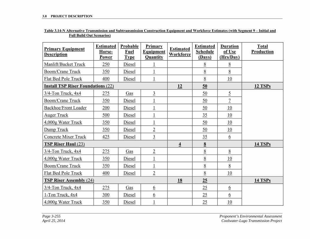
3.0 PROJECT DESCRIPTION
Page 3-255 Proponent’s Environmental Assessment April 25, 2014 Coolwater-Lugo Transmission Project
Table 3.14-N Alternative Transmission and Subtransmission Construction Equipment and Workforce Estimates (with Segment 9 – Initial and Full Build Out Scenarios)
Primary Equipment Description
EstimatedHorse-Power
ProbableFuel Type
Primary EquipmentQuantity
Estimated Workforce
EstimatedSchedule
(Days)
Duration of Use
(Hrs/Day)
Total Production
Manlift/Bucket Truck 250 Diesel 1 8 8
Boom/Crane Truck 350 Diesel 1 8 8
Flat Bed Pole Truck 400 Diesel 1 8 10
Install TSP Riser Foundations (22) 12 50 12 TSPs 3/4-Ton Truck, 4x4 275 Gas 3 50 5
Boom/Crane Truck 350 Diesel 1 50 7
Backhoe/Front Loader 200 Diesel 1 50 10
Auger Truck 500 Diesel 1 35 10
4,000g Water Truck 350 Diesel 1 50 10
Dump Truck 350 Diesel 2 50 10
Concrete Mixer Truck 425 Diesel 3 35 6
TSP Riser Haul (23) 4 8 14 TSPs 3/4-Ton Truck, 4x4 275 Gas 2 8 8
4,000g Water Truck 350 Diesel 1 8 10
Boom/Crane Truck 350 Diesel 1 8 8
Flat Bed Pole Truck 400 Diesel 2 8 10
TSP Riser Assembly (24) 18 25 14 TSPs 3/4-Ton Truck, 4x4 275 Gas 6 25 6
1-Ton Truck, 4x4 300 Diesel 6 25 6
4,000g Water Truck 350 Diesel 1 25 10
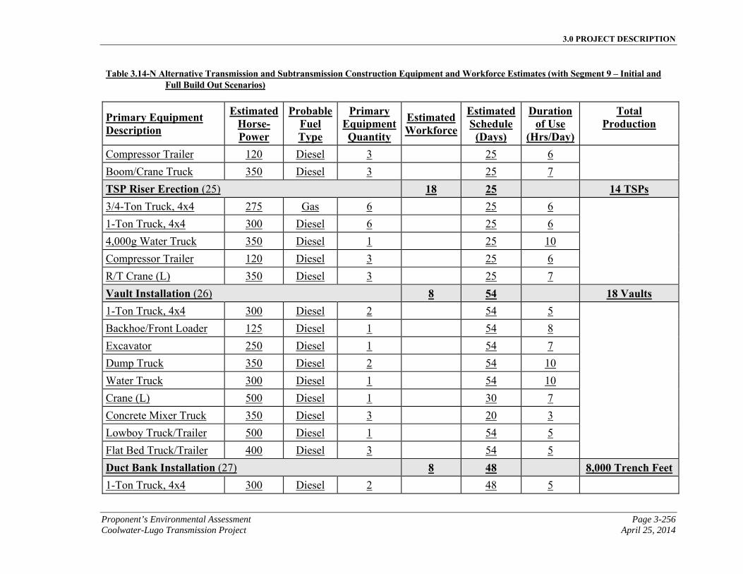
3.0 PROJECT DESCRIPTION
Proponent’s Environmental Assessment Page 3-256 Coolwater-Lugo Transmission Project April 25, 2014
Table 3.14-N Alternative Transmission and Subtransmission Construction Equipment and Workforce Estimates (with Segment 9 – Initial and Full Build Out Scenarios)
Primary Equipment Description
EstimatedHorse-Power
ProbableFuel Type
Primary EquipmentQuantity
Estimated Workforce
EstimatedSchedule
(Days)
Duration of Use
(Hrs/Day)
Total Production
Compressor Trailer 120 Diesel 3 25 6
Boom/Crane Truck 350 Diesel 3 25 7
TSP Riser Erection (25) 18 25 14 TSPs 3/4-Ton Truck, 4x4 275 Gas 6 25 6
1-Ton Truck, 4x4 300 Diesel 6 25 6
4,000g Water Truck 350 Diesel 1 25 10
Compressor Trailer 120 Diesel 3 25 6
R/T Crane (L) 350 Diesel 3 25 7
Vault Installation (26) 8 54 18 Vaults 1-Ton Truck, 4x4 300 Diesel 2 54 5
Backhoe/Front Loader 125 Diesel 1 54 8
Excavator 250 Diesel 1 54 7
Dump Truck 350 Diesel 2 54 10
Water Truck 300 Diesel 1 54 10
Crane (L) 500 Diesel 1 30 7
Concrete Mixer Truck 350 Diesel 3 20 3
Lowboy Truck/Trailer 500 Diesel 1 54 5
Flat Bed Truck/Trailer 400 Diesel 3 54 5
Duct Bank Installation (27) 8 48 8,000 Trench Feet 1-Ton Truck, 4x4 300 Diesel 2 48 5
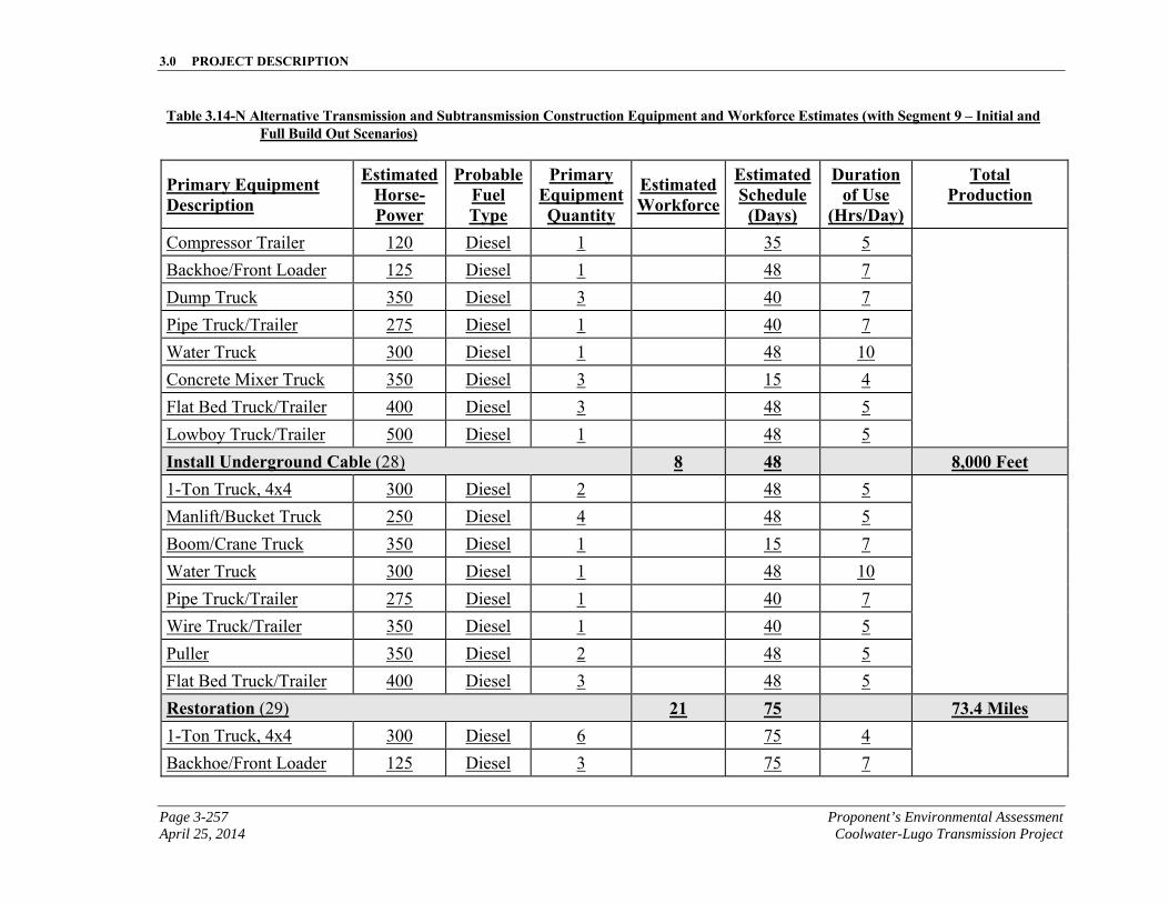
3.0 PROJECT DESCRIPTION
Page 3-257 Proponent’s Environmental Assessment April 25, 2014 Coolwater-Lugo Transmission Project
Table 3.14-N Alternative Transmission and Subtransmission Construction Equipment and Workforce Estimates (with Segment 9 – Initial and Full Build Out Scenarios)
Primary Equipment Description
EstimatedHorse-Power
ProbableFuel Type
Primary EquipmentQuantity
Estimated Workforce
EstimatedSchedule
(Days)
Duration of Use
(Hrs/Day)
Total Production
Compressor Trailer 120 Diesel 1 35 5
Backhoe/Front Loader 125 Diesel 1 48 7
Dump Truck 350 Diesel 3 40 7
Pipe Truck/Trailer 275 Diesel 1 40 7
Water Truck 300 Diesel 1 48 10
Concrete Mixer Truck 350 Diesel 3 15 4
Flat Bed Truck/Trailer 400 Diesel 3 48 5
Lowboy Truck/Trailer 500 Diesel 1 48 5
Install Underground Cable (28) 8 48 8,000 Feet 1-Ton Truck, 4x4 300 Diesel 2 48 5
Manlift/Bucket Truck 250 Diesel 4 48 5
Boom/Crane Truck 350 Diesel 1 15 7
Water Truck 300 Diesel 1 48 10
Pipe Truck/Trailer 275 Diesel 1 40 7
Wire Truck/Trailer 350 Diesel 1 40 5
Puller 350 Diesel 2 48 5
Flat Bed Truck/Trailer 400 Diesel 3 48 5
Restoration (29) 21 75 73.4 Miles 1-Ton Truck, 4x4 300 Diesel 6 75 4
Backhoe/Front Loader 125 Diesel 3 75 7
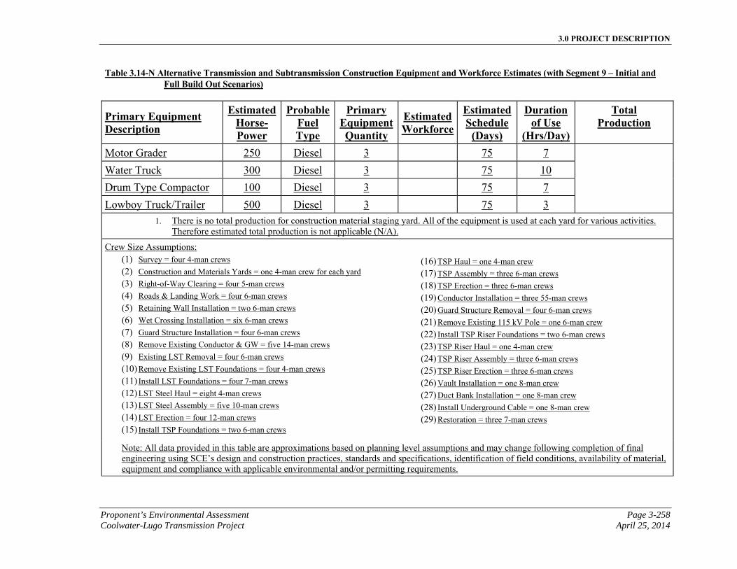
3.0 PROJECT DESCRIPTION
Proponent’s Environmental Assessment Page 3-258 Coolwater-Lugo Transmission Project April 25, 2014
Table 3.14-N Alternative Transmission and Subtransmission Construction Equipment and Workforce Estimates (with Segment 9 – Initial and Full Build Out Scenarios)
Primary Equipment Description
EstimatedHorse-Power
ProbableFuel Type
Primary EquipmentQuantity
Estimated Workforce
EstimatedSchedule
(Days)
Duration of Use
(Hrs/Day)
Total Production
Motor Grader 250 Diesel 3 75 7
Water Truck 300 Diesel 3 75 10
Drum Type Compactor 100 Diesel 3 75 7
Lowboy Truck/Trailer 500 Diesel 3 75 3
1. There is no total production for construction material staging yard. All of the equipment is used at each yard for various activities. Therefore estimated total production is not applicable (N/A).
Crew Size Assumptions: (1) Survey = four 4-man crews (2) Construction and Materials Yards = one 4-man crew for each yard (3) Right-of-Way Clearing = four 5-man crews (4) Roads & Landing Work = four 6-man crews (5) Retaining Wall Installation = two 6-man crews (6) Wet Crossing Installation = six 6-man crews (7) Guard Structure Installation = four 6-man crews (8) Remove Existing Conductor & GW = five 14-man crews (9) Existing LST Removal = four 6-man crews (10) Remove Existing LST Foundations = four 4-man crews (11) Install LST Foundations = four 7-man crews (12) LST Steel Haul = eight 4-man crews (13) LST Steel Assembly = five 10-man crews (14) LST Erection = four 12-man crews (15) Install TSP Foundations = two 6-man crews
(16) TSP Haul = one 4-man crew (17) TSP Assembly = three 6-man crews (18) TSP Erection = three 6-man crews (19) Conductor Installation = three 55-man crews (20) Guard Structure Removal = four 6-man crews (21) Remove Existing 115 kV Pole = one 6-man crew (22) Install TSP Riser Foundations = two 6-man crews (23) TSP Riser Haul = one 4-man crew (24) TSP Riser Assembly = three 6-man crews (25) TSP Riser Erection = three 6-man crews (26) Vault Installation = one 8-man crew (27) Duct Bank Installation = one 8-man crew (28) Install Underground Cable = one 8-man crew (29) Restoration = three 7-man crews
Note: All data provided in this table are approximations based on planning level assumptions and may change following completion of final engineering using SCE’s design and construction practices, standards and specifications, identification of field conditions, availability of material, equipment and compliance with applicable environmental and/or permitting requirements.
3.0 PROJECT DESCRIPTION
Page 3-259 Proponent’s Environmental Assessment April 25, 2014 Coolwater-Lugo Transmission Project
The estimated elements, materials and number of personnel and equipment required for construction of the Alternative Transmission Route with Segment 10 and associated Subtransmission relocation work, , are summarized in Table 3.14-NO Alternative Transmission and Subtransmission Construction Equipment and Workforce Estimates (with Segment 10 – Minimum Build Out Scenario) and Table 3.14-P Alternative Transmission and Subtransmission Construction Equipment and Workforce Estimates (with Segment 10 – Initial and Full Build Out Scenarios).
3.14.8.6 Energizing Alternative Transmission Lines
As with the Proposed Project, energizing the new lines associated with the Alternative Project is the final step in completing the transmission and subtransmission construction. Existing lines would be de-energized as needed, in order to connect the new line segments to the existing system. To reduce the need for electric service interruption, de-energizing and re-energizing the existing lines may occur at night when electrical demand is low.
3.14.8.7 Alternative Project Other Major Work
The cellular site relocations described for the Proposed Project would not be required as part of the Alternative Project, based on the location of cellular sites on existing structures at this time.
3.14.8.8 Alternative Project Telecommunication Construction
The construction activities for the telecommunication path associated with the Alternative Project would be the same as described for the Proposed Project, in Section 3.2.5, Telecommunication Construction. The following section includes the land disturbance and construction equipment and workforce estimates for the alternative telecommunication systems.
3.14.8.9 Telecommunication System Land Disturbance
Table 3.14-OQ, Alternative Telecommunication System Estimated Land Disturbance, provides a summary of the land disturbance estimates associated with the telecommunication systems associated with the Alternative Project.
3.14.8.10 Telecommunication System Construction Equipment and Workforce Estimates
The estimated elements, materials and number of personnel and equipment required for construction of the telecommunication systems associated with the Alternative Project are summarized in Table 3.14-PR, Alternative Telecommunication System Construction Equipment and Workforce Estimates.

3.0 PROJECT DESCRIPTION
Proponent’s Environmental Assessment Page 3-260 Coolwater-Lugo Transmission Project April 25, 2014
This page is intentionally blank.
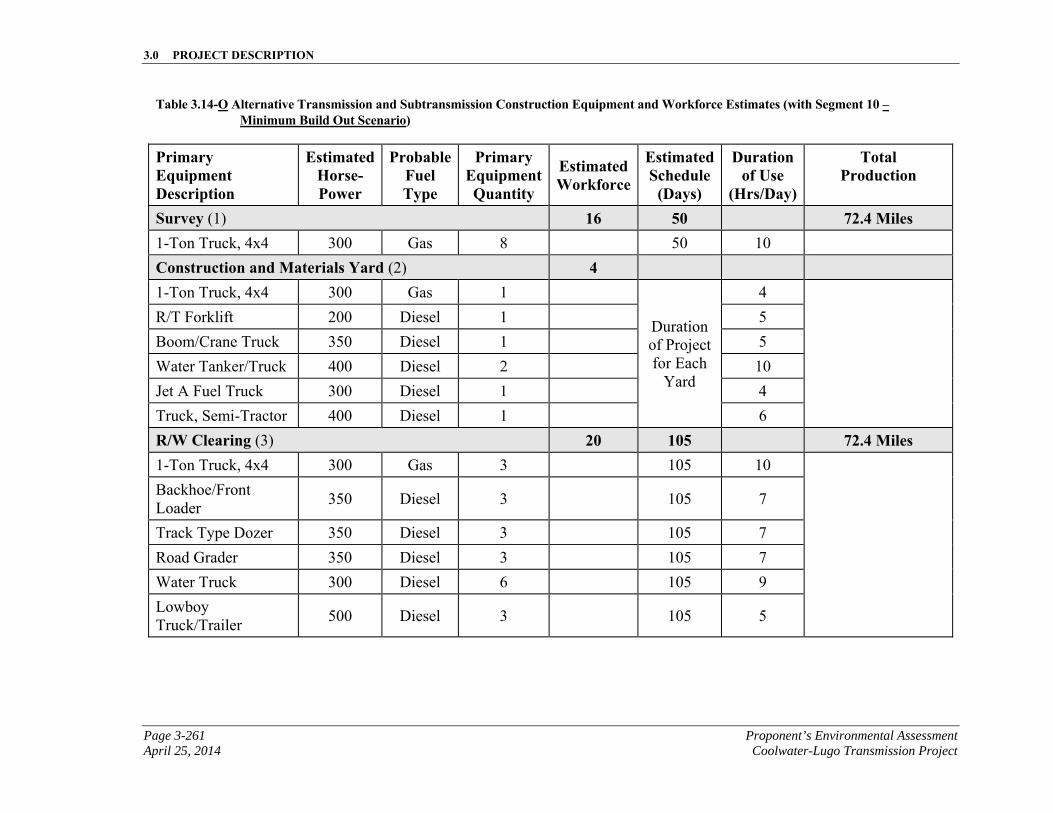
3.0 PROJECT DESCRIPTION
Page 3-261 Proponent’s Environmental Assessment April 25, 2014 Coolwater-Lugo Transmission Project
Table 3.14-O Alternative Transmission and Subtransmission Construction Equipment and Workforce Estimates (with Segment 10 – Minimum Build Out Scenario)
Primary Equipment Description
EstimatedHorse-Power
ProbableFuel Type
Primary EquipmentQuantity
Estimated Workforce
EstimatedSchedule
(Days)
Duration of Use
(Hrs/Day)
Total Production
Survey (1) 16 50 72.4 Miles 1-Ton Truck, 4x4 300 Gas 8 50 10
Construction and Materials Yard (2) 4 1-Ton Truck, 4x4 300 Gas 1
Duration of Project for Each
Yard
4
R/T Forklift 200 Diesel 1 5
Boom/Crane Truck 350 Diesel 1 5
Water Tanker/Truck 400 Diesel 2 10
Jet A Fuel Truck 300 Diesel 1 4
Truck, Semi-Tractor 400 Diesel 1 6
R/W Clearing (3) 20 105 72.4 Miles 1-Ton Truck, 4x4 300 Gas 3 105 10
Backhoe/Front Loader
350 Diesel 3 105 7
Track Type Dozer 350 Diesel 3 105 7
Road Grader 350 Diesel 3 105 7
Water Truck 300 Diesel 6 105 9
Lowboy Truck/Trailer
500 Diesel 3 105 5
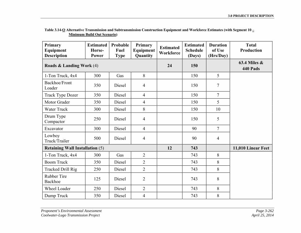
3.0 PROJECT DESCRIPTION
Proponent’s Environmental Assessment Page 3-262 Coolwater-Lugo Transmission Project April 25, 2014
Table 3.14-O Alternative Transmission and Subtransmission Construction Equipment and Workforce Estimates (with Segment 10 – Minimum Build Out Scenario)
Primary Equipment Description
EstimatedHorse-Power
ProbableFuel Type
Primary EquipmentQuantity
Estimated Workforce
EstimatedSchedule
(Days)
Duration of Use
(Hrs/Day)
Total Production
Roads & Landing Work (4) 24 150 63.4 Miles & 440 Pads
1-Ton Truck, 4x4 300 Gas 8 150 5
Backhoe/Front Loader
350 Diesel 4 150 7
Track Type Dozer 350 Diesel 4 150 7
Motor Grader 350 Diesel 4 150 5
Water Truck 300 Diesel 8 150 10
Drum Type Compactor
250 Diesel 4 150 5
Excavator 300 Diesel 4 90 7
Lowboy Truck/Trailer
500 Diesel 4 90 4
Retaining Wall Installation (5) 12 743 11,010 Linear Feet 1-Ton Truck, 4x4 300 Gas 2 743 8
Boom Truck 350 Diesel 2 743 8
Tracked Drill Rig 250 Diesel 2 743 8
Rubber Tire Backhoe
125 Diesel 2 743 8
Wheel Loader 250 Diesel 2 743 8
Dump Truck 350 Diesel 4 743 8
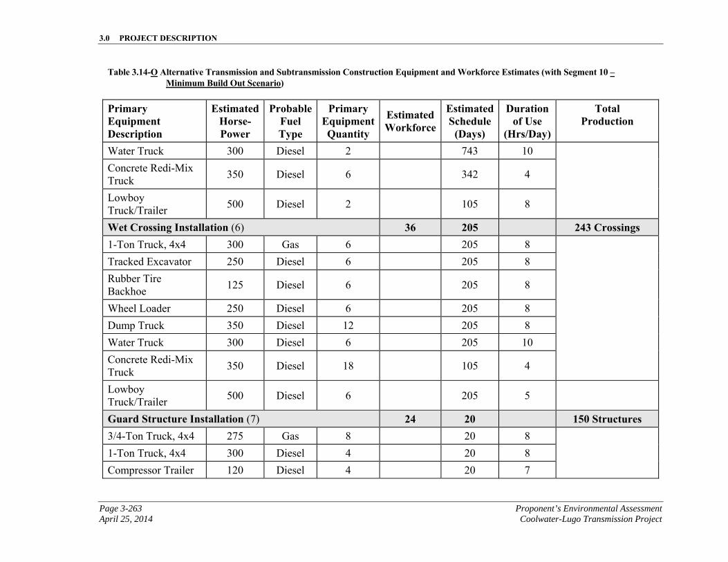
3.0 PROJECT DESCRIPTION
Page 3-263 Proponent’s Environmental Assessment April 25, 2014 Coolwater-Lugo Transmission Project
Table 3.14-O Alternative Transmission and Subtransmission Construction Equipment and Workforce Estimates (with Segment 10 – Minimum Build Out Scenario)
Primary Equipment Description
EstimatedHorse-Power
ProbableFuel Type
Primary EquipmentQuantity
Estimated Workforce
EstimatedSchedule
(Days)
Duration of Use
(Hrs/Day)
Total Production
Water Truck 300 Diesel 2 743 10
Concrete Redi-Mix Truck
350 Diesel 6 342 4
Lowboy Truck/Trailer
500 Diesel 2 105 8
Wet Crossing Installation (6) 36 205 243 Crossings 1-Ton Truck, 4x4 300 Gas 6 205 8
Tracked Excavator 250 Diesel 6 205 8
Rubber Tire Backhoe
125 Diesel 6 205 8
Wheel Loader 250 Diesel 6 205 8
Dump Truck 350 Diesel 12 205 8
Water Truck 300 Diesel 6 205 10
Concrete Redi-Mix Truck
350 Diesel 18 105 4
Lowboy Truck/Trailer
500 Diesel 6 205 5
Guard Structure Installation (7) 24 20 150 Structures 3/4-Ton Truck, 4x4 275 Gas 8 20 8
1-Ton Truck, 4x4 300 Diesel 4 20 8
Compressor Trailer 120 Diesel 4 20 7
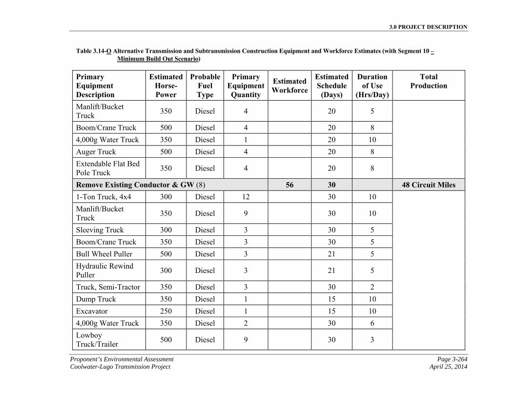
3.0 PROJECT DESCRIPTION
Proponent’s Environmental Assessment Page 3-264 Coolwater-Lugo Transmission Project April 25, 2014
Table 3.14-O Alternative Transmission and Subtransmission Construction Equipment and Workforce Estimates (with Segment 10 – Minimum Build Out Scenario)
Primary Equipment Description
EstimatedHorse-Power
ProbableFuel Type
Primary EquipmentQuantity
Estimated Workforce
EstimatedSchedule
(Days)
Duration of Use
(Hrs/Day)
Total Production
Manlift/Bucket Truck
350 Diesel 4 20 5
Boom/Crane Truck 500 Diesel 4 20 8
4,000g Water Truck 350 Diesel 1 20 10
Auger Truck 500 Diesel 4 20 8
Extendable Flat Bed Pole Truck
350 Diesel 4 20 8
Remove Existing Conductor & GW (8) 56 30 48 Circuit Miles 1-Ton Truck, 4x4 300 Diesel 12 30 10
Manlift/Bucket Truck
350 Diesel 9 30 10
Sleeving Truck 300 Diesel 3 30 5
Boom/Crane Truck 350 Diesel 3 30 5
Bull Wheel Puller 500 Diesel 3 21 5
Hydraulic Rewind Puller
300 Diesel 3 21 5
Truck, Semi-Tractor 350 Diesel 3 30 2
Dump Truck 350 Diesel 1 15 10
Excavator 250 Diesel 1 15 10
4,000g Water Truck 350 Diesel 2 30 6
Lowboy Truck/Trailer
500 Diesel 9 30 3
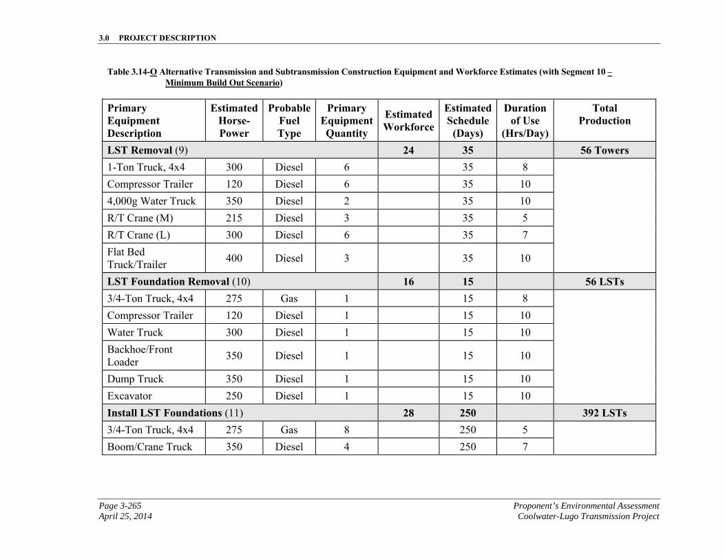
3.0 PROJECT DESCRIPTION
Page 3-265 Proponent’s Environmental Assessment April 25, 2014 Coolwater-Lugo Transmission Project
Table 3.14-O Alternative Transmission and Subtransmission Construction Equipment and Workforce Estimates (with Segment 10 – Minimum Build Out Scenario)
Primary Equipment Description
EstimatedHorse-Power
ProbableFuel Type
Primary EquipmentQuantity
Estimated Workforce
EstimatedSchedule
(Days)
Duration of Use
(Hrs/Day)
Total Production
LST Removal (9) 24 35 56 Towers 1-Ton Truck, 4x4 300 Diesel 6 35 8
Compressor Trailer 120 Diesel 6 35 10
4,000g Water Truck 350 Diesel 2 35 10
R/T Crane (M) 215 Diesel 3 35 5
R/T Crane (L) 300 Diesel 6 35 7
Flat Bed Truck/Trailer
400 Diesel 3 35 10
LST Foundation Removal (10) 16 15 56 LSTs 3/4-Ton Truck, 4x4 275 Gas 1 15 8
Compressor Trailer 120 Diesel 1 15 10
Water Truck 300 Diesel 1 15 10
Backhoe/Front Loader
350 Diesel 1 15 10
Dump Truck 350 Diesel 1 15 10
Excavator 250 Diesel 1 15 10
Install LST Foundations (11) 28 250 392 LSTs 3/4-Ton Truck, 4x4 275 Gas 8 250 5
Boom/Crane Truck 350 Diesel 4 250 7
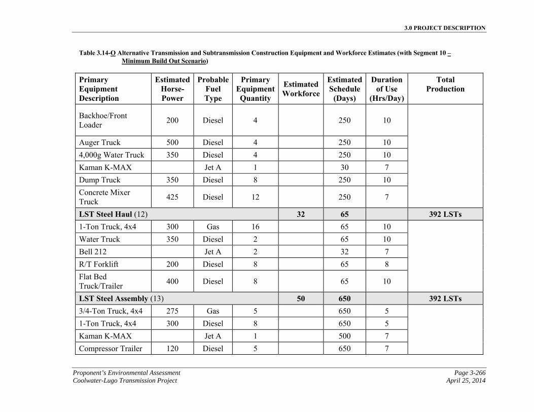
3.0 PROJECT DESCRIPTION
Proponent’s Environmental Assessment Page 3-266 Coolwater-Lugo Transmission Project April 25, 2014
Table 3.14-O Alternative Transmission and Subtransmission Construction Equipment and Workforce Estimates (with Segment 10 – Minimum Build Out Scenario)
Primary Equipment Description
EstimatedHorse-Power
ProbableFuel Type
Primary EquipmentQuantity
Estimated Workforce
EstimatedSchedule
(Days)
Duration of Use
(Hrs/Day)
Total Production
Backhoe/Front Loader
200 Diesel 4 250 10
Auger Truck 500 Diesel 4 250 10
4,000g Water Truck 350 Diesel 4 250 10
Kaman K-MAX Jet A 1 30 7
Dump Truck 350 Diesel 8 250 10
Concrete Mixer Truck
425 Diesel 12 250 7
LST Steel Haul (12) 32 65 392 LSTs 1-Ton Truck, 4x4 300 Gas 16 65 10
Water Truck 350 Diesel 2 65 10
Bell 212 Jet A 2 32 7
R/T Forklift 200 Diesel 8 65 8
Flat Bed Truck/Trailer
400 Diesel 8 65 10
LST Steel Assembly (13) 50 650 392 LSTs 3/4-Ton Truck, 4x4 275 Gas 5 650 5
1-Ton Truck, 4x4 300 Diesel 8 650 5
Kaman K-MAX Jet A 1 500 7
Compressor Trailer 120 Diesel 5 650 7
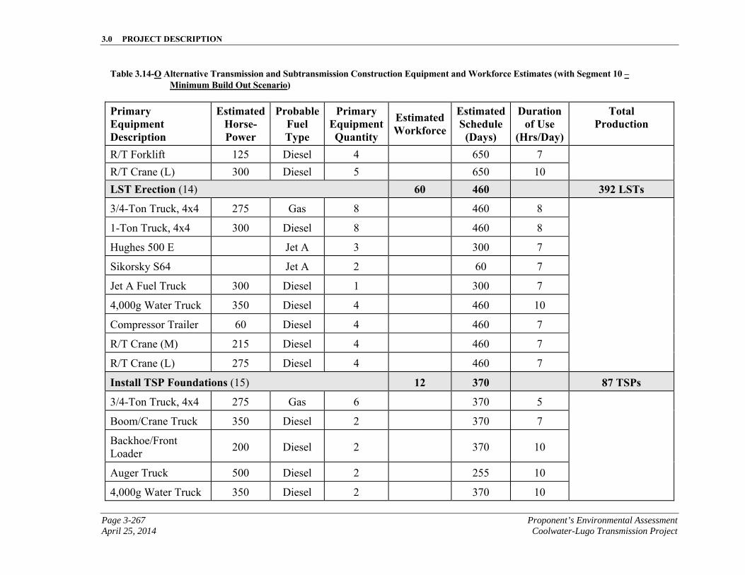
3.0 PROJECT DESCRIPTION
Page 3-267 Proponent’s Environmental Assessment April 25, 2014 Coolwater-Lugo Transmission Project
Table 3.14-O Alternative Transmission and Subtransmission Construction Equipment and Workforce Estimates (with Segment 10 – Minimum Build Out Scenario)
Primary Equipment Description
EstimatedHorse-Power
ProbableFuel Type
Primary EquipmentQuantity
Estimated Workforce
EstimatedSchedule
(Days)
Duration of Use
(Hrs/Day)
Total Production
R/T Forklift 125 Diesel 4 650 7
R/T Crane (L) 300 Diesel 5 650 10
LST Erection (14) 60 460 392 LSTs
3/4-Ton Truck, 4x4 275 Gas 8 460 8
1-Ton Truck, 4x4 300 Diesel 8 460 8
Hughes 500 E Jet A 3 300 7
Sikorsky S64 Jet A 2 60 7
Jet A Fuel Truck 300 Diesel 1 300 7
4,000g Water Truck 350 Diesel 4 460 10
Compressor Trailer 60 Diesel 4 460 7
R/T Crane (M) 215 Diesel 4 460 7
R/T Crane (L) 275 Diesel 4 460 7
Install TSP Foundations (15) 12 370 87 TSPs
3/4-Ton Truck, 4x4 275 Gas 6 370 5
Boom/Crane Truck 350 Diesel 2 370 7
Backhoe/Front Loader
200 Diesel 2 370 10
Auger Truck 500 Diesel 2 255 10
4,000g Water Truck 350 Diesel 2 370 10
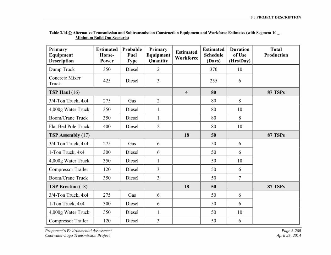
3.0 PROJECT DESCRIPTION
Proponent’s Environmental Assessment Page 3-268 Coolwater-Lugo Transmission Project April 25, 2014
Table 3.14-O Alternative Transmission and Subtransmission Construction Equipment and Workforce Estimates (with Segment 10 – Minimum Build Out Scenario)
Primary Equipment Description
EstimatedHorse-Power
ProbableFuel Type
Primary EquipmentQuantity
Estimated Workforce
EstimatedSchedule
(Days)
Duration of Use
(Hrs/Day)
Total Production
Dump Truck 350 Diesel 2 370 10
Concrete Mixer Truck
425 Diesel 3 255 6
TSP Haul (16) 4 80 87 TSPs
3/4-Ton Truck, 4x4 275 Gas 2 80 8
4,000g Water Truck 350 Diesel 1 80 10
Boom/Crane Truck 350 Diesel 1 80 8
Flat Bed Pole Truck 400 Diesel 2 80 10
TSP Assembly (17) 18 50 87 TSPs
3/4-Ton Truck, 4x4 275 Gas 6 50 6
1-Ton Truck, 4x4 300 Diesel 6 50 6
4,000g Water Truck 350 Diesel 1 50 10
Compressor Trailer 120 Diesel 3 50 6
Boom/Crane Truck 350 Diesel 3 50 7
TSP Erection (18) 18 50 87 TSPs
3/4-Ton Truck, 4x4 275 Gas 6 50 6
1-Ton Truck, 4x4 300 Diesel 6 50 6
4,000g Water Truck 350 Diesel 1 50 10
Compressor Trailer 120 Diesel 3 50 6
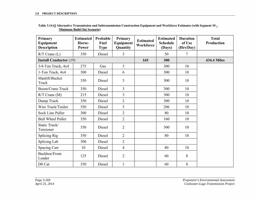
3.0 PROJECT DESCRIPTION
Page 3-269 Proponent’s Environmental Assessment April 25, 2014 Coolwater-Lugo Transmission Project
Table 3.14-O Alternative Transmission and Subtransmission Construction Equipment and Workforce Estimates (with Segment 10 – Minimum Build Out Scenario)
Primary Equipment Description
EstimatedHorse-Power
ProbableFuel Type
Primary EquipmentQuantity
Estimated Workforce
EstimatedSchedule
(Days)
Duration of Use
(Hrs/Day)
Total Production
R/T Crane (L) 350 Diesel 3 50 7
Install Conductor (19) 165 300 434.4 Miles 3/4-Ton Truck, 4x4 275 Gas 3 300 10
1-Ton Truck, 4x4 300 Diesel 6 300 10
Manlift/Bucket Truck
350 Diesel 3 300 10
Boom/Crane Truck 350 Diesel 3 300 10
R/T Crane (M) 215 Diesel 3 300 10
Dump Truck 350 Diesel 2 300 10
Wire Truck/Trailer 350 Diesel 3 206 10
Sock Line Puller 300 Diesel 2 80 10
Bull Wheel Puller 350 Diesel 2 160 10
Static Truck/ Tensioner
350 Diesel 2 300 10
Splicing Rig 350 Diesel 2 80 10
Splicing Lab 300 Diesel 2
Spacing Cart 10 Diesel 4 80 10
Backhoe/Front Loader
125 Diesel 2 60 8
D8 Cat 350 Diesel 1 60 8
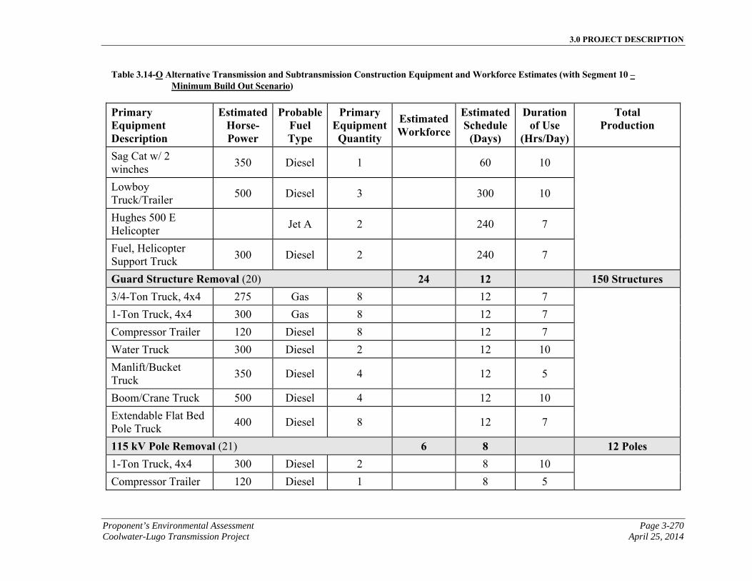
3.0 PROJECT DESCRIPTION
Proponent’s Environmental Assessment Page 3-270 Coolwater-Lugo Transmission Project April 25, 2014
Table 3.14-O Alternative Transmission and Subtransmission Construction Equipment and Workforce Estimates (with Segment 10 – Minimum Build Out Scenario)
Primary Equipment Description
EstimatedHorse-Power
ProbableFuel Type
Primary EquipmentQuantity
Estimated Workforce
EstimatedSchedule
(Days)
Duration of Use
(Hrs/Day)
Total Production
Sag Cat w/ 2 winches
350 Diesel 1 60 10
Lowboy Truck/Trailer
500 Diesel 3 300 10
Hughes 500 E Helicopter
Jet A 2 240 7
Fuel, Helicopter Support Truck
300 Diesel 2 240 7
Guard Structure Removal (20) 24 12 150 Structures 3/4-Ton Truck, 4x4 275 Gas 8 12 7
1-Ton Truck, 4x4 300 Gas 8 12 7
Compressor Trailer 120 Diesel 8 12 7
Water Truck 300 Diesel 2 12 10
Manlift/Bucket Truck
350 Diesel 4 12 5
Boom/Crane Truck 500 Diesel 4 12 10
Extendable Flat Bed Pole Truck
400 Diesel 8 12 7
115 kV Pole Removal (21) 6 8 12 Poles 1-Ton Truck, 4x4 300 Diesel 2 8 10
Compressor Trailer 120 Diesel 1 8 5
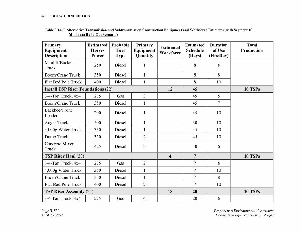
3.0 PROJECT DESCRIPTION
Page 3-271 Proponent’s Environmental Assessment April 25, 2014 Coolwater-Lugo Transmission Project
Table 3.14-O Alternative Transmission and Subtransmission Construction Equipment and Workforce Estimates (with Segment 10 – Minimum Build Out Scenario)
Primary Equipment Description
EstimatedHorse-Power
ProbableFuel Type
Primary EquipmentQuantity
Estimated Workforce
EstimatedSchedule
(Days)
Duration of Use
(Hrs/Day)
Total Production
Manlift/Bucket Truck
250 Diesel 1 8 8
Boom/Crane Truck 350 Diesel 1 8 8
Flat Bed Pole Truck 400 Diesel 1 8 10
Install TSP Riser Foundations (22) 12 45 10 TSPs 3/4-Ton Truck, 4x4 275 Gas 3 45 5
Boom/Crane Truck 350 Diesel 1 45 7
Backhoe/Front Loader
200 Diesel 1 45 10
Auger Truck 500 Diesel 1 30 10
4,000g Water Truck 350 Diesel 1 45 10
Dump Truck 350 Diesel 2 45 10
Concrete Mixer Truck
425 Diesel 3 30 6
TSP Riser Haul (23) 4 7 10 TSPs 3/4-Ton Truck, 4x4 275 Gas 2 7 8
4,000g Water Truck 350 Diesel 1 7 10
Boom/Crane Truck 350 Diesel 1 7 8
Flat Bed Pole Truck 400 Diesel 2 7 10
TSP Riser Assembly (24) 18 20 10 TSPs 3/4-Ton Truck, 4x4 275 Gas 6 20 6
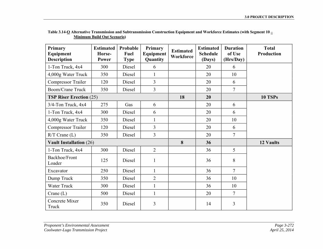
3.0 PROJECT DESCRIPTION
Proponent’s Environmental Assessment Page 3-272 Coolwater-Lugo Transmission Project April 25, 2014
Table 3.14-O Alternative Transmission and Subtransmission Construction Equipment and Workforce Estimates (with Segment 10 – Minimum Build Out Scenario)
Primary Equipment Description
EstimatedHorse-Power
ProbableFuel Type
Primary EquipmentQuantity
Estimated Workforce
EstimatedSchedule
(Days)
Duration of Use
(Hrs/Day)
Total Production
1-Ton Truck, 4x4 300 Diesel 6 20 6
4,000g Water Truck 350 Diesel 1 20 10
Compressor Trailer 120 Diesel 3 20 6
Boom/Crane Truck 350 Diesel 3 20 7
TSP Riser Erection (25) 18 20 10 TSPs 3/4-Ton Truck, 4x4 275 Gas 6 20 6
1-Ton Truck, 4x4 300 Diesel 6 20 6
4,000g Water Truck 350 Diesel 1 20 10
Compressor Trailer 120 Diesel 3 20 6
R/T Crane (L) 350 Diesel 3 20 7
Vault Installation (26) 8 36 12 Vaults 1-Ton Truck, 4x4 300 Diesel 2 36 5
Backhoe/Front Loader
125 Diesel 1 36 8
Excavator 250 Diesel 1 36 7
Dump Truck 350 Diesel 2 36 10
Water Truck 300 Diesel 1 36 10
Crane (L) 500 Diesel 1 20 7
Concrete Mixer Truck
350 Diesel 3 14 3
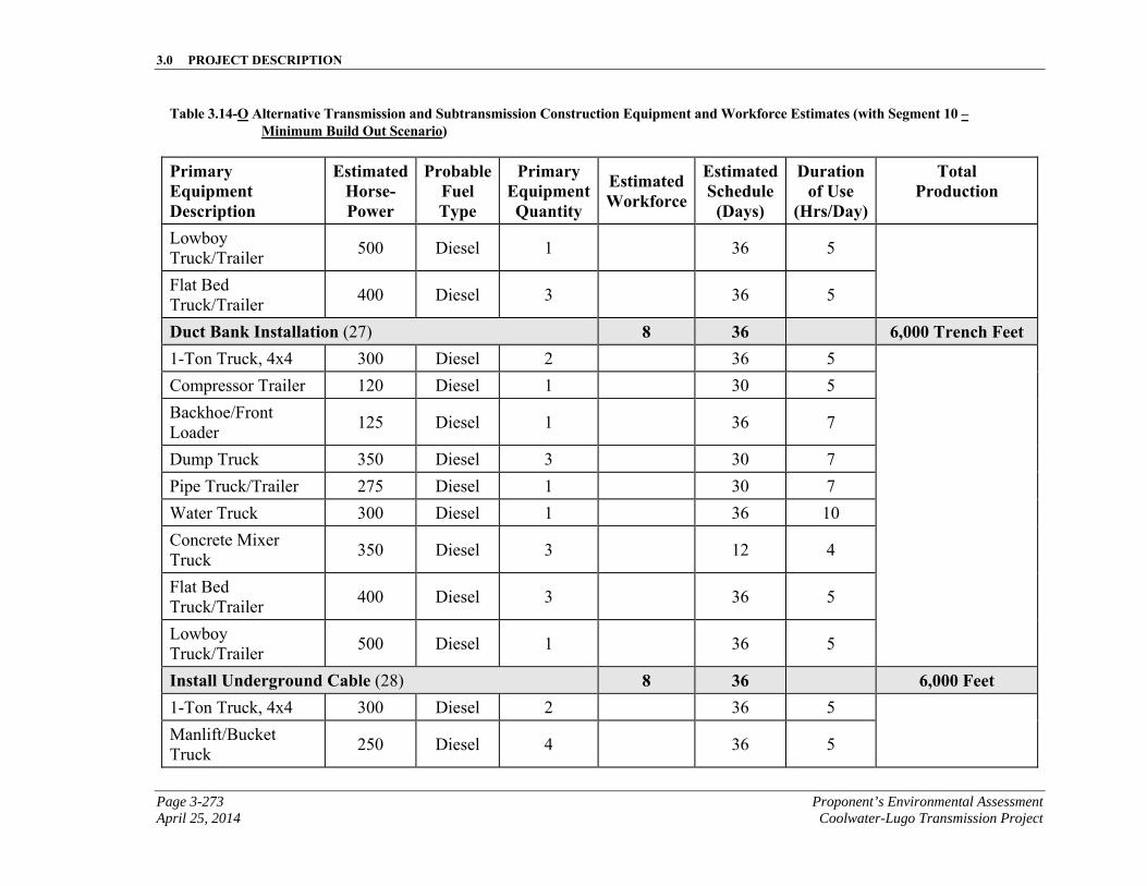
3.0 PROJECT DESCRIPTION
Page 3-273 Proponent’s Environmental Assessment April 25, 2014 Coolwater-Lugo Transmission Project
Table 3.14-O Alternative Transmission and Subtransmission Construction Equipment and Workforce Estimates (with Segment 10 – Minimum Build Out Scenario)
Primary Equipment Description
EstimatedHorse-Power
ProbableFuel Type
Primary EquipmentQuantity
Estimated Workforce
EstimatedSchedule
(Days)
Duration of Use
(Hrs/Day)
Total Production
Lowboy Truck/Trailer
500 Diesel 1 36 5
Flat Bed Truck/Trailer
400 Diesel 3 36 5
Duct Bank Installation (27) 8 36 6,000 Trench Feet 1-Ton Truck, 4x4 300 Diesel 2 36 5
Compressor Trailer 120 Diesel 1 30 5
Backhoe/Front Loader
125 Diesel 1 36 7
Dump Truck 350 Diesel 3 30 7
Pipe Truck/Trailer 275 Diesel 1 30 7
Water Truck 300 Diesel 1 36 10
Concrete Mixer Truck
350 Diesel 3 12 4
Flat Bed Truck/Trailer
400 Diesel 3 36 5
Lowboy Truck/Trailer
500 Diesel 1 36 5
Install Underground Cable (28) 8 36 6,000 Feet 1-Ton Truck, 4x4 300 Diesel 2 36 5
Manlift/Bucket
Truck 250 Diesel 4 36 5
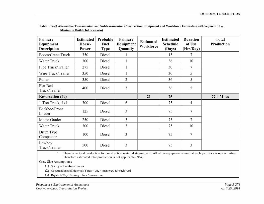
3.0 PROJECT DESCRIPTION
Proponent’s Environmental Assessment Page 3-274 Coolwater-Lugo Transmission Project April 25, 2014
Table 3.14-O Alternative Transmission and Subtransmission Construction Equipment and Workforce Estimates (with Segment 10 – Minimum Build Out Scenario)
Primary Equipment Description
EstimatedHorse-Power
ProbableFuel Type
Primary EquipmentQuantity
Estimated Workforce
EstimatedSchedule
(Days)
Duration of Use
(Hrs/Day)
Total Production
Boom/Crane Truck 350 Diesel 1 15 7
Water Truck 300 Diesel 1 36 10
Pipe Truck/Trailer 275 Diesel 1 30 7
Wire Truck/Trailer 350 Diesel 1 30 5
Puller 350 Diesel 2 36 5
Flat Bed Truck/Trailer
400 Diesel 3 36 5
Restoration (29) 21 75 72.4 Miles 1-Ton Truck, 4x4 300 Diesel 6 75 4
Backhoe/Front Loader
125 Diesel 3 75 7
Motor Grader 250 Diesel 3 75 7
Water Truck 300 Diesel 3 75 10
Drum Type Compactor
100 Diesel 3 75 7
Lowboy Truck/Trailer
500 Diesel 3 75 3
1. There is no total production for construction material staging yard. All of the equipment is used at each yard for various activities. Therefore estimated total production is not applicable (N/A).
Crew Size Assumptions: (1) Survey = four 4-man crews (2) Construction and Materials Yards = one 4-man crew for each yard (3) Right-of-Way Clearing = four 5-man crews
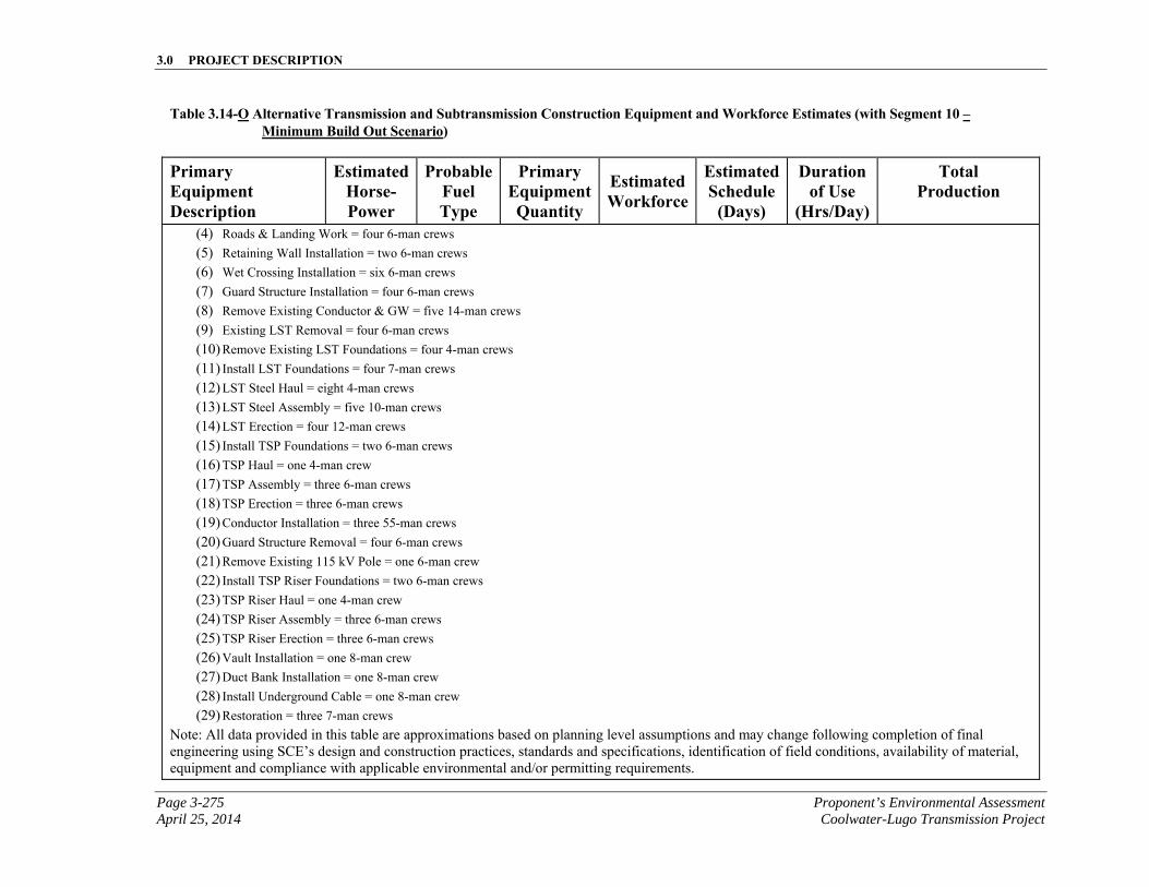
3.0 PROJECT DESCRIPTION
Page 3-275 Proponent’s Environmental Assessment April 25, 2014 Coolwater-Lugo Transmission Project
Table 3.14-O Alternative Transmission and Subtransmission Construction Equipment and Workforce Estimates (with Segment 10 – Minimum Build Out Scenario)
Primary Equipment Description
EstimatedHorse-Power
ProbableFuel Type
Primary EquipmentQuantity
Estimated Workforce
EstimatedSchedule
(Days)
Duration of Use
(Hrs/Day)
Total Production
(4) Roads & Landing Work = four 6-man crews (5) Retaining Wall Installation = two 6-man crews (6) Wet Crossing Installation = six 6-man crews (7) Guard Structure Installation = four 6-man crews (8) Remove Existing Conductor & GW = five 14-man crews (9) Existing LST Removal = four 6-man crews (10) Remove Existing LST Foundations = four 4-man crews (11) Install LST Foundations = four 7-man crews (12) LST Steel Haul = eight 4-man crews (13) LST Steel Assembly = five 10-man crews (14) LST Erection = four 12-man crews (15) Install TSP Foundations = two 6-man crews (16) TSP Haul = one 4-man crew (17) TSP Assembly = three 6-man crews (18) TSP Erection = three 6-man crews (19) Conductor Installation = three 55-man crews (20) Guard Structure Removal = four 6-man crews (21) Remove Existing 115 kV Pole = one 6-man crew (22) Install TSP Riser Foundations = two 6-man crews (23) TSP Riser Haul = one 4-man crew (24) TSP Riser Assembly = three 6-man crews (25) TSP Riser Erection = three 6-man crews (26) Vault Installation = one 8-man crew (27) Duct Bank Installation = one 8-man crew (28) Install Underground Cable = one 8-man crew (29) Restoration = three 7-man crews
Note: All data provided in this table are approximations based on planning level assumptions and may change following completion of final engineering using SCE’s design and construction practices, standards and specifications, identification of field conditions, availability of material, equipment and compliance with applicable environmental and/or permitting requirements.
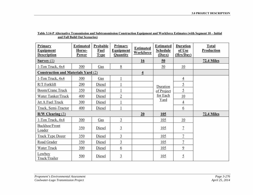
3.0 PROJECT DESCRIPTION
Proponent’s Environmental Assessment Page 3-276 Coolwater-Lugo Transmission Project April 25, 2014
Table 3.14-P Alternative Transmission and Subtransmission Construction Equipment and Workforce Estimates (with Segment 10 – Initial and Full Build Out Scenarios)
Primary Equipment Description
EstimatedHorse-Power
ProbableFuel Type
Primary EquipmentQuantity
Estimated Workforce
EstimatedSchedule
(Days)
Duration of Use
(Hrs/Day)
Total Production
Survey (1) 16 50 72.4 Miles 1-Ton Truck, 4x4 300 Gas 8 50 10
Construction and Materials Yard (2) 4 1-Ton Truck, 4x4 300 Gas 1
Duration of Project for Each
Yard
4
R/T Forklift 200 Diesel 1 5
Boom/Crane Truck 350 Diesel 1 5
Water Tanker/Truck 400 Diesel 2 10
Jet A Fuel Truck 300 Diesel 1 4
Truck, Semi-Tractor 400 Diesel 1 6
R/W Clearing (3) 20 105 72.4 Miles 1-Ton Truck, 4x4 300 Gas 3 105 10
Backhoe/Front Loader
350 Diesel 3 105 7
Track Type Dozer 350 Diesel 3 105 7
Road Grader 350 Diesel 3 105 7
Water Truck 300 Diesel 6 105 9
Lowboy Truck/Trailer
500 Diesel 3 105 5
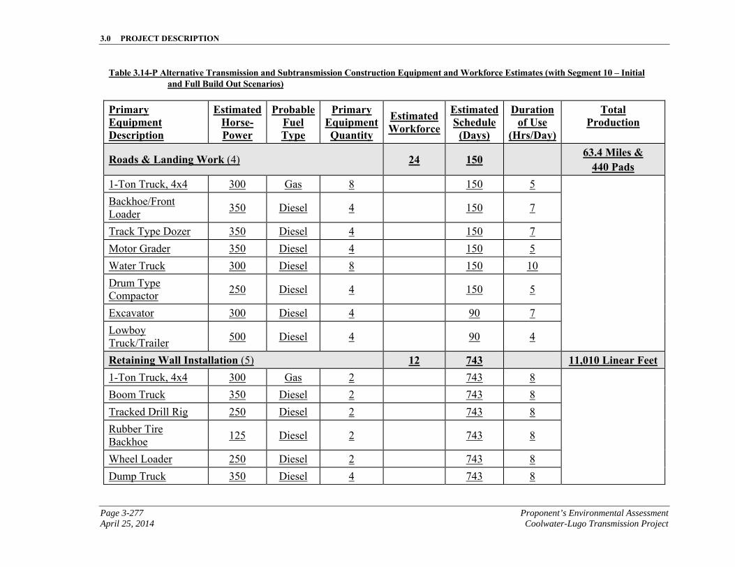
3.0 PROJECT DESCRIPTION
Page 3-277 Proponent’s Environmental Assessment April 25, 2014 Coolwater-Lugo Transmission Project
Table 3.14-P Alternative Transmission and Subtransmission Construction Equipment and Workforce Estimates (with Segment 10 – Initial and Full Build Out Scenarios)
Primary Equipment Description
EstimatedHorse-Power
ProbableFuel Type
Primary EquipmentQuantity
Estimated Workforce
EstimatedSchedule
(Days)
Duration of Use
(Hrs/Day)
Total Production
Roads & Landing Work (4) 24 150 63.4 Miles & 440 Pads
1-Ton Truck, 4x4 300 Gas 8 150 5
Backhoe/Front Loader
350 Diesel 4 150 7
Track Type Dozer 350 Diesel 4 150 7
Motor Grader 350 Diesel 4 150 5
Water Truck 300 Diesel 8 150 10
Drum Type Compactor
250 Diesel 4 150 5
Excavator 300 Diesel 4 90 7
Lowboy Truck/Trailer
500 Diesel 4 90 4
Retaining Wall Installation (5) 12 743 11,010 Linear Feet 1-Ton Truck, 4x4 300 Gas 2 743 8
Boom Truck 350 Diesel 2 743 8
Tracked Drill Rig 250 Diesel 2 743 8
Rubber Tire Backhoe
125 Diesel 2 743 8
Wheel Loader 250 Diesel 2 743 8
Dump Truck 350 Diesel 4 743 8
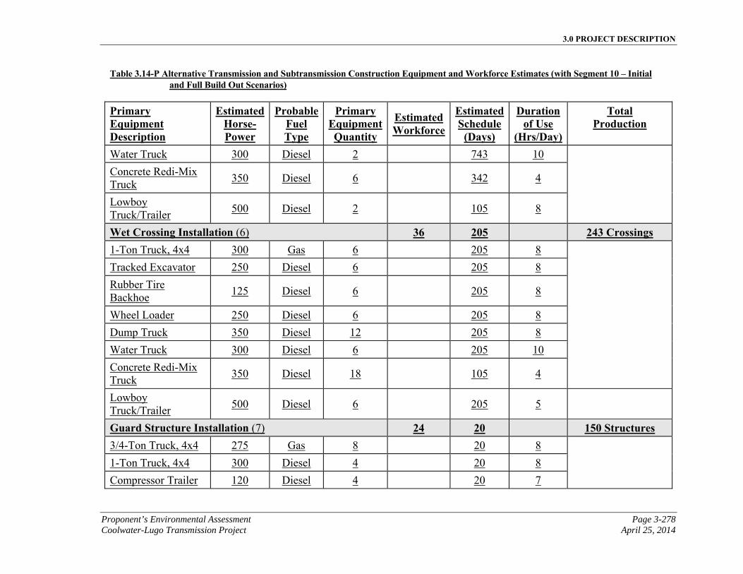
3.0 PROJECT DESCRIPTION
Proponent’s Environmental Assessment Page 3-278 Coolwater-Lugo Transmission Project April 25, 2014
Table 3.14-P Alternative Transmission and Subtransmission Construction Equipment and Workforce Estimates (with Segment 10 – Initial and Full Build Out Scenarios)
Primary Equipment Description
EstimatedHorse-Power
ProbableFuel Type
Primary EquipmentQuantity
Estimated Workforce
EstimatedSchedule
(Days)
Duration of Use
(Hrs/Day)
Total Production
Water Truck 300 Diesel 2 743 10
Concrete Redi-Mix Truck
350 Diesel 6 342 4
Lowboy Truck/Trailer
500 Diesel 2 105 8
Wet Crossing Installation (6) 36 205 243 Crossings 1-Ton Truck, 4x4 300 Gas 6 205 8
Tracked Excavator 250 Diesel 6 205 8
Rubber Tire Backhoe
125 Diesel 6 205 8
Wheel Loader 250 Diesel 6 205 8
Dump Truck 350 Diesel 12 205 8
Water Truck 300 Diesel 6 205 10
Concrete Redi-Mix Truck
350 Diesel 18 105 4
Lowboy Truck/Trailer
500 Diesel 6 205 5
Guard Structure Installation (7) 24 20 150 Structures 3/4-Ton Truck, 4x4 275 Gas 8 20 8
1-Ton Truck, 4x4 300 Diesel 4 20 8
Compressor Trailer 120 Diesel 4 20 7
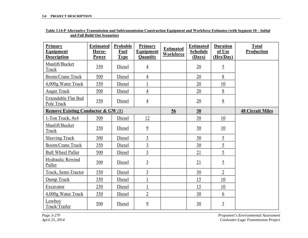
3.0 PROJECT DESCRIPTION
Page 3-279 Proponent’s Environmental Assessment April 25, 2014 Coolwater-Lugo Transmission Project
Table 3.14-P Alternative Transmission and Subtransmission Construction Equipment and Workforce Estimates (with Segment 10 – Initial and Full Build Out Scenarios)
Primary Equipment Description
EstimatedHorse-Power
ProbableFuel Type
Primary EquipmentQuantity
Estimated Workforce
EstimatedSchedule
(Days)
Duration of Use
(Hrs/Day)
Total Production
Manlift/Bucket Truck
350 Diesel 4 20 5
Boom/Crane Truck 500 Diesel 4 20 8
4,000g Water Truck 350 Diesel 1 20 10
Auger Truck 500 Diesel 4 20 8
Extendable Flat Bed Pole Truck
350 Diesel 4 20 8
Remove Existing Conductor & GW (8) 56 30 48 Circuit Miles 1-Ton Truck, 4x4 300 Diesel 12 30 10
Manlift/Bucket Truck
350 Diesel 9 30 10
Sleeving Truck 300 Diesel 3 30 5
Boom/Crane Truck 350 Diesel 3 30 5
Bull Wheel Puller 500 Diesel 3 21 5
Hydraulic Rewind Puller
300 Diesel 3 21 5
Truck, Semi-Tractor 350 Diesel 3 30 2
Dump Truck 350 Diesel 1 15 10
Excavator 250 Diesel 1 15 10
4,000g Water Truck 350 Diesel 2 30 6
Lowboy Truck/Trailer
500 Diesel 9 30 3
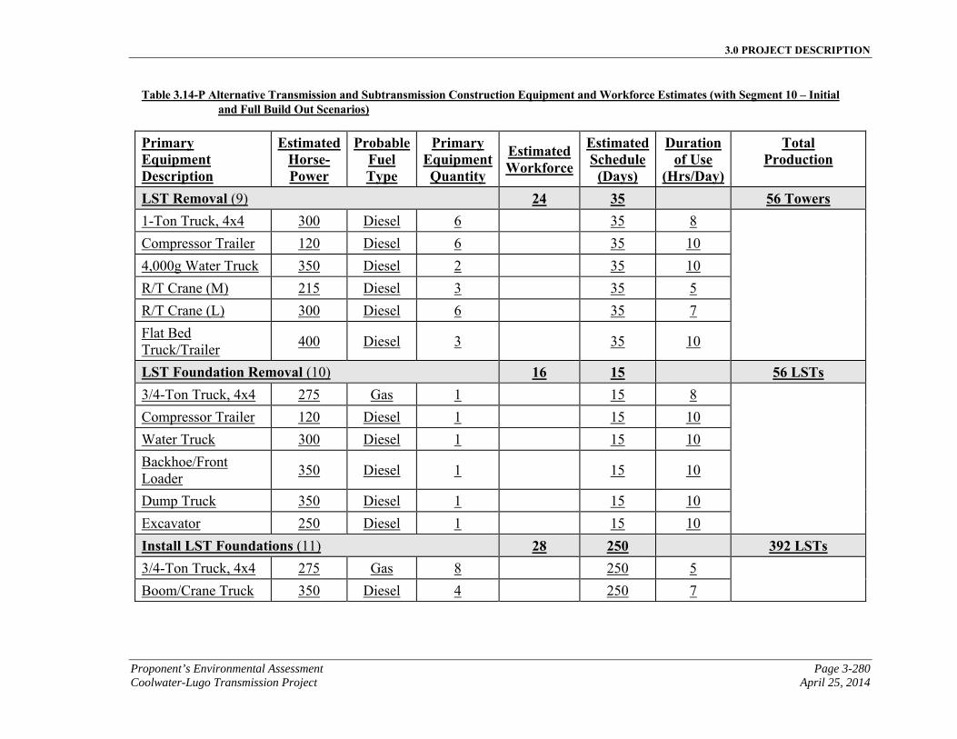
3.0 PROJECT DESCRIPTION
Proponent’s Environmental Assessment Page 3-280 Coolwater-Lugo Transmission Project April 25, 2014
Table 3.14-P Alternative Transmission and Subtransmission Construction Equipment and Workforce Estimates (with Segment 10 – Initial and Full Build Out Scenarios)
Primary Equipment Description
EstimatedHorse-Power
ProbableFuel Type
Primary EquipmentQuantity
Estimated Workforce
EstimatedSchedule
(Days)
Duration of Use
(Hrs/Day)
Total Production
LST Removal (9) 24 35 56 Towers 1-Ton Truck, 4x4 300 Diesel 6 35 8
Compressor Trailer 120 Diesel 6 35 10
4,000g Water Truck 350 Diesel 2 35 10
R/T Crane (M) 215 Diesel 3 35 5
R/T Crane (L) 300 Diesel 6 35 7
Flat Bed Truck/Trailer
400 Diesel 3 35 10
LST Foundation Removal (10) 16 15 56 LSTs 3/4-Ton Truck, 4x4 275 Gas 1 15 8
Compressor Trailer 120 Diesel 1 15 10
Water Truck 300 Diesel 1 15 10
Backhoe/Front Loader
350 Diesel 1 15 10
Dump Truck 350 Diesel 1 15 10
Excavator 250 Diesel 1 15 10
Install LST Foundations (11) 28 250 392 LSTs 3/4-Ton Truck, 4x4 275 Gas 8 250 5
Boom/Crane Truck 350 Diesel 4 250 7
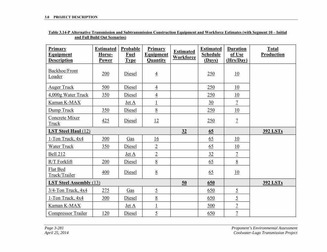
3.0 PROJECT DESCRIPTION
Page 3-281 Proponent’s Environmental Assessment April 25, 2014 Coolwater-Lugo Transmission Project
Table 3.14-P Alternative Transmission and Subtransmission Construction Equipment and Workforce Estimates (with Segment 10 – Initial and Full Build Out Scenarios)
Primary Equipment Description
EstimatedHorse-Power
ProbableFuel Type
Primary EquipmentQuantity
Estimated Workforce
EstimatedSchedule
(Days)
Duration of Use
(Hrs/Day)
Total Production
Backhoe/Front Loader
200 Diesel 4 250 10
Auger Truck 500 Diesel 4 250 10
4,000g Water Truck 350 Diesel 4 250 10
Kaman K-MAX Jet A 1 30 7
Dump Truck 350 Diesel 8 250 10
Concrete Mixer Truck
425 Diesel 12 250 7
LST Steel Haul (12) 32 65 392 LSTs 1-Ton Truck, 4x4 300 Gas 16 65 10
Water Truck 350 Diesel 2 65 10
Bell 212 Jet A 2 32 7
R/T Forklift 200 Diesel 8 65 8
Flat Bed Truck/Trailer
400 Diesel 8 65 10
LST Steel Assembly (13) 50 650 392 LSTs 3/4-Ton Truck, 4x4 275 Gas 5 650 5
1-Ton Truck, 4x4 300 Diesel 8 650 5
Kaman K-MAX Jet A 1 500 7
Compressor Trailer 120 Diesel 5 650 7
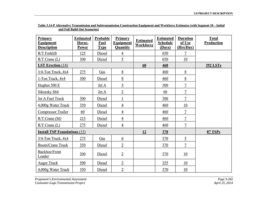
3.0 PROJECT DESCRIPTION
Proponent’s Environmental Assessment Page 3-282 Coolwater-Lugo Transmission Project April 25, 2014
Table 3.14-P Alternative Transmission and Subtransmission Construction Equipment and Workforce Estimates (with Segment 10 – Initial and Full Build Out Scenarios)
Primary Equipment Description
EstimatedHorse-Power
ProbableFuel Type
Primary EquipmentQuantity
Estimated Workforce
EstimatedSchedule
(Days)
Duration of Use
(Hrs/Day)
Total Production
R/T Forklift 125 Diesel 4 650 7
R/T Crane (L) 300 Diesel 5 650 10
LST Erection (14) 60 460 392 LSTs
3/4-Ton Truck, 4x4 275 Gas 8 460 8
1-Ton Truck, 4x4 300 Diesel 8 460 8
Hughes 500 E Jet A 3 300 7
Sikorsky S64 Jet A 2 60 7
Jet A Fuel Truck 300 Diesel 1 300 7
4,000g Water Truck 350 Diesel 4 460 10
Compressor Trailer 60 Diesel 4 460 7
R/T Crane (M) 215 Diesel 4 460 7
R/T Crane (L) 275 Diesel 4 460 7
Install TSP Foundations (15) 12 370 87 TSPs
3/4-Ton Truck, 4x4 275 Gas 6 370 5
Boom/Crane Truck 350 Diesel 2 370 7
Backhoe/Front Loader
200 Diesel 2 370 10
Auger Truck 500 Diesel 2 255 10
4,000g Water Truck 350 Diesel 2 370 10
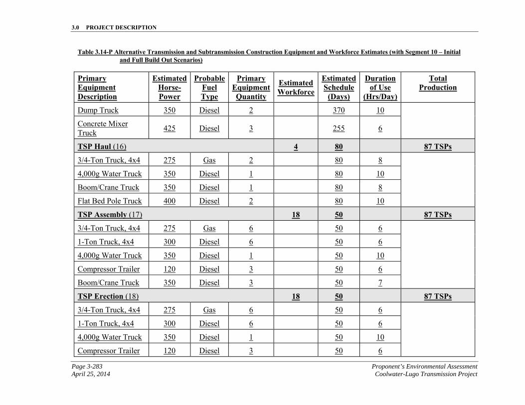
3.0 PROJECT DESCRIPTION
Page 3-283 Proponent’s Environmental Assessment April 25, 2014 Coolwater-Lugo Transmission Project
Table 3.14-P Alternative Transmission and Subtransmission Construction Equipment and Workforce Estimates (with Segment 10 – Initial and Full Build Out Scenarios)
Primary Equipment Description
EstimatedHorse-Power
ProbableFuel Type
Primary EquipmentQuantity
Estimated Workforce
EstimatedSchedule
(Days)
Duration of Use
(Hrs/Day)
Total Production
Dump Truck 350 Diesel 2 370 10
Concrete Mixer Truck
425 Diesel 3 255 6
TSP Haul (16) 4 80 87 TSPs
3/4-Ton Truck, 4x4 275 Gas 2 80 8
4,000g Water Truck 350 Diesel 1 80 10
Boom/Crane Truck 350 Diesel 1 80 8
Flat Bed Pole Truck 400 Diesel 2 80 10
TSP Assembly (17) 18 50 87 TSPs
3/4-Ton Truck, 4x4 275 Gas 6 50 6
1-Ton Truck, 4x4 300 Diesel 6 50 6
4,000g Water Truck 350 Diesel 1 50 10
Compressor Trailer 120 Diesel 3 50 6
Boom/Crane Truck 350 Diesel 3 50 7
TSP Erection (18) 18 50 87 TSPs
3/4-Ton Truck, 4x4 275 Gas 6 50 6
1-Ton Truck, 4x4 300 Diesel 6 50 6
4,000g Water Truck 350 Diesel 1 50 10
Compressor Trailer 120 Diesel 3 50 6
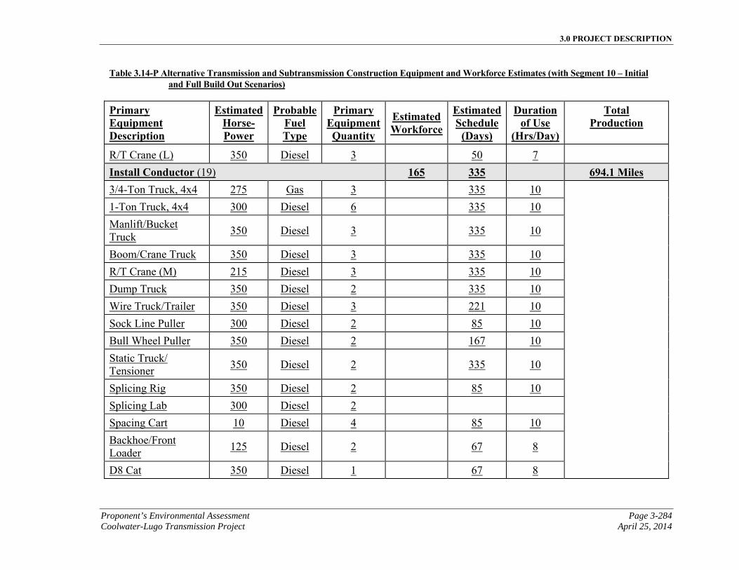
3.0 PROJECT DESCRIPTION
Proponent’s Environmental Assessment Page 3-284 Coolwater-Lugo Transmission Project April 25, 2014
Table 3.14-P Alternative Transmission and Subtransmission Construction Equipment and Workforce Estimates (with Segment 10 – Initial and Full Build Out Scenarios)
Primary Equipment Description
EstimatedHorse-Power
ProbableFuel Type
Primary EquipmentQuantity
Estimated Workforce
EstimatedSchedule
(Days)
Duration of Use
(Hrs/Day)
Total Production
R/T Crane (L) 350 Diesel 3 50 7
Install Conductor (19) 165 335 694.1 Miles 3/4-Ton Truck, 4x4 275 Gas 3 335 10
1-Ton Truck, 4x4 300 Diesel 6 335 10
Manlift/Bucket Truck
350 Diesel 3 335 10
Boom/Crane Truck 350 Diesel 3 335 10
R/T Crane (M) 215 Diesel 3 335 10
Dump Truck 350 Diesel 2 335 10
Wire Truck/Trailer 350 Diesel 3 221 10
Sock Line Puller 300 Diesel 2 85 10
Bull Wheel Puller 350 Diesel 2 167 10
Static Truck/ Tensioner
350 Diesel 2 335 10
Splicing Rig 350 Diesel 2 85 10
Splicing Lab 300 Diesel 2
Spacing Cart 10 Diesel 4 85 10
Backhoe/Front Loader
125 Diesel 2 67 8
D8 Cat 350 Diesel 1 67 8
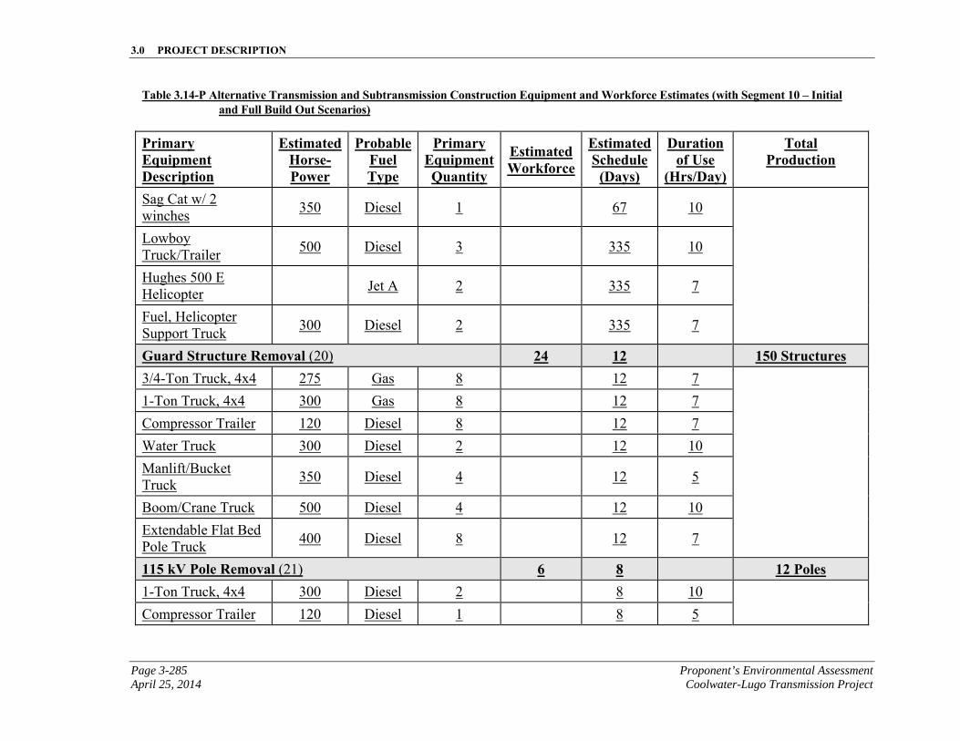
3.0 PROJECT DESCRIPTION
Page 3-285 Proponent’s Environmental Assessment April 25, 2014 Coolwater-Lugo Transmission Project
Table 3.14-P Alternative Transmission and Subtransmission Construction Equipment and Workforce Estimates (with Segment 10 – Initial and Full Build Out Scenarios)
Primary Equipment Description
EstimatedHorse-Power
ProbableFuel Type
Primary EquipmentQuantity
Estimated Workforce
EstimatedSchedule
(Days)
Duration of Use
(Hrs/Day)
Total Production
Sag Cat w/ 2 winches
350 Diesel 1 67 10
Lowboy Truck/Trailer
500 Diesel 3 335 10
Hughes 500 E Helicopter
Jet A 2 335 7
Fuel, Helicopter Support Truck
300 Diesel 2 335 7
Guard Structure Removal (20) 24 12 150 Structures 3/4-Ton Truck, 4x4 275 Gas 8 12 7
1-Ton Truck, 4x4 300 Gas 8 12 7
Compressor Trailer 120 Diesel 8 12 7
Water Truck 300 Diesel 2 12 10
Manlift/Bucket Truck
350 Diesel 4 12 5
Boom/Crane Truck 500 Diesel 4 12 10
Extendable Flat Bed Pole Truck
400 Diesel 8 12 7
115 kV Pole Removal (21) 6 8 12 Poles 1-Ton Truck, 4x4 300 Diesel 2 8 10
Compressor Trailer 120 Diesel 1 8 5
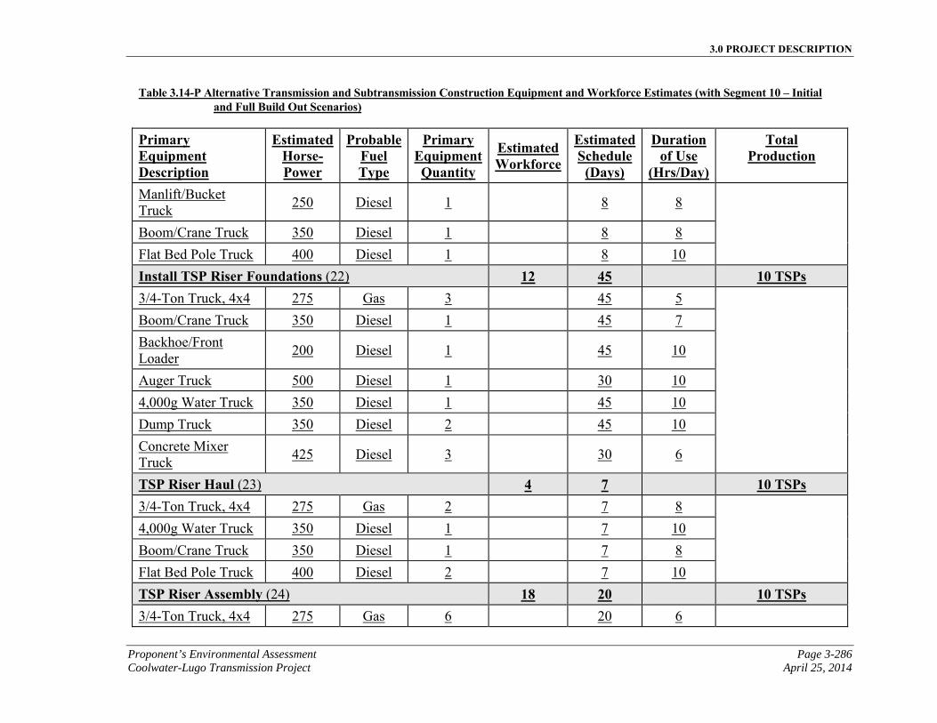
3.0 PROJECT DESCRIPTION
Proponent’s Environmental Assessment Page 3-286 Coolwater-Lugo Transmission Project April 25, 2014
Table 3.14-P Alternative Transmission and Subtransmission Construction Equipment and Workforce Estimates (with Segment 10 – Initial and Full Build Out Scenarios)
Primary Equipment Description
EstimatedHorse-Power
ProbableFuel Type
Primary EquipmentQuantity
Estimated Workforce
EstimatedSchedule
(Days)
Duration of Use
(Hrs/Day)
Total Production
Manlift/Bucket Truck
250 Diesel 1 8 8
Boom/Crane Truck 350 Diesel 1 8 8
Flat Bed Pole Truck 400 Diesel 1 8 10
Install TSP Riser Foundations (22) 12 45 10 TSPs 3/4-Ton Truck, 4x4 275 Gas 3 45 5
Boom/Crane Truck 350 Diesel 1 45 7
Backhoe/Front Loader
200 Diesel 1 45 10
Auger Truck 500 Diesel 1 30 10
4,000g Water Truck 350 Diesel 1 45 10
Dump Truck 350 Diesel 2 45 10
Concrete Mixer Truck
425 Diesel 3 30 6
TSP Riser Haul (23) 4 7 10 TSPs 3/4-Ton Truck, 4x4 275 Gas 2 7 8
4,000g Water Truck 350 Diesel 1 7 10
Boom/Crane Truck 350 Diesel 1 7 8
Flat Bed Pole Truck 400 Diesel 2 7 10
TSP Riser Assembly (24) 18 20 10 TSPs 3/4-Ton Truck, 4x4 275 Gas 6 20 6
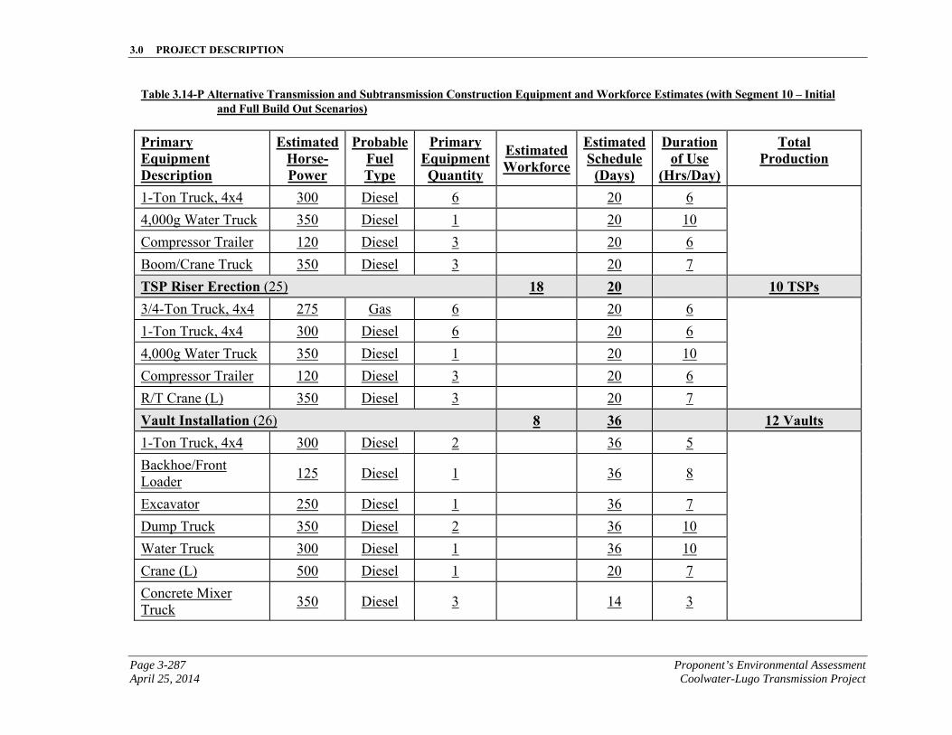
3.0 PROJECT DESCRIPTION
Page 3-287 Proponent’s Environmental Assessment April 25, 2014 Coolwater-Lugo Transmission Project
Table 3.14-P Alternative Transmission and Subtransmission Construction Equipment and Workforce Estimates (with Segment 10 – Initial and Full Build Out Scenarios)
Primary Equipment Description
EstimatedHorse-Power
ProbableFuel Type
Primary EquipmentQuantity
Estimated Workforce
EstimatedSchedule
(Days)
Duration of Use
(Hrs/Day)
Total Production
1-Ton Truck, 4x4 300 Diesel 6 20 6
4,000g Water Truck 350 Diesel 1 20 10
Compressor Trailer 120 Diesel 3 20 6
Boom/Crane Truck 350 Diesel 3 20 7
TSP Riser Erection (25) 18 20 10 TSPs 3/4-Ton Truck, 4x4 275 Gas 6 20 6
1-Ton Truck, 4x4 300 Diesel 6 20 6
4,000g Water Truck 350 Diesel 1 20 10
Compressor Trailer 120 Diesel 3 20 6
R/T Crane (L) 350 Diesel 3 20 7
Vault Installation (26) 8 36 12 Vaults 1-Ton Truck, 4x4 300 Diesel 2 36 5
Backhoe/Front Loader
125 Diesel 1 36 8
Excavator 250 Diesel 1 36 7
Dump Truck 350 Diesel 2 36 10
Water Truck 300 Diesel 1 36 10
Crane (L) 500 Diesel 1 20 7
Concrete Mixer Truck
350 Diesel 3 14 3
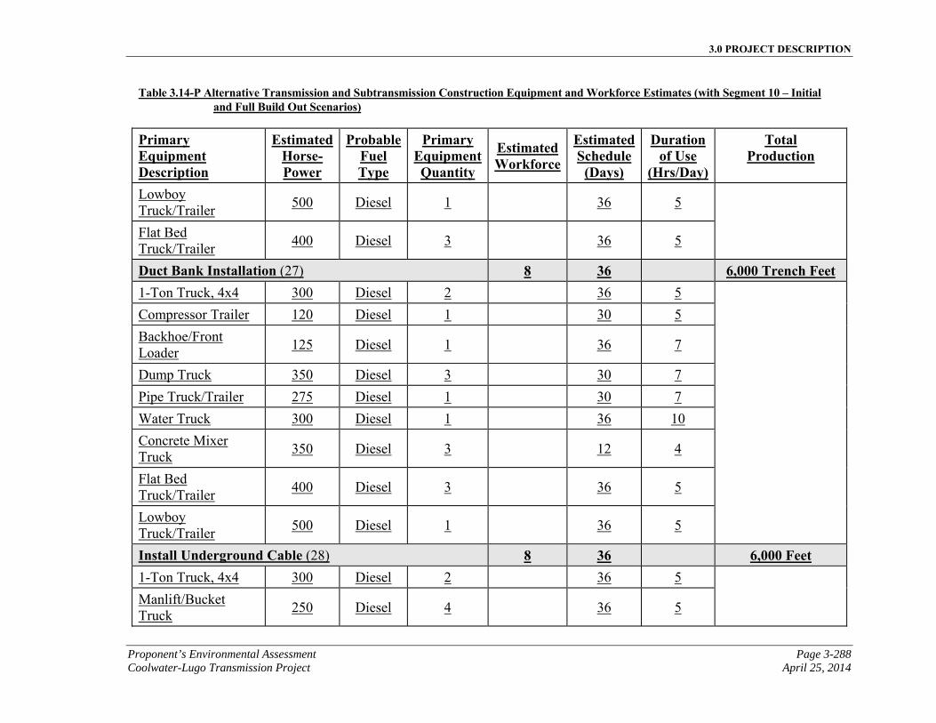
3.0 PROJECT DESCRIPTION
Proponent’s Environmental Assessment Page 3-288 Coolwater-Lugo Transmission Project April 25, 2014
Table 3.14-P Alternative Transmission and Subtransmission Construction Equipment and Workforce Estimates (with Segment 10 – Initial and Full Build Out Scenarios)
Primary Equipment Description
EstimatedHorse-Power
ProbableFuel Type
Primary EquipmentQuantity
Estimated Workforce
EstimatedSchedule
(Days)
Duration of Use
(Hrs/Day)
Total Production
Lowboy Truck/Trailer
500 Diesel 1 36 5
Flat Bed Truck/Trailer
400 Diesel 3 36 5
Duct Bank Installation (27) 8 36 6,000 Trench Feet 1-Ton Truck, 4x4 300 Diesel 2 36 5
Compressor Trailer 120 Diesel 1 30 5
Backhoe/Front Loader
125 Diesel 1 36 7
Dump Truck 350 Diesel 3 30 7
Pipe Truck/Trailer 275 Diesel 1 30 7
Water Truck 300 Diesel 1 36 10
Concrete Mixer Truck
350 Diesel 3 12 4
Flat Bed Truck/Trailer
400 Diesel 3 36 5
Lowboy Truck/Trailer
500 Diesel 1 36 5
Install Underground Cable (28) 8 36 6,000 Feet 1-Ton Truck, 4x4 300 Diesel 2 36 5
Manlift/Bucket
Truck 250 Diesel 4 36 5
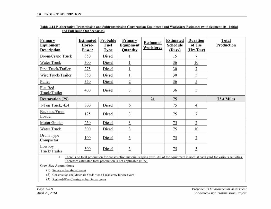
3.0 PROJECT DESCRIPTION
Page 3-289 Proponent’s Environmental Assessment April 25, 2014 Coolwater-Lugo Transmission Project
Table 3.14-P Alternative Transmission and Subtransmission Construction Equipment and Workforce Estimates (with Segment 10 – Initial and Full Build Out Scenarios)
Primary Equipment Description
EstimatedHorse-Power
ProbableFuel Type
Primary EquipmentQuantity
Estimated Workforce
EstimatedSchedule
(Days)
Duration of Use
(Hrs/Day)
Total Production
Boom/Crane Truck 350 Diesel 1 15 7
Water Truck 300 Diesel 1 36 10
Pipe Truck/Trailer 275 Diesel 1 30 7
Wire Truck/Trailer 350 Diesel 1 30 5
Puller 350 Diesel 2 36 5
Flat Bed Truck/Trailer
400 Diesel 3 36 5
Restoration (29) 21 75 72.4 Miles 1-Ton Truck, 4x4 300 Diesel 6 75 4
Backhoe/Front Loader
125 Diesel 3 75 7
Motor Grader 250 Diesel 3 75 7
Water Truck 300 Diesel 3 75 10
Drum Type Compactor
100 Diesel 3 75 7
Lowboy Truck/Trailer
500 Diesel 3 75 3
1. There is no total production for construction material staging yard. All of the equipment is used at each yard for various activities. Therefore estimated total production is not applicable (N/A).
Crew Size Assumptions: (1) Survey = four 4-man crews (2) Construction and Materials Yards = one 4-man crew for each yard (3) Right-of-Way Clearing = four 5-man crews
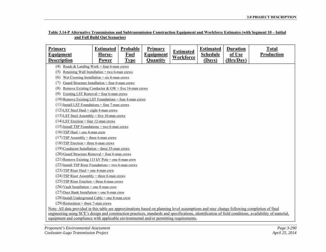
3.0 PROJECT DESCRIPTION
Proponent’s Environmental Assessment Page 3-290 Coolwater-Lugo Transmission Project April 25, 2014
Table 3.14-P Alternative Transmission and Subtransmission Construction Equipment and Workforce Estimates (with Segment 10 – Initial and Full Build Out Scenarios)
Primary Equipment Description
EstimatedHorse-Power
ProbableFuel Type
Primary EquipmentQuantity
Estimated Workforce
EstimatedSchedule
(Days)
Duration of Use
(Hrs/Day)
Total Production
(4) Roads & Landing Work = four 6-man crews (5) Retaining Wall Installation = two 6-man crews (6) Wet Crossing Installation = six 6-man crews (7) Guard Structure Installation = four 6-man crews (8) Remove Existing Conductor & GW = five 14-man crews (9) Existing LST Removal = four 6-man crews (10) Remove Existing LST Foundations = four 4-man crews (11) Install LST Foundations = four 7-man crews (12) LST Steel Haul = eight 4-man crews (13) LST Steel Assembly = five 10-man crews (14) LST Erection = four 12-man crews (15) Install TSP Foundations = two 6-man crews (16) TSP Haul = one 4-man crew (17) TSP Assembly = three 6-man crews (18) TSP Erection = three 6-man crews (19) Conductor Installation = three 55-man crews (20) Guard Structure Removal = four 6-man crews (21) Remove Existing 115 kV Pole = one 6-man crew (22) Install TSP Riser Foundations = two 6-man crews (23) TSP Riser Haul = one 4-man crew (24) TSP Riser Assembly = three 6-man crews (25) TSP Riser Erection = three 6-man crews (26) Vault Installation = one 8-man crew (27) Duct Bank Installation = one 8-man crew (28) Install Underground Cable = one 8-man crew (29) Restoration = three 7-man crews
Note: All data provided in this table are approximations based on planning level assumptions and may change following completion of final engineering using SCE’s design and construction practices, standards and specifications, identification of field conditions, availability of material, equipment and compliance with applicable environmental and/or permitting requirements.
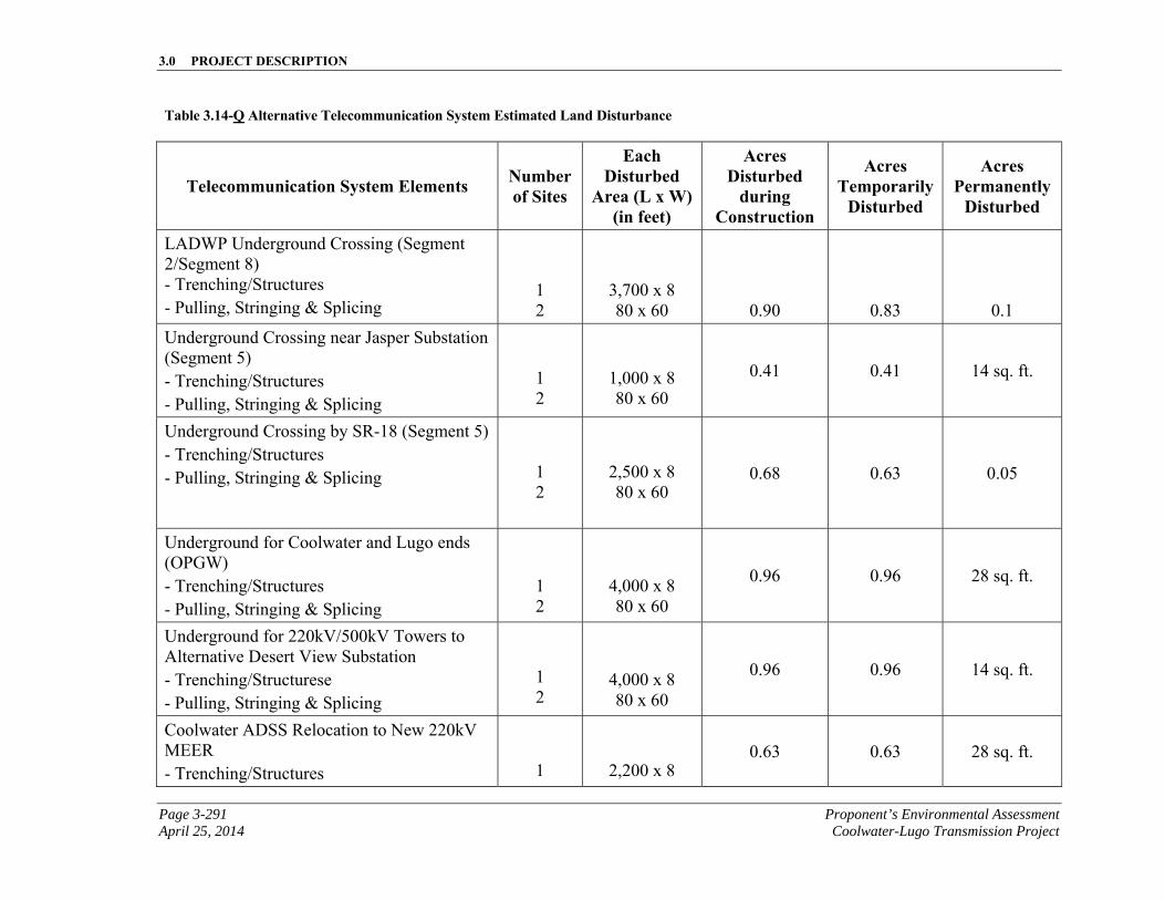
3.0 PROJECT DESCRIPTION
Page 3-291 Proponent’s Environmental Assessment April 25, 2014 Coolwater-Lugo Transmission Project
Table 3.14-Q Alternative Telecommunication System Estimated Land Disturbance
Telecommunication System Elements Number of Sites
Each Disturbed
Area (L x W) (in feet)
Acres Disturbed
during Construction
Acres Temporarily
Disturbed
Acres Permanently
Disturbed
LADWP Underground Crossing (Segment 2/Segment 8) - Trenching/Structures - Pulling, Stringing & Splicing
1 2
3,700 x 8 80 x 60 0.90 0.83 0.1
Underground Crossing near Jasper Substation (Segment 5) - Trenching/Structures - Pulling, Stringing & Splicing
1 2
1,000 x 8 80 x 60
0.41 0.41 14 sq. ft.
Underground Crossing by SR-18 (Segment 5) - Trenching/Structures - Pulling, Stringing & Splicing
1 2
2,500 x 8 80 x 60
0.68 0.63 0.05
Underground for Coolwater and Lugo ends (OPGW) - Trenching/Structures - Pulling, Stringing & Splicing
1 2
4,000 x 8 80 x 60
0.96 0.96 28 sq. ft.
Underground for 220kV/500kV Towers to Alternative Desert View Substation - Trenching/Structurese - Pulling, Stringing & Splicing
1 2
4,000 x 8 80 x 60
0.96 0.96 14 sq. ft.
Coolwater ADSS Relocation to New 220kV MEER - Trenching/Structures
1
2,200 x 8 0.63 0.63 28 sq. ft.
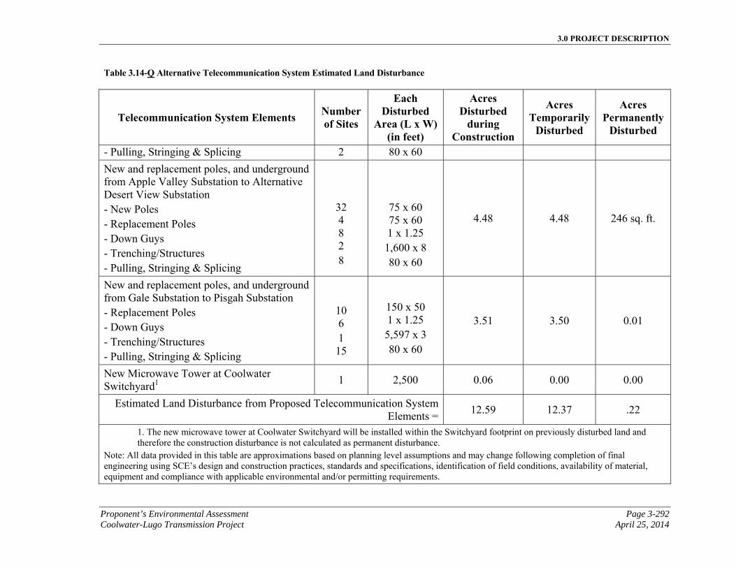
3.0 PROJECT DESCRIPTION
Proponent’s Environmental Assessment Page 3-292 Coolwater-Lugo Transmission Project April 25, 2014
Table 3.14-Q Alternative Telecommunication System Estimated Land Disturbance
Telecommunication System Elements Number of Sites
Each Disturbed
Area (L x W) (in feet)
Acres Disturbed
during Construction
Acres Temporarily
Disturbed
Acres Permanently
Disturbed
- Pulling, Stringing & Splicing 2 80 x 60
New and replacement poles, and underground from Apple Valley Substation to Alternative Desert View Substation - New Poles - Replacement Poles - Down Guys - Trenching/Structures - Pulling, Stringing & Splicing
32 4 8 2 8
75 x 60 75 x 60 1 x 1.25 1,600 x 8 80 x 60
4.48 4.48 246 sq. ft.
New and replacement poles, and underground from Gale Substation to Pisgah Substation - Replacement Poles - Down Guys - Trenching/Structures - Pulling, Stringing & Splicing
10 6 1 15
150 x 50 1 x 1.25 5,597 x 3 80 x 60
3.51 3.50 0.01
New Microwave Tower at Coolwater Switchyard1
1 2,500 0.06 0.00 0.00
Estimated Land Disturbance from Proposed Telecommunication System Elements =
12.59 12.37 .22
1. The new microwave tower at Coolwater Switchyard will be installed within the Switchyard footprint on previously disturbed land and therefore the construction disturbance is not calculated as permanent disturbance.
Note: All data provided in this table are approximations based on planning level assumptions and may change following completion of final engineering using SCE’s design and construction practices, standards and specifications, identification of field conditions, availability of material, equipment and compliance with applicable environmental and/or permitting requirements.
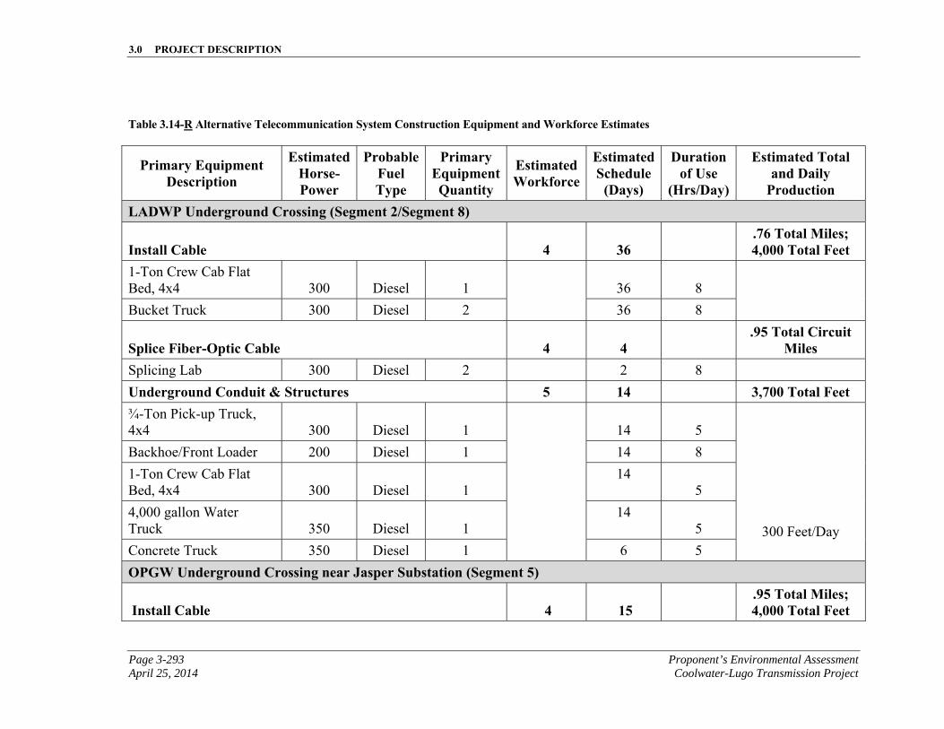
3.0 PROJECT DESCRIPTION
Page 3-293 Proponent’s Environmental Assessment April 25, 2014 Coolwater-Lugo Transmission Project
Table 3.14-R Alternative Telecommunication System Construction Equipment and Workforce Estimates
Primary Equipment Description
Estimated Horse-Power
Probable Fuel Type
Primary Equipment Quantity
Estimated Workforce
Estimated Schedule
(Days)
Duration of Use
(Hrs/Day)
Estimated Total and Daily
Production LADWP Underground Crossing (Segment 2/Segment 8)
Install Cable 4 36 .76 Total Miles; 4,000 Total Feet
1-Ton Crew Cab Flat Bed, 4x4 300 Diesel 1 36 8
Bucket Truck 300 Diesel 2 36 8
Splice Fiber-Optic Cable 4 4 .95 Total Circuit
Miles Splicing Lab 300 Diesel 2 2 8
Underground Conduit & Structures 5 14 3,700 Total Feet ¾-Ton Pick-up Truck, 4x4 300 Diesel 1
14 5
300 Feet/Day
Backhoe/Front Loader 200 Diesel 1 14 8
1-Ton Crew Cab Flat Bed, 4x4 300 Diesel 1
14 5
4,000 gallon Water Truck 350 Diesel 1
14 5
Concrete Truck 350 Diesel 1 6 5
OPGW Underground Crossing near Jasper Substation (Segment 5)
Install Cable 4 15 .95 Total Miles; 4,000 Total Feet
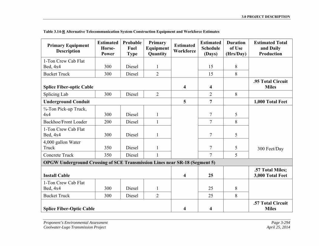
3.0 PROJECT DESCRIPTION
Proponent’s Environmental Assessment Page 3-294 Coolwater-Lugo Transmission Project April 25, 2014
Table 3.14-R Alternative Telecommunication System Construction Equipment and Workforce Estimates
Primary Equipment Description
Estimated Horse-Power
Probable Fuel Type
Primary Equipment Quantity
Estimated Workforce
Estimated Schedule
(Days)
Duration of Use
(Hrs/Day)
Estimated Total and Daily
Production 1-Ton Crew Cab Flat Bed, 4x4 300 Diesel 1 15 8
Bucket Truck 300 Diesel 2 15 8
Splice Fiber-optic Cable 4 4 .95 Total Circuit
Miles Splicing Lab 300 Diesel 2 2 8
Underground Conduit 5 7 1,000 Total Feet ¾-Ton Pick-up Truck, 4x4 300 Diesel 1 7 5
300 Feet/Day
Backhoe/Front Loader 200 Diesel 1 7 8
1-Ton Crew Cab Flat Bed, 4x4 300 Diesel 1 7 5
4,000 gallon Water Truck 350 Diesel 1 7 5
Concrete Truck 350 Diesel 1 7 5
OPGW Underground Crossing of SCE Transmission Lines near SR-18 (Segment 5)
Install Cable 4 25 .57 Total Miles; 3,000 Total Feet
1-Ton Crew Cab Flat Bed, 4x4 300 Diesel 1 25 8
Bucket Truck 300 Diesel 2 25 8
Splice Fiber-Optic Cable 4 4 .57 Total Circuit
Miles
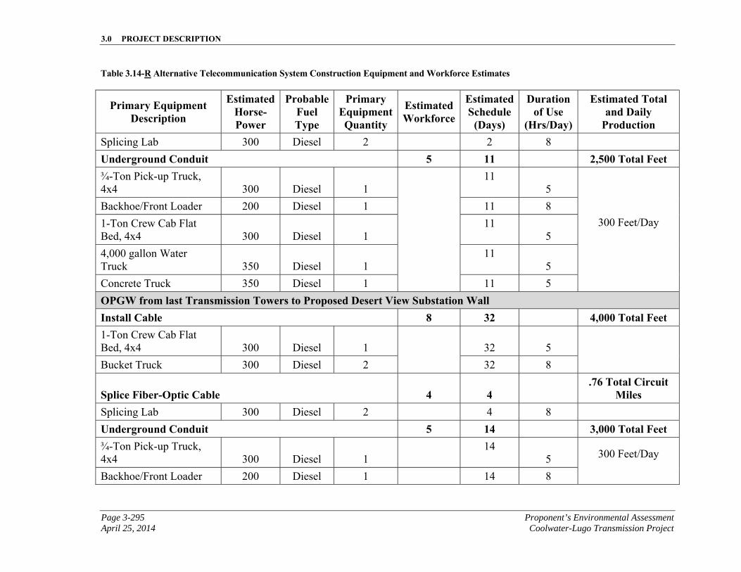
3.0 PROJECT DESCRIPTION
Page 3-295 Proponent’s Environmental Assessment April 25, 2014 Coolwater-Lugo Transmission Project
Table 3.14-R Alternative Telecommunication System Construction Equipment and Workforce Estimates
Primary Equipment Description
Estimated Horse-Power
Probable Fuel Type
Primary Equipment Quantity
Estimated Workforce
Estimated Schedule
(Days)
Duration of Use
(Hrs/Day)
Estimated Total and Daily
Production Splicing Lab 300 Diesel 2 2 8
Underground Conduit 5 11 2,500 Total Feet ¾-Ton Pick-up Truck, 4x4 300 Diesel 1
11 5
300 Feet/Day
Backhoe/Front Loader 200 Diesel 1 11 8
1-Ton Crew Cab Flat Bed, 4x4 300 Diesel 1
11 5
4,000 gallon Water Truck 350 Diesel 1
11 5
Concrete Truck 350 Diesel 1 11 5
OPGW from last Transmission Towers to Proposed Desert View Substation Wall Install Cable 8 32 4,000 Total Feet 1-Ton Crew Cab Flat Bed, 4x4 300 Diesel 1 32 5
Bucket Truck 300 Diesel 2 32 8
Splice Fiber-Optic Cable 4 4 .76 Total Circuit
Miles Splicing Lab 300 Diesel 2 4 8
Underground Conduit 5 14 3,000 Total Feet ¾-Ton Pick-up Truck, 4x4 300 Diesel 1
14 5 300 Feet/Day
Backhoe/Front Loader 200 Diesel 1 14 8
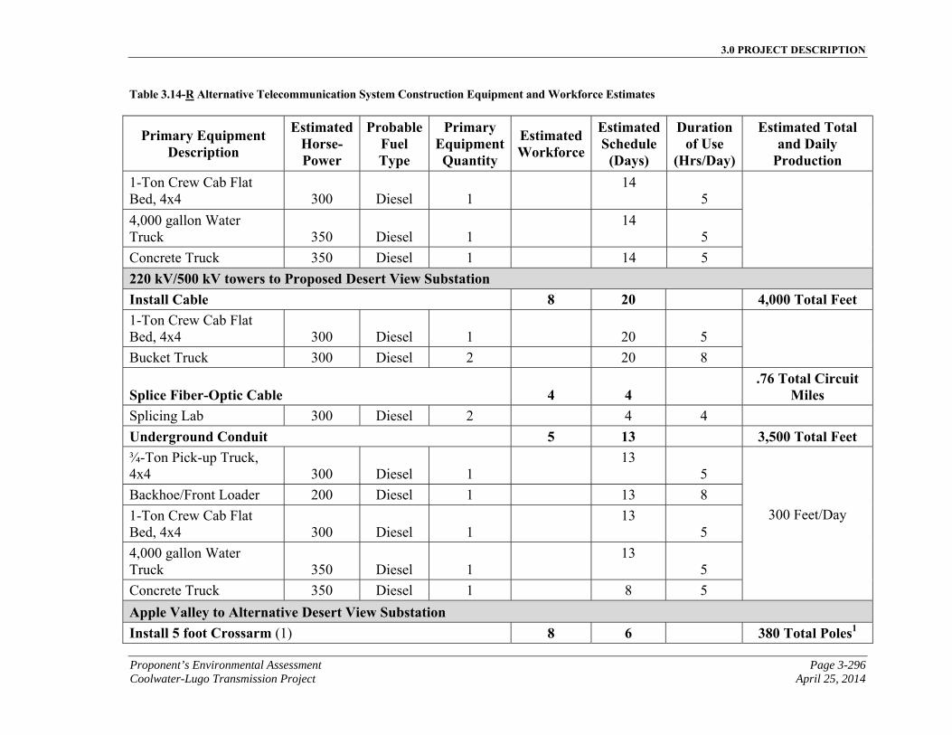
3.0 PROJECT DESCRIPTION
Proponent’s Environmental Assessment Page 3-296 Coolwater-Lugo Transmission Project April 25, 2014
Table 3.14-R Alternative Telecommunication System Construction Equipment and Workforce Estimates
Primary Equipment Description
Estimated Horse-Power
Probable Fuel Type
Primary Equipment Quantity
Estimated Workforce
Estimated Schedule
(Days)
Duration of Use
(Hrs/Day)
Estimated Total and Daily
Production 1-Ton Crew Cab Flat Bed, 4x4 300 Diesel 1
14 5
4,000 gallon Water Truck 350 Diesel 1
14 5
Concrete Truck 350 Diesel 1 14 5
220 kV/500 kV towers to Proposed Desert View Substation Install Cable 8 20 4,000 Total Feet 1-Ton Crew Cab Flat Bed, 4x4 300 Diesel 1 20 5
Bucket Truck 300 Diesel 2 20 8
Splice Fiber-Optic Cable 4 4 .76 Total Circuit
Miles Splicing Lab 300 Diesel 2 4 4
Underground Conduit 5 13 3,500 Total Feet ¾-Ton Pick-up Truck, 4x4 300 Diesel 1
13 5
300 Feet/Day
Backhoe/Front Loader 200 Diesel 1 13 8
1-Ton Crew Cab Flat Bed, 4x4 300 Diesel 1
13 5
4,000 gallon Water Truck 350 Diesel 1
13 5
Concrete Truck 350 Diesel 1 8 5
Apple Valley to Alternative Desert View Substation Install 5 foot Crossarm (1) 8 6 380 Total Poles1
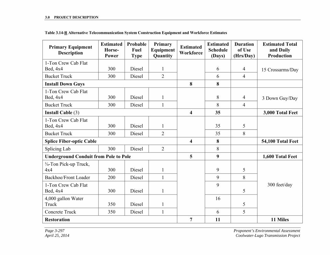
3.0 PROJECT DESCRIPTION
Page 3-297 Proponent’s Environmental Assessment April 25, 2014 Coolwater-Lugo Transmission Project
Table 3.14-R Alternative Telecommunication System Construction Equipment and Workforce Estimates
Primary Equipment Description
Estimated Horse-Power
Probable Fuel Type
Primary Equipment Quantity
Estimated Workforce
Estimated Schedule
(Days)
Duration of Use
(Hrs/Day)
Estimated Total and Daily
Production 1-Ton Crew Cab Flat Bed, 4x4 300 Diesel 1 6 4 15 Crossarms/Day Bucket Truck 300 Diesel 2 6 4
Install Down Guys 8 8 1-Ton Crew Cab Flat Bed, 4x4 300 Diesel 1
8 4 3 Down Guy/Day Bucket Truck 300 Diesel 1 8 4
Install Cable (3) 4 35 3,000 Total Feet 1-Ton Crew Cab Flat Bed, 4x4 300 Diesel 1 35 5
Bucket Truck 300 Diesel 2 35 8
Splice Fiber-optic Cable 4 8 54,100 Total Feet Splicing Lab 300 Diesel 2 8
Underground Conduit from Pole to Pole 5 9 1,600 Total Feet ¾-Ton Pick-up Truck, 4x4 300 Diesel 1
9 5
300 feet/day
Backhoe/Front Loader 200 Diesel 1 9 8
1-Ton Crew Cab Flat Bed, 4x4 300 Diesel 1
9 5
4,000 gallon Water Truck 350 Diesel 1
16 5
Concrete Truck 350 Diesel 1 6 5
Restoration 7 11 11 Miles
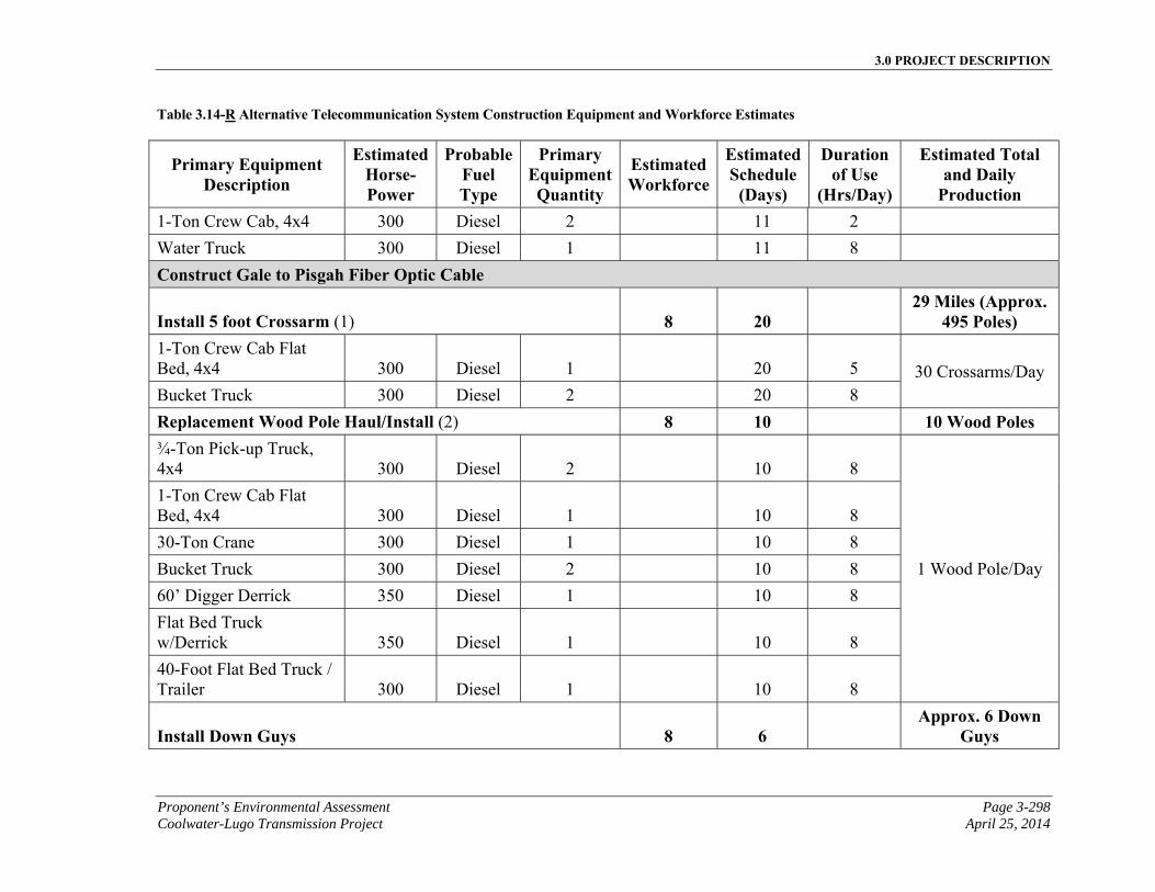
3.0 PROJECT DESCRIPTION
Proponent’s Environmental Assessment Page 3-298 Coolwater-Lugo Transmission Project April 25, 2014
Table 3.14-R Alternative Telecommunication System Construction Equipment and Workforce Estimates
Primary Equipment Description
Estimated Horse-Power
Probable Fuel Type
Primary Equipment Quantity
Estimated Workforce
Estimated Schedule
(Days)
Duration of Use
(Hrs/Day)
Estimated Total and Daily
Production 1-Ton Crew Cab, 4x4 300 Diesel 2 11 2
Water Truck 300 Diesel 1 11 8
Construct Gale to Pisgah Fiber Optic Cable
Install 5 foot Crossarm (1) 8 20 29 Miles (Approx.
495 Poles) 1-Ton Crew Cab Flat Bed, 4x4 300 Diesel 1 20 5 30 Crossarms/Day Bucket Truck 300 Diesel 2 20 8
Replacement Wood Pole Haul/Install (2) 8 10 10 Wood Poles ¾-Ton Pick-up Truck, 4x4 300 Diesel 2 10 8
1 Wood Pole/Day
1-Ton Crew Cab Flat Bed, 4x4 300 Diesel 1 10 8
30-Ton Crane 300 Diesel 1 10 8
Bucket Truck 300 Diesel 2 10 8
60’ Digger Derrick 350 Diesel 1 10 8
Flat Bed Truck w/Derrick 350 Diesel 1 10 8
40-Foot Flat Bed Truck / Trailer 300 Diesel 1 10 8
Install Down Guys 8 6 Approx. 6 Down
Guys
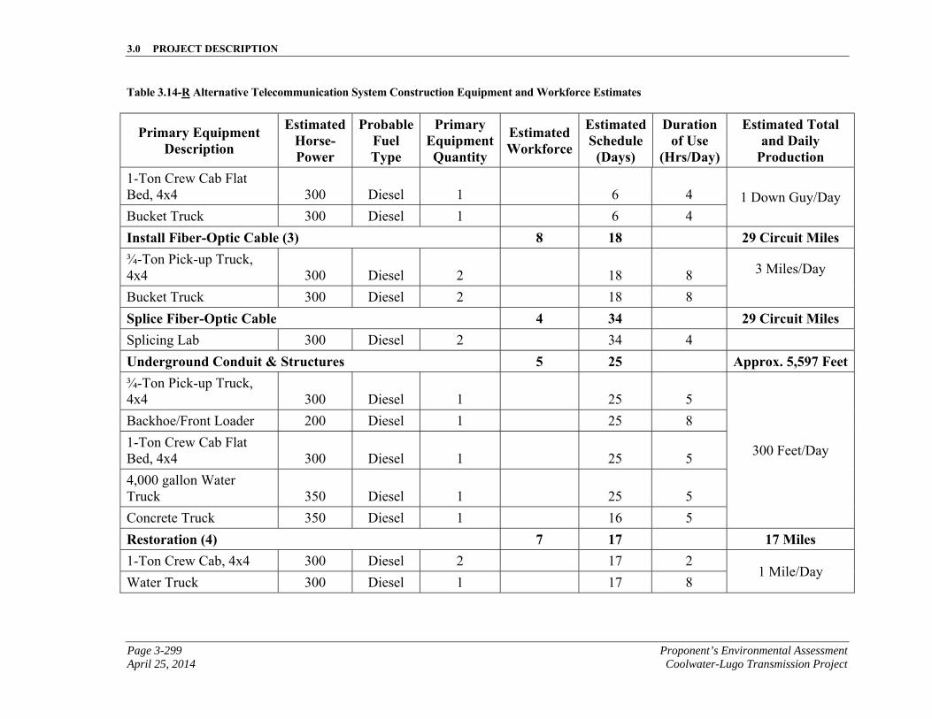
3.0 PROJECT DESCRIPTION
Page 3-299 Proponent’s Environmental Assessment April 25, 2014 Coolwater-Lugo Transmission Project
Table 3.14-R Alternative Telecommunication System Construction Equipment and Workforce Estimates
Primary Equipment Description
Estimated Horse-Power
Probable Fuel Type
Primary Equipment Quantity
Estimated Workforce
Estimated Schedule
(Days)
Duration of Use
(Hrs/Day)
Estimated Total and Daily
Production 1-Ton Crew Cab Flat Bed, 4x4 300 Diesel 1 6 4 1 Down Guy/Day Bucket Truck 300 Diesel 1 6 4
Install Fiber-Optic Cable (3) 8 18 29 Circuit Miles ¾-Ton Pick-up Truck, 4x4 300 Diesel 2 18 8 3 Miles/Day
Bucket Truck 300 Diesel 2 18 8
Splice Fiber-Optic Cable 4 34 29 Circuit Miles Splicing Lab 300 Diesel 2 34 4
Underground Conduit & Structures 5 25 Approx. 5,597 Feet¾-Ton Pick-up Truck, 4x4 300 Diesel 1 25 5
300 Feet/Day
Backhoe/Front Loader 200 Diesel 1 25 8
1-Ton Crew Cab Flat Bed, 4x4 300 Diesel 1 25 5
4,000 gallon Water Truck 350 Diesel 1 25 5
Concrete Truck 350 Diesel 1 16 5
Restoration (4) 7 17 17 Miles 1-Ton Crew Cab, 4x4 300 Diesel 2 17 2
1 Mile/Day Water Truck 300 Diesel 1 17 8
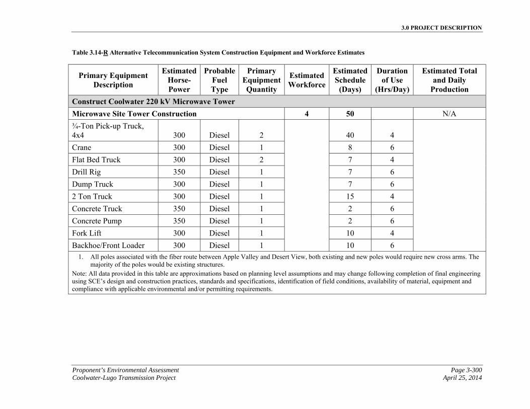
3.0 PROJECT DESCRIPTION
Proponent’s Environmental Assessment Page 3-300 Coolwater-Lugo Transmission Project April 25, 2014
Table 3.14-R Alternative Telecommunication System Construction Equipment and Workforce Estimates
Primary Equipment Description
Estimated Horse-Power
Probable Fuel Type
Primary Equipment Quantity
Estimated Workforce
Estimated Schedule
(Days)
Duration of Use
(Hrs/Day)
Estimated Total and Daily
Production Construct Coolwater 220 kV Microwave Tower Microwave Site Tower Construction 4 50 N/A
¾-Ton Pick-up Truck, 4x4 300 Diesel 2
40 4
Crane 300 Diesel 1 8 6
Flat Bed Truck 300 Diesel 2 7 4
Drill Rig 350 Diesel 1 7 6
Dump Truck 300 Diesel 1 7 6
2 Ton Truck 300 Diesel 1 15 4
Concrete Truck 350 Diesel 1 2 6
Concrete Pump 350 Diesel 1 2 6
Fork Lift 300 Diesel 1 10 4
Backhoe/Front Loader 300 Diesel 1 10 6 1. All poles associated with the fiber route between Apple Valley and Desert View, both existing and new poles would require new cross arms. The
majority of the poles would be existing structures. Note: All data provided in this table are approximations based on planning level assumptions and may change following completion of final engineering using SCE’s design and construction practices, standards and specifications, identification of field conditions, availability of material, equipment and compliance with applicable environmental and/or permitting requirements.
3.0 PROJECT DESCRIPTION
Page 3-301 Proponent’s Environmental Assessment April 25, 2014 Coolwater-Lugo Transmission Project
3.14.9 Alternative Project Land Disturbance Summary
Table 3.14-QS, Alternative Project Estimated Land Disturbance provides a summary of the land disturbance estimates associated with the Alternative Project.
3.0 PROJECT DESCRIPTION
Proponent’s Environmental Assessment Page 3-302 Coolwater-Lugo Transmission Project April 25, 2014
This page is intentionally blank
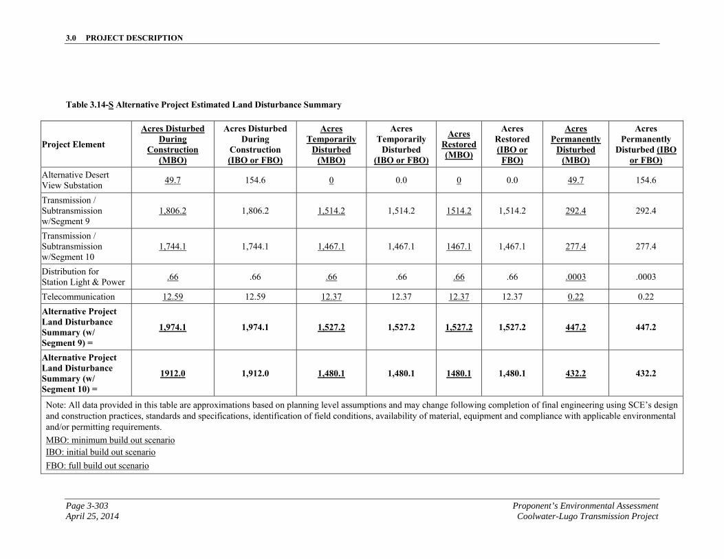
3.0 PROJECT DESCRIPTION
Page 3-303 Proponent’s Environmental Assessment April 25, 2014 Coolwater-Lugo Transmission Project
Table 3.14-S Alternative Project Estimated Land Disturbance Summary
Project Element
Acres Disturbed During
Construction (MBO)
Acres Disturbed During
Construction (IBO or FBO)
Acres Temporarily
Disturbed (MBO)
Acres Temporarily
Disturbed (IBO or FBO)
Acres Restored (MBO)
Acres Restored (IBO or FBO)
Acres Permanently
Disturbed (MBO)
Acres Permanently
Disturbed (IBO or FBO)
Alternative Desert View Substation
49.7 154.6 0 0.0 0 0.0 49.7 154.6
Transmission / Subtransmission w/Segment 9
1,806.2 1,806.2 1,514.2 1,514.2 1514.2 1,514.2 292.4 292.4
Transmission / Subtransmission w/Segment 10
1,744.1 1,744.1 1,467.1 1,467.1 1467.1 1,467.1 277.4 277.4
Distribution for Station Light & Power
.66 .66 .66 .66 .66 .66 .0003 .0003
Telecommunication 12.59 12.59 12.37 12.37 12.37 12.37 0.22 0.22
Alternative Project Land Disturbance Summary (w/ Segment 9) =
1,974.1 1,974.1 1,527.2 1,527.2 1,527.2 1,527.2 447.2 447.2
Alternative Project Land Disturbance Summary (w/ Segment 10) =
1912.0 1,912.0 1,480.1 1,480.1 1480.1 1,480.1 432.2 432.2
Note: All data provided in this table are approximations based on planning level assumptions and may change following completion of final engineering using SCE’s design and construction practices, standards and specifications, identification of field conditions, availability of material, equipment and compliance with applicable environmental and/or permitting requirements.
MBO: minimum build out scenario IBO: initial build out scenario
FBO: full build out scenario

3.0 PROJECT DESCRIPTION
Proponent’s Environmental Assessment Page 3-304 Coolwater-Lugo Transmission Project April 25, 2014
This page is intentionally blank
3.0 PROJECT DESCRIPTION
Page 3-305 Proponent’s Environmental Assessment April 25, 2014 Coolwater-Lugo Transmission Project
3.15 Alternative Project Construction Equipment and Personnel
The estimated elements, materials, and number of personnel and equipment required for construction of the Alternative Project are summarized for each project component in their respective Construction Equipment and Workforce Estimates Table detailed in above sections.
Construction methods would be as described for the Proposed Project in Section 3.11, Construction Equipment and Personnel. For the Alternative Project, SCE anticipates a total of approximately 600 construction personnel working on any given day. SCE anticipates that crews would work concurrently whenever possible; however, the estimated deployment and number of crew members would vary depending on factors such as material availability, resource availability, and construction scheduling.
3.16 Alternative Project Construction Schedule
SCE anticipates that construction of the Alternative Project would take approximately 30 months. Construction would commence following CPUC approval, final engineering, procurement activities, and receipt of all applicable permits.
BEFORE THE PUBLIC UTILITIES COMMISSION OF THE STATE OF CALIFORNIA
In the Matter of the Application of SOUTHERN ) CALIFORNIA EDISON COMPANY (U 338-E) ) Application No. 13-08-023 for a Certificate of Public Convenience and ) (Filed August 28, 2013) Necessity for the Coolwater-Lugo Transmission ) Project )
CERTIFICATE OF SERVICE
I hereby certify that, pursuant to the Commission’s Rules of Practice and Procedure, I have this day served a true copy of THE AMENDED EXECUTIVE SUMMARY, CHAPTER 1 PURPOSE AND NEED, AND CHAPTER 3 PROJECT DESCRIPTION on all parties identified on the attached service list(s) A.13-08-023. Service was effected by one or more means indicated below:
☒ Transmitting the copies via e-mail to all parties who have provided an e-mail
address to the CPUC Official Service List for A.13-08-023.
☒ Placing the copies in sealed envelopes and causing such envelopes to be delivered
by hand or by overnight courier to the offices of the assigned Administrative Law Judge(s) and other addressees.
ALJ Irene K. Moosen Commissioner Michel Peter Florio CPUC CPUC 505 Van Ness Ave. 505 Van Ness Ave. San Francisco, CA 94102 San Francisco, CA 94102
Executed this 25TH day of April 2014, at Rosemead, California.
/s/Monica L. Romero ___________________ Monica L. Romero Project Analyst SOUTHERN CALIFORNIA EDISON COMPANY
2244 Walnut Grove Avenue Post Office Box 800 Rosemead, California 91770
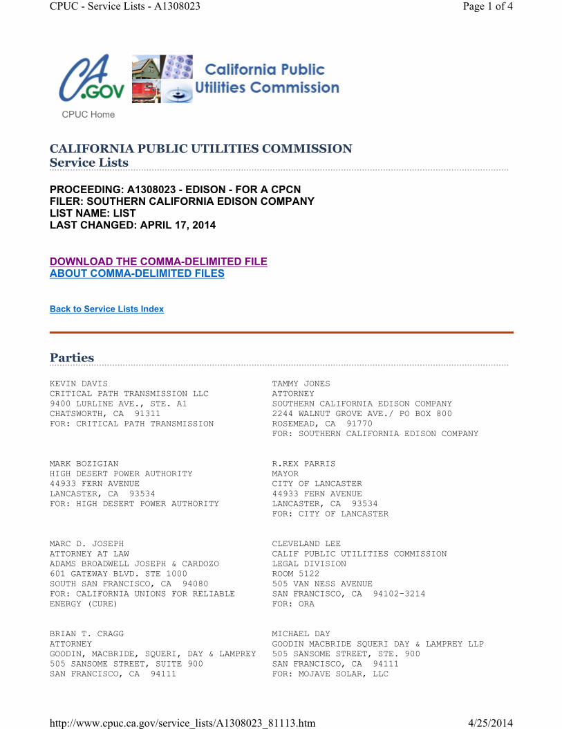
PROCEEDING: A1308023 - EDISON - FOR A CPCN FILER: SOUTHERN CALIFORNIA EDISON COMPANY LIST NAME: LIST LAST CHANGED: APRIL 17, 2014
DOWNLOAD THE COMMA-DELIMITED FILE ABOUT COMMA-DELIMITED FILES
Back to Service Lists Index
KEVIN DAVIS TAMMY JONES CRITICAL PATH TRANSMISSION LLC ATTORNEY 9400 LURLINE AVE., STE. A1 SOUTHERN CALIFORNIA EDISON COMPANY CHATSWORTH, CA 91311 2244 WALNUT GROVE AVE./ PO BOX 800 FOR: CRITICAL PATH TRANSMISSION ROSEMEAD, CA 91770 FOR: SOUTHERN CALIFORNIA EDISON COMPANY MARK BOZIGIAN R.REX PARRIS HIGH DESERT POWER AUTHORITY MAYOR 44933 FERN AVENUE CITY OF LANCASTER LANCASTER, CA 93534 44933 FERN AVENUE FOR: HIGH DESERT POWER AUTHORITY LANCASTER, CA 93534 FOR: CITY OF LANCASTER MARC D. JOSEPH CLEVELAND LEE ATTORNEY AT LAW CALIF PUBLIC UTILITIES COMMISSION ADAMS BROADWELL JOSEPH & CARDOZO LEGAL DIVISION 601 GATEWAY BLVD. STE 1000 ROOM 5122 SOUTH SAN FRANCISCO, CA 94080 505 VAN NESS AVENUE FOR: CALIFORNIA UNIONS FOR RELIABLE SAN FRANCISCO, CA 94102-3214 ENERGY (CURE) FOR: ORA BRIAN T. CRAGG MICHAEL DAY ATTORNEY GOODIN MACBRIDE SQUERI DAY & LAMPREY LLP GOODIN, MACBRIDE, SQUERI, DAY & LAMPREY 505 SANSOME STREET, STE. 900 505 SANSOME STREET, SUITE 900 SAN FRANCISCO, CA 94111 SAN FRANCISCO, CA 94111 FOR: MOJAVE SOLAR, LLC
CPUC Home
CALIFORNIA PUBLIC UTILITIES COMMISSION Service Lists
Parties
Page 1 of 4CPUC - Service Lists - A1308023
4/25/2014http://www.cpuc.ca.gov/service_lists/A1308023_81113.htm
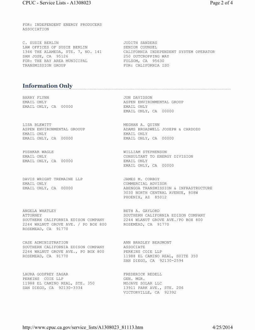
FOR: INDEPENDENT ENERGY PRODUCERS ASSOCIATION C. SUSIE BERLIN JUDITH SANDERS LAW OFFICES OF SUSIE BERLIN SENIOR COUNSEL 1346 THE ALAMEDA, STE. 7, NO. 141 CALIFORNIA INDEPENDENT SYSTEM OPERATOR SAN JOSE, CA 95126 250 OUTCROPPING WAY FOR: THE BAY AREA MUNICIPAL FOLSOM, CA 95630 TRANSMISSION GROUP FOR: CALIFORNIA ISO
BARRY FLYNN JON DAVIDSON EMAIL ONLY ASPEN ENVIRONMENTAL GROUP EMAIL ONLY, CA 00000 EMAIL ONLY EMAIL ONLY, CA 00000 LISA BLEWITT MEGHAN A. QUINN ASPEN ENVIRONMENTAL GROOUP ADAMS BROADWELL JOSEPH & CARDOZO EMAIL ONLY EMAIL ONLY EMAIL ONLY, CA 00000 EMAIL ONLY, CA 00000 PUSHKAR WAGLE WILLIAM STEPHENSON EMAIL ONLY CONSULTANT TO ENERGY DIVISION EMAIL ONLY, CA 00000 EMAIL ONLY EMAIL ONLY, CA 00000 DAVIS WRIGHT TREMAINE LLP JAMES M. CORBOY EMAIL ONLY COMMERCIAL ADVISOR EMAIL ONLY, CA 00000 ABENGOA TRANSMISSION & INFRASTRUCTURE 3030 NORTH CENTRAL AVENUE, 808W PHOENIX, AZ 85012 ANGELA WHATLEY BETH A. GAYLORD ATTORNEY SOUTHERN CALIFORNIA EDISON COMPANY SOUTHERN CALIFORNIA EDISON COMPANY 2244 WLANUT GROVE AVE./PO BOX 800 2244 WALNUT GROVE AVE. / PO BOX 800 ROSEMEAD, CA 91770 ROSEMEAD, CA 91770 CASE ADMINISTRATION ANN BRADLEY BEAUMONT SOUTHERN CALIFORNIA EDISON COMPANY ASSOCIATE 2244 WALNUT GROVE AVE., PO BOX 800 PERKINS COIE LLP ROSEMEAD, CA 91770 11988 EL CAMINO REAL, SUITE 350 SAN DIEGO, CA 92130-2594 LAURA GODFREY ZAGAR FREDERICK REDELL PERKINS COIE LLP GEN. MGR. 11988 EL CAMINO REAL, STE. 350 MOJAVE SOLAR LLC SAN DIEGO, CA 92130-3334 13911 PARK AVE., STE. 206 VICTORVILLE, CA 92392
Information Only
Page 2 of 4CPUC - Service Lists - A1308023
4/25/2014http://www.cpuc.ca.gov/service_lists/A1308023_81113.htm
JAMIE L. MAULDIN MICHAEL A. HYAMS ADAMS BROADWELL JOSEPH & CARDOZO POWER ENTERPRISE-REGULATORY AFFAIRS 601 GATEWAY BLVD., STE. 1000 SAN FRANCISCO PUBLIC UTILITIES COMM SO. SAN FRANCISCO, CA 94080 525 GOLDEN GATE AVE., 7TH FLOOR FOR: CALIFORNIA UNIONS FOR RELIABEL SAN FRANCISCO, CA 94102-3220 ENERGY (CURE) WILLIAM K. SANDERS JEFFREY P. GRAY DEPUTY CITY ATTORNEY DAVIS WRIGHT TREMAINE, LLP CITY AND COUNTY OF SAN FRANCISCO 505 MONTGOMERY STREET, SUITE 800 1 DR. CARLTON B. GOODLETT PL., RM 234 SAN FRANCISCO, CA 94111-6533 SAN FRANCISCO, CA 94102-4682 CALIFORNIA ENERGY MARKETS ROBERT JENKINS 425 DIVISADERO ST STE 303 FLYNN RCI SAN FRANCISCO, CA 94117-2242 5440 EDGEVIEW DRIVE DISCOVERY BAY, CA 94505 FOR: THE BAY AREA MUNICIPAL TRANSMISSION GROUP PHILLIP MULLER JUDITH B. SANDERS PRESIDENT SR. COUNSEL SCD ENERGY SOLUTIONS CALIF. INDEPENDENT SYSTEM OPERATOR CORP 436 NOVA ALBION WAY 250 OUTCROPPING WAY SAN RAFAEL, CA 94903 FOLSOM, CA 95630 STEVEN KELLY POLICY DIRECTOR INDEPENDENT ENERGY PRODUCERS ASSCIATION 1215 K STREET, STE. 900 SACRAMENTO, CA 95814
JASON COONTZ MERIDETH STERKEL CPUC CALIFORNIA PUBLIC UTILITIES COMMISSION ENERGY DIVISION EMAIL ONLY EMAIL ONLY EMAIL ONLY, CA 00000 EMAIL ONLY, CA 00000 WILLIAM DIETRICH ANDREW BARNSDALE SR ANALYST CALIF PUBLIC UTILITIES COMMISSION CPUC - ENERGY DIV. INFRASTRUCTURE PLANNING AND PERMITTING B 505 VAN NESS AVE. RM. 4006 AREA 4-A SAN FRANCISCO, CA 94102 505 VAN NESS AVENUE SAN FRANCISCO, CA 94102-3214 CHARLES MEE CHRISTOPHER MYERS CALIF PUBLIC UTILITIES COMMISSION CALIF PUBLIC UTILITIES COMMISSION ELECTRICITY PLANNING & POLICY BRANCH ELECTRICITY PLANNING & POLICY BRANCH ROOM 4102 ROOM 4104 505 VAN NESS AVENUE 505 VAN NESS AVENUE SAN FRANCISCO, CA 94102-3214 SAN FRANCISCO, CA 94102-3214
State Service
Page 3 of 4CPUC - Service Lists - A1308023
4/25/2014http://www.cpuc.ca.gov/service_lists/A1308023_81113.htm
IRENE K. MOOSEN JOSE ALIAGA-CARO CALIF PUBLIC UTILITIES COMMISSION CALIF PUBLIC UTILITIES COMMISSION DIVISION OF ADMINISTRATIVE LAW JUDGES ELECTRICITY PLANNING & POLICY BRANCH ROOM 5103 AREA 505 VAN NESS AVENUE 505 VAN NESS AVENUE SAN FRANCISCO, CA 94102-3214 SAN FRANCISCO, CA 94102-3214 JOSEPH A. ABHULIMEN JULIE A. FITCH CALIF PUBLIC UTILITIES COMMISSION CALIF PUBLIC UTILITIES COMMISSION ELECTRICITY PLANNING & POLICY BRANCH EXECUTIVE DIVISION ROOM 4209 ROOM 5214 505 VAN NESS AVENUE 505 VAN NESS AVENUE SAN FRANCISCO, CA 94102-3214 SAN FRANCISCO, CA 94102-3214
TOP OF PAGE BACK TO INDEX OF SERVICE LISTS
Page 4 of 4CPUC - Service Lists - A1308023
4/25/2014http://www.cpuc.ca.gov/service_lists/A1308023_81113.htm