Embed Size (px)
Citation preview

The Ambient Computational EnvironmentsArchitecture for Reliable, Secure,
and Pervasive Computing
Renzo Hayashi, Leon Searl, and Gary Minden
ITTC-FY2002-TR-23150-01
April 2002
Copyright © 2002:The University of Kansas Center for Research, Inc.,2335 Irving Hill Road, Lawrence, KS 66044-7612.All rights reserved.
Project Sponsor:U.S. Air Force and the Defense Advanced Research
Projects Agency under contract no. F30602-00-2-0581and The National Science Foundation
under grant EIA-9972843
Technical Report
The University of Kansas

Abstract
During the past few years, the technology world has become more and more
geared towards the next generation of Internet connectivity. How to integrate a
myriad of devices and technologies into one easily accessible network of user-
friendly computational resource became the next challenge.
The ACE - Ambient Computational Environments - architecture aims at high-
scale and seamless integration of services (which can be defined as user applications
or programs) and devices within a secure network and onto a robust framework. This
architecture also allows for easy introduction of new services and devices, enabling
the environment to adapt to new technologies and user needs. Such environments
allow users to interact with it and to access computational resources from anywhere at
the touch of a button or with a spoken command. The ACE infrastructure consists
mainly of ACE service daemons, which are the building blocks of ACE services.
These daemons, along with a secure, reliable, and persistent state storage comprise
the basis of the ACE system architecture.
This study is intended to outline the architecture of the ACE project, to
illustrate the usefulness of ACE and its applications, and obtain some insight from
other similar projects in academia and businesses as to how feasible and worthwhile
the ACE approach is.

ii
Contents
LIST OF FIGURES .................................................................................................. IV
1 INTRODUCTION............................................................................................... 1 1.1 ACE SERVICES AND ACE USERS .................................................................. 3 1.2 HUMAN INTERACTION WITHIN ACE.............................................................. 4 1.3 ACE USER WORKSPACES .............................................................................. 8
2 ACE SERVICE DAEMON INFRASTRUCTURE.......................................... 9 2.1 THE ACE SERVICE DAEMON ....................................................................... 10
2.1.1 Daemon Design................................................................................... 11 2.2 ACE SERVICE COMMAND LANGUAGE......................................................... 13 2.3 ACE SERVICE DAEMON HIERARCHY & SERVICE IMPLEMENTATION........... 16 2.4 SERVICE DISCOVERY – ACE SERVICE DIRECTORY ..................................... 18 2.5 ACE DAEMON NOTIFICATIONS.................................................................... 21 2.6 DAEMON STARTUP....................................................................................... 23
3 ACE SECURITY AND AUTHENTICATION .............................................. 26 3.1 ACE COMMUNICATIONS.............................................................................. 26 3.2 ACE SERVICE ACCESS AND AUTHENTICATION ........................................... 27
4 BASIC ACE SERVICES.................................................................................. 30 4.1 HRM – HOST RESOURCE MONITOR ............................................................ 31 4.2 SRM – SYSTEM RESOURCE MONITOR......................................................... 31 4.3 HAL – HOST APPLICATION LAUNCHER....................................................... 32 4.4 SAL – SYSTEM APPLICATION LAUNCHER ................................................... 33 4.5 WSS – WORKSPACE SERVER....................................................................... 33 4.6 ACE ID MONITOR SERVICE ........................................................................ 34 4.7 AUD – ACE USER DATABASE SERVICE ..................................................... 35 4.8 ACE FIU – FINGERPRINT IDENTIFICATION UNIT......................................... 36 4.9 ACE IBUTTON READER SERVICE ................................................................ 37 4.10 ACE AUTHORIZATION DATABASE SERVICE ................................................ 37 4.11 ACE ROOM DATABASE SERVICE................................................................. 38 4.12 ACE CONVERTER SERVICE.......................................................................... 39 4.13 ACE DISTRIBUTION SERVICE ...................................................................... 40 4.14 ACE NETWORK LOGGER SERVICE .............................................................. 41

iii
4.15 A HIGH-LEVEL SERVICE EXAMPLE.............................................................. 41
5 ACE USER APPLICATIONS ......................................................................... 45 5.1 TEMPORARY APPLICATIONS......................................................................... 45 5.2 RESTART APPLICATIONS .............................................................................. 46 5.3 ROBUST APPLICATIONS................................................................................ 47 5.4 VNC & ACE USER WORKSPACES .............................................................. 48 5.5 O-PHONE & ACE COMMUNICATIONS ......................................................... 50
6 ACE PERSISTENT STORE............................................................................ 52
7 ACE SCENARIOS............................................................................................ 55 7.1 SCENARIO 1 – NEW USER & USER WORKSPACE ......................................... 55 7.2 SCENARIO 2 – USER IDENTIFICATION .......................................................... 58 7.3 SCENARIO 3 – USER WORKSPACE................................................................ 58 7.4 SCENARIO 4 – MULTIPLE USER WORKSPACES............................................. 60 7.5 SCENARIO 5 – ACE SERVICES & DEVICES .................................................. 61
8 RELATED WORK ........................................................................................... 62 8.1 UC BERKELEY – NINJA PROJECT................................................................. 62 8.2 MIT – OXYGEN PROJECT............................................................................. 66 8.3 IBM CORPORATION – WEBSPHERE ............................................................. 68 8.4 SUN MICROSYSTEMS – JINI.......................................................................... 70
9 IMPROVEMENTS & FUTURE WORK ....................................................... 73
10 CONTRIBUTIONS & INNOVATIONS..................................................... 75 10.1 ACE’S INNOVATIONS................................................................................... 75 10.2 PERSONAL CONTRIBUTIONS......................................................................... 77
11 CONCLUSIONS ........................................................................................... 79
BIBLIOGRAPHY..................................................................................................... 81

iv
List of Figures FIGURE 1: EXAMPLES OF ACE INTERACTION DEVICES....................................................... 5 FIGURE 2: AN EXAMPLE OF AN ACE SERVICE CONTROL GUI. ............................................ 6 FIGURE 3: SOME OTHER ACE USER INTERACTION DEVICES (DSC IBUTTON [12], SONY
FIU [14], COMPAQ IPAC [15], SONY VAIO NOTEBOOKS [16], SONY VAIO PICTUREBOOKS [17]). .................................................................................................. 7
FIGURE 4: HOW ACE SERVICE DAEMONS INTERACT TO PROVIDE COMPLEX
CAPABILITIES AND COMPUTATION.............................................................................. 10 FIGURE 5: HOW ACE COMMANDS ARE BUILT, TRANSMITTED, AND INTERPRETED FOR
ACE DAEMON COMMUNICATIONS. ............................................................................ 15 FIGURE 6: A PART OF THE ACE SERVICE DAEMON HIERARCHY. ..................................... 17 FIGURE 7: AN EXAMPLE OF HOW SERVICES INTERACT WITH THE ASD FOR SERVICE
LOOKUP...................................................................................................................... 20 FIGURE 8: ACE SERVICE NOTIFICATIONS – AN INHERENT ASPECT/CAPABILITY OF ACE
SERVICE DAEMONS. SERVICES KEEP RUNNING LISTS OF WHICH SERVICES TO NOTIFY WHEN CERTAIN COMMANDS HAVE BEEN EXECUTED BY THE DAEMON. ....................... 22
FIGURE 9: A STEP-BY-STEP PROCESS THAT ALL ACE DAEMONS GO THROUGH TO
INITIALIZE THEMSELVES INTO AN ACE. ..................................................................... 24 FIGURE 10: A DEPICTION OF HOW THE ACE SERVICE INFRASTRUCTURE WORKS WITH
AN AUTHENTICATION DATABASE SERVICE TO STORE AND MANAGE KEYNOTE CREDENTIALS AND ASSERTIONS IN ORDER TO VERIFY USER PERMISSIONS AND SYSTEM ACCESS TO ACE SERVICES AND INFORMATION............................................. 28
FIGURE 11: HOW HRM’S WORK TOGETHER WITH A LOCAL NETWORK LEVEL SRM TO
PROVIDE CLIENTS WITH INVISIBLE DISTRIBUTION OF COMPUTATIONAL RESOURCES... 32 FIGURE 12: AN ACE USER DATABASE SERVES AS AN INTERFACE FOR SERVICES
WISHING TO STORE AND/OR ACCESS USER IDENTIFICATION INFORMATION FROM THE DATABASE........................................................................................................... 36

v
FIGURE 13: AN EXAMPLE OF HOW A VIDEO STREAM IS SENT THROUGH AN ACE CONVERTER SERVICE FOR FORMAT CONVERSION BEFORE DATA STORAGE/USAGE..... 40
FIGURE 14: A DEPICTION OF AN ACE DISTRIBUTION SERVICE FORWARDS DATA FROM
ONE SOURCE TO ONE OR MORE ACE SERVICES........................................................... 40 FIGURE 15: AN EXAMPLE OF HOW BASIC ACE SERVICES CAN BE COMBINED TO
PERFORM HIGH-LEVEL AUDIO STREAMING, CONFERENCING, COMMANDING, AND RECORDING. ............................................................................................................... 42
FIGURE 16: HOW VNC WORKS TO PROVIDE VIRTUAL USER WORKSPACE ACCESS FROM
REMOTE ACCESS POINTS AROUND THE NETWORK WHILE RUNNING ON A SEPARATE HOST MACHINE........................................................................................................... 49
FIGURE 17: THE FIRST CONCEPTUAL FRAMEWORK OF HOW A CLUSTER OF THREE
PERSISTENT STORE SERVERS SHALL WORK TOGETHER TO PROVIDE REDUNDANT AND ROBUST STORAGE OF ACE SERVICE AND APPLICATION STATE, PROVIDING THE FOUNDATION FOR ACE ROBUST APPLICATIONS AND SERVICES.................................. 53
FIGURE 18: A DIAGRAM OF HOW ALL ACE SERVICES ARE INTERCONNECTED TO
PROVIDE ACE USERS WITH IDENTIFICATION CAPABILITIES AND USER WORKSPACES. ............................................................................................................ 57
FIGURE 19: THE STEPS EXECUTED BY AN ACE TO VERIFY A USER AND DISPLAY THE
USER’S WORKSPACE AT HIS/HER ACCESS LOCATION. .................................................. 59

1
Chapter 1
Introduction
In today’s world more and more people talk about the next step in Internet
accessibility. Terms such as pervasive computing, wireless Internet access, and
everywhere computing [1][2] are heard. The concept of having computational
resources available to anyone, anywhere, at the touch of a button or the utterance of a
spoken command has been in the minds of many researchers and developers
throughout universities and businesses alike. The consumer world is also constantly
being bombarded with more and more gadgets and new software for PCs and
workstations in order to “facilitate” our lives when, in actuality, their sheer numbers
make us all the more confused. It would be advantageous to free ourselves of our
cellular phones, pagers, electronic agendas, the files we have on our office PCs, and
the tiny pieces of data that scattered everywhere in our attempt to organize our lives
and have it all readily available at our fingertips and in one place. To do so, we must
create an all-encompassing and ubiquitous/pervasive computational environment that
allows “computers… …to enter the human world rather than the other way around.”
[3]. That is, computers should adapt to our needs and make it easy to access our
information and tools from any given location and to invisibly provide distributed and
readily available computational power to its users [4]. This concept led to the birth
and development of the Ambient Computational Environments project at the

2
Information and Telecommunication Technology Center at the University of Kansas
[5].
ACE, as it is referred to, and its structure is an intricate system of services all
interconnected via a large computer network to provide a wide range of capabilities to
its clients and users. These services must coexist and work together seamlessly to
provide a long-lived and robust environment where users can access computational
resources on demand.
In order for these services to provide such invisible integration of capabilities
within a highly complex system it becomes necessary to develop a very modular and
flexible service infrastructure. Here, an outline and a detailed description of the top-
level view of the entire ACE service architecture shall be given. This document
covers the basic infrastructure of the ACE system, the types of services it can and
should provide, and how all these services interact to accomplish their tasks and serve
ACE users. This document is intended to be an all encompassing bird’s eye view
description of ACE and its architecture.
This architecture is divided into many unique application and design areas, all
of which shall be discussed in this paper. These main areas are as follows: ACE
users and human interaction with widespread service accessibility (including user
work contexts); ACE service daemon infrastructure; ACE security and
authentication; basic ACE framework services; ACE user applications (including
some legacy apps), and persistent store.

3
All of the design elements that shall be discussed here have either already
been implemented and tested or are currently under development. At the conclusion
of this paper, some scenarios shall be presented, some insight shall be given into
related projects, and suggestions and improvements for future ACE work shall be
presented.
So, before continuing and further delving into the ACE architecture, some
terminology and concepts must be defined and discussed.
1.1 ACE Services and ACE Users
What exactly is the concept of an ACE service? An ACE service is any
computational, data access, or multimedia resource provided by an ACE to an ACE
user or another ACE service. Examples of this would be PTZ – Pan Tilt Zoom
camera controls, data storage or general-purpose applications, user identification
readers, etc. Note that unlike many other similar projects [6][7] ACE considers all
capabilities and resources made available to end consumers to be ACE services.
Exactly how these services are designed and how they interact shall be further
discussed later. So who are the end consumers of these services?
They are the ACE users. ACE users can be separated into two main
categories: human users and non-human users. Non-human users are high-level
applications that utilize ACE services on their own to provide automation within an

4
ACE. Examples of this would be video monitoring systems, personnel tracking
systems, etc.
The bulk of ACE system usage shall come from human users. These shall be
the focus of this paper. Furthermore, from now on, ACE users shall strictly refer to
human users.
Human users are the ones who shall be accessing an ACE environment given
proper identification and calling on ACE services to command devices and utilize the
ACE distributed computing power.
1.2 Human Interaction Within ACE
ACE users can utilize an ACE in various and unlimited ways. It all depends
on the services that are defined within a specific ACE and how these are
interconnected to provide specific functionality.
ACE users can interact with an ACE through various different ACE enabled
devices. In order for a device to be ACE enabled, it must have low-level interface
software developed for it so that ACE services may communicate with them and
provide ACE users with access to their capabilities. Such devices include PTZ (Pan-
Tilt-Zoom) cameras, projectors, identification devices such as fingerprint scanners
and iButton readers [12], etc. Other devices such as notebooks, picturebooks, PDAs
(Personal Digital Assistants), and workstations simply serve as networked access

5
points to the ACE network. These devices can be placed throughout an ACE within
conference rooms, offices, hallways, and even automobiles.
PTZ Cameras Projectors
Access Terminals
FIGURE 1: EXAMPLES OF ACE INTERACTION DEVICES.
User interaction isn’t limited to the devices mentioned above. Many forms of
interaction with an ACE shall come from high-level programs and GUIs (Graphical
User Interfaces) intended to accept ACE user commands, interpret these commands,
and call on other ACE services to execute them.
Below is a picture of one of the graphical user interfaces already implemented
and working within our current version of ACE. This GUI is an example of how
users may access an ACE and control devices and services available.

6
ACE Control Graphical User Interface
FIGURE 2: AN EXAMPLE OF AN ACE SERVICE CONTROL GUI.
On the left side, available ACE services and devices are listed in a hierarchical
tree fashion based on their location within ACE (e.g. specific rooms in a building).
By selecting a service or device on the left side, the appropriate parameter controls
are displayed to the right. The example seen in the GUI above is for the PTZ camera.
Notice that the right side allows the user to control parameters such as x, y, and z
spatial coordinates of where the camera is pointed at, the resolution and frame rate of
image capturing, zoom factor, and also provides an on/off button to switch the camera
on and off.
Examples of other user interaction software are voice recognition systems,
voice command interpreters, computer speech synthesis systems, device control
7
graphical interfaces, face and gesture recognition systems, sound triangulation
systems, user locators and trackers, audio and video streaming, telephone over IP
systems, etc.
All these devices and software services are integrated into the ACE
architecture and infrastructure (which shall be further discussed below) and thus can
easily communicate with each other and form a seamless network of services.
ACE Interaction Devices
iButtons
iPacs
Fingerprint Scanners
Vaio Picturebooks
Vaio Notebooks
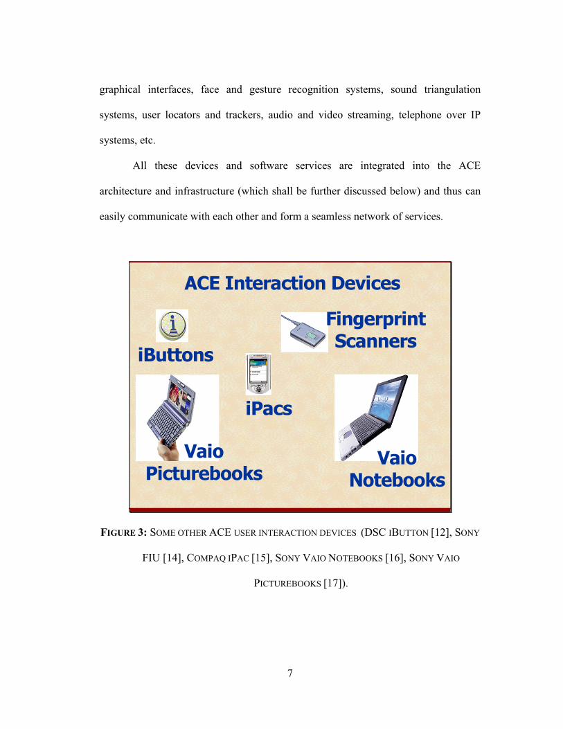
FIGURE 3: SOME OTHER ACE USER INTERACTION DEVICES (DSC IBUTTON [12], SONY
FIU [14], COMPAQ IPAC [15], SONY VAIO NOTEBOOKS [16], SONY VAIO
PICTUREBOOKS [17]).
8
1.3 ACE User Workspaces
Another significant form of access that an ACE provides for its users is a user
workspace. An ACE user workspace is a virtual computational space/environment
that a user may utilize to run his/her applications and access the ACE network. This
virtual space is defined physically as the graphical space on a terminal or workstation
screen where a user’s file space can be accessed, applications and programs can be
executed, and computational power utilized.
A user may have more than one instance of a workspace defined for
him/herself. In each workspace the user may run different programs while accessing
the same user file space.
In an ACE, a user may identify him/herself via an ACE identification device
in order to have his/her active workspace brought up on demand independent of
where the user is within the environment. Through his/her active workspace, the user
may bring up necessary files and run desired applications. Then, upon leaving or
logging off from a certain access location within an ACE, the workspace and its
current state are maintained. The user can then pick up where he/she left off at
another access point at a later time.
In a sense, a workspace is a virtual version of a user’s personal desktop
computer. The difference is that it has no physical dimensions. Therefore it may be
taken immediately to an access location where the user is and utilized on demand.
9
Chapter 2
ACE Service Daemon Infrastructure
As mentioned before, an ACE service can be any capability provided by ACE
whether this be data processing, data input, data storage, data transmission, device
control, network access, etc. In order to provide ACE users with a wide range of
distributed services and as part of the ACE requirements of modularity and flexibility,
it became obvious that ACE in itself would not be a single all knowing omnipotent
computational entity that controlled all sub-environments within a single ACE. In
fact, the concept of ACE required much the opposite style of computing where small,
independent, and distributed systems work together to endow ACE with its unique
capabilities. These simple systems can then come together like building blocks or
lego pieces to provide more complex functionalities, output, and/or behavior.
This reasoning led to the design of a basic ACE service daemon that is
responsible for performing a single, unique, and well defined function within the
ACE infrastructure. Thus, different and specialized daemons comprise the building
blocks of the ACE world. These are the independent pieces that work together to
provide a variety of more complex services/capabilities within ACE.
These unique services/daemons act as independent entities with unique
capabilities and can serve as both consumers and producers of services to any other

10
service. They must communicate with each other in a common all encompassing
language that can be easily decomposed and interpreted for issuing commands and
transmitting data. The diagram below depicts this concept.
Daemon
Daemon
Daemon
Daemon
Daemon
Database Storage & Retrieval
Device Output
Device Control
Processing / Conversion
Device Input
FIGURE 4: HOW ACE SERVICE DAEMONS INTERACT TO PROVIDE COMPLEX
CAPABILITIES AND COMPUTATION.
2.1 The ACE Service Daemon
Each service and/or device within an ACE is controlled directly by a unique
instance of an ACE service daemon. This daemon is responsible for being an
intermediary between the service/device control platform and the client wishing to

11
utilize the service/device. Note here that when a reference is made to a “client”
within an ACE that may refer to any kind of entity attempting to communicate and/or
request services from an ACE daemon. Such an entity may be a simple client
program or yet another ACE service daemon.
The daemon provides a structure for encrypted and certified socket
communications, service registration, and lease renewal (all of which shall be
discussed later). With this framework in place, implementing a service daemon and
along with all its necessary functions and command language semantic definitions
(based on an ACE command language - explained later) becomes a simple, standard,
and modular task. As services are implemented these can then be made to talk to one
another and provide services to one another. Thus building a complex system of
ACE services becomes a matter of simply defining functions and proper interface
commands between such services.
Each ACE daemon runs on its own thread of execution and thus is an
independent entity and may be run on separate machines spread throughout an ACE
network. Furthermore, each machine/computing system in an ACE may have one or
more ACE service daemons running within it, each providing a specific service.
2.1.1 Daemon Design
12
The statement made earlier about each daemon running on its own thread of
execution is true to a certain extent. It is true in that each daemon becomes a single
and independent entity as far as executing code and providing services.
In fact, each daemon consists of four threads that continuously run to endow
the ACE service daemon with its communication and service rendering capabilities.
These threads are the main thread, the command thread, the data thread, and the
control thread. The command thread is the only one created on a per connection
basis. Therefore a daemon may have more than one command thread running.
Each of these threads work independently of each other when communicating
with other daemons and when providing services. This is done in order to take
advantage of concurrency within multiprocessor machines running these daemons
and to separate communications from control and data streaming capabilities required
of an ACE daemon.
The main thread is responsible for initializing the daemon upon startup
(service registration, KeyNote authentication, etc) and managing the other threads.
The command thread handles the creation of socket communications between a client
and the service daemon itself and listens on the incoming connection for commands.
The data thread is responsible for handling any data stream operations over a UDP
channel. The control thread handles the execution of commands sent in through the
command thread and to service notifications if necessary.
All communications between these threads are carried out over message
queues that trigger actions as these messages are sent from one thread to another.

13
From this setup, ACE daemons become very independent and highly efficient
shells that serve as the basis for ACE services. As services are performed or
commands executed, more messages can be received, and others may be sent out, all
independent of each other and concurrently.
2.2 ACE Service Command Language
As previously stated, the services within ACE share a common control
language. This language is used by the ACE daemons to communicate both data and
service commands to each other.
The structure of this command language is based on the simple command and
arguments construction much like that seen in a regular Unix environment and
contains a few simple data types. Below is the syntactic definition of the ACE
command language.
<CMND> := <CMNDNAME><space>[<ARGLIST>];
<CMNDNAME> := <WORD>
<ARGLIST> := | <ARGUMENT> | <ARGUMENT><space><ARGLIST> |
<ARGUMENT>’,’<ARGLIST>
<ARGUMENT> := <ARGNAME>'='<ARGVALUE>
<ARGVALUE> := <INTEGER> | <FLOAT> | <WORD> | <STRING> |
<VECTOR> | <ARRAY>
14
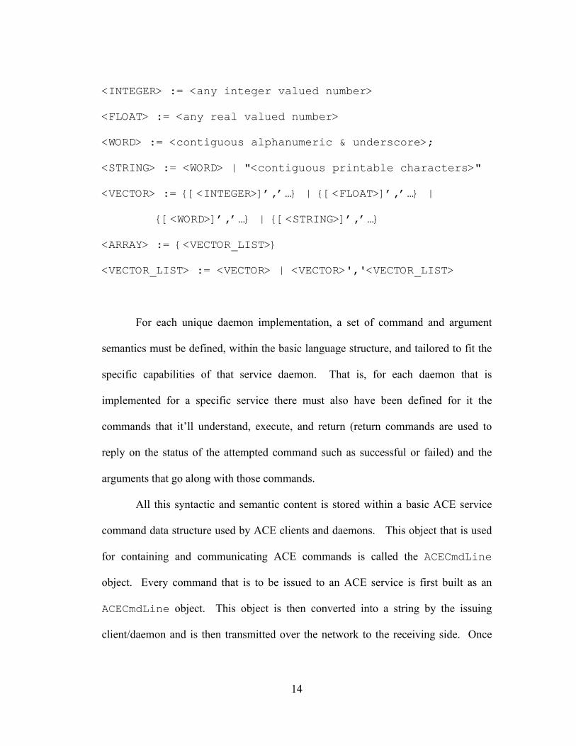
<INTEGER> := <any integer valued number>
<FLOAT> := <any real valued number>
<WORD> := <contiguous alphanumeric & underscore>;
<STRING> := <WORD> | "<contiguous printable characters>"
<VECTOR> := {[<INTEGER>]’,’…} | {[<FLOAT>]’,’…} |
{[<WORD>]’,’…} | {[<STRING>]’,’…}
<ARRAY> := {<VECTOR_LIST>}
<VECTOR_LIST> := <VECTOR> | <VECTOR>','<VECTOR_LIST>
For each unique daemon implementation, a set of command and argument
semantics must be defined, within the basic language structure, and tailored to fit the
specific capabilities of that service daemon. That is, for each daemon that is
implemented for a specific service there must also have been defined for it the
commands that it’ll understand, execute, and return (return commands are used to
reply on the status of the attempted command such as successful or failed) and the
arguments that go along with those commands.
All this syntactic and semantic content is stored within a basic ACE service
command data structure used by ACE clients and daemons. This object that is used
for containing and communicating ACE commands is called the ACECmdLine
object. Every command that is to be issued to an ACE service is first built as an
ACECmdLine object. This object is then converted into a string by the issuing
client/daemon and is then transmitted over the network to the receiving side. Once

15
received, this string is used to construct an exact copy of the ACECmdLine object by
means of the ACE Command Parser. This parser, built uniquely for the ACE project
service daemons, checks the incoming string for syntactic and semantic correctness
(against those parameters defined within the receiving daemon/service) and the new
ACECmdLine object is constructed. Once this is done, the recipient may access the
transmitted content of the command in order to perform its task. The diagram below
depicts this process.
Daemon DaemonCmdParserCmdLine Command String CmdLine
CmdLine converted into a string…
Command string transmitted over
network…
String converted into a CmdLine…
Command semantic definitions…
FIGURE 5: HOW ACE COMMANDS ARE BUILT, TRANSMITTED, AND INTERPRETED FOR
ACE DAEMON COMMUNICATIONS.
As can be seen, providing ACE with a unique and simple command language
allows for a very lightweight form of communication between services and clients. A

16
form of communication that is much more lightweight than utilizing something like
RMI.
2.3 ACE Service Daemon Hierarchy & Service Implementation
Another significant aspect of the ACE daemon infrastructure is its modularity
and ease of integration into the existing architecture.
The basic service daemon is primarily composed of three modules: the
daemon itself (implementation), the service’s command semantics, and the command
interface to that daemon. Each daemon command interface provides the means by
which users and other services access and command service daemons through the
network.
The service daemon itself is what executes the commands it receives,
operating on data, performing calculations, or serving as yet another interface to
something like a database or GUI.
The service semantics define the ACE commands and arguments to those
commands that are valid and understandable by the service daemon. These semantics
are used in the construction and parsing of service commands that are transmitted
from one daemon or client to another as was seen in the section 5.2 above.
Finally, the command interface is what provides users and client programs the
means by which to execute or request services from service daemons. These
17
interfaces are arranged in a hierarchical manner. In this way, child nodes inherit
methods, characteristics, and actions from the parent nodes. This inheritance is
achieved through the Java API utilized to create our daemon infrastructure. With this
structure, it is easy to develop different services and integrate them into the current
infrastructure. Additionally, with this type of inheritance structure, child nodes can
be developed to be like their parent nodes but with additional functionalities.
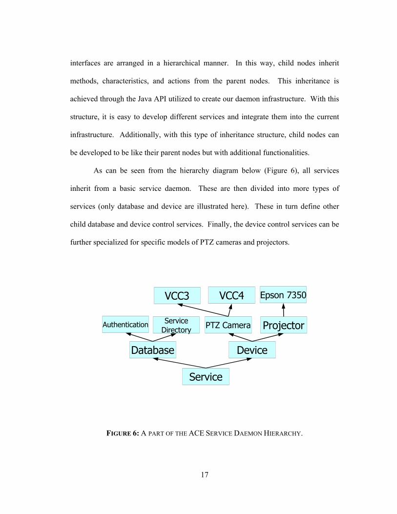
As can be seen from the hierarchy diagram below (Figure 6), all services
inherit from a basic service daemon. These are then divided into more types of
services (only database and device are illustrated here). These in turn define other
child database and device control services. Finally, the device control services can be
further specialized for specific models of PTZ cameras and projectors.
Service
Database Device
PTZ Camera
VCC3 VCC4
Projector
Epson 7350
ServiceDirectory
Authentication
FIGURE 6: A PART OF THE ACE SERVICE DAEMON HIERARCHY.

18
With this infrastructure, new services can be brought online quickly and
painlessly. Device and service specific portions of new services to be added are
isolated to prevent complete re-coding of service daemon specific framework. Also,
changes to the service designs and to their commands can be easily made and
propagated to all child services.
Another advantage of this modular daemon design is that the underlying
details of the service implementation are completely hidden from the client and its
programmer. All that needs to be known is the command interface to the service and
how to utilize it to obtain the capabilities needed.
2.4 Service Discovery – ACE Service Directory
If so many different and unique services can be made available within the
ACE infrastructure, how does one service find another? With services distributed
throughout the environment it becomes necessary to provide other services and
clients with the ability to quickly find and connect to desired daemons for specific
needs. ACE needs to provide services with this capability. A capability similar to a
DNS in which a central location or server can be queried for finding specific
machines within a network. ACE needs to supply services with the proper
information for finding other services within the ACE network.
Within this daemon infrastructure it became sensible to make such lookup and
discovery ability yet another service provided by an ACE daemon. This service is

19
called the ACE Service Directory – ASD. It serves as a central listing or directory of
services currently available and running within the ACE environment. Any and all
ACE services currently active automatically register themselves with the ASD service
(the location of which is known to all ACE daemons) so that other services and
clients know that it is active and available.
Registered services also automatically remove themselves from the ASD
registry upon shutdown by properly informing the ASD service of their removal.
Furthermore, if services become inactive due to programming errors or system
crashes, the ASD removes those services from its listing so that other services don’t
waste time and resources attempting to connect to a defunct ACE service. The simple
mechanism that has been implemented to do so is to create service leases within the
ASD. Upon registration with the ASD, each ACE service is given a lease time for
which they’ll be allowed to remain within the ASD listing. If a registered service
fails to renew its service lease with the ASD upon lease time expiration, this service
shall automatically be removed from the ASD. In order to remain in the ASD,
services must periodically issue service lease renewals with the ASD so that they may
remain registered within it. This mechanism accounts for the system failures
mentioned earlier whereby daemons that become inactive due to malfunction are
automatically removed from the ASD once their service lease expires.
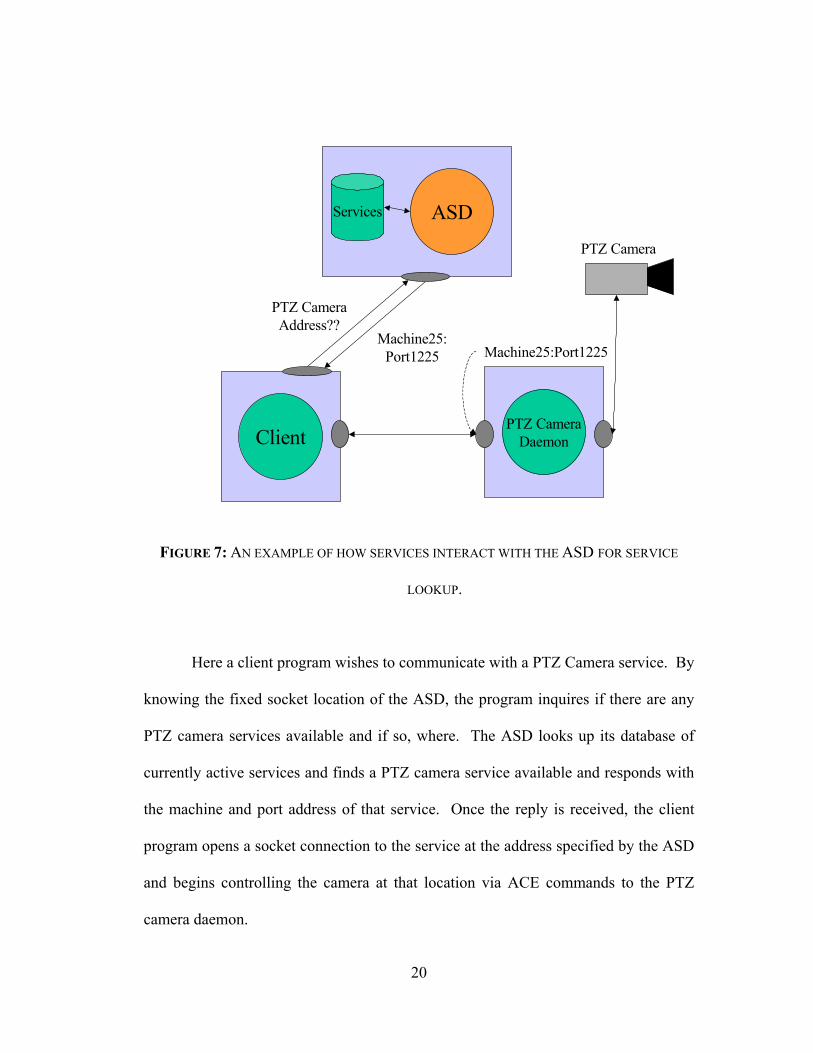
The next diagram (figure 7) demonstrates how the ASD is used.
20
Client
ASDServices
PTZ Camera Address??
PTZ CameraDaemon
Machine25:Port1225Machine25:
Port1225
PTZ Camera
FIGURE 7: AN EXAMPLE OF HOW SERVICES INTERACT WITH THE ASD FOR SERVICE
LOOKUP.
Here a client program wishes to communicate with a PTZ Camera service. By
knowing the fixed socket location of the ASD, the program inquires if there are any
PTZ camera services available and if so, where. The ASD looks up its database of
currently active services and finds a PTZ camera service available and responds with
the machine and port address of that service. Once the reply is received, the client
program opens a socket connection to the service at the address specified by the ASD
and begins controlling the camera at that location via ACE commands to the PTZ
camera daemon.

21
2.5 ACE Daemon Notifications
Another important component of an ACE service are notification commands.
The basic ACE daemon has incorporated within it the capability of notifying
interested parties (other services) of specific commands that have been issued and
executed.
This capability is what is called “ACE service notifications” and it is inherent
in all ACE daemons within the Service level (see section 5.3 above). Simply put, all
ACE daemons have notification commands semantically and syntactically defined for
them (i.e. within the ACE command language). These commands allow ACE
services to keep a running list of all other ACE commands that are being “listened”
for and all the ACE services that are to be notified when such commands are
executed.
For instance, let’s say that an ACE PTZ camera daemon is running within an
ACE conference room. Also, consider a basic requirement that whenever a new
person identifies him/herself at the door, that the camera point towards the door in
order to visualize the new user walking into the room.
In order for this to occur, a user identification daemon (that controls the
identification of users at specific ID devices) must notify the camera daemon that a
new user has been positively identified at the room door and is walking in. This
prompts the camera to turn towards the door and visualize the user.

22
The diagram below (Figure 8) depicts the details of this concept.
ServiceDaemon
Commands
Services to be Notified
ClientCommand Executed
Other Services Receive Notification
1
2
3
FIGURE 8: ACE SERVICE NOTIFICATIONS – AN INHERENT ASPECT/CAPABILITY OF ACE
SERVICE DAEMONS. SERVICES KEEP RUNNING LISTS OF WHICH SERVICES TO NOTIFY
WHEN CERTAIN COMMANDS HAVE BEEN EXECUTED BY THE DAEMON.
Above a client connects to a “Service Daemon” and issues an ACE command
(1). This daemon then looks up its list of commands to see if the command issued is
a command that prompts a notification and if so, which existing services need to be
notified for this command (2). Once the services that require a notification are looked
up by the daemon, the appropriate methods in those other services are invoked thus
23
effectively notifying these services that a specific command has been executed for the
service daemon at hand (3).
What exactly does it mean to receive a notification and have appropriate
methods invoked? Furthermore, how do services get added to the notification list to
begin with? When a service deems it necessary to be notified of a specific command
(call this the notified service) within some other service (call this the notifying
service), they issue an “addNotification” command to the notifying service either at
startup or later. This effectively adds the method name of the command interface
object (as seen in section 5.3 above) of the notified service to the list of services to
notify. Once a command is executed within the notifying service, all appropriate
command interfaces of services to be notified are referenced and the listed interface
methods are invoked on those services. This is what it means to receive a
notification.
This capability is very useful for ACE services in that these can now react to
changes in the environment and appropriately respond to user actions and adapt to
environment activity, crashes, and conflicts simply by notifying each other of such
changes.
2.6 Daemon Startup
Before each unique ACE daemon may start performing the service it was
intended to provide, it must go through a set of simple yet necessary initialization

24
steps within ACE to establish itself with its surroundings, register itself, and record its
existence.
UnixBootInit
ACEService
“foo”ASD
RoomDatabase
NetLogger
Host name “bar”
Host “bar” in Room “hawk”listening on port 1234
Room name “hawk”
Register: Service Name = “foo”Host = “bar”Port = “1234”Room = “hawk”Class = “ACEService”
Service “foo” Started!
2
3
5
ACEService
Service “foo”Start Notifications
Room: hawk
Host: bar
Launch14
FIGURE 9: A STEP-BY-STEP PROCESS THAT ALL ACE DAEMONS GO THROUGH TO
INITIALIZE THEMSELVES INTO AN ACE.
Consider the diagram above. Upon booting, the Unix machine “bar”
automatically launches the ACE service “foo” (1). The first immediate step the
service “foo” takes after initializing itself and its socket connection on port 1234 is to
contact the ACE Room Database service (discussed later) in order to establish its
location and surroundings and to place itself in the room database as one of the
available services in room “hawk” (2). Next, the service contacts the ASD on a
known socket and registers its information there so that other services in ACE are
able to find it (3). This registration may trigger notifications to other ACE services (if
any are awaiting notifications on it) that this new service “foo” is now running and

25
available (4). Finally, “foo” contacts the net logging service to register for historical
purposes that the service “foo” has started on host “bar” (5).
Once these steps are complete, the service can now begin performing the
actions it was programmed to do.

26
Chapter 3
ACE Security and Authentication
In this section, ACE security measures shall be discussed. These are
necessary to make ACE a network where only valid users with proper permissions
may run applications, access files, and transmit information in a secure fashion.
3.1 ACE Communications
As with any network environment, the communication framework must
provide a means of relaying information from point A to point B in a secure manner.
The security mechanism that has been incorporated into the ACE service
infrastructure in order to make sure that the communication between services and
clients is secure from eavesdroppers and unauthorized entities is the use of SSL
All ACE communications from one service to another is encrypted using SSL
(Secure Socket Layer) encryption. All the service commands using the ACE
command language and all data transferred between ACE services are encrypted in
this fashion at the socket level.

27
3.2 ACE Service Access and Authentication
Within an ACE network ACE users must be given access to underlying
network and also be registered with ACE in order to access and utilize ACE services.
In order to be properly identified within an ACE the user must first access an ACE
user identification device such as a fingerprint scanner, an iButton reader, or a badge
reader. Once this is done and the user has been identified, he/she may access the
services within an ACE. Unfortunately, being a valid ACE user does not get a user
far if he/she doesn’t have valid permissions.
In ACE, both users and services are restricted in the use of other services and
what commands may be issued. For this purpose, the KeyNote trust management
system [8] has been integrated into the ACE service infrastructure. Both users and
services shall have credentials and assertions defined for what can and can’t be done
within an ACE. These credentials control what commands can be issued, what
services can be accessed, what connections can be made, for how long services can be
utilized, how much of computing resources may be consumed, etc.
Below is an example of how ACE services verify permissions for a simple
ACE service.

28
Client ACEService
CredentialsDB
AuthenticationDB
Service
Credentials
OK
1
2
3
4
5
6
KeyNote
7
FIGURE 10: A DEPICTION OF HOW THE ACE SERVICE INFRASTRUCTURE WORKS WITH
AN AUTHENTICATION DATABASE SERVICE TO STORE AND MANAGE KEYNOTE
CREDENTIALS AND ASSERTIONS IN ORDER TO VERIFY USER PERMISSIONS AND
SYSTEM ACCESS TO ACE SERVICES AND INFORMATION.
In this example, a client wishes to execute a command on an ACE service (1).
The ACE service recognizes that a command is about to be executed by a specific
client and goes on to request the available KeyNote credentials and assertions for this
command and for this specific client from the Authentication Database Service (2).
This service serves as an interface to the storage and access of credentials and
assertions to other ACE services wishing to verify client trust. The Authentication
DB service looks up the necessary information from the database (3) and returns the
requested information to the ACE service (4). The ACE service then forwards this
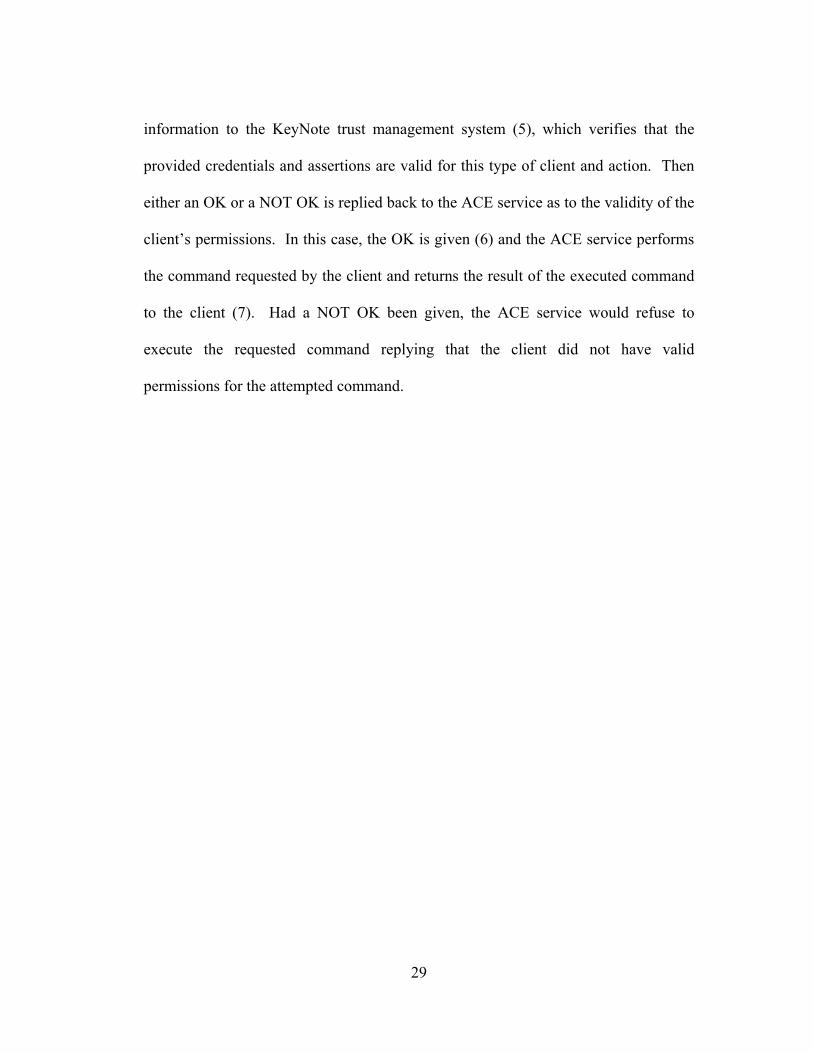
29
information to the KeyNote trust management system (5), which verifies that the
provided credentials and assertions are valid for this type of client and action. Then
either an OK or a NOT OK is replied back to the ACE service as to the validity of the
client’s permissions. In this case, the OK is given (6) and the ACE service performs
the command requested by the client and returns the result of the executed command
to the client (7). Had a NOT OK been given, the ACE service would refuse to
execute the requested command replying that the client did not have valid
permissions for the attempted command.

30
Chapter 4
Basic ACE Services
With the basic concept of ACE and the main daemon framework in place,
basic ACE services that interact with one another and provide a basis for other
higher-level services to be built upon can be constructed.
In this section, some of the basic services that have already been implemented
shall be presented. These services work together to provide ACE with the
accessibility, robustness, and distributiveness that are the main goals behind an
Ambient Computational Environment concept. These services work together to
provide the following ACE capabilities: virtual user workspaces, user registration,
identification, and authentication, service discovery, data conversion and distribution,
and network logging.
One of these services has already been seen – the ASD – since this was
necessary to understand the basic service discovery within the daemon infrastructure.
Now, some of the other services that provide the basis for the capabilities mentioned
above shall be examined.
31
4.1 HRM – Host Resource Monitor
The host resource monitor service provides computational and network
resource status on a single host (the same host this service runs on). The HRM
provides this information in one of two possible ways. It may supply this information
via notification commands (section 5.5 above) to services that request to be notified
or it may be queried for specific information by other services/clients.
Some of the information that is reported by the HRM to requesting services
include host CPU load, CPU speed (in bogomips), network traffic load, total and
available memory, and disk storage capabilities and size.
This service shall work in unison with other services to provide ACE with its
distributed and service robustness qualities (detailed in sections to come).
4.2 SRM – System Resource Monitor
The system resource monitor provides much the same kind of information as
the HRM service but is different in that it serves as the resource monitor for all the
machines running in an ACE environment. As described above, it communicates
with all HRMs below it in order to monitor all computing resources at a system wide
level thus allowing for uniform allocation and distribution of ACE system resources.
It also serves as the resource allocation interface between clients wishing to run
applications within ACE and single hosts executing these applications.
32
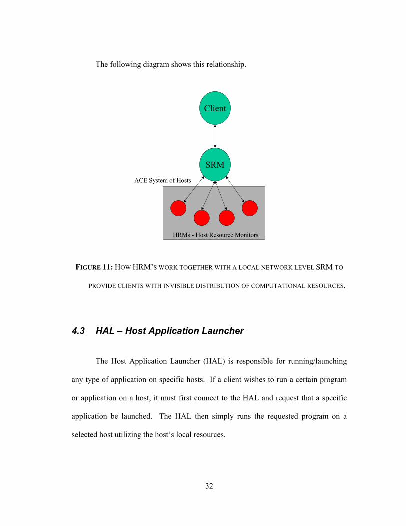
The following diagram shows this relationship.
SRM
Client
HRMs - Host Resource Monitors
ACE System of Hosts
FIGURE 11: HOW HRM’S WORK TOGETHER WITH A LOCAL NETWORK LEVEL SRM TO
PROVIDE CLIENTS WITH INVISIBLE DISTRIBUTION OF COMPUTATIONAL RESOURCES.
4.3 HAL – Host Application Launcher
The Host Application Launcher (HAL) is responsible for running/launching
any type of application on specific hosts. If a client wishes to run a certain program
or application on a host, it must first connect to the HAL and request that a specific
application be launched. The HAL then simply runs the requested program on a
selected host utilizing the host’s local resources.
33
4.4 SAL – System Application Launcher
The System Application Launcher or SAL is responsible for running a
specific program or application within an ACE local network. Much like an SRM
communicates with one or more HRMs below it to distribute computational
resources, the SAL delegates the responsibility of launching applications within an
ACE to its underlying HALs. Like an HRM, a HAL also resides locally on the host it
launches applications on.
If an ACE client wishes to run a specific application, it requests that that be
done to the SAL. The SAL then finds an appropriate HAL to launch the application
(randomly or by resource allocation by communicating with the SRM) and delegates
that responsibility to that chosen HAL. The HAL then runs the requested application
locally on its host.
4.5 WSS – Workspace Server
Another important ACE service is called the Workspace Server. This ACE
service is responsible for creating and removing user workspaces as these get created
and closed by users. It is also responsible for naming and keeping track of instances
of these workspaces that are created for specific users.
Remember from section 4 above, that a user workspace is a virtual area where
the user runs his/her programs and accesses his/her information. Also remember that

34
a user may have more than one user workspace running, thus it becomes necessary to
manage these workspaces for each individual ACE user.
An example of how this service works to provide users with virtual
workspaces shall be given in section 10 below where most of these services shall be
integrated into some typical ACE usage scenarios.
4.6 ACE ID Monitor Service
This service has the unique job of receiving user identification notifications
(refer to section 5.5 for daemon notifications) from ACE identification devices (such
as a fingerprint scanner service) and initiating the appropriate actions to account for a
positive or negative identification notification.
For instance, let’s say a user wants to have his/her workspace show up on the
screen of an access station after identifying him/herself via a fingerprint scanner. The
user presses his/her fingerprint to the scanner and is positively identified. The
identification device service sends a positive user identification notification to the ID
monitor. This in turn causes the ID monitor to call the workspace server to start up a
workspace viewer on the access station’s screen. If the user is not identified as a
valid user, the ID monitor can then call the appropriate services to deal with that
situation (e.g. if one wants to get extreme, call the FBI alerting service and notify
them of an intruder that must be arrested immediately).

35
4.7 AUD – ACE User Database Service
In order for any person to interact with an ACE he or she must be a valid ACE
user. What does this mean? It means that the person is not only a registered user
within the local computer network but also a user registered within ACE. In order to
register a user with ACE, the user must register basic information such as username,
password, full name, identification number (e.g. iButton #, fingerprint scan data, etc),
and public key (hence the reason why the user must be a valid user within the LAN)
with an ACE user management service. This service should manage users and their
information so that other services may or may not grant access to people wishing to
utilize ACE. Such a service must communicate with yet another service called the
ACE User Database.
This service is simply an ACE interface to a database of valid ACE users and
their pertinent information. The AUD takes insertion and selection query requests
from other authorized ACE services to lookup and modify the database of ACE users.
Access to this service and the user information is not limited to an ACE user manager
but to all other authorized ACE services that wish to find out some information about
a user or users they interact with.

36
ACE UserDatabase
Database
Client ClientClientClient
FIGURE 12: AN ACE USER DATABASE SERVES AS AN INTERFACE FOR SERVICES
WISHING TO STORE AND/OR ACCESS USER IDENTIFICATION INFORMATION FROM
THE DATABASE.
4.8 ACE FIU – Fingerprint Identification Unit
This service is a simple controller interface for the Sony fingerprint
identification unit model FIU-001/500 [13]. This service communicates directly to
the FIU, loading its tables of known fingerprints, querying it for identification of user
fingerprints, and serving as an interface to other ACE services wishing to identify
someone and/or receive identification notifications.

37
So, in other words, the FIU service has been implemented to identify ACE
users via their fingerprints serving as an interface to the Sony FIU device.
4.9 ACE IButton Reader Service
The IButton service is yet another user identification service that simply
interfaces to the IButton reader [12]. The IButton is a simple solid-state memory
device that stores a unique serial number (see figure 3 above). When associated with
a user, it may be used as an identification device. This ACE service serves to read
these numbers from the IButton reader, identify users based on known users and their
serial numbers stored in the AUD, and interface to other ACE services wishing to
identify someone and/or receive identification notifications.
4.10 ACE Authorization Database Service
This service, much like the AUD, is a database interface service that stores
user and client service authorization assertions. This service is utilized by ACE
services to lookup certificate assertions for users and other services attempting to
execute specific commands within ACE. These assertions are passed onto KeyNote,
which is used to determine if a proper assertion or chain of assertions are present thus
giving the client permission to perform specific actions.
38
This service was already introduced and exemplified as part of section 6.2
above.
4.11 ACE Room Database Service
In order for ACE services to be spatially aware of their surroundings and also
have some knowledge of where they reside within an ACE, their location information
(along with other data) is kept within an ACE Room Database service. This service is
responsible for storing and supplying services with information such as building
names, room names, names of services located within specific rooms, physical
location of these services in the room, physical dimensions of the room (for modeling
and logistical purposes), etc. For instance, for a user to control a camera daemon and
tell it to move to a specific position within the room, the camera needs to be spatially
aware of its environment. That is, it needs to know where it is located with respect to
locations and other objects within the room so that it may establish a 3D coordinate
system for referencing the room space. Furthermore, services need to know what
other services are in the room so that they may provide users with capabilities at
specific locations within an ACE.

39
4.12 ACE Converter Service
The ACE Converter service is basically what it states it is. It performs data
conversion from one format to another. For example, if video information was being
transferred from a camera in the ACE to a file managing system (that is, some video
information was being recorded onto disk) some kind of format conversion (or
compression) should be applied before this data can be stored. In order to do so, an
ACE converter is placed in between the video capture service and the file storage
service. It takes the raw video stream from the camera, converts it to a format such as
MPEG, and sends it to the file manager service for storage.
This service isn’t limited to this type of conversion. It is capable of
converting from one format to another from a set of known formats. The diagram of
this simple example is shown below.
VideoCaptureService
FileStorageService
Format Conversion
ACE Converter
Raw Video Transfer
MPEG Data Transfer

40
FIGURE 13: AN EXAMPLE OF HOW A VIDEO STREAM IS SENT THROUGH AN ACE
CONVERTER SERVICE FOR FORMAT CONVERSION BEFORE DATA STORAGE/USAGE.
4.13 ACE Distribution Service
Yet another low-level data transfer service available in ACE is the ACE
Distribution Service. This daemon takes in an input data stream and a set of known
destination services and forwards this data onto a set of one or more other services
that request that data.
Below is an example of a distribution daemon working to supply a set of ACE
services with a video stream from a video capture service.
VideoCaptureService
ACEService
ACEDistribution
Service
ACEService
ACEService
FIGURE 14: A DEPICTION OF AN ACE DISTRIBUTION SERVICE FORWARDS DATA FROM
ONE SOURCE TO ONE OR MORE ACE SERVICES.

41
4.14 ACE Network Logger Service
Last but not least is the ACE Network Logger. This service is used mainly for
security and debugging purposes within the ACE system. This service simply stores
service activity information within a set of logging files. This is used mainly to
record what kinds of activities are present within an ACE system and to serve as a
history so that, if necessary, system administrators can investigate them for security
holes or system bugs. An example of this would be an attempt of an invalid user to
log into the system. If an unknown user attempts to log into the system an invalid
identification error message along with pertinent details would be sent to the ACE
Network Logger for recording (via ACE notifications). If this persisted (more than
one attempt in different days) proper action could be taken to prevent the user for
tampering with the system.
4.15 A High-Level Service Example
Suppose a high-level audio system needs to be built. It is needed to connect
the audio signals of two remote sites/rooms and also include the output of a local
ACE service (as audio output) so that audio conferencing could be performed.
Furthermore, the conversation that is taking place needs to be recorded. A two-way
audio stream connection in between the two sites is to be constructed. It needs to be
42
free of feedback and allow other local ACE services to pick up on possible voice
commands to the local ACE by users in the rooms.
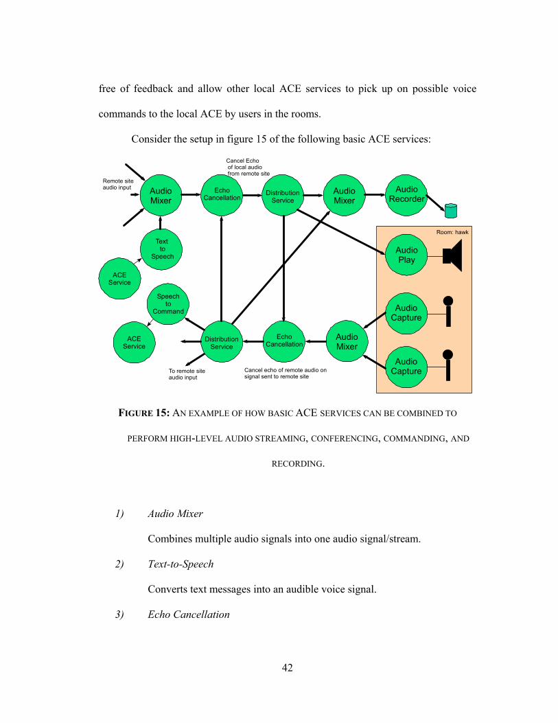
Consider the setup in figure 15 of the following basic ACE services:
AudioMixer
EchoCancellation
DistributionService
AudioMixer
AudioRecorder
AudioPlay
Speechto
Command
DistributionService
EchoCancellation
AudioMixer
AudioCapture
AudioCapture
Textto
Speech
Room: hawk
ACEService
ACEService
Cancel Echoof local audiofrom remote site
Cancel echo of remote audio onsignal sent to remote site
To remote siteaudio input
Remote siteaudio input
FIGURE 15: AN EXAMPLE OF HOW BASIC ACE SERVICES CAN BE COMBINED TO
PERFORM HIGH-LEVEL AUDIO STREAMING, CONFERENCING, COMMANDING, AND
RECORDING.
1) Audio Mixer
Combines multiple audio signals into one audio signal/stream.
2) Text-to-Speech
Converts text messages into an audible voice signal.
3) Echo Cancellation

43
Removes redundant audio signals (with an arbitrary amount of delay) from
an input audio signal.
4) Distribution Service
Distributes a given signal/stream to a set of known ACE services wishing
to receive the data.
5) Audio Recorder
Records on hard media a given input audio stream.
6) Audio Play
Plays an input audio signal on an output device such as a speaker.
7) Audio Capture
Captures an audio signal from a microphone and digitizes it so that it may
be streamed across the network.
8) Speech-to-Command
Analyses an input audio signal for specific voice commands and converts
them, if any, to a specific and well-known ACE service command
message.
From the diagram above, it is clearly visible how audio mixer services along
with distribution services can create a two-way audio stream allowing two-way
communications in between the sites.
Also, echo cancellation services may receive both audio signals from both
directions in order to correct for audio feedback.

44
An audio recording service connected to the distribution service allows the
entire conferencing conversation to be recorded for historical purposes.
Finally, text-to-speech and speech-to-command services can be placed at the
ends of the communications streams in order to provide ACE users with an
interactive interface to commanding and receiving responses from local active ACE
services.
45
Chapter 5
ACE User Applications
As has just been demonstrated, with the basic ACE services in place, other
high-level services can then be constructed to provide users and administrators with
easier access to the environment. These applications include user-friendly graphical
interfaces to devices and services, legacy applications integrated with ACE, general
purpose, communications, and data transfer applications, and administrative
applications used to register users, delegate authority, and control ACE specific data.
In section 3, an example of a graphical user interface for controlling devices
and services within ACE was demonstrated. Other legacy applications are also used
in ACE. These applications were integrated and/or modified to be part of ACE.
Some of these applications include VNC (Virtual Network Computing) from AT&T
labs [9] and Gnome O-Phone [10]. Finally, some other ACE built applications have
been included in the ACE system to utilize ACE resources and capabilities. These
include audio & video capture and camera and projector control services.
Before delving into these applications, how these applications can be run
within ACE (temporary, restart, and robust execution) must first be examined.
5.1 Temporary Applications

46
Within ACE any general-purpose application that is run on a user workspace
or on an ACE machine is considered a temporary application. This is mainly due to
the fact that such applications are not vital applications for the existence and
operation of an ACE.
Examples of such applications are word processors, Internet browsers, office
utilities, etc. These applications are allowed to crash and it is irrelevant to the ACE
system as a whole whether or not these applications are executed again.
5.2 Restart Applications
Restart applications are those that need to be running within ACE in order for
proper execution of ACE services but are allowed to crash or stop running for a small
interval of time and must then be restarted.
Examples of such applications can be a user’s default workspace, an ACE
camera control service, the network logger (even though some activity information is
lost), etc.
For this reason, these applications must be closely watched by other ACE
services in order to make sure they are up and running and be restarted in case of a
crash. Such a service has not yet been implemented but the ACE infrastructure
makes this possible and easy to do. Notifications can be utilized to alert such watcher
services of closed applications and can also work in conjunction with the ASD and
the WSS to make sure such restart applications are up and running.

47
This type of service is the next step in our current development of ACE to
ensure that applications that need to be up are always up and that they are restarted in
case of a crash.
5.3 Robust Applications
Robust ACE applications are those that are extremely vital to the proper
execution of ACE services and functioning of the system as a whole. Such
applications must not be allowed to crash, can be moved from one host to another
with minimal to no interruption of service, or have a backup redundant instance of the
application ready to take over in case it does stop running.
Such applications are ACE user management applications (that register and
identify users and distribute authorization), services such as the ASD and AUD, the
workspace server, etc. If any of these applications die for a long period of time the
consequences could be a partial to complete halt of ACE itself.
A basis for maintaining robustness of applications within ACE, as for restart
applications, has also not been fully implemented in our current version of ACE.
This endeavor is a complex one and must be developed closely with the work being
done within the persistent store. This is also in its initial stage and further
developments are still to come.

48
5.4 VNC & ACE User Workspaces
For a good part of this paper, the concept of user workspaces and how these
are managed and utilized were discussed but no thought was given to what actually
generates and controls a user’s workspace. This is where VNC (Virtual Network
Computing) from AT&T labs comes in [6].
This legacy application was taken, and its use slightly modified to fit the ACE
infrastructure. VNC is used to emulate user workspaces and redirect them to
appropriate ACE access points around the network.
VNC works in a client-server fashion. The VNC server as it is called, is
responsible for actually housing or running the user’s workspace, maintaining all state
information, and accepting input and output to the workspace when it is being
viewed/utilized by a user. The VNC client, or VNC viewer as it is called, is simply a
client program that runs remotely on a simple network access point and connects to
the VNC server. The server then redirects all I/O to that client/viewer thus allowing
the user to remotely see and command his/her workspace that is running at the server
location. Of course that in order for someone to access a workspace (i.e. run the
VNC viewer) he/she must provide the proper user password to the VNC server so that
proper access can be given. VNC also allows the user to have more than one running
workspace at the VNC server. This way a user may have multiple workspaces for
running different applications.

49
The diagram below shows a simple schematic of how VNC works by
redirecting I/O to remote machine viewers.
VNC Server
User Workspaces
VNC Viewer
VNC Viewer
FIGURE 16: HOW VNC WORKS TO PROVIDE VIRTUAL USER WORKSPACE ACCESS FROM
REMOTE ACCESS POINTS AROUND THE NETWORK WHILE RUNNING ON A SEPARATE
HOST MACHINE.
VNC usage was slightly modified for ACE. As seen before, the WSS is
responsible for managing user workspaces. It creates them, names them based on
whose workspace it is and where it is running, and deletes them when needed. It
must also verify user VNC passwords so that only valid users may see and access
their running workspaces. The normal execution of a VNC viewer requires that the
user input his/her password directly to VNC. Unfortunately, within ACE, the VNC

50
sessions are managed and controlled by the WSS. For this purpose, the VNC
password files were directly accessed and modified by the WSS when new
workspaces were created and when users accessed their workspaces from remote
access points. This guaranteed that the password verification by VNC was made
invisible to the normal ACE user. Simply by being a valid ACE user and properly
identifying him/herself with one of the ACE identification devices/services (e.g. FIU
unit), the user is allowed to access his/her workspaces via the WSS and VNC.
As was mentioned before, more insight shall be given to ACE workspaces and
how these are run with the examples in section 10 below.
5.5 O-Phone & ACE Communications
Another open source, legacy application incorporated into ACE is called the
O-Phone. This application enables full-duplex telephone communication over IP.
Thus allowing users to call each other and even external phones from their
workspaces. This frees up the user from having to be near a phone to make a call. If
a valid ACE user is near an access point, he/she can bring up a workspace and make a
phone call.
No major modifications were done to this application in order to incorporate it
in ACE. It was merely adapted to work properly with our local network and can thus
be run from any user workspace as a regular system application. No ACE GUI has

51
yet been developed for this application for ease with ACE usage. Creating an ACE
GUI for this type of application is next in current ACE developments.

52
Chapter 6
ACE Persistent Store
For ACE to be deemed the robust and long-lived user environment for both
data and running applications, a method of securely storing and retrieving data and
application state information and guaranteeing their persistence needs to exist. For
this reason it became necessary to develop persistent store structure and service for
ACE.
The initial conceptual framework entails the use of three completely
redundant and interconnected cluster of server systems.

53
ACEPersistent
StoreServer 1
ACEPersistent
StoreServer 3
ACEPersistent
StoreServer 2
Three, completely redundant storage systems guarantee safe and up to date
storage of information.
FIGURE 17: THE FIRST CONCEPTUAL FRAMEWORK OF HOW A CLUSTER OF THREE
PERSISTENT STORE SERVERS SHALL WORK TOGETHER TO PROVIDE REDUNDANT
AND ROBUST STORAGE OF ACE SERVICE AND APPLICATION STATE, PROVIDING THE
FOUNDATION FOR ACE ROBUST APPLICATIONS AND SERVICES.
The three storage systems above perform constant data synchronization in
order to ensure that the same exact data is stored within each of their individual
storage areas.
If for any reason, one or two of the servers fail or crash, ACE services may
still access the stored information within them. Furthermore, by having three separate
storage servers, it is possible to remove potential bottlenecks of many ACE services
attempting to access information on a single storage server at the same time.

54
ACE utilizes this redundant storage systems in order to safely maintain and
always have available all the user, service, and configuration information necessary to
make ACE a robust architecture on which services and applications can run and be
recovered.
Although this may seem to be a unique and completely different component of
the ACE architecture, it is simply another service within ACE. This service utilizes
the framework depicted above to provide robust and secure state information for other
services and clients within ACE so that if user workspaces, applications, and robust
services fail, they can quickly be recovered to their last known state. This type of
service utilizes a straightforward object-oriented namespace approach to storing
application and program state information and forms the basis for supporting restart
and robust applications as seen in sections 8.2 and 8.3 above.
Initially, development of this persistent store service framework was intended
to include M-VIA (Modular Virtual Interface Architecture) [11] as its network cluster
communications interface. This idea has currently been abandoned and other routes
are currently being investigated.
55
Chapter 7
ACE Scenarios
After touching on the ACE architecture and the main design components that
work together to make ACE a robust and interconnected framework of services, some
ACE scenarios can now be developed. These scenarios shall illustrate how the pieces
described above fit together to supply a coherent set of services and capabilities. All
of these scenarios have already been attempted and have successfully run in the
current version of ACE.
7.1 Scenario 1 – New User & User Workspace
John Doe is a new employee at ACECo. After getting settled in and getting to
know his new work environment he presents himself to the system administrator to
have a new ACE user account established for himself.
The administrator obtains from him all the pertinent information and creates a
new Unix user account for John. Then, he adds this new user as a new ACE user as
well. Utilizing a simple GUI, the administrator inserts John and his new account
information into the user database via the AUD service. His fingerprint is scanned
and added as well. As John is being added as a new user, the GUI also communicates
with the Workspace Server. The WSS verifies that this is a new user by checking that

56
the user information within the AUD is empty. This prompts the WSS to create a
new VNC server session (i.e. the user’s default workspace) for John. To do so, the
WSS requests from the SAL that a new VNC session for user John be started
somewhere. The System Application Launcher works in conjunction with the HAL,
SRM, and HRM to create a new default workspace for John. First, the SAL inquires
with the SRM to find out which machine in the ACE network is most suitable (has the
most free resources or is best for a given application) for running the VNC server
application. The SAL has this information with it from the regular communications it
holds with all the HRMs in the network to obtain host resource information. Once a
suitable host has been selected, the SAL requests from the HAL on the selected host
to launch a VNC server application as the default workspace for user John. Figure 18
below shows the connections between the services for a better understanding of these
steps.

57
FIGURE 18: A DIAGRAM OF HOW ALL ACE SERVICES ARE INTERCONNECTED TO
PROVIDE ACE USERS WITH IDENTIFICATION CAPABILITIES AND USER
WORKSPACES.
With this being done, John now has a default workspace constantly running
on the selected host.

58
7.2 Scenario 2 – User Identification
John is to give his presentation in the ACE conference room in 30 minutes. In
order to prepare for his presentation he goes to the conference room and identifies
himself at the podium computer by pressing his thumb to the fingerprint scanner next
to it. As soon as this is done, the user ID daemon, which constantly polls the FIU
(Fingerprint Scanning Unit) daemon, requests from the FIU that the user be verified.
In John’s case, he is a valid ACE user and is thus positively identified. This causes
the ACE User ID service to send out a notification that user ‘John Doe’ has been
identified at the ACE conference room to the ID Monitor service. The ID Monitor
service then updates John’s current location with the AUD. At this point John Doe
has been successfully identified and other services can now be invoked.
7.3 Scenario 3 – User Workspace
Once John Does has been successfully identified, the ID Monitor service is
responsible for communicating with the Workspace Server so that the user’s
workspace can be brought up to the user’s current access point.
The WSS invokes the SAL to start a VNC viewer session at John’s current
location (which was obtained from the ID Monitor) so that his default workspace may
be brought up. The SAL then invokes the HAL on John’s current host. This in turn
starts John’s VNC viewer application so that he may access his default user
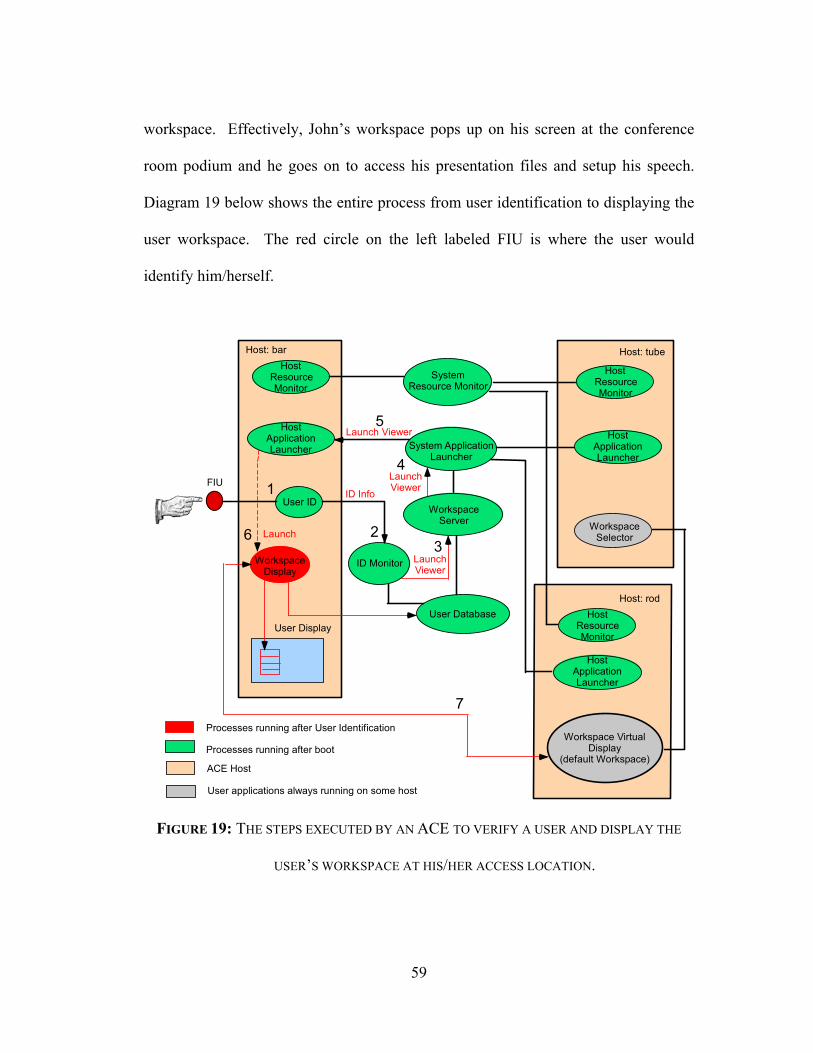
59
workspace. Effectively, John’s workspace pops up on his screen at the conference
room podium and he goes on to access his presentation files and setup his speech.
Diagram 19 below shows the entire process from user identification to displaying the
user workspace. The red circle on the left labeled FIU is where the user would
identify him/herself.
Host ResourceMonitor
Host ResourceMonitor
Host ApplicationLauncher
User ID
User Display
System ApplicationLauncher
System ResourceMonitor
ID Monitor
User Database
Workspace VirtualDisplay
(default Workspace)
FIU
ACE Host
User applications always running on some host
Processes running after boot
WorkspaceDisplay
LaunchViewer
LaunchViewer
Processes running after User Identification
Launch Viewer
ID Info
Launch
HostResourceMonitor
SystemResource Monitor
Host ResourceMonitor
HostResourceMonitor
HostApplicationLauncher Host Application
Launcher
HostApplicationLauncher
System ApplicationLauncher
WorkspaceServer
ID Monitor
User ID
HostResourceMonitor
Host ApplicationLauncher
HostApplicationLauncher
User Database
1
23
4
5
Host: bar Host: tube
Host: rod
6
7
Host ApplicationLauncher
WorkspaceSelector
FIGURE 19: THE STEPS EXECUTED BY AN ACE TO VERIFY A USER AND DISPLAY THE
USER’S WORKSPACE AT HIS/HER ACCESS LOCATION.

60
7.4 Scenario 4 – Multiple User Workspaces
Can a user have more than one workspace? The answer is yes. ACE users are
not limited to a single workspace (as has been mentioned earlier). The default
workspace is created for all users so that he/she may have at least one valid and
working workspace through which to access the network and its resources.
In creating new workspaces, the same basic ACE services are utilized to
launch, maintain, and display the running workspaces. The only significant
difference is that now users are presented with a workspace selector when a user
identifies him/herself (figure 19 above). This selector works in conjunction with the
WSS to find and display a workspace selected by the user.
Let’s say that John has been working on his presentation from a separate
workspace that is not his default workspace. So now, John has 2 valid running
workspaces. As soon as he identifies himself a small workspace selector GUI pops
up on the access point screen showing him a list of all workspaces running and
available. He selects the secondary workspace he owns and that causes the WSS to
attempt to launch the viewer of this workspace. It communicates with the SAL to do
so.
Soon enough, John’s secondary workspace is up and visible on the podium
access point and John continues to setup his presentation.

61
7.5 Scenario 5 – ACE Services & Devices
One last thing needs to be done before John can get his presentation ready to
go. He must turn on the projector and set the camera to point towards the podium.
Using his workspace, he starts the ACE device GUI. This GUI communicates with
the ACE Room Database service to find out what devices are present within the
room, where they are, and what current settings they have.
John selects the projector from a graphical representation of these devices.
This pops up another screen that shows the different controls that can be set for the
projector. He uses it to turn the projector on and to output the workspace to the
screen. This effectively causes the GUI program to communicate with the projector
daemon and send appropriate messages to execute John’s commands. Then, he
selects the camera output to stream to the projector as a picture in picture output.
Finally, he selects the camera and uses it to control the camera and pan, tilt, and zoom
it towards the podium.
All of these commands performed by John are fundamentally simple daemon-
to-daemon communications that are used to execute actions. Client and daemons
automatically find each other via the ASD and communicate with each other to obtain
and supply the proper information to perform a given task. The next stage in
development for ACE is to have all the above described commands be given by voice
and gestures.
John is now ready to give his presentation.
62
Chapter 8
Related Work
As was previously stated, the work being done here is one among many other
research projects currently being developed to create the next generation of widely
accessible and robust Internet applications and services. Next, a brief analysis is
made on the main aspects of some of these other projects in order to gain insight into
their principal differences so that possible improvements can be included in future
ACE developments.
The projects analyzed here have been chosen due to their similarity to ACE,
how complimentary their work is to that developed for ACE, and how insightful they
are to future ACE solutions.
8.1 UC Berkeley – Ninja Project
At the Computer Science department at UC Berkeley, important work has
been done in the area of next generation Internet based applications and devices. This
work is called the Ninja project [6].
The main focus of Ninja is that of the seamless integration of services and
devices that work together automatically to provide high-level services to its users
63
within a robust and long-lived cluster of workstations and accessed easily over the
Internet.
The Ninja architecture [18] consists primarily of four components: bases,
units, active proxies, and paths.
• Bases are clusters of workstations that serve as the computing basis for
service execution and state information storage.
• Units are the numerous different devices that are to be integrated into the
Ninja next generation Internet concept (e.g. PDA’s, cellular phone, pagers,
sensors, etc).
• Active Proxies are transformational elements or interfaces to the units
allowing them to be integrated with the Ninja service architecture.
• Paths are abstractions to the concept of composing more complex services
from a set of interconnected lower-level services, thus creating a conduit
or path through which data can be streamed through from service to
service, providing clients with unique and complex capabilities.
Ninja is very similar to ACE in many aspects. Like ACE, Ninja focuses on
the concept of easily accessible and reliable network of services (whether those be
applications or devices). Within ACE, the ASD is the service responsible for service
registration and is where services and clients go to find other services. In Ninja, that
similar service is called the SDS – Service Discovery Service. The bases in Ninja
provide services and applications with persistent state information in case of crashes

64
and system failures in much the same way that our persistent store architecture saves
the same state information via redundant server systems. Like ACE, the Ninja
architecture also facilitates for the integration of various heterogeneous devices
(“units”) and services within the network. Finally, the concept of creating modular
and simple services and composing them into “paths” [19] to generate high-level and
complex functionality is also the same within ACE.
Ninja on the other hand has some differences that are worthwhile examining.
First, Ninja’s active proxies are unique interfaces to user devices called units.
These proxies effectively translate the information to and from these units so that
proper unit to service communication can take place. In the ACE world, such
translation is built in to the ACE service that is specifically built to control and
intermediate for unique devices. The currently implemented interfaces for the
devices in ACE are built in C and utilize a Java wrapper that allows JNI calls to
service methods. Effectively, ACE devices are fully integrated ACE services. At the
service level, no distinction is made between software-driven and device rendered
ACE services.
Another main difference found is that in Ninja, service communication is done
primarily via object serialization and RMI. As was previously discussed, ACE
utilizes a unique ACE language constructed for ACE services and a language parser
to interpret messages sent from one service to another. This approach makes ACE
communications much more lightweight than that of Ninja’s bytecode transmissions,
which may be large depending on the service being rendered.

65
As previously stated, Ninja’s bases are clusters of workstations that are
utilized for computation and storage. Unlike ACE, Ninja groups these bases together
and all services execute on these clusters and communicate to devices via the Internet
or local area network. ACE, on the other hand, attempts to distribute its computing
power. Regular workstations spread throughout the environment may execute ACE
services. This not only reduces network traffic to local devices (devices that are
physically close to the workstation providing the service) but also makes response
times to these local services much more efficient.
Finally, Ninja attempts to fully automate the construction of high-level
services via their path concept and the use of XML descriptors accessed via the SDS
and XSet services [19]. This idea of Automatic Path Creation (or APC for short) has
no equivalent within ACE. Current developments in ACE call upon programmers to
hard code what services to look for when specific complex capabilities are needed. In
ACE, services cannot do that for themselves. They can of course connect to each
other and work together to provide complex services, but currently they cannot
determine on their own what services are needed to provide specific high-level
functions.
Ninja has come a long way in developing an infrastructure for ubiquitous
computing and further examination into their work may prove very useful for
improvements in the ACE architecture.
66
8.2 MIT – Oxygen Project
Another significant project developed at the Laboratory of Computer Science
and the Artificial Intelligence Laboratory at MIT is project Oxygen. This
multimillion-dollar project aims at adapting computers to the human world making it
easy for humans to interact with computers by visual cues and voice commands.
Oxygen attempts to make access to computational power pervasive and natural to
anyone. Furthermore, they envision making computers intelligent enough to interpret
and adapt to the needs of human users. Oxygen enables people “to do more by doing
less.” [20].
Oxygen’s goals are to create an environment where computing is pervasive
(found everywhere), embedded (sensing and affecting our world), nomadic (where
users and computation are free to move about), and eternal (always present, never
shutting down nor rebooting).
The main framework of Oxygen is built upon the notion of three important
components. The handheld H21 computers, the built in wall computers E21s (or
enviro21s as they are called), and the active and self adapting network N21 that
interconnects these computational units [7][21].
The H21s, or Handy 21s, are all-encompassing handheld devices that can
change from a wireless Internet connection to a pager, to an AM/FM radio, to a
walkie-talkie, TV, cellular phone, etc. It also contains a display, camera, IR
connector and radio antenna. It is low power, low bandwidth, with limited

67
computational capabilities, and mostly software driven. The H21s are the universal
interfaces of users to the Oxygen world.
The E21s are computers built into the rooms and environments that provide
users with access to higher computational power and bandwidth. These E21s can
communicate with the H21s for remote access and may directly control devices such
as phones, faxes, sensors, cameras, and microphones.
Finally, the decentralized networks called N21s provide adaptive network
topologies that react to changes in the network, in the devices connected to them, and
to changing conditions such as congestion, errors, and varied traffic. They also allow
for automatic resource and location discovery without manual system administration
and do all of the above in a secure and authenticated fashion. Although not explicitly
detailed, it is likely that an Active Networks approach may be taken for this purpose.
Oxygen envisions a world where web bots, computer secretaries, and task
automation in conjunction with a state-of-the-art speech recognition system allows
users to naturally converse with computers and obtain what they need from them. By
saying things like “Turn up the heat every morning at 7am” or “Find me the
presentation Maggie gave me two days ago” computers shall understand the
commands, interpret them, and make inferences based on users’ preferences and
histories to obtain exactly what they asked for. Again, the end goal: “doing more by
doing less.”
Oxygen’s basic conceptual framework is very different from that of ACE.
Much of Oxygen’s foundation is heavily based on the N21s and their adaptive and

68
automatic nature and on the H21s and E21s flexibility and computational power.
They centralize this power to these two units and rely on the N21 network to be
intelligent enough to efficiently interconnect them and adapt to changes in the
environment.
ACE is not limited to only a couple of devices and does not attempt to make
an all-encompassing handheld. Rather, ACE attempts to base computational power to
heterogeneous systems distributed throughout the network. It also maintains the
responsibility of supplying services, adapting to changes, and doing so in a secure
manner to service daemons running on these machines. Oxygen depends on the
versatility and power of the H21s and E21s to provide any and all services and that of
the N21s to provide them with adaptive and ubiquitous access to these services. This
is not to say that Oxygen’s approach is wrong, on the contrary, it is a novel and
unique approach but their sole dependency on the H21s and E21s may become
limiting in the future. On the other hand, the development of a self-organizing and
intelligent network that creates collaborative regions among Oxygen users, although a
complex task, may prove to be a very useful and powerful foundation.
8.3 IBM Corporation – WebSphere
Within the past few years, IBM Corporation has been working on a new way
to facilitate the integration of home and business devices to the Internet. At IBM’s
Pervasive Advanced Technology Laboratory in Austin, Texas, researchers have

69
created a complete working prototype of the future home, kitchen, and automobile.
They have created an environment where all devices within it are directly connected
to the Internet and all have their own unique URLs. Users can locally or remotely
control these devices by simply logging onto the Internet [22].
Behind all of this is IBM’s WebSphere Everyplace Server. This server is an
integrated software platform providing applications and devices with integration,
connectivity to the Internet, and with a realm of services ranging from security and
authentication, device and subscriber management, content transformation, and data
synchronization to messaging systems [23]. This platform aims at simplifying
connectivity and large-scale device integration for current enterprises and service and
content providers.
It also allows authenticated web-enabled applications and devices to connect
to it via third-party or their own wireless gateway and utilize their services. This is a
Java based software platform and utilizes HTTP as its main connectivity protocol to
third-party gateways and wireless devices. Authentication is also carried out over
HTTP [24].
The basic network and communications framework of this project greatly
differs from that of ACE in its communications protocol and in that it attempts to
centralize device and applications integration and control to a main server or cluster
of servers that oversee all connections and users. Although this approach has proven
scalable through simulations [23] it may not be appropriate or viable for small-scale
purposes and environments. Furthermore, it lends itself to dependency on IBM

70
developers to extend its capabilities and include new services, making it impossible
for outside developers to create and integrate their own services. Also, this
framework does not manage device state information and expects the outside devices
and applications to handle their own state persistence.
Although this platform is an attempt at simple and large-scale integration of
Internet applications and devices and has a very different architecture, it is rich in
ideas and possibilities as far as services and potential applications of pervasive
computing are concerned. New developments within IBM’s WebSphere may become
very useful to future ACE developments and in extending its concepts.
8.4 Sun Microsystems – Jini
Another important development in this area was made by Sun Microsystems –
the Jini technology [25]. The main idea behind Jini is that its very simple framework
gives developers the freedom to create network-enabled services that may be
implemented in either software or hardware.
Jini is built upon Sun’s own Java interface and utilizes Java’s RMI (Remote
Method Invocation) and object serialization for clients to utilize services over the
network.
The basic Jini framework consists of network services, clients, and a lookup
service for finding other services on the network [26][27]. A multicast mechanism is
used to find the lookup service either for service registration or for other service

71
lookups. Network services wishing to be registered with the lookup service or “join”
the network of services must first find the lookup service via a multicast message and
register their interface attributes (what methods they can execute) with it. Clients
wishing to “discover” services also utilize a multicast mechanism to find the lookup
service and then query the lookup service for specific well-known service method
interface attributes. Once a service is found, a service proxy is passed onto the client
and the service is rendered directly to the client via RMI.
Jini also allows for service leasing within the lookup service and for an event
driven model allowing other services to be notified of specific events in the network.
Furthermore, Jini utilizes its own implementation of ACL’s and principals for trust
management within the network.
At first glance Jini contains many elements that are similar to those developed
within ACE – a lookup service, service discovery, service lease times, event
notifications, freedom of service development for software and hardware
applications, a service/client duality allowing services to become clients and utilize
other services, and the ability to utilize non-Java services via Java interfaces.
Although the above-mentioned characteristics are very advantageous to the
development of ACE, the decision was made not to use Jini within the ACE
architecture due to some of its non-desirable traits. Jini is still at its very early stages
and desirable devices and software interfaces for basic services have not yet been
released. Also, as Jini is licensed under the Sun Community Source License [28] that
poses as an obstacle for future code modification and redistribution for developments

72
such as potential mobile sockets currently being investigated for ACE. Finally, Jini
utilizes its own trust management implementation thus the utilization of the KeyNote
Trust Management system (which is very desirable for our applications) becomes
difficult or impractical.
Therefore, although Jini provides a very flexible and simple architecture for
ACE-like capabilities, it is still very new and also restrictive as far as security,
modification, and redistribution are concerned.

73
Chapter 9
Improvements & Future Work
The ACE project was started early in the spring of 2000 and although much
development work has been done to lay its foundations – the main daemon
infrastructure, and the basic ACE framework services – much design and
implementation work remains to be done.
Currently, the main challenge for development of ACE deals with creating a
robust and reliable system of services that can detect and recover from failures and is
scalable to serve hundreds and even thousands of users. This task is composed of
many different research areas. First and foremost, a service structure must be created
to detect and handle system and service crashes, quickly identifying failures and re-
initializing restart and robust applications and services. Secondly, research and
development of mobile sockets must be integrated with the current ACE service
infrastructure to handle downed ACE services allowing clients to quickly resume
their tasks with other service instances and to ensure service mobility. Thirdly,
continued work must be done to implement and integrate a persistent store
mechanism within the service daemon framework to ensure that state information is
maintained for robust services and applications. Also, the authentication capabilities
of KeyNote’s credentials within ACE must be extended to allow for more flexible
authentication criteria (which is limited at its current implementation). Finally,

74
significant amount of testing must be done to ensure the scalability of the system and
that ACE can fulfill the concept of a long-lived system. Central services such as the
ASD, AUD, WSS, etc must be fully tested for large communication loads,
persistence, and extended execution time.
If ACE succeeds in becoming the long-lived, reliable, robust, secure, and
widely accessible system that it is envisioned to be, then further developments can be
made in the areas of speech recognition, natural language analysis, gesture and face
recognition, audio triangulation, personnel tracking, multi-modal user interaction,
multi-format data streaming, real-time written and spoken language translation, task
automation (e.g. properly executing the command “print this out to the nearest
printer”), and creation of intelligent devices and applications such as adaptive camera
systems (i.e. automatic control of image quality), automatic climate control systems,
lighting control systems, personal virtual administrative assistants, etc.
It may also be advantageous to further investigate and integrate some concepts
taken from other projects such as Ninja and WebSphere into ACE. Some of these
concepts include Ninjas’s Automatic Path Creation with XML and IBM’s user
interaction devices and modalities such as ACE enabled cars, coffee makers, digital
art, entertainment systems, etc.

75
Chapter 10
Contributions & Innovations
ACE, its architecture, and its implementation have been made possible by the
contributions of many professors, students, and staff alike. Many of the components
that have been here presented were created by individual and group efforts of the
ACE development team, including my own.
Additionally, ACE itself presents researchers and developers with some
unique and innovative design components that are important and worthwhile
considering.
10.1 ACE’s Innovations
The ACE architecture presents many advantages and qualities that make it a
flexible, robust, and lightweight system. It is also a system in which the development
of new applications and services are made easy and fast. Some of these qualities and
design approaches are unique within the world of the next generation Internet and
significant to point out.
Some of these unique qualities include:
• A modular service daemon structure, making the integration and development
of new and heterogeneous services and technologies simple for developers.

76
• An ACE service daemon hierarchy that makes the development and alteration
of service elements effortless. A service hierarchy unique within the realm of
pervasive computing.
• An ACE command language and its corresponding parser (developed
explicitly for ACE and geared towards service communications) that allow for
very lightweight service-to-service communications. A construct unseen in
any other pervasive computing project and with the potential of making ACE
a competitive architecture efficiency-wise.
• An architecture that aims at open source development unlike many similar
projects that have developed their own proprietary code and utilized licensed
and restricted applications. ACE has integrated a variety of open source
applications with its architecture and aims at open redistribution objectifying
unrestricted development and improvement of its architecture and services.
An approach that may prove advantageous for allowing ACE and its original
ideas to improve and percolate through to the Internet of the next generation.
These unique qualities make ACE a novel system and provides singular
contributions to the work currently being done in the area of pervasive computing.

77
10.2 Personal Contributions
The ACE effort includes some of my own personal work. Listed below are
some of my main contributions to the ACE effort along with references to pertinent
internal ACE documentation.
1. Assisted in the design of and completely documented the ACE command
language.
(Internal Documentation File Names: ACELanguageReqs.doc,
ACELanguageSpecs.doc, ACECommandObjectSpecs.doc)
2. Design, documentation, and implementation of the ACE command language
parser.
(Internal Documentation File Names: ACEParserDesign.doc,
ACEParserEnumTypesDesign.doc, ACEParserCmdArgExtentSpecs.doc,
ACEParserSpecifications.doc)
3. Design, documentation, and implementation of the ACE Service Directory.
(Internal Documentation File Names: ACEServiceDirectorySpecs.doc,
ACEServiceAttributesSpecs.doc, ACEServiceClassHierarchySpecs.doc,
ACEServiceDirectoryDatabaseDesign.doc,
ACEServiceDirectoryDesign.doc,)
4. Design, documentation, and implementation of the ACE User Database
service.

78
(Internal Documentation File Names:
ACEUserDatabaseServiceRequirements.doc,
ACEUserDatabaseDBDesign.doc, ACEUserDatabaseServiceDesign.doc,
ACEUserAttributesSpecs.doc,
ACEUserDatabaseServiceSpecifications.doc)
5. Development and documentation of a standardized script for regression
testing of ACE services.
(Internal Documentation File Names: ACECodeDebugRequirements.doc,
ACERegressionTestingRequirements.doc, ACEErrorConventionSpecs.doc,
ACETraceSpecifications.doc)
6. Working directly within the ACE architecture development team contributed
with ideas, suggestions, and solutions in brainstorming sessions as the ACE
architecture grew and took shape.
79
Chapter 11
Conclusions
In this paper many aspects of the ACE architecture have been examined.
These aspects included ACE users and how humans interact with the environment,
the basic daemon framework and its capabilities, security and authentication within
ACE, user applications and legacy systems incorporated into ACE, and the base ACE
services implemented and currently under development. Basic scenarios depicting
the interaction of users and ACE systems were covered and current developments by
other corporations and universities in the area have been discussed.
Clearly ACE has many unique advantages. Its modular service daemon
structure and hierarchy simplifies service development and allow for flexible higher-
level service construction. The daemon’s built in notifications capabilities allow for
desired event-driven models. The daemon’s multithreaded nature allows services and
the underlying system to take advantage of execution concurrency. Finally, the ACE
user workspaces approach is a good compromise between the well-known desktop
PC’s and the full virtual data and services integration of the future.
It is clear from the ACE architecture, its novel capabilities, its advantages, and
from the work done in other similar projects that ACE and its daemon framework not
only have potential to become the envisioned pervasive and robust system but to also
be a flexible, modular, and easily adaptable platform on which to develop new

80
services and capabilities. Moreover, it is also an architecture that allows developers
the freedom to expand its capabilities and applications in any imaginable way. ACE
has become a very worthwhile infrastructure on which to build. At its current state,
ACE begs continued exploration, experimentation, and improvement.

81
Bibliography
[1] IBM Corporation. Pervasive Computing Website.
http://www-3.ibm.com/pvc/index.shtml/.
[2] International Conference on Pervasive Computing. Pervasive 2002.
http://www.pervasive2002.org/.
[3] Brown, Eric S. MIT Technology Review. “Project Oxygen’s New Wind –
Q&A with Rodney Brooks and Victor Zue.” December 2001.
http://www.technologyreview.com/articles/4152.asp/.
[4] Anderson, David P. and Kubiatowicz, John. Scientific American Article.
“The Worldwide Computer.”
http://www.sciam.com/2002/0302issue/0302anderson.html/.
[5] Information Telecommunication Technology Center – University of Kansas.
Ambient Computational Environments Project home page.
http://www.ittc.ku.edu/~ace/.
[6] UC Berkeley Computer Science Division. Ninja Project home page.
http://ninja.cs.berkeley.edu/.
82
[7] MIT Laboratory of Computer Science; MIT Artificial Intelligence Laboratory.
Oxygen Project home page.
http://oxygen.lcs.mit.edu/.
[8] Matt Blaze, Joan Feigenbaum, John Ioannidis, and Angelos D. Keromytis.
“The KeyNote Trust-Management System, Version 2.” Request For Comments
(RFC) 2704, September 1999.
http://www.cis.upenn.edu/~keynote/Papers/rfc2704.txt/.
[9] AT&T Laboratories Cambridge. VNC – Virtual Network Computing home
page.
http://www.uk.research.att.com/vnc/.
[10] GNU Gnome. O-Phone (G-Phone) home page.
http://gphone.sourceforge.net/.
[11] National Energy Research Scientific Computing Center home page. “M-VIA:
A High Performance Modular VIA for Linux.”
http://www.nersc.gov/research/FTG/via/.

83
[12] Dallas Semiconductor Designs. iButton website.
http://www.ibutton.com/index.html/.
[13] Sony Corporation. FIU – Fingerprint Identification Unit model FIU-001/500
home page.
http://www.iosoftware.com/products/integration/fiu500/.
[14] Sony Corporation. FIU – Fingerprint Identification Unit model FIU-710
home page.
http://www.sony.co.jp/en/Products/puppy/.
[15] Compaq Corporation. iPAQ handhelds website.
http://athome.compaq.com/showroom/static/iPAQ/handheld
_jumppage.asp/.
[16] Sony Corporation. Vaio notebook series website.
http://www.sonystyle.com/vaio/grx/index.shtml/.
[17] Sony Corporation. Vaio picturebook notebook series website.
http://www.sonystyle.com/vaio/picturebook/index.shtml/.

84
[18] Steven D. Gribble, Matt Welsh, Rob von Behren, Eric A. Brewer, David
Culler, N. Borisov, S. Czerwinski, R. Gummadi, J. Hill, A. Joseph, R.H. Katz,
Z.M. Mao, S. Ross, and B. Zhao. The Ninja Architecture for Robust Internet-
Scale Systems and Services. Available at:
http://ninja.cs.berkeley.edu/pubs/pubs.html/.
[19] Sirish Chandrasekaran, Samuel Madden, and Mihut Ionescu. Ninja Paths: An
Architecture for Composing Services Over Wide Area Networks. Available at:
http://ninja.cs.berkeley.edu/pubs/pubs.html/.
[20] Dertouzos, Michael L. Scientific American article. “The Future of
Computing” 1999.
http://www.sciam.com/1999/0899issue/0899dertouzos.html
/.
[21] Hedberg, Sara Reese. IEEE Intelligent Systems magazine article. May-June
2000 issue. “Intelligencer – Ubiquitous Computing.”
http://www.computer.org/intelligent/ex2000/pdf/x3002.p
df/.
[22] IBM Corporation. York, Candice A. “IBM’s Advanced PvC Technology
Laboratory.”

85
http://www-
106.ibm.com/developerworks/wireless/library/wi-
pvc/?t=gr252/.
[23] IBM Corporation. Case-Hook, Lisa and Shaheen, Amal. “WebSphere
Everyplace Server, Service Provider Offering for Multiplatforms.” IBM
WebSphere whitepaper. September 2001. Available at:
http://www-
3.ibm.com/pvc/tech/pdf/WESSPO_20MM_User_white_paper.pd
f/.
[24] IBM Corporation. Nguyen, Chung. “Third-Party Gateway Plug-in Support
in the WebSphere Everyplace Server.” IBM WebSphere whitepaper. December
2001. Available at:
http://www-3.ibm.com/pvc/products/pdf/ThirdPartyGW-
Plugin.pdf/.
[25] Sun Microsystems. Jini Network Technology home page.
http://www.sun.com/jini/.
[26] Sun Microsystems. Jini Network Technology datasheet.

86
http://www.sun.com/jini/whitepapers/jini-
datasheet0601.pdf.
[27] Sun Microsystems. Jini Architecture Specification document. 2001
http://www.sun.com/jini/specs/jini1_2.pdf
[28] Sun Microsystems. Sun Community Source Licensing home page.
http://www.sun.com/software/communitysource/.