Embed Size (px)
Citation preview
The Amazing MFJ 269
Author Jack Tiley AD7FO ARRL Certified Emcomm and license class Instructor, Volunteer Examiner, EWA Technical Coordinator and President of the Inland Empire VHF Club
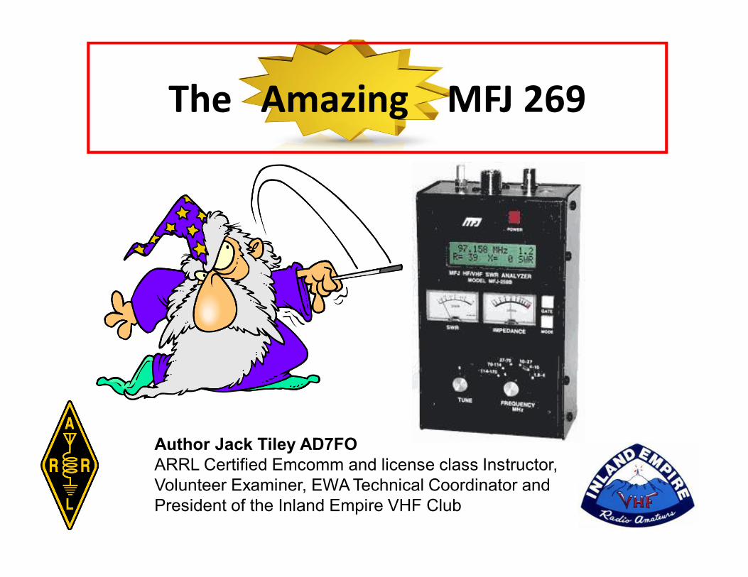
• Frequency• VSWR• Impedance• Impedance Phase Angle• Electrical line length• Feed line loss in dB• Inductance in µH• Capacitance in pF
What Can be Measured?• Resistance• Resonance• Return loss• SWR at Zo
• Use as RF signalsource
•Measurements at other than Zo = 50 Ω
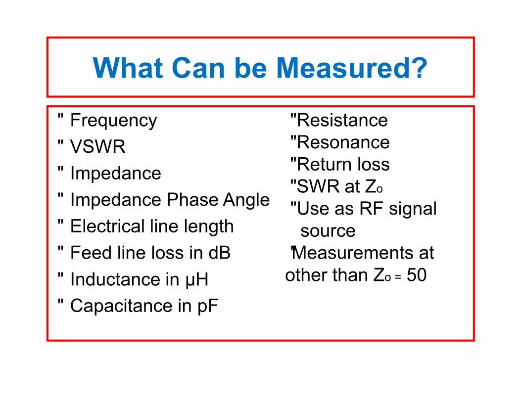
• Antennas – SWR, impedance, reactance, resistance, resonant frequency & bandwidth
• Antenna Tuners- SWR, bandwidth & frequency• Amplifiers – input & output matching networks
& traps• Coaxial Transmission Lines – SWR, Length,
velocity factor, loss & impedance• Filters – SWR, attenuation & Frequency• Matching or Tuning Stubs –SWR, approx. Q,
resonant Frequency, bandwidth & impedance
Typical Uses
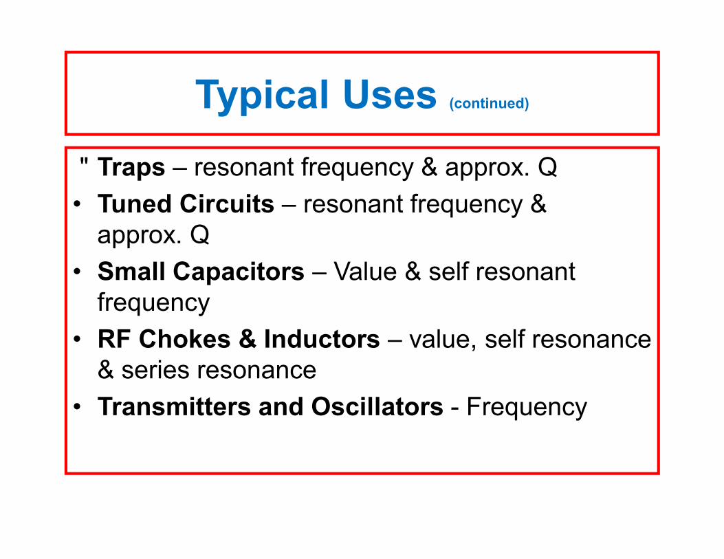
• Traps – resonant frequency & approx. Q• Tuned Circuits – resonant frequency &
approx. Q• Small Capacitors – Value & self resonant
frequency• RF Chokes & Inductors – value, self resonance
& series resonance• Transmitters and Oscillators - Frequency
Typical Uses (continued)
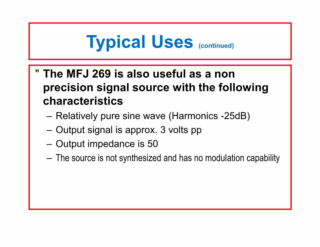
• The MFJ 269 is also useful as a non precision signal source with the following characteristics– Relatively pure sine wave (Harmonics -25dB)– Output signal is approx. 3 volts pp– Output impedance is 50Ω– The source is not synthesized and has no modulation capability
Typical Uses (continued)
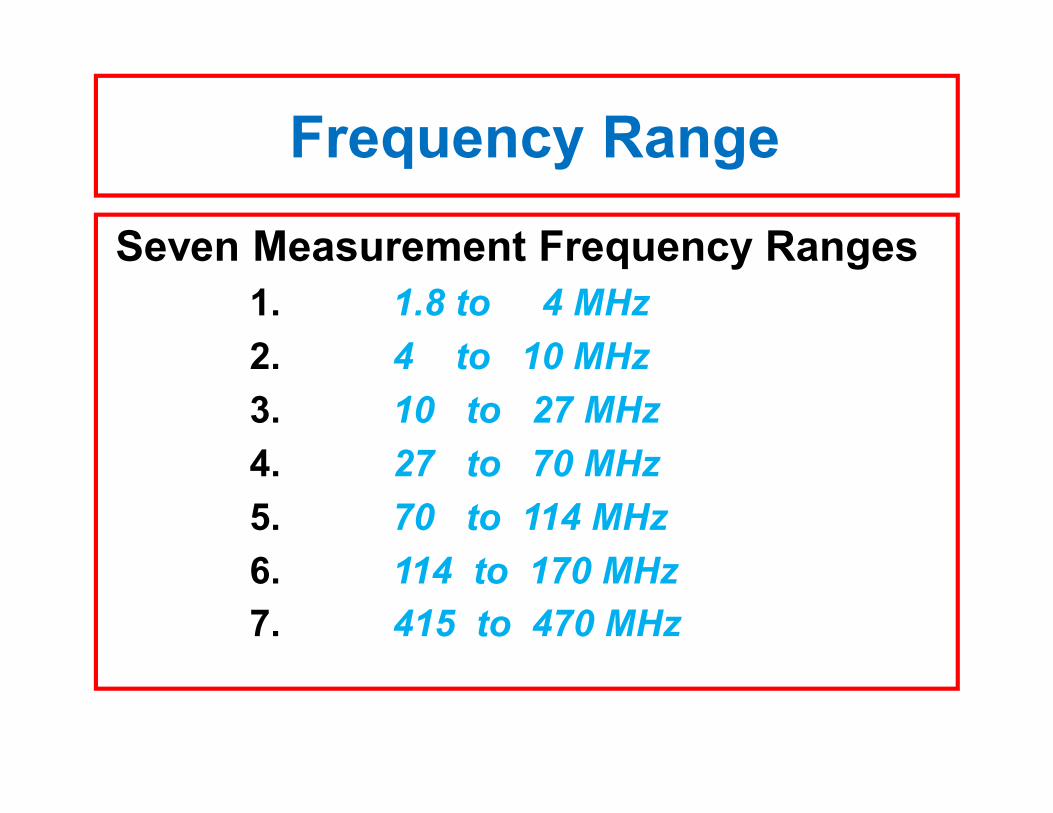
Frequency Range
Seven Measurement Frequency Ranges 1. 1.8 to 4 MHz2. 4 to 10 MHz3. 10 to 27 MHz 4. 27 to 70 MHz 5. 70 to 114 MHz 6. 114 to 170 MHz 7. 415 to 470 MHz
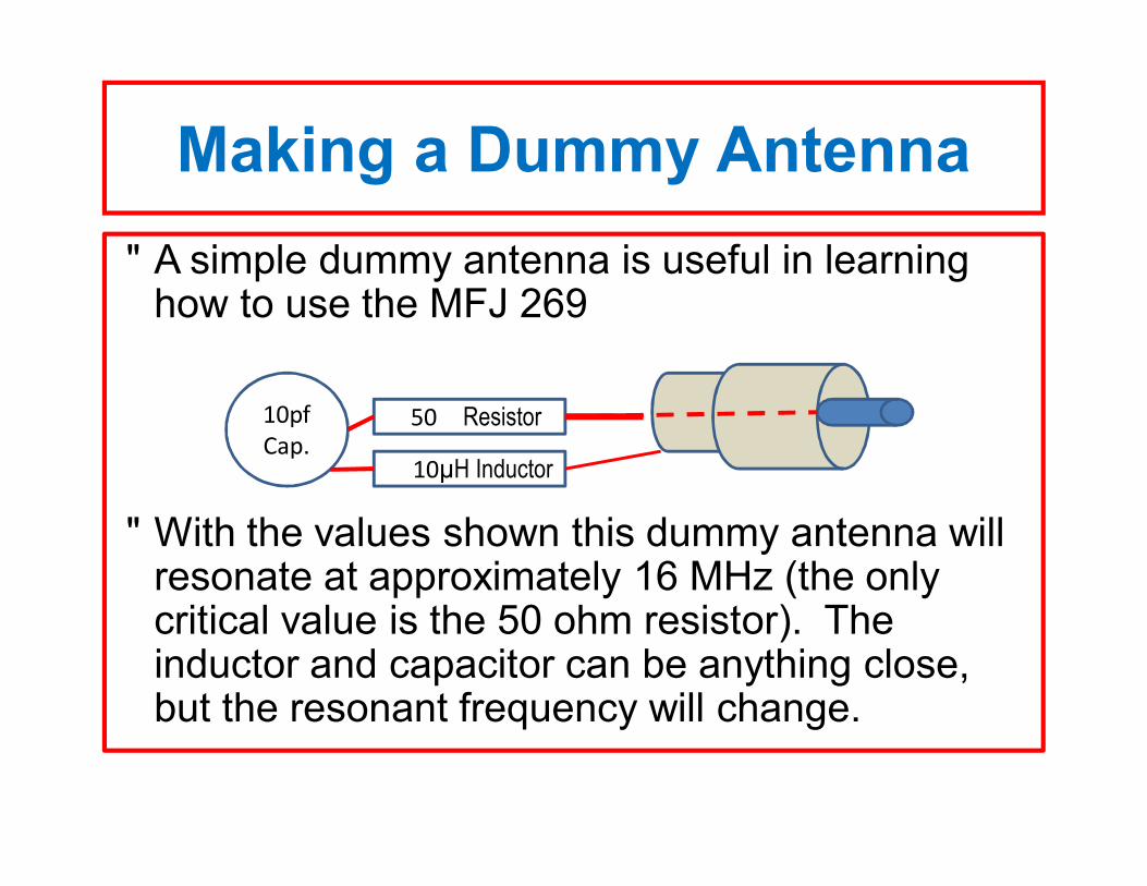
Making a Dummy Antenna• A simple dummy antenna is useful in learning
how to use the MFJ 269
• With the values shown this dummy antenna will resonate at approximately 16 MHz (the only critical value is the 50 ohm resistor). The inductor and capacitor can be anything close, but the resonant frequency will change.
550Ω Resistor
1010µH Inductor
10pfCap.
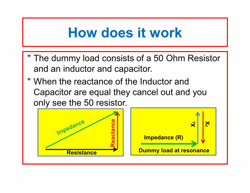
How does it work • The dummy load consists of a 50 Ohm Resistor
and an inductor and capacitor. • When the reactance of the Inductor and
Capacitor are equal they cancel out and you only see the 50 resistor.
Impedance (R)
XL
Xc
Dummy load at resonanceResistance
Rea
ctan
ce
• When connecting any cable or device be sure to discharge any static electricity before connecting it by shorting the center pin to the shield before connecting it to the MFJ 269
Caution to Prevent damage
• Do not apply any RF voltage or DC directly to the antenna connector.
• Be sure the UHF button is off (out) before turning the power on.
Caution to Prevent damage
Main Measurement ModesThere are five measurement modes available at turn on of the MFJ 269.
• MODE 1 – Measuring SWR – Impedance –Resistance – reactance.
• MODE 2 – Measuring coaxial cable loss.• MODE 3 - Measuring capacitance • MODE 4 – Measuring Inductance• MODE 5 – Measuring frequency
Measuring R & X (mode 1)
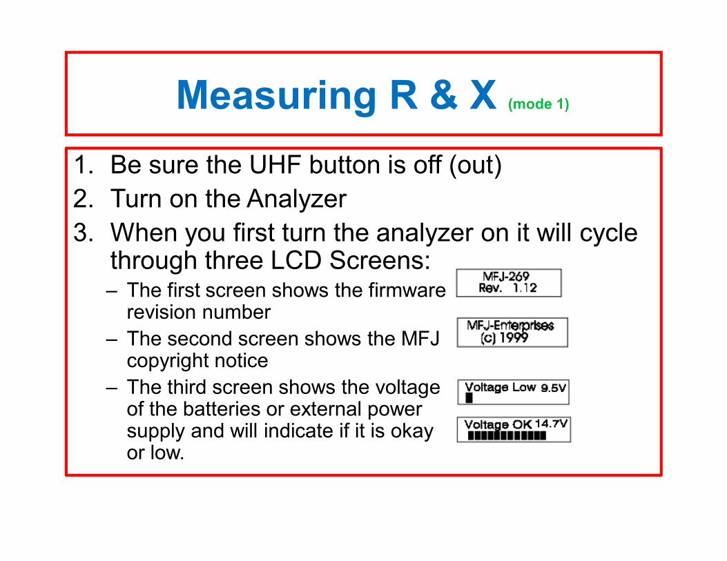
1. Be sure the UHF button is off (out)2. Turn on the Analyzer3. When you first turn the analyzer on it will cycle
through three LCD Screens:– The first screen shows the firmware
revision number– The second screen shows the MFJ
copyright notice– The third screen shows the voltage
of the batteries or external power supply and will indicate if it is okay or low.
Measuring R & X (mode1)(continued)
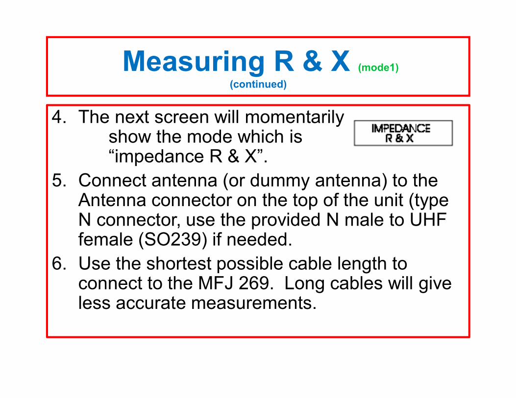
4. The next screen will momentarily show the mode which is “impedance R & X”.
5. Connect antenna (or dummy antenna) to the Antenna connector on the top of the unit (type N connector, use the provided N male to UHF female (SO239) if needed.
6. Use the shortest possible cable length to connect to the MFJ 269. Long cables will give less accurate measurements.
Measuring R & X (mode 1)(continued)
7. Use good quality transmission line if needed to connect between the MFJ 269 to the UUT
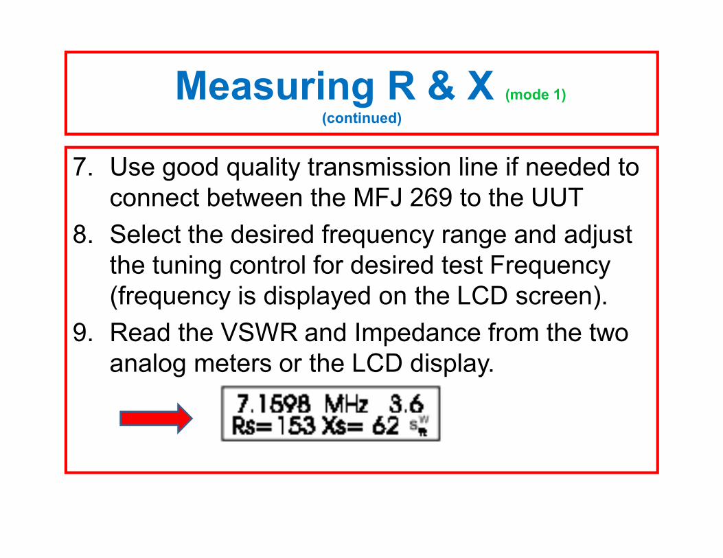
8. Select the desired frequency range and adjust the tuning control for desired test Frequency (frequency is displayed on the LCD screen).
9. Read the VSWR and Impedance from the two analog meters or the LCD display.
Antenna Bandwidth (Mode 1)
1. Connect the antenna to the Antenna jack on the MFJ269.
2. Adjust the frequency until the lowest SWR reading is obtained, this is the center frequency of the Antenna.
3. Move the frequency lower until the SWR reaches 2.5 this is the lower side bandwidth of the antenna.
4. Move the frequency higher until the SWR reaches 2.5, this is the upper side bandwidth of the antenna,
Antenna Bandwidth (mode 1)(continued)
5. Subtract the lower frequency from the higher frequency. The result is the 2.5 SWR bandwidth of the antenna at the previously noted center frequency.
6. The 2.5 SWR limit of was chosen for this example. Use whatever limit the manufacturer specifies or that you want to set for your transmitter.
Measuring Coax. Loss (mode 2)
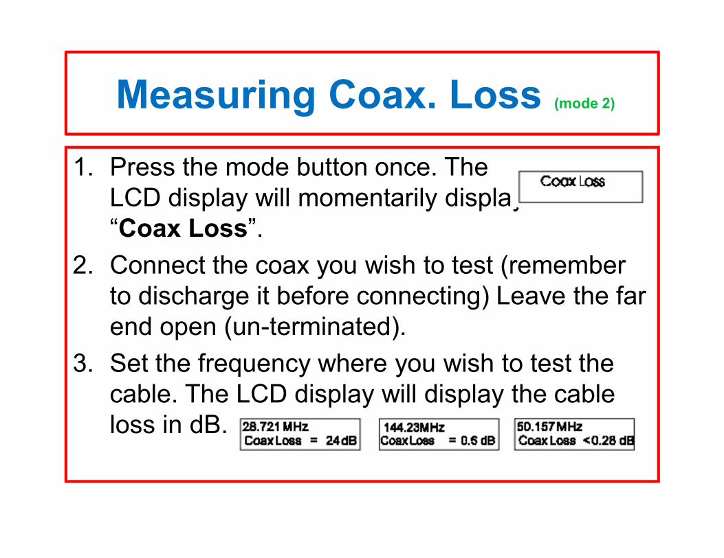
1. Press the mode button once. The LCD display will momentarily display “Coax Loss”.
2. Connect the coax you wish to test (remember to discharge it before connecting) Leave the far end open (un-terminated).
3. Set the frequency where you wish to test the cable. The LCD display will display the cable loss in dB.
Measuring Capacitance (mode 3)
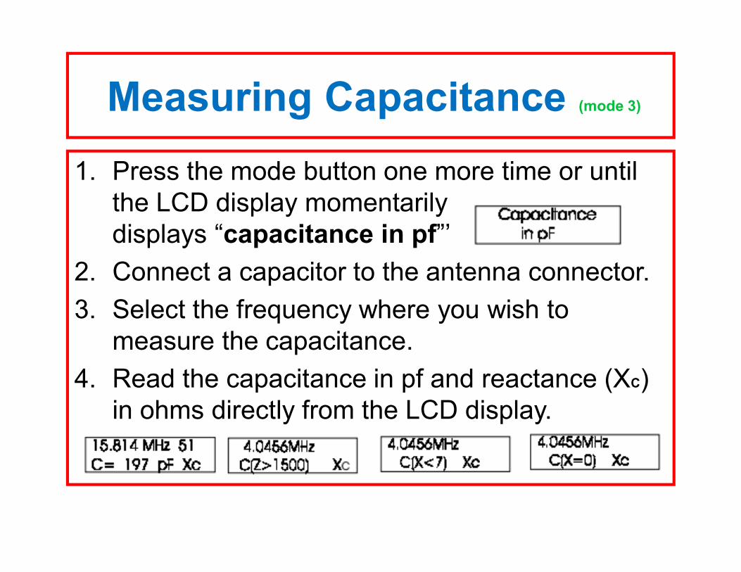
1. Press the mode button one more time or until the LCD display momentarily displays “capacitance in pf”’
2. Connect a capacitor to the antenna connector.3. Select the frequency where you wish to
measure the capacitance.4. Read the capacitance in pf and reactance (XC)
in ohms directly from the LCD display.
Measuring Inductance (mode 4)
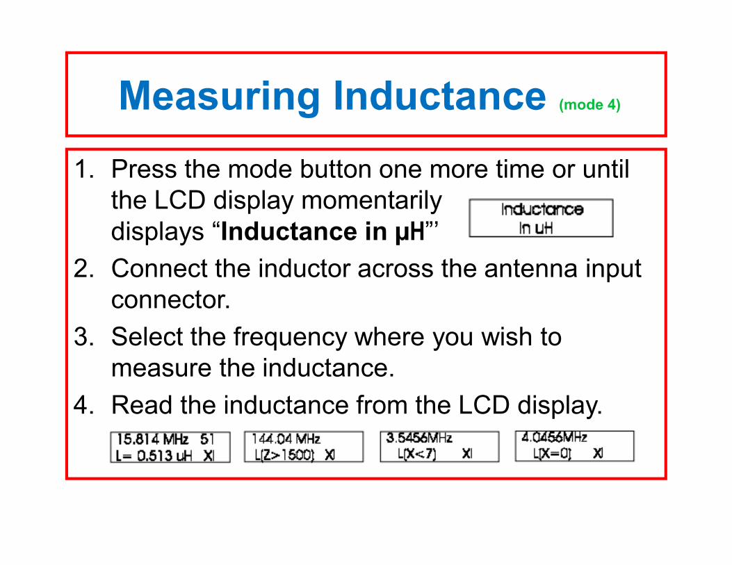
1. Press the mode button one more time or until the LCD display momentarily displays “Inductance in µH”’
2. Connect the inductor across the antenna input connector.
3. Select the frequency where you wish to measure the inductance.
4. Read the inductance from the LCD display.
Measuring Frequency (mode 5)
1. Press the mode button one more time or until the LCD display momentarily displays “Frequency”’
2. Insure the signal you want to measure has no DC component and is less than 2 volts peak (1.4 volts RMS)
3. Connect the frequency to be measured to the “Frequency counter input” BNC connector.
Measuring Frequency (continued)
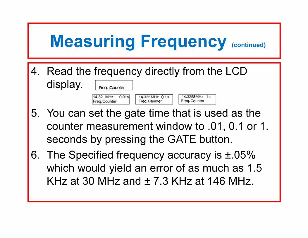
4. Read the frequency directly from the LCD display.
5. You can set the gate time that is used as the counter measurement window to .01, 0.1 or 1. seconds by pressing the GATE button.
6. The Specified frequency accuracy is ±.05% which would yield an error of as much as 1.5 KHz at 30 MHz and ± 7.3 KHz at 146 MHz.
Measuring Frequency (mode 5) (continued)
7. The longer the gate time the more frequency resolution the display will have. 1. A one second gate time give 1 Hz resolution2. A 0.1 second gate time give 10 Hz resolution3. A 0.01 second gate time give 100 Hz resolution
8. The 0.05% overall accuracy of the counter is not accurate enough to verify that your HT is on frequency.
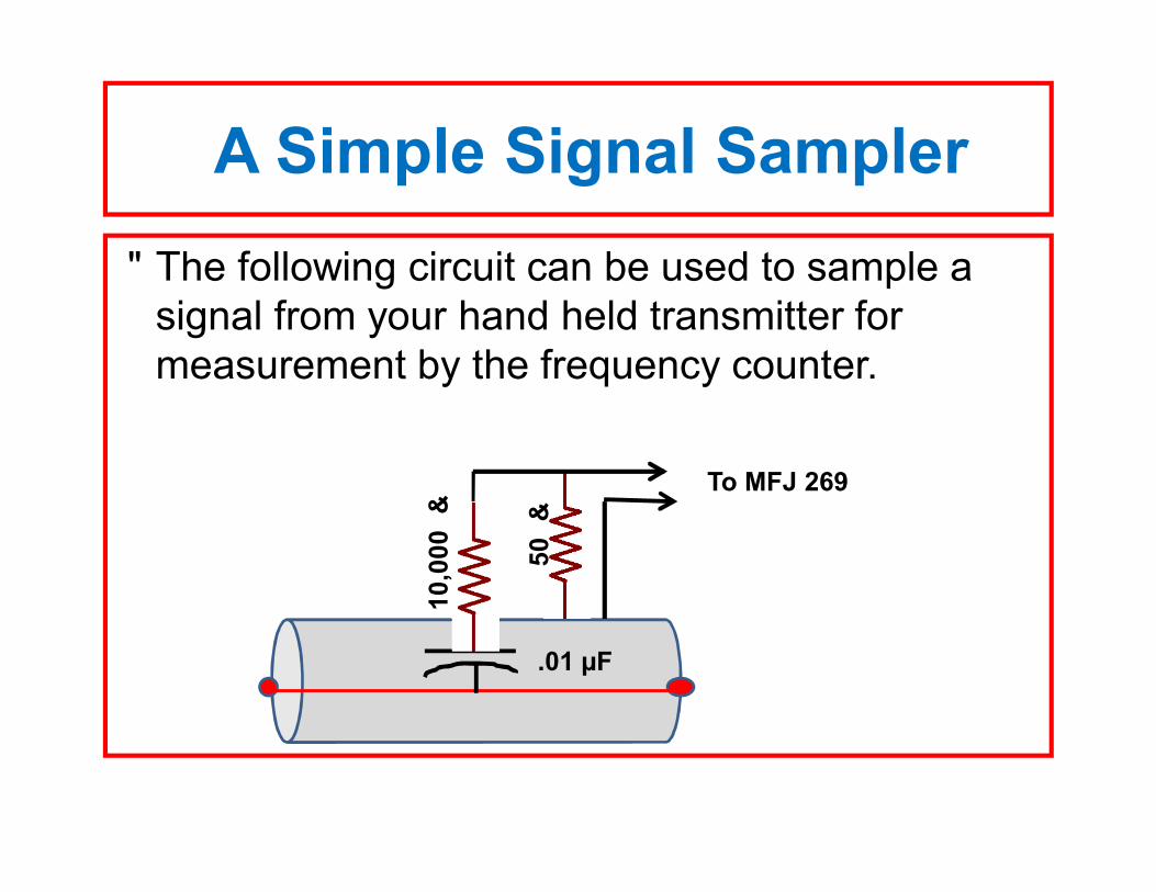
A Simple Signal Sampler• The following circuit can be used to sample a
signal from your hand held transmitter for measurement by the frequency counter.
50 Ω
10,0
00 Ω
.01 µF
To MFJ 269
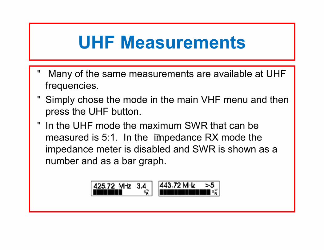
UHF Measurements• Many of the same measurements are available at UHF
frequencies. • Simply chose the mode in the main VHF menu and then
press the UHF button. • In the UHF mode the maximum SWR that can be
measured is 5:1. In the “impedance RX mode the impedance meter is disabled and SWR is shown as a number and as a bar graph.
Advanced Measurements 1. In addition to the measurements available in
the basic, turn on mode, there three additional measurement modes available in the advanced mode.
2. To access the advanced modes press and hold the gate and mode keys down until “the display shows “Advanced 1”
Advanced 1(mode 1)
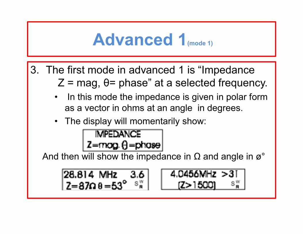
3. The first mode in advanced 1 is “Impedance Z = mag, θ= phase” at a selected frequency.
• In this mode the impedance is given in polar form as a vector in ohms at an angle in degrees.
• The display will momentarily show:
And then will show the impedance in Ω and angle in ø°
Advanced 1(mode 1)
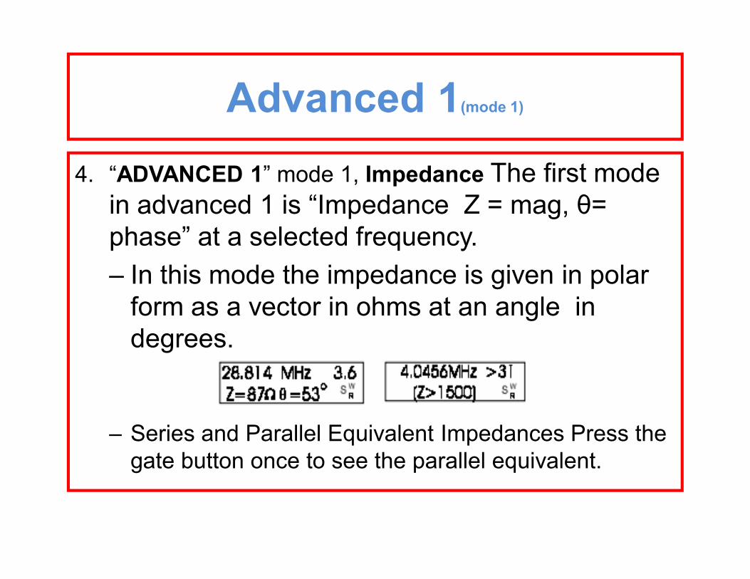
4. “ADVANCED 1” mode 1, Impedance The first mode in advanced 1 is “Impedance Z = mag, θ= phase” at a selected frequency.– In this mode the impedance is given in polar
form as a vector in ohms at an angle in degrees.
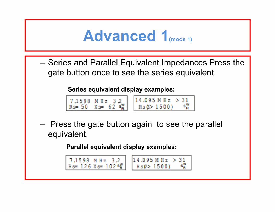
– Series and Parallel Equivalent Impedances Press the gate button once to see the parallel equivalent.
Advanced 1(mode 1)
– Series and Parallel Equivalent Impedances Press the gate button once to see the series equivalent
Series equivalent display examples:
– Press the gate button again to see the parallel equivalent.
Parallel equivalent display examples:
Advanced 1(mode 1)
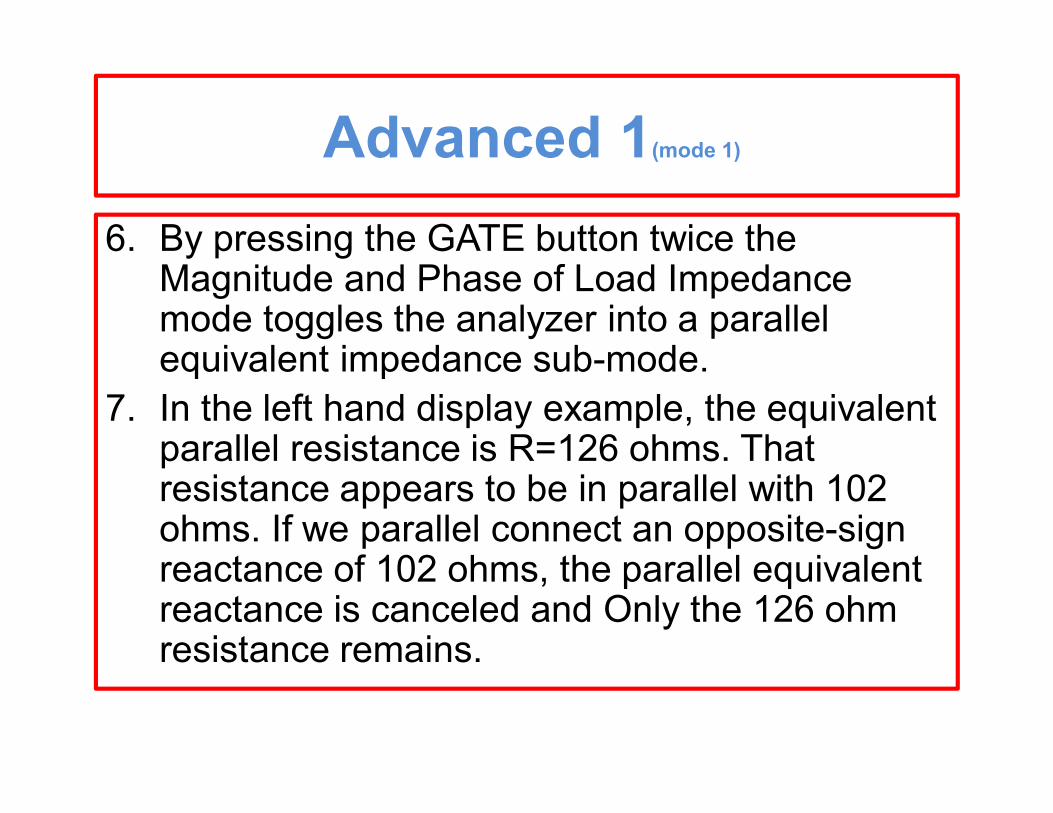
6. By pressing the GATE button twice the Magnitude and Phase of Load Impedance mode toggles the analyzer into a parallel equivalent impedance sub-mode.
7. In the left hand display example, the equivalent parallel resistance is R=126 ohms. That resistance appears to be in parallel with 102 ohms. If we parallel connect an opposite-sign reactance of 102 ohms, the parallel equivalent reactance is canceled and Only the 126 ohm resistance remains.
Advanced 1(mode 1)
6. This is a powerful tool used in matching antennas. The MFJ-269 places that tool at your fingertips. By checking a load for both Rp and Rs, you can see if either is close to the desired resistance. If one resistance value is close to the desired value, adding only one component will match the load by canceling reactance.
Advanced 1(mode 2)
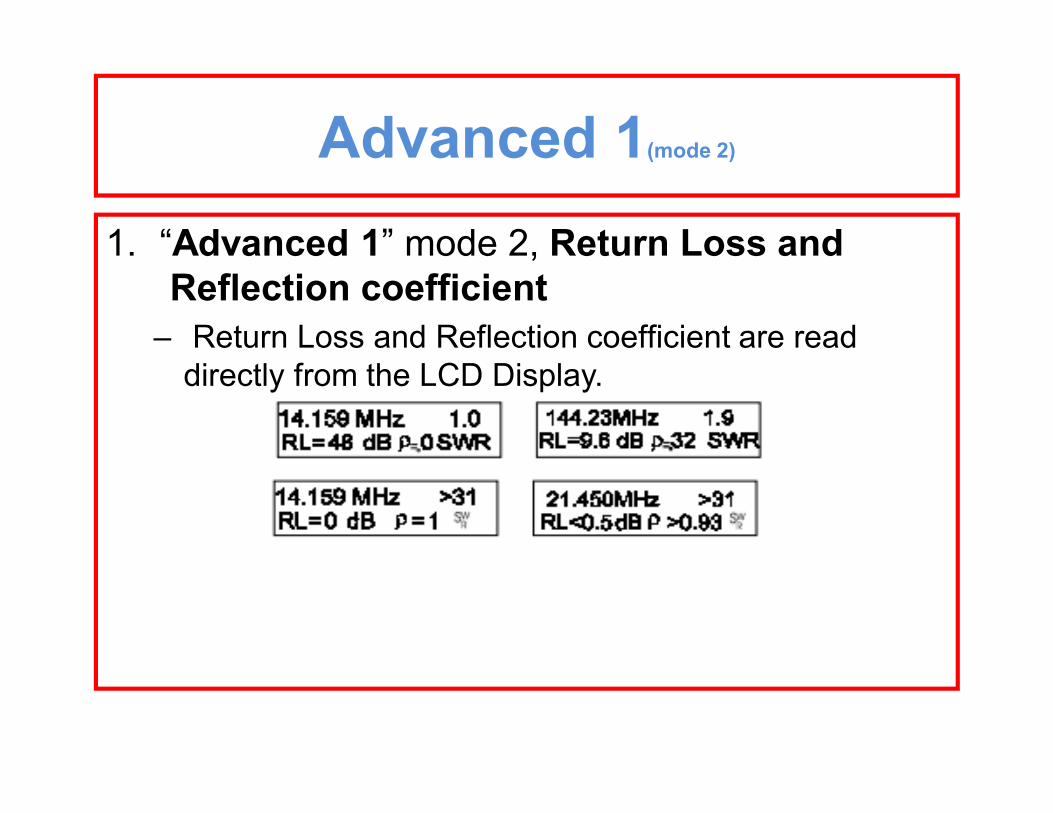
1. “Advanced 1” mode 2, Return Loss and Reflection coefficient
– Return Loss and Reflection coefficient are read directly from the LCD Display.
Advanced 1(mode 3)
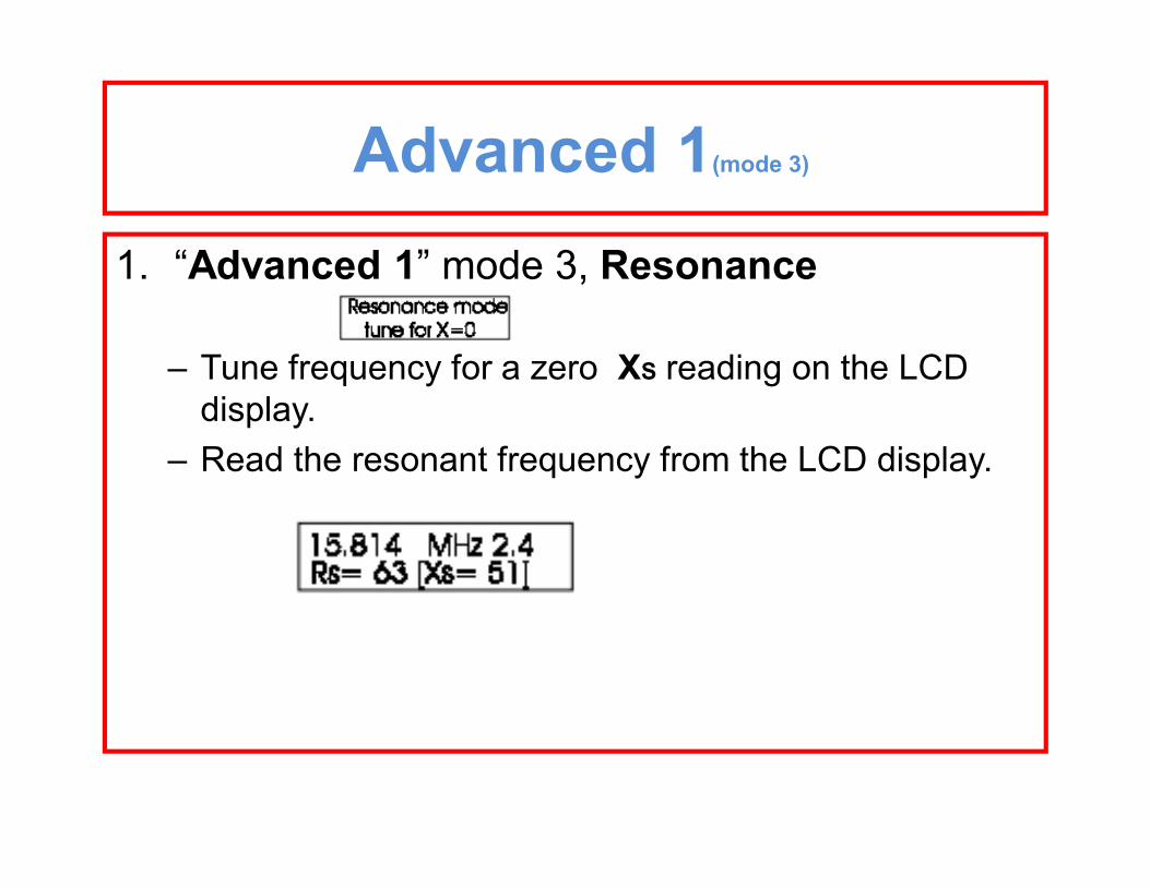
1. “Advanced 1” mode 3, Resonance
– Tune frequency for a zero XS reading on the LCD display.
– Read the resonant frequency from the LCD display.
Advanced 1(mode 4)
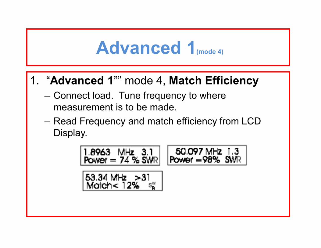
1. “Advanced 1”” mode 4, Match Efficiency– Connect load. Tune frequency to where
measurement is to be made. – Read Frequency and match efficiency from LCD
Display.
Advanced 1(mode 4 continued)
NOTE: Match efficiency ONLY applies to the loss in power transfer from a perfect 50 ohm fixed tuned source to the input of the feedline or system where the measurement is made. It is mostly useful in laboratory situations.
It is not a description of antenna system or feedline efficiency. Even with nearly zero percent match efficiency, an antenna system can radiate applied power with good efficiency. With any given amount of match efficiency your antenna system can be near 100% or near zero percent efficient.
Advanced 21. To get to the advanced 2 mode simultaneously
press and hold the Gate key and the MODE key until advanced 2 is displayed .
2. The advanced 2 mode is related to cable lengths and you will need to input the cable velocity factor for your cable. – The default is .66. use the gate and mode keys to
increment the velocity factor up or down. – simultaneously press and hold the Gate key and the
MODE key to exit the velocity factor set mode.
Advanced 2 (mode 1)
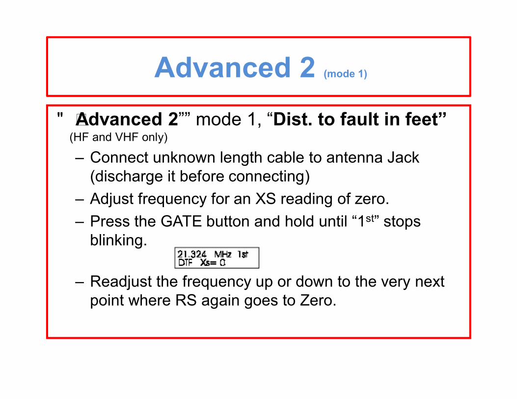
• “Advanced 2”” mode 1, “Dist. to fault in feet” (HF and VHF only)
– Connect unknown length cable to antenna Jack (discharge it before connecting)
– Adjust frequency for an XS reading of zero. – Press the GATE button and hold until “1st” stops
blinking.
– Readjust the frequency up or down to the very next point where RS again goes to Zero.
Advanced 2 (mode 1 continued)
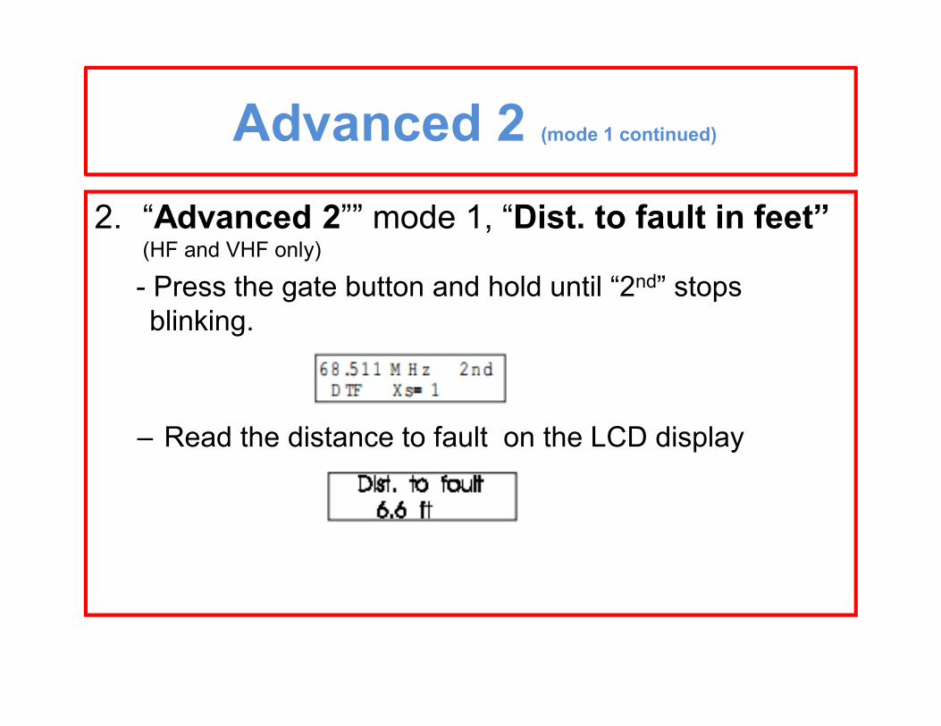
2. “Advanced 2”” mode 1, “Dist. to fault in feet” (HF and VHF only)
- Press the gate button and hold until “2nd” stops blinking.
– Read the distance to fault on the LCD display
Advanced 2 (mode 2)
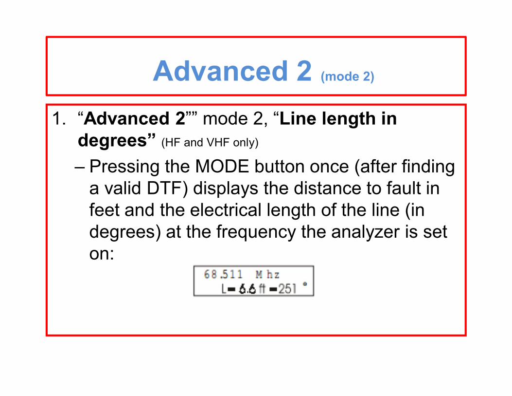
1. “Advanced 2”” mode 2, “Line length in degrees” (HF and VHF only)
– Pressing the MODE button once (after finding a valid DTF) displays the distance to fault in feet and the electrical length of the line (in degrees) at the frequency the analyzer is set on:
Advanced 2 (mode 3)
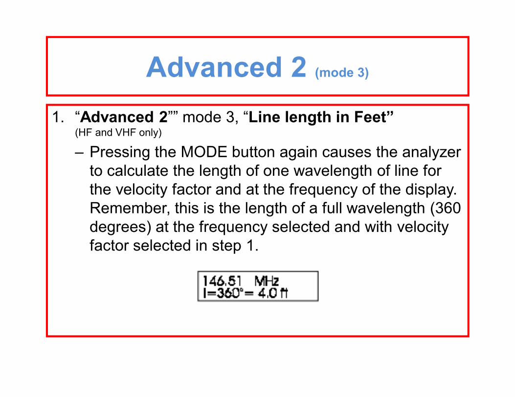
1. “Advanced 2”” mode 3, “Line length in Feet” (HF and VHF only)
– Pressing the MODE button again causes the analyzer to calculate the length of one wavelength of line for the velocity factor and at the frequency of the display. Remember, this is the length of a full wavelength (360 degrees) at the frequency selected and with velocity factor selected in step 1.
Advanced 3 (mode 1)
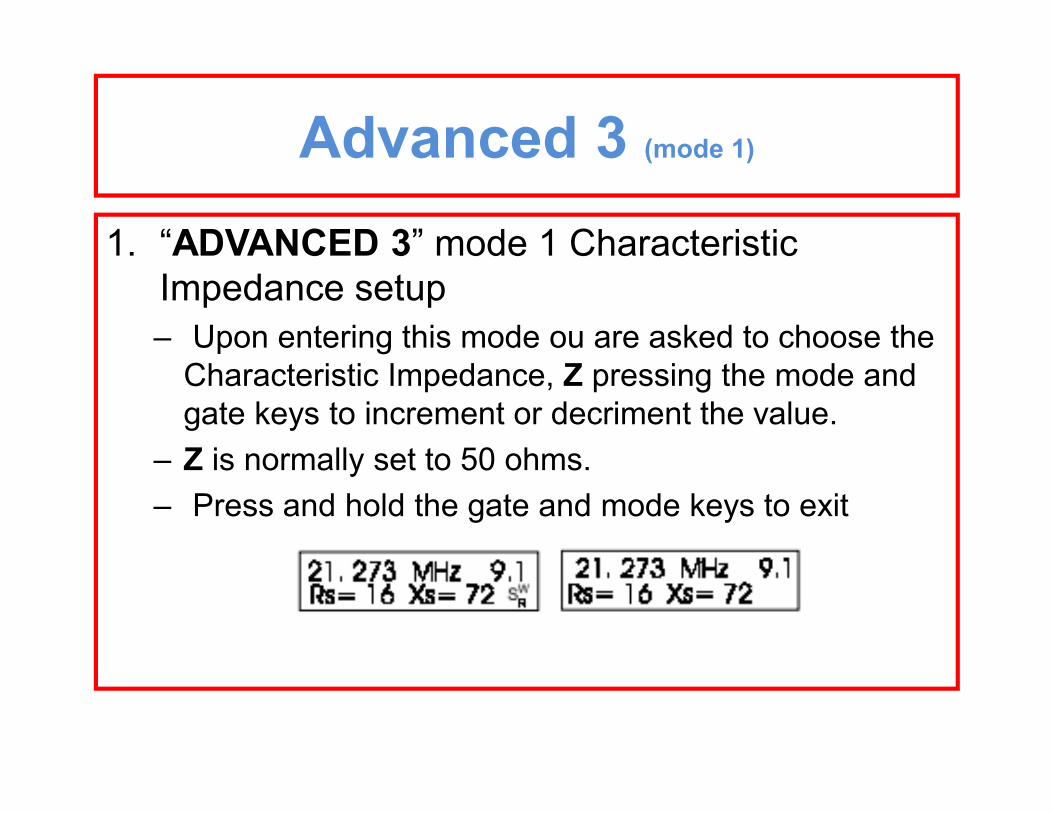
1. “ADVANCED 3” mode 1 Characteristic Impedance setup – Upon entering this mode ou are asked to choose the
Characteristic Impedance, Z pressing the mode and gate keys to increment or decriment the value.
– Z is normally set to 50 ohms.– Press and hold the gate and mode keys to exit
Advanced 3 (mode 1)
1. “ADVANCED 3”, mode 1, Characteristic Impedance setup – The flashing “swr” on the display means the display is
indicating SWR referenced to a new Zo. The meter – continues to indicate 50 ohm SWR .
Advanced 3 (mode 2)
• “ADVANCED 3” mode 2, Coaxial loss– This mode measures coax loss for the line Zo selected in 5.6.1.
it is important that the line is not terminated in – any sort or dissipative load when making this measurement.
Any Questions??
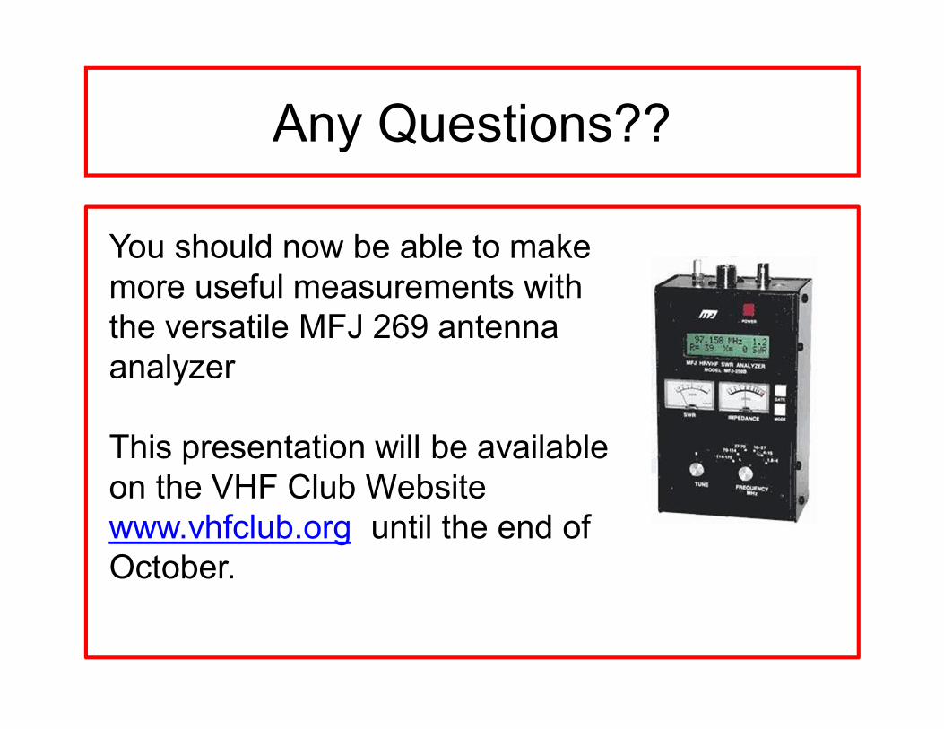
You should now be able to make more useful measurements with the versatile MFJ 269 antenna analyzer
This presentation will be available on the VHF Club Website www.vhfclub.org until the end of October.