Embed Size (px)
Citation preview
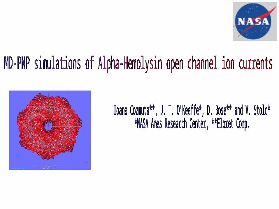
The alpha hemolysin ion channel
‘Natural’ function*
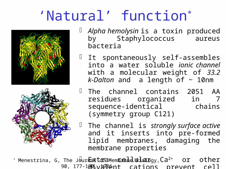
Alpha hemolysin is a toxin produced by Staphylococcus aureus bacteria
It spontaneously self-assembles into a water soluble ionic channel with a molecular weight of 33.2 k-Dalton and a length of ~ 10nm
The channel contains 2051 AA residues organized in 7 sequence-identical chains (symmetry group C121)
The channel is strongly surface active and it inserts into pre-formed lipid membranes, damaging the membrane properties
Extra cellular Ca2+ or other divalent cations prevent cell damage by closing the channel
* Menestrina, G, The Journal of Membrane Biology, 90, 177-190, 1986
Experiments
Over-linear
Conductance*
* Biophysical Journal, 79, 4, 1967-1975, 2001
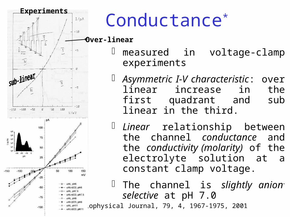
measured in voltage-clamp experiments
Asymmetric I-V characteristic: over linear increase in the first quadrant and sub linear in the third.
Linear relationship between the channel conductance and the conductivity (molarity) of the electrolyte solution at a constant clamp voltage.
The channel is slightly anion- selective at pH 7.0
polymer speed inhibition
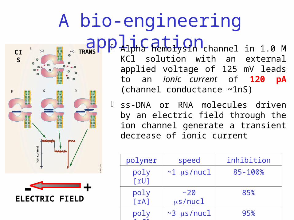
poly [rU] ~1 s/nucl 85-100%
poly [rA] ~20 s/nucl 85%
poly [rC] ~3 s/nucl 95%ELECTRIC FIELD- +
CIS TRANS
A bio-engineering application Alpha hemolysin channel in 1.0 M KCl
solution with an external applied voltage of 125 mV leads to an ionic current of 120 pA (channel conductance ~1nS)
ss-DNA or RNA molecules driven by an electric field through the ion channel generate a transient decrease of ionic current
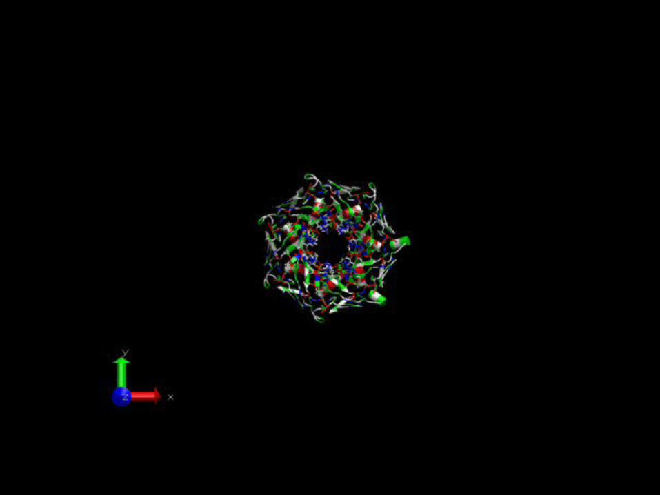
An atomistic view of the channel
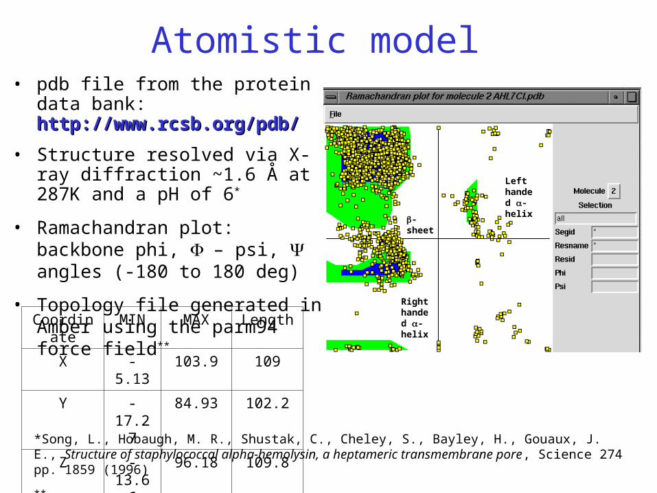
*Song, L., Hobaugh, M. R., Shustak, C., Cheley, S., Bayley, H., Gouaux, J. E., Structure of staphylococcal alpha-hemolysin, a heptameric transmembrane pore, Science 274 pp. 1859 (1996)
**Force field: Cornell et al, 1995 –AMBER, http://www.scripps.edu/
Coordinate MIN MAX Length
X -5.13 103.9 109
Y -17.27 84.93 102.2
Z -13.66 96.18 109.8
-sheet
Right handed -helix
Left handed -helix
Atomistic model• pdb file from the protein data bank:
http://www.rcsb.org/pdb/http://www.rcsb.org/pdb/
• Structure resolved via X-ray diffraction ~1.6 Å at 287K and a pH of 6*
• Ramachandran plot: backbone phi, – psi, angles (-180 to 180 deg)
• Topology file generated in Amber using the parm94 force field**
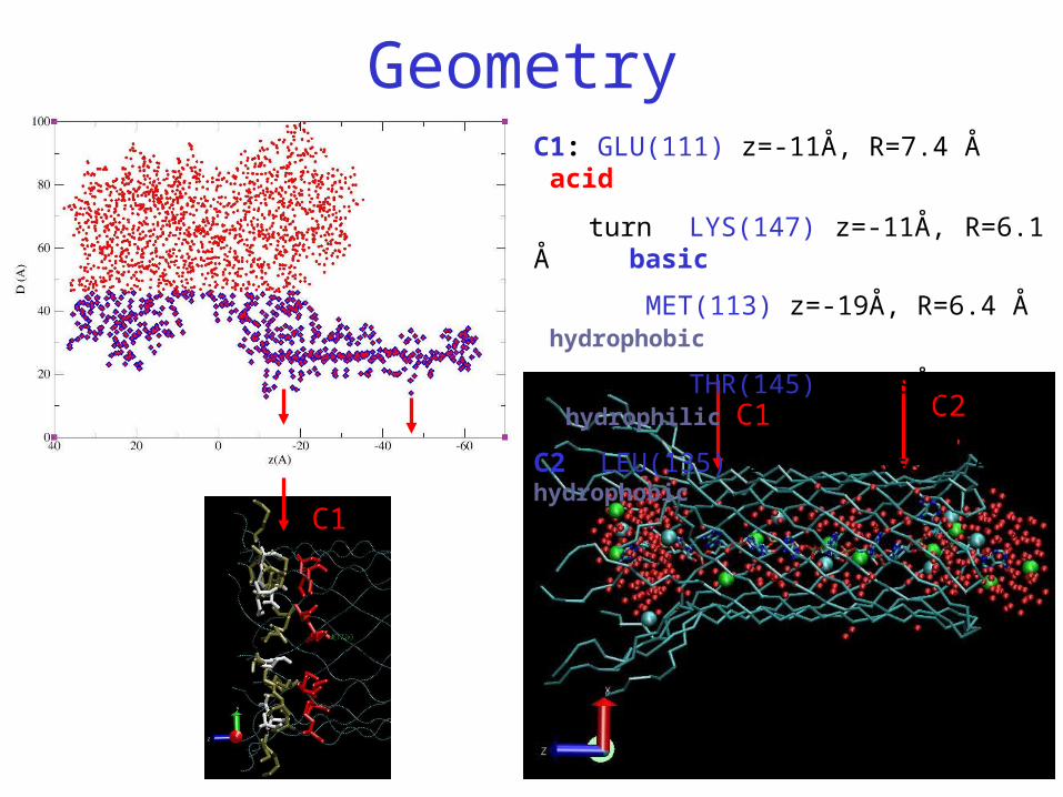
Geometry
C1 C2
C1: GLU(111) z=-11Å, R=7.4 Å acid
turn LYS(147) z=-11Å, R=6.1 Å basic
MET(113) z=-19Å, R=6.4 Å hydrophobic
turn THR(145) z=-19Å, R=8.2 Å hydrophilic
C2: LEU(135) z=-47Å, R=6.3 Å hydrophobic
C1
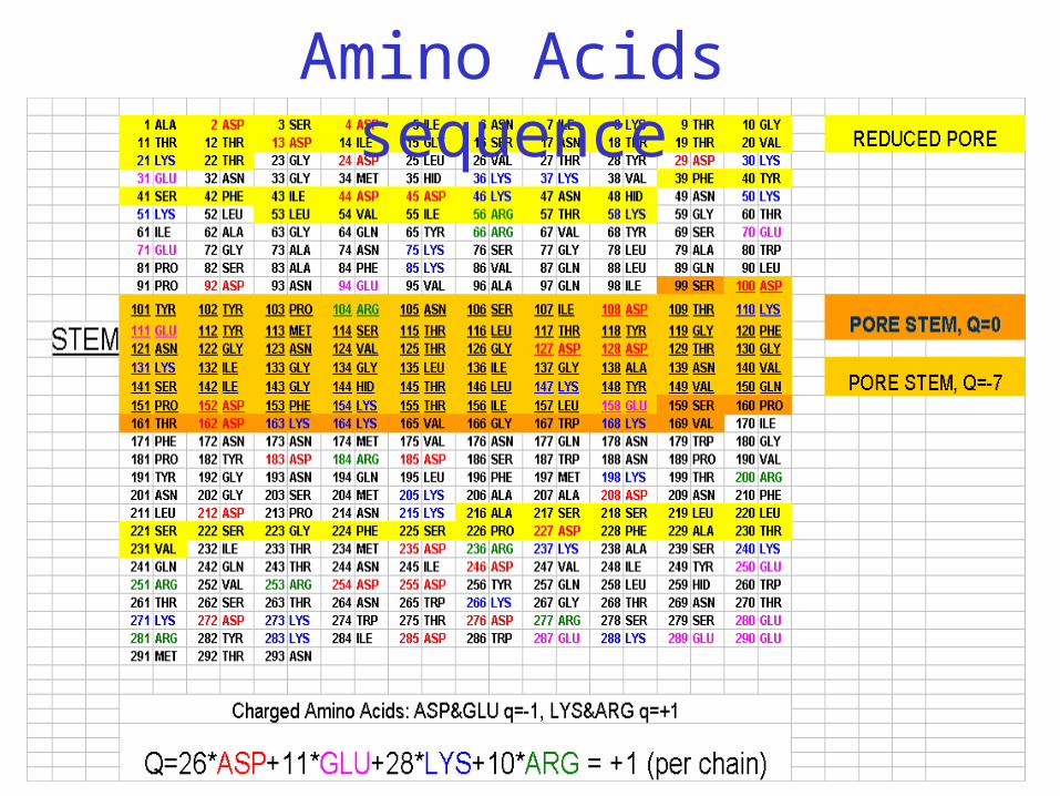
Amino Acids sequence
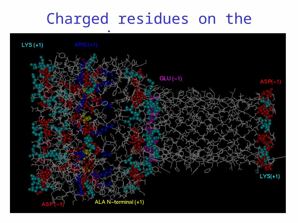
Charged residues on the inner pore

The MD-PNP model
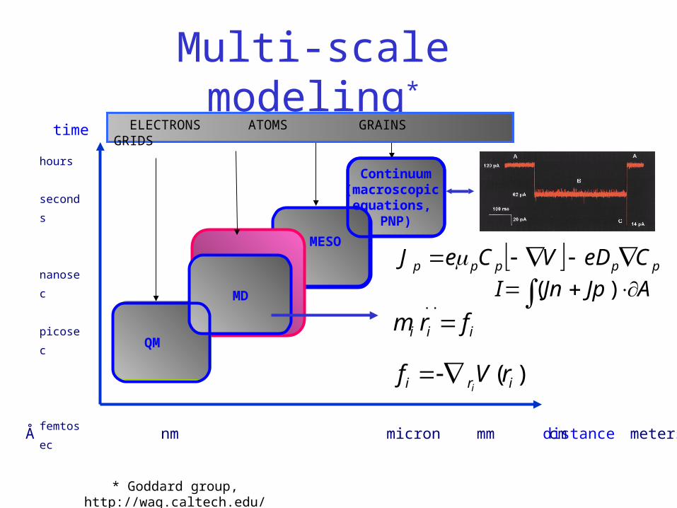
Multi-scale modeling*
distance Å nm micron mm cm meters
hours
seconds
nanosec
picosec
femtosec
time
MESO
QM
MD
ELECTRONS ATOMS GRAINS GRIDS
Continuum(macroscopic
equations, PNP)
)(
..
iri
iii
rVf
frm
i
ppppp CeDVCeJ
AJpJnI )(
* Goddard group, http://wag.caltech.edu/
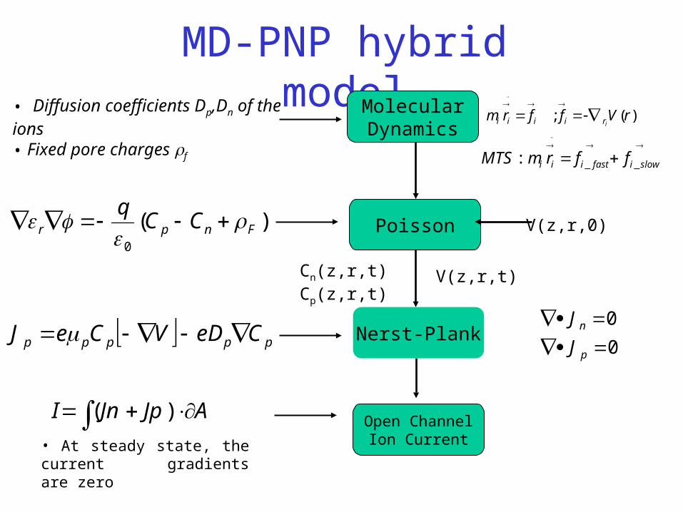
MD-PNP hybrid model
Poisson V(z,r,0))(0
Fnpr CCq
• Diffusion coefficients Dp,Dn of the ions• Fixed pore charges f
MolecularDynamics
• At steady state, the current gradients are zero
AJpJnI )( Open ChannelIon Current
0
0
p
n
J
JNerst-Plank
V(z,r,t)Cn(z,r,t)Cp(z,r,t)
ppppp CeDVCeJ
)(; rVffrmiriiii
slowifastiii ffrmMTS __:
MD simulations
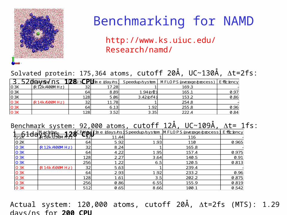
Benchmarking for NAMD
Machine CPU's Time (day/ns) Speedup/system MFLOPS(average/process) EfficiencyO3K (R12k/400MHz) 32 17.28 1 169.3 -O3K 64 8.89 1.94(of2) 165.1 0.97O3K 128 5.06 3.42(of 4) 153.2 0.86O3K (R14k/600MHz) 32 11.78 1 254.8 -O3K 64 6.13 1.92 255.8 0.96O3K 128 3.52 3.35 222.4 0.84
Machine CPU's Time (days/ns) Speedup/system MFLOPS(average/process) EfficiencyO2K (R10k/250MHz) 32 11.44 1 116 -O2K 64 5.92 1.93 110 0.965O3K (R12k/400MHz) 32 8.24 1 165.8 -O3K 64 4.22 1.95 157.4 0.975O3K 128 2.27 3.64 140.5 0.91O3K 256 1.22 6.5 120.5 0.813O3K (R14k/600MHz) 32 5.63 1 239.4 -O3K 64 2.93 1.92 233.2 0.96O3K 128 1.61 3.5 202.2 0.875O3K 256 0.86 6.55 155.9 0.819O3K 512 0.65 8.66 100.1 0.542
Solvated protein: 175,364 atoms, cutoff 20Å, UC~130Å, t=2fs: 3.52days/ns 128 CPU
Benchmark system: 92,000 atoms, cutoff 12Å, UC~109Å, t= 1fs: 1.61days/ns 128 CPU
Actual system: 120,000 atoms, cutoff 20Å, t=2fs (MTS): 1.29 days/ns for 200 CPU
http://www.ks.uiuc.edu/Research/namd/
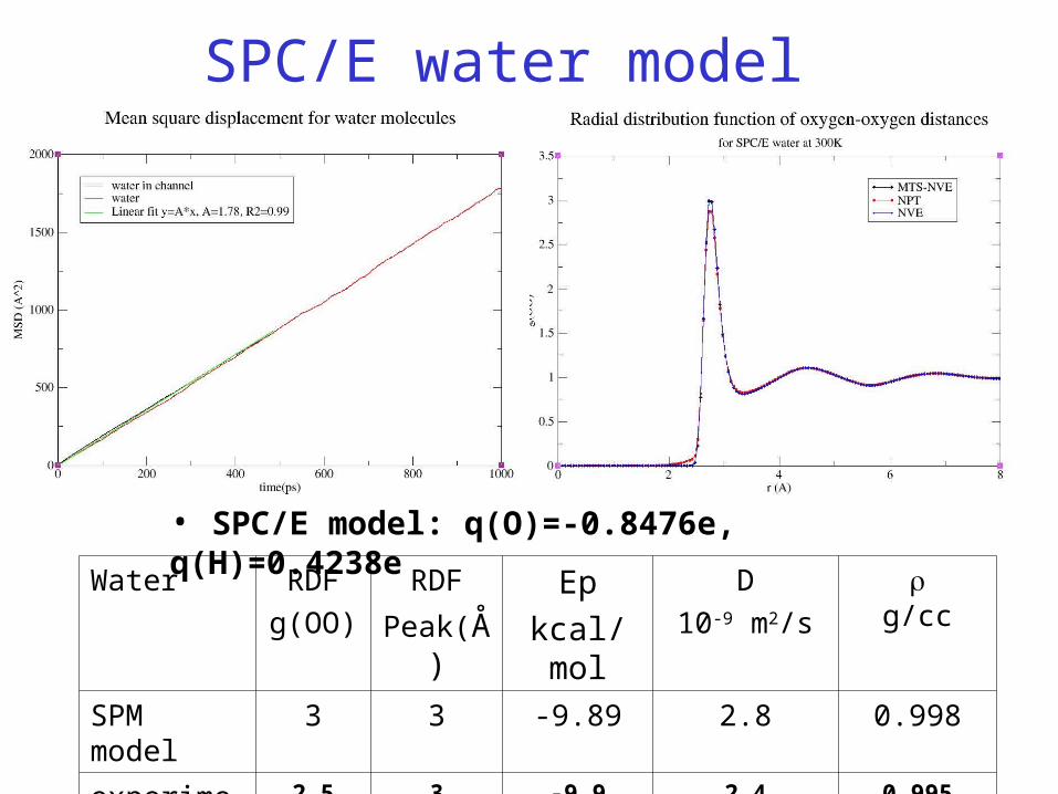
SPC/E water model
• SPC/E model: q(O)=-0.8476e, q(H)=0.4238e
Water RDF
g(OO)
RDF
Peak(Å)Ep
kcal/mol
D
10-9 m2/s
g/cc
SPM model 3 3 -9.89 2.8 0.998
experiments 2.5 3 -9.9 2.4 0.995
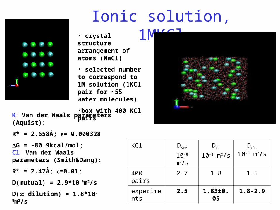
Ionic solution, 1MKCl• crystal structure arrangement of atoms (NaCl)
• selected number to correspond to 1M solution (1KCl pair for ~55 water molecules)
•box with 400 KCl pairs
KCl DSPM
10-9 m2/s
DK+
10-9 m2/s
DCl-
10-9 m2/s
400 pairs 2.7 1.8 1.5
experiments 2.5 1.83±0.05 1.8-2.9
K+ Van der Waals parameters (Aquist):
R* = 2.658Å; = 0.000328
G = -80.9kcal/mol;
Cl- Van der Waals parameters (Smith&Dang):
R* = 2.47Å; =0.01;
D(mutual) = 2.9*10-9m2/s
D( dilution) = 1.8*10-9m2/s
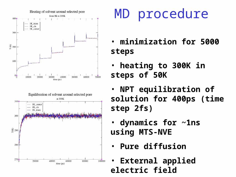
MD procedure
• minimization for 5000 steps
• heating to 300K in steps of 50K
• NPT equilibration of solution for 400ps (time step 2fs)
• dynamics for ~1ns using MTS-NVE
• Pure diffusion
• External applied electric field
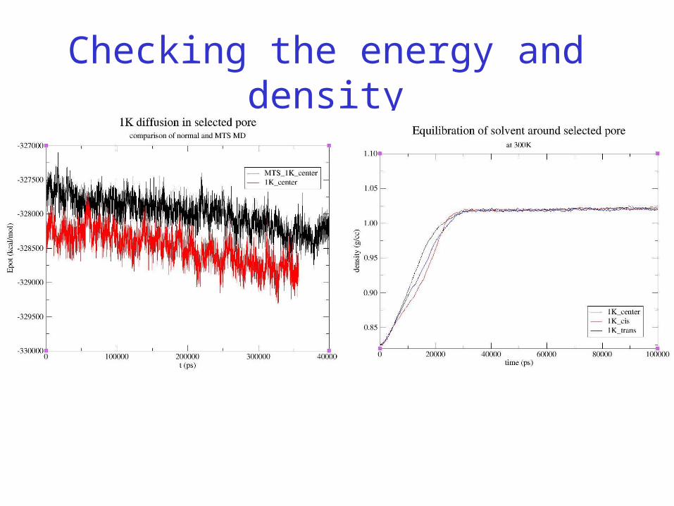
Checking the energy and density
Diffusion coefficients
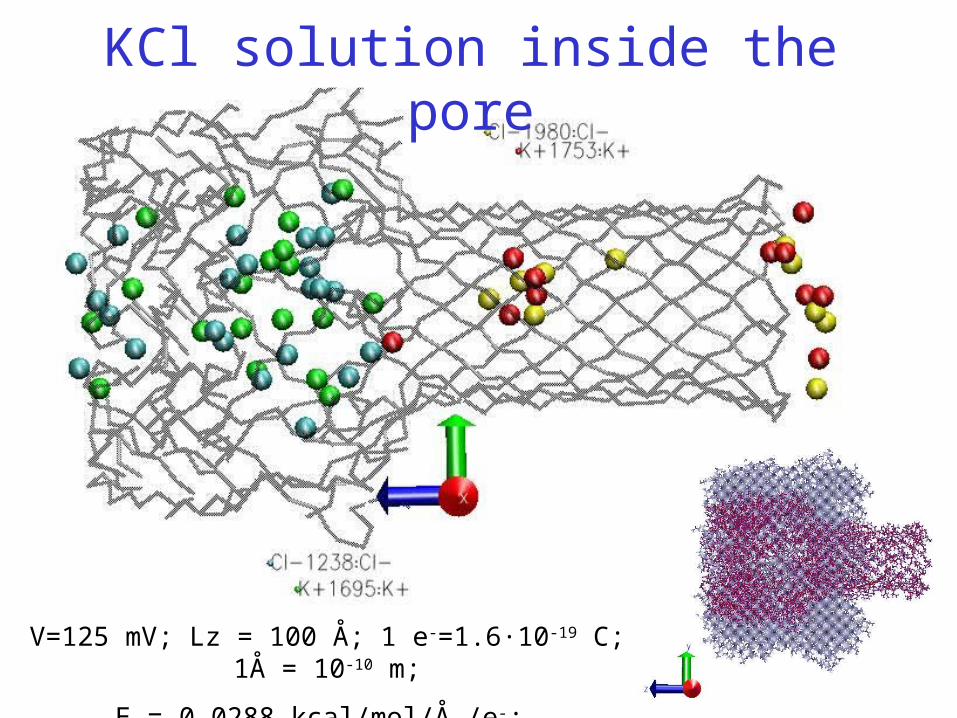
V=125 mV; Lz = 100 Å; 1 e-=1.6·10-19 C; 1Å = 10-10 m;
E = 0.0288 kcal/mol/Å /e-;
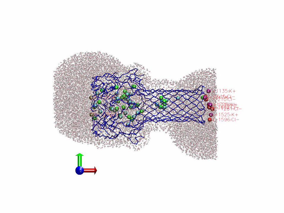
KCl solution inside the pore
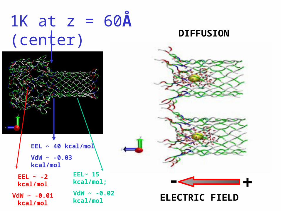
1K at z = 60Å (center)
ELECTRIC FIELD
- +
DIFFUSION
EEL ~ 40 kcal/mol
VdW ~ -0.03 kcal/mol
EEL~ 15 kcal/mol;
VdW ~ -0.02 kcal/mol
EEL ~ -2 kcal/mol
VdW ~ -0.01 kcal/mol
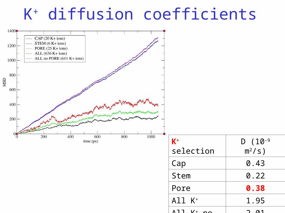
K+ selection D (10-9 m2/s)
Cap 0.43
Stem 0.22
Pore 0.38
All K+ 1.95
All K+ no pore 2.01
K+ diffusion coefficients
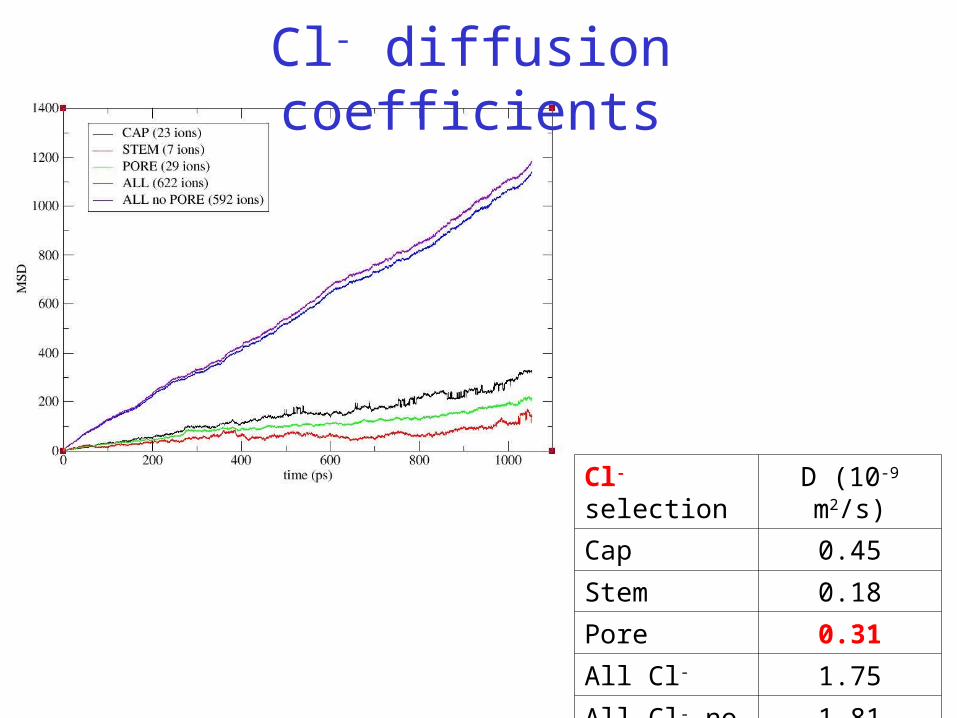
Cl- selection D (10-9 m2/s)
Cap 0.45
Stem 0.18
Pore 0.31
All Cl- 1.75
All Cl- no pore 1.81
Cl- diffusion coefficients
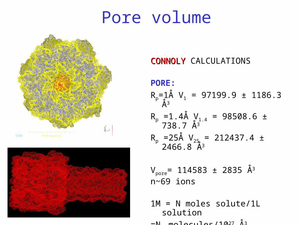
CONNOLYCONNOLY CALCULATIONS
PORE:
Rp=1Å V1 = 97199.9 ± 1186.3 Å3
Rp =1.4Å V1.4 = 98508.6 ± 738.7 Å3
Rp =25Å V25 = 212437.4 ± 2466.8 Å3
Vpore= 114583 ± 2835 Å3
n~69 ions
1M = N moles solute/1L solution
=NA molecules/1027 Å3 =6.023E-4 molec/ Å3
Pore volume

Binding energies
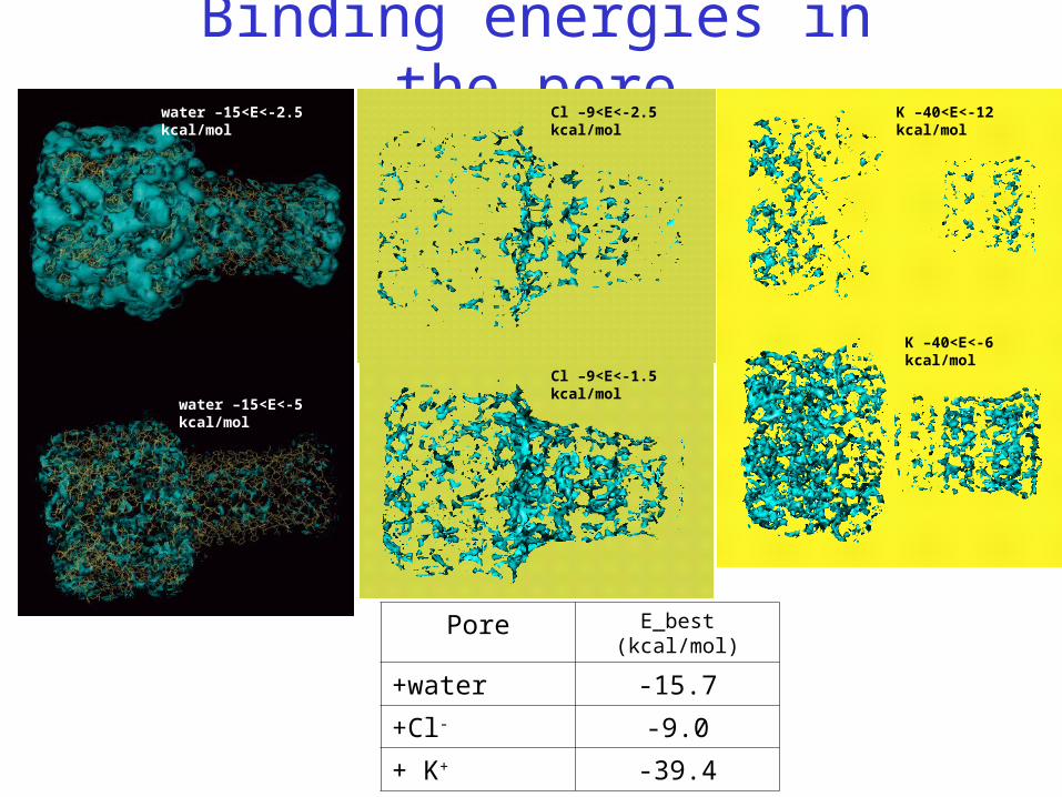
Binding energies in the poreK –40<E<-12 kcal/mol
K –40<E<-6 kcal/mol
water –15<E<-5 kcal/mol
water –15<E<-2.5 kcal/mol Cl –9<E<-2.5 kcal/mol
Cl –9<E<-1.5 kcal/mol
Pore E_best (kcal/mol)
+water -15.7
+Cl- -9.0
+ K+ -39.4
PNP simulations
z
r
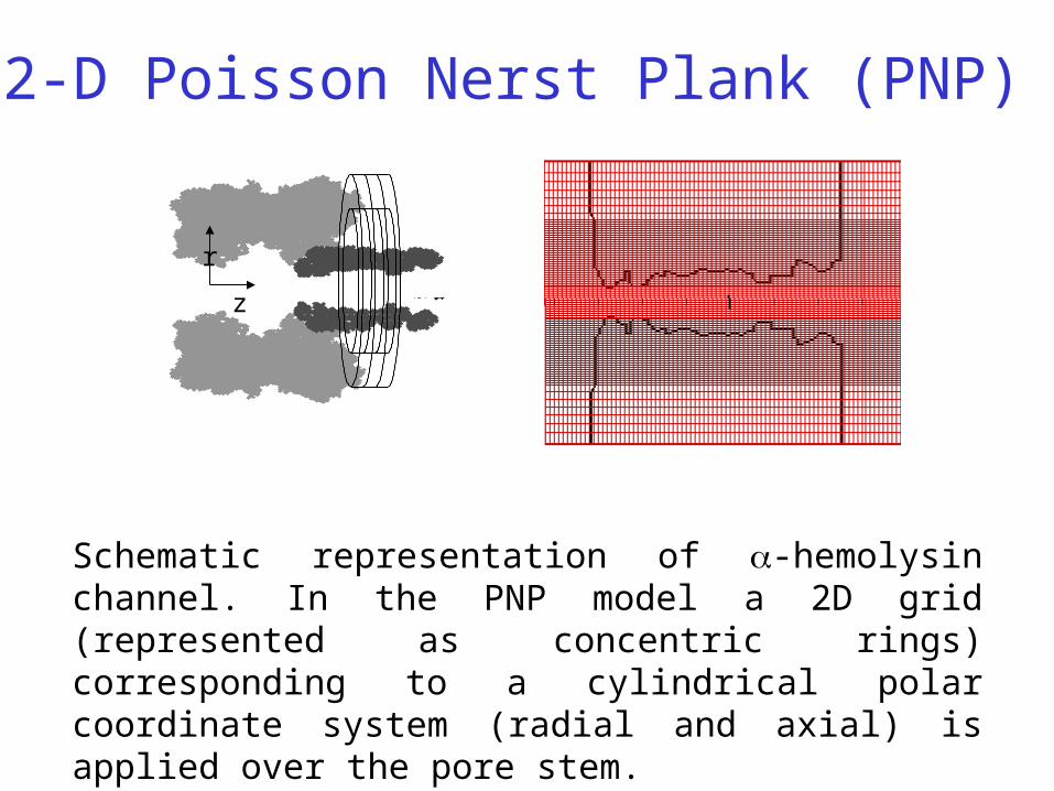
Schematic representation of -hemolysin channel. In the PNP model a 2D grid (represented as concentric rings) corresponding to a cylindrical polar coordinate system (radial and axial) is applied over the pore stem.
2-D Poisson Nerst Plank (PNP)
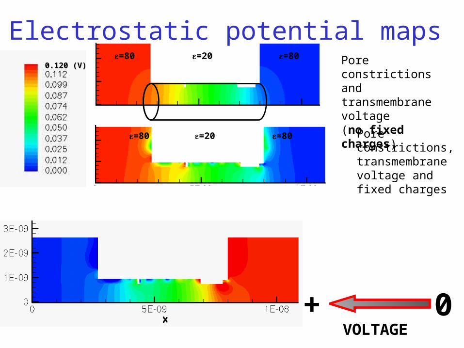
Pore constrictions and transmembrane voltage(no fixed charges)
VOLTAGE+ 0
0.120 (V)0.120 (V)=20 =80=80
Pore constrictions, transmembrane voltage and fixed charges
Electrostatic potential maps
=80 =80=20
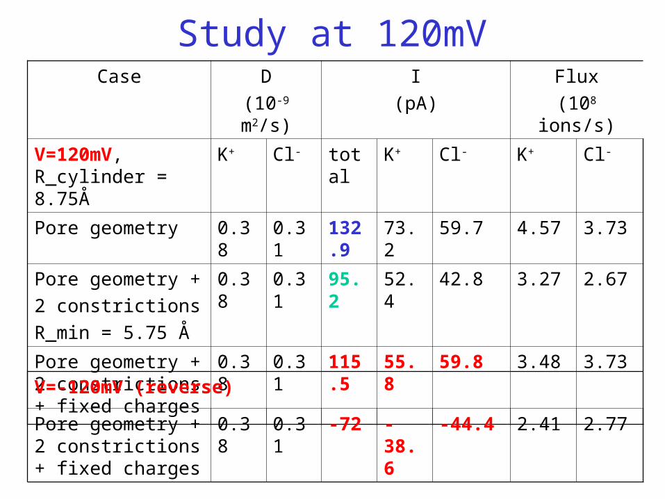
Study at 120mVCase D
(10-9 m2/s)
I
(pA)
Flux
(108 ions/s)
V=120mV, R_cylinder = 8.75Å
K+ Cl- total K+ Cl- K+ Cl-
Pore geometry 0.38 0.31 132.9 73.2 59.7 4.57 3.73
Pore geometry +
2 constrictions
R_min = 5.75 Å
0.38 0.31 95.2 52.4 42.8 3.27 2.67
Pore geometry + 2 constrictions + fixed charges
0.38 0.31 115.5 55.8 59.8 3.48 3.73
V=-120mV (reverse)
Pore geometry + 2 constrictions + fixed charges
0.38 0.31 -72 -38.6 -44.4 2.41 2.77
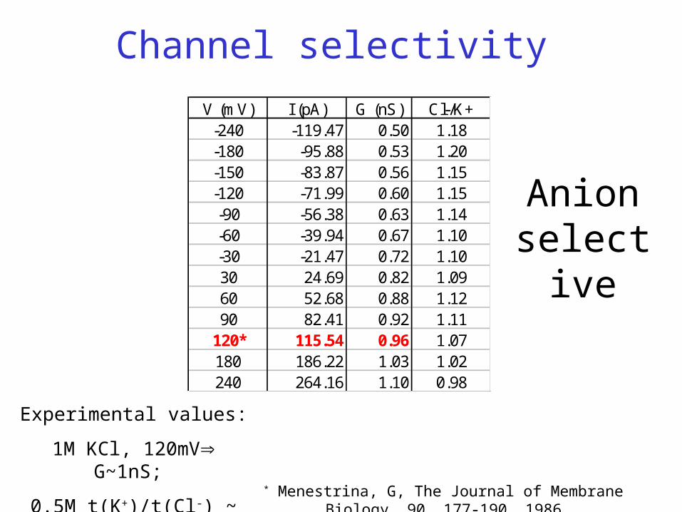
V (mV) I (pA) G (nS) Cl-/K+-240 -119.47 0.50 1.18-180 -95.88 0.53 1.20-150 -83.87 0.56 1.15-120 -71.99 0.60 1.15-90 -56.38 0.63 1.14-60 -39.94 0.67 1.10-30 -21.47 0.72 1.1030 24.69 0.82 1.0960 52.68 0.88 1.1290 82.41 0.92 1.11
120* 115.54 0.96 1.07180 186.22 1.03 1.02240 264.16 1.10 0.98
Channel selectivity
* Menestrina, G, The Journal of Membrane Biology, 90, 177-190, 1986
Experimental values:
1M KCl, 120mV G~1nS;
0.5M t(K+)/t(Cl-) ~ 1.5
Anion selective
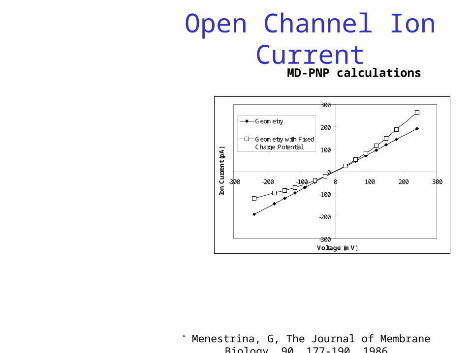
Open Channel Ion Current
-300
-200
-100
0
100
200
300
-300 -200 -100 0 100 200 300
Voltage (mV)
Ion
Cu
rren
t (p
A)
Geometry
Geometry with FixedCharge Potential
MD-PNP calculations
* Menestrina, G, The Journal of Membrane Biology, 90, 177-190, 1986
CONCLUSIONS The MD calculations show that both K+ and Cl- ions are transported through the -
hemolysin channel The ions diffusion coefficient inside the pore is reduced by a factor of ~5 for K+ and
~6 for Cl- compared to pure solution. Overall (in solution and in the pore) D(K+) > D(Cl-) while in the pore-cap D(K+) <
D(Cl-) Binding sites for K+ occur at the two ends of the pore (cis and trans) while for Cl- the
best binding sites are located at the stem-cap connecting region There is a greater binding potential and also more binding sites for K+ than Cl-
2D-PNP model prediction show that I-V behavior is consistent with observed experimental profiles: over-linear for
positive voltages and sub-linear for negative voltages A smooth cylinder would have a larger conductance that is reduced by the presence of
the two constrictions The polar walls of the pore increase the current Channel is slightly anion (Cl-) selective
ACKNOWLEDGEMENTS
• MD simulations with NAMD (http://www.ks.uiuc.edu/Research/namd*)
• Movies and analysis generated with VMD (http://www.ks.uiuc.edu/Research/vmd*)
• Amber, VMD, NAMD lists, GRID (Molecular Inc)
• NAS support group (http://www.nas.nasa.gov)
• System administrators of the Nanotechnology Division: Aldo Foot, Marcy Shull
*VMD/NAMD - developed by the Theoretical and Computational Biophysics Group in the Beckman Institute for Advanced Science and Technology at the University of Illinois at Urbana-Champaign.
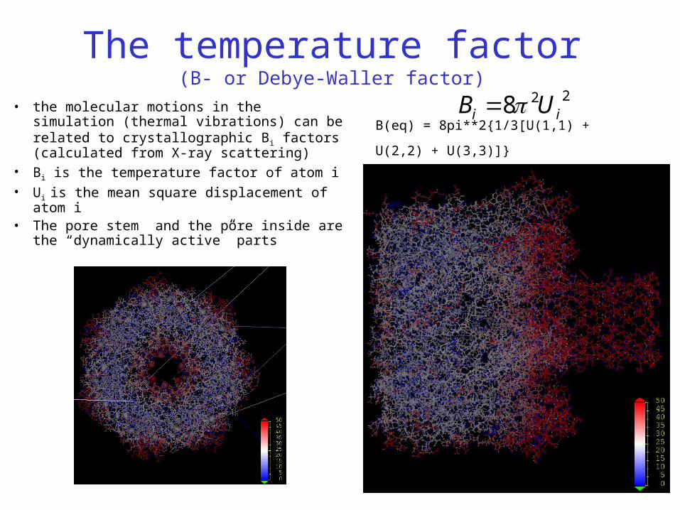
The temperature factor(B- or Debye-Waller factor)
• the molecular motions in the simulation (thermal vibrations) can be related to crystallographic Bi factors (calculated from X-ray scattering)
• Bi is the temperature factor of atom i• Ui is the mean square displacement of atom i• The pore stem and the pore inside are the
“dynamically active” parts
228 ii UB B(eq) = 8pi**2{1/3[U(1,1) + U(2,2) + U(3,3)]}
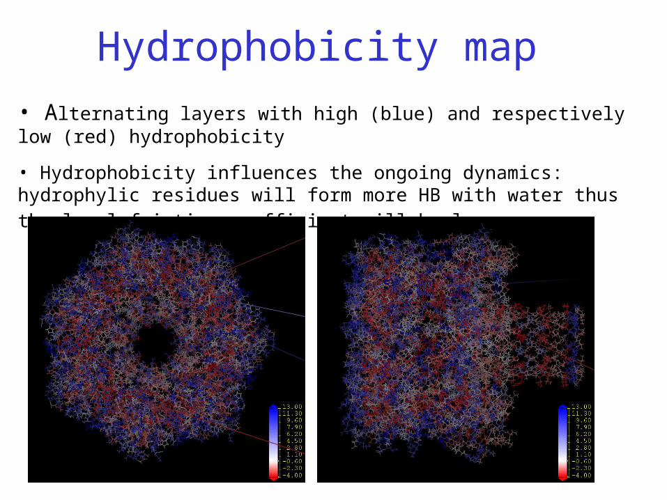
Hydrophobicity map
• Alternating layers with high (blue) and respectively low (red) hydrophobicity
• Hydrophobicity influences the ongoing dynamics: hydrophylic residues will form
more HB with water thus the local friction coefficient will be larger
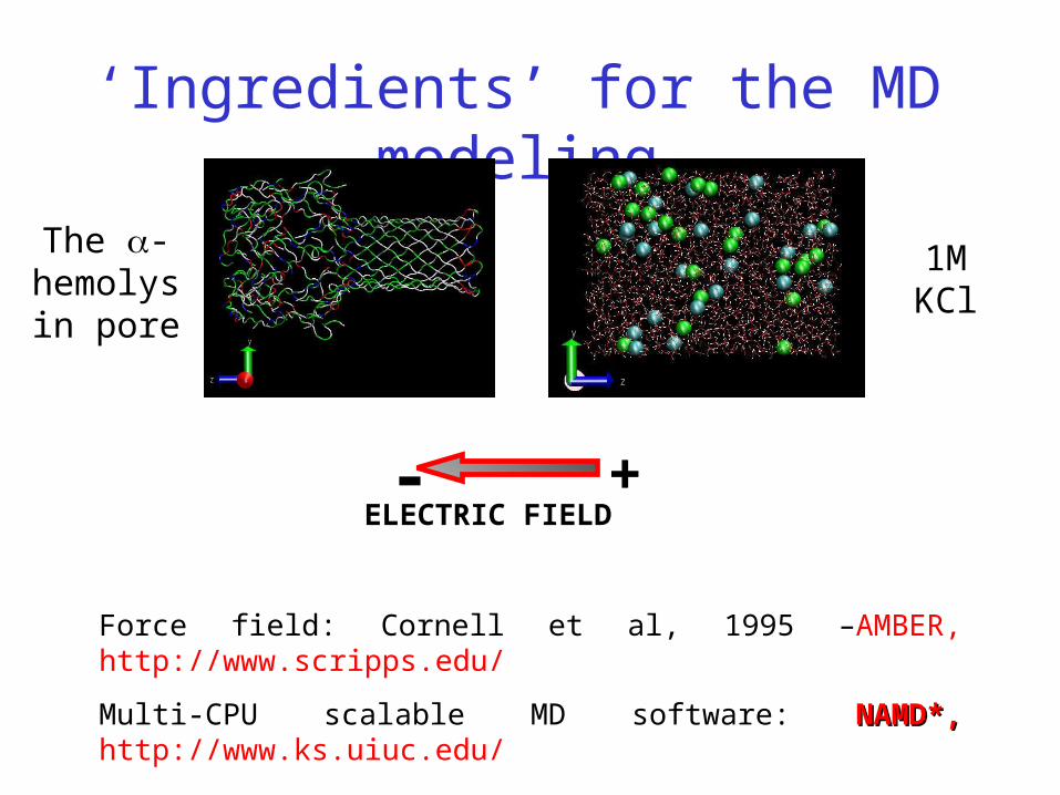
‘Ingredients’ for the MD modeling
ELECTRIC FIELD- +
Force field: Cornell et al, 1995 –AMBER, http://www.scripps.edu/
Multi-CPU scalable MD software: NAMD*, NAMD*, http://www.ks.uiuc.edu/
1M KClThe -hemolysin
pore
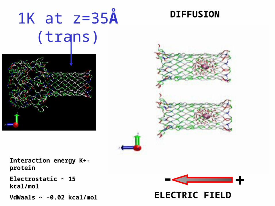
1K at z=35Å (trans) DIFFUSION
ELECTRIC FIELD
- +Interaction energy K+-protein
Electrostatic ~ 15 kcal/mol
VdWaals ~ -0.02 kcal/mol
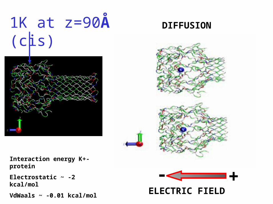
1K at z=90Å (cis) DIFFUSION
ELECTRIC FIELD
- +Interaction energy K+-protein
Electrostatic ~ -2 kcal/mol
VdWaals ~ -0.01 kcal/mol
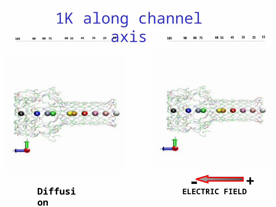
Diffusion ELECTRIC FIELD- +
1K along channel axis25 15105 354560 55758090 25 15105 354560 55758090


![The SUMO Conjugation Complex Self-Assembles into · The SUMO Conjugation Complex Self-Assembles into Nuclear Bodies Independent of SIZ1 and COP11[OPEN] Magdalena J. Mazur,a,2,3 Mark](https://img.pdfslide.us/doc/110x75/5e8594517e7649271123805c/the-sumo-conjugation-complex-self-assembles-the-sumo-conjugation-complex-self-assembles.jpg)