Embed Size (px)
Citation preview
The Alkaline Aluminium Hydrogen Peroxide Semi-Fuel Cell for the Hugin 3000 Autonomous Underwater Vehicle
Øistein Hasvold and Kjell Håvard Johansen FFI (Norwegian Defence Research Establishment)
P O Box 25, N-2027 Kjeller, Norway [email protected], [email protected]
Karstein Vestgaard Kongsberg Simrad AS
P O Box 111, N-3191 Horten, Norway [email protected]
Abstract-This semi-fuel cell uses a circulating alkaline
electrolyte, aluminium (Al) anodes and maintain the oxidant concentration in the electrolyte by continuously adding hydrogen peroxide (HP) to the electrolyte. This concept resulted in a safe battery that works at ambient pressure (balanced) and with sufficient power- and energy density to allow the AUV HUGIN 3000 underwater surveys of up to 50 hours at 4 knots. Between dives, only a few hours are needed for data transfer, HP refill and electrolyte exchange. After 100 hours of accumulated discharge, an exchange of anodes also takes place. The power source consists of a 6 cell Al/HP cell stack, a DC/DC converter delivering 1200 W peak at 30 V, circulation and dosing pumps and a battery control unit. HUGIN 3000 is in routine use by C&C Technologies Inc. for high precision seabed mapping underwater survey operations down to a water depth of 3000 m.
I. INTRODUCTION
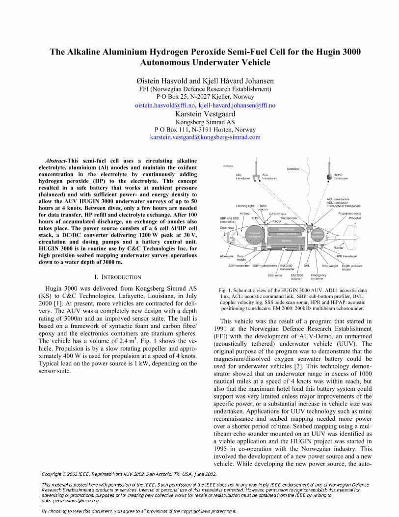
Hugin 3000 was delivered from Kongsberg Simrad AS (KS) to C&C Technologies, Lafayette, Louisiana, in July 2000 [1]. At present, more vehicles are contracted for deli-very. The AUV was a completely new design with a depth rating of 3000m and an improved sensor suite. The hull is based on a framework of syntactic foam and carbon fibre/ epoxy and the electronics containers are titanium spheres. The vehicle has a volume of 2.4 m3. Fig. 1 shows the ve-hicle. Propulsion is by a slow rotating propeller and appro-ximately 400 W is used for propulsion at a speed of 4 knots. Typical load on the power source is 1 kW, depending on the sensor suite.
Fig. 1. Schematic view of the HUGIN 3000 AUV. ADL: acoustic data link, ACL: acoustic command link, SBP: sub-bottom profiler, DVL: doppler velocity log, SSS: side scan sonar, HPR and HiPAP: acoustic positioning transducers. EM 2000: 200kHz multibeam echosounder.
This vehicle was the result of a program that started in
1991 at the Norwegian Defence Research Establishment (FFI) with the development of AUV-Demo, an unmanned (acoustically tethered) underwater vehicle (UUV). The original purpose of the program was to demonstrate that the magnesium/dissolved oxygen seawater battery could be used for underwater vehicles [2]. This technology demon-strator showed that an underwater range in excess of 1000 nautical miles at a speed of 4 knots was within reach, but also that the maximum hotel load this battery system could support was very limited unless major improvements of the specific power, or a substantial increase in vehicle size was undertaken. Applications for UUV technology such as mine reconnaissance and seabed mapping needed more power over a shorter period of time. Seabed mapping using a mul-tibeam echo sounder mounted on an UUV was identified as a viable application and the HUGIN project was started in 1995 in co-operation with the Norwegian industry. This involved the development of a new power source and a new vehicle. While developing the new power source, the auto-
89
nomous underwater vehicle (AUV) HUGIN I was designed using conventional NiCd batteries.
HUGIN I was used for the generation of high resolution maps of the seabed. In this application, the AUV cruises below a mother vessel at constant speed and altitude over the seabed with the echo sounder covering a swath of 120º. A typical survey would be a swath width of 170 m at a height of 50 m and a ping rate of 5 Hz. An acoustic posi-tioning system gives the relative position of the AUV to the mother vessel and differential GPS (DGPS) gives the abso-lute position of the mother vessel in global coordinates. Other sensors are used to compensate for orientations and accelerations of the two vessels making it possible to gene-rate seabed maps with very high accuracy and resolution. The cost of mapping is very dependent on vehicle speed, giving platforms that do not need to drag a cable through the water, a great advantage in deep water. In addition, the stability of the untethered platform is much better.
Because of FFI‘s extensive knowledge of the Al/Air system from our earlier work [3,4,5], we initially evaluated the alkaline aluminium/oxygen (gas) system for AUV appli-cation. Power- and energy density of this system is high, but the system is complex and the formation of hydrogen from aluminium corrosion in presence of oxygen must be handled properly. We also found that a system with gas electrodes is most easily handled at constant pressure, thus it should be contained in a pressure resistant container.
Storage of oxygen in a large vehicle can be made very weight efficient using liquid oxygen, but as the vehicle gets smaller, the relative weight and volume of the thermal insu-lation increase, making compressed gas more favourable. Using state of the art composite containers, approximately 50% of the system weight can be oxygen, compared to typi-cally 20% with 300 bar metal gas bottles. The density of oxygen at 300 Bar is 400 kg/m3. An alternative to the use of compressed gas is to store oxygen as a compound, which can be easily decomposed to liberate oxygen. Decomposi-tion of hydrogen peroxide liberates 0.471 kg of oxygen per kg HP:
2 H2O2 = 2 H2O + O2 (1)
Because concentrated HP is unstable and the reaction (1)
is very exothermic, pure HP is seldom used. Commercial HP solutions also contain inhibitors of decomposition. 50% and 70% HP are in routine use by the industry and higher concentrations have been used in torpedoes in the Scandi-navian countries for many years without accidents. The first known patent on the Al/HP system belongs to Zaromb [6] An alkaline Al/O2 battery based on HP decomposition for O2 supply has been published by Alupower [7] and work on the Al/HP system is also underway at the Naval Underwater Warfare System Center in Newport [8,9]. A cathode based on a combination of HP and sulphuric acid is under deve-lopment for magnesium/seawater batteries [10].
If a battery contains only solid or liquid components, change of volume with increasing pressure is small, making the operation of the battery independent of the ambient pressure. Thus pressure tolerant designs (“pressure ba-lanced”) are very useful for deep diving vehicles [11]. As the weight of a pressure hull increases with its design depth and as the vehicles mass in water should be equal to its displacement for neutral buoyancy, the ability to bring energy and instrumentation inside the pressure hull de-creases with increasing design depth. By placing the battery outside the pressure hull, only the weight of the battery in water must be compensated.
To use this concept with the alkaline aluminium system requires oxygen or hydrogen peroxide to be dissolved in the electrolyte. One advantage of HP over oxygen gas in am-bient pressure batteries and fuel cells, is that HP can be stored in a plastic bag at ambient pressure and be added to the electrolyte by a simple metering pump. In contrast, oxy-gen from gas bottles must be delivered against the ambient pressure. This work increases with depth and with decreas-ing oxygen pressure in the tank. For a deep dive, such as to 3000 m, the water pressure is 300 bar and the amount of energy required to take the oxygen out of the gas bottle will be quite significant.
HUGIN I has a depth rating of 600 m and was originally equipped with a 3 kWh sealed NiCd battery allowing up to 6 hours under water. This UUV is still in use for system development. The NiCd battery was exchanged by a LiIon battery in 1998 to allow for a larger sensor suite. The next AUV, HUGIN II, was equipped with the first Al/HP battery allowing up to 36 hours endurance under water [12]. This AUV was delivered to Norwegian Underwater Intervention AS (NUI) in the summer 1998 for commercial operation on the Norwegian continental shelf [13].
II. CELL CHEMISTRY
The overall cell reaction in the alkaline Al/HP cell is: 2 Al + 3 H2O2 + 2 OH- = 2 Al(OH)4
- (2)
Whether HP is reduced directly at the cathode according to: 3 H2O2 + 6 e- = 6 OH- (3) or is decomposed at the cathode surface or in the electrolyte according to 3 H2O2 = 3/2 O2 +3 H2O (4a) followed by reduction of oxygen: 3/2 O2 +3 H2O + 6 e- = 6 OH- (4b) does not affect the overall cell reaction.
90
We observed that the direct corrosion reaction of HP with Al according to (2) is rapid and that the rate increases rapid-ly with the concentration of HP in the electrolyte. It also in-creases with the surface area of the anode and with the velocity of the electrolyte over the anode surface. Because of the large negative enthalpy of this reaction, heating of the electrolyte takes place. This will also be the case for the direct reaction of aluminium with oxygen dissolved in the electrolyte:
2 Al + 3/2 O2 + 2 OH- = 2 Al(OH)4
- (5)
Together, the loss of aluminium through the direct reac-tion with oxidant according to reactions (2) and (5), loss of aluminium through reaction with water: 2 Al + 3 H2O + 2 OH- = 2 Al(OH)4
- + 3 H2 (6) and loss of oxygen gas to the surroundings, have a large im-pact on the practical performance of the alkaline Al/HP system. In absence of losses, the production of 1F (26.8Ah) consumes 9g Al, 17 g 50% H2O2 and 62 g 7 M KOH. This corresponds to 305 Ah / kg.
III. THE POWER SOURCE
The power source in HUGIN 3000 is similar in principle to the semi-fuel cell used in HUGIN II [12] but has been improved with respect to power output, pressure rating and efficiency in terms of energy production relative to the con-sumption of reactants. It uses the common circulating electrolyte concept and HP is added directly to the electro-lyte. The cell is made from one row of 28 aluminium anodes sandwiched between two rows of carbon fibre bottle-brush cathodes [14]. The use of bottle-brush cathodes allows for operating the cell at very low concentration of oxygen and HP in the electrolyte, thus keeping losses of aluminium and oxidant low. The electrolyte has constant volume and ex-cess electrolyte and gas is ventilated to the surroundings after mixing with seawater.
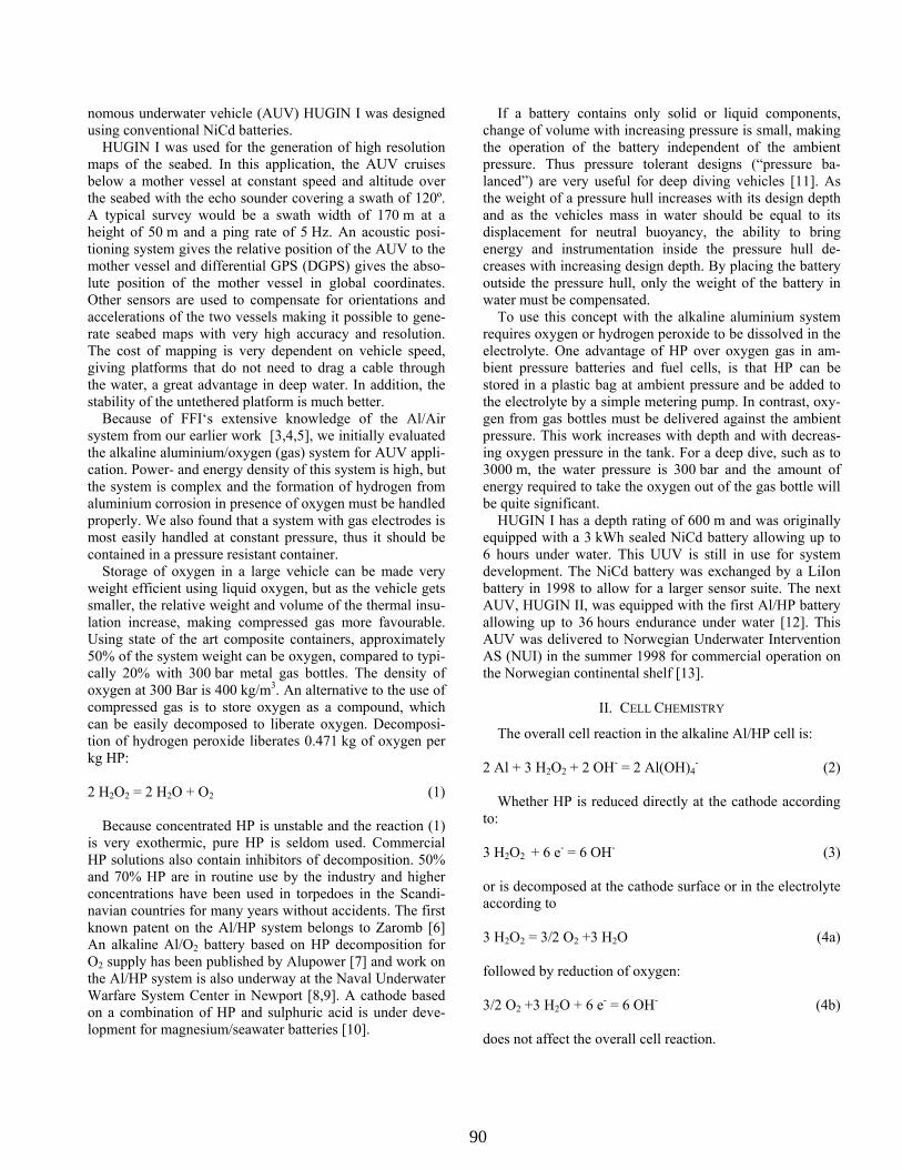
The complete power source consists of the following parts: • Battery box with 6 serially connected cells • Gas ventilation system • Electrolyte circulation system (serial flow) • Two HP storage bags • HP dosing pumps • Battery control electronics • DC/DC converter • NiCd buffer battery (21 F-cells NiCd of 7Ah)
Fig. 2 shows the simplified schematic. Stack current, tem-perature, seawater pressure and cell voltages are monitored continuously and the data used to control the HP dosing and electrolyte circulation pumps.
Fig. 2. The HUGIN 3000 power source.
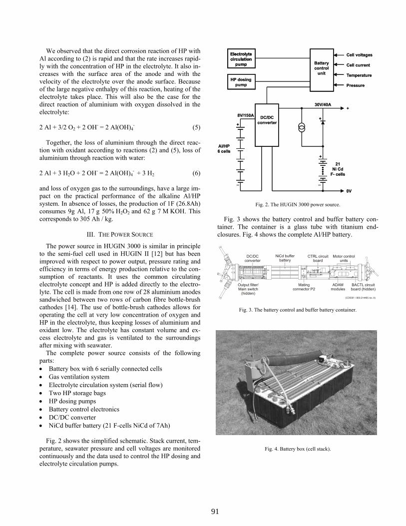
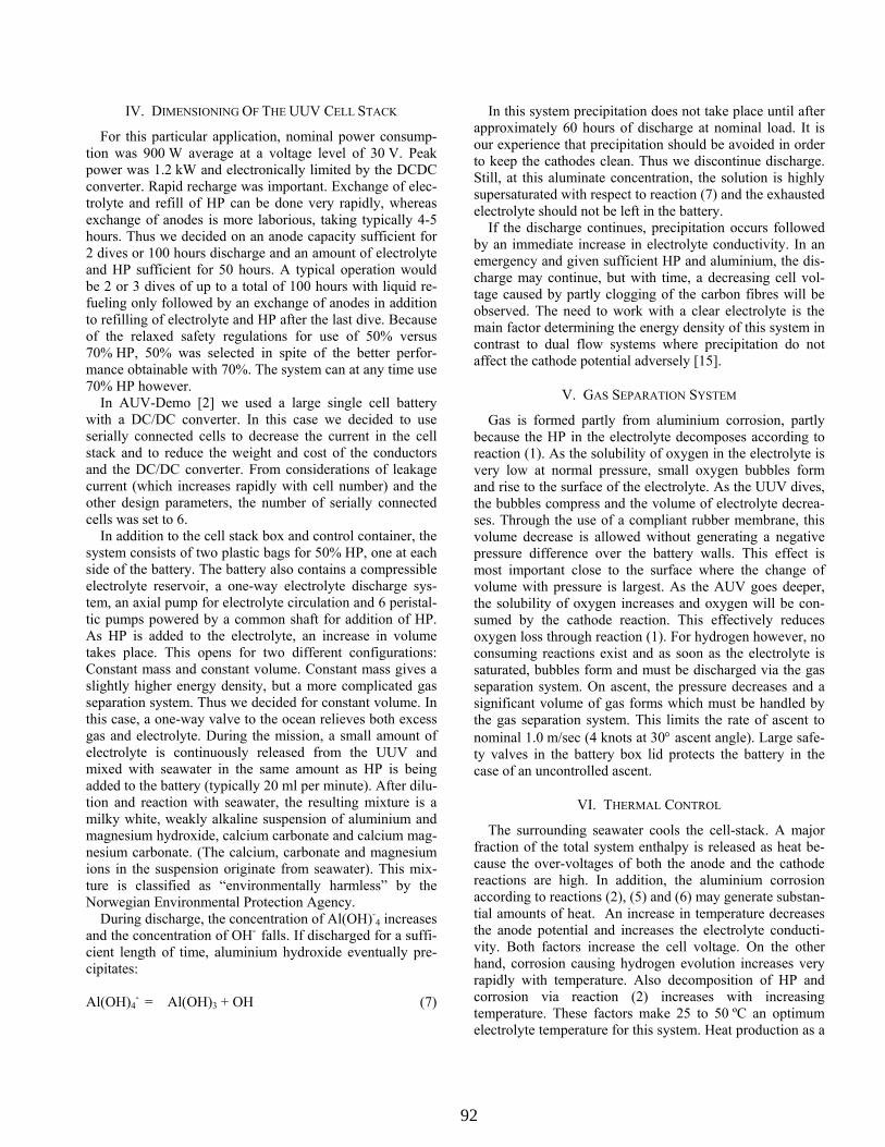
Fig. 3 shows the battery control and buffer battery con-tainer. The container is a glass tube with titanium end-closures. Fig. 4 shows the complete Al/HP battery.
Fig. 3. The battery control and buffer battery container.
Fig. 4. Battery box (cell stack).
Batterycontrol
unit
Electrolytecirculation
pump
HP dosingpump
Cell voltages
Cell current
Temperature
Pressure
DC/DCconverter
8V/150A
+
AI/HP6 cells
_
30V/40A+
+
+
_
0V
21Ni Cd
F- cells
Batterycontrol
unit
Electrolytecirculation
pump
Electrolytecirculation
pump
HP dosingpump
Cell voltages
Cell current
Temperature
Pressure
DC/DCconverter
8V/150A
+
AI/HP6 cells
_
30V/40A+
+
+
_
0V
21Ni Cd
F- cells
91
IV. DIMENSIONING OF THE UUV CELL STACK
For this particular application, nominal power consump-tion was 900 W average at a voltage level of 30 V. Peak power was 1.2 kW and electronically limited by the DCDC converter. Rapid recharge was important. Exchange of elec-trolyte and refill of HP can be done very rapidly, whereas exchange of anodes is more laborious, taking typically 4-5 hours. Thus we decided on an anode capacity sufficient for 2 dives or 100 hours discharge and an amount of electrolyte and HP sufficient for 50 hours. A typical operation would be 2 or 3 dives of up to a total of 100 hours with liquid re-fueling only followed by an exchange of anodes in addition to refilling of electrolyte and HP after the last dive. Because of the relaxed safety regulations for use of 50% versus 70% HP, 50% was selected in spite of the better perfor-mance obtainable with 70%. The system can at any time use 70% HP however.
In AUV-Demo [2] we used a large single cell battery with a DC/DC converter. In this case we decided to use serially connected cells to decrease the current in the cell stack and to reduce the weight and cost of the conductors and the DC/DC converter. From considerations of leakage current (which increases rapidly with cell number) and the other design parameters, the number of serially connected cells was set to 6.
In addition to the cell stack box and control container, the system consists of two plastic bags for 50% HP, one at each side of the battery. The battery also contains a compressible electrolyte reservoir, a one-way electrolyte discharge sys-tem, an axial pump for electrolyte circulation and 6 peristal-tic pumps powered by a common shaft for addition of HP. As HP is added to the electrolyte, an increase in volume takes place. This opens for two different configurations: Constant mass and constant volume. Constant mass gives a slightly higher energy density, but a more complicated gas separation system. Thus we decided for constant volume. In this case, a one-way valve to the ocean relieves both excess gas and electrolyte. During the mission, a small amount of electrolyte is continuously released from the UUV and mixed with seawater in the same amount as HP is being added to the battery (typically 20 ml per minute). After dilu-tion and reaction with seawater, the resulting mixture is a milky white, weakly alkaline suspension of aluminium and magnesium hydroxide, calcium carbonate and calcium mag-nesium carbonate. (The calcium, carbonate and magnesium ions in the suspension originate from seawater). This mix-ture is classified as “environmentally harmless” by the Norwegian Environmental Protection Agency.
During discharge, the concentration of Al(OH)-4 increases
and the concentration of OH- falls. If discharged for a suffi-cient length of time, aluminium hydroxide eventually pre-cipitates:
Al(OH)4
- = Al(OH)3 + OH (7)
In this system precipitation does not take place until after approximately 60 hours of discharge at nominal load. It is our experience that precipitation should be avoided in order to keep the cathodes clean. Thus we discontinue discharge. Still, at this aluminate concentration, the solution is highly supersaturated with respect to reaction (7) and the exhausted electrolyte should not be left in the battery.
If the discharge continues, precipitation occurs followed by an immediate increase in electrolyte conductivity. In an emergency and given sufficient HP and aluminium, the dis-charge may continue, but with time, a decreasing cell vol-tage caused by partly clogging of the carbon fibres will be observed. The need to work with a clear electrolyte is the main factor determining the energy density of this system in contrast to dual flow systems where precipitation do not affect the cathode potential adversely [15].
V. GAS SEPARATION SYSTEM
Gas is formed partly from aluminium corrosion, partly because the HP in the electrolyte decomposes according to reaction (1). As the solubility of oxygen in the electrolyte is very low at normal pressure, small oxygen bubbles form and rise to the surface of the electrolyte. As the UUV dives, the bubbles compress and the volume of electrolyte decrea-ses. Through the use of a compliant rubber membrane, this volume decrease is allowed without generating a negative pressure difference over the battery walls. This effect is most important close to the surface where the change of volume with pressure is largest. As the AUV goes deeper, the solubility of oxygen increases and oxygen will be con-sumed by the cathode reaction. This effectively reduces oxygen loss through reaction (1). For hydrogen however, no consuming reactions exist and as soon as the electrolyte is saturated, bubbles form and must be discharged via the gas separation system. On ascent, the pressure decreases and a significant volume of gas forms which must be handled by the gas separation system. This limits the rate of ascent to nominal 1.0 m/sec (4 knots at 30° ascent angle). Large safe-ty valves in the battery box lid protects the battery in the case of an uncontrolled ascent.
VI. THERMAL CONTROL
The surrounding seawater cools the cell-stack. A major fraction of the total system enthalpy is released as heat be-cause the over-voltages of both the anode and the cathode reactions are high. In addition, the aluminium corrosion according to reactions (2), (5) and (6) may generate substan-tial amounts of heat. An increase in temperature decreases the anode potential and increases the electrolyte conducti-vity. Both factors increase the cell voltage. On the other hand, corrosion causing hydrogen evolution increases very rapidly with temperature. Also decomposition of HP and corrosion via reaction (2) increases with increasing temperature. These factors make 25 to 50 ºC an optimum electrolyte temperature for this system. Heat production as a
92
function of load and HP excess was calculated from a thermal computer model based on tabulated thermodynamic values for the chemical reactions of interest. Results from these calculations were used to evaluate different methods of electrolyte cooling. A thermal control system based on passive heat flow through the battery case was selected. This mode was verified with a complete battery case built with electrolyte flow and electric heaters and tested immersed in water. At nominal load, the steady state battery temperature will be approximately 25°C above the seawater temperature. Due to the large heat capacity of the battery and the reduced power demand (the propulsion motor is not in use), the AUV can still be operated on board the mother ship for several hours before deployment of the AUV must take place.
VII. WEIGHT AND PERFORMANCE
The main figures for the HUGIN 3000 Al/HP semi-fuel cell is given below:
Aluminium anodes for 6 cells 60.8 kg 185 liter 7M KOH (ρ = 1290*kg/m3) 238.7 kg 70 liter 50% HP ((ρ = 1200*kg/m3) 84 kg Sum active components 383.5 kg Battery box complete with cathodes 82.4 kg HP system 6 kg Sum battery weight 472 kg Nominal system energy 50 kWh Battery weight in water 148 kg Battery control container 27 kg Maximum continuous system power * 1200 W
* Short term much more because of the NiCd buffer battery The battery control container weights 7 kg in water. Tak-
ing the weight of the DC/DC converter and the NiCd buffer into consideration, the total system weight is approximately 500 kg and the corresponding energy density 100 Wh/kg.
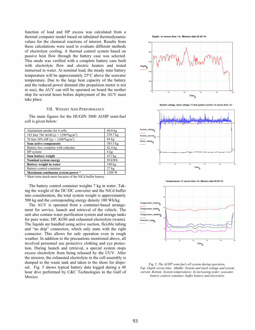
The AUV is operated from a container-based arrange-ment for service, launch and retrieval of the vehicle. The unit also contain water purification system and storage tanks for pure water, HP, KOH and exhausted electrolyte (waste). The liquids are handled using active suction, flexible tubing and “no drip” connectors, which only mate with the right connector. This allows for safe operation even in rough weather. In addition to the precautions mentioned above, all involved personnel use protective clothing and eye protec-tion. During launch and retrieval, a special system stops excess electrolyte from being released by the UUV. After the mission, the exhausted electrolyte in the cell assembly is dumped to the waste tank and taken to the shore for dispo-sal. Fig. 5 shows typical battery data logged during a 48 hour dive performed by C&C Technologies in the Gulf of Mexico.
Depth / m versus time / hr. Mission date 02 04 14:
0 10 20 30 40 500
200
400
600
800
1000
Depthjj
Timejj
System voltage, stack voltage / V and system current / A versus time / hr :
0 10 20 30 40 500
10
20
30
40
System_voltagejj
System_currentjj
Stack_voltagejj
Timejj
Temperatures / C versus time / hr. Mission date 02 04 14:
0 10 20 30 40 500
10
20
30
40
50
Temperature_batteryjj
Temperature_bufferjj
Temperature_ambientjj
Seawater_tempjj
Timejj
Fig. 5. The Al/HP semi-fuel cell system during operation.
Top: Depth versus time. Middle: System and stack voltage and system current. Bottom: System temperatures: In increasing order: seawater,
battery control container, buffer battery and electrolyte
93
VIII. CONCLUSION
The Hugin 3000 UUV has now been operational for 2 years. During 2001 it has operated for more than 5500 nautical miles in water depths down to 2300 m doing con-tracted surveys. More information can be found at C&C Technologies website at http://www.cctechnol.com/ and at http://www.kongsberg-simrad.com/.
Through the operation of the Hugin 3000 AUV it has been demonstrated that this alkaline Al/HP battery system is well suited for deep-sea applications. Initially, the system was rated for 35 kWh, but has recently been upgraded to 50 kWh. At the present level, this alkaline Al/HP power source is unique both in terms of energy density for a neutrally buoyant system and in terms of rate of recharge. With the present amount of aluminium in the battery, simply increasing the amount of electrolyte and HP for a mission may increase the energy available for the AUV during one mission.
ACKNOWLEDGEMENT
C&C Technologies is acknowledged for giving us access to vehicle data and permission to use them in this paper.
REFERENCES [1] T. C. Chance, A. S. Kleiner and J. G. Northcutt (2000). “A high-re-
solution Survey UUV”, Sea Technology, vol. 41 no. 12, December 2000.
[2] Ø. Hasvold (1993). “A Magnesium - Seawater Power Source for Autonomous Underwater Vehicles”, Power Sources 14 (1993), Ed.: A. Attewell and T. Keily, pp. 243-255.
[3] T. Våland, O. Mollestad and G. Nilsson (1981). “Al-Air cells –Potential Small Electric Generators for Field Use”, Power Sources 8 (1981), Ed.: J. Thompson, pp. 523-534.
[4] Ø. Hasvold (1988). “Development of an alkaline aluminium/air bat-tery system”, Chemistry and Industry (1988), pp. 85-88.
[5] N. Størkersen (1991). “Development of a 120W/24V Mechanically Rechargeable Aluminium-Air Battery for Military Applications”, Power Sources 13 (1991), Ed.: T. Keily and B. W. Baxter, pp. 213-224.
[6] S. Zaromb (1980). “Methods and apparatus for generating heat and electrical energy from aluminium”, US Patent 4.198.475.
[7] G. D. Deuchars et al. (1993). “Aluminium- hydrogen peroxide po-wer system for an unmanned underwater vehicle”, Oceans 93, Vancouver, pp. 158-165.
[8] R. R. Besette, J. Cichon and D. W. Dischert (1998). “Performance Optimization of Aluminum-Solution Phase Catholyte Semi Fuel Cells”, Proceedings of the 38th Power Sources Conference 1998, pp. 334-337.
[9] M. G. Medeiros and E. Dow (1998): “Low Rate, Long Endurance Aluminum-Semi Fuel Cells Using a Replenishment Electrolyte Ma-nagement System”, Ibid, pp. 338-341.
[10] M. G. Madeiros, R. R. Bessette, C. M. Deschenes and D. W. Atwater (2001). “Optimization of the magnesium-solution phase catholyte semi-fuel cell for long duration testing”, Journal of Power Sources 96, pp. 236-239.
[11] Ø. Hasvold and N. Størkersen (2001). “Electrochemical power sour-ces for unmanned underwater vehicles used in deep sea survey ope-rations”, Journal of Power Sources 96, pp.252-258.
[12] Ø. Hasvold, K. H. Johansen, O. Mollestad and N. Størkersen (1999). ”The alkaline aluminium / hydrogen peroxide power source in the HUGIN II unmanned underwater vehicle”, Journal of Power Sour-ces 80, pp. 254-260.
[13] Størkersen N, Kristensen K, Indreeide A, Seim J and Glancy T (1998): “Hugin - UUV for Seabed Surveying”. Sea Technology Vol 39 no 2 (1998), pp 99 - 104
[14] Ø. Hasvold (1997). “Batterisystem”, Norwegian Patent NO 304538, PCT /NO98/00309.
[15] C. L. Marsh, S. L. Lich and D. E. Matthews (l995). “Dual flow alu-minium hydrogen peroxide battery”, US Pat 5.445.905.
Keywords: Aluminium anode, hydrogen peroxide ca-thode, alkaline electrolyte semi-fuel cells, aluminium hydro-gen-peroxide batteries,
94


![Electrochemical reduction of hydrogen peroxide on SIMFUEL ......amorphization and decomposition [32]. Although neutral to slightly alkaline conditions (pH 6–9.5) are expected to](https://img.pdfslide.us/doc/110x75/60f691a589db74567b7b1496/electrochemical-reduction-of-hydrogen-peroxide-on-simfuel-amorphization.jpg)