Embed Size (px)
Citation preview
_------------1 GEARDESI'GNII. •
The Alignment ofHigh Speed Gears
SynopsisThis paper reviews the necessity for
detailed specification. design and manu-facture to achieve required performancein service. The precise definition of dutyraring and a thorough understanding ofthe environmental conditions. whether itis in a marine or industrial application. is
required to predict reliable performanceof a gearbox through its service life. Acase study relating to complex marinegear and other general practice is pre-ented to review the techniques used 'by
Allen Gears to design and develop agearbox that integrates with the require-ments of the whole machinery installa-tion. Allen Gears has considerable expe-rience in the design of a variety of indus-trial and marine gears (Ref. I. 2). Therequirements of different type of instal-lations are reviewed to study the impli-cations on gear alignment, Particular
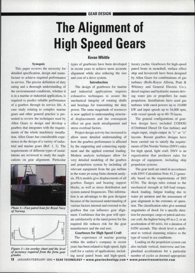
Photo J-Fast patrol boat Jor Royal Nav)',a/alWay.
types of gearboxes have been developedin recent year to achieve more accurmealignment while also reducing the sizeand cost of a drive system.
IntroductionThe design of gearboxesfor marine
and industrial application requiresexhaustive techniques to as ure themechanical integrity of rotating haftand bearings for transmitting the dutypower. Tbe same magnitude of resourcesis now applied to understanding. tructur-al displacements and the consequenteffect on gear mesh misalignment andstress overload factors.
Project. design activity has increased 10
allow more detailed understanding ofhow the gearbox performance is affectedby the supporting and connecting equip-ment and the applied external loading.Modern analysis techniques allow forvery detailed modeling of the gearboxand propulsion system by including allrelevant equipment from the gas turbineto the water jet using finite element analy-is. FEA models give dis pi acements ofall
gearbox flanges and bearing supportblocks. as well a tres distribution andsystem natural frequencies. This informa-
luxury yachts. Gearboxes for high- peedpatrol boat in monohull, surface effectship and hovercraft have been de ignedby Allen Gear for combinations of gasturbines (Rolls-Royce Allison, Pratt &Whitney and General Electric Co.),diesel engine and hydraulic motors driv-ing water jet or propellers for mainpropulsion. Installation have used gasturbines with rated powers up to 10,000
kW andinput speeds lip to 16.000 rpm.with ves el speeds lip 10 60-70 knot .
The general configuration of gear-box deign have included CODOG(COmbined Die el. Or Gas turbine) andsingle-input, single-output ill "c" or ..z..layout. Recent gearbox designs havebeen carried out to satisfy (he require-ment of Del Norske Veritas (ONV) rulesfor high speed. tight craft, DNV is anorganization that produces rules fordesign of equipmeat, including hip
propulsion systems.The gear teeth are rated in accordance
with DNV Calculation ote 41.2 (gener-ally based on the requirements of ISO6336). The design rules extend to themechanical strength at full-load torque.shock loading. fatigue loading due to
lion is an advantage to. the gear de igner water jet aeration and the as . menl ofbecause of the increased understanding ofvarious factors internal and external to thegearbox tilat can jntluence gear align-ment. Confidence that the gear will oper-
ale atisfactorily at the rated power for therequired life reduce Ii k for the gearmanufacturer and the end user,
Gearboxes for High Speed CraftThe experience of marine gearing
gear alignment in the extremes of opera-Don. The classification rules give nominalmagnitudes of shock for a specific dum-tion for passenger. cargo or patrol-and-re -cue craft. the highest being 69 rn.s-2. or anacceleration of 60 m/sJ , for a duration of0.050 seconds. This shock level is attrib-uted to vertical lamming relative to thetype of ve el in ea condsions.
Loading on lite propulsion system Ca._IIwithin (he author's company in recentyears has been related 10 high- peed, lighl also include vertical, transverse and Ion-
Figllre l-An overlay cilart' and thetevei ft Ior avari f ~.. . I d . -. - ~. fofacc14racy required from the form gear era t 10]' a variety 0 applications, me u - gitudmal accelerations nr a particulargrinder.ing naval patrol boats and high-speed, I number of cycles as deemed appropriate18 JANUARYffEBRUARY2003. G,EAR TE,IiH,NOUI'G'I!' • Iwww.gearlecbnology.com '. www.p'owertTansmission.,r;om

_------------1 Gf~RDESmN 11 ._(0 the design of a. vessel.
Gear Design am)1 Alwgnmentaval marine gearboxes are generally
designed to be lightweight while havingonerou requirements for optimizingtoolh loading and gear alignment. U isnot proposed to gi e extensive derails of'the design of such a gearbox. but to givean overview and discllss areas thnt influ-ence gear tooth alignment.
A general contiguranonuses an aJu-mi'nium-fab.ricated gearca e with hori-zontal and vertical joints 10 allow forease of separation and support lines ofgas turbin input, intermediate shafts. idieselinputand water jet output haft" I
iThe gearshatt can be supported by a I
combinauon of rolling element and ihydrodynamic bearings. both of which!can be designed [0 provide a means of iadju l:ing gear alignment. The CODOG igearboxes have automatic changeover ifrom gas turbine to diesel drive. which iachieved by elf-synchronizing clutchesand a multiplaie clutch with two-stagepres ure engagement (Ref. 3), The gear-boxes de igned for the e applicationsgenerally hove integral lubricating oilsYlolems and become complex w.ith theextern of pipework, pumping. coolingand coneol hardware to satisfy spacere trictions.
Gear elements are designed and man-ufaerured in either ca e-carbunzed orgas-nitrided steels for the primary and
alignment occurring in tile same direc-tion for an loading case . The econdeorreeti n is crowning. which will takeaccount of tho e mi alignment that cancause tooth overload. m either end of theface width.
Once these Jongirudlnel correctionhave been establi hed, they are com-bined with any end relief and u ed to cal-culate a set of coordinate alue th i aresuitable for input to the' computer-con-trolled form gear grinder. This ensuresminimal deviation from the design inlenlto that manufactured and removes an ele-m nl of PO" ible influence on gear align-ment. An example of the overlay chartand (he accuracy required is shown in
Figure 2:.....,4. gentmt;"· elevtuion !Viewof tile prtJplI/sio" SI .tem.dictions of structural displacements are lion are applied to the teeth at each mesh\I ed iln the design of gear tooth grinding in the gearbox. One is a fixed change ofreliefs. As staled. the magnitude of distor- helix angle. "torsional correction .... tolions can be predicted by finite element take account of the fixed amount of nus-modeling ofthe gearcase a sembly, withloads applie-d [0 represent the full range ofoperating conditions. The predictedmovements of gear-shaft. bearing hous-ings can be directly related to gear align-ment, and helix-angle corrections tan becalculated,
he finite element analysis of thegearbox. and support sy tern i carried outfor a number of combination of the load-ling condition . At one end of the rangewould be elf-weight plu tran minedtorque, while at the other end would bethese two cases plus. all the maximum. eaconditions. including slamming. Thisensure the gearcase and support systemare ubjected to the range of loading like-
secondary reduction-gear meshes. A Iy 1.0 be e perienced under ervke condi-review of a particular gearbox ill provid- tions,
. . I
ed later wherelhe gears have been From each of the loading cases. the
IiIiiIiii Engineerim; {I.\" {/ design ellgi-
teeth and hence premature failure in these irJeef 011 sublllllrille maini propulsion gear/fig, l,erfomringi design studies ami ll/pponing
In order 10 reduce the e high over- ! georboxes Oil lesl and ill sen'-~ I
of high-speed and loaded gears. the pre- loads. two forms of longitudinal correc- i ice wilh lire Roya! Navy.www.po'wer',.ansmission.com. www ..gBllrtecllll0/ogy ..com • IGIEAIR IEC'IINDlDGY .•. JANUARY/FEBR,lJARV 2003, 1'9
designed 10 DNV rules •.and a number 0:1"
specific observations will be presented.relating to lhh proce: s, Rating of thgear teeth to D V complies with limitthat Allen Gears ha e hi [oricaIly speei-fied in term of urface load and specifibending. but with ome exceptions. Themain difference eb erved u ing DNV isin 'the cuffing capacity and the require-men! for a greater effective ca e depth (at400 HV) than would be required whenrating a nitrided gear to other rule.
As is common with all manufacturers
gearcase deflections at all of the bearingposition' are extracted from the finite ele-ment result, From these deflections, theslope of each shaft line along the line ofaction of each gear mesh is established.These slope values indicate the misalign-ment due to loading of each mesh withinthe gearbox. Without helix modification(0 the gear teeth. the e misalignments willcause hlgh overloads at the ends of the
areas.
IKevanWhittle,is chie] engineer {I/ AllenGears, wi/hill lire industria!business section of Rolls-Royce, mOmlKifll( Ihe produc;dl'sign GIld developmen: oj lowand 1,lg/. spud gearboxes forindustrial and morineapplica-lions. IVlrillie is a charteredmechanical ef'gllJeer trainedwilli fatal! LJd. s transmissiondivision. .tli: tater worked/orIr,ckers SlJiplmildirlg and

GEAR DESIGN: _
Figure 1. The capability of the form
grinding machine tool gives the great-
est possible control to minimize manu-
facturing error, with a process capableof machine-grinding to master gear
quality and helix alignment. of around
0.005 mm.General industrial gears are manufac-
tured to ISO 1328 Grade 4 with machine
adjustments being made to keep profileand helix errors Within specified toler-
ances, Allen gears are manufactured toISO 1328 Grade 4 (AGMA Grade 12).
The alignment of the teeth is set by
initially meshing the gear element in thegear case while supported by accurately
machined low-clearance bearings and
then grinding the gear teeth to have con-forming helix angles. This sets the staticgear alignment and correct for any errors
resulting from the manufacture of thegears, case and bearings.
AJW Systems Co. announces that it is now amanufacturing souroect spiral gear roughingand finishing cutters and bodies.
I We also can manufacture new spiral;, cutter bodies in diameters of 5" through 12"I at present.I .I AIW can also supply rou~hing and finishing
cutters for most 5"-12" diameter bodies.
Whether it's service' or manufacturing, con-sider us as an alternative source, for cuttersand bodies.You'll be in for a pleasant. surprise.
NEWI! Hob and Shaper 'Cutter Resharpeningis now available at AI'N Systems 'Company Royal Oak, Michigan 48067
"fel: (248) 544-3852· Fax: (248) 544·3922
is considered that, to get the best indica-201 JANUARY/FEBRUARY .2003 • G,EAR TECllNOLIOIG'Ir' • www.ge.artechno.logy.c,o.m- www.poweTtr.ansmissio'n.,com
Static alignment is verified by rotat-
ing the gears slowly and visually observ-
ing tile contact pattern between the
meshing teeth. Proof of the mesh isobtained by witnessing the contact mark-ings resulting from blue lacquer trans-
ferred from pinion to wheel, the thick-
ness of lacquer being around O.f}{}3 mm.The gear tooth reliefs are subsequent-
ly applied and include end relief, helix-
angle correction, and crowning. A staticm.isatignment is con equendy introducedin the gear mesh but ensures that, when
operating at full power, the teeth will bealigned and within design limits,
Mounting System. andFEA Model,
The drive configuration and modelisof a gearbox, gas turbine, gas turbineenclosure, support frame and resilient
shock mounts. The model 'of the propul-sion package included the connections
between the support frame and the hull1 mounting point, which spanned orne
four separate lateral bulkhead structuresmanufactured from a sandwich compos-ite material. A sandwich composite con-
sists of two glass-reinforced plastic(GRP) plates wi,th a compound "sand-wiched" in between. Detailed finite ele-
ment modeling of the system wouldprove the integrity of the propulsion sys-
tem under severe load conditions expect-ed at sea. A general elevation view of me
machinery is shown in Figure 2.
A model can be created 'using, forexample, version 5.3 of the ANSYS suite
of software. Elastic straight pipe ele-ments and 3-D beam elements are com-
bined to create the gearcase, or the struc-
ture that holds the gears and bearings inplace, a well a to develop shafts andsystem connections. To correctly modelthe total mass at a particular center ofgravity, structural mass elements are
used. The gearbox and gas turbine areballed to the mounting frame while aflexible coupling connects the twoassemblies. In the model, the gearboxand gas turbine are rigidly connected to a
support frame by a system of constraintequations, the frame being a combinationof four-and eight-node shellelement . It
.. -- IGEAR DESIIGN _
Modeling work was conducted in par-
allel with the gearbox detail design activ-ity and provided detailed requirements for
methods of upporting the gearcase 10
achieve the necessary alignment of the
gear to the gas turbine, The support of thepropulsion unit was through 1.6 rubbermounts, which were modeled as unidirec-tional nonlinear spring elements to repro-duce the force defl.ection curves speci-
tied. The resilient mount elements had arange of stiffness and dynamic magnifiersto allow the support frame to deflect in acontrolled manner.
Analysis of the propul ion systemmodel gave the following outputs:
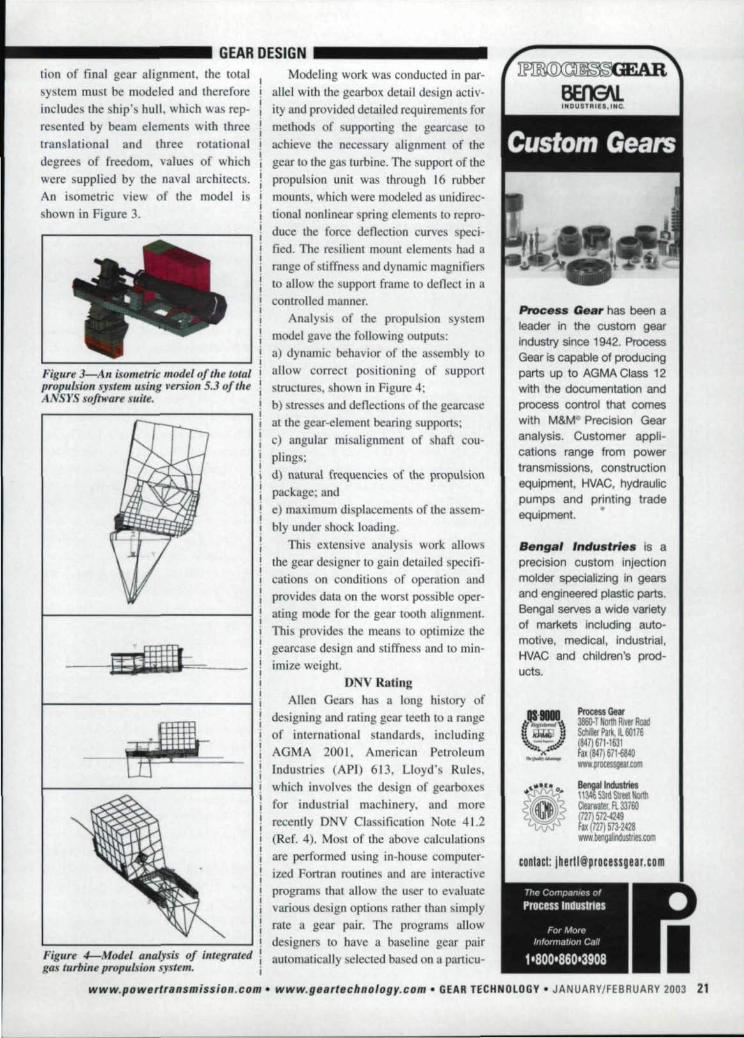
la) dynamic behavior of the assembly toL..- ---::....- ---JI i1 allow correct positioning of supportii structures, shown in Figure 4;i b) stresses and deflection of the gearcase~--------------------,I !I 1 at ihe gear-element bearing supports;
I !~ c) angular misalignment of haft cou-plings;
d) natural frequencies of the propulsionpackage; and
'e) maximum displacement of the assem-blyunder hock loading,
This extensive analysis work allowsthe gear de igner to gain detailed specifi-calion on condition of operation andprovides data on the wor t po sible oper-ating mode for the gear tooth alignmentThi provide the means to optimize thegearca e design and stiffness and to min-imize weight.
DNV RatingAllen Gears has a long history of
designing and rating gear teeth to a rangeof international standards, including
AGMA 2001, American PetroleumIndustrie (API) 613, Lloyd's Rules,
which involvesthe de ign of gearboxesfor industrial machinery, and more
recently !DNV Classification Note 41.2(Ref. 4). Most of the above calculations
areperforrned using in-house computer-
ized Fortran routines and are interactiveprograms that allow the user to evaluatevarious design options rather than simplyrate a gear pair. The programs allowdesigners to have a baseline gear pairautomatically selected ba ed on II parricu-
lioll of final gear alignment the total
system must be modeled and thereforeincludes the ship's hull, which was rep-
resented by beam elements with threetranslational and three rotational
degrees of freedom, value of whichwere supplied by the naval. architects.
An isometric view of the model is
shown in Figure 3.
Figure 3---,.4n isomemc model of tile totalp.~opl~ls.iollsystem using persian 5.3 ,of tll,eA SYS .sofh!.tarl!suite.
F,igure4-Model ,analysis of ,integratedgas tu.riJine propulsion sys.tem •.
PrDce8s 'G_ ar has been aleader in the custom gearindustry slnoe194.2. ProcessGear is capable of prodUCingparts up to AGMA Class 12with tlie documentation andprocess control tliat comeswith M&MO Precision Gearanalysls. Customer appli-cations range from powertransmissions, constructionequipment, HVAC, hydraulicpumpsandl printing trade~equipment.
Senga' Industries is aprecision custom injectionmolder speciali~ing In gearsand ,engineered plastic parts.lBengal serves a wide varietyof markets including auto-motive, medical, industrial,HVAC and children's prod-
I ucts.
Process Gear3860- T Nortn Rrm RoadSchiller Park, IL 60176(847) 671-1631Fax (847) 671·6840WIIW.processgear.com
Bengal' IndIIslrIes11~ 531\1S\!m HIlnhClearwater, FL 33160(7)572-4249hx r27J 573·2428WIIW.bengalindustri6.oom
www.powetttansmission.,com- www.geartechno'lo'gy.co'm. IGEA!R JECHN'IlLIlGiV •. JANUAAY/FE,BAUAAY 2003211

... --- GEAR DESIG,N
lar input power, speed, ratio, etc. Also,the programs give options to change anyfeature and have remaining featuresrecalculated instantly. The programs cal-culate the gear service factors and data to
define the salient points of the gearboxdesign that are suitable for supplying to acustomer and to create manufacturingdrawings.
DNV rating of gear teeth allows forfinite and infinite life assessments of agear pair for one or more load cases andgives service factors for contact, bendingand scuffing resistance. As previously dis-cussed, there are a number of points that
l000~------------------------'950900850
_800~750-;;700~650-2600~550
5004504003503000L--O.-12-5--0-.2-5-0-.3-7-5-0-.5---0.6-2-5--0.7-5--0.8~75
Case Depth {mm)
Chrome, Molybdenum
~ Chrome,Molybdenum,Vanadium
Figure 5-The difference between actualcase depth profile fora 3% chromium-11IoiybdelJU11Initriding steel and a J.4%chrome-molybdenllm-Valladium steel.
nitrided gears. Scuffing assessments forflash and bulk.temperatures' tooth overloadfactors, which relates to the prediction ofscuffing between two meshing gears alsoshould be looked into further.
The size factor Zr is particularly oner-ous for the rating of nitrided gears.Nitrided gear tooth permissible stressescan be reduced by approximately 40%
when
Zr= (30t 400
Pc )0.4--::-:1.=20..,..,0__
OJ Hlim
are worthy of further discussion, including Suitable materials exist that produce a difficult to procure oils with the requiredcalculation of case depth "size factor" for case depth versus hardness curve that FZG capacity. Allen Gears have specific
minimizes the effect of this penalty to rules on allowable flash temperaturesaround 30%. However, it is not AllenGears' experience that nitrided gears havesuch a poor surface fatigue strength.
Comparisons of the actual case depthprofile for a 3% chromium-molybdenumnitriding steel and a 1.4% chrome-molyb-denum-vanadium steel is shown in Figure5 to demonstrate the increased depthachieved at 0.7 mm at 400 HY. Undermost circumstances, the designer wouldendeavor to choose carburizing steelswhere the case depths achieved easilyproduce a factor Zx = 1. This does, how-
ever. introduce limitations on the con-struction of large gear wheels a:nd com-promise the objective of lightweight COn-
struction.Scuffing assessment to DNV consists
of integral and flash temperature caIcu.la-tions, To achieve satisfactory safety mar-gins, the specified oil load carryingcapacity must be around. FZG 12. To stopasperity contact, the oils must provide afiLmthickness between two gear flanks.
Oils with a low load capacity are like-ly to suffer from pitting and scuffing.With mineral oils having a viscositygrade of ISO VO 32 or 46, it becomes
and have had virtually no. failuresthrough scuffing. The requirements ofDNV are onerous and make Allen Gears'current limits and practice unacceptable.
Alignment of Industrial GearboxesAlignment of gear teeth and the
resulting overloads across the gear facewidths in parallel shaft gears is con-trolled by the structural integrity.Loading on input and output shaft bear-ings is influenced by the stiffness andalignment capability of the connectingshafts and coupLings, and the modelingwork carried out on marine gears is vitalto verify the integrity of the high speedcouplings and also to prevent limitsbeing exceeded on the connecting equip-ment's shaft bearings. The particularcase study discussed in this paper used amembrane coupling with a length of 870mm and had finite limits on axial, lateraland angular misalignment The FEAmodel confirmed that these would not beexceeded in service.
The requirement to accurately alignthe gearbox to connecting equipment iskey to satisfying gear tooth alignmentand is more critical on some epicyclicgear products depending on couplingdesign features. The general configura-tion of a single-reduction star arrange-ment is shown in Figure 6. The gear clus-
Figure 6-Tlle general configuratiol' of a single-reduction star arrangement in an ter can be configured into a range ofepicyclic gear product. gearcases to provide free-standing,22 JANUARY/FEBRUARY 2003 • GiEAR TECHNOLOGY. www.geartec.hllology.c.om- www.powertrslIsmissioll.com

_------- GIEAR:IDESI'GINI _
engine-mounted or generator-mounted
arrangements.
Figure 6 show the generator-mounted
gearbox where alignment of the gears isobtained by accurately locating the gearonto the driven (generator) shaft. Thi pro-
vide benefi ts in the package efficiencywhere there are no low-speed haft bear-
ings and benefits by reducing the gearboxlength. cost and weight. Alignmenl of theinput and output shafts is critical to controlmisahgnmem of the gear teeth and isachieved by accurate machining. assembly
and measurement duri ng the installationprocedure. Any errors in alignment of thegearease when attached 10 !he generatorwill transfer through to the high-peedshafl via the gear mesh,
Accurate high-speed shaft alignment
wa traditionally achieved by manualmethods using dial indicators. and theprocess could lake approximately 24hour. Indications would be that. tbeequipment was in alignment. but the set-
ting was carried out with a gearbox hav-ing no installed gears or bearing . Thedial dock was filled to [he driven (out-
puu equipment shaft and then checked to \the gearcase driver (inpul) end and
adjustments made. Consequently, whenthe gears were fitled, an alignment error
was introduced due to ihe additional
overhung rna .Current techniques allow the equip-
ment to be aligned in eight hours u ingelectronic methods. Displacement probes
can be fitted tothe fully assembled gear-box. The gearbox is then driven, with out-puts from the probe being processed by apersonal computer to calculate misalign-
ment and any necessary adjustments.The customer support team within
Allen Gears is regularly involved in theinstallation of gears and have a directcontribution to gearboxes in a variety ofapplications. from large water turbines 10
small higlil-ga turbines. In marinepropulsion. the technology for aligningparallel-shaf gears and couplings haadvanced in recent. years with the use of
laser alignment. which is accurate 10
0.002 mm across distances of 5 m.
Concluding RemarksComplex gearcases and shaft arrange-
ments can now be designed and analyzed
using FEAlechniques to gain greater assur-ances on the safe performance of the sys-
tem under load. Industrial gearboxes tendto be designed around a general type ofconfiguration where structural integrity is
known and is easily predicted. Also, thedesigns have evolved in recent years to
allow for 'easier installation, and equip-ment/methods have also changed toimprove the accuracy of the installation.
Calculations and predictions of align-ment are critical to tJ1C validation of a gearde ign, and access to information on struc-
tural stiffness is key ro determining the
magnitude of the face overload factor andis easily extracted :Fearn an FEA model.
Customers are demanding this level ofanalysis to lower the ri k associated withmain propulsion gearboxes.
The rating of gear teeth to DNV marinerequiremeats can. in some circumstances.result in a larger gear pairtban would berequired to satisfy other standard .. Currentwork within the British Gear Associationinvolves researching the technology requiredto enhance material and lubrication technolo--gy to enable the optimum design to beobtained and to address thjs problem. 0
RieJere!l(:esI. Yates. D.E. "Epicyclic Gears." RNtEC Manadon,Paper 5, September 1989. Manadon, U.K.2. Yates. D.E. "Epicyclic <Gearing for Ga TurbineMain Propulsion." ASM!E Gas Turbine and FluidsEngineering Conference. New Orlean. LA, March1976.3. Sigg, H. "Marine Gearing=-develcpmenr andtechnology," Thomas Lowe Gray Lecture. 1990.London. U.K.4. Del orske Verita Classification Note 41.2.Calculation of Gear Rating for Marirll!Transmissions. July 1993. DNV. Hovik, Norway.
Tell Us What You Think ...I VIsil WWW~CCD1D
• RaIl dis IIIicIe.1IIMpIst RUe infDnn1IIIion• Contact ..... or~memonad• Make I suggeslionOr call (847) 437-6604 to talk to one of oureditors!
Now you can fulfill yourgear rack requirements
with one of twoInnovative solutions-Contact 'Us to ma.nufactul'\e yOlJrCustom and :Stock Gear Racks
•. Various Rack Shapes, Sizes /10 Materials•. Unique TOOthConfigurations• Heat Treating• CIlmptele
MachIning• t D.P.-
120 D.P.• 25 module -
0.25 module•. Up to IS'
faGe width• Up to 82' lengths-longer Ihrough ~BS8t1lng
.' ~uracy IOlerances up to AGMII all• Spur. Helical. Relieved, Tapered, Crowned• Prototype and Production Quantities• Breakdown Service AV8liabie• Reverss Engineering capabllil'lWeus:• latest 5a1~unl eNC Rack Milling Technology.• Precision Rack Shapers.• Gear HQbbers /10 Shapers.• tkIrIzonlal & Vertical Macl1iru!lg Centm•. CNC Ver1lcal Machining Centers• Inspection Equipment
---@"l-----Contacl US 10'sen yOIJ
highly-capable machines to,ImanufactlJre 'Gear IRacks.
Safkunl CNCSpur • HelicalGear Ra.ck Milling Machines
.• 5arkunl's NR series with a IoI1g prO'len Irack record• High Power!! High Quality!!• Various eNG Culling Functklns-varlabte pilch.
plunge. relief, crown, taper. e1e.• In additIon to the standard rack milling machine,
Saikuni manufactures special steering rack andbroach cutter milling machlnes,ll!tk g-Mndingmaclllllll1l, and (lther macllil"le'!. related to gearing.
• Visit Se.lkunl's websHe al WNW.salkunl.co.Jp
Calli Zen & Jerry to get to know InnovativeRack & Gear Oompany (IRGeo.) baiter alldallow us to answer your questions aboutus or Saikuni. We look forward to yourrequests for quotes 011 your requirements.
www.powe,rrransm.is.siOfJ'.com • www.gearI8'ch.no#of}y.com • ClEAR TEIC'HNIIUIGY" JANUARV/FEBRUARV 2003 23


![Technical Report 6336 - DiVA portal489751/FULLTEXT01.pdfThe first part, ISO 6336-1 [1], provides the basic principles, an introduction, and general influence factors. ISO 6336-2 [2]](https://img.pdfslide.us/doc/110x75/60c3f6f748dbf461f2776146/technical-report-6336-diva-489751fulltext01pdf-the-first-part-iso-6336-1-1.jpg)