Embed Size (px)
Citation preview

Page1
THEADVANTAGESOFCONTINUOUSMONITORINGOFPOWERLINECARRIER(PLC)CHANNELSAPPLIEDTOPROTECTIONSYSTEMS
RogerRay,AlanJayson&RayFella,PowerCommSolutions,LLC,JeffreyEBrown,Georgia
Transmission;NeilStone&RobertBaldwin,SouthernCaliforniaEdison
INTRODUCTION
Thecriticalnatureofthepowertransmissionsystemtodaymakesitimperativethatutilitieskeepupwiththedemandofroutinemaintenanceoftheprotectionsystem,aswellas,monitoringthehealthofthesystem.Inthismanner,thereliabilityofthesystemcanbeassured.Thispaperwilldescribemethodsbywhichthesystemcanbemonitoredandhowthedatacanbeusedtopredicttheneedformaintenancebeforesystemfailureoccurs.
Todaytheprotectionsystemismadeupofmicroprocessorrelays,whichcanmonitortheirhealthandalarmifthereareproblemswiththesystem.ManyoftheseprotectionsystemsemploytheuseofPower-Line-Carrier(PLC)equipmenttoaidinthesimultaneousdetectionofthefaultatalllineterminalstoclearthefault.ManyofthesePLCsystemsdonotcanmonitorallaspectsoftheirhealth.Also,wehavenothadtheabilityofbeingabletohaveanindependentdevice(suchaswhataDigitalFaultRecorder(DFR)doesforthepowerfrequencyequipment)thatcanmonitortransientresponsesoftheRFportionofthePLCsystem.Ifthistypeofequipmentwereavailable,anyabnormaltransientbehavioroftheterminalequipmentaswellasthecommunicationspathcanbemonitoredandproblemscanbedetectedbeforetheybecomeanissueaffectingthereliabilityoftheprotectionsystem.Inaddition,whenunexpectedsystemeventsoccur,datawillbeavailableforindepthanalysisofthecommunicationpaththatcanbesynchronizedandcomparedtootherdevicesonthesystem.ThisdatacanbeusedtoassistinanalyzingwhatisoccurringontheRFpathwhenaPLCissue(e.g.carrierholes)hasoccurred.
PRC-005-002PowerSystemMaintenanceStandard[4]nowrequiresutilitiestoperformmaintenanceontheirProtectionSystemsatspecificmaximumintervalsbasedonthelevelofmonitoringthatexists.Complyingwiththisrelativelynewstandardcanpotentiallybeverycostlytoautility.ADFRtypeofcontinuousmonitoringsystemforthePLCsystemcoulddrasticallyreducethecostoftheperiodicmaintenance.Informationsuchasreflectedpower,levels,margins,andevensystemnoiseatcarrierfrequencycouldbemaintained.Whenamaintenancecycleapproachesrealtimedatafromthemonitoringsystemwouldbecapturedandcomparedtoarchiveddatatodeterminewhatmaintenance,ifany,isneeded.Thisreal-timemonitoringwillreducesystemdowntimewhileminimizinghumaninteractionwithlivesystemsthatsometimesleadtounexpectedoperationalincidents.
FUNCTIONSIMPORTANTTOAPLCMONITORINGSYSTEM
StandingWaveRatio(%RFLP)/%ReflectedPower%RFLPMonitoring
Monitoring%RFLP/%ReflectedPowerprovidesvaluableinformationtoaPowerLineCarrierprotectionuser.The%RFLPofaPLCsystemisaffectedbychangesinImpedanceterminatingthetransmitter.WhenchangesoccuronthePowerLineCarriersystemtheyaretypicallyacombinationoftheresistive,capacitiveandinductivecomponents.KnowingtheImpedanceandPhaseAngleofthe%RFLPiscriticaltothediagnosisofthesechanges.Havingadevicethatis

Page2
capableofmeasuringboththeimpedanceandphaseanglewiththe%RFLPmeasurementisimportantfortroubleshootingthechange.Anychangesintheseelementsprovidescluestowhatmayhavecausedthechangeinthereflectedpowerreading.Forexample,aPowerLineCarrierMonitoring(PCM)devicelocatedperFigure11withazero%reflectedpowerreadingshouldmeasureanimpedanceof50𝛀withazero-degreephaseangle.
AnincreaseintheimpedanceofthemeasurementmeansthattherewasanincreaseintheimpedanceoftheentirePLCsystem.Anegativephasetellstheuserthattherehasbeenachangethathascausedthesystemtobecomemorecapacitivetothatfrequencyoriftheangleispositivetheimpedancehasbecomeinductive.Someexamplesofwhatthesedetailedmeasurementscanindicatearelinetrapfailures,linetunerproblems,overalllineimpedancechangesforvariationreasons.
Ifonlythemagnitudeorpercentreflectedpowerisknown,thereisnowaytoknowwhatismismatchedorwhatmayhavechangedontheoverallPLCsystem.
Table1showsexamplesthatallrepresenta10%reflectedpowerreading.Notethateachhavesignificantlydifferentresistive,capacitiveandinductivecomponents.Havingtheimpedanceandanglemeasurementsnowprovidesaclearerpathtowhathaschangedintheoverallsystem.
Table1-ImpedancesResulting
ina10%ReflectedPower
Z FAngle
80.75𝛀 +23.95o63.59𝛀 -32.71o39.37𝛀 +32.75o36.68𝛀 -30.94o
PLCReceiverTypeMeasurements
HavingamonitordevicethatreplicatesthecharacteristicsofaPowerLineCarrierreceivernotonlyprovidesasecondwaytodetectproblems,butthisindependentdeviceisnotrestrainedbytheextraprotectionsandtimersneededtomeetthedesiredsecurityanddependability.Anindependentreceiver/monitoringdevicecanbesetmoresensitivetocaptureactualrawmeasurements.Thisiscriticalinformationthattheregularreceivermaysee,butdoesnotreactto,basedonitsschemeand/orindividualprotectivesettings.Amoresensitivedevicecanprovidevaluableearlydetectiontopotentialfutureproblemsbeforetheyoccur.Addinglongtermtrending(hourly/dailymeasurements)forLevelorReflectedpowerenhancestheopportunitytoavoidpossiblemis-operationsinthefuture.TrendingcanalsoprovideinsighttoshorttermeventsthatnegativelyimpacttheCarriersystem,likeadverseweatherconditions.TimeSynchronizationoftheeventrecorderisalsovaluablewhencomparingeventlogsbetweenvariousprotectivedevicesinthesystems.
SpectrumAnalysisUsingFastFourierTransform(FFT)
UsingFFT’s:Withtimedomainviewing(Oscilloscope)itisnotpossibletoseetheindividualsignalyouareinterestedinbecauseitshowsacompositeofallthesignalspresent,includingnoise.Toviewmultiplesignalsatthesametime,usingfrequencydomain(FFT’s)isthebestway.

Page3
Withatime-domaindisplayoneisviewingamplitudeontheYaxisandtimeontheXaxis).WithafrequencydomaindisplayoneisviewingamplitudeontheYaxisandfrequencyontheXaxis.
Thesignalissampled“N”times(totalsamples),atafrequencyhighenoughtoproduceallfrequenciesineachband,andstoredinabuffer.AnFFTisrunonthestoredsamplesandanamplitude/frequencyplotisproduced.AnexampleofatimedomainplotvsafrequencydomainplotisshowninFigure1below.
Figure1-Timedomainvsfrequencydomainplots
EventDrivenFFT’s:
EventdrivenFFT’SprovideanopportunitytoseewhathasoccurredontheRFpathduringaspecificevent.Examplesofsomeoftheseeventsarelossofsignal,receivedguardortrip,%RFLPoutofrange,etc.Thecapturedspectralanalysisprovidesmoreinsighttowhatmayhavehappenedwhenoneofthesespecificeventsisrecorded.Forexample,somelossofguardeventsrecordedbyPLCreceivers,canbecausedbyvariousevents,notjustbythelossoftheactualsignal(Guard).Atransientnoiseeventcancausethesignaltonoiseratiotodecreasesignificantlywhichcouldcausethereceivertoindicatealossofguardeventhoughtheguardfrequencyisstillpresent.
Figure2showsanFFTcaptureofasingleFSKtransmitterinitsnormalstate.Figure3showsacaptureofatransientnoiseeventonthesamelinewiththeguardfrequencystillpresent.NotetheGuardfrequencyisstillpresent,althoughthesignal-to-noiseratioisvisiblyworse.Insomecases,thistypeofeventcancauseareceivertoclamp(notpermitguardortrip),whichcanberecordedbythePLCReceiverorprotectiverelayitstiedasalossofguardevent.AnFFTcaptureofthiseventhelpstheuseridentifythatthetransmitterandreceiverseemtobeoperatingasexpectedandthussavessignificanttimebyeliminatingthetransmitterandreceiverasthecauseoftheproblem.

Page4
Figure2-ExampleofaTransmitterinitsNormalState
Figure3-ExampleofaNoiseEvent
SpectralAnalysisCapturewithOverlay
WhencommissioningaPCMdevice,theabilitytocapturearealtimeSpectralAnalysisoftheChannelcanbeanincrediblyusefultoolinanalyzingchangesorintrusionstotheknownfrequenciesontheline.Areal-timecapturepermitstheusertheabilitytoidentifyallfrequencies,levelsandnoisepresentatthetimeofcommissioningandverifythattheyareknownentitiesandacceptablelevels.Ifthis“commissioning”oracceptablestateSpectralAnalysiscanbesavedasareferenceorbaseline,theusernowhasaninvaluabletoolforfuturesystemanalysisor

Page5
troubleshooting.WhentheuseraccessesthePCMdeviceonalaterdateandcapturesanewSpectralAnalysisofthesameChannelandthenimportstheoriginalcaptureasanoverlay,theycanseeanychangesthatmayhaveoccurred.Figure4showsaninitialRealTimeCaptureofaChannelwith3frequenciespresent.
Figure4-InitialRealTimeCapture
Figure5-InitialCaptureOverlaidwithaLaterCapture
Figure5showsapresentSpectralAnalysisCapturewithanoriginalcaptureoverlaid.Thegreencapturerepresentstheoriginalcaptureandtheyellowrepresentsthepresentcapture.Notethatthenewcapturehasa4thfrequencythatdidnotexistattimeoftheoriginalcapture.
Thisoverlaytoolcanbeusedtoassistandidentifymanypotentialissuesbeforetheybecomeactualproblemsormisoperations.Forexample,whenanymaintenanceornewinstallsareperformedonlyafewbussesawayfromasitebeingmonitored,oftentimefrequenciescanbleedthroughandshowupathighenoughlevelstopotentiallyinterferewithanexistingprotectionchannel.Usingtheoverlayprocessatanytimecaneasilyhelpidentifypotentialproblemsquickly.Thereisalsothepossibilityofdetectinglinetrapfailuressimplybecauseanewfrequencyhasappearedinthepresentrealtimespectralanalysiscapturethatoncedidnotexist.Knowingthatunexpected

Page6
frequencyvaluepermitsausertheabilitytoidentifywhereintheirsystemthatfrequencymaybecomingfrom.
LongTermMonitoring–MaintenanceExtension–AssistwithNERCCompliance
APCMinstalledpermanentlyprovidestheutilityamechanismthatcanbeusedtomoreeasilycomplywithPRC-005-002maintenancecycles,butcanalsoreducecosts.Inaddition,onceinstalled,thePCMcanbeaccessedatanytimeeitherremotelyorlocallytoreviewmeasurementswithouttheneedforaPLCsystemoutage.ApermanentlyinstalledPCMdeviceislikehavingmultipleinstrumentsinthesystemalways.ThePCMcanbeusedtorecord“AsLeftData”atcommissioningoratanyfuturetime.This“AsLeft”datarepresentsthepresentmeasurementsofthePLCchannelsandwhenconnectedtoasatelliteclockcanrepresentamaintenancetest.ThisAsLeftreadingcannotonlybeusedformaintenancetesting,butalsobecomesapermanentelectronichistoryofallmaintenancemeasurementsperformedwithtimeanddatestamp.
APPLICATIONOFAMONITORTOTHEPLCSYSTEM
HowLocationofthereflectedPowerMeasurementAffectstheResults
BeforeadiscussionabouttheapplicationofamonitortoaPLCsystem,itisimportanttoknowhowthelocationwherethe%RFLPismeasuredwillaffectthereading.Itiswidelyacceptedthatthebestlocationtoperform%RFLPmeasurementsisattheRFinputofthelinetuner.Whenadditionalcomponentslikehybridsareinsertedintothepathbetweenthe%RFLPmeasurementandthetuner,thereadingswillnotbethesame.Commonlocationsfor%RFLPmeasurementscanbeseeninFigure6&Figure7.
Figure6-%RFLPVariationBetweenLocation1&2
Figure7--%RFLPVariationBetweenLocation1&3
Figure8shows%RFLPmeasurementsmadeatbothlocations1&2,withtheImpedanceconstantat50𝛀andavariablephaseangle.

Page7
Figure8-%RFLPDifferencesBetweenLocations1&2:
ImpedanceFixedat50𝛀:VariableAngle
Priortothehavingtheabilitytomeasurethephaseanglecomponentofa%RFLPmeasurement,itwasnotpossibletoknowhowacapacitiveorinductivechangetotheCarriersystemwouldaffectreadingsatdifferentlocationsinthecircuit.ForthemeasurementscenariosshowninFigure6&Figure7,twodifferentmeasurementtestswereperformedforeachfigureshown.ThefirsttestkeptthePhaseAngleconstantatZeroDegreesandvariedtheImpedance.ThesecondtestkepttheImpedanceconstantatapproximately50𝛀andvariedthePhaseAngle.ForFigure6(0⁰PhaseAngle,VariableZ),thereadingsatLocations1&2areessentiallythesame,sonochartwasnecessarytoshowthedifferences.Thatisnotthecasewhenthephaseanglechanges.PerFigure8,measurementsatlocation2arenoticeablyaffectedwhentheImpedancestaysconstantatapproximately50𝛀,butthephasevaries.Notethatwhenthephaseangleisnegative,measurementsatlocation2havedifficultydetectinganychangeinthereflectedpowerreading,althoughmeasurementsatLocation1stillseetheexpectedchangesoccurringonthepath.Inaddition,thistestingalsoidentifiedthatchangingthefrequencyofthe%RFLPmeasurementwillalsoaffecthowdifferentthereadingwillbebetweenthetwolocations.Pertheseresults,sincedifferencesinthereadingsarenotlinear,applyingacorrectionfactortoadevicemeasuringatlocation2wouldnotprovideanyconfidencethatthereadingwouldcorrelatewithreadingsatlocation1.
Thismeasurementdifferencebecomesevenmoresignificantwhenaresistivehybridisplacedinthecircuitalongwithaskewedhybrid(SeeFigure7).Inaddition,whenchangesoccurtoeithertheimpedanceorphaseangle,the%RFLPmeasurementsaresignificantlyaffectedbetweenmeasurementsmadeatlocations1and3.Figure9shows%RFLPmeasurementsmadeatbothlocations1&3,withtheImpedanceconstantat50𝛀andavariablephaseangle.
Figure9-%RFLPDifferencesBetweenLocations1&3:ImpedanceFixedat50𝛀:VariableAngle
0
2
4
6
8
10
12
14
16
18
-50 -40 -30 -20 -10 0 10 20 30 40 50
%REFLECTEDPOWER
Location1
Location2
02468101214161820
-50 -40 -30 -20 -10 0 10 20 30 40 50
%ReflectedPow
er
Location1
Location3

Page8
Figure10-%RFLPDifferencesBetweenLocations1&3:0Degrees&VariableImpedance
Figure10shows%RFLPmeasurementsmadeatbothlocations1&3,withthephaseangleconstantatzerodegreesandavariableimpedance.Notethedramaticdifferencesbetweenmeasurementsmadeatlocations1&3whenbothaskewedandresistivehybridareinthecircuit.Inaddition,thereisoneveryimportantmeasurementcomparisonthatisnotshowninFigure10,butiscriticaltoknow.Whenthereisno-loadinthecircuitofFigure7atthetuner,thereisdramaticdifferencebetweenthe%Reflectedpoweratlocations1&3.Anexampleofano-loadconditiononaPLCsystemcouldbeabrokenordisconnectedcoaxialcableinthepath.Asexpected,themeasurementreadingstakenatlocation1are100%reflectedpower.Duetotheinherentimpedancecharacteristicsofatypicalresistivehybrid,themeasurementatlocation3onlyreads16.6%reflectedpower,eventhoughthecableisdisconnectedatthetuner.
Thistestingandresultingdataclearlyidentifiesthattheoptimalplacetomonitor%RFLPisatlocation1only.Measurementsmadeatlocations2or3cannotreturnthesameresultsduetotheaffectsthathybridsintroduceintothecomplexcircuitwhichisaPowerLineCarriersystem.
CommonCouplingSchemes
Sincewearetalkingaboutadevicethatwilldorealtimemonitoringofboththesteady-stateconditionsofthepower-line-carriersystemandcapturingthetransientconditions,wewouldexpecttoseethedeviceappliedsomewhereinthepowerlinecarrierchain.Ifthedeviceisamulti-channelmonitorandbasedonthediscussionintheprevioussection,thenthebestplaceforittobelocatedisinthecoaxjustbeforeitleavesthecontrolhousetogotothelinetuner.ReferenceFigure11.
Figure11-GeneralpreferredlocationforaPCM
ThereareseveralreasonswhythislocationisthebestplaceforthePCM.First,likeaDigitalFaultorTransientrecorderthemonitorshouldbeplacedinalocationwhereitseestheoriginalsignalsentering&leavingthesystem.Second,ifitisamulti-channeldeviceitmustbeatalocationsothat
0
2
4
6
8
10
12
20 30 40 50 60 70 80 90 100
%ReflectedPow
er Location1
Location3

Page9
itcanmonitorallthedesiredfrequenciesinthesystem.Also,athird,oneofthemostusefulquantitiestobemonitoredisthereflectedpowerfromthelinetuner.Thisquantityismostimportanttowatchsinceitwilltelltheuserthestatusandhealthofthelinetuningsystem.Therefore,asshowninthepreviousdiscussion,thebestplacetoobservereflectedpowerisrightbeforethecoaxcableleavesthecontrolhouse.Atthislocation,thereflectedpowerhasn’tbeenchangedbyanyhybridsinthecouplingchainandthecorrectphaseangleoftheimpedancecanbemeasured.
TheaboveFigure11willsufficeforallapplicationsthatinvolveasinglecoaxleavingthecontrolhousetotheswitchyard.Thereisoneexceptiontothesinglecoaxapproachwhichwillbediscussedlater.
However,whatcanbedonewithapplicationsthatinvolvemulti-phasecoupling.Theseapplicationscangetabitmoreinvolved.First,let’slookatthemostcommonphase-to-phasecouplingscheme.ThisisshowinFigure12.
Figure12-PCMLocationforPhase-to-PhaseCoupling
Atfirstglance,itappearsthattheruleofhavingthePCMinthecoaxialcablerightbeforetheleavingthecontrolhouseisviolated.Inthiscase,iftheterminationonthesplitteroutputsistheclosetoidenticaltheeffectsonanycharacteristicofthesignalbeingmonitoredisveryminimal.Thisincludesthereflectedpower.Let’sdigressandlookatthesplitterschematicinFigure13.
Figure13-GeneralCircuitforaSplitter
Withbothoutputsterminatedthesamethenthereisnocurrentinthe25𝛀resistorandthusthereisnolossesandtheinputsees50𝛀.Thepowerattheoutputofthetransformerisequaltothepowerintothetransformer.Thus,eachoutputseesonehalfoftheinputpowerandthecurrentoneachoutput(referencedtoground)isoutofphasewhichiswhatonewantsinphase-to-phasecoupling.
AsfarasmonitoringtransmittersgoingoutthepoweroutseenbythePCMwillequalthesumofthepoweronthecombinedphases.So,thetransmittermonitoringwillbecorrect.Ifthevoltageis

Page10
receivedfromtheotherendisequaland180ooutofphase,thentherearenoextralossescominginandthevoltageacrosstheinputsideofthetransformerisequaltothesumofthetwophasevoltagesdividedbythesquarerootof2(turnsratioofthetransformer).Eventhoughthisvoltageisdifferentthanthesumofthetwo-phasevoltages,thevoltagethereceiverwillsee(lessthelossesinanyhybrids).Thissameargumentalsoappliestothecurrents,andtheanglebetweenthecurrentsandvoltagesreceivedisnotchangedpassingthroughthesplitter.
Ifthesplitterdoesn’tremainbalanced,thenlosseswillbeincurredthroughitinbothdirections(transmit&receive).Ifthetwophasesdon’tterminateinthesameimpedance,thenlossesoccurduetocurrentinthe25𝛀resistor.Thisisokfromthemonitoringofvoltageandcurrentmagnitudesaswellasangleiftheterminationsareresistive.
Theonlyquantitythathasn’tbeendiscussedisthesplitterseffectonthemonitoredreflectedpower.Again,asabove,thereisnoaffectifthetwophasesterminatethesignalinthesameimpedance.Let’slookatanexample.IfIterminateeachphasein25𝛀andwemeasurethereflectedpowerineachofthephasestheybothwillread46%.Sincetheterminationisthesameforeachphasethenthereisnocurrentthe25𝛀balancingresistoranditisnotseeninthecircuit.Thus,itappearsthatthetransformerisconnectedtotwo25𝛀resistorsinseriesor50𝛀.The50𝛀translatesacrossthetransformerto25𝛀ontheprimary.IfwenowmeasurethereflectedpoweratthePCMlocation,itwillread46%(thesameasoneachphase).
Whathappenstothereflectedpoweriftheterminationsarenotthesame?Whatmightweconsidertobetheworst-casesituation?Let’sconsiderasingle-line-to-groundfaultnearthecouplingcapacitor.Theassumptiontomakehereisthatthefaultwillappearasashortcircuitacrossoneoutputofthesplitter.SeetoFigure14.
Figure14-CircuitforaSplitterwithOneOutputShorted
Onehalfofthetransformeristerminatedwith25𝛀fromoutput1toCTandtheotherhalfwillbeterminatedin75𝛀fromoutput2toCT.Therewillalsobeaninter-actionofcurrentsfrombothoutputsprovidingcurrentinthe25𝛀resistor.Ratherthanattempttosimulatetheresultsinacircuitanalysisprogramitwasdecidedtojustmeasureit.Thereflectedpower,ifmeasuredatoutput1is100%andifmeasuredonoutput2is0%.Theimpedanceattheinputtothesplitterismeasuredat17𝛀ata7.5oangle,whichrepresentsareflectedpowerofabout24%.
Nowifontheotherhand,theoutput1wereanopencircuit,thenthemeasuredimpedanceattheinputtothesplitteris144𝛀ata2.3oangle.NowthemeasuredreflectedpowerattheoutputofthePCMwouldreadabout23%.IneitherofthesecasesthemagnitudeofthereflectedpowermeasuredattheoutputofaPCMlocatedasinFigure12issuchthatanalarmforreflectedpowerinthePCMcouldbesetatabout18%andalarmforeitherofthesecases.Thealarmisnotsensitiveenoughtoalarmforamismatchofsay25𝛀onoutput1and50𝛀onoutput2.InthiscasethereflectedpowerattheoutputofthePCMisonlyabout3%whenthereflectedpowermeasuredatoutput1willbeabout11%.

Page11
TheconclusiontotakeawayfromthisconversationisthattheapplicationshowinFigure12isacceptableformanycarrierconfigurations.Itcanalarmforsevereconditionsononeoftheoutputsofthesplittertransformeranditwillcorrectlymeasurereflectedpowerontheoutputofthephasesonthelineifbothoutputsareterminatedinnearlythesameimpedance.However,iftheuser’srequirementsarecriticalanditisrequiredtohaveanaccuraterepresentationofreflectedpoweronbothphasesthecircuitasshowninFigure15shouldbeused.
Figure15-PCMConfigurationtoMonitorEachPhaseofaPhase-to-PhaseSystem
AMode1couplingschemecangetabitmorecomplicatedtomonitorsinceyouarecouplingtoallthreephases.BecauseoftheaddedSplitterthatisrequiredtodoMode1coupling,IwouldsuggestthattheclearestinformationisobtainedbyusingthreePCMsandputtingoneineachphasepriortothelinetuner.Figure16showsthisconfiguration.
Figure16-PCMConfigurationforMode1Coupling
ApplicationforFullyRedundantCouplingSchemes
Whenapplyingpower-linecarriertoEHVthatarepartofthebulktransmissionsystems,itisoftenconsideredthattworedundantpilotprotectionsystemsbeapplied.Therearemanymethodsbywhichthiscanbeaccomplished.Theissuetobeconsideredhereisthecasewherebothpilotsystemsareonpower-linecarrierandcoupledtothesameline.Couplingschemesthatarefullyredundant(ie,nosinglecomponentfailurewillbutbothsystemsoutofservice)mayberequired.Thisrequirementmakesforamuchmorecomplicatedcouplingsystem.RefertoReference3)formoreinformationonthissubject.
Forthisrequirement,asingle-linetogroundcouplingschemewillnotbediscussedsincethatsystemdoesnotprovideanyredundancyatall.Phase-to-phaseandmode1couplingwillbediscussed.Let’sconsiderphase-to-phasecouplingfirst.Figure17wouldbeadesignthatwouldbeconsideredafullyredundantcouplingsystem.However,thesameshortcomingsapplyhereas
Page12
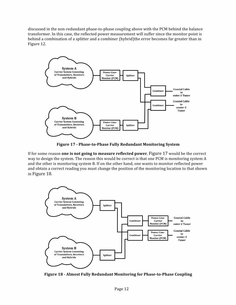
discussedinthenon-redundantphase-to-phasecouplingabovewiththePCMbehindthebalancetransformer.Inthiscase,thereflectedpowermeasurementwillsuffersincethemonitorpointisbehindacombinationofasplitterandacombiner(hybrid)theerrorbecomesfargreaterthaninFigure12.
Figure17-Phase-to-PhaseFullyRedundantMonitoringSystem
Ifforsomereasononeisnotgoingtomeasurereflectedpower,Figure17wouldbethecorrectwaytodesignthesystem.ThereasonthiswouldbecorrectisthatonePCMismonitoringsystemAandtheotherismonitoringsystemB.Ifontheotherhand,onewantstomonitorreflectedpowerandobtainacorrectreadingyoumustchangethepositionofthemonitoringlocationtothatshowninFigure18.
Figure18-AlmostFullyRedundantMonitoringforPhase-to-PhaseCoupling

Page13
Eventhoughwecan’tcallthisschemeinFigure18fullyredundant,itisasredundantasanysystemsincethelinetuner,couplingcapacitorandlinetrapthePCMsareconnectedisnomoreredundant.Afailureofanyoneofthosecomponentswillcompromisebothsystemssomewhat,butinmostcases,willnotcauseatotalfailureofeitherprotectionsystem.
TheinputtooutputcoaxconnectorinthePCMwillonlyhaveacurrenttransformerinserieswiththecenterconductorandavoltagetransformeracrossthecoaxcentertoshield.Afailureofeitheroftheseunitsaretheonlycomponentsinthemonitoringboxthatcancompromisethesystem.Thesetransformers,beingveryrobustandpassivecomponents,addverylittleprobablyoffailuretotheoverallprobablyoffailureofthelinetuner,couplingcapacitorandlinetrapcombination.So,theeffectofhavingthePCMinthelocationshowninFigure18intermsoffailureprobablyisverysmall.
Figure19-AlmostFullyRedundantMonitoringofMode1Coupling
Figure19aboveshowshowyouwouldarrangethemonitoringforamode1couplingscheme.ThesamecommentsasstatedabovefortheredundancyinFigure18alsoapplytothemode1coupling.RefertoReference3)foradetailedschemeshowingtransformerpolaritiesandconnectionsfortheschemeonFigure19
FIELDTESTINGOFCONCEPTUALDESIGNPCMapplicationTrialforPeriodicMaintenance&meetingNERCrequirementsatGeorgiaTransmissionCo.
Inthepast,periodictestingofpilotsystemshasbeenleftuptotheutilities.Thishasallowedthepilotsystemstobeinvariousstagesofworkingorder.Someutilitieswentoverboardandwereperformingtoomuchmaintenanceandotherswereneglectingtheirsystemsalltogether.Intoday’sregulatorycomplianceledworldthisisnolongeracceptable.Whilesomeminimumrequirementshavebeensetbytheregulations,muchoftheupkeephasstillbeenlefttotheutilities(seeReference[4]).Onlynow,whateveryourmaintenanceprogram,thegovernmentwillaudittheutilitiestoprovethatyourstatedmaintenanceprogramisbeingimplemented.
ThemaintenanceprocesswilltypicallyinvolvetestingoftherelayandPLCsystemtovalidatetheschemeisworkingcorrectly.Thisinvolvesensuringthecorrectsettingsareappliedandthe

Page14
inputs/outputsarefunctioning.Also,thismeanstakingtheschemesoutofservice,havingpeopleatbothendsoftheline,andtakingvariouschannelchecksandreadinglevels.Oncethisinformationhasbeengatheredandevaluated,thedecisionwillbemadewhethertodofurthercalibrationonyourtrapsandtuners.Maintenanceonyourtrapsrequirecrews,manliftsandsystemoutages.Inall,theutilitywillhaveengineers/techniciansandcrewspossiblytiedupfordaysatatimedependingonthesizeofthestationthatisduemaintenance.
WithaPowerLineCarrierMonitoringSystem,periodicmaintenanceofyourpilotschemeswillbecomestreamlinedandmoreefficient.
Let’stakeforexamplearoutinemaintenanceatahypotheticalSpringsubstation(seeonelinediagraminFigure20)equippedwithPCM’s.
2017RoutineatSpringSubstation
Figure20-OneLineDiagramofSpringSubstation
ThreeofthefourtransmissionlineshavePowerLineCarrier.
Spring–KingSt115kvLinehasaDCBscheme.
Spring–LukeWay115kvLinehasaDCUBscheme.
Spring–PeacockAve115kvLinehasaDCUBandTTRxScheme.
Spring–StDillard115kvLineisnon-pilotandprotectedbyZoneProtection.
AllpilotschemesconsistofthelatestPLCequipmentandmicroprocessorrelayswithremoteaccess.
EachpilotschemeisequippedwithaPCM.
Forthisdiscussion,themaintenancewillbebrokenintotwosections.
1. TheControlHouse-ThismaintenancewillconsistofthechecksontherelaysandPLCequipment.ThisinvolvesreadinglevelsandsettingmarginstoensurethePLCsareinworkingorder.Also,theinputs/outputsbetweentherelayandPLCsaretestedtobefunctioningcorrectly.
2. TheFieldEquipment-Thismaintenancewillconsistwiththegatheringofourchannelqualitychecks,specifically,ReflectedPower.Itwillalsoinvolveswappingsignalswiththeremoteterminal.Thistypeofinformationwillbeusedtodetermineifyourtunerortrapneedsattention.
TheControlHouse

Page15
Spring–KingSt115kvLineDCBScheme
DCBSchemesusingON-OFFPLCequemptarerequiredtohaveaperiodiccheckbacktest.ThistestisdonetoverifythePLCsetandthechannelareinbasicworkingorder.AsuccessfultestverifiesthePLCsetiscapableofkeying/receivingablocksignalwhichprovesthatthechannelbetweenthetwostationsisintact.
WithaPCM,onecansimplyremoteintotheboxandgatheryourfirstimportantpieceofinformation.AscanbeseenfromFigure21&Figure22,thePLCsethassuccessfullyshiftedfromOFFtoONstateforthetransmitterandthenaplaybackwasreceivedtoverifytheremoteend.
Figure21-SpectralAnalysisofTransmitterintheOFFState&ONState
Figure22-TheCorrespondingReceiveSignals
Spring–PeacockAve115kvLineDCUBSchemeDCUBschemeshaveanormally“On”GuardSignal.WiththePCMonecanseethesystemshiftingfromGuardtoTrip.RefertoFigure23,Figure24&Figure25.

Page16
Figure23-DCUBinGuard
Figure24-ShiftingtoDCUBTrip
Figure25-DCUBinTrip
Thisspectralanalysiswastakenfromasystemevent.TheDCUBTransmitterisputtingoutasolid10wattsata138.75kHzguardfrequency.
Asatestisinitiated,theradioisstartingtheshiftfromguardtotrip.Informationabouttheschemecanbegleamedfromthisevent.Forexample,inthepilotrelay,theactualrelayoutputisexercisedtothecarrierset,wheretheactualinputonthesetisenergizedcausingittokey.Essentially,theoutputsandinputsassociatedwiththecorrectfunctioningoftheschemeisverifiedbythespectralanalysis.
Heretheradiocompletesitsshiftfromguardtotripensuringusthatlocalendisfunctioningcorrectly.Dependingonthetypeofevent,theremaybeacompanionreceiveeventtogowiththistransmitevent.SimilartotheDCBscheme,anexternalcheckbacksystemappliedintheprogrammablelogicofyourpilotrelaycouldbeusedtoperiodicallycheckyourinputandoutputsbothlocallyandremotely.

Page17
Spring–LukeWay115kvLineDCUB/TTRxSchemeDCUBSchemeshaveanormallyonGuardSignalfortransmitandreceive.TheTransferTripReceivershavegoodGuardSignalsaswell.
Figure26-SpectralAnalysisSpring–LukeWay115kvLine
ThisspectralanalysisinFigure26capturesthecompletepicture.ItshowusthecompleteDCUBsystemandthetwoTransferTriprecivers.Theselevelscanbearchivedandusedforfutureschemeevaluations.
ControlHouseConclusion
Fromactualeventstocheckbacktests,theschemescanbedeterminedtohaveoperatedcorrectly.Theinputsandoutputsarevalidated.Thespectralanalysesshowthecarriersetisshiftingandreturningtonormal.Levelsarecapturedandarchived.Ifdataisgatheredandmaintained,someofyourrelayandradiomaintenancecanbeavoided.
TheChannel
Spring–KingSt115kvLineDCBSchemeSomeofthebasicreadingsandinitialvaluesweregatheredfromourControlHousereadings.Tocompleteourchecksofthepilotsysteminvolvestakingreflectedpowerreadings.Inthepast,wesubmittedworkrequeststodisabletheschemestoinsertourtestequipmenttotakeareading.NowwesimplyremoteintothePCMandtakeactualin-servicereadings.ADCBschemeisnormallyoffanditmustbekeyedtotakeareflected
1 2 34

Page18
powerreading.ThePCMcankeytheradiobypulsingitsoutput.Itthencancaptureareflectivepowerreading.
Figure27-In-servicereadings
Figure28-“AsLeft”ReadingsfromPastTesting
Asyoucanseefromtheabovereadings,thePCMcantakeanin-servicereadingthatcanbecomparedtoapast“AsLeft”reading.If,forexample,thereflectedpowerchangesbyonlyapercentortwo,itcanbeconcludedthatnothingsignificanthaschangedonyourline,inyourtuner,orwithyourlinetrap.IfyourinitialequipmentcalibrationsaredocumentedcorrectlyandthePCMisutilized,yourmaintenancefortheabovecanbeconsideredmuteandunnecessary.
PeriodicMaintenanceConclusion
TakingreadingsfromaPCMtakesamomentcomparedtothetypicalprocessofanengineerwithatestset.Onesuchmaintenanceintervalforasinglepilotschemecansaveyourcompanythousandsofdollars.
So,inconclusion,aPowerLineCarrierMaintenancedevice,ifproperlyinstalledandmaintained,cansignificantlyreducemaintenancecostsandschemedowntimes.Operationsonyoursystemwillbeeasilyidentifiableandinvestigated.Proper“AsLeft”datacanbeusedonanyequipmenttroubletohelpdocumentandtrendequipmentissues.PropertrendingwithyourspectralanalysiscouldhelputilitiesidentifyPLCissuesthatareathecauseforsystemincorrectoperations.TheusesofaPCMwillbeonlylimitedbyyourimagination.

Page19
PCMApplicationtrialatSouthernCaliforniaEdisonforTroubleShootingPLC
Overview:
SouthernCaliforniaEdison’s(SCE)TechnicalSupportandStrategy(TS&S)grouphasperformedacostbenefitanalysisofpermanentlyinstallingPCM’sasameansofreducingthecostsnormallyassociatedwiththemaintenance,operationandtroubleshootingofourPowerLineCarrier(PLC)schemes.SCEhasdeterminedthatthecostsrelatedwithmaintainingandtroubleshootingtheirPLCschemeshavebeenincreasing,largelyduetotheattritionrateofqualifiedtechnicianswhohavethenecessarybackgroundandexperiencerequiredtoworkonPLCsystems.They’vealsodeterminedthatwhentheirhigh-speedPLCprotectionsystemsareoutofservice,especiallyforextendedperiodsoftime,thereareincreasedrisksofclearingfaultswiththeback-upprotectionsystems.
SCErecentlyappliedaPCMtooneofitsPLCsystems,toexplorewaystobegintoreducethecostsofmaintainingitsPLCsystems,andtoprovidecontinuousmonitoringofthehealthofitsPLCsystems.TheywereintriguedbytheabilityofaPCMtoprovideapassive,non-evasive,methodofcapturingthecarriersignal’sspectraldata.Further,theywantedtoevaluateifapplyingaPCMwouldallowthemtoconsidertheirPLCsystemstofully-monitored,asameansofextendingthemaintenanceintervalsfortheirPLCsystems.
EvaluationofaPCM:
SCE’sTechnicalSupportandStrategygroupfirstevaluatedthesetupandoperationofaPCMintheirlaboratory,locatedinPomona,CA.WhiletheycoulddemonstratesomeofthebasicfunctionalityofaPCMintheirlaboratory,itsoonbecameapparentthattheirlaboratoryenvironmentdidnotcontainallthenecessary,realworldcomponentsofatruePLCsystem(linetuners,linetraps,transformerhybrids,skewedhybrids,etc.).Theysoondeterminedthatitwastimetotakethenextstep,andapplyaPCMononeoftheirPLCsystems.TheyalsofeltthatevenmoreidealwouldbetoapplyaPCMtooneoftheirPLCsystemsthathadahistoryofreliabilityissues.
Asluck,wouldhaveit,SCE’sSubstationTestgrouphadbeenhavingissuesintroubleshootingapowerlinecarrierdirecttransfertrip(PLC-DTT)protectionsystemappliedtoitsAntelope–Whirlwind500kVtransmissionline.RefertoFigure29forthePLCconnections.ThePLC-DTTsystemhadbeenproducingspuriousTripReceivedsignalsfromoneofitstwotransmitter-receiversets.ThesespuriousTripReceivedsignalswerebeingreceivedatjustoneofthelineterminals,specificallyatAntelope.Unfortunately,therehavebeencaseswhenthisPLC-DTTsystemhasincorrectlyoperated,trippingopentheAntelope–Whirlwind500kVlineatbothends,whenspuriousTripReceivedsignalswerereceivedatAntelopefrombothofthisPLC-DTT’receiver.
Interestingly,ineachcasewhenthespuriousTripReceivedsignalshadbeenreceivedatAntelope,therewerenoindicationsofthecorrespondingTripSentsignalbeingsentfromtheoppositeWhirlwindlineterminal.ThisspuriousTripReceivedsignalissuehadbeengoingonforwellovertwo(2)years,andduringthattime,manydifferentTestcrewshadspenttimeonsite,troubleshootingthisissue.ThisspuriousTripReceivedsignalatAntelopehasresultedinthisPLC-DTTbeingremovedfromserviceforovertwoyears,now.Fortunately,inaccordancewithSCE’sstandards,there’saseconddirecttransfertripsystemappliedtothissame500kVtransmissionline,whichutilizesdigital

Page20
Figure29-SCE’sAntelope-Whirlwind500kVPLC-DTTSystemConnections
microwavecommunications,commonlyreferredtoasMW-DTTatSCE.Thus,eventhoughthis500kVline’sPLC-DTTsystemhasbeenout-of-serviceformorethantwoyears,thissameline’sMW-DTTsystemhasremainedin-service,providingthedirecttransfertripcapabilitiesforthisline.
Asalast-ditcheffort,SCEsentthetransmitter/receiverunitsfromthisAntelope–Whirlwind500kV’sPLC-DTTsystembacktothevendor,withthehopesthattheycouldfindsometypeofissuewiththeirtransmitter/receiverunits.Unfortunately,theyfoundnoissueswiththesetransmitter/receiverunits,andtheyreturnedtheseunitsbacktoSCE.ThisAntelope-Whirlwind500kVPLC-DTTsystemhasbeenout-of-serviceforovertwoyears
Consideringtheabove,SCE’sTS&SgroupfeltthatthisAntelope–Whirlwind500kVPLC-DTTsystemwouldbeanidealcandidatetoevaluateaPCM.TheunreliabilityofthisPLC-DTTsystemhascostSCEmanyman-hoursoftroubleshooting,operationsswitchingcost,andthelossofoneoftheprotectionschemesonanin-service500kVtransmissionline.ItwasfeltthatapplyingaPCMtothisPLC-DTTsystemwouldprovidebenefitsbecauseofthereal-timedatacapture,andmightevenhelpSCE’sTestcrewstoresolvetheunreliabilityissueswiththisPLC-DTTsystem.
PilotApplicationofaPCM:
Inearly2016,SCE’sTS&SgroupbegantheirpilotevaluationofaPCM,astheyworkedtogetherwithfieldTestcrewstoinstallaPCMateachendoftheAntelope–Whirlwind500kVline’sPLC-DTTsystem.Figure29showsthatatbothAntelopeandWhirlwind,aPCMwasinstalledinserieswiththetri-axialcableconnectedbetweenthehybridcombinerunitandthelinetuner.

Page21
LookingbackattheeventrecordsfromthisPLC-DTTsystem,itsoonbecameapparentthattherewasnoparticulartimeofdaythattheTripReceivedsignalswerebeingreceivedatAntelope.InordertoprovideanaccuratetimestampofthedatatoberecordedbythesePCM’s,aGPSreceiver’sIRIG-BtimesynchronizationwasconnectedtoeachPCM.
ItwashopedthatthePCMswouldprovidetheabilitytoobservesomeofcharacteristicsofthepowerlinecarriersignal,suchastransmittedpower,receivedpower,andreflectedpower.OncethesePCMswereinstalledandpoweredup,itwasnotedthatthesetheythecapabilitytomonitorthesethree(3)characteristicsofapowerlinecarriersignal,alongwithmanyothercharacteristics(refertoFigure27).
Capturingthesepowerlinecharacteristicsovertimeallowsdetailedanalysistobeperformed,whichmayhelptodeterminethecauseoferroneoustripswhichoccurduetospuriousnoise,intermittentlossofsignal,etc.Further,theabilitytostorethesepowerlinecharacteristics,astheyoccurovera24-hourtimeperiodthroughouttheyear,canbeveryhelpfulintheefforttomaintainthereliabilityofthesepowerlinecarriersystems.
DataCollectionandAnalysis:
SCE’sTS&SgrouphasbeentakingadvantageofthestoragecapabilitiesofthesePCMs,inorder,tocaptureeventrecordsstoredwithinthesetwo(2)PCM’s.
"ID","Date","Time","FFT","Channel","Description""20","04/15/2016","16:46:27:267","0","0","RFVoltageinRange""19","04/15/2016","16:46:26:519","0","0","RFVoltageOverload""18","04/15/2016","16:44:58:887","0","0","ConfigurationAccess""17","04/15/2016","16:44:58:615","0","0","AccountLoginadmin""16","04/15/2016","16:00:31:457","0","5","85-3FSKDTTRXLowFreq:GUARD""15","04/15/2016","16:00:30:783","1","5","85-3FSKDTTRXHiFreq:TRIP""14","04/15/2016","15:51:33:048","1","3","85-2FSKDTTRXHiFreq:GUARD""13","04/15/2016","15:51:32:349","0","3","85-2FSKDTTRXLowFreq:TRIP""12","04/15/2016","15:32:19:109","0","1","85-2FSKDTTTXReflectedOK""11","04/15/2016","15:32:18:900","0","5","85-3FSKDTTRXLowFreq:GUARD""10","04/15/2016","15:32:18:900","1","3","85-2FSKDTTRXHiFreq:GUARD""9","04/15/2016","15:27:46:509","1","1","85-2FSKDTTTXReflectedO/R""8","04/15/2016","15:27:46:309","1","5","85-3FSKDTTRXSignalO/R:Low""7","04/15/2016","15:27:46:309","1","3","85-2FSKDTTRXSignalO/R:Low""6","04/15/2016","13:09:46:452","0","0","TimedAccountLogoff:admin""5","04/15/2016","12:41:59:102","0","0","IRIG-BSynch""4","04/15/2016","12:40:31:709","0","0","ConfigurationChange""3","04/15/2016","12:40:30:239","1","3","85-2FSKDTTRXHiFreq:GUARD""2","04/15/2016","12:40:30:237","1","2","85-3FSKDTTTXLowFreq:GUARD""1","04/15/2016","12:38:56:021","0","0","IRIG-BUnsynch""0","04/15/2016","12:36:59:567","0","0","AuditLogCleared"
Figure30-ExampleEventRecordsofafromSCE’sAntelopeSubstation
TheeventrecordstypicallycapturedbyaPCM(Figure30)haveallowedtheend-usertoobservetime-taggedoperationalcharacteristicsoftheirrespectivePLCsystem,inthiscase,forSCE’sAntelope–Whirlwind500kVline’sPLC-DTTsystem.FortheAntelope–Whirlwind500kVline’sPLC-DTTsystembeingmonitoredbytwo(2)PCM’s,theresultshavebeenverytypicalforthirty-sixhundred(3,600)individualeventrecordstoberecordedoveraforty(40)dayperiod.

Page22
InadditiontotheabilityofaPCMtocaptureandstorethesetypeofeventrecords,aPCMalsohasthecapabilitytocaptureandstoreFastFourierTransform(FFT)displaysofthepower-line-carriersignalbeingmonitored.Figure23,Figure24&Figure25showsomeexamplesofthesetypesofFFTdisplays,andthissetofthree(3)displaysshowstheshiftofoneofthetransmitterswithinSCE’sPLT-DTTsystemfromguardtoitsrespectivetripfrequency.
PreliminaryanalysisofboththeeventandFFTdatacapturedbythetwo(2)PCM’sinstalledonSCE’sAntelope–Whirlwind500kVline’sPLC-TTsystemhasshownaverydistinctpossibilityofflashoversoccurringacrossthedraincoil’ssparkgapsappliedonthisPLC-DTT’ssystem.ThedatacapturedbythesePCM’sshowanintermittentlossofguardsignaloccurringattheAntelopelineterminal.TheadditionoftheGPSreceiver’sIRIG-Bsignaltothesetwo(2)PCM’shasproventobeextremelyvaluable,sincetheseeventshavebeenshowntobeveryfrequentandunrelatedtoweather.FurtherdetailedanalysisoftheeventrecordsandFFTdisplaysfromthesePCM’shaveshownthatthelikelysourceoftheseeventsisaresultofpowerlinenoise,whichisaresultoftheswitchingofpower-factorcorrectioncapacitorbanksappliedtothesolarandwindpowergenerationinstallations,whichareinstalledveryclosetotheright-of-wayofSCE’sAntelope–Whirlwind500kVtransmissionline.
SCEispresentlyworkingtogetherwiththevendorofthetransmitter/receiverequipmentappliedtoitsAntelope–Whirlwind500kVline’sPLC-DTTsystem,toexplorewaystomodifysomeoftheoperatingcharacteristicsoftheirtransmitter/receiverunits,tomakethisPLC-DTTsystemmoreresilienttotheabovesourcesofpowerlinenoise.ThedecisiontoinstallaPCMatbothendsoftheirAntelope–Whirlwind500kVline’sPLC-DTTsystemhasprovidedSCE’sTS&SgroupwiththetechnicaldatatheyneededtodeterminethecausebehindthereliabilityissuestheyhadbeenhavingwiththisPLC-DTTsystem.
CONCLUSIONSAPCMtypedeviceprovidestheuseranewtooltomonitor,maintainandtroubleshootapower-line-carriersystemusedforsystemprotection.ThecombinationofextendingmaintenancecyclesandmonitoringthesystemforunexpectedchangestypicallyrecoversthecostofthedeviceinarelativelyshorttimeandhelpstheuserbettercomplywithNERCstandardPRC-005-002[4].Theeventlogs/alarms,trendingandeventdrivenspectralanalysisprovidelongtermmonitoringofthesystemforyearsandameansforavoidingand/orevaluatingmisoperationsthatmayoccurinthefuture.Thisindependentmonitoringdeviceprovidestheuseraddedconfidencethatvaluableinformationwillbeavailable(withouttheneedforlineoutages)whenneededtoprovidedirectiontoapossiblesolutionandcauseoftheproblem.
REFERENCES1) IEEEStd643-2004,“IEEEGuideforPower-LineCarrierApplications”,2005
2) MiriamSanders&RogerRay,“Power Line Carrier Channel & Application Considerations For Transmission Line Relaying”, Ametek Power Publication #C045-P0597, 1997
3) IEEEPSRCWorkingGroupReport,“RedundancyinCouplingPowerLineCarrierChannelstothePowerLine”,WG15,2011
4) NERCStandard,PRC-00502,“ProtectionSystemMaintenance”

Page23
AUTHORBIOGRAPHY’SRobertBaldwin
RobertreceivedaB.S.E.E.fromCaliforniaStateUniversity,LongBeachin1982,andanM.S.E.E.fromCaliforniaStateUniversity,LosAngelesin2007.He’sspentover32yearsatSouthernCaliforniaEdison(SCE),holdingpositionsofSubstationElectrician,TestTechnician,ShopEngineer,ProtectionEngineer,OperationsTrainer,TestSchoolSupervisor,andmostrecently.SeniorTechnicalSpecialistintheirRelay/Testgroup.DuringhistenureatSCE,hisprimaryfocushasbeenwiththeapplication,settingandtestingofprotectiverelays,powerlinecarriersystems,anddigitalfaultrecorders.RobertisapastChairoftheGeorgiaTechTransientRecorderUser’sCouncil.
JeffreyBrown
Graduated1997withaBachelorofScienceinEngineeringfromGeorgiaTechUniversity.Aftergraduation,heworkedforGeorgiaPowerfor25yearsandfinishedasTeamLeaderforPowerLineCarriercoveringtheStateofGeorgia.HepresentlyworksforGeorgiaTransmissionCorporationasPrincipalEngineerTransmissionandPowerLineCarrierSupport.HeistheauthorofPowerLineCarriers:Simplified.
RayFella
RayreceivedhisBachelorofScienceinElectricalEngineeringin1987fromRutgersUniversityinNewBrunswick,NJ.Hehasspenthis30-yearcareersupportingtheElectricUtilitySystemProtectionCommunicationsindustry.In2001,hejoinedPowerCommSolutions,LLCasBusinessDevelopmentDirectorwherehereceivedhisfirstpatent.PriortoPowerCommSolutions,heworkedforSignalcraftersandstartedhiscareerwithINIVEN.Heisa28yearmemberofIEEE,amemberofthePowerandEngineeringSociety,aswellasnumberofworkinggroups.
AlanJayson
Alanhasspentthelast31yearsdesigningvariousaudiotoneandpowerlinecarriercommunicationandinstrumentationproductsfortheElectricUtilitysystemprotectionindustry.Hestartedhiscareerin1986withINIVEN,wherehelpeddesignprotectioncommunicationsystemsthatarestillinusetoday.In2012hejoinedPowerCommSolutionsasleaddesignengineerandpriortothatworkedforSignalcraftersfor14years.Heisalsoapatentholder.
RogerRay
RogerreceivedaBSinElectricalEngineeringatthePennsylvaniaStateUniversityin1964andanMSdegreeattheNewJerseyInstituteofTechnologyin1976.
HeisamemberoftheIEEEandamemberofthePower&EnergySocietyandtheCommunicationsTechnologySociety.HeispastChairmanof(whatwasthen)theIEEEPowerSystemCommunicationsCommitteeandispresentlyChairmanofthePowerLineCarrierSubcommitteeofthePSCC.HeisalsoamemberofthePowerSystemRelaying&ControlCommittee.Intheyear2000,hewasalsoelectedasaFellowintheIEEE.
HeisanauthoroftwochaptersintheWestinghouseAppliedProtectiveRelayingBook.Heauthoredseveralpapersinhismajorfieldsofpilotrelaysystemsandpowersystemcommunications.ThesepapershavebeenpresentedatmajorrelayconferencesaroundthecountryaswellasconferencesoutsidetheUS.He,alongwithco-authorShanSun,receivedtheIEEEPowerEngineeringSocietyPrizePaperAwardfor1983andheholdsfivepatentsintheUSonsubjectscoveringphasecomparisonrelaying,powerlinecarrier,andfiberoptics.

Page24
NeilStone
NeilreceivedhisBSEE-ITTTechnicalInstitute,SanDiego1998andPMPCertification–UniversityOfIrvineCa,2010.HeisalsoanIEEEMember.Neil’sworkexperienceincludesthefollowing:SonyCorp,applicationsengineer,RFCDMAdeploymentwithQualcomm(3years),PentadynePower,applicationsengineer,commercialflywheelUPSsystems(4years),ABB-PowerOne,fieldengineer,commissioncommercialUPSsystems(4years),SouthernCaliforniaEdison–NuclearTest(3years),NuclearStartupEngineer(2years),NuclearMaintenanceGeneralForeman(3years),SouthernCaliforniaEdison–TechnicalSpecialist/ScientistforTransmission&Distribution,StartupEngineer(3years)andiscurrentlyworkingwithSouthernCaliforniaEdisonasTechnicalManagerforTransmission&Distribution,RelayTestandTechnicalSupport(2years).