Embed Size (px)
Citation preview
5 Parker Hannifin CorporationCompumotor Divisioncompumotor.com
The ACR Family of ControlsSince the acquisition of Acroloop Motion Control Systems in2002, the ACR family has been the highest performancemotion controls in the Parker offering. Each of the five versionsof the product is based on a 32-bit floating-point DSP produc-ing unparalleled performance in the area of advanced multi-axistrajectory generation. Because the products are built upon ascalable platform, the same software set works on each of thecontrollers, providing easy upgrades and transfer of establishedapplication code between machines and applications. Thehardware is also extremely flexible, allowing the design engineerto easily create the perfect controller configuration for hismachine. The power of the ACR hardware is matched by anequally impressive array of software features allowing thedesign engineer the ability to solve any motion application.
Features:
• Backlash and ballscrew compensation• Hardware and capture registers
• S-curve profiling• String handling• Time-based moves• Synchronized master moves• Segmented cams• High-speed triggered cams• Dual-feedback control (velocity and position)• Analog or digital feedback• Stepper or servo outputs• Onboard diagnostics• Onboard oscilloscope• Software limits• Torque limits• Spline moves• NURBS• 3-D arcs• Sinusoidal commutation• Automatic tangential tool orientation
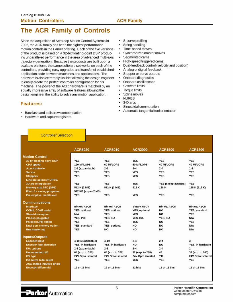
Controller Selection
ACR8020 ACR8010 ACR2000 ACR1500 ACR1200
Motion Control32-bit floating-point DSP YES YES YES YES YESCPU speed 120 MFLOPS 60 MFLOPS 50 MFLOPS 40 MFLOPS 40 MFLOPSAxes/controller 2-8 (expandable) 2-8 2-4 2-4 1-2Servos YES YES YES YES YESSteppers YES YES YES YES YESLine/arc/splines/NURBS,3D arc interpolation YES YES YES YES (except NURBS) YESMemory size STD (OPT) 512 K (2 MB) 512 K (2 MB) 512 K 128 K 128 K (512 K)Flash for saving programs 512 KB (expan 2 MB)Pre-emptive multitasker YES YES YES YES YES
CommunicationsInterface Binary, ASCII Binary, ASCII Binary, ASCII Binary, ASCII Binary, ASCIICOM1, COM2 serial YES, optional YES, optional YES, optional NO YES, standardStandalone option N/A YES YES NO YESPC-bus pluggable YES, PCI YES, ISA YES, ISA YES, ISA N/AParallel (LPT) option YES YES YES NO YESDual-port memory option YES, standard YES, optional NO NO N/ABus mastering YES NO NO NO N/A
Inputs/OutputsEncoder input 4-10 (expandable) 4-10 2-4 2-4 3Encoder fault detection YES, in hardware YES, in hardware NO NO YES, in hardwareD/A options 2-8 (expandable) 2-8 2-4 2-4 2Uncommitted I/O 64 (exp. to 320) 64 (exp. to 320) 32 (exp. to 288) 48 32 (exp. to 160)I/O type 24V Opto isolated 24V Opto isolated 24V Opto isolated TTL 24V Opto isolatedI/O active hi/lo select YES YES YES YES YESAUX analog inputs 8 singleEnded/4 differential 12 or 16 bits 12 or 16 bits 12 bits 12 or 16 bits 12 or 16 bits
Motion ControllersCatalog 8180/USA
ACR Family zc01
6 Parker Hannifin CorporationCompumotor Divisioncompumotor.com
Real-Time Motion ControlWith Floating-Point DSP
Ensuring the highest possible performance, ACR controllersuse high-speed Digital Signal Processors (DSPs) from TexasInstruments for real-time calculations and motion control. TIDSPs feature:
• 40-120 MFLOPS• Floating-point calculations• Superior speed and accuracy (over fixed-point).
The ACR’s processor-based controllers can quickly processfloating-point calculations on-board, typically in the 100-500usec range (products using software calculations are typically inthe 5000-8000 usec range). This frees the controller to servicea pre-emptive multi-tasker, with up to 24 programs at once,and service up to four communication channels concurrently.Thus, means you can communicate with an ACR controller fortroubleshooting and still have the HMI on a production machinefully online and active!
Analog/Stepper Flexibility
The Acroloop Motion Controllers can be set up to accom-modate stepper or servo analog outputs. The controllers canbe configured in combinations explained in the ordering matrixyou find within each ACR category. Analog inputs at 12 or 16-bit resolutions are available as options. These may be fieldconfigured as single-ended or differential inputs.
Pre-Emptive Multi-Tasker
ACR controllers are true pre-emptive multi-taskers capable ofperforming multiple tasks simultaneously and toggling tasksbased on the condition of a bit. A pre-emptive multi-tasker isthe best choice when you have a program that need not alwaysrun, but needs to be available to run. For example, if you needto dress a wheel on a grinder based on an input or parametricequation, it would be a waste of time to have this programbeing serviced constantly. Without a pre-emptive multi-tasker,it would be necessary to allocate time for this little-usedprogram. In a pre-emptive situation, the program would bedormant until called for, and only then would it require time tobe serviced. Because of the ACR controllers’ standard on-board operatingsystem, time-critical events can be off loaded to the controller.This is important, since the loading and therefore timing issuesof the host PC CPU are variable and the programmer cannotbe sure of real-time execution.
Pre-Emptive Multi-Tasker Features
• Perform up to 8 motion programs (25 usec/axis servoupdate rate).
• Perform up to an additional 8 programs (non-motionprograms).
• Perform up to 8 PLC programs (1-5 msec scan time).• Command up to 4 communication ports simultaneously• Perform motion programs, PLC programs, and multi-
threaded communications simultaneously.• Troubleshoot from one port while the standard communi-
cation port is active with the HMI.• Communicate over the PC-Bus, and two serial ports
simultaneously.• Real-time application programming can be off-loaded to the
ACR controller to ensure real-time execution.
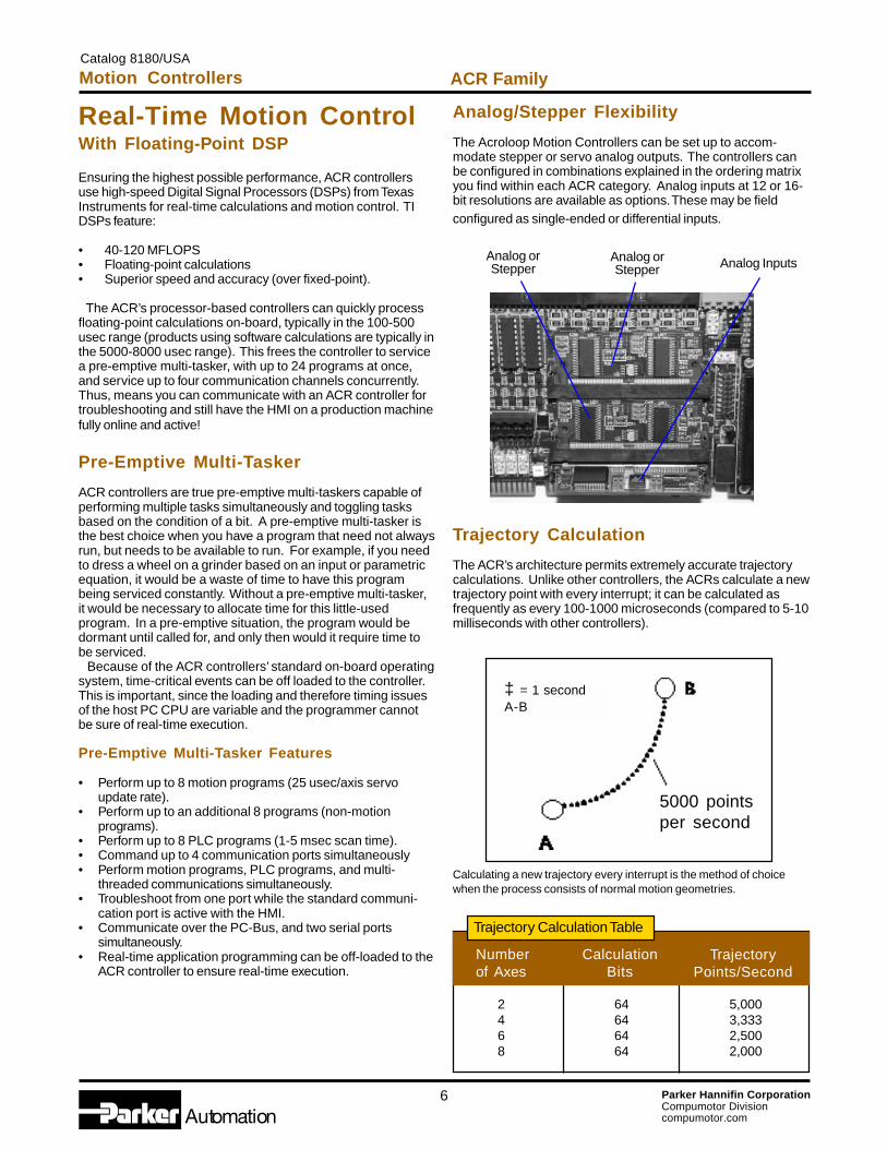
Trajectory Calculation
The ACR’s architecture permits extremely accurate trajectorycalculations. Unlike other controllers, the ACRs calculate a newtrajectory point with every interrupt; it can be calculated asfrequently as every 100-1000 microseconds (compared to 5-10milliseconds with other controllers).
Numberof Axes
CalculationBits
TrajectoryPoints/Second
Trajectory Calculation Table
2 64 5,0004 64 3,3336 64 2,5008 64 2,000
Analog orStepper
Analog orStepper Analog Inputs
Calculating a new trajectory every interrupt is the method of choicewhen the process consists of normal motion geometries.
5000 pointsper second
‡ = 1 secondA-B
Catalog 8180/USA
Motion Controllers ACR Family
7 Parker Hannifin CorporationCompumotor Divisioncompumotor.com
Cubic Splines
ACR controllers provide cubic spline interpolation. Highlightsinclude :
• Smoothness of continuous first and second derivatives of position• Ability to handle uniform and non-uniform data points• Ability to define initial and final velocity to blend with other motion profiles• Goes through data points precisely• Spline interpolation can be time-based or velocity-based.
NURBS
Figure 1. Example of how points can be randomly spaced in time,greatly reducing program length.
ACR controllers provide Non-Uniform Rational Basis Splines, orNURBS. NURBS are industry standard tools for the represen-tation and design of geometry. These give ACR controllers amathematical method for defining an entire curve of up to eightaxes. Highlights include:
• Free-form curves can be accurately defined• Suitable for high-speed machining up to eight axes• Gives better surface finish• Shorter program and fewer data points• No break between points at high speed• No need for high-speed data transfer from the host• No error due to approximating NURB curve by smaller linear line segments.
Figure 2. Example shows few control points needed to draw randomshape and accompanying program.
Splines and NURBSAdditional Features• Dynamic Feed Rate override• Feed Hold and Cycle Start facility, like normal moves• Any source with source scaling, like normal moves• Blending with other motion profiles; allows normal line/arc
move at the beginning or end of spline/NURB segment• Unique mix of modes only offered by Compumotor.
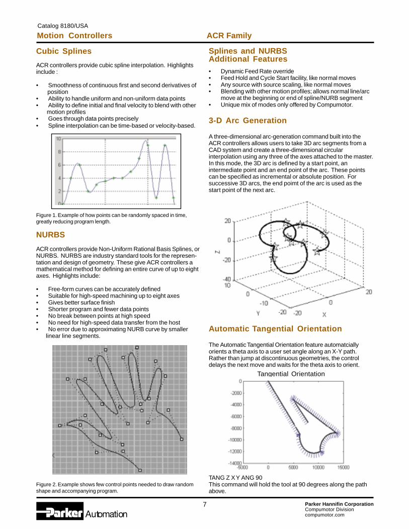
3-D Arc Generation
A three-dimensional arc-generation command built into theACR controllers allows users to take 3D arc segments from aCAD system and create a three-dimensional circularinterpolation using any three of the axes attached to the master.In this mode, the 3D arc is defined by a start point, anintermediate point and an end point of the arc. These pointscan be specified as incremental or absolute position. Forsuccessive 3D arcs, the end poimt of the arc is used as thestart point of the next arc.
Automatic Tangential Orientation
The Automatic Tangential Orientation feature automatciallyorients a theta axis to a user set angle along an X-Y path.Rather than jump at discontinuous geometries, the controldelays the next move and waits for the theta axis to orient.
Tangential Orientation
TANG Z X Y ANG 90This command will hold the tool at 90 degrees along the pathabove.
Motion ControllersCatalog 8180/USA
ACR Family

8 Parker Hannifin CorporationCompumotor Divisioncompumotor.com
CAM – Electronic Cam
The CAM command is used to create motion that emulates amechanical cam. The ability to segment the CAM gives theprogrammer flexibility. The CAM profiler will automaticallylinearly interpolate between any two points regardless of thedensity of the points.
TMOV – Time-Based Move
The TMOV command allows moves to be completed in aspecific amount of time. Prior to TMOV, the programmer wouldneed to program with a calculator to determine the speed,acceleration and deceleration needed to arrive at a destinationin a specific amount of time.
TRG CAM – Triggered Cam
The TRG command solves the problem of following error dueto the time delay between a triggered input and the actual startof physical motion. For example, if a web line is moving at 60feet per second and there is a 2-microsecond hysteresis beforemotion takes place, the result will be an error:
The TRG CAM command negates this and thereforeincreases repeatability and accuracy to within on microsecond.Barring mechanical limitations, the electronic accuracy is nowimproved by a factor of 2000 to 0.007”.
Using SYNC moves rather than coordinated moves givesusers the flexibility of using different motion profiles for differentmasters while still keeping them in sync.
60ft/sec x 12in/ft = 720in/sec x .002sec = 1.44 inches of error
The figure above shows a velocity vs. time graph for five axesattached to different masters that move with independentaccelerations and decelerations, yet are synchronized amongstthemselves. They all complete their moves within theprescribed time interval of tmsec specified by the user. Thismechanism can be useful in coil-winding applications when thewire feed moves continuously yet other axes must come andgo at their own pace while remaining synchronized to the wirefeed.
Once Velocity, Accel and Decel are set on the defaultsettings, TMOV will calculate Velocity, Accel and Decel basedon length and time of move.
Backlash and Ballscrew Compensation
Backlash and Ballscrew Compensation allow the user toelectrically compensate for the inherent inaccuracies of theirmechanical systems. The Backlash Compensation simplytakes into account the mechanical backlash when changingdirection on the mechanical system. Once the backlash valueis entered into the system, the ACR controller automaticallycompensates for lost travel due to backlash when changingdirection, thus ensuring accurate positioning. The ballscrewcompensation feature allows the user to map the inaccuracy ofthe mechanical actuator along the entire travel length requiredby the application. Once this inaccuracy is mapped, the ACRcontroller automatically compensates by cross-referencing thecorrection map and adjusting the commanded position of theaxis to ensure the actual desired position is reached on the loaditself. This capability allows the user to eliminate the costlylinear encoder often used to compensate for mechanicalvariations along the travel of the actuator.
SYNC – Master Synchronizing
It is sometimes necessary to run several coordinated groups ofaxes’ masters in synchronization with another master. Insewing, for example, if an X-Y table is under a needle, the tablecan only move when the needle is up and out of the fabric. Inthis example, the SYNC command can be used to coordinatethe movement of the needle to the movement of the table.
Catalog 8180/USA
Motion Controllers ACR Family

9 Parker Hannifin CorporationCompumotor Divisioncompumotor.com
ACR FamilyMotion ControllersCatalog 8180/USA
Dual Feedback Control
The Dual Feedback capability of the ACR products allows theuser to close two loops of feedback around a single mechani-cal axis. One encoder is found on the servo motor and anotheron the load itself. This allows the ACR controller to automati-cally compensate for the inherent mechanical compliancewithin the traditional screw driven actuator. The position loop isclosed with the load encoder while the velocity loop is closedwith the motor encoder. This ensures the most accuratepositioning possible while maintaining stiffness required foraggressive acceleration and velocity moves.
Floating-Point Mathematics Precision
Provided with 64-bit precision floating-point math functions,ACR controllers give you:
• Six “decimal” digit numbers as standard and 16 “decimal”digit floating-point numbers to provide greater accuracy
• Global and local variable operation• Simultaneous performance of intermediate calculations for
trajectories, parametric evaluations, PLC operations, high-speed position captures and many other tasks.
Compare the 32-bit and 64-bit precision floating-point variablesto other motion controllers; you won’t get rounding errors withthe ACR controllers. For example, a simple electronic gearingratio can be set to a floating-point number unlike othercontrollers with limited gear ratio ranges. If a PC host is used, itonly requires updating the graphical display and feeding newoperator information to the motion controller; the ACRcontrollers take care of everything else.
LOCK – Gantry Lock Control
The LOCK command redirects one axis to follow the primarysetpoint of a second axis. This command is essential forcontrolling a gantry system where two mechanical systemsneed to be coupled. Once the two axis are locked, a specialcontrol loop will minimize the error between the two axisassuring perfect coordination.
LOOK – Dynamic Multi-block LookAhead
In many machining and assembly operations, it is essential thatovershoot be minimized in order to maintain quality and finish inthe part being produced. The LOOK ahead commanddynamically analyzes upcoming move parameters to assurethat the system can perform the desired move. If the movesare too demanding for the system to execute, the move profilewill automatically be limited to the maximize speed that cancomplete the desired move.
Simultaneous CAM, Gear and Jog
The unique setpoint summation technique of the ACR controlsallows up to 3 different move profiles to be superimposed ontoa commanded move. This unique technique allows themachine builder to accommodate for changes in environmentalconditions such as temperature and will allow a cam profile tobe advanced or retarded very simply. ACR controllers alloweasy integration into vision systems by allowing offsets mea-sured by the camera to be superimposed “on the fly” withoutthe need of changing a distance parameter and making anadditional move.
CurrentPosition
Primary SetpointGear Offset
Jog Offset
Cam Offset
10 Parker Hannifin CorporationCompumotor Divisioncompumotor.com
The ACR controllers are unique since they can communicateboth ASCII and binary simultaneously. Benefits of this “twoaccess doors approach” include:
• Unrestricted integration of front-end software designs• Simple ASCII codes can be transmitted to the board over
any of the on-board communications ports (COM1, COM2,LPT and the PC-bus)
• Communications can be increased dramatically to allowincreased data throughput to and from the controller.
Simultaneous Port Access
ACR firmware is engineered for maximum flexibility with anopen design allows designer complete access to virtuallyevery possible motion control parameter and flag. There are upto eight masters and up to eight axes on an ACR controller. Amaster controls a group of axes; therefore, each mastercontrols a unique group of variable that can be monitored orchanged on-the-fly.
Hardware Parameter Access
Tables A and B illustrate the Master and Axis parameters. Forexample, the vector velocity for MASTERprofiler 0 is stored inhardware parameter number P8193. Variable P8193 is a 32-bitfloating-point variable. If the programmer wanted to display thecurrent position of AXIS0 on the operator display, a requestwould be made to the ACR controller to retrieve the 32-bit-longinteger stored in hardware register P12288. There are approxi-mately 15,000 parameters pre-programmed into the ACRcontrollers.
Table A: Master Parameters Examples
Position Parameters Type MASTER0
Vector Position FP32 P8192
Vector Velocity FP32 P8193
Vector Acceleration FP32 P8194
Vector Jerk FP32 P8195
Vector Length FP32 P8196
Target Velocity FP32 P8196
Target Acceleration FP32 P8197
Table B: Axis Parameters Examples
Position Parameters Type AXIS0
Current Position LONG P12288
Target Position LONG P12289
Actual Position LONG P12290
Following Error LONG P12291
Hardware Capture LONG P12292
Software Capture LONG P12293
Primary Setpoint LONG P12294
Secondary Setpoint LONG P12295
PLS – Programmable Limit Switch
The PLS command allows sequencing an output parameter(usually physical I/O bits) based on the changing values of aninput parameter (usually an encoder). The simpliest PLS isused in most drum sequencers found in washing machines tocontrol wash cycles.
The ACR PLS allows user to:
• Select from a variety of output parameters• Advance and retard the source parameter and mask and
scale the output parameter• Control the number of I/O bits the PLS operates on.
HSINT – High-Speed UninterruptibleMove
The HSINT command gives the programmer a way to initiate anincremental move based on an input. On webs it is common toinitiate motion on the leading edge of a marker. With the command, one needs to define a target position,then a window. Then point to an input and the controller willinitiate the incremental move once it reaches the correct state.All this is accomplished at high speed due to the 1-microsecond latching of any input or parameter
Motion ControllersCatalog 8180/USA
ACR Family

11 Parker Hannifin CorporationCompumotor Divisioncompumotor.com
The ACR8020 is Compumotor’s premier controller for PCIbus operation. It has the ability to run eight servo loops (16with expansion board), DAC or Stepper outputs and 10encoders (20 with expansion board) at 20 MHz counting rate. Itcan also be equipped with up to 8 analog (12- or 16-bitresolution) inputs. Multi-axis coordinated motion can beperformed in multiple groups of axes. Because of theACR8020’s modular design, a combination of both servo andstepper axes can be applied on the same controller. All ofCompumotor’s Acroloop products utilize the same systemsoftware and programming language; this assures userscomplete flexibility in upgrading their hardware while maintain-ing their investment in program development. The ACR8020’s processing speed is unmatched in theindustry at 120 Mega Floating-point Operations Per Second(MFLOPS)!
PCI/PC BusOperation
ACR8020 Exclusives
• 120 MFLOPS, 32-bit floating-point DSP• 8 axes of servos or steppers (expandable to 16)• 10 encoder inputs at 20 MHz (expandable to 20)• User and system memory 512 KB (expandable to 2 MB) each• Encoder loss and fault protection• 64 optically isolated 24VDC I/O expandable to 320 I/O• Dual-port memory standard• Master PCI DMA interface• Full-size PCI card• Optional communications interface (includes 2 serial ports– RS232/RS422/RS485–and 1 parallel port)
ACR8020 (1- to 8-Axes) Ordering
Catalog 8180/USA
Motion Controllers ACR8020
12 Parker Hannifin CorporationCompumotor Divisioncompumotor.com
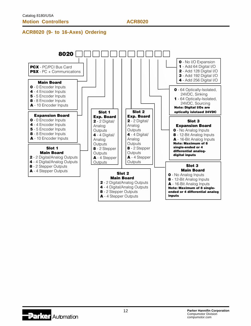
ACR8020 (9- to 16-Axes) Ordering
Motion ControllersCatalog 8180/USA
ACR8020

13 Parker Hannifin CorporationCompumotor Divisioncompumotor.com
ACR8020 Specifications
ValueHardware
Axes/controller 2-8 axes (Expandable to 16)PC-Bus interface PCIStandalone option NAProcessor 32- /64-bit floating-point DSP @ 120 MFLOPS / 60 MHzTrajectory calculation 64-bit precisionUser memory 512 KB (expandable to 2 MB); 2 MB (standard for 9- to 16-axes cards)System memory 512 KB (expandable to 2 MB); 2 MB (standard for 9- to 16-axes cards)Firmware Flash-basedFlash memory 512 KB (expandable to 2 MB)Size Full-size PCIOperating system Multi-tasking RTOS
PerformanceMulti-tasking 16 coordinated systems, motion/PLC programsTrajectory update Every 100-500 usecServo update 25 usec/axisLadder Logic PLC 100-500 usec scan timeInterpolation Linear, circular, sinusoidal, helical and elliptical, splines, NURBS, 3D arcsServo loop PID, velocity feedforward, acceleration feedforward notch, LoPass filteringPosition regulation Hardware, < 1usecCommunications Simultaneous PCI, serial and LPT ports
CommunicationsPC bus Bus mastering PCI with dual-port memoryOptional interface 2 serial ports (RS232 and/or RS422), 1 parallel port (8 bits)
InputsEncoder input 10 (expandable to 20) at 20 MHz post-quadratureAnalog input - Auxiliary Up to 8 (12- or 16-bit)
Command SignalAnalog outputs Up to 16 (16-bit precision)Stepper outputs Up to 16 @ 1 MHz
Digital I/O 64, 24 VDC optically-isolated (expandable to 320)Software Support
Standard language Visual Basic, Visual C++, C++Program tools AcroVIEW Motion/PLC ProgramDevelopment tools ActiveX controls/OCX controlsOperating system Windows® NT, 98, 2000, XPAdditional firmware highlights Triggered floating point electronic GEARING
Triggered segmented electronic CAMOn-the-fly position and velocity matchingLadder Logic PLCInterruptible movesEither analog or digital feedback for position or velocity loopsDual-encoder feedbackData teach and learn functionsParameter-based with over 15,000 addressable pre-defined hardware registersSinusoidal commutationNURBS and splines3D arcsAutomatic tangential tool operation
Catalog 8180/USA
Motion Controllers ACR8020
14 Parker Hannifin CorporationCompumotor Divisioncompumotor.com
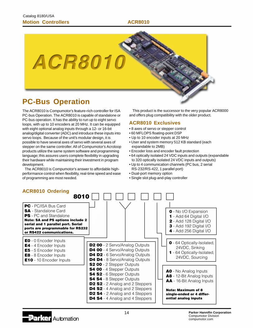
The ACR8010 is Compumotor’s feature-rich controller for ISAPC-bus Operation. The ACR8010 is capable of standalone orPC-bus operation. It has the ability to run up to eight servoloops, with up to 10 encoders at 20 MHz. It can be equippedwith eight optional analog inputs through a 12- or 16-bitanalog/digital converter (ADC) and introduce these inputs intoservo loops. Because of the unit’s modular design, it ispossible to have several axes of servo with several axes ofstepper on the same controller. All of Compumotor’s Acroloopproducts utilize the same system software and programminglanguage; this assures users complete flexibility in upgradingtheir hardware while maintaining their investment in programdevelopment. The ACR8010 is Compumotor’s answer to affordable high-performance control when flexibility, real-time speed and easeof programming are most needed.
PC-Bus Operation
ACR8010 Exclusives• 8 axes of servo or stepper control• 60 MFLOPS floating-point DSP• Up to 10 encoder inputs at 20 MHz• User and system memory 512 KB standard (each expandable to 2MB)• Encoder loss and encoder fault protection• 64 optically isolated 24 VDC inputs and outputs (expandable to 320 optically isolated 24 VDC inputs and outputs)• Up to 4 communication channels (PC bus, 2 serial RS-232/RS-422, 1 parallel port)• Dual-port memory option• Single slot plug-and-play controller
ACR8010 Ordering
This product is the successor to the very popular ACR8000and offers plug compatibility with the older product.
Motion ControllersCatalog 8180/USA
ACR8010
15 Parker Hannifin CorporationCompumotor Divisioncompumotor.com
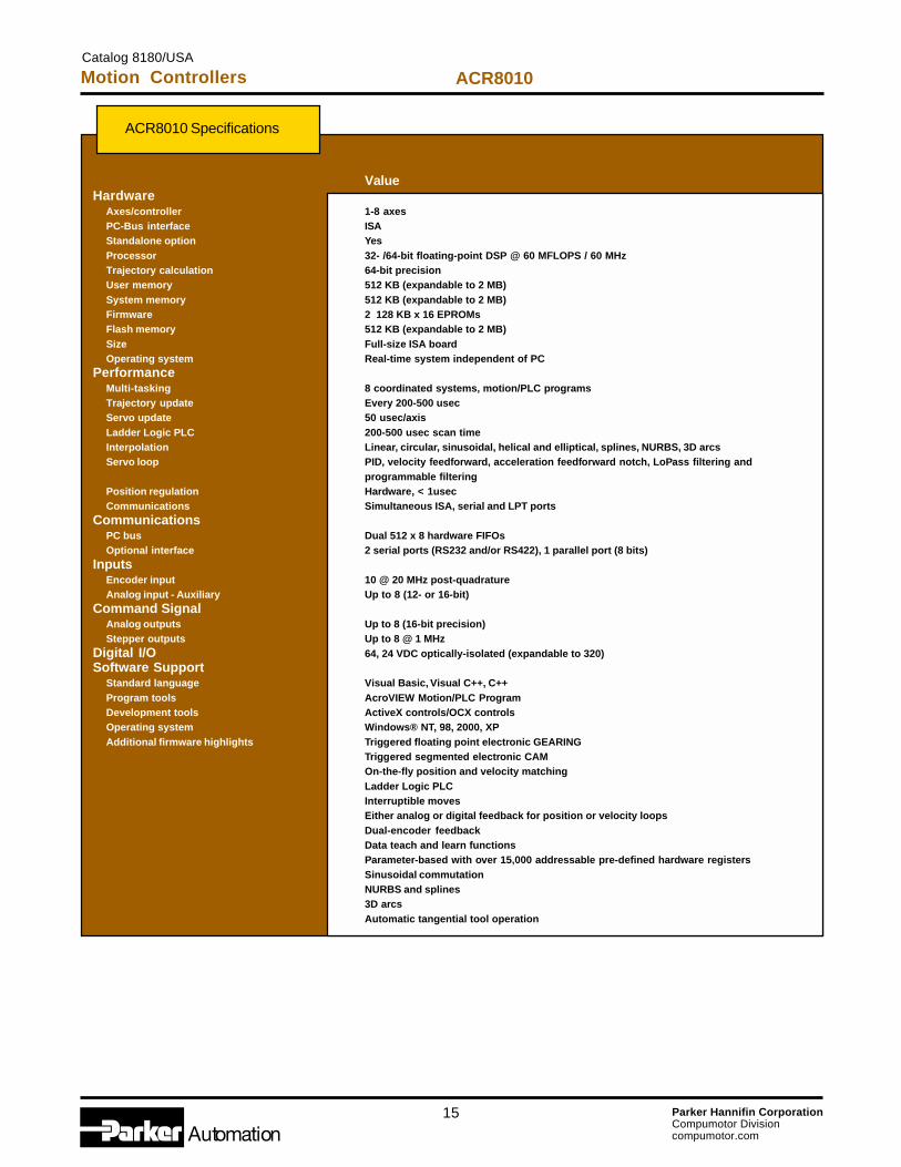
ACR8010 Specifications
ValueHardware
Axes/controller 1-8 axesPC-Bus interface ISAStandalone option YesProcessor 32- /64-bit floating-point DSP @ 60 MFLOPS / 60 MHzTrajectory calculation 64-bit precisionUser memory 512 KB (expandable to 2 MB)System memory 512 KB (expandable to 2 MB)Firmware 2 128 KB x 16 EPROMsFlash memory 512 KB (expandable to 2 MB)Size Full-size ISA boardOperating system Real-time system independent of PC
PerformanceMulti-tasking 8 coordinated systems, motion/PLC programsTrajectory update Every 200-500 usecServo update 50 usec/axisLadder Logic PLC 200-500 usec scan timeInterpolation Linear, circular, sinusoidal, helical and elliptical, splines, NURBS, 3D arcsServo loop PID, velocity feedforward, acceleration feedforward notch, LoPass filtering and
programmable filteringPosition regulation Hardware, < 1usecCommunications Simultaneous ISA, serial and LPT ports
CommunicationsPC bus Dual 512 x 8 hardware FIFOsOptional interface 2 serial ports (RS232 and/or RS422), 1 parallel port (8 bits)
InputsEncoder input 10 @ 20 MHz post-quadratureAnalog input - Auxiliary Up to 8 (12- or 16-bit)
Command SignalAnalog outputs Up to 8 (16-bit precision)Stepper outputs Up to 8 @ 1 MHz
Digital I/O 64, 24 VDC optically-isolated (expandable to 320)Software Support
Standard language Visual Basic, Visual C++, C++Program tools AcroVIEW Motion/PLC ProgramDevelopment tools ActiveX controls/OCX controlsOperating system Windows® NT, 98, 2000, XPAdditional firmware highlights Triggered floating point electronic GEARING
Triggered segmented electronic CAMOn-the-fly position and velocity matchingLadder Logic PLCInterruptible movesEither analog or digital feedback for position or velocity loopsDual-encoder feedbackData teach and learn functionsParameter-based with over 15,000 addressable pre-defined hardware registersSinusoidal commutationNURBS and splines3D arcsAutomatic tangential tool operation
Catalog 8180/USA
Motion Controllers ACR8010

16 Parker Hannifin CorporationCompumotor Divisioncompumotor.com
ACR2000 Specifications
ValueHardware
Axes/controller 1-4 axesPC-Bus interface ISAStandalone option YesProcessor 32- /64-bit floating-point DSP @ 50 MFLOPS / 50 MHzTrajectory calculation 64-bit precisionUser memory 512 KBSystem memory 512 KBFirmware 2 128 K x 16 EPROMsFlash memory 512 KBSize Half-size ISA boardOperating system Real-time system independent of PC
PerformanceMulti-tasking 8 coordinated systems, motion/PLC programsTrajectory update Every 200-500 usecServo update 50 usec/axisLadder Logic PLC 200-500 usec scan timeInterpolation Linear, circular, sinusoidal, helical and elliptical, splines, NURBS, 3D arcsServo loop PID, velocity feedforward, acceleration feedforward notch, LoPass filtering and
programmable filteringPosition regulation Hardware, < 1usecCommunications Simultaneous ISA, serial and LPT ports
CommunicationsPC bus Dual 512 x 8 hardware FIFOsStandalone 2 serial ports (RS232 and/or RS422), 1 parallel port (8 bits)Protocols Binary (PC), string and ASCII
InputsEncoder input 4 (32-bit registers), up to 8 MHz post quadratureAnalog input - Auxiliary Up to 8 (12-bit)
Command SignalAnalog outputs Up to 4 (16-bit precision)Stepper outputs Up to 4 @ 1 MHz
Digital I/O 32, 24 VDC optically-isolated (expandable to 288)Software Support
Standard language Visual Basic, Visual C++, C++Program tools AcroVIEW Motion/PLC ProgramDevelopment tools ActiveX controls/OCX controlsOperating system Windows® NT, 98, 2000, XPAdditional firmware highlights Triggered floating point electronic GEARING
Triggered segmented electronic CAMOn-the-fly position and velocity matchingLadder Logic PLCInterruptible movesEither analog or digital feedback for position or velocity loopsDual-encoder feedbackData teach and learn functionsParameter-based with over 15,000 addressable pre-defined hardware registersSinusoidal commutationNURBS and splines3D arcsAutomatic tangential tool operation
Catalog 8180/USA
Motion Controllers ACR2000

17 Parker Hannifin CorporationCompumotor Divisioncompumotor.com
PC-Based, OEM-Priced
The ACR1500 is Compumotor’s OEM 4-axes PC bus-basedcontroller. The ACR1500 is a PC bus-based card only andoffers no serial or LPT ports as an option. It has the ability torun up to four servo loops with up to four encoders at 8 MHz(post-quadrature). The ACR1500 can also be equipped witheight analog inputs through a 12- or 16-bit analog-to-digitalconverter and introduce these inputs into the servo loop.Because of the modular output design of the ACR family, it ispossible to have two axes of servo with two axes of stepperson the same controller or all axes of one type. Unlike othermembers of the Compumotor Acroloop controller line, theACR1500 utilizes a 16-bit bus, which reduces cost dramati-cally. With this feature, the ACR1500 provides a high level ofcontrol at roughly half the cost! All of Compumotor’s Acroloopproducts utilize the same system software and programminglanguage; this assures users complete flexibility in upgradingtheir hardware while maintaining their investment in programdevelopment. The ACR1500 is Compumotor’s answer to affordable, high-performance control in a standalone package when low cost,real-time speed and ease of programming are most needed.
ACR 1500 Exclusives
• 4 axes of servo or stepper control• 40 MFLOPS floating-point DSP• 4 encoder inputs at 8 MHz (post-quadrature)• User and system memory 128 KB standard• 48 TTL I/O with an industry standard Opto 22, 50-pin connector• Low-cost 16-bit bus• High performance at a low cost
ACR1500 Ordering
Motion ControllersCatalog 8180/USA
ACR1500
Higher-PerformancePCI Version
Coming Soon

18 Parker Hannifin CorporationCompumotor Divisioncompumotor.com
ACR1500 Specifications
ValueHardware
Axes/controller 1-4 axesPC-Bus interface ISAStandalone option NAProcessor 32- /64-bit floating-point DSP @ 40 MFLOPS / 40 MHzTrajectory calculation 64-bit precisionUser memory 128 KBSystem memory 128 KBFirmware 256 KB x 16 EPROMFlash memory 128 KBSize Half-size ISA boardOperating system Real-time system independent of PC
PerformanceMulti-tasking 8 coordinated systems, motion/PLC programsTrajectory update Every 200-750 usecServo update 75 usec/axisLadder Logic PLC 200-750 usec scan timeInterpolation Linear, circular, sinusoidal, helical and elliptical, splines, NURBS, 3D arcsServo loop PID, velocity feedforward, acceleration feedforward notch, LoPass filtering and
programmable filteringPosition regulation Hardware, < 1usecCommunications ISA
CommunicationsPC bus Dual 512 x 8 hardware, FIFOsOptional interface NAProtocols Binary (PC), string and ASCII
InputsEncoder input 4 (32-bit registers) up to 8 MHz post-quadratureAnalog input - Auxiliary Up to 8 (12- or 16-bit)
Command SignalAnalog outputs Up to 4 (16-bit precision)Stepper outputs Up to 4 @ 1 MHz
Digital I/O 48 Opto 22-compatible, programmable as inputs or outputs in groups of 8Software Support
Standard language Visual Basic, Visual C++, C++Program tools AcroVIEW Motion/PLC ProgramDevelopment tools ActiveX controls/OCX controlsOperating system Windows® NT, 98, 2000, XPAdditional firmware highlights Triggered floating point electronic GEARING
Triggered segmented electronic CAMOn-the-fly position and velocity matchingLadder Logic PLCInterruptible movesEither analog or digital feedback for position or velocity loopsDual-encoder feedbackData teach and learn functionsParameter-based with over 15,000 addressable pre-defined hardware registersSinusoidal commutationAutomatic tangential tool operation
Catalog 8180/USA
Motion Controllers ACR1500

19 Parker Hannifin CorporationCompumotor Divisioncompumotor.com
2-Axes, StandaloneControlThe ACR1200 is Compumotor’s OEM two-axes standalonecontroller. The ACR1200 is a standalone controller card onlyand offers no PC port as an option. It comes with two serialports–RS232 and RS422–and has the ability to run two servoloops with up to three encoders at 20 MHz. It can also beequipped with eight analog inputs through a 12- or 16-bitanalog/digital converter and introduce these inputs into theservo loop. Because of the modular design of our outputs, it ispossible to control 2 servo or 2 stepper axes on the samecontroller. This level of control has previously not been availableat this price. All of Compumotor’s Acroloop products utilize thesame system software and programming language; thisassures users complete flexibility in upgrading their hardwarewhile maintaining their investment in program development. The ACR1200 is Compumotor’s answer to affordable, high-performance, standalone control when low cost, real-timespeed and ease of programming are most needed.
ACR 1200 Exclusives
• 2 axes of servo or stepper control• 40 MFLOPS floating-point DSP• Up to 3 encoder inputs at 20 MHz• Standard user and system memory of 128 KB each• Encoder loss and encoder fault protection• High performance at a low cost• Standard 32 optically isolated, 24 VDC I/O (expandable to 160 optically isolated, 24 VDC I/O)
ACR1200 Ordering
Motion ControllersCatalog 8180/USA
ACR1200

20 Parker Hannifin CorporationCompumotor Divisioncompumotor.com
ACR1200 Specifications
ValueHardware
Axes/controller 2 axesPC-Bus interface NA (standalone only)Standalone option YesProcessor 32- /64-bit floating-point DSP @ 40 MFLOPS / 40 MHzTrajectory calculation 64-bit precisionUser memory 128 KBSystem memory 128 KBFirmware 2 128 KB x 16 EPROMSFlash memory 128 KBSize 8” W x 5” HOperating system Real-time system independent of PC
PerformanceMulti-tasking 8 coordinated systems, motion/PLC programsTrajectory update Every 200-750 usecServo update 75 usec/axisLadder Logic PLC 200-750 usec scan timeInterpolation Linear, circular, sinusoidal, helical and elliptical, splines, NURBS, 3D arcsServo loop PID, velocity feedforward, acceleration feedforward notch, LoPass filtering and
programmable filteringPosition regulation Hardware, < 1usecCommunications Simultaneous, serial ports
CommunicationsPC bus NAOptional interface 2 serial ports (RS232 and/or RS422)Protocols String and ASCII
InputsEncoder input 3 (32-bit registers), up to 20 MHz post quadratureAnalog input - Auxiliary Up to 8 (12- or 16-bit)
Command SignalAnalog outputs Up to 2 (16-bit precision)Stepper outputs Up to 2 @ 1 MHz
Digital I/O 32, 24 VDC optically-isolated (expandable to 160)Software Support
Standard language Visual Basic, Visual C++, C++Program tools AcroVIEW Motion/PLC ProgramDevelopment tools ActiveX controls/OCX controlsOperating system Windows® NT, 98, 2000, XPAdditional firmware highlights Triggered floating point electronic GEARING
Triggered segmented electronic CAMOn-the-fly position and velocity matchingLadder Logic PLCInterruptible movesEither analog or digital feedback for position or velocity loopsDual-encoder feedbackData teach and learn functionsParameter-based with over 15,000 addressable pre-defined hardware registersSinusoidal commutationNURBS and splines3D arcsAutomatic tangential tool operation
Catalog 8180/USA
Motion Controllers ACR1200

21 Parker Hannifin CorporationCompumotor Divisioncompumotor.com
Motion ControllersCatalog 8180/USA
AcroView
Diagnostic andProgramming ToolAcroView is a powerful code-development tool that assists theuser of ACR family products in programming, debugging andcommissioning their application. Several features are incorpo-rated to assist both the novice and expert users in developingcode. Code development begins with the setup wizard, whichquickly and easily guides the user through the setup andconfiguration of the ACR controller. Using the tuning tool alongwith the built-in oscilloscope function makes servo tuning asnap. Next, the program editor and ladder editor tools allowstraightforward development of both motion and I/O applicationcode. Finally, the diagnostic tools, included with AcroView,permit easy troubleshooting and optimization of the code toensure the highest level of performance and reliability whenusing the ACR family of control products.
AcroView Features
• PC-bus or serial connection support• Configuration wizard• Tuning tool• Built-in oscilloscope• Structured text program editor• Ladder logic program editor• Real-time terminal interface• Servo loop diagnostic tool• CPU utilization tool
22 Parker Hannifin CorporationCompumotor Divisioncompumotor.com
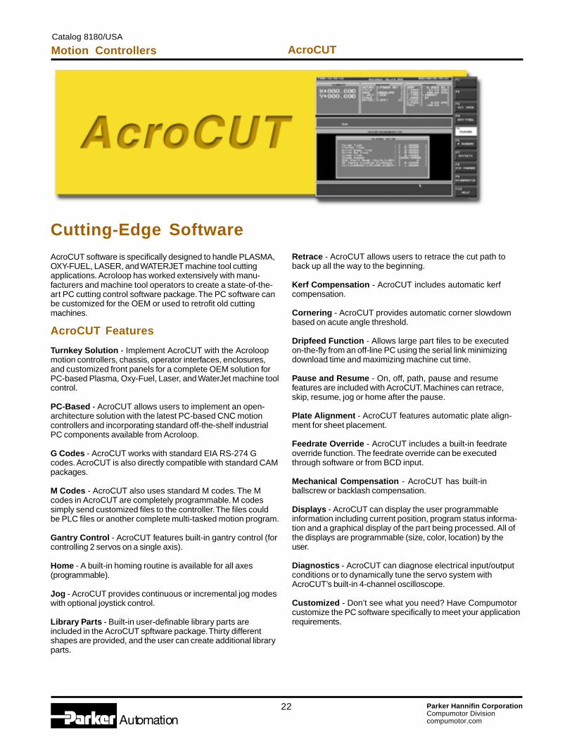
Cutting-Edge SoftwareAcroCUT software is specifically designed to handle PLASMA,OXY-FUEL, LASER, and WATERJET machine tool cuttingapplications. Acroloop has worked extensively with manu-facturers and machine tool operators to create a state-of-the-art PC cutting control software package. The PC software canbe customized for the OEM or used to retrofit old cuttingmachines.
AcroCUT Features
Turnkey Solution - Implement AcroCUT with the Acroloopmotion controllers, chassis, operator interfaces, enclosures,and customized front panels for a complete OEM solution forPC-based Plasma, Oxy-Fuel, Laser, and WaterJet machine toolcontrol.
PC-Based - AcroCUT allows users to implement an open-architecture solution with the latest PC-based CNC motioncontrollers and incorporating standard off-the-shelf industrialPC components available from Acroloop.
G Codes - AcroCUT works with standard EIA RS-274 Gcodes. AcroCUT is also directly compatible with standard CAMpackages.
M Codes - AcroCUT also uses standard M codes. The Mcodes in AcroCUT are completely programmable. M codessimply send customized files to the controller. The files couldbe PLC files or another complete multi-tasked motion program.
Gantry Control - AcroCUT features built-in gantry control (forcontrolling 2 servos on a single axis).
Home - A built-in homing routine is available for all axes(programmable).
Jog - AcroCUT provides continuous or incremental jog modeswith optional joystick control.
Library Parts - Built-in user-definable library parts areincluded in the AcroCUT spftware package. Thirty differentshapes are provided, and the user can create additional libraryparts.
Retrace - AcroCUT allows users to retrace the cut path toback up all the way to the beginning.
Kerf Compensation - AcroCUT includes automatic kerfcompensation.
Cornering - AcroCUT provides automatic corner slowdownbased on acute angle threshold.
Dripfeed Function - Allows large part files to be executedon-the-fly from an off-line PC using the serial link minimizingdownload time and maximizing machine cut time.
Pause and Resume - On, off, path, pause and resumefeatures are included with AcroCUT. Machines can retrace,skip, resume, jog or home after the pause.
Plate Alignment - AcroCUT features automatic plate align-ment for sheet placement.
Feedrate Override - AcroCUT includes a built-in feedrateoverride function. The feedrate override can be executedthrough software or from BCD input.
Mechanical Compensation - AcroCUT has built-inballscrew or backlash compensation.
Displays - AcroCUT can display the user programmableinformation including current position, program status informa-tion and a graphical display of the part being processed. All ofthe displays are programmable (size, color, location) by theuser.
Diagnostics - AcroCUT can diagnose electrical input/outputconditions or to dynamically tune the servo system withAcroCUT’s built-in 4-channel oscilloscope.
Customized - Don’t see what you need? Have Compumotorcustomize the PC software specifically to meet your applicationrequirements.
Motion ControllersCatalog 8180/USA
AcroCUT
23 Parker Hannifin CorporationCompumotor Divisioncompumotor.com
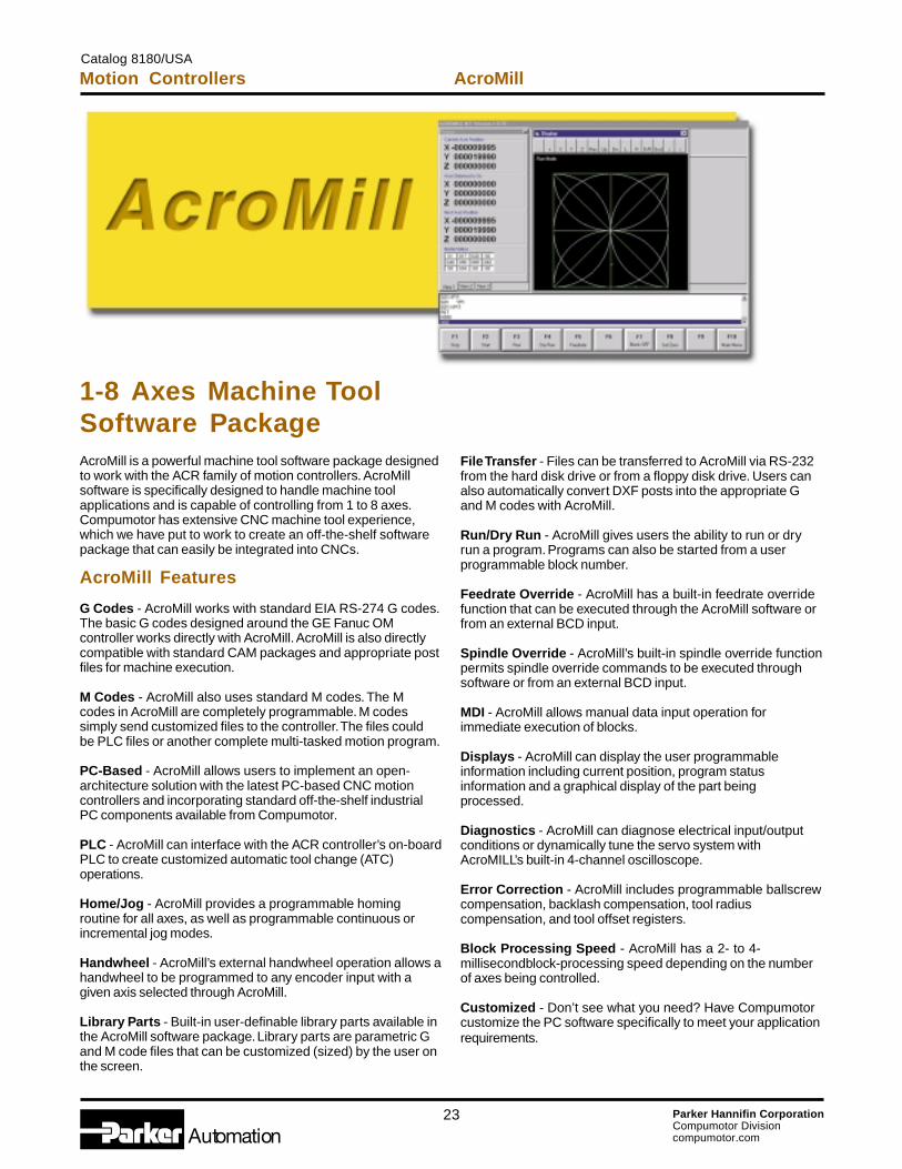
1-8 Axes Machine ToolSoftware PackageAcroMill is a powerful machine tool software package designedto work with the ACR family of motion controllers. AcroMillsoftware is specifically designed to handle machine toolapplications and is capable of controlling from 1 to 8 axes.Compumotor has extensive CNC machine tool experience,which we have put to work to create an off-the-shelf softwarepackage that can easily be integrated into CNCs.
AcroMill Features
G Codes - AcroMill works with standard EIA RS-274 G codes.The basic G codes designed around the GE Fanuc OMcontroller works directly with AcroMill. AcroMill is also directlycompatible with standard CAM packages and appropriate postfiles for machine execution.
M Codes - AcroMill also uses standard M codes. The Mcodes in AcroMill are completely programmable. M codessimply send customized files to the controller. The files couldbe PLC files or another complete multi-tasked motion program.
PC-Based - AcroMill allows users to implement an open-architecture solution with the latest PC-based CNC motioncontrollers and incorporating standard off-the-shelf industrialPC components available from Compumotor.
PLC - AcroMill can interface with the ACR controller’s on-boardPLC to create customized automatic tool change (ATC)operations.
Home/Jog - AcroMill provides a programmable homingroutine for all axes, as well as programmable continuous orincremental jog modes.
Handwheel - AcroMill’s external handwheel operation allows ahandwheel to be programmed to any encoder input with agiven axis selected through AcroMill.
Library Parts - Built-in user-definable library parts available inthe AcroMill software package. Library parts are parametric Gand M code files that can be customized (sized) by the user onthe screen.
File Transfer - Files can be transferred to AcroMill via RS-232from the hard disk drive or from a floppy disk drive. Users canalso automatically convert DXF posts into the appropriate Gand M codes with AcroMill.
Run/Dry Run - AcroMill gives users the ability to run or dryrun a program. Programs can also be started from a userprogrammable block number.
Feedrate Override - AcroMill has a built-in feedrate overridefunction that can be executed through the AcroMill software orfrom an external BCD input.
Spindle Override - AcroMill’s built-in spindle override functionpermits spindle override commands to be executed throughsoftware or from an external BCD input.
MDI - AcroMill allows manual data input operation forimmediate execution of blocks.
Displays - AcroMill can display the user programmableinformation including current position, program statusinformation and a graphical display of the part beingprocessed.
Diagnostics - AcroMill can diagnose electrical input/outputconditions or dynamically tune the servo system withAcroMILL’s built-in 4-channel oscilloscope.
Error Correction - AcroMill includes programmable ballscrewcompensation, backlash compensation, tool radiuscompensation, and tool offset registers.
Block Processing Speed - AcroMill has a 2- to 4-millisecondblock-processing speed depending on the numberof axes being controlled.
Customized - Don’t see what you need? Have Compumotorcustomize the PC software specifically to meet your applicationrequirements.
Motion ControllersCatalog 8180/USA
AcroMill
24 Parker Hannifin CorporationCompumotor Divisioncompumotor.com
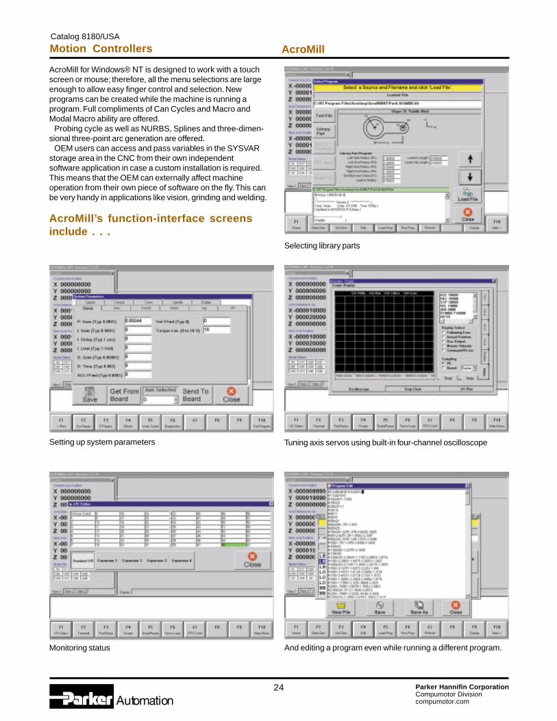
AcroMill for Windows® NT is designed to work with a touchscreen or mouse; therefore, all the menu selections are largeenough to allow easy finger control and selection. Newprograms can be created while the machine is running aprogram. Full compliments of Can Cycles and Macro andModal Macro ability are offered. Probing cycle as well as NURBS, Splines and three-dimen-sional three-point arc generation are offered. OEM users can access and pass variables in the SYSVARstorage area in the CNC from their own independentsoftware application in case a custom installation is required.This means that the OEM can externally affect machineoperation from their own piece of software on the fly. This canbe very handy in applications like vision, grinding and welding.
AcroMill’s function-interface screensinclude . . .
Selecting library parts
Setting up system parameters Tuning axis servos using built-in four-channel oscilloscope
Monitoring status And editing a program even while running a different program.
Catalog 8180/USA
Motion Controllers AcroMill

25 Parker Hannifin CorporationCompumotor Divisioncompumotor.com
Catalog 8180/USA
Motion Controllers Breakout Modules
RBC Features
• Compatible with the ACR2000, ACR8010 and ACR8020• Easy controller connectivity to digital servo and stepper drives• Provides 1 axis connector for each amplifier connection• Simplified system wiring• Screw terminals for digital I/O• 2 serial and 1 parallel port DB connectors• Cables available for all Parker drive families
Breakout Modules
RBD Features
• Compatible with the ACR2000, ACR8010 and ACR8020• General application breakout board• Screw terminals for encode feedback• Screw terminals for digital I/O• 2 serial and 1 parallel port DB connectors• Status LEDs for encoder, digital I/O and communication diagnostics
RBB Features
• Low-cost breakout boards• 4-inch SnapTrack mounting• Individual boards for encoder, digital I/O and communications• Screw terminals for all board signals• DB connectors for communication signals• Status LEDs for diagnostics
26 Parker Hannifin CorporationCompumotor Divisioncompumotor.com
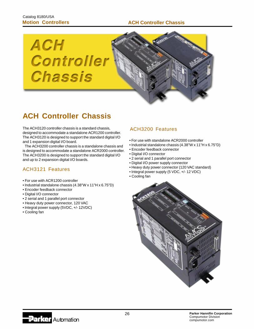
ACH Controller ChassisThe ACH3120 controller chassis is a standard chassis,designed to accommodate a standalone ACR1200 controller.The ACH3120 is designed to support the standard digital I/Oand 1 expansion digital I/O board. The ACH3200 controller chassis is a standalone chassis andis designed to accommodate a standalone ACR2000 controller.The ACH3200 is designed to support the standard digital I/Oand up to 2 expansion digital I/O boards.
ACH3121 Features
• For use with ACR1200 controller• Industrial standalone chassis (4.38”W x 11”H x 6.75”D)• Encoder feedback connector• Digital I/O connector• 2 serial and 1 parallel port connector• Heavy duty power connector, 120 VAC• Integral power supply (5VDC, +/- 12VDC)• Cooling fan
ACH3200 Features
• For use with standalone ACR2000 controller• Industrial standalone chassis (4.38”W x 11”H x 6.75”D)• Encoder feedback connector• Digital I/O connector• 2 serial and 1 parallel port connector• Digital I/O power supply connector• Heavy duty power connector (120 VAC standard)• Integral power supply (5 VDC, +/- 12 VDC)• Cooling fan
Catalog 8180/USA
Motion Controllers ACH Controller Chassis
27 Parker Hannifin CorporationCompumotor Divisioncompumotor.com
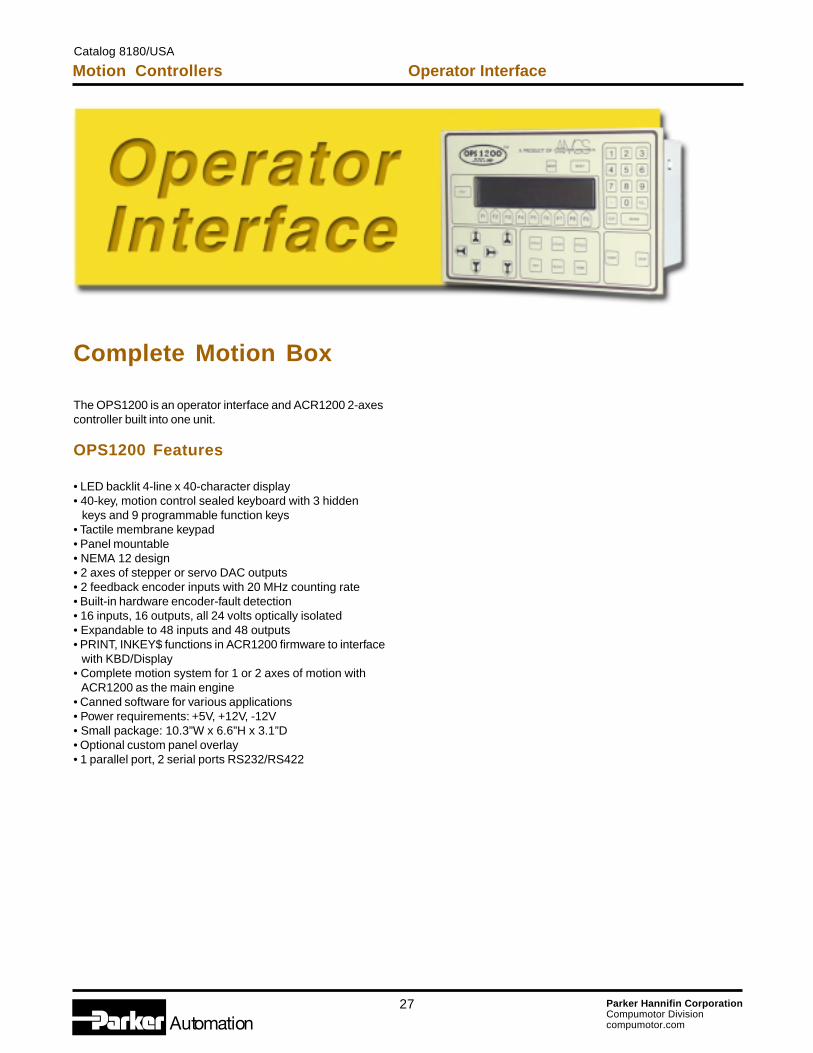
Complete Motion Box
The OPS1200 is an operator interface and ACR1200 2-axescontroller built into one unit.
OPS1200 Features
• LED backlit 4-line x 40-character display• 40-key, motion control sealed keyboard with 3 hidden keys and 9 programmable function keys• Tactile membrane keypad• Panel mountable• NEMA 12 design• 2 axes of stepper or servo DAC outputs• 2 feedback encoder inputs with 20 MHz counting rate• Built-in hardware encoder-fault detection• 16 inputs, 16 outputs, all 24 volts optically isolated• Expandable to 48 inputs and 48 outputs• PRINT, INKEY$ functions in ACR1200 firmware to interface with KBD/Display• Complete motion system for 1 or 2 axes of motion with ACR1200 as the main engine• Canned software for various applications• Power requirements: +5V, +12V, -12V• Small package: 10.3”W x 6.6”H x 3.1”D• Optional custom panel overlay• 1 parallel port, 2 serial ports RS232/RS422
Motion ControllersCatalog 8180/USA
Operator Interface

28 Parker Hannifin CorporationCompumotor Divisioncompumotor.com
Feature-Rich Controller Solves Unique Challenges
hile developing its FASTTM series of fully-automated fiber automation machines, engi-neers at Palomar Photonics Automation (for-merly Axsys Technologies) of Pittsburgh, Penn-sylvania, turned to Parker Acroloop for a highlysophisticated motion control-ler. Beyond the typical re-quirements of a high-speedand PCI-bus platform thatwas powerful enough tohandle multi-axis coordinatedmotion control, they hadsome very specific needsunique to their machine’s ap-plication. Palomar needed the abil-ity to implement multi-dimen-sional inverse kinematics tocontrol their six degrees offreedom fiber-align-ment engine. Fur-thermore, the con-troller needed theability to controlmultiple alignmentengines simulta-neously, creating acontrol system withup to 18 axes of tightly synchronized, high-pre-cision motion.
When choosing a motion con-troller solution, users cannot always predictwhere their application needs are going to beeven a few months down the road in a typicaldesign cycle. Frequently, the needs start atsome base level where most controllers can dothe job. As the application nears completion, itoften has gained functionality that was not inthe original specification. It is common to endup hitting the top end several months into a de-sign cycle because the controller that met theoriginal specification cannot meet the new re-quirements.
Motion ControllersCatalog 8180/USA
Application Story
“It became very clear at an early stage thatthetypical motion controller wasn’t sophisticatedenough to handle our requirements,” says JohnBridgen, applications manager of PalomarPhotonics Automation Division. “The ACR con-
troller quickly became ourcontroller of choice becauseof Parker Acroloop’s exten-sive support, ease of use,technical expertise and will-ingness to work with us onour unique requirements.” Parker Acroloop teamedwith Palomar to create theFeedback Transformationmodule. Optical alignment re-quires precise control in bothCartesian and polar coordi-nate systems; certain feed-
back andm o t i o nelementsare thusnon-lin-ear toe a c ho t h e r ’sw o r kspace.
To correlate the different reference frames re-quired, the team added new input parameters tothe standard firmware set of the ACR controller,which is at the heart of Palomar’s FAST automa-tion products. These parameters enabledPalomar to describe the non-linearities math-ematically and allow the controller to perform thetransformations in real-time to correlate the feed-back signals to motion. Palomar engineers began with alignment astheir primary focus, so they could develop a stan-dard system. “The nice thing about this platform
Continued on next page
W

29 Parker Hannifin CorporationCompumotor Divisioncompumotor.com
balance the production line by controlling all ofthe critical assembly machines.” Repeatability is another advantage. “When youput a device on the system, you can be sure thesystem will find the same optical peak as it did aweek ago,” says Bridgen. Palomar continues toexpand this line on the same basic platform, ratherthan reinventing the wheel. That means provenperformance at lower costs to customers.
is a customer can easily configure it to work witha variety of parts,” says Bridgen. “It is a nice sys-tem for develop-ment, as it relies onwell-defined automa-tion to develop pro-cesses.” Building upon itsstandard platform,Palomar providedthe additional ca-pacities of character-ization and attach-ment of parts all on one turnkey production-gradesystem. This system can load, align and attachan input or output device (e.g., a planar light cir-cuit) to a fiber or array of fibers. It can align tosuch a device in less than two minutes, from partload to peak power to final attach. It increasesquality and saves time. “Doing the same job byhand would take at least an hour under the bestof conditions,” adds Mike Formica, vice president/general manager. That kind of speed increase addresses the pro-
duction bottle-neck problemsthat opticalalignment pro-cesses experi-ence when anupstream wirebonder ma-chine is clippingalong at 10bonds per sec-ond and fre-
quently runs out of parts. This equipment isn’t acomplete cure, but it is a 30-fold improvement.“We’re working on ways to increase speed evenfurther,” says Bridgen. “Because we also manu-facture die bonders and wire bonders, we can
Another key feature of Parker Acroloop’s ACRcontroller for this application is high-speed servoloop closure. These high-speed loops run at100usec for an eight-axes coordinated group, en-abling the FAST products to make the real-timetrajectory corrections necessary for high-speedoptical fiber alignment. The standard dual-portedRAM, 32-bit wide PCI format, true multi-threadcommunication and advanced onboard PLC ca-pability were critical in coordinating control of thiscomplex machine. These elements are controlled seamlessly,largely in part to the ACR’s high flexibility and pow-erful features. “Parker Acroloop’s aggressive product devel-opment schedule and willingness to implementnew features makes it obvious that they are com-mitted to providing the industry’s most advancedproducts,” says Bridgen. “They have been, andwill continue to be, a strong partner to us. Thesuccess of our project is built on the success ofour suppliers, and Parker Acroloop has been noexception.”
“The success of our project isbuilt on the success of our
suppliers, and Parker Acroloop
has been no exception.”
– John Bridgen, applications manager, Palomar Photonics Automation Division
Feature-Rich Controller, continued
Catalog 8180/USAMotion Controllers Application Story
30 Parker Hannifin CorporationCompumotor Divisioncompumotor.com
The items described in this documentare hereby offered for sale at pricesto be established by Parker HannifinCorporation, its subsidiaries and itsauthorized distributors. This offer andits acceptance by any customer(“Buyer”) shall be governed by all ofthe following Terms and Conditions.Buyer’s order for any item describedin this document, whencommunicated to Parker HannifinCorporation, its subsidiary or anauthorized distributor (“Seller”) orallyor in writing, shall constituteacceptance of this offer.
1. Terms and Conditions of Sale:All descriptions, quotations,proposals, offers, acknowledgments,acceptances and sales of Seller’sproducts are subject to and shall begoverned exclusively by the termsand conditions stated herein. Buyer’sacceptance of any offer to sell islimited to these terms and conditions.Any terms or conditions in additionto, or inconsistent with those statedherein, proposed by Buyer in anyacceptance of any offer by Seller, arehereby objected to. No suchadditional, different or inconsistentterms and conditions shall becomepart of the contract between Buyerand Seller unless expressly acceptedin writing by Seller. Seller’sacceptance of any offer to purchaseby Buyer is expressly conditionalupon Buyer’s assent to all the termsand conditions stated herein,including any terms in addition to, orinconsistent with those contained inBuyer’s offer. Acceptance of Seller’sproducts shall in all events constitutesuch assent.
2. Payment: Payment shall be madeby Buyer net 30 days from the dateof delivery of the items purchasedhereunder. Amounts not timely paidshall bear interest at the rate of 1-1/2% for each month or a portionthereof that Buyer is late in makingpayment. Any claims by Buyer foromissions or shortages in a shipmentshall be waived unless Seller receivesnotice thereof within 30 days afterBuyer’s receipt of the shipment.
3. Delivery: Unless otherwiseprovided on the face hereof, deliveryshall be made FOB Seller’s plant.Regardless of the method of delivery,however, risk of loss shall pass toBuyer upon Seller’s delivery to acarrier. Any delivery dates shown areapproximate only and Seller shallhave no liability for any delays indelivery.
4. Warranty: Seller warrants thatthe hardware sold hereunder shall befree from defects in materialworkmanship for a period of twoyears from the date of shipment toBuyer. Seller warrants that theSOFTWARE will perform substantiallyin accordance with theaccompanying materials for a periodof ninety (90) days from the date ofreceipt. Any implied warranties on theSOFTWARE are limited to ninety (90)
days. This limited warranty gives youspecific legal right. You may haveothers which vary from state to state.Some states do not allow limitationson duration of an implied warranty, sothe above limitation may not apply toyou. This Limited Warranty is void iffailure of the SOFTWARE hasresulted from accident, abuse, ormisapplication. THIS WARRANTYCOMPRISES THE SOLE ANDENTIRE WARRANTY PERTAININGTO ITEMS PROVIDEDHEREUNDER. SELLER MAKESNO OTHER WARRANTY,GUARANTEE, ORREPRESENTATION OF ANY KINDWHATSOEVER. ALL OTHERWARRANTIES, INCLUDING BUTNOT LIMITED TO,MERCHANTABILITY ANDFITNESS FOR PURPOSE,WHETHER EXPRESS, IMPLIED,OR ARISING BY OPERATION OFLAW, TRADE USAGE, ORCOURSE OF DEALING AREHEREBY DISCLAIMED.
NOTWITHSTANDING THEFOREGOING, THERE ARE NOWARRANTIES WHATSOEVER ONITEMS BUILT OR ACQUIREDWHOLLY OR PARTIALLY, TOBUYER’S DESIGNS ORSPECIFICATIONS.
5. Limitation of Remedy:SELLER’S LIABILITY ARISINGFROM OR IN ANY WAYCONNECTED WITH THE ITEMSSOLD OR THIS CONTRACTSHALL BE LIMITEDEXCLUSIVELY TO REPAIR ORREPLACEMENT OF THE ITEMSSOLD OR REFUND OF THEPURCHASE PRICE PAID BYBUYER, AT SELLER’S SOLEOPTION. IN NO EVENT SHALLSELLER BE LIABLE FOR ANYINCIDENTAL, CONSEQUENTIALOR SPECIAL DAMAGES OF ANYKIND OR NATURE WHATSOEVER,INCLUDING BUT NOT LIMITEDTO LOST PROFITS ARISINGFROM OR IN ANY WAYCONNECTED WITH THISAGREEMENT OR ITEMS SOLDHEREUNDER, WHETHERALLEGED TO ARISE FROMBREACH OF CONTRACT,EXPRESS OR IMPLIEDWARRANTY, OR IN TORT,INCLUDING WITHOUTLIMITATION, NEGLIGENCE,FAILURE TO WARN OR STRICTLIABILITY.
6. Changes, Reschedules andCancellations: Buyer may requestto modify the designs orspecifications for the items soldhereunder as well as the quantitiesand delivery dates thereof, or mayrequest to cancel all or part of thisorder; however, no such requestedmodification or cancellation shallbecome part of the contract betweenBuyer and Seller unless accepted bySeller in a written amendment to thisAgreement. Acceptance of any such
requested modification orcancellation shall be at Seller’sdiscretion, and shall be upon suchterms and conditions as Seller mayrequire.
7. Special Tooling: A toolingcharge may be imposed for anyspecial tooling, including withoutlimitation, dies, fixtures, molds andpatterns, acquired to manufactureitems sold pursuant to this contract.Such special tooling shall be andremain Seller’s propertynotwithstanding payment of anycharges therefore by Buyer.
8. Buyer’s Property: Any designs,tools, patterns, materials, drawings,confidential information or equipmentfurnished by Buyer or any other itemswhich become Buyer’s property, maybe considered obsolete and may bedestroyed by Seller after two (2)consecutive years have elapsedwithout Buyer placing an order for theitems which are manufactured usingsuch property. Seller shall not beresponsible for any loss or damage tosuch property while it is in Seller’spossession or control.
9. Taxes: Unless otherwiseindicated on the face hereof, allprices and charges are exclusive ofexcise, sales, use, property,occupational or like taxes which maybe imposed by any taxing authorityupon the manufacture, sale ordelivery of the items sold hereunder.If any such taxes must be paid bySeller or if Seller is liable for thecollection of such tax, the amountthereof shall be in addition to theamounts for the items sold. Buyeragrees to pay all such taxes or toreimburse Seller therefore uponreceipt of its invoice. If Buyer claimsexemption from any sales, use orother tax imposed by any taxingauthority, Buyer shall save Sellerharmless from and against any suchtax, together with any interest orpenalties thereon which may beassessed if the items are held to betaxable.
10. Indemnity for Infringement ofIntellectual Property Rights: Sellershall have no liability for infringementof any patents, trademarks,copyrights, trade dress, trade secretsor similar rights except as provided inthis Part 10. Seller will defend andindemnify Buyer against allegations ofinfringement of U.S. patents, U.S.trademarks, copyrights, trade dressand trade secrets (hereinafter‘Intellectual Property Rights’). Sellerwill defend at its expense and will paythe cost of any settlement ordamages awarded in any actionbrought against Buyer based on anallegation that an item sold pursuantto this contract infringes theIntellectual Property Rights of a thirdparty. Seller’s obligation to defendand indemnify Buyer is contingent onBuyer notifying Seller within ten (10)days after Buyer becomes aware of
such allegations of infringement, andSeller having sole control over thedefense of any allegations or actionsincluding all negotiations forsettlement or compromise. If an itemsold hereunder is subject to a claimthat it infringes the IntellectualProperty Rights of a third party, Sellermay, at its sole expense and option,procure for Buyer the right tocontinue using said item, replace ormodify said item so as to make itnon-infringing, or offer to acceptreturn of said item and return thepurchase price less a reasonableallowance for depreciation.Notwithstanding the foregoing, Sellershall have no liability for claims ofinfringement based on informationprovided by Buyer, or directed toitems delivered hereunder for whichthe designs are specified in whole orpart by Buyer, or infringementsresulting from the modification,combination or use in a system ofany item sold hereunder. Theforegoing provisions of this Part 10shall constitute Seller’s sole andexclusive liability and Buyer’s soleand exclusive remedy forinfringement of Intellectual PropertyRights.
If a claim is based on informationprovided by Buyer or if the design foran item delivered hereunder isspecified in whole or in part by Buyer,Buyer shall defend and indemnifySeller for all costs, expenses orjudgments resulting from any claimthat such item infringes any patent,trademark, copyright, trade dress,trade secrets or any similar right.
11. Force Majeure: Seller does notassume the risk of and shall not beliable for delay or failure to performany of Seller’s obligations by reasonof circumstances beyond thereasonable control of Seller(hereinafter "Events of ForceMajeure"). Events of Force Majeureshall include without limitation,accidents, acts of God, strikes orlabor disputes, acts, laws, rules orregulations of any government orgovernment agency, fires, floods,delays or failures in delivery ofcarriers or suppliers, shortages ofmaterials and any other causebeyond Seller’s control.
12. Entire Agreement/GoverningLaw: The terms and conditions setforth herein, together with anyamendments, modifications and anydifferent terms or conditionsexpressly accepted by Seller inwriting, shall constitute the entireAgreement concerning the itemssold, and there are no oral or otherrepresentations or agreements whichpertain thereto. This Agreement shallbe governed in all respects by the lawof the State of Ohio. No actionsarising out of the sale of the itemssold hereunder or this Agreementmay be brought by either party morethan two (2) years after the cause ofaction accrues.
Catalog 8180/USA
Offer of Sale
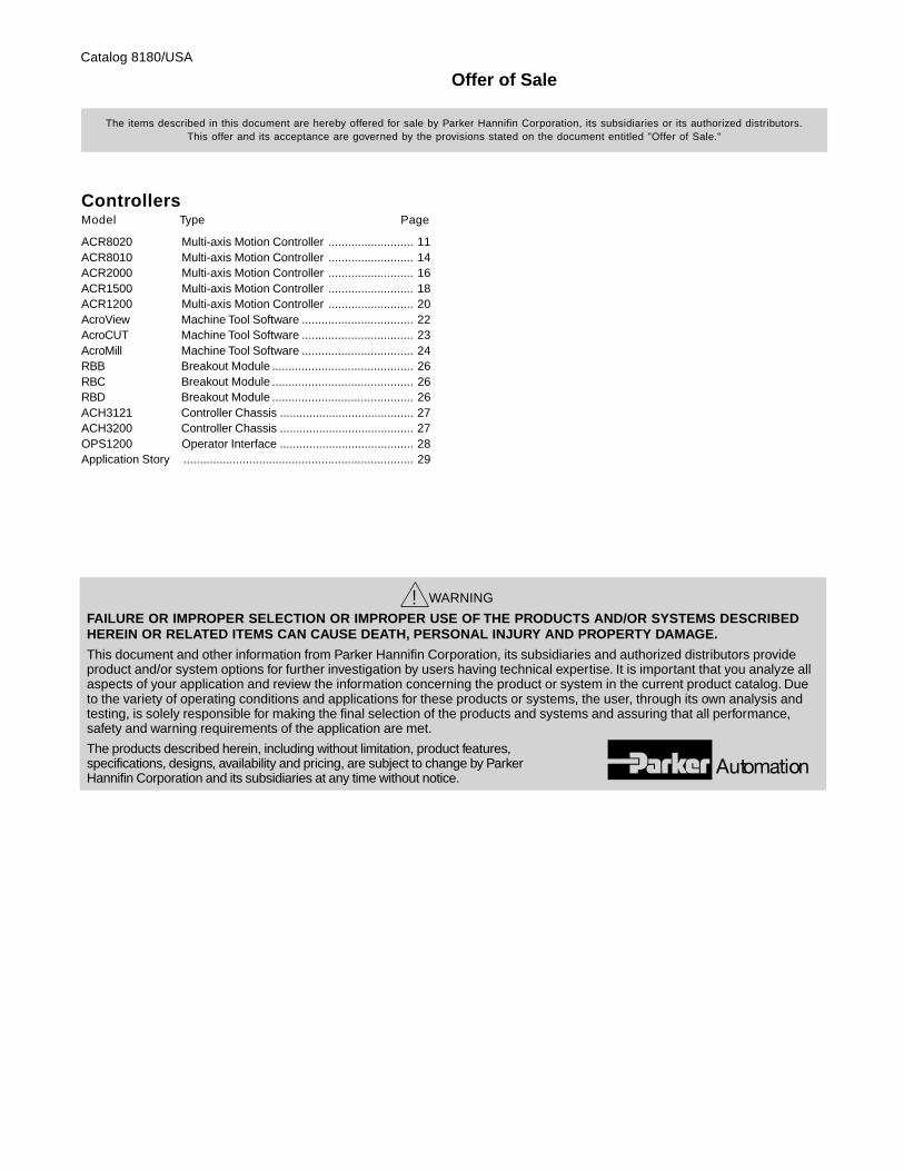
ControllersModel Type Page
ACR8020 Multi-axis Motion Controller .......................... 11ACR8010 Multi-axis Motion Controller .......................... 14ACR2000 Multi-axis Motion Controller .......................... 16ACR1500 Multi-axis Motion Controller .......................... 18ACR1200 Multi-axis Motion Controller .......................... 20AcroView Machine Tool Software .................................. 22AcroCUT Machine Tool Software .................................. 23AcroMill Machine Tool Software .................................. 24RBB Breakout Module ........................................... 26RBC Breakout Module ........................................... 26RBD Breakout Module ........................................... 26ACH3121 Controller Chassis ......................................... 27ACH3200 Controller Chassis ......................................... 27OPS1200 Operator Interface ......................................... 28Application Story ...................................................................... 29
The items described in this document are hereby offered for sale by Parker Hannifin Corporation, its subsidiaries or its authorized distributors.This offer and its acceptance are governed by the provisions stated on the document entitled "Offer of Sale."
! WARNING
FAILURE OR IMPROPER SELECTION OR IMPROPER USE OF THE PRODUCTS AND/OR SYSTEMS DESCRIBEDHEREIN OR RELATED ITEMS CAN CAUSE DEATH, PERSONAL INJURY AND PROPERTY DAMAGE.
This document and other information from Parker Hannifin Corporation, its subsidiaries and authorized distributors provideproduct and/or system options for further investigation by users having technical expertise. It is important that you analyze allaspects of your application and review the information concerning the product or system in the current product catalog. Dueto the variety of operating conditions and applications for these products or systems, the user, through its own analysis andtesting, is solely responsible for making the final selection of the products and systems and assuring that all performance,safety and warning requirements of the application are met.
The products described herein, including without limitation, product features,specifications, designs, availability and pricing, are subject to change by ParkerHannifin Corporation and its subsidiaries at any time without notice.
Catalog 8180/USA
Offer of Sale