Embed Size (px)
Citation preview

The ACP Process™ Applied to the FutureSteelVehicle Project:The Future of Product Design and Development
Akbar Farahani, Ph.D, ETA Inc.Jody Shaw, U. S. Steel
Marc Lambriks, M.Sc., Tata SteelPaul Dolan ETA Inc.
Hamed Sharifi ETA Inc.
ABSTRACTWorldAutoSteel launched Phase 2 of its FutureSteelVehicle programme (FSV) with the aim to helpautomakers optimise steel body structures for electrified vehicles. The Phase 2 objective is to developdetailed design concepts and fully optimise a radically different body structure for a compact BatteryElectric Vehicle (BEV) in production in the 2015-2020 timeframe. This paper will provide an overview ofthe product design methodology and how it was applied to WorldAutoSteel FutureSteelVehicle (FSV)program and result in 35% BIW mass reduction and how it has continued to evolve with each application.
The Accelerated Concept to Product (ACP) Process™ was applied in this project. The ACP Process™ isa proprietary, performance-driven, holistic product design development method, which is based on designoptimization. ACP incorporates the use of multiple CAE tools in a systematic process to generate theoptimal design solution. The ACP Process™ is a methodology that provides solutions, which address thechallenges facing the modern product development environment. It achieves this by synchronizing theindividual facets of the product development process, resulting in an overall reduction in developmentcosts and time to market. Material selection and utilization, product performance requirements andmanufacturing and assembly processes are all considered as early as possible in the design cycle. Theresulting design offers a robust and highly efficient solution; which when combined with the strength anddesign flexibility of Advanced High Strength Steel (AHSS) or other materials; facilitates significant massreduction for the final design.
For the development of a vehicle structure, the methodology offers four key benefits, including ademonstrated capability to reduce product development costs by 40%, reduce product mass by 25% andmore, improve product performance (stiffness, durability, NVH, crash/safety, durability) as well as improvefuel efficiency based on the mass reduction results.
The paper will further disclose the results of the FSV programme, detailing steel body structure conceptsfor the aforementioned vehicles that meet aggressive mass targets of 190 kg, while meeting 2015-2020crash performance objectives as well as total life cycle Greenhouse Gas emissions targets. FSV’s steelportfolio, including over 20 different AHSS grades representing materials expected to be commerciallyavailable in the 2015 – 2020 technology horizon, is utilised during the material selection process with theaid of full vehicle analysis to determine material grade and thickness optimisation. Achievement of suchaggressive weight reduction with steel will set a new standard for vehicle design approaches for thefuture.
Radically different powertrains, such as the BEV and the PHEV proposed for FutureSteelVehicle, andtheir related systems make new demands for increasingly efficient body components to handle the newloads. This will require innovative use of AHSS grades and steel technologies to develop structures thatare stronger, leaner, greener and affordable. The presentation will explain the “state of the future” designoptimisation process used and feature the aggressive steel concepts for structural subsystemsincorporated into the FSV structure.
INTRODUCTIONThe automotive industry is facing numerous challenges today. The product design and developmentprocess includes multi-dimensional issues, which often contradict each other. A central challenge is theneed for cost reduction to compete in the global market, while continuing to meet all new and existingrequirements for quality and performance.

The cost reduction objective is challenged by a few factors, including aggressive fuel economy andemissions standards. Other factors include new crash safety requirements, increasing customer demandsand expectations for quality and performance and the availability of new energy sources such aselectric/hybrid vehicles, plug-in technologies and fuel cells.
While today’s criteria for a vehicle’s environmental performance stresses fuel economy and tailpipeemissions, a more comprehensive approach is required to address the vehicle’s total carbon footprint.This is accomplished with a Carbon Dioxide Life Cycle Assessment (CO2 LCA) approach that measuresthe carbon dioxide emissions associated with all phases of a vehicle’s life.
The key benefits of ACP Process™ are shown in Figure 1.
Figure 1: ACP Process™ Benefits
These requirements indicate that new approaches are necessary. Over the past 10 years, newtechnologies and techniques have been developed and implemented within industry research projects.The development and availability of some key enablers have also emerged, leading to a new designoptimization based technique referred to as the Accelerated Concept to Product (ACP) Process. ACPviews vehicle development in a completely holistic way. An approach such as this ultimately reduces thenumber of prototypes and tests, thereby reducing overall development costs.
THE ACP PROCESS™In order to most effectively explore the design space (design volume, material and manufacturingprocess), while trying to reduce design cycle times, engineers are now using an automated designmultidiscipline optimization-based process, called the Accelerated Concept to Product (ACP) Process.This process can help them to evaluate hundreds of design concepts, finding a set of acceptable designsolutions that also contain the optimal or near-optimal design solution.
ACP is a holistic design process that investigates the entire design space available to define the mostrobust design solution. The tools within ACP can greatly decrease the time required to identify a set offeasible, or even near-optimal, designs prior to building and testing the first prototype. Moreover, ACP canalso compensate for the limitations of human intuition and provide design engineers with the freedom andpower to seek creative solutions that are not obvious to even the most experienced engineers.

KEY ENABLERS OEM’s and software companies have developed many virtual tools to reduce cost in the product designand development process. Such virtual approaches primarily use Computer Aided Engineering (CAE)methodologies, mostly based on the Finite Element Method (FEM). All these virtual tools or environmentstry to connect Design, CAE and Manufacturing while reducing cost. The ACP Process™ uses severalsoftware tools such as an optimization code, CAD parameterization, Modeling/morphing, FEM solvers(static and crash), pre/post processors and formability/stamping solutions.
The availability of new, fast and low-cost hardware such as the High Performance Cluster (HPC) Systemis another key ingredient for this type of approach to cost reduction.
Another key focus is on the availability of new and advanced manufacturing processes. It can be thoughtof as the road map to achieving more affordable, safer, lighter weight and environmentally friendly vehicle(Figure 2).
Additionally, new advanced materials offer solutions for cost reduction, while addressing mass reductionand the need to meet the latest fuel economy and emissions, such as CAFÉ standards. Aluminum,composite materials and even magnesium are being aggressively investigated for mass reduction withmulti-material solutions, challenging the steel industry to enable additional mass reduction capability withsteel for the vehicle body-in-white (BIW) and closures. This is the new direction in the automotive industryand the FutureSteelVehicle program was initiated by WorldAutoSteel to respond to this challenge.
Product development challenges of this magnitude require a new process that incorporates all of theseenablers implemented at the initial stage of product design and development. Combining these keyenablers with the ACP Process™ has proven that the mass can be reduced by at least 15-20%. Thispaper will describe the ACP Process™ and illustrate how it has been successfully applied to the productdesign and development of two research projects: The Future Generation Passenger Compartment(FGPC) and Future Steel Vehicle (FSV).
Figure 2: ACP Enablers

ACP PROCESS™ METHODOLOGYThe ACP Process™ is a holistic product development process with multi-disciplinary loading based ontopology optimization and geometry, grade and gauge (3G) optimization. Using multiple CAE tools;including modeling tools, application-specific tools, solver technology and optimization solutions; CAE,design and manufacturing are all synchronized. Once an optimal concept is identified, the ACP Process™further generates the design, analyzes it and optimizes it using loading, manufacturing, material and costconstraints. It then outputs Computer Aided Design (CAD) data of an optimized concept design, suitablefor detailed design and manufacturing. Figure 3 illustrates the difference between the conventional andACP Process™ approaches to product development.
Figure 3: Current Product Development & ACP Process ™ Comparison
The process can be applied to product development in two ways:
1. Clean Sheet Product DesignFirst, ACP can be applied for a clean sheet design (development of a brand new product). For this typeof product development, engineers start from A-class surface and occupant space. The WorldAutoSteelFSV project applied the enhanced optimization approach conducted for the pilot project to a full vehiclebody structure while addressing metal forming and assembly capability. FSV addressed electrified vehiclepowertrains, consider a technology horizon of 2020 and set a mass reduction target of 35 percent. Thisaggressive mass target will be achieved by leveraging the advanced steel grades, advanced steelmanufacturing technologies and advanced design optimization using ETA’s ACP Process™ steps 1-4( Figure 4).
2. Product Design RefinementACP can be applied for existing product refinement . In this case, engineers start with a current productdesign, which they intend to update, typically improving the design’s performance, mass and costreduction, while at the same time maintaining the packaging, manufacturing and styling. This is not aclean sheet design and so Step 1 is not required. Step 2 represents the modification of the current designto identify any new load paths and where appropriate refine the existing ones. However, since this isprimarily a refinement of an existing design, Step 3 is not required and thus the ACP Process™ can jumpdirectly Step 4, a detailed 2G definition of the vehicle’s geometry. Step 5 is the final validation andsensitivity study of the optimized design.
Figure 4: ACP Process™ Overview
1. Multi-Disciplinary (MD) Topology Optimization fo r the Vehicle Skeleton

The first stage of the process is to develop and define styling, occupant and packaging requirements.Remaining factors and requirements are then formed around these definitions.
During topology optimization, the goal is to define the BIW of the vehicle. The BIW structure is formedbased on where material is required in the design to withstand the major vehicle loads, such as bodystiffness and crash loads.
The ACP Process™ uses topology software and performs multidisciplinary load representations for allmajor loads that define vehicle architectures (crash and static):
1. Front NCAP2. Front 40% Offset Deformable Barrier (ODB)3. Side Impact (IIHS, FMVSS 214)4. FMVSS NPRM 214 - Pole Impact5. FMVSS 301 (Flat barrier, ODB)6. Torsion & Bending Stiffness
These load cases generate the skeleton of the vehicle. The initial material concentration throughout thevehicle design can identify where potential load paths could exist and is evaluated under multiple loadingconditions [16]. Figure 5 shows a summary of the eight loadcases applied and in the frame the finaloptimized structure for a 30% mass fraction. The percentage mass fraction is defined before theoptimization is started and in this case represents the structure remaining after 70% of the original designvolume had been removed. Typically, the topology optimization is run for a variety of decreasingly smallermass fractions so that the relative importance of the emerging load paths can be ranked against eachother.
The load paths that are found in the vehicle material are then converted into structures. The size andlocation of the sections around the material is then defined. Next, the structures are developed using therequired Geometry, Grade and Gauge (3G) [4,10].
Figure 5: ACP Process™ MD Topology Optimization for the Vehicle Skeleton (FSV)
2. MD Load path Optimization and 3G Design Optimiza tionThe goal of the ACP Process™ is to identify the optimal design solution within the available design space.At the heart of this process is 3G optimization method [1].
The process determines the optimal design solution while under multi-disciplinary loading conditions. Inparallel, load paths, Geometry, Grade and Gauge (3G) are defined based on all of the possible materialavailable. The extent of the design space is defined by three criteria, whose relationship is illustrated inFigure 6[5].
� Design Variables - The combinations of design variables that the ACP Process™ canevaluatea. Loadpath - The position of any given structural memberb. Geometry - The cross-sectional shape of that structure memberc. Grade - The choice of material that the structural member is made ofd. Gauge - The thickness of material that the structural member is made of
It is imperative to use engineering expertise in order to define the design variables and theircorresponding space. One needs to completely understand the effects of applied loads in thesystem and think of possible solutions. The ACP Process™ does not invent rather is consider

solutions within the defined design space, therefore it is strictly dependent on the input that theproduct design development team provides (design space and design variables). A FeasibleDesign is one which meets the required performance of the Design Constraints. It is from thesefeasible designs that the optimal, that is the one that best meets the Design Objective, willemerge.
� Design ConstraintsDesign constraints define the required performance that the design must meet. For example, undermultidisciplinary loading, a design might be required to simultaneously meet a maximum accelerationpulse for the NCAP Front Impact loading, while maintaining a maximum passenger compartment intrusionunder IIHS Front Impact loading. This is a design requirement that places the design responses in directconflict with each other. This fact illustrates one of ACP’s key strengths which is the ability of the processto provide a truly balanced, or optimal, design solution.
� Design ObjectiveThe design objective is the overall goal of the optimization. For example, for the BIW of a vehicle thedesign objective may be the greatest possible structural efficiency, or lightest design solution.
Figure 6: The ACP Design Environment
Figure 6 is a representation of the design environment that the ACP Process™ is working within. The firstaxis defines all possible combinations of the design variables as individual designs. Depending on thetotal design variable count this could result in an enormous number of unique designs. The second axisrepresents the response of each design to the load cases under consideration. Note that from all possibleresponses there is a subset of feasible designs that meet the required design constraints. This is thecontrol group of the ACP Process™, for it is only the feasible designs that are of interest. The third axisrepresents how well each design meets the design objective.
When considering the designs generated by the ACP Process™ it is important to consider the following.
� The ACP Process™ is essentially a Search EngineIn itself the ACP Process™ is unable to “invent”, rather it searches the predefined available design spacefor the best possible solution which meets all of the design constraints
� Optimization EnablersAs noted previously, the ACP Process™ does not “invent”, rather it “balances.” Therefore, when reviewingthe specific design variable selections for a given design it is inappropriate to consider them in isolation.For example, the choice of a particular material grade should not be considered without firstunderstanding the choice of cross-sectional shape and gauge of that component and its relationship to allother components within the structure excited by the same loading condition.
� TargetsThe design constraints define the required performance. The ACP Process™ seeks to find the bestpossible solution with respect to the design objective where it meets the performance goal.
� PerformanceDepending on the freedom that the ACP Process™ is given, the resulting design solutions can be veryunconventional. Notably, each design’s performance has been measured against the design constraintsand so each can confidently be considered a valid design.
Figure 7 shows ACP’s automated process. The system evaluates hundreds of design solutionsautomatically. The process starts with an approximated vehicle FE model, of which geometry isparameterized. This initial geometry begins the process and is evaluated, then new design solutions aregenerated using changes in geometry, grade and gauge (3G optimization). The design team monitors thedesign changes when these new solutions are found. The process continues until the objectives are met(meeting minimum mass and performance targets). Several design solutions can be found and afterfurther study the best design concept is selected [8,9,10].
Figure 7: ACP Process™ – A Fully Automated Process
3. Sub-System Multi-Disciplinary (MD) 3G Holistic O ptimization and Selection of Major MemberManufacturing ProcessAfter the full-vehicle system load path and general section geometry, grade and gauge is determined bythe ACP Process™, manual design modification for high level manufacturability is performed. The fullsystem is ready for detailed design for a selection of manufacturability processes, materials and gauges. To achieve this, the full-system would be decoupled into major load carrying sub-systems which theydefine the characteristics of the vehicle such as front rail and rear longitudinal, shotgun, rocker, B-pillarand side roof rail [1]. The ACP Process™ identifies the optimal design solution within the available designspace and details design variables based on high fidelity 3G optimization for each of sub-systems [2]. Thematerial of each subsystem with its manufacturing process will be the output for the next step of the ACPProcess™ [9,10].
4. Full Vehicle System MD 2G Optimization with Deta iled ManufacturingAfter the major sub-systems are designed by ACP Process™, the components are modified by manualdesign manipulation based on selected manufacturing processes. The new vehicle architecture is thenintegrated into the full-vehicle system based on the ACP selections of materials and manufacturing

processes. A full vehicle BIW and closures structure will be designed in detail (joining, interactions, sub-assemblies) using design specifications and manufacturing evaluations to meet vehicle performancetargets[3].
This resulting design represents the most robust load path, geometry, gauge and grade of the materialson the vehicle.
Since this model can contain inefficiencies due to modifications based on new material choices andmanufacturing processes, multi-disciplinary 2G optimization is performed in this phase. This is done tomake sure that the new design (based on sub-systems) still meets all vehicle performance targets interms of crash, stiffness and low frequency NVH while considering the manufacturing process.
Manufacturability using one step and incremental formability for all the components will be done. Designchanges to remove any manufacturing issues (strain, wrinkling, cracking and thinning). At this stage in the ACP Process™, the expectation is that the designed vehicle system meets all vehicleperformance and a 25 - 30% mass reduction, based on vehicle class and mass targets [8].
5. Confirmations, Validation and Detailed Design fo r ProductionDuring this stage, the engineering team gets confirmation of total design solution, incorporating all loadcases of BIW and closures for durability, crash/safety, NVH and ride and handling. A sensitivity study isdone and minor design modifications are made. The vehicle model is validated virtually and is preparedfor prototyping and testing [8].
ACP PROCESS™ FULL VEHICLE PROGRAM IMPLEMENTATIONACP has been successfully applied to two major full vehicle steel research programs. The first importantsegment of the research was regarding vehicle mass reduction. This project was conducted by theAuto/Steel Partnership (A/SP), as part of the Future Generation Passenger Compartment (FGPC) project.The project demonstrated the feasibility of the approach and it effectiveness at achieving significant massreduction. Also, it demonstrated that this methodology was no longer a “pie-in-the-sky” proposal--it wastruly something that automobile manufacturers could employ immediately.
FGPC PROGRAMIn Future Generation Passenger Compartment (FGPC) Phase 1, completed in 2007 and funded by A/SPmembers and the U.S. Department of Energy, the goal was to develop a lightweight passengercompartment using AHSS. The team developed a conceptual optimization methodology, which realized amass reduction of 30 percent when compared with a typical passenger compartment of the same vehicleclass.
The FGPC Phase 1 donor vehicle was the UltraLight Steel Auto Body - Advanced Vehicle Concepts(ULSAB-AVC). The vehicle packaging was adapted for both a conventional diesel and hydrogen fuel cellpowertrains. The 30 percent reduction was achieved while maintaining compliance with current and future(2015) crash/safety performance, stiffness and durability regulations. A series of sensitivity studies provedthe robustness of the design through its ability to accommodate variations in the vehicle’s curb weight andside impact barrier height [4].
In addition to exceeding the original goal by five percent while maintaining the structural parameters forstiffness and durability, the optimized design actually improved the vehicle’s crashworthiness.
FGPC-Validation, the second phase of the program, began in 2007 as the research group sought to provehow conceptual ideas developed in Phase 1 could be applied to a production vehicle. Using a 2008 OEMdonor production luxury vehicle as the baseline product, the group set out to develop a concept designwith the goal of reducing the passenger compartment’s structural mass by 20 percent.

The results showed that the mass of the passenger compartment structure could be reduced between 15and 20 percent with minimal increased costs. This provides a cost effective solution relative to the non-steel material solutions, which would have significantly increased the costs to achieve this type of massreduction.
The program also proved that advanced joining technology (laser-welding or adhesive bonding) couldincrease the overall mass reduction to 20 percent. Sensitivity studies established the viability of the loadpaths and robustness of the optimized design.
Figures 8 and 9 show the results of the FGPC-Validation study. Figure 8 illustrates the baseline vehicle’smaterial content compared to that of the mass optimized concept solution. Using a preponderance of dualphase, martensitic and boron steels rather than the conventional steel used in the baseline donor modelis one key factor in the mass reduction.
Baseline Vehicle
1%
32%
15%
52%
Mild
HSLA
Dual Phase
Martensite/Boron
Optimized Solution
17% 4%
77%
2%
Optimized Solution
17% 4%
77%
2%
Mild
HSLA
Dual Phase
Martensite/Boron
Figure 1
Material ContentBaseline Vehicle Optimized Concept
Steel GradesBaseline Vehicle
1%
32%
15%
52%
Mild
HSLA
Dual Phase
Martensite/Boron
Optimized Solution
17% 4%
77%
2%
Optimized Solution
17% 4%
77%
2%
Mild
HSLA
Dual Phase
Martensite/Boron
Figure 1
Material ContentBaseline Vehicle Optimized Concept
Steel Grades
Figure 8: FGPC Material Content
Figure 9 shows the passenger compartment’s weight for the baseline model and the two alternativeFGPC solutions. The solution that used advanced joining technology (laser-weld or adhesive bonding)was 20 percent lighter than the baseline.
Cost information shown on Figure 9 demonstrates that material costs are lower for the FGPC solution, butforming costs are substantially higher. Total manufacturing costs for the lowest weight solution arepredicted to be 5 percent higher than the baseline.
Figure 9: FGPC Mass and Cost Reduction
FGPC Validation Phase achieved 15 to 20 percent mass reduction, but could not reach the desired 30percent level while adhering to the manufacturing, packaging and architectural constraints adopted by theproject [5,8].
FSV PROGRAMThe FutureSteelVehicle (FSV) program consists of three phases [16]:
• Phase 1: Engineering Study (2008 - 2009)• Phase 2: Concept Designs (2009 - 2010)
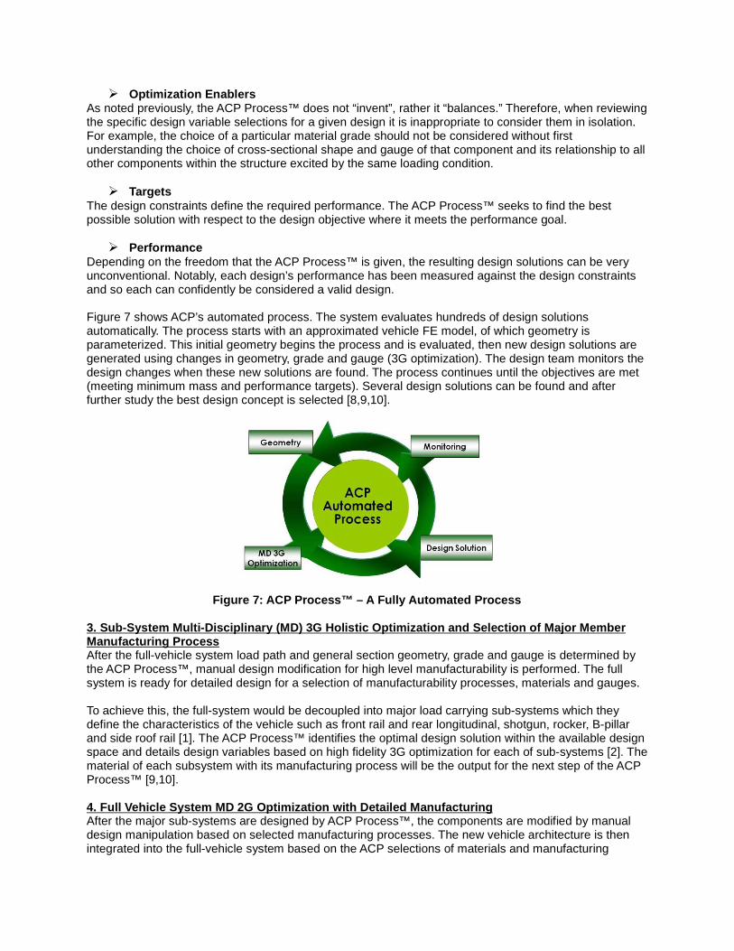
• Phase 3: Demonstration and Implementation (Beyond 2011)
A. Component & Passenger Packaging Study
C. Styling Study
B. Aerodynamic Study
Figure 10: FSV Packaging and StylingThe content of Phase 1 was a comprehensive assessment and identification of advanced powertrains andfuture automotive technology applicable to high-volume vehicle production in the 2015-2020 time frame[11]. The FSV program is currently at the end of Phase 2, designing optimized AHSS / UHSS bodystructures for four vehicles: Battery electric (BEV) and plug-in hybrid electric (PHEV-20) for A/B Classvehicles; and Plug-in hybrid electric (PHEV-40) and fuel cell (FCEV) for C/D class vehicles. This includesthe optimization of multiple solutions for seven different sub-systems: the rocker, B-pillar, roof, rear andfront rails, front upper load path and battery tunnel load path members. The FSV engineering teamrecommended the BEV with a range of 250 km as the focus of the Phase 2 detailed design, as thispowertrain was considered a more challenging design for steel since it is the heaviest powertrain option(Figure 10).
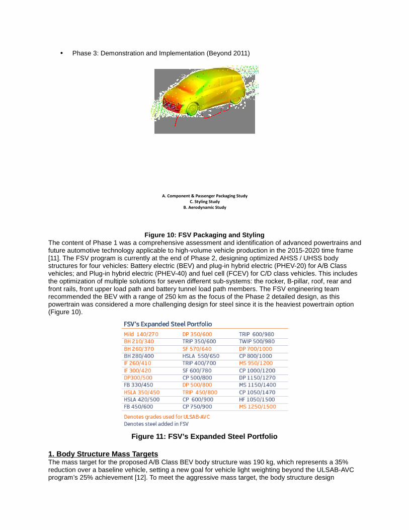
Figure 11: FSV’s Expanded Steel Portfolio
1. Body Structure Mass TargetsThe mass target for the proposed A/B Class BEV body structure was 190 kg, which represents a 35%reduction over a baseline vehicle, setting a new goal for vehicle light weighting beyond the ULSAB-AVCprogram’s 25% achievement [12]. To meet the aggressive mass target, the body structure design

methodology combines an advanced steel materials portfolio (Figure 11), advanced steel manufacturingtechnologies and the above described ACP Process™ and is applied to a clean sheet design targeted atthe BEV powertrain. The SAE Vehicle Innovation Award-winning design optimization process used todevelop structures for FSV has the same energy and resource efficiency objective that mirrors whathappens in nature, creating radically different, non-intuitive architectures optimized for the structure’sfunction within the total system [13]. In addition to traditional technology solution selection criteria thatconsider mass and cost, the FSV program also considers technologies that reduce the total carbonfootprint of the vehicle by applying a life cycle assessment (LCA) approach [14].
2. Phase 2 Design Methodology
2.1. Packaging and Computational Fluid Dynamic Simulation After the Phase 1 technology assessment, studies of powertrain packaging, interior occupant space, ingress/egress
requirements, vision/obscuration, luggage volume requirements, and ergonomic and reach studies of interior
components established the component and passenger package space requirements. An exterior styling was
applied to the packaging, followed by several computational fluid dynamic simulations, resulting in a drag
coefficient of Cd = 0.25 (Figure 12).
Figure 12: BEV packaging theme and aerodynamic stud y
2.2. Topology Optimization As a first step in the ACP Process™, the objective of the topology optimization is to provide aninitial structure based on the available structure package space as shown in Figure 13. The FSVprogram developed this structure by considering three longitudinal load cases, two lateral loadcases, one vertical load case, bending and torsional static stiffnesses. The topology optimizationeliminates elements from a finite element mesh that represents the available structural designspace, i.e. the volume within which structure can exist (Figure 13). The elimination of elementsis based on strain energy, thereby revealing the optimal load paths.
Figure 13: BEV structural design space, topology op timization results and interpretedCAD model
A target reduction or mass fraction is defined as a goal for the optimization. For this analysis,the topology optimization goals were 30%, 20% and 10% mass fractions (Figure 13). With theresults obtained from the topology optimization, the geometry is interpreted into a CAD model(Figure 13) using engineering judgment. This model represents the initial skeleton geometry ofthe FSV and forms the basis of the next step in the optimization process.
2.3. Low Fidelity 3G (Geometry, Grade and Gauge) an d Sub-System Optimization Though the topology optimization was able to provide an initial starting point for the FSV’sgeometry, it is limited by its static approximation of dynamic crash loads and does not consider

grade variations of the sheet metal within the structure. Therefore, the load path optimization ismoved to the dynamic design domain (using LS-DYNA® Finite Element Analysis Software)combined with a multi-discipline optimization program (HEEDS® Multidisciplinary DesignOptimization Program), which also addresses a low fidelity optimization of the major load pathcross-sections, grades and gauges of the body structure. The output is designated the LowFidelity Geometry, Grade and Gauge (LF3G) optimization.
Figure 14: LF3G optimization, reference body struc ture and structural sub-systems
The final FSV body structure attained from the LF3G optimization is shown in Figure 14, whichdoes not represent section shapes that can necessarily be manufactured and assembled norare they structurally efficient from a topography perspective. To create the required referencebody structure, the LF3G body structure was combined with engineering judgement of currentbenchmarked designs (Figure 14). This reference assumes typical manufacturable sections andjoint designs combined with extensive use of AHSS achieving a calculated mass for the sheetsteel baseline (Figure 14) of 218 kg. Based on load path mapping, seven structural sub-systems(Figure 14) were selected for further optimization using a broad bandwidth of manufacturingtechnologies.
2.4. 3G Optimization of Sub-SystemsThe optimization objective was to minimize the mass of each sub-system and simultaneouslymaintain the deformation energy in the sub-systems as that in the full LF3G model for eachrespective load case. The solutions obtained from the structural sub-system multi-discipline 3Goptimization runs had appropriate material strengths and gauges, optimized to give a low masssolution, that met the structural performance targets. These solutions were assessedconsidering the general manufacturing technology guidelines to ensure manufacturability of thesub-system. For example, the rocker sub-system model was optimized with AHSS / UHSS steeltechnologies for four different manufacturing methods (Figure 15). Each of the 12 manufacturinginterpretations for the rocker structure have equivalent in-vehicle performance. Themanufacturing interpretations of each of the sub-systems formed the basis for determining theblank size, blank mass, part mass and the other related manufacturing parameters.

Figure 15: Rocker Solution Alternative Manufacturi ng Scenarios
2.5 BEV Sub-Systems Selection Steel’s flexibility enabled the achievement of a variety of solutions for the selected sub-systems. Withinthis portfolio of solutions are applications that all vehicle manufacturers and segments will find relevant.These solutions demonstrate dramatically reduced mass and GHG emissions in seven optimised sub-system structures, at lower or comparable costs to conventional solutions. The next step in the FSV design process is to select the most appropriate sub-system options from thosedeveloped through the design methodology. The programme engineering team made these decisionsbased on the following factors: � Mass � Cost - A "technical cost modeling" approach was applied to all parts to estimate the subsystemmanufacturing costs � Life Cycle Assessment (LCA) for GHG - An analysis of each sub-system’s impact on the total LCA ofthe vehicle conducted with the UCSB GHG Comparison Model.
Beyond these criteria the selection process considered the technology time horizon to be withinthe 2015-2020 timeframe. It also considered the joining compatibility between the technologies.Hence, the FSV sub-systems recommendations were divided into three categories, based onthe level of difficulty of the manufacturing technology, and the time period during which thesetechnologies would be feasible for high-volume production.
3. Body-in-White Design, Assembly & Performance of FSV BEV
Body-in-white FSVBEV
Benchmark Mass(kg) 290
Target Mass (kg) 190Achieved Mass(kg) 187.7
Table 1: FSV programachievement
3.1 FSV Battery Electric Vehicle final light-weight body-in-white structure
The Battery Electric Vehicle body-in-white (BIW) structure achieved mass savings of 101 kg (-35%) compared to the baseline body structure mass as shown in Table 1. The mass reductionhas been realized through the use of advanced and ultra high-strength steel grades combined

with steel technologies such as roll forming and multi-thickness blanks. Even though there is acost premium associated with the use of higher grade steels, the consequently achieved weightsavings balances the overall costs of manufacturing and assembly. The BEV body-in-whitestructure, the different grades of steel and the steel grade distribution are shown in Figure 16.
Figure 16: FSV BEV body-in-white steel grades used and distribution
4.2 Forming simulation & joining issuesFigure 17 illustrates the different manufacturing technologies implemented for the FSV body-in-white structure. The main technologies include cold stamping of monolithic and laser weldedblanks, hot stamping and roll forming.
Figure 17: FSV body-in-white manufacturing processe s
Single step simulation was done on all the parts of the BIW. Parts that play an important role incrashworthiness like B-pillars, shotguns and roof rails were made through a hot formingprocess. In that case, a single step simulation with IF260/410 material parameters was used.Some parts, which have complicated shapes like front rails, body side outer and rear railsrequire the incremental analysis method for predicting the manufacturing results moreaccurately. In Figure 18, the results of the incremental analysis of the body side outer made withDP600 0.8 mm and BH220 0.6 mm for the rear parts are shown. Although some minor changesare needed, it proves that the stamped component design is safe.
Figure 18: FSV body side outer incremental analysis results

Some of the most common assembly joining techniques were considered. The joiningprocesses selected for the FSV body-in-white assembly were resistance spot welding, laserwelding, laser brazing, roller hemming and adhesive bonding. Figure 19 and Table 2 belowdetail the quantity for each joining technique used:
Spot Welds
Laser Welds
Adhesive
Figure 19: Joining techniques used for FSV BIW asse mbly
Joining Techniques Total Note:- Laser Welds includes: Laser Welding
(Remote), Laser Brazing- Adhesive includes: Structural adhesive
(1-Part Epoxy), Anti-flutter, Hem adhesive
Total number of Spot Welds 1001
Total Length of Laser Welds 87.26 m
Total Length of Adhesive 19.11 m
Table 2: Joining techniques details used for FSV BI W assembly
Specific attention has been paid to the design in order to avoid impossible welding stack-upssuch as mild steel 0.6 mm - mild steel 0.6 mm - PHS 2.0 mm.
4.3 Crash worthiness, stiffness and NVHThe detailed design of the FSV body structure was supported by computer aided engineering(CAE) analysis, to verify the structural performance. The CAE analysis results were comparedto the FSV targets to quantify the performance of the FSV body structure in terms of staticstiffness, crashworthiness and durability. As illustrated in Tables 3 and 4, it can be seen that theFSV body structure meets or surpasses the performance targets.
Analysis Type Target FSV Model Results
US NCAPPeak pulse < 35 g, footwell intrusion <
100 mm
Peak pulse 36.6 g, footwell intrusion 32.3
mm
Euro NCAPPeak pulse (driver side) <35 g, footwell
intrusion < 100 mm
Peak pulse 32.2 g, footwell intrusion 90
mm
FMVSS 301R
Battery should remain protected and
should not contact other parts after the
crash
Battery is protected and there is no
contact with other parts after crash
ECE R32
Battery should remain protected and
should not contact other parts after the
crash
Battery is protected and there is no
contact with other parts after crash
IIHS Side ImpactB-Pillar intrusion with respect to driver
seat centerline ≥ 125 mm136 mm
US SINCAP Side ImpactB-Pillar intrusion with respect to driver
seat centerline ≥ 125 mm215 mm
FMVSS 214 Pole ImpactDoor inner intrusion with respect to
driver seat centerline ≥ 125 mm173 mm
Euro NCAP Pole ImpactDoor inner intrusion with respect to
driver seat centerline ≥ 125 mm169 mm
FMVSS 216a and IIHS
Roof
Driver and passenger side roof structure
should sustain load > 28.2 kN within the
plate movement of 127 mm (FMVSS
216a), > 37.5 kN (IIHS)
Sustains load = 45 kN for driver side, = 43
kN for passenger side
RCAR/IIHS Low Speed Damage is limited to the bumper and There is no damage in components other

Impact crash box than the bumper and crashbox
Table 3: FSV CAE analysis results – Crashworthiness
Analysis Type Target FSV Model Results
Torsion stiffness (kN-m/deg) ≈ 20.0 19.972
Global Modes Target Frequency
Torsion >40 Hz (both modes), separated by
3 Hz
54.8
Vertical bending 60.6
Table 4: FSV CAE analysis results - Stiffness
As an example, see Figure 20 for the Insurance Institute for Highway Safety (IIHS) side impactcrash test setup and results.
Figure 20: IIHS side impact crash test and B-pillar intrusion
A complete noise and vibration analysis has been performed by LMS for FSV at the conceptstage. Measurements were conducted on two small Mitsubishi vehicles that both share thesame body, yet one is equipped with an internal combustion engine and the other with anelectric motor. The outcome was used as a starting point to identify assets and pitfalls of electricmotor noise and draw a set of NVH targets for FSV. Compared to a combustion engine, theelectric motor shows significantly lower sound pressure levels, except for an isolated highfrequency peak heard at high speeds (3500 Hz when the vehicle drives at top speed) which islowered by increased use of acoustic absorbent materials in the motor compartment. For lowand mid frequencies, moderate electric motor forces imply less stringent noise and vibrationdesign constraints and a possibility to reduce the body mass. Finite element simulations at lowand mid frequencies lead to reshaping the suspension mounts, the rear roof, the front headerand the cowl top connection area, each change driving large reductions of noise levels whileadding little to no mass. Damping sheets prove unnecessary. Lighter damping solutions such asvibration damping steels were examined and proved to be successful in the mid frequencyrange. Overall, the change from combustion engine to electric motor is compatible with massreductions and similar or better noise and vibration performances.
CONCLUSIONIn conclusion, by applying the ACP Process™ and incorporating the use of unique optimization tools,advanced materials and advanced manufacturing technology, manufacturers can addresses many of thecurrent product development challenges which face the automotive industry today. � Reduce cost of product design development by 40% in concept and development phase
(referenced to the programs ETA has completed for its clients).� The process has proven to reduce mass by 20% beyond the mass reduction that has previously
been achieved with AHSS – at little or no additional cost. � The ACP Process™ can be used for any product such as vehicle components (closures,
chassis/suspensions, interiors and seat).� Though the ACP Process™ has been applied to mass reduction studies, it can be equally applied
to any other design objective the Product Development Team requires such as cost reduction,reduced carbon footprint etc.

� The ACP Process™ is indifferent to material type.
The FutureSteelVehicle project used the ACP Process™ combined with an expanded portfolio of steelsand manufacturing technologies that foretell the future of steel grades readily available in the 2015 to2020 time frame. The state-of-the-future design methodology used to develop the FSV body structure isat the leading edge of computer-aided optimisation techniques and helped the program to achieve anoptimal mass efficient design. Key achievements are:� Employs state-of-the-future design innovations that exploit steel’s versatility and strength� Achieves 35% BEV body structure mass savings compared to benchmark ICE vehicle� Uses 97% High-Strength (HSS) and Advanced High-Strength Steel (AHSS), of which nearly 50%
is over the 1000 [MPa] strength steels� Enables 5-star safety ratings� Reduces total Lifetime Emissions by nearly 70% compared to ICEg� Reduces mass and emissions at no cost penalty
REFERENCES
1. J.M. Madakacherry, D. Eby, M. B. Isaac, A. Farahani, C. Bruggeman and R. C. Averill “A Process ofDecoupling and Developing Optimized Body Structure for Safety Performance,” “10th European LS-DYNA Conference.” March 18, 2004.
2. D.J. Eby, R.C. Averill, E.D. Goodman and R.S. Sidhu, “Shape Optimization of Crashworthy Structures,” LS-DYNA
User’s Conference, Dearborn, MI, May 20-21, 2002.
3. A. Farahani, R.C. Averill and R. Sidhu, “Design Optimization of Hydroformed Crashworthy Automotive Body
Structures,” CAD-FEM Users’ Meeting, Berlin, Potsdam, Germany, November 12-14, 2003.
4. Auto Steel Partnership, “Future Generation Passenger Compartment”, (FGPC) Phase 1, November 2007
5. Auto Steel Partnership, “Future Generation Passenger Compartment”, (FGPC) Validation, November 2009
6. D Reed, T. Seel, D. Baskin and A Vollmer, “Lightweight Body Section Targeting & Material Selection Process”,
Great Designs In Steel (GDIS) May 2008
7. A. Farahani, J. Shaw, “Future Generation Passenger Compartment” Great Designs in Steel (GDIS), May 2007
8. J.Polewarczyk, “Future Generation Passenger Compartment- Validation Phase”, Great Designs in Steel (GDIS)
May 2009
9. A Farahani, J. Shaw“, Highly Optimized Longitudinal Rail Achieving 45% Mass Reduction”, Great Designs in
Steel (GDIS), May 2009
10. J. Shaw, H. Singh and A. Farahani, “Future Steel Vehicle”, Great Designs in Steel (GDIS) May 2010
11. EDAG AG, (2009). FutureSteelVehicle Phase 1 Engineering Report,www.worldautosteel.org/Projects/Future-Steel-Vehicle/Phase-1-Results-Phase-2-Launch.aspx
12. Porsche Engineering Services, Inc., (2002). ULSAB-AVC (Advanced Vehicle Concepts)Engineering Report, Retrieved from WorldAutoSteel website,www.worldautosteel.org/Projects/ULSAB-AVC.aspx
13. Engineering Technology Associates, Inc. (ETA), (2009). Methodology Used in Future Steel VehicleWins SAE Vehicle Innovation Competition, www.theautochannel.com/news/2009/12/18/459143.html
14. Geyer, R., (2007). Life Cycle Greenhouse Gas Emission Assessments of Automotive Material: TheExample of Mild Steel, Advanced High Strength Steel and Aluminium in Body in White Applications, www.worldautosteel.org/Projects/LCA-Study.aspx
15. EDAG AG, (2010). Phase 2 FutureSteelVehicle Steel Technology Assessment and Design Optimization
Engineering Report www.worldautosteel.org/Projects/Future-Steel-Vehicle/FSVInterimReport.aspx
16. J. Shaw, M. Lambriks, Y. Kuriyama, “Achieving a Lightweight and Steel-Intensive Body Structure for
Alternative Powertrains”, SAE 2011 (11M-0308)

Keywords:Optimisation, FutureSteelVehicle, ACP, WorldAutoSteel, ETA, Design Process, Synchronization,Advanced High Strength Steels