Embed Size (px)
Citation preview
The Acoustic Active Principle
List of contents – click second icon on the left
ESSENTIALS OF THE HANS DEUTSCH LOUDSPEAKER RESEARCH pat. reg.
ABRIDGED VERSION ( a more detailed description may be found in our patent documents)
© HD – Akustikforschung Marlene Kogler 08/2005
An Introduction to the Principles, Techniques, Philosophy and Background of the Loudspeakers developed by the Austrian Acoustic Researcher Hans Deutsch
CONTENTS
HANS DEUTSCH (HD), DESIGNER AND DEVELOPER OF BRODMANN ACOUSTICS LOUDSPEAKERS
1.1 APPLICATION OF THE ACOUSTIC ACTIVE PRINCIPLE
1.2 OUR BASIC PREMISE 1.3 MUSICAL INSTRUMENTS AS THE BASIS FOR TRUE-TO-LIFE SOUND REPRODUCTION INSTRUMENTS 1.4 THE CONFLICTING CONDITIONS REQUIRED FOR PERFECT SOUND REPRODUCTION: THE ACOUSTIC ACTIVE SYSTEM 2.1 THE HornResonator 2.2 THE SECOND-GENERATION HornResonator WITH Acoustic SoundBoards SOUND PRODUCTION AND SOUND PROJECTION 2.3 Acoustic SoundRods (developed 2010) 2.4 ARRANGEMENT OF THE LOW MID-RANGE SPEAKERS 3.1 OPTIMAL CABINET DAMPING 3.2 THE ACOUSTIC ACTIVE CROSSOVER The sound tuning 3.3 ‘The Pure Voice’ System (developed 2010) 4.1 CONVENTIONAL SPEAKERS VS. BÖSENDORFER SPEAKERS 4.2 OPTIMIZING CABINET FREQUENCY FOR A WELL-MODULATED SOUND 5.1 FINE FINISHES ON CABINETS AND Acoustic SoundBoards 6.1 SUBJECTIVE AND OBJECTIVE HEARING 7.1 INSTALLATION / OPTIMIZING SOUND IN VARIOUS LISTENING ROOMS 7.2 BASIC SET-UP 7.3 ADJUSTMENT OF LOUDSPEAKERS TO THE LISTENING ROOM 8.1 ACCESSORY 1: DIAMOND PLUGS 8.2(.1) ACCESSORY 2: BRODMANN LOUDSPEAKER CABLES, Acoustic CableTuning-System
8.3,8.4ACCESSORY 3: Acoustic BalanceFoam, BalanceBases 8.5-8.7 ACCESSORY 2011: SUB-Woofer, 2008: ARO (Acoustics RoomOptimizer), Power Cable 9.1 BRODMANN LOUDSPEAKERS – THE NEW RANGE APPENDIX A GRAPHICS AND CROSSECTIONS APPENDIX B TECHNICAL TEXTS
HANS DEUTSCH (HD) – CHRONIC Early musical impressions – educated at the Mozarteum in Salzburg, Austria. 1964 Hans Deutsch (hereafter HD) receives his professional calling after first encounter with commercial loudspeakers.
1968 ‘Study and Apprenticeship’ – study of acoustic subjects such as physics, musical performance, psychology, physiology and indoor acoustics at the Technical Universities of Braunschweig and Aachen. Following many experiments and developments of his own, HD develops Orgel.
1970 Maestro Herbert von Karajan ‘discovers’ HD and encourages him to begin serious work on loudspeaker construction. Amadeus and Odessa are the results.
1972 HD constructions begin to draw the attention of a growing number of people. The first HornResonator is born. Amadeus and Poseidon are created, with the first midrange drivers featuring indirect radiation patterns. Though still relatively unknown to all but a few insiders, HD receives contracts, such as the planning and construction of the loudspeaker system at the newly-opened Gastein Convention Center. This phase culminates in collaboration with famous artists of the Salzburger Festspiele, such as Leonard Bernstein, John Eaton and Giorgio Strehler.
1973 Discovery of the Acoustic Active Principle for achieving sound reproduction with a minimum of distortion.
1980 Patent for ‘Spatial Sound Reproduction Using the Acoustic Active Frequency Filter’. Pedro Lume and Santo Domingo are from this period.
1982 Patent for the HornResonator. The HD loudspeaker series dell’arte comes into existence.
1985 After more than 4 years of research and development, the final adjustments to the dell’arte 240 were made on Christmas Eve. The Antares loudspeaker inaugurates the M series.
1989 FT technology patented. Licensing begins. HD loudspeakers claim countless test victories and rave reviews in the hi-fi press. ‘Loudspeaker of the Year’ in Germany (HiFiVision). The system undergoes permanent improvements and establishes itself on the retail market, primarily in Germany, Italy and Austria.
1992 Light style series created.
1994 An especially successful Year for HD: following the light style 7, the Skyline 2 system is universally recognized as a state-of-the-art product.
1998 HD’s daughter Marlene becomes Managing Director of the company. Licenses are issued to industry and work is begun on specialized projects in the fields of acoustics and design.
2000 Launch of the Second Generation HornResonator (with Acoustic Sound Boards). Following the development of Harley, VarioStar, Hammond and light style NEW, licensing and collaboration with the Bösendorfer Piano Factory in Vienna begins. The Bösendorfer VC series is born: crowning zenith and symbiosis of all HD-speakers.
2003 HD increasingly appears as charismatic promoter at international high-end events. With his Bösendorfer series he occupies a top position in the innovative high fidelity scene.
2005-2007: - Inventions & Design: ACT-System, PowerCable, SUB-System and ARO (Acoustic RoomOptimizer) - Pilot project for Theatre & Concert halls: 4 VC7 are firing in the Great Festival Hall at Salzburg. 2009 Brodmann-pianos group, a modern structured manufacturing Company, is the new Licensee for Hans Deutsch products (Joseph Brodmann was the teacher of I.Bösendorfer). To the VC-series comes the new series Belvedere and the Top-Model JB205 with the invention “The pure voice”.
2011-2014 Series Festival, RoomAbsorber AROII, SUB12“V u.C, Mini LS VC1S with SUB6“C, JB205MKII, JB155, UB175, Elecronic Design and RackII dazu, Electronically Room Corrector RRC .
1.1 APPLICATION OF THE ACOUSTIC ACTIVE PRINCIPLE
Technological advancement has undoubtedly changed the field of high-fidelity reproduction for the better – at least for companies who care about sound.
Purist construction without equalizers or other tone controls has become the norm for highend amplifiers.
Simplicity and premium quality of construction lead to minimum distortion and new standards of audio reproduction. ‘Less is more’.
Hans Deutsch comments, “I have been developing loudspeakers based on this technology and this philosophy since 1970. My crowning achievement is the Brodmann loudspeaker series based on the Acoustic Active Principle. Modern recording methods, amplifier technology and musical-sounding cable, combined with Brodmann loudspeakers create a breathtakingly realistic sound experience, attracting countless journalists, hi-fi dealers, musicians and connoisseurs of authentic sound around the world.”
1.2 OUR BASIC PREMISE
The main goal of conventional technology is the elimination of resonances by heavy damping and flattening of the frequency curve by powerful crossover filtering. This pays surprisingly little regard for the sound itself. Unfortunately, no difference is made between undesirable and desirable resonances.
The basic acoustic principle remains: Without resonances, there cannot be lifelike sound. Music is played by instruments; hence authentic sound reproduction must also require instruments featuring harmonious resonances. While conventional loudspeakers produce illusions, they fail to sound lifelike, since all resonances have been eliminated.
Brodmann loudspeakers are instruments in themselves. Of course they don’t employ active resonators with instrument-specific sounds, as musical instruments do, but instead they use passive resonators, creating a neutral sound.
It is only through this coupling that the resonators or absorbers are brought to vibration (after Hermann Ludwig Ferdinand von Helmholtz, inventor of the “Helmholtz Resonator”).
Reproduction of essential resonances is one secrets of the lifelike Brodmann Acoustics sound.
1.3 MUSICAL INSTRUMENTS AS THE BASIS FOR TRUE-TO-LIFE SOUND REPRODUCTION INSTRUMENTS
The sound produced by musical instruments can only be authentically reproduced by instruments of the same kind. The difference between musical instruments and loudspeakers is that musical instruments produce their own characteristic sound in the form of specific sound patterns, while the loudspeaker’s task is to reproduce a perfect, true-to-life copy of this characteristic sound.
Take string instruments as an example: the resonance stimulators, in this case the strings, are firmly attached either to the soundboard or the instrument’s body – stretched over the metal frame on the piano and over the bridge and tailpiece (between the ƒ-shaped sound-holes) on members of the violin family. An instrument’s soundboard, which produces its characteristic sound, is considered to be an active diaphragm.
The drivers in loudspeakers are resonance stimulators; they produce longitudinal waves thereby creating one front and one rear sound field at opposite phase locations. These two sound fields must be kept isolated from one another to prevent acoustic short-circuits as frequency decreases. Sufficiently large sound walls or cabinets must house the bass drivers; they behave like strings in string instruments – like resonance stimulators. Loudspeaker cabinets which authentically reproduce the sound characteristics of an instrument are passive diaphragms themselves.
The performance of both passive and active diaphragms depends on their composition (wall thickness, stiffness, specific weight and internal density of the material) as well as the energy level produced by the resonance stimulator.
Since Brodmann VC loudspeakers feature low-vibration bodies and tunable Acoustic Sound Boards, they represent the best solution for true-to-life sound reproduction.
1.4 THE CONFLICTING CONDITIONS REQUIRED FOR PERFECT SOUND REPRODUCTION: THE ACOUSTIC ACTIVE SYSTEM
Minimal acoustic distortion: while cabinet damping absorbs over-resonances, the damping material produces non-linear effects (the lower the frequency the less effect is achieved).
Minimal electronic distortion: while fine-tuning of the sound may be accomplished by frequency filters, the overall frequency curve must be kept as linear as possible.
Optimal bass range adaptability to the listening room: Large diaphragms reproduce delicate sounds rather imprecisely and require overly large cabinets.
Reproduction of the original resonance, or the original timbre: minimal damping, yet adequate absorption of over-resonances. Absorption of unwanted floor and room resonance (low-frequency footstep noise and standing waves)
Sound field with original radiation pattern, frequency-dependant
Faced with all these conflicting conditions, conventional technology is incapable of addressing all of them simultaneously.
Therefore HD’s comprehensive concept has found new approaches.
2.1 THE HornResonator
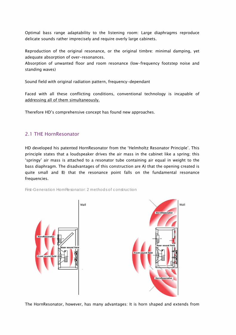
HD developed his patented HornResonator from the ‘Helmholtz Resonator Principle’. This principle states that a loudspeaker drives the air mass in the cabinet like a spring; this ‘springy’ air mass is attached to a resonator tube containing air equal in weight to the bass diaphragm. The disadvantages of this construction are A) that the opening created is quite small and B) that the resonance point falls on the fundamental resonance frequencies.
First-Generation HornResonator: 2 methods of construction
The HornResonator, however, has many advantages: It is horn shaped and extends from
the resonator tube; there is a narrowing, ‘deep bass filter’ at the horn’s small end, which becomes proportionally larger all the way to the large end.
This allows the total bass projection area in the listening room to be increased with a minimum of sound distortion. The ‘deep bass filter’ at the beginning of the resonator tube ensures the correct frequency range, preventing sound coloration caused by the horn. To prove that the air mass in the HornResonator truly functions as a diaphragm, and not just as an air funnel, one may simply hold a flame in front of it and observe how it waves in time to the music. Only actively vibrating particles can cause other media to vibrate. Furthermore the angle of the HornResonator’s form enables the production of not just one fundamental resonance tone, but of many varied resonance tones spread across the entire bass spectrum.
Finally, a natural acoustic frequency division takes place at 130 Hz. Frequencies above 130 Hz are projected by the low mid-range’s front sound field, while the bass driver’s rear sound field drives the HornResonator. 130 Hz are located in the critical fundamental tone area where it is especially important for sound to be as distortion-free as possible (see 3.2 ‘The Acoustic Active Crossover’).
Minimal bass distortion is the basis for producing natural sound. No matter how well constructed a loudspeaker is, it will fail to produce a natural sound without the HornResonator’s high precision level.
To learn more about improvements in bass range adaptability to the listening room, please refer to ‘The Horn Function’ in APPENDIX B.
2.2 THE SECOND-GENERATION HornResonator WITH Acoustic SoundBoards
The second-generation HornResonator has ushered in a new era in sound reproduction and clearly outperforms the first generation in quality as well as in bass and mid-range reproduction.
Instruments are made up of small sound stimulators (i.e. strings, mouthpieces, reeds, etc.) coupled with large resonators and projection surfaces for projecting the sound into the room. Singers make an extremely poignant example of the necessity of resonators, for only after learning how to implement their resonator through years of training, do they find their true voice.
Using musical instruments and human voices as models, our loudspeaker research and development has moved away from bass drivers with large diameters to significantly smaller and more powerful designs. Bösendorfer loudspeakers now employ powerful 130 mm bass drivers coupled with large Acoustic SoundBoards of the second-generation HornResonator.
SOUND PRODUCTION AND SOUND PROJECTION
The Acoustic SoundBoards feature a ‘double output’ function: Air floats between the cabinet and the board (see APPENDIX A). The boards function as active sound-producing diaphragms with no over-resonances. The normally passive Acoustic SoundBoards vibrate thanks to the defined distance from the cabinet. The advantage of Acoustic SoundBoards compared to ‘passive radiators’ is the increase in impulse dynamics, and thereby the decrease in after-vibrations. This effect is caused by their acousticpneumatic coupling with the bass drivers.
Acoustic SoundBoards are freely vibrating diaphragms which are capable of expanding their diameter. Their amplitude can be modified by adjusting the clamp bolts, creating an effect similar to stiffening the sound board of a Bösendorfer Grand Piano. Both the natural sound field’s projection at the original performance as well as the acoustic characteristics of the listening environment are taken into consideration by the different sound projection of the tonal ranges:
Bass tones naturally form spherical waves and are projected on a large scale by the Acoustic SoundBoards, driven by the bass driver‘s rear sound field.
With midrange tones, the spherical radiation waves of the original sound can be fully taken into account. The placement of the low mid-range drivers on both sides allows mid-range frequencies to be reproduced in spherical waveform via the front sound field. In this way the sound is formed by direct sound and reflection.
High frequency tones are club-formed, which makes direct positioning of the tweeters an absolute necessity. If broader radiation patterns were used, unwanted reflections in the listening room would lead to phase errors, since in most cases the listening room is smaller than the place of the original recording, e.g. a concert hall, an opera house or a jazz club.
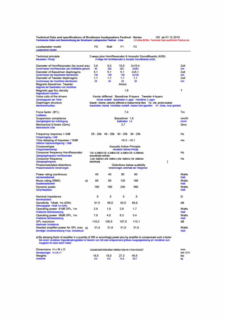
2.3 Acoustic SoundRods (developed 2010)
The new grills in front of the Midrange-Woofers by the series Festival and JB. with their rods makes still more similar the sound stage of the speakers to than of originally musical instruments. The function of ASR is that there are helping in the kind of greater membranes. Further the ASR work as acoustically lenses (Dispersion). Also they are beauty designed.
2.4 ARRANGEMENT OF THE LOW MID-RANGE SPEAKERS
In case the mid-range drivers are directed straight forwards, there will appeare too high sound boundels in the presence area. The consequences are: - too direct sound - thereby a little bit bundled hardness in the sound - coarser undifferentiated, more unsensitive sound
(Such an effect can also appear if you use LS- and NF cables which do not open the sound enough.)
However, the optimal musicality is reached by the lateral arrangement of the low mid-range drivers - also in the reproduction.
The low mid-range drivers are arranged symmetrically for each pair of loudspeakers. Even if a loudspeaker pair is placed symmetrically in the listening room, there will be differences in the distance between each driver and the surrounding walls. Acoustically, compensating for such irregularities requires an excellent distribution of resonances. The distance between the low mid-range drivers and the tweeters is precisely defined to keep phase distortion between the two systems at an absolute minimum.
3.1 OPTIMAL CABINET DAMPING
Cabinet damping is often misunderstood. Typically cabinets are literally stuffed with damping material in order to muffle resonances. Resonances, however, may easily be brought under control by other means such as intelligent cabinet structure, angled or specially-shaped walls and use of alternative materials. In this way all non-linearity in the damping can be avoided since the effectiveness of any kind of damping material decreases at lower frequencies. This creates non-linear damping relationships (a fundamental law of acoustics).
Brodmann loudspeaker cabinets contain no additional damping material; their proportions are CADCAM-designed before being acoustically and empirically optimized. In this way, the cabinet proportions themselves are a major factor in sound reproduction. The result is a sound of unbelievable lightness and airiness.
3.2 THE ACOUSTIC ACTIVE CROSSOVER
The Acoustic Active Crossover was developed by HD in 1973. Until then, acoustic pressure as a function of frequency had been the main factor in loudspeaker and crossover design. The correlation between crossover design and resulting sound was negligible. Once phasemodulated distortion was taken into account by the design, the results were striking.
In the following years, amplitude, frequency, intermodulation and pulse-modulated distortion were additionally taken into consideration. Although these individual types of distortion may be measured separately, they actually act simultaneously, multiplying their effects. Modulation distortion greatly affects sound, its emotion and its very feeling. For example, a violin’s vibrato is itself a modulation; the lower the modulation distortion is, the more convincingly it is reproduced.
Only crossovers up to the first order produce linear distortion. When higher order filters are used, pronounced positive effects are offset by non-linear distortion. This was the beginning of the Acoustic Active Crossover, where cabinet and drivers are so perfectly matched together that minimal correction using only a purist crossover filter is required. In Bösendorfer VC loudspeakers, bass drivers operate over their entire frequency range and achieve the desired frequency on their own; the tweeter is marginally corrected.
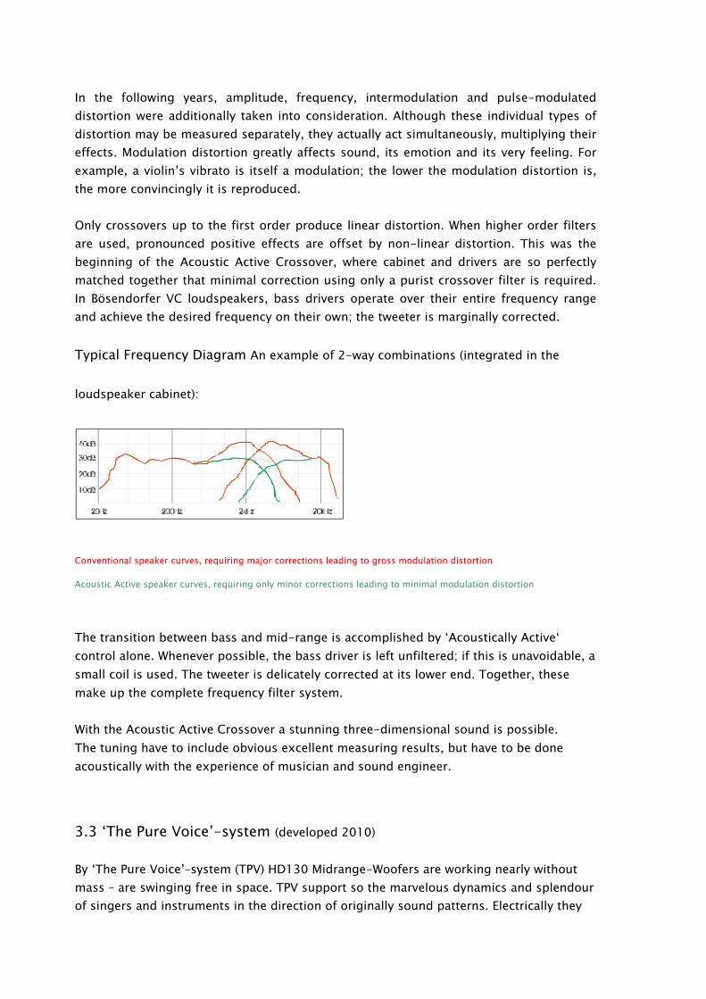
Typical Frequency Diagram An example of 2-way combinations (integrated in the
loudspeaker cabinet):
Conventional speaker curves, requiring major corrections leading to gross modulation distortion
Acoustic Active speaker curves, requiring only minor corrections leading to minimal modulation distortion
The transition between bass and mid-range is accomplished by ‘Acoustically Active‘ control alone. Whenever possible, the bass driver is left unfiltered; if this is unavoidable, a small coil is used. The tweeter is delicately corrected at its lower end. Together, these make up the complete frequency filter system.
With the Acoustic Active Crossover a stunning three-dimensional sound is possible. The tuning have to include obvious excellent measuring results, but have to be done acoustically with the experience of musician and sound engineer.
3.3 ‘The Pure Voice’-system (developed 2010) By ‘The Pure Voice’–system (TPV) HD130 Midrange-Woofers are working nearly without mass – are swinging free in space. TPV support so the marvelous dynamics and splendour of singers and instruments in the direction of originally sound patterns. Electrically they
are working in a full range manner but acoustically the effect of the acoustic short circuit lets reach a highpass filter function free of any distortions! So the system include also a phase-shifting function.
4.1 CONVENTIONAL SPEAKERS VS. BRODMANN SPEAKERS
Brodmann loudspeakers are typical two-way systems combining low and mid-range drivers and tweeters to produce as little distortion as possible. Impedance corresponds to the number of speakers used.
We use electro-dynamic speakers since these are best suited to satisfy a variety of criteria. No other system can move the air mass so homogenously through the diaphragm. Neither ion drivers, ribbons, nor electrostatic or magneto static designs can achieve such balanced results. These designs all face non-linearity in dynamics, which at lower frequencies leads to insufficient amplitude in relation to the moving surface area, causing uneven airflow.
In electro-dynamic speakers, the voice coil operates within a permanent magnetic field, converting the induced tension into mechanical vibrations. These vibrations then move through the diaphragm homogeneously and with little inertia loss, stimulating the air to vibrate.
Reproduction of the full audible spectrum The maximum audible frequency range is 20 Hz – 20 kHz (a wave-length of 16 m to 1.6 cm). Apart from hearing loss of higher frequencies in the elderly, the human ear remains capable of distinguishing fine nuances within its hearing range for quite some time.
To reproduce the full audible spectrum with as little distortion as possible, both low mid-range and high-range drivers are required. Especially at lower frequencies, implementation of the ideal diaphragm area becomes increasingly difficult. Sound waves of 16 meters would require an equivalent 16 m diaphragm diameter! As compensation, special sound guiding is necessary. The lower the frequency and the larger the wavelength, the more sound guiding will be required (and vice-versa).
Following this thesis, HD developed the HornResonator with Acoustic Sound Boards to act as an additional sound guide for lower frequencies, achieving inertia-free surface area enlargement for unhindered dynamics. The upper frequencies are of course unaffected, operating without the use of sound guides.
One of the Acoustic Active Principle’s fundamental goals is distortion minimization, as opposed to distortion correction by crossover filters, which actually produce new distortion. So we had to create speakers which, by correct dimensions and design, were capable of achieving all the desired frequencies.
Bass Drivers Magnet size, voice coil power and heaviness or lightness of diaphragm alone is of little importance for optimal loudspeakers – rather a balanced combination of these variables is the primary factor for ideal loudspeaker construction. In addition, Brodmann bass drivers are extremely powerful in order to drive the Acoustic Sound Boards.
Basket: The basket must be as rigid as possible in order to adequately complement the speaker’s kinetic energy. Steel, and not magnesium as found in many speakers, is best suited to this task. Diaphragm movement creates opposing forces corresponding to kinetic energy in proportion to amplitude. These forces must be suppressed, which requires use of rigid, sturdy baskets, featuring steel joints and correspondingly strong sound walls (bass speaker mounting surfaces). That’s why our sound walls are so massive and why we don’t use ‘flexible’ cardboard or plastic inserts between the speakers and the mounting surfaces.
Magnets: Air-gap focused magnets featuring smaller air gaps are clearly preferable to sintered ‘artificial magnets’ with their relatively large air gaps. This is because magnetic performance decreases with increasing air gap size at an exponential rate.
Voice Coil: We primarily use Kevlar voice coil mounts, a material which is rigid yet linear-damped. It’s typical of our commitment to quality that we use 6-ply voice coils featuring maximum electrical conductivity as well as custom-made, flexible voice coil connecting wires.
Diaphragm and
Suspension: The paper-maché method has proven itself to be the best for bass
diaphragms, with linear resonance characteristics and harmonious damping qualities. Our diaphragms are created like fine hand-made papers: they are soft inside, for optimal damping, and hard outside on the radiation surface, for optimal sound projection. These dual benefits are made possible by a sophisticated contactform technique – easily visible in the hard, structured diaphragm surface of the 130 mm low mid-range drivers.
Our diaphragms contain carbon fiber for high rigidity and Alaskan hemp for smoothness. The suspension isn’t made of rubber, but rather of UV-resistant Styrofoam, which is practically free of self-resonances. Plastic diaphragms are not used at all due to their non-linear resonances – just imagine a plastic violin!
Tweeters While consciously ignoring the recent fashion for metal, Brodmann was one of the first
speaker manufacturers to use silk fibers soaked in acrylic. The advantage is a diaphragm which is rigid for fast impulses and soft against unwanted resonances. The 4-ply voice coil delivers extremely fast attacks which are required to keep pace with the HornResonator’s bass tones. The slender voice coil connecting wires are reinforced and very flexible.
Both the bass drivers and the tweeters employ magnets with tiny air gaps for optimal flow. This leads to maximal conversion of energy into acoustic pressure instead of a substantial loss of energy as heat, as with conventional speakers.
4.2 OPTIMIZING CABINET FREQUENCY FOR A WELL-MODULATED SOUND
First of all the bass drivers should run at as high a frequency and the tweeters at as low a frequency as possible. In this way the ‘cut-off‘ frequencies and thereby the modulation distortion are both kept to an absolute minimum.
In practice we are confronted with certain limits: approximately 2 kHz is the ‘sound barrier’. But this isn’t feasible with conventional loudspeakers, neither with respect to frequency nor to load rating. Therefore Brodmann makes use of sophisticated diaphragm technology as well as specially-made voice coils and voice coil mounts.
5.1 FINE FINISHES ON CABINETS AND Acoustic SoundBoards
Brodmann, the manufacturer of world-famous grand pianos, treats its loudspeakers like instruments. The same premium quality is used for the cabinets, Acoustic Sound Boards, drivers and every other component.
The cabinet walls are made of high-density, specially coated wood – the same wood used for piano lids. The fine art of hand-crafted piano construction goes into their finish. The cabinet body is first sealed either in standard black or a custom color and then numerous coats of polyester-based piano varnish are applied. Finally, the surface is polished to satin finish or high-polish using a special ‘wobble’ technique. The Acoustic SoundBoards (the side-mounted diaphragms radiating sound in the lower frequencies) are available in classic black finish or in one of the finest veneers from our grand pianos – in aged Tibetan pomele, birds-eye maple, burl walnut or burl birch, for instance. The Brodmann wood specialist carefully selects each fine veneer by hand.
Veneer application is a Brodmann speciality. Only a handful of experts are proficient
at this technique. Veneer application encompasses more than precise side-by-side placement of veneer strips; the veneer’s grain creates harmonious surface ornamentation that is as natural looking as wood itself. The veneer design unites each speaker pair to create individual harmonies.
After the veneer is glued to the Brodmann Acoustic SoundBoards, the edge work begins, followed by polishing. Finally, piano varnish is applied to the veneered boards. The process is the same for the front components.
6.1 SUBJECTIVE AND OBJECTIVE HEARING
It is simply untrue that ‘everyone hears differently’. The truth is that we hear ‘digitally’ rather than ‘analog’, since from birth onwards, we have been storing acoustic signals in our ‘computer‘. We analyze these stored signals using criteria such as pitch, volume, color, pulse, etc. as well as psychological impressions such as warmth or coolness and feelings of fear or joy. All of this is accomplished by our modulation perception.
Although fingerprint and ear shape differ from person to person, our aural recognition faculty compensates for this. Otherwise it wouldn’t be possible for different people to recognize someone’s voice.
Good taste is actually objective, the prerequisites being training and a little practice. Only when errors occur do our impressions tend to be more subjective, ultimately leading to individual evaluation – what one likes or dislikes.
Therefore we can confidently claim that a good sounding loudspeaker, properly demonstrated, will please music lovers everywhere.
7.1 INSTALLATION / OPTIMIZING SOUND IN VARIOUS LISTENING ROOMS
The specialty of Brodmann’s sound is the reproduction of an instrument’s original timbre and the artist’s musical expression (true-to-life performance). This is achieved by reproducing the original resonances without the over-resonances.
Also the Acoustic SoundBoards [2,2, 2,3] obvious still do not have the dimension of music instruments with their much greater areas and even less they reach the expansion of orchestras. But just they adapt the sounds lower frequencies on the dimension of listening room, leaded without distortions [APPENDIX B, ‘horn function’]. The remaining sound lead, around the loudspeakers, will take over now from the floor area around the loudspeakers and the limit expanse of the listening room. To give right
dimension the expansion of the room part, which is leading the sound (the whole area of room limits would be much too great), by loudspeakers self is to look for the right placement. Further the result is depended on listeners position. Leaving the sweet-point in the room centre and with approach to the room wall or/and – in case of a low upper limit – almost to them (by stand up from sitting place) the part of room, which is effective as sound lead will expands (including its vibrations). The result of them is a more and more dull sound stage in direction to lower frequencies. Its coming to a maximum outside the door of listening room. Note: Music instruments, in their original dimensions, do not need support for adaptation of sound transformation to listening room and so they will not placed near to the floor or limit walls. Below described effect so here appears very much less. So the placement of your speakers in the listening environment is the most critical factor when setting them up. The more sophisticated the loudspeakers, the more sensitively will they react to the room (only inferior speakers sound the same everywhere). If the listening room is not perfect, unwanted floor and room resonances (footstep noise and standing waves) may be transmitted.
Brodmann loudspeakers do not require placement in the middle of the room; they are designed for placement near walls, as it is the most common practice.
7.2 BASIC SET-UP
Careful placement following instructions in APPENDIX B
1 Place the loudspeakers in the classic stereo triangle arrangement.2 Adjust the listener’s sitting position in the room3 Rotate the loudspeakers on their vertical (radial) axes. 4 Always watch the distance from loudspeaker sides to the wall with all models. Each
loudspeaker has bass drivers on both sides (VC 1 only has them on one side, but may be treated in the same way as the others). When positioning, take care that the distance to the nearest obstruction (wall, bookshelf, etc.) measures at least 23 cm, otherwise the sound will seem ‘tired’.
7.3 ADJUSTMENT OF LOUDSPEAKERS TO THE LISTENING ROOM
Brodmann loudspeakers and cables are designed for use in normal living rooms. Under difficult room conditions, however, the following measures may be taken to offset undesirable room effects, i.e. footstep noise or standing waves.
a Tighten the spikes as required; tightening has an audible effect and further separates the speaker from the floor. This eliminates unwanted resonances, yet can make the sound ‘thin’ if spikes are over-tightened.
b Set Diamond Plugs to muffle floor and room resonances (also see 8.1).
c Use high-quality loudspeaker cables; Brodmann provides a specially designed selection. Use type A for normal conditions and type 2 in case of excessive fundamental sound (also see 8.2).
d Separate the loudspeaker cable from the floor by using Acoustic BalanceFoam (also see 8.3).
e Improved separation of the loudspeakers from the floor by Acoustic BalanceBases (also see 8.4).
As with all fine-tuning measures, ‘more’ is not better. The correct degree of adjustment is crucial.
8.1 ACCESSORY 1: DIAMOND PLUGS
Brodmann Diamond Plugs can counter muddy, imprecise sound in the bass range caused by floor or room characteristics, especially when spike tightening and other counter-measures fail. These ‘intelligent’ resonance dampers produce effects similar to moving the loudspeakers forward in the room or tightening the spikes. If these measures are used together, their effect is compounded.
The plugs are either screwed onto the spikes from below or, for maximum effect, screwed only a few turns onto fully tightened spikes.
Warning: Under normal room conditions, excessive disconnection of the loudspeakers from the floor makes the fundamental tones ‘thinner’, depriving the sound of its original fullness. The same effect can be observed if the loudspeakers are placed too far forward in the room or if the spikes are over-tightened.
8.2 ACCESSORY 2: BRODMANN LOUDSPEAKER CABLES
Brodmann loudspeaker cables were developed in nuclear physics laboratories in the USA. They significantly augment the effects of the Acoustic Active Principle. These cables feature a number of exceptional qualities and are also used by NASA.
Key Features Single strands made of oxygen-free tempered copper pulled into a particular cross-sectional form. Each strand is encased in iridium to enable maximum conductivity, particularly on the wire surface, and to take advantage of the skin effect. Both the single strands as well as the positive and negative lines are in line with the geo-magnetic field. The cables are available in multiples of 120 cm lengths. A protective casing shields them from external influences.
The cable’s casing is made of 100% weather-proof, non-porous plastic with a transparent finish – the same cables are also used for internal loudspeaker wiring in order to optimize the signal path.
The ‘S2’ model is recommended for use with WALL and VC 1, the ‘SA’ model for use with CENTER, VC 2 and VC 7.
Our cables also feature original laboratory-quality BFA plugs, which guarantee optimal contact with the Brodmann input jacks.
Cable Placement Tips The cables should be placed with the text direction towards the loudspeakers. As with every fine instrument, cables and loudspeakers need to be broken in. We recommend playing music with natural instruments (i.e. orchestra, jazz trios, big bands or, most natural, vocalists) for a period of about 48 hours. Normal volume is sufficient. In our experience, the sound will continue to improve in the following weeks, reaching its peak performance in about one month.
8.2.1 Acoustic CableTuning-System (ACT)
With this new technology the sound of quality loudspeakers still another good step can be greatly enhanced. Introduction as technical description see under appendix B.
8.3 ACCESSORY 3: Acoustic BalanceFoam
The Acoustic BalanceFoam are foam objects of approx. 7 mm thickness and extraordinary molecular density. They are positioned under the loudspeaker cables at 10 cm intervals. Since Brodmann loudspeakers are such sensitive instruments, they will transmit all resonances, including those that are unwanted or erroneous. The unique Acoustic Balance Bases were developed to optimize loudspeaker performance in difficult rooms.
Function and Effect A loudspeaker ends not at the connectors, but at the amplifier. Loudspeaker and cable form a unit with regard to resonances. Although amplifiers are also prone to resonances, their effects on loudspeakers and cables are more dramatic because they are so closely connected to the floor and room. If tapping on the cable is clearly audible through the Acoustic SoundBoards, this means that one is hearing the feedback produced by the floor and the standing waves between floor and ceiling of the listening room.
The entire sound is influenced. Of course, normal footstep noise, such as one finds on a welldisconnected (i.e. concrete) floor, is taken into account at the tuning of our loudspeakers. However, if footstep noise or other room resonances are extreme, then the cables should be disconnected from the floor in those sections where it is required.
The results of positioning even one Acoustic BalanceFoam near the loudspeaker are clearly audible. They are a wonderful aid, but placement of too many Bases can deprive the sound of some fullness. More is not better. The correct degree of adjustment is crucial.
8.4 ACCESSORY 4: Acoustic BalanceBases
ABB (Acoustic BalanceBases) are also a tool to take away to great vibrations of rooms. This ground-base, to set under each of the loudspeakers, is formed as a sandwich of steel and
high compressed MDF material.
To use right ABB, there must be fixed even Black Diamonds on the spikes of loudspeaker bottom plate. Now should be sat under the ABB, in which almost again there are to twist spikes as well Black Diamonds. The result is similar to Black Diamonds, but much stronger in effect! It is to use at a time the room- and floor condition it makes necessary.
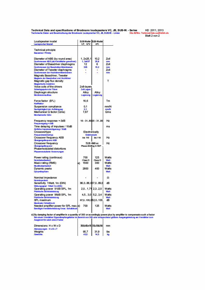
THE VERY LATEST NEW FOR 2011! - BASS/MIDRANGE ENHANCEMENT 8.5 The HD SUB-WOOFER – the most musical sub-woofer in the history of bass reproduction. “…Loudspeakers and the room together form an inseparable entity! With the HD SUB-SYSTEM one achieves previously unimagined presence and tonal richness” Hans Deutsch, Chief of Development
Sub-woofers with electronic crossovers are commonplace and used in various forms in home cinema applications. However Hans Deutsch has created a system that exhibits a whole range of decisive features and advantages. From the technical point of view this active SUB-SYSTEM is, like all Brodmann acoustics loudspeakers, a horn resonator with Acoustic Sound Boards. (Details can be found in Brodmann’s technical information under the “Acoustic Active Principle”). The DRIVER: Weight 40 pounds. The diaphragm is manufactured in a specially mixture of alloy driven by a extremely strong actuation system for leading the swinging system in a an exclusively and extraordinary precise matter. That also in cases of very great amplitudes. The Acoustic SoundBoards: On the speaker cases (with the Reference model SUB12”V 6 ½ ft. high) are docked the Acoustic SoundBoards formed like a swallow tail and working as acoustically membranes. They have been designed to be placed against the wall. The finish is of the same high standard as one has come to expect from the loudspeakers. The SUB-SYSTEM is actively driven and works brilliantly even near of corners where the flat panels attract admiring glances and at the same time provide a harmonious enhancement of the listening experience. The electronics consist of an electronic crossover and as soon as a Class D amplifier with an output of 700 Watt per Channel by an efficiency of 90%. On this basis there can be driven one till to four SUB-woofers. If four sub-woofers are required, a second separate stereo power amplifier is available. SUB12”2: How usually the electronics is integrated the speaker case. SUB12”V: The electronics were deliberately not built into the loudspeakers to avoid compromising the sound quality through someone resonance effects. System Extension With the SUB-SYSTEM creative users have several possibilities for system enhancement at their disposal which will lead to an intensification of the listening experience.
a) 1 SUB-SYSTEM is placed vertically near a corner of the room or against a wall. It can also be located horizontally, for example, under a video display.
b) 2 SUB-SYSTEMS – for example one loudspeaker in each corner is very pleasing to the eye, like two decorative columns against the wall.
c) 4 SUB-SYSTEMS and two plus two sereo-amplifiers – acoustically this version produces absolutely maximum system power! Two SUBS per side support the sound coming from the left and right of corners of the room and produce more energy than a large horn, as the special membranes (the aforementioned
Acoustic Sound Boards) cause the air in the room to vibrate in a more homogeneous manner. This version optimally satisfies the physical demands for a greater degree of adaptation to the lower frequencies (instead of the normal situation of a speaker cone working far too hard to compensate for a lack of cone area, which tends to produce a rather “nervy” bass reproduction).
PLACEMENT OF THE HD SUB-SYSTEM Placement variant “Concert” – on the wall or in room corners. The SUB loudspeakers should be placed near the corners on the wall behind your existing front loudspeakers. The basis model SUB12”2 is formed symmetrically from piece to piece and one or two pieces can be used in equipment. The reference models SUB12”V are supplied in mirror-imaged pairs to provide an excellent optical match as is the case with the option above where two SUBS are placed on the wall or near the corners as a mirror-imaged pair in such a manner that when mounted against the wall the Acoustic Sound Boards of all SUB’s face to the corners. So further more in case using four SUB’s also one pair per site. By doing this one achieves an excellent “horn-effect” and at the same time an exclusive room design. Wall Mounting Procedure: The high reference System can be fixed softly on the wall in case you think it’s necessary with a thin cord between the highest tuning screw of ASB and a planted plug in the wall. Placement variant “Home Theatre” – under the video system display. A modified placement of the SUB is recommended for some home theatre applications: here one can achieve excellent results with a SUB system mounted horizontally under the display screen with the Acoustic Sounding Boards facing upwards. The “home theatre” version is technically identical to the “concert” version. The SUB-SYSTEM is driven actively: The electronics consist of an electronic crossover (with adjustment for phase angle, frequency and volume) as soon as the Class D amplifiers, each with its 1.500 Watt music output, can drive the SUB-SYSTEMS. TECHNICAL SPECIFICATION OF THE ELECTRONICS: Frequency: 25 – 90 Hertz Phase: Continuously variable 0 - 360° Volume: 0 to +6dB
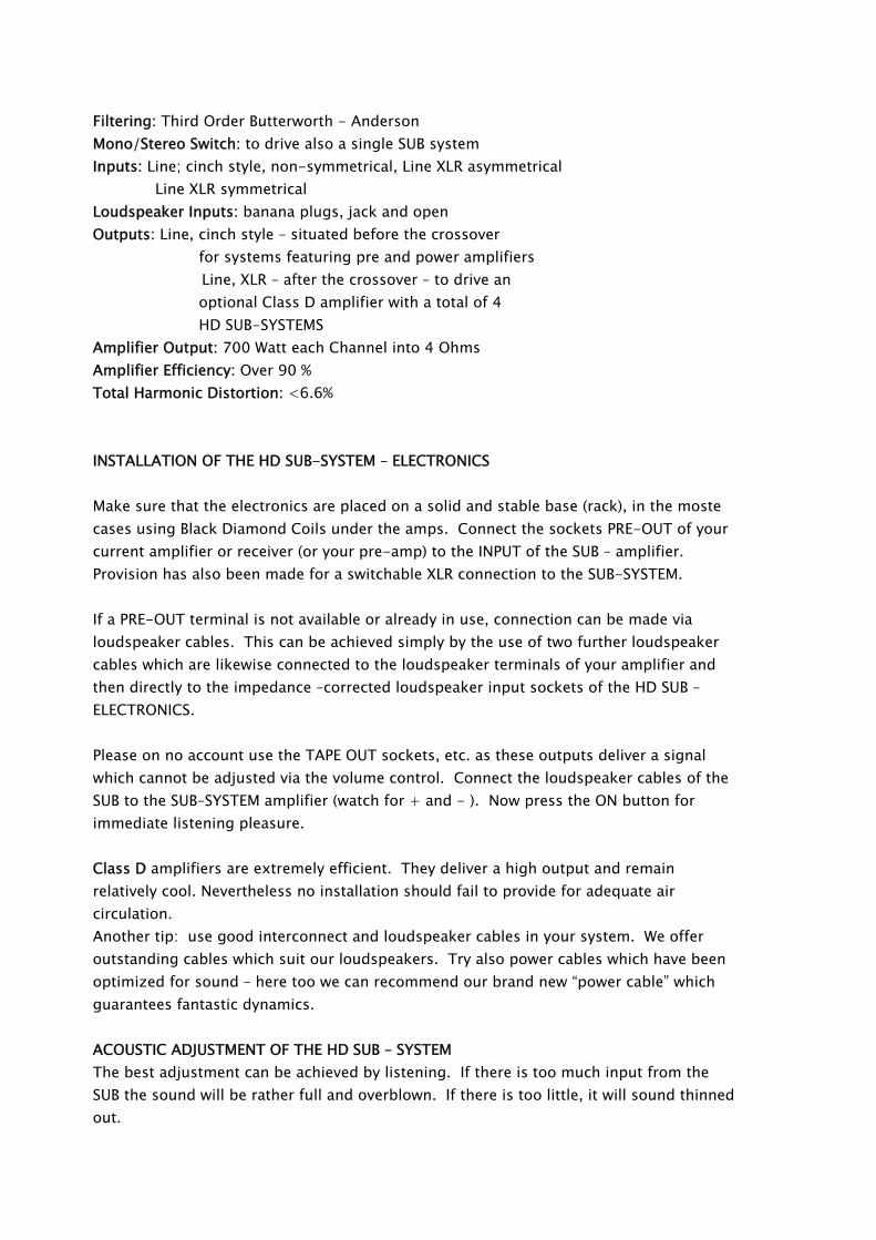
Filtering: Third Order Butterworth - Anderson Mono/Stereo Switch: to drive also a single SUB system Inputs: Line; cinch style, non-symmetrical, Line XLR asymmetrical Line XLR symmetrical Loudspeaker Inputs: banana plugs, jack and open Outputs: Line, cinch style – situated before the crossover
for systems featuring pre and power amplifiers Line, XLR – after the crossover – to drive an optional Class D amplifier with a total of 4 HD SUB-SYSTEMS
Amplifier Output: 700 Watt each Channel into 4 Ohms Amplifier Efficiency: Over 90 % Total Harmonic Distortion: <6.6% INSTALLATION OF THE HD SUB-SYSTEM – ELECTRONICS Make sure that the electronics are placed on a solid and stable base (rack), in the moste cases using Black Diamond Coils under the amps. Connect the sockets PRE-OUT of your current amplifier or receiver (or your pre-amp) to the INPUT of the SUB – amplifier. Provision has also been made for a switchable XLR connection to the SUB-SYSTEM. If a PRE-OUT terminal is not available or already in use, connection can be made via loudspeaker cables. This can be achieved simply by the use of two further loudspeaker cables which are likewise connected to the loudspeaker terminals of your amplifier and then directly to the impedance –corrected loudspeaker input sockets of the HD SUB – ELECTRONICS. Please on no account use the TAPE OUT sockets, etc. as these outputs deliver a signal which cannot be adjusted via the volume control. Connect the loudspeaker cables of the SUB to the SUB–SYSTEM amplifier (watch for + and - ). Now press the ON button for immediate listening pleasure. Class D amplifiers are extremely efficient. They deliver a high output and remain relatively cool. Nevertheless no installation should fail to provide for adequate air circulation. Another tip: use good interconnect and loudspeaker cables in your system. We offer outstanding cables which suit our loudspeakers. Try also power cables which have been optimized for sound – here too we can recommend our brand new “power cable” which guarantees fantastic dynamics. ACOUSTIC ADJUSTMENT OF THE HD SUB – SYSTEM The best adjustment can be achieved by listening. If there is too much input from the SUB the sound will be rather full and overblown. If there is too little, it will sound thinned out.
With the help of the three controls for frequency, sound level and phase angle (adjusted precisely in that order) a sound with optimum dynamics and brilliant sparkling colour can be achieved. The phase angle control is normally set at 18 degrees (looks at 8:0 a.m.) unless there is a room specific thickening of the sound which cannot be corrected by adjustment of the frequency or sound level controls or a combination of both. As a standard setting for both frequency and sound level, we recommend “1:0 a.m.” ( = 87 Hz). The sound level should take account of the local conditions and the relationship to the main electronics, basically set the control in position of “1 – 2 a.m.”. Usually the old rule is still the best: “Step on the gas until you start to notice the effect and then take your foot off a touch”. But of course it is a matter of what sort of music you want to play and the desired volume level which is needed to make a piano come to life with the correct bass resonance and a rock band to produce really solid and fundamental sound. A quote from the inventor of the HD SUB – SYSTEM, Hans Deutsch:
“As well as an overall sense of enhanced presence and sonority, the bass will exhibit greater expressiveness, dynamics and a sense of sheer “blackness”. It will take your breath away when you hear music with the SUB – SYSTEM. That I promise you.”
Hans Deutsch Worthwhile Add-ons 8.6 POWER CABLE The cable consists of artificially aged copper (25 years) which has been coated with pure silver and iridium and fitted with a high grade power plug. The secret of the cable is to be found in the combination of two construction principles which modulate each other in an absolutely fabulous way. According to the Chief of Development, Hans Deutsch, this cable endows both integrated and power amplifiers with “a warmth of sound and at the same time dynamics that resemble cannon shots”.
8.7 ARO (Acoustics RoomOptimizer)
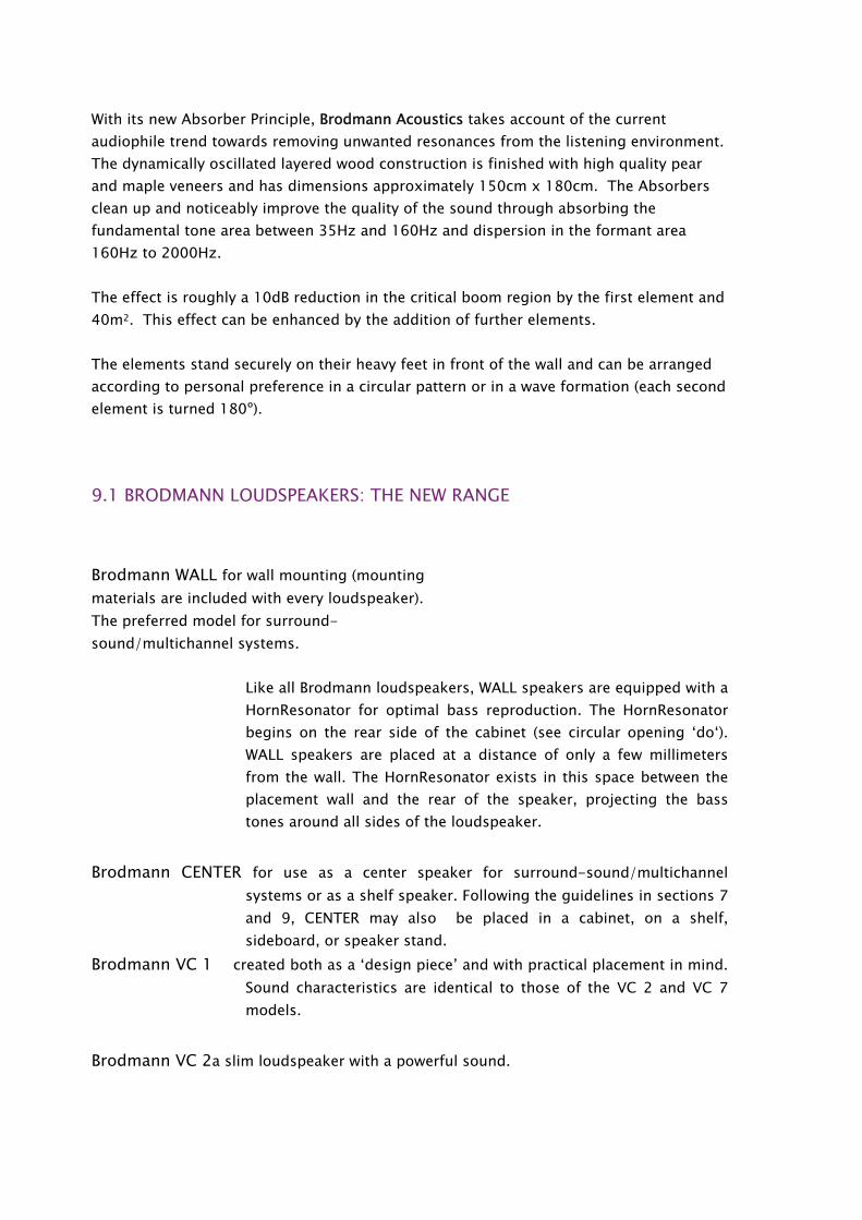
With its new Absorber Principle, Brodmann Acoustics takes account of the current audiophile trend towards removing unwanted resonances from the listening environment. The dynamically oscillated layered wood construction is finished with high quality pear and maple veneers and has dimensions approximately 150cm x 180cm. The Absorbers clean up and noticeably improve the quality of the sound through absorbing the fundamental tone area between 35Hz and 160Hz and dispersion in the formant area 160Hz to 2000Hz. The effect is roughly a 10dB reduction in the critical boom region by the first element and 40m2. This effect can be enhanced by the addition of further elements. The elements stand securely on their heavy feet in front of the wall and can be arranged according to personal preference in a circular pattern or in a wave formation (each second element is turned 180º). 9.1 BRODMANN LOUDSPEAKERS: THE NEW RANGE
Brodmann WALL for wall mounting (mounting materials are included with every loudspeaker). The preferred model for surround-sound/multichannel systems.
Like all Brodmann loudspeakers, WALL speakers are equipped with a HornResonator for optimal bass reproduction. The HornResonator begins on the rear side of the cabinet (see circular opening ‘do‘). WALL speakers are placed at a distance of only a few millimeters from the wall. The HornResonator exists in this space between the placement wall and the rear of the speaker, projecting the bass tones around all sides of the loudspeaker.
Brodmann CENTER for use as a center speaker for surround-sound/multichannel systems or as a shelf speaker. Following the guidelines in sections 7 and 9, CENTER may also be placed in a cabinet, on a shelf, sideboard, or speaker stand.
Brodmann VC 1 created both as a ‘design piece’ and with practical placement in mind. Sound characteristics are identical to those of the VC 2 and VC 7 models.
Brodmann VC 2a slim loudspeaker with a powerful sound.

Brodmann VC 7 the ultimate in concentrated dynamics as well as beauty and realism of sound. For set-up, please refer to the guidelines in sections 7 and 9. However, since these speakers are the most sensitive of all, even a few millimeters of difference in the distance to the wall will be audible, and so they will require some extra fine-tuning.
A step-by-step set-up guide with a manual is provided with every loudspeaker pair.

Our team wishes you much listening pleasure with
the BRODMANN loudspeakers!
J. Brodmann piano group GmbH Kudlichgasse 24 1100 Vienna Austria
Tel +43 (0)1 890 3203 Fax +43 (0)1 890 3203-15
Email: [email protected] Homepage: www.brodmann.com
Created out of joy for beautiful sound!

APPENDIX A: GRAPHICS AND CROSS-SECTIONS
BRODMANN VC 7- Second-Generation HornResonator
Bass tones are projected - on a large scale with excellent adaptability levels - from the two side-mounted fo-tuned Acoustic SoundBoards, which also function as passive diaphragms.
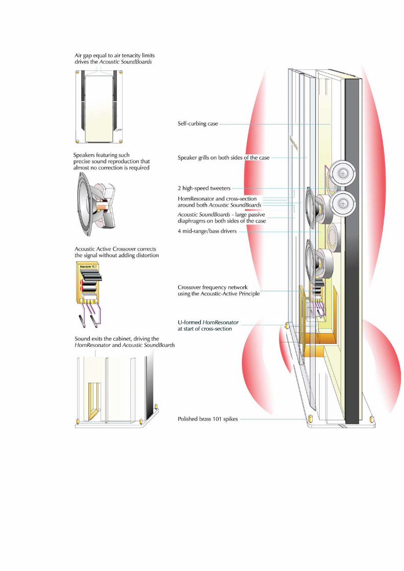
The Two Functions of the Second-Generation HornResonator
1 The resonator’s diameter (do, d//, de) determines the (distributing) fundamental resonance (fo). 2 The resonator’s circumference determines the level of adaptability to its surroundings. Of course the size of the Acoustic SoundBoards in conjunction with the air mass used (see fig. 1) causes a dramatic increase in the level of adaptability (see figs. 2-3). Furthermore the precisely defined active/passive resonation of the panels – as with Brodmann pianos – results in a significantly more ‘musical‘ sound while simultaneously damping unwanted overtones. The Acoustic SoundBoards are true diaphragms that serve to project primarily bass tones. They are the equivalent of 1500 mm in diameter, an incredible size which greatly increases the level of bass adaptability to the room.
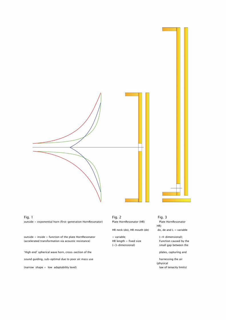
Fig. 1 Fig. 2 Fig. 3 outside = exponential horn (first-generation HornResonator) Plate HornResonator (HR) Plate HornResonator
HR)
HR neck (do), HR mouth (de) do, de and L = variable
outside + inside = function of the plate HornResonator = variable; (=4-dimensional); (accelerated transformation via acoustic resistance) HR length = fixed size Function caused by the
(=3-dimensional) small gap between the
‘High end’ spherical wave horn, cross-section of the plates, capturing and
sound guiding, sub-optimal due to poor air mass use harnessing the air (physical
(narrow shape = low adaptability level) law of tenacity limits)
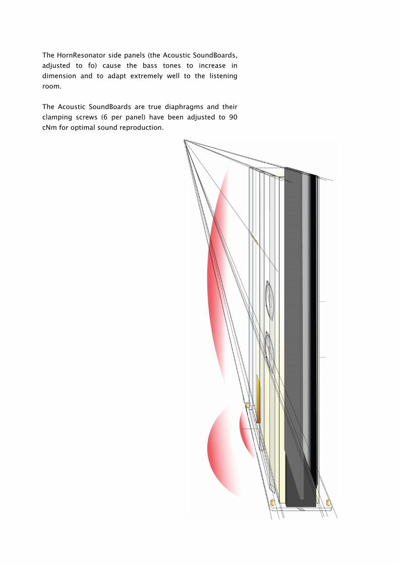
The HornResonator side panels (the Acoustic SoundBoards, adjusted to fo) cause the bass tones to increase in dimension and to adapt extremely well to the listening room.
The Acoustic SoundBoards are true diaphragms and their clamping screws (6 per panel) have been adjusted to 90 cNm for optimal sound reproduction.
APPENDIX B: TECHNICAL TEXTS
THE HORN FUNCTION
The following calculations refer to both the sound cone known as a ‘horn‘ as well as all the objects and combinations of objects to which the horn function may be applied. The horn function also defines the relationship between loudspeaker and listening room.
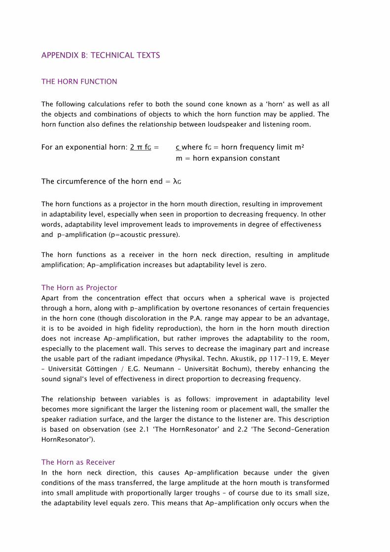
For an exponential horn: 2 π fG = c where fG = horn frequency limit m² m = horn expansion constant
The circumference of the horn end = λG
The horn functions as a projector in the horn mouth direction, resulting in improvement in adaptability level, especially when seen in proportion to decreasing frequency. In other words, adaptability level improvement leads to improvements in degree of effectiveness and p-amplification (p=acoustic pressure).
The horn functions as a receiver in the horn neck direction, resulting in amplitude amplification; Ap-amplification increases but adaptability level is zero.
The Horn as Projector Apart from the concentration effect that occurs when a spherical wave is projected through a horn, along with p-amplification by overtone resonances of certain frequencies in the horn cone (though discoloration in the P.A. range may appear to be an advantage, it is to be avoided in high fidelity reproduction), the horn in the horn mouth direction does not increase Ap-amplification, but rather improves the adaptability to the room, especially to the placement wall. This serves to decrease the imaginary part and increase the usable part of the radiant impedance (Physikal. Techn. Akustik, pp 117-119, E. Meyer – Universität Göttingen / E.G. Neumann – Universität Bochum), thereby enhancing the sound signal‘s level of effectiveness in direct proportion to decreasing frequency.
The relationship between variables is as follows: improvement in adaptability level becomes more significant the larger the listening room or placement wall, the smaller the speaker radiation surface, and the larger the distance to the listener are. This description is based on observation (see 2.1 ‘The HornResonator’ and 2.2 ‘The Second-Generation HornResonator’).
The Horn as Receiver In the horn neck direction, this causes Ap-amplification because under the given conditions of the mass transferred, the large amplitude at the horn mouth is transformed into small amplitude with proportionally larger troughs – of course due to its small size, the adaptability level equals zero. This means that Ap-amplification only occurs when the
horn neck is in direct contact with the listener (contact with the ear, for instance, when used as a hearing aid or with a recording plug when used as a substitute for a microphone).
The horn function is an absolute necessity for optimal sound reproduction. When the horn function is used in rooms smaller than fo, such as in a typical home, the loudspeaker cabinet and the room form a sound-guiding shape – a horn, in fact.
For this to occur the transition between loudspeaker and room must be perfect. A harmonious transition –accomplished by improvement in adaptability levels – becomes increasingly important at lower frequencies with their accompanying larger wavelengths.
The HornResonator and the ‘Acoustic Paravent’ (in larger rooms) form links between the loudspeakers and the room.
Try performing this simple experiment for an ‘ear-opening’ experience:
1 Music with cracking, sharp, dark-colored bass tones, from an electric bass, for example, really shows off the HornResonator’s strengths.
2 Move your ear to a position behind the loudspeaker and next to the air gap between the cabinet and one of the Acoustic Sound Boards.
3 Turn off the system and make sure it’s quiet in the room. You should still hear a low hiss, which is simply the amplified room noise.
4 Switch off or disconnect the loudspeaker you have next to your ear, and run music through the other one. You should now hear the music at a good volume though the disconnected speaker, which is obviously only amplified by the HornResonator (see above ‘The Horn as Receiver’).
The HornResonator and Acoustic SoundBoards in Brodmann loudspeakers improve adaptability in direct proportion to decreasing frequency with no errors. Minimal damping guides the sound linearly through the cabinet, while modulation distortion is minimized by ‘purist’ frequency filters and premium quality speakers.
When these methods operate together in concert, sounds are allowed to unfold in all their spectacular, natural beauty, and music is reproduced in acoustic-active fullness and precision.
SETTING UP OF BRODMANN LOUDSPEAKERS
Introduciton Brodmann loudspeaker cabinets are designed for operation in living rooms. The choice of the position in the room is essentially a practical consideration; excellent results can usually be achieved in every living room.
Floor standing cabinets are designed to be freestanding and not suitable for use on shelves. Loudspeakers and listener should form the corners of an equilateral triangle. Normally the positioning of the speaker cabinets will be parallel to, or against the wall. However under certain room conditions this need not be the case and moving the speaker cabinets at an angle to the walls will be preferable, i.e. across a corner of the room. In placing the loudspeakers against one of the shorter walls of a rectangular room, there is more of an increase in the bass than when they are placed against one of the longer walls.
The first stage is now complete. By using the short procedure described on the reverse, the sound can be improved still further. Since our ear is able to distinguish a much higher degree of complexity than, for example a computer, additional fine-tuning of the loudspeakers’ position is necessary to obtain perfect results.
The loudspeaker position in the room The closer the cabinets are positioned to the walls, the greater the increase in the bass. This effect is further increased when the speaker is positioned close to the corners. The opposite effect, a reduction in bass, occurs if the cabinets are moved away from the corners.
If the bass is increased too much the sound will lose precision, transparency, clarity and lightness. Too little bass, on the other hand, will make the fundamental sound weak, empty and thin with a possible over-presence of the mid-range and treble. In the optimum position the bass dynamic is explosive, providing full sound, clarity, transparency and lightness.
You can easily find the best position in most living rooms by conducting listening tests and moving the cabinets, making big changes to start with, and then smaller and smaller ones until you have achieved the best sound.
Changing the listener’s position Besides direct sound from the speakers, indirect sound is also reflected from the walls, ceiling and floor. Direct and indirect sound meet in the room at different angles and phases which lead to a number of peaks and troughs, mainly in the bass range frequency. So it may well be the case that by making minor changes in your sitting position there will be a noticeable change in the type of sound described under 4.2 and the effect will be heightened as required.
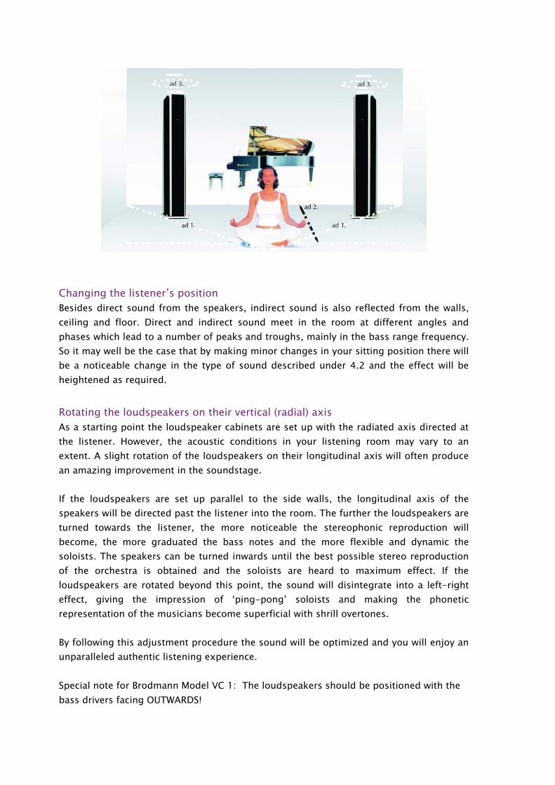
Rotating the loudspeakers on their vertical (radial) axis As a starting point the loudspeaker cabinets are set up with the radiated axis directed at the listener. However, the acoustic conditions in your listening room may vary to an extent. A slight rotation of the loudspeakers on their longitudinal axis will often produce an amazing improvement in the soundstage.
If the loudspeakers are set up parallel to the side walls, the longitudinal axis of the speakers will be directed past the listener into the room. The further the loudspeakers are turned towards the listener, the more noticeable the stereophonic reproduction will become, the more graduated the bass notes and the more flexible and dynamic the soloists. The speakers can be turned inwards until the best possible stereo reproduction of the orchestra is obtained and the soloists are heard to maximum effect. If the loudspeakers are rotated beyond this point, the sound will disintegrate into a left-right effect, giving the impression of ‘ping-pong’ soloists and making the phonetic representation of the musicians become superficial with shrill overtones.
By following this adjustment procedure the sound will be optimized and you will enjoy an unparalleled authentic listening experience.
Special note for Brodmann Model VC 1: The loudspeakers should be positioned with the bass drivers facing OUTWARDS!
ACOUSTIC CABLE TUNING
Antenna 1
Antenna 2
Shielding System
User Instructions: Pages 1-13 inclusively Schematic.
Introduction
Directions for the installation of the Acoustic CableTuning System
Technical Description
With this new technology the sound of quality loudspeakers can be greatly enhanced.
Introduction:
BRODMANN ACOUSTICS - A WORLD FIRST.
ACT – Acoustic Cable Tuning with HD Shielding.
“Loudspeakers and the room together form an indivisible whole”
(Professor Hans Deutsch, developer of the BRODMANN ACOUSTICS loudspeaker)
Every loudspeaker moves the air in the room with its drivers. The air begins to vibrate in time and
these air borne vibrations are perceived by our ears as sound. Music is in the air.
But music excites the room. All objects in the room, including the loudspeakers and the floor,
begin to vibrate. BRODMANN ACOUSTICS loudspeakers are, it would seem, the first
loudspeakers to optimize room placement and the distance from the walls by virtue of their inbuilt,
patented, “sound resonators”.
Through intensive research and insights gained from NASA space research, BRODMANN
succeeded, by exploiting the positive effects of resonances, in creating a system capable of
expanding the sound to an unprecedented level:
ACT with HD Shielding.
ACT with HD Shielding.
ACT uses the sound of loudspeakers in a room employing two sensor systems to achieve a quite
remarkable expansion of the sound.
a) Antenna 1:- registers the air borne sound;
b) Antenna 2:- registers the sound coming through the floor.
While Antenna 1 is intercepting air borne sounds by means of an ingenious passive loudspeaker
system which feeds the results to the BRODMANN ACOUSTICS loudspeakers, Antenna 2 is
registering sounds from the floor through an equally ingenious cable system situated on the floor
which likewise feeds the results to the BRODMANN ACOUSTICS loudspeakers.
c) The combination of Antenna 1 and Antenna 2 recommended by BRODMANN
ACOUSTICS achieves the most spectacular effect. Each stage - 1 or - 2 can of course be
experimented with one after the other or independently of each other.
In all cases the acoustic optimization of the Antennas is coupled with the proprietary HD Shielding
process; here false resonances present in many rooms (excessive bass, etc) are tracked down
quite precisely by both Antennas and eliminated. Only the positive, extremely precious musical
resonances remain.
What effect do Antenna 1 and Antenna 2 have on your sound system?
Both produce similar positive effects; by using the recommended combination - Antenna 1 plus
Antenna 2 - these effects are further enhanced. The sound gains in substance, fullness of
dynamics and brilliance of colour with at the same time increased precision. Above all there is a
new dimension of musical expression of feeling and emotion.
Thanks to the HD- shielding, the music takes on a hitherto never before experienced wealth of
colour and sonority. At the same time the precision of the sound is so enhanced that it produces a
fantastically clear sonic image which is, we feel, a true representation the original sound. Test
listeners noted furthermore the splendor of the finely chiseled highs and the sensuous overtones
(without any hardness), praising at the same time the speed of the bass, which depending on the
type of music, was perceived to have greater attack and to be altogether more impressive.
What does ACT entail?
ACT Equipment is just as easy to use as it is to locate unobtrusively in a room.
In the case of Antenna 1, two passive sensors (housed in a small elegant enclosure) intercept air
borne sounds and are connected via cable to the input terminals of your BRODMANN
loudspeakers.
Antenna 2 requires two floor sensors in the form of a cable to be connected to the input terminals
of your BRODMANN loudspeakers.
Included with the Shielding control unit are two special loudspeaker cables whose outer coating
passes a harmless but, from the point of view of the sound, highly effective low voltage current
which helps on the one hand to eliminate interference and on the other, to eliminate any false
resonances. The shielding control unit is easy to use and indicates by means of green, yellow,
orange and red LEDs, when the optimal balance has been achieved.
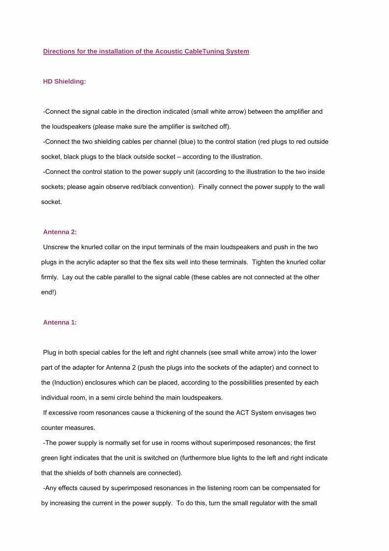
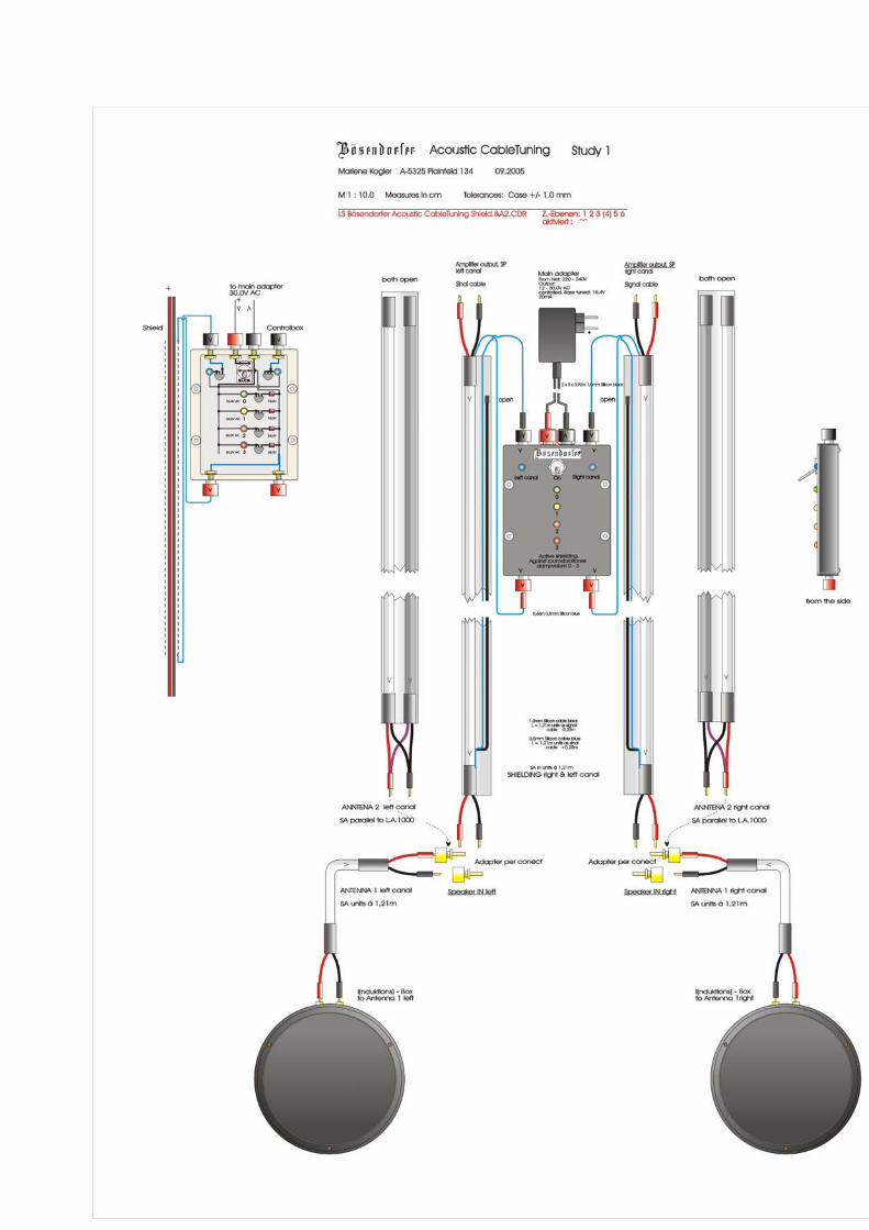
Directions for the installation of the Acoustic CableTuning System
HD Shielding:
-Connect the signal cable in the direction indicated (small white arrow) between the amplifier and
the loudspeakers (please make sure the amplifier is switched off).
-Connect the two shielding cables per channel (blue) to the control station (red plugs to red outside
socket, black plugs to the black outside socket – according to the illustration.
-Connect the control station to the power supply unit (according to the illustration to the two inside
sockets; please again observe red/black convention). Finally connect the power supply to the wall
socket.
Antenna 2:
Unscrew the knurled collar on the input terminals of the main loudspeakers and push in the two
plugs in the acrylic adapter so that the flex sits well into these terminals. Tighten the knurled collar
firmly. Lay out the cable parallel to the signal cable (these cables are not connected at the other
end!)
Antenna 1:
Plug in both special cables for the left and right channels (see small white arrow) into the lower
part of the adapter for Antenna 2 (push the plugs into the sockets of the adapter) and connect to
the (Induction) enclosures which can be placed, according to the possibilities presented by each
individual room, in a semi circle behind the main loudspeakers.
If excessive room resonances cause a thickening of the sound the ACT System envisages two
counter measures.
-The power supply is normally set for use in rooms without superimposed resonances; the first
green light indicates that the unit is switched on (furthermore blue lights to the left and right indicate
that the shields of both channels are connected).
-Any effects caused by superimposed resonances in the listening room can be compensated for
by increasing the current in the power supply. To do this, turn the small regulator with the small

screw driver provided in an anti-clockwise direction. Turn the regulator until the sound is free from
the bloated effect of the superimposed resonances. If the regulator is turned too far the sound will
become to cool. The best settings can be best determined by listening to singing (for further
information see the relevant section in the detailed description of the system).
-For checking purposes, as the current rises a yellow, then an orange and finally a red light
become illuminated on the control station.
-If the resonances in the room are very marked the three long spikes can be removed from their
holders in the Induction boxes and re-inserted bottom up like three small stilts.
Technical Description:
Fundamental observations on the role of loudspeakers, cables, etc.
-Optimal signal transfer – free from loss and distortion.
With the ACT System this transference obviously takes place in accordance with the latest
technical findings (see the Brodmann Audio Handbook “The Acoustic Active Principle”
under 8.2)
-Optimized modulation – above all phase balance.
This also occurs with the ACT System according to the latest technical findings.
-The processing of the signal from room – feedback.
The combination and working together of electronics and loudspeakers with and by means
of floor/listening room resonances such as airborne vibration.
The state of the technology has here – up until now – been based solely on the fundamental
realization that resonances have an effect on components, cables and loudspeakers alike and that
these resonances – according to received hi-fi wisdom – are damped out as much as possible
(which is often a ‘more is better type of thinking’, rather than an attempt to find the best possible
compromise). The right approach is to distinguish between the resonances that determine the
timbre (no resonance no sound) and spurious and false resonances which result from the
superimposed acoustic function of the room.
In the case of the ACT cable development under discussion sound density [ρ] is further considered
as a determining parameter [as well as sound pressure [p] sound velocity[ν], time [t] and phase[Φ]]
as functions of the frequency [λ]. These insights lead to a totally new way of thinking about the
design of cable systems. They bring about an enhancement of the sound quality never before
experienced.
Naturally the development of ACT was preceded by a knowledge of the accepted principles
concerning the interaction of room and loudspeaker. Hence the definition of the ideal home
listening room in accordance with its resonant behaviour, its reverberation time [t], that is to say its
listenability (acoustics).
[See also Handbook “The Acoustic Active Principle” under 7.1 and Appendix B ‘Listening
Function’.]
Resonant behaviour is fundamentally present in a room and in the floor when the room has not
been acoustically ‘deadened’.
The resonant behaviour thought to be pleasant in speech (t= 0.8 sec. in the lower frequencies [f],
up to 0.4 sec. in the upper frequencies), serves as a basis.
Room and loudspeakers together – acoustically – form an indivisible whole. The floor/room in the
vicinity of the loudspeaker acts as an extended signal path for the loudspeaker [See the Handbook
“The Active Acoustic Principle” at 7.1]. Its resonant behaviour and network of standing waves is
part of the total soundscape. Since BRODMANN loudspeakers reproduce optimally the timbre of
musical instruments (that is to say their resonances) the system is naturally very sensitive to
superimposed and spurious resonances emanating from the room. BRODMANN loudspeakers are
tuned for placement in ‘ideal’ rooms such as the above (for placement and tools to compensate for
non-‘ideal’ rooms, see “The Acoustic Active Principle”, at 7.1-3 and 8.1.3].
Processing the signal from room feedback
ACT builds on the above insights, but goes much further. The feedback of the sound density [ρ]
coming from oscillations (vibrations) or alternatively their density in the air as the carrier medium
with the room as the sound path (see above) represents the starting point.
Some of these effects were encountered by the author as early as the 70s in the course of his
research activities, but he was, it must be said, at that time unable to really understand what lay
behind them. So, for example, sound differences resulting from low distortion transducers
according to whether crossovers were located outside or inside the loudspeaker enclosure were
attributed at first to the change in location. According to our present knowledge the difference
accrues predominantly from the different sound densities that prevail inside and outside the
loudspeaker enclosure. In more recent times this effect could be observed in loudspeaker cables.
To compensate for a greater density inside the enclosure, cables with a somewhat understated
bass performance were chosen.
Just as – above- an inter-relationship between the loudspeaker and the room (could be
determined) (with its resonances used as an aid to location) so too could one perceive the
influence of the sound and vibrational density of the air in the room, or the sound of the
loudspeakers in the room.
Feedback
In order to use this feedback precisely as modulation for the further optimization and realistic
reproduction of the sound [true to life performance), two techniques together with a correction
device were developed.
HD – Acoustic Cable Tuning, Antenna 1 – Acoustic feedback from air vibrations
HD – Acoustic Cable Tuning, Antenna 2 – Acoustic feedback from floor vibrations
HD – Shielding (current controlled) – For the targeted and room-specific elimination of
spurious and superimposed resonances in the listening room.
The mode of operation of the two techniques of ‘Acoustic Feedback’ and ‘Acoustic Shielding’ could
hardly be more diametrically opposed. Nevertheless they work together – under quite specific
conditions - to achieve absolutely astonishing results.
HD – Acoustic Cable Tuning, Antenna 1:
Arrangement, Function and Effect: Precisely determined cables are connected to the loudspeaker
parallel to the signal bearing cable and then placed randomly (for example in a helical formation) in
the room. They are open to the amplifier but to one of the conductors a bass driver (full range) in
an enclosure is connected to serve as a conduit to the sound. These cables act as an antenna to
capture the vibrations and the sound density in the room, dependent also on the impedance of the
sound radiation. Here one can clearly discern the sound characteristics of the cables. They can
be heard together with the tuning parameters. Even the bass driver acts as an ‘antenna’, as it
becomes, as one would expect, excited by the sound radiation coming from the (signal) music
reproduction in the room. The voice coil as it moves also intensifies the antenna effect of the cable
by changing its induction value as it adjusts its position relative to the magnet.
HD – Acoustic Cable Tuning, Antenna 2:
Arrangement, Function and Effect: With this technology very special cables are laid in the room
parallel to the signal bearing cable and are connected to the loudspeakers. They are open to the
amplifier. These cables act as antennae which capture the vibrations and their density in both the
room and the floor, also dependant on the impedance of the sound radiation. Here one can again
clearly discern the sound characteristics of the cable. Again they can be heard together with the
tuning parameters.
In our extensive listening tests the best results were achieved by connecting two parallel combined
cables from the brand Synergistic Type A and EMC.
Both cables compensate for each other in that they optimize individual sound characteristics and
together produce a wonderful synergy.
The Sound:
By the application of these techniques the soundscape gains further in substance, fullness,
dynamics and brilliance of colour while nevertheless maintaining a correct balance. There is
likewise an enhanced precision in the sound (remarkable as one might expect quite the opposite
effect). Above all the sound takes on a greatness of musical expression that induces in the listener
a feeling of pure bliss.
HD Shielding – Current Controlled (to support the qualitative effect of ‘Antenna 1’ and/or
‘Antenna 2’:
Assembly, Function and Effect:
The signal bearing cable is encased in an electrically boosted shield. The shielding system should
always be used in conjunction with ‘Antenna 1’ and/or ‘Antenna 2’ – as a surveillance system. Two
blue lights indicate the function of the connected system.
Here precisely the opposite effect to that of the Antenna is achieved, namely the isolation of the
signal cable from the spurious room effects and other such effects excited by the soundfield in the
room. In spite of its diametrically opposed mode of operation to that of the Antenna
a sound quality is achieved – surprisingly – which can only be described as sensational.
Opposites attract! It must be said that we are not engaging in conventional shielding where usually
an attempt is made to deaden all sounds – the fantastic effects are achieved only at a particular
current strength (20mA and 15.4 Volts DC). The green lamp on the control box lights up when this
value is set.
Room Specific Tuning:
The above value (green light) has been determined for rooms with optimal acoustics. By using the
shielding system ACT, one can also make corrections for particular rooms. If, after the
loudspeakers have been located (see the placement instructions which accompany each
loudspeaker, as well as the Handbook “The Acoustic Active Principle” under 8.2) and ACT has
been installed and switched on, the sound is not focused and precise, further optimization can be
carried out by increasing the current (adjusting the current regulator located inside the power
supply with a small screw driver). As the current increases, first the yellow, then the orange and
finally the red indicators light up. The optimal adjustment for the room has been achieved when the
sound snaps into focus, but at the same time does not exhibit any hint of leanness and lack of
warmth in the voices and instruments. Should this effect occur, please turn back the current a little.
By use of this technology, the sound gains further in substance as described with ‘Antenna 1’ and
‘Antenna 2’. The combination of these antennas AND the precisely targeted and optimally adjusted
shielding effect induced in the signal cable, sets a totally new standard for the appreciation of the
wealth of colour and sonority of the music. At the same time in this balancing act of opposing
effects the precision of the sound is proportionally increased, so that parallel to these qualities a
fantastically clean image is achieved that simply generates a feeling of happiness. The mutual
effect of these two parameters on each other corresponds exactly to the sound achieved at the
production level in an optimal listening environment. (Normally one would expect that an increase
in sonority would lessen the precision of sound and vice versa)
In addition the highs and upper harmonics are magnificent to a degree previously unexperienced
by this author – not sibilant and heavily exaggerated, but simply intensive.
Furthermore the bass really thunders with a speed that one can only describe as having the force
of a sharp blow.
Summary:
The whole room and everything in it forms a sound transmitting, vibrating entity. Everything in the
room works in unison. (Consequently listening rooms have to be acoustically adapted to accept
loudspeakers).
The invention under discussion uses feedback from the room as a sound modulator.
Two special systems were developed which can be used separately or for greater effect in
combination. This leads to a marvelous ‘improvement’ in sound quality as was discussed under
Antenna 1 and Antenna 2. Likewise a system was developed for shielding low resistance cables
from spurious and superimposed resonances. Shielding, however, works in a way that is
diametrically opposed to that of the antenna systems developed above – a typical paradox.
The Acoustic Cable Tuning System (ACT) achieves effectiveness by virtue of its mode of
operation, together with its special materials, construction and technology so that the fundamental
working relationships between the room and the loudspeakers are considerably enhanced.
Although the opposing functions of Antenna and Shielding would seem to be self-contradictory in
the way they work, they nevertheless, given the necessary pre-requisites, complement each other.
Sound resonances are amplified via acoustic feedback (see Antenna 1 and Antenna 2) while at
the same time spurious and superimposed resonances are eliminated (Shielding).
The individual systems can be used as follows:
Antenna 1 + Shielding
Antenna 2 + Shielding - or all three parts together.
Not, however, Antenna 1 and/or Antenna 2 without Shielding!
And please do not use the Shielding system without the Antennas.
For the correct installation of the systems ‘Antenna 1’, ‘Antenna 2’ and Shielding, please consult
the enclosed schematic.
To install Antenna 1 connect the 1.21 m. cable (by means of the plug- in adaptor supplied) to the
loudspeakers parallel to the signal cable (with Shielding system attached). (The same procedure
applies to Antenna 2). To the other end of the leads attached to Antenna 1 please connect the
round (induction) woofer enclosures which can be placed discreetly behind each loudspeaker. The
spikes determine the magnitude of the effect (the closer they are to the floor the greater the effect).
Please determine the optimum distance from the floor by listening.
Hans Deutsch