Embed Size (px)
Citation preview
31020102 3
Submittal Schedule Details for VFD-P101, P201, P202, P310, P302, P401, P402
Item Tag / Equipment ID Product ID
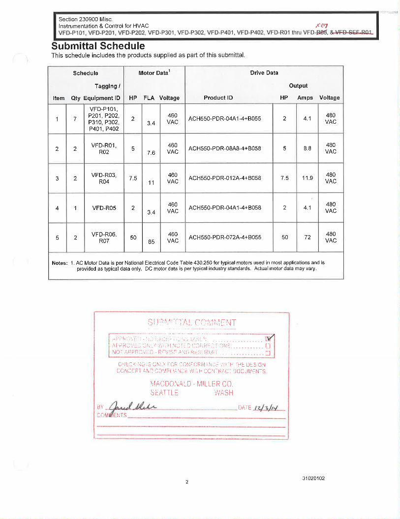
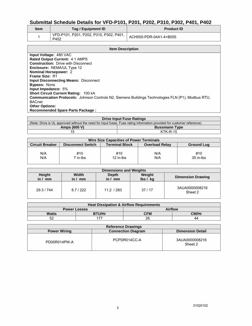
1 VFD-P101, P201, P202, P310, P302, P401, P402 ACH550-PDR-04A1-4+B055
Item Description
Input Voltage: 480 VAC Rated Output Current: 4.1 AMPS Construction: Drive with Disconnect Enclosure: NEMA/UL Type 12 Nominal Horsepower: 2 Frame Size: R1 Input Disconnecting Means: Disconnect Bypass: None Input Impedance: 5% Short Circuit Current Rating: 100 kA Communication Protocols: Johnson Controls N2, Siemens Buildings Technologies FLN (P1), Modbus RTU, BACnet Other Options: Recommended Spare Parts Package :
Drive Input Fuse Ratings (Note: Drive is UL approved without the need for input fuses. Fuse rating information provided for customer reference)
Amps (600 V) Bussmann Type
15 KTK-R-15
Wire Size Capacities of Power Terminals
Circuit Breaker Disconnect Switch Terminal Block Overload Relay Ground Lug
N/A N/A
#10 7 in-lbs
#10
12 in-lbs
N/A N/A
#10 35 in-lbs
Dimensions and Weights
Height in / mm
Width in / mm
Depth in / mm
Weight lbs / kg
Dimension Drawing
29.3 / 744 8.7 / 222 11.2 / 283 37 / 17
3AUA0000008216
Sheet 2
Heat Dissipation & Airflow Requirements
Power Losses Airflow
Watts BTU/Hr CFM CM/Hr
52 177 26 44
Reference Drawings
Power Wiring Connection Diagram Dimension Detail
PD00R014PW-A
PCPDR014CC-A
3AUA0000008216 Sheet 2

31020102 4
Submittal Schedule Details for VFD-R01, R02
Item Tag / Equipment ID Product ID
2 VFD-R01, R02 ACH550-PDR-08A8-4+B058
Item Description
Input Voltage: 480 VAC Rated Output Current: 8.8 AMPS Construction: Drive with Disconnect Enclosure: NEMA/UL Type 3R Nominal Horsepower: 5 Frame Size: R1 Input Disconnecting Means: Disconnect Bypass: None Input Impedance: 5% Short Circuit Current Rating: 100 kA Communication Protocols: Johnson Controls N2, Siemens Buildings Technologies FLN (P1), Modbus RTU, BACnet Other Options: Recommended Spare Parts Package :
Drive Input Fuse Ratings (Note: Drive is UL approved without the need for input fuses. Fuse rating information provided for customer reference)
Amps (600 V) Bussmann Type
15 KTK-R-15
Wire Size Capacities of Power Terminals
Circuit Breaker Disconnect Switch Terminal Block Overload Relay Ground Lug
N/A N/A
#10 7 in-lbs
#10
12 in-lbs
N/A N/A
#10 35 in-lbs
Dimensions and Weights
Height in / mm
Width in / mm
Depth in / mm
Weight lbs / kg
Dimension Drawing
34 / 865 17.8 / 452 13.5 / 343 128 / 58
3AUA0000016377
Sheet 1
Heat Dissipation & Airflow Requirements
Power Losses Airflow
Watts BTU/Hr CFM CM/Hr
127 433 26 44
Reference Drawings
Power Wiring Connection Diagram Dimension Detail
PD00R312PW-A
PCPDR316CC-A
3AUA0000016377 Sheet 1

31020102 5
Submittal Schedule Details for VFD-R03, R04
Item Tag / Equipment ID Product ID
3 VFD-R03, R04 ACH550-PDR-012A-4+B058
Item Description
Input Voltage: 480 VAC Rated Output Current: 11.9 AMPS Construction: Drive with Disconnect Enclosure: NEMA/UL Type 3R Nominal Horsepower: 7.5 Frame Size: R1 Input Disconnecting Means: Disconnect Bypass: None Input Impedance: 5% Short Circuit Current Rating: 100 kA Communication Protocols: Johnson Controls N2, Siemens Buildings Technologies FLN (P1), Modbus RTU, BACnet Other Options: Recommended Spare Parts Package :
Drive Input Fuse Ratings (Note: Drive is UL approved without the need for input fuses. Fuse rating information provided for customer reference)
Amps (600 V) Bussmann Type
15 KTK-R-15
Wire Size Capacities of Power Terminals
Circuit Breaker Disconnect Switch Terminal Block Overload Relay Ground Lug
N/A N/A
#10 7 in-lbs
#10
12 in-lbs
N/A N/A
#10 35 in-lbs
Dimensions and Weights
Height in / mm
Width in / mm
Depth in / mm
Weight lbs / kg
Dimension Drawing
34 / 865 17.8 / 452 13.5 / 343 128 / 58
3AUA0000016377
Sheet 1
Heat Dissipation & Airflow Requirements
Power Losses Airflow
Watts BTU/Hr CFM CM/Hr
172 587 26 44
Reference Drawings
Power Wiring Connection Diagram Dimension Detail
PD00R312PW-A
PCPDR316CC-A
3AUA0000016377 Sheet 1
31020102 6
Submittal Schedule Details for VFD-R05
Item Tag / Equipment ID Product ID
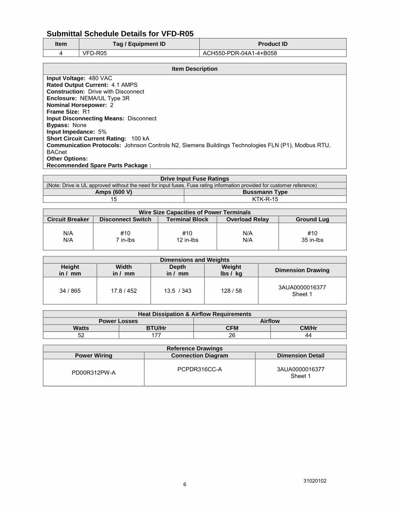
4 VFD-R05 ACH550-PDR-04A1-4+B058
Item Description
Input Voltage: 480 VAC Rated Output Current: 4.1 AMPS Construction: Drive with Disconnect Enclosure: NEMA/UL Type 3R Nominal Horsepower: 2 Frame Size: R1 Input Disconnecting Means: Disconnect Bypass: None Input Impedance: 5% Short Circuit Current Rating: 100 kA Communication Protocols: Johnson Controls N2, Siemens Buildings Technologies FLN (P1), Modbus RTU, BACnet Other Options: Recommended Spare Parts Package :
Drive Input Fuse Ratings (Note: Drive is UL approved without the need for input fuses. Fuse rating information provided for customer reference)
Amps (600 V) Bussmann Type
15 KTK-R-15
Wire Size Capacities of Power Terminals
Circuit Breaker Disconnect Switch Terminal Block Overload Relay Ground Lug
N/A N/A
#10 7 in-lbs
#10
12 in-lbs
N/A N/A
#10 35 in-lbs
Dimensions and Weights
Height in / mm
Width in / mm
Depth in / mm
Weight lbs / kg
Dimension Drawing
34 / 865 17.8 / 452 13.5 / 343 128 / 58
3AUA0000016377
Sheet 1
Heat Dissipation & Airflow Requirements
Power Losses Airflow
Watts BTU/Hr CFM CM/Hr
52 177 26 44
Reference Drawings
Power Wiring Connection Diagram Dimension Detail
PD00R312PW-A
PCPDR316CC-A
3AUA0000016377 Sheet 1

31020102 7
Submittal Schedule Details for VFD-R06, R07
Item Tag / Equipment ID Product ID
5 VFD-R06, R07 ACH550-PDR-072A-4+B055
Item Description
Input Voltage: 480 VAC Rated Output Current: 72 AMPS Construction: Drive with Disconnect Enclosure: NEMA/UL Type 12 Nominal Horsepower: 50 Frame Size: R4 Input Disconnecting Means: Disconnect Bypass: None Input Impedance: 5% Short Circuit Current Rating: 100 kA Communication Protocols: Johnson Controls N2, Siemens Buildings Technologies FLN (P1), Modbus RTU, BACnet Other Options: Recommended Spare Parts Package :
Drive Input Fuse Ratings (Note: Drive is UL approved without the need for input fuses. Fuse rating information provided for customer reference)
Amps (600 V) Bussmann Type
100 JJS-100
Wire Size Capacities of Power Terminals
Circuit Breaker Disconnect Switch Terminal Block Overload Relay Ground Lug
N/A N/A
#1 55 in-lbs
#1
48 in-lbs
N/A N/A
#1 50 in-lbs
Dimensions and Weights
Height in / mm
Width in / mm
Depth in / mm
Weight lbs / kg
Dimension Drawing
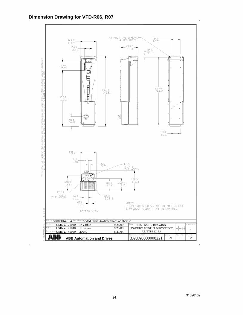
45.8 / 1163 10.5 / 267 13.1 / 332 99 / 45
3AUA0000008221
Sheet 2
Heat Dissipation & Airflow Requirements
Power Losses Airflow
Watts BTU/Hr CFM CM/Hr
1120 3820 165 280
Reference Drawings
Power Wiring Connection Diagram Dimension Detail
PD00R014PW-A
PCPDR014CC-A
3AUA0000008221 Sheet 2

31020102 8
31020102 9
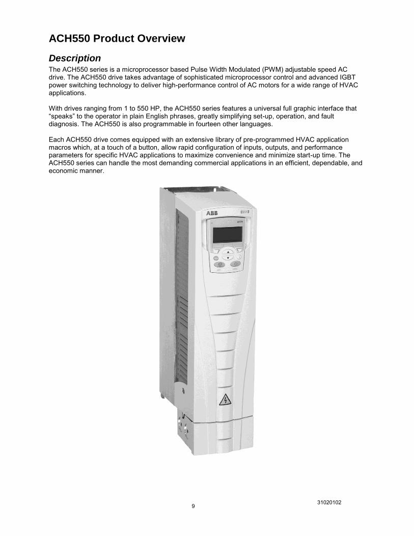
ACH550 Product Overview
Description The ACH550 series is a microprocessor based Pulse Width Modulated (PWM) adjustable speed AC drive. The ACH550 drive takes advantage of sophisticated microprocessor control and advanced IGBT power switching technology to deliver high-performance control of AC motors for a wide range of HVAC applications. With drives ranging from 1 to 550 HP, the ACH550 series features a universal full graphic interface that “speaks” to the operator in plain English phrases, greatly simplifying set-up, operation, and fault diagnosis. The ACH550 is also programmable in fourteen other languages. Each ACH550 drive comes equipped with an extensive library of pre-programmed HVAC application macros which, at a touch of a button, allow rapid configuration of inputs, outputs, and performance parameters for specific HVAC applications to maximize convenience and minimize start-up time. The ACH550 series can handle the most demanding commercial applications in an efficient, dependable, and economic manner.

31020102 10
ACH550 Standard Features UL, cUL labeled and CE marked, BTL listed EMI/RFI Filter (1st Environment, Restricted Distribution) Seismic Certificate of Compliance in accordance with IBC 2000 referencing ASCE 7-98 and ICC AC156 IBC 2003 referencing ASCE 7-02 and ICC AC156 IBC 2006 referencing ASCE 7-05 and ICC AC156 IBC 2009 referencing ASCE 7-05 and ICC AC156 Start-Up Assistants Maintenance Assistants Diagnostic Assistants Real Time Clock Includes Day, Date and Time Operator Panel Parameter Backup (read/write) Full Graphic and Multilingual Display for Operator Control, Parameter Set-Up and Operating Data Display: Output Frequency (Hz) / Motor Speed (RPM) Motor Current Calculated Energy Savings ($, kWh/MWh, CO2) Calculated % Motor Torque Calculated Motor Power (kW) DC Bus Voltage Output Voltage Heatsink Temperature Elapsed Time Meter (reset-able) KWh (reset-able) Input / Output Terminal Monitor PID Actual Value (Feedback) & Error Fault Text Warning Text Three (3) Scalable Process Variable Displays User Definable Engineering Units Two (2) Programmable Analog Inputs Six (6) Programmable Digital Inputs Two (2) Programmable Analog Outputs Up to six (6) Programmable Relay Outputs (Three (3) Standard) Adjustable Filters on Analog Inputs and Outputs Mathematical Functions on Analog Reference Signals All Control Inputs Isolated from Ground and Power Four (4) Resident Serial Communication Protocols BACnet (MS/TP) Johnson Controls N2 Siemens Building Technologies FLN (P1) Modbus RTU Input Speed Signals Current 0 (4) to 20 mA Voltage 0 (2) to 10 VDC Increase/Decrease Reference Contacts (Floating Point) Serial Communications Start/Stop 2 Wire (Dry Contact Closure) 3 Wire (Momentary Contact) Application of Input Power Application of Reference Signal (PID Sleep/Wake-Up) Serial Communications Start Functions Ramp Flying Start Pre-magnetization (DC Brake) on Start Automatic Torque Boost Automatic Torque Boost with Flying Start Auto Restart (Reset) – Customer Selectable and Adjustable Stop Functions Ramp or Coast to Stop Emergency Stop DC Braking / Hold at Stop Flux Braking Accel/Decel Two (2) sets of Independently Ramps Linear or Adjustable ‘S’ Curve Accel/Decel Ramps
HVAC Specific Application Macros Separate Safeties (2) and Run Permissive Inputs Damper Control Override Input (Fire Mode) Timer Functions Four (4) Daily Start/Stop Time Periods Four (4) Weekly Start/Stop Time Periods Four Timers for Collecting Time Periods and Overrides Seven (7) Preset Speeds Supervision Functions Adjustable Current Limit Electronic Reverse Automatic Extended Power Loss Ride Through (Selectable) Programmable Maximum Frequency to 500 Hz PID Control Two (2) Integral Independent Programmable PID Setpoint Controllers (Process and External) External Selection between Two (2) Sets of Process PID Controller Parameters PID Sleep/Wake-Up Motor Control Features Scalar (V/Hz) and Vector Modes of Motor Control V/Hz Shapes Linear Squared Energy Optimization IR Compensation Slip Compensation Three (3) Critical Frequency Lockout Bands Preprogrammed Protection Circuits Overcurrent Short Circuit Ground Fault Overvoltage Undervoltage Input Phase Loss Output Device (IGBT) Overtemperature Adjustable Current Limit Regulator UL508C approved Electronic Motor Overload (I2T) Programmable Fault Functions for Protection Include Loss of Analog Input Panel Loss External Fault Motor Thermal Protection Stall Underload Motor Phase Loss Ground Fault Input Impedance 5% Equivalent Impedance with Internal Reactor(s) Patented Swinging Choke Design for Superior Harmonic Mitigation (R1…R6 Frames) 3% Equivalent Impedance (R8 Frame) OPTIONAL FEATURES 3 Relay Extension Module (OREL-01) 115/230 V Digital input Interface Card (OHDI-01) Fieldbus Adapter Modules LonWorks BACnet IP to MS/TP Router Profibus DeviceNet Ethernet ControlNet DriveWindow Light Start-up, Operation, Programming and Diagnostic Tool Fan Replacement Kit
31020102 11
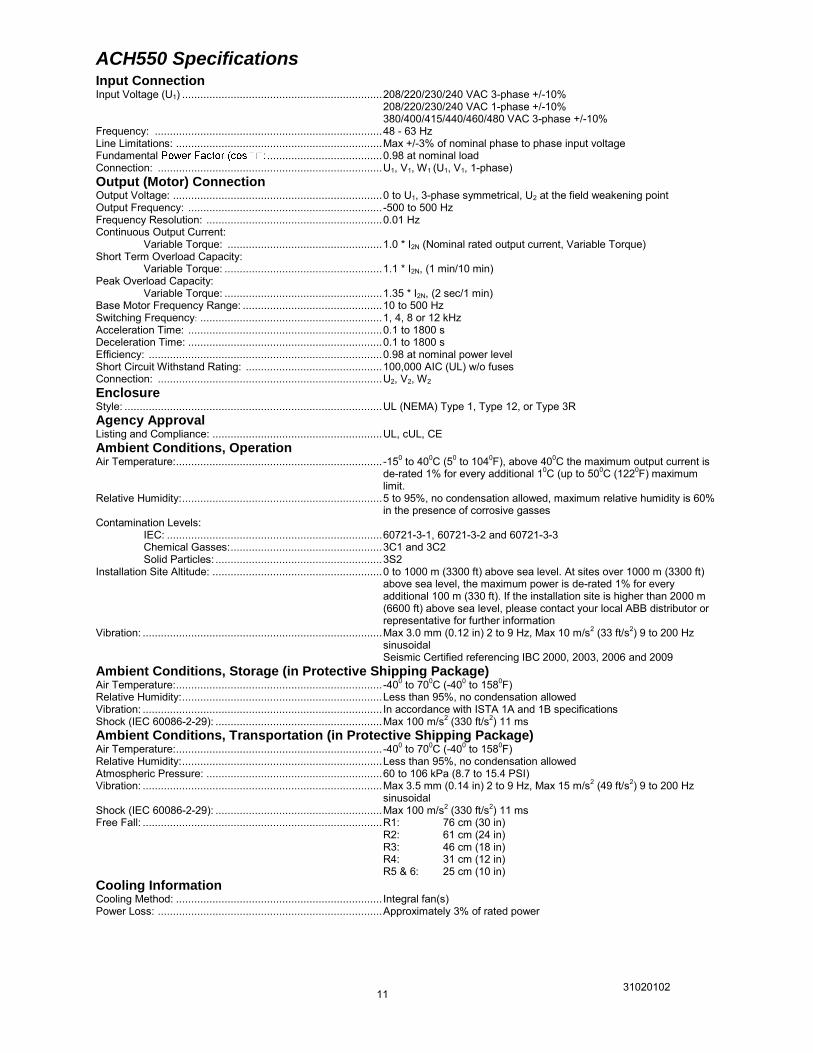
ACH550 Specifications Input Connection Input Voltage (U1) .................................................................. 208/220/230/240 VAC 3-phase +/-10% 208/220/230/240 VAC 1-phase +/-10% 380/400/415/440/460/480 VAC 3-phase +/-10% Frequency: ........................................................................... 48 - 63 Hz Line Limitations: .................................................................... Max +/-3% of nominal phase to phase input voltage Fundamental ...................................... 0.98 at nominal load Connection: .......................................................................... U1, V1, W1 (U1, V1, 1-phase) Output (Motor) Connection Output Voltage: ..................................................................... 0 to U1, 3-phase symmetrical, U2 at the field weakening point Output Frequency: ................................................................ -500 to 500 Hz Frequency Resolution: .......................................................... 0.01 Hz Continuous Output Current: Variable Torque: ................................................... 1.0 * I2N (Nominal rated output current, Variable Torque) Short Term Overload Capacity: Variable Torque: .................................................... 1.1 * I2N, (1 min/10 min) Peak Overload Capacity: Variable Torque: .................................................... 1.35 * I2N, (2 sec/1 min) Base Motor Frequency Range: .............................................. 10 to 500 Hz Switching Frequency: ............................................................ 1, 4, 8 or 12 kHz Acceleration Time: ................................................................ 0.1 to 1800 s Deceleration Time: ................................................................ 0.1 to 1800 s Efficiency: ............................................................................. 0.98 at nominal power level Short Circuit Withstand Rating: ............................................. 100,000 AIC (UL) w/o fuses Connection: .......................................................................... U2, V2, W2 Enclosure Style: ..................................................................................... UL (NEMA) Type 1, Type 12, or Type 3R Agency Approval Listing and Compliance: ........................................................ UL, cUL, CE Ambient Conditions, Operation Air Temperature: .................................................................... -150 to 400C (50 to 1040F), above 400C the maximum output current is
de-rated 1% for every additional 10C (up to 500C (1220F) maximum limit.
Relative Humidity: .................................................................. 5 to 95%, no condensation allowed, maximum relative humidity is 60% in the presence of corrosive gasses
Contamination Levels: IEC: ....................................................................... 60721-3-1, 60721-3-2 and 60721-3-3 Chemical Gasses: .................................................. 3C1 and 3C2 Solid Particles: ....................................................... 3S2 Installation Site Altitude: ........................................................ 0 to 1000 m (3300 ft) above sea level. At sites over 1000 m (3300 ft)
above sea level, the maximum power is de-rated 1% for every additional 100 m (330 ft). If the installation site is higher than 2000 m (6600 ft) above sea level, please contact your local ABB distributor or representative for further information
Vibration: ............................................................................... Max 3.0 mm (0.12 in) 2 to 9 Hz, Max 10 m/s2 (33 ft/s2) 9 to 200 Hz sinusoidal Seismic Certified referencing IBC 2000, 2003, 2006 and 2009
Ambient Conditions, Storage (in Protective Shipping Package) Air Temperature: .................................................................... -400 to 700C (-400 to 1580F) Relative Humidity: .................................................................. Less than 95%, no condensation allowed Vibration: ............................................................................... In accordance with ISTA 1A and 1B specifications Shock (IEC 60086-2-29): ....................................................... Max 100 m/s2 (330 ft/s2) 11 ms Ambient Conditions, Transportation (in Protective Shipping Package) Air Temperature: .................................................................... -400 to 700C (-400 to 1580F) Relative Humidity: .................................................................. Less than 95%, no condensation allowed Atmospheric Pressure: .......................................................... 60 to 106 kPa (8.7 to 15.4 PSI) Vibration: ............................................................................... Max 3.5 mm (0.14 in) 2 to 9 Hz, Max 15 m/s2 (49 ft/s2) 9 to 200 Hz
sinusoidal Shock (IEC 60086-2-29): ....................................................... Max 100 m/s2 (330 ft/s2) 11 ms Free Fall: ............................................................................... R1: 76 cm (30 in) R2: 61 cm (24 in) R3: 46 cm (18 in) R4: 31 cm (12 in) R5 & 6: 25 cm (10 in) Cooling Information Cooling Method: .................................................................... Integral fan(s) Power Loss: .......................................................................... Approximately 3% of rated power
31020102 12
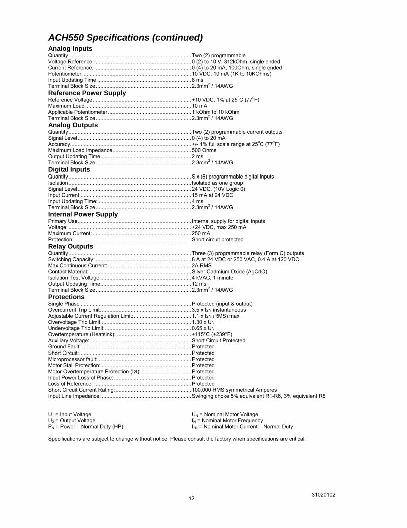
ACH550 Specifications (continued) Analog Inputs Quantity ................................................................................. Two (2) programmable Voltage Reference: ................................................................ 0 (2) to 10 V, 312kOhm, single ended Current Reference: ................................................................ 0 (4) to 20 mA, 100Ohm, single ended Potentiometer: ....................................................................... 10 VDC, 10 mA (1K to 10KOhms) Input Updating Time .............................................................. 8 ms Terminal Block Size ............................................................... 2.3mm2 / 14AWG Reference Power Supply Reference Voltage ................................................................. +10 VDC, 1% at 250C (770F) Maximum Load ...................................................................... 10 mA Applicable Potentiometer ....................................................... 1 kOhm to 10 kOhm Terminal Block Size ............................................................... 2.3mm2 / 14AWG Analog Outputs Quantity ................................................................................. Two (2) programmable current outputs Signal Level ........................................................................... 0 (4) to 20 mA Accuracy................................................................................ +/- 1% full scale range at 250C (770F) Maximum Load Impedance .................................................... 500 Ohms Output Updating Time ............................................................ 2 ms Terminal Block Size ............................................................... 2.3mm2 / 14AWG Digital Inputs Quantity ................................................................................. Six (6) programmable digital inputs Isolation ................................................................................. Isolated as one group Signal Level ........................................................................... 24 VDC, (10V Logic 0) Input Current ......................................................................... 15 mA at 24 VDC Input Updating Time: ............................................................. 4 ms Terminal Block Size ............................................................... 2.3mm2 / 14AWG Internal Power Supply Primary Use ........................................................................... Internal supply for digital inputs Voltage: ................................................................................. +24 VDC, max 250 mA Maximum Current: ................................................................. 250 mA Protection: ............................................................................. Short circuit protected Relay Outputs Quantity ................................................................................. Three (3) programmable relay (Form C) outputs Switching Capacity: ............................................................... 8 A at 24 VDC or 250 VAC, 0.4 A at 120 VDC Max Continuous Current: ....................................................... 2A RMS Contact Material: ................................................................... Silver Cadmium Oxide (AgCdO) Isolation Test Voltage ............................................................ 4 kVAC, 1 minute Output Updating Time ............................................................ 12 ms Terminal Block Size ............................................................... 2.3mm2 / 14AWG Protections Single Phase ......................................................................... Protected (input & output) Overcurrent Trip Limit: ........................................................... 3.5 x I2N instantaneous Adjustable Current Regulation Limit: ...................................... 1.1 x I2N (RMS) max. Overvoltage Trip Limit: ........................................................... 1.30 x UN Undervoltage Trip Limit: ......................................................... 0.65 x UN Overtemperature (Heatsink): ................................................. +115°C (+239°F) Auxiliary Voltage: ................................................................... Short Circuit Protected Ground Fault: ........................................................................ Protected Short Circuit: .......................................................................... Protected Microprocessor fault: ............................................................. Protected Motor Stall Protection: ........................................................... Protected Motor Overtemperature Protection (I2t): ................................. Protected Input Power Loss of Phase: ................................................... Protected Loss of Reference: ................................................................ Protected Short Circuit Current Rating: .................................................. 100,000 RMS symmetrical Amperes Input Line Impedance: ........................................................... Swinging choke 5% equivalent R1-R6, 3% equivalent R8 U1 = Input Voltage UN = Nominal Motor Voltage U2 = Output Voltage fN = Nominal Motor Frequency PN = Power – Normal Duty (HP) I2N = Nominal Motor Current – Normal Duty Specifications are subject to change without notice. Please consult the factory when specifications are critical.
31020102 13
ACH550 Control Panel
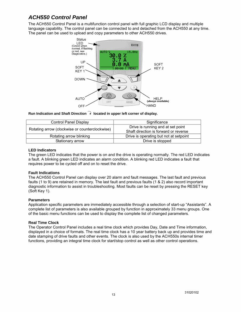
The ACH550 Control Panel is a multifunction control panel with full graphic LCD display and multiple language capability. The control panel can be connected to and detached from the ACH550 at any time. The panel can be used to upload and copy parameters to other ACH550 drives.
Run Indication and Shaft Direction located in upper left corner of display.
Control Panel Display Significance
Rotating arrow (clockwise or counterclockwise) Drive is running and at set point Shaft direction is forward or reverse
Rotating arrow blinking Drive is operating but not at setpoint Stationary arrow Drive is stopped
LED Indicators The green LED indicates that the power is on and the drive is operating normally. The red LED indicates a fault. A blinking green LED indicates an alarm condition. A blinking red LED indicates a fault that requires power to be cycled off and on to reset the drive. Fault Indications The ACH550 Control Panel can display over 20 alarm and fault messages. The last fault and previous faults (1 to 9) are retained in memory. The last fault and previous faults (1 & 2) also record important diagnostic information to assist in troubleshooting. Most faults can be reset by pressing the RESET key (Soft Key 1). Parameters Application specific parameters are immediately accessible through a selection of start-up “Assistants”. A complete list of parameters is also available grouped by function in approximately 33 menu groups. One of the basic menu functions can be used to display the complete list of changed parameters. Real Time Clock The Operator Control Panel includes a real time clock which provides Day, Date and Time information, displayed in a choice of formats. The real time clock has a 10 year battery back up and provides time and date stamping of drive faults and other events. The clock is also used by the ACH550s internal timer functions, providing an integral time clock for start/stop control as well as other control operations.
31020102 14
Control Modes When the HAND key is pressed, the drive starts and pressing the UP/DOWN keys can modify the reference frequency. The HAND (keypad) control mode is indicated. When the OFF key is pressed, the drive stops and the OFF control mode is indicated. When the AUTO key is pressed, the AUTO control mode is indicated. The drive can be started and stopped using whichever remote start/stop command has been configured, a contact closure applied to the start/stop input, a serial communication command or a process feedback signal. In AUTO mode the drive speed is typically controlled by the external speed reference input or by the PID controller. If the HAND key is pressed while the drive is running in the AUTO control mode, the drive continues to run without changing speed, but ceases to respond to external input or PID speed reference changes. (Bumpless transfer) Pressing the UP/DOWN keys can modify the reference frequency. If the AUTO key is pressed while the drive is running in the HAND control mode and an external start command is present, the drive continues to run and follows the acceleration or deceleration control ramp to the speed set by the external input or PID speed reference. (Bumpless transfer)
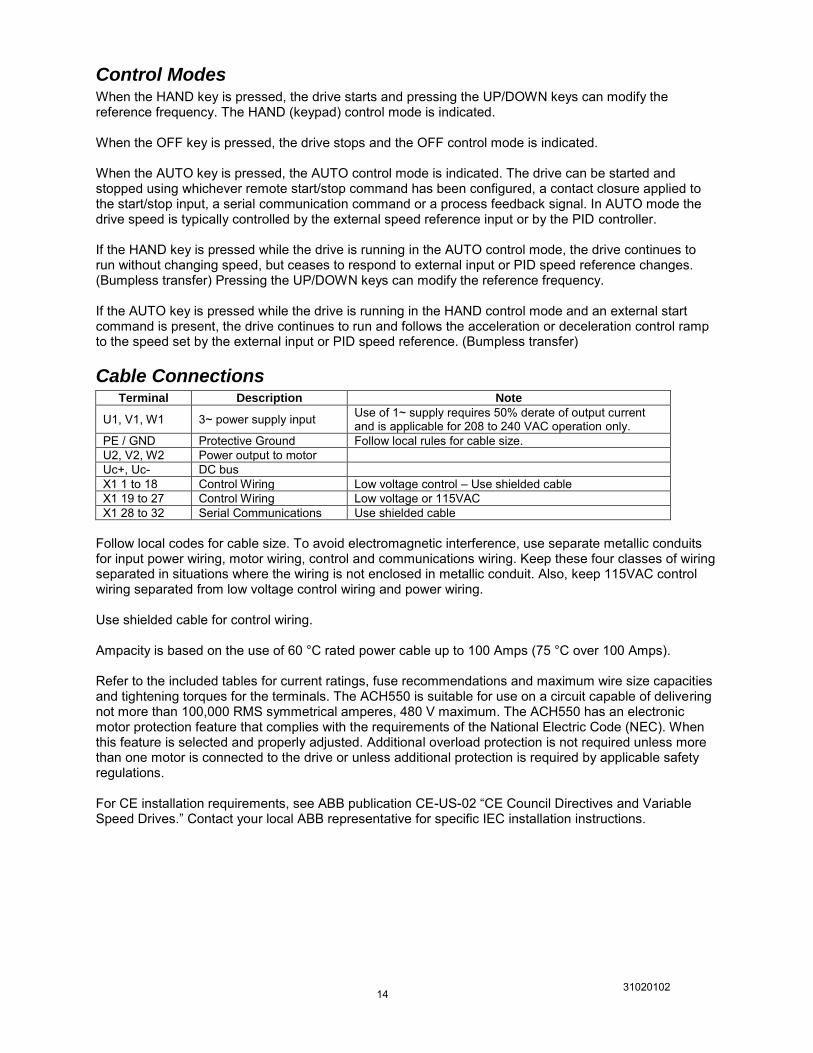
Cable Connections Terminal Description Note
U1, V1, W1 3~ power supply input Use of 1~ supply requires 50% derate of output current and is applicable for 208 to 240 VAC operation only.
PE / GND Protective Ground Follow local rules for cable size. U2, V2, W2 Power output to motor Uc+, Uc- DC bus X1 1 to 18 Control Wiring Low voltage control – Use shielded cable X1 19 to 27 Control Wiring Low voltage or 115VAC X1 28 to 32 Serial Communications Use shielded cable
Follow local codes for cable size. To avoid electromagnetic interference, use separate metallic conduits for input power wiring, motor wiring, control and communications wiring. Keep these four classes of wiring separated in situations where the wiring is not enclosed in metallic conduit. Also, keep 115VAC control wiring separated from low voltage control wiring and power wiring. Use shielded cable for control wiring. Ampacity is based on the use of 60 °C rated power cable up to 100 Amps (75 °C over 100 Amps). Refer to the included tables for current ratings, fuse recommendations and maximum wire size capacities and tightening torques for the terminals. The ACH550 is suitable for use on a circuit capable of delivering not more than 100,000 RMS symmetrical amperes, 480 V maximum. The ACH550 has an electronic motor protection feature that complies with the requirements of the National Electric Code (NEC). When this feature is selected and properly adjusted. Additional overload protection is not required unless more than one motor is connected to the drive or unless additional protection is required by applicable safety regulations. For CE installation requirements, see ABB publication CE-US-02 “CE Council Directives and Variable Speed Drives.” Contact your local ABB representative for specific IEC installation instructions.
31020102 15
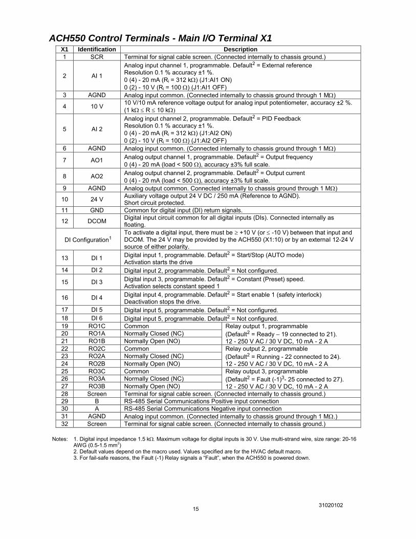
ACH550 Control Terminals - Main I/O Terminal X1 X1 Identification Description
1 SCR Terminal for signal cable screen. (Connected internally to chassis ground.)
2 AI 1
Analog input channel 1, programmable. Default2 = External reference Resolution 0.1 % accuracy ±1 %. 0 (4) - 20 mA (Ri = 312 k) (J1:AI1 ON) 0 (2) - 10 V (Ri = 100 ) (J1:AI1 OFF)
3 AGND Analog input common. (Connected internally to chassis ground through 1 M)
4 10 V 10 V/10 mA reference voltage output for analog input potentiometer, accuracy ±2 %. (1 k R 10 k
5 AI 2
Analog input channel 2, programmable. Default2 = PID Feedback Resolution 0.1 % accuracy ±1 %. 0 (4) - 20 mA (Ri = 312 k) (J1:AI2 ON) 0 (2) - 10 V (Ri = 100 ) (J1:AI2 OFF)
6 AGND Analog input common. (Connected internally to chassis ground through 1 M)
7 AO1 Analog output channel 1, programmable. Default2 = Output frequency 0 (4) - 20 mA (load < 500 ), accuracy ±3% full scale.
8 AO2 Analog output channel 2, programmable. Default2 = Output current 0 (4) - 20 mA (load < 500 ), accuracy ±3% full scale.
9 AGND Analog output common. Connected internally to chassis ground through 1 M)
10 24 V Auxiliary voltage output 24 V DC / 250 mA (Reference to AGND). Short circuit protected.
11 GND Common for digital input (DI) return signals.
12 DCOM Digital input circuit common for all digital inputs (DIs). Connected internally as floating.
DI Configuration1 To activate a digital input, there must be +10 V (or -10 V) between that input and DCOM. The 24 V may be provided by the ACH550 (X1:10) or by an external 12-24 V source of either polarity.
13 DI 1 Digital input 1, programmable. Default2 = Start/Stop (AUTO mode) Activation starts the drive
14 DI 2 Digital input 2, programmable. Default2 = Not configured.
15 DI 3 Digital input 3, programmable. Default2 = Constant (Preset) speed. Activation selects constant speed 1
16 DI 4 Digital input 4, programmable. Default2 = Start enable 1 (safety interlock) Deactivation stops the drive.
17 DI 5 Digital input 5, programmable. Default2 = Not configured. 18 DI 6 Digital input 5, programmable. Default2 = Not configured. 19 RO1C Common Relay output 1, programmable
(Default2 = Ready – 19 connected to 21). 12 - 250 V AC / 30 V DC, 10 mA - 2 A
20 RO1A Normally Closed (NC) 21 RO1B Normally Open (NO) 22 RO2C Common Relay output 2, programmable
(Default2 = Running - 22 connected to 24). 12 - 250 V AC / 30 V DC, 10 mA - 2 A
23 RO2A Normally Closed (NC) 24 RO2B Normally Open (NO) 25 RO3C Common Relay output 3, programmable
(Default2 = Fault (-1)3- 25 connected to 27). 12 - 250 V AC / 30 V DC, 10 mA - 2 A
26 RO3A Normally Closed (NC) 27 RO3B Normally Open (NO) 28 Screen Terminal for signal cable screen. (Connected internally to chassis ground.) 29 B RS-485 Serial Communications Positive input connection 30 A RS-485 Serial Communications Negative input connection 31 AGND Analog input common. (Connected internally to chassis ground through 1 M.) 32 Screen Terminal for signal cable screen. (Connected internally to chassis ground.)
Notes: 1. Digital input impedance 1.5 k Maximum voltage for digital inputs is 30 V. Use multi-strand wire, size range: 20-16
AWG (0.5-1.5 mm2) 2. Default values depend on the macro used. Values specified are for the HVAC default macro.
3. For fail-safe reasons, the Fault (-1) Relay signals a “Fault”, when the ACH550 is powered down.
31020102 16
Drive Pack Standard Features
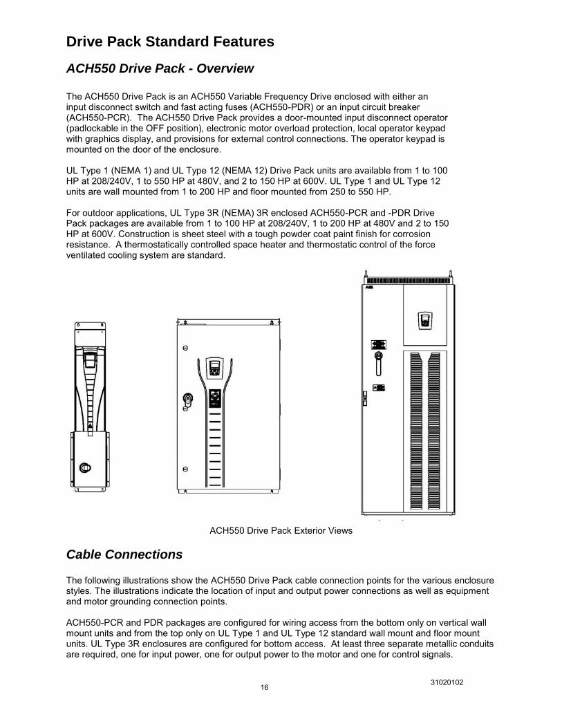
ACH550 Drive Pack - Overview
The ACH550 Drive Pack is an ACH550 Variable Frequency Drive enclosed with either an input disconnect switch and fast acting fuses (ACH550-PDR) or an input circuit breaker (ACH550-PCR). The ACH550 Drive Pack provides a door-mounted input disconnect operator (padlockable in the OFF position), electronic motor overload protection, local operator keypad with graphics display, and provisions for external control connections. The operator keypad is mounted on the door of the enclosure. UL Type 1 (NEMA 1) and UL Type 12 (NEMA 12) Drive Pack units are available from 1 to 100 HP at 208/240V, 1 to 550 HP at 480V, and 2 to 150 HP at 600V. UL Type 1 and UL Type 12 units are wall mounted from 1 to 200 HP and floor mounted from 250 to 550 HP. For outdoor applications, UL Type 3R (NEMA) 3R enclosed ACH550-PCR and -PDR Drive Pack packages are available from 1 to 100 HP at 208/240V, 1 to 200 HP at 480V and 2 to 150 HP at 600V. Construction is sheet steel with a tough powder coat paint finish for corrosion resistance. A thermostatically controlled space heater and thermostatic control of the force ventilated cooling system are standard.
ACH550 Drive Pack Exterior Views
Cable Connections The following illustrations show the ACH550 Drive Pack cable connection points for the various enclosure styles. The illustrations indicate the location of input and output power connections as well as equipment and motor grounding connection points. ACH550-PCR and PDR packages are configured for wiring access from the bottom only on vertical wall mount units and from the top only on UL Type 1 and UL Type 12 standard wall mount and floor mount units. UL Type 3R enclosures are configured for bottom access. At least three separate metallic conduits are required, one for input power, one for output power to the motor and one for control signals.
31020102 17
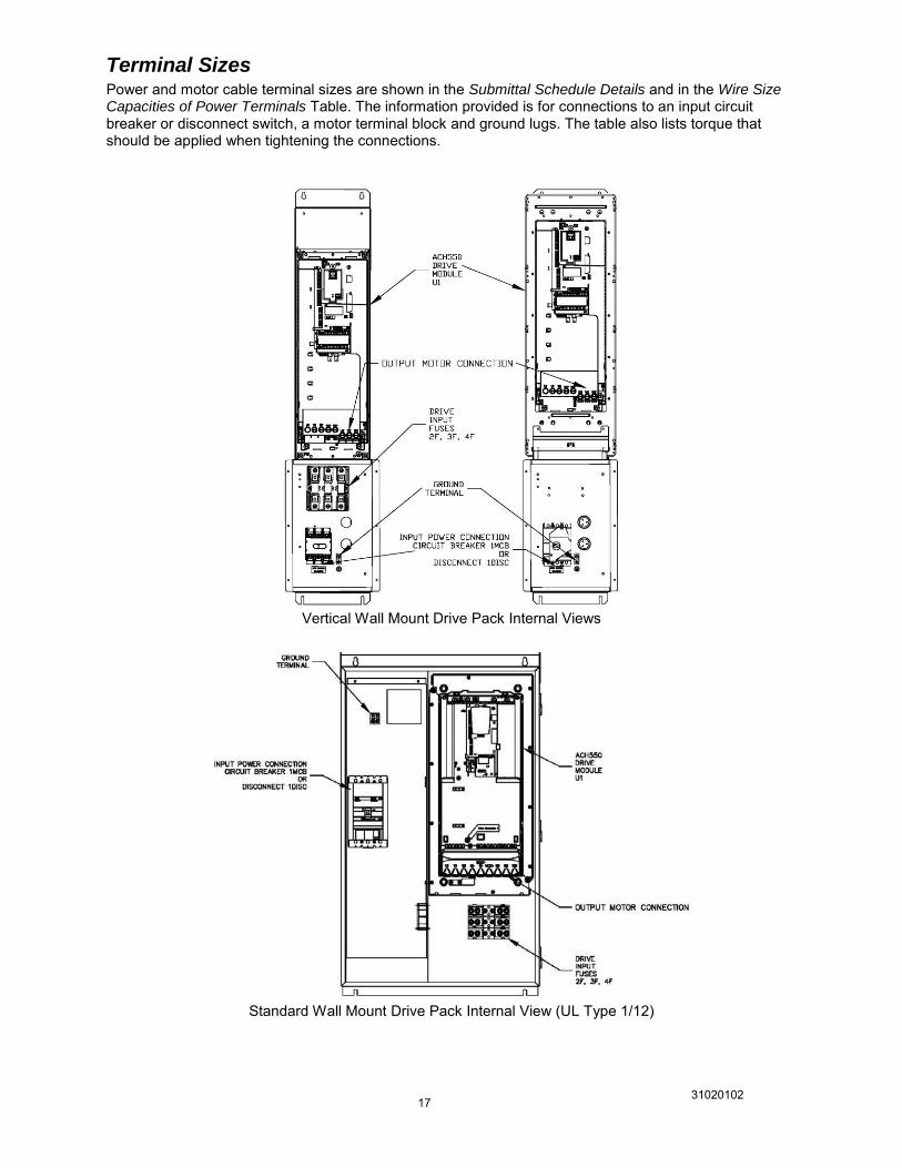
Terminal Sizes Power and motor cable terminal sizes are shown in the Submittal Schedule Details and in the Wire Size Capacities of Power Terminals Table. The information provided is for connections to an input circuit breaker or disconnect switch, a motor terminal block and ground lugs. The table also lists torque that should be applied when tightening the connections.
Vertical Wall Mount Drive Pack Internal Views
Standard Wall Mount Drive Pack Internal View (UL Type 1/12)
31020102 18
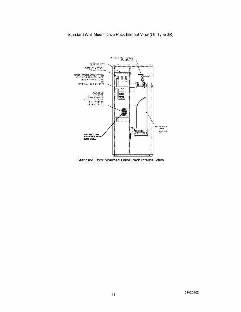
Standard Wall Mount Drive Pack Internal View (UL Type 3R)
Standard Floor Mounted Drive Pack Internal View

31020102 19
31020102 20
Engineering Data and Ratings Tables
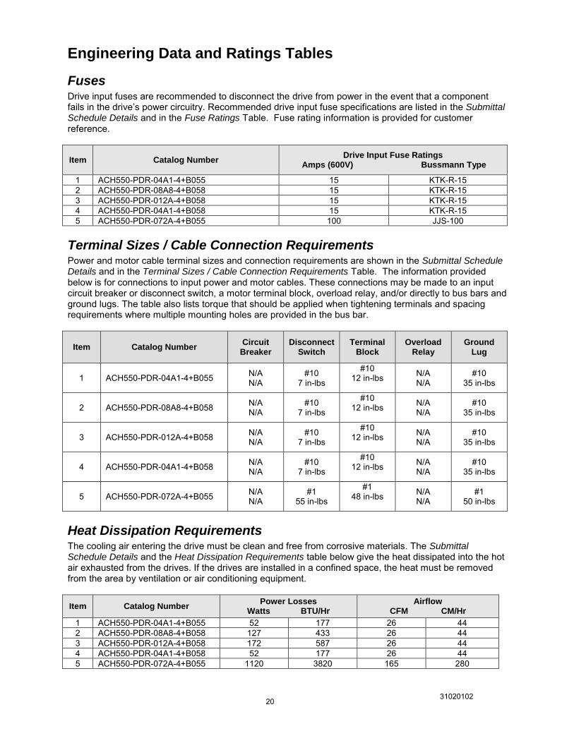
Fuses Drive input fuses are recommended to disconnect the drive from power in the event that a component fails in the drive’s power circuitry. Recommended drive input fuse specifications are listed in the Submittal Schedule Details and in the Fuse Ratings Table. Fuse rating information is provided for customer reference.
Item Catalog Number Drive Input Fuse Ratings
Amps (600V) Bussmann Type
1 ACH550-PDR-04A1-4+B055 15 KTK-R-15 2 ACH550-PDR-08A8-4+B058 15 KTK-R-15 3 ACH550-PDR-012A-4+B058 15 KTK-R-15 4 ACH550-PDR-04A1-4+B058 15 KTK-R-15 5 ACH550-PDR-072A-4+B055 100 JJS-100
Terminal Sizes / Cable Connection Requirements Power and motor cable terminal sizes and connection requirements are shown in the Submittal Schedule Details and in the Terminal Sizes / Cable Connection Requirements Table. The information provided below is for connections to input power and motor cables. These connections may be made to an input circuit breaker or disconnect switch, a motor terminal block, overload relay, and/or directly to bus bars and ground lugs. The table also lists torque that should be applied when tightening terminals and spacing requirements where multiple mounting holes are provided in the bus bar.
Item Catalog Number Circuit
Breaker Disconnect
Switch Terminal
Block Overload
Relay Ground
Lug
1 ACH550-PDR-04A1-4+B055 N/A N/A
#10 7 in-lbs
#10 12 in-lbs
N/A N/A
#10 35 in-lbs
2 ACH550-PDR-08A8-4+B058 N/A N/A
#10 7 in-lbs
#10 12 in-lbs
N/A N/A
#10 35 in-lbs
3 ACH550-PDR-012A-4+B058 N/A N/A
#10 7 in-lbs
#10 12 in-lbs
N/A N/A
#10 35 in-lbs
4 ACH550-PDR-04A1-4+B058 N/A N/A
#10 7 in-lbs
#10 12 in-lbs
N/A N/A
#10 35 in-lbs
5 ACH550-PDR-072A-4+B055 N/A N/A
#1 55 in-lbs
#1 48 in-lbs
N/A N/A
#1 50 in-lbs
Heat Dissipation Requirements The cooling air entering the drive must be clean and free from corrosive materials. The Submittal Schedule Details and the Heat Dissipation Requirements table below give the heat dissipated into the hot air exhausted from the drives. If the drives are installed in a confined space, the heat must be removed from the area by ventilation or air conditioning equipment.
Item Catalog Number Power Losses
Watts BTU/Hr Airflow
CFM CM/Hr
1 ACH550-PDR-04A1-4+B055 52 177 26 44 2 ACH550-PDR-08A8-4+B058 127 433 26 44 3 ACH550-PDR-012A-4+B058 172 587 26 44 4 ACH550-PDR-04A1-4+B058 52 177 26 44 5 ACH550-PDR-072A-4+B055 1120 3820 165 280
31020102 21
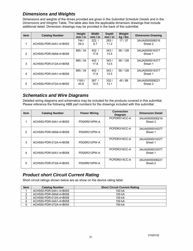
Dimensions and Weights Dimensions and weights of the drives provided are given in the Submittal Schedule Details and in the Dimensions and Weights Table. The table also lists the applicable dimension drawings that include additional detail. Dimension drawings may be provided in the back of this submittal. Item Catalog Number
Height mm / in
Width mm / in
Depth mm / in
Weight kg / lbs
Dimension Drawing
1 ACH550-PDR-04A1-4+B055 744 / 29.3
222 / 8.7
283 / 11.2
17 / 37 3AUA0000008216 Sheet 2
2 ACH550-PDR-08A8-4+B058 865 / 34 452 /
17.8 343 / 13.5
58 / 128 3AUA0000016377 Sheet 1
3 ACH550-PDR-012A-4+B058 865 / 34 452 /
17.8 343 / 13.5
58 / 128 3AUA0000016377 Sheet 1
4 ACH550-PDR-04A1-4+B058 865 / 34 452 /
17.8 343 / 13.5
58 / 128 3AUA0000016377 Sheet 1
5 ACH550-PDR-072A-4+B055 1163 / 45.8
267 / 10.5
332 / 13.1
45 / 99 3AUA0000008221 Sheet 2
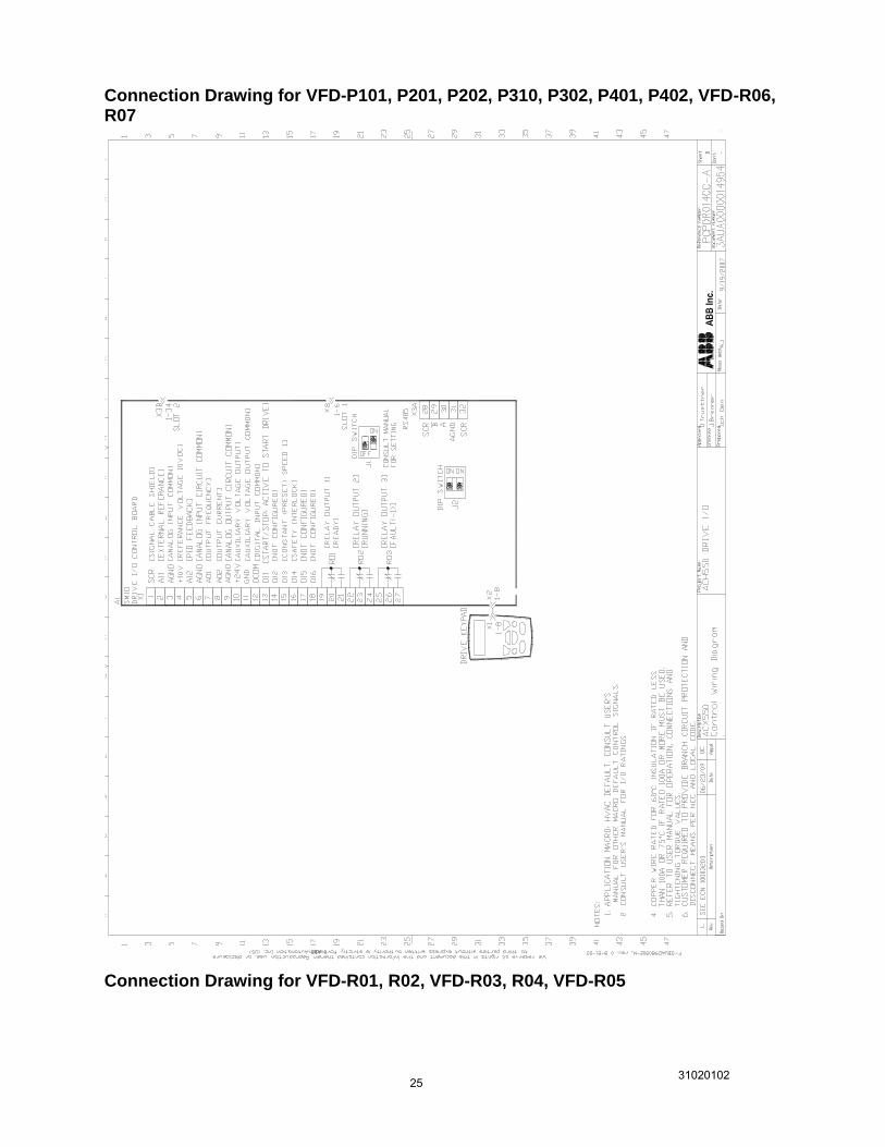
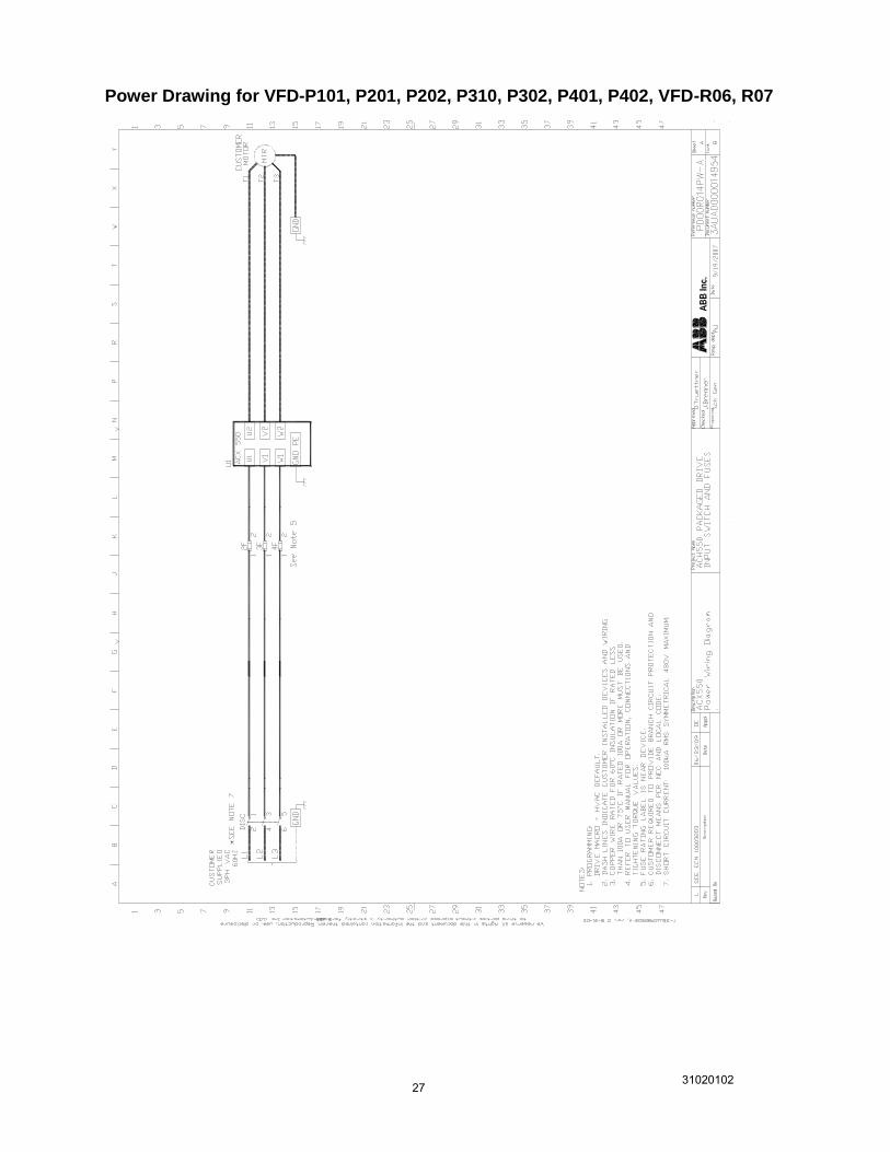
Schematics and Wire Diagrams Detailed wiring diagrams and schematics may be included for the products covered in this submittal. Please reference the following ABB part numbers for the drawings included with this submittal: Item Catalog Number Power Wiring
Connection Diagram
Dimension Detail
1 ACH550-PDR-04A1-4+B055 PD00R014PW-A PCPDR014CC-A
3AUA0000008216 Sheet 2
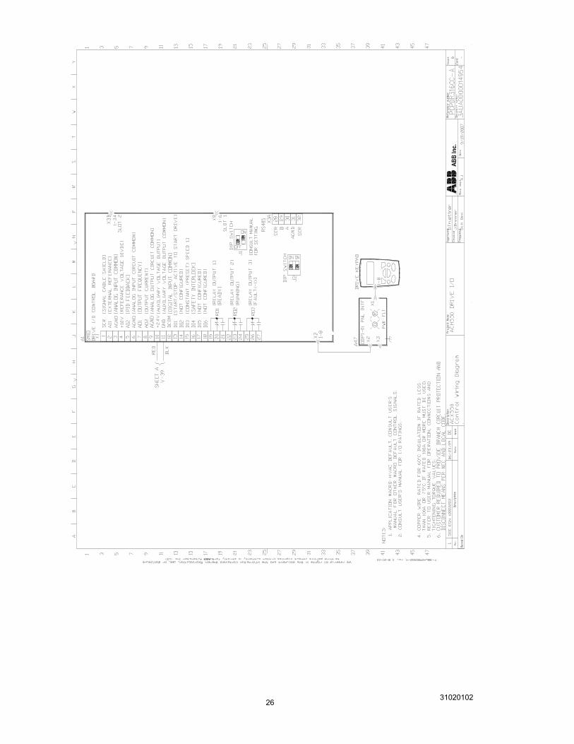
2 ACH550-PDR-08A8-4+B058 PD00R312PW-A PCPDR316CC-A
3AUA0000016377 Sheet 1
3 ACH550-PDR-012A-4+B058 PD00R312PW-A PCPDR316CC-A
3AUA0000016377 Sheet 1
4 ACH550-PDR-04A1-4+B058 PD00R312PW-A PCPDR316CC-A
3AUA0000016377 Sheet 1
5 ACH550-PDR-072A-4+B055 PD00R014PW-A PCPDR014CC-A
3AUA0000008221 Sheet 2
Product short Circuit Current Rating Short circuit ratings shown below are as show on the device rating label. Item Catalog Number Short Circuit Current Rating
1 ACH550-PDR-04A1-4+B055 100 kA 2 ACH550-PDR-08A8-4+B058 100 kA 3 ACH550-PDR-012A-4+B058 100 kA 4 ACH550-PDR-04A1-4+B058 100 kA 5 ACH550-PDR-072A-4+B055 100 kA
31020102 22
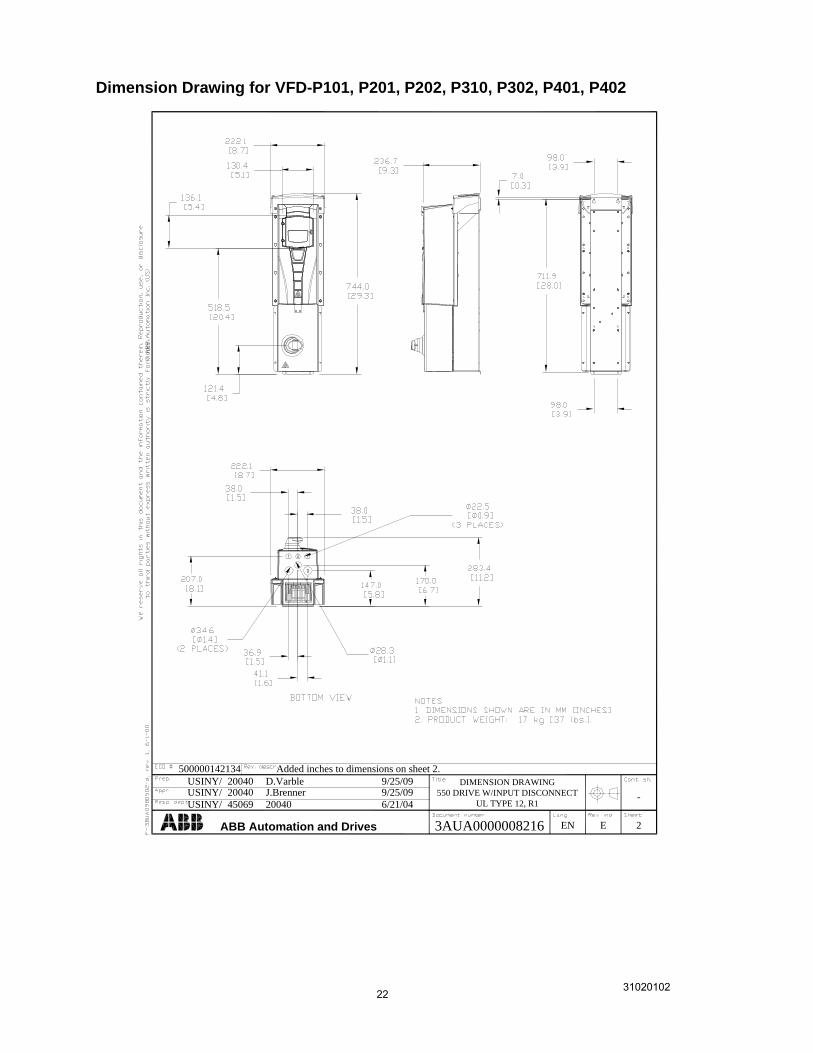
Dimension Drawing for VFD-P101, P201, P202, P310, P302, P401, P402
ABB Automation and Drives
USINY/USINY/
USINY/
20040 D.Varble 9/25/0920040 J.Brenner 9/25/09
45069 20040 6/21/04
DIMENSION DRAWING
550 DRIVE W/INPUT DISCONNECT
UL TYPE 12, R1
2
-
3AUA0000008216 EN E
500000142134 Added inches to dimensions on sheet 2.
31020102 23
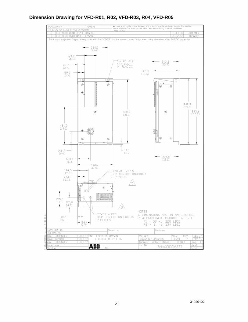
Dimension Drawing for VFD-R01, R02, VFD-R03, R04, VFD-R05
31020102 24
Dimension Drawing for VFD-R06, R07
ABB Automation and Drives
USINY/USINY/
USINY/
20040 D.Varble 9/25/0920040 J.Brenner 9/25/09
45069 20040 6/21/04
DIMENSION DRAWING
550 DRIVE W/INPUT DISCONNECT
UL TYPE 12, R4
2
-
3AUA0000008221 EN E
500000142134 Added inches to dimensions on sheet 2.
31020102 25
Connection Drawing for VFD-P101, P201, P202, P310, P302, P401, P402, VFD-R06, R07
Connection Drawing for VFD-R01, R02, VFD-R03, R04, VFD-R05
31020102 26
31020102 27
Power Drawing for VFD-P101, P201, P202, P310, P302, P401, P402, VFD-R06, R07
31020102 28
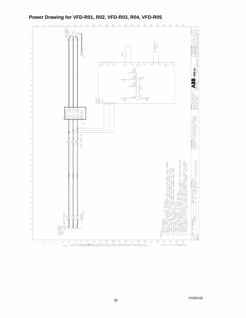
Power Drawing for VFD-R01, R02, VFD-R03, R04, VFD-R05