Embed Size (px)
DESCRIPTION
The ABC's of Physical Metallurgy
Citation preview
METALLURGY TRAINING MODULE ! REV. A01
BY
JDD
DATE
10/06/12 The ABC’s of Physical Metallurgy
Page 1 of 15 APPROVED
DATE
Introduction
Physical metallurgy is the study of the properties and behavior of metals as a function of their microstructure. A physical metallurgist is one who can manipulate a metal’s microstructure through alloying, heat treating, or other special processes in order to obtain some desired set of properties. In this training module we are going to look at some of the basic principles of physical metallurgy at an atomic level. An understanding of what goes on at an atomic level will help to explain why metals behave the way they do on a macroscopic level. A heavy dose of theory is necessary before we get to the more practical aspects of metallurgy. This module is the foundation on which all others will be built. You can moan and groan now and wonder “Why do I need to know all this stuff?’ The answer will soon become apparent as you proceed through the other modules that constantly refer back to the ABC’s of Physical Metallurgy!
Metals
All of us can recognize a metal when we see one. A metal can be defined empirically as a substance that has metallic properties: it’s generally hard, shiny, a good conductor of heat and electricity, has good strength, and is ductile and malleable. Of course these traits are relative to other substances and may vary considerably amongst metals themselves. Chemists define metals as substances that go into solution as positive ions and whose oxides tend to form hydroxides rather than acids with water. A metallurgist will define a metal as a substance whose valence electrons are shared between many nuclei and are free to move around. The attraction between the negative electron “cloud” and the positive nuclei is what holds the whole thing together. In other words, metals are substances held together by metallic bonds. Metallic elements make up about ¾ of the periodic table. Think of the metals used at ARGUS Subsea. There are very few applications for pure or elemental metals because of their limited properties from an engineering standpoint. Most metals used in the Oil Patch are alloys. An alloy is a substance that has metallic properties and consists of two or more elements at least one of which is a metal. Note just because a substance contains an element that is a metal does not make that substance a metal: the combination of elements must have metallic properties. For example, alumina (Al2O3) contains aluminum which is a metal, but because alumina is brittle and is a very poor conductor of heat and electricity, it is not classified as a metal. It is rather classified as a ceramic. By far the most important alloy family in our industry is steels. Steel by definition is an alloy of iron (a metal) and carbon (a non-metal). There are of course many different alloys of steels with a wide range of alloying elements, but they are all based upon the iron-carbon system. Steel may contain up to roughly 2% carbon by weight (all the percentages in this module are by weight). An iron based material containing more than 2% carbon is classified as a cast iron. We’ll focus on steels in this module
METALLURGY TRAINING MODULE ! REV. A01
BY
JDD
DATE
10/06/12 The ABC’s of Physical Metallurgy
Page 2 of 15 APPROVED
DATE
because of their engineering importance, but many of the basic principles you’ll be learning about apply to other metals as well.
The Microstructure of Steel
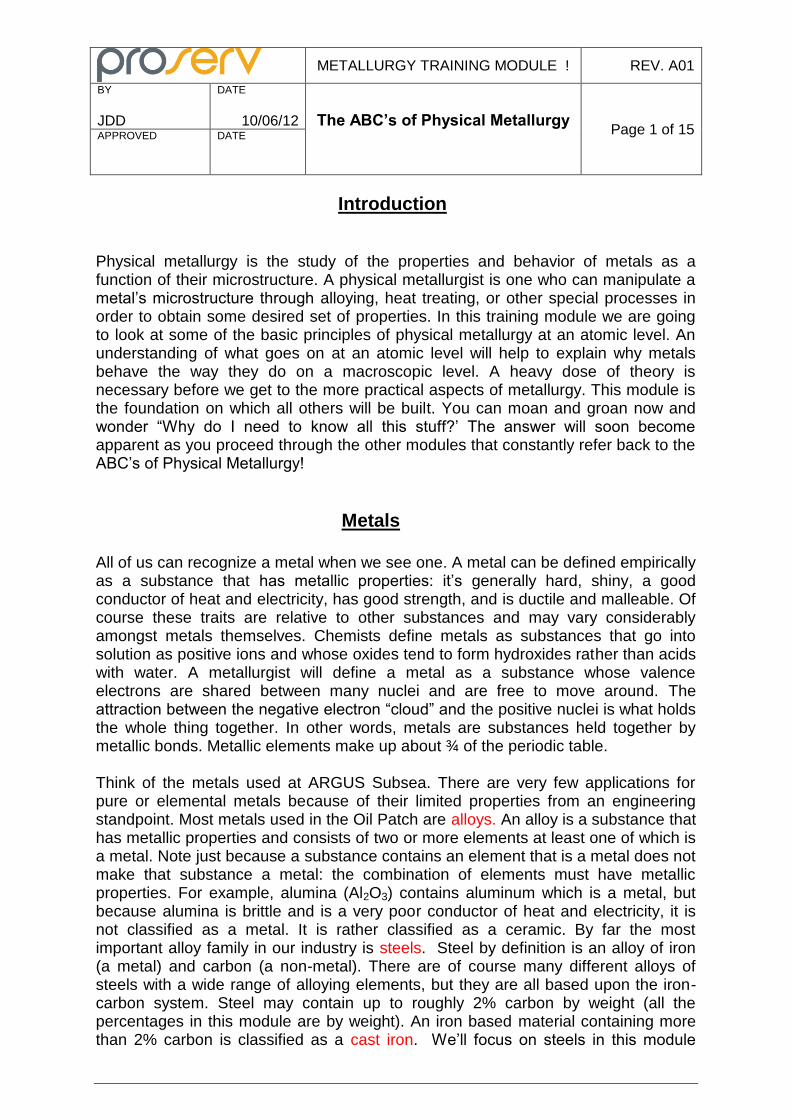
As stated in the Introduction, the properties of a metal are strongly dependent on its microstructure. What exactly is a “microstructure”? It’s basically what you see under a microscope at high magnification on a metal sample that has been polished to a mirror finish and then lightly etched with an acid to bring out the surface highlights. Figure 1 shows the microstructure of a plain carbon steel with 0.20% carbon at about 650X.
Figure 1: Microstructure of a Plain Carbon Steel With 0.20% Carbon
The first thing to notice in Figure 1 is that there are many sub-areas delineated by black lines. These black lines are grain boundaries and the areas they enclose are grains or crystals. Metals are crystalline substances with only a few exceptions. Typically they are polycrystalline (contain many crystals), but single crystal metals do exist and are used in specialized applications (jet turbine blades for example). The size, shape, and orientation of these crystals play a very important role in determining the properties of a metal. The next thing to notice is that not all the grains look alike: some are light color and some are dark. This is because the grains may consist of different substances called phases. The type, amount, size, and
METALLURGY TRAINING MODULE ! REV. A01
BY
JDD
DATE
10/06/12 The ABC’s of Physical Metallurgy
Page 3 of 15 APPROVED
DATE
distribution of phases also help determine the properties of a metal. Grains and phases: we’ll spend a lot of time discussing these two parameters and how they can be manipulated to properties we want in our metal.
Crystals
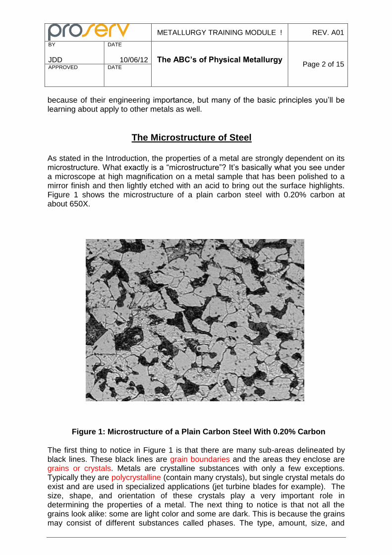
You’re already familiar with crystals. The sugar you added to your coffee this morning is crystalline. Salt is crystalline. The diamond in a wedding ring is a crystal. What do these have in common with the crystals (or grains as metallurgists like to call them) shown in Figure 1? At first glance not much! But when you get down to an atomic level you’ll notice that in each of these substances, including our plain carbon steel, the atoms have arranged themselves into a specific pattern that is repeated over and over in all three dimensions. A crystal then is an orderly array of atoms. The specific arrangement or pattern of atoms is called the lattice structure. The smallest repeating unit is called the unit cell. Many metals have a lattice based upon a cubic structure: a metal atom is located at each corner of a cube and that pattern is repeated over and over in three dimensions. One atom is thus shared between 8 individual cubic unit cells. Iron is rather unique in that it has two different types of cubic crystal structures that are stable over different temperature ranges. At temperatures up to 1677F, iron has a body centered cubic or BCC structure (see Figure 2). This consists of a cubic structure with an iron atom at each corner plus an iron atom in the center of the cube. Each BCC unit cell contains 2 atoms (remember the corner atoms are shared by 8 cells). Iron having an BCC structure is called alpha iron. It is often abbreviated with the small Greek letter alpha – α. Figure 2: Body Centered Cubic (BCC) Structure
METALLURGY TRAINING MODULE ! REV. A01
BY
JDD
DATE
10/06/12 The ABC’s of Physical Metallurgy
Page 4 of 15 APPROVED
DATE
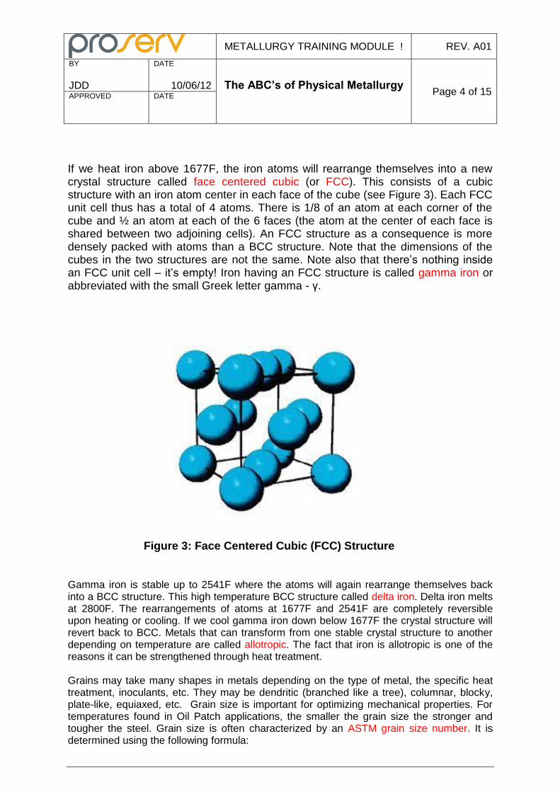
If we heat iron above 1677F, the iron atoms will rearrange themselves into a new crystal structure called face centered cubic (or FCC). This consists of a cubic structure with an iron atom center in each face of the cube (see Figure 3). Each FCC unit cell thus has a total of 4 atoms. There is 1/8 of an atom at each corner of the cube and ½ an atom at each of the 6 faces (the atom at the center of each face is shared between two adjoining cells). An FCC structure as a consequence is more densely packed with atoms than a BCC structure. Note that the dimensions of the cubes in the two structures are not the same. Note also that there’s nothing inside an FCC unit cell – it’s empty! Iron having an FCC structure is called gamma iron or abbreviated with the small Greek letter gamma - γ.
Figure 3: Face Centered Cubic (FCC) Structure
Gamma iron is stable up to 2541F where the atoms will again rearrange themselves back into a BCC structure. This high temperature BCC structure called delta iron. Delta iron melts at 2800F. The rearrangements of atoms at 1677F and 2541F are completely reversible upon heating or cooling. If we cool gamma iron down below 1677F the crystal structure will revert back to BCC. Metals that can transform from one stable crystal structure to another depending on temperature are called allotropic. The fact that iron is allotropic is one of the reasons it can be strengthened through heat treatment. Grains may take many shapes in metals depending on the type of metal, the specific heat treatment, inoculants, etc. They may be dendritic (branched like a tree), columnar, blocky, plate-like, equiaxed, etc. Grain size is important for optimizing mechanical properties. For temperatures found in Oil Patch applications, the smaller the grain size the stronger and tougher the steel. Grain size is often characterized by an ASTM grain size number. It is determined using the following formula:
METALLURGY TRAINING MODULE ! REV. A01
BY
JDD
DATE
10/06/12 The ABC’s of Physical Metallurgy
Page 5 of 15 APPROVED
DATE
N = 2 (n-1)
Where N = the number of grains per square inch at 100X magnification n = the ASTM grain size number Notice that the larger the ASTM grain size number, the more grains there are per unit area and hence the smaller the grains. ARGUS Subsea material specifications for steels all require a “fine grain” melting practice. By definition, a fine grain size is ASTM #5 or larger. If we plug 5 back into our formula we get N = 16. To find the number of grains in a square inch, we have to multiply this by 10,000 (100 X 100) because the area under consideration is being viewed at 100X. We thus have a minimum of 160,000 grains per square inch in our steel. Grain size can be controlled through alloying additions; controlling the amount of working, and through heat treatment. Grains can grow at high temperatures with the large grains growing at the expense of smaller ones.
Phases
A phase is a homogeneous substance that is physically distinct from other surrounding substances. Homogeneous means that any individual sample taken from the substance is chemically and physically identical to any other sample taken from the substance. Consider a glass of water. Water is the liquid phase of H20. No matter where we sample the water in the glass, it will be chemically and physically identical to any other water sample taken from the glass. Water of course has other phases. Ice is the solid phase. Steam or water vapor is the gaseous phase. Metals, besides having liquid and gaseous phases, may have more than one solid phase. Each crystal structure of iron (BCC or FCC), for example, is a separate solid phase. The types, amounts, and distribution of the phases that are present in a metal are very important because each phase can have significantly different properties. Our glass of water is a one phase system (ignoring the glass itself!). If we add an ice cube into it we now have a two phase system. Note we haven’t altered the composition – it’s all just H20 – yet the two phases have vastly different properties. We can control the amount of ice in our glass at any instance of time by raising or lowering the temperature. Let the ice melt and we’re back to a one phase system. Now take a teaspoon of sugar and stir in the glass until it all dissolves. Now how many phases are present? Still just one. We altered the composition of the water in the glass, but because the resulting sugar solution is chemically and physically identical no matter where we sample, it is still a single phase. If we keep adding sugar and stirring, eventually we will reach a point where the solution becomes saturated with sugar. No matter how much we stir, no more sugar will go into solution. If we add more, it will sink to the bottom of the glass as solid granules. At this point we now have a two phase system in our glass. Thus we have learned a second way to control the types and relative amounts of phases in a system: we can alter the composition. The same holds true for metals. We can control the types and relative amounts of phases present in a metal by raising or lowering the temperature (heat treating) and by altering the metal’s composition (alloying).
METALLURGY TRAINING MODULE ! REV. A01
BY
JDD
DATE
10/06/12 The ABC’s of Physical Metallurgy
Page 6 of 15 APPROVED
DATE
Our glass of water with sugar dissolved in it is an example of a liquid solution. The continuous matrix of water is called the solvent and the dissolved sugar is the solute. Solids can also form solutions. Steel is essentially a solid solution of carbon atoms (the solute) dissolved in a matrix of iron atoms (the solvent). A carbon atom is relatively small compared to an iron atom. It can be accommodated or dissolved within the BCC or FCC iron crystal structure in small quantities without causing any distortion of the lattice. BCC iron that contains carbon in solid solution is called ferrite. FCC iron that contains carbon in solid solution is called austenite. Just as there is a limit to the amount of sugar we can add to our glass of water before the solution becomes saturated, there is a limit to the amount of carbon we can dissolve into a BCC or FCC crystal structure: we can only add so much before it becomes saturated and another phase will form. The new phase that will form if we keep adding carbon beyond the saturation point is called cementite. As the name implies, it is hard and strong and is one of the chief hardening agents in steel. Cementite has a stoichiometric formula of Fe3C. The maximum solubility of carbon in austenite is a little over 2% while that in ferrite is less than 0.02% (the maximum solubility is temperature dependent). That’s a big difference. Think of the BCC structure of ferrite and the FCC structure of austenite as boxes. The BCC box has a big iron atom in the center of it while the center of the FCC box is empty. The FCC box can thus hold more carbon atoms than the BCC box. The ferrite-to-austenite phase transformation that takes place upon heating (or austenite-to-ferrite upon cooling) along with the difference in carbon solubility between BCC and FCC structures are they keys to understanding the versatility of steels and how they can be heat treated to such a wide range of properties.
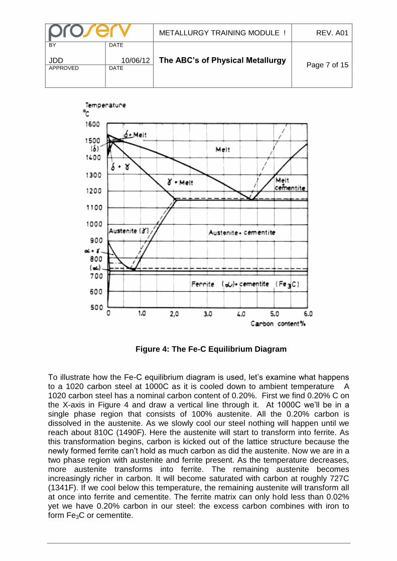
The phases present in a simple carbon steel are dependent on temperature and carbon content. The Fe-C equilibrium (or phase) diagram (see Figure 4) is essentially a map showing what phases are present as a function of temperature (Y-axis) and carbon content (X-axis). It’s called an equilibrium diagram because any transition from one temperature to another is done very slowly to allow any possible changes to occur until completion – or equilibrium is reached. In Figure 4 the small Greek letter α (alpha) is used as a symbol to represent ferrite, the small Greek letter γ (gamma) for austenite, and the small Greek letter δ for delta phase (BCC) that forms at high temperatures. A horizontal line on the diagram is called an isotherm. The horizontal line at 727C (1341F) is called the eutectoid isotherm and the point on the line at 0.77% C is called the eutectoid point. The horizontal line at 1148C (2098F) is called the eutectic isotherm and the point on the line at 4.30% C is called the eutectic point. Note that the eutectic point represents the only place where a solid alloy of iron and carbon (consisting of ferrite and cementite) will melt upon heating into a liquid at a single temperature: at non-eutectic carbon contents, melting takes place over a range of temperatures. Similarly the eutectoid point is the only place on the diagram where a single solid phase (consisting of ferrite and cementite) transforms upon heating directly into austenite at a single temperature. Non-eutectoid compositions will transform over a range of temperatures.
METALLURGY TRAINING MODULE ! REV. A01
BY
JDD
DATE
10/06/12 The ABC’s of Physical Metallurgy
Page 7 of 15 APPROVED
DATE
Figure 4: The Fe-C Equilibrium Diagram
To illustrate how the Fe-C equilibrium diagram is used, let’s examine what happens to a 1020 carbon steel at 1000C as it is cooled down to ambient temperature A 1020 carbon steel has a nominal carbon content of 0.20%. First we find 0.20% C on the X-axis in Figure 4 and draw a vertical line through it. At 1000C we’ll be in a single phase region that consists of 100% austenite. All the 0.20% carbon is dissolved in the austenite. As we slowly cool our steel nothing will happen until we reach about 810C (1490F). Here the austenite will start to transform into ferrite. As this transformation begins, carbon is kicked out of the lattice structure because the newly formed ferrite can’t hold as much carbon as did the austenite. Now we are in a two phase region with austenite and ferrite present. As the temperature decreases, more austenite transforms into ferrite. The remaining austenite becomes increasingly richer in carbon. It will become saturated with carbon at roughly 727C (1341F). If we cool below this temperature, the remaining austenite will transform all at once into ferrite and cementite. The ferrite matrix can only hold less than 0.02% yet we have 0.20% carbon in our steel: the excess carbon combines with iron to form Fe3C or cementite.
METALLURGY TRAINING MODULE ! REV. A01
BY
JDD
DATE
10/06/12 The ABC’s of Physical Metallurgy
Page 8 of 15 APPROVED
DATE
What will our 1020 carbon steel microstructure look like at room temperature? Go back and look at Figure 1 and you’ll see! We can now discuss the different features in Figure 1 in some detail. The light colored grains or crystals are proeutectoid ferrite: ferrite that formed above the eutectoid isotherm. As the proeutectoid ferrite forms, the remaining austenite becomes richer and richer in carbon. The austenite becomes saturated just above the eutectoid isotherm. The carbon saturated austenite will transform at a single temperature into ferrite and cementite as it dips below 727C (1341F). This transformation is easily recognizable in Figure 1 as the dark colored grains. The grains appear dark because they consist of alternating bands of ferrite (light colored) and cementite (dark colored). These dark grains are called pearlite. Pearlite is not a phase of steel (it obviously not homogeneous!), but it is a recognizable microconstituent. Pearlite is significantly harder and stronger than ferrite. It is a natural composite having alternating bands (platelets) of hard, brittle cementite reinforcing the soft, ductile ferrite. Pearlite is the decomposition product of austenite of eutectoid composition.
Crystal Imperfections
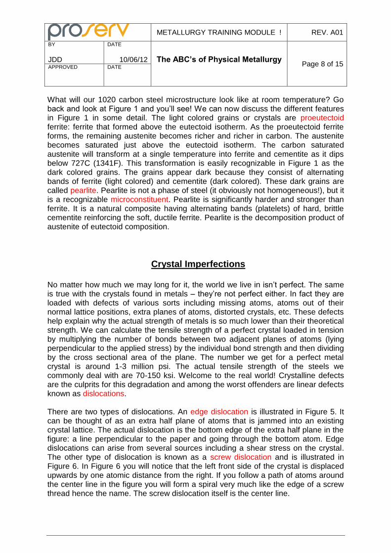
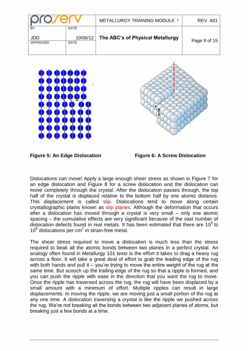
No matter how much we may long for it, the world we live in isn’t perfect. The same is true with the crystals found in metals – they’re not perfect either. In fact they are loaded with defects of various sorts including missing atoms, atoms out of their normal lattice positions, extra planes of atoms, distorted crystals, etc. These defects help explain why the actual strength of metals is so much lower than their theoretical strength. We can calculate the tensile strength of a perfect crystal loaded in tension by multiplying the number of bonds between two adjacent planes of atoms (lying perpendicular to the applied stress) by the individual bond strength and then dividing by the cross sectional area of the plane. The number we get for a perfect metal crystal is around 1-3 million psi. The actual tensile strength of the steels we commonly deal with are 70-150 ksi. Welcome to the real world! Crystalline defects are the culprits for this degradation and among the worst offenders are linear defects known as dislocations. There are two types of dislocations. An edge dislocation is illustrated in Figure 5. It can be thought of as an extra half plane of atoms that is jammed into an existing crystal lattice. The actual dislocation is the bottom edge of the extra half plane in the figure: a line perpendicular to the paper and going through the bottom atom. Edge dislocations can arise from several sources including a shear stress on the crystal. The other type of dislocation is known as a screw dislocation and is illustrated in Figure 6. In Figure 6 you will notice that the left front side of the crystal is displaced upwards by one atomic distance from the right. If you follow a path of atoms around the center line in the figure you will form a spiral very much like the edge of a screw thread hence the name. The screw dislocation itself is the center line.
METALLURGY TRAINING MODULE ! REV. A01
BY
JDD
DATE
10/06/12 The ABC’s of Physical Metallurgy
Page 9 of 15 APPROVED
DATE
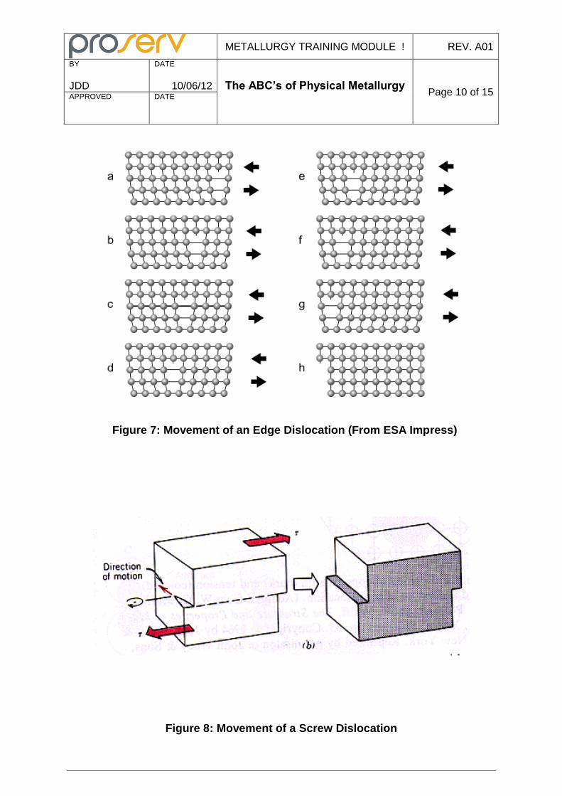
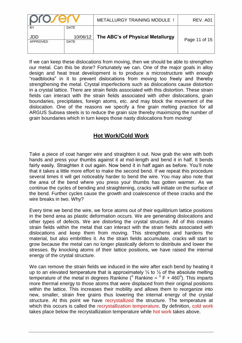
Figure 5: An Edge Dislocation Figure 6: A Screw Dislocation Dislocations can move! Apply a large enough sheer stress as shown in Figure 7 for an edge dislocation and Figure 8 for a screw dislocation and the dislocation can move completely through the crystal. After the dislocation passes through, the top half of the crystal is displaced relative to the bottom half by one atomic distance. This displacement is called slip. Dislocations tend to move along certain crystallographic plains known as slip planes. Although the deformation that occurs after a dislocation has moved through a crystal is very small – only one atomic spacing – the cumulative effects are very significant because of the vast number of dislocation defects found in real metals. It has been estimated that there are 10
6 to
108 dislocations per cm
2 in strain-free metal.
The shear stress required to move a dislocation is much less than the stress required to beak all the atomic bonds between two planes in a perfect crystal. An analogy often found in Metallurgy 101 texts is the effort it takes to drag a heavy rug across a floor. It will take a great deal of effort to grab the leading edge of the rug with both hands and pull it – you’re trying to move the entire weight of the rug at the same time. But scooch up the trailing edge of the rug so that a ripple is formed, and you can push the ripple with ease in the direction that you want the rug to move. Once the ripple has traversed across the rug, the rug will have been displaced by a small amount with a minimum of effort. Multiple ripples can result in large displacements. In moving the ripple, we are moving just a small portion of the rug at any one time. A dislocation traversing a crystal is like the ripple we pushed across the rug. We’re not breaking all the bonds between two adjacent planes of atoms, but breaking just a few bonds at a time.
METALLURGY TRAINING MODULE ! REV. A01
BY
JDD
DATE
10/06/12 The ABC’s of Physical Metallurgy
Page 10 of 15 APPROVED
DATE
Figure 7: Movement of an Edge Dislocation (From ESA Impress)
Figure 8: Movement of a Screw Dislocation
METALLURGY TRAINING MODULE ! REV. A01
BY
JDD
DATE
10/06/12 The ABC’s of Physical Metallurgy
Page 11 of 15 APPROVED
DATE
If we can keep these dislocations from moving, then we should be able to strengthen our metal. Can this be done? Fortunately we can. One of the major goals in alloy design and heat treat development is to produce a microstructure with enough “roadblocks” in it to prevent dislocations from moving too freely and thereby strengthening the metal. Crystal imperfections such as dislocations cause distortion in a crystal lattice. There are strain fields associated with this distortion. These strain fields can interact with the strain fields associated with other dislocations, grain boundaries, precipitates, foreign atoms, etc. and may block the movement of the dislocation. One of the reasons we specify a fine grain melting practice for all ARGUS Subsea steels is to reduce the grain size thereby maximizing the number of grain boundaries which in turn keeps those nasty dislocations from moving!
Hot Work/Cold Work
Take a piece of coat hanger wire and straighten it out. Now grab the wire with both hands and press your thumbs against it at mid-length and bend it in half. It bends fairly easily. Straighten it out again. Now bend it in half again as before. You’ll note that it takes a little more effort to make the second bend. If we repeat this procedure several times it will get noticeably harder to bend the wire. You may also note that the area of the bend where you press your thumbs has gotten warmer. As we continue the cycles of bending and straightening, cracks will initiate on the surface of the bend. Further cycles cause the growth and coalescence of these cracks and the wire breaks in two. Why? Every time we bend the wire, we force atoms out of their equilibrium lattice positions in the bend area as plastic deformation occurs. We are generating dislocations and other types of defects. We are distorting the crystal structure. All of this creates strain fields within the metal that can interact with the strain fields associated with dislocations and keep them from moving. This strengthens and hardens the material, but also embrittles it. As the strain fields accumulate, cracks will start to grow because the metal can no longer plastically deform to distribute and lower the stresses. By knocking atoms of their lattice positions, we have raised the internal energy of the crystal structure. We can remove the strain fields we induced in the wire after each bend by heating it up to an elevated temperature that is approximately ⅓ to ½ of the absolute melting temperature of the metal in degrees Rankine (
o Rankine =
o F + 460
o). This imparts
more thermal energy to those atoms that were displaced from their original positions within the lattice. This increases their mobility and allows them to reorganize into new, smaller, strain free grains thus lowering the internal energy of the crystal structure. At this point we have recrystallized the structure. The temperature at which this occurs is called the recrystallization temperature. By definition, cold work takes place below the recrystallization temperature while hot work takes above.
METALLURGY TRAINING MODULE ! REV. A01
BY
JDD
DATE
10/06/12 The ABC’s of Physical Metallurgy
Page 12 of 15 APPROVED
DATE
When metals are forged, rolled, spun, etc. to produce a given shape, it is generally done above their recrystallization temperature. In other words, they are hot worked. Steels are typically forged around 2100F. There are several reasons for this. First is that strains induced by plasitically deforming the metal will not accumulate: they will in fact dissipate as the metal instantly recrystallizes. This prevents the part from cracking during forging. Second is that the metal’s strength and hardness are much lower at high temperatures so less power is needed to physically move the material around into the desired shape. And finally it saves wear and tear on the expensive dies used to shape the metal. Certain types of metals cannot be strengthened by heat treatment. The austenitic stainless steels, 316 for example, are alloyed so that they always have a FCC (austenitic) structure up to their melting point. Many nickel base alloys such as 825 and 625 also have an FCC structure up to their melting points. While these types of metals can’t be heat treated to higher strengths, they can be cold worked to higher strengths. There are some issues associated with cold working that you need to be aware of. While the strengthening effects of cold working may be fairly uniform throughout the cross section of a 2” diameter bar, this won’t be the case in a 6” diameter bar. The material closest to the OD in the larger bar will undergo more cold work than the center. The strength and the hardness will decrease from OD to center. A finished part machined from a cold work bar may not have the desired mechanical properties because all the good stuff lies as chips on the floor. There may be some distortion if the bar is not evenly machined (milled deeper on one side than the other for example). This causes an imbalance in the residual stresses in the bar. Cold worked parts can be welded, but the weldment design must take into account the decrease in strength in the heat affected zone adjacent to the weld. The high temperatures associated with welding will cause the metal to recrystallizes and lose strength. Finally cold working enhances many metals’ susceptibility to a type of catastrophic failure known as environmentally assisted cracking. For example NACE prohibits cold working austenitic stainless steels to increase their strength if they will be used in sour service because cold working makes them more susceptible to H2S stress cracking. Many bars are produced using a combination of hot and cold working. They are hot worked during the rolling operations where heavy reductions are taking place. When they are near final size, they’ll undergo a final, cold working pass (note cold work does not necessarily work done at room temperature!).This gives them a better surface finish and the residual stresses imparted help maintain straightness within the tolerance limits. It is sometimes necessary to impart incidental cold work (not intentionally done to enhance the strength) during fabrication of a metal assembly. For example small diameter steel pipe may be cold bent into the shape when making a manifold. If the resulting cold work would be detrimental to the performance of the part, it can be removed by stress relieving. Stress relieving involves reheating the part above its recrystallization temperature for a brief period of time. Carbon and low alloy steels are typically stress relieved at a minimum of 1100F. The maximum allowed stress relief temperature is kept 25-50F below their
METALLURGY TRAINING MODULE ! REV. A01
BY
JDD
DATE
10/06/12 The ABC’s of Physical Metallurgy
Page 13 of 15 APPROVED
DATE
original tempering temperature so the stress relief does adversely impact the bulk properties of the steel.
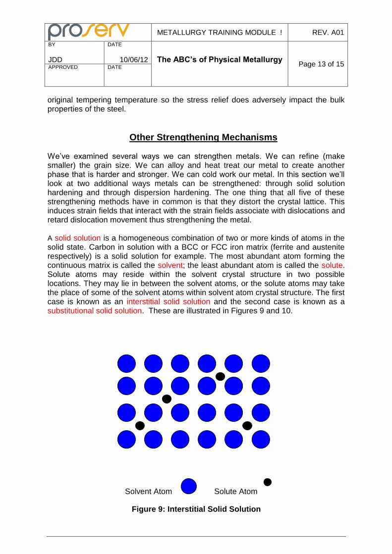
Other Strengthening Mechanisms We’ve examined several ways we can strengthen metals. We can refine (make smaller) the grain size. We can alloy and heat treat our metal to create another phase that is harder and stronger. We can cold work our metal. In this section we’ll look at two additional ways metals can be strengthened: through solid solution hardening and through dispersion hardening. The one thing that all five of these strengthening methods have in common is that they distort the crystal lattice. This induces strain fields that interact with the strain fields associate with dislocations and retard dislocation movement thus strengthening the metal. A solid solution is a homogeneous combination of two or more kinds of atoms in the solid state. Carbon in solution with a BCC or FCC iron matrix (ferrite and austenite respectively) is a solid solution for example. The most abundant atom forming the continuous matrix is called the solvent; the least abundant atom is called the solute. Solute atoms may reside within the solvent crystal structure in two possible locations. They may lie in between the solvent atoms, or the solute atoms may take the place of some of the solvent atoms within solvent atom crystal structure. The first case is known as an interstitial solid solution and the second case is known as a substitutional solid solution. These are illustrated in Figures 9 and 10.
Solvent Atom Solute Atom
Figure 9: Interstitial Solid Solution
METALLURGY TRAINING MODULE ! REV. A01
BY
JDD
DATE
10/06/12 The ABC’s of Physical Metallurgy
Page 14 of 15 APPROVED
DATE
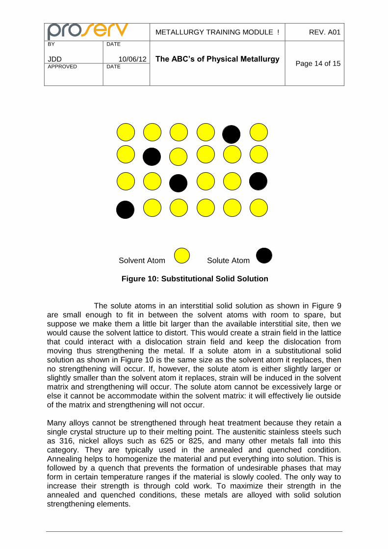
Solvent Atom Solute Atom
Figure 10: Substitutional Solid Solution The solute atoms in an interstitial solid solution as shown in Figure 9 are small enough to fit in between the solvent atoms with room to spare, but suppose we make them a little bit larger than the available interstitial site, then we would cause the solvent lattice to distort. This would create a strain field in the lattice that could interact with a dislocation strain field and keep the dislocation from moving thus strengthening the metal. If a solute atom in a substitutional solid solution as shown in Figure 10 is the same size as the solvent atom it replaces, then no strengthening will occur. If, however, the solute atom is either slightly larger or slightly smaller than the solvent atom it replaces, strain will be induced in the solvent matrix and strengthening will occur. The solute atom cannot be excessively large or else it cannot be accommodate within the solvent matrix: it will effectively lie outside of the matrix and strengthening will not occur. Many alloys cannot be strengthened through heat treatment because they retain a single crystal structure up to their melting point. The austenitic stainless steels such as 316, nickel alloys such as 625 or 825, and many other metals fall into this category. They are typically used in the annealed and quenched condition. Annealing helps to homogenize the material and put everything into solution. This is followed by a quench that prevents the formation of undesirable phases that may form in certain temperature ranges if the material is slowly cooled. The only way to increase their strength is through cold work. To maximize their strength in the annealed and quenched conditions, these metals are alloyed with solid solution strengthening elements.
METALLURGY TRAINING MODULE ! REV. A01
BY
JDD
DATE
10/06/12 The ABC’s of Physical Metallurgy
Page 15 of 15 APPROVED
DATE
Dispersion strengthening is the last method of strengthening we’ll discuss. It consists of forming a supersaturated solid solution of two or more elements by annealing at a high temperature followed by rapid cooling. The material is then reheated to a lower temperature and held allowing a second phase to come out of solution as a finely dispersed precipitate.. These hard precipitates impede dislocation movement by effectively “pinning” the dislocation in place. They also create cause lattice distortions that introduce strain fields into the matrix that will also interfere with dislocation movement. Alloys such 17-4 PH™ stainless steel and nickel alloys 718, 925, 725, and 945 achieve very high yield strength through dispersion hardening. Dispersion hardened alloys are also referred to as “age hardenable” or “precipitation hardenable” alloys. The most effective hardening will occur when the particles are finely dispersed throughout the matrix and are of optimum size. Too small, the precipitates may not generate the required strain fields. Too large, the precipitates may effectively lie outside the matrix and not generate the required strain fields. It takes an electron microscope to see properly sized precipitates: if you can see them under a light microscope they are already too big!


![[Robert E. Reed-Hill] Physical Metallurgy Principl](https://img.pdfslide.us/doc/110x75/55cf900b550346703ba29c12/robert-e-reed-hill-physical-metallurgy-principl.jpg)


![1 Physical Metallurgy- Solid Solution[1]](https://img.pdfslide.us/doc/110x75/54f96d114a79599d368b4609/1-physical-metallurgy-solid-solution1.jpg)