Embed Size (px)
Citation preview


The ABCsof
IP Addressing

ABCs of IP AddressingGilbert HeldISBN: 0-8493-1144-6
Application Servers for E-BusinessLisa M. LindgrenISBN: 0-8493-0827-5
Architectures for e-BusinessSanjiv Purba, EditorISBN: 0-8493-1161-6
A Technical Guide to IPSec VirtualPrivate NetworksJames S. TillerISBN: 0-8493-0876-3
Building an Information SecurityAwareness ProgramMark B. DesmanISBN: 0-8493-0116-5
Computer Telephony IntegrationWilliam Yarberry, Jr.ISBN: 0-8493-9995-5
Cyber Crime Field HandbookBruce MiddletonISBN: 0-8493-1192-6
Enterprise Systems ArchitecturesMark Goodyear, EditorISBN: 0-8493-9836-3
Enterprise Systems Integration,2nd EditionJudith MyersonISBN: 0-8493-1149-7
Information Security ArchitectureJan Killmeyer TudorISBN: 0-8493-9988-2
Information Security ManagementHandbook, 4th Edition, Volume 2Harold F. Tipton and Micki Krause, EditorsISBN: 0-8493-0800-3
Information Security ManagementHandbook, 4th Edition, Volume 3Harold F. Tipton and Micki Krause, EditorsISBN: 0-8493-1127-6
Information Security Policies,Procedures, and Standards: Guidelinesfor Effective Information SecurityThomas PeltierISBN: 0-8493-1137-3
Information Security Risk AnalysisThomas PeltierISBN: 0-8493-0880-1
Information Technology Controland AuditFrederick Gallegos, Sandra Allen-Senft,and Daniel P. MansonISBN: 0-8493-9994-7
Integrating ERP, CRM, Supply ChainManagement, and Smart MaterialsDimitris N. ChorafasISBN: 0-8493-1076-8
New Directions in InternetManagementSanjiv Purba, EditorISBN: 0-8493-1160-8
New Directions in Project ManagementPaul C. Tinnirello, EditorISBN: 0-8493-1190-X
Oracle Internals: Tips, Tricks, andTechniques for DBAsDonald K. Burleson, EditorISBN: 0-8493-1139-X
Practical Guide to Security Engineeringand Information AssuranceDebra HerrmannISBN: 0-8493-1163-2
TCP/IP Professional Reference GuideGilbert HeldISBN: 0-8493-0824-0
Roadmap to the e-FactoryAlex N. Beavers, Jr.ISBN: 0-8493-0099-1
Securing E-Business Applications andCommunicationsJonathan S. HeldJohn R. BowersISBN: 0-8493-0963-8
AUERBACH PUBLICATIONSwww.auerbach-publications.com
To Order: Call: 1-800-272-7737 • Fax: 1-800-374-3401E-mail: [email protected]
OTHER AUERBACH PUBLICATIONS

AUERBACH PUBLICATIONS
A CRC Press Company
Boca Raton London New York Washington, D.C.
The ABCsof
IP AddressingGILBERT HELD
This book contains information obtained from authentic and highly regarded sources. Reprinted material is quotedwith permission, and sources are indicated. A wide variety of references are listed. Reasonable efforts have beenmade to publish reliable data and information, but the author and the publisher cannot assume responsibility for thevalidity of all materials or for the consequences of their use.
Neither this book nor any part may be reproduced or transmitted in any form or by any means, electronic ormechanical, including photocopying, microfilming, and recording, or by any information storage or retrieval system,without prior permission in writing from the publisher.
The consent of CRC Press LLC does not extend to copying for general distribution, for promotion, for creating newworks, or for resale. Specific permission must be obtained in writing from CRC Press LLC for such copying.
Direct all inquiries to CRC Press LLC, 2000 N.W. Corporate Blvd., Boca Raton, Florida 33431.
Trademark Notice:
Product or corporate names may be trademarks or registered trademarks, and are used only foridentification and explanation, without intent to infringe.
Visit the Auerbach Web site at www.auerbach-publications.com
© 2002 by CRC Press LLC Auerbach is an imprint of CRC Press LLC
No claim to original U.S. Government worksInternational Standard Book Number 0-8493-1144-6
Library of Congress Card Number 2001046273Printed in the United States of America 1 2 3 4 5 6 7 8 9 0
Printed on acid-free paper
Library of Congress Cataloging-in-Publication Data
Held, Gilbert, 1943-The ABCs of IP addressing / Gilbert Held.
p. cm.Includes index.ISBN 0-8493-1144-6 (alk. paper)1. TCP/IP (Computer network protocol) 2. Internet addresses. 3. Directory services
(Computer network technology) I. Title.
TK105.585 H44694 2001004.6'2—dc21 2001046273
AU1144_ FM*_fm Page iv Thursday, October 11, 2001 1:19 PM

v
Dedication
Teaching represents a learning process for the instructor. For this opportunity,which has been provided to me over the past decade, I would be remiss ifI did not acknowledge the students of Georgia College and State Universitywho provide a learning laboratory for the presentation of technical information.I also thank Dr. Harry Glover for providing me with the opportunity to teachgraduate school at Georgia College and State University.
AU1144_ FM*_fm Page v Thursday, October 11, 2001 1:19 PM

AU1144_ FM*_fm Page vi Thursday, October 11, 2001 1:19 PM
vii
Contents
1
Introduction
..................................................................................... 1Rationale ............................................................................................. 1
Router Operations .......................................................................... 2Use of IP Addresses....................................................................... 2Address Space Availability ............................................................. 3Internet Operations ........................................................................ 4IPv4 versus IPv6............................................................................. 6
Book Preview..................................................................................... 7The TCP/IP Protocol Suite ............................................................ 7IPv4 Addressing Basics and the DNS........................................... 7The Role of Special IP Addresses................................................. 8Subnetting ....................................................................................... 8CIDR and Multicasting ................................................................... 8NAT and Naming Services............................................................. 8Working With IPv6......................................................................... 9Network Utility Tools..................................................................... 9
2
The TCP/IP Protocol Suite
........................................................... 11The OSI Reference Model ............................................................... 11
OSI Reference Model Layers ....................................................... 12Layer 1: The Physical Layer .................................................... 12Layer 2: The Data Link Layer.................................................. 13Layer 3: The Network Layer.................................................... 13Layer 4: The Transport Layer .................................................. 14Layer 5: The Session Layer...................................................... 14Layer 6: The Presentation Layer ............................................. 15Layer 7: The Application Layer ............................................... 15Data Flow.................................................................................. 15
Overview of the TCP/IP Protocol Suite ......................................... 16
AU1144_ FM*_fm Page vii Thursday, October 11, 2001 1:19 PM
viii
The ABCs of IP Addressing
The Network Layer ...................................................................... 16IP................................................................................................ 17ARP ............................................................................................ 17ICMP .......................................................................................... 17The Transport Layer ................................................................. 18TCP ............................................................................................ 18UDP ........................................................................................... 18Application Layer...................................................................... 19Data Flow.................................................................................. 19
The Internet Protocol and Related Protocols ................................ 20The Internet Protocol................................................................... 20
Datagrams and Segments......................................................... 20Datagrams and Datagram Transmissions................................ 20Routing ...................................................................................... 21
The IP Header .............................................................................. 22Bytes versus Octets .................................................................. 22Vers Field .................................................................................. 23Hlen Field ................................................................................. 23Service Type Field.................................................................... 24Total Length Field .................................................................... 25Identification and Fragment Offset Fields .............................. 25Flag Field ................................................................................. 27Time to Live Field .................................................................... 27Protocol Field .......................................................................... 27Header Checksum Field........................................................... 31Source and Destination Address Fields .................................. 31Multiple Interface Addresses ................................................... 31
Address Resolution....................................................................... 32Ethernet and Token-Ring Frame Formats .............................. 33LAN Delivery............................................................................. 33Address Resolution Operation................................................. 34ARP Packet Fields..................................................................... 34Locating the Required Address ............................................... 35Gratuitous ARP ......................................................................... 35Proxy ARP ................................................................................. 36RARP.......................................................................................... 36
ICMP.............................................................................................. 36Overview................................................................................... 37The ICMP Type Field............................................................... 37The ICMP Code Field .............................................................. 40Evolution ................................................................................... 40
The Transport Layer......................................................................... 40TCP ................................................................................................ 42
AU1144_ FM*_fm Page viii Thursday, October 11, 2001 1:19 PM
ix
The TCP Header....................................................................... 42Source and Destination Port Fields ........................................ 42Multiplexing and Demultiplexing............................................ 43Port Numbers............................................................................ 43Sequence and Acknowledgment Number Fields................... 46Hlen Field ................................................................................ 47Code Bits Field ......................................................................... 47Window Field .......................................................................... 48Checksum Field ........................................................................ 48Urgent Pointer Field................................................................. 48Options Field ............................................................................ 48Padding Field............................................................................ 49Connection Establishment........................................................ 49Connection Function Calls....................................................... 49The Three-Way Handshake ..................................................... 51Operation .................................................................................. 51The TCP Window..................................................................... 53Avoiding Congestion ................................................................ 54TCP Slow Start .......................................................................... 54The Slow Start Threshold ........................................................ 55TCP Retransmissions ................................................................ 56Session Termination ................................................................. 56
UDP ............................................................................................... 56The UDP Header...................................................................... 57Operation .................................................................................. 58
Applications .................................................................................. 58
3 IPv4 Addressing Basics and the DNS
........................................ 61IPv4 Addressing................................................................................ 61
Working with Binary and Hexadecimal Numbering Systems .......................................................... 62
IPv4 Addressing............................................................................ 64Address Classes ............................................................................ 66
Class A....................................................................................... 66Class B....................................................................................... 67Class C....................................................................................... 68Class D ...................................................................................... 68Class E ....................................................................................... 69
Dotted-Decimal Notation ............................................................. 69Reserved Addresses...................................................................... 70
Networking Basics............................................................................ 71Host Restrictions........................................................................... 72
The Domain Name System ............................................................. 73Overview....................................................................................... 73
AU1144_ FM*_fm Page ix Thursday, October 11, 2001 1:19 PM
x
The ABCs of IP Addressing
Database Structure........................................................................ 74Name to Address Translation ...................................................... 76Inverse Addressing ....................................................................... 79
Operation .................................................................................. 81
4 The Role of Special IP Addresses
.............................................. 83The Loopback Address .................................................................... 83
Address Range .............................................................................. 83Utilization ...................................................................................... 84
All 0s ................................................................................................. 85Utilization ...................................................................................... 85Rationale to Block........................................................................ 85Broadcast Address ........................................................................ 86
Basic Broadcast Address.................................................................. 86Utilization ...................................................................................... 86Use of All Zeros ........................................................................... 86
Broadcasts to Networks................................................................... 86Utilization ...................................................................................... 86Danger in Use .............................................................................. 87Countermeasure............................................................................ 88
Subnet Broadcast Addresses............................................................ 88Reserved Address ......................................................................... 89
RFC 1918 Addresses......................................................................... 89Utilization ...................................................................................... 89Key Disadvantage......................................................................... 89
Anti-Spoofing Considerations .......................................................... 90
5 Subnetting
....................................................................................... 93Rationale ........................................................................................... 93
Waste of IP Address Space.......................................................... 93Router Routing Table Size ........................................................... 94Management and Performance ................................................... 96RFC 950......................................................................................... 96
The Subnetting Process ................................................................... 97Illustrative Example...................................................................... 98
Subnet Creation Process .......................................................... 98External View.......................................................................... 100Host Addresses on Subnets ................................................... 100The Subnet Mask.................................................................... 101
Configuration Examples............................................................. 102Internet Protocol Properties................................................... 103
Advanced Settings ...................................................................... 104IP Settings Tab........................................................................ 104DNS Tab.................................................................................. 105WINS Tab................................................................................ 106
AU1144_ FM*_fm Page x Thursday, October 11, 2001 1:19 PM
xi
Options Tab ............................................................................ 108Subnet Design Considerations ...................................................... 108
Considering the Number of Subnets ........................................ 110Host Considerations ................................................................... 111The Prefix Method of Address Reference................................ 111Developing a Subnet Architecture............................................ 112
Configuration Issues ............................................................. 113Defining Subnet Broadcast Addresses .................................. 113
Using Host/Subnet Quantity Tables ......................................... 115
6 CIDR and Multicast Operations
................................................ 117CIDR................................................................................................ 117
Overview..................................................................................... 118Operation .................................................................................... 118
Classful Addressing................................................................. 118Classful Limitations ................................................................. 118CIDR Prefix-Length Routing .................................................. 119Utilization ................................................................................ 119Address Blocks ....................................................................... 119
Address Allocation...................................................................... 120Route Aggregation...................................................................... 121
Multicasting..................................................................................... 123Overview..................................................................................... 123
Unicast Addressing ................................................................. 123Broadcasting............................................................................ 124Multicasting ............................................................................. 124
Multicast Groups ........................................................................ 125Use of Class D Addresses ......................................................... 125The Multicast Backbone ............................................................ 126
Structure .................................................................................. 127Router Operations .................................................................. 127
IGMP ........................................................................................... 128Routing Protocols ........................................................................... 129
Spanning Tree Models ............................................................... 129Dense Mode................................................................................ 129Sparse Mode ............................................................................... 130Dense Mode Protocols............................................................... 130
DVMRP .................................................................................... 130PIM-DM ................................................................................... 131MOSPF..................................................................................... 132
Sparse Mode Protocols .............................................................. 133CBT.......................................................................................... 134PIM-SM .................................................................................... 134
Summary ......................................................................................... 136
AU1144_ FM*_fm Page xi Thursday, October 11, 2001 1:19 PM
xii
The ABCs of IP Addressing
7 Network Address Translation and IP Naming Services
...... 137Network Address Translation ........................................................ 137
Overview..................................................................................... 138Advantages of Use ..................................................................... 138Types of Address Translation.................................................... 139
Static NAT................................................................................ 139Pooled NAT............................................................................. 140Port Address Translation........................................................ 142
Factors to Consider .................................................................... 143Application Suitability ............................................................ 143Operational Example.............................................................. 144
IP Naming Services ........................................................................ 145DHCP........................................................................................... 145
Overview................................................................................. 145Microsoft’s DHCP Service ...................................................... 146DHCP Scopes.......................................................................... 146Options.................................................................................... 147Viewing Activity...................................................................... 148DHCP Options ........................................................................ 148Client Side Operations ........................................................... 150
WINS ........................................................................................... 150Overview................................................................................. 150Server Operation .................................................................... 151Client Operations.................................................................... 151
Summary ......................................................................................... 152
8 Working with IPv6
...................................................................... 153Terminology.................................................................................... 153The IPv6 Header ............................................................................ 154
Version Field ............................................................................... 154Priority Field ............................................................................... 155Flow Label Field......................................................................... 156Payload Length Field ................................................................. 156Next Header Field ...................................................................... 156Hop Limit Field .......................................................................... 157Source Address Field ................................................................. 157Destination Address Field.......................................................... 158
Address Architecture ...................................................................... 158Address Types ............................................................................ 158Address Notation ........................................................................ 158Address Allocation...................................................................... 159
Provider-Based Addresses...................................................... 159Special Addresses ....................................................................... 159
Unspecified Address............................................................... 160Version 6 Loopback ............................................................... 161
AU1144_ FM*_fm Page xii Thursday, October 11, 2001 1:19 PM
xiii
Version 4 Addresses ............................................................... 161Version 6 Addresses Interfacing V4 Networks..................... 161
9 Network Utility Tools
................................................................. 163Ping ................................................................................................. 163
Format ......................................................................................... 164Options........................................................................................ 164
-t Option ................................................................................. 164-a Option................................................................................. 165-n Option ................................................................................ 165-l Option.................................................................................. 165-f and -i Options .................................................................... 165-v Option................................................................................. 166-r Option ................................................................................. 166-s Option ................................................................................. 166-j Option.................................................................................. 166-k Option ................................................................................ 166-w Option................................................................................ 167
Operational Examples................................................................ 167Utilization .................................................................................... 168Using Multiple Options.............................................................. 168PingMePlease .............................................................................. 170
Tracert ............................................................................................. 170Overview..................................................................................... 171Command Options ..................................................................... 171
-d Option ................................................................................ 171-h Option ................................................................................ 172-j Option.................................................................................. 172-w Option................................................................................ 172
Operation .................................................................................... 172Utilization .................................................................................... 173
Router Identification............................................................... 174Bottleneck Determination ...................................................... 174
Pathping .......................................................................................... 174Overview..................................................................................... 174Options........................................................................................ 175
-n Option ................................................................................ 175-h Option ................................................................................ 175-g Option................................................................................. 176-p Option ................................................................................ 176-q Option ................................................................................ 176-T Option ................................................................................ 176-R Option ................................................................................ 176
Operation .................................................................................... 177
AU1144_ FM*_fm Page xiii Thursday, October 11, 2001 1:19 PM

xiv
The ABCs of IP Addressing
Nslookup......................................................................................... 178Overview..................................................................................... 178Operation .................................................................................... 179
Ipconfig........................................................................................... 179Overview..................................................................................... 180Operation .................................................................................... 180Utilization .................................................................................... 181
Index
...................................................................................................... 185
AU1144_ FM*_fm Page xiv Thursday, October 11, 2001 1:19 PM
xv
Preface
Today we work and play in an electronic-based world. This world is rapidlybecoming Internet-based, with tens of millions of homes, millions of busi-nesses, and, within a short period of time, possibly hundreds of millions ofmobile professions accessing the literal mother of all networks. Adding fuelto the explosion in the use of the Internet is the development of smartappliances. Perhaps by the time you read this book you might be able topower up your computer at work and initiate a connection to the refrigeratorin your home. Using an appliance application program, you might click onan icon on your screen to turn on the light in your refrigerator and, throughthe use of another icon, control the use of a miniature video camera thatallows you to scan the contents of the shelves. Quickly clicking on the entrieson a food list displayed as a pop-up menu, you can choose items to pick upon the way home and then print the list or download it into your personaldigital assistant (PDA).
If the previous description of the use of a smart appliance appears to befuturistic, interestingly several appliance manufacturers were working on intel-ligent refrigerators when this book was prepared. However, what might notbe readily apparent is the fact that one of the constraints affecting the abilityto add hundreds of millions of smart appliances to the Internet as well asmobile phones, PDAs, and other devices is the ability to obtain and useaddresses required to access such devices.
The ability to route data across the Internet is based on the use of whatis referred to as an Internet Protocol (IP) address, which is the focus of thisbook. Every device connected to the Internet requires a unique IP address toensure that data can reach each device. For many Internet-related operations,such as the use of a browser, we usually do not need to be concerned withIP addressing. However, if we need to configure a workstation, server, oreven a smart appliance to operate on a network, we must either configureseveral IP addresses for each device or depend on a network manager orLAN administrator to perform the required configuration. Similarly, if we are
AU1144_ FM*_fm Page xv Thursday, October 11, 2001 1:19 PM
xvi
The ABCs of IP Addressing
installing, modifying, or expanding an IP network, we must carefully considermany aspects associated with IP addresses to include the role of special IPaddresses, subnetting, classless inter-domain routing, network address trans-lation, the use of IPv4 versus IPv6, and numerous other factors associatedwith designing a network architecture, all topics covered in this book.
Most readers should be familiar with the entry of near-English identifiers,more formally referred to as Uniform Resource Locators (URLs), into a browserto access a particular Web page. However, all routing on the Internet occursvia the use of IP addresses. Thus, transparent to most Internet users is theDomain Name Service that automatically translates URLs into IP addresseswhich enable our Web page request to be routed to an appropriate locationon the Internet. While the Domain Name System (DNS) operates transparentlyto most Internet users, they must configure their devices to locate a DNSserver. Thus, the effective use of the Internet requires users to understand avariety of IP addressing information as well as the entry of IP addresses intomany device configuration screens.
The importance of IP addressing was the rationale for writing this book.Over a period of approximately ten years, I noted that one of the key problemsaffecting many Internet users, ranging from individual professionals to networkmanagers and administrators, was a lack of knowledge concerning IP address-ing. While many times it is possible to design a network or configure a PCto operate on a network without a detailed knowledge of IP addressing, theend results might not be very efficient. Thus, the purpose of this book is toprovide readers with both detailed information concerning IP addressing aswell as a comprehensive reference to this topic, which should facilitate thedesign of networks as well as the configuration and operation of equipment.By including a separate chapter covering network tools, you will also beprepared for testing and troubleshooting operations that can facilitate theisolation and correction of network-related problems.
As an author, I value reader comments. As you read each chapter, Iencourage you to create a list of comments and questions concerning thisbook. Tell me if there are topics that you feel require additional elaboration,topics that should be reduced in coverage, or if you have other comments.Through reader feedback it becomes possible to tailor revisions for a newedition to better meet the expectations of readers. You may contact me eitherthrough my publisher or directly via email at [email protected].
Gilbert HeldMacon, Georgia
AU1144_ FM*_fm Page xvi Thursday, October 11, 2001 1:19 PM

xvii
Acknowledgments
One of the unfair facts of life is that the name of an author is prominentlydisplayed on the cover of a book while the names of the team that made thebook possible are commonly hidden from view. As an author, long ago Irecognized the important role of the team of professionals who are requiredto convert a book proposal into a published book. Thus, I would be remissif I did not acknowledge the team whose efforts resulted in the publicationof this book.
The decision to publish a book is obviously an important role in theeventual publication of the book. While it may appear to represent a simplebinary decision, in actuality the process is quite involved and requires carefulconsideration of the proposed topic and an examination of an economic modelbecause publishers are in business to make a return on their investment. Iwould like to once again thank Richard O’Hanley at Auerbach Publicationsand CRC Press LLC for supporting another one of my book ideas.
As an old-fashioned author who travels the globe lecturing and touringinteresting sites, I long ago came to the conclusion that it was easier to usepen and paper than to depend on the use of electrical outlet adapters thatoften would not quite allow my laptop or notebook to be recharged fromvery interesting wall outlets. Thus, I am highly dependent on exceptionaltypists who not only understand my longhand writing, but also have the abilityto convert my drawings into professional illustrations. Thus, once again I amindebted to Mrs. Linda Hayes and Mrs. Susan Corbitt for their fine efforts inpreparing a professional manuscript.
Once a manuscript arrives at a publisher it is checked, rechecked, edited,and converted into page proofs. A cover is designed and a description of thehighlights of the book is created for the back cover. The book must beregistered with the Library of Congress, sales personnel must market the book,and numerous other details must be addressed. Thus, a behind-the-sceneslevel of activity is required to create and market a book. Recognizing this
AU1144_ FM*_fm Page xvii Thursday, October 11, 2001 1:19 PM

xviii
The ABCs of IP Addressing
effort, I would like to thank those persons at Auerbach and CRC Press whoseefforts contributed to this book.
Last but not least, the development of any book represents a time-con-suming effort that requires working during numerous weekends and evenings.Once again I appreciate the understanding of my wife, Beverly, for herwillingness to recognize my need to work beyond the normal work weekduring the preparation of this book.
AU1144_ FM*_fm Page xviii Thursday, October 11, 2001 1:19 PM
1
Chapter 1
Introduction
In the preface to this book, I briefly mentioned a few of the reasons behindthe need to become knowledgeable concerning IP addressing. As an intro-duction, in this chapter we will expand our knowledge of the need forunderstanding IP addressing as well as focus attention on reviewing themanner by which the Internet operates. In doing so we will note the use ofUniform Resource Locators (URLs) and the manner by which near-Englishnames are converted into IP addresses. We will also examine the growth inthe use of the Internet and how this growth results in the need for techniquesthat conserve the use of IP addresses as well as the creation of a
nextgeneration
(ng) IP address structure. Because this is an introductory chapter,there will be a sneak preview of the contents of succeeding chapters in thisbook. You may use this preview information either as is or in conjunctionwith the index to locate information of immediate interest.
While this book is structured on a chapter-by-chapter basis to be read insequence, it was also recognized that in a hectic work environment manyprofessions need to immediately access information of interest. Recognizingthis, wherever possible each chapter was written to be as independent aspossible of preceding and succeeding chapters. Thus, while it is suggestedthat students and professions that require a strong understanding of IP address-ing read each chapter in sequence, it is possible to turn to a chapter to obtainspecific information concerning an IP addressing topic of interest. With thissaid, it is now time to grab a Coke or Pepsi, relax, and follow me into thewonderful world of IP addressing.
Rationale
To obtain an appreciation for the need for IP addressing, we will turn ourattention to several topics in this section. First, how routers operate will be
AU1144_ch01_fm Page 1 Thursday, October 11, 2001 1:21 PM
2
The ABCs of IP Addressing
described and discussed in general terms to obtain an appreciation for therole of IP addresses in the routing process. Once this is accomplished, wewill move on to a term referred to as address space, using a few simplecomputations to understand the reason why the current version of the IP hasa finite number of addresses available for use and why different techniquesthat involve IP addressing became necessary to conserve address space.
Continuing in this section, we will briefly examine how we can use near-English terms to reference documents located on different computers, suchas the home page of a Web server. While this allows us to avoid the directuse of IP addresses in our daily operations, we will also note that we mustconfigure devices to enable them to initiate a name to address translationprocess. Once we appreciate the need for having an applicable computerconfiguration, we will discuss the use of the current version of IP versus thenext generation version, referred to as IPv6. In doing so we will note thedevelopment of several IP addressing applications that extend the life of thecurrent version of IP and result in the necessity for network managers andadministrators to become conversant with the operation and utilization ofthose applications.
Router Operations
In the evolution of the Internet, routers were first referred to as gatewaysbecause they were initially developed to provide a connection or gatewayfunction from one network to another. Although the functionality of routershas significantly increased over the past two decades, their primary functioncontinues as a gateway to route data between networks. In fact, the term
gateway
continues to be used in most computer operating systems. When youconfigure a workstation or server to operate as a participant on a TCP/IPnetwork, more than likely you will be requested to enter the IP address of agateway. This address tells your workstation or server where to forwardpackets that are destined to another network other than the network yourdevice resides on.
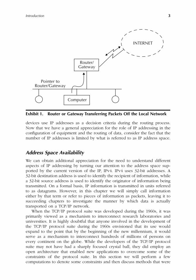
Exhibit 1 illustrates the relationship between a computer located on a localarea network (LAN) that needs to access information on a different networkand a router or gateway that provides a connection between networks. Inexamining Exhibit 1 note that the computer on the LAN is configured with theaddress of the router or gateway. Thus, it knows the location where to transmitinformation destined for outside the confines of the local network. That locationis the address of the router, which in this example routes the data off the localnetwork and into the Internet on its path toward its ultimate destination.
Use of IP Addresses
In examining Exhibit 1 it is important to note that all routing, whether on theInternet or on a private TCP/IP network, occurs using IP addresses. Thus, inaddition to configuring equipment with IP addresses, different networking
AU1144_ch01_fm Page 2 Thursday, October 11, 2001 1:21 PM
Introduction
3
devices use IP addresses as a decision criteria during the routing process.Now that we have a general appreciation for the role of IP addressing in theconfiguration of equipment and the routing of data, consider the fact that thenumber of IP addresses is limited by what is referred to as IP address space.
Address Space Availability
We can obtain additional appreciation for the need to understand differentaspects of IP addressing by turning our attention to the address space sup-ported by the current version of the IP, IPv4. IPv4 uses 32-bit addresses. A32-bit destination address is used to identify the recipient of information, whilea 32-bit source address is used to identify the originator of information beingtransmitted. On a formal basis, IP information is transmitted in units referredto as datagrams. However, in this chapter we will simply call informationeither by that term or refer to pieces of information as packets, leaving it tosucceeding chapters to investigate the manner by which data is actuallytransported on a TCP/IP network.
When the TCP/IP protocol suite was developed during the 1960s, it wasprimarily viewed as a mechanism to interconnect research laboratories anduniversities. It is highly doubtful that anyone involved in the development ofthe TCP/IP protocol suite during the 1960s envisioned that its use wouldexpand to the point that by the beginning of the new millennium, it wouldserve as a mechanism to interconnect hundreds of millions of persons onevery continent on the globe. While the developers of the TCP/IP protocolsuite may not have had a sharply focused crystal ball, they did employ anopen architecture that enabled new applications to overcome some of theconstraints of the protocol suite. In this section we will perform a fewcomputations to denote some constraints and then discuss methods that were
Exhibit 1. Router or Gateway Transferring Packets Off the Local Network
INTERNET
Pointer to
Router/
Computer
Gateway
Router/Gateway
AU1144_ch01_fm Page 3 Thursday, October 11, 2001 1:21 PM
4
The ABCs of IP Addressing
developed to overcome those constraints. In doing so we will become awareof additional reasons why it is necessary for many network managers andLAN administrators to literally move beyond the basics of IP addressing andobtain knowledge of tools and techniques that facilitate the economical useof IP addresses.
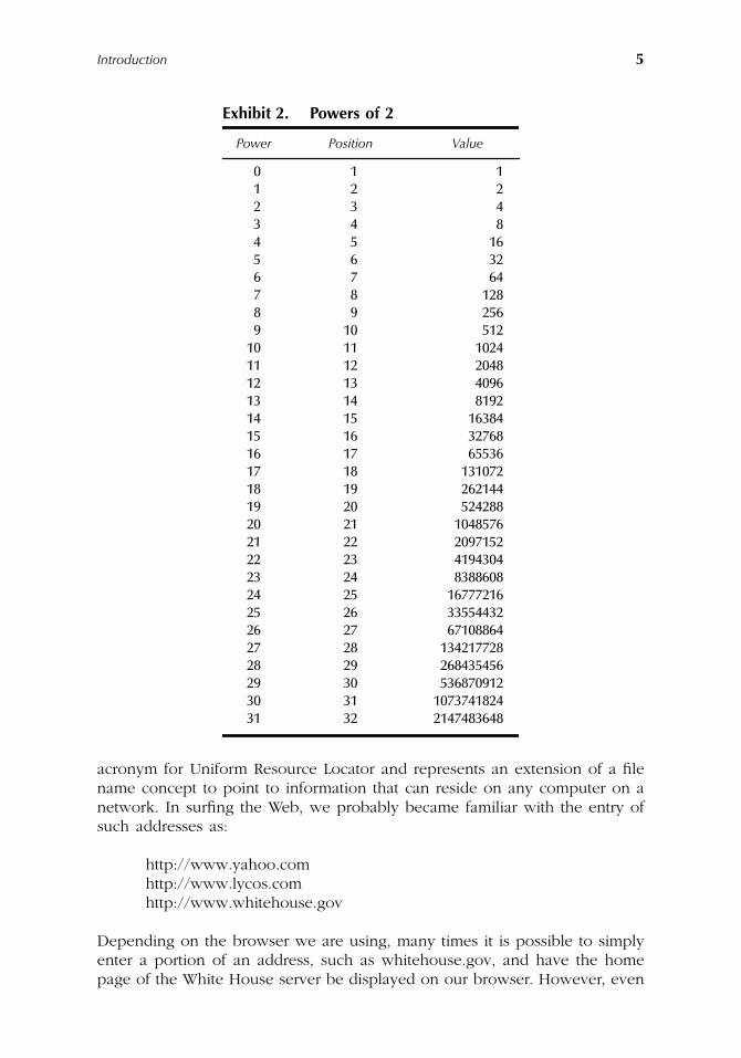
The use of a 32-bit address structure under IPv4 appeared to provide asignificant number of distinct addresses during the 1960s that would enableevery device that required a connection to the Internet to be connected. Ifwe remember the binary number system, which will be reviewed in Chapter 3,each bit position represents a power of two. Exhibit 2 indicates the value ofdifferent powers of 2 from 0 to 31 which represents 32-bit positions used byIPv4 addressing. This table also indicates the bit position of each bit in a32-bit address. Because the 32 bits in an IPv4 address are numbered from 0to 31 to correspond with powers of 2, the position is always 1 above thepower used to compute the value of the position.
In examining the entries in Exhibit 2, note that the value of position nrepresents the sum of all possible values through the power of n – 1. Forexample, when n is 9, the value of position 9 is 256. This represents the rangeof possible values that can be assigned to an 8-bit byte since its value canrange from 0 to 255. Thus, an easy method to determine the theoreticalmaximum number of distinct addresses that could be supported under IPv4would be to simply double the value for position 32 shown in Exhibit 2.Doing so, we obtain a value of 4,294,967,296.
While a value that exceeds four billion was certainly a large value in the1960s, during the past 40 years the proliferation of personal computers, faxmachines, PDAs, mobile phones, and other electronic devices that requireaccess to the Internet has severely taxed the address space of IPv4. Recognizingthe potential shortage of IPv4 addresses resulted in two significant areas ofactivity. One area was focused on developing a new IP protocol that wouldsignificantly expand IP address space. A second area of activity involvedmanaging scarce IPv4 addresses more efficiently. This resulted in the use ofthe Dynamic Host Configuration Protocol (DHCP) and Network AddressTranslation (NAT) as techniques to more efficiently govern the use of IPv4addresses. Thus, for some readers, knowledge of DHCP and NAT will providethe ability to understand how to better manage scarce IPv4 addresses andwill be covered in this book. Now that we have a general appreciation forthe reason why many readers will need to know information beyond basicIPv4 addressing to include applications that manage addresses, let us turn ourattention to how the Internet works. In doing so we will briefly examineURLs, host names, IP addresses, and the role of the DNS to further reinforcethe need for knowledge about a variety of IP addressing techniques.
Internet Operations
If our use of the Internet until now has been one of surfing the Web, ourprimary mechanism for addressing has been the use of URLs. A URL is an
AU1144_ch01_fm Page 4 Thursday, October 11, 2001 1:21 PM
Introduction
5
acronym for Uniform Resource Locator and represents an extension of a filename concept to point to information that can reside on any computer on anetwork. In surfing the Web, we probably became familiar with the entry ofsuch addresses as:
http://www.yahoo.comhttp://www.lycos.comhttp://www.whitehouse.gov
Depending on the browser we are using, many times it is possible to simplyenter a portion of an address, such as whitehouse.gov, and have the homepage of the White House server be displayed on our browser. However, even
Exhibit 2.
Powers of 2
Power Position Value
0 1 11 2 22 3 43 4 84 5 165 6 326 7 647 8 1288 9 2569 10 512
10 11 102411 12 204812 13 409613 14 819214 15 1638415 16 3276816 17 6553617 18 13107218 19 26214419 20 52428820 21 104857621 22 209715222 23 419430423 24 838860824 25 1677721625 26 3355443226 27 6710886427 28 13421772828 29 26843545629 30 53687091230 31 107374182431 32 2147483648
AU1144_ch01_fm Page 5 Thursday, October 11, 2001 1:21 PM
6
The ABCs of IP Addressing
though the ability to use abbreviations expedites productivity, let us take astep back and examine what the preceding addresses in the form of URLsreally mean.
The term
http
stands for Hypertext Transport Protocol. HTTP representsthe protocol used to transport information between Web browsers and Webservers. As part of the format of a URL, the protocol is followed by a colon (:)and two forward slashes (//). Thus, this explains the use of http:// in thepreceding URL.
The information to the right of the pair of forward slashes represents whatis referred to as the fully qualified domain name (FQDN) of the destinationcomputer. That name can be considered to represent a position in an invertedtree structured directory where the suffix (.gov) indicates the address is partof the government domain space. Prefixing the suffix of .gov is .whitehouse,which, when combined with .gov, indicates that the address we seek is theWhite House, which is located in the government domain space. Because theWhite House could have many types of computers, a mechanism is requiredto identify individual computers. That mechanism is obtained by adding ahost computer name to the previous information. Thus, the fully qualifieddomain name becomes www.whitehouse.gov.
When you enter the URL into your browser, several operations will occurtransparently. First, your computer will examine an area of memory referredto as cache memory to determine if the IP address associated with the URLwas previously learned. If so, your browser will use the IP address to createa packet that will request the display of the home page of the White HouseWeb server. If the IP address was not previously learned, it must be determinedbecause all routing is based on IP addresses and not URLs.
When your TCP/IP protocol was installed, another IP address was config-ured that enables the resolution of host names contained in URLs to IPaddresses. That IP address is the location of a Domain Name Server (DNS)that provides a translation capability between host names and IP addresses.The DNS address in effect tells your computer where to go to determine theIP address required to form a packet for routing. Later in this book we willexamine the operation of the DNS; however, for now we only need to knowthat this parallel system enables us to use near-English addresses that areobviously much easier to remember than the composition of a 32-bit desti-nation address.
While many aspects of the DNS are transparent to most users, the ability touse this system requires computers to know the location of at least one DNSserver. Thus, once again it is important to understand IP addressing to includethe configuration of appropriate addresses in various configuration screens.
IPv4 versus IPv6
The protocol we currently use on the Internet is referred to as IPv4. Thisprotocol uses a 32-bit address, which, as previously noted, provides slightlymore than four billion unique addresses. Recognizing that growth in the use
AU1144_ch01_fm Page 6 Thursday, October 11, 2001 1:21 PM
Introduction
7
of the Internet could result in the eventual depletion of IPv4 address space,work commenced on a next generation Internet protocol. Originally referredto as IPng, this protocol was later labeled IPv6.
Under IPv6, an extended addressing scheme is used which results in 128 bitsbeing available for destination and source addresses. Because each bit positiondoubles the number of addresses, it is probably possible for IPv6 to allowevery grain of sand in the Sahara desert to obtain an individual IP address.
Although work was begun on IPv6 many years ago in recognition of theneed to compensate for the rapid depletion of IPv4 address space, the useof DHCP, NAT, subnetting, and other address economizing techniques hasliterally postponed the day of reckoning. Thus, although IPv6 will be coveredin this book, also described and discussed will be address economizingtechniques that may alleviate the necessity to migrate to a new version of IPfor many organizations. However, for other organizations, knowledge of IPv6may be needed sooner rather than later. Thus, once again it becomes obviousthat for many persons it is important to obtain a broad base of knowledgeconcerning IP addressing, including both applications and protocols.
Book Preview
To conclude this chapter, an overview of material to be presented in succeed-ing chapters will be provided. This information can be used either as is or inconjunction with the index to locate information of immediate need. It isrecommended that readers go through the material presented in this book inthe sequence presented. However, it is also recognized that often specificinformation is required and there is not time to sequence through an entirebook to obtain information about a specific topic. Thus, where possible,material in each of the chapters was written to be as independent as possiblefrom preceding and succeeding chapters.
The TCP/IP Protocol Suite
Any book on IP addressing needs to indicate the relationship of the variouscomponents of the TCP/IP protocol suite to IP addresses. Chapter 2 will focuson this topic. In this chapter, we will examine the layered architecture usedby the TCP/IP protocol suite. We will examine both upper and lower layerprotocols, the formation of datagrams, and the manner by which differenttypes of addresses are resolved. Although we will note the location and useof IP addresses, a detailed examination of IPv4 addresses and the role of theDNS will be deferred until Chapter 3.
IPv4 Addressing Basics and the DNS
Because IPv4 represents the current protocol and addressing method used onthe majority of the Internet, we will commence our examination of the
AU1144_ch01_fm Page 7 Thursday, October 11, 2001 1:21 PM
8
The ABCs of IP Addressing
wonderful world of IP addressing with this topic and a related topic. InChapter 3 we will examine the basic structure of IPv4 addresses, how work-stations are configured, and the role of the DNS.
Because readers more than likely have diverse backgrounds, we will initiatea short review of binary mathematics and note the use of dotted decimalnotation in forming an IPv4 address.
The Role of Special IP Addresses
Continuing our probe into IP addressing, we will review the role of specialIP addresses in Chapter 4. Chapter 4 will examine the use of private IPaddresses referred to as RFC 1918 addresses, loopback addresses, and otheraddresses not commonly used on private IP networks as well as on networksconnected to the Internet. The information presented in Chapter 4 will thenbe used to discuss a term referred to as address spoofing by which hackersattempt to hide their true IP address when they attack a host. Because it isdesirable to learn how to block such addresses, we will also turn our attentionto how we can configure a router to provide protection against datagramscontaining commonly spoofed IP addresses from flowing onto our organiza-tion’s network from the Internet.
Subnetting
Subnetting was developed as a mechanism to conserve IP addresses as wellas to reduce router table entries. Chapter 5 will examine how we can designa network consisting of several subnets to include developing an appropriateaddressing scheme. In addition, we will also note the role of the subnet maskand the manner by which participants on a network must be configured tocorrectly operate on a subnet.
CIDR and Multicasting
Chapter 6 will focus on two topics gaining widespread interest among manyorganizations — classless inter-domain routing (CIDR) and multicasting. CIDRprovides organizations with the ability to make more efficient use of IPv4addresses, while multicasting provides organizations with the ability to moreefficiently transmit information destined to multiple users.
NAT and Naming Services
Chapter 7 will focus on two topics that resulted in the ability to significantlyconserve on the use of IPv4 addresses. The topics we will examine includeNetwork Address Translation (NAT), which can permit one IP address to beused to support thousands to tens of thousands of computers accessing theInternet, and two IP naming services that enable IP addresses to be dynamically
AU1144_ch01_fm Page 8 Thursday, October 11, 2001 1:21 PM
Introduction
9
reused. By reading this chapter we will note why we can paraphrase MarkTwain and say that the death of IPv4 is greatly exaggerated.
Working With IPv6
Although the death of Mark Twain might be greatly exaggerated, eventuallythings do come to an end. Eventually the last IPv4 address will be allocatedand the Internet community will have to migrate to IPv6, which is the focusof Chapter 8. Chapter 8 will examine the structure of IPv6, its enhancedaddressing capability, and the improvements provided by the protocol whichextend beyond an increased addressing capability.
Network Utility Tools
In concluding this book we will turn our attention to the use of a core setof network utility tools that facilitate the testing and troubleshooting of TCP/IP networks. Chapter 9 will examine the old workhorses known as Ping andTraceroute as well as the more modern Pingpath introduced under Windows2000. Therefore, if you are still sipping a Coke or Pepsi, relax a momentand follow me to the next chapter to obtain an appreciation of the TCP/IPprotocol suite.
AU1144_ch01_fm Page 9 Thursday, October 11, 2001 1:21 PM

AU1144_ch01_fm Page 10 Thursday, October 11, 2001 1:21 PM
11
Chapter 2
The TCP/IP Protocol Suite
The primary purpose of Chapter 2 is to obtain an appreciation for the generalcomposition of the TCP/IP protocol suite. To accomplish this task, we willfirst examine the International Standards Organization (ISO) Open SystemsInterconnection (OSI) Reference Model. Once this is accomplished, we willexamine the Internet Protocol (IP), which represents a network layer protocol.This will be followed by moving up the protocol stack and examiningoperations at the transport layer.
The OSI Reference Model
Although the TCP/IP protocol suite predated the OSI Reference Model, wecan obtain a better appreciation for the functioning of the TCP/IP protocolsuite by examining the layering concept associated with communicationsdefined by that model. During the 1970s, approximately a dozen years afterthe development of several popular communications protocols to include TCP/IP, the International Standards Organization (ISO) established a framework forstandardizing communications systems. This framework was called the OpenSystem Interconnection (OSI) Reference Model and it defines an architecturein which communications functions are divided into seven distinct layers, withspecific functions becoming the responsibility of a particular layer.
Exhibit 1 illustrates the seven layers of the OSI Reference Model. Note thateach layer, with the exception of the lowest, covers a lower layer, effectivelyisolating it from higher layer functions. Layer isolation is an important aspectof the OSI Reference Model because it allows the given characteristics of onelayer to change without affecting the remainder of the model, provided thatsupport services remain the same. This is possible because well-known inter-face points in a layered model enable one layer to communicate with another,even though one or both may change. In addition, the layering process permits
AU1144_ch02_fm Page 11 Thursday, October 11, 2001 1:22 PM
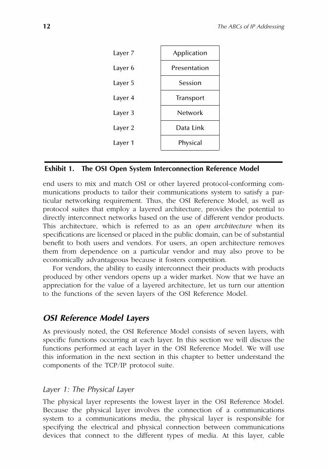
12
The ABCs of IP Addressing
end users to mix and match OSI or other layered protocol-conforming com-munications products to tailor their communications system to satisfy a par-ticular networking requirement. Thus, the OSI Reference Model, as well asprotocol suites that employ a layered architecture, provides the potential todirectly interconnect networks based on the use of different vendor products.This architecture, which is referred to as an
open architecture
when itsspecifications are licensed or placed in the public domain, can be of substantialbenefit to both users and vendors. For users, an open architecture removesthem from dependence on a particular vendor and may also prove to beeconomically advantageous because it fosters competition.
For vendors, the ability to easily interconnect their products with productsproduced by other vendors opens up a wider market. Now that we have anappreciation for the value of a layered architecture, let us turn our attentionto the functions of the seven layers of the OSI Reference Model.
OSI Reference Model Layers
As previously noted, the OSI Reference Model consists of seven layers, withspecific functions occurring at each layer. In this section we will discuss thefunctions performed at each layer in the OSI Reference Model. We will usethis information in the next section in this chapter to better understand thecomponents of the TCP/IP protocol suite.
Layer 1: The Physical Layer
The physical layer represents the lowest layer in the OSI Reference Model.Because the physical layer involves the connection of a communicationssystem to a communications media, the physical layer is responsible forspecifying the electrical and physical connection between communicationsdevices that connect to the different types of media. At this layer, cable
Layer 7 Application
Layer 6 Presentation
Layer 5 Session
Layer 4 Transport
Layer 3 Network
Layer 2 Data Link
Layer 1 Physical
Exhibit 1. The OSI Open System Interconnection Reference Model
AU1144_ch02_fm Page 12 Thursday, October 11, 2001 1:22 PM
The TCP/IP Protocol Suite
13
connections and the electrical rules necessary to transfer data between devicesare specified. Examples of physical layer standards include RS-232, V.24, andthe V.35 interface.
Layer 2: The Data Link Layer
The second layer in the OSI Reference Model is the data link layer. This layeris responsible for defining the manner by which a device gains access to themedium specified in the physical layer. In addition, the data link layer is alsoresponsible for defining data formats to include the entity by which informationis transported, error control procedures, and other link control procedures.
Most trade literature and other publications reference the entity by whichinformation is transported at the data link layer as a frame. Depending on theprotocol used, the frame will have a certain header composition with fieldsthat normally indicate the destination address and the originator of the framethrough the use of a source address. In addition, frames will have a trailerwith a cyclic redundancy check (CRC) field that indicates the value of an errorchecking mechanism algorithm performed by the originator on the contentsof the frame. The receiver will apply the same algorithm to an inbound frameand compare the locally generated CRC to the CRC in the trailer. If the twomatch, the frame is considered to be received without error, while a mismatchindicates a transmission error occurred, and the receiver will then request theoriginator to retransmit the frame. Examples for common Layer 2 protocolsinclude such LAN protocols as Ethernet and Token-Ring as well as such WANprotocols as High-Level Data Link Control (HDLC).
The original development of the OSI Reference Model targeted wide areanetworking. This resulted in its applicability to LANs requiring a degree ofmodification. The Institute of Electrical and Electronic Engineers (IEEE), whichis responsible for developing LAN standards, subdivided the data link layerinto two sublayers: (1) Logical Link Control (LLC) and (2) Media Access Control(MAC). The LLC layer is responsible for generating and interpreting commandsthat control the flow of data and performing recovery operations in the eventerrors are detected. In comparison, the MAC layer is responsible for providingaccess to the local area network, which enables a station on the network totransmit information. The subdivision of the data link layer allows a commonLLC layer to be used regardless of differences in the method of network access.Thus, a common LLC is used for both Ethernet and Token-Ring although theiraccess methods are dissimilar.
Layer 3: The Network Layer
Moving up the OSI Reference Model, the third layer is the network layer. Thislayer is responsible for arranging a logical connection between a source anddestination on the network to include the selection and management of aroute for the flow of information between source and destination based onthe available paths within a network.
AU1144_ch02_fm Page 13 Thursday, October 11, 2001 1:22 PM
14
The ABCs of IP Addressing
Services or functions provided at the network layer are associated withthe movement of data through a network to include addressing, routing,switching, sequencing, and flow control procedures. At the network layer,units of information are placed into packets that have a header and trailersimilar to frames at the data link layer. Thus, the network layer packet willcontain addressing information as well as a field that facilitates error detectionand correction.
In a complex network, the source and destination may not be directlyconnected by a single path. Instead, a path may be required to be establishedthrough the network that consists of several subpaths. Thus, the routing ofpackets through the network as well as the mechanism in the form of routingprotocols that provide information about available paths are important featuresof this layer.
Several protocols are standardized for Layer 3 to include the InternationalTelecommunications Union Telecommunications body (ITU-T) X.25 packetswitching protocol and the ITU-TX75 gateway protocol. X.25 governs the flowof information through packet network, whereas X.75 governs the flow ofinformation between packet networks. When we examine the TCP/IP protocolsuite in succeeding sections in this chapter, note that the IP represents thenetwork layer protocol used in the TCP/IP protocol suite.
Layer 4: The Transport Layer
Continuing our tour of the OSI Reference Model, the transport layer isresponsible for governing the transfer of information after a route has beenestablished through the network by the network layer protocol. There aretwo general types of transport layer protocols: (1) connection-oriented and(2) connectionless. A connection-oriented protocol first requires the establish-ment of a connection prior to data transfer occurring. This type of transportlayer protocol performs error control, sequence checking, and other end-to-end data reliability functions. A second type or category of transport layerprotocol operates as a connectionless, best-effort protocol. This type of pro-tocol depends on higher layers in the protocol suite for error detection andcorrection. As we examine the TCP/IP protocol suite, we will note that TCPrepresents a Layer 4 connection-oriented protocol while UDP represents aconnectionless Layer 4 protocol.
Layer 5: The Session Layer
The fifth layer in the OSI Reference Model is the session layer. This layer isresponsible for providing a set of rules that govern the establishment andtermination of data streams flowing between nodes in a network. The servicesthat the session layer can provide include establishing and terminating node
AU1144_ch02_fm Page 14 Thursday, October 11, 2001 1:22 PM
The TCP/IP Protocol Suite
15
connections, message flow control, dialogue control, and end-to-end datacontrol. In the TCP/IP protocol suite, Layers 5 through 7 are grouped togetheras an application layer.
Layer 6: The Presentation Layer
The sixth layer of the OSI Reference Model is the presentation layer. Thislayer is concerned with the conversion of transmitted data into a displayformat appropriate for a receiving device. This conversion can include datacodes as well as display placement. Other functions performed at the pre-sentation layer can include data compression and decompression and dataencryption and decryption.
Layer 7: The Application Layer
The top layer of the OSI Reference Model is the application layer. This layerfunctions as a window through which the application gains access to all ofthe services provided by the model. Examples of functions performed at theapplication layer include electronic mail, file transfers, resource sharing, anddata base access. Although the first four layers of the OSI Reference Modelare fairly well defined, the top three layers can vary considerably betweennetworks. As previously mentioned, the TCP/IP protocol suite, which is alayered protocol that predates the ISO Reference Model, combines Layers 5through 7 into one application layer.
Data Flow
The design of an OSI Reference Model compatible network is such that aseries of headers are opened to each data unit as packets are transmitted anddelivered by frames. At the receiver, the headers are removed as a data unitflows up the protocol suite, until the
headerless
data unit is identical to thetransmitted data unit. In the next section of this chapter, we will examine theflow of data in a TCP/IP network that follows the previously described OSIReference Model data flow.
The OSI Reference Model never lived up to its intended goal, with ISOprotocols achieving a less than anticipated level of utilization. The conceptsof the model made persons aware of the benefits that could be obtained bya layered open architecture as well as the functions that would be performedby different layers of the model. Thus, the ISO succeeded in making network-ing personnel aware of the benefits that could be derived from a layered openarchitecture and more than likely contributed to the success of the acceptanceof the TCP/IP protocol suite. We will now turn our attention to the TCP/IPprotocol suite.
AU1144_ch02_fm Page 15 Thursday, October 11, 2001 1:22 PM

16
The ABCs of IP Addressing
Overview of the TCP/IP Protocol Suite
The Transmission Control Protocol/Internet Protocol (TCP/IP) actually repre-sents two distinct protocols within the TCP/IP protocol suite. Due to thepopularity of those protocols, and the fact that a majority of traffic is transferredusing those protocols, the members of the protocol suite include TCP and IPand are collectively referred to as TCP/IP.
Exhibit 2 provides a general comparison of the structure of the TCP/IPprotocol suite to the OSI Reference Model. The term
general comparison
isused because the protocol suite consists of hundreds of applications, of whichonly a handful is shown. Another reason that Exhibit 2 is a general comparisonresults from the fact that the TCP/IP protocol suite actually begins above thedata link layer. Although the physical and data link layers are not part of theTCP/IP protocol suite, they are shown in Exhibit 2 to provide a frame ofreference to the OSI Reference Model as well as to facilitate an explanationof the role of two special protocols within the TCP/IP protocol suite.
The Network Layer
The network layer of the TCP/IP protocol stack primarily consists of the IP.The IP protocol includes an addressing scheme that identifies the source anddestination address of the packet being transported. In TCP/IP terminology,the unit of data being transmitted at the network layer is referred to as adatagram. Also included in what can be considered to represent the networkprotocols are the address resolution protocol (ARP) and the Internet ControlMessage Protocol (ICMP).
OSI Reference TCP/IP Protocol SuiteModel Layer
Application
FTP HTTP Telnet SMTP DNS SNMPOther
ApplicationsPresentation
Session
Transport TCP UDP
Network
ICMP
IP
ARP
Data Link Ethernet Token Ring X.25 Frame Relay Other
Physical Physical Layer
Exhibit 2. Comparing the TCP/IP Protocol Suite to the OSI Reference Model
AU1144_ch02_fm Page 16 Thursday, October 11, 2001 1:22 PM
The TCP/IP Protocol Suite
17
IP
The IP provides the addressing capability that allows datagrams to be routedbetween networks. The current version of IP is IPv4, under which IP addressesconsist of 32 bits. There are currently five classes of IP addresses, referred toas Class A through Class E, with Classes A, B, and C having their 32 bitssubdivided into a network portion and a host portion. The network portionof the address defines the network where a particular host resides, while thehost portion of the address identifies a unique host on the network. Later inthis chapter we will examine the IP in detail. However, we will defer untilChapter 3 a detailed examination of IP addressing.
ARP
One of the more significant differences between the data link layer and thenetwork layer is the method of addressing used at each layer. At the data linklayer, such LANs as Ethernet and Token-Ring networks use 48-bit MACaddresses. In comparison, TCP/IP currently uses 32-bit addresses under thecurrent version of the IPD protocol, and the next generation of the IP protocol,IPv6, uses a 128-bit address. Thus, the delivery of a packet or datagram flowingat the network layer to a station on the LAN requires an address conversion.That address conversion is performed by the Address Resolution Protocolwhose operation is covered in detail later in this chapter.
ICMP
The Internet Control Message Protocol (ICMP), as its name implies, representsa protocol used to convey control messages. Such messages range in scopefrom routers responding to a request that cannot be honored with a
destinationunreachable
message to the requester, to messages that convey diagnostictests and responses. An example of the latter is the echo-request/echo-responsepair of ICMP datagrams that is more popularly referred to collectively as Ping.
ICMP messages are conveyed with the prefix of an IP headed to themessage. Thus, we can consider ICMP to represent a Layer 3 protocol in theTCP/IP protocol suite. We will examine the structure of ICMP messages aswell as the use of certain messages later in this chapter when we examinethe network layer of the TCP/IP protocol suite detail.
The Transport Layer
As indicated in Exhibit 2, there are two transport layer protocols supportedby the TCP/IP protocol suite: (1) the Transmission Control Protocol (TCP) and(2) the User Datagram Protocol (UDP).
AU1144_ch02_fm Page 17 Thursday, October 11, 2001 1:22 PM
18
The ABCs of IP Addressing
TCP
TCP (Transmission Control Protocol) is an error-free, connection-orientedprotocol. This means that prior to data being transmitted by TCP, the protocolrequires the establishment of a path between source and destination as wellas an acknowledgment that the receiver is ready to receive information. Oncethe flow of data commences, each unit, which is referred to as a TCP segment,is checked for errors at the receiver. If an error is detected through a checksumprocess, the receiver will request the originator to retransmit the segment.Thus, TCP represents an error-free, connection-oriented protocol.
The advantages associated with the use of TCP as a transport protocolrelate to its error-free, connection-oriented functionality. For the transmissionof relatively large quantities of data or important information, it makes senseto use this transport layer protocol. The connection-oriented feature of theprotocol means that it will require a period of time for the source anddestination to exchange handshake information. In addition, the error-freecapability of the protocol may be redundant if the higher layer in the protocolsuite also performs error checking. Recognizing the previously mentionedproblems, the developers of the TCP/IP protocol suite added a second trans-port layer protocol referred to as UDP.
UDP
The User Datagram Protocol (UDP) is a connectionless, best-effort, non-errorchecking transport protocol. UDP was developed in recognition of the factthat some applications may require small pieces of information to be trans-ferred, and the use of a connection-oriented protocol would result in asignificant overhead to the transfer of data. Because a higher layer in theprotocol suite could perform error checking, error detection and correctioncould also be eliminated from UDP. Because UDP transmits a piece ofinformation referred to as a UDP datagram without first establishing a con-nection to the receiver, the protocol is also referred to as a
best-effort
protocol.To ensure that a series of UDP datagrams are not transmitted into a blackhole if a receiver is not available, the higher layer in the protocol suite usingUDP as a transport protocol will wait for an acknowledgment. If one is notreceived within a predefined period of time, the application can decidewhether to retransmit or cancel the session.
In examining Exhibit 2 you will note that certain applications use TCP astheir transport protocol while other applications use UDP. In general, appli-cations that require data integrity, such as remote terminal transmission (Tel-net), file transfer (FTP), and electronic mail, use TCP as their transport protocol.In comparison, applications that transmit relatively short packets, such as theDomain Name Service (DNS) and the Simple Network Management Protocol(SNMP) that is used to perform network management operations, use UDP.
One relatively new TCP/IP application takes advantage of both the TCPand UDP transport protocols. That application is voice over IP (VoIP). VoIPcommonly uses TCP to set up a call and convey signaling information to the
AU1144_ch02_fm Page 18 Thursday, October 11, 2001 1:22 PM
The TCP/IP Protocol Suite
19
distant party. Because real time voice cannot be delayed by retransmission ifan error in a packet is detected, there is no need to perform error detection.Thus, digitized voice samples are commonly transmitted using UDP once asession is established using TCP.
Application Layer
As previously noted, the development of the TCP/IP protocol suite predatedthe development of the ISO’s OSI Reference Model. At the time the TCP/IPprotocol suite was developed, functions above the transport layer were com-bined into one entity that represented an application. Thus, the TCP/IPprotocol suite does not include separate session and presentation layers. Nowthat we have an appreciation for the manner by which the TCP/IP protocolstack can be compared and contrasted to the OSI Reference Model, we willconclude this section by examining the flow of data within a TCP/IP network.
Data Flow
Data flow within a TCP/IP network commences at the application layerwhere data is provided to an applicable transport layer protocol-TCP orUDP. At Layer 4, the transport layer opens either a TCP or a UDP headerto the application data depending on the transport protocol used by theapplication layer.
The transport layer protocol uses a port number to distinguish the type ofapplication data being transported. Through the use of port numbers, itbecomes possible to distinguish one application from another that flowsbetween a common source and destination.
For lay persons not familiar with TCP or IP, this explains how a commonhardware platform, such as a Windows NT server, can support both Web andFTP services. That is, although the server has a common IP address containedin an IP header, the port number in the TCP or UDP header indicates theapplication.
Application data flowing onto a network is first formed into a TCP segmentor UDP datagram. The resulting UDP datagram or TCP segment is then passedto the network layer where an IP header is opened. The IP header containsnetwork addressing information that is used by routers to route datagramsthrough a network.
When an IP datagram reaches a LAN, the difference between the networklayer and LAN address is first resolved through ARP. Once this is accomplished,the IP datagram is placed into a LAN frame using an appropriate MAC addressin the LAN header. Exhibit 3 illustrates the data flow within a TCP/IP networkfor deliver to a station on a LAN.
The TCP/IP protocol suite represents a methodically considered and devel-oped collection of protocols and applications. As we will note in subsequentsections of this chapter, it is a very flexible open architecture that allows newapplications and protocols to be developed.
AU1144_ch02_fm Page 19 Thursday, October 11, 2001 1:22 PM
20
The ABCs of IP Addressing
The Internet Protocol and Related Protocols
In this section attention will focus on what this author commonly refers to asthe Network Layer Troika of the TCP/IP protocol suite, IP, ARP, and ICMP. Inexamining the IP, we will pay particular attention to the structure of the IPheader and its fields, which are examined by routers as a mechanism formaking forwarding decisions. Although we will defer a detailed discussion ofIP addressing until Chapter 4, we will discuss several little known areas ofthe IP protocol. Having knowledge about these areas can provide us withnetwork design and operation flexibility. One such topic is the assignment ofmultiple network addresses to an interface.
Initial focus in this section is on the IP protocol to include its use forrouting datagrams across a network and between interconnected networks.In doing so, we will examine in detail the composition of the IP header andthe use of different fields in the header. Once this is accomplished, attentionwill be on the role and operation of the Address Resolution Protocol (ARP)to include examining the rationale for a little-known ARP technique that canconsiderably facilitate the operation of delay sensitive transmissions, such asvoice over IP. This section will conclude with Internet Control MessageProtocol (ICMP).
The Internet Protocol
The IP represents the network layer of the TCP/IP protocol suite. IP wasdeveloped as a mechanism to interconnect packet switched TCP/IP basednetworks to form an internet. Here the term
internet
with a lower case
i
isused to represent the connection of two or more TCP/IP based networks.
Datagrams and Segments
The IP transmits blocks of data referred to as datagrams. As indicated inExhibit 3, IP receives upper layer protocol data containing either a TCP orUDP header, referred to as a TCP segment or UDP datagram. The prefix ofan IP header to the TCP segment or UDP datagram results in the formationof an IP datagram. This datagram contains a destination IP address that isused for routing purposes.
Datagrams and Datagram Transmissions
To alleviate potential confusion between datagrams and an obsolete transmis-sion method referred to as datagram transmission, a few words are in order.When the ARPAnet evolved, two methods of packet transmission were exper-imented with. One method was referred to as datagram transmission andavoided the use of routers to perform table lookups. Under datagram trans-mission, each node in a network transmits a received datagram onto all portsother than the port the datagram was received on. While this technique avoidsthe need for routing table lookup operations, it can result in duplicate
AU1144_ch02_fm Page 20 Thursday, October 11, 2001 1:22 PM
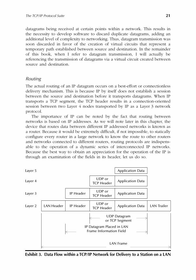
The TCP/IP Protocol Suite
21
datagrams being received at certain points within a network. This results inthe necessity to develop software to discard duplicate datagrams, adding anadditional level of complexity to networking. Thus, datagram transmission wassoon discarded in favor of the creation of virtual circuits that represent atemporary path established between source and destination. In the remainderof this book, when I refer to datagram transmission, I will actually bereferencing the transmission of datagrams via a virtual circuit created betweensource and destination.
Routing
The actual routing of an IP datagram occurs on a best-effort or connectionlessdelivery mechanism. This is because IP by itself does not establish a sessionbetween the source and destination before it transports datagrams. When IPtransports a TCP segment, the TCP header results in a connection-orientedsession between two Layer 4 nodes transported by IP as a Layer 3 networkprotocol.
The importance of IP can be noted by the fact that routing betweennetworks is based on IP addresses. As we will note later in this chapter, thedevice that routes data between different IP addressed networks is known asa router. Because it would be extremely difficult, if not impossible, to staticallyconfigure every router in a large network to know the route to other routersand networks connected to different routers, routing protocols are indispens-able to the operation of a dynamic series of interconnected IP networks.Because the best way to obtain an appreciation for the operation of the IP isthrough an examination of the fields in its header, let us do so.
Layer 5 Application Data
Layer 4UDP or
TCP HeaderApplication Data
Layer 3 IP HeaderUDP or
TCP HeaderApplication Data
Layer 2 LAN Header IP HeaderUDP or
TCP HeaderApplication Data LAN Trailer
UDP Datagramor TCP Segment
IP Datagram Placed in LANFrame Information Field
LAN Frame
Exhibit 3. Data Flow within a TCP/IP Network for Delivery to a Station on a LAN
AU1144_ch02_fm Page 21 Thursday, October 11, 2001 1:22 PM
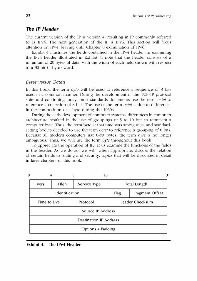
22
The ABCs of IP Addressing
The IP Header
The current version of the IP is version 4, resulting in IP commonly referredto as IPv4. The next generation of the IP is IPv6. This section will focusattention on IPv4, leaving until Chapter 8 examination of IPv6.
Exhibit 4 illustrates the fields contained in the IPv4 header. In examiningthe IPv4 header illustrated in Exhibit 4, note that the header consists of aminimum of 20 bytes of data, with the width of each field shown with respectto a 32-bit (4-byte) word.
Bytes versus Octets
In this book, the term
byte
will be used to reference a sequence of 8 bitsused in a common manner. During the development of the TCP/IP protocolsuite and continuing today, most standards documents use the term
octet
toreference a collection of 8 bits. The use of the term
octet
is due to differencesin the composition of a byte during the 1960s.
During the early development of computer systems, differences in computerarchitecture resulted in the use of groupings of 5 to 10 bits to represent acomputer byte. Thus, the term byte at that time was ambiguous, and standard-setting bodies decided to use the term
octet
to reference a grouping of 8 bits.Because all modern computers use 8-bit bytes, the term
byte
is no longerambiguous. Thus, we will use the term
byte
throughout this book.To appreciate the operation of IP, let us examine the functions of the fields
in the header. As we do so, we will, when appropriate, discuss the relationof certain fields to routing and security, topics that will be discussed in detailin later chapters of this book.
0 4 8 16 31
Vers Hlen Service Type Total Length
Identification Flag Fragment Offset
Time to Live Protocol Header Checksum
Source IP Address
Destination IP Address
Options + Padding
Exhibit 4. The IPv4 Header
AU1144_ch02_fm Page 22 Thursday, October 11, 2001 1:22 PM
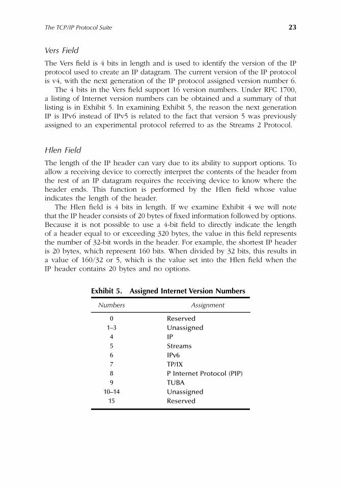
The TCP/IP Protocol Suite
23
Vers Field
The Vers field is 4 bits in length and is used to identify the version of the IPprotocol used to create an IP datagram. The current version of the IP protocolis v4, with the next generation of the IP protocol assigned version number 6.
The 4 bits in the Vers field support 16 version numbers. Under RFC 1700,a listing of Internet version numbers can be obtained and a summary of thatlisting is in Exhibit 5. In examining Exhibit 5, the reason the next generationIP is IPv6 instead of IPv5 is related to the fact that version 5 was previouslyassigned to an experimental protocol referred to as the Streams 2 Protocol.
Hlen Field
The length of the IP header can vary due to its ability to support options. Toallow a receiving device to correctly interpret the contents of the header fromthe rest of an IP datagram requires the receiving device to know where theheader ends. This function is performed by the Hlen field whose valueindicates the length of the header.
The Hlen field is 4 bits in length. If we examine Exhibit 4 we will notethat the IP header consists of 20 bytes of fixed information followed by options.Because it is not possible to use a 4-bit field to directly indicate the lengthof a header equal to or exceeding 320 bytes, the value in this field representsthe number of 32-bit words in the header. For example, the shortest IP headeris 20 bytes, which represent 160 bits. When divided by 32 bits, this results ina value of 160/32 or 5, which is the value set into the Hlen field when theIP header contains 20 bytes and no options.
Exhibit 5. Assigned Internet Version Numbers
Numbers Assignment
0 Reserved1–3 Unassigned4 IP5 Streams6 IPv67 TP/IX8 P Internet Protocol (PIP)9 TUBA
10–14 Unassigned15 Reserved
AU1144_ch02_fm Page 23 Thursday, October 11, 2001 1:22 PM
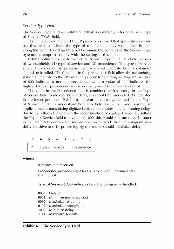
24
The ABCs of IP Addressing
Service Type Field
The Service Type field is an 8-bit field that is commonly referred to as a Typeof Service (TOS) field.
The initial development of the IP protocol assumed that applications woulduse this field to indicate the type of routing path they would like. Routersalong the path of a datagram would examine the contents of the Service Typebyte and attempt to comply with the setting in this field.
Exhibit 6 illustrates the format of the Service Type field. This field consistsof two subfields: (1) type of service and (2) precedence. The type of servicesubfield consists of bit positions that, when set, indicate how a datagramshould be handled. The three bits in the precedence field allow the transmittingstation to indicate to the IP layer the priority for sending a datagram. A valueof 000 indicates a normal precedence, while a value of 111 indicates thehighest level of precedence and is normally used for network control.
The value in the Precedence field is combined with a setting in the Typeof Service field to indicate how a datagram should be processed. As indicatedin the lower portion of Exhibit 6, there are six settings defined for the Typeof Service field. To understand how this field would be used, assume anapplication was transmitting digitized voice that requires minimal routing delaysdue to the effect of latency on the reconstruction of digitized voice. By settingthe Type of Service field to a value of 1000, this would indicate to each routerin the path between source and destination network that the datagram wasdelay sensitive and its processing by the router should minimize delay.
7 6 5 4 3 2 1 0
R Type of Service Precedence
where:
R represents reserved.
Precedence provides eight levels, 0 to 7, with 0 normal and 7 the highest.
Type of Service (TOS) indicates how the datagram is handled.
0000 Default0001 Minimize monetary cost0010 Maximize reliability0100 Maximize throughput1000 Minimize delay1111 Maximize security
Exhibit 6. The Service Type Field
AU1144_ch02_fm Page 24 Thursday, October 11, 2001 1:22 PM
The TCP/IP Protocol Suite
25
In comparison, because routers are designed to discard packets underperiods of congestion, an application where the ability of packets to reachtheir destination is of primary importance would set the TOS field to a valueof 0010. This setting would denote to routers in the transmission path thatthe datagram requires maximum reliability. Thus, routers would select otherpackets for discard prior to discarding a packet with its TOS subfield set toa value of 0010.
Although the concept behind including a Service Type field was a goodidea, from a practical standpoint it is rarely used. The reason for its lack ofuse is the need for routers supporting this field to construct and maintainmultiple routing tables. While this is not a problem for small networks, thecreation and support of multiple routing tables can significantly effect thelevel of performance of routers in a complex network, such as the Internet.
Although routers in most networks ignore the contents of the Service Typefield, this field is now being used to map IP datagrams being transmitted overan ATM backbone. Because ATM includes a built-in Quality of Service (QOS)that, at the present time, cannot be obtained on an IP network, manyorganizations are transmitting a variety of data to include voice over IP overan ATM backbone, using the Service Type field as a mechanism to mapdifferent IP service requirements into applicable types of ATM service. Asecond emerging application for the Service Type field is to differentiate therequirements of different applications as they flow into an IP network. In thissituation, the Service Type byte is renamed as the DiffServe (DifferentiatedService) byte. The Internet Engineering Task Force is currently examining thepotential use of the DiffServe byte as a mechanism to define an end-to-endquality of service capability through an IP network.
Total Length Field
The Total Length field indicates the total length of an IP datagram in bytes.This length indicates the length of the IP header to include options followedby a TCP or UDP header or another type of header that we will shortly discuss,as well as the data that follows that header. The total length field is 16 bitsin length, resulting in an IP datagram having a maximum defined length of2
16
or 65536 bytes.
Identification and Fragment Offset Fields
Unlike some types of clothing where one size fits all, an IP datagram canrange up to 65536 bytes in length. Because some networks only support atransport frame that can carry a small portion of the theoretical maximumlength IP datagram, it can become necessary to fragment the datagram fortransmission between networks. One example of this would be the routingof a datagram from a Token-Ring network to another Token-Ring network via
AU1144_ch02_fm Page 25 Thursday, October 11, 2001 1:22 PM
26
The ABCs of IP Addressing
an Ethernet network. Token-Ring networks that operate at 16 Mbps cantransport approximately 18 Kbytes in their Information field. In comparison,an Ethernet frame has a maximum length Information field of 1500 bytes. Thismeans that datagrams routed between Token-Ring networks via an Ethernetnetwork must be subdivided or fragmented into a maximum length of 1500bytes for Ethernet to be able to transport the data.
The default IP datagram length is referred to as the path MTU (MaximumTransmission Unit). The MTU is defined as the size of the largest packet thatcan be transmitted or received through a logical interface. When two Token-Ring networks are connected via an Ethernet network, the MTU would be1500 bytes. Because it is important to commence transmission with the lowestcommon denominator packet size that can flow through different networks,and, if possible, adjust the packet size after the initial packet reaches itsdestination, IP datagrams use a default of 576 bytes when datagrams aretransmitted remotely (off the current network).
Fragmentation is a most interesting function because it allows networkscapable of transmitting larger packets to do so more efficiently. The reasonefficiency increases is due to the fact that larger packets have proportionallyless overhead. Unfortunately, the gain in packet efficiency is not without cost.First, although routers can fragment datagrams, they do not reassemble them,leaving it to the host to perform reassembly. This is because router CPU andmemory requirements would considerably expand if they had to reassembledatagrams flowing to networks containing hundreds or thousands of hosts.Secondly, although fragmentation is a good idea for boosting transmissionefficiency, a setting in the Flag field, which we will shortly cover, can be usedto indicate a datagram should not be fragmented. Because many routers donot support fragmentation, many applications by default set the do notfragment flag bit and use a datagram length that, while perhaps not mostefficient, ensures that a datagram can flow end-to-end as its length representsthe lowest common denominator of the networks it will traverse.
When an IP datagram is fragmented, this situation results in the use ofthree fields in the IP header. Those fields are the Identification, Flag, andFragment Offset fields.
The Identification field is 16 bytes in length and is used to indicate whichdatagram fragments belong together. A receiving device operation at the IPnetwork layer uses the Identification field as well as the source IP address todetermine which fragments belong together. To ensure fragments are put backtogether in their appropriate order requires a mechanism to distinguish onefragment from another. That mechanism is provided by the Fragment Offsetfield, which indicates the location where each fragment belongs in a completemessage. The actual value in the Fragment Offset field is an integer thatcorresponds to a unit of 8 bytes that indicates the offset from the previousdatagram. For example, if the first fragment were 512 bytes in length, thesecond fragment would have an offset value that indicates that this IP datagramcommences at byte 513. By using the total length and Fragment Offset fields,a receiver can easily reconstruct a fragmented datagram.
AU1144_ch02_fm Page 26 Thursday, October 11, 2001 1:22 PM
The TCP/IP Protocol Suite
27
Flag Field
The third field in the IP header directly associated with fragmentation is theFlag field. This field is 4 bytes in length, with 2 bits used to denote fragmen-tation information. The setting of one of those bits is used as a direct fragmentcontrol mechanism, since a value of
0
indicates the datagram can be frag-mented, while a value of
1
indicates do not fragment the datagram. Thesecond fragment bit is used to indicate fragmentation progress. When thesecond bit is set to a value of
0
, it indicates that the current fragment in adatagram is the last fragment. In comparison, a value of
1
in this bit positionindicates that more fragments follow.
Time to Live Field
The Time to Live (TTL) field is 8 bits in length. The setting in this field isused to specify the maximum amount of time that a datagram can exist. It isused to prevent a misaddressed datagram from endlessly wandering theInternet or a private IP network, similar to the manner by which a famousAmerican folk hero was noted in a song to wander the streets of Boston.
Because an exact time is difficult to measure, the value placed into theTTL field is actually a router hop count. That is, routers decrement the valueof the TTL field by 1 as a datagram flows between networks. If the value ofthis field reaches zero, the router will discard the datagram and, dependingon the configuration of the router, generate an ICMP message that informsthe originator of the datagram that the TTL field expired and the datagram,in effect, was sent to the great bit bucket in the sky.
Many applications set the TTL field value to a default of 32, which shouldbe more than sufficient to reach most destinations in a very complex networkto include the Internet. In fact, one popular application referred to as Trace-route will issue a sequence of datagrams commencing with a value of 1 inthe TTL field to obtain a sequence of router-generated ICMP messages thatenable the path from source to destination to be noted. Chapter 9 will examinethe operation of the Traceroute application and note how it can be used asa diagnostic tool.
Protocol Field
In Exhibit 3, we noted that an IP header prefixes the transport layer headerto form an IP datagram. While TCP and UDP represent a large majority ofLayer 4 protocols carried in an IP datagram, they are not the only protocolstransported. In addition, even if they were, we would need a mechanism todistinguish one upper layer protocol from another that is carried in a datagram.
The method used to distinguish the upper layer protocol carried in an IPdatagram is obtained through the use of a value in the Protocol field. Forexample, a value of decimal 6 is used to indicate that a TCP header followsthe IP header, while a value of decimal 17 indicates that a UDP header followsthe IP header in a datagram.
AU1144_ch02_fm Page 27 Thursday, October 11, 2001 1:22 PM
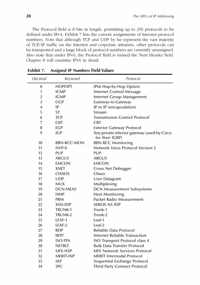
28
The ABCs of IP Addressing
The Protocol field is 8 bits in length, permitting up to 256 protocols to bedefined under IPv4. Exhibit 7 lists the current assignments of Internet protocolnumbers. Note that although TCP and UDP by far represent the vast majorityof TCP/IP traffic on the Internet and corporate intranets, other protocols canbe transported and a large block of protocol numbers are currently unassigned.Also note that under IPv6, the Protocol field is named the Next Header field.Chapter 8 will examine IPv6 in detail.
Exhibit 7. Assigned IP Numbers Field Values
Decimal Keyword Protocol
0 HOPOPT IPv6 Hop-by-Hop Option1 ICMP Internet Control Message2 IGMP Internet Group Management3 GGP Gateway-to-Gateway4 IP IP in IP (encapsulation)5 ST Stream6 TCP Transmission Control Protocol7 CBT CBT8 EGP Exterior Gateway Protocol9 IGP Any private interior gateway (used by Cisco
for their IGRP)10 BBN-RCC-MON BBN RCC Monitoring11 NVP-II Network Voice Protocol Version 212 PUP PUP13 ARGUS ARGUS14 EMCON EMCON15 XNET Cross Net Debugger16 CHAOS Chaos17 UDP User Datagram18 MUX Multiplexing19 DCN-MEAS DCN Measurement Subsystems20 HMP Host Monitoring21 PRM Packet Radio Measurement22 XNS-IDP XEROX NS IDP23 TRUNK-1 Trunk-124 TRUNK-2 Trunk-225 LEAF-1 Leaf-126 LEAF-2 Leaf-227 RDP Reliable Data Protocol28 IRTP Internet Reliable Transaction29 ISO-TP4 ISO Transport Protocol class 430 NETBLT Bulk Data Transfer Protocol31 MFE-NSP MFE Network Services Protocol32 MERIT-INP MERIT Internodal Protocol33 SEP Sequential Exchange Protocol34 3PC Third Party Connect Protocol
AU1144_ch02_fm Page 28 Thursday, October 11, 2001 1:22 PM
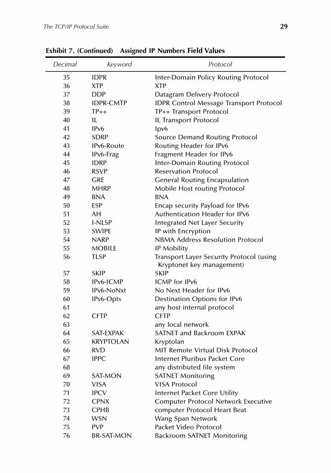
The TCP/IP Protocol Suite
29
35 IDPR Inter-Domain Policy Routing Protocol36 XTP XTP37 DDP Datagram Delivery Protocol38 IDPR-CMTP IDPR Control Message Transport Protocol39 TP++ TP++ Transport Protocol40 IL IL Transport Protocol41 IPv6 Ipv642 SDRP Source Demand Routing Protocol43 IPv6-Route Routing Header for IPv644 IPv6-Frag Fragment Header for IPv645 IDRP Inter-Domain Routing Protocol46 RSVP Reservation Protocol47 GRE General Routing Encapsulation48 MHRP Mobile Host routing Protocol49 BNA BNA50 ESP Encap security Payload for IPv651 AH Authentication Header for IPv652 I-NLSP Integrated Net Layer Security53 SWIPE IP with Encryption54 NARP NBMA Address Resolution Protocol55 MOBILE IP Mobility56 TLSP Transport Layer Security Protocol (using
Kryptonet key management)57 SKIP SKIP58 IPv6-ICMP ICMP for IPv659 IPv6-NoNxt No Next Header for IPv660 IPv6-Opts Destination Options for IPv661 any host internal protocol62 CFTP CFTP63 any local network64 SAT-EXPAK SATNET and Backroom EXPAK65 KRYPTOLAN Kryptolan66 RVD MIT Remote Virtual Disk Protocol67 IPPC Internet Pluribus Packet Core68 any distributed file system69 SAT-MON SATNET Monitoring70 VISA VISA Protocol71 IPCV Internet Packet Core Utility72 CPNX Computer Protocol Network Executive73 CPHB computer Protocol Heart Beat74 WSN Wang Span Network75 PVP Packet Video Protocol76 BR-SAT-MON Backroom SATNET Monitoring
Exhibit 7. (Continued) Assigned IP Numbers Field Values
Decimal Keyword Protocol
AU1144_ch02_fm Page 29 Thursday, October 11, 2001 1:22 PM
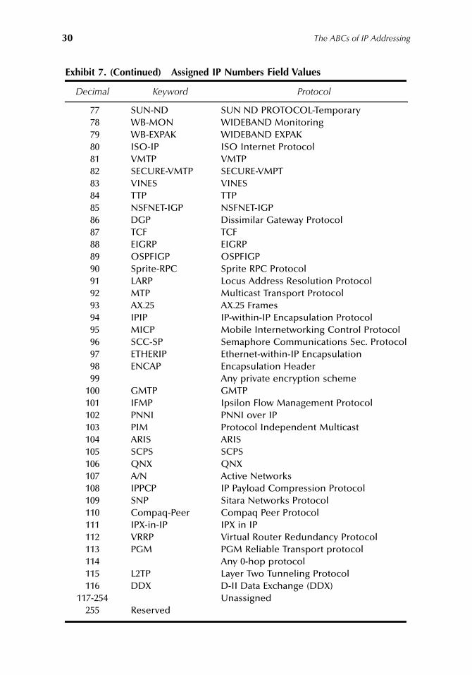
30
The ABCs of IP Addressing
77 SUN-ND SUN ND PROTOCOL-Temporary78 WB-MON WIDEBAND Monitoring79 WB-EXPAK WIDEBAND EXPAK80 ISO-IP ISO Internet Protocol81 VMTP VMTP82 SECURE-VMTP SECURE-VMPT83 VINES VINES84 TTP TTP85 NSFNET-IGP NSFNET-IGP86 DGP Dissimilar Gateway Protocol87 TCF TCF88 EIGRP EIGRP89 OSPFIGP OSPFIGP90 Sprite-RPC Sprite RPC Protocol91 LARP Locus Address Resolution Protocol92 MTP Multicast Transport Protocol93 AX.25 AX.25 Frames94 IPIP IP-within-IP Encapsulation Protocol95 MICP Mobile Internetworking Control Protocol96 SCC-SP Semaphore Communications Sec. Protocol97 ETHERIP Ethernet-within-IP Encapsulation98 ENCAP Encapsulation Header99 Any private encryption scheme
100 GMTP GMTP101 IFMP Ipsilon Flow Management Protocol102 PNNI PNNI over IP103 PIM Protocol Independent Multicast104 ARIS ARIS105 SCPS SCPS106 QNX QNX107 A/N Active Networks108 IPPCP IP Payload Compression Protocol109 SNP Sitara Networks Protocol110 Compaq-Peer Compaq Peer Protocol111 IPX-in-IP IPX in IP112 VRRP Virtual Router Redundancy Protocol113 PGM PGM Reliable Transport protocol114 Any 0-hop protocol115 L2TP Layer Two Tunneling Protocol116 DDX D-II Data Exchange (DDX)
117-254 Unassigned255 Reserved
Exhibit 7. (Continued) Assigned IP Numbers Field Values
Decimal Keyword Protocol
AU1144_ch02_fm Page 30 Thursday, October 11, 2001 1:22 PM
The TCP/IP Protocol Suite 31
Header Checksum Field
The header Checksum field contains a 16-bit Cyclic Redundancy Check (CRC)character. The CRC represents a number generated by treating the data in theIP header field as a long binary number and dividing that number by a fixedpolynomial. The result of this operation is a quotient and remainder, with theremainder being placed into the 16-bit checksum field by the transmittingdevice. When a receiving station reads the header, it also performs a CRCoperation on the received data, using the same field polynomial. If thecomputed CRC does not match the value of the CRC in the header Checksumfield, the receiver assumes the header is in error and the packet is discarded.Thus, the header Checksum, as its name implies, provides a mechanism forensuring the integrity of the IP header.
Source and Destination Address Fields
Both the Source and Destination Address fields are 32 bits in length underIPv4. The Source Address represents the originator of the datagram, while theDestination Address represents the recipient.
Under IPv4, there are five classes of IP addresses, referred to as Class Athrough Class E. Classes A, B, and C are subdivided into a network portionand a host portion and represent addresses used on the Internet and privateIP based networks. Classes D and E represent two special types of IPv4network addresses. Because it is extremely important to understand thecomposition and formation of IP addresses to correctly configure devicesconnected to an IP network as well as to design and modify such networks,Chapter 3 focuses on this topic.
Multiple Interface Addresses
One of the lesser-known aspects of IP addressing is the fact that it is possibleto assign multiple logical network addresses to one physical network. Priorto examining how this occurs, you probably want to understand the rationalefor doing this. Thus, let us assume your organization originally operated a10BASE-5 network with 100 users and wants to construct a distributed networkwithin a building that will consist of 350 workstations and server. Let us furtherassume that your organization’s previously installed 10BASE-5 coaxial basedbackbone will be used by adding 10BASE-T hubs to the backbone, with asingle router providing a connection to the Internet.
If your organization previously obtained a Class C address when it operateda 10BASE-5 network, adding 250 stations means that you would normallyrequire a second router interface and two networks because each Class Caddress supports a maximum of 254 hosts. If you have no familiarity with IPaddressing, like Indiana Jones, I will say “trust me” concerning host limitationsuntil we move on to Chapter 3.
TCP/IP supports the ability to assign multiple network addresses to acommon interface. In fact, TCP/IP also supports the assignment of multiple
AU1144_ch02_fm Page 31 Thursday, October 11, 2001 1:22 PM
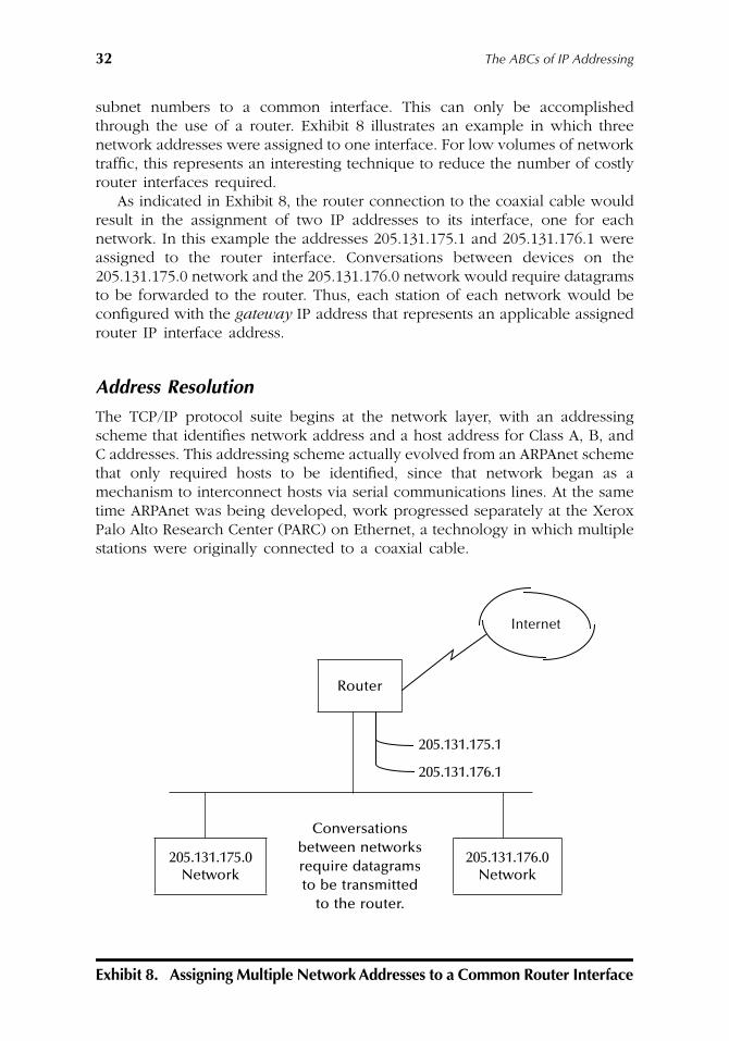
32 The ABCs of IP Addressing
subnet numbers to a common interface. This can only be accomplishedthrough the use of a router. Exhibit 8 illustrates an example in which threenetwork addresses were assigned to one interface. For low volumes of networktraffic, this represents an interesting technique to reduce the number of costlyrouter interfaces required.
As indicated in Exhibit 8, the router connection to the coaxial cable wouldresult in the assignment of two IP addresses to its interface, one for eachnetwork. In this example the addresses 205.131.175.1 and 205.131.176.1 wereassigned to the router interface. Conversations between devices on the205.131.175.0 network and the 205.131.176.0 network would require datagramsto be forwarded to the router. Thus, each station of each network would beconfigured with the gateway IP address that represents an applicable assignedrouter IP interface address.
Address Resolution
The TCP/IP protocol suite begins at the network layer, with an addressingscheme that identifies network address and a host address for Class A, B, andC addresses. This addressing scheme actually evolved from an ARPAnet schemethat only required hosts to be identified, since that network began as amechanism to interconnect hosts via serial communications lines. At the sametime ARPAnet was being developed, work progressed separately at the XeroxPalo Alto Research Center (PARC) on Ethernet, a technology in which multiplestations were originally connected to a coaxial cable.
Exhibit 8. Assigning Multiple Network Addresses to a Common Router Interface
Router
205.131.175.1
205.131.176.1
Conversations
205.131.175.0Network
between networks 205.131.176.0
Networkrequire datagrams to be transmitted
to the router.
Internet
AU1144_ch02_fm Page 32 Thursday, October 11, 2001 1:22 PM
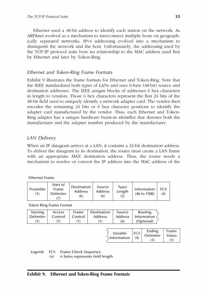
The TCP/IP Protocol Suite 33
Ethernet used a 48-bit address to identify each station on the network. AsARPAnet evolved as a mechanism to interconnect multiple hosts on geograph-ically separated networks, IPv4 addressing evolved into a mechanism todistinguish the network and the host. Unfortunately, the addressing used bythe TCP/IP protocol suite bore no relationship to the MAC address used firstby Ethernet and later by Token-Ring.
Ethernet and Token-Ring Frame Formats
Exhibit 9 illustrates the frame formats for Ethernet and Token-Ring. Note thatthe IEEE standardized both types of LANs and uses 6-byte (48-bit) source anddestination addresses. The IEEE assigns blocks of addresses 6 hex charactersin length to vendors. Those 6 hex characters represent the first 24 bits of the48-bit field used to uniquely identify a network adapter card. The vendor thenencodes the remaining 24 bits or 6 hex character positions to identify theadapter card manufactured by the vendor. Thus, each Ethernet and Token-Ring adapter has a unique hardware burnt-in identifier that denotes both themanufacturer and the adapter number produced by the manufacturer.
LAN Delivery
When an IP datagram arrives at a LAN, it contains a 32-bit destination address.To deliver the datagram to its destination, the router must create a LAN framewith an appropriate MAX destination address. Thus, the router needs amechanism to resolve or convert the IP address into the MAC address of the
Exhibit 9. Ethernet and Token-Ring Frame Formats
Ethernet Frame
Preamble (1)
Start of Frame
Delimiter (7)
Destination Address
(6)
Source Address
(6)
Type/Length
(2)
Information (46 to 1500)
FCS (4)
Token Ring Frame Format
Starting Delimiter
(1)
Access Control
(1)
Frame Control
(1)
Destination Address
(1)
Source Address
(6)
Routing Information (Optional)
Variable Information
FCS (4)
Ending Delimiter
(1)
Frame Status
(1)
Legend: FCS Frame Check Sequence(n) n bytes represents field length
AU1144_ch02_fm Page 33 Thursday, October 11, 2001 1:22 PM
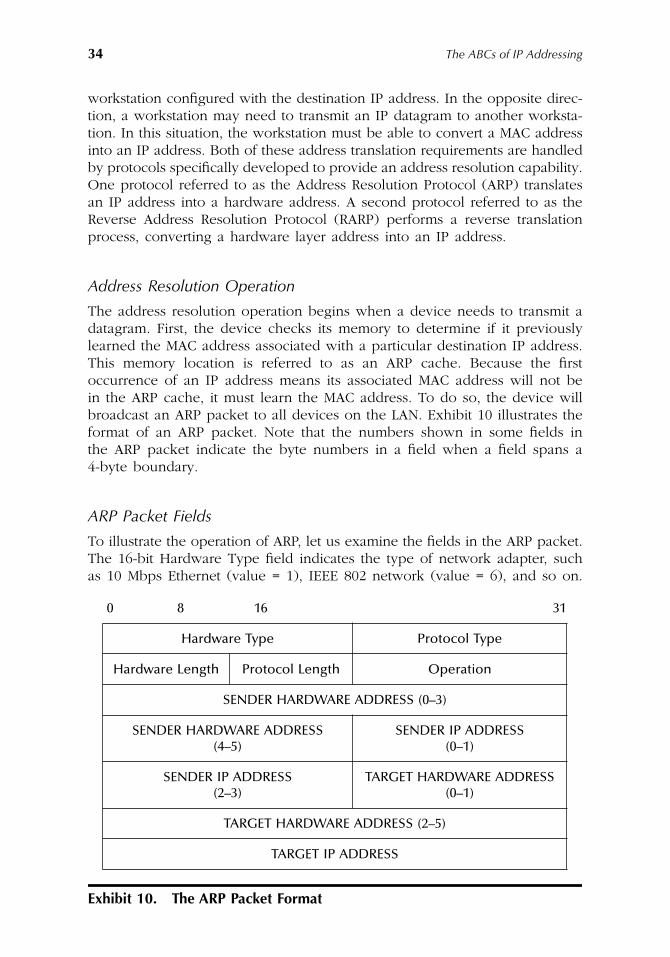
34 The ABCs of IP Addressing
workstation configured with the destination IP address. In the opposite direc-tion, a workstation may need to transmit an IP datagram to another worksta-tion. In this situation, the workstation must be able to convert a MAC addressinto an IP address. Both of these address translation requirements are handledby protocols specifically developed to provide an address resolution capability.One protocol referred to as the Address Resolution Protocol (ARP) translatesan IP address into a hardware address. A second protocol referred to as theReverse Address Resolution Protocol (RARP) performs a reverse translationprocess, converting a hardware layer address into an IP address.
Address Resolution Operation
The address resolution operation begins when a device needs to transmit adatagram. First, the device checks its memory to determine if it previouslylearned the MAC address associated with a particular destination IP address.This memory location is referred to as an ARP cache. Because the firstoccurrence of an IP address means its associated MAC address will not bein the ARP cache, it must learn the MAC address. To do so, the device willbroadcast an ARP packet to all devices on the LAN. Exhibit 10 illustrates theformat of an ARP packet. Note that the numbers shown in some fields inthe ARP packet indicate the byte numbers in a field when a field spans a4-byte boundary.
ARP Packet Fields
To illustrate the operation of ARP, let us examine the fields in the ARP packet.The 16-bit Hardware Type field indicates the type of network adapter, suchas 10 Mbps Ethernet (value = 1), IEEE 802 network (value = 6), and so on.
Exhibit 10. The ARP Packet Format
0 8 16 31
Hardware Type Protocol Type
Hardware Length Protocol Length Operation
SENDER HARDWARE ADDRESS (0–3)
SENDER HARDWARE ADDRESS (4–5)
SENDER IP ADDRESS (0–1)
SENDER IP ADDRESS (2–3)
TARGET HARDWARE ADDRESS (0–1)
TARGET HARDWARE ADDRESS (2–5)
TARGET IP ADDRESS
AU1144_ch02_fm Page 34 Thursday, October 11, 2001 1:22 PM
The TCP/IP Protocol Suite 35
The 16-bit Protocol Type field indicates the protocol for which an addressresolution process is being performed. For IP, the Protocol Type field has avalue of hex 0800.
The Hardware Length field defines the number of bytes in the hardwareaddress. Thus, the ARP packet format can be varied to accommodate differenttypes of address resolutions beyond IP and MAC addresses. Because Ethernetand Token-Ring have the same MAC length, the value of this field is 6 for both.
The Protocol Length field indicates the length of the address for the protocolto be resolved. For IPv4 the value of this field is set to 4. The Operation fieldindicates the operation to be performed. This field has a value of 1 for anARP Request. When a target station responds, the value of this field is changedto Z to denote an ARP Reply.
The Sender Hardware Address field indicates the hardware addresses ofthe station generating the ARP Request or ARP Reply. This field is 6 bytes inlength and is followed by a 4-byte Sender IP Address field. The latter indicatesthe IP address of the originator of the datagram.
The next to last field is the Target Hardware Address field. Because theARP process must discover its value, this field is originally set to all zeros inan ARP request. Once a station receives the request (and notes it has thesame IP address as that in the Target IP Address field), it places its MACaddress in the Target IP Address field. Thus, the last field, Target IP Address,is set to the IP address the originator needs for a hardware address.
Locating the Required Address
To put the pieces together, let us assume a router receives a datagram fromthe Internet with the destination IP address of 205.131.175.5. Let us furtherassume that the router has a connection to an Ethernet network and onestation on that network has that IP address. The router needs to determinethe MAC address associated with the IP address so it can construct a frameto deliver the datagram. Assuming there is no entry in its ARP cache, therouter creates an ARP frame and transmits the frame using a MAC broadcastaddress of FFFFFFFFFFFF. Because the frame was broadcast to all stations onthe network, each device reads the frame. The station that has its protocolstack configured to the same IP address as that of the Target IP Address fieldin the ARP frame would respond to the ARP Request. When it does, it willtransmit an ARP Reply in which its physical MAC address is inserted into theARP Target Hardware Address field that was previously set to zero.
The ARP standard includes provisions for devices on a network to updatetheir ARP table with the MAC and IP address pair of the sender of the ARPRequest. Thus, as ARP Requests flow on a LAN, they contribute to the buildingof tables that reduce the necessity of additional broadcasts.
Gratuitous ARP
There is a special type of ARP referred to as a gratuitous ARP that deservesmention. When a TCP/IP stack is initialized, it issues a gratuitous ARP, which
AU1144_ch02_fm Page 35 Thursday, October 11, 2001 1:22 PM
36 The ABCs of IP Addressing
represents an ARP request for its own IP address. If the station receives areply containing a MAC address that differs from its address, this indicatesthat another device on the network is using its assigned IP address. If thissituation occurs, an error message warning you of an address conflict willbe displayed.
Proxy ARP
A proxy is a device that works on the behalf of another. Thus, a proxy ARPrepresents a mechanism, which enables a device to answer an ARP requeston behalf of another device.
The rationale for the development of proxy ARP, which is also referred toas ARP Hack, dates to the early use of subnetting when a LAN could besubdivided into two or more segments. If a station on one segment requiredthe MAC address of a station on another subnet, the router would block theARP request because it is a Layer 2 broadcast, and routers operate at Layer 3.Because the router is aware of both subnets, it could answer an ARP requeston one subnet on behalf of other devices on the second subnet by supplyingits own MAC address. The originating device will then enter the router’s MACaddress in its ARP cache and will correctly transmit packets destined for theend host to the router.
RARP
The Reverse Address Resolution Protocol (RARP) was at one time quitepopular when diskless workstations were commonly used in corporations.In such situations, the workstation would know its MAC address, but beforced to learn its IP address from a server on the network. Thus, the RARPprotocol would be used by the client to access a server on the local networkand would provide the client’s IP address. Similar to ARP, RARP is a Layer 2protocol that cannot normally cross router boundaries. Some router manu-facturers implemented RARP, which allows requests and responses to flowbetween networks.
The RARP frame format is the same as ARP. The key difference betweenthe two is the setting of field values. The RARP protocol fills in the sender’shardware address and sets the IP address field to zeros. Upon receipt of theRARP frame, the RARP server fills in the IP address field and transmits theframe back to the client, reversing the ARP process.
ICMP
To conclude this section, attention will turn to the Internet Control Messageprotocol (ICMP). If we think about the IP protocol for a while, we wouldnote that there is no provision to inform a source of the fact that a datagramencountered some type of problem. This is because one of the functions of
AU1144_ch02_fm Page 36 Thursday, October 11, 2001 1:22 PM
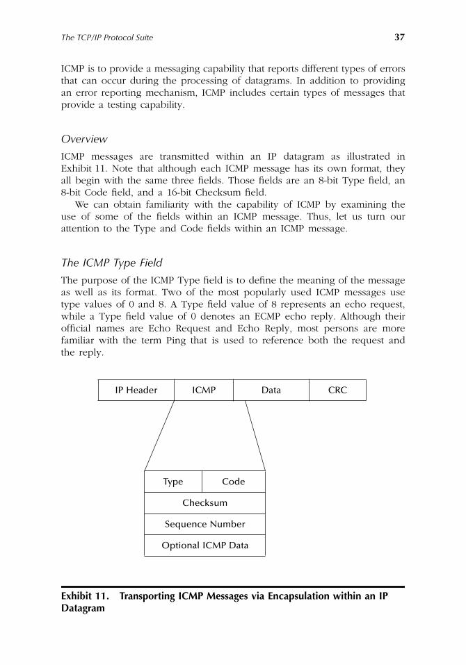
The TCP/IP Protocol Suite 37
ICMP is to provide a messaging capability that reports different types of errorsthat can occur during the processing of datagrams. In addition to providingan error reporting mechanism, ICMP includes certain types of messages thatprovide a testing capability.
Overview
ICMP messages are transmitted within an IP datagram as illustrated inExhibit 11. Note that although each ICMP message has its own format, theyall begin with the same three fields. Those fields are an 8-bit Type field, an8-bit Code field, and a 16-bit Checksum field.
We can obtain familiarity with the capability of ICMP by examining theuse of some of the fields within an ICMP message. Thus, let us turn ourattention to the Type and Code fields within an ICMP message.
The ICMP Type Field
The purpose of the ICMP Type field is to define the meaning of the messageas well as its format. Two of the most popularly used ICMP messages usetype values of 0 and 8. A Type field value of 8 represents an echo request,while a Type field value of 0 denotes an ECMP echo reply. Although theirofficial names are Echo Request and Echo Reply, most persons are morefamiliar with the term Ping that is used to reference both the request andthe reply.
Exhibit 11. Transporting ICMP Messages via Encapsulation within an IP Datagram
IP Header ICMP Data CRC
Type Code
Checksum
Sequence Number
Optional ICMP Data
AU1144_ch02_fm Page 37 Thursday, October 11, 2001 1:22 PM

38 The ABCs of IP Addressing
Exhibit 12 lists ICMP Type field values that currently identify specific typesof ICMP messages.
Exhibit 12. ICMP Type Field and Code Values
Type 0 Echo Reply MessageICMP Fields:
Type
0 for echo reply message.
Code
0
Code 0 may be received from a gateway or a host.
Type 3 Destination Unreachable MessageICMP Fields:
Type
3
Code
0 = net unreachable;
1 = host unreachable;
2 = protocol unreachable;
3 = port unreachable;
4 = fragmentation needed and DF set;
5 = source route failed.
Codes 0, 1, 4, and 5 may be received from a gateway. Codes 2 and 3 may be received from a host.
Type 4 Source Quench MessageICMP Fields:
Type
4
Code
0
Code 0 may be received from a gateway or a host.
Type 5 Source Redirect MessageICMP Fields:
Type
5
Code
0 = Redirect datagrams for the Network.
1 = Redirect datagrams for the Host.
2 = Redirect datagrams for the Type of Service and Network.
3 = Redirect datagrams for the Type of Service and Host.
Codes 0, 1, 2, and 3 may be received from a gateway.
AU1144_ch02_fm Page 38 Thursday, October 11, 2001 1:22 PM
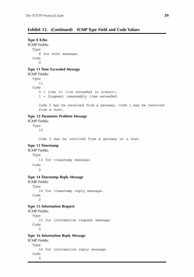
The TCP/IP Protocol Suite 39
Type 8 EchoICMP Fields:
Type8 for echo message;
Code0
Type 11 Time Exceeded MessageICMP Fields:
Type11
Code0 = time to live exceeded in transit;1 = fragment reassembly time exceeded.
Code 0 may be received from a gateway. Code 1 may be received from a host.
Type 12 Parameter Problem MessageICMP Fields:
Type12
Code 0 may be received from a gateway or a host.
Type 13 TimestampICMP Fields:
Type
13 for timestamp message;
Code
0
Type 14 Timestamp Reply MessageICMP Fields:
Type14 for timestamp reply message.
Code0
Type 15 Information RequestICMP Fields:
Type15 for information request message
Code0
Type 16 Information Reply MessageICMP Fields:
Type16 for information reply message.
Code0
Exhibit 12. (Continued) ICMP Type Field and Code Values
AU1144_ch02_fm Page 39 Thursday, October 11, 2001 1:22 PM
40 The ABCs of IP Addressing
The ICMP Code Field
The ICMP Code field provides additional information about a message definedin the Type field. The Code field may not be meaningful for certain ICMPmessages. For example, both Type field values of 0 (echo reply) and 8 (echorequest) always have a Code field value of 0. In comparison, a Type fieldvalue of 3 (Destination Unreachable) can have 1 of 16 possible Code fieldvalues, which further defines the problem. Exhibit 13 lists the Code field valuespresently assigned to ICMP messages based on their Type field values.
Evolution
Over the years from its first appearance in RFC 792, ICMP has evolved throughthe addition of many functions. For example, a Type 4 (source quench)represents the manner by which an end station indicates to the originator ofa message that the host cannot accept the rate at which the originator istransmitting packets. The recipient will send a flow of ICMP Type 4 messagesto the originator as a message for the origination to slow down its transmission.When an acceptable flow level is reached, the recipient will terminate itsgeneration of source quench messages. Although popularly used many yearsago for controlling traffic, the TCP slow-start algorithm has superseded amajority of the use of ICMP Type 4 messages.
ICMP message types that warrant discussion are Type 5 and Type 7. Arouter generates a Type 5 (redirect) message when it receives a datagram anddetermines that there is a better route to the destination network. This ICMPmessage informs the sender of the better route. A Type 7 message (timeexceeded) indicated that the time to live field value in an IP datagram headerwas decremented to 0, and the datagram was discarded. As we will note laterin this book, ICMP provides a foundation for several diagnostic testing appli-cation. Unfortunately, this testing capability can be abused by unscrupulouspersons and results in many organizations filtering ICMP messages so they donot flow from the Internet onto a private network.
The Transport LayerThe purpose of this section is to acquaint you with the two transport layerprotocols supported by the TCP/IP suite. Those protocols are the TransmissionControl Protocol (TCP) and the User Datagram Protocol (UDP).
As indicated in the section entitled The Internet Protocol and RelatedProtocols, either TCP or UDP can be identified by the setting of an applicablevalue in the IP Header. Although the use of either protocol results in theplacement of the appropriate transport layer header behind the IP header,there are significant differences between the functionality of each transportprotocol. Those differences make one protocol more suitable for certainapplications than the other protocol and vice versa.
AU1144_ch02_fm Page 40 Thursday, October 11, 2001 1:22 PM
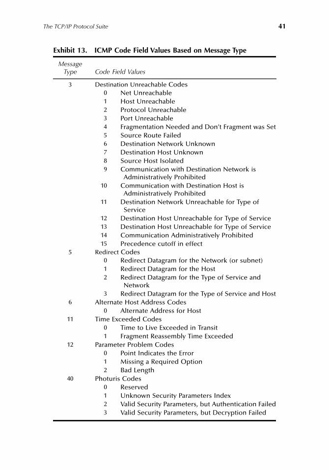
The TCP/IP Protocol Suite 41
Exhibit 13. ICMP Code Field Values Based on Message Type
Message Type Code Field Values
3 Destination Unreachable Codes0 Net Unreachable1 Host Unreachable2 Protocol Unreachable3 Port Unreachable4 Fragmentation Needed and Don’t Fragment was Set5 Source Route Failed6 Destination Network Unknown7 Destination Host Unknown8 Source Host Isolated9 Communication with Destination Network is
Administratively Prohibited10 Communication with Destination Host is
Administratively Prohibited11 Destination Network Unreachable for Type of
Service12 Destination Host Unreachable for Type of Service13 Destination Host Unreachable for Type of Service14 Communication Administratively Prohibited15 Precedence cutoff in effect
5 Redirect Codes0 Redirect Datagram for the Network (or subnet)1 Redirect Datagram for the Host2 Redirect Datagram for the Type of Service and
Network3 Redirect Datagram for the Type of Service and Host
6 Alternate Host Address Codes0 Alternate Address for Host
11 Time Exceeded Codes0 Time to Live Exceeded in Transit1 Fragment Reassembly Time Exceeded
12 Parameter Problem Codes0 Point Indicates the Error1 Missing a Required Option2 Bad Length
40 Photuris Codes0 Reserved1 Unknown Security Parameters Index2 Valid Security Parameters, but Authentication Failed3 Valid Security Parameters, but Decryption Failed
AU1144_ch02_fm Page 41 Thursday, October 11, 2001 1:22 PM
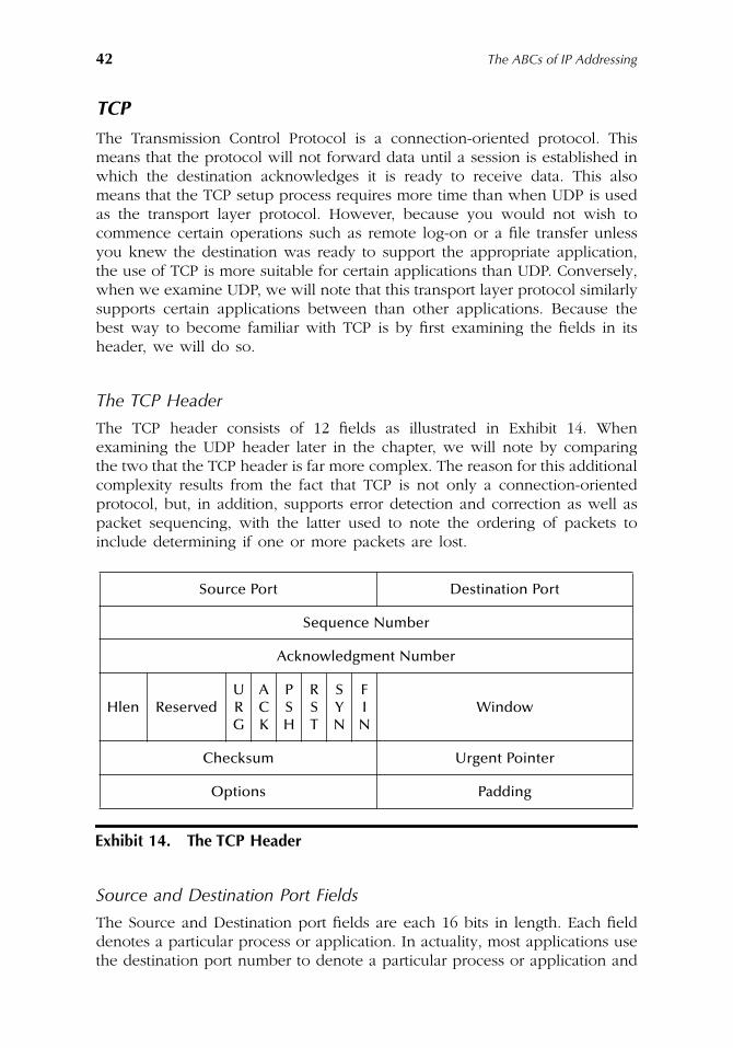
42 The ABCs of IP Addressing
TCP
The Transmission Control Protocol is a connection-oriented protocol. Thismeans that the protocol will not forward data until a session is established inwhich the destination acknowledges it is ready to receive data. This alsomeans that the TCP setup process requires more time than when UDP is usedas the transport layer protocol. However, because you would not wish tocommence certain operations such as remote log-on or a file transfer unlessyou knew the destination was ready to support the appropriate application,the use of TCP is more suitable for certain applications than UDP. Conversely,when we examine UDP, we will note that this transport layer protocol similarlysupports certain applications between than other applications. Because thebest way to become familiar with TCP is by first examining the fields in itsheader, we will do so.
The TCP Header
The TCP header consists of 12 fields as illustrated in Exhibit 14. Whenexamining the UDP header later in the chapter, we will note by comparingthe two that the TCP header is far more complex. The reason for this additionalcomplexity results from the fact that TCP is not only a connection-orientedprotocol, but, in addition, supports error detection and correction as well aspacket sequencing, with the latter used to note the ordering of packets toinclude determining if one or more packets are lost.
Source and Destination Port Fields
The Source and Destination port fields are each 16 bits in length. Each fielddenotes a particular process or application. In actuality, most applications usethe destination port number to denote a particular process or application and
Source Port Destination Port
Sequence Number
Acknowledgment Number
Hlen ReservedURG
ACK
PSH
RST
SYN
FIN
Window
Checksum Urgent Pointer
Options Padding
Exhibit 14. The TCP Header
AU1144_ch02_fm Page 42 Thursday, October 11, 2001 1:22 PM
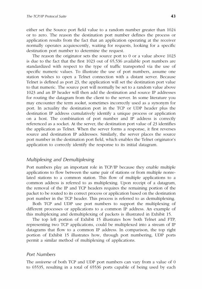
The TCP/IP Protocol Suite 43
either set the Source port field value to a random number greater than 1024or to zero. The reason the destination port number defines the process orapplication results from the fact that an application operating at the receivernormally operates acquiescently, waiting for requests, looking for a specificdestination port number to determine the request.
The reason the originator sets the source port to 0 or a value above 1023is due to the fact that the first 1023 out of 65,536 available port numbers arestandardized with respect to the type of traffic transported via the use ofspecific numeric values. To illustrate the use of port numbers, assume onestation wishes to open a Telnet connection with a distant server. BecauseTelnet is defined as port 23, the application will set the destination port valueto that numeric. The source port will normally be set to a random value above1023 and an IP header will then add the destination and source IP addressesfor routing the datagram from the client to the server. In some literature youmay encounter the term socket, sometimes incorrectly used as a synonym forport. In actuality the destination port in the TCP or UDP header plus thedestination IP address cumulatively identify a unique process or applicationon a host. The combination of port number and IP address is correctlyreferenced as a socket. At the server, the destination port value of 23 identifiesthe application as Telnet. When the server forms a response, it first reversessource and destination IP addresses. Similarly, the server places the sourceport number in the destination port field, which enables the Telnet originator’sapplication to correctly identify the response to its initial datagram.
Multiplexing and Demultiplexing
Port numbers play an important role in TCP/IP because they enable multipleapplications to flow between the same pair of stations or from multiple nonre-lated stations to a common station. This flow of multiple applications to acommon address is referred to as multiplexing. Upon receipt of a datagram,the removal of the IP and TCP headers requires the remaining portion of thepacket to be routed to its correct process or application based on the destinationport number in the TCP header. This process is referred to as demultiplexing.
Both TCP and UDP use port numbers to support the multiplexing ofdifferent processes or applications to a common IP address. An example ofthis multiplexing and demultiplexing of packets is illustrated in Exhibit 15.
The top left portion of Exhibit 15 illustrates how both Telnet and FTP,representing two TCP applications, could be multiplexed into a stream of IPdatagrams that flow to a common IP address. In comparison, the top rightportion of Exhibit 15 illustrates how, through port numbering, UDP portspermit a similar method of multiplexing of applications.
Port Numbers
The universe of both TCP and UDP port numbers can vary from a value of 0to 65535, resulting in a total of 65536 ports capable of being used by each
AU1144_ch02_fm Page 43 Thursday, October 11, 2001 1:22 PM
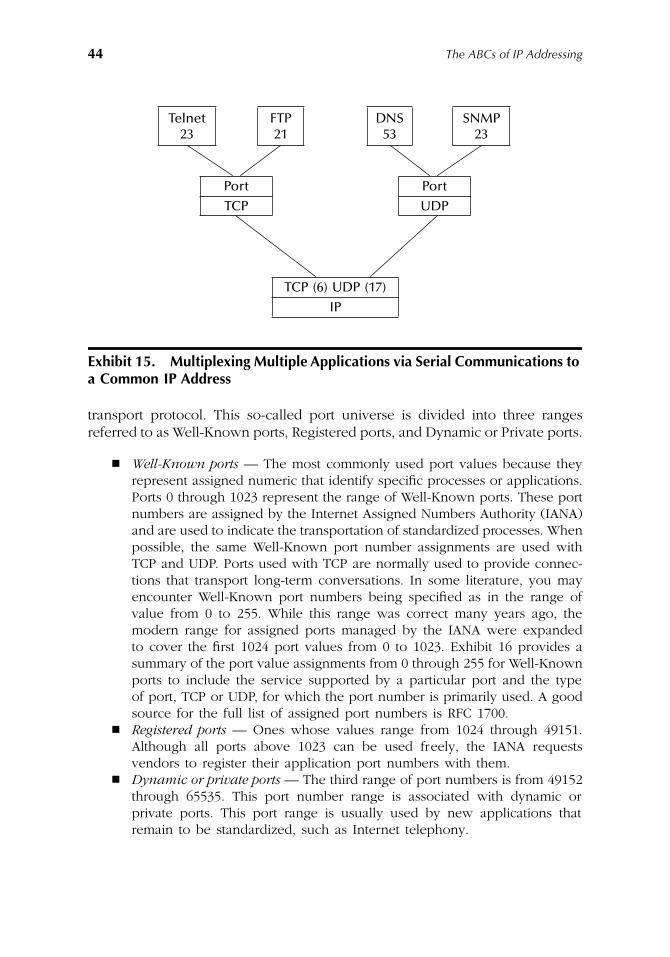
44 The ABCs of IP Addressing
transport protocol. This so-called port universe is divided into three rangesreferred to as Well-Known ports, Registered ports, and Dynamic or Private ports.
� Well-Known ports — The most commonly used port values because theyrepresent assigned numeric that identify specific processes or applications.Ports 0 through 1023 represent the range of Well-Known ports. These portnumbers are assigned by the Internet Assigned Numbers Authority (IANA)and are used to indicate the transportation of standardized processes. Whenpossible, the same Well-Known port number assignments are used withTCP and UDP. Ports used with TCP are normally used to provide connec-tions that transport long-term conversations. In some literature, you mayencounter Well-Known port numbers being specified as in the range ofvalue from 0 to 255. While this range was correct many years ago, themodern range for assigned ports managed by the IANA were expandedto cover the first 1024 port values from 0 to 1023. Exhibit 16 provides asummary of the port value assignments from 0 through 255 for Well-Knownports to include the service supported by a particular port and the typeof port, TCP or UDP, for which the port number is primarily used. A goodsource for the full list of assigned port numbers is RFC 1700.
� Registered ports — Ones whose values range from 1024 through 49151.Although all ports above 1023 can be used freely, the IANA requestsvendors to register their application port numbers with them.
� Dynamic or private ports — The third range of port numbers is from 49152through 65535. This port number range is associated with dynamic orprivate ports. This port range is usually used by new applications thatremain to be standardized, such as Internet telephony.
Exhibit 15. Multiplexing Multiple Applications via Serial Communications to a Common IP Address
Telnet23
FTP21
DNS53
SNMP23
Port Port
TCP UDP
TCP (6) UDP (17)
IP
AU1144_ch02_fm Page 44 Thursday, October 11, 2001 1:22 PM
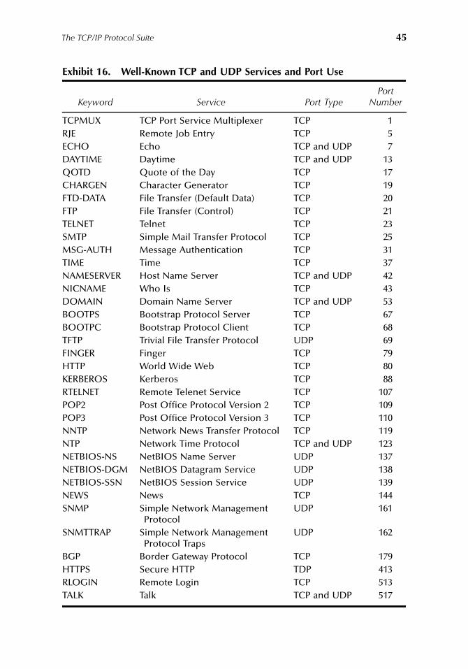
The TCP/IP Protocol Suite 45
Exhibit 16. Well-Known TCP and UDP Services and Port Use
Keyword Service Port TypePort
Number
TCPMUX TCP Port Service Multiplexer TCP 1RJE Remote Job Entry TCP 5ECHO Echo TCP and UDP 7DAYTIME Daytime TCP and UDP 13QOTD Quote of the Day TCP 17CHARGEN Character Generator TCP 19FTD-DATA File Transfer (Default Data) TCP 20FTP File Transfer (Control) TCP 21TELNET Telnet TCP 23SMTP Simple Mail Transfer Protocol TCP 25MSG-AUTH Message Authentication TCP 31TIME Time TCP 37NAMESERVER Host Name Server TCP and UDP 42NICNAME Who Is TCP 43DOMAIN Domain Name Server TCP and UDP 53BOOTPS Bootstrap Protocol Server TCP 67BOOTPC Bootstrap Protocol Client TCP 68TFTP Trivial File Transfer Protocol UDP 69FINGER Finger TCP 79HTTP World Wide Web TCP 80KERBEROS Kerberos TCP 88RTELNET Remote Telenet Service TCP 107POP2 Post Office Protocol Version 2 TCP 109POP3 Post Office Protocol Version 3 TCP 110NNTP Network News Transfer Protocol TCP 119NTP Network Time Protocol TCP and UDP 123NETBIOS-NS NetBIOS Name Server UDP 137NETBIOS-DGM NetBIOS Datagram Service UDP 138NETBIOS-SSN NetBIOS Session Service UDP 139NEWS News TCP 144SNMP Simple Network Management
ProtocolUDP 161
SNMTTRAP Simple Network Management Protocol Traps
UDP 162
BGP Border Gateway Protocol TCP 179HTTPS Secure HTTP TDP 413RLOGIN Remote Login TCP 513TALK Talk TCP and UDP 517
AU1144_ch02_fm Page 45 Thursday, October 11, 2001 1:22 PM
46 The ABCs of IP Addressing
Sequence and Acknowledgment Number Fields
TCP is a byte-oriented sequencing protocol. Thus, a Sequence field is necessaryto ensure that missing or misordered packets are noted or identified. Thatfield is 32 bits in length and provides the mechanism for ensuring that missingor misordered packets are noted or identified.
The actual entry in the Sequence Number field is based on the number ofbytes in the TCP data field, i.e., because TCP was developed as a byte-orientedprotocol, each byte in each packet is assigned a sequence number. Becauseit would be most inefficient for TCP to transmit 1 byte at a time, groups ofbytes, typically 512 or 536, are placed in a segment and 1 sequence numberis assigned to the segment and placed in the sequence field. That number isbased on the number of bytes in the current segment as well as previoussegments, because the sequence field value increments its count until all 16-bit positions are used and then continues via a rollover through zero. Forexample, assume the first TCP segment contains 512 bytes and a secondsegment will have the sequence number 1024.
The Acknowledgment Number field, which is also 32 bits in length, is usedto verify the receipt of data. The number in this field also reflects bytes. Forexample, returning to our sequence of two 512-byte segments, when the firstsegment is received, the receiver expects the next sequence number to be513. Therefore, if the receiver were acknowledging each segment, it wouldfirst return an acknowledgment with a value of 513 in the AcknowledgmentNumber field. When it acknowledges the next segment, the receiver wouldset the value in the acknowledgment number field to 1025 and so on.
Because it would be inefficient to have to acknowledge each datagram, avariable or “sliding” window is supported by the TCP protocol, i.e., returningan acknowledgment number field value of n + 1 would indicate the receiptof all bytes through byte n. If the receiver has the ability to process a seriesof multiple segments and each is received without error, it would be lessefficient to acknowledge each datagram. Thus, a TCP receiver can process avariable number of segments prior to returning an acknowledgment thatinforms the transmitter that n bytes were received correctly. To ensure lostdatagrams or lost acknowledgments do not place the TCP protocol in aninfinite waiting period, the originator sets a timer and will retransmit data ifit does not receive a response within a predefined period of time.
The previously described use of the Acknowledgment Number field isreferred to as Positive Acknowledgment Retransmission (PAR). Under PAR,each unit of data must be either implicit (sending a value of n + 1 toacknowledge receipt of n bytes) or explicit. If a unit of data is not acknowl-edged by the time the originator’s time out period is reached, the previoustransmission is retransmitted. When the Acknowledgment Number field is inuse, a flag bit, referred to as the ACK flag in the Code field, will be set. Wewill shortly discuss the six bit positions in the Code bit field.
AU1144_ch02_fm Page 46 Thursday, October 11, 2001 1:22 PM
The TCP/IP Protocol Suite 47
Hlen Field
The Header Length (Hlen) field is 4 bits in length. This field, which is alsoreferred to as the Offset field, contains a value that indicates where the TCPheader ends and the data field begins. This value is specified as a number of32-bit words. It is required due to the fact that the inclusion of options canresult in a variable length header. Because the minimum length of the TCPheader is 20 bytes, the minimum value of the Hlen field would be 5, denotingfive 32-bit words which equals 20 bytes.
Code Bits Field
As previously indicated in Exhibit 14, there are six individual 1-bit fields withinthe Code bits field. Each bit position functions as a flag to indicate whetheror not a function is enabled or disabled. Thus, to obtain an appreciation forthe use of the Code bits field, we need to examine each bit position in thatfield — which we will now do.
� URG bit — The Urgent (URG) bit or flag is used to denote an urgent orpriority activity. When such a situation occurs, an application will set theURG bit position, which acts as a flag and results in TCP immediatelytransmitting everything it has for the connection instead of waiting foradditional characters. An example of an action that could result in anapplication setting the urgent flag would be a user pressing the CTRL-BREAK key combination. A second meaning resulting from the setting ofthe urgent bit or flag is that it also indicates the Urgent Pointer field is inuse. Here the Urgent Pointer field indicates the offset in bytes from thecurrent sequence number where the urgent data is located.
� ACK bit — The setting of the ACK bit indicates that the segment containsan acknowledgment to a previously transmitted datagram or series ofdatagrams. Then the value in the acknowledgment number field indicatesthe correct receipt of all bytes through byte n by having the byte numbern + 1 in the field.
� PSH bit — The third bit position in the Code bit field is the Push (PSH)bit. This one bit field is set to request the receiver to immediately deliverdata to the application and flags any buffering. Normally the delivery ofurgent information would result in the setting of both the URG and PSHbits in the Code Bit field.
� RST bit — The fourth bit position in the Code bit field is the reset (RST)bit. This bit position is set to reset a connection. By responding to aconnection request with the RST bit set, this bit position can also be usedas a mechanism to decline a connection request.
� SYN bit — The fifth bit in the Code bit field is the Synchronization (SYN)bit. This bit position is set at start-up during what is referred to as a three-way handshake, which will be covered shortly.
� FIN bit — The sixth and last bit position in the Code bit field is the finish(FIN) bit. This bit position is set by the sender to indicate that it has noadditional data, and the connection should be released.
AU1144_ch02_fm Page 47 Thursday, October 11, 2001 1:22 PM
48 The ABCs of IP Addressing
Window Field
The Window field is 16 bits in length and provides TCP with the ability toregulate the flow of data between source and destination. Therefore, this fieldindirectly performs flow control.
The Window field indicates the maximum number of bytes that the receiv-ing device can accept. Thus, it indirectly indicates the available buffer memoryof the receiver. Here a large value can significantly improve TCP performancebecause it permits the originator to transmit a number of segments withouthaving to wait for an acknowledgment while permitting the receiver toacknowledge the receipt of multiple segments with one acknowledgment.
Because TCP is a full-duplex transmission protocol, both the originator andrecipient can insert values in the Window field to control the flow of data ineach direction. By reducing the value in the Window field, one end of asession in effect informs the other end to transmit less data. Thus, the use ofthe Window field provides a bi-directional flow control capability.
Checksum Field
The Checksum field is 16 bits or 2 bytes in length. The function of this fieldis to provide an error detection capability for TCP. To do so, this field isprimarily concerned with ensuring that key fields are validated instead ofprotecting the entire header. Thus, the Checksum calculation occurs over whatis referred to as a 12-byte pseudo header. This pseudo header includes the32-bit Source and Destination Address fields in the IP header, the 8-bit protocolfield, and a length field that indicates the length of the TCP header and datatransported within the TCP segment. Thus, the primary purpose of the Check-sum field is to ensure data arrived at its correct destination, and the receiverhas no doubt about the address of the originator nor the length of the headerand the type of application data transported.
Urgent Pointer Field
The Urgent Pointer field is 1 byte in length. The value in this field acts as apointer to the sequence number of the byte following the urgent data. Aspreviously noted, the URG bit position in the Code field must be set for thedata in the Urgent Pointer field to be interpreted.
Options
The Options field, if present, can be variable in length. The purpose of thisfield is to enable TCP to support various options, with Maximum SegmentSize (MSS) representing a popular TCP option. Because the header must endon a 32-bit boundary, any option that does not do so is extended via padcharacters that in some literature is referred to as a Padding field.
AU1144_ch02_fm Page 48 Thursday, October 11, 2001 1:22 PM
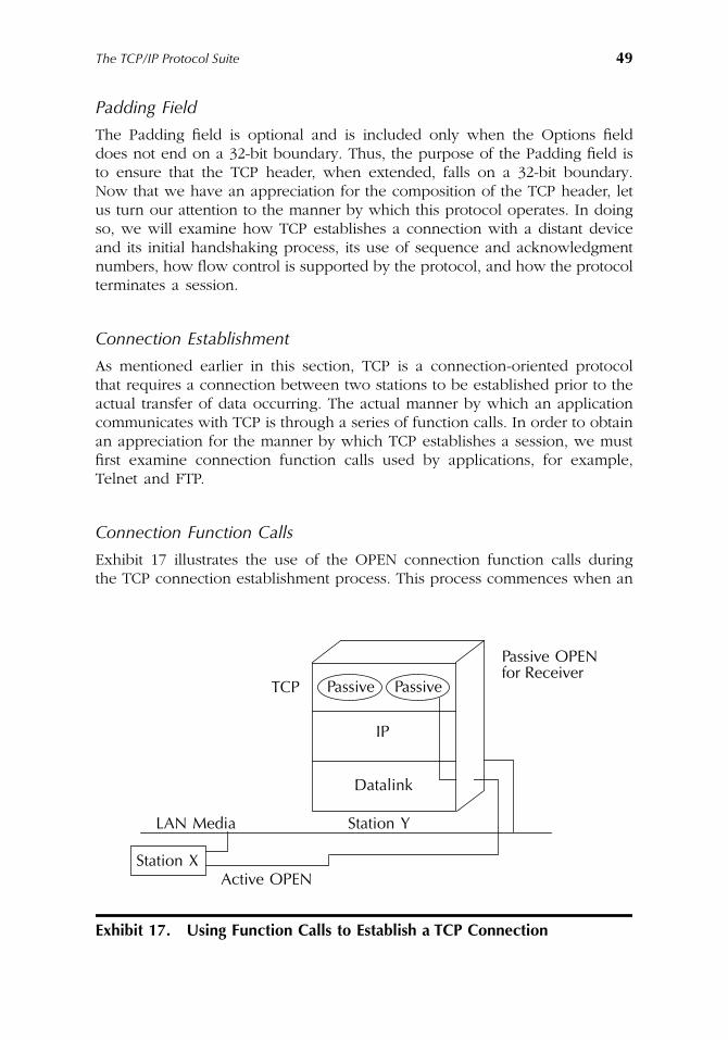
The TCP/IP Protocol Suite 49
Padding Field
The Padding field is optional and is included only when the Options fielddoes not end on a 32-bit boundary. Thus, the purpose of the Padding field isto ensure that the TCP header, when extended, falls on a 32-bit boundary.Now that we have an appreciation for the composition of the TCP header, letus turn our attention to the manner by which this protocol operates. In doingso, we will examine how TCP establishes a connection with a distant deviceand its initial handshaking process, its use of sequence and acknowledgmentnumbers, how flow control is supported by the protocol, and how the protocolterminates a session.
Connection Establishment
As mentioned earlier in this section, TCP is a connection-oriented protocolthat requires a connection between two stations to be established prior to theactual transfer of data occurring. The actual manner by which an applicationcommunicates with TCP is through a series of function calls. In order to obtainan appreciation for the manner by which TCP establishes a session, we mustfirst examine connection function calls used by applications, for example,Telnet and FTP.
Connection Function Calls
Exhibit 17 illustrates the use of the OPEN connection function calls duringthe TCP connection establishment process. This process commences when an
Exhibit 17. Using Function Calls to Establish a TCP Connection
Passive Passive
IP
Datalink
Station YLAN Media
TCP
Active OPENStation X
Passive OPENfor Receiver
AU1144_ch02_fm Page 49 Thursday, October 11, 2001 1:22 PM
50 The ABCs of IP Addressing
application requires a connection to a remote station. At that time the appli-cation will request TCP to place an OPEN function call. There are two typesof OPEN function calls, referred to as (1) passive and (2) active. A passiveOPEN function call represents a call to allow connections to be accepted froma remote station. This type of call is normally issued upon application startup,informing TCP that, for example, FTP or Telnet is active and ready to acceptconnections originating from other stations. TCP will then note that theapplication is active and will also note its port assignment. The TCP protocolwill then allow connections on that port number.
� Port hiding — One of the little known aspects of TCP is the fact that someorganizations attempt to hide their applications by configuring applicationsfor ports other than well-known ports. For example, assigning Telnet toport 2023 instead of port 23 is an example of port hiding. Although aperson with port scanning software would be able to easily discover thatport 2023 is being used, the theory behind port hiding is that it reducesthe ability of lay personnel to easily discover applications at differentnetwork addresses and then attempt to use those applications.
� Passive OPEN — Returning to the use of a passive OPEN function call, itsuse governs the number of connections allowed, i.e., while a client wouldusually issue one passive OPEN, a server would issue multiple OPENssince it is designed to service multiple sessions. Another term used for thepassive end of the TCP action is responder or TCP responder. Thus, a TCPresponder can be thought of as an opening up of connection slots toaccept any inbound connection request without waiting for any particularstation request.
� Active OPEN — A station that needs to initiate a connection to a remotestation issues the second type of OPEN call. This type of function callis referred to as an active OPEN. In the example illustrated in Exhibit17, station X would issue an active OPEN call to station Y. For theconnection to be serviced by station Y, that station must have previouslyissued a passive OPEN request which, as previously explained, allowsincoming connections to be established. To successfully connect, stationX’s active OPEN must use the same port number that the passive OPENused on station Y. In addition to active and passive OPEN calls, othercalls include CLOSE (to close a connection), SEND and RECEIVE (totransfer information), and STATUS (to receive information for a previouslyestablished connection).
Now that we have an appreciation for the use of active and passive OPENcalls to establish a TCP connection, turn to the manner by which TCP segmentsare exchanged. As we will note, the exchange of segments enables a sessionto occur. The initial exchange of datagrams that transport TCP segments isreferred to as a three-way handshake. It is important to note how and whythis process occurs. It has been used in modified form as a mechanism tocreate a denial of service (DOS) attack, which we will examine in Chapter 9.
AU1144_ch02_fm Page 50 Thursday, October 11, 2001 1:22 PM
The TCP/IP Protocol Suite 51
The Three-Way Handshake
To ensure that the sender and receiver are ready to commence the exchangeof data requires both parties to the change to be synchronized. Thus, duringthe TCP initialization process, sender and receiver exchange a few controlpackets for synchronization purposes. This exchange is referred to as a three-way handshake. This functions as a mechanism to synchronize each endpointat the beginning of a TCP connection with a sequence number and anacknowledgment number.
As we will soon note, a three-way handshake begins with the originatorsending a segment with its SYN bit in the Code bit field set. The receivingstation will respond with a similar segment with its ACK bit in the Code bitfield set. Thus, an alternate name for the three-way handshake is an initialSYN-SYN-ACK sequence.
Operation
To illustrate the three-way handshake, let us continue from our prior exampleshown in Exhibit 17, in which station X placed an active OPEN call to TCPto request a connection to a remote station and an application on that station.Once the TCP/IP protocol stack receives an active OPEN call, it will constructa TCP header with the SYN bit in the Code bit field set. The stack will alsoassign an initial sequence number and place that number in the SequenceNumber field in the TCP header. Other fields in the header, such as thedestination port number, are also set and the segment is then transferred toIP for the formation of a datagram for transmission onto the network.
To illustrate the operation of the three-way handshake, consider Exhibit 18which illustrates the process between stations X and Y. Because the initialsequence number does not have to start at zero, we will assume it commencedat 1000 and then further assume that the value was placed in the Sequencenumber field. Thus, the TCP header flowing from station X to station Y isshown with SYN=1 and SEQ=1000.
Because the IP header results in the routing of a datagram to station Y,that station strips the IP header and notes that the setting of the SYN bit inthe TCP header represents a connection request. Assuming station Y canaccept a new connection, it will acknowledge the connection request bybuilding a TCP segment. That segment will have its SYN and ACK bits in itsCode bit field set. In addition, station Y will place its own initial sequencenumber in the Sequence Number field of the TCP header it is forming. Becausethe connection request had a sequence number of 1000, station Y willacknowledge receipt by setting its Acknowledgment field value to 1001(station X sequence number plus 1) which indicates the next expectedsequence number.
Once station Y forms its TCP segment, the segment has an IP header addedto form a datagram. The datagram flows to station X. Station X receives the
AU1144_ch02_fm Page 51 Thursday, October 11, 2001 1:22 PM
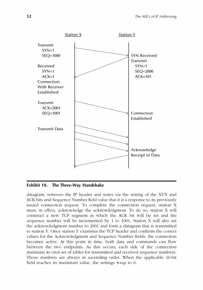
52 The ABCs of IP Addressing
datagram, removes the IP header and notes via the setting of the XYN andACK bits and Sequence Number field value that it is a response to its previouslyissued connection request. To complete the connection request, station Xmust, in effect, acknowledge the acknowledgment. To do so, station X willconstruct a new TCP segment in which the ACK bit will be set and thesequence number will be incremented by 1 to 1001. Station X will also setthe acknowledgment number to 2001 and form a datagram that is transmittedto station Y. Once station Y examines the TCP header and confirms the correctvalues for the Acknowledgment and Sequence Number fields, the connectionbecomes active. At this point in time, both data and commands can flowbetween the two endpoints. As this occurs, each side of the connectionmaintains its own set of tables for transmitted and received sequence numbers.Those numbers are always in ascending order. When the applicable 16-bitfield reaches its maximum value, the settings wrap to 0.
Exhibit 18. The Three-Way Handshake
Station X Station Y
TransmitSYN=1SEQ=1000 SYN Received
TransmitReceived SYN=1
SYN=1 SEQ=2000ACK=1 ACK=101
ConnectionWith ReceiverEstablished
TransmitACK=2001SEQ=1001 Connection
Established
Transmit Data
AcknowledgeReceipt of Data
AU1144_ch02_fm Page 52 Thursday, October 11, 2001 1:22 PM
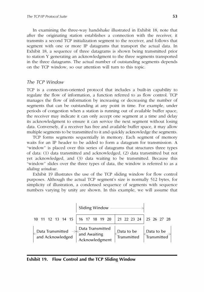
The TCP/IP Protocol Suite 53
In examining the three-way handshake illustrated in Exhibit 18, note thatafter the originating station establishes a connection with the receiver, ittransmits a second TCP initialization segment to the receiver, and follows thatsegment with one or more IP datagrams that transport the actual data. InExhibit 18, a sequence of three datagrams is shown being transmitted priorto station Y generating an acknowledgment to the three segments transportedin the three datagrams. The actual number of outstanding segments dependson the TCP window, so our attention will turn to this topic.
The TCP Window
TCP is a connection-oriented protocol that includes a built-in capability toregulate the flow of information, a function referred to as flow control. TCPmanages the flow of information by increasing or decreasing the number ofsegments that can be outstanding at any point in time. For example, underperiods of congestion when a station is running out of available buffer space,the receiver may indicate it can only accept one segment at a time and delayits acknowledgment to ensure it can service the next segment without losingdata. Conversely, if a receiver has free and available buffer space, it may allowmultiple segments to be transmitted to it and quickly acknowledge the segments.
TCP forms segments sequentially in memory. Each segment of memorywaits for an IP header to be added to form a datagram for transmission. A“window” is placed over this series of datagrams that structures three typesof data: (1) data transmitted and acknowledged, (2) data transmitted but notyet acknowledged, and (3) data waiting to be transmitted. Because this“window” slides over the three types of data, the window is referred to as asliding window.
Exhibit 19 illustrates the use of the TCP sliding window for flow controlpurposes. Although the actual TCP segment’s size is normally 512 bytes, forsimplicity of illustration, a condensed sequence of segments with sequencenumbers varying by unity are shown. In this example, we will assume that
Exhibit 19. Flow Control and the TCP Sliding Window
Sliding Window
10 11 12 13 14 15 16 17 18 19 20 21 22 23 24 25 26 27 28
Data Transmittedand Acknowledged
Data Transmitted and Awaiting Acknowledgment
Data to be Transmitted
Data to be Transmitted
AU1144_ch02_fm Page 53 Thursday, October 11, 2001 1:22 PM
54 The ABCs of IP Addressing
sequence numbers 10 through 15 have been transmitted to the destinationstation. The remote station acknowledges receipt of those segments. Datagramscontaining segment sequence numbers 16 through 20 were transmitted by thesource station, but at this particular point in time have not received anacknowledgment. Thus, that data represents the second type of data coveredby a sliding window. Note that this window will slide up the segments aseach datagram is transmitted. The third type of data covered by the sidingwindow is segments. In Exhibit 19 segments 21 through 24 are in the sourcestation awaiting transmission, while segments 25 through 28 are awaitingcoverage by the sliding window.
If we return to Exhibit 14, which illustrated the TCP header, we will notea field labeled Window. That field value indirectly governs the length of thesliding window. In addition, the setting of that field provides a flow controlmechanism. For example, the Window field transmitted by a receiver to asender indicates the range of sequence number, which equates to bytes, thatthe receiver is willing to accept. If a remote station cannot accept an additionaldata, it would then set the Window field value to zero. The receiving stationcontinues to transmit TCP segments with the Window field set to zero untilits buffer is emptied a bit (no pun intended), in effect allowing the resumptionof transmission conveying data by the originator. That is, when the transmittingstation receives a response with a Window field value of zero, it replies tothe response with an ACK (Code field ACK bit set to one) and its Windowfield set to a value of zero. This inhibits the flow of data. When sufficientbuffer space becomes available at the receiver, it will form a segment withits Window field set to a non-zero value, indicating that it can again receivedata. At this point, the transmitting of data goes to the receiver.
Avoiding Congestion
One of the initial problems associated with TCP is the fact that a connectioncould commence with the originator transmitting multiple segments, up to theWindow field value returned by the receiver during the previously describedthree-way handshake. If there are slow-speed WAN connections betweenoriginator and recipient, it is possible that routers could become saturatedwhen a series of transmissions originated at the same time. In such a situation,the router would discard datagrams, causing retransmissions that continuedthe abnormal situation. The solution developed to avoid this situation isreferred to as a TCP slow start process.
TCP Slow Start
Slow start represents an algorithm procedure added to TCP that implicitly usesa new window, referred to as the congestion window. This window is notcontained as a field in the TCP header. Instead it becomes active through the
AU1144_ch02_fm Page 54 Thursday, October 11, 2001 1:22 PM
The TCP/IP Protocol Suite 55
algorithm that defined the slow start process. That is, when a new connectionis established, the congestion window is initialized to a size of one segment,typically 512 or 536 bytes. Each time an ACK is received, the congestionwindow’s length is increased by one segment. The originator can transmit anynumber of segments up to the minimum value of the congestion window orthe Window field value (Advertised Window). Note that flow control isimposed by the transmitter in one direction through the congestion window,while it is imposed in the other direction by the receiver’s advertised Windowfield value.
Although slow start commences with a congestion window of one segment,it builds up exponentially until it reaches the Advertised Window size, i.e., itis incremented by subsequent ACKs from 1 to 2, then it is increased to 4, 8,16, and so on, until it reaches the Advertised Window size. Once this occurs,segments are transferred using the Advertised Window size for congestioncontrol and the slow start process is terminated.
The Slow Start Threshold
In addition to working at initiation, slow start will return on the occurrenceof one of two conditions: (1) duplicate ACKs or (2) a time out conditionwhere a response is not received within a predefined period of time. Wheneither situation occurs, the originator commences another algorithm referredto as the Congestion Control Algorithm.
When congestion occurs, a comparison is initiated between the CongestionWindow size and the current Advertised Window size. The smaller numberis halved and saved in a variable referred to as a slow start threshold. Theminimum value of the slow start threshold is two segments unless congestionoccurred via a time out, with the congestion window then set to a value of1, the same as a slow start process. The TCP originator has the option ofusing the slow start start-up or congestion avoidance. To determine whichmethod to use, the originator compares the congestion value to the value ofthe slow start threshold. If the congestion value matches the value of the slowstart threshold, the congestion avoidance algorithm will be used. Otherwise,the originator will use the slow start method. Since we previously describedthe slow start method, let us turn to the congestion avoidance method andto the algorithm it uses.
Upon the receipt of ACKs, the congestion window will be increased untilits value matches the value saved in the slow start threshold. When this occurs,the slow start algorithm terminates and the congestion avoidance algorithmstarts. This algorithm multiplies the segment size by two, divides that valueby the congestion window size, and then continually increases its value basedon the previously described algorithm each time an ACK is received. Theresult of this algorithm is a more linear growth in the number of segmentsthat can be transmitted in comparison to the exponential growth of the slowstart algorithm.
AU1144_ch02_fm Page 55 Thursday, October 11, 2001 1:22 PM
56 The ABCs of IP Addressing
TCP Retransmissions
While it is obvious that the negative acknowledgment of a segment by thereceiver returning the same segment number expected indicates a retransmis-sion request, what happens if a datagram is delayed? Since delays across aTCP/IP network depend on the activity of other routers in the network, thenumber of hops in the path between source and destination, and other factors,it is relatively impossible to have an exact expected delay prior to a stationassuming data is lost and retransmitting. Recognizing this situation, the devel-opers of TCP included an adaptive retransmission algorithm in the protocol.Under this algorithm, when TCP submits a segment for transmission, theprotocol records the segment sequence number and time. When an acknowl-edgment is received to that segment, TCP also records the time, obtaining around-trip delay. The TCP protocol uses such timing information to constructan average round-trip delay that is used by a timer to denote, when the timerexpires, that a retransmission should occur. When a new transmit-responsesequence occurs, another round-trip delay is computed which slightly changesthe average. Thus, this technique slowly changes the timer value that governsthe acceptable delay for waiting for an ACK. Now that we have an appreciationfor the manner by which TCP determines when to retransmit a segment, letus conclude our coverage of this protocol by turning to the manner by whichit gracefully terminates a session.
Session Termination
If we remember the components of the Code bit field, we previously notedthat field has a FIN bit. The purpose of this bit is to enable TCP to gracefullyterminate a session. Before TCP supports full-duplex communication, eachparty to the session must close the session. This means that both the originatorand recipient must change segments with the FIN bit set in each segment.
Exhibit 20 illustrates the exchange of segments to gracefully terminate aTCP connection. In this example, assume station X has completed its trans-mission and indicates this fact by sending a segment to station Y with theFIN bit set. Station Y will acknowledge the segment with an ACK. At thispoint in time, station Y will no longer accept data from station X. Station Ycan continue to accept data from its application to transmit to station X. Ifstation Y does not have any more data to transmit, it will then completelyclose the connection by transmitting a segment to station X with the FIN bitset in the segment. Station X will then ACK that segment and terminate theconnection. If an ACK should be lost in transit, segments with FIN aretransmitted and a timer is set. Then either an ACK is received or a time-outoccurs which serves to close the connection.
UDP
The User Datagram Protocol (UDP) is the second transport layer protocolsupported by the TCP/IP protocol suite. UDP is a connectionless protocol.
AU1144_ch02_fm Page 56 Thursday, October 11, 2001 1:22 PM
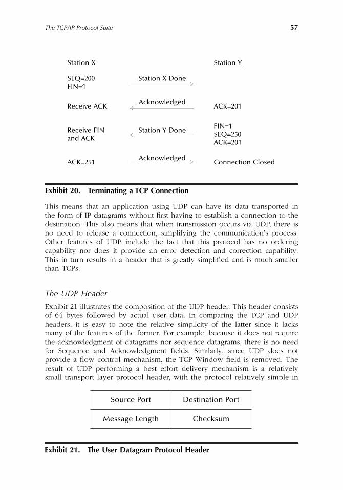
The TCP/IP Protocol Suite 57
This means that an application using UDP can have its data transported inthe form of IP datagrams without first having to establish a connection to thedestination. This also means that when transmission occurs via UDP, there isno need to release a connection, simplifying the communication’s process.Other features of UDP include the fact that this protocol has no orderingcapability nor does it provide an error detection and correction capability.This in turn results in a header that is greatly simplified and is much smallerthan TCPs.
The UDP Header
Exhibit 21 illustrates the composition of the UDP header. This header consistsof 64 bytes followed by actual user data. In comparing the TCP and UDPheaders, it is easy to note the relative simplicity of the latter since it lacksmany of the features of the former. For example, because it does not requirethe acknowledgment of datagrams nor sequence datagrams, there is no needfor Sequence and Acknowledgment fields. Similarly, since UDP does notprovide a flow control mechanism, the TCP Window field is removed. Theresult of UDP performing a best effort delivery mechanism is a relativelysmall transport layer protocol header, with the protocol relatively simple in
Exhibit 20. Terminating a TCP Connection
Source Port Destination Port
Message Length Checksum
Exhibit 21. The User Datagram Protocol Header
Station X Station Y
SEQ=200FIN=1
Station X Done
Receive ACKAcknowledged
ACK=201
Receive FINand ACK
Station Y DoneFIN=1SEQ=250ACK=201
ACK=251Acknowledged
Connection Closed
AU1144_ch02_fm Page 57 Thursday, October 11, 2001 1:22 PM
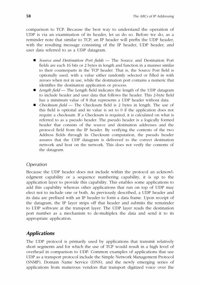
58 The ABCs of IP Addressing
comparison to TCP. Because the best way to understand the operation ofUDP is via an examination of its header, let us do so. Before we do, as areminder note that similar to TCP, an IP header will prefix the UDP header,with the resulting message consisting of the IP header, UDP header, anduser data referred to as a UDP datagram.
� Source and Destination Port fields — The Source and Destination Portfields are each 16 bits or 2 bytes in length and function in a manner similarto their counterparts in the TCP header. That is, the Source Port field isoptionally used, with a value either randomly selected or filled in withzeroes when not in use, while the destination port contains a numeric thatidentifies the destination application or process.
� Length field — The Length field indicates the length of the UDP datagramto include header and user data that follows the header. This 2-byte fieldhas a minimum value of 8 that represents a UDP header without data.
� Checksum field — The Checksum field is 2 bytes in length. The use ofthis field is optional and its value is set to 0 if the application does notrequire a checksum. If a Checksum is required, it is calculated on what isreferred to as a pseudo header. The pseudo header is a logically formedheader that consists of the source and destination addresses and theprotocol field from the IP header. By verifying the contents of the twoAddress fields through its Checksum computation, the pseudo headerassures that the UDP datagram is delivered to the correct destinationnetwork and host on the network. This does not verify the contents ofthe datagram.
Operation
Because the UDP header does not include within the protocol an acknowl-edgment capability or a sequence numbering capability, it is up to theapplication layer to provide this capability. This enables some applications toadd this capability whereas other applications that run on top of UDP mayelect not to include one or both. As previously described, a UDP header andits data are prefixed with an IP header to form a data frame. Upon receipt ofthe datagram, the IP layer strips off that header and submits the remainderto UDP software at the transport layer. The UDP layer reads the destinationport number as a mechanism to de-multiplex the data and send it to itsappropriate application.
Applications
The UDP protocol is primarily used by applications that transmit relativelyshort segments and for which the use of TCP would result in a high level ofoverhead in comparison to UDP. Common examples of applications that useUDP as a transport protocol include the Simple Network Management Protocol(SNMP), Domain Name Service (DNS), and the newly emerging series ofapplications from numerous vendors that transport digitized voice over the
AU1144_ch02_fm Page 58 Thursday, October 11, 2001 1:22 PM
The TCP/IP Protocol Suite 59
Internet and are collectively referred to as Internet Telephony. Concerningthe latter, most implementations of Internet Telephony applications use bothTCP and UDP. TCP is used for call setup, whereas UDP is used to transportdigitized voice once the setup operation is completed. Because real-time voicecannot tolerate more than a fraction of a second of delay, Internet applicationsdo not implement error detection and correction, because retransmissionswould add delays that would make reconstructed voice sound awkward.Instead, because voice does not rapidly change, applications may either“smooth” an error or drop the datagram and generate a small period of noisethat cannot effect the human ear. This is because most Internet Telephonyapplications transmit 10-ms or 20-ms slices of digitized voice, making the erroror even the loss of one of a few datagrams transmitting such slides of aconversation most difficult to notice.
AU1144_ch02_fm Page 59 Thursday, October 11, 2001 1:22 PM

AU1144_ch02_fm Page 60 Thursday, October 11, 2001 1:22 PM
61
Chapter 3
IPv4 Addressing Basics
and the DNS
In Chapter 2, we examined the TCP/IP protocol suite. We noted that the 32-bitIP address used in the IP header defines the location of the destination addressof a datagram as well as the originator of the datagram, with the latter referredto as the source IP address.
In the wonderful world of IP addressing, there are actually two types ofIP addresses: one that uses 32 bits and another that uses 128 bits. The firsttype of IP address is supported by version 4 of the IP protocol, referred toas IPv4, and is the primary focus of this chapter. The second type of IPaddressing, referred to as IPv6 because it is supported by a new version ofthe IP protocol, will be discussed in Chapter 8.
This chapter will focus attention on IPv4 addressing basics and the DomainName System (DNS). IP addressing forms the basis for configuring workstationsand servers, routers, and gateways, as well as DNS servers, and provides themechanism that ensures datagrams reach their intended destination. DNSservers that form the DNS provide a mechanism to translate host names inthe form of English or near-English mnemonics into IP addresses necessaryfor the actual routing of data. Thus, the two key topics covered in Chapter 3can be viewed as providing a mechanism for the routing of information onan intranet and Internet basis.
IPv4 Addressing
IP addresses are used by the IP to identify distinct devices, such as hosts,routers, and gateways, as well as to route data to those devices. Each devicein an IP network must be assigned to a unique IP address so that it canreceive communications addressed to it.
AU1144_ch03_fm Page 61 Thursday, October 11, 2001 1:25 PM
62
The ABCs of IP Addressing
IPv4 uses 32-bit binary numbers to identify the source and destinationaddresses in each packet. This address space provides 2,294,967,296 distinctaddressable devices, which exceeded the population of the world when theInternet was initially developed. However, the proliferation of personal com-puters, the projected growth in the use of cable modems which requireindividual IP addresses, and the fact that every interface on a gateway orrouter must have a distinct IP address has contributed to a rapid depletion ofavailable IP addresses. Recognizing that hundreds of millions of people indensely populated countries such as China and India may eventually beconnected to the Internet, and also recognizing the potential for cell phonesand even pacemakers to communicate via the Internet, the Internet ActivitiesBoard (IAB) commenced work on a replacement for the current version ofIP during 1992. Although the addressing limitations of IPv4 were of primaryconcern, the efforts of the IAB resulted in a new protocol with a number ofsignificant improvements over IPv4 to include the use of 128-bit addresses forsource and destination devices. This new version of IP, which is referred toas IPv6, was finalized during 1995 and is currently being evaluated on anexperimental portion of the Internet. Because this chapter is concerned withIPv4 addressing, we will cover the addressing schemes, address notation, hostaddress restrictions, and special addresses associated with IPv6 in Chapter 8.
Working with Binary and Hexadecimal Numbering Systems
Both IPv4 and IPv6 addressing represent the use of binary numbers. Becauseit is often convenient to represent binary numbers in hexadecimal numbers,we will briefly examine both numbering systems. This will serve as both areview as well as to make us appreciate the use of dotted decimal notationdescribed later in this chapter.
If we are familiar with the decimal numbering system, it becomes a relativelyeasy process to understand binary. However, instead of thinking of a decimalnumber as
a number
, we need to examine the number by the positions ofeach digit to obtain an appreciation for the binary numbering system. Forexample, consider the number 237 in decimal. That number represents twohundreds (2
×
10
2
) plus three tens (3
×
10
1
) plus seven ones (7
×
10
0
). Thus,on a digit positional basis, we could rewrite the number 237 as:
2
×
10
2
+ 3
×
10
1
+ 7
×
10
0
remembering that any number to the zero power has a value of one.Similar to the decimal system, the binary system uses positional notation.
However, each position in the binary numbering system only has two possiblevalues instead of ten. Also, each position in the binary numbering systemrepresents a power of two instead of a power of ten. Thus, the value of an8-bit binary number becomes:
n
×
2
7
+ n
×
2
6
+ n
×
2
5
+ n
×
2
4
+ n
×
2
3
+ n
×
2
2
+ n
×
2
1
+ n
×
2
0
AU1144_ch03_fm Page 62 Thursday, October 11, 2001 1:25 PM
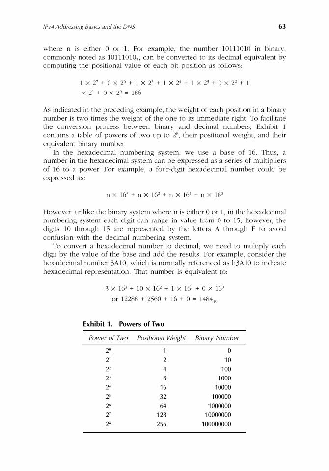
IPv4 Addressing Basics and the DNS
63
where n is either 0 or 1. For example, the number 10111010 in binary,commonly noted as 10111010
2
, can be converted to its decimal equivalent bycomputing the positional value of each bit position as follows:
1
×
2
7
+ 0
×
2
6
+ 1
×
2
5
+ 1
×
2
4
+ 1
×
2
3
+ 0
×
2
2
+ 1
×
2
1
+ 0
×
2
0
= 186
As indicated in the preceding example, the weight of each position in a binarynumber is two times the weight of the one to its immediate right. To facilitatethe conversion process between binary and decimal numbers, Exhibit 1contains a table of powers of two up to 2
8
, their positional weight, and theirequivalent binary number.
In the hexadecimal numbering system, we use a base of 16. Thus, anumber in the hexadecimal system can be expressed as a series of multipliersof 16 to a power. For example, a four-digit hexadecimal number could beexpressed as:
n
×
16
3
+ n
×
16
2
+ n
×
16
1
+ n
×
16
0
However, unlike the binary system where n is either 0 or 1, in the hexadecimalnumbering system each digit can range in value from 0 to 15; however, thedigits 10 through 15 are represented by the letters A through F to avoidconfusion with the decimal numbering system.
To convert a hexadecimal number to decimal, we need to multiply eachdigit by the value of the base and add the results. For example, consider thehexadecimal number 3A10, which is normally referenced as h3A10 to indicatehexadecimal representation. That number is equivalent to:
3
×
16
3
+ 10
×
16
2
+ 1
×
16
1
+ 0
×
16
0
or 12288 + 2560 + 16 + 0 = 1484
10
Exhibit 1. Powers of Two
Power of Two Positional Weight Binary Number
2
0
1 02
1
2 102
2
4 1002
3
8 10002
4
16 100002
5
32 1000002
6
64 10000002
7
128 100000002
8
256 100000000
AU1144_ch03_fm Page 63 Thursday, October 11, 2001 1:25 PM
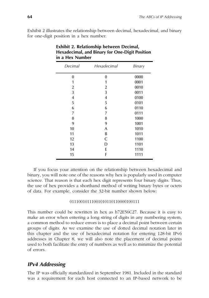
64
The ABCs of IP Addressing
Exhibit 2 illustrates the relationship between decimal, hexadecimal, and binaryfor one-digit position in a hex number.
If you focus your attention on the relationship between hexadecimal andbinary, you will note one of the reasons why hex is popularly used in computerscience. That reason is that each hex digit represents four binary digits. Thus,the use of hex provides a shorthand method of writing binary bytes or octetsof data. For example, consider the 32-bit number shown below:
01110010111001010110110000100111
This number could be rewritten in hex as h72E56C27. Because it is easy tomake an error when entering a long string of digits in any numbering system,a common method to reduce errors is to place a decimal point between certaingroups of digits. As we examine the use of dotted decimal notation later inthis chapter and the use of hexadecimal notation for entering 128-bit IPv6addresses in Chapter 8, we will also note the placement of decimal pointsused to both facilitate the entry of numbers as well as to minimize the potentialof errors.
IPv4 Addressing
The IP was officially standardized in September 1981. Included in the standardwas a requirement for each host connected to an IP-based network to be
Exhibit 2. Relationship between Decimal, Hexadecimal, and Binary for One-Digit Position
in a Hex Number
Decimal Hexadecimal Binary
0 0 00001 1 00012 2 00103 3 00114 4 01005 5 01016 6 01107 7 01118 8 10009 9 1001
10 A 101011 B 101112 C 110013 D 110114 E 111015 F 1111
AU1144_ch03_fm Page 64 Thursday, October 11, 2001 1:25 PM
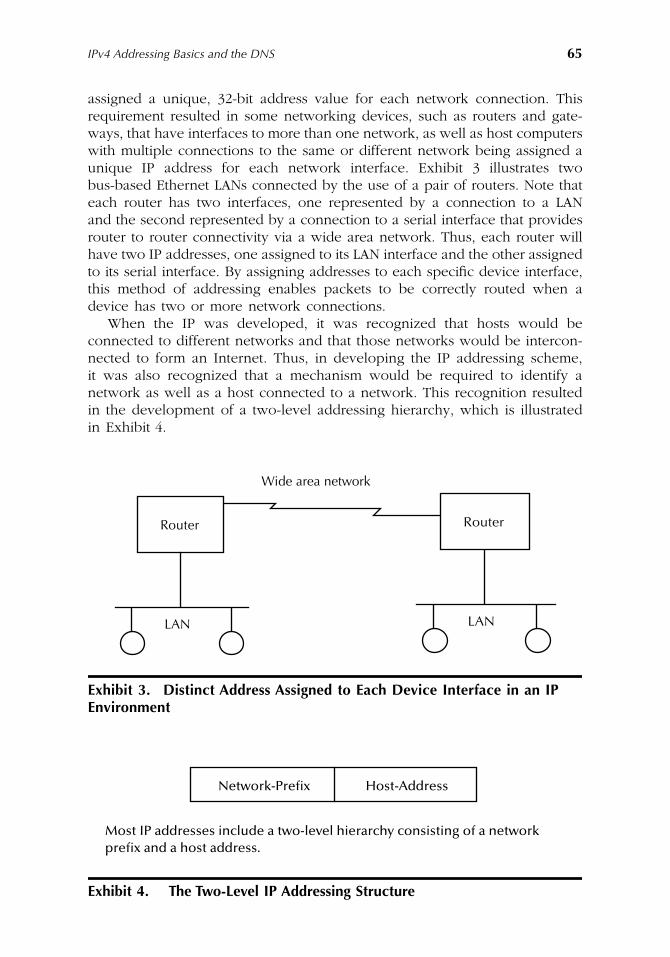
IPv4 Addressing Basics and the DNS
65
assigned a unique, 32-bit address value for each network connection. Thisrequirement resulted in some networking devices, such as routers and gate-ways, that have interfaces to more than one network, as well as host computerswith multiple connections to the same or different network being assigned aunique IP address for each network interface. Exhibit 3 illustrates twobus-based Ethernet LANs connected by the use of a pair of routers. Note thateach router has two interfaces, one represented by a connection to a LANand the second represented by a connection to a serial interface that providesrouter to router connectivity via a wide area network. Thus, each router willhave two IP addresses, one assigned to its LAN interface and the other assignedto its serial interface. By assigning addresses to each specific device interface,this method of addressing enables packets to be correctly routed when adevice has two or more network connections.
When the IP was developed, it was recognized that hosts would beconnected to different networks and that those networks would be intercon-nected to form an Internet. Thus, in developing the IP addressing scheme,it was also recognized that a mechanism would be required to identify anetwork as well as a host connected to a network. This recognition resultedin the development of a two-level addressing hierarchy, which is illustratedin Exhibit 4.
Exhibit 3. Distinct Address Assigned to Each Device Interface in an IP Environment
Exhibit 4. The Two-Level IP Addressing Structure
Router
LAN
Router
LAN
Wide area network
Most IP addresses include a two-level hierarchy consisting of a networkprefix and a host address.
Network-Prefix Host-Address
AU1144_ch03_fm Page 65 Thursday, October 11, 2001 1:25 PM
66
The ABCs of IP Addressing
Under the two-level IP addressing scheme, all hosts on the same networkmust be assigned the same network prefix, but must have a unique hostaddress to differentiate one host from another. Similarly, two hosts on differentnetworks must be assigned different network prefixes; however, the hosts canhave the same host address.
Address Classes
When IP was standardized, it was recognized that the use of a single methodof subdivision of the 32-bit address into network and host portions would bewasteful with respect to the assignment of addresses. For example, if alladdresses were split evenly, resulting in 16 bits for a network number and16 bits for a host number, the result would allow a maximum of 65,532(2
16
– 2) networks with up to 65,534 hosts per network. Then, the assignmentof a network number to an organization that only had 100 computers wouldresult in a waste of 65,434 host addresses that could not be assigned to anotherorganization. Recognizing this problem, the designers of IP decided to sub-divide the 32-bit address space into different address classes, resulting in fiveaddress classes being defined. Those classes are referred to as Class A throughClass E.
Class A addresses are for very large networks, while Class B and Class Caddresses are for medium-sized and small-sized networks, respectively.Class A, B, and C addresses incorporate the two-level IP addressing structurepreviously illustrated in Exhibit 4. Class D addresses are used for IP multi-casting, where a single message is distributed to a group of hosts dispersedacross a network. Class E addresses are reserved for experimental use. BothClass D and Class E addresses do not incorporate the two-level IP addressingstructure used by Class A through Class C addresses.
Exhibit 5 illustrates the five IP address formats to include the bit allocationof each 32-bit address class. In examining Exhibit 5, note that the addressclass can easily be determined through the examination of the values of 1 ormore of the first 4 bits in the 32-bit address. Once an address class is identified,the subdivision of the remainder of the address into the network and hostaddress portions is automatically noted. To obtain an appreciation for the useof each address class, let us examine the composition of the network andhost portion of each address when applicable to provide some basic infor-mation that can be used to indicate how such addresses are used. Concerningthe allocation of IP addresses, it should be noted that specific class addressesare assigned indirectly by the Internet Corporation for Assigned Names andNumbers (ICANN). Typically ICANN assigns blocks of IP addresses to InternetService Providers (ISPs), with the latter assigning IP addresses to subscribers.
Class A
A Class A IP address is defined by a 0-bit value in the high-order bit positionof the address. This class of addresses uses 7 bits for the network portion
AU1144_ch03_fm Page 66 Thursday, October 11, 2001 1:25 PM
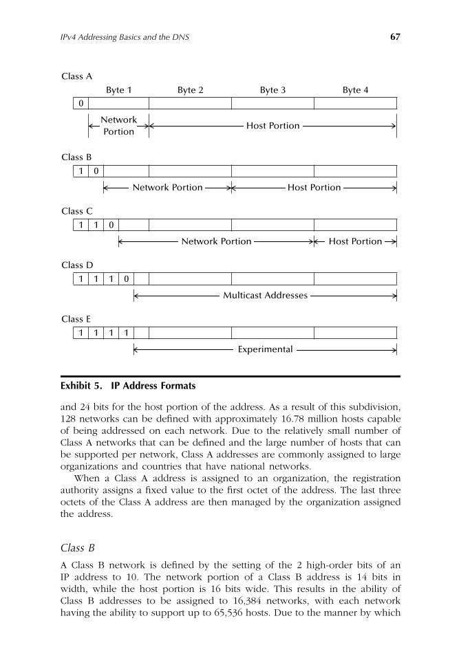
IPv4 Addressing Basics and the DNS
67
and 24 bits for the host portion of the address. As a result of this subdivision,128 networks can be defined with approximately 16.78 million hosts capableof being addressed on each network. Due to the relatively small number ofClass A networks that can be defined and the large number of hosts that canbe supported per network, Class A addresses are commonly assigned to largeorganizations and countries that have national networks.
When a Class A address is assigned to an organization, the registrationauthority assigns a fixed value to the first octet of the address. The last threeoctets of the Class A address are then managed by the organization assignedthe address.
Class B
A Class B network is defined by the setting of the 2 high-order bits of anIP address to 10. The network portion of a Class B address is 14 bits inwidth, while the host portion is 16 bits wide. This results in the ability ofClass B addresses to be assigned to 16,384 networks, with each networkhaving the ability to support up to 65,536 hosts. Due to the manner by which
Exhibit 5. IP Address Formats
Class A
Byte 1 Byte 2 Byte 3 Byte 40
NetworkHost Portion
Portion
Class B
1 0
Network Portion Host Portion
Class C
1 1 0
Network Portion Host Portion
Class D
1 1 1 0
Multicast Addresses
Class E
1 1 1 1
Experimental
AU1144_ch03_fm Page 67 Thursday, October 11, 2001 1:25 PM
68
The ABCs of IP Addressing
Class B addresses are subdivided into network and host portions, suchaddresses are normally assigned to relatively large organizations with tens ofthousands of employees.
The assignment of a Class B address results in the registration authorityproviding a fixed value to the first 2 octets of a 32-bit address. The last twooctets are then managed by the organization assigned the Class B address.
Class C
A Class C address is identified by the first 3 bits in the IP address being setto the value 110. This results in the network portion of the address having21 bits, while the host portion of the address is limited to 8-bit positions.
The use of 21 bits for a network address enables approximately 2 milliondistinct networks to be supported by the Class C address class. Because 8 bitsare used for the host portion of a Class C address, this means that each ClassC address can theoretically support up to 256 hosts. Due to the subdivisionof network and host portions of Class C addresses, they are primarily assignedfor use by relatively small networks, such as an organizational LAN. Becauseit is quite common for academic institutions, government agencies, and com-mercial organizations to have multiple LANs, it is also quite common formultiple Class C addresses to be assigned to organizations that require moreaddresses, but are not large enough to justify a Class B address. Similar toClass A and Class B addresses, the assignment of a Class C address results ina fixed value to a portion of the address while the remainder is assignableby the receiving organization. In the case of a Class C address, the registrationauthority assigns a fixed value to the first three octets, resulting in the receivingorganization controlling the last octet. Although Class A through C addressesare commonly assigned by ICANN to Internet Service Providers for distributionto their customers, Class D and E address classes represent special types ofIP addresses.
Class D
A Class D IP address is defined by the assignment of the value 1110 to thefirst 4 bits in the address. The remaining bits are used to form what is referredto as a multicast address. Thus, the 28 bits used for that address enablesapproximately 268 million possible multicast addresses.
Multicast is an addressing technique which allows a source to send a singlecopy of a frame to a specific group through the use of a multicast address.Through a membership registration process hosts can dynamically enroll inmulticast groups. Thus, the use of a Class D address enables up to 268 multicastsessions to simultaneously occur throughout the world.
Until recently the use of multicast addresses was relatively limited; however,its use can be expected to considerably increase because it provides amechanism to conserve bandwidth, which is becoming a precious commodity.
AU1144_ch03_fm Page 68 Thursday, October 11, 2001 1:25 PM
IPv4 Addressing Basics and the DNS
69
To understand how Class D addressing conserves bandwidth, consider adigitized video presentation routed from the Internet onto a private networkfor which users working at five hosts on the network wish to review. Withouta multicast transmission capability, five separate video streams would betransmitted onto the private network, with each video stream consisting offrames with five distinct host destination addresses. In comparison, throughthe use of a multicast address, one video stream would be routed to theprivate network.
Because a video stream requires a relatively high amount of bandwidthin comparison to interactive query-response client-server communications,the ability to eliminate multiple video streams via multicast transmission canprevent networks from being saturated. This capability can also result in theavoidance of session time-outs when client-server sessions are delayed dueto high LAN utilization levels, providing another reason for the use ofmulticast transmission.
Class E
The fifth address class defined by the IP address specification is a reservedaddress class known as Class E. A Class E address is defined by the first 4 bitsin the 32-bit IP address having the value of 1111. This results in the remaining28 bits being capable of supporting approximately 268.4 million addresses.Class E addresses are restricted for experimentation.
Dotted-Decimal Notation
Recognizing that the direct use of 32-bit binary addresses is both cumbersomeand unwieldy to deal with, a technique more user friendly was developed.That technique is referred to as dotted-decimal notation in recognition of thefact that the technique developed to express IP addresses occurs via the useof four decimal numbers separated from one another by decimal points.
Dotted-decimal notation divides the 32-bit IP address into four 8-bit (1-byte)fields, with the value of each field specified as a decimal number. That numbercan range from 0 to 255 in bytes 2, 3, and 4. In the first byte of an IP address,the setting of the first 4 bits in the byte used to denote the address class limitsthe range of decimal values that can be assigned to that byte. For example,from Exhibit 5, a Class A address is defined by the setting of the first bitposition in the first byte to 0. Thus, the maximum value of the first byte ina Class A address is 127. Exhibit 6 summarizes the number ranges for ClassA through Class C IP addresses.
To illustrate the formation of a dotted-decimal number, first focus attentionon the decimal relationship of the bit positions in a byte. Exhibit 7 indicatesthe decimal values of the bit positions within an 8-bit byte. Note that thedecimal value of each bit position corresponds to 2
n
, where n is the bit positionin the byte. Using the decimal values of the bit positions shown in Exhibit 7,let us assume the first byte in an IP address has its bit positions set to 11000000.
AU1144_ch03_fm Page 69 Thursday, October 11, 2001 1:25 PM
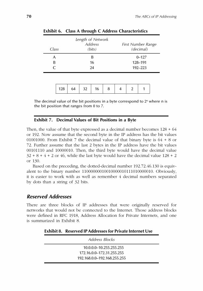
70 The ABCs of IP Addressing
Then, the value of that byte expressed as a decimal number becomes 128 + 64or 192. Now assume that the second byte in the IP address has the bit values01001000. From Exhibit 7 the decimal value of that binary byte is 64 + 8 or72. Further assume that the last 2 bytes in the IP address have the bit values00101110 and 10000010. Then, the third byte would have the decimal value32 + 8 + 4 + 2 or 46, while the last byte would have the decimal value 128 + 2or 130.
Based on the preceding, the dotted-decimal number 192.72.46.130 is equiv-alent to the binary number 11000000010010000010111010000010. Obviously,it is easier to work with as well as remember 4 decimal numbers separatedby dots than a string of 32 bits.
Reserved Addresses
There are three blocks of IP addresses that were originally reserved fornetworks that would not be connected to the Internet. Those address blockswere defined in RFC 1918, Address Allocation for Private Internets, and oneis summarized in Exhibit 8.
Exhibit 6. Class A through C Address Characteristics
Class
Length of Network Address
(bits)First Number Range
(decimal)
A B 0–127B 16 128–191C 24 192–223
128 64 32 16 8 4 2 1
The decimal value of the bit positions in a byte correspond to 2n where n is the bit position that ranges from 0 to 7.
Exhibit 7. Decimal Values of Bit Positions in a Byte
Exhibit 8. Reserved IP Addresses for Private Internet Use
Address Blocks
10.0.0.0–10.255.255.255172.16.0.0–172.31.255.255
192.168.0.0–192.168.255.255
AU1144_ch03_fm Page 70 Thursday, October 11, 2001 1:25 PM
IPv4 Addressing Basics and the DNS 71
Both security considerations as well as difficulty in obtaining large blocksof IP addresses resulted in many organizations using some of the addresseslisted in Exhibit 8 while connecting their network to the Internet. Becausethe use of any private Internet address by two or more organizations con-nected to the Internet would result in addressing conflicts and the unreliabledelivery of information, those addresses are not directly used. Instead, orga-nizations commonly install a proxy firewall that provides address translationbetween a large number of private Internet addresses used on the internalnetwork and a smaller number of assigned IP addresses. Not only does thistechnique allow organizations to connect large internal networks to theInternet without needing to obtain relatively scarce Class A or Class Baddresses, but in addition the proxy firewall hides internal addresses fromthe Internet community. This provides a degree of security because anyhacker who attempts to attack a host on your network actually has to attackyour organization’s proxy firewall.
In addition to proxy firewalls providing a network address translationcapability, many routers provide this feature. In Chapter 4 when we describeand discuss the role of special IP addresses, we will examine various networkaddress translation methods.
Networking BasicsAs previously noted, each network has a distinct network prefix and eachhost on a network has a distinct host address. When two networks areinterconnected by the use of a router, each router port is assigned an IPaddress that reflects the network to which it is connected. Exhibit 9 illustratesthe connection of two networks via a router, indicating possible addressassignments. Note that the first decimal number (192) of the 4-byte dotted-decimal numbers associated with two hosts on the network on the left portionof Exhibit 9 denotes a Class C address. This is because 192 decimal is equivalentto 11000000 binary. Since the first 2 bits are set to the bit value 11, thisindicates from Exhibit 5 a Class C address. Also note that the first 3 bytes ofa Class C address indicate the network while the fourth byte of a Class Caddress indicates the host address. Thus, the network shown in the left portionof Exhibit 9 is denoted as 192.78.46.0, with device addresses that can rangefrom 192.78.46.0 through 192.78.46.255.
In the lower right portion of Exhibit 9, two hosts are shown connected toanother network. Note that the first byte for the 4-byte dotted decimal numberassigned to each host and the router port is decimal 226, which is equivalentto binary 11100010. Because the first 2 bits in the first byte are again set to11, the second network also represents the use of a Class C address. Thus,the network address is 226.42.78.0, with device addresses on the networkranging from 226.42.78.0 to 226.42.78.255.
AU1144_ch03_fm Page 71 Thursday, October 11, 2001 1:25 PM
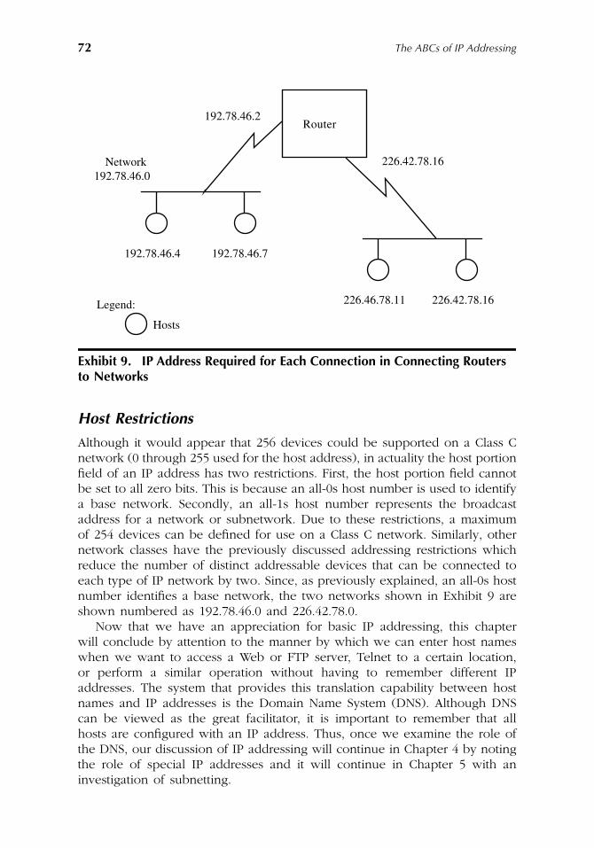
72 The ABCs of IP Addressing
Host Restrictions
Although it would appear that 256 devices could be supported on a Class Cnetwork (0 through 255 used for the host address), in actuality the host portionfield of an IP address has two restrictions. First, the host portion field cannotbe set to all zero bits. This is because an all-0s host number is used to identifya base network. Secondly, an all-1s host number represents the broadcastaddress for a network or subnetwork. Due to these restrictions, a maximumof 254 devices can be defined for use on a Class C network. Similarly, othernetwork classes have the previously discussed addressing restrictions whichreduce the number of distinct addressable devices that can be connected toeach type of IP network by two. Since, as previously explained, an all-0s hostnumber identifies a base network, the two networks shown in Exhibit 9 areshown numbered as 192.78.46.0 and 226.42.78.0.
Now that we have an appreciation for basic IP addressing, this chapterwill conclude by attention to the manner by which we can enter host nameswhen we want to access a Web or FTP server, Telnet to a certain location,or perform a similar operation without having to remember different IPaddresses. The system that provides this translation capability between hostnames and IP addresses is the Domain Name System (DNS). Although DNScan be viewed as the great facilitator, it is important to remember that allhosts are configured with an IP address. Thus, once we examine the role ofthe DNS, our discussion of IP addressing will continue in Chapter 4 by notingthe role of special IP addresses and it will continue in Chapter 5 with aninvestigation of subnetting.
Exhibit 9. IP Address Required for Each Connection in Connecting Routers to Networks
192.78.46.2
192.78.46.0Network 226.42.78.16
192.78.46.4 192.78.46.7
226.42.78.16226.46.78.11Legend:
Hosts
Router
AU1144_ch03_fm Page 72 Thursday, October 11, 2001 1:25 PM
IPv4 Addressing Basics and the DNS 73
The Domain Name SystemAlthough the use of dotted-decimal notation is certainly easier to employ than32-bit binary addresses, it is still difficult to remember a sequence of fournumerics separated by decimal points. This is certainly true when a userrequires connectivity with a large number of hosts. In addition, the use ofdotted-decimal notation does not provide an indication of the use of thedesired host nor its organization. Recognizing these limitations, ARPANETincorporated a mechanism which allowed English-type mnemonics and namesto be assigned to hosts.
During the 1970s, when ARPANET provided connectivity for a small numberof computers, a single file named HOST.TXT was used to provide a host nameto network address translation for each host on the network. That file wasmaintained at the ARPANET Network Information Center (NIC), and as thenetwork grew in size and complexity, the use of a centrally located file forname to address translations resulted in a series of problems that wereeventually alleviated by the implementation of the Domain Name System(DNS). Two of the major problems associated with the use of a singleHOST.TXT file included the traffic directed to the host maintaining the fileand available name assignments. Concerning network traffic, as more andmore hosts were added to the network, traffic routed to the host containingthe file HOST.TXT literally exploded, resulting in both transmission and hostprocessing delays. Secondly, the use of a single file for name to addresstranslations precluded two hosts from having the same name, even if theywere requested by different organizations. Recognizing these and other prob-lems associated with using a single name to address translation point resultedin the development of a distributed database to perform the same process.That database is the key to the operation of DNS.
Overview
DNS represents a client server approach that was developed to translateEnglish-type names assigned to hosts to their IP addresses. Server, moreformally referred to as name server, programs contain information aboutportions of the DNS database. Information contained in name servers isrequested via clients, which are more formally referred to as resolvers. Resolv-ers are commonly implemented as library routines within an applicationprogram, such as FTP. Such routines create queries that are transmitted to aname server. Thus, the entry of an English-type name, such as ftp.gocart.com,as the destination address in an FTP connection would result in the clientapplication sending a request to a name server for the IP address of thedestination. That IP address would then represent the address associated withthe host name ftp.gocart.com; however, in actuality the host name is ftp andthe domain name is gocart.com and the full name ftp.gocart.com is referredto as a fully qualified domain name.
AU1144_ch03_fm Page 73 Thursday, October 11, 2001 1:25 PM
74 The ABCs of IP Addressing
Database Structure
The DNS database is structured similar to an inverted tree, with its root at thetop of the structure. Directly under the root are primary domains, with eachdomain further divided into partitions referred to as subdomains. Exhibit 10indicates some of the major domain name suffixes assigned by the InterNICto include a description of the type of organization that is assigned to each suffix.
Readers should note that the entries in Exhibit 10 indicate initially definedgeneric top level domains. In addition to domains based on organizationalcategory, top level domains are also defined based on the use of two-lettercountry codes from the International Organization for Standardization’s (ISO)3166 standard. For example, AU identifies the top-level Australian domain,while FR identifies the top-level French domain. Although Exhibit 10 and thetwo preceding country domain examples use capital letters as domain iden-tifiers, in practice both generic organizational and country top-level domainsare specified as dots followed by lower case letters, such as .com, .edu, and.fr. Shortly we will obtain an understanding for the use of the dot as a prefixto the top level generic and country code identifiers.
In addition to the top-level domain names listed in Exhibit 10, during theyear 2000 the International Ad Hoc Committee (IAHC), a coalition of interna-tional groups whose actions represent a test in Internet governance by con-sensus, recommended seven new domain names. Exhibit 11 lists the newdomain name suffixes IAHC proposed.
While the IAHC recommendations have considerable influence, it is ICANNthat has the actual authority for administering domain names. During 2001ICANN proposed seven new domain name suffixes. Those new domain namesuffixes are listed in Exhibit 12. It is entirely possible that by the time you readthis book that the domain name suffixes listed in Exhibit 12 will be a reality.
Exhibit 13 provides a general schematic of the DNS database indicatingthe relationship of six top level generic domains in the DNS to each other aswell as to possible subdomains. In addition, the lower left portion of thedatabase indicates a possible registered subdomain managed by the commer-cial company International GoCart Corporation. The address of each applica-tion is formed by adding together the mnemonics assigned to each nodeupward to the top-level domain they reside in, separating each name fromthe other by a dot. Thus, what is known as the fully qualified domain namefor an ftp server would become ftp.gocart.com.
In examining Exhibit 13, it should be noted that each node represents aportion of a database and the number of domains that can be nested underone another is essentially unlimited. Similar to a file system directory structure,each domain can be identified both relative and absolute to its position inthe domain. When a domain is identified with respect to its parent domain,relative addressing is used. In comparison, when a sequence of labels is usedto identify a domain with respect to the root of the database, absoluteaddressing is employed.
To facilitate the use of domain names, each organization registers its name.The registration process results in a domain name consisting of the organization’s
AU1144_ch03_fm Page 74 Thursday, October 11, 2001 1:25 PM
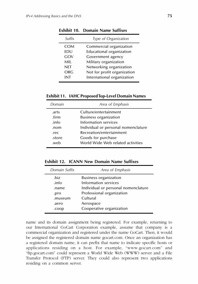
IPv4 Addressing Basics and the DNS 75
name and its domain assignment being registered. For example, returning toour International GoCart Corporation example, assume that company is acommercial organization and registered under the name GoCart. Then, it wouldbe assigned the registered domain name gocart.com. Once an organization hasa registered domain name, it can prefix that name to indicate specific hosts orapplications residing on a host. For example, “www.gocart.com” and“ftp.gocart.com” could represent a World Wide Web (WWW) server and a FileTransfer Protocol (FTP) server. They could also represent two applicationsresiding on a common server.
Exhibit 10. Domain Name Suffixes
Suffix Type of Organization
COM Commercial organizationEDU Educational organizationGOV Government agencyMIL Military organizationNET Networking organizationORG Not for profit organizationINT International organization
Exhibit 11. IAHC Proposed Top-Level Domain Names
Domain Area of Emphasis
.arts Culture/entertainment
.firm Business organization
.info Information services
.nom Individual or personal nomenclature
.rec Recreation/entertainment
.store Goods for purchase
.web World Wide Web related activities
Exhibit 12. ICANN New Domain Name Suffixes
Domain Suffix Area of Emphasis
.biz Business organization
.info Information services
.name Individual or personal nomenclature
.pro Professional organization
.museum Cultural
.aero Aerospace
.coop Cooperative organization
AU1144_ch03_fm Page 75 Thursday, October 11, 2001 1:25 PM
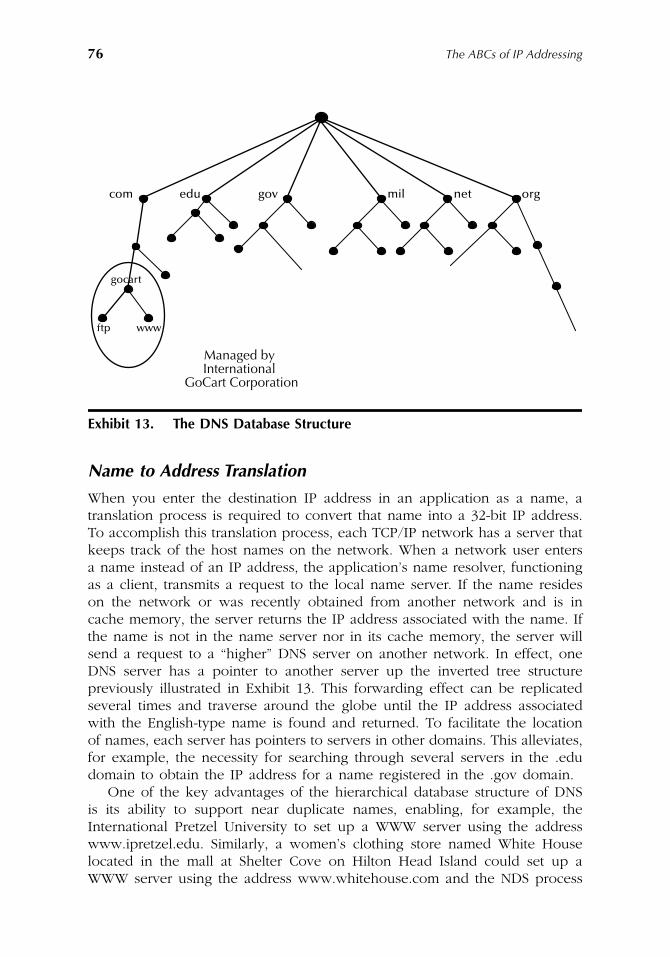
76 The ABCs of IP Addressing
Name to Address Translation
When you enter the destination IP address in an application as a name, atranslation process is required to convert that name into a 32-bit IP address.To accomplish this translation process, each TCP/IP network has a server thatkeeps track of the host names on the network. When a network user entersa name instead of an IP address, the application’s name resolver, functioningas a client, transmits a request to the local name server. If the name resideson the network or was recently obtained from another network and is incache memory, the server returns the IP address associated with the name. Ifthe name is not in the name server nor in its cache memory, the server willsend a request to a “higher” DNS server on another network. In effect, oneDNS server has a pointer to another server up the inverted tree structurepreviously illustrated in Exhibit 13. This forwarding effect can be replicatedseveral times and traverse around the globe until the IP address associatedwith the English-type name is found and returned. To facilitate the locationof names, each server has pointers to servers in other domains. This alleviates,for example, the necessity for searching through several servers in the .edudomain to obtain the IP address for a name registered in the .gov domain.
One of the key advantages of the hierarchical database structure of DNSis its ability to support near duplicate names, enabling, for example, theInternational Pretzel University to set up a WWW server using the addresswww.ipretzel.edu. Similarly, a women’s clothing store named White Houselocated in the mall at Shelter Cove on Hilton Head Island could set up aWWW server using the address www.whitehouse.com and the NDS process
Exhibit 13. The DNS Database Structure
com edu gov mil net org
wwwftp
gocart
Managed byInternational
GoCart Corporation
AU1144_ch03_fm Page 76 Thursday, October 11, 2001 1:25 PM
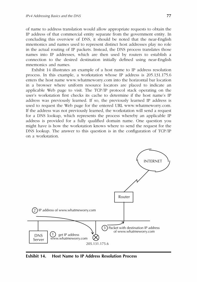
IPv4 Addressing Basics and the DNS 77
of name to address translation would allow appropriate requests to obtain theIP address of that commercial entity separate from the government entity. Inconcluding this overview of DNS, it should be noted that the near-Englishmnemonics and names used to represent distinct host addresses play no rolein the actual routing of IP packets. Instead, the DNS process translates thosenames into IP addresses, which are then used by routers to establish aconnection to the desired destination initially defined using near-Englishmnemonics and names.
Exhibit 14 illustrates an example of a host name to IP address resolutionprocess. In this example, a workstation whose IP address is 205.131.175.6enters the host name www.whatmeworry.com into the horizontal bar locationin a browser where uniform resource locators are placed to indicate anapplicable Web page to visit. The TCP/IP protocol stack operating on theuser’s workstation first checks its cache to determine if the host name’s IPaddress was previously learned. If so, the previously learned IP address isused to request the Web page for the entered URL www.whatmeworry.com.If the address was not previously learned, the workstation will send a requestfor a DNS lookup, which represents the process whereby an applicable IPaddress is provided for a fully qualified domain name. One question youmight have is how the workstation knows where to send the request for theDNS lookup. The answer to this question is in the configuration of TCP/IPon a workstation.
Exhibit 14. Host Name to IP Address Resolution Process
Router
INTERNET
IP address of www.whatmeworry.com2
get IP addresswww.whatmeworry.com1
Packet with destination IP addressof www.whatmeworry.com
3
DNSServer
205.131.175.6×
AU1144_ch03_fm Page 77 Thursday, October 11, 2001 1:25 PM
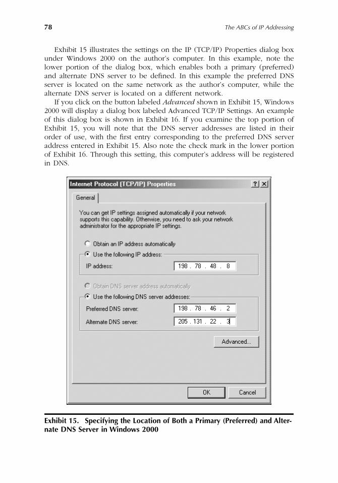
78 The ABCs of IP Addressing
Exhibit 15 illustrates the settings on the IP (TCP/IP) Properties dialog boxunder Windows 2000 on the author’s computer. In this example, note thelower portion of the dialog box, which enables both a primary (preferred)and alternate DNS server to be defined. In this example the preferred DNSserver is located on the same network as the author’s computer, while thealternate DNS server is located on a different network.
If you click on the button labeled Advanced shown in Exhibit 15, Windows2000 will display a dialog box labeled Advanced TCP/IP Settings. An exampleof this dialog box is shown in Exhibit 16. If you examine the top portion ofExhibit 15, you will note that the DNS server addresses are listed in theirorder of use, with the first entry corresponding to the preferred DNS serveraddress entered in Exhibit 15. Also note the check mark in the lower portionof Exhibit 16. Through this setting, this computer’s address will be registeredin DNS.
Exhibit 15. Specifying the Location of Both a Primary (Preferred) and Alter-nate DNS Server in Windows 2000
AU1144_ch03_fm Page 78 Thursday, October 11, 2001 1:25 PM
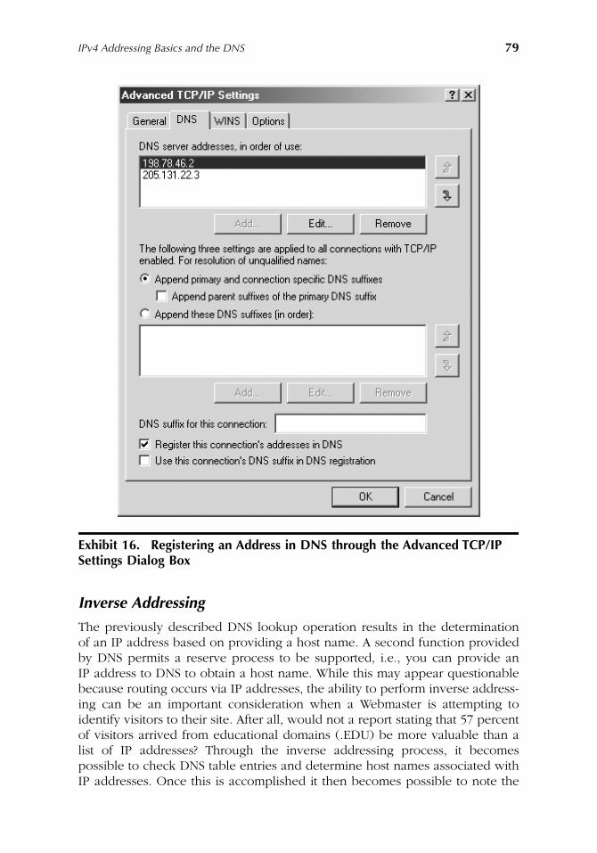
IPv4 Addressing Basics and the DNS 79
Inverse Addressing
The previously described DNS lookup operation results in the determinationof an IP address based on providing a host name. A second function providedby DNS permits a reserve process to be supported, i.e., you can provide anIP address to DNS to obtain a host name. While this may appear questionablebecause routing occurs via IP addresses, the ability to perform inverse address-ing can be an important consideration when a Webmaster is attempting toidentify visitors to their site. After all, would not a report stating that 57 percentof visitors arrived from educational domains (.EDU) be more valuable than alist of IP addresses? Through the inverse addressing process, it becomespossible to check DNS table entries and determine host names associated withIP addresses. Once this is accomplished it then becomes possible to note the
Exhibit 16. Registering an Address in DNS through the Advanced TCP/IP Settings Dialog Box
AU1144_ch03_fm Page 79 Thursday, October 11, 2001 1:25 PM
80 The ABCs of IP Addressing
domains of visitors and gather more meaningful statistics than a simple list ofIP addresses.
Inverse addressing operates based on tables maintained on the previouslymentioned Internet hosts referred to as Domain Name Servers. As previouslynoted, DNS servers provide a local name service that maps host names to IPaddresses and domain names to name servers that know about the collectionof hosts in a domain.
To illustrate the operation of inverse addressing, assume GoCart Corpora-tion’s network is connected to the Internet via an ISP. Then, the names of thepublicly accessible hosts and Web servers on GoCart’s network will be regis-tered in the ISP’s Domain Name Server. The ISP’s DNS is then designated asthe authoritative Name Server for the gocart.com domain as well as otherdomains served by the ISP. This also means that the ISP Name Server isregistered as the name server for those domains in the Internet’s master rootzone files at the top of an inverted tree hierarchy.
In actuality, each ISP, unless it is very small, typically maintains two ormore Name Servers. This provides a level of redundancy and the root zonefile at the top of the hierarchy would then contain the IP addresses of eachName Server.
Under inverse addressing which provides a mechanism to translate an IPaddress to its corresponding host or domain name, a different set of tables isused. Each DNS that maintains host-to-IP address tables also maintains tablesfor use by .arpa, a special top-level domain. Named for the original AdvancedResearch Projects Agency (ARPA) from which the Internet evolved, the .arpadomain is at the same level of the top-level domains, such as .com, .edu, .mil,and so on. However, unlike the other top-level domains that have lower-leveldomains containing near-English mnemonics, the .arpa domain has lower-leveldomains that represent IP addresses. In actuality, the .arpa domain has onlyone domain directly under it, which is the .in-addr domain. This domain hasa large number of subdomains, each representing an IP address that appearselsewhere in DNS tables as an association with a host name. Actual IPaddresses in the subdomains are arranged backward from the normal IPaddress. For example, if the IP address of a host is 205.135.173.8, it is placedin the .in-addr domain entry as 8.173.135.205. The rationale for the backwardplacement of IP addresses results from the hierarchical structure of host namesand IP addresses.
To illustrate the rationale for the reverse address, let us assume GoCartCorporation’s Web server has the IP address 205.135.173.8. When usinghost names such as www.gocart.com, the lowest level of the naminghierarchy (www) represents the least significant portion of the host name.However, under the hierarchy of numeric IP addressing, the oppositesituation occurs, i.e., for the address 205.135.173.8, the most significantportion of the address is the network portion (205) while the least significantportion (8) comes last.
AU1144_ch03_fm Page 80 Thursday, October 11, 2001 1:25 PM
IPv4 Addressing Basics and the DNS 81
Operation
Let us assume the Web server www.gocart.com wants to determine who isvisiting its site. When it receives a hit on its home page, it knows whotransmitted the hit since the source IP address is contained in the IP headerof the datagram transporting Web traffic. To perform a reverse address lookup,the Web server will transmit a reverse lookup request to its DNS. That requestprovides the IP address and requests the host name. The DNS will first checkits local reverse lookup table to determine if it has an entry. If so, it willreturn the host name to the Web server. If not, it will send a request to theName Server for the correct in-addr.arpa domain which will return the desiredhost name.
Prior to moving on, it should be mentioned that we will return to thesettings or configuration of workstations in Chapters 4 and 5. The rationalefor not mentioning the specific configuration of a workstation for TCP/IPoperations at this time is because we need to learn a bit more, no punintended, about IP addressing. Thus, after we discuss the role of special IPaddresses in Chapter 4 and subnetting in Chapter 5, we will then have thebackground to understand the do’s and don’ts associated with IP addressingand may turn our attention to the configuration process.
Returning to the DNS process, let us assume our request for a DNS lookupto the preferred DNS server does not result in a match for our query. Thatserver has a pointer to a “higher” DNS server, which might be the DNS serverof our Internet Service Provider. Thus, the preferred DNS server now sends aquery to the ISP DNS server. If the ISP DNS server does not have an entry forthe lookup request, it uses its pointer record to send a request to a higherDNS server, perhaps one located at a Network Service Provider (NSP). Eachtime the request is forwarded, an additional time delay occurs based on networktraffic and the activity of each DNS server. Thus, one of two things will happen.Either a timer set to a predefined value on the workstation will expire and anerror message will be displayed or the lookup will succeed and the applicableIP address will be returned to the workstation. When the first situation occurs,the workstation will display a dialog box asking you to check the name entered.After you click on the button labeled OK, you can simply try again. There isa very good chance that your second request, if your spelling was in order,to go to a new address will succeed. This is because as DNS requests wentup the inverted tree hierarchy, the response flowed down the hierarchy andintermediate DNS servers placed the learned information into memory. Thus,while it took too long to retrieve the required information the first time, whenthe second request occurred, it did not have to flow up the entire hierarchy.If the second situation occurs, the host name and IP address are entered inthe preferred DNS server’s cache as well as your workstation’s cache memory,simplifying the next request to the host name.
Now that we have an appreciation for IPv4 addressing and the role of theDNS, we will move on to Chapter 4 to learn the role of special IP addresses.
AU1144_ch03_fm Page 81 Thursday, October 11, 2001 1:25 PM

AU1144_ch03_fm Page 82 Thursday, October 11, 2001 1:25 PM
83
Chapter 4
The Role of Special IP
Addresses
In Chapter 3, we focused on understanding basic IPv4 addressing and therole of the Domain Name System. We also reviewed binary and hexadecimalnumbering and the composition of different IP addresses. Although we brieflymentioned RFC 1918 addresses in Chapter 3, a discussion of the role of specialIP addresses (to include RFC 1918 addresses) was deferred until this chapter.Thus, the purpose of this chapter is to obtain a detailed understanding of therole of special IP addresses and the restrictions they place on the configurationand operation of devices in a TCP/IP network environment.
The Loopback Address
When IPv4 addresses were being classified, it was recognized that there wouldbe a need to test the protocol stack. This need was satisfied through theassignment of a special address referred to as a loopback address.
Address Range
By convention, any address commencing with 127 as its first dotted decimalposition is reserved for a loopback address. Unfortunately, this schemereserves the entire Class A address space for network 127.0.0.0, resulting in2
16
numbers being reserved for loopback addresses. In practice, as we willshortly discuss, not all operating systems reserve the entire Class A 127network for loopback addresses.
AU1144_ch04_fm Page 83 Thursday, October 11, 2001 1:26 PM
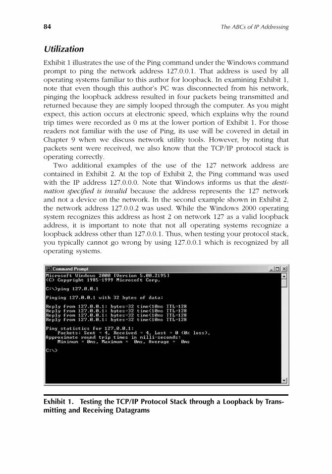
84
The ABCs of IP Addressing
Utilization
Exhibit 1 illustrates the use of the Ping command under the Windows commandprompt to ping the network address 127.0.0.1. That address is used by alloperating systems familiar to this author for loopback. In examining Exhibit 1,note that even though this author’s PC was disconnected from his network,pinging the loopback address resulted in four packets being transmitted andreturned because they are simply looped through the computer. As you mightexpect, this action occurs at electronic speed, which explains why the roundtrip times were recorded as 0 ms at the lower portion of Exhibit 1. For thosereaders not familiar with the use of Ping, its use will be covered in detail inChapter 9 when we discuss network utility tools. However, by noting thatpackets sent were received, we also know that the TCP/IP protocol stack isoperating correctly.
Two additional examples of the use of the 127 network address arecontained in Exhibit 2. At the top of Exhibit 2, the Ping command was usedwith the IP address 127.0.0.0. Note that Windows informs us that the
desti-nation specified is invalid
because the address represents the 127 networkand not a device on the network. In the second example shown in Exhibit 2,the network address 127.0.0.2 was used. While the Windows 2000 operatingsystem recognizes this address as host 2 on network 127 as a valid loopbackaddress, it is important to note that not all operating systems recognize aloopback address other than 127.0.0.1. Thus, when testing your protocol stack,you typically cannot go wrong by using 127.0.0.1 which is recognized by alloperating systems.
Exhibit 1. Testing the TCP/IP Protocol Stack through a Loopback by Trans-mitting and Receiving Datagrams
AU1144_ch04_fm Page 84 Thursday, October 11, 2001 1:26 PM
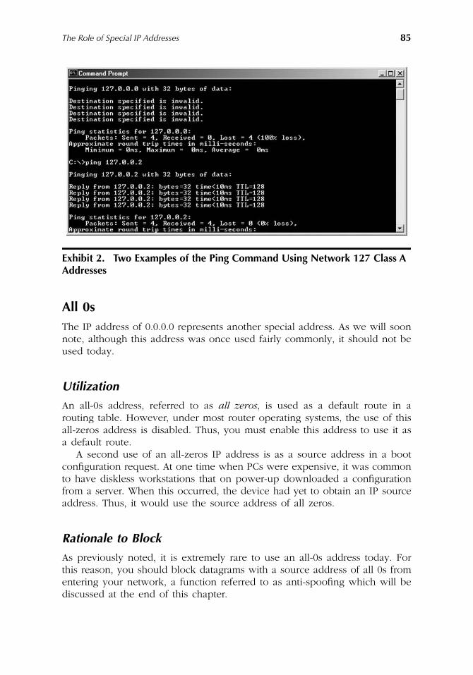
The Role of Special IP Addresses
85
All 0s
The IP address of 0.0.0.0 represents another special address. As we will soonnote, although this address was once used fairly commonly, it should not beused today.
Utilization
An all-0s address, referred to as
all zeros
, is used as a default route in arouting table. However, under most router operating systems, the use of thisall-zeros address is disabled. Thus, you must enable this address to use it asa default route.
A second use of an all-zeros IP address is as a source address in a bootconfiguration request. At one time when PCs were expensive, it was commonto have diskless workstations that on power-up downloaded a configurationfrom a server. When this occurred, the device had yet to obtain an IP sourceaddress. Thus, it would use the source address of all zeros.
Rationale to Block
As previously noted, it is extremely rare to use an all-0s address today. Forthis reason, you should block datagrams with a source address of all 0s fromentering your network, a function referred to as anti-spoofing which will bediscussed at the end of this chapter.
Exhibit 2. Two Examples of the Ping Command Using Network 127 Class A Addresses
AU1144_ch04_fm Page 85 Thursday, October 11, 2001 1:26 PM
86
The ABCs of IP Addressing
Broadcast Address
A broadcast address represents an address transmitted to every host on anetwork. In actuality only one datagram is transmitted; however, because ofthe contents of the destination address in the IP header, each device on thenetwork reads the datagram. There are several IP address patterns that areused for broadcasts. In general, a datagram can be broadcast to one or morenetworks within a particular network hierarchy.
Basic Broadcast Address
The basic IP broadcast address is 255.255.255.255, which represents an addressconsisting of all ones or 32 ones under IPv4 addressing. The use of thisaddress results in a datagram being broadcast to each system on the local link.
Utilization
The primary use of an all-ones broadcast address is in the BOOTP and DHCPprotocols. Under these protocols, a client does not know its IP address. Thus,it uses the broadcast address of 255.255.255.255 to obtain its IP address andother initialization data from a boot server. For example, a client would transmita boot request to address 255.255.255.255 and use the reserved address of allzeros (0.0.0.0) as its source IP address.
Use of All Zeros
During the early days in the evolution of the TCP/IP protocol stack, an all-zerosaddress was used instead of an all-1s address for broadcasting. This practicerepresents a nonstandard use of an antiquated method of broadcasting andshould be avoided.
Broadcasts to Networks
A second version of the broadcast address is to transmit it in a datagram toa specific remote network. This type of broadcast is referred to as a broadcastto a network. As we will soon note, this can be very dangerous.
Utilization
You can transmit an IP datagram to every host on a selected network bysetting the entire host portion of the address to all ones. For example, assumeyou want to transmit a message to every host on the Class C network205.131.175.0. Because the host portion of the IP address is the fourth byteof the address, you would set the broadcast address as 205.131.175.255.
AU1144_ch04_fm Page 86 Thursday, October 11, 2001 1:26 PM
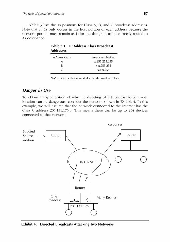
The Role of Special IP Addresses
87
Exhibit 3 lists the 1s positions for Class A, B, and C broadcast addresses.Note that all 1s only occurs in the host portion of each address because thenetwork portion must remain as is for the datagram to be correctly routed toits destination.
Danger in Use
To obtain an appreciation of why the directing of a broadcast to a remotelocation can be dangerous, consider the network shown in Exhibit 4. In thisexample, we will assume that the network connected to the Internet has theClass C address 205.131.175.0. This means there can be up to 254 devicesconnected to that network.
Exhibit 3. IP Address Class Broadcast
Addresses
Address Class Broadcast Address
A x.255.255.255B x.x.255.255C x.x.x.255
Note:
x indicates a valid dotted decimal number.
Exhibit 4. Directed Broadcasts Attacking Two Networks
One
Responses
RouterSpoofedSourceAddress
INTERNET
Router
Router
BroadcastMany Replies
205.131.175.0
AU1144_ch04_fm Page 87 Thursday, October 11, 2001 1:26 PM
88
The ABCs of IP Addressing
Assume a distant party transmits a Ping to the broadcast address of thenetwork shown in Exhibit 4. To do so, the person simply enters the followingcommand:
Ping 205.131.175.255
This entry results in the transmission of four pings to the router serving the205.131.175.255 network, where the datagram containing each ping is con-verted into an Ethernet frame and transmitted as a data link Layer 2 MediaAccess Control (MAC) broadcast onto the network. Each active powered-upstation responds to each ping, resulting in up to 254 responses flowing on thedistant network to the router and then over its serial connection to the Internet.
Because each ping command generates four datagrams containing theapplicable ICMP message, the remote network could issue up to 254
×
4 or1016 responses. Now assume the pingologist decides to use an option thatresults in the continuous pinging of the distant network’s broadcast address.To make matters a bit worse, assume the distant pingologist hides his or hertrue network address by configuring their workstation with a different IPaddress than their valid address. Because routers only check the destinationaddress in IP datagrams, this is a perfectly valid method for hiding one’s IPaddress, commonly referred to as address spoofing. To make matters evenmore alarming, assume the pingologist configured his or her IP address tothat of the FBI Web server. This means that a two-phase attack could result.Directed broadcasts to the 205.131.176.255 address first result in a continuoustransmission of echo replies generated by devices on that network. Then,because the FBI’s Web server address was configured as the pingologist’s IPaddress, the responses now flow toward the FBI server. Thus, instead of beingable to generate a traffic load that can adversely affect one network, theperson pinging away now has the capability to adversely affect two networks.
Countermeasure
Because of the potential adverse effect from directed broadcasts, most orga-nizations configure their routers to drop directed broadcasts. In a Cisco routerenvironment, you would use the command around no IP-directed broadcaststo preclude directed broadcasts from getting through your router.
Subnet Broadcast Addresses
Although we will defer discussion of subnets and subnetting to Chapter 5, itis important to note that each subnet has a broadcast address. This means itis possible for a broadcast to be directed to a specific subnet. The subnet canbe a one that a host is directly connected to or one that is remote from thesource host.
If the destination subnet is remote from the source host, the result will besimilar to the previously mentioned direct broadcast, i.e., one IP datagram
AU1144_ch04_fm Page 88 Thursday, October 11, 2001 1:26 PM
The Role of Special IP Addresses
89
with the broadcast address of a subnet would reach a router connected tothe subnet. The router would then transmit a Layer 2 Medical Access Control(MAC) frame with a physical broadcast address in the destination address ofthe frame. Each host active on the subnet would then respond.
Reserved Address
As noted in Chapter 3, each network cannot use the host address of 0 or255. A similar restriction concerning the broadcast address of subnets applies,i.e., the broadcast address of a subnet represents a reserved IP address thatcannot be assigned to a host. Chapter 5 will examine in detail how to dividea network address into subnets and how to determine the broadcast addresson each subnet.
RFC 1918 Addresses
As previously noted in Chapter 3, there are three blocks of addresses that arereserved for use for networks that will not be connected to the Internet. Thoseaddress blocks are:
10.0.0.0 to 10.255.255.255
172.16.0.0 to 172.31.255.255
192.168.0.0 to 192.168.255.255
Utilization
Perhaps the most common use of RFC 1918 addresses is as a mechanism toalleviate the shortage of IPv4 addresses, i.e., an organization with thousandsof hosts could use RFC 1918 addresses behind a router or firewall that isconnected to the Internet. Through the process of Network Address Translation(NAT) (covered in Chapter 7), it becomes possible to translate RFC 1918addresses into a valid Class C IP address. An example of this method ofaddress translation is shown in Exhibit 5. In examining Exhibit 5, note thatthe use of a single Class C network address results in 254 valid IPv4 addressesbeing used to support an entire organization’s infrastructure, which couldtheoretically represent tens of thousands of hosts.
Key Disadvantage
While RFC 1918 addresses provide a significant benefit by extending the useof scarce IPv4 addresses, they also have one key disadvantage. That disad-vantage results from the fact that many hackers like to use such addresses astheir source address when attacking a network. This use results from the factthat source addresses are not checked by routers. In addition, because RFC
AU1144_ch04_fm Page 89 Thursday, October 11, 2001 1:26 PM
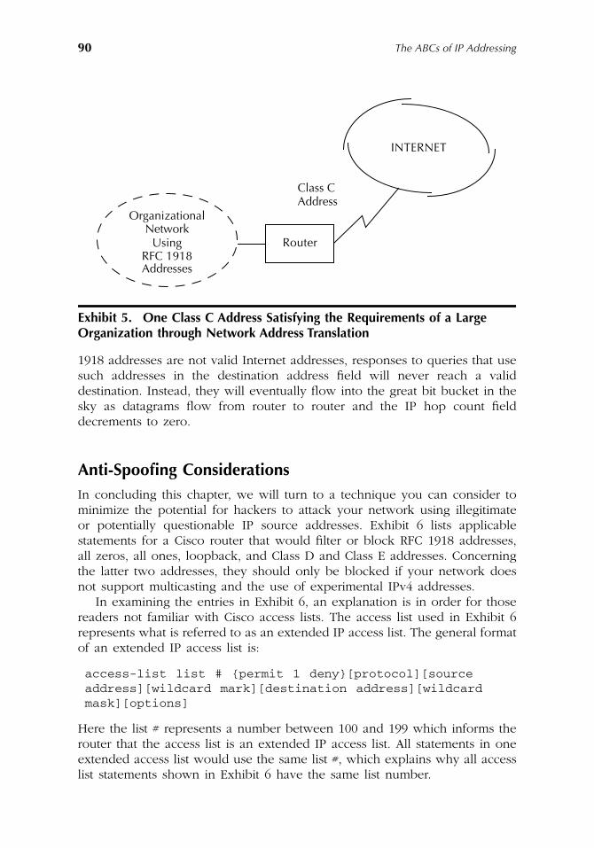
90
The ABCs of IP Addressing
1918 addresses are not valid Internet addresses, responses to queries that usesuch addresses in the destination address field will never reach a validdestination. Instead, they will eventually flow into the great bit bucket in thesky as datagrams flow from router to router and the IP hop count fielddecrements to zero.
Anti-Spoofing Considerations
In concluding this chapter, we will turn to a technique you can consider tominimize the potential for hackers to attack your network using illegitimateor potentially questionable IP source addresses. Exhibit 6 lists applicablestatements for a Cisco router that would filter or block RFC 1918 addresses,all zeros, all ones, loopback, and Class D and Class E addresses. Concerningthe latter two addresses, they should only be blocked if your network doesnot support multicasting and the use of experimental IPv4 addresses.
In examining the entries in Exhibit 6, an explanation is in order for thosereaders not familiar with Cisco access lists. The access list used in Exhibit 6represents what is referred to as an extended IP access list. The general formatof an extended IP access list is:
access-list list # {permit 1 deny}[protocol][source address][wildcard mark][destination address][wildcard mask][options]
Here the list # represents a number between 100 and 199 which informs therouter that the access list is an extended IP access list. All statements in oneextended access list would use the same list #, which explains why all accesslist statements shown in Exhibit 6 have the same list number.
Exhibit 5. One Class C Address Satisfying the Requirements of a Large Organization through Network Address Translation
INTERNET
Router
OrganizationalNetwork
UsingRFC 1918Addresses
Class CAddress
AU1144_ch04_fm Page 90 Thursday, October 11, 2001 1:26 PM
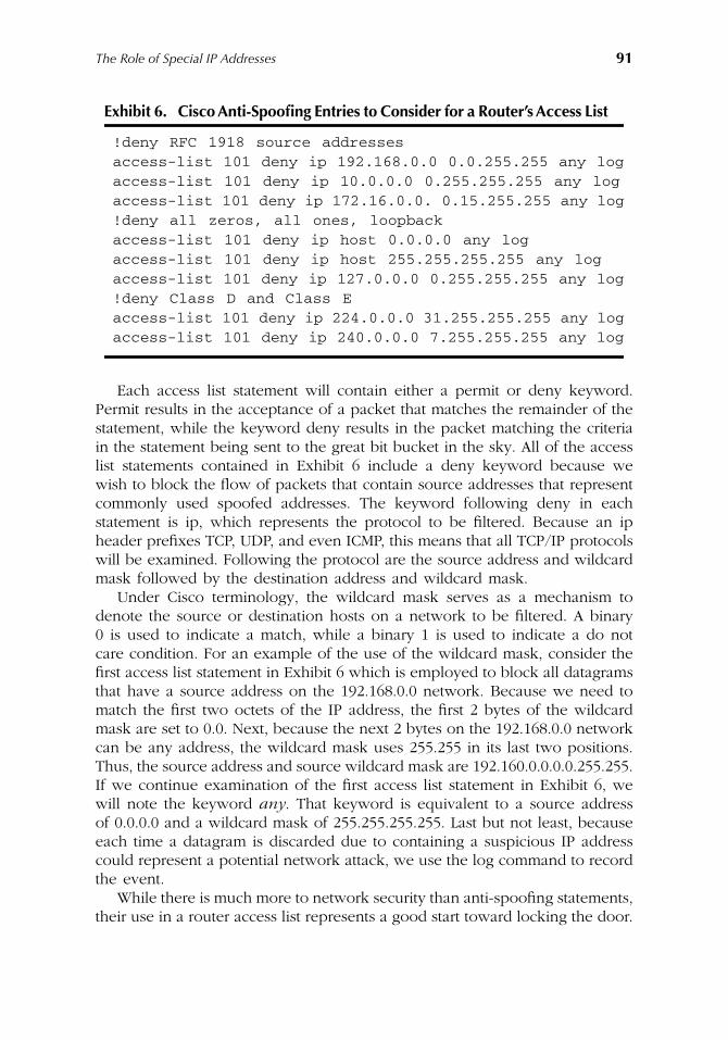
The Role of Special IP Addresses
91
Each access list statement will contain either a permit or deny keyword.Permit results in the acceptance of a packet that matches the remainder of thestatement, while the keyword deny results in the packet matching the criteriain the statement being sent to the great bit bucket in the sky. All of the accesslist statements contained in Exhibit 6 include a deny keyword because wewish to block the flow of packets that contain source addresses that representcommonly used spoofed addresses. The keyword following deny in eachstatement is ip, which represents the protocol to be filtered. Because an ipheader prefixes TCP, UDP, and even ICMP, this means that all TCP/IP protocolswill be examined. Following the protocol are the source address and wildcardmask followed by the destination address and wildcard mask.
Under Cisco terminology, the wildcard mask serves as a mechanism todenote the source or destination hosts on a network to be filtered. A binary0 is used to indicate a match, while a binary 1 is used to indicate a do notcare condition. For an example of the use of the wildcard mask, consider thefirst access list statement in Exhibit 6 which is employed to block all datagramsthat have a source address on the 192.168.0.0 network. Because we need tomatch the first two octets of the IP address, the first 2 bytes of the wildcardmask are set to 0.0. Next, because the next 2 bytes on the 192.168.0.0 networkcan be any address, the wildcard mask uses 255.255 in its last two positions.Thus, the source address and source wildcard mask are 192.160.0.0.0.0.255.255.If we continue examination of the first access list statement in Exhibit 6, wewill note the keyword
any
. That keyword is equivalent to a source addressof 0.0.0.0 and a wildcard mask of 255.255.255.255. Last but not least, becauseeach time a datagram is discarded due to containing a suspicious IP addresscould represent a potential network attack, we use the log command to recordthe event.
While there is much more to network security than anti-spoofing statements,their use in a router access list represents a good start toward locking the door.
Exhibit 6. Cisco Anti-Spoofing Entries to Consider for a Router’s Access List
!deny RFC 1918 source addressesaccess-list 101 deny ip 192.168.0.0 0.0.255.255 any logaccess-list 101 deny ip 10.0.0.0 0.255.255.255 any logaccess-list 101 deny ip 172.16.0.0. 0.15.255.255 any log!deny all zeros, all ones, loopbackaccess-list 101 deny ip host 0.0.0.0 any logaccess-list 101 deny ip host 255.255.255.255 any logaccess-list 101 deny ip 127.0.0.0 0.255.255.255 any log!deny Class D and Class Eaccess-list 101 deny ip 224.0.0.0 31.255.255.255 any logaccess-list 101 deny ip 240.0.0.0 7.255.255.255 any log
AU1144_ch04_fm Page 91 Thursday, October 11, 2001 1:26 PM

AU1144_ch04_fm Page 92 Thursday, October 11, 2001 1:26 PM
93
Chapter 5
Subnetting
Chapter 5 will focus on the subdivision of the two-level hierarchy associatedwith Class A, B, and C networks into a three-level hierarchy. This subdivisionis referred to as subnetting. It provides a considerable degree of IP addressingflexibility for network administrators. In discussing subnetting we will firstexamine the rationale behind the concept. Once this is accomplished, we willturn to the manner by which subnetting occurs, the use of the subnet mark,how subnetting can be used by organizations, and the manner by whichdifferent network devices can be configured to support a three-level hierarchy.
Rationale
Through the mid-1980s, the gradual growth in the use of the Internet resultedin several IP addressing-related problems. Those problems included the wasteof address space that could occur when multiple networks within an organi-zation are assigned individual IP addresses, the size of router tables, and thepotential management nightmare resulting from attempting to administer aClass A or Class B network as a single entity. As we will shortly note, eachof these problems was a driving force for a mechanism to break networksinto smaller entities referred to as subnets.
Waste of IP Address Space
One of the problems associated with the use of IP addresses was the originalnecessity to assign a distinct network address to each network. This methodof address assignment could result in the waste of many addresses. Becausethere are only a finite number of IPv4 addresses, it became recognized thata mechanism to permit a more efficient use of IP addresses was required.
AU1144_ch05_fm Page 93 Thursday, October 11, 2001 1:27 PM
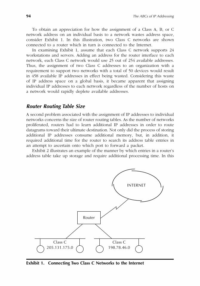
94
The ABCs of IP Addressing
To obtain an appreciation for how the assignment of a Class A, B, or Cnetwork address on an individual basis to a network wastes address space,consider Exhibit 1. In this illustration, two Class C networks are shownconnected to a router which in turn is connected to the Internet.
In examining Exhibit 1, assume that each Class C network supports 24workstations and servers. Adding an address for the router interface to eachnetwork, each Class C network would use 25 out of 254 available addresses.Thus, the assignment of two Class C addresses to an organization with arequirement to support two networks with a total of 50 devices would resultin 458 available IP addresses in effect being wasted. Considering this wasteof IP address space on a global basis, it became apparent that assigningindividual IP addresses to each network regardless of the number of hosts ona network would rapidly deplete available addresses.
Router Routing Table Size
A second problem associated with the assignment of IP addresses to individualnetworks concerns the size of router routing tables. As the number of networksproliferated, routers had to learn additional IP addresses in order to routedatagrams toward their ultimate destination. Not only did the process of storingadditional IP addresses consume additional memory, but, in addition, itrequired additional time for the router to search its address table entries inan attempt to ascertain onto which port to forward a packet.
Exhibit 2 illustrates an example of the manner by which entries in a router’saddress table take up storage and require additional processing time. In this
Exhibit 1. Connecting Two Class C Networks to the Internet
INTERNET
Router
Class C205.131.175.0
Class C198.78.46.0
AU1144_ch05_fm Page 94 Thursday, October 11, 2001 1:27 PM
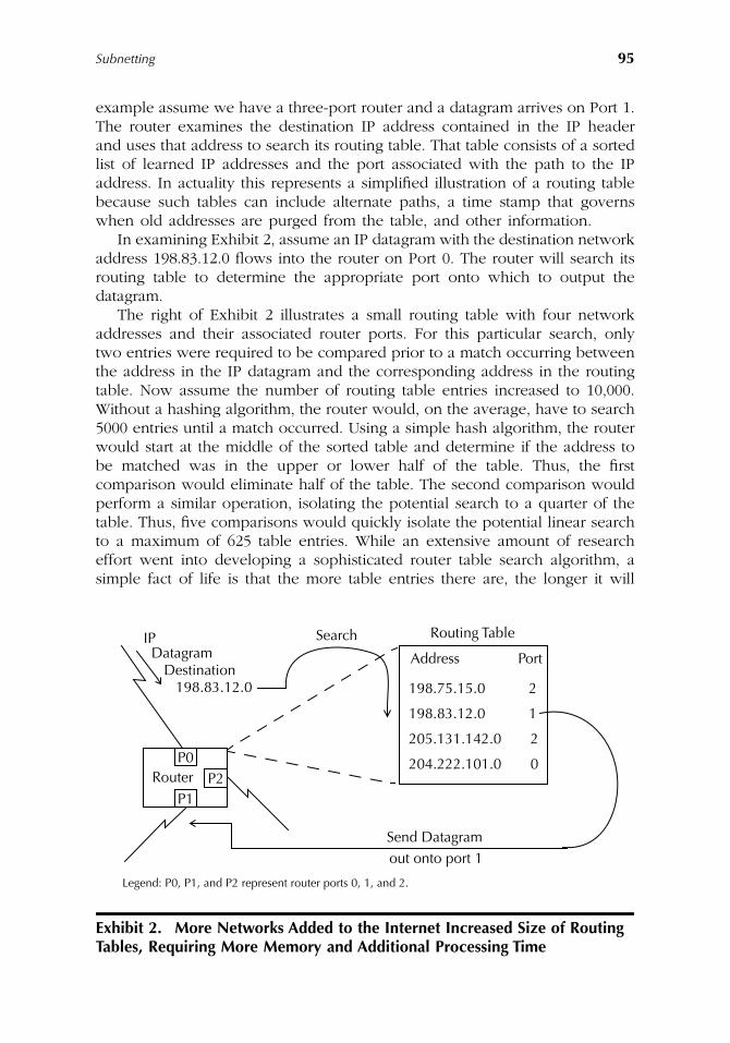
Subnetting
95
example assume we have a three-port router and a datagram arrives on Port 1.The router examines the destination IP address contained in the IP headerand uses that address to search its routing table. That table consists of a sortedlist of learned IP addresses and the port associated with the path to the IPaddress. In actuality this represents a simplified illustration of a routing tablebecause such tables can include alternate paths, a time stamp that governswhen old addresses are purged from the table, and other information.
In examining Exhibit 2, assume an IP datagram with the destination networkaddress 198.83.12.0 flows into the router on Port 0. The router will search itsrouting table to determine the appropriate port onto which to output thedatagram.
The right of Exhibit 2 illustrates a small routing table with four networkaddresses and their associated router ports. For this particular search, onlytwo entries were required to be compared prior to a match occurring betweenthe address in the IP datagram and the corresponding address in the routingtable. Now assume the number of routing table entries increased to 10,000.Without a hashing algorithm, the router would, on the average, have to search5000 entries until a match occurred. Using a simple hash algorithm, the routerwould start at the middle of the sorted table and determine if the address tobe matched was in the upper or lower half of the table. Thus, the firstcomparison would eliminate half of the table. The second comparison wouldperform a similar operation, isolating the potential search to a quarter of thetable. Thus, five comparisons would quickly isolate the potential linear searchto a maximum of 625 table entries. While an extensive amount of researcheffort went into developing a sophisticated router table search algorithm, asimple fact of life is that the more table entries there are, the longer it will
Exhibit 2. More Networks Added to the Internet Increased Size of Routing Tables, Requiring More Memory and Additional Processing Time
Routing Table
Address Port
198.75.15.0 2
198.83.12.0 1
205.131.142.0 2
204.222.101.0 0
SearchIPDatagram
Destination198.83.12.0
RouterP0
P1P2
Send Datagramout onto port 1
Legend: P0, P1, and P2 represent router ports 0, 1, and 2.
AU1144_ch05_fm Page 95 Thursday, October 11, 2001 1:27 PM
96
The ABCs of IP Addressing
take to locate a particular entry. Thus, additional router table entries bothconsume memory and result in additional processing time.
Management and Performance
A third problem which is primarily associated with using a Class A or ClassB address “as is” is management, with a related problem being the performancelevel of the network. For example, without a subdivision capability, you couldhave 16,777,214 hosts on a Class A network, while a Class B network couldhave up to 65,534 hosts. Even if you have a staff of helpful personnel tomanage a network that can consist of tens of thousands to tens of millionsof hosts, just think about the level of performance of an entity of either ofthose magnitudes. By permitting the subdivision of large networks into smallerentities, you achieve the ability to either directly manage groups of smallernetworks or assign such tasks to departments within an organization thatbecomes responsible for managing their portion of the network. In addition,because network traffic now flows over many essentially autonomous networksinstead of a single network, this subdivision can be expected to relievecongestion by isolating traffic that does not need to be routed to differentsubnets, i.e., traffic on a subnet destined to a server on that subnet remainson that network and only affects the transmission capability of other stationson that subnet. In comparison, if no subnets existed, then each transmissionwould affect every workstation on the larger network.
While management and performance issues are normally related to ClassA and Class B networks, it is also possible to encounter such problems on aClass C network. Thus, subnetting represents a technique to resolve manage-ment and performance problems across all three types of class networks.
RFC 950
Recognizing the previously described problems resulted in RFC 950 beingissued in 1985. Entitled Internet Standard Subnetting Procedure, this RFCdescribes in detail the procedure required to divide or subnet a single ClassA, B, or C network into subnetworks. Thus, we will turn attention to theprimary focus of this chapter to obtain an appreciation for the manner bywhich subnets are created and employed as well as how their utilizationfacilitates network management, permits a reduction in the size of routingtables, minimizes the waste of IP address space, and can result in an enhancedlevel of network performance. From the preceding you might obtain theimpression that subnetting is equivalent to raising the flag on July 4 and eatingapple pie. As we will shortly note, while subnetting might not be that patriotic,in a networking environment, its use is as common as either of the twoactivities mentioned for Independence Day.
AU1144_ch05_fm Page 96 Thursday, October 11, 2001 1:27 PM
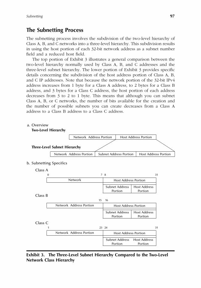
Subnetting
97
The Subnetting Process
The subnetting process involves the subdivision of the two-level hierarchy ofClass A, B, and C networks into a three-level hierarchy. This subdivision resultsin using the host portion of each 32-bit network address as a subnet numberfield and a reduced host field.
The top portion of Exhibit 3 illustrates a general comparison between thetwo-level hierarchy normally used by Class A, B, and C addresses and thethree-level subnet hierarchy. The lower portion of Exhibit 3 provides specificdetails concerning the subdivision of the host address portion of Class A, B,and C IP addresses. Note that because the network portion of the 32-bit IPv4address increases from 1 byte for a Class A address, to 2 bytes for a Class Baddress, and 3 bytes for a Class C address, the host portion of each addressdecreases from 3 to 2 to 1 byte. This means that although you can subnetClass A, B, or C networks, the number of bits available for the creation andthe number of possible subnets you can create decreases from a Class Aaddress to a Class B address to a Class C address.
Exhibit 3. The Three-Level Subnet Hierarchy Compared to the Two-Level Network Class Hierarchy
a. OverviewTwo-Level Hierarchy
Network Address Portion Host Address Portion
Three-Level Subnet Hierarchy
Network Address Portion Subnet Address Portion Host Address Portion
b. Subnetting Specifics
Class A0 7 8 31
Network Host Address Portion
Subnet Address Host AddressPortion Portion
Class B15 16
Network Address Portion Host Address Portion
Subnet Address Host AddressPortion Portion
Class C1 23 24 31
Network Address Portion Host Address Portion
Subnet Address Host AddressPortion Portion
AU1144_ch05_fm Page 97 Thursday, October 11, 2001 1:27 PM
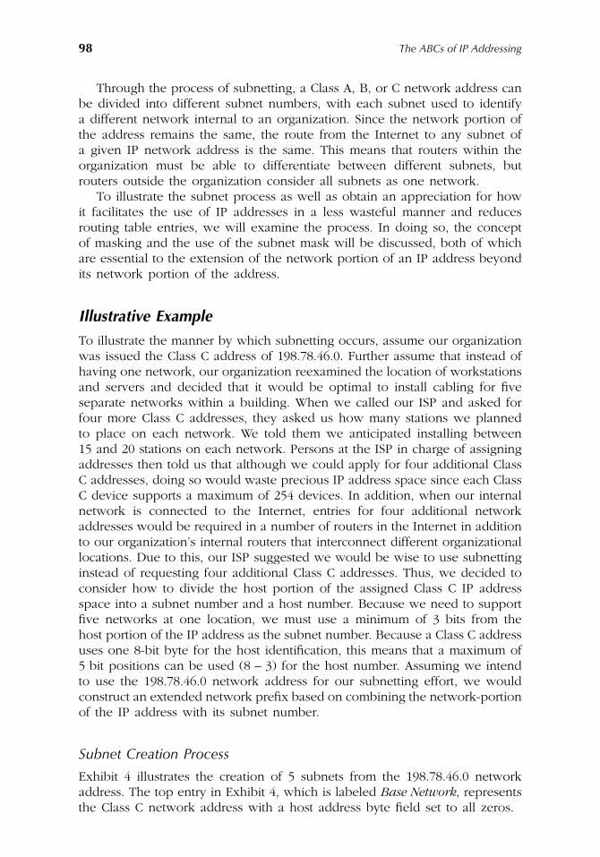
98
The ABCs of IP Addressing
Through the process of subnetting, a Class A, B, or C network address canbe divided into different subnet numbers, with each subnet used to identifya different network internal to an organization. Since the network portion ofthe address remains the same, the route from the Internet to any subnet ofa given IP network address is the same. This means that routers within theorganization must be able to differentiate between different subnets, butrouters outside the organization consider all subnets as one network.
To illustrate the subnet process as well as obtain an appreciation for howit facilitates the use of IP addresses in a less wasteful manner and reducesrouting table entries, we will examine the process. In doing so, the conceptof masking and the use of the subnet mask will be discussed, both of whichare essential to the extension of the network portion of an IP address beyondits network portion of the address.
Illustrative Example
To illustrate the manner by which subnetting occurs, assume our organizationwas issued the Class C address of 198.78.46.0. Further assume that instead ofhaving one network, our organization reexamined the location of workstationsand servers and decided that it would be optimal to install cabling for fiveseparate networks within a building. When we called our ISP and asked forfour more Class C addresses, they asked us how many stations we plannedto place on each network. We told them we anticipated installing between15 and 20 stations on each network. Persons at the ISP in charge of assigningaddresses then told us that although we could apply for four additional ClassC addresses, doing so would waste precious IP address space since each ClassC device supports a maximum of 254 devices. In addition, when our internalnetwork is connected to the Internet, entries for four additional networkaddresses would be required in a number of routers in the Internet in additionto our organization’s internal routers that interconnect different organizationallocations. Due to this, our ISP suggested we would be wise to use subnettinginstead of requesting four additional Class C addresses. Thus, we decided toconsider how to divide the host portion of the assigned Class C IP addressspace into a subnet number and a host number. Because we need to supportfive networks at one location, we must use a minimum of 3 bits from thehost portion of the IP address as the subnet number. Because a Class C addressuses one 8-bit byte for the host identification, this means that a maximum of5 bit positions can be used (8 – 3) for the host number. Assuming we intendto use the 198.78.46.0 network address for our subnetting effort, we wouldconstruct an extended network prefix based on combining the network-portionof the IP address with its subnet number.
Subnet Creation Process
Exhibit 4 illustrates the creation of 5 subnets from the 198.78.46.0 networkaddress. The top entry in Exhibit 4, which is labeled
Base Network
, representsthe Class C network address with a host address byte field set to all zeros.
AU1144_ch05_fm Page 98 Thursday, October 11, 2001 1:27 PM
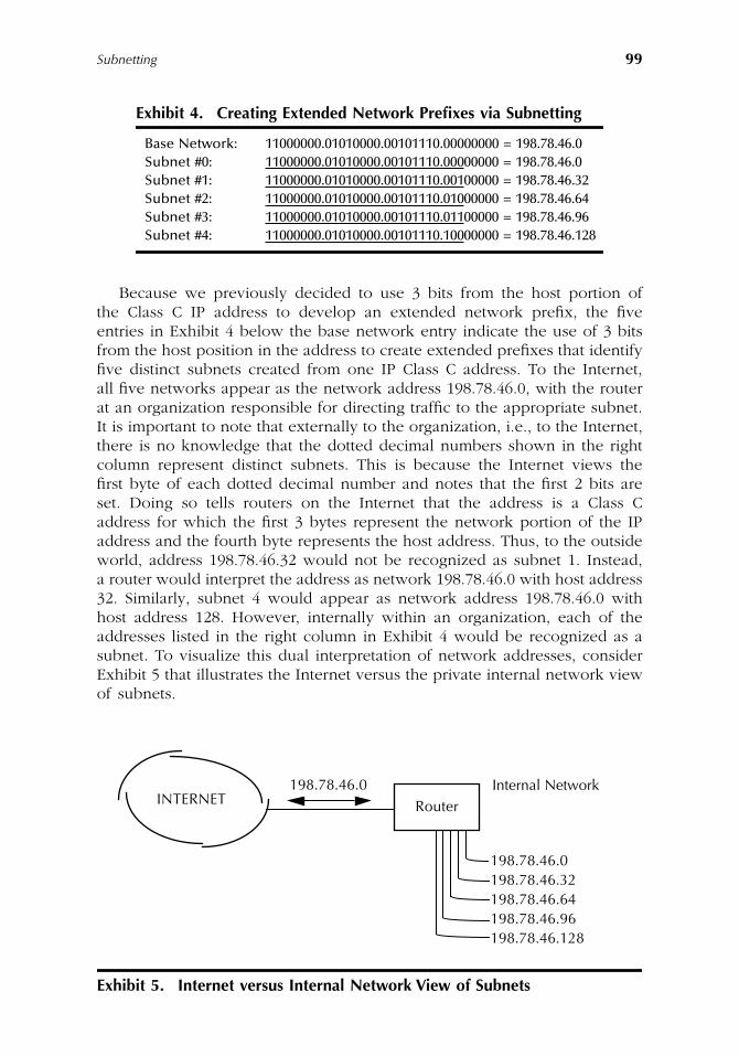
Subnetting
99
Because we previously decided to use 3 bits from the host portion ofthe Class C IP address to develop an extended network prefix, the fiveentries in Exhibit 4 below the base network entry indicate the use of 3 bitsfrom the host position in the address to create extended prefixes that identifyfive distinct subnets created from one IP Class C address. To the Internet,all five networks appear as the network address 198.78.46.0, with the routerat an organization responsible for directing traffic to the appropriate subnet.It is important to note that externally to the organization, i.e., to the Internet,there is no knowledge that the dotted decimal numbers shown in the rightcolumn represent distinct subnets. This is because the Internet views thefirst byte of each dotted decimal number and notes that the first 2 bits areset. Doing so tells routers on the Internet that the address is a Class Caddress for which the first 3 bytes represent the network portion of the IPaddress and the fourth byte represents the host address. Thus, to the outsideworld, address 198.78.46.32 would not be recognized as subnet 1. Instead,a router would interpret the address as network 198.78.46.0 with host address32. Similarly, subnet 4 would appear as network address 198.78.46.0 withhost address 128. However, internally within an organization, each of theaddresses listed in the right column in Exhibit 4 would be recognized as asubnet. To visualize this dual interpretation of network addresses, considerExhibit 5 that illustrates the Internet versus the private internal network viewof subnets.
Exhibit 4. Creating Extended Network Prefixes via Subnetting
Base Network: 11000000.01010000.00101110.00000000 = 198.78.46.0Subnet #0: 11000000.01010000.00101110.00000000 = 198.78.46.0Subnet #1: 11000000.01010000.00101110.00100000 = 198.78.46.32Subnet #2: 11000000.01010000.00101110.01000000 = 198.78.46.64Subnet #3: 11000000.01010000.00101110.01100000 = 198.78.46.96Subnet #4: 11000000.01010000.00101110.10000000 = 198.78.46.128
Exhibit 5. Internet versus Internal Network View of Subnets
INTERNET Router198.78.46.0 Internal Network
198.78.46.0198.78.46.32198.78.46.64198.78.46.96198.78.46.128
AU1144_ch05_fm Page 99 Thursday, October 11, 2001 1:27 PM
100
The ABCs of IP Addressing
External View
Exhibit 5 illustrates the manner by which traffic flowing from the Internet tothe internal organizational network is viewed, i.e., each IP datagram destinedto the 198.78.46.0 network is first routed toward the organizational networkconnected to the router. Even though that router is shown as being connectedto 5 subnets, to traffic on the Internet side of the router, there is no knowledgeof the existence of a subnet structure. Thus, routers on the Internet only haveto maintain one network address that permits simpler routing tables to bemaintained.
As we might logically assume from our prior discussion of Class C addresses,any address with the network prefix 198.78.46.0 will be routed to the corporaterouter. However, although we noted how subnet addresses are formed, wehave yet to discuss how we assign host addresses to devices connected todifferent subnets, or how the router can break down a subnet address so itcan correctly route traffic to an appropriate subnet. We will now turn ourattention to these topics.
Host Addresses on Subnets
We previously subdivided the host portion of a Class C address into a 3-bitsubnet field and a 5-bit host field. When we consider the number of hostswe can assign to a subnet, we must consider two restrictions, referred to asthe all-0s subnet and the all-1s subnet. When subnetting was originally definedin RFC 950, it prohibited the use of the all-0s and the all-1s subnets. Therationale for prohibiting the use of an all-0s subnet was to alleviate the situationwhere a classful router could become confused. Here the term classful rep-resents any IP address that is subdivided into a network and host field. Thus,classful references Class A, B, and C IPv4 addresses.
To appreciate the manner by which a classful router can become confused,let us first digress a bit and review the term
prefix-length
, which representsanother method of indicating the network portion of a classful address. Theprefix-length is a number that identifies the length of the network portion ofan IP address or extended network portion of an IP address. The use of aprefix-length includes a forward slash (/) that prefixes the prefix-length. Forexample, a conventional Class C network address would be written as followsto indicate that the network was 24 bits in length: 2.x.y.z/24, where w, x, y,and z represent the dotted decimal digits of a Class C address.
Let us return to the manner by which a classful router could becomeconfused by the use of an all-0s subnet, a route to an all-0s subnet, and a routeto the entire network. Unfortunately certain routing protocols, such as RIP-1,do not provide a mask or prefix-length with each route. When this occurs, therouting advertisements, for example, for the network 205.131.175.0/24 and itszero subnet, 205.131.175.0/27, are exactly the same, i.e., both the networkand the subnet have the identical address of 205.131.175.0. Thus, unless therouter knows the prefix-length or mask, it cannot tell the difference betweena route to the all-0s subnet and the route to the entire network.
AU1144_ch05_fm Page 100 Thursday, October 11, 2001 1:27 PM
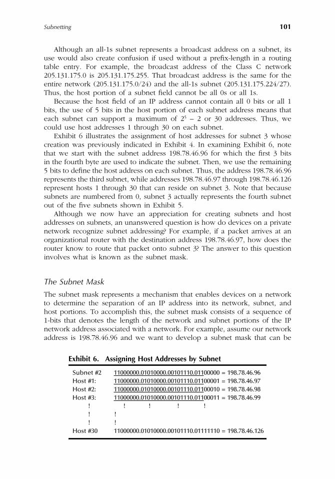
Subnetting
101
Although an all-1s subnet represents a broadcast address on a subnet, itsuse would also create confusion if used without a prefix-length in a routingtable entry. For example, the broadcast address of the Class C network205.131.175.0 is 205.131.175.255. That broadcast address is the same for theentire network (205.131.175.0/24) and the all-1s subnet (205.131.175.224/27).Thus, the host portion of a subnet field cannot be all 0s or all 1s.
Because the host field of an IP address cannot contain all 0 bits or all 1bits, the use of 5 bits in the host portion of each subnet address means thateach subnet can support a maximum of 2
5
– 2 or 30 addresses. Thus, wecould use host addresses 1 through 30 on each subnet.
Exhibit 6 illustrates the assignment of host addresses for subnet 3 whosecreation was previously indicated in Exhibit 4. In examining Exhibit 6, notethat we start with the subnet address 198.78.46.96 for which the first 3 bitsin the fourth byte are used to indicate the subnet. Then, we use the remaining5 bits to define the host address on each subnet. Thus, the address 198.78.46.96represents the third subnet, while addresses 198.78.46.97 through 198.78.46.126represent hosts 1 through 30 that can reside on subnet 3. Note that becausesubnets are numbered from 0, subnet 3 actually represents the fourth subnetout of the five subnets shown in Exhibit 5.
Although we now have an appreciation for creating subnets and hostaddresses on subnets, an unanswered question is how do devices on a privatenetwork recognize subnet addressing? For example, if a packet arrives at anorganizational router with the destination address 198.78.46.97, how does therouter know to route that packet onto subnet 3? The answer to this questioninvolves what is known as the subnet mask.
The Subnet Mask
The subnet mask represents a mechanism that enables devices on a networkto determine the separation of an IP address into its network, subnet, andhost portions. To accomplish this, the subnet mask consists of a sequence of1-bits that denotes the length of the network and subnet portions of the IPnetwork address associated with a network. For example, assume our networkaddress is 198.78.46.96 and we want to develop a subnet mask that can be
Exhibit 6. Assigning Host Addresses by Subnet
Subnet #2 11000000.01010000.00101110.01100000 = 198.78.46.96Host #1: 11000000.01010000.00101110.01100001 = 198.78.46.97Host #2: 11000000.01010000.00101110.01100010 = 198.78.46.98Host #3: 11000000.01010000.00101110.01100011 = 198.78.46.99
! ! ! ! !! !! !
Host #30 11000000.01010000.00101110.01111110 = 198.78.46.126
AU1144_ch05_fm Page 101 Thursday, October 11, 2001 1:27 PM
102
The ABCs of IP Addressing
used to identify the extended network. Because we previously used 3 bitsfrom the host portion of the IP address, the subnet mask would become:
11111111.11111111.11111111.11100000
Similar to the manner by which IP addresses can be expressed using dotted-decimal notation, we can also express subnet masks using that notation. Doingso, we can express the subnet mask as:
255.255.255.224
The subnet mask tells the device examining an IP address that bits in theaddress should be treated as the extended network address consisting ofnetwork and subnet addresses. Then, the remaining bits that are not set inthe mask indicate the host of the extended network address. However, howdoes a device determine the subnet of the destination address? Because thesubnet mask indicates the length of the extended network to include thenetwork and subnet fields, knowing the length of the network portion of theaddress provides a device with the ability to determine the number of bits inthe subnet field. Once this is accomplished, the device can determine thevalue of those bits, which indicates the subnet. To illustrate this concept, usethe IP address 198.78.46.97 and the subnet mask 255.255.255.224, with thelatter used to define a 27-bit extended network. The relationship between theIP address and the subnet mask is shown below:
In examining the above IP address and subnet mask, note that the first 2 bitsin the IP address are set. This indicates a Class C address. Because a Class Caddress consists of 3 bytes used for the network address and 1 byte for thehost address, this also means the subnet must be 3 bits in length (27 – 24).Thus, bits 25 through 27, which are set to 011 in the IP address, identify thesubnet as subnet 3. Because the last 5 bits in the subnet mask are set to zero,this means that those bit positions in the IP address identify the host onsubnet 3. Because those bits have the value 00001, this means the IP addressreferences host 1 on subnet 3 on network 198.78.46.0.
Configuration Examples
When configuring a workstation or server to operate on a TCP/IP network,most network operating systems require you to enter a minimum of three IPaddresses and an optional subnet mask or mask bit setting. The three IPaddresses include the IP address assigned to the workstation or server, theIP address of the gateway or router which is responsible for relaying packetswith a destination that is not on the local network to a different network,and a name resolver which, as previously noted in Chapter 4, is also referred
IP Address: 198.78.46.97 11000000.01010000.00101110.01100001Subnet Mask: 255.255.255.244 11111111.11111111.11111111.11100000
AU1144_ch05_fm Page 102 Thursday, October 11, 2001 1:27 PM
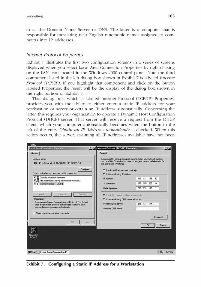
Subnetting
103
to as the Domain Name Server or DNS. The latter is a computer that isresponsible for translating near English mnemonic names assigned to com-puters into IP addresses.
Internet Protocol Properties
Exhibit 7 illustrates the first two configuration screens in a series of screensdisplayed when you select Local Area Connection Properties by right clickingon the LAN icon located in the Windows 2000 control panel. Note the thirdcomponent listed in the left dialog box shown in Exhibit 7 is labeled
InternetProtocol (TCP/IP)
. If you highlight that component and click on the buttonlabeled Properties, the result will be the display of the dialog box shown inthe right portion of Exhibit 7.
That dialog box, which is labeled Internet Protocol (TCP/IP) Properties,provides you with the ability to either enter a static IP address for yourworkstation or server or obtain an IP address automatically. Concerning thelatter, this requires your organization to operate a Dynamic Host ConfigurationProtocol (DHCP) server. That server will receive a request from the DHCPclient, which your computer automatically becomes when the button to theleft of the entry
Obtain an IP Address Automatically
is checked. When thisaction occurs, the server, assuming all IP addresses available have not been
Exhibit 7. Configuring a Static IP Address for a Workstation
AU1144_ch05_fm Page 103 Thursday, October 11, 2001 1:27 PM
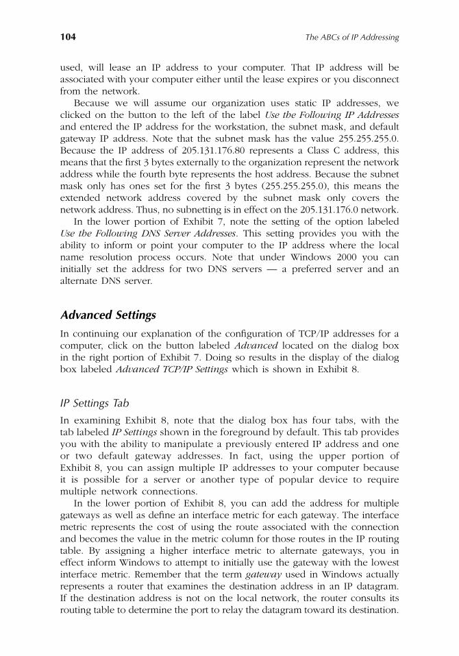
104
The ABCs of IP Addressing
used, will lease an IP address to your computer. That IP address will beassociated with your computer either until the lease expires or you disconnectfrom the network.
Because we will assume our organization uses static IP addresses, weclicked on the button to the left of the label
Use the Following IP Addresses
and entered the IP address for the workstation, the subnet mask, and defaultgateway IP address. Note that the subnet mask has the value 255.255.255.0.Because the IP address of 205.131.176.80 represents a Class C address, thismeans that the first 3 bytes externally to the organization represent the networkaddress while the fourth byte represents the host address. Because the subnetmask only has ones set for the first 3 bytes (255.255.255.0), this means theextended network address covered by the subnet mask only covers thenetwork address. Thus, no subnetting is in effect on the 205.131.176.0 network.
In the lower portion of Exhibit 7, note the setting of the option labeled
Use the Following DNS Server Addresses
. This setting provides you with theability to inform or point your computer to the IP address where the localname resolution process occurs. Note that under Windows 2000 you caninitially set the address for two DNS servers — a preferred server and analternate DNS server.
Advanced Settings
In continuing our explanation of the configuration of TCP/IP addresses for acomputer, click on the button labeled
Advanced
located on the dialog boxin the right portion of Exhibit 7. Doing so results in the display of the dialogbox labeled
Advanced TCP/IP Settings
which is shown in Exhibit 8.
IP Settings Tab
In examining Exhibit 8, note that the dialog box has four tabs, with thetab labeled
IP Settings
shown in the foreground by default. This tab providesyou with the ability to manipulate a previously entered IP address and oneor two default gateway addresses. In fact, using the upper portion ofExhibit 8, you can assign multiple IP addresses to your computer becauseit is possible for a server or another type of popular device to requiremultiple network connections.
In the lower portion of Exhibit 8, you can add the address for multiplegateways as well as define an interface metric for each gateway. The interfacemetric represents the cost of using the route associated with the connectionand becomes the value in the metric column for those routes in the IP routingtable. By assigning a higher interface metric to alternate gateways, you ineffect inform Windows to attempt to initially use the gateway with the lowestinterface metric. Remember that the term
gateway
used in Windows actuallyrepresents a router that examines the destination address in an IP datagram.If the destination address is not on the local network, the router consults itsrouting table to determine the port to relay the datagram toward its destination.
AU1144_ch05_fm Page 104 Thursday, October 11, 2001 1:27 PM
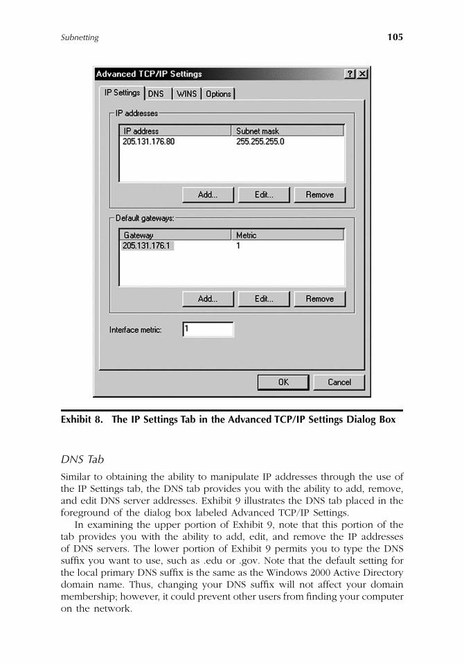
Subnetting
105
DNS Tab
Similar to obtaining the ability to manipulate IP addresses through the use ofthe IP Settings tab, the DNS tab provides you with the ability to add, remove,and edit DNS server addresses. Exhibit 9 illustrates the DNS tab placed in theforeground of the dialog box labeled Advanced TCP/IP Settings.
In examining the upper portion of Exhibit 9, note that this portion of thetab provides you with the ability to add, edit, and remove the IP addressesof DNS servers. The lower portion of Exhibit 9 permits you to type the DNSsuffix you want to use, such as .edu or .gov. Note that the default setting forthe local primary DNS suffix is the same as the Windows 2000 Active Directorydomain name. Thus, changing your DNS suffix will not affect your domainmembership; however, it could prevent other users from finding your computeron the network.
Exhibit 8. The IP Settings Tab in the Advanced TCP/IP Settings Dialog Box
AU1144_ch05_fm Page 105 Thursday, October 11, 2001 1:27 PM
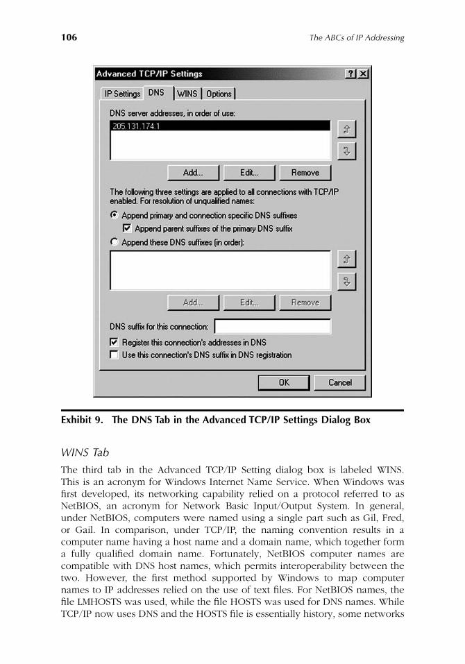
106
The ABCs of IP Addressing
WINS Tab
The third tab in the Advanced TCP/IP Setting dialog box is labeled WINS.This is an acronym for Windows Internet Name Service. When Windows wasfirst developed, its networking capability relied on a protocol referred to asNetBIOS, an acronym for Network Basic Input/Output System. In general,under NetBIOS, computers were named using a single part such as Gil, Fred,or Gail. In comparison, under TCP/IP, the naming convention results in acomputer name having a host name and a domain name, which together forma fully qualified domain name. Fortunately, NetBIOS computer names arecompatible with DNS host names, which permits interoperability between thetwo. However, the first method supported by Windows to map computernames to IP addresses relied on the use of text files. For NetBIOS names, thefile LMHOSTS was used, while the file HOSTS was used for DNS names. WhileTCP/IP now uses DNS and the HOSTS file is essentially history, some networks
Exhibit 9. The DNS Tab in the Advanced TCP/IP Settings Dialog Box
AU1144_ch05_fm Page 106 Thursday, October 11, 2001 1:27 PM
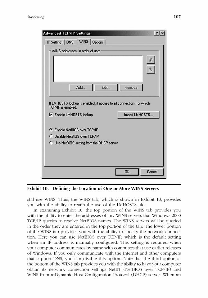
Subnetting
107
still use WINS. Thus, the WINS tab, which is shown in Exhibit 10, providesyou with the ability to retain the use of the LMHOSTS file.
In examining Exhibit 10, the top portion of the WINS tab provides youwith the ability to enter the addresses of any WINS servers that Windows 2000TCP/IP queries to resolve NetBIOS names. The WINS servers will be queriedin the order they are entered in the top portion of the tab. The lower portionof the WINS tab provides you with the ability to specify the network connec-tion. Here you can use NetBIOS over TCP/IP, which is the default settingwhen an IP address is manually configured. This setting is required whenyour computer communicates by name with computers that use earlier releasesof Windows. If you only communicate with the Internet and other computersthat support DNS, you can disable this option. Note that the third option atthe bottom of the WINS tab provides you with the ability to have your computerobtain its network connection settings NetBT (NetBIOS over TCP/IP) andWINS from a Dynamic Host Configuration Protocol (DHCP) server. When an
Exhibit 10. Defining the Location of One or More WINS Servers
AU1144_ch05_fm Page 107 Thursday, October 11, 2001 1:27 PM
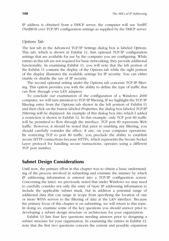
108
The ABCs of IP Addressing
IP address is obtained from a DHCP server, the computer will use NetBT(NetBIOS over TCP/IP) configuration settings as supplied by the DHCP server.
Options Tab
The last tab in the Advanced TCP/IP Settings dialog box is labeled
Options
.This tab, which is shown in Exhibit 11, lists optional TCP/IP configurationsettings that are available for use by the computer you are configuring. Whileentries in this tab are not required for basic networking, they provide additionalfunctionality. In examining Exhibit 11, you will note that the left portion ofthe Exhibit 11 contains the display of the Options tab while the right portionof the display illustrates the available settings for IP security. You can eitherenable or disable the use of IP security.
The second optional setting under the Options tab concerns TCP/IP filter-ing. This option provides you with the ability to define the type of traffic thatcan flow through your LAN adapters.
To conclude our examination of the configuration of a Windows 2000computer, we will turn attention to TCP/IP filtering. If we highlight the TCP/IPfiltering entry from the Options tab shown in the left portion of Exhibit 11and then click on the button labeled
Properties
,
the dialog box labeled
TCP/IPFiltering
will be displayed. An example of this dialog box into which I addeda restriction is shown in Exhibit 12. In this example, only TCP port 80 trafficwill be permitted to flow through the interface. TCP port 80 represents Webtraffic. However, it should be noted that prior to enabling any filtering, youshould carefully consider the effect, if any, on your computer operations.By restricting TCP to port 80 traffic, you preclude the ability to establishsecure HTTP connections because HTTPs, which represents the Secure SocketLayer protocol for handling secure transactions, operates using a differentTCP port number.
Subnet Design Considerations
Until now, the primary effort in this chapter was to obtain a basic understand-ing of the process involved in subnetting and examine the manner by whichIP addressing information is entered into a TCP/IP configuration screen.Concerning the latter, we previously noted that under Windows we may needto carefully consider not only the entry of basic IP addressing information toinclude the applicable subnet mask, but in addition a potential range ofadditional data that can range in scope from specifying the location of oneor more WINS servers to the filtering of data at the LAN interface. Becausethe primary focus of this chapter is on subnetting, we will return to this topic.In doing so, examine some of the key questions you should answer prior todeveloping a subnet design structure or architecture for your organization.
Exhibit 13 lists four key questions needing answers prior to designing asubnet structure for your organization. In examining the entries in Exhibit 13,note that the first two questions concern the current and possible expansion
AU1144_ch05_fm Page 108 Thursday, October 11, 2001 1:27 PM
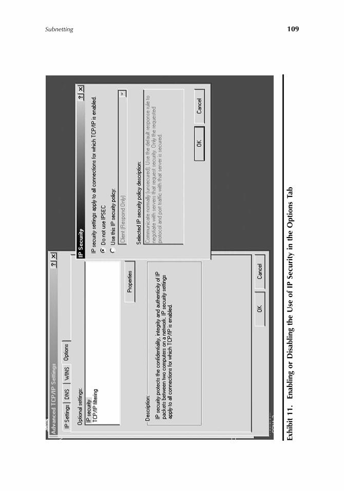
Subnetting
109
Exhi
bit
11.
Enab
ling
or D
isab
ling
the
Use
of
IP S
ecur
ity
in t
he O
ptio
ns T
ab
AU1144_ch05_fm Page 109 Thursday, October 11, 2001 1:27 PM
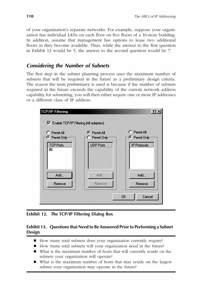
110
The ABCs of IP Addressing
of your organization’s separate networks. For example, suppose your organi-zation has individual LANs on each floor on five floors of a 16-story building.In addition, assume that management has options to lease two additionalfloors as they become available. Thus, while the answer to the first questionin Exhibit 13 would be 5, the answer to the second question would be 7.
Considering the Number of Subnets
The first step in the subnet planning process uses the maximum number ofsubnets that will be required in the future as a preliminary design criteria.The reason the term
preliminary
is used is because if the number of subnetsrequired in the future exceeds the capability of the current network addresscapability for subnetting, you will then either require one or more IP addressesor a different class of IP address.
Exhibit 12. The TCP/IP Filtering Dialog Box
Exhibit 13. Questions that Need to Be Answered Prior to Performing a Subnet
Design
�
How many total subnets does your organization currently require?
�
How many total subnets will your organization need in the future?
�
What is the maximum number of hosts that will currently reside on thesubnets your organization will operate?
�
What is the maximum number of hosts that may reside on the largestsubnet your organization may operate in the future?
AU1144_ch05_fm Page 110 Thursday, October 11, 2001 1:27 PM
Subnetting
111
Assume our organization will require 7 subnets. We would round thisnumber up to the nearest power of two. Thus, since 2
3
is 8, this means wewill require 3 bit positions to define the relevant subnets.
Host Considerations
Next, we need to consider the number of hosts that will reside on the largestsubnet today and in the future. We need to consider the maximum numberof hosts to determine if the reduced portion of the host address field issufficient in length to support the largest number of hosts that will be locatedon a subnet. For example, if we are working with a Class B address, the hostportion of that address is 2 bytes or 16 bits in length. In comparison, if weare working with a Class C address, the host portion of that address is 1 byteor 8 bits in length. Thus, if we need 7 subnets, this means we would use3 bit positions from the host field for subnetting, leaving 13 bits in a Class Baddress or 5 bits in a Class C address for the reduced host portion of theoriginal host field. If we assume that the largest subnet will have 30 hosts,we then need to determine the number of bits required to support 30 hosts.Because 2
5
– 2 is 30, we would then require 5 bit positions in the reducedhost field to support 30 hosts. Remember, the reason we subtract 2 is becausewe cannot use a subnet of all 0s or one of all 1s. Thus, for both a Class Band a Class C network we could easily accommodate up to 7 subnets withup to 30 hosts per subnet. If the largest number of hosts would exceed thenumber of available bit positions, you could either consider moving somehosts onto a different subnet or requesting another IP address. Prior toillustrating another example of subnetting, we will digress briefly and reviewin more detail another method used to reference address classes. This methodis referred to as the prefix method.
The Prefix Method of Address Reference
Remembering our discussion of classful addressing, we noted that a Class Aaddress has an 8-bit byte used for the network portion of the address. Similarly,a Class B address uses 16 bits for the network portion, while a Class C addressuses 24 bits. As noted earlier in this chapter, another method commonly usedto define the network portion of a classful IP address is via the use of aforward slash (/) character followed by a numeric that indicates the length ofthe network portion of the address. Thus, we can describe Class A, B, and Cnetworks as follows:
Class A address w.x.y.z/8
Class B address w.x.y.z/16
Class C address w.x.y.z/24
where w.x.y.z. represents applicable classful dotted decimal numbers. Notethat we can also apply the use of a prefix to the extended network portion
AU1144_ch05_fm Page 111 Thursday, October 11, 2001 1:27 PM
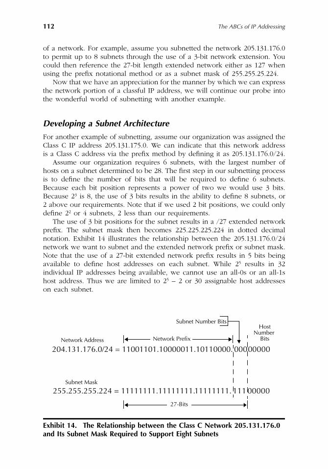
112
The ABCs of IP Addressing
of a network. For example, assume you subnetted the network 205.131.176.0to permit up to 8 subnets through the use of a 3-bit network extension. Youcould then reference the 27-bit length extended network either as 127 whenusing the prefix notational method or as a subnet mask of 255.255.25.224.
Now that we have an appreciation for the manner by which we can expressthe network portion of a classful IP address, we will continue our probe intothe wonderful world of subnetting with another example.
Developing a Subnet Architecture
For another example of subnetting, assume our organization was assigned theClass C IP address 205.131.175.0. We can indicate that this network addressis a Class C address via the prefix method by defining it as 205.131.176.0/24.
Assume our organization requires 6 subnets, with the largest number ofhosts on a subnet determined to be 28. The first step in our subnetting processis to define the number of bits that will be required to define 6 subnets.Because each bit position represents a power of two we would use 3 bits.Because 2
3
is 8, the use of 3 bits results in the ability to define 8 subnets, or2 above our requirements. Note that if we used 2 bit positions, we could onlydefine 2
2
or 4 subnets, 2 less than our requirements.The use of 3 bit positions for the subnet results in a /27 extended network
prefix. The subnet mask then becomes 225.225.225.224 in dotted decimalnotation. Exhibit 14 illustrates the relationship between the 205.131.176.0/24network we want to subnet and the extended network prefix or subnet mask.Note that the use of a 27-bit extended network prefix results in 5 bits beingavailable to define host addresses on each subnet. While 25 results in 32individual IP addresses being available, we cannot use an all-0s or an all-1shost address. Thus we are limited to 25 – 2 or 30 assignable host addresseson each subnet.
Exhibit 14. The Relationship between the Class C Network 205.131.176.0 and Its Subnet Mask Required to Support Eight Subnets
Network Address
204.131.176.0/24 = 11001101.10000011.10110000. 00000000Network Prefix
Subnet Number Bits Host
Number Bits
Subnet Mask
255.255.255.224 = 11111111.11111111.11111111. 111 00000
27-Bits
AU1144_ch05_fm Page 112 Thursday, October 11, 2001 1:27 PM
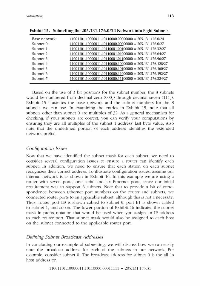
Subnetting 113
Based on the use of 3 bit positions for the subnet number, the 8 subnetswould be numbered from decimal zero (0002) through decimal seven (1112).Exhibit 15 illustrates the base network and the subnet numbers for the 8subnets we can use. In examining the entries in Exhibit 15, note that allsubnets other than subnet 0 are multiples of 32. As a general mechanism forchecking, if your subnets are correct, you can verify your computations byensuring they are all multiples of the subnet 1 address’ last byte value. Alsonote that the underlined portion of each address identifies the extendednetwork prefix.
Configuration Issues
Now that we have identified the subnet mask for each subnet, we need toconsider several configuration issues to ensure a router can identify eachsubnet. In addition, we need to ensure that each station on each subnetrecognizes their correct address. To illustrate configuration issues, assume ourinternal network is as shown in Exhibit 16. In this example we are using arouter with seven ports, one serial and six Ethernet ports, since our initialrequirement was to support 6 subnets. Note that to provide a bit of corre-spondence between Ethernet port numbers on the router and subnets, weconnected router ports to an applicable subnet, although this is not a necessity.Thus, router port E0 is shown cabled to subnet 0, port E1 is shown cabledto subnet 1, and so on. The lower portion of Exhibit 16 indicates the subnetmask in prefix notation that would be used when you assign an IP addressto each router port. That subnet mask would also be assigned to each hoston the subnet connected to the applicable router port.
Defining Subnet Broadcast Addresses
In concluding our example of subnetting, we will discuss how we can easilynote the broadcast address for each of the subnets in our network. Forexample, consider subnet 0. The broadcast address for subnet 0 is the all 1shost address or:
11001101.10000011.10110000.00011111 = 205.131.175.31
Exhibit 15. Subnetting the 205.131.176.0/24 Network into Eight Subnets
Base network: 11001101.10000011.10110000.00000000 = 205.131.176.0/24Subnet 0: 11001101.10000011.10110000.00000000 = 205.131.176.0/27Subnet 1: 11001101.10000011.10110001.00100000 = 205.131.176.32/27Subnet 2: 11001101.10000011.10110001.01000000 = 205.131.176.64/27Subnet 3: 11001101.10000011.10110001.01100000 = 205.131.176.96/27Subnet 4: 11001101.10000011.10110000.10000000 = 205.131.176.128/27Subnet 5: 11001101.10000011.10110000.10100000 = 205.131.176.160/27Subnet 6: 11001101.10000011.10110000.11000000 = 205.131.176.192/27Subnet 7: 11001101.10000011.10110000.11100000 = 205.131.176.224/27
AU1144_ch05_fm Page 113 Thursday, October 11, 2001 1:27 PM
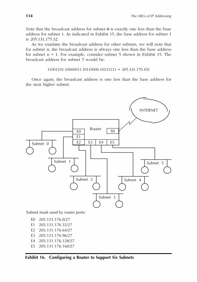
114 The ABCs of IP Addressing
Note that the broadcast address for subnet 0 is exactly one less than the baseaddress for subnet 1. As indicated in Exhibit 15, the base address for subnet 1is 205.131.175.32.
As we examine the broadcast address for other subnets, we will note thatfor subnet n, the broadcast address is always one less than the base addressfor subnet n + 1. For example, consider subnet 5 shown in Exhibit 15. Thebroadcast address for subnet 5 would be:
11001101.10000011.10110000.10111111 = 205.131.176.191
Once again, the broadcast address is one less than the base address forthe next higher subnet.
Exhibit 16. Configuring a Router to Support Six Subnets
INTERNET
Router
Subnet 0
Subnet mask used by router ports:
E3 E4 E5
S0E0
E2E1
Subnet 1
Subnet 2
Subnet 3
Subnet 4
Subnet 5
E0 205.131.176.0/27E1 205.131.176.32/27E2 205.131.176.64/27E3 205.131.176.96/27E4 205.131.176.128/27E5 205.131.176.160/27
AU1144_ch05_fm Page 114 Thursday, October 11, 2001 1:27 PM
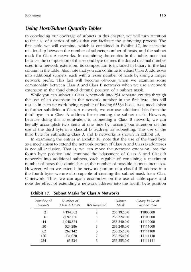
Subnetting 115
Using Host/Subnet Quantity Tables
In concluding our coverage of subnets in this chapter, we will turn attentionto the use of a series of tables that can facilitate the subnetting process. Thefirst table we will examine, which is contained in Exhibit 17, indicates therelationship between the number of subnets, number of hosts, and the subnetmask for Class A networks. In examining the entries in this table, note thatbecause the composition of the second byte defines the dotted decimal numberused in a network extension, its composition is included in binary in the lastcolumn in the table. Also note that you can continue to adjust Class A addressesinto additional subnets, each with a lesser number of hosts by using a longernetwork prefix. This fact will become obvious when we examine somecommonality between Class A and Class B networks when we use a networkextension in the third dotted decimal position of a subnet mask.
While you can subnet a Class A network into 254 separate entities throughthe use of an extension to the network number in the first byte, this stillresults in each network being capable of having 65534 hosts. As a mechanismto further subdivide a Class A network, we can use additional bits from thethird byte in a Class A address for extending the subnet mask. However,because doing this is equivalent to subnetting a Class B network, we canliterally accomplish two items at one time by focusing our attention on theuse of the third byte in a classful IP address for subnetting. This use of thethird byte for subnetting Class A and B networks is shown in Exhibit 18.
In examining the entries in Exhibit 18, note that the use of the third byteas a mechanism to extend the network portion of Class A and Class B addressesis not all inclusive. That is, we can move the network extension into thefourth byte position and continue the adjustment of Class A and Class Bnetworks into additional subnets, each capable of containing a maximumnumber of hosts that diminishes as the number of possible subnets increases.However, when we extend the network portion of a classful IP address intothe fourth byte, we are also capable of creating the subnet mask for a ClassC network. Thus, we can again economize on the use of table space andnote the effect of extending a network address into the fourth byte position
Exhibit 17. Subnet Masks for Class A Networks
Number of Subnets
Number of Class A Hosts Bits Required
Subnet Mask
Binary Value of Second Byte
2 4,194,302 2 255.192.0.0 110000006 2,097,150 3 255.224.0.0 11100000
14 1,048,574 4 255.240.0.0 1111000030 524,286 5 255.248.0.0 1111100062 262,142 6 255.252.0.0 11111100
126 131,070 7 255.254.0.0 11111110254 65,534 8 255.255.0.0 11111111
AU1144_ch05_fm Page 115 Thursday, October 11, 2001 1:27 PM
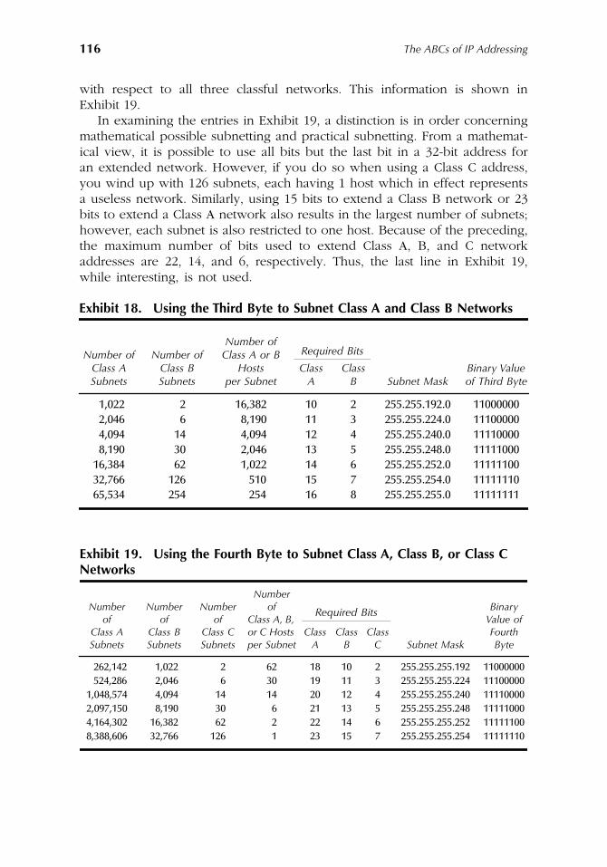
116 The ABCs of IP Addressing
with respect to all three classful networks. This information is shown inExhibit 19.
In examining the entries in Exhibit 19, a distinction is in order concerningmathematical possible subnetting and practical subnetting. From a mathemat-ical view, it is possible to use all bits but the last bit in a 32-bit address foran extended network. However, if you do so when using a Class C address,you wind up with 126 subnets, each having 1 host which in effect representsa useless network. Similarly, using 15 bits to extend a Class B network or 23bits to extend a Class A network also results in the largest number of subnets;however, each subnet is also restricted to one host. Because of the preceding,the maximum number of bits used to extend Class A, B, and C networkaddresses are 22, 14, and 6, respectively. Thus, the last line in Exhibit 19,while interesting, is not used.
Exhibit 18. Using the Third Byte to Subnet Class A and Class B Networks
Number of Class A Subnets
Number of Class B Subnets
Number of Class A or B
Hosts per Subnet
Required Bits
Binary Value of Third Byte
Class A
Class B Subnet Mask
1,022 2 16,382 10 2 255.255.192.0 110000002,046 6 8,190 11 3 255.255.224.0 111000004,094 14 4,094 12 4 255.255.240.0 111100008,190 30 2,046 13 5 255.255.248.0 11111000
16,384 62 1,022 14 6 255.255.252.0 1111110032,766 126 510 15 7 255.255.254.0 1111111065,534 254 254 16 8 255.255.255.0 11111111
Exhibit 19. Using the Fourth Byte to Subnet Class A, Class B, or Class C Networks
Number of
Class A Subnets
Number of
Class B Subnets
Number of
Class C Subnets
Number of
Class A, B, or C Hosts per Subnet
Binary Value of Fourth Byte
Required Bits
Class A
Class B
Class C Subnet Mask
262,142 1,022 2 62 18 10 2 255.255.255.192 11000000524,286 2,046 6 30 19 11 3 255.255.255.224 11100000
1,048,574 4,094 14 14 20 12 4 255.255.255.240 111100002,097,150 8,190 30 6 21 13 5 255.255.255.248 111110004,164,302 16,382 62 2 22 14 6 255.255.255.252 111111008,388,606 32,766 126 1 23 15 7 255.255.255.254 11111110
AU1144_ch05_fm Page 116 Thursday, October 11, 2001 1:27 PM
117
Chapter 6
CIDR and Multicast
Operations
Chapter 6 will turn attention to two methods that economize on the use ofIP address space. The first method, referred to as Classless Inter-DomainRouting (CIDR), was developed as a mechanism to promote the more efficientallocation of IPv4 address space. It is also referred to as supernetting. Thesecond method we will discuss, multicasting, was primarily developed as amechanism to reduce the amount of network traffic by permitting usersdesiring to access a traffic flow to join a multicast group. However, becauseone flow replaces individual traffic flows, multicast can also be used toconserve the use of IP address space.
CIDR
Classless Inter-Domain Routing (CIDR) can be considered to represent one ofthe first address conservation techniques resulting from the successful growthof the Internet. If we perform a bit of research concerning the history of theInternet, we would find that until approximately 1990, use of the Internet wasprimarily restricted to interconnecting research laboratories and academicinstitutions. While commercial use of the Internet did not begin until severalyears later, the proliferation of connections required for linking colleges,universities, and even community colleges began to adversely affect theavailability of IP addresses. By 1992, all Class A addresses were in use andClass B address space was rapidly being depleted. As more and more classfuladdresses were placed into use, the number of entries required in routingtables correspondingly increased, resulting in routing table problems previ-ously noted in the discussion of subnetting in Chapter 5. As a mechanism toprovide for the more efficient allocation of IP address space, several Internet
AU1144_ch06_fm Page 117 Thursday, October 11, 2001 1:29 PM
118
The ABCs of IP Addressing
working groups were established. The efforts of these working groups wereoriented toward both short-range and long-term solutions to the rapid deple-tion of IPv4 address space. The long-term resolution resulted in the develop-ment of IPv6 (described in Chapter 8), while the short-term solution wasrepresented by the development of CIDR.
Overview
CIDR was officially introduced to the Internet community in September 1993as a series of Request for Comments (RFCs). RFCs 1517 through 1520 definethe operation and utilization of CIDR. Because of the manner in which CIDRoperates, enabling a grouping of classful IP addresses to be handled as anentity, this technique results in the capability for the creation of a network ofmultiple classful networks, with the term supernet or supernetting commonlyused to reference the aggregation of classful networks.
Operation
Under CIDR, the concept of classful networks, such as Class A, Class B, andClass C network addresses, is replaced with the use of a network prefix. Thisprefix, which is denoted by a forward slash (/), followed by a numeric indicatesthe length of the network prefix.
Classful Addressing
Remembering our discussion of classful addressing earlier in this book, thatmethod of addressing requires the first 3 bits of the IP address to be examinedas a mechanism to determine the length of the network portion of the address,which indirectly provides the length of the host portion of the address. As aquick review, consider the IP network address 205.131.175.0. The first byteof this address has the bit composition of 11001101. Because the first 2 bitsin the first byte were set, this indicates that the address represents a Class Caddress. This information allows a device to be programmed to note that thefirst 3 bytes in a Class C address represent the network portion of the IPv4address. Because a classful address is 4 bytes in length, this means thatsubtracting the 3-byte network portion of the address from the 4-byte addressresults in 1 byte representing the network portion of the Class C address.
Classful Limitations
The previously described method associated with determining the networkand host portion of a classful address is restricted to fixed byte boundaries.In addition, each router must perform several operations to determine thenetwork and host portion of an IPv4 address. The use of CIDR replaces theconcept of classful IPv4 addresses with a network prefix that is capable of
AU1144_ch06_fm Page 118 Thursday, October 11, 2001 1:29 PM
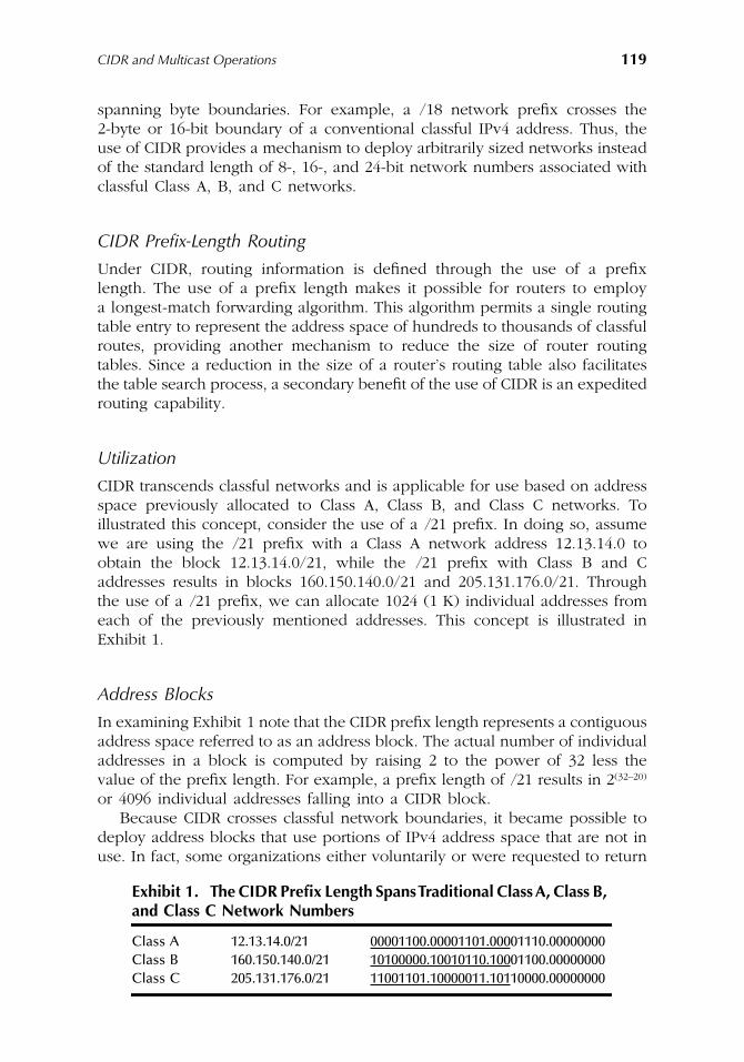
CIDR and Multicast Operations
119
spanning byte boundaries. For example, a /18 network prefix crosses the2-byte or 16-bit boundary of a conventional classful IPv4 address. Thus, theuse of CIDR provides a mechanism to deploy arbitrarily sized networks insteadof the standard length of 8-, 16-, and 24-bit network numbers associated withclassful Class A, B, and C networks.
CIDR Prefix-Length Routing
Under CIDR, routing information is defined through the use of a prefixlength. The use of a prefix length makes it possible for routers to employa longest-match forwarding algorithm. This algorithm permits a single routingtable entry to represent the address space of hundreds to thousands of classfulroutes, providing another mechanism to reduce the size of router routingtables. Since a reduction in the size of a router’s routing table also facilitatesthe table search process, a secondary benefit of the use of CIDR is an expeditedrouting capability.
Utilization
CIDR transcends classful networks and is applicable for use based on addressspace previously allocated to Class A, Class B, and Class C networks. Toillustrated this concept, consider the use of a /21 prefix. In doing so, assumewe are using the /21 prefix with a Class A network address 12.13.14.0 toobtain the block 12.13.14.0/21, while the /21 prefix with Class B and Caddresses results in blocks 160.150.140.0/21 and 205.131.176.0/21. Throughthe use of a /21 prefix, we can allocate 1024 (1 K) individual addresses fromeach of the previously mentioned addresses. This concept is illustrated inExhibit 1.
Address Blocks
In examining Exhibit 1 note that the CIDR prefix length represents a contiguousaddress space referred to as an address block. The actual number of individualaddresses in a block is computed by raising 2 to the power of 32 less thevalue of the prefix length. For example, a prefix length of /21 results in 2
(32–20)
or 4096 individual addresses falling into a CIDR block.Because CIDR crosses classful network boundaries, it became possible to
deploy address blocks that use portions of IPv4 address space that are not inuse. In fact, some organizations either voluntarily or were requested to return
Exhibit 1. The CIDR Prefix Length Spans Traditional Class A, Class B,
and Class C Network Numbers
Class A 12.13.14.0/21 00001100.00001101.00001110.00000000Class B 160.150.140.0/21 10100000.10010110.10001100.00000000Class C 205.131.176.0/21 11001101.10000011.10110000.00000000
AU1144_ch06_fm Page 119 Thursday, October 11, 2001 1:29 PM
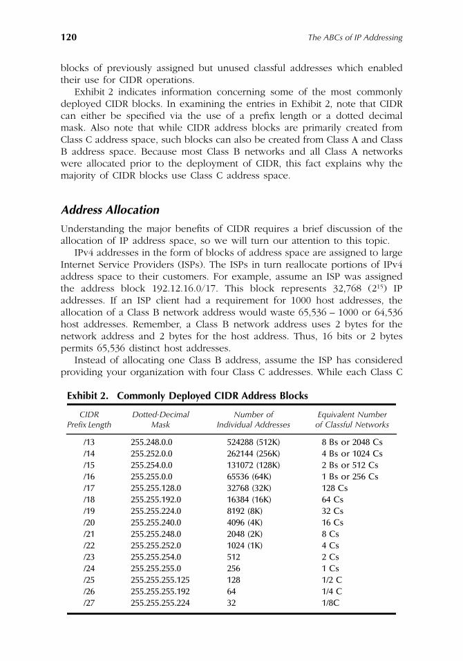
120
The ABCs of IP Addressing
blocks of previously assigned but unused classful addresses which enabledtheir use for CIDR operations.
Exhibit 2 indicates information concerning some of the most commonlydeployed CIDR blocks. In examining the entries in Exhibit 2, note that CIDRcan either be specified via the use of a prefix length or a dotted decimalmask. Also note that while CIDR address blocks are primarily created fromClass C address space, such blocks can also be created from Class A and ClassB address space. Because most Class B networks and all Class A networkswere allocated prior to the deployment of CIDR, this fact explains why themajority of CIDR blocks use Class C address space.
Address Allocation
Understanding the major benefits of CIDR requires a brief discussion of theallocation of IP address space, so we will turn our attention to this topic.
IPv4 addresses in the form of blocks of address space are assigned to largeInternet Service Providers (ISPs). The ISPs in turn reallocate portions of IPv4address space to their customers. For example, assume an ISP was assignedthe address block 192.12.16.0/17. This block represents 32,768 (2
15
) IPaddresses. If an ISP client had a requirement for 1000 host addresses, theallocation of a Class B network address would waste 65,536 – 1000 or 64,536host addresses. Remember, a Class B network address uses 2 bytes for thenetwork address and 2 bytes for the host address. Thus, 16 bits or 2 bytespermits 65,536 distinct host addresses.
Instead of allocating one Class B address, assume the ISP has consideredproviding your organization with four Class C addresses. While each Class C
Exhibit 2. Commonly Deployed CIDR Address Blocks
CIDR Prefix Length
Dotted-Decimal Mask
Number of Individual Addresses
Equivalent Number of Classful Networks
/13 255.248.0.0 524288 (512K) 8 Bs or 2048 Cs/14 255.252.0.0 262144 (256K) 4 Bs or 1024 Cs/15 255.254.0.0 131072 (128K) 2 Bs or 512 Cs/16 255.255.0.0 65536 (64K) 1 Bs or 256 Cs/17 255.255.128.0 32768 (32K) 128 Cs/18 255.255.192.0 16384 (16K) 64 Cs/19 255.255.224.0 8192 (8K) 32 Cs/20 255.255.240.0 4096 (4K) 16 Cs/21 255.255.248.0 2048 (2K) 8 Cs/22 255.255.252.0 1024 (1K) 4 Cs/23 255.255.254.0 512 2 Cs/24 255.255.255.0 256 1 Cs/25 255.255.255.125 128 1/2 C/26 255.255.255.192 64 1/4 C/27 255.255.255.224 32 1/8C
AU1144_ch06_fm Page 120 Thursday, October 11, 2001 1:29 PM
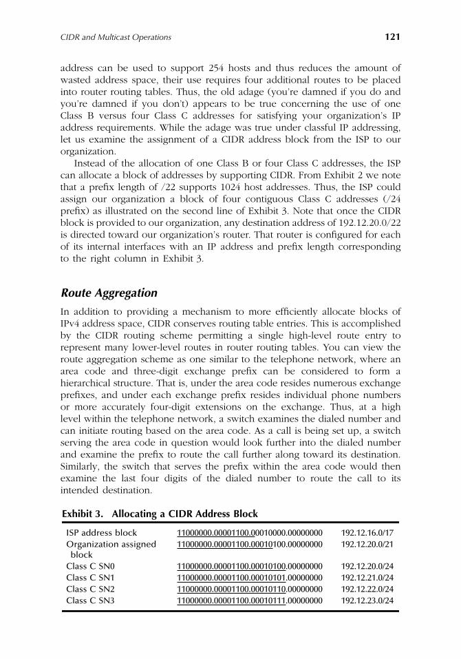
CIDR and Multicast Operations
121
address can be used to support 254 hosts and thus reduces the amount ofwasted address space, their use requires four additional routes to be placedinto router routing tables. Thus, the old adage (you’re damned if you do andyou’re damned if you don’t) appears to be true concerning the use of oneClass B versus four Class C addresses for satisfying your organization’s IPaddress requirements. While the adage was true under classful IP addressing,let us examine the assignment of a CIDR address block from the ISP to ourorganization.
Instead of the allocation of one Class B or four Class C addresses, the ISPcan allocate a block of addresses by supporting CIDR. From Exhibit 2 we notethat a prefix length of /22 supports 1024 host addresses. Thus, the ISP couldassign our organization a block of four contiguous Class C addresses (/24prefix) as illustrated on the second line of Exhibit 3. Note that once the CIDRblock is provided to our organization, any destination address of 192.12.20.0/22is directed toward our organization’s router. That router is configured for eachof its internal interfaces with an IP address and prefix length correspondingto the right column in Exhibit 3.
Route Aggregation
In addition to providing a mechanism to more efficiently allocate blocks ofIPv4 address space, CIDR conserves routing table entries. This is accomplishedby the CIDR routing scheme permitting a single high-level route entry torepresent many lower-level routes in router routing tables. You can view theroute aggregation scheme as one similar to the telephone network, where anarea code and three-digit exchange prefix can be considered to form ahierarchical structure. That is, under the area code resides numerous exchangeprefixes, and under each exchange prefix resides individual phone numbersor more accurately four-digit extensions on the exchange. Thus, at a highlevel within the telephone network, a switch examines the dialed number andcan initiate routing based on the area code. As a call is being set up, a switchserving the area code in question would look further into the dialed numberand examine the prefix to route the call further along toward its destination.Similarly, the switch that serves the prefix within the area code would thenexamine the last four digits of the dialed number to route the call to itsintended destination.
Exhibit 3. Allocating a CIDR Address Block
ISP address block 11000000.00001100.00010000.00000000 192.12.16.0/17Organization assigned
block11000000.00001100.00010100.00000000 192.12.20.0/21
Class C SN0 11000000.00001100.00010100.00000000 192.12.20.0/24Class C SN1 11000000.00001100.00010101.00000000 192.12.21.0/24Class C SN2 11000000.00001100.00010110.00000000 192.12.22.0/24Class C SN3 11000000.00001100.00010111.00000000 192.12.23.0/24
AU1144_ch06_fm Page 121 Thursday, October 11, 2001 1:29 PM
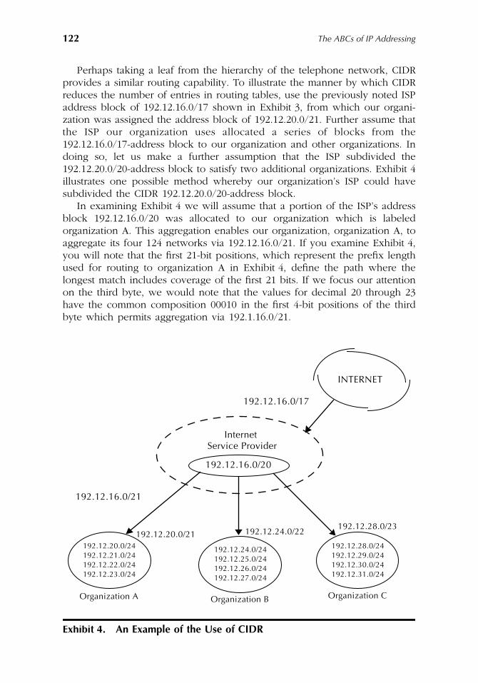
122
The ABCs of IP Addressing
Perhaps taking a leaf from the hierarchy of the telephone network, CIDRprovides a similar routing capability. To illustrate the manner by which CIDRreduces the number of entries in routing tables, use the previously noted ISPaddress block of 192.12.16.0/17 shown in Exhibit 3, from which our organi-zation was assigned the address block of 192.12.20.0/21. Further assume thatthe ISP our organization uses allocated a series of blocks from the192.12.16.0/17-address block to our organization and other organizations. Indoing so, let us make a further assumption that the ISP subdivided the192.12.20.0/20-address block to satisfy two additional organizations. Exhibit 4illustrates one possible method whereby our organization’s ISP could havesubdivided the CIDR 192.12.20.0/20-address block.
In examining Exhibit 4 we will assume that a portion of the ISP’s addressblock 192.12.16.0/20 was allocated to our organization which is labeledorganization A. This aggregation enables our organization, organization A, toaggregate its four 124 networks via 192.12.16.0/21. If you examine Exhibit 4,you will note that the first 21-bit positions, which represent the prefix lengthused for routing to organization A in Exhibit 4, define the path where thelongest match includes coverage of the first 21 bits. If we focus our attentionon the third byte, we would note that the values for decimal 20 through 23have the common composition 00010 in the first 4-bit positions of the thirdbyte which permits aggregation via 192.1.16.0/21.
Exhibit 4.
An Example of the Use of CIDR
INTERNET
Internet Service Provider
192.12.16.0/17
192.12.16.0/20
192.12.16.0/21
192.12.20.0/21 192.12.24.0/22192.12.28.0/23
192.12.20.0/24192.12.21.0/24192.12.22.0/24192.12.23.0/24
192.12.24.0/24192.12.25.0/24192.12.26.0/24192.12.27.0/24
192.12.28.0/24192.12.29.0/24192.12.30.0/24192.12.31.0/24
Organization A Organization B Organization C
AU1144_ch06_fm Page 122 Thursday, October 11, 2001 1:29 PM
CIDR and Multicast Operations
123
Similarly, for organization B, whose network values range from192.12.24.0/24 through 192.12.27.0/24, the common bit composition of thefirst five positions in the third byte becomes 00011, resulting in the need tomatch 6 bits in the third byte to differentiate one network from another. Thus16 + 6 results in 192.12.24.0/22 becoming the common route advertisement.
Continuing our examination of Exhibit 4, note that organization C has fourseparate blocks of addresses that are aggregated into a single routing address.To provide a path to organization C requires matching through one additionalbit position. Thus, the prefix length becomes 123 for the aggregation whilethe network address prefix becomes 192.12.28/23.
Based on the preceding, the CIDR address 192.12.16.0/20 is the only addressthat needs to be advertised from the ISP to the Internet. Once a datagramwith a destination address within the 192.12.16.0/20 block arrives at the ISP,the ISP must determine where the datagram must be routed. To accomplishthis task, ISP routers compare the destination address by extending a bit-matching process until a longest prefix-length match occurs. Thus, if a matchoccurs using a prefix length of /21, the datagram is routed toward organization A.In comparison, if a match occurs using a prefix length of /22, the datagramis routed toward organization B, while a match occurring using a prefix lengthof /23 results in the datagram being routed toward organization C.
Multicasting
In Chapter 2 when we discussed IPv4 addressing, we noted that a Class Daddress was employed for a function referred to as multicasting. We also notedthat multicasting and the use of a multicast address provides a mechanism tolimit the number of transmissions flowing onto a network; however, until nowa detailed description of how multicasting occurs was deferred. We will nowturn attention to multicasting and the use of Class D addresses in this section.
Overview
To obtain an appreciation for the role of multicasting, we will review itsoperation in context with the other two types of addresses supported underIPv4 — unicast and broadcast.
Unicast Addressing
The most common form of IPv4 addressing is unicast addressing. Under unicastaddressing, a host communicates on an individual basis with other hosts. Thatis, a host requiring communications with another Class A, Class B, or ClassC address adds an IP header with the applicable destination address to a TCPsegment or UDP datagram to form an IP datagram. Then, the IP datagram isrouted to a single destination based on the value of the destination addressin the header. The top portion of Exhibit 5 illustrates unicast transmission.
AU1144_ch06_fm Page 123 Thursday, October 11, 2001 1:29 PM
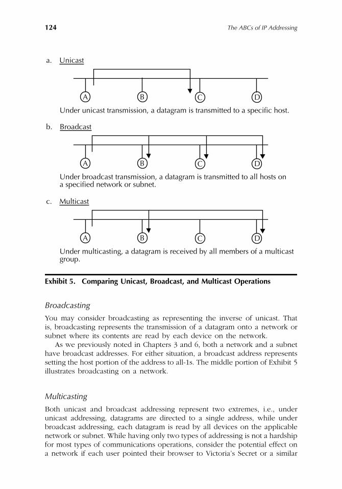
124
The ABCs of IP Addressing
Broadcasting
You may consider broadcasting as representing the inverse of unicast. Thatis, broadcasting represents the transmission of a datagram onto a network orsubnet where its contents are read by each device on the network.
As we previously noted in Chapters 3 and 6, both a network and a subnethave broadcast addresses. For either situation, a broadcast address representssetting the host portion of the address to all-1s. The middle portion of Exhibit 5illustrates broadcasting on a network.
Multicasting
Both unicast and broadcast addressing represent two extremes, i.e., underunicast addressing, datagrams are directed to a single address, while underbroadcast addressing, each datagram is read by all devices on the applicablenetwork or subnet. While having only two types of addressing is not a hardshipfor most types of communications operations, consider the potential effect ona network if each user pointed their browser to Victoria’s Secret or a similar
Exhibit 5. Comparing Unicast, Broadcast, and Multicast Operations
a. Unicast
Under unicast transmission, a datagram is transmitted to a specific host.
A B C D
b. Broadcast
Under broadcast transmission, a datagram is transmitted to all hosts on
A B C D
a specified network or subnet.
c. Multicast
Under multicasting, a datagram is received by all members of a multicast
A B C D
group.
AU1144_ch06_fm Page 124 Thursday, October 11, 2001 1:29 PM
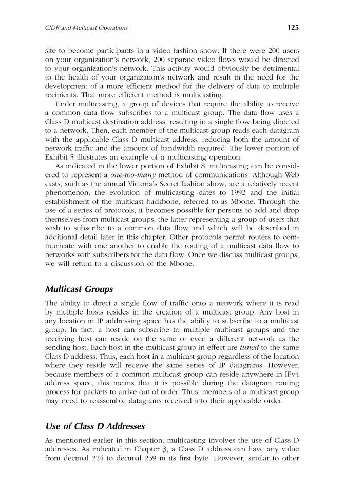
CIDR and Multicast Operations
125
site to become participants in a video fashion show. If there were 200 userson your organization’s network, 200 separate video flows would be directedto your organization’s network. This activity would obviously be detrimentalto the health of your organization’s network and result in the need for thedevelopment of a more efficient method for the delivery of data to multiplerecipients. That more efficient method is multicasting.
Under multicasting, a group of devices that require the ability to receivea common data flow subscribes to a multicast group. The data flow uses aClass D multicast destination address, resulting in a single flow being directedto a network. Then, each member of the multicast group reads each datagramwith the applicable Class D multicast address, reducing both the amount ofnetwork traffic and the amount of bandwidth required. The lower portion ofExhibit 5 illustrates an example of a multicasting operation.
As indicated in the lower portion of Exhibit 8, multicasting can be consid-ered to represent a
one-too-many
method of communications. Although Webcasts, such as the annual Victoria’s Secret fashion show, are a relatively recentphenomenon, the evolution of multicasting dates to 1992 and the initialestablishment of the multicast backbone, referred to as Mbone. Through theuse of a series of protocols, it becomes possible for persons to add and dropthemselves from multicast groups, the latter representing a group of users thatwish to subscribe to a common data flow and which will be described inadditional detail later in this chapter. Other protocols permit routers to com-municate with one another to enable the routing of a multicast data flow tonetworks with subscribers for the data flow. Once we discuss multicast groups,we will return to a discussion of the Mbone.
Multicast Groups
The ability to direct a single flow of traffic onto a network where it is readby multiple hosts resides in the creation of a multicast group. Any host inany location in IP addressing space has the ability to subscribe to a multicastgroup. In fact, a host can subscribe to multiple multicast groups and thereceiving host can reside on the same or even a different network as thesending host. Each host in the multicast group in effect are
tuned
to the sameClass D address. Thus, each host in a multicast group regardless of the locationwhere they reside will receive the same series of IP datagrams. However,because members of a common multicast group can reside anywhere in IPv4address space, this means that it is possible during the datagram routingprocess for packets to arrive out of order. Thus, members of a multicast groupmay need to reassemble datagrams received into their applicable order.
Use of Class D Addresses
As mentioned earlier in this section, multicasting involves the use of Class Daddresses. As indicated in Chapter 3, a Class D address can have any valuefrom decimal 224 to decimal 239 in its first byte. However, similar to other
AU1144_ch06_fm Page 125 Thursday, October 11, 2001 1:29 PM
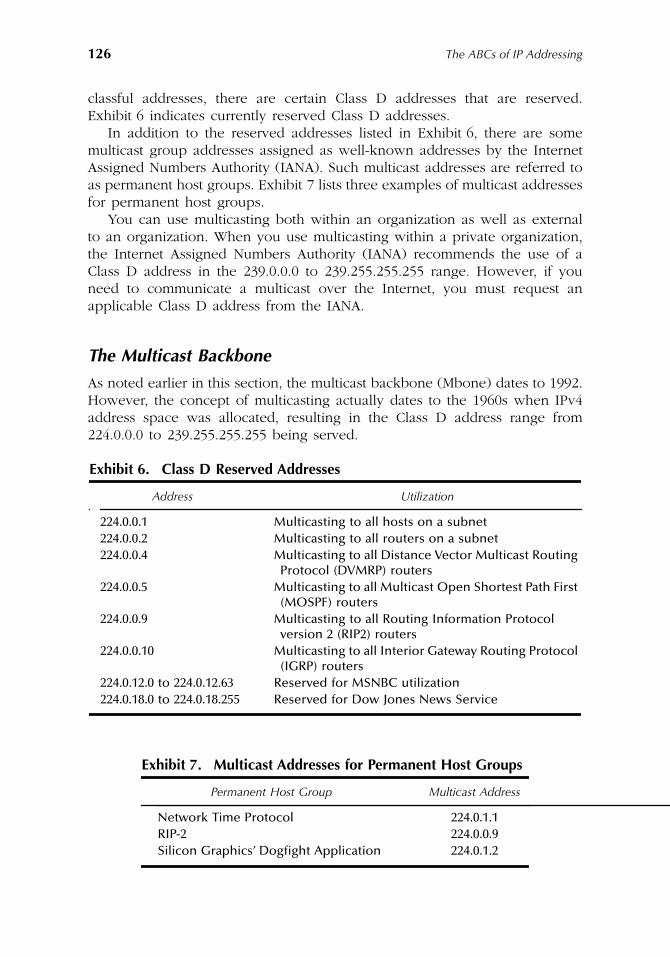
126
The ABCs of IP Addressing
classful addresses, there are certain Class D addresses that are reserved.Exhibit 6 indicates currently reserved Class D addresses.
In addition to the reserved addresses listed in Exhibit 6, there are somemulticast group addresses assigned as well-known addresses by the InternetAssigned Numbers Authority (IANA). Such multicast addresses are referred toas permanent host groups. Exhibit 7 lists three examples of multicast addressesfor permanent host groups.
You can use multicasting both within an organization as well as externalto an organization. When you use multicasting within a private organization,the Internet Assigned Numbers Authority (IANA) recommends the use of aClass D address in the 239.0.0.0 to 239.255.255.255 range. However, if youneed to communicate a multicast over the Internet, you must request anapplicable Class D address from the IANA.
The Multicast Backbone
As noted earlier in this section, the multicast backbone (Mbone) dates to 1992.However, the concept of multicasting actually dates to the 1960s when IPv4address space was allocated, resulting in the Class D address range from224.0.0.0 to 239.255.255.255 being served.
Exhibit 6. Class D Reserved Addresses
Address Utilization
224.0.0.1 Multicasting to all hosts on a subnet224.0.0.2 Multicasting to all routers on a subnet224.0.0.4 Multicasting to all Distance Vector Multicast Routing
Protocol (DVMRP) routers224.0.0.5 Multicasting to all Multicast Open Shortest Path First
(MOSPF) routers224.0.0.9 Multicasting to all Routing Information Protocol
version 2 (RIP2) routers224.0.0.10 Multicasting to all Interior Gateway Routing Protocol
(IGRP) routers224.0.12.0 to 224.0.12.63 Reserved for MSNBC utilization224.0.18.0 to 224.0.18.255 Reserved for Dow Jones News Service
Exhibit 7. Multicast Addresses for Permanent Host Groups
Permanent Host Group Multicast Address
Network Time Protocol 224.0.1.1RIP-2 224.0.0.9Silicon Graphics’ Dogfight Application 224.0.1.2
AU1144_ch06_fm Page 126 Thursday, October 11, 2001 1:29 PM
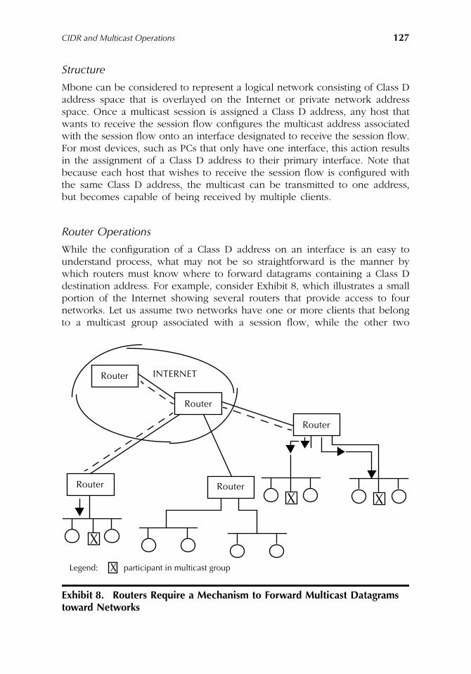
CIDR and Multicast Operations
127
Structure
Mbone can be considered to represent a logical network consisting of Class Daddress space that is overlayed on the Internet or private network addressspace. Once a multicast session is assigned a Class D address, any host thatwants to receive the session flow configures the multicast address associatedwith the session flow onto an interface designated to receive the session flow.For most devices, such as PCs that only have one interface, this action resultsin the assignment of a Class D address to their primary interface. Note thatbecause each host that wishes to receive the session flow is configured withthe same Class D address, the multicast can be transmitted to one address,but becomes capable of being received by multiple clients.
Router Operations
While the configuration of a Class D address on an interface is an easy tounderstand process, what may not be so straightforward is the manner bywhich routers must know where to forward datagrams containing a Class Ddestination address. For example, consider Exhibit 8, which illustrates a smallportion of the Internet showing several routers that provide access to fournetworks. Let us assume two networks have one or more clients that belongto a multicast group associated with a session flow, while the other two
Exhibit 8. Routers Require a Mechanism to Forward Multicast Datagrams toward Networks
INTERNETRouter
Router
Router
Router
X
RouterX X
Legend: participant in multicast groupX
AU1144_ch06_fm Page 127 Thursday, October 11, 2001 1:29 PM
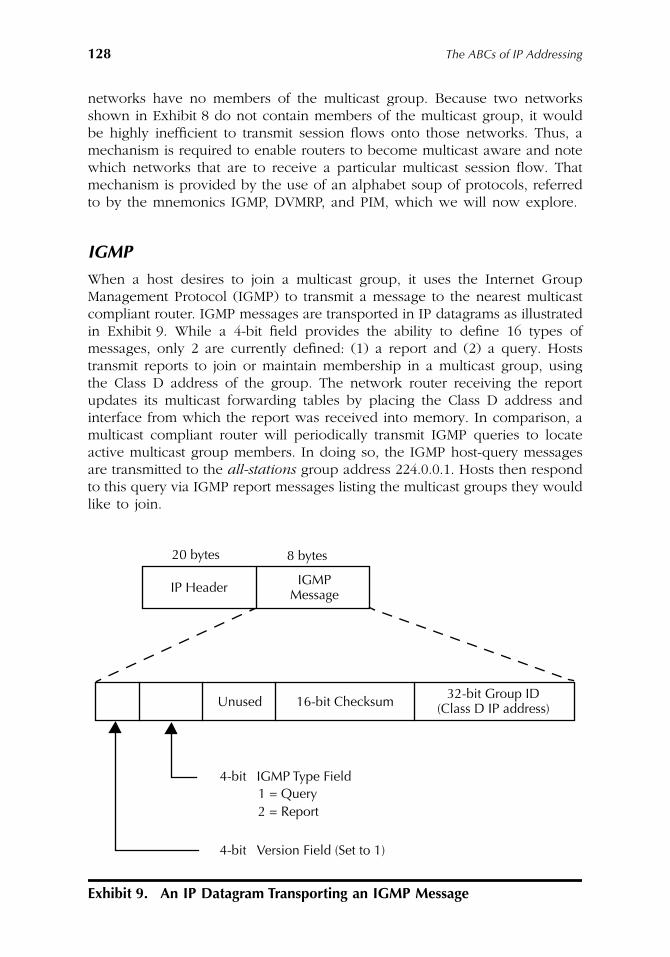
128
The ABCs of IP Addressing
networks have no members of the multicast group. Because two networksshown in Exhibit 8 do not contain members of the multicast group, it wouldbe highly inefficient to transmit session flows onto those networks. Thus, amechanism is required to enable routers to become multicast aware and notewhich networks that are to receive a particular multicast session flow. Thatmechanism is provided by the use of an alphabet soup of protocols, referredto by the mnemonics IGMP, DVMRP, and PIM, which we will now explore.
IGMP
When a host desires to join a multicast group, it uses the Internet GroupManagement Protocol (IGMP) to transmit a message to the nearest multicastcompliant router. IGMP messages are transported in IP datagrams as illustratedin Exhibit 9. While a 4-bit field provides the ability to define 16 types ofmessages, only 2 are currently defined: (1) a report and (2) a query. Hoststransmit reports to join or maintain membership in a multicast group, usingthe Class D address of the group. The network router receiving the reportupdates its multicast forwarding tables by placing the Class D address andinterface from which the report was received into memory. In comparison, amulticast compliant router will periodically transmit IGMP queries to locateactive multicast group members. In doing so, the IGMP host-query messagesare transmitted to the
all-stations
group address 224.0.0.1. Hosts then respondto this query via IGMP report messages listing the multicast groups they wouldlike to join.
Exhibit 9. An IP Datagram Transporting an IGMP Message
20 bytes 8 bytes
IP Header IGMPMessage
Unused 16-bit Checksum32-bit Group ID
(Class D IP address)
4-bit IGMP Type Field1 = Query2 = Report
4-bit Version Field (Set to 1)
AU1144_ch06_fm Page 128 Thursday, October 11, 2001 1:29 PM
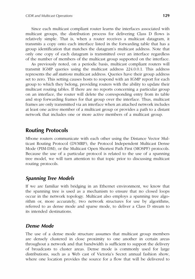
CIDR and Multicast Operations
129
Since each multicast compliant router learns the interfaces associated withmulticast groups, the distribution process for delivering Class D flows isrelatively simple. That is, when a router receives a multicast datagram, ittransmits a copy onto each interface listed in the forwarding table that has agroup identification that matches the datagram’s multicast address. Note thatonly one copy of each datagram is transmitted over an interface regardlessof the number of members of the multicast group supported on the interface.
As previously noted, on a periodic basis, multicast compliant routers willtransmit IGMP queries using the multicast address 224.0.0.1. This addressrepresents the
all stations
multicast address. Queries have their group addressset to zero. This setting causes hosts to respond with an IGMP report for eachgroup to which they belong, providing routers with the ability to update theirmulticast routing tables. If there are no reports concerning a particular groupon an interface, the router will delete the corresponding entry from its tableand stop forwarding frames for that group over the interface. Thus, multicastframes are only transmitted via an interface when an attached network includesat least one active member of a multicast group or provides a path to a distantnetwork that includes one or more active members of a multicast group.
Routing Protocols
Mbone routers communicate with each other using the Distance Vector Mul-ticast Routing Protocol (DVMRP), the Protocol Independent Multicast DenseMode (PIM-DM), or the Multicast Open Shortest Path First (MOSPF) protocols.Because the use of a particular protocol is related to the use of a spanningtree model, we will turn attention to that topic prior to discussing multicastrouting protocols.
Spanning Tree Models
If we are familiar with bridging in an Ethernet environment, we know thatthe spanning tree is used as a mechanism to ensure that no closed loopsoccur in the network topology. Multicast also employs a spanning tree algo-rithm or, more accurately, two network structures for use by algorithms,referred to as dense mode and sparse mode, to deliver a Class D stream toits intended destinations.
Dense Mode
The use of a dense mode structure assumes that multicast group membersare densely clustered in close proximity to one another in certain areasthroughout a network and that bandwidth is sufficient to support the deliveryof broadcasts to cluster areas. Dense mode is commonly used for largedistributions, such as a Web cast of Victoria’s Secret annual fashion show,where one location provides the source for a flow that will be delivered to
AU1144_ch06_fm Page 129 Thursday, October 11, 2001 1:29 PM
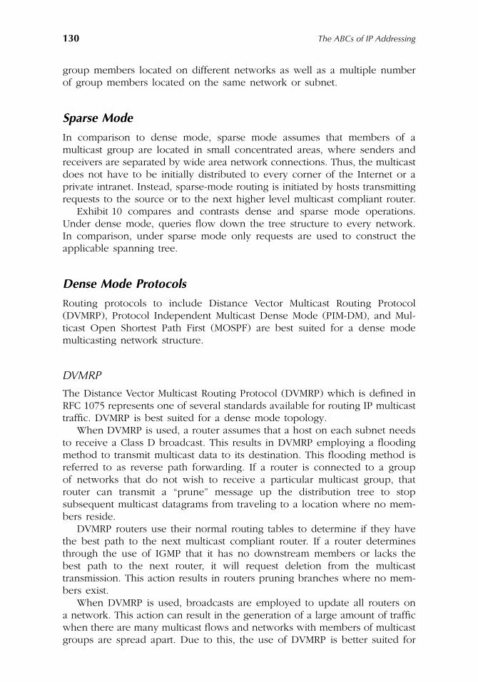
130
The ABCs of IP Addressing
group members located on different networks as well as a multiple numberof group members located on the same network or subnet.
Sparse Mode
In comparison to dense mode, sparse mode assumes that members of amulticast group are located in small concentrated areas, where senders andreceivers are separated by wide area network connections. Thus, the multicastdoes not have to be initially distributed to every corner of the Internet or aprivate intranet. Instead, sparse-mode routing is initiated by hosts transmittingrequests to the source or to the next higher level multicast compliant router.
Exhibit 10 compares and contrasts dense and sparse mode operations.Under dense mode, queries flow down the tree structure to every network.In comparison, under sparse mode only requests are used to construct theapplicable spanning tree.
Dense Mode Protocols
Routing protocols to include Distance Vector Multicast Routing Protocol(DVMRP), Protocol Independent Multicast Dense Mode (PIM-DM), and Mul-ticast Open Shortest Path First (MOSPF) are best suited for a dense modemulticasting network structure.
DVMRP
The Distance Vector Multicast Routing Protocol (DVMRP) which is defined inRFC 1075 represents one of several standards available for routing IP multicasttraffic. DVMRP is best suited for a dense mode topology.
When DVMRP is used, a router assumes that a host on each subnet needsto receive a Class D broadcast. This results in DVMRP employing a floodingmethod to transmit multicast data to its destination. This flooding method isreferred to as reverse path forwarding. If a router is connected to a groupof networks that do not wish to receive a particular multicast group, thatrouter can transmit a “prune” message up the distribution tree to stopsubsequent multicast datagrams from traveling to a location where no mem-bers reside.
DVMRP routers use their normal routing tables to determine if they havethe best path to the next multicast compliant router. If a router determinesthrough the use of IGMP that it has no downstream members or lacks thebest path to the next router, it will request deletion from the multicasttransmission. This action results in routers pruning branches where no mem-bers exist.
When DVMRP is used, broadcasts are employed to update all routers ona network. This action can result in the generation of a large amount of trafficwhen there are many multicast flows and networks with members of multicastgroups are spread apart. Due to this, the use of DVMRP is better suited for
AU1144_ch06_fm Page 130 Thursday, October 11, 2001 1:29 PM
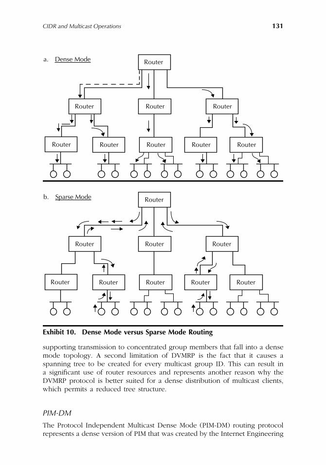
CIDR and Multicast Operations
131
supporting transmission to concentrated group members that fall into a densemode topology. A second limitation of DVMRP is the fact that it causes aspanning tree to be created for every multicast group ID. This can result ina significant use of router resources and represents another reason why theDVMRP protocol is better suited for a dense distribution of multicast clients,which permits a reduced tree structure.
PIM-DM
The Protocol Independent Multicast Dense Mode (PIM-DM) routing protocolrepresents a dense version of PIM that was created by the Internet Engineering
Exhibit 10. Dense Mode versus Sparse Mode Routing
a. Dense Mode Router
Router
Router
RouterRouter Router Router
Router Router
b. Sparse Mode Router
Router
Router
RouterRouter Router Router
Router Router
AU1144_ch06_fm Page 131 Thursday, October 11, 2001 1:29 PM
132
The ABCs of IP Addressing
Task Force (IETF). The goal of the development of PIM-DM was to obtain ascaleable multicast routing protocol that could operate efficiently across themultiple backbones of the public Internet as well as private networks. Inaddition, the PIM-DM protocol was also developed to provide independencefrom a particular unicast routing algorithm because it works with all existingunicast routing protocols.
Dense Mode PIM is similar to DVMRP in that it also uses a reverse pathforwarding method. When a router receives a multicast datagram, it transmitsthe datagram onto all interfaces other than the one on which it was received.
Although PIM-DM was designed as a relatively simple protocol, its simplicityalso represents a disadvantage with respect to its operation. For example,consider the manner by which this protocol operates when a datagram arrivesat a multicast compliant router supporting PIM-DM. PIM-DM determines if itis using the shortest path back to the source. If it is, the router forwardspackets onto all downstream interfaces until they reach networks with mem-bers of the applicable multicast group. This means it becomes possible formultiple copies of a multicast datagram to flow onto downstream networks.An example of this datagram duplication is shown in Exhibit 11. In thisexample, a host on the network at the top of the tree transmits a multicastdatagram to Group 1 that flows to router A. Router A duplicates each datagram,transmitting packets out on interface 1 and 2 to routers B and C. Those routersduplicate the datagrams, transmitting them to routers D, E, and F.
To prevent flooding or saturating a network, PIM-DM routers need to keeptrack of multicast traffic and the interface on which such traffic arrives. Becauserouter E has a host that is a member of Group 1 and received datagrams ontwo interfaces, it would send a prune message to either router B or C. Theactual decision concerning which router should be pruned is reached througha negotiation process between routers B and C, adding additional traffic tothe network. Because router F does not have any hosts that are members ofGroup 1, that router would send a prune message to router C.
MOSPF
A third routing protocol employed in dense-mode networks is the MulticastOpen Shortest Path First (MOSPF). You can view MOSPF as an extension tothe OSPF protocol that was developed to support multicast transmission. UnderMOSPF, datagrams are routed over the least cost connection that has availablebandwidth, with the shortest hop count to the destination used as a metricto determine the most appropriate path. This routing method permits heavilycongested connections to be avoided since a highest cost in the form of hopcounts can be assigned to such routes.
A router supporting MOSPF uses link-state information flooded betweenrouters to develop a view of the entire network. Because IGMP data concerningrequests and reports as well as link state information is passed between routers,the use of MOSPF will reduce available bandwidth as the number of membersin a group located in a network increases. Another limitation of MOSPFconcerns its reliance on OSPF domains for the routing of traffic. Because OSPF
AU1144_ch06_fm Page 132 Thursday, October 11, 2001 1:29 PM
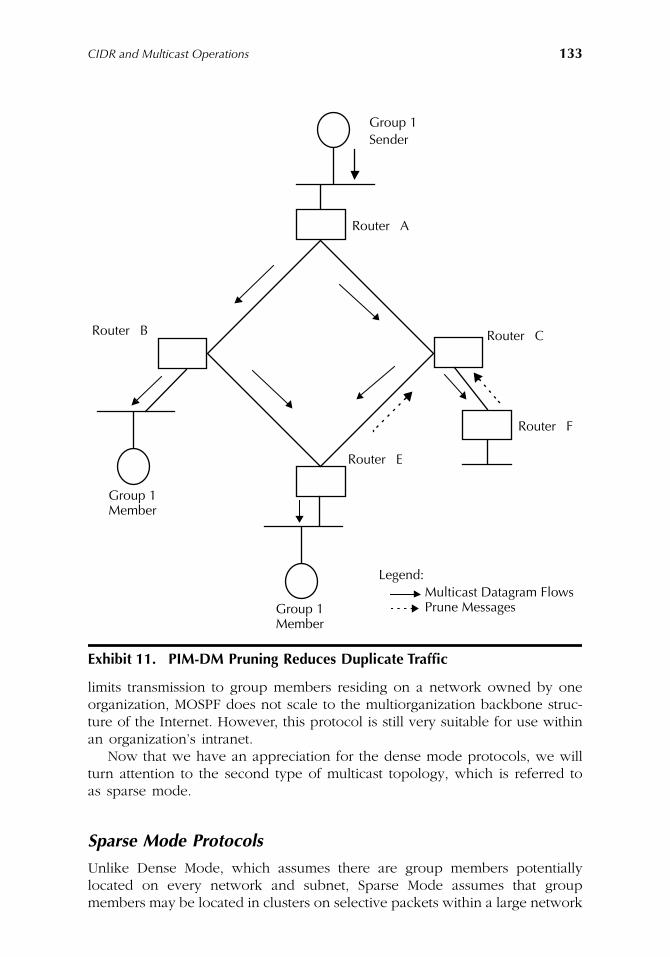
CIDR and Multicast Operations
133
limits transmission to group members residing on a network owned by oneorganization, MOSPF does not scale to the multiorganization backbone struc-ture of the Internet. However, this protocol is still very suitable for use withinan organization’s intranet.
Now that we have an appreciation for the dense mode protocols, we willturn attention to the second type of multicast topology, which is referred toas sparse mode.
Sparse Mode Protocols
Unlike Dense Mode, which assumes there are group members potentiallylocated on every network and subnet, Sparse Mode assumes that groupmembers may be located in clusters on selective packets within a large network
Exhibit 11. PIM-DM Pruning Reduces Duplicate Traffic
Group 1Sender
Router A
Router C
Router F
Router E
Router B
Group 1Member
Group 1Member
Legend:Multicast Datagram FlowsPrune Messages
AU1144_ch06_fm Page 133 Thursday, October 11, 2001 1:29 PM
134
The ABCs of IP Addressing
structure. This means it may not be necessary to transmit a multicast flowonto every network branch. Instead, Sparse Mode protocols construct routingtrees by requiring other routers to participate in creating the tree. In doingso, routers operating a Sparse Mode protocol only ask to join the tree whena client in the downstream direction requests admission to a multicast group.
There are two routing protocols that support the creation of a sparse modespanning tree topology. Those protocols are Core-Based Tree (CBT) andProtocol Independent Multicast Sparse Mode (PIM-SM). Each of these protocolsconstructs routing tables by requiring routers to participate in the creation ofa Sparse Mode tree. That tree is created based on Sparse Mode routers receivingan admission request from a downstream host. When this action occurs, therouter then informs its upstream neighbor that it wants to join a particularmulticast session.
Now that we have a general appreciation for the manner by which a sparsemode topology is created, we will turn attention to the two Sparse Moderouting protocols.
CBT
Under the Core-Based Tree (CBT) routing protocol, a common tree is createdthat is used by each multicast group. Under CBT, a core router is used tocontrol all data flows regardless of the source of the multicast session. Thus,the core router becomes the head of a tree structure used by all multicastgroups. While the use of a common tree reduces link-state information thatmust be transmitted between routers, the core router can become overloadedas additional hosts on different networks join one or more multicast groups.
When CBT is used, a group member will transmit an IGMP datagramupstream to the first multicast compliant router. If that router is alreadyreceiving the multicast session, it will now transmit the flow out of the interfacetoward the group member. Otherwise, the router will send a request upstreamtoward the core router. If this upstream request reaches a router that isreceiving the session, that router will add the member’s router to the distri-bution and direct the session in the downstream direction toward the member’sroute. If no upstream router is currently receiving the session, the request willeventually reach the core router that will enable the session to flow in theapplicable downstream direction.
Now that we have an appreciation for the manner by which CBT operates,our attention will turn to the second Sparse Mode routing protocol.
PIM-SM
The Protocol Independent Multicast Sparse Mode (PIM-SM) routing protocolreplaces the core router used by the CBT protocol with rendezvous point (RP)routers. The latter represents locations where downstream routers are clusteredand enables PIM-SM to create a shared tree based on the shortest path betweenrouters. While this results in a topology similar to CBT, it provides moreflexibility because each multicast group can have a different tree structure.
AU1144_ch06_fm Page 134 Thursday, October 11, 2001 1:29 PM
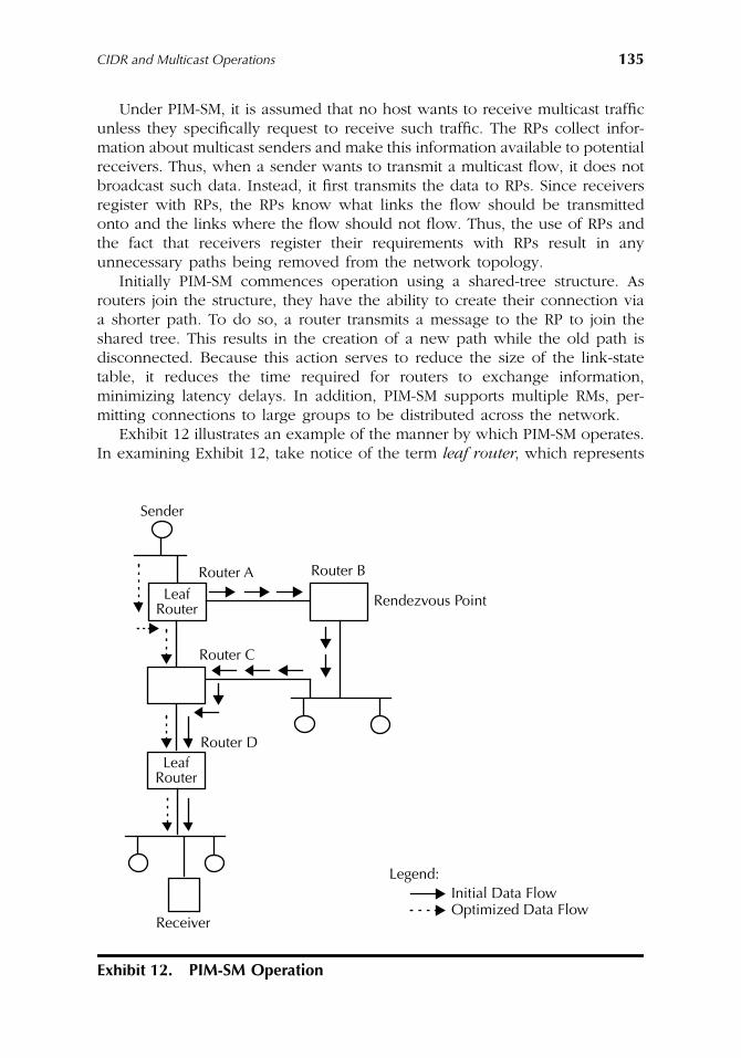
CIDR and Multicast Operations
135
Under PIM-SM, it is assumed that no host wants to receive multicast trafficunless they specifically request to receive such traffic. The RPs collect infor-mation about multicast senders and make this information available to potentialreceivers. Thus, when a sender wants to transmit a multicast flow, it does notbroadcast such data. Instead, it first transmits the data to RPs. Since receiversregister with RPs, the RPs know what links the flow should be transmittedonto and the links where the flow should not flow. Thus, the use of RPs andthe fact that receivers register their requirements with RPs result in anyunnecessary paths being removed from the network topology.
Initially PIM-SM commences operation using a shared-tree structure. Asrouters join the structure, they have the ability to create their connection viaa shorter path. To do so, a router transmits a message to the RP to join theshared tree. This results in the creation of a new path while the old path isdisconnected. Because this action serves to reduce the size of the link-statetable, it reduces the time required for routers to exchange information,minimizing latency delays. In addition, PIM-SM supports multiple RMs, per-mitting connections to large groups to be distributed across the network.
Exhibit 12 illustrates an example of the manner by which PIM-SM operates.In examining Exhibit 12, take notice of the term
leaf router
, which represents
Exhibit 12.
PIM-SM Operation
Legend:Initial Data FlowOptimized Data Flow
LeafRouter
LeafRouter
Sender
Router A Router B
Rendezvous Point
Router C
Router D
Receiver
AU1144_ch06_fm Page 135 Thursday, October 11, 2001 1:29 PM
136
The ABCs of IP Addressing
routers that are directly connected either to a sender or receiver of multicasttraffic. A leaf router designates one or more routers as RPs. In Exhibit 12assume that router B was designated as a rendezvous point. Under PIM-SM,the leaf router that is directly connected to a multicast sender transmits PIMregister messages on behalf of the sender to the RP. Thus, router A in Exhibit 12transmits PIM register messages to router B. Similarly, leaf routers directlyconnected to receivers transmit PIM join prune messages to RPs to inform therendezvous point about group membership. Thus, returning to Exhibit 12,router D would note it has a receiver and transmits a PIM join message torouter B. As a result of this, the initial data flow in which multicast transmissionflows from router A to router B to C and D would be optimized to avoidflowing to B.
SummaryAlthough there are numerous details to note when preparing for multicastrouting, in actuality the configuration of a router in most cases is a relativelysimple process. Once you determine the applicable protocol to support, youwould enable the protocol for operation on an applicable interface. While theexact router command or series of commands will vary based on the routerused, they typically involve a core set of commands. For example, to enablemulticast routing, you would use the command ip multicast-routing. Then,you would add one or more router commands based on the protocol selectedto support multicast routing. Thus, while many router manuals may not providea detailed explanation of topology modes, they should provide guidanceconcerning the applicable commands to use to support a particular topology.
AU1144_ch06_fm Page 136 Thursday, October 11, 2001 1:29 PM
137
Chapter 7
Network Address Translation
and IP Naming Services
Chapter 7 will focus on two topics that extend the use of IPv4 addressspace — (1) Network Address Translation (NAT) and (2) IP naming services.In the first section, we will examine how NAT provides us with the ability touse the RFC 1918 addresses behind a translating device, such as a firewall orrouter. We can then translate addresses behind the firewall or router into validIPv4 addresses for use on the Internet. Because the translation process permitsa significant reduction in the use of IPv4 public address space, NAT conservesthe use of IPv4 addresses.
In the second section, we will examine the operation and utilization of IPnaming services. Similar to NAT, IP naming services provide a mechanism forconserving the use of IPv4 addresses. However, instead of translating a largenumber of non-Internet ready addresses into a lesser number of Internet readyaddresses, the use of a naming service distributes addresses on a dynamicand normally temporary basis.
Network Address Translation
During the first two decades of the existence of the Internet, its use as amechanism to interconnect research laboratories and universities did notseverely tax the use of available IPv4 address space. However, commercial-ization of the Internet and the growth in the World Wide Web, the literalexplosion in the use of e-mail, and other applications considerably increasedthe rate of depletion of IPv4 address space. Although the Internet EngineeringTask Force (IETF) recognized the pending demise of available IPv4 addressspace and implemented work on IPv6, its availability was viewed as being inthe distant future. Thus, a short-term solution for extending IPv4 address space
AU1144_ch07_fm Page 137 Thursday, October 11, 2001 1:31 PM
138
The ABCs of IP Addressing
was required to enable growth of the Internet to continue. One of severalshort-term solutions occurred in 1994, with the publication of RFC 1631, “TheIP Network Address Translator.” When employed in conjunction with RFC1918, “Address Allocation for Private Internets,” it becomes possible for orga-nizations to use the same IP addresses behind their router or firewall and mapthose addresses into one or more valid IPv4 addresses based on one of severalmethods. For example, as noted earlier in this book, RFC 1918 defines threeblocks of private Internet addresses. As a review, those address blocks are:
10.0.0.0 to 10.255.255.255
172.16.0.0 to 172.31.255.255
192.168.0.0 to 192.168.255.255
Overview
Suppose our organization has several thousand workstations and servers. Ifour organization’s network is not connected to the Internet, we could theo-retically assign any IP addresses to our workstations and servers. However, ifwe intend to connect our organization’s network to the Internet, we need toacquire a recognized IPv4 address as well as have that address registered sorouters on the Internet know where to forward datagrams destined to thenetwork used by our organization. Due to the shortage of IPv4 addresses, wecould assign RFC 1918 addresses to our organization’s workstations and serversand map or translate those addresses into a lessor number of valid IPv4addresses. For example, we might use the 10.0.0.0 to 10.225.255.255 privateIP address block to assign private Class A addresses to 2000 network devices.We might then use NAT in conjunction with a single Class C public addressto map private Class A addresses to public Class C addresses on a dynamicbasis. Doing so would enable one Class C network address to be used insteadof eight. However, if more than 254 users simultaneously required Internetaccess, some user requests would either be denied or queued until a previouslyused Class C address becomes available for reuse.
Advantages of Use
As previously noted in this section, the use of NAT conserves scarce IPv4address space. However, that is not the only reason to use network addresstranslation. Two additional reasons for its use involve security and flexibility.
Concerning security, the address translation process hides hosts from directaccess from the public network. Therefore, NAT makes it more difficult foroutside users to determine the true structure of an organization’s network inan attempt to attack the network. Another reason to consider the use of NATconcerns network flexibility. If your organization changes the service provider,you may not be able to take your network address to a new Internet ServiceProvider. NAT mitigates the effect of having to obtain a new network addressbecause it allows readdressing to occur at the address translation device. This
AU1144_ch07_fm Page 138 Thursday, October 11, 2001 1:31 PM
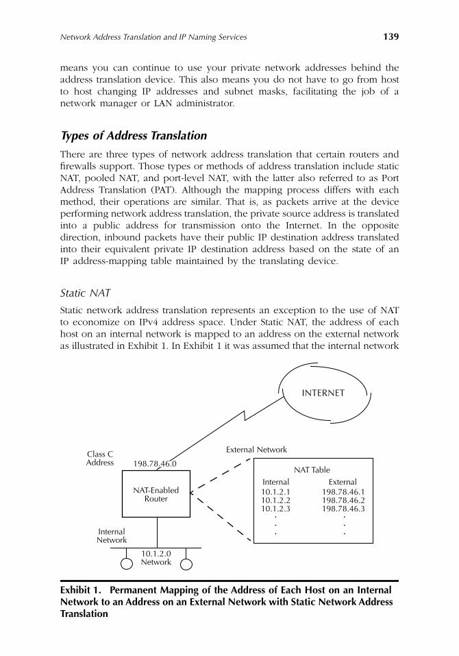
Network Address Translation and IP Naming Services
139
means you can continue to use your private network addresses behind theaddress translation device. This also means you do not have to go from hostto host changing IP addresses and subnet masks, facilitating the job of anetwork manager or LAN administrator.
Types of Address Translation
There are three types of network address translation that certain routers andfirewalls support. Those types or methods of address translation include staticNAT, pooled NAT, and port-level NAT, with the latter also referred to as PortAddress Translation (PAT). Although the mapping process differs with eachmethod, their operations are similar. That is, as packets arrive at the deviceperforming network address translation, the private source address is translatedinto a public address for transmission onto the Internet. In the oppositedirection, inbound packets have their public IP destination address translatedinto their equivalent private IP destination address based on the state of anIP address-mapping table maintained by the translating device.
Static NAT
Static network address translation represents an exception to the use of NATto economize on IPv4 address space. Under Static NAT, the address of eachhost on an internal network is mapped to an address on the external networkas illustrated in Exhibit 1. In Exhibit 1 it was assumed that the internal network
Exhibit 1. Permanent Mapping of the Address of Each Host on an Internal Network to an Address on an External Network with Static Network Address Translation
INTERNET
Class CAddress
NAT-EnabledRouter
InternalNetwork
10.1.2.0Network
External Network
NAT TableInternal10.1.2.110.1.2.210.1.2.3
External198.78.46.1198.78.46.2198.78.46.3
198.78.46.0
···
···
AU1144_ch07_fm Page 139 Thursday, October 11, 2001 1:31 PM
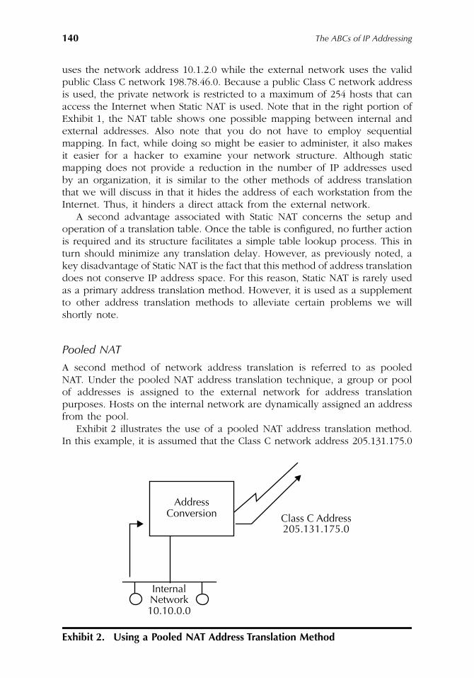
140
The ABCs of IP Addressing
uses the network address 10.1.2.0 while the external network uses the validpublic Class C network 198.78.46.0. Because a public Class C network addressis used, the private network is restricted to a maximum of 254 hosts that canaccess the Internet when Static NAT is used. Note that in the right portion ofExhibit 1, the NAT table shows one possible mapping between internal andexternal addresses. Also note that you do not have to employ sequentialmapping. In fact, while doing so might be easier to administer, it also makesit easier for a hacker to examine your network structure. Although staticmapping does not provide a reduction in the number of IP addresses usedby an organization, it is similar to the other methods of address translationthat we will discuss in that it hides the address of each workstation from theInternet. Thus, it hinders a direct attack from the external network.
A second advantage associated with Static NAT concerns the setup andoperation of a translation table. Once the table is configured, no further actionis required and its structure facilitates a simple table lookup process. This inturn should minimize any translation delay. However, as previously noted, akey disadvantage of Static NAT is the fact that this method of address translationdoes not conserve IP address space. For this reason, Static NAT is rarely usedas a primary address translation method. However, it is used as a supplementto other address translation methods to alleviate certain problems we willshortly note.
Pooled NAT
A second method of network address translation is referred to as pooledNAT. Under the pooled NAT address translation technique, a group or poolof addresses is assigned to the external network for address translationpurposes. Hosts on the internal network are dynamically assigned an addressfrom the pool.
Exhibit 2 illustrates the use of a pooled NAT address translation method.In this example, it is assumed that the Class C network address 205.131.175.0
Exhibit 2. Using a Pooled NAT Address Translation Method
10.10.0.0
InternalNetwork
AddressConversion Class C Address
205.131.175.0
AU1144_ch07_fm Page 140 Thursday, October 11, 2001 1:31 PM
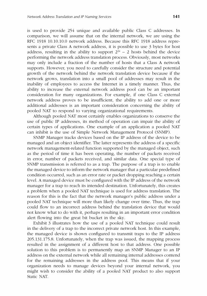
Network Address Translation and IP Naming Services
141
is used to provide 254 unique and available public Class C addresses. Incomparison, we will assume that on the internal network, we are using theRFC 1918 10.10.10.0 network address. Because this RFC 1918 address repre-sents a private Class A network address, it is possible to use 3 bytes for hostaddress, resulting in the ability to support 2
24
– 2 hosts behind the deviceperforming the network address translation process. Obviously, most networksmay only include a fraction of the number of hosts that a Class A networksupports. However, you need to carefully consider the structure and potentialgrowth of the network behind the network translation device because if thenetwork grows, translation into a small pool of addresses may result in theinability of employees to access the Internet in a timely manner. Thus, theability to increase the external network address pool can be an importantconsideration for many organizations. For example, if one Class C externalnetwork address proves to be insufficient, the ability to add one or moreadditional addresses is an important consideration concerning the ability ofpooled NAT to respond to varying organizational requirements.
Although pooled NAT most certainly enables organizations to conserve theuse of public IP addresses, its method of operation can impair the ability ofcertain types of applications. One example of an application a pooled NATcan inhibit is the use of Simple Network Management Protocol (SNMP).
SNMP Manager tracks devices based on the IP address of the device to bemanaged and an object identifier. The latter represents the address of a specificnetwork management-related function supported by the managed object, suchas the period of time it has been operating, the number of packets receivedin error, number of packets received, and similar data. One special type ofSNMP transmission is referred to as a trap. The purpose of a trap is to enablethe managed device to inform the network manager that a particular predefinedcondition occurred, such as an error rate or packet dropping reaching a certainlevel. A managed device must be configured with the IP address of the networkmanager for a trap to reach its intended destination. Unfortunately, this createsa problem when a pooled NAT technique is used for address translation. Thereason for this is the fact that the network manager’s public address under apooled NAT technique will more than likely change over time. Thus, the trapcould flow to an incorrect address behind the translation device that wouldnot know what to do with it, perhaps resulting in an important error conditionalert flowing into the great bit bucket in the sky.
Exhibit 3 illustrates how the use of a pooled NAT technique could resultin the delivery of a trap to the incorrect private network host. In this example,the managed device is shown configured to transmit traps to the IP address205.131.175.8. Unfortunately, when the trap was issued, the mapping processresulted in the assignment of a different host to that address. One possiblesolution to this problem is to permanently map an SNMP Manager to an IPaddress on the external network while all remaining internal addresses contendfor the remaining addresses in the address pool. This means that if yourorganization needs to manage devices beyond your internal network, youmight wish to consider the ability of a pooled NAT product to also supportStatic NAT.
AU1144_ch07_fm Page 141 Thursday, October 11, 2001 1:31 PM
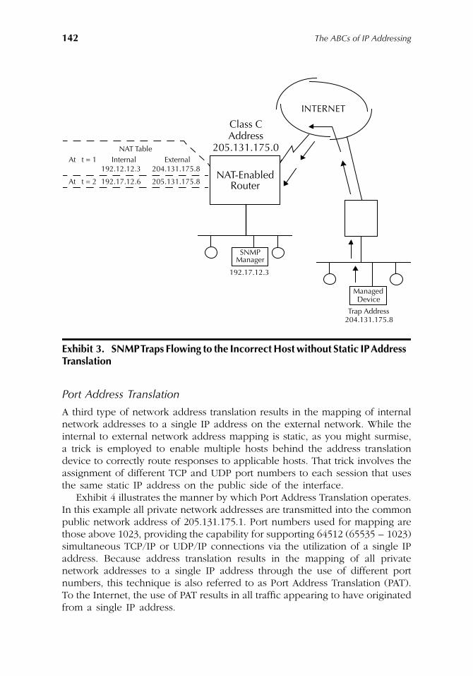
142
The ABCs of IP Addressing
Port Address Translation
A third type of network address translation results in the mapping of internalnetwork addresses to a single IP address on the external network. While theinternal to external network address mapping is static, as you might surmise,a trick is employed to enable multiple hosts behind the address translationdevice to correctly route responses to applicable hosts. That trick involves theassignment of different TCP and UDP port numbers to each session that usesthe same static IP address on the public side of the interface.
Exhibit 4 illustrates the manner by which Port Address Translation operates.In this example all private network addresses are transmitted into the commonpublic network address of 205.131.175.1. Port numbers used for mapping arethose above 1023, providing the capability for supporting 64512 (65535 – 1023)simultaneous TCP/IP or UDP/IP connections via the utilization of a single IPaddress. Because address translation results in the mapping of all privatenetwork addresses to a single IP address through the use of different portnumbers, this technique is also referred to as Port Address Translation (PAT).To the Internet, the use of PAT results in all traffic appearing to have originatedfrom a single IP address.
Exhibit 3. SNMP Traps Flowing to the Incorrect Host without Static IP Address Translation
INTERNET
Class C
NAT-EnabledRouter
Address205.131.175.0NAT Table
At t = 1 Internal External192.12.12.3 204.131.175.8
192.17.12.6 205.131.175.8At t = 2
SNMPManager
192.17.12.3
ManagedDevice
Trap Address204.131.175.8
AU1144_ch07_fm Page 142 Thursday, October 11, 2001 1:31 PM
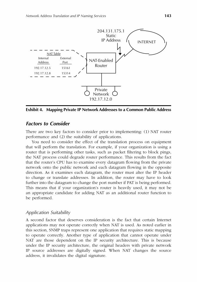
Network Address Translation and IP Naming Services
143
Factors to Consider
There are two key factors to consider prior to implementing: (1) NAT routerperformance and (2) the suitability of applications.
You need to consider the effect of the translation process on equipmentthat will perform the translation. For example, if your organization is using arouter that is performing other tasks, such as packet filtering to block pings,the NAT process could degrade router performance. This results from the factthat the router’s CPU has to examine every datagram flowing from the privatenetwork onto the public network and each datagram flowing in the oppositedirection. As it examines each datagram, the router must alter the IP headerto change or translate addresses. In addition, the router may have to lookfurther into the datagram to change the port number if PAT is being performed.This means that if your organization’s router is heavily used, it may not bean appropriate candidate for adding NAT as an additional router function tobe performed.
Application Suitability
A second factor that deserves consideration is the fact that certain Internetapplications may not operate correctly when NAT is used. As noted earlier inthis section, SNMP traps represent one application that requires static mappingto operate correctly. Another type of application that cannot operate underNAT are those dependent on the IP security architecture. This is becauseunder the IP security architecture, the original headers with private networkIP source addresses are digitally signed. When NAT changes the sourceaddress, it invalidates the digital signature.
Exhibit 4. Mapping Private IP Network Addresses to a Common Public Address
INTERNET
Private
192.17.12.0
NAT TableInternal External
192.17.12.5 15161
192.17.12.8 15314
Address Port
204.131.175.1
Network
StaticIP Address
NAT-EnabledRouter
AU1144_ch07_fm Page 143 Thursday, October 11, 2001 1:31 PM
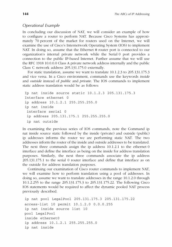
144
The ABCs of IP Addressing
Operational Example
In concluding our discussion of NAT, we will consider an example of howto configure a router to perform NAT. Because Cisco Systems has approxi-mately 70 percent of the market for routers used on the Internet, we willexamine the use of Cisco’s Internetwork Operating System (IOS) to implementNAT. In doing so, assume that the Ethernet 0 router port is connected to ourorganization’s internal private network while the Serial 0 port provides aconnection to the public IP-based Internet. Further assume that we will usethe RFC 1918 10.0.0.0 Class A private network address internally and the publicClass C network address 205.131.175.0 externally.
For static translation, assume we want to translate 10.1.2.3 to 205.131.175.3and vice versa. In a Cisco environment, commands use the keywords
inside
and
outside
instead of
public
and
private
. The IOS commands to implementstatic address translation would be as follows:
Ip nat inside source static 10.1.2.3 205.131.175.3Interface ethernet 0ip address 10.1.2.1 255.255.255.0ip nat insideinterface serial 0ip address 205.131.175.1 255.255.255.0
ip nat outside
In examining the previous series of IOS commands, note the Command ipnat inside source static followed by the inside (private) and outside (public)ip addresses informs the router we are performing static NAT. The twoaddresses inform the router of the inside and outside addresses to be translated.The next three commands assign the ip address 10.1.2.1 to the ethernet 0interface and define the interface as being on the inside for address translationpurposes. Similarly, the next three commands associate the ip address205.131.175.1 to the serial 0 router interface and define that interface as onthe outside for address translation purposes.
Continuing our examination of Cisco router commands to implement NAT,we will examine how to perform translation using a pool of addresses. Indoing so, assume we want to translate addresses in the range 10.1.2.0 through10.1.2.255 to the range 205.131.175.3 to 205.131.175.22. The following CiscoIOS statements would be required to affect the dynamic pooled NAT processpreviously described.
ip nat pool LegalPool 205.131.175.3 205.131.175.22
access-list 10 permit 10.1.2.0 0.0.0.255ip nat inside source list 10pool LegalPoolinside ethernet0ip address 10.1.2.1 255.255.255.0ip nat inside
AU1144_ch07_fm Page 144 Thursday, October 11, 2001 1:31 PM
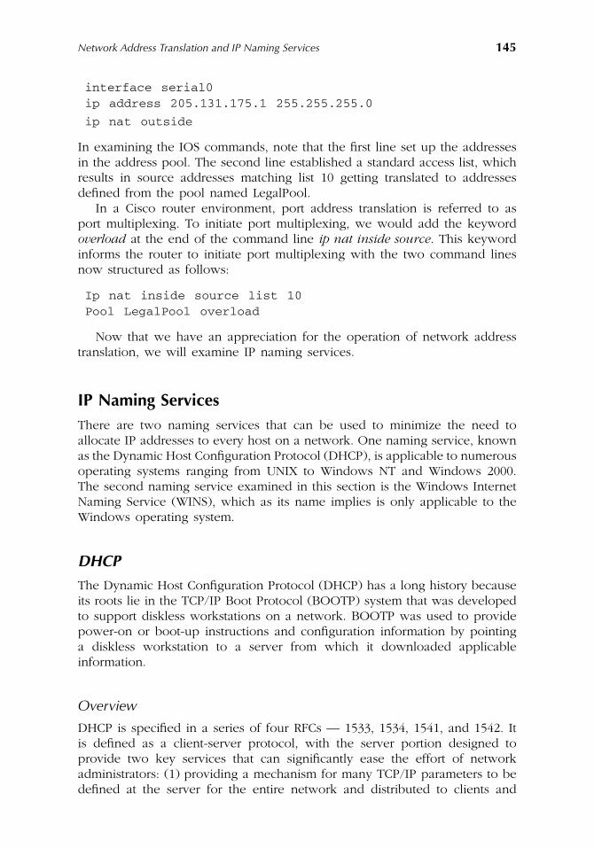
Network Address Translation and IP Naming Services
145
interface serial0ip address 205.131.175.1 255.255.255.0
ip nat outside
In examining the IOS commands, note that the first line set up the addressesin the address pool. The second line established a standard access list, whichresults in source addresses matching list 10 getting translated to addressesdefined from the pool named LegalPool.
In a Cisco router environment, port address translation is referred to asport multiplexing. To initiate port multiplexing, we would add the keyword
overload
at the end of the command line
ip nat inside source
. This keywordinforms the router to initiate port multiplexing with the two command linesnow structured as follows:
Ip nat inside source list 10Pool LegalPool overload
Now that we have an appreciation for the operation of network addresstranslation, we will examine IP naming services.
IP Naming Services
There are two naming services that can be used to minimize the need toallocate IP addresses to every host on a network. One naming service, knownas the Dynamic Host Configuration Protocol (DHCP), is applicable to numerousoperating systems ranging from UNIX to Windows NT and Windows 2000.The second naming service examined in this section is the Windows InternetNaming Service (WINS), which as its name implies is only applicable to theWindows operating system.
DHCP
The Dynamic Host Configuration Protocol (DHCP) has a long history becauseits roots lie in the TCP/IP Boot Protocol (BOOTP) system that was developedto support diskless workstations on a network. BOOTP was used to providepower-on or boot-up instructions and configuration information by pointinga diskless workstation to a server from which it downloaded applicableinformation.
Overview
DHCP is specified in a series of four RFCs — 1533, 1534, 1541, and 1542. Itis defined as a client-server protocol, with the server portion designed toprovide two key services that can significantly ease the effort of networkadministrators: (1) providing a mechanism for many TCP/IP parameters to bedefined at the server for the entire network and distributed to clients and
AU1144_ch07_fm Page 145 Thursday, October 11, 2001 1:31 PM
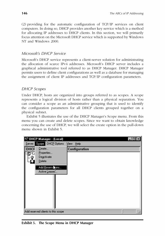
146
The ABCs of IP Addressing
(2) providing for the automatic configuration of TCP/IP services on clientcomputers. In doing so, DHCP provides another key service which is a methodfor allocating IP addresses to DHCP clients. In this section, we will primarilyfocus attention on the Microsoft DHCP service which is supported by WindowsNT and Windows 2000.
Microsoft’s DHCP Service
Microsoft’s DHCP service represents a client-server solution for administratingthe allocation of scarce IPv4 addresses. Microsoft’s DHCP server includes agraphical administrative tool referred to as DHCP Manager. DHCP Managerpermits users to define client configurations as well as a database for managingthe assignment of client IP addresses and TCP/IP configuration parameters.
DHCP Scopes
Under DHCP, hosts are organized into groups referred to as scopes. A scoperepresents a logical division of hosts rather than a physical separation. Youcan consider a scope as an administrative grouping that is used to identifythe configuration parameters for all DHCP clients grouped together on aphysical subnet.
Exhibit 5 illustrates the use of the DHCP Manager’s Scope menu. From thismenu you can create and delete scopes. Since we want to obtain knowledgeconcerning the use of DHCP, we will select the create option in the pull-downmenu shown in Exhibit 5.
Exhibit 5. The Scope Menu in DHCP Manager
AU1144_ch07_fm Page 146 Thursday, October 11, 2001 1:31 PM
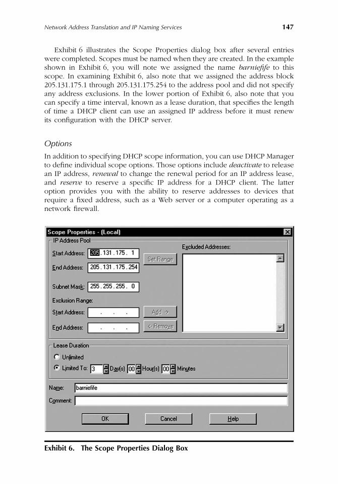
Network Address Translation and IP Naming Services
147
Exhibit 6 illustrates the Scope Properties dialog box after several entrieswere completed. Scopes must be named when they are created. In the exampleshown in Exhibit 6, you will note we assigned the name
barniefife
to thisscope. In examining Exhibit 6, also note that we assigned the address block205.131.175.1 through 205.131.175.254 to the address pool and did not specifyany address exclusions. In the lower portion of Exhibit 6, also note that youcan specify a time interval, known as a lease duration, that specifies the lengthof time a DHCP client can use an assigned IP address before it must renewits configuration with the DHCP server.
Options
In addition to specifying DHCP scope information, you can use DHCP Managerto define individual scope options. Those options include
deactivate
to releasean IP address,
renewal
to change the renewal period for an IP address lease,and
reserve
to reserve a specific IP address for a DHCP client. The latteroption provides you with the ability to reserve addresses to devices thatrequire a fixed address, such as a Web server or a computer operating as anetwork firewall.
Exhibit 6. The Scope Properties Dialog Box
AU1144_ch07_fm Page 147 Thursday, October 11, 2001 1:31 PM
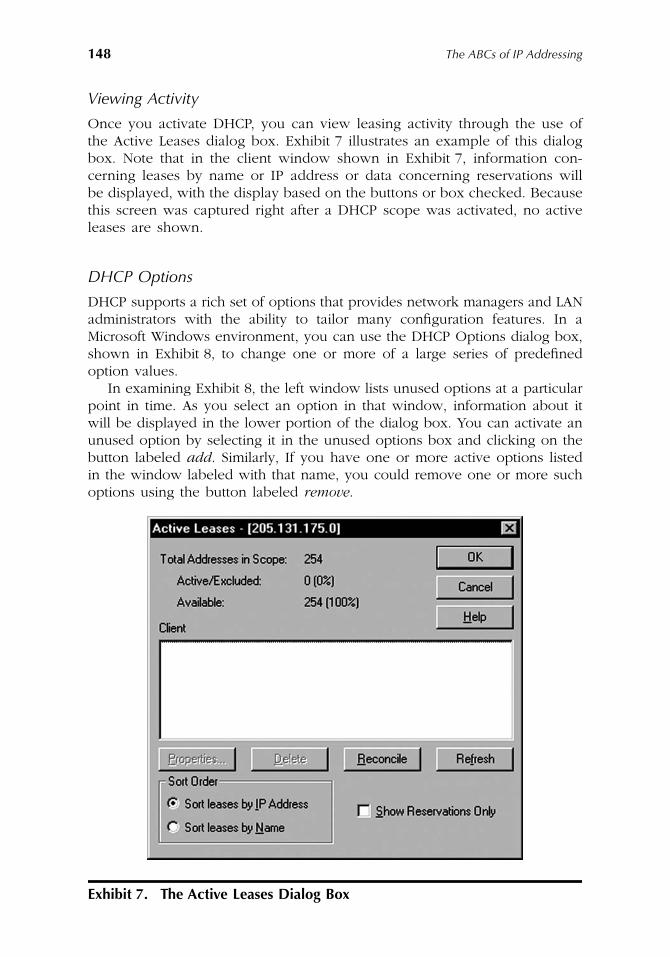
148
The ABCs of IP Addressing
Viewing Activity
Once you activate DHCP, you can view leasing activity through the use ofthe Active Leases dialog box. Exhibit 7 illustrates an example of this dialogbox. Note that in the client window shown in Exhibit 7, information con-cerning leases by name or IP address or data concerning reservations willbe displayed, with the display based on the buttons or box checked. Becausethis screen was captured right after a DHCP scope was activated, no activeleases are shown.
DHCP Options
DHCP supports a rich set of options that provides network managers and LANadministrators with the ability to tailor many configuration features. In aMicrosoft Windows environment, you can use the DHCP Options dialog box,shown in Exhibit 8, to change one or more of a large series of predefinedoption values.
In examining Exhibit 8, the left window lists unused options at a particularpoint in time. As you select an option in that window, information about itwill be displayed in the lower portion of the dialog box. You can activate anunused option by selecting it in the unused options box and clicking on thebutton labeled
add
. Similarly, If you have one or more active options listedin the window labeled with that name, you could remove one or more suchoptions using the button labeled
remove
.
Exhibit 7. The Active Leases Dialog Box
AU1144_ch07_fm Page 148 Thursday, October 11, 2001 1:31 PM
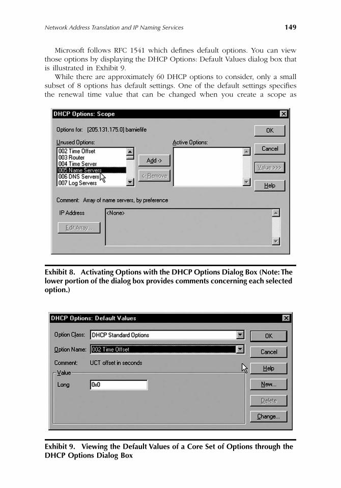
Network Address Translation and IP Naming Services
149
Microsoft follows RFC 1541 which defines default options. You can viewthose options by displaying the DHCP Options: Default Values dialog box thatis illustrated in Exhibit 9.
While there are approximately 60 DHCP options to consider, only a smallsubset of 8 options has default settings. One of the default settings specifiesthe renewal time value that can be changed when you create a scope as
Exhibit 8. Activating Options with the DHCP Options Dialog Box (Note: The lower portion of the dialog box provides comments concerning each selected option.)
Exhibit 9. Viewing the Default Values of a Core Set of Options through the DHCP Options Dialog Box
AU1144_ch07_fm Page 149 Thursday, October 11, 2001 1:31 PM
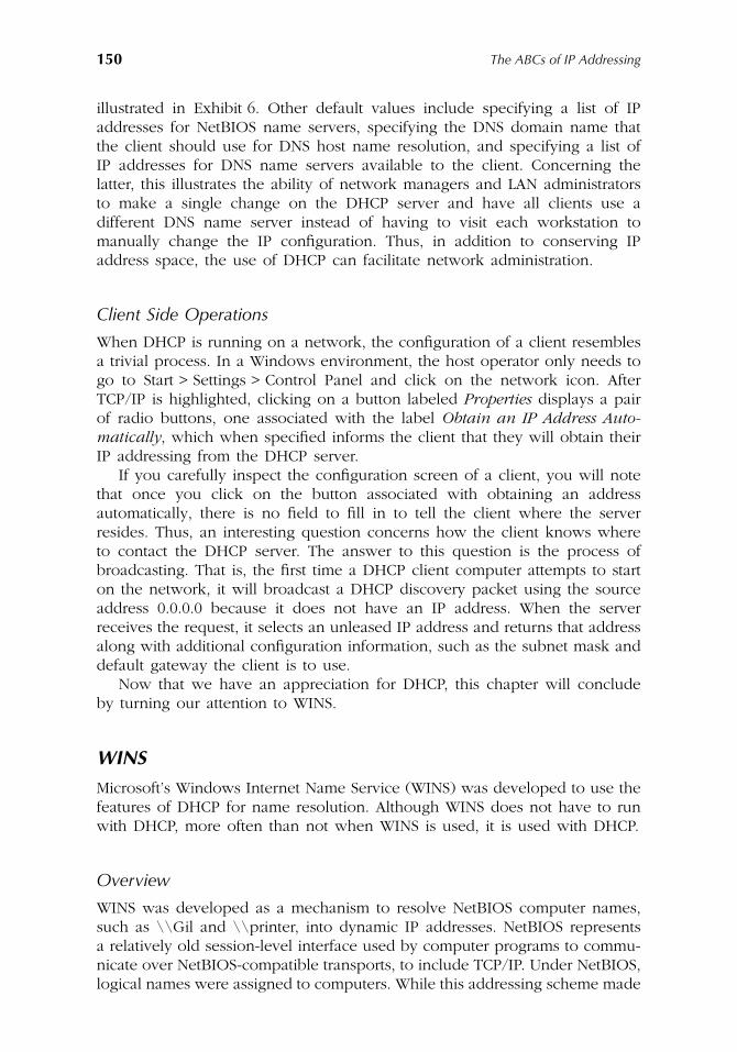
150
The ABCs of IP Addressing
illustrated in Exhibit 6. Other default values include specifying a list of IPaddresses for NetBIOS name servers, specifying the DNS domain name thatthe client should use for DNS host name resolution, and specifying a list ofIP addresses for DNS name servers available to the client. Concerning thelatter, this illustrates the ability of network managers and LAN administratorsto make a single change on the DHCP server and have all clients use adifferent DNS name server instead of having to visit each workstation tomanually change the IP configuration. Thus, in addition to conserving IPaddress space, the use of DHCP can facilitate network administration.
Client Side Operations
When DHCP is running on a network, the configuration of a client resemblesa trivial process. In a Windows environment, the host operator only needs togo to Start > Settings > Control Panel and click on the network icon. AfterTCP/IP is highlighted, clicking on a button labeled
Properties
displays a pairof radio buttons, one associated with the label
Obtain an IP Address Auto-matically
, which when specified informs the client that they will obtain theirIP addressing from the DHCP server.
If you carefully inspect the configuration screen of a client, you will notethat once you click on the button associated with obtaining an addressautomatically, there is no field to fill in to tell the client where the serverresides. Thus, an interesting question concerns how the client knows whereto contact the DHCP server. The answer to this question is the process ofbroadcasting. That is, the first time a DHCP client computer attempts to starton the network, it will broadcast a DHCP discovery packet using the sourceaddress 0.0.0.0 because it does not have an IP address. When the serverreceives the request, it selects an unleased IP address and returns that addressalong with additional configuration information, such as the subnet mask anddefault gateway the client is to use.
Now that we have an appreciation for DHCP, this chapter will concludeby turning our attention to WINS.
WINS
Microsoft’s Windows Internet Name Service (WINS) was developed to use thefeatures of DHCP for name resolution. Although WINS does not have to runwith DHCP, more often than not when WINS is used, it is used with DHCP.
Overview
WINS was developed as a mechanism to resolve NetBIOS computer names,such as \\Gil and \\printer, into dynamic IP addresses. NetBIOS representsa relatively old session-level interface used by computer programs to commu-nicate over NetBIOS-compatible transports, to include TCP/IP. Under NetBIOS,logical names were assigned to computers. While this addressing scheme made
AU1144_ch07_fm Page 150 Thursday, October 11, 2001 1:31 PM
Network Address Translation and IP Naming Services
151
life simple for small networks that represented an isolated island in today’sscheme of interconnectivity, it also precluded the use of the naming schemeto be used in a TCP/IP environment, resulting in the development of WINSto provide a translation process that converts computer names into IPaddresses. In actuality WINS represents one of several methods that can beused to resolve NetBIOS computer names into IP addresses. You can use staticmapping files, such as LMHOSTS, IP broadcast, or a NetBIOS name serverthat in a Windows NT or Windows 2000 network environment is the MicrosoftWINS server.
Server Operation
Similar to DHCP, under Windows NT and Windows 2000, you would installWINS Manager on a server to support WINS.
WINS servers employ a replicated database, which contains NetBIOS com-puter names and IP address mappings. As clients begin to log on to thenetwork, they transmit their computer name and obtain an IP address undera process we will review when discussing client side operations later in thissection. During the log-on process, the WINS server database is updated, whichprovides the ability to replicate database updates among multiple WINS serversthat might be required to support large networks. When multiple WINS serversare configured for use, each server is configured as a
push
or
pull
partner ofat least one other WINS server, with the configuration governing the mannerby which database replication occurs. Microsoft’s detailed guide to WINS shouldbe referenced if you require multiple WINS servers on a network.
Client Operations
Unlike the configuration process involved in setting up a host to use DHCPthat requires a simple click on a radio button, the configuration process tosupport WINS is a bit more involved. To illustrate this, consider Exhibit 10,which illustrates an example of how you would enable the use of WINS ona Windows 95 workstation. In this example, note that we added the IPaddresses for two WINS servers. A WINS client will perform a NetBIOScomputer name-to-IP address mapping resolution process by using NetBIOSover TCP/IP (NetBT) with the first address configured. If the resolution timesout, the next address will be used. Thus, while a bit more demanding thanthe configuration process for a host to use DHCP, the configuration of a clientto use WINS is still a relatively simple process.
When a WINS-enabled computer contacts a WINS server, it will register itsname using a name registration request message. The WINS server will checkits database to ensure the name request is unique and respond with either apositive or negative name registration response. Assuming the registration isgranted, the client must attempt to renew their registration prior to when atime-to-live value configured on the server expires. In fact, a WINS client willattempt to refresh its name registration after one-half of the time-to-liveduration is expired. If the client does not receive a name refresh response
AU1144_ch07_fm Page 151 Thursday, October 11, 2001 1:31 PM
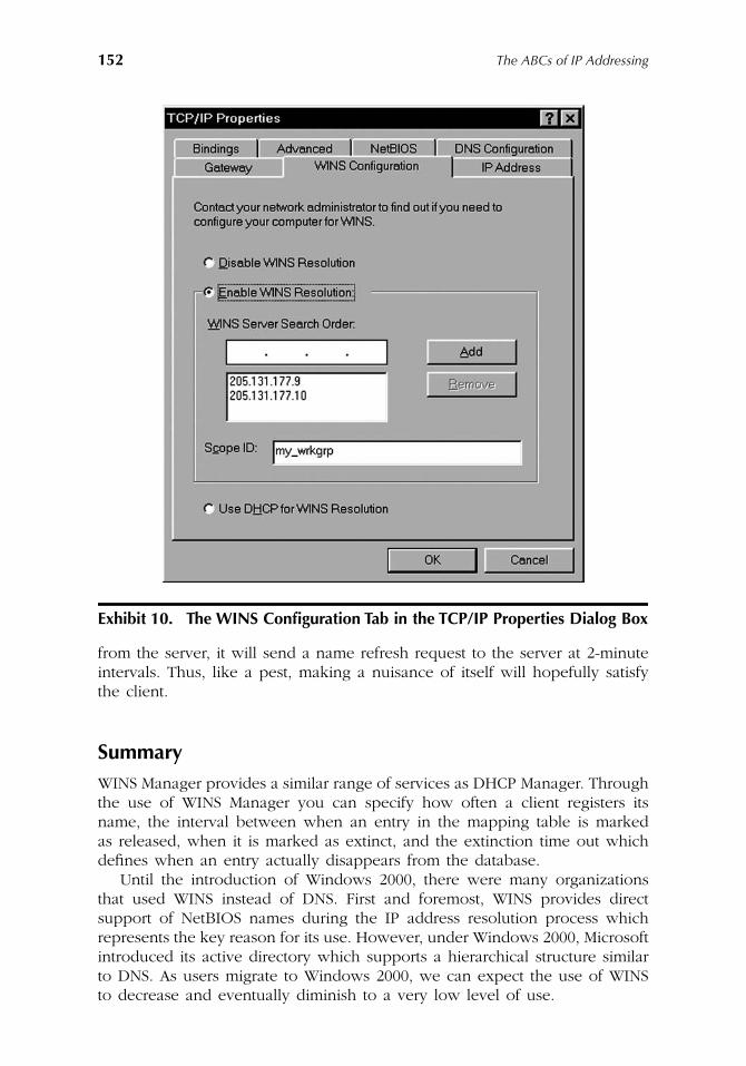
152
The ABCs of IP Addressing
from the server, it will send a name refresh request to the server at 2-minuteintervals. Thus, like a pest, making a nuisance of itself will hopefully satisfythe client.
Summary
WINS Manager provides a similar range of services as DHCP Manager. Throughthe use of WINS Manager you can specify how often a client registers itsname, the interval between when an entry in the mapping table is markedas released, when it is marked as extinct, and the extinction time out whichdefines when an entry actually disappears from the database.
Until the introduction of Windows 2000, there were many organizationsthat used WINS instead of DNS. First and foremost, WINS provides directsupport of NetBIOS names during the IP address resolution process whichrepresents the key reason for its use. However, under Windows 2000, Microsoftintroduced its active directory which supports a hierarchical structure similarto DNS. As users migrate to Windows 2000, we can expect the use of WINSto decrease and eventually diminish to a very low level of use.
Exhibit 10. The WINS Configuration Tab in the TCP/IP Properties Dialog Box
AU1144_ch07_fm Page 152 Thursday, October 11, 2001 1:31 PM
153
Chapter 8
Working with IPv6
Chapter 8 will focus on a technology formerly referred to as the InternetProtocol Next Generation or Ipng. Over a considerable period of time, Ipngevolved from a mechanism designed to increase IP address space to a newIP developed to facilitate routing, security, and the addition of functionalitywithout a requirement to again revise the protocol.
As noted earlier in this book, the near exponential growth in the use ofthe Internet has rapidly depleted the quantity of available IP network addressesand has resulted in such addresses becoming a precious commodity. As weturn our attention to IPv6, we will also note that its addressing capabilityensures that every man, woman, and child on the planet as well as everyelectronic device can obtain an IPv6 address. This capability provides amechanism to enable the development of intelligent network-based homeappliances and other devices that could be managed by a service organizationor the homeowner from their office. Thus, IPv6 can be considered to providea foundation for extending the capabilities of the Internet to new applicationsthat can be expected to arise during the new millennium.
Terminology
Under IPv6, some of the terms we grew acquainted with under IPv4 wererevised. In addition, IPv6 introduces a few new terms. While we will tempo-rarily become IPv6
purists
and examine the terminology associated with thenew protocol in this section, for reasons that will be given shortly, we willrevert to IPv4 terminology in the remainder of this book.
In this section, five terms and what they mean or reference under IPv6will be discussed:
AU1144_ch08_fm Page 153 Thursday, October 11, 2001 1:32 PM
154
The ABCs of IP Addressing
�
Packet
— The term packet is used to reference an IPv6 header plus thefollowing payload. If we remember the discussion of IPv4 presented earlierin this book, we used the term datagram to reference an IPv4 header plusits payload. Therefore, you might wonder why the designers of IPv6switched the term datagram to packet. Were they seeking job securitybecause their managers might now become confused or was there a morerational explanation for the change in nomenclature? The answer to thisquestion resides in the fact that one innovation of IPv6 is its ability totransport traffic from other protocols than the TCP/IP protocol suite. Thus,from a theoretical basis, the term datagram would be inappropriate whenthe IPv6 header transports a payload that does not reside in the TCP/IPprotocol suite and this resulted in the use of the term packet. However,whenever the IPv6 header transports a protocol in the TCP/IP protocolsuite, such as TCP, UDP, and ICMP, the term datagram is still appropriateto use. Because I will restrict my examples to the TCP/IP protocol suite,the term datagram instead of packet will be used.
�
Node
— Under IPv6, the term node is used to represent any device thatsupports IPv6. Therefore, a node can represent a router, server, gateway,or client computer supporting IPv6.
�
Router
— Under IPv6, a router represents a node that forwards packetsnot explicitly addressed to the device.
�
Link
— A link represents a medium over which nodes communicate at thedata link layer. By not defining the medium, this permits a significantdegree of flexibility, enabling IPv6 to be used for mobile wireless andfixed wireless applications.
�
Neighbor
— Under IPv6, a group of nodes attached to the same linkrepresents a neighbor to the other links.
Now that we have an appreciation of the terminology used under IPv6,we will turn our attention to the protocol by examining the IPv6 header.
The IPv6 Header
Exhibit 1 illustrates the IPv6 header. In examining the new header, you willnote a considerable difference when comparing it to the IPv4 header. Althoughthe Version field is common to both headers, once past that field, the similaritybetween IPv4 and IPv6 headers considerably decreases. To obtain an appre-ciation for the differences between the two versions of IP, let us examine eachof the fields within the IPv6 header.
Version Field
Similar to the IPv4 Version field, the IPv6 Version field is 4 bits in length. Asyou might expect, the value of this field is set to 6 (binary 1010) for IPv6.Because the IPv6 Version field is at the beginning of the header, it providesrouters and gateways with a mechanism to rapidly determine the version ofthe IP protocol in use.
AU1144_ch08_fm Page 154 Thursday, October 11, 2001 1:32 PM
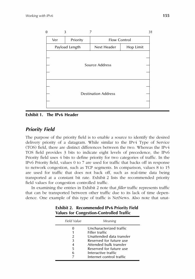
Working with IPv6
155
Priority Field
The purpose of the priority field is to enable a source to identify the desireddelivery priority of a datagram. While similar to the IPv4 Type of Service(TOS) field, there are distinct differences between the two. Whereas the IPv4TOS field provides 3 bits to indicate eight levels of precedence, the IPv6Priority field uses 4 bits to define priority for two categories of traffic. In theIPv6 Priority field, values 0 to 7 are used for traffic that backs off in responseto network congestion, such as TCP segments. In comparison, values 8 to 15are used for traffic that does not back off, such as real-time data beingtransported at a constant bit rate. Exhibit 2 lists the recommended priorityfield values for congestion controlled traffic.
In examining the entries in Exhibit 2 note that
filler
traffic represents trafficthat can be transported between other traffic due to its lack of time depen-dence. One example of this type of traffic is NetNews. Also note that unat-
Exhibit 1. The IPv6 Header
Exhibit 2. Recommended IPv6 Priority Field
Values for Congestion-Controlled Traffic
Field Value Meaning
0 Uncharacterized traffic1 Filler traffic2 Unattended data transfer3 Reserved for future use4 Attended bulk transfer5 Reserved for future use6 Interactive traffic7 Internet control traffic
0 3 7 31
Ver Priority Flow Control
Payload Length Next Header Hop Limit
Source Address
Destination Address
AU1144_ch08_fm Page 155 Thursday, October 11, 2001 1:32 PM
156
The ABCs of IP Addressing
tended data transfer can be e-mail, while attended bulk transfer examplesinclude FTP and HTTP applications. Last but not least, interactive traffic caninclude telnet, while an example of Internet control traffic would be a routingprotocol, such as RIP.
Turning our attention to the second type of traffic governed by the Priorityfield, noncongestion controlled traffic, the lowest priority (8) should be usedfor datagrams that the sender is most willing to have discarded under con-gestion conditions, such as when a video conference is active and congestinga network. In comparison, the highest value (15) should be used for datagramsthat the sender is least willing to have discarded, such as voice-over IP.
Flow Label Field
The Flow Label field is 24 bits in length. This field provides a Quality ofService (QOS) capability, which enables datagrams belonging to a particulartraffic flow to be identified. Thus, a sender can use the Flow Label field inconjunction with the Priority field to convey special handling information.When the value of this field is set to zero, it indicates traffic is not associatedwith a flow. An example of a traffic flow would be datagrams transporting avideoconference, while HTTP and Telnet would represent examples of non-flow traffic.
Payload Length Field
The Payload Length field identifies the length of the datagram following theheader. This field is 16 bits in length and supports a maximum value of 65535,which is also the maximum length of an IPv4 payload.
Next Header Field
The inclusion of a Next Header field represents a considerable improvementto the IPv6 protocol because it provides the foundation for daisy chainoperations. As its name implies, the value of this field identifies the type ofheader following the IPv6 header. The values used for this field are the samevalues supported by the IPv4 Protocol field. Some examples of the NextHeader field values include 1 for ICMP, 6 for TCP, 17 for UDP, and 58 forICMPv6. Because the Next Header field provides the initial mechanism for thedaisy chaining of IPv6 headers, let us examine how this is accomplished priorto resuming our examination of the fields in the IPv6 header.
Exhibit 3 illustrates an example of IPv6 header daisy chaining. In exam-ining Exhibit 3, note that the top portion of the illustration shows IPv6transporting UDP without any additional headers. The middle portion ofExhibit 3 indicates how header chaining can occur. In the middle portion ofExhibit 3, the IPv6 Next Header field indicates that an authentication headerfollows. The authentication header then notes that the next header is the
AU1144_ch08_fm Page 156 Thursday, October 11, 2001 1:32 PM
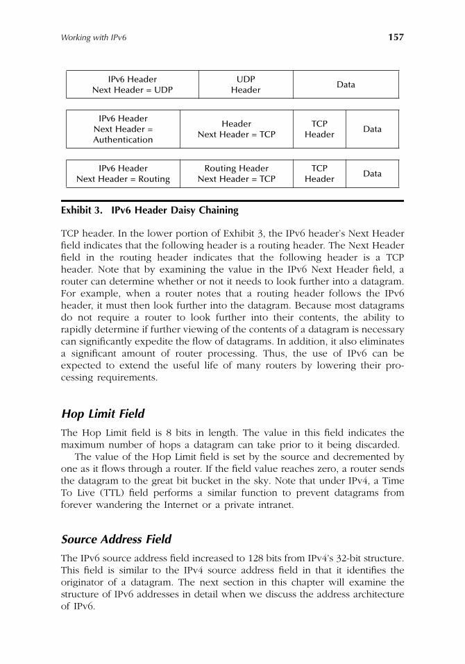
Working with IPv6
157
TCP header. In the lower portion of Exhibit 3, the IPv6 header’s Next Headerfield indicates that the following header is a routing header. The Next Headerfield in the routing header indicates that the following header is a TCPheader. Note that by examining the value in the IPv6 Next Header field, arouter can determine whether or not it needs to look further into a datagram.For example, when a router notes that a routing header follows the IPv6header, it must then look further into the datagram. Because most datagramsdo not require a router to look further into their contents, the ability torapidly determine if further viewing of the contents of a datagram is necessarycan significantly expedite the flow of datagrams. In addition, it also eliminatesa significant amount of router processing. Thus, the use of IPv6 can beexpected to extend the useful life of many routers by lowering their pro-cessing requirements.
Hop Limit Field
The Hop Limit field is 8 bits in length. The value in this field indicates themaximum number of hops a datagram can take prior to it being discarded.
The value of the Hop Limit field is set by the source and decremented byone as it flows through a router. If the field value reaches zero, a router sendsthe datagram to the great bit bucket in the sky. Note that under IPv4, a TimeTo Live (TTL) field performs a similar function to prevent datagrams fromforever wandering the Internet or a private intranet.
Source Address Field
The IPv6 source address field increased to 128 bits from IPv4’s 32-bit structure.This field is similar to the IPv4 source address field in that it identifies theoriginator of a datagram. The next section in this chapter will examine thestructure of IPv6 addresses in detail when we discuss the address architectureof IPv6.
Exhibit 3. IPv6 Header Daisy Chaining
IPv6 HeaderNext Header = UDP
UDPHeader
Data
IPv6 HeaderNext Header =Authentication
HeaderNext Header = TCP
TCPHeader
Data
IPv6 HeaderNext Header = Routing
Routing HeaderNext Header = TCP
TCP Header
Data
AU1144_ch08_fm Page 157 Thursday, October 11, 2001 1:32 PM
158
The ABCs of IP Addressing
Destination Address Field
Similar to the Source Address field, the IPv6 Destination Address field is 128bits in length. This field identifies the intended recipient of a datagram.
Address Architecture
IPv6 is based on the same architecture used in IPv4, resulting in each networkinterface requiring a distinct IP address. The key differences between IPv6and IPv4 with respect to addresses are the manner by which an interface canbe identified and the size and composition of the address. Under IPv6, aninterface can be identified by several addresses to facilitate routing andmanagement. In comparison, under IPv4, an interface can only be assignedone address. Concerning address size, IPv6 uses 128 bits or 96 more bits thanan IPv4 address.
Address Types
IPv6 addresses include unicast and multicast, which were included in IPv4.In addition, IPv6 adds a new address category known as anycast. Althoughan anycast address identifies a group of stations similar to a multicast address,a packet with an anycast address is delivered to only one station, the nearestmember of the group. The use of anycast addressing can be expected tofacilitate network restructuring while minimizing the amount of configurationchanges required to support a new network structure. This is because youcan use an anycast address to reference a group of routers and the alterationof a network when stations use anycast addressing would enable them tocontinue to access the nearest router without a user having to change theaddress configuration of their workstation.
Address Notation
Since IPv6 addresses consist of 128 bits, a mechanism is required to facilitatetheir entry as configuration data. The mechanism used is to replace those bitsby the use of eight 16-bit integers separated by colons, with each integerrepresented by 4 hexadecimal digits. For example, the following representsthe entry of a 128-bit Ipv6 address using hex notation.
6ACD:00001:00FC:B10C:0001:0000:0000:001A
To facilitate the entry of IPv6 addresses, you can skip leading zeros ineach hexadecimal component. That is, write 1 instead of 0001 and 0 insteadof 0000. Thus, this ability to suppress zeros in each hexadecimal componentwould reduce the previous network address to:
6ACD:1:FC:B10C:1:0:0:1A
AU1144_ch08_fm Page 158 Thursday, October 11, 2001 1:32 PM
Working with IPv6
159
Under IPv6, a second method of address simplification was introduced — thedouble-colon (::) convention. Inside an address, a set of consecutive null 16-bit numbers can be replaced by two colons (::). Thus, the previously reducedIP address could be further reduced as:
6ACD:1:FC:B10C:1::1A
It is important to note that the double-colon convention can only be usedonce inside addresses. This is because the reconstruction of the addressrequires the number of integer fields in the address to be subtracted fromeight to determine the number of consecutive fields of zero value the double-colon represents. Otherwise, the use of two or more double-colons wouldcreate ambiguity that would not allow the address to be correctly reconstructed.
Address Allocation
The use of a 128-bit address space provides a high degree of addressassignment flexibility beyond that available under IPv4. IPv6 addressingenables Internet Service Providers to be identified as well as includes theability to identify local and global multicast addresses, private site addressesfor use within an organization, hierarchical geographical global unicastaddresses, and other types of addresses. Exhibit 4 lists the initial allocation ofaddress space under IPv6.
The Internet Assigned Numbers Authority (IANA) was assigned the taskto distribute portions of IPv6 address space to regional registries around theworld, such as the InterNIC in North America, RIPE in Europe, and APNICin Asia. To illustrate the planned use of IPv6 addresses, we will turn ourattention to what will be the most common type of IPv6 address — theprovider based address.
Provider-Based Addresses
The first official distribution of IPv6 addresses will be accomplished throughthe use of provider-based addresses. Based on the initial allocation of IPv6addresses as shown in Exhibit 4, each provider-based address will have the3-bit prefix 010. That prefix will be followed by fields that identify the registrythat allocated the address, the service provider, and the subscriber. The latterfield actually consists of three subfields: (1) a subscriber ID that can representan organization, (2) a variable network and interface identification fields usedin a similar manner to IPv4 network, and (3) host fields. Exhibit 5 illustratesthe initial structure for a provider-based address.
Special Addresses
Under IPv6 there are four special types of unicast addresses that were defined.This section will briefly examine each address.
AU1144_ch08_fm Page 159 Thursday, October 11, 2001 1:32 PM
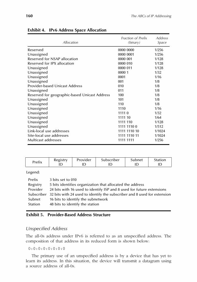
160
The ABCs of IP Addressing
Unspecified Address
The all-0s address under IPv6 is referred to as an unspecified address. Thecomposition of that address in its reduced form is shown below:
0:0:0:0:0:0:0:0
The primary use of an unspecified address is by a device that has yet tolearn its address. In this situation, the device will transmit a datagram usinga source address of all-0s.
Exhibit 4. IPv6 Address Space Allocation
AllocationFraction of Prefix
(binary)Address Space
Reserved 0000 0000 1/256Unassigned 0000 0001 1/256Reserved for NSAP allocation 0000 001 1/128Reserved for IPX allocation 0000 010 1/128Unassigned 0000 011 1/128Unassigned 0000 1 1/32Unassigned 0001 1/16Unassigned 001 1/8Provider-based Unicast Address 010 1/8Unassigned 011 1/8Reserved for geographic-based Unicast Address 100 1/8Unassigned 101 1/8Unassigned 110 1/8Unassigned 1110 1/16Unassigned 1111 0 1/32Unassigned 1111 10 1/64Unassigned 1111 110 1/128Unassigned 1111 1110 0 1/512Link-local use addresses 1111 1110 10 1/1024Site-local use addresses 1111 1110 11 1/1024Multicast addresses 1111 1111 1/256
PrefixRegistry
IDProvider
IDSubscriber
IDSubnet
IDStation
ID
Legend:
Prefix 3 bits set to 010Registry 5 bits identifies organization that allocated the addressProvider 24 bits with 16 used to identify ISP and 8 used for future extensionsSubscriber 32 bits with 24 used to identify the subscriber and 8 used for extensionSubnet 16 bits to identify the subnetworkStation 48 bits to identify the station
Exhibit 5. Provider-Based Address Structure
AU1144_ch08_fm Page 160 Thursday, October 11, 2001 1:32 PM
Working with IPv6
161
Version 6 Loopback
If you remember our discussion of special IPv4 addresses, we noted the useof the 127 Class A network for loopback. Under IPv6, there is only oneloopback address whose composition is noted below:
0:0:0:0:0:0:0:1
Version 4 Addresses
In a mixed IPv4 and IPv6 environment, devices that do not support IPv6 willbe mapped to version 6 addresses using the following form:
0:0:0:0:0:FFFF:w.x.y.z
Here w.x.y.z represents the original IPv4 address. Thus, IPv4 addresses will betransported as IPv6 addresses through the use of the IPv6 version 4 addressformat. This means that an organization with a large number of workstationsand servers connected to the Internet only has to upgrade their router to supportIPv6 addressing when IPv6 is deployed. Then, they can gradually upgrade theirnetwork on a device-by-device basis to obtain an orderly migration to IPv6.
Version 6 Addresses Interfacing V4 Networks
Another special IPv6 address that warrants attention is the address formatused by Version 6 devices communicating with one another across an Ipv4network. Because IPv6 must be transported as IPv4 datagrams, the term IPv4tunneling is used to reference this method.
To support IPv4 tunneling, each IPv6 node attached to an IPv4 networkis assigned an IPv4 address at the interface to the IPv4 network. The IPv6address is then mapped to a special IPv4 compatible IPv6 address format asindicated below:
0:0:0:0:0:0:w.x.y.z
In examining the preceding format, note that the first 96 bits in the IPv6 addressare set to zero, in effect creating an IPv4 address for tunneling purposes.
Although IPv6 is being used on an experimental portion of the Internet,its anticipated movement into a production environment was delayed due tothe more efficient use of existing IPv4 addresses. This occurred via networkaddress translation and the use of DHCP. While the use of IPv6 is less pressingthan thought just a few year ago, no matter how efficient the allocation ofthe remaining IPv4 addresses become, it is a known fact that within the nextfew years all available addresses will be used. Prior to that time, we canexpect a migration to IPv6 to occur.
AU1144_ch08_fm Page 161 Thursday, October 11, 2001 1:32 PM

AU1144_ch08_fm Page 162 Thursday, October 11, 2001 1:32 PM
163
Chapter 9
Network Utility Tools
In this concluding chapter, attention will turn to the operation and utilizationof a core series of network utility tools. The tools we will examine includePing, traceroute, Pathping, nslookup, and ipconfig. While Ping, traceroute,and nslookup are applicable to different operating systems that support aTCP/IP protocol stack, pathping represents a proprietary tool introduced underWindows 2000 and is currently restricted to that operating system.
The network utility tools examined in this chapter were developed toprovide TCP/IP users with a mechanism to isolate problems, determine thelatency through a network, examine the manner by which datagrams arerouted through a network, and determine information about a host name orIP address.
Ping
The Ping utility program is included in every operating system known to meto support the TCP/IP protocol stack. Although many persons associate thename of the program to radar or sonar operations because a ping returnsinformation from a target or destination, another story or legend traces thename to the term packet Internet Grouper. In actuality, Ping was created byMike Muuss of the U.S. Army Research Laboratory in December 1983. Mr.Muuss required a mechanism to determine if various network systems wereoperational. His work initially was commonly used as a verb:
Ping server/gate-way/router to see if it’s up
. Ping is now an Internet standard and is definedin RFC 792.
Regardless of the derivation of the name of the program or whether yourefer to it as a verb or noun, Ping operates by transmitting an ICMP echo-request datagram to a target computer. If the destination machine is oper-ational and supports the TCP/IP protocol stack, it responds with an ICMPecho-response.
AU1144_ch09_fm Page 163 Thursday, October 11, 2001 1:34 PM
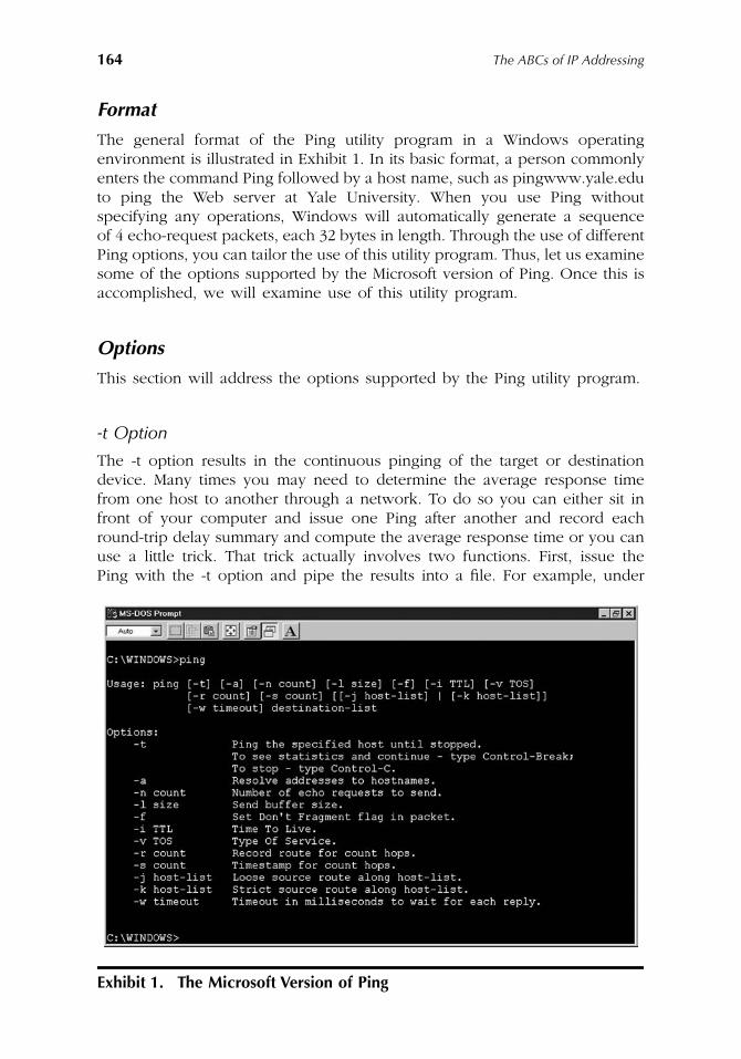
164
The ABCs of IP Addressing
Format
The general format of the Ping utility program in a Windows operatingenvironment is illustrated in Exhibit 1. In its basic format, a person commonlyenters the command Ping followed by a host name, such as pingwww.yale.eduto ping the Web server at Yale University. When you use Ping withoutspecifying any operations, Windows will automatically generate a sequenceof 4 echo-request packets, each 32 bytes in length. Through the use of differentPing options, you can tailor the use of this utility program. Thus, let us examinesome of the options supported by the Microsoft version of Ping. Once this isaccomplished, we will examine use of this utility program.
Options
This section will address the options supported by the Ping utility program.
-t Option
The -t option results in the continuous pinging of the target or destinationdevice. Many times you may need to determine the average response timefrom one host to another through a network. To do so you can either sit infront of your computer and issue one Ping after another and record eachround-trip delay summary and compute the average response time or you canuse a little trick. That trick actually involves two functions. First, issue thePing with the -t option and pipe the results into a file. For example, under
Exhibit 1. The Microsoft Version of Ping
AU1144_ch09_fm Page 164 Thursday, October 11, 2001 1:34 PM
Network Utility Tools
165
Windows you would use the command prompt to enter the following com-mand to continuously Ping the Yale University server and pipe the responsesinto a file named most appropriately pingresponse.
Ping -t www.yale.edu.>pingresponse
After what you feel is a sufficient period of time, enter the multi-key Ctrl-C. You would then import the file into a spreadsheet program, such as Excelor Lotus 123, and manipulate the entries to determine the statistics you require.
-a Option
The -a option results in an IP address being resolved into a hostname. Notethat this is the reverse of the default, since Ping automatically resolves a host-name into an IP address. Concerning the default, a few words of caution arerequired if you intend to use Ping to determine the round-trip delay as a basisfor implementing application. If you use a host name in the command thatwas not previously resolved into an IP address, a DNS name resolution processwill occur. Depending on where in the DNS hierarchy the resolution processobtains the applicable IP address, the time required for the first Ping can bedelayed, whereas subsequent Pings are not. If you limit your Ping operationto typing the command a single time, the first-round trip delay may be higherthan the other three times because Microsoft generates a sequence of fourPings by default. Therefore, in this situation, 25 percent of the response couldbe in error. To remove this potential error, simply issue the Ping commandtwo or more times and discard the first set of results because only that groupwould be adversely affected by the name resolution process.
-n Option
Continuing our examination of Microsoft Ping options, the -n option permitsus to change the number of echo requests that will be transmitted when aPing command is entered. For example, to Ping the Yale University Web servera dozen times, we would use the command as follows:
Ping -n 12 www.yale.edu
-l Option
Through the use of the -l option, you can adjust the length of the datagramstransmitted.
-f and -i Options
The -f option sets the do not fragment flag in the IP header while the -i optionsets the Time to Live (TTL) field value in the IP header. Concerning the latter,
AU1144_ch09_fm Page 165 Thursday, October 11, 2001 1:34 PM
166
The ABCs of IP Addressing
you can set the TTL field to a specific value to determine if routers arediscarding traffic correctly. For example, if a datagram needs to flow throughfive routers on its path from source to destination, you can use Ping withdifferent TTL values to determine if each router on the path is correctly sendingpackets to the great bit bucket in the sky.
-v Option
The -v option can be used to set the Type of Service (TOS) field to a specificvalue. You can use this option as a mechanism to test the priority queuingconfiguration of a router. For example, assume you configured a router toexpedite the flow of datagrams based on the setting of the TOS field in theIP header. You can then transmit multiple data streams through the routeralong with Pings with a predefined TOS setting and analyze the results oftraffic flowing through the router to determine if the queuing method config-ured produces the required results.
-r Option
The -r option when set results in the route of the outbound datagram beingrecorded and returned in the response. A minimum count of one and maximumcount of nine hosts must be specified when this option is used.
-s Option
The -s option results in a timestamp operation being performed for the numberof hops specified when the -r option is used.
-j Option
The -j option provides you with the ability to route datagrams via the list ofhosts specified by host-list. Consecutive hosts can be separated by intermediategateways which results in the term
loose source route
shown in Exhibit 1. Themaximum number of hosts in the host-list is nine.
-k Option
The opposite of a loose source route is a strict source route. Thus, the -koption provides you with a mechanism to specify the route that datagramsshould explicitly follow. Because consecutive hosts cannot be separated byintermediate gateways, the name
strict source route
is used for this option.Similar to the -j option, a maximum of nine hosts can be specified.
AU1144_ch09_fm Page 166 Thursday, October 11, 2001 1:34 PM
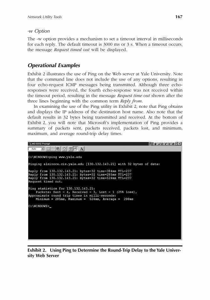
Network Utility Tools
167
-w Option
The -w option provides a mechanism to set a timeout interval in millisecondsfor each reply. The default timeout is 3000 ms or 3 s. When a timeout occurs,the message
Request timed out
will be displayed.
Operational Examples
Exhibit 2 illustrates the use of Ping on the Web server at Yale University. Notethat the command line does not include the use of any options, resulting infour echo-request ICMP messages being transmitted. Although three echo-responses were received, the fourth echo-response was not received withinthe timeout period, resulting in the message
Request time out
shown after thethree lines beginning with the common term
Reply from
.In examining the use of the Ping utility in Exhibit 2, note that Ping obtains
and displays the IP address of the destination host name. Also note that thedefault results in 32 bytes being transmitted and received. At the bottom ofExhibit 2, you will note that Microsoft’s implementation of Ping provides asummary of packets sent, packets received, packets lost, and minimum,maximum, and average round-trip delay times.
Exhibit 2. Using Ping to Determine the Round-Trip Delay to the Yale Univer-sity Web Server
AU1144_ch09_fm Page 167 Thursday, October 11, 2001 1:34 PM
168
The ABCs of IP Addressing
Utilization
One of the key uses of Ping is to ascertain if a destination is operational.However, another use of this utility is to determine if a path to the destinationis available. Thus, if you receive a response to a Ping, you know that a pathto the destination is available and the destination is operational and the TCP/IPprotocol stack at the destination is also operational. Due to the preceding,Ping is commonly used to test equipment installed on a TCP/IP network, i.e.,after you configure the TCP/IP protocol stack on a workstation, you woulduse Ping to ping another station on the network. Upon receipt of one or morereplies, you would then know the TCP/IP protocol stack and the networkconnection of the workstation are operating correctly.
A second common use of Ping is to determine the one-way delay or latencythrough a network. Because Ping measures the round-trip delay, half of thatdelay represents the one-way delay from source to destination. If you anticipatethe addition of a real-time application, such as voice over IP (VoIP) via theInternet or a private intranet, you should consider using Ping prior to imple-menting the application because Ping can inform you as to whether or not theapplication is suitable for use. A VoIP application cannot tolerate a delay greaterthan approximately 250 ms. Therefore, when the delay exceeds that time, itbecomes difficult for persons having a conversation to know when the otherparty actually stopped talking, resulting in both parties frequently beginning totalk at the same time. Then use of the term
over
is required as a mechanismfor one person to tell the other that it is their turn to talk. Obviously, thissituation would not represent a viable mechanism for a business call.
Using Multiple Options
To conclude examination of the operation of Ping, we will discuss the use ofmultiple command options. Exhibit 3 illustrates the use of the -n and -l optionson one command line. In this example, the -n option was suffixed with avalue of 8 to generate eight echo requests, which in this example resulted ineight responses being received. The second option used in the Ping commandline shown in Exhibit 3 is the -l option. This option was used with a valueof 64 as a mechanism to generate 64-byte datagrams. Note the lower portionof the display provides summary statistics for the 8 pings, indicating that theminimum, maximum, and average round-trip delays were 189 ms, 262 ms,and 204 ms, respectively.
For a second example of the use of multiple options in a Ping commandline, we will use the -n and -r options. As previously discussed, the -n optiongoverns the number of pings generated while the -r option results in the routeof up to nine hops being noted. In the example shown in Exhibit 4, I set avalue of 1 for the -n option only because I wanted the results to fit on mydisplay for illustrative purposes. The use of the -r option results in the displayof nine nodes which is the maximum value for this option. From the twomultioption examples, it should be obvious that it is relatively easy to tailorthe use of Ping options to satisfy your particular requirements.
AU1144_ch09_fm Page 168 Thursday, October 11, 2001 1:34 PM
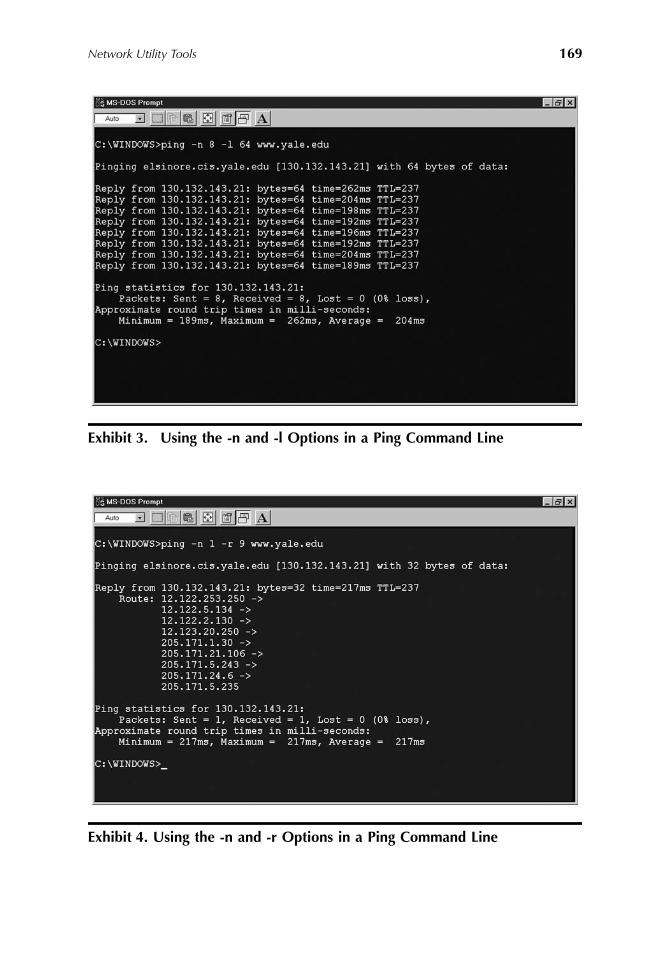
Network Utility Tools
169
Exhibit 3. Using the -n and -l Options in a Ping Command Line
Exhibit 4. Using the -n and -r Options in a Ping Command Line
AU1144_ch09_fm Page 169 Thursday, October 11, 2001 1:34 PM
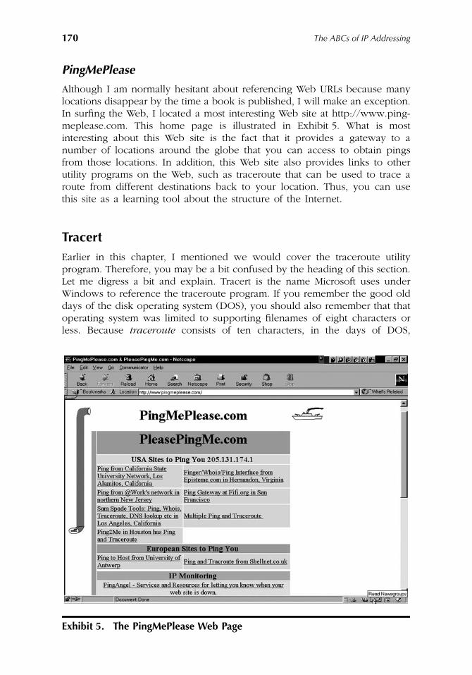
170
The ABCs of IP Addressing
PingMePlease
Although I am normally hesitant about referencing Web URLs because manylocations disappear by the time a book is published, I will make an exception.In surfing the Web, I located a most interesting Web site at http://www.ping-meplease.com. This home page is illustrated in Exhibit 5. What is mostinteresting about this Web site is the fact that it provides a gateway to anumber of locations around the globe that you can access to obtain pingsfrom those locations. In addition, this Web site also provides links to otherutility programs on the Web, such as traceroute that can be used to trace aroute from different destinations back to your location. Thus, you can usethis site as a learning tool about the structure of the Internet.
Tracert
Earlier in this chapter, I mentioned we would cover the traceroute utilityprogram. Therefore, you may be a bit confused by the heading of this section.Let me digress a bit and explain. Tracert is the name Microsoft uses underWindows to reference the traceroute program. If you remember the good olddays of the disk operating system (DOS), you should also remember that thatoperating system was limited to supporting filenames of eight characters orless. Because
traceroute
consists of ten characters, in the days of DOS,
Exhibit 5. The PingMePlease Web Page
AU1144_ch09_fm Page 170 Thursday, October 11, 2001 1:34 PM
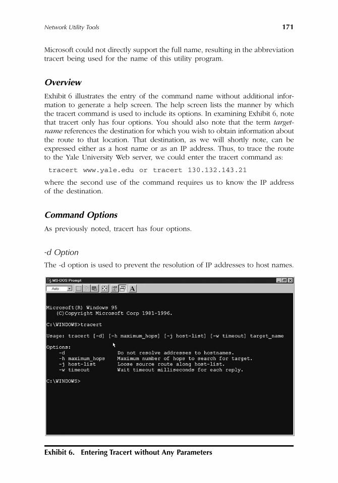
Network Utility Tools
171
Microsoft could not directly support the full name, resulting in the abbreviationtracert being used for the name of this utility program.
Overview
Exhibit 6 illustrates the entry of the command name without additional infor-mation to generate a help screen. The help screen lists the manner by whichthe tracert command is used to include its options. In examining Exhibit 6, notethat tracert only has four options. You should also note that the term
target-name
references the destination for which you wish to obtain information aboutthe route to that location. That destination, as we will shortly note, can beexpressed either as a host name or as an IP address. Thus, to trace the routeto the Yale University Web server, we could enter the tracert command as:
tracert www.yale.edu or tracert 130.132.143.21
where the second use of the command requires us to know the IP addressof the destination.
Command Options
As previously noted, tracert has four options.
-d Option
The -d option is used to prevent the resolution of IP addresses to host names.
Exhibit 6. Entering Tracert without Any Parameters
AU1144_ch09_fm Page 171 Thursday, October 11, 2001 1:34 PM
172
The ABCs of IP Addressing
-h Option
The second option, -h, permits you to specify a maximum number of hopsduring a search of a route to the destination specified as a target name in thecommand. The default value is 30 hops which should be sufficient for almostevery conceivable use of tracert. However, if you need more hops to reacha destination, you can easily use the -h option. For example, assume youcould not reach the Yale University Web server with the default value of 30hops. To change the default setting to 40 hops, you would enter the followingcommand line:
Tracert -h 40 www.yale.edu
-j Option
Continuing our examination of tracert options, the -j option permits you tospecify a loose source route by listing a series of host names.
-w Option
Last but not least, the -w option permits you to specify a timeout value inmilliseconds for each reply. As we will shortly note when examining the useof tracert, this utility program will discover a route by transmitting a sequenceof three datagrams at a time. Thus, if it requires 30 hops to determine a routeto a destination, tracert will generate 90 datagrams. You can then set a timeoutthreshold for each datagram by using the -w option followed by a value inmilliseconds.
Now that we have an appreciation for the options supported by tracert,we will discuss its operation. In doing so, we will first discuss how tracertoperates and then examine the use of the command to trace the route frommy computer to the Yale University Web server.
Operation
As noted during an earlier discussion of the IP header, the Time-To-Live (TTL)field value is decremented by 1 as a datagram flows through a router. If thevalue reaches zero, the router sends the datagram to the great bit bucket inthe sky. In addition, the router will return an ICMP Time Exceeded messageto the originator of the datagram.
Recognizing the manner by which the TTL field functions as a hop counter,the designer of tracert developed the program to send a sequence of datagramswith varying TTL field values, i.e., the tracert program first sets the value ofthe TTL field in the IP header to 1. This results in the first router along thepath to the destination setting the field value to zero, discarding the datagram,and returning an ICMP Time Exceeded message. Thus, the first router alongthe path to the destination has now been determined.
AU1144_ch09_fm Page 172 Thursday, October 11, 2001 1:34 PM
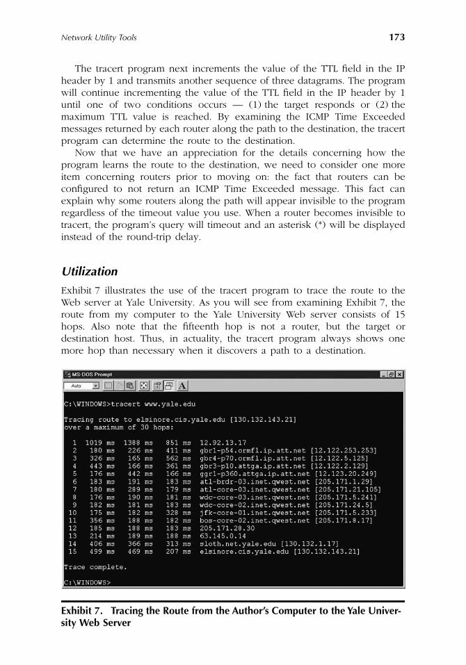
Network Utility Tools
173
The tracert program next increments the value of the TTL field in the IPheader by 1 and transmits another sequence of three datagrams. The programwill continue incrementing the value of the TTL field in the IP header by 1until one of two conditions occurs — (1) the target responds or (2) themaximum TTL value is reached. By examining the ICMP Time Exceededmessages returned by each router along the path to the destination, the tracertprogram can determine the route to the destination.
Now that we have an appreciation for the details concerning how theprogram learns the route to the destination, we need to consider one moreitem concerning routers prior to moving on: the fact that routers can beconfigured to not return an ICMP Time Exceeded message. This fact canexplain why some routers along the path will appear invisible to the programregardless of the timeout value you use. When a router becomes invisible totracert, the program’s query will timeout and an asterisk (*) will be displayedinstead of the round-trip delay.
Utilization
Exhibit 7 illustrates the use of the tracert program to trace the route to theWeb server at Yale University. As you will see from examining Exhibit 7, theroute from my computer to the Yale University Web server consists of 15hops. Also note that the fifteenth hop is not a router, but the target ordestination host. Thus, in actuality, the tracert program always shows onemore hop than necessary when it discovers a path to a destination.
Exhibit 7. Tracing the Route from the Author’s Computer to the Yale Univer-sity Web Server
AU1144_ch09_fm Page 173 Thursday, October 11, 2001 1:34 PM
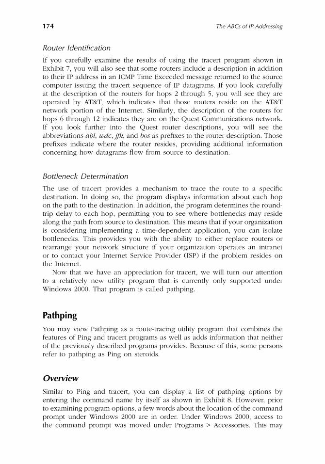
174
The ABCs of IP Addressing
Router Identification
If you carefully examine the results of using the tracert program shown inExhibit 7, you will also see that some routers include a description in additionto their IP address in an ICMP Time Exceeded message returned to the sourcecomputer issuing the tracert sequence of IP datagrams. If you look carefullyat the description of the routers for hops 2 through 5, you will see they areoperated by AT&T, which indicates that those routers reside on the AT&Tnetwork portion of the Internet. Similarly, the description of the routers forhops 6 through 12 indicates they are on the Quest Communications network.If you look further into the Quest router descriptions, you will see theabbreviations
abl
,
wdc
,
jfk
, and
bos
as prefixes to the router description. Thoseprefixes indicate where the router resides, providing additional informationconcerning how datagrams flow from source to destination.
Bottleneck Determination
The use of tracert provides a mechanism to trace the route to a specificdestination. In doing so, the program displays information about each hopon the path to the destination. In addition, the program determines the round-trip delay to each hop, permitting you to see where bottlenecks may residealong the path from source to destination. This means that if your organizationis considering implementing a time-dependent application, you can isolatebottlenecks. This provides you with the ability to either replace routers orrearrange your network structure if your organization operates an intranetor to contact your Internet Service Provider (ISP) if the problem resides onthe Internet.
Now that we have an appreciation for tracert, we will turn our attentionto a relatively new utility program that is currently only supported underWindows 2000. That program is called pathping.
Pathping
You may view Pathping as a route-tracing utility program that combines thefeatures of Ping and tracert programs as well as adds information that neitherof the previously described programs provides. Because of this, some personsrefer to pathping as Ping on steroids.
Overview
Similar to Ping and tracert, you can display a list of pathping options byentering the command name by itself as shown in Exhibit 8. However, priorto examining program options, a few words about the location of the commandprompt under Windows 2000 are in order. Under Windows 2000, access tothe command prompt was moved under Programs > Accessories. This may
AU1144_ch09_fm Page 174 Thursday, October 11, 2001 1:34 PM
Network Utility Tools
175
explain why some persons familiar with the use of the command promptunder other versions of Windows appear to scratch their head for a fewminutes when working with this newer version of Windows.
Now that we know where the command prompt resides under Windows2000, we will discuss pathping command options.
Options
Pathping doubles the number of tracert options, providing users with a totalof eight options to consider. Similar to Ping and tracert, you can simply enterthe command with a target name, resulting in default values being used. Forexample, returning to the Yale University Web server, we can use the pathpingcommand as follows:
Pathping www.yale.edu.
-n Option
The first option shown in Exhibit 8, -n, results in the prevention of theresolution of IP addresses into host names. If you do not select this option,the program will automatically perform a reverse name resolution which addstime to the pathping command execution process.
-h Option
The -h option is used to specify the number of hops to search for the target.Similar to Ping and tracert, the default value is 30 hops.
Exhibit 8. Results of Entering the Command Name Pathping by Itself
AU1144_ch09_fm Page 175 Thursday, October 11, 2001 1:34 PM
176
The ABCs of IP Addressing
-g Option
The -g option provides you with the ability to specify a loose source route.This means the hosts specified can be separated by intermediate gateways.
-p Option
The -p option provides you with the ability to specify the time or period towait between successive pings. The default value is 250 ms or a quarter of asecond.
-q Option
The -q option is used to specify the number of queries transmitted to eachrouter along the route to the destination. The default value for pathping is100, which is significantly greater than the use of four queries under Ping andthree queries per router under tracert. While the default value of 100 is asignificant improvement when you require a statistical average with a smallstandard deviation, it is important to note that the -p and -q options alongwith the number of hops required to reach a target can result in an extremelylong time for the program to fully execute. For example, if the number ofhops to reach the target is 20 and the default value of the -q option of 100is retained, the program will generate 20
×
100 or 2000 queries. If you setthe value of the -p option to 12 to wait 3 seconds between pings, the totalduration becomes 2000 queries
×
3 seconds per query or 6000 seconds whichis 100 minutes. Thus, you should carefully consider the values for the -h, -p,and -q options as an entity.
-T Option
The -T option results in the attachment of a Layer 2 (Media Access Control)priority tag to each ping packet transmitted to each of the network devicesalong the route to the destination. You would use this option as a mechanismto identify network devices that do not support or do not have Layer 2 priorityenabled. Unlike preceding options that can be upper or lower case, the -Toption must be capitalized.
-R Option
The last option supported by pathping is the -R option. This option can beused to determine whether or not each device along the route to the destinationsupports the Resource Reservation Protocol (RSVP). This option enables youto determine if it is possible to obtain reserved bandwidth between sourceand destination to support an application requiring a Quality of Service (QOS)function. Similar to the -T option, the -R option must also be capitalized.
Now that we have reviewed pathping options, we will discuss its operation.
AU1144_ch09_fm Page 176 Thursday, October 11, 2001 1:34 PM
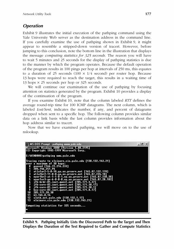
Network Utility Tools
177
Operation
Exhibit 9 illustrates the initial execution of the pathping command using theYale University Web server as the destination address in the command line.If you carefully examine the use of pathping shown in Exhibit 9, it mightappear to resemble a stripped-down version of tracert. However, beforejumping to this conclusion, note the bottom line in the illustration that displaysthe message
computing statistics for 325 seconds
. The reason you will haveto wait 5 minutes and 25 seconds for the display of pathping statistics is dueto the manner by which the program operates. Because the default operationof the program results in 100 pings per hop at intervals of 250 ms, this equatesto a duration of 25 seconds (100
×
1/4 second) per router hop. Because13 hops were required to reach the target, this results in a waiting time of13 hops
×
25 seconds per hop or 325 seconds.We will continue our examination of the use of pathping by focusing
attention on statistics generated by the program. Exhibit 10 provides a displayof the continuation of the program.
If you examine Exhibit 10, note that the column labeled
RTT
defines theaverage round-trip time for 100 ICMP datagrams. The next column, which islabeled
Lost/Sent
, indicates the number, if any, and percent of datagramsdropped when sent to a specific hop. The following column provides similardata on a link basis while the last column provides information about thehop address similar to tracert.
Now that we have examined pathping, we will move on to the use ofnslookup.
Exhibit 9. Pathping Initially Lists the Discovered Path to the Target and Then Displays the Duration of the Test Required to Gather and Compute Statistics
AU1144_ch09_fm Page 177 Thursday, October 11, 2001 1:34 PM
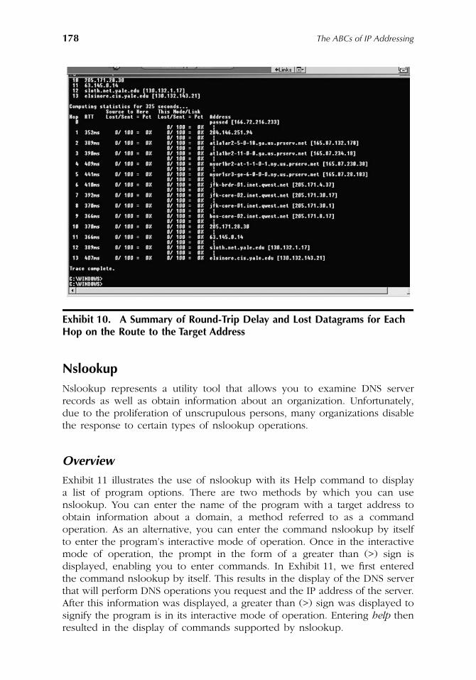
178 The ABCs of IP Addressing
NslookupNslookup represents a utility tool that allows you to examine DNS serverrecords as well as obtain information about an organization. Unfortunately,due to the proliferation of unscrupulous persons, many organizations disablethe response to certain types of nslookup operations.
Overview
Exhibit 11 illustrates the use of nslookup with its Help command to displaya list of program options. There are two methods by which you can usenslookup. You can enter the name of the program with a target address toobtain information about a domain, a method referred to as a commandoperation. As an alternative, you can enter the command nslookup by itselfto enter the program’s interactive mode of operation. Once in the interactivemode of operation, the prompt in the form of a greater than (>) sign isdisplayed, enabling you to enter commands. In Exhibit 11, we first enteredthe command nslookup by itself. This results in the display of the DNS serverthat will perform DNS operations you request and the IP address of the server.After this information was displayed, a greater than (>) sign was displayed tosignify the program is in its interactive mode of operation. Entering help thenresulted in the display of commands supported by nslookup.
Exhibit 10. A Summary of Round-Trip Delay and Lost Datagrams for Each Hop on the Route to the Target Address
AU1144_ch09_fm Page 178 Thursday, October 11, 2001 1:34 PM
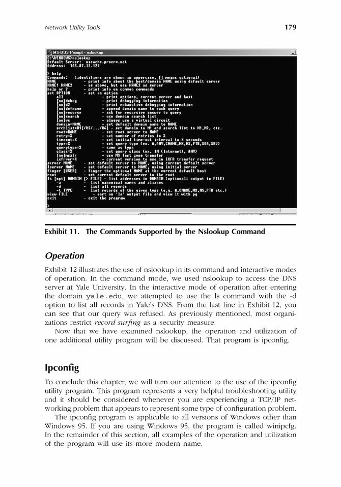
Network Utility Tools 179
Operation
Exhibit 12 illustrates the use of nslookup in its command and interactive modesof operation. In the command mode, we used nslookup to access the DNSserver at Yale University. In the interactive mode of operation after enteringthe domain yale.edu, we attempted to use the ls command with the -doption to list all records in Yale’s DNS. From the last line in Exhibit 12, youcan see that our query was refused. As previously mentioned, most organi-zations restrict record surfing as a security measure.
Now that we have examined nslookup, the operation and utilization ofone additional utility program will be discussed. That program is ipconfig.
IpconfigTo conclude this chapter, we will turn our attention to the use of the ipconfigutility program. This program represents a very helpful troubleshooting utilityand it should be considered whenever you are experiencing a TCP/IP net-working problem that appears to represent some type of configuration problem.
The ipconfig program is applicable to all versions of Windows other thanWindows 95. If you are using Windows 95, the program is called winipcfg.In the remainder of this section, all examples of the operation and utilizationof the program will use its more modern name.
Exhibit 11. The Commands Supported by the Nslookup Command
AU1144_ch09_fm Page 179 Thursday, October 11, 2001 1:34 PM
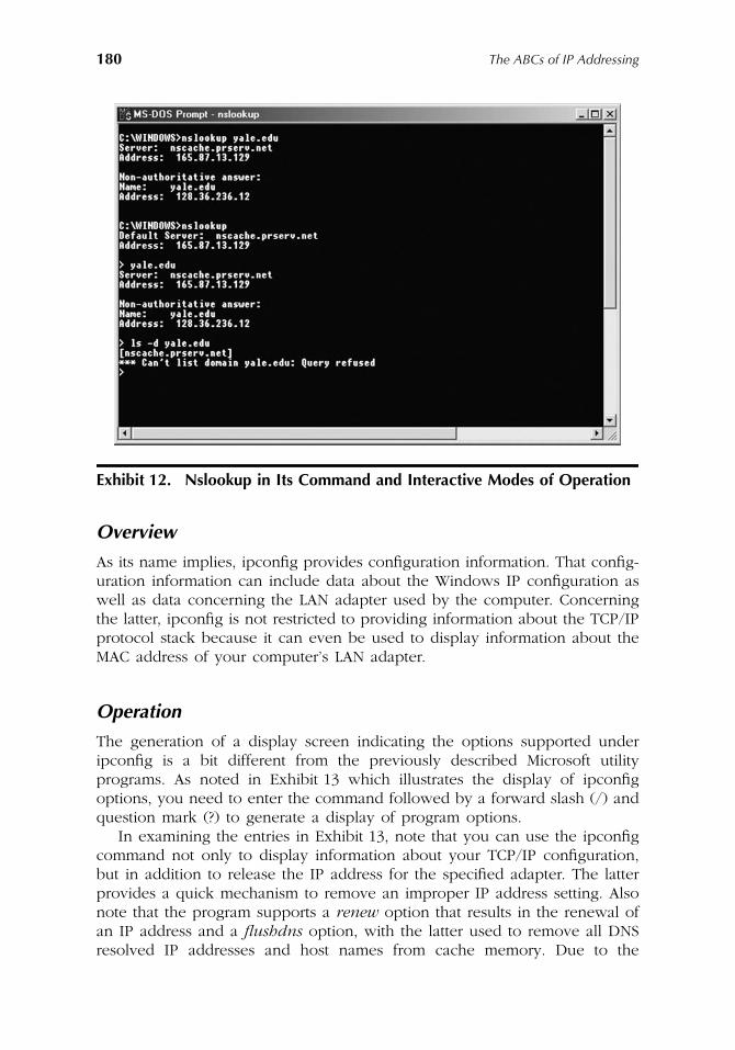
180 The ABCs of IP Addressing
Overview
As its name implies, ipconfig provides configuration information. That config-uration information can include data about the Windows IP configuration aswell as data concerning the LAN adapter used by the computer. Concerningthe latter, ipconfig is not restricted to providing information about the TCP/IPprotocol stack because it can even be used to display information about theMAC address of your computer’s LAN adapter.
Operation
The generation of a display screen indicating the options supported underipconfig is a bit different from the previously described Microsoft utilityprograms. As noted in Exhibit 13 which illustrates the display of ipconfigoptions, you need to enter the command followed by a forward slash (/) andquestion mark (?) to generate a display of program options.
In examining the entries in Exhibit 13, note that you can use the ipconfigcommand not only to display information about your TCP/IP configuration,but in addition to release the IP address for the specified adapter. The latterprovides a quick mechanism to remove an improper IP address setting. Alsonote that the program supports a renew option that results in the renewal ofan IP address and a flushdns option, with the latter used to remove all DNSresolved IP addresses and host names from cache memory. Due to the
Exhibit 12. Nslookup in Its Command and Interactive Modes of Operation
AU1144_ch09_fm Page 180 Thursday, October 11, 2001 1:34 PM
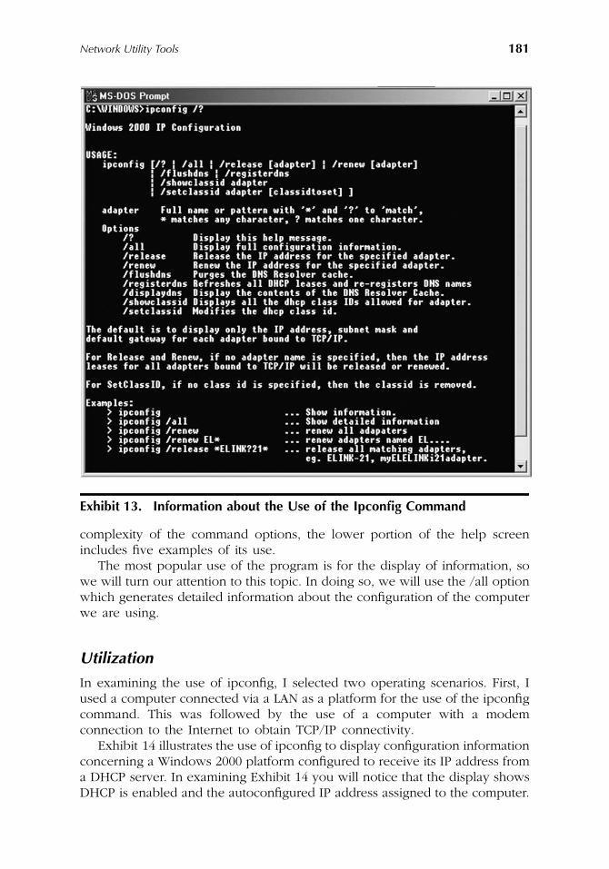
Network Utility Tools 181
complexity of the command options, the lower portion of the help screenincludes five examples of its use.
The most popular use of the program is for the display of information, sowe will turn our attention to this topic. In doing so, we will use the /all optionwhich generates detailed information about the configuration of the computerwe are using.
Utilization
In examining the use of ipconfig, I selected two operating scenarios. First, Iused a computer connected via a LAN as a platform for the use of the ipconfigcommand. This was followed by the use of a computer with a modemconnection to the Internet to obtain TCP/IP connectivity.
Exhibit 14 illustrates the use of ipconfig to display configuration informationconcerning a Windows 2000 platform configured to receive its IP address froma DHCP server. In examining Exhibit 14 you will notice that the display showsDHCP is enabled and the autoconfigured IP address assigned to the computer.
Exhibit 13. Information about the Use of the Ipconfig Command
AU1144_ch09_fm Page 181 Thursday, October 11, 2001 1:34 PM
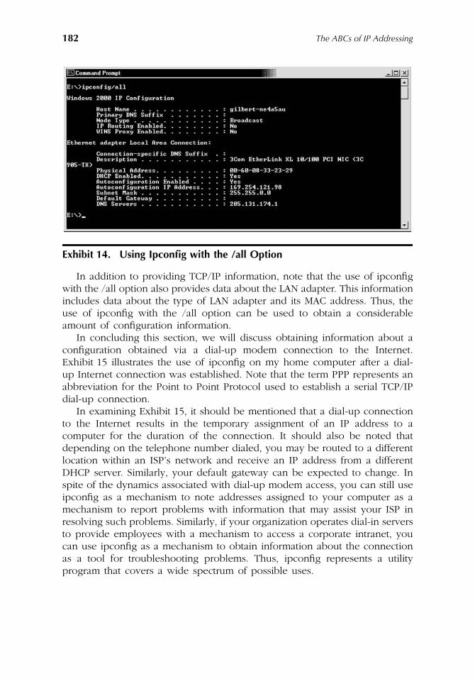
182 The ABCs of IP Addressing
In addition to providing TCP/IP information, note that the use of ipconfigwith the /all option also provides data about the LAN adapter. This informationincludes data about the type of LAN adapter and its MAC address. Thus, theuse of ipconfig with the /all option can be used to obtain a considerableamount of configuration information.
In concluding this section, we will discuss obtaining information about aconfiguration obtained via a dial-up modem connection to the Internet.Exhibit 15 illustrates the use of ipconfig on my home computer after a dial-up Internet connection was established. Note that the term PPP represents anabbreviation for the Point to Point Protocol used to establish a serial TCP/IPdial-up connection.
In examining Exhibit 15, it should be mentioned that a dial-up connectionto the Internet results in the temporary assignment of an IP address to acomputer for the duration of the connection. It should also be noted thatdepending on the telephone number dialed, you may be routed to a differentlocation within an ISP’s network and receive an IP address from a differentDHCP server. Similarly, your default gateway can be expected to change. Inspite of the dynamics associated with dial-up modem access, you can still useipconfig as a mechanism to note addresses assigned to your computer as amechanism to report problems with information that may assist your ISP inresolving such problems. Similarly, if your organization operates dial-in serversto provide employees with a mechanism to access a corporate intranet, youcan use ipconfig as a mechanism to obtain information about the connectionas a tool for troubleshooting problems. Thus, ipconfig represents a utilityprogram that covers a wide spectrum of possible uses.
Exhibit 14. Using Ipconfig with the /all Option
AU1144_ch09_fm Page 182 Thursday, October 11, 2001 1:34 PM
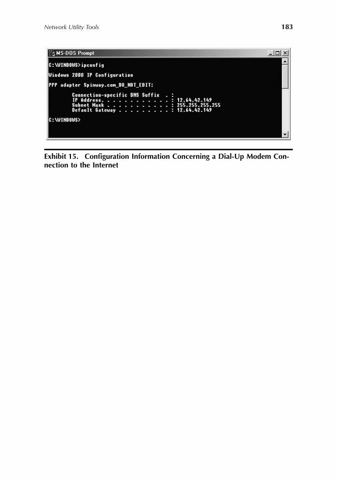
Network Utility Tools 183
Exhibit 15. Configuration Information Concerning a Dial-Up Modem Con-nection to the Internet
AU1144_ch09_fm Page 183 Thursday, October 11, 2001 1:34 PM

AU1144_ch09_fm Page 184 Thursday, October 11, 2001 1:34 PM
185
Index
A
ACK bit, 47, 51–52Acknowledgment Number field, 46Active OPEN function call, 50Address Resolution Protocol (ARP), 16, 17, 20, 34
address location, 35ARP cache, 34gratuitous ARP, 35–36packet fields, 34–35Proxy ARP (ARP Hack), 36Reverse Address Resolution Protocol (RARP),
34, 36Address space availability, 3–4, 62, 137Address spoofing, 8, 85, 88, 89, 90–91
countermeasures, 85, 90–91Address translation,
See
Address Resolution Protocol; Network Address Translation
Advanced Research Projects Agency (ARPA), 80Advanced TCP/IP Settings, 104–108All ones, 86
anti-spoofing, 90subnets, 100
All-stations group address, 128–129All zeros, 85, 86
anti-spoofing, 90IPv6 unspecified address, 160subnets, 100
Anti-spoofing techniques, 85, 90–91,
See
also
Address spoofing
Anycast addressing, 158Application layer, 15, 19ARP,
See
Address Resolution ProtocolARPAnet, 32
datagram transmission, 20–21DNS history, 73
ARP Hack, 36Authentication header, 156–157
B
Binary numbers, 62–64BOOTP, 145Broadcast addresses, 86–89, 113–114, 124Broadcasts to networks, 86–88Bytes, 22
C
Checksum, 31, 48, 58CIDR,
See
Classless Inter-Domain RoutingClass A IP address, 17, 31, 66–67, 111
management and performance issues, 96prefix method of address reference, 111–112subnets,
See
Subnettingusing third and fourth bytes for subnetting,
115–116Class B IP address, 17, 31, 66, 67–68
management and performance issues, 96prefix method of address reference, 111–112subnets,
See
Subnettingusing third and fourth bytes for subnetting,
115–116Class C IP address, 17, 31, 66, 68
prefix method of address reference, 111–112using fourth byte for subnetting, 115–116
Class D IP addresses, 31, 66, 68–69, 123, 125–126,
See
also
Multicastingreserved addresses, 126
Class E IP addresses, 31, 66, 69Classful addressing, 17, 31, 66–69,
See
also
specific
classes
CIDR,
See
Classless Inter-Domain Routingprefix method, 111–112, 118, 119
Classless inter-domain routing (CIDR), 8, 117–123
address allocation, 120–121
AU1144_index_fm Page 185 Thursday, October 11, 2001 1:35 PM
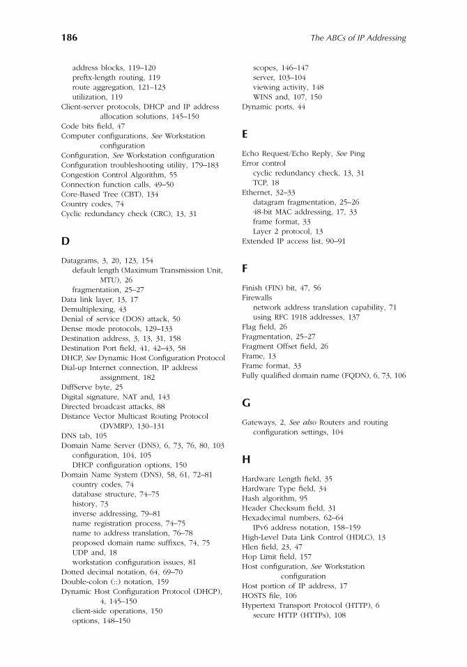
186
The ABCs of IP Addressing
address blocks, 119–120prefix-length routing, 119route aggregation, 121–123utilization, 119
Client-server protocols, DHCP and IP address allocation solutions, 145–150
Code bits field, 47Computer configurations,
See
Workstation configuration
Configuration,
See
Workstation configurationConfiguration troubleshooting utility, 179–183Congestion Control Algorithm, 55Connection function calls, 49–50Core-Based Tree (CBT), 134Country codes, 74Cyclic redundancy check (CRC), 13, 31
D
Datagrams, 3, 20, 123, 154default length (Maximum Transmission Unit,
MTU), 26fragmentation, 25–27
Data link layer, 13, 17Demultiplexing, 43Denial of service (DOS) attack, 50Dense mode protocols, 129–133Destination address, 3, 13, 31, 158Destination Port field, 41, 42–43, 58DHCP,
See
Dynamic Host Configuration ProtocolDial-up Internet connection, IP address
assignment, 182DiffServe byte, 25Digital signature, NAT and, 143Directed broadcast attacks, 88Distance Vector Multicast Routing Protocol
(DVMRP), 130–131DNS tab, 105Domain Name Server (DNS), 6, 73, 76, 80, 103
configuration, 104, 105DHCP configuration options, 150
Domain Name System (DNS), 58, 61, 72–81country codes, 74database structure, 74–75history, 73inverse addressing, 79–81name registration process, 74–75name to address translation, 76–78proposed domain name suffixes, 74, 75UDP and, 18workstation configuration issues, 81
Dotted decimal notation, 64, 69–70Double-colon (::) notation, 159Dynamic Host Configuration Protocol (DHCP),
4, 145–150client-side operations, 150options, 148–150
scopes, 146–147server, 103–104viewing activity, 148WINS and, 107, 150
Dynamic ports, 44
E
Echo Request/Echo Reply,
See
PingError control
cyclic redundancy check, 13, 31TCP, 18
Ethernet, 32–33datagram fragmentation, 25–2648-bit MAC addressing, 17, 33frame format, 33Layer 2 protocol, 13
Extended IP access list, 90–91
F
Finish (FIN) bit, 47, 56Firewalls
network address translation capability, 71using RFC 1918 addresses, 137
Flag field, 26Fragmentation, 25–27Fragment Offset field, 26Frame, 13Frame format, 33Fully qualified domain name (FQDN), 6, 73, 106
G
Gateways, 2,
See
also
Routers and routingconfiguration settings, 104
H
Hardware Length field, 35Hardware Type field, 34Hash algorithm, 95Header Checksum field, 31Hexadecimal numbers, 62–64
IPv6 address notation, 158–159High-Level Data Link Control (HDLC), 13Hlen field, 23, 47Hop Limit field, 157Host configuration,
See
Workstation configuration
Host portion of IP address, 17HOSTS file, 106Hypertext Transport Protocol (HTTP), 6
secure HTTP (HTTPs), 108
AU1144_index_fm Page 186 Thursday, October 11, 2001 1:35 PM
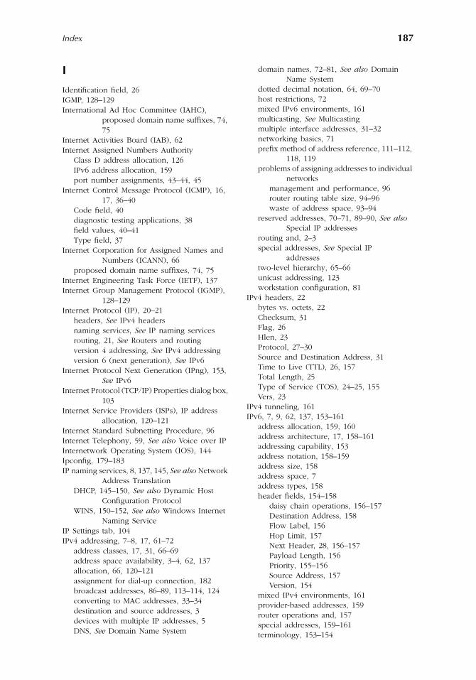
Index
187
I
Identification field, 26IGMP, 128–129International Ad Hoc Committee (IAHC),
proposed domain name suffixes, 74, 75
Internet Activities Board (IAB), 62Internet Assigned Numbers Authority
Class D address allocation, 126IPv6 address allocation, 159port number assignments, 43–44, 45
Internet Control Message Protocol (ICMP), 16, 17, 36–40
Code field, 40diagnostic testing applications, 38field values, 40–41Type field, 37
Internet Corporation for Assigned Names and Numbers (ICANN), 66
proposed domain name suffixes, 74, 75Internet Engineering Task Force (IETF), 137Internet Group Management Protocol (IGMP),
128–129Internet Protocol (IP), 20–21
headers,
See
IPv4 headersnaming service
s
,
See
IP naming servicesrouting, 21,
See
Routers and routingversion 4 addressing,
See
IPv4 addressingversion 6 (next generation),
See
IPv6Internet Protocol Next Generation (IPng), 153,
See
IPv6Internet Protocol (TCP/IP) Properties dialog box,
103Internet Service Providers (ISPs), IP address
allocation, 120–121Internet Standard Subnetting Procedure, 96Internet Telephony, 59,
See
also
Voice over IPInternetwork Operating System (IOS), 144Ipconfig, 179–183IP naming services, 8, 137, 145,
See
also
Network Address Translation
DHCP, 145–150,
See
also
Dynamic Host Configuration Protocol
WINS, 150–152,
See
also
Windows Internet Naming Service
IP Settings tab, 104IPv4 addressing, 7–8, 17, 61–72
address classes, 17, 31, 66–69address space availability, 3–4, 62, 137allocation, 66, 120–121assignment for dial-up connection, 182broadcast addresses, 86–89, 113–114, 124converting to MAC addresses, 33–34destination and source addresses, 3devices with multiple IP addresses, 5DNS,
See
Domain Name System
domain names, 72–81,
See
also
Domain Name System
dotted decimal notation, 64, 69–70host restrictions, 72mixed IPv6 environments, 161multicasting,
See
Multicastingmultiple interface addresses, 31–32networking basics, 71prefix method of address reference, 111–112,
118, 119problems of assigning addresses to individual
networksmanagement and performance, 96router routing table size, 94–96waste of address space, 93–94
reserved addresses, 70–71, 89–90,
See
also
Special IP addresses
routing and, 2–3special addresses,
See
Special IP addresses
two-level hierarchy, 65–66unicast addressing, 123workstation configuration, 81
IPv4 headers, 22bytes vs. octets, 22Checksum, 31Flag, 26Hlen, 23Protocol, 27–30Source and Destination Address, 31Time to Live (TTL), 26, 157Total Length, 25Type of Service (TOS), 24–25, 155Vers, 23
IPv4 tunneling, 161IPv6, 7, 9, 62, 137, 153–161
address allocation, 159, 160address architecture, 17, 158–161addressing capability, 153address notation, 158–159address size, 158address space, 7address types, 158header fields, 154–158
daisy chain operations, 156–157Destination Address, 158Flow Label, 156Hop Limit, 157Next Header, 28, 156–157Payload Length, 156Priority, 155–156Source Address, 157Version, 154
mixed IPv4 environments, 161provider-based addresses, 159router operations and, 157special addresses, 159–161terminology, 153–154
AU1144_index_fm Page 187 Thursday, October 11, 2001 1:35 PM
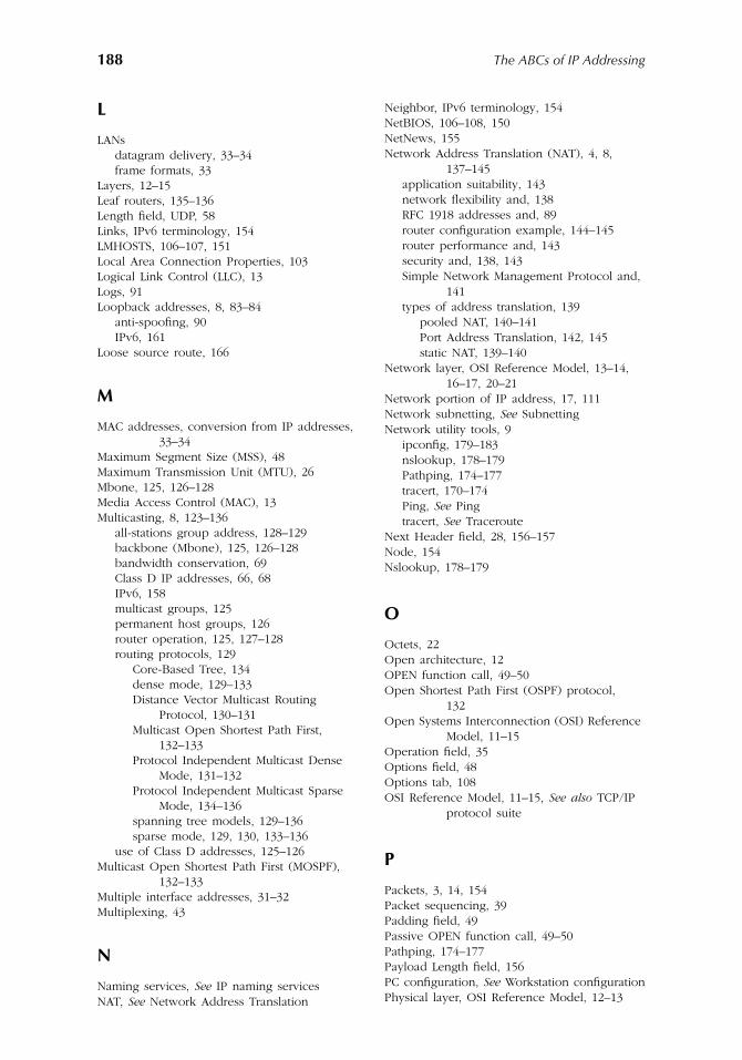
188
The ABCs of IP Addressing
L
LANsdatagram delivery, 33–34frame formats, 33
Layers, 12–15Leaf routers, 135–136Length field, UDP, 58Links, IPv6 terminology, 154LMHOSTS, 106–107, 151Local Area Connection Properties, 103Logical Link Control (LLC), 13Logs, 91Loopback addresses, 8, 83–84
anti-spoofing, 90IPv6, 161
Loose source route, 166
M
MAC addresses, conversion from IP addresses, 33–34
Maximum Segment Size (MSS), 48Maximum Transmission Unit (MTU), 26Mbone, 125, 126–128Media Access Control (MAC), 13Multicasting, 8, 123–136
all-stations group address, 128–129backbone (Mbone), 125, 126–128bandwidth conservation, 69Class D IP addresses, 66, 68IPv6, 158multicast groups, 125permanent host groups, 126router operation, 125, 127–128routing protocols, 129
Core-Based Tree, 134dense mode, 129–133Distance Vector Multicast Routing
Protocol, 130–131Multicast Open Shortest Path First,
132–133Protocol Independent Multicast Dense
Mode, 131–132Protocol Independent Multicast Sparse
Mode, 134–136spanning tree models, 129–136sparse mode, 129, 130, 133–136
use of Class D addresses, 125–126Multicast Open Shortest Path First (MOSPF),
132–133Multiple interface addresses, 31–32Multiplexing, 43
N
Naming services,
See
IP naming servicesNAT,
See
Network Address Translation
Neighbor, IPv6 terminology, 154NetBIOS, 106–108, 150NetNews, 155Network Address Translation (NAT), 4, 8,
137–145application suitability, 143network flexibility and, 138RFC 1918 addresses and, 89router configuration example, 144–145router performance and, 143security and, 138, 143Simple Network Management Protocol and,
141types of address translation, 139
pooled NAT, 140–141Port Address Translation, 142, 145static NAT, 139–140
Network layer, OSI Reference Model, 13–14, 16–17, 20–21
Network portion of IP address, 17, 111Network subnetting,
See
SubnettingNetwork utility tools, 9
ipconfig, 179–183nslookup, 178–179Pathping, 174–177tracert, 170–174Ping,
See
Pingtracert,
See
TracerouteNext Header field, 28, 156–157Node, 154Nslookup, 178–179
O
Octets, 22Open architecture, 12OPEN function call, 49–50Open Shortest Path First (OSPF) protocol,
132Open Systems Interconnection (OSI) Reference
Model, 11–15Operation field, 35Options field, 48Options tab, 108OSI Reference Model, 11–15,
See
also
TCP/IP protocol suite
P
Packets, 3, 14, 154Packet sequencing, 39Padding field, 49Passive OPEN function call, 49–50Pathping, 174–177Payload Length field, 156PC configuration,
See
Workstation configurationPhysical layer, OSI Reference Model, 12–13
AU1144_index_fm Page 188 Thursday, October 11, 2001 1:35 PM
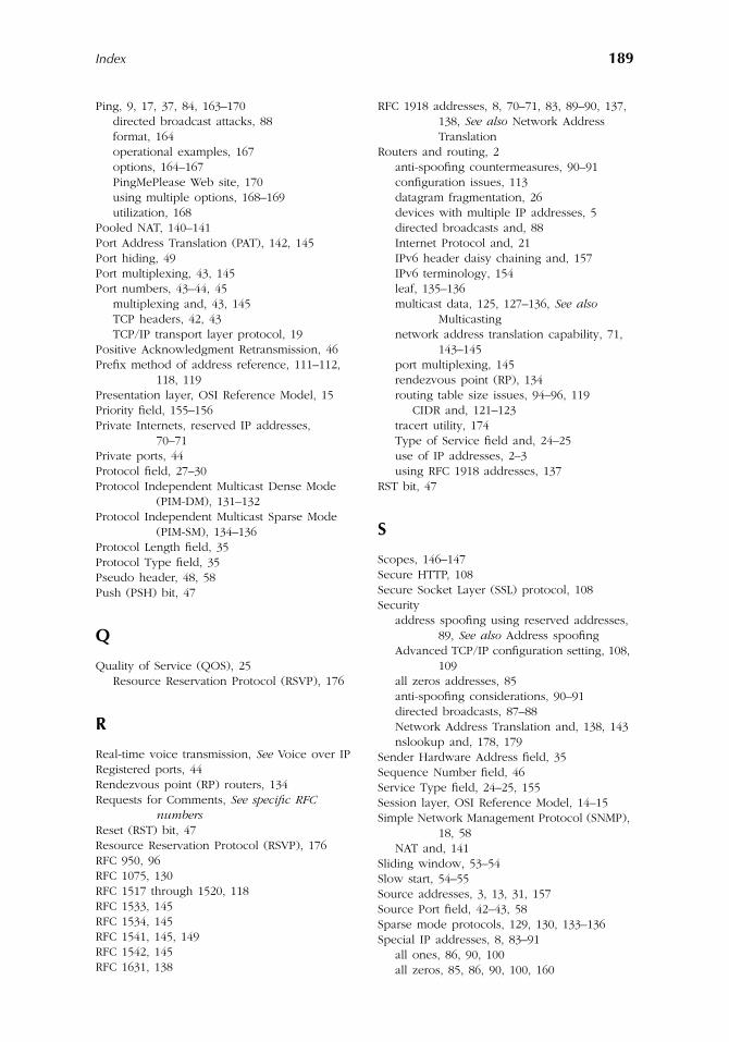
Index
189
Ping, 9, 17, 37, 84, 163–170directed broadcast attacks, 88format, 164operational examples, 167options, 164–167PingMePlease Web site, 170using multiple options, 168–169utilization, 168
Pooled NAT, 140–141Port Address Translation (PAT), 142, 145Port hiding, 49Port multiplexing, 43, 145Port numbers, 43–44, 45
multiplexing and, 43, 145TCP headers, 42, 43TCP/IP transport layer protocol, 19
Positive Acknowledgment Retransmission, 46Prefix method of address reference, 111–112,
118, 119Presentation layer, OSI Reference Model, 15Priority field, 155–156Private Internets, reserved IP addresses,
70–71Private ports, 44Protocol field, 27–30Protocol Independent Multicast Dense Mode
(PIM-DM), 131–132Protocol Independent Multicast Sparse Mode
(PIM-SM), 134–136Protocol Length field, 35Protocol Type field, 35Pseudo header, 48, 58Push (PSH) bit, 47
Q
Quality of Service (QOS), 25Resource Reservation Protocol (RSVP), 176
R
Real-time voice transmission,
See
Voice over IPRegistered ports, 44Rendezvous point (RP) routers, 134Requests for Comments,
See
specific
RFC
numbers
Reset (RST) bit, 47Resource Reservation Protocol (RSVP), 176RFC 950, 96RFC 1075, 130RFC 1517 through 1520, 118RFC 1533, 145RFC 1534, 145RFC 1541, 145, 149RFC 1542, 145RFC 1631, 138
RFC 1918 addresses, 8, 70–71, 83, 89–90, 137, 138,
See
also
Network Address Translation
Routers and routing, 2anti-spoofing countermeasures, 90–91configuration issues, 113datagram fragmentation, 26devices with multiple IP addresses, 5directed broadcasts and, 88Internet Protocol and, 21IPv6 header daisy chaining and, 157IPv6 terminology, 154leaf, 135–136multicast data, 125, 127–136,
See
also
Multicasting
network address translation capability, 71, 143–145
port multiplexing, 145rendezvous point (RP), 134routing table size issues, 94–96, 119
CIDR and, 121–123tracert utility, 174Type of Service field and, 24–25use of IP addresses, 2–3using RFC 1918 addresses, 137
RST bit, 47
S
Scopes, 146–147Secure HTTP, 108Secure Socket Layer (SSL) protocol, 108Security
address spoofing using reserved addresses, 89,
See
also
Address spoofingAdvanced TCP/IP configuration setting, 108,
109all zeros addresses, 85anti-spoofing considerations, 90–91directed broadcasts, 87–88Network Address Translation and, 138, 143nslookup and, 178, 179
Sender Hardware Address field, 35Sequence Number field, 46Service Type field, 24–25, 155Session layer, OSI Reference Model, 14–15Simple Network Management Protocol (SNMP),
18, 58NAT and, 141
Sliding window, 53–54Slow start, 54–55Source addresses, 3, 13, 31, 157Source Port field, 42–43, 58Sparse mode protocols, 129, 130, 133–136Special IP addresses, 8, 83–91
all ones, 86, 90, 100all zeros, 85, 86, 90, 100, 160
AU1144_index_fm Page 189 Thursday, October 11, 2001 1:35 PM
190
The ABCs of IP Addressing
anti-spoofing considerations, 90–91broadcast addresses, 86–89IPv6, 159–161loopback address, 83–84, 161RFC 1918 addresses, 8, 70–71, 83, 89–90, 137,
138subnet broadcast addresses, 88–89
Spoofing,
See
Address spoofingStatic NAT, 139–140Streams 2 Protocol, 23Strict source route, 166Subnet broadcast addresses, 88–89Subnet mask, 101–102, 115Subnetting, 8, 93–116
all-0s and all-1s, 100broadcast addresses, 113–114design considerations, 108
architecture, 112–114host considerations, 111number of subnets, 110–111
example, 98external view, 99–100host addresses, 100–101need for, 93–96prefix method of address reference, 111–112,
118process, 97–98RFC 950, 96subnet creation process, 98–99using host/subnet quantity tables, 115–116using third and fourth bytes, 115–116workstation or server configuration,
102–108Supernetting, 118Sychronization (SYN) bit, 47, 51
T
Target Hardware Address field, 35TCP,
See
Transmission Control ProtocolTCP/IP protocol suite, 7, 11–59,
See
also
IPv4 addressing; Transmission Control Protocol
address resolution, 16, 17, 20, 32–37,
See
also
Address Resolution Protocol
address space issues, 6application layer, 15, 19Boot Protocol (BOOTP), 145configuration settings, 102–108
DNS tab, 105IP Settings tab, 104Internet Protocol (TCP/IP) Properties, 103Options tab, 108WINS tab, 106–108
data flow, 19Internet Control Message Protocol (ICMP),
16, 17, 36–40
Internet Protocol, 20–21,
See
Internet Protocol
multiple network addresses, 31–32network layer, 16–17OSI Reference Model, 11–15
application layer, 15comparison, 16data flow, 15data link layer, 13network layer, 13–14physical layer, 12–13presentation layer, 15session layer, 14–15transport layer, 14
overview, 16transport layer, 17–19, 40,
See
also
Transmission Control Protocol; User Datagram Protocol
troubleshooting tools,
See
Network utility tools
Three-way handshake, 50–53Time to Live (TTL) field, 26, 157
Ping settings, 165–166tracert and, 172–173
Token-ringdatagram fragmentation, 25–2648-bit MAC addressing, 17frame format, 33Layer 2 protocol, 13
Total Length field, 25Traceroute (Tracert), 9, 27, 170–174
bottleneck determination, 174command options, 171–172operation, 172–173utilization, 173–174
Transmission Control Protocol (TCP), 17–18, 40, 42, 44–46
adaptive retransmission algorithm, 56connection function calls, 49–50error-free, connection-oriented protocol, 18,
42flow control, 48, 53–54headers, 42
Checksum, 48Code bits, 47Hlen, 47Options, 48packet sequencing, 42Padding, 49port numbers, 42–45Protocol field designation, 27pseudo header, 48Sequence and Acknowledgment Number
fields, 46Source and Destination port fields, 42–43Urgent Pointer, 48Window, 48, 54
Internet Telephony, 59
AU1144_index_fm Page 190 Thursday, October 11, 2001 1:35 PM
Index
191
Layer 4 connection-oriented protocol, 14Maximum Segment Size (MSS), 48multiplexing and demultiplexing, 43port hiding, 49port numbers, 19, 43, 44, 45session termination, 56sliding window, 53–54slow start and congestion control, 54–55TCP segments, 20three-way handshake, 50–53voice over IP and, 18–19
Transport layer, OSI Reference Model, 14Transport layer, TCP/IP protocol suite, 17–19,
40, 42,
See
also
Transmission Control Protocol; User Datagram Protocol
Troubleshooting tools,
See
Network utility toolsType of Service (TOS) field, 24–25, 155
Ping settings, 166
U
UDP,
See
User Datagram ProtocolUnicast addressing, IPv4, 123Unicast addressing, IPv6, 158Uniform Resource Locators (URLs), 4–6Urgent (URG) bit, 47Urgent Pointer field, 48URLs, 4–6User Datagram Protocol (UDP), 17–19, 40, 56–58
applications, 58–59connectionless Layer 4 protocol, 14datagrams, 20headers, 57–58multiplexing, 43port numbers, 43–44, 45Protocol field designation, 27use of port numbers, 19voice over IP and, 19
V
Version (Vers) field, 23, 154Voice over IP, 18–19
Service Type field and, 25testing signal latency using Ping, 168UDP applications, 58–59
W
Web casts, 125, 129Well-Known ports, 44, 45Wildcard mask, 91Window field, 48Windows Internet Naming Service (WINS),
150–152configuration settings, 106–108client operations, 151–152server operations, 151
Winipcfg, 179WINS,
See
Windows Internet Naming ServiceWINS tab, 106–108Workstation configuration, 81
Advanced TCP/IP Settings, 104–108DNS tab, 105IP Settings tab, 104Options tab, 108WINS tab, 106–108
DHCP settings, 150Internet Protocol (TCP/IP) Properties, 103for subnetting, 102–108troubleshooting utility (ipconfig), 179–183WINS, 151–152
X
X.25 protocol, 14
AU1144_index_fm Page 191 Thursday, October 11, 2001 1:35 PM

AU1144_index_fm Page 192 Thursday, October 11, 2001 1:35 PM