Embed Size (px)
Citation preview
DoE/Go/loo17-17
THE $2000ELECTRIC POWERTRAINOPTION-1 PROGRAM
Final Technical ReportJanuary, 1996 – February, 1999
NORTHROP GRUMMAN
Northrop Grumman CorporationElectronic Sensors and Systems Sector
Baltimore, Maryland 21203
Date Published: June, 1999
PREPARED FOR THE UNITED STATESDEPARTMENT OF ENERGY

DISCLAIMER
This report was prepared as an account of work sponsoredby an agency of the United States Government. Neitherthe United States Government nor any agency thereof, norany of their employees, make any warranty, express orimplied, or assumes any legal liability or responsibility forthe accuracy, completeness, or usefulness of anyinformation, apparatus, product, or process disclosed, orrepresents that its use would not infringe privately ownedrights. Reference herein to any specific commercialproduct, process, or service by trade name, trademark,manufacturer, or otherwise does not necessarily constituteor imply its endorsement, recommendation, or favoring bythe United States Government or any agency thereof. Theviews and opinions of authors expressed herein do notnecessarily state or reflect those of the United StatesGovernment or any agency thereof.
-.- --.-,- .. . —---. ---- -—.——.-—---- .,.

DISCLAIMER
Portions of this document may be illegiblein electronic image products. Images areproduced from the best available originaldocument.
NORTHROP GRUMWZ4AV The $2000 Electric PowertrainOption-1 Program
1
1.11.2
2
2.12.1.12.1.22.1.32.1.42.1.5
2.22.2.12.2.22.2.32,2.42.2.52.2.62.2.7
3
3.13.1.13.1.23.1.33.23.2.13.2.23.2.33.2.43.2.53.33.3.13.3.23.3.33.3.43.43.4.13.4.23.4.33.4.43.4.53.4.63.4.7
Table of Contents
INTRODUCTION ............................................................................................ 1-1
PROJECT OVERVIEW ..... ... ... ... ... ... ................... ... .. .................................... ... . 1-1
.suMMARY oF EFFoRTs .... ... ... ... ... ... ................... ... .. .............................. ... ....l.2
TECHNOLOGY DEVELOPMENT ... ... ... ................ .. ... ... ......... ...... ...... ... ...... .... 2-1
INTEGRATED POWER BLOCK .... ... ... .. ... ... ................ .. ... ... ... ... ... ... ... ... ... ... .... ...2.lintroduction ..................................................................................................2.lModule Construction ....................................................................................2.2Microelectronic Assembly ............................................................................2-5
Integrated Power Block Testing ...................................................................2.9Conclusion ...................................................................................................2-24
RESOLVERLESS CONTROL ................... ... .. ... ... .......... ... ... ... ... ...... ...... ............2.26Goal .............................................................................................................2-26
introduction ..................................................................................................2.26Evaluation of Different Approaches .............................................................2.26Resolverless Control Design ........................................................................2-27
No-Load Powertrain Testing ........................................................................2-27
Powertrain Testing with Back-to-Back Dynamometer Fixture ......................2-28Conclusion ...................................................................................................2-28
POWERTRAIN PRODUCT ENHANCEMENTS ..............................................3.l
DSP ENHANCEMENTS.... ...... ... ... ... .. ... ... ............. ... .. ... ......... ...... ... ... ... ... .... ...3.lIntroduction ..................................................................................................3-1
Results ........................................................................................................3.2Conclusion ...................................................................................................3-7
PRODUCTION VALIDATION AND ACCEPTANCE TEST .. ... .. .... ... ... ... ... ... ... ............ 3-8
Test Development Overview ........................................................................3-8Definition of the Use Environment ...............................................................3.8Design Test Objectives and Requirements ..................................................3.9Test Execution .............................................................................................3-1o
Test Results .................................................................................................3.ll
MANUFACTURING ACCEPTANCE TEST AND TEST EQUIPMENT....................... ....3-14Test Requirements ......................................................................................3.l4System and Sub-System Test Definition ......................................................3-14
Test Equipment Design Ovewiew ................................................................3.l5Test Equipment Design ...............................................................................3-16
MANUFACTURING PROCESS DEVELOPMENT ......... ... .. ... ... ... ... ... .... ... ...............3.l9Manufacturing Process Objectives ...............................................................3-19
Manufacturing Process Development Overview ...........................................3-19
Manufacturing Plan ......................................................................................3.l9Work Order and Work Instructions ..............................................................3-24
Process Analysis .........................................................................................3-25
Manufacturing Capability improvement ........................................................3.27Conclusion ...................................................................................................3-27
Table of Contents (Continued)
Final Report i Table Of Contents
NORTHROP GRUM-N The $2000 Electric PowertrainOption-1 Program
4. EXPANDED POWERTRAIN APPLICATION ..................................................4.l
4.14.1.14.1.24.1.34.1.44.24.2.14.2.24.2.34.2.44.34.3.14.3.24.3.3
INDUSTRIAL TURBO-GENERATOR SOFTWARE DEVELOPMENT AND TEST . . .. . .. . ...4-1
Goals and Objectives ...................................................................................4-1
Summary of Results ....................................................................................4.2Results ........................................................................................................4.2Conclusion ...................................................................................................4-15
HYBRID-ELECTRIC POWERTRAIN .................. .... ... ...... ... ... ... ... ... .. ... .......... ... ...4.l6Goals and Objectives ...................................................................................4.l6Results ........................................................................................................4-16
Hybrid-Electric Bus Generator .....................................................................4.l7Conclusion ...................................................................................................4.l9
ELECTRIC VEHICLE AUXILARY SUBSYSTEMS .................................. ......... ... ... ..........4-20
Goals and Objectives ...................................................................................4.2OResults ........................................................................................................4-20
Conclusion ...................................................................................................4.24
NORTHROP GRUM-N The $2000 Electric Powertrain
Figure 1.1-1Figure 1.2-1Figure 1.2-2Figure 1.2-3Figure 1.2-4Figure 2.1-1Figure 2.1-2Figure 2.1-3Figure 2.1-4Figure 2.1-5Figure 2.1-6Figure 2.1-7Figure 2.1-8Figure 2.1-9Figure 2.1-10Figure 2.1-11Figure 2.1-12Figure 2.1-13Figure 2.1-14Figure 2.1-15Figure 2.1-16Figure 2.1-17Figure 2.1-18Figure 2.1-19Figure 2.1-20Figure 2.1-21Figure 2.1-22Figure 2.1-23Figure 2.1-24Figure 2.1-25Figure 2.1-26Figure 2.1-27Figure 2.1-28Figure 2.2-1Figure 2.2-2Figure 3.1-1Figure 3.1-2Figure 3.1-3Figure 3.1-4Figure 3.1-5Figure 3.1-6Figure 3.1-7Figure 3.1-8Figure 3.2-1Figure 3.2-2Figure 3.2-3
Final Report
Option-1 Program
List of Figures
Production Powertrain Systems ...................................................................l.lIntegrated Power Block ................................................................................l.2Manufacturing Test-Set ...............................................................................l.3Industrial Turbine-Generator Power Electronics Unit ...................................1-4Initial Hybrid-Electric Powertrain Evaluation Platform ...................................l-4Integrated Power Block Reduces Cost and Size 2:1 ....................................2-1Major Parts of the Integrated Power Block ...................................................2.2IPB Laminated Structure ..............................................................................2.3Copper Sheet with Porous Copper Heat.sinks .............................................2.3Exploded View of the Integrated Power Block .............................................2-4Top View& Profile of a Single Pole .............................................................2.5Graphite Chip Mounting Soldering Fixture ...................................................2.6Carrier with Chips Mounted .........................................................................2.6X-Ray of Carrier Showing Voids Under Chips ..............................................2-6X-Ray of Carrier Showing Improved Process ...............................................2.6Chip Carrier with 20 mil Wire Bonds ............................................................2-7Integrated Bridge Showing Soldering and Wire Bonding .............................2-9Low Inductance IPB Reduces Over-Shoot By 67Yo......................................2-10Junction Temperature and Output Power Data ............................................2.l 1High Power DC Test Comparing Non-Flooded and Flooded Cooling ...........2-11Thermal Resistance With & Without Oil Flowing Over Wire Bonds ..............2-l 2Switch Temperatures at Various Power Levels ............................................2-13Temperature Comparison With and Without Oil on Chips ...........................2-14IGBT Voltage Waveform ..............................................................................2.l5IGBT Current Waveform ..............................................................................2.l58kHz Single Pole Output ..............................................................................2.l6Inframetrics’ SCI 000 ...................................................................................2-20IPB Showing IR Image Area ........................................................................2.2lLayout of Devices Within The IBP ...............................................................2-22Thermal image of Switch Under Test ..........................................................2.22IGBT Temperatures, Pole C, Upper Switch .................................................2.23IGBT Temperatures, Pole C, Lower Switch .................................................2.23IGBT Temperatures, Pole A, Lower Switch ..................................................2-24Production Resolver and Interface Hardware ..............................................2-26Voltage Feedback Algorithm ........................................................................2.27Code for Computing Sum-Of-Squares .........................................................3-2Optimized Code for Computing Sum-Of-Squares ........................................3-3Code for DCto AC Transform .....................................................................3.3Optimized Code for DC to AC Transform .....................................................3.4Code for Computing Rotor Speed ................................................................3-4Optimized Code for Computing Rotor Speed ...............................................3.5Exp-1 B Code Reaches 245 HP When Tested In 230 HP System ................3-5Version-3 Code Reaches 260 HP When Tested In 230 HP System ............3-6Test Flow Diagram .......................................................................................3-11Number of Failures vs. Stress Mechanism ...................................................3.l2Product Improvement Resulting From Testing Program ..............................3-13
List of Figures (Continued)
...111 Table Of Contents
.. ..... .. .--,- . ,,, , . ,“.,.=~., -. ,.. >,_ ,. C-- ,... m+... ., . ..+.. .,..,., ., ,.. “.. , .,. --
,,=—. -, .--. —— -.-—. . . .
NORTHROP GRUM-N The $2000 Electric Powertrain
Figure 3.2-4Figure 3.3-1Figure 3.3-2Figure 3.3-3Figure 3.3-4Figure 3.3-5Figure 3.4-1Figure 3.4-2Figure 3.4-3Figure 3.4-4Figure 3.4-5Figure 3.4-6Figure 4.1-1Figure 4.1-2Figure 4.1-3Figure 4.1-4Figure 4.1-5Figure 4.1-6Figure 4.1-7Figure 4.1-8Figure 4.1-9Figure 4.1-10Figure 4.2-1Figure 4.2-2Figure 4.2-3Figure 4.2-4Figure 4.3-1Figure 4.3-2Figure 4.3-3Figure 4.3-4Figure 4.3-5Figure 4.3-6
Option-1 Program
Design vs. Workmanship Related Issues as a Function of Test Phase .......3-13Automated Test Console .............................................................................3-17One of the Ten Styles of Test Console Adapter Pans ..................................3-17Test Fixture Power Supplies ........................................................................3-17First Generation Back to Back Fixture .........................................................3.l8Second Generation Back to Back Fixture With Cooling Cart .......................3-18SCU Process Flow Diagram ........................................................................3-20Floor Layout for Manufacturing Faclity .........................................................3-21Sub-Assembly Process Flow Diagram .........................................................3.22Sub-Assembly Installations Process Flow Diagram .....................................3-23Work Instruction for the EGW Pump Control Assembly ...............................3-24Graphic Aid for the EGW Pump Control Assembly ......................................3-25Alpha ITG ....................................................................................................4-1ITG Functional Block Diagram .....................................................................4.2ITG Control Block Diagram ..........................................................................4.3Communications Processor Block Diagram .................................................4.6TG Front Control Panel ................................................................................4-7ITG Remote-Host Main Menu ......................................................................4.8Interior of ITG Cabinet .................................................................................4-1oNGC Engineers and ITG unit at UniCom .....................................................4-11Multiple Unit Control Block Diagram ............................................................4.l4Artist Concept of Production ITG .................................................................4.l5Hybrid-Electric Bus Block Diagram ..............................................................4.l6Hybrid-Electric System Evaluation Set. Up ...................................................4.l7Hybrid-Electric Transit Bus with APU ...........................................................4-18GPS vs. Energy Data ...................................................................................4.l8Electric Bus with 230 HP Powetirain ............................................................4.2OElectric Bus Liquid Cooling System .............................................................4.2lElectric Bus Chassis Showing Installed Drive ..............................................4-22BESS Energy Conversion Electronics ..........................................................4.23BESS Battery Storage Rack ........................................................................4.23Charging Stations Integrated with BESS .....................................................4-23
Final Report iv Table Of Contents
,---r->,--,?F”m-,.,
—’.,. ,,, , ... . ...-...’” :. ,< ..?. . .. .. . ,. f., . ...+ .- ,w,>,.t,.~ ,.. ,:: 7-: -7... %-.;.?$5 . . ...>.. ,. # -a!. %..~is : -=?7?= --- “ --%W”- ‘“ ‘“
. .
NORTHROP GRUM-N The $2000 EIectric PowertrainOption-1 Program
List of Tables
Table 2.1-1Table 2.1-2Table 3.2-1Table 3.2-2Table 3.3-1Table 3.3-2Table 3.4-1Table 3.4-2Table 4.1-1
Chip Bounding Process ...............................................................................2-8lGBTTemperature Data ..............................................................................2.l8Tests Specified for Use in the Automotive Environment ..............................3-8Test Definition ..............................................................................................3-9Number of System Requirements ................................................................3.l4Manufacturing Acceptance Test Summary ..................................................3-15Process Failure & Effects Analysis ..............................................................3.26Examples of Manufacturing Capability Improvements .................................3-27ITG Communication protocol .......................................................................4-4
Fkal Report v Table Of Contents
. ,. ,.-.-.-mm,., . ... . .... ... -,.,.. e”.,............ ....... .7+,.., - . ., ....... . ...<+.. .. m, ,...,,., ,. , ... ,,T. — —7,—,—---- ----------
NORTHROP GRUM~N The $2000 Electric PowertrainOption-1 Program
1 INTRODUCTION
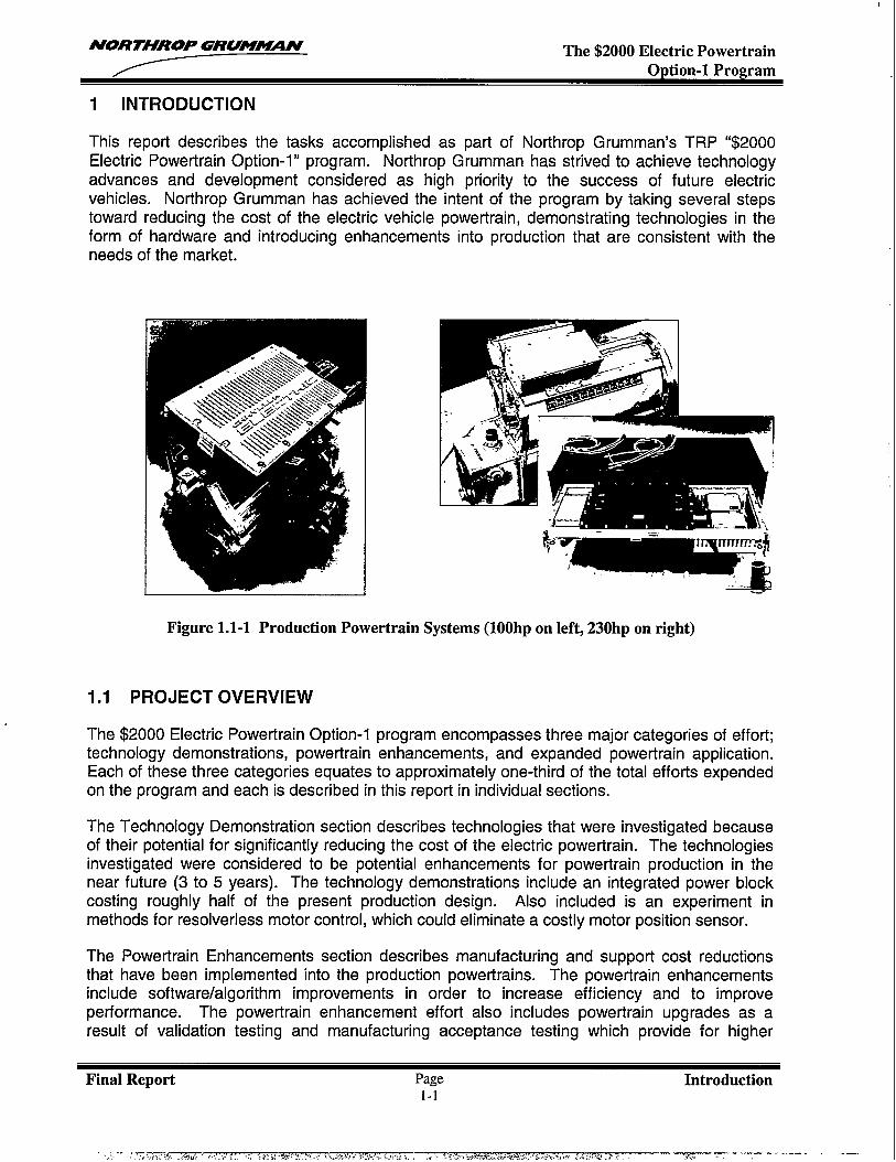
This report describes the tasks accomplished as part of Northrop Grumman’s TRP “$2000Electric Powertrain Option-1” program. Northrop Grumman has strived to achieve technologyadvances and development considered as high priority to the success of future electricvehicles. Northrop Grumman has achieved the intent of the program by taking several stepstoward reducing the cost of the electric vehicle powertrain, demonstrating technologies in theform of hardware and introducing enhancements into production that are consistent with theneeds of the market.
Figure 1.1-1 Production Powertrain Systems (100hp on left, 230hp on right)
1.1 PROJECT OVERVIEW
The $2000 Electric Powertrain Option-1technology demonstrations, powertrainEach of these three categories equates
program encompasses three major categories of effort;enhancements, and expanded powertrain application.to approximately one-third of the total efforts expended
on the program and each is described in this report in individual sections.
The Technology Demonstration section describes technologies that were investigated becauseof their potential for significantly reducing the cost of the electric powertrain. The technologiesinvestigated were considered to be potential enhancements for powertrain production in thenear future (3 to 5 years). The technology demonstrations include an integrated power blockcosting roughly half of the present production design. Also included is an experiment inmethods for resolverless motor control, which could eliminate a costly motor position sensor.
The Powertrain Enhancements section describes manufacturing and support cost reductionsthat have been implemented into the production powertrains. The powertrain enhancementsinclude software/algorithm improvements in order to increase efficiency and to improveperformance. The powertrain enhancement effort also includes powertrain upgrades as aresult of validation testing and manufacturing acceptance testing which provide for higher
Final Report Page Introduction1-1
.—.
NORTHROP GRUM~N The $2000 Electric PowertrainOption-1 Program
reliability and lower support cost. In addition, enhancements in producibility are described inthis section and include modular test equipment that supports every level of powertrainassembly, and manufacturing process enhancements for producing the powertrain product,increasing its production rate, and reducing hands-on labor time.
The Expanded Powertrain Application section describes enhancements to the powertrain or itsmajor subsystems to adapt it for use in applications other than the pure electric vehicle market.These other markets are targeted because of their need for a similar product and would have amajor impact on manufacturing quantity. One of the powertrain enhancements described in thissection is the adaptation of the electric powertrain to hybrid-electric vehicle platforms. Alsodescribed are changes to the powertrain’s motor controller software to adapt it for use inindustrial power generation applications.
1.2 SUMMARY OF EFFORTS
A summary of each of the major efforts undertaken as part of this TRP project is includedbelow. The efforts are presented in the order that each topic is described in the later sectionsof this report.
Integrated Power Block
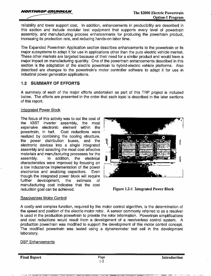
The focus of this activity was to cut the cost ofthe IGBT inverter assembly, the mostexpensive electronic element within thepowertrain, in half. Cost reductions wererealized by combining the cooling structure,the power distribution buses, and theelectronic devices into a single integratedassembly and selecting the most cost effectivematerials and manufacturing processes for theassembly. In addition, the electricalcharacteristics were improved by focusing ona low inductance implementation of the powerelectronics and snubbing capacitors. Eventhough the integrated power block will requirefurther development, the estimate ofmanufacturing cost indicates that the costreduction goal can be achieved.
Resolverless Motor Control
7I
n
Figure 1.2-1 Integrated Power Block
A costly and complex function, required by the motor control algorithm, is the determination ofthe speed and position of the electric motor rotor. A sensor commonly referred to as a resolveris used in the production powertrain to provide the rotor information. Powertrain simplificationsand cost reductions would result from a development of a resolverless control system. Aproduction powertrain was modified to support the development of this motor control concept.The modified powertrain was tested using a dynamometer test cell in the developmentlaboratory.
DSP Enhancements
Final Report Page Introduction1-2
- .... ., .-,- -....mv ,. . . . . . . . ,. .. >-... . . . . . ..-.—
----- ---.--—- --—- .-. .-
NORTHROP GRU!-N The $2000 Electric Powertrain
The purpose of this task was to enhance the performance of the Digital Signal Processing(DSP) software by reducing the processing timeline and incorporating new capability into thesystem for supporting a broader range of applications. The DSP code, the heart of thepowertrain controls, computes and outputs voltage control signals that drive the IGBTs,generating three-phase A/C currents and thereby applying the requested torque to the motorshaft. This lowest level of motor control was optimized for processing timeline, maintainability,and improved flexibility.
Production Validation and Acceptance Test
The production validation test program was developed to determine the stress mechanismswithin the powertrains and to implement enhancements to increase design margins of thesystems. The environment and stress mechanisms were defined and tests were determined.Test procedures were written and the powertrains were subjected to the defined tests. Testresults were compiled and as powertrain enhancements were implemented, the enhancementswere subjected to an applicable subset of the validation tests.
Manufacturing Acceptance Testand Test EauiPment
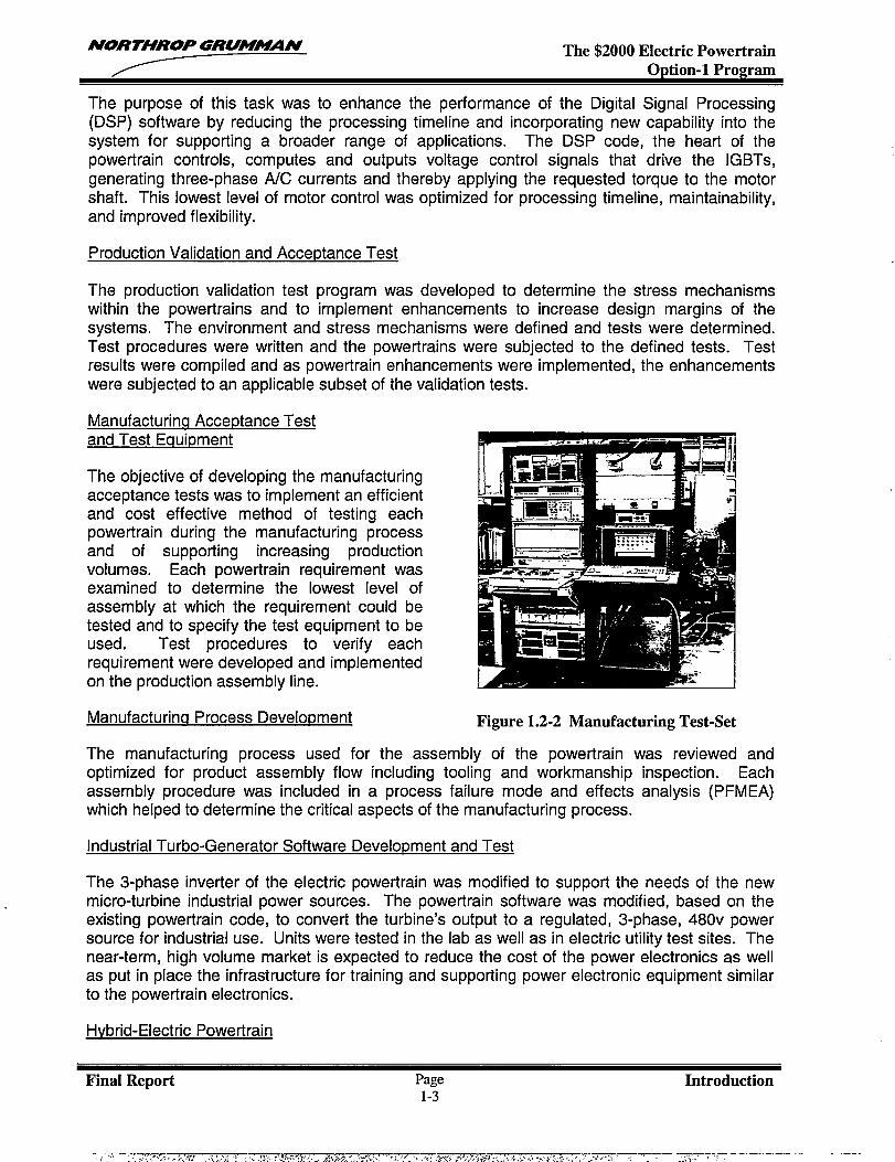
The objective of developing the manufacturingacceptance tests was to implement an efficientand cost effective method of testing eachpowertrain during the manufacturing processand of supporting increasing productionvolumes. Each powertrain requirement wasexamined to determine the lowest level ofassembly at which the requirement could betested and to specify the test equipment to beused. Test procedures to verify eachrequirement were developed and implementedon the production assembly line.
Manufacturincl Process Development Figure 1.2-2 Manufacturing Test-Set
The manufacturing process used for the assembly of the powertrain was reviewed andoptimized for product assembly flow including tooling and workmanship inspection. Eachassembly procedure was included in a process failure mode and effects analysis (PFMEA)which helped to determine the critical aspects of the manufacturing process.
Industrial Turbo-Generator Software Development and Test
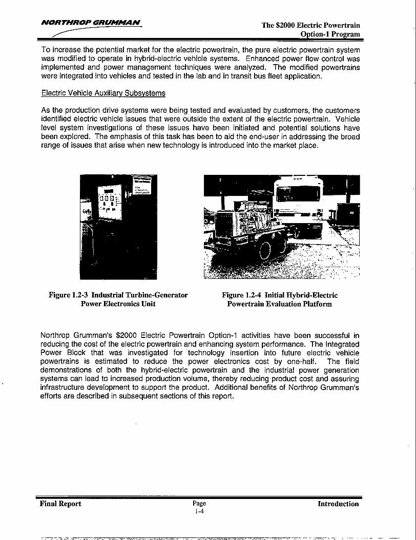
The 3-phase inverter of the electric powertrain was modified to support the needs of the newmicro-turbine industrial power sources. The powertrain software was modified, based on theexisting powertrain code, to convert the turbine’s output to a regulated, 3-phase, 480v powersource for industrial use. Units were tested in the lab as well as in electric utility test sites. Thenear-term, high volume market is expected to reduce the cost of the power electronics as wellas put in place the infrastructure for training and supporting power electronic equipment similarto the powertrain electronics.
Hvbrid-Electric Powertrain
Final Report Page Introduction1-3
NORTHROP GRUMMN The $2000 Electric PowertrainOption-1 Program
To increase the potential market for the electric powertrain, the pure electric powertrain systemwas modified to operate in hybrid-electric vehicle systems. Enhanced power flow control wasimplemented and power management techniques were analyzed. The modified powertrainswere integrated into vehicles and tested in the lab and in transit bus fleet application.
Electric Vehicle Auxiliarv Subsystems
As the production drive systems were being tested and evaluated by customers, the customersidentified electric vehicle issues that were outside the extent of the electric powertrain. Vehiclelevel system investigations of these issues have been initiated and potential solutions havebeen explored. The emphasis of this task has been to aid the end-user in addressing the broadrange of issues that arise when new technology is introduced into the market place.
Figure 1.2-3 Industrial Turbine-Generator Figure 1.2-4 Initial Hybrid-ElectricPower Electronics Unit Powertrain Evaluation Platform
Northrop Grumman’s $2000 Electric Powertrain Option-1 activities have been successful inreducing the cost of the electric powertrain and enhancing system performance. The IntegratedPower Block that was investigated for technology insertion into future electric vehiclepowertrains is estimated to reduce the power electronics cost by one-half. The fielddemonstrations of both the hybrid-electric powertrain and the industrial power generationsystems can lead to increased production volume, thereby reducing product cost and assuringinfrastructure development to support the product. Additional benefits of Northrop Grumman’sefforts are described in subsequent sections of this report.
Final Report Page Introduction1-4
.,..—.-=, .,,-,.,,.. ....,,, ,C.,..,-.,,,,.,<,,,~,,,,,,.+, .\,..+,+ ,-,,~. ..,-—,_ ~—. ....=,-.---..—. ..... .. .—.
NORTHROP GRUM~ff The $2000 Electric PowertrainOption-1 Program
2 TECHNOLOGY DEVELOPMENT
The technology development section describes technologies that were investigated because oftheir potential of significantly reducing the cost of the electric powertrain. The technologiesinvestigated were considered to be potential enhancements for near future (3 to 5 years)production powertrains. The technology demonstrations include an integrated power blockcosting roughly half of the present production design. Aiso included is an experiment in
methods for resolverless motor control, which could eliminate a costly motor position sensor.
2.1 INTEGRATED POWER BLOCK DEVELOPMENT
2.1.1 Introduction
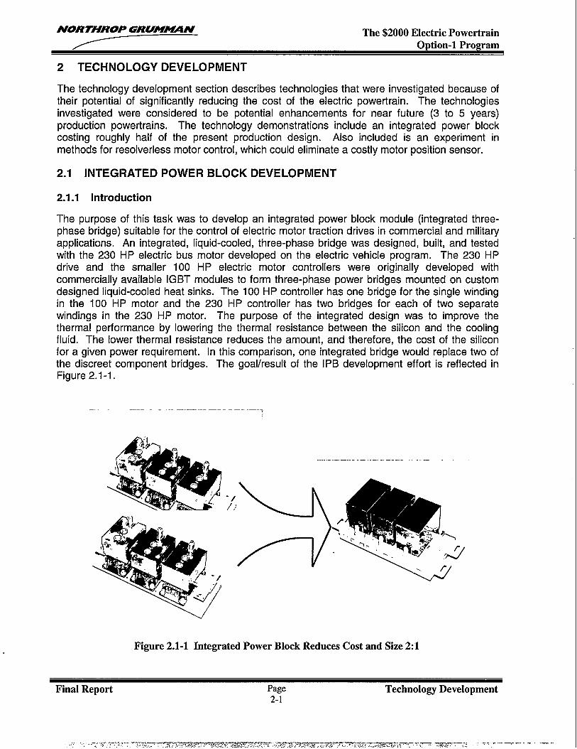
The purpose of this task was to develop an integrated power block module (integrated three-phase bridge) suitable for the control of electric motor traction drives in commercial and militaryapplications. An integrated, liquid-cooled, three-phase bridge was designed, built, and testedwith the 230 HP electric bus motor developed on the electric vehicle program. The 230 HPdrive and the smaller 100 HP electric motor controllers were originally developed withcommercially available IGBT modules to form three-phase power bridges mounted on customdesigned liquid-cooled heat sinks. The 100 HP controller has one bridge for the single windingin the 100 HP motor and the 230 HP controller has two bridges for each of two separatewindings in the 230 HP motor. The purpose of the integrated design was to improve thethermal performance by lowering the thermal resistance between the silicon and the coolingfluid. The lower thermal resistance reduces the amount, and therefore, the cost of the siliconfor a given power requirement. In this comparison, one integrated bridge would replace two ofthe discreet component bridges. The goal/result of the IPB development effort is reflected inFigure 2.1-1.
—.- ————-. ————.. . . .——
‘~?e.’-.r
Figure 2.1-1 Integrated Power Block Reduces Cost and Size 2:1
Final Report Page Technology Development2-1
NORTHROP GRU!M~N The $2000 Electric PowertrainOption-1 Program
The integrated power block was tested in two ways. One way was with liquid coolant flowingthrough copper porous metal heat exchangers located directly below each die. In thisconfiguration, the integrated power block could dissipate 2.08 times as much heat as thestandard discreet bridge for the same silicon and coolant temperatures. The other testconfiguration was to allow the liquid coolant to flow over the top surface of the chips and wirebonds as well as through the porous heat sink. In this configuration, the power block coulddissipate 2.97 times as much heat as the standard discreet module with the same silicon andcoolant temperatures. One solid state switch survived a DC current of 1000 Amps whiledissipating over 5,000 Watts per square inch in this configuration. The normalized thermalresistances of the discreet bridge and the two configurations of the integrated power block are:0.115, 0.055, and 0.038 (degrees C * square inch)/Watt, where the square inch figure refers tothe silicon chip area under the chip but not including the area of the top side.
2.1.2 Module Construction
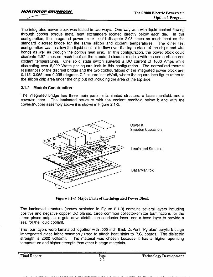
The integrated bridge has three main parts, a laminated structure, a base manifold, and acover/snubber. The laminated structure with the coolant manifold below it and with thecover/snubber assembly above it is shown in Figure 2.1-2.
Cover &Snubber Capacitors
Laminated Structure
Base/Manifold
Figure 2.1-2 Major Parts of the Integrated Power Block
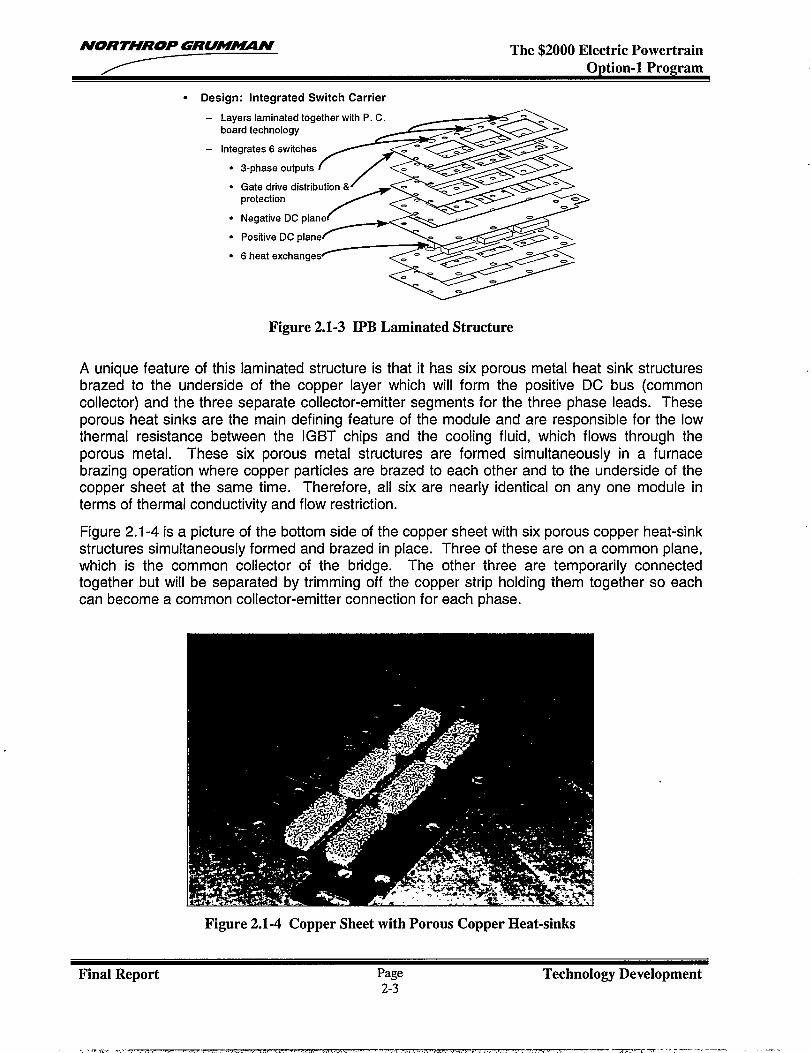
The laminated structure (shown exploded in Figure 2.1-3) contains several layers includingpositive and negative copper DC planes, three common collector-emitter terminations for thethree phase outputs, a gate drive distribution conductor layer, and a base layer to provide aseal for the liquid coolant.
The four layers were laminated together with .005 inch thick DuPont “Pyralux” acrylic b-stageimpregnated glass fabric commonly used to attach heat sinks to P.C. boards. The dielectricstrength is 2000 volts/roil. This material was chosen because it has a higher operatingtemperature and higher strength than other b-stage materials.
Final Report Page Technolo~ Development2-2
. ,- .-,.-,-r.-.-, z,--,. ~e. . . , . ,. . . . . .,, ,!. ..,- . .. . .-?. . . . . . . . . . .“., . ,. -— ----. . . . . . .
NORTHROP GRUMMN The $2000 Electric PowertrainOption-1 Program
● Design: Integrated Switch Carrier
- Layers laminated together with P. C.board technology
s-pha.eo.tp.lsfi--~- Integrates 6 switches
%
Gate drive distribution &
/
.
protection
Negative DC plane
Positive DC plane F:+
6 heat exchanges
●
●
●
●
●
A unique feature of this
Figure 2.1-3 IPB Laminated Structure
laminated structure is that it has six porous metal heat sink structuresbrazed to the underside of the copper layer which will form the positive DC bus (commoncollector) and the three separate collector-emitter segments for the three phase leads. Theseporous heat sinks are the main defining feature of the module and are responsible for the lowthermal resistance between the IGBT chips and the cooling fluid, which flows through theporous metal. These six porous metal structures are formed simultaneously in a furnacebrazing operation where copper particles are brazed to each other and to the underside of thecopper sheet at the same time. Therefore, all six are nearly identical on any one module interms of thermal conductivity and flow restriction.
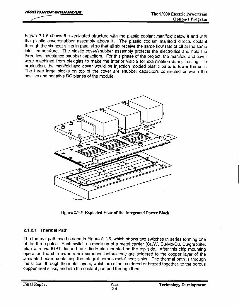
Figure 2.1-4 is a picture of the bottom side of the copper sheet with six porous copper heat-sinkstructures simultaneously formed and brazed in place. Three of these are on a common plane,which is the common collector of the bridge. The other three are temporarily connectedtogether but will be separated by trimming off the copper strip holding them together so eachcan become a common collector-emitter connection for each phase.
Figure 2.1-4 Copper Sheet with Porous Copper Heat-sinks
Final Report Page Technolo~ Development2-3
. . “ .-, .,- ..-— .— m .-,. - ------ .-, .— ___
NORTHROP GRUM~N The $2000 Electric PowertrainOption-1 Program
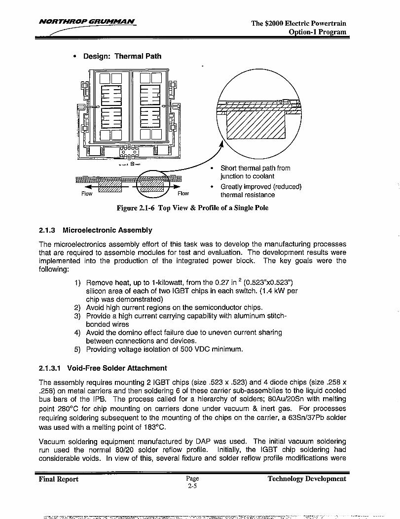
Figure 2.1-5 shows the laminated structure with the plastic coolant manifold below it and withthe plastic cover/snubber assembly above it. The plastic coolant manifold directs coolantthrough the six heat-sinks in parallel so that all six receive the same flow rate of oil at the sameinlet temperature. The plastic cover/snubber assembly protects the electronics and hold thethree low inductance snubber capacitors. For this phase of the project, the manifold and coverwere machined from plexiglas to make the interior visible for examination during testing. Inproduction, the manifold and cover would be injection molded plastic parts to lower the cost.The three large blocks on top of the cover are snubber capacitors connected between thepositive and negative DC planes of the module.
Figure 2.1-5 Exploded View of the Integrated Power Block
2.1.2.1 Thermal Path
The thermal path can be seen in Figure 2.1-6, which shows two switches in series forming oneof the three poles. Each switch us made up of a metal carrier (Cu/W, Cu/Mo/Cu, Cu/graphite,etc.) with two IGBT die and four diode die mounted on the top side. After this chip mountingoperation the chip carriers are screened before they are soldered to the copper layer of thelaminated board containing the integral porous metal heat sinks. The thermal path is throughthe silicon, through the metal layers, which are either soldered or brazed together, to the porouscopper heat sinks, and into the coolant pumped through them.
Final Report Page Technology Development2-4
NORTHROP GRUMUN The $2000 Electric PowertrainOption-1 Program
● Design: Thermal Path
● Short thermal path fromjunction to coolant
● Greatly improved (reduced)thermal resistance
Figure 2.1-6 Top View & Profile of a Single Pole
2.1.3 Microelectronic Assembly
The microelectronics assembly effort of this task was to develop the manufacturing processesthat are reauired to assemble modules for test and evaluation. The develo~ment results wereimplementedfollowing:
1)
2)3)
4)
5)
into the production of the integrated power block. The key goals were the
Remove heat, up to 1-kilowatt, from the 0.27 in 2 (0.523x0.523)silicon area of each of two IGBT chips in each switch. (1.4 kW perchip was demonstrated)Avoid high current regions on the semiconductor chips.Provide a high current carrying capability with aluminum stitch-bonded wiresAvoid the domino effect failure due to uneven current sharingbetween connections and devices.Providing voltage isolation
2.1.3.1 Void-Free Solder Attachment
The assembly requires mounting 2 IGBT
of 500 VDC minimum.
chips (size .523 x .523) and 4 diode chips (size .258 x.258) on metal carriers and then soldering 6 of these carrier sub-assemblies to the liquid cooledbus bars of the IPB. The process called for a hierarchy of solders; 80Au/20Sn with melting
point 280°C for chip mounting on carriers done under vacuum & inert gas. For processesrequiring soldering subsequent to the mounting of the chips on the carrier, a 63Sn/37Pb solder
was used with a melting point of 183°C.
Vacuum soldering equipment manufactured by DAP was used. The initial vacuum solderingrun used the normal 80/20 solder reflow profile. Initially, the IGBT chip soldering hadconsiderable voids. In view of this, several fixture and solder reflow profile modifications were
Final Report Page Technology Development2-5

NORTHROP GRUM4WIN The $2000 Electric PowertrainOption-1 Program
tested to achieve void free soldering. The following vacuum soldering process enhancementswere implemented for a successful solder reflow:
● Soldering fixture using graphite material, ● Use ultrasonic and plasma cleaningshown in Figure 2.1-7. procedures.
● Increase inert gas pressure in chamber. ● Add soak time preceding the solder reflow.● Add access hole to the fixture to direct gas
to the chips.● Use additional weight on each IGBT chip.
.. ..— — r--——--— ------
-.. ..*---- ?s..-.-.... .. . #. .. .. .. .
0 ::;: J-- : j–-.. .
e :::: k-..-...-....* >... ...-.... .... . ;[ ““~ :];... ...-. $. . . ...-.
0 y::
m. . . . -,. . . .-...---- p[ J ;~~*...---- .. .. .. .... .. .... . 4$—.-.. .
e -w................:::*. ..-...-.........a. . . .. . . .. . . .-.. .. . . ...*.. . . .-...----..*.. . . .. . . .---- 0. . . .:::: Q. . . ...-.
. . ::::
ditiiigik,
— . .. . . . J
Figure 2.1-7 Graphite Chip Mounting Soldering Fixture
Figure 2.1-8 is an optical photograph of the chips mounted to a metal carrier. Figure 2.1-9 is anX-ray of the carrier assembly showing voids in the gold-tin solder using a standard solder reflowprocess. Figure 2.1-10 is an X-ray which shows the greatly reduced voids after optimizing thesolder reflow process.
——.. .——. - ..
iltlmmmFigure 2.1-8 Carrier with Figure 2.1-9 X-Ray of Figure 2.1-10 X-Ray of
Chips Mounted Carrier Showing Voids Carrier Showing ImprovedUnder Chips Process
Final Report Page Technology Development2-6
NORTHROP GRUM-N The $2000 Electric PowertrainOption-1 Program
2.1.3.2 Solder Attachment of Chip Carriers to Bus Bars
The eutectic 63 /37 tin/lead solder alloy was used for attaching the chip carriers to the copperbus bars. An experiment was performed in a glove box to determine the solder temperatureprofile required for use in the Watkins-Johnson’s belt furnace. Two critical requirements of thisprocess were to obtain high voltage isolation (500 VDC) and to produce void-free solder jointsbetween the carrier and heat sink to maintain low thermal resistance. The spacing between thecarriers and the edges of the DC planes had to be maintained at 25 roils minimum to meet thehigh voltage isolation and a minimum of 80% solder coverage had to be obtained for eachcarrier mounted to the bus bars of the iPB.
2.1.3.3 Wire Bonding Development
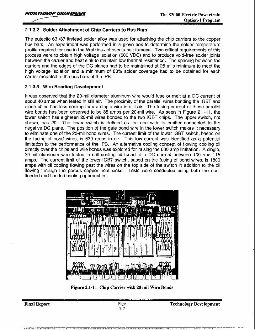
It was observed that the 20-mii diameter aluminum wire would fuse or melt at a DC current ofabout 40 amps when tested in still air. The proximity of the parallel wires bonding the IGBT anddiode chips has less cooling than a single wire in still air. The fusing current of these parallelwire bonds has been observed to be 35 amps per 20-mil wire. As seen in Figure 2.1-11, thelower switch has eighteen 20-mil wires bonded to the two IGBT chips. The upper switch, notshown, has 20. The lower switch is defined as the one with its emitter connected to thenegative DC plane. The position of the gate bond wire in the lower switch makes it necessaryto eliminate one of the 20-mil bond wires. The current limit of the lower IGBT switch, based onthe fusing of bond wires, is 630 amps in air. This low current was identified as a potentiallimitation to the performance of the IPB. An alternative cooling concept of flowing cooling oildirectly over the chips and wire bonds was explored for raising the 630 amp limitation. A single,20-mil aluminum wire tested in still cooling oil fused at a DC current between 100 and 115amps. The current limit of the lower IGBT switch, based on the fusing of bond wires, is 1800amps with oil cooling flowing past the wires on the top side of the switch in addition to the oilflowing through the porous copper heat sinks. Tests were conducted using both the non-flooded and flooded cooling approaches.
Figure 2.1-11 Chip Carrier with 20 mil Wire Bonds
Final Report Page Technolo~ Development2-7
:; C%z ?T.:’z?m. .-.~-- .,.- —--
NORTHROP GRUM-N The $2000 Electric PowertrainOption-1 Program
The 0.020 inch diameter aluminum wire bond process for the IGBT and diode chips had to bedeveloped. The development was done using both a K&S manual ultrasonic bonder and anOrthodyne 360 automatic heavy ultrasonic bonder. A critical aspect of bonding the 20-milaluminum wire was the selection of bonding parameters. They must allow each wire to bebonded on a thin IGBT chip without electrically or mechanically damaging the device. It wasuncovered that 0.020” aluminum wire was not used in industry and user guidelines of the wirebond process had not been established. During the first development phase, 20% of the IGBTdevices failed electrical test largely due to damage incurred during the wire bonding process. ADesign of Experiment statistical process control step, was incorporated to establish theoptimum bonding parameters
Design Of Experiment (DOE) was used to improve yield or optimize a manufacturing process.The experiment used the Orthodyne Model 360C, an automatic large wire bonder. A centralcomposite design of experiment was chosen with 3 different factors on two types of wire, SPM.9999 Al and SPM .99999 Al. The parameters tested were the following:
1) force - gram force exerted by the tool onto the work surface.2) time - duration of ultrasonic energy output to the transducer.3) power - level of ultrasonic energy output to the transducer.
The bonding process was applied on experiment coupons, which were identical to IGBT chipsattached to metal carriers used for the IPB. Prior to wire bonding, the IGBT die were examinedfor damage, such as cracks and scratches, and then tested electrically. After wire bounding,sample coupons that passed the visual and electrical test were subjected to high current tests.Each IGBT chip was subjected to a high current DC test, and high current AC test.
After all testing was completed, sample coupons that passed the visual and electrical test weredestructively tested. Some were subjected to tensile pull tested before and after the heat-age
test at 300”C for 1 hour. Others were subjected to higher and higher current levels until failureoccurred.
2.1.3.4 Microelectronics Final Assembly Process
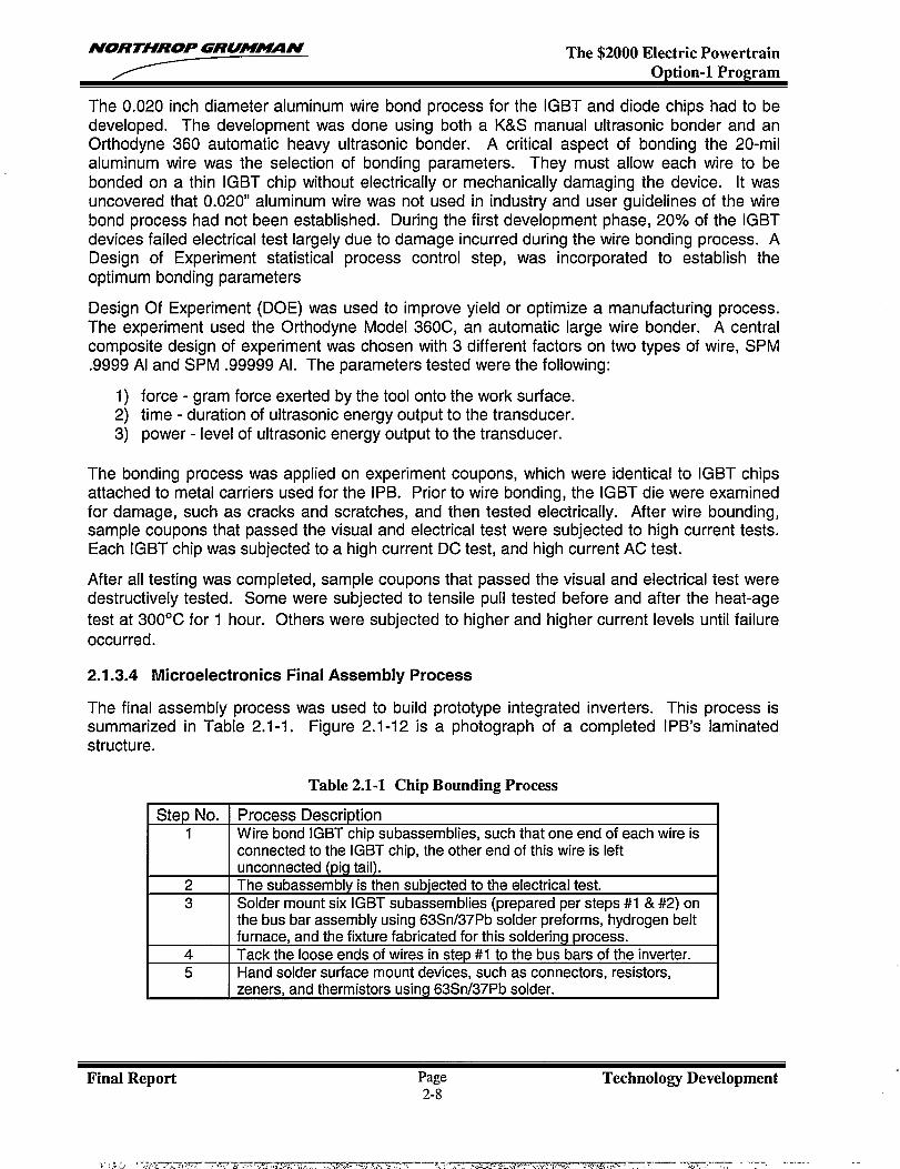
The final assembly process was used to build prototype integrated inverters.summarized in Table 2.1-1. Figure 2.1-12 is a photograph of a completedstructure.
Table 2.1-1 Chip Bounding Process
This process isIPB’s laminated
Step No. I Process Description1 I Wire bond IGBT chip subassemblies, such that one end of each wire is
connected to the IGBT chip, the other end of this wire is leftunconnected (pig tail).
2 The subassembly is then subjected to the electrical test.3 Solder mount six IGBT subassemblies (mepared ~er sterxsi#1 a #2) on
the bus bar assembly using 63Sn/37Pb’solder preforms, ”hydrogen beltfurnace, and the fixture fabricated for this soldering process.
4 Tack the loose ends of wires in step W to the bus bars of the inverter.5 Hand solder surface mount devices, such as connectors, resistors,
zeners, and thermistors using 63Sn/37Pb solder.
Final Report Page Technology Development2-8
;r,: ,., ,.,-J”.,-=~ -,=, ,—— .—, ----
NORTHROP GRUM~N The $2000 Electric PowertrainOption-1 Program
7,..i.“
‘*
--lFigure 2.1-12 Integrated Bridge Showing Soldering and Wire Bonding
2.1.4 Integrated Power Block Testing
2.1.4.1 Switch Test
Each switch of the fully assembled inverter was subjected to an electrical test at the maximumcurrent and voltage rating of the IPB. This required high current and voltage measurementequipment, an IGBT custom designed driver circuit, and an inductive load. The electrical testpower level was initially 450-ampere DC at 350 VDC. As electrical testing continued, the testcurrent eventually increased to a final (one-time) test of 1000 amps (DC conduction loss at lowvoltage). To support the original design intent, the goal of the manufacturing process
development was to obtain a minimum power density 1,300 watt/ in2, which is about double theexisting state-of-the-art value (750 watt / in2). The 1000 amp test mentioned above, was over5,000 Watts per square inch.
2.1.4.2 DC Voltage Overshoot Test
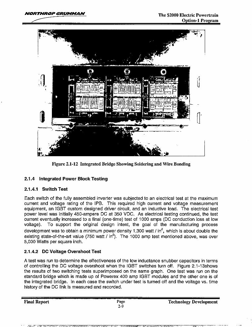
A test was run to determine the effectiveness of the low inductance snubber capacitors in termsof controlling the DC voltage overshoot when the IGBT switches turn off. Figure 2.1-13showsthe results of two switching tests superimposed on the same graph. One test was run on thestandard bridge which is made up of Powerex 400 amp IGBT modules and the other one is ofthe integrated bridge. [n each case the switch under test is turned off and the voltage vs. timehistory of the DC link is measured and recorded.
Final Report Page Technology Development2-9
- :,q.::-,,~,,,, .,lr— --------- ----- .-
NORTHROP GRUM~N The $2000 Electric PowertrainOption-1 Program
Switching 400 volts, 400 amps
500
1 ‘4””
.- .$...- ,~ .*T
400?
‘CE !300 ., 4~200 :“ “: ““’/” “ “’”’;
100 ,“’’”!”’ ””i’”’’i’””i.;. .
t’. J+ ,~
:.. .10 : -;--y-y-’,.. . . . I
Discrete BridgeUsing Powerex1 GBT CM400DY -12H
IPB UsingInternational Rectifier1RG4CC81 VB
r::: :1:: .’”1....... ...... . . .
L. .,.... . . . . . . . . . . . . . ...+..... . . . . . . . ..4. .. . . ~+ l+: loons” ;,.. .. . . + ;,. ., j
Figure 2.1-13 Low Inductance IPB Reduces Over-Shoot By 67%
In both cases, the DC link voltage was 360 volts. [n the case of the standard bridge, the DCvoltage came up to about 480 volts before settling back to 360 volts. The integrated bridgeswitch came up to about 400 volts before settling back to 360 volts. The overshoot for thestandard bridge was about 120 volts and for the integrated bridge, about 40 volts. Theinductance of the improved capacitor was measured at about 5 nano-Henrys compared toabout 50 nano-Henrys for the standard capacitor.
2.1.4.3 DC Thermal Dissipation Tests
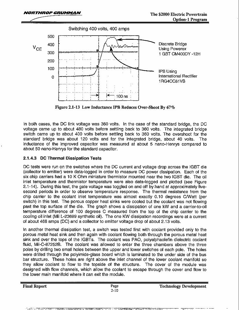
DC tests were run on the switches where the DC current and voltage drop across the IGBT die(collector to emitter) were data-logged in order to measure DC power dissipation. Each of thesix chip carriers had a 10 K Ohm miniature thermistor mounted near the two IGBT die. The oilinlet temperature and thermistor temperature were also data-logged and plotted (see Figure2.1-1 4). During this test, the gate voltage was toggled on and off by hand at approximately five-second periods in order to observe temperature response. The thermal resistance from thechip carrier to the coolant inlet temperature was almost exactly 0.10 degrees C/Watt (perswitch) in this test. The porous copper heat sinks were cooled but the coolant was not flowingpast the top surface of the die. The graph shows a dissipation of one kW and a carrier-to-oiltemperature difference of 100 degrees C measured from the top of the chip carrier to thecooling oil inlet (Mil L-23699 synthetic oil). The one KW dissipation recordings were at a currentof about 468 amps (DC) and a collector to emitter voltage drop of about 2.13 volts.
In another thermal dissipation test, a switch was tested first with coolant provided only to theporous metal heat sink and then again with coolant flowing both through the porous metal heatsink and over the tops of the IGBTs. The coolant was PAO, polyalphaolefin dielectric coolantfluid, Mil-C-87252B. The coolant was allowed to enter the three chambers above the threepoles by drilling two small holes between the upper and lower switches of each pole. The holeswere drilled through the polyimide-glass board which is laminated to the under side of the busbar structure. These holes are right above the inlet channel of the lower coolant manifold sothey allow coolant to flow to the topside of the structure. The cover of the module wasdesigned with flow channels, which allow the coolant to escape through the cover and flow tothe lower main manifold where it can exit the module.
Final Report Page Technology Development2-1o
-.,~,mr..!,=s 3 , .,,7 -,.. r,.*,,, i,,>.&, [.x.,,.,<., .: .. ... .%.7 ;.,, !... ,. . . .. -q-. ..,, , . . . . . . . . ‘.... s. . ‘ \. -t~s...f...--. ,, - , ./.. . . ——-’ --- --—
NORTHROP GRUMMN The $2000 Electric PowertrainOption-1 Program
1.2
1
0.8
0.6
0.4
0.2
0mod-a)<: mm :N
Figure 2.1-14
cNcood-cocNCDCD comfml ii k ha
SECONDS
— DELTATEMP/100
.... .......... Kw
JunctionTemperature and Output Power Data
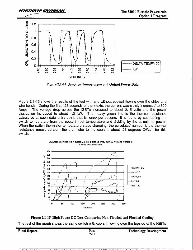
Figure 2.1-15 shows the results of the test with and without coolant flowing over the chips andwire bonds. During the first 125 seconds of the x-axis, the current was slowly increased to 600Amps. The voltage drop across the IGBTs increased to about 2.15 volts and the powerdissipation increased to about 1.3 kW. The heavy green line is the thermal resistancecalculated at each data entry point, that is, once per second. It is found by subtracting theswitch temperature from the coolant inlet temperature and dividing by the calculated power.When the switch thermistor temperature stops changing, the calculated number is the thermalresistance measured from the thermistor to the coolant, about .08 degrees C/Watt for thisswitch.
Cu/Gfaphite switch temp, currant, &dissipation vs time, 8/27/98 with and withoti oilflowhg over wrcbonds
El—SWITCH B2
—amps/10
c/w”looo
— kw”100
—Vca”loo
0 50 100 150 200 291 300 350
seconds
Figure 2.1-15 High Power DC Test Comparing Non-Flooded and F1ooded Cooling
The rest of the graph shows the same switch with coolant flowing over the topside of the IGBTs
Final Report Page Technology Development2-11
.—,.,p,--%,-m .—~ ... . -. . . . . .
NORTHROP GRUM-N The $2000 Electric PowertrainOption-1 Program
as well as through the porous heat sinks. In this case the current was slowly increased to 1000amps, the voltage drop increased to 2.8 volts, the dissipation increased to 2.8 kW. The heavygreen line representing the thermal resistance decreases from about .07 degrees C/Watt toabout .05 degrees C/Watt at full power. The reason for this noticeable decrease is probablydue to the decreased viscosity of the coolant oil. The film coefficient, and therefore the heattransfer, is higher with lower viscosity. The power dissipation in this DC test was over 5000Watts per square inch of silicon (787-watts/square cm). The temperature was too high forsilicon (160 C) but not too high for silicon carbide.
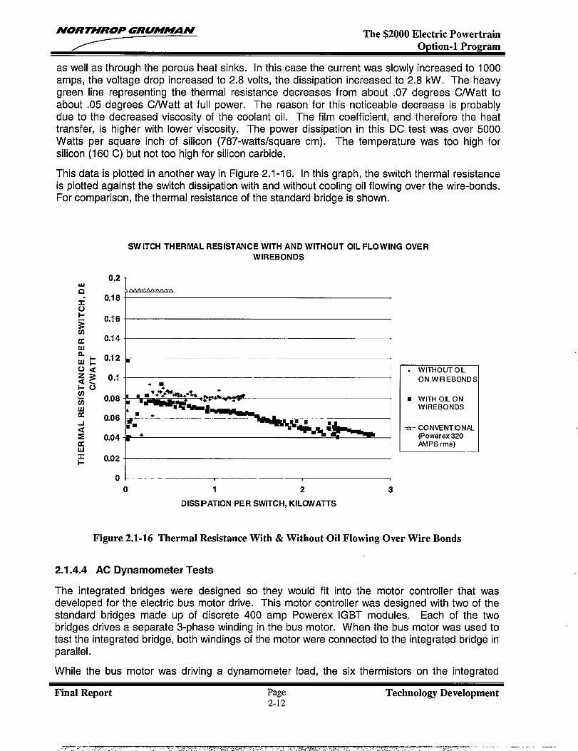
This data is plotted in another way in Figure 2.1-16. In this graph, the switch thermal resistanceis plotted against the switch dissipation with and without cooling oil flowing over the wire-bonds.For comparison, the thermal resistance of the standard bridge is shown.
SWITCH THERMAL RESISTANCE WITH AND WITHOUT OIL FLOWING OVERWIREBONDS
a
-1
0.2
0.18
0.16
0.14
0.12
0.1
0.08
0.06
0.04
0.02
0
I.m
● WITHOUTOL
ON WREBOND:
■ WITH OLONWIRE BONDS
-a– CO NVENTDNAL(Powerex 320AMPS rms)
o 1 2 3
DISSIPATION PER SWITCH, KILOiVATTS
Figure 2.1-16 Thermal Resistance With & Without Oil F1owing Over Wire Bonds
2.1.4.4 AC Dynamometer Tests
The integrated bridges were designed so they would fit into the motor controller that wasdeveloped for the electric bus motor drive. This motor controller was designed with two of thestandard bridges made up of discrete 400 amp Powerex IGBT modules. Each of the twobridges drives a separate 3-phase winding in the bus motor. When the bus motor was used totest the integrated bridge, both windings of the motor were connected to the integrated bridge inparallel.
While the bus motor was driving a dynamometer load, the six thermistors on the integrated
Final Report Page Technology Development2-12
NORTHROP GRUMHYiN The $2000 Electric PowertrainOption-1 Program
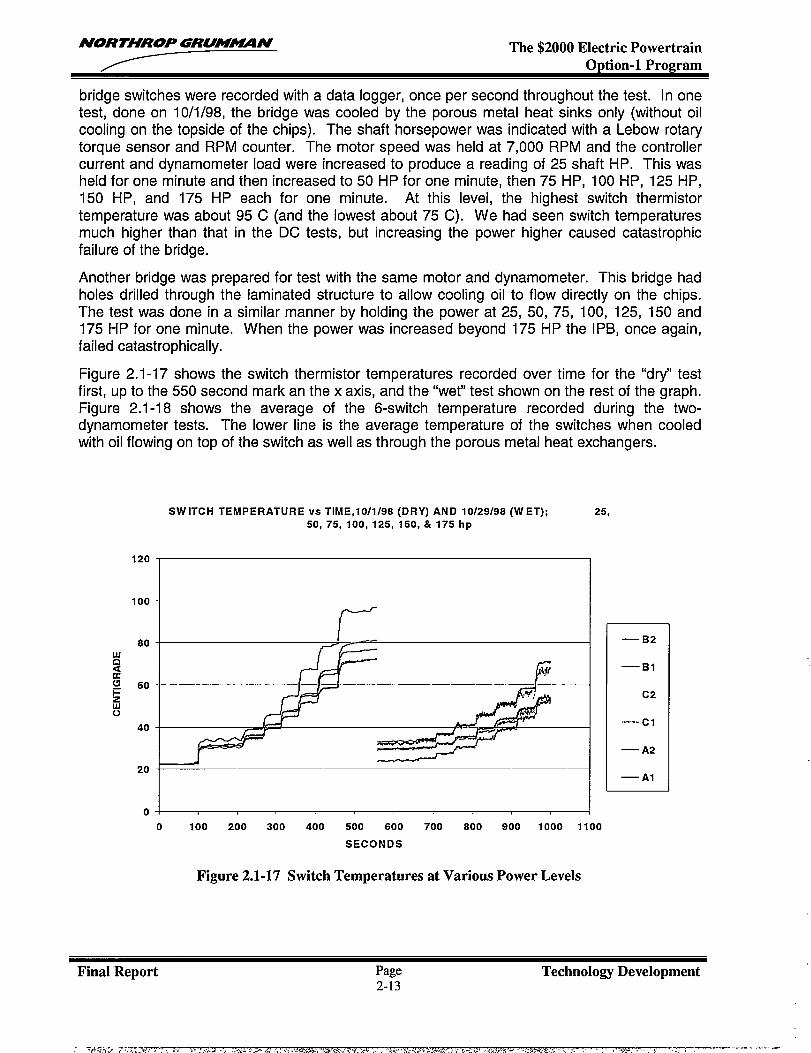
bridge switches were recorded with a data logger, once per second throughout the test. In onetest, done on 10/1/98, the bridge was cooled by the porous metal heat sinks only (without oilcooling on the topside of the chips). The shaft horsepower was indicated with a Lebow rotarytorque sensor and RPM counter. The motor speed was held at 7,000 RPM and the controllercurrent and dynamometer load were increased to produce a reading of 25 shaft HP. This washeld for one minute and then increased to 50 HP for one minute, then 75 HP, 100 HP, 125 HP,150 HP, and 175 HP each for one minute. At this level, the highest switch thermistortemperature was about 95 C (and the lowest about 75 C). We had seen switch temperaturesmuch higher than that in the DC tests, but increasing the power higher caused catastrophicfailure of the bridge.
Another bridge was prepared for test with the same motor and dynamometer. This bridge hadholes drilled through the laminated structure to allow cooling oil to flow directly on the chips.The test was done in a similar manner by holding the power at 25, 50, 75, 100, 125, 150 and175 HP for one minute. When the power was increased beyond 175 HP the IPB, once again,failed catastrophically,
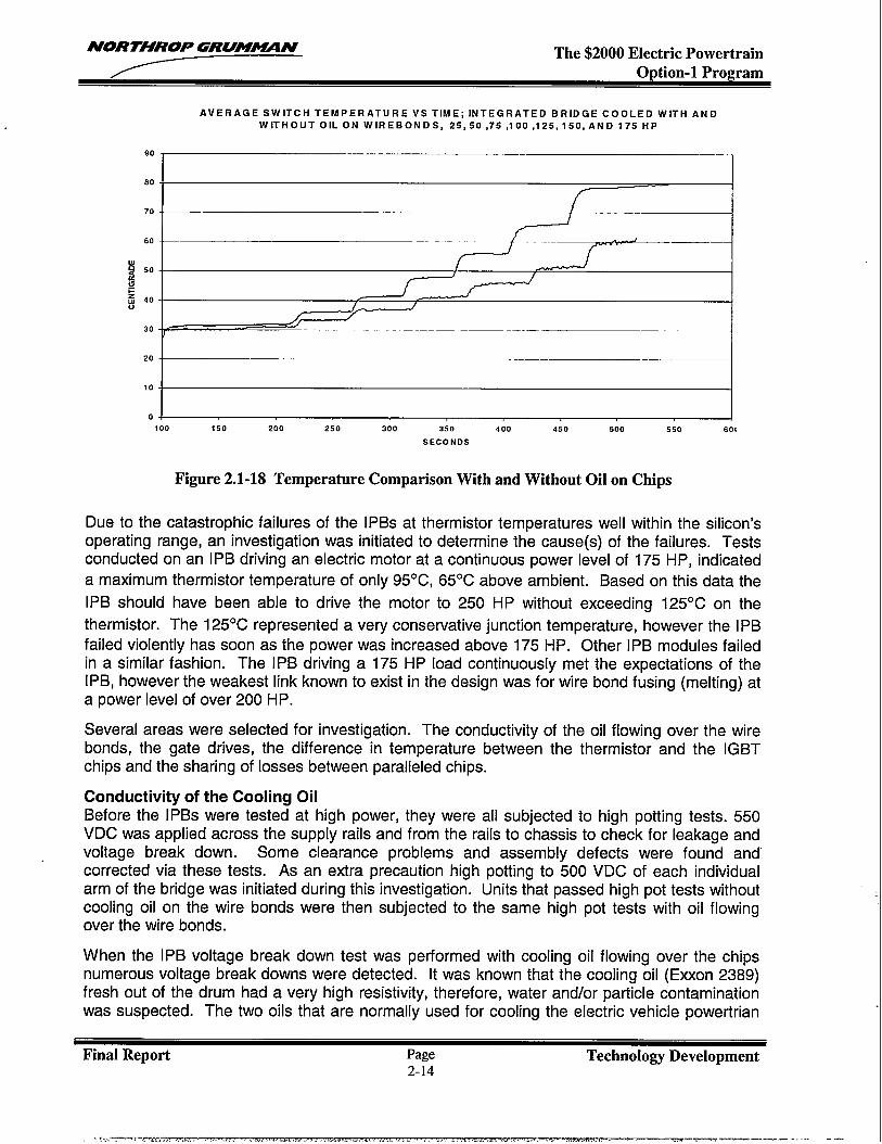
Figure 2.1-17 shows the switch thermistor temperatures recorded over time for the “dry” testfirst, up to the 550 second mark an the x axis, and the “wet” test shown on the rest of the graph.Figure 2.1-18 shows the average of the 6-switch temperature recorded during the two-dynamometer tests. The lower line is the average temperature of the switches when cooledwith oil flowing on top of the switch as well as through the porous metal heat exchangers.
SWITCH TEMPERATURE VS TIME,10/1/98 (DRY) AND 10/29/98 (WET); 25,
50, 75, 100, 125, 150, & 175 hp
100
80
60
40
20
(-
0 I
0 100 200 300 400 500 600 700 800 900 1000 1100
SECONDS
Figure 2.1-17 Switch Temperatures at Various Power Levels
—B2
—B1
C2
—cl
— A2
— Al
Final Report Page Technology Development2-13
.. -iti:+-! 7.-,-,—--- - - --- -
NORTHROP GRUM~N The $2000 Electric PowertrainOption-1 Program
AVERAGE SW IT CHTEMPER AT UREVSTIM E; INTEGRATED BRIDGE COOLED WITH ANDWIT HO UT OIL ON WIRE BONDS, 25,5 0,75,100,125, 150, AND 175 HP
90I I
80
70I,
I /= IF ‘- --~—-l-1 t I
i
20~”-------—– -110
i0 -1 I100 150 200 250 300 350 400 450 500 550 601
SECONOS
Figure 2.1-18 Temperature Comparison With and Without Oil on Chips
Due to the catastrophic failures of the [PBs at thermistor temperatures well within the silicon’soperating range, an investigation was initiated to determine the cause(s) of the failures. Testsconducted on an IPB driving an electric motor at a continuous power level of 175 HP, indicated
a maximum thermistor temperature of only 95°C, 65°C above ambient. Based on this data the
IPB should have been able to drive the motor to 250 HP without exceeding 125°C on the
thermistor. The 125°C represented a very conservative junction temperature, however the IPB
failed violently has soon as the power was increased above 175 HP. Other IPB modules failedin a similar fashion. The IPB driving a 175 HP load continuously met the expectations of theIPB, however the weakest link known to exist in the design was for wire bond fusing (melting) ata power level of over 200 HP.
Several areas were selected for investigation. The conductivity of the oil flowing over the wirebonds, the gate drives, the difference in temperature between the thermistor and the IGBTchips and the sharing of losses between paralleled chips.
Conductivity of the Cooling OilBefore the IPBs were tested at high power, they were all subjected to high potting tests. 550VDC was applied across the supply rails and from the rails to chassis to check for leakage andvoltage break down. Some clearance problems and assembly defects were found andcorrected via these tests. As an extra precaution high potting to 500 VDC of each individualarm of the bridge was initiated during this investigation. Units that passed high pot tests withoutcooling oil on the wire bonds were then subjected to the same high pot tests with oil flowingover the wire bonds.
When the IPB voltage break down test was performed with cooling oil flowing over the chipsnumerous voltage break downs were detected. It was known that the cooling oil (Exxon 2389)fresh out of the drum had a very high resistivity, therefore, water and/or particle contaminationwas suspected. The two oils that are normally used for cooling the electric vehicle powertrian
Final Report Page Technolo~ Development2-14
>r<,,— F.-l-,,-.,. . . . . . . . . . . . . . . . . ..-. ., . . .,. .<—--— ~- —— ——. ., --- —
NORTHROP GRUM~N The $2000 Electric PowertrainOption-1 Program
systems (Exxon 2389 and Braco 881) were found to be hydroscopic (will absorb moisturedirectly from air). To avoid the possibility of water and eventually acid contamination of the oil a
fresh supply of Royco 602 was obtained for use in further testing. This oil is >98% PAO
(polyalphaolefin) and is not hydroscopic. High pot tests were now run with a much highersuccess rate. Only IPBs that passed the oil immersed high pots tests were used for furthertesting in oil.
Gate Drive InvestigationThe paralleled IGBT chip arrangement used in each pole of the IPB was also used in acommercial IGBT module. The data sheets for this module provide dynamic characteristicsusing a +/-15 VDC gate drive with 15 Ohms for a turn on resistance and O Ohms for a turn offresistance. The gate drive used during high power motor drive tests also has +/-1 5 VDCsupplies but has 12.5 Ohms for both turn-on and turn-off. This raised a concern that the IGBTgates were neither being turned off nor held off hard enough.
When an “off” IGBT is subjected to the reverse recovery of its freewheeling diode, the collectorvoltage rises quickly from a level close to zero to a level close to full link voltage. This highdv/dt causes current to flow through the collector/gate capacitance and raises the gate/emittervoltage. If the gate is not biased off through a sufficiently low impedance this rise ingate/emitter voltage can turn “on” the supposedly “off” IGBT. This can lead to a shoot-throughcondition destroying the pole. The switching waveforms of the IPB were examined for any signof this problem.
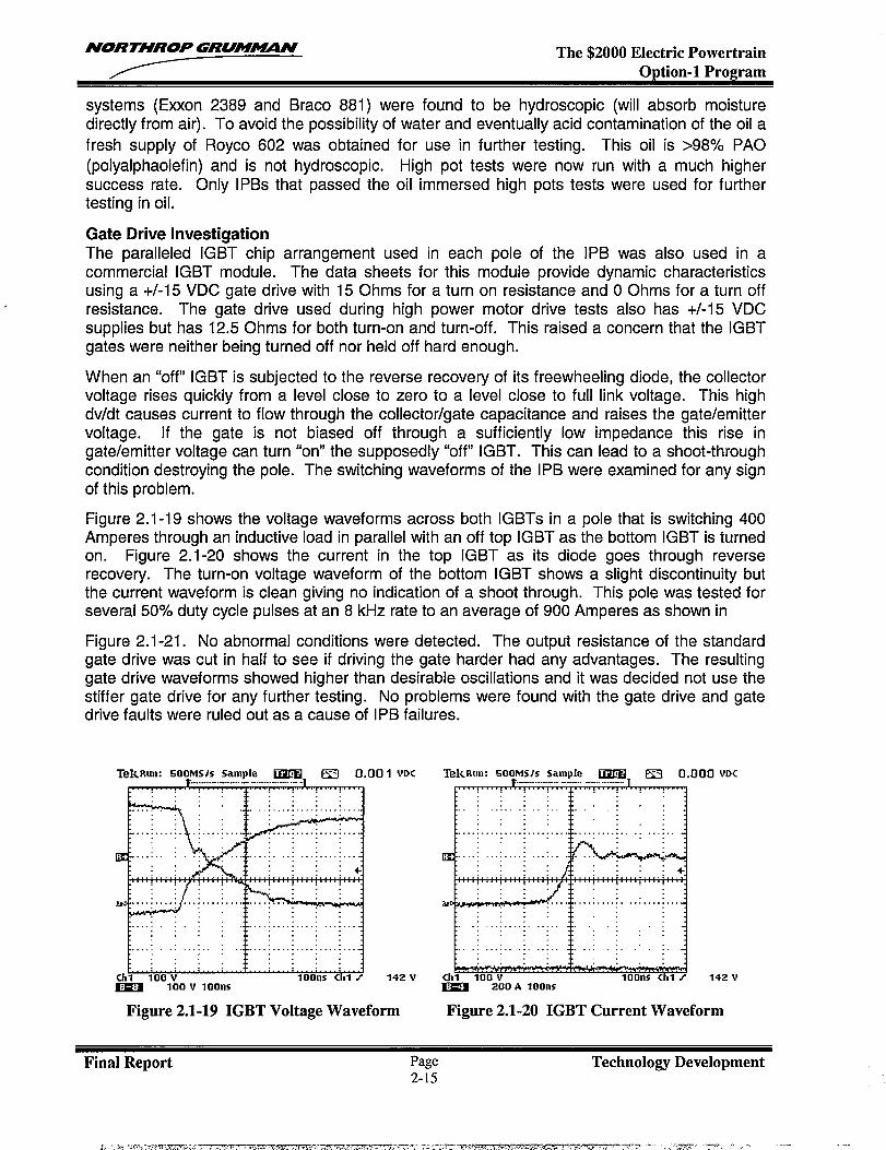
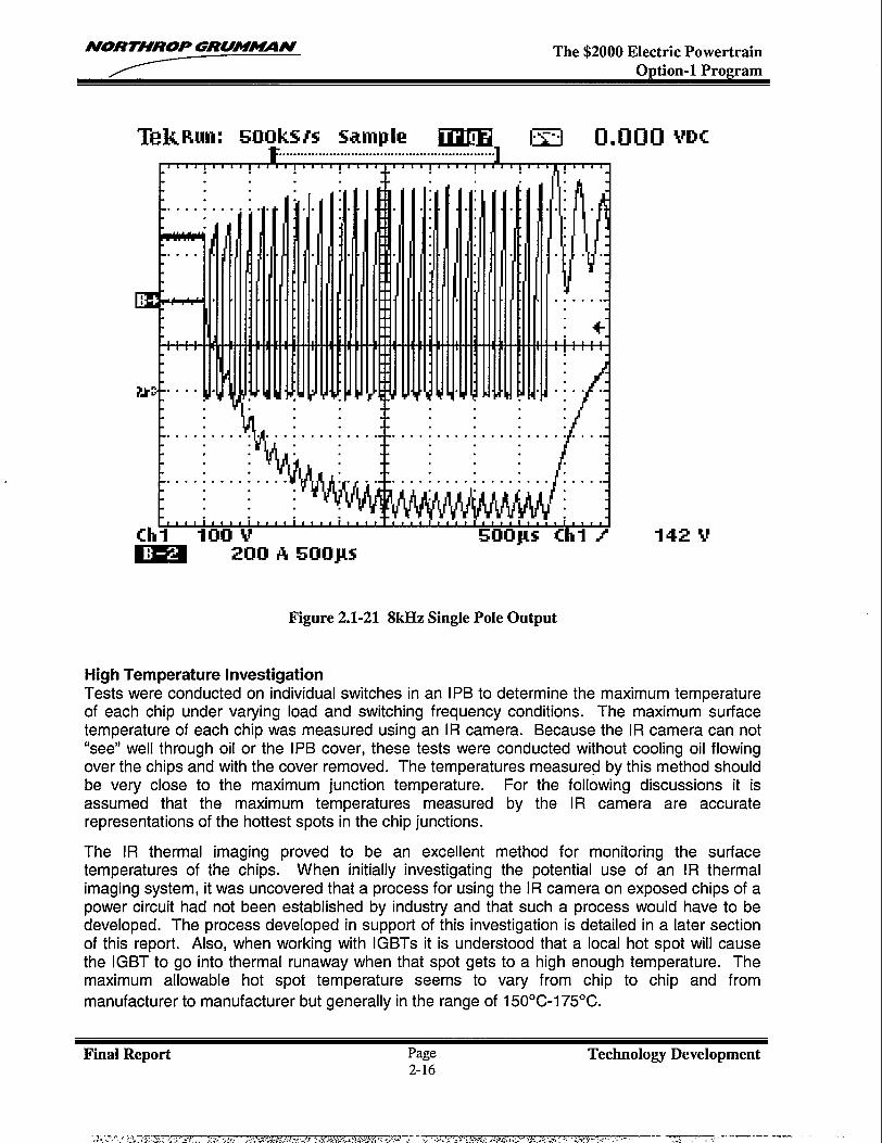
Figure 2.1-19 shows the voltage waveforms across both IGBTs in a pole that is switching 400Amperes through an inductive load in parallel with an off top IGBT as the bottom IGBT is turnedon. Figure 2.1-20 shows the current in the top IGBT as its diode goes through reverserecovery. The turn-on voltage waveform of the bottom IGBT shows a slight discontinuity butthe current waveform is clean giving no indication of a shoot through. This pole was tested forseveral 507. duty cycle pulses at an 8 kHz rate to an average of 900 Amperes as shown in
Figure 2.1-21. No abnormal conditions were detected. The output resistance of the standardgate drive was cut in half to see if driving the gate harder had any advantages. The resultinggate drive waveforms showed higher than desirable oscillations and it was decided not use thestiffer gate drive for any further testing. No problems were found with the gate drive and gatedrive faults were ruled out as a cause of IPB failures.
TekRun: 500MS1SSawie UWEil (53 0.00. . . . . . . . .. .t“”’;’”’”:’’’’:’’’”:’’’”k~ . .
1 VDC
,h~ ,4*Vm 100 V loons
Figure 2.1-19 IGBT Voltage Waveform
TekRun: 500MS/s sdmple ~ ~ 0.000 VDC.— ..— .-— —. ..—-..
-.
L::: :. . i“”:’ :“::: : :.:.
. . . . . . .: ...:, . . . . . . ..: .: ..’ :..i
:.. .chl 100 Vm
loons Chl z 142 V200 A 10ons
Figure 2.1-20 IGBT Current Waveform
Final Report Page Technology Development
NORTHROP GRUM~N The $2000 Electric PowertrainOption-1 Program
............................................................
L“’’!’’’’!’’’’!’’’’!’’’’+’’’’!””! “’’!”E : : : .:
L . . . . . . . ..-. l.m. . . .
E :‘f. Vflfl..
. . . . . .
i.i
. . . . . . . . . . . .‘II . .
. .
“1
.
L.. WI E%J,.:/1.,. . . . . . . . . . . . . . . . . . . . . . . . . . .. . . . . . . . . . . . .
. .: ‘:M@q~lv/..w( ~
.thi 100 i “ “,t,,1 , * m * I , * , * I , , t * 1 * * , , , , t , I , * , , * , * * I * 1
5mus thl # 142 sma Wlcl A 5tmJ.M
.
Figure 2.1-21 8kHz Single Pole Output
High Temperature InvestigationTests were conducted on individual switches in an IPB to determine the maximum temperatureof each chip under varying load and switching frequency conditions. The maximum surfacetemperature of each chip was measured using an IR camera. Because the IR camera can not“see” well through oil or the IPB cover, these tests were conducted without cooling oil flowingover the chips and with the cover removed. The temperatures measured by this method shouldbe very close to the maximum junction temperature. For the following discussions it isassumed that the maximum temperatures measured by the IR camera are accuraterepresentations of the hottest spots in the chip junctions.
The IR thermal imaging proved to be an excellent method for monitoring the surfacetemperatures of the chips. When initially investigating the potential use of an IR thermalimaging system, it was uncovered that a process for using the IR camera on exposed chips of apower circuit had not been established by industry and that such a process would have to bedeveloped. The process developed in support of this investigation is detailed in a later sectionof this report. Also, when working with IGBTs it is understood that a local hot spot will causethe IGBT to go into thermal runaway when that spot gets to a high enough temperature. Themaximum allowable hot spot temperature seems to vary from chip to chip and from
manufacturer to manufacturer but generally in the range of 150”C-I 75”C.
Final Report Page Technology Development2-16
-,?,-,~,..,, ;.,—,?.=, ! ,. ,,/. y ..-,,,. ,. . .. . . . . . .s .. .. ...?..$.,. ,* +.,,* $<--, . ,.:,+-/ 7 . .w7--- -— —. . ....”--” —--- -- --
NORTHROP GRUMXIMN The $2000 Electric PowertrainOption-1 Program
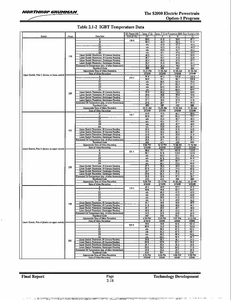
Three switches were tested with load currents of 110 and 220 Amperes at DC and at three ACswitching frequencies (4, 8 and 12 kHz, each with a 50% duty cycle). During the DC tests,saturation voltages across the IGBTs were measured to provide an accurate power loss in eachswitch. The DC input voltage during these tests was 340 Volts. The data collected is shown inTable 2.1-2.
Since the power lost in each chip was not known, an effective thermal resistance had to becalculated. The effective thermal resistance can be calculated by taking the greatesttemperature rise between the cooling oil and surface of the chip and dividing it by the averagepower lost in that switch. The three switches tested had effective thermal resistances between
0.163 and 0.248 OC/Watt. The cause of the large variation was not determined but it may be
due to differences in mounting, differences in chips and how well the two parallel IGBT chipsshared the losses.
In previous calculations of thermal resistance, it was assumed that the temperature of thethermistors provided a good estimate of the chip temperatures. This was shown not to be thecase indicated in the data of Table 2.1-2. The chip temperatures were much higher than the
thermistor temperatures, by as much as 46°C for the lower switch in pole-C running at 220Amperes and 12 kHz. When the data logger temperatures are corrected for the proper
thermistor curve this maximum difference increases to about 51 “C, almost half of the rise from
cooling oil to chip. This indicates that the thermistors on the chip carriers should not be used tomonitor junction temperatures of the chips.
In general the temperatures of the two IGBT chips in each switch are fairly close (AT < 4°C)during the DC tests. This indicates that the two chips are sharing conductive losses fairly well.When switching losses are introduced the differences become much greater. In the case of the
lower switch in pole-C, the AT actually changes sign. At DC, 11 appears to have slightly moreconduction losses than 12 but when switching, 12 has much higher temperatures than 11. Thisindicates that 12 is taking more of the switching losses than 11. Matching IGBTs to shareconduction losses is standard practice but forcing them to share switching losses is much moredifficult. This inability to share losses must be accounted for in the maximum power rating of
paralleled IGBTs. The lower switch in pole-C has the worst AT between IGBT chips and a
thermal resistance of 0.185 OC/W. If the worst AT and the highest thermal resistance occurredon the same switch, the chip temperatures would be even higher and the power rating would befurther reduced. The switching losses from the lower switch in pole-C and the effective thermalresistance of the upper switch in pole-C (highest thermal resistance) will be used to estimate aworst case temperature rise of an IPB chip while driving a motor.
By using the thermal resistances calculated from DC data and the temperature rise of the chipsduring switching, the switching losses in the IGBT chips can be estimated. For the lower switch
in pole-C, the total losses at 8 kHz and 220 Amperes are estimated to be (113 ‘C – 27.2 0
C)/(0.l 85 OC/W) = 464 Watts. The conduction losses are estimated to be half the DC losses at220 Amperes or 161 Watts. The switching losses are the difference or 303 Watts. The actualswitching frequency for the 8 kHz tests was 7827 Hz, which is the motor drive PWM frequency.The energy lost per cycle at 220 Amperes is therefore 303/7827 or 0.039 Joules. The IGBTcollector/emitter saturation voltage measured during testing was 1.5 Volts at 220 Amperes and1.9 Volts at 440 Amperes. This agrees very well with the manufacturer’s typical switching lossand saturation voltage data.
Final Report Page Technology Development2-17
- ,,:, -, . 77-.r;.m,3?c r . . 7-= -,-. .. . .. -x?? . ,.~.m,t?...>. ,,..,..- ... . ... . ~.. = .-. ..-. .—. - —.. — .—
NORTHROP GRUM’N The $2000 Electric PowertrainOption-1 Program
Table 2.1-2 IGBT Temperature Data
.%tch I I Dc POww w I Temp e C) ~emp e C) at Frequency W “k Duty Cycle) m kHir%lps Data hem Total ~1+&2) Dc A 8 I 12
Rn 677I I 11I I m5 I 51.6 I ~
“ 1335 m. 40-, ,
I I. I ! 4. I -.. I J
01 da 438 A
02 I I da I 439 I 4M .,. ,3 r “
Jppw Svatch, POIBC (d!odes on Imvw ,,3154
Y) n 1 mz I 11
Q 939 7s.1 9D1 da 655 I 602 nfa 671 6n. .,= c“ c I c
. .
1 *P oxgmatelime of Vid.m Recordina 12.:m.. - -, . . ..- m----- -- 2X
I 11 1407 54.9 I 47.5 I 5R 533 4?7
c
I D1 I I da I 4
02 tia 4m a 1 .,. I “
----; 1- 103063 70064 713
,.. -. ! &3 6s0m nfa 653 655 695
22UUpper %ntch Thermistor, [R Camera Readinq m9 630 739 836Lmver %fch Thermistor, IR Cameta Readinq 268 40.6 339 436Upper Swfch Thermistor. Oatalogger Reading 722 6T8 734 947Lower %fch Thermistor. Oataloqger Readmq 271 33.5 379 416
Estunated Oil Temperature (avg. of other Iherm!slors) 270 2a.1 277 5n3Thumbnad Code 5329 m7 Pn2 m5
21 m 11.55AM llmw 1133AMmE3 2L?3JW mm X23&3
8.7 695v., 44 7911.3 4s7 4942.4 471 A98
, ,.. , .0.5 457 d8 O04 42.6 4s8 d9 1
110Upper Swfch Thermistor. IR Camera Readinq ~5 3.6 316 346fmwr %itch Thermistor. IR Camera Readinq 419 424 454 5S7Upper Swdch Thermistor, Datalogqer Readmq 248 37 238 319Lmw Swfch Thermistor, Datalogqer Readw 456 428 451 551
Est[mated 011Temperature (aw of other themustors) 256 2G1 253Thumbnad Code
2%4m Al 1 m m
APPoxima 13PM 12.13 Phl llmmd 11 10AMDatt., .Lu=. “=..l.l,,{ ~m 2tt9ET 2n6a3 m
I -.110 1220130 141021 78850 81097 774
, ,.. ! CF.,., , ,3.0 EO.8
27.0Upper Swfch Tlennistor. IR Camera Reading 271 %.3 403 436fmver SwWh Thermistor. IR Camera Reading 679 63.2 744 836Upper %tch lhennistor, Oatalogqer Reading 257 39.0 =6 416Imver ‘%tch Thermistor. Datalogger Reading 690 E6.4 715 947
Est[mated 011Temperature (avg. of other thetm!stors) 238 290 272 267Thumbnml Code A1O A12 .KM S03
4P ox#mateTime of Video Recordmq 5.06 Phf 12.13 PM llm,.ui 11 IOAMOale of Video Recording mm Z1 9/59 mm 2rz3m
>7 =JG
over Swch. Pole A (diodes on woer
ale lime of Video Recording 50,. . ...%... 0..-4, ?g m
11321.4
93.0 79.1 1[f2 S51 816 11D1 Ma 63.2 702 da 676 7m rda m7 6n“ .,. cc. 7
.. .
I t 11
I1433
493 I 44.9 I 5Q 500 4E’ .
I I 01 I I da I 402 nla 4m I I .,. I *
lte Xme of Video Recordmq I I 4:....,..”. n.-. ~,.. -,,
II3239
m6 7D.8Q m.6 747
01 da 5502 da S.L .m Ma 9.2 I em, “,. =? .
46 1010..- -1.3 11409.2 I 612 62242 V5 591
Da 620
1 ,“. , w.. , &6 5s4
220Upper %lch Thermistor, IR Camera Readmq 268 3S.1 33.7 370Lmver %tch Thermistor, [R Camera Readinq m9 57.6 621 765Upper Swtch Thermistor. Datalogger Reading 261
LWEr %fCh ThetfIIiStOr, Oatalower Readinq
35.4 353 356596 5S.5 CM5 719
Estimated Oil Temperatum (w. of other Iherm!stors) 259 25.d 257 259Thumbnad Code Al O B11 B13 5!15
APP oxlmate Km< “3PM 3.26 PM 4.C5 PM 422PMDate of Wseo Ne.om ..- ..- 4J9,S+3 4J9,93
e of Video Recordmq I I 43. . . . . . . . dmq 2ff- ! .-
Final Report Page Technology Development2-18
NORTHROP GRUM~N The $2000 Electric PowertrainOption-1 Program
Formulas for calculating the losses per switch in a three-phase PWM drive can be found in thePOWEREX@ Applications and Technical Data Book. Using these formulas and themeasured/calculated values above, the switch with highest losses would dissipate 600 Watts inthe IGBT chips when driving a motor at 175 HP. Using the highest effective thermal resistance
(without oil flowing on top of the IPB) of 0.248 OC/W, the worst case temperature rise of the
chips could be as much as 149 “C. If maximum values (from the chip manufacturer’s data
sheets) are used for the collector/emitter saturation voltages, this temperature could be has
high as 180 “C. Higher still if worst case switching losses are used.
With oil flowing over the chips the thermal resistance and temperature rise would be reduced.How much should be the object of further study. Even if we assume the effective thermalresistance is reduced to 75% of the above values, the temperature rise would still be at least
112 “C. This would produce junction temperatures too close to the maximum rating of 150 “C.
Conclusions of the InvestigationAlthough the investigation was not absolutely conclusive as to the cause of the IPB failures athigh power levels, many of the suspect causes were eliminated. If the IR camera thermal datais accurate then thermal stress within the IGBTs is evident. It is likely that the inability of theIGBTs to share switching losses equally and the worst case effective thermal resistance of theIPB would lead to a thermally over-stressed IGBT when trying to drive a motor above 175 HP.It should also be noted that in discussions with various IGBT manufacturers during the courseof this investigation, the manufacturers all considered their processes of balancing switchinglosses between parallel IGBT chips as proprietary.
2.1.4.5 IPB Silicon Chip Temperature Measurement
The basic IPB was designed with thermistors placed in predefine locations to providetemperature information during test and operation of the IPB. This method of measuringtemperature is limited by the fact that only the local temperature in the area surrounding thethermistor is measured. We utilized these thermistors in most of the IPB testing, however, aswe pushed the IPB towards the limits of its capability it was decided that a more robust methodof measuring IPB temperature was needed. The goal was to find a method of determiningtemperatures of the chips themselves and the temperatures of the wire-bond connections. Thiswill allow us to accurately set a maximum operating power that has a reasonable margin ofsafety. It can also be used to verify thermal models.
It is difficult to measure the actual temperature of the junction(s) in a silicon chip. Additionalthermistors can be glued to the top surface, but they measure the temperature of those pointsonly. [t cannot provide a temperature map of the whole surface. Thus, it is possible that thethermistor is not located on the hottest spot. The thermistor also occupies some surface areathat might be used for wire-bonds. The thermistor wires must also be routed to a data logger,adding additiorl wiring operations. A small temperature probe is not useful here either. Directprobing of the IPB may lead to shorting the chip or damaging the chip or its wire-bonds duringprobing. Getting a temperature map of the silicon surface would be very time consuming andprone to operator error. In addition, the IPB operates at hazardous voltage levels.
Infrared (IR) thermal imaging offers a promising method of measuring silicon surfacetemperatures. An IR camera allows you to determine a temperature profile for all surfaces inthe camera’s field of view. In theory, we should be able to aim the camera at the IPB and gettemperature readings for all the chips. A successful method of using IR was investigated and itis detailed below.
Final Report Page Technology Development2-19
1J ..:-“-,:.,.p,:n>r~~::-;- ,.,:,.*’., :~.r-~~ .,,,,,----.:-.?>:7—,-FT.-, /,.-....~.,.,4.:.,~~,~~~ -V= -.— ,-..-–——----- -- ----—-/.,-<.<...,..,:.,..W-,..,;
NORTHROP GRUM-N The $2000 Electric PowertrainOption-1 Program
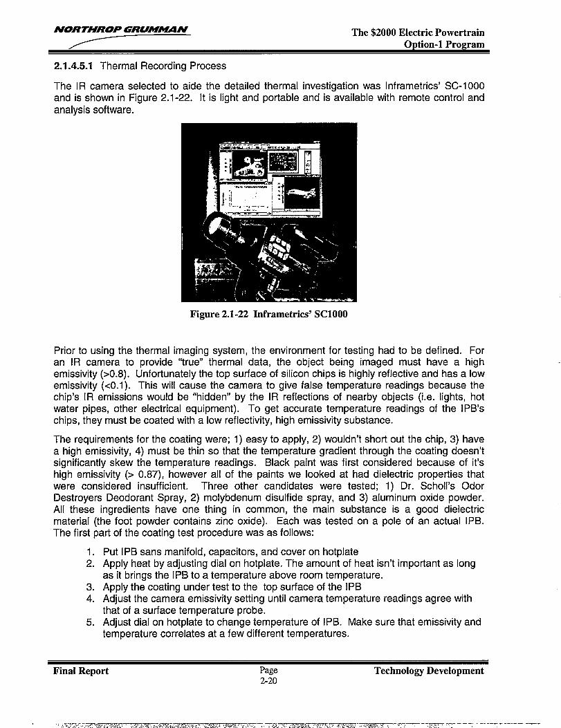
2.1.4.5.1 Thermal Recording Process
The IR camera selected to aide the detailed thermal investigation was Inframetrics’ SC-1000and is shown in Figure 2.1-22. It is light and portable and is available with remote control andanalysis software.
Figure 2.1-22 Inframetrics’ SC1OOO
Prior to using the thermal imaging system, the environment for testing had to be defined. Foran IR camera to provide “true” thermal data, the object being imaged must have a highemissivity (>0.8). Unfortunately the top surface of silicon chips is highly reflective and has a lowemissivity (<0.1). This will cause the camera to give false temperature readings because thechip’s IR emissions would be “hidden” by the IR reflections of nearby objects (i.e. lights, hotwater pipes, other electrical equipment). To get accurate temperature readings of the IPB’schips, they must be coated with a low reflectivity, high emissivity substance.
The requirements for the coating were; 1) easy to apply, 2) wouldn’t short out the chip, 3) havea high emissivity, 4) must be thin so that the temperature gradient through the coating doesn’tsignificantly skew the temperature readings. Black paint was first considered because of it’shigh emissivity (> 0.87), however all of the paints we looked at had dielectric properties thatwere considered insufficient. Three other candidates were tested; 1) Dr. Scholl’s OdorDestroyers Deodorant Spray, 2) molybdenum disulfide spray, and 3) aluminum oxide powder.All these ingredients have one thing in common, the main substance is a good dielectricmaterial (the foot powder contains zinc oxide). Each was tested on a pole of an actual IPB.The first part of the coating test procedure was as follows:
1.2.
3.4.
5.
Put IPB saris manifold, capacitors, and cover on hotplateApply heat by adjusting dial on hotpiate. The amount of heat isn’t important as longas it brings the IPB to a temperature above room temperature.Apply the coating under test to the top surface of the IPBAdjust the camera emissivity setting until camera temperature readings agree withthat of a surface temperature probe.Adjust dial on hotplate to change temperature of IPB. Make sure that emissivity andtemperature correlates at a few different temperatures.
Final Report Page Technology Development2-20
NORTHROP GRUMAUIN The $2000 Electric PowertrainOption-1 Program
With the above procedure the emissivity of each coating can be determined. The molybdenumdisulfide spray and the aluminum oxide powder had emissivities in excess of 0.75, which issufficient for our needs. Since it was in a spray can, the molybdenum disulfide was easy toapply. The aluminum oxide powder had to be sprinkled on the IPB (using a powdered sugarshaker). With practice, it was possible to get consistent emissivity readings on the camera.The foot powder proved difficult to apply. Unless sprayed on thick, it always left much of thesurface visible. When sprayed on thick, it was lumpy and uneven. It was difficult to getconsistent emissivities for the spray. The foot powder was removed from the candidate list.
The remaining two candidate coatings were then tested for voltage breakdown. Each wassprayed on a single pole of the IPB and high voltage was applied. The pole coated withmolybdenum disulfide immediately shorted and failed. It was suspected that the spraypropellant was a poor dielectric and thus caused the voltage breakdown. The aluminum oxidepowder passed the high voltage test. The emissivity of the Aluminum Oxide was measured tobe 0.75 using the procedure listed above.
2.1.4.5.2 IPB Testing
The IPB module was mounted into our dynamometer fixture, the electrical connections weremade and cooling lines were attached. As indicated in Figure 2.1-23, the IPB cover wasremoved and the snubber capacitors were moved to the side to allow the camera to have aclear view of all of the IPB’s chips. Aluminum oxide powder was sprinkled on the surface of thepole(s) to be tested and the IR camera was mounted above the IPB at a focal distance thatallowed each pole to be imaged individually.
Each switch was tested at 110 Amps and 220 Amps. For each current level, tests were run atswitching frequencies of 4 kHz, 8 kHz, and 12 kHz and DC. During each test level, the siliconwas allowed to reach steady state. Using the IR camera, the hotspots in each silicon chip werenoted and an IR image of the pole under test was recorded. It should be noted that the IRcamera actually measured the temperature of the aluminum oxide powder coating not thesilicon. It is assumed that the temperature gradients from the top of the chip to the top of thepowder layer were minimal.
Capacitors moved out ofhe way during ksdng
Figure 2.1-23 IPB Showing IR Image Area
2.1.4.5.3 Results
Final Report Page Technology Development2-21
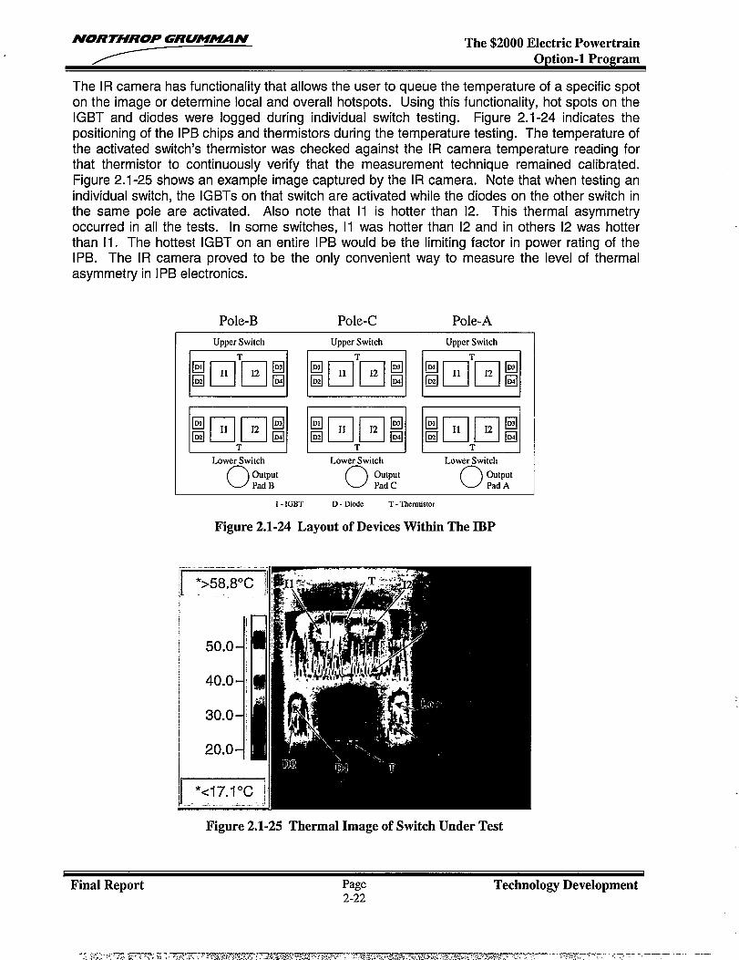
NORTHROP GRUMMN The $2000 Electric PowertrainOption-1 Program
The lR camera has functionality that allows the user to queue the temperature of a specific spoton the image or determine local and overall hotspots. Using this functionality, hot spots on theIGBT and diodes were logged during individual switch testing. Figure 2.1-24 indicates thepositioning of the IPB chips and thermistors during the temperature testing. The temperature ofthe activated switch’s thermistor was checked against the IR camera temperature reading forthat thermistor to continuously verify that the measurement technique remained calibrated.Figure 2.1-25 shows an example image captured by the IR camera. Note that when testing anindividual switch, the IG BTs on that switch are activated while the diodes on the other switch inthe same pole are activated. Also note that 11 is hotter than 12. This thermal asymmetryoccurred in all the tests. [n some switches, 11 was hotter than 12 and in others 12 was hotterthan 11. TheIPB. The [Rasymmetry in
hottest IGBT on an entire IPB would be the limiting factor in power rating of thecamera proved to be the only convenient way to measure the level of thermalIPB electronics.
Pole-B Pole-C Pole-A
Upper Switch Upper Switch Upper Switch.-
I 1 1 1 1 I
EE!EIE!EWLower Switch Lower Switch
o output o outputPad B Pad C
Lower Switch
o outputPad A
I - IGBT D - Dixie T- Thermistor
Figure 2.1-24 Layout of Devices Within The IBP
Figure 2.1-25 Thermal Image of Switch Under Test
Final Report Page2-22
Technology Development
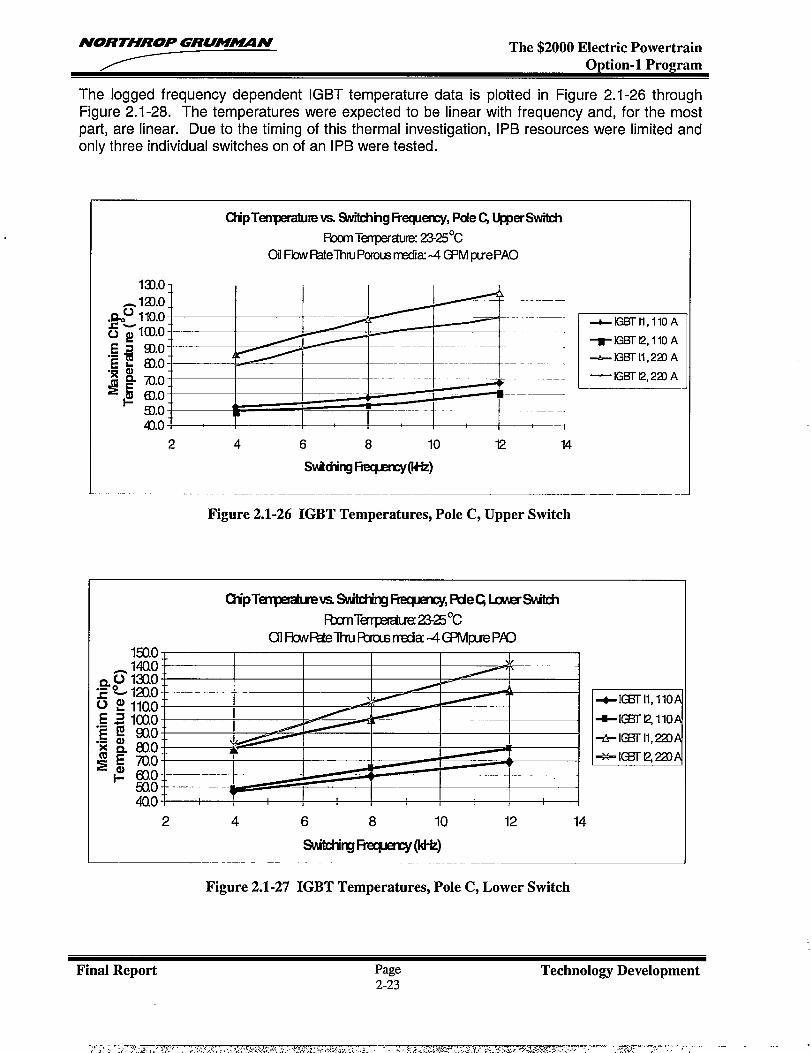
NORTHROP GRU!MN The $2000 Electric PowertrainOption-1 Program
The logged frequency dependent IGBT temperature data is plotted in Figure 2.1-26 throughFigure 2.1-28. The temperatures were expected to be linear with frequency and, for the mostpart, are linear. Due to the timing of this thermal investigation, IPB resources were limited andonly three individual switches on of an IPB were tested.
CtipTeqxxature vs %itctingl%ecpercy, Pde Q ~er%vitch
RxmTenpwtLIE 2W5°COi Flw RatelhruPcmusrnsdku4 CPM puePAO
131.OT i T T T r
-120.0..%” 110.0~ ~lco.o
m.o ~I I I I
6).09).0-4).0
2 4 6 8 10 12 14
SvMingktpmy(ltk)
Figure 2.1-26 IGBT Temperatures, Pole C, Upper Switch
-IGBTII, I1OA
TlGBTt2,110A
-&lGBTll,2a A
— IGBT t2, 223 A
1500
4002 4 6 8 10 12 14
switdirgR?qEmy(kHz)
+- IEETH,11O
-EETQ11O
+IQ31-11,2Z
Figure 2.1-27 IGBT Temperatures, Pole C, Lower Switch
Final Report Page Technology Development2-23

NORTHROP GRU!#IUIN The $2000 Electric PowertrainOption-1 Program
123.0
400
1A
. /__— —
-1I
2 4 6 8 10 12 14
SvuitingFqmq@-tz)
u+G5Tll, 110
-a-ml~llo
+iGB-rll,20
*lGf3r12z20
Figure 2.1-28 IGBT Temperatures, Pole A, Lower Switch
2.1.5 Conclusions
The Integrated Power Block effort was a great success. The final IPB design exceeded almostevery expectation. The IPB reduced the parts count by more than 50% over the bridge designthat is used in the production system. Its low inductance improves the voltage overshoot by3:1. And the IPB manufacturing cost is projected to be 40% of the cost of the productionbridge. A summary of the achievements that resulted from this effort are listed below.
1)
2)
3)4)
5)
6)
60% reduction in the cost of the powertrain bridge.. Used ?4 of the silicon used in the production powertrain bridge. Reduced the heat sink cost by over 20:1
Improved the thermal resistance by more than 2:1 (3:1 when flowing cooling oil directlyover chips).Reduced power bridge volume by almost 3:1 and weight by 4:1Superior electrical performance
. Reduced overshoot by 677.● Smaller snubber capacitors. Better Inductance characteristics
Advanced assembly process for an integrated power block● Void-free solder attachment of large size semiconductor chips to metal carriers.. Solder attachment of the sub-assemblies (semiconductor devices and metal
carrier) on the liquid cooled bus bars of the inverter assembly.● Wire bonding of large size (0.020” & 0.025” diameter) aluminum wire. The final assembly processes, for attachment of discrete gate drive components
and thermistors.. Switch screening, and final electrical test
IR imaging of silicon power devices
The proof of principal demonstration of the IPB concept has shown great promise. Theaccomplishments obtained in this phase have given rise to suggestions for further experimentsas listed below.
Final Report Page Technology Development2-24
NORTHROP GRUM~N The $2000 Electric PowertrainOption-1 Program
1. Measure the improvement to the thermal resistance of a flooded IPB vs. thenon-flooded IPB. The investigation during this project defined an approachthat proved to be successful for flowing cooling fluid directly over the highvoltage power electronic devices. Although the process was successful, theincreased thermal performance is not known. It would be worth while toknow if this cooling process could be applied to electric vehicles.
2. Determine chip temperatures while operating all three phases of the IPBunder a load (i.e. 230 HP motor). The goal here would be to show that oneIPB could do the work of at least two bridges in our existing powertrainsystems.
3. Compare paralleled IGBTs feeding a single motor winding to series IGBTsfeeding paralleled motor windings. The goal would be to define an electricmotor drive that would eliminate the highly proprietary process of matchingIGBTs chips.
4. Continue to search for high emissivity, high dielectric coatings that are easierto apply than aluminum oxide powder. [f one can find a coating that can beeasily used during assembly, it would be possible to use IR imaging as aninspection process during testing preformed in manufacture.
5. Use available macro lens to determine quality of wire bonds. If ail wire bondsare sharing current equally, they should all be roughly the same temperature.
Final Report Page Technolo~ Development2-25
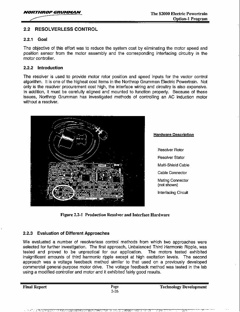
NORTHROP GRUM~N The $2000 Electric PowertrainOption-1 Program
2.2 RESOLVERLESS CONTROL
2.2.1 Goal
The objective of this effort was to reduce the system cost by eliminating the motor speed andposition sensor from the motor assembly and the corresponding interfacing circuitry in themotor controller.
2.2.2 Introduction
The resolver is used to provide motor rotor position and speed inputs for the vector controialgorithm. It is one of the highest cost items in the Northrop Grumman Electric Powertrain. Notonly is the resolver procurement cost high, the interface wiring and circuitry is also expensive.In addition, it must be carefully aligned and mounted to function properly. Because of theseissues, Northrop Grumman has investigated methods of controlling an AC induction motorwithout a resolver.
Hardware Descrbtion
Resolver Rotor
Resolver Stator
Multi-Shield Cable
Cable Connector
Mating Connector(not shown)
Interfacing Circuit
Figure 2.2-1 Production Resolver and Interface Hardware
2.2.3 Evaluation of Different Approaches
We evaluated a number of resolverless control methods from which two approaches wereselected for further investigation. The first approach, Unbalanced Third Harmonic Ripple, wastested and proved to be unpractical for our application. The motors tested exhibitedinsignificant amounts of third harmonic ripple except at high excitation levels. The secondapproach was a voltage feedback method similar to that used on a previously developedcommercial general-purpose motor drive. The voltage feedback method was tested in the labusing a modified controller and motor and it exhibited fairly good results.
Final Report Page Technology Development2-26
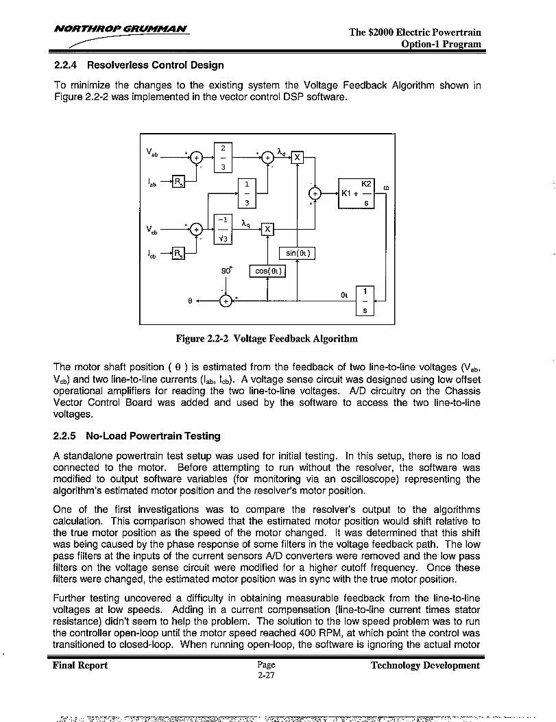
NORTHROP GRUMIN The $2000 Electric PowertrainOption-1 Program
2.2.4 Resolverless Control Design
To minimize the changes to the existing system the Voltage Feedback Algorithm shown inFigure 2.2-2 was implemented in the vector control DSP software.
vab
Iab
vcb
Icb
-++%-’%“d +--=-l
Ykl’-fl I-w -LEE I
Figure 2.2-2 Voltage Feedback Algorithm
The motor shaft position ( e ) is estimated from the feedback of two line-to-line voltages (V,b,Vcb) and two line-to-line currents (lab, Icb). A voltage sense circuit was designed using low offsetoperational amplifiers for reading the two line-to-line voltages. A/D circuitry on the ChassisVector Control Board was added and used by the software to access the two line-to-linevoltages.
2.2.5 No-Load Powertrain Testing
A standalone powertrain test setup was used for initial testing. In this setup, there is no loadconnected to the motor. Before attempting to run without the resolver, the software wasmodified to output software variables (for monitoring via an oscilloscope) representing thealgorithm’s estimated motor position and the resolver’s motor position.
One of the first investigations was to compare the resolver’s output to the algorithmscalculation. This comparison showed that the estimated motor position would shift relative tothe true motor position as the speed of the motor changed. It was determined that this shiftwas being caused by the phase response of some filters in the voltage feedback path. The lowpass filters at the inputs of the current sensors A/D converters were removed and the low passfilters on the voltage sense circuit were modified for a higher cutoff frequency. Once thesefilters were changed, the estimated motor position was in sync with the true motor position.
Further testing uncovered a difficulty in obtaining measurable feedback from the line-to-linevoltages at low speeds. Adding in a current compensation (line-to-line current times statorresistance) didn’t seem to help the problem. The solution to the low speed problem was to runthe controller open-loop until the motor speed reached 400 RPM, at which point the control wastransitioned to closed-loop. When running open-loop, the software is ignoring the actual motor
Final Report Page Technolog Development2-27
.—
NORTHROP GRUM-N The $2000 Electric PowertrainOption-1 Program
speed and using a set speed of 400 RPM. To operate in the open-loop region, the flux as afunction of torque command had to be increased.
2.2.6 Powertrain Testing with Back-to-Back Dynamometer Fixture
The resolverless control test system was setup on one of our back-to-back test fixtures. Theback-to-back test fixture uses a production EV powertrain to provide a programmable load forthe powertrain being tested.
When tested under load, the estimated motor position would shift relative to the true motorposition (similar to the phenomenon addressed during no-load testing). The amount of shift inthe estimated motor position seemed to be a function of the amount of load or current draw. Atorque command factor was included in the position estimator code to account for this shift. Formoderate loads (less than half of maximum torque), the control scheme worked well. For largerloads (greater than ?4 of maximum torque), the estimated motor position would shift enough tocause an over current condition that could potentially damage the system.
Two major issues arose from testing. The first issue is the limited amount of torque availablewhile operating in the open-loop region. Under heavily loaded conditions, the amount of timerequired to reach 400 rpm was unacceptable. The other issue is the lack of smooth torquecontrol during the transition from open-loop to closed-loop control. Once the transition wasmade to closed-loop control, the motor speed would increase at a much faster rate for the sametorque command.
2.2.7 Conclusion
Due to the lack of smooth torque control during the transition from open-loop to closed-loopcontrol, this method of resolverless control is not applicable for electric vehicles. However, thiscontrol method may be appropriate for other applications such as flywheels, generators, fans,or pumps.
Final Report Page Technology Development2-28
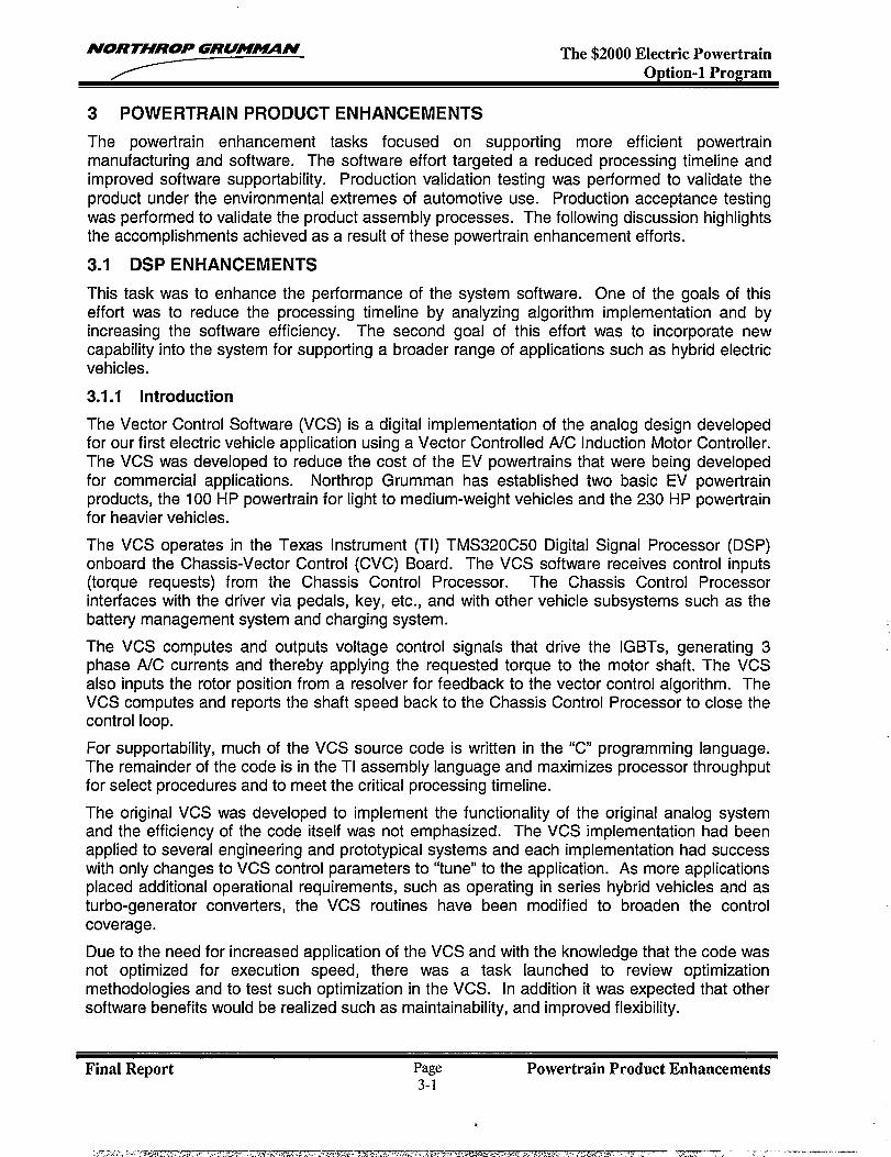
NORTHROP GRUM~N The $2000 Electric PowertrainODtion-1 ProQram
3 POWERTRAIN PRODUCT ENHANCEMENTS
The powertrain enhancement tasks focused on supporting more efficient powertrainmanufacturing and software. The software effort targeted a reduced processing timeline andimproved software supportability. Production validation testing was performed to validate theproduct under the environmental extremes of automotive use. Production acceptance testingwas performed to validate the product assembly processes. The following discussion highlightsthe accomplishments achieved as a result of these powertrain enhancement efforts.
3.1 DSP ENHANCEMENTS
This task was to enhance the performance of the system software. One of the goals of thiseffort was to reduce the processing timeline by analyzing algorithm implementation and byincreasing the software efficiency. The second goal of this effort was to incorporate newcapability into the system for supporting a broader range of applications such as hybrid electricvehicles.
3.1.1 Introduction
The Vector Control Software (VCS) is a digital implementation of the analog design developedfor our first electric vehicle application using a Vector Controlled A/C Induction Motor Controller.The VCS was developed to reduce the cost of the EV powertrains that were being developedfor commercial applications. Northrop Grumman has established two basic EV powertrainproducts, the 100 HP powertrain for light to medium-weight vehicles and the 230 HP powertrainfor heavier vehicles.
The VCS operates in the Texas Instrument (Tl) TMS320C50 Digital Signal Processor (DSP)onboard the Chassis-Vector Control (CVC) Board. The VCS software receives control inputs(torque requests) from the Chassis Control Processor. The Chassis Control Processorinterfaces with the driver via pedals, key, etc., and with other vehicle subsystems such as thebattery management system and charging system.
The VCS computes and outputs voltage control signals that drive the IGBTs, generating 3phase A/C currents and thereby applying the requested torque to the motor shaft. The VCSalso inputs the rotor position from a resolver for feedback to the vector control algorithm. TheVCS computes and reports the shaft speed back to the Chassis Control Processor to close thecontrol loop.
For supportability, much of the VCS source code is written in the “C programming language.The remainder of the code is in the TI assembly language and maximizes processor throughputfor select procedures and to meet the critical processing timeline.
The original VCS was developed to implement the functionality of the original analog systemand the efficiency of the code itself was not emphasized. The VCS implementation had beenapplied to several engineering and prototypical systems and each implementation had successwith only changes to VCS control parameters to “tune” to the application. As more applicationsplaced additional operational requirements, such as operating in series hybrid vehicles and asturbo-generator converters, the VCS routines have been modified to broaden the controlcoverage.
Due to the need for increased application of the VCS and with the knowledge that the code wasnot optimized for execution speed, there was a task launched to review optimizationmethodologies and to test such optimization in the VCS. In addition it was expected that othersoftware benefits would be realized such as maintainability, and improved flexibility.
Final Report Page Powertrain Product Enhancements3-1
, -1
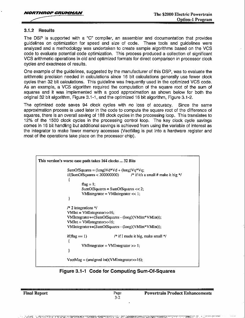
NORTHROP GRUM~N The $2000 Electric PowertrainOption-1 Program
3.1.2 Results
The DSP is supported with a “C’ compiler, an assembler and documentation that providesguidelines on optimization for speed and size of code. These tools and guidelines wereanalyzed and a methodology was undertaken to create sample algorithms based on the VCScode to evaluate potential code optimization. This process produced a collection of significantVCS arithmetic operations in old and optimized formats for direct comparison in processor clockcycles and exactness of results.
One example of the guidelines, suggested by the manufacturer of this DSP, was to evaluate thearithmetic precision needed in calculations since 16 bit calculations generally use fewer clockcycles than 32 bit calculations. This guideline was frequently used in the optimized VCS code.As an example, a VCS algorithm required the computation of the square root of the sum ofsquares and it was implemented with a good approximation as shown below for both theoriginal 32 bit algorithm, Figure 3.1-1, and the optimized 16 bit algorithm, Figure 3.1-2.
The optimized code saves 94 clock cycles with no loss of accuracy. Since the sameapproximation process is used later in the code to compute the square root of the difference ofsquares, there is an overall saving of 188 clock cycles in the processing loop. This translates to12% of the 1500 clock cycles in the processing control loop. The key clock cycle savingscomes in 16 bit handling but additional savings is achieved from using the variable of interest asthe integrator to make fewer memory accesses (VectMag is put into a hardware register andmost of the operations take place on the processor chip).
This version’s worse case path takes 164 clocks ...32 Bits
SumOfSquares = (long)Vd*Vd + (long)Vq*Vq;if(SumOfSquares c 200000000) /* if it’s a small # make it big */
{flag=l;SumOfSquares = SumOfSquares cc 2;VMIntegrator = VMIntegrator cc 1;
}
I* 2 integrations *IVMInt = VMIntegrato~>16;VMIntegrator+=(SumOfSquares - (long) (VMInt*VMInt));VMInt = VMIntegratop>16;VMIntegrator+=(SumOfSquares - (long) (VMInt*VMInt));
if(flag = 1) /*if I made it big, make small*/
{VMIntegrator = VMIntegrator >> 1;
}
VectMag = (unsigned int)(VMIntegrato~> 16);
Figure 3.1-1 Code for Computing Sum-Of-Squares
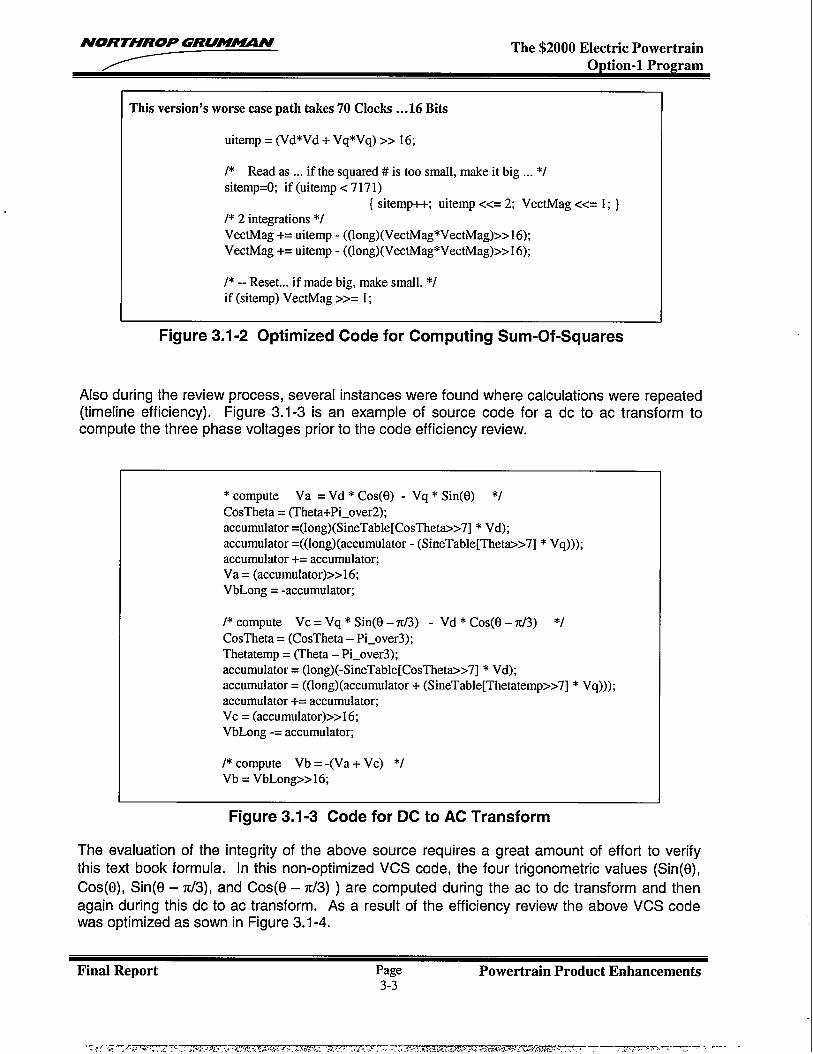
NORTHROP GRU!MN The $2000 Electric PowertrainOption-1 Program
This version’s worse case path takes 70 Clocks . ..16 Bits
uitemp = (Vd*Vd + Vq*Vq) >> 16;
/* Read as ... if the squared # is too small, make it big ... */sitemp=O; if(uitemp<7171)
{ sitemp++; uitemp CC= 2; VectMag <c= 1; ]I* 2 integrations *IVectMag += uitemp - ((long) (VectMag*VectMag)>> 16);VectMag += uitemp - ((long) (VectMag*VectMag)>> 16);
/* -- Reset... if made big, make small. */if (sitemp) VectMag >>= 1;
Figure 3.1-2 Optimized Code for Computing Sum-Of-Squares
Also during the review process, several instances were found where calculations were repeated(timeline efficiency). Figure 3.1-3 is an example of source code for a dc to ac transformcompute the three phase voltages prior to the code efficiency review.
* compute Va = Vd * COS(Q - Vq * Sin(El) */CosTheta = (Theta+Pi_over2);accumulator =(long)(SineTable[ CosThet->7] * Vd);accumulator =((long)(accumulator - (SineTable[Thet~>7] * Vq)));accumulator += accumulator;Va = (accumulator)>> 16;VbLong = -accumulator;
1’ compute Vc = Vq * Sin@ – 7t/3) - Vd * Cos(O– 7c/3) “1CosTheta = (CosTheta – Pi_over3);Thetatemp = (Theta – Pi_over3);accumulator = (long)(-SineTable[CosThet->7] * Vd);accumulator = ((long) (accumulator + (SineTable[Thetatemp>>7] * Vq)));accumulator += accumulator;Vc = (accumulator)>> 16;VbLong -= accumulator;
I* compute Vb = -(Va + Vc) ‘/Vb = VbLong>>16;
to
Figure 3.1-3 Code for DC to AC Transform
The evaluation of the integrity of the above source requires a great amount of effort to verifythis text book formula. In this non-optimized VCS code, the four trigonometric values (Sin(f3),
Cos(0), Sin(O – 7c/3), and Cos(e – n/3) ) are computed during the ac to dc transform and thenagain during this dc to ac transform. As a result of the efficiency review the above VCS codewas optimized as sown in Figure 3.1-4.
Final Report Page Powertrain Product Enhancements3-3
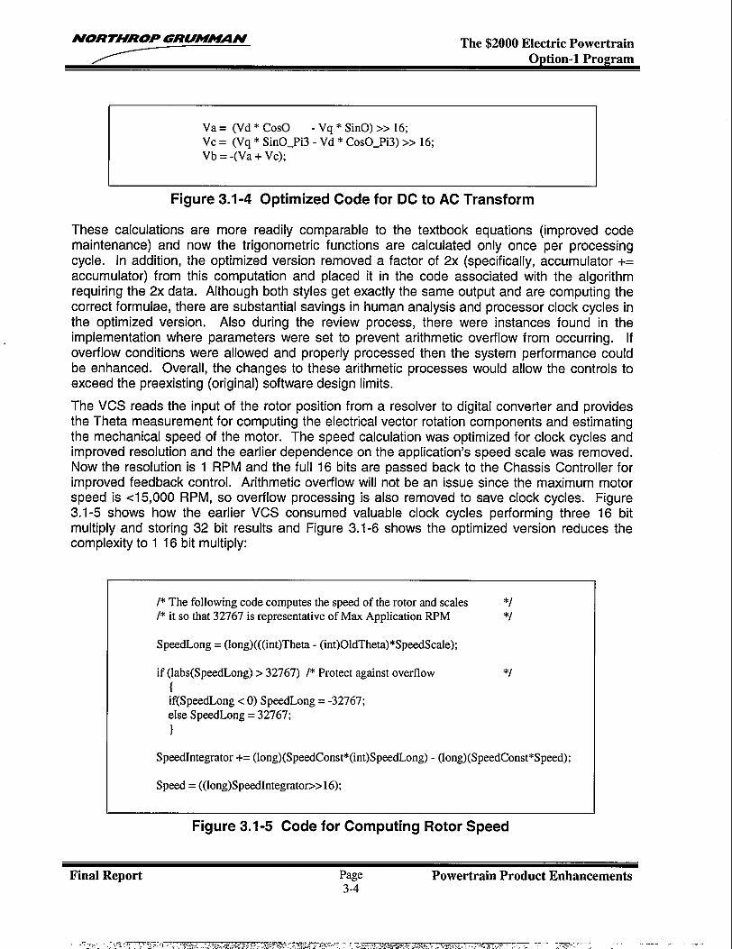
NORTHROP GRUW!!N The $2000 Electric PowertrainOption-1 Program
Va = (Vd * COSO - Vq * SinO) >> 16;Vc = (Vq * SinO_Pi3 - Vd * CosO_Pi3) >> 16;Vb = -(Va + Vc);
Figure 3.1-4 Optimized Code for DC to AC Transform
These calculations are more readily comparable to the textbook equations (improved codemaintenance) and now the trigonometric functions are calculated only once per processingcycle. In addition, the optimized version removed a factor of 2x (specifically, accumulator +=accumulator) from this computation and placed it in the code associated with the algorithmrequiring the 2x data. Although both styles get exactly the same output and are computing thecorrect formulae, there are substantial savings in human analysis and processor clock cycles inthe optimized version. Also during the review process, there were instances found in theimplementation where parameters were set to prevent arithmetic overflow from occurring. Ifoverflow conditions were allowed and properly processed then the system performance couldbe enhanced. Overall, the changes to these arithmetic processes would allow the controls toexceed the preexisting (original) software design limits.
The VCS reads the input of the rotor position from a resolver to digital converter and providesthe Theta measurement for computing the electrical vector rotation components and estimatingthe mechanical speed of the motor. The speed calculation was optimized for clock cycles andimproved resolution and the earlier dependence on the application’s speed scale was removed.Now the resolution is 1 RPM and the full 16 bits are passed back to the Chassis Controller forimproved feedback control. Arithmetic overflow will not be an issue since the maximum motorspeed is cl 5,000 RPM, so overflow processing is also removed to save clock cycles. Figure3,1-5 shows how the earlier VCS consumed valuable clock cycles performing three 16 bitmultiply and storing 32 bit results and Figure 3.1-6 shows the optimized version reduces thecomplexity to 1 16 bit multiply:
*J
/* The following code computes the speed of the rotor and scales */
/*it so that 32767 is representative of Max Application RPM */
SpeedLong = (long) (((int)Theta - (int)OldTheta)*SpeedScale);
if (labs(SpeedLong) > 32767) /* Protect against overflow{if(SpeedLong c O)SpeedLong = -32767;else SpeedLong = 32767;
}
SpeedIntegrator += (long) (SpeedConst*(int)SpeedLong) - (long)(SpeedConst*Speed);
Speed = ((long)SpeedIntegrato~> 16);
Figure 3.1-5 Code for Computing Rotor Speed
Final Report Page Powertrain Product Enhancements3-4
-.
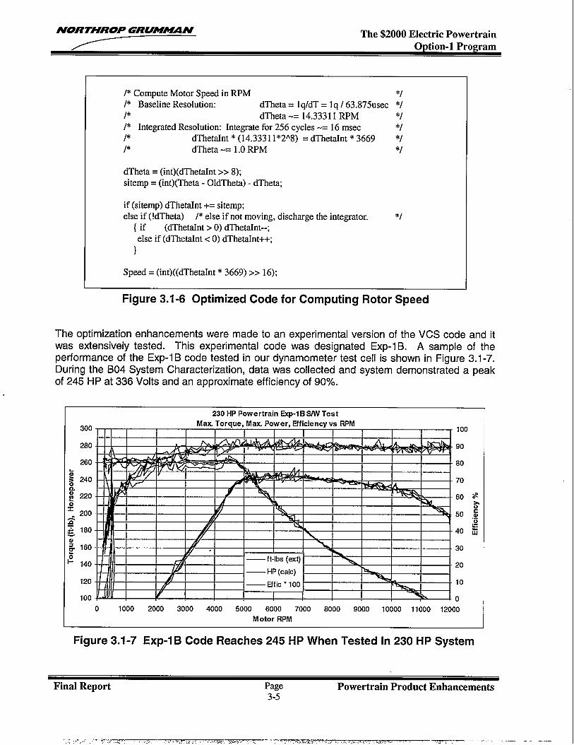
NORTHROP GRUM~ff The $2000 Electric PowertrainOption-1 Program
/* Compute Motor Speed in RPM *J
/* Baseline Resolution: dTheta = lq/dT = lq / 63.875usec *//* dTheta -= 14.33311 RPM *I
/* Integrated Resolution: Integrate for 256 cycles -= 16 msec */J* dThetaInt * (14.333 11*2A8) = dThetaInt * 3669 */J* dTheta -= 1.0 RPM *J
dTheta = (int)(dThetaInt >> 8);sitemp = (int)(Theta - OldTheta) - dTheta;
if (sitemp) dThetaInt += sitemp;else if (!dTheta) /* else if not moving, discharge the integrator. */
{ if (dThetaInt > O)dThetaInt--;else if (dThetrdnt c O)dThetaInt++;
}
Speed = (int)((dThetaInt * 3669) >> 16);
Figure 3.1-6 Optimized Code for Computing Rotor Speed
The optimization enhancements were made to an experimental version of the VCS code and itwas extensively tested. This experimental code was designated Exp-1 B. A sample of theperformance of the Exp-1 B code tested in our dynamometer test cell is shown in Figure 3.1-7.During the B04 System Characterization, data was collected and system demonstrated a peakof 245 HP at 336 Volts and an approximate efficiency of 90Y0. -
300
280
280
- 140
120
100
l-l—u.
i-l-w
230 HP Powertrain Exp-1 B SiW Test
Max. Torque, Max. Power, Efficiency vs RPM100
90
80
70
30
20
10
0
0 1000 2000 3000 4000 5000 6000 7000 8000 9000 10000 11000 12000
Motor RPM
Figure 3.1-7 Exp-1 B Code Reaches 245 HP When Tested [n 230 HP System
Final Report Page Powertrain Product Enhancements3-3
..,,-..~,.,-7-:, ., ,:. , ,,.,y----~~~w ,, ., , , ,.,,+,,:A-..,,..,,. .,-— ,. .,>,.. (... .. . . .. ... ...... ...... . ,- —--—- -—
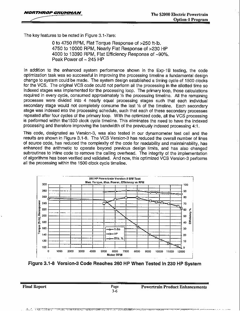
NORTHROP GRU!WUIN The $2000 Electric Powertrain
The key features to be noted in Figure 3.1 -7are:
O to 4750 RPM, Flat Torque Response of >250 ft-lb.4750 to 10000 RPM, Nearly Flat Response of >230 HP4000 to 13390 RPM, Flat Efficiency Response of -90?4.Peak Power of -245 HP
In addition to the enhanced system performance shown in the Exp-1 B testing, the codeoptimization task was so successful in improving the processing timeline a fundamental designchange to system could be made. The system design established a timing cycle of 1500 clocksfor the VCS. The original VCS code could not perform all the processing in the allotted time soindexed stages was implemented for the processing loop. The primary loop, those calculationsrequired in every cycle, consumed approximately % the processing timeiine. All the remainingprocesses were divided into 4 nearly equal processing stages such that each individualsecondary stage would not completely consume the last % of the timeline. Each secondarystage was indexed into the processing schedule, such that each of these secondary processesrepeated after four cycles of the primary loop. With the optimized code, all the VCS processingis performed within thel 500 clock cycle timeline. This eliminates the need to have the indexedprocessing and therefore improving the bandwidth of the previously indexed processing 4:1.
This code, designated as Version-3, was also tested in our dynamometer test cell and theresults are shown in Figure 3.1-8. The VCS Version-3 has reduced the overall number of linesof source code, has reduced the complexity of the code for readability and maintainability, hasenhanced the arithmetic to operate beyond previous design limits, and has also changedsubroutines to inline code to remove the calling overhead. The integrity of the implementationof algorithms has been verified and validated. And now, this optimized VCS Version-3 performsall the processing within the 1500 clock cycle timeline.
300
280
260
230 HPPowertrain Version-3 W TestMex Torque, Msx. Power, Efficiency vs RPM
I I I
—I I I I I 1
A,I I I I
I \l III I I, , , , m 1 I I I 1
1 I I II I I I \ I I I I
I I I I I I x I I I I-50 ~
1
I g
40 gI I I I I I I u I I I
m
S 160- I I I I m I I Is
*ft:bs -30
140- I I I -a- HP I I >= I I -20
120
100
II I I I I
*Efk. %I I I nl I
4 , t # , , , . . 10
I I I I I I I I I I I =L
o0 1000 2000 3000 4000 5000 6000 7000 8000 9000 10000 11000 12000
Motor RPM
Figure 3.1-8 Version-3 Code Reaches 260 HP When Tested [n 230 HP System
Final Report Page Powertrain Product Enhancements3-6
NORTHROP GRUM~N The $2000 Electric PowertrainOption-1 Program
3.1.3 Conclusions
The VCS Version-3 code has been tested to meet the requirements for release into theproduction systems. It is the version of code that is in the current production system. It hassubstantially increased the performance capability of the systems. The 230 HP product hasbeen measured to produce 260 HP and similarly, the 100 HP product has been measured toproduce 120 HP.
The code optimization task far exceeded our expectations. With the unexpected shortening ofthe timeline to the level of having a single processing loop means that all of the controls aretightly coupled and thus the maximum dynamic range can be realized. This, coupled withenhanced arithmetic control, provides the 100 HP and 230 HP Powertrains the processingcapability to perform well above the advertised limits.
In conclusion, the enhanced algorithms implemented in the DSP code now exceeds limit theperformance of the system. For example, the improved horsepower measurement shown inthis report for both the 100 HP and 230 HP products was limited by the battery’s powercapability. The code is now more understandable for software maintenance. Overall, theresults of this software optimization task far exceeded the goals envisioned at the start of theeffort.
Final Report Page Powertrain Product Enhancements3-7

NORTHROP GRUM%UIN The $2000 Electric PowertrainOption-1 Program
3.2 PRODUCTION VALIDATION AND ACCEPTANCE TEST
3.2.1 Test Development Overview
The validation test program was developed through a four-step process. First, the automotive-use environment and failure mechanisms were defined. Second, tests were specified andprocedures written to subject the equipment to all aspects of this environment. In the third step,the order of the tests was defined. The final step was then to compile test results. Thefollowing discussion provides an overview of the TRP activities as well as the test results for theentire design verification and production validation phases of testing.
3.2.2 Definition of the Use Environment
The initial objective in developing the test program was to establish what the product would besubjected to during the course of its useful service life and what stress mechanisms would besusceptible to this environment. Table 3.2-1 provides a list of the tests applicable to theAutomotive ‘(Use” environment, a brief definition of each component, its associated stressmode(s) and test objectives. This list was derived from a number of sources includingourselves, providing power electronics expertise, a major automotive manufacturer providingmany generations of vehicle test experience, and the electronics industry which providedelectronics standards and guidelines.
TablCategory
PerformanceDurability
EnvironmentalDurability
3.2-1 TeslTest Name
Key Cycle
AggravatedHumidity
Power Cycle
ThermalCycle
PWA ThermalShock
Transportationn Vibration
SpecifiecOperating
StatusOperating
Non-Operating
Operating
Operating
Non-Operating
Non-Operating
for Use in the AutolStress Modes Accelerated
Current and VoltageTransients during powercycling
Absorbed Moisture
1) Solder Joint fatigueassociated withdie/wire bonds inpower devices
2) Mechanical interfacebetween powerdevices and coldplate.
1) Solder joint fatigue onPWAS
2) Material compatibility3) Material stress
fracture1) Solder joint integrity2) Stress fracture
Mechanical fatigue, wirechafing, package integrity,material fretting
)tive EnvironmentTest Objective
Simulate vehicle Key-ON andKey-OFF cycles by1) subjecting components to
repeated inrush current andvoltage transients
2) exercising mechanical relays.Expose equipment to repetitivecycles of moisture to revealmoisture induced failures andoperational intermittence causedby condensation atinterconnections.Verify mechanical integrity of1) solder connections internal to
power devices and2) thermal interface material
between power devices andheat sinks.
Verify mechanical integrity of:1) solder joints on all PWAS and2) propagation of stress fractures
in ICs.
Verify mechanical integrity of1) solder joints on all PWAS and2) propagation of stress fractures
in lCs.Verify mechanical integrity ofPowertrain in its shipping containerand shipping container.
Final Report Page Powertrain Product Enhancements3-8
.-.Tr. —,—- 7-.--..-—-
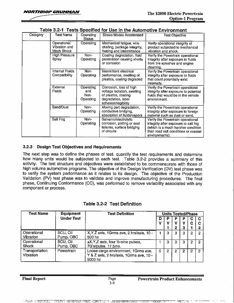
NORTHROP GRUM~N The $2000 Electric PowertrainOption-1 Program
TablCategory
3.2-1 Tests Specified for Use in the AutonTest Name Orreratinq Stress Modes Accelerated
Spray Operating penetration-causing shortsor corrosion
Internal Fluids Non- Intermittent electricalCompatibility Operating performance, swelling of
plastics, coating degraded
Corrosion, loss of highvoltage isolation, swellingof plastics, coatingdegradation, label
I adhesion/legibilitySand/Dust Non- I Moving part degradation,
Salt Fog
Operating
Non-Operating
conductive bridging,absorption of fluids/vaporsGalvanic/electrolyticcorrosion, potting or sealfailures, surface bridgingof circuits
otive EnvironmentTest Objective
Verify operational integrity ofproduct subjected to mechanicalvibration and shock.Verify the Powertrain operationalintegrity after exposure to fluidsfrom tire splashes and enginecleaning.Verify the Powertrain operationalintegrity after exposure to fluidsthat could potentially existinternally.Verify the Powertrain operationalintegrity after exposure to potentialfluids that would be in the vehicleenvironment.
Verify the Powertrain operationalintegrity after exposure to foreignmaterial such as dust or sand.Verifv the Powertrain operational
&integfity after exposure’ to salt fog(which is a much harsher conditionthan road salt conditions or coastal
1.2.3 Design Test Objectives and Requirements
The next step was to define the phases of test, quantify the test requirements and determinehow many units would be subjected to each test. Table 3.2-2 provides a summary of thisactivity. The test structure and objectives were established to be commensurate with those ofhigh volume automotive programs. The objective of the Design Verification (DV) test phase wasto verify the system performance as it relates to its design. The objective of the ProductionValidation (PV) test phase was to validate and improvephase, Continuing Conformance (CC), was performed tocomponent or process.
manufacturing procedures. The finalremove variability associated with any
Table 3.2-2 Test Definition
Test Name Equipment Test Definition Units Tested/PhaseUnder Test D P P P c c
v v v v c. c1 2 3 1 2
Operational SCU, Oil X,Y,Z axis, 1Grins ave, 2 hrslaxis, 10- 1 3 3 3 2 2Vibration Pump, OBC 500 hzOperational SCU, Oil &,Y,Z axis, four ‘/2-sine pulses, 1 3 3 3 2 2Shock Pump, OBC 7G’s/pulse, 17.5ms.Transportation Powertrain Loose cargo environment, 1Grins ave. o 2 2 2 2 2Vibration Y & Z axis, 2 hrs/axis, 1Grins ave, 10-
5000 hz
Final Report Page Powertrain Product Enhancements3-9

NORTHROP GRUM~N The $2000 Electric Powertrain—
Table 3.2-2 Test Definition
Test Name Equipment Test Definition Units Tested/PhaseUnder Test D P P P c c
v v v v c c1 2 3 1 2
EM1/EMC, Powertrain Internal Specification 1 1 1 1 0 0Voltage & LoadTransientPWA Thermal All PWAS 24 shock cycles: o 3 3 3 0 0Shock 19-0Cto60C
2- -20C to 70C1- -40C to 85C
Thermal Powertrain -40C, 56 hp, 31 OVDC, 50ADC, 8000 2 2 2 2 2 2Extremes RPM, 1 hr
+59C, 56hp, 31OVDC, 50ADC, 8000RPM, 1 hr
Key Cycle Powertrain 22,400 CYCk3S, i’ yr life, WY. o 2 2 2 2 2Durability confidencePower Cycle Powertrain 1960 Cycles, AT(IGBT Junction Temp) o 2 2 2 2 2Durability = 128°CThermal Cycle Powertrain 148 cycles, Solder Joints -25°C to o 2 2 2 2 2Durability +85°CHigh Pressure Powertrain 80-100 psi, 46°C o 3 3 3 0 0Water/SteamFluids Powertrain Non-operating: o 2 2 2 0 0Compatibility Resistance to Turbo Oil in (SCU), High
Pressure Steam, washer fluid, ATF,brake fluid, degreaserOperating:Salt Splash
Exposure to Dust Powertrain 5 hrs, 50 micron particle, non-powered o 1 1 1 0 0Salt Fog Powertrain 240 hr, 5% solution, 35C, non- 0 3 3 3 0 0
operating
3.2.4 Test Execution
The flow diagram, shown in Figure 3.2-1, illustrates the order in which the major tests wereperformed during Production Validation test. Note that tests were executed in a series-parallelfashion to facilitate timely completion. Each block of tests were preceded and followed by asystem level Acceptance test (PT Accept) to verify successful completion. The tests areperformed in series and were selected based upon the stress modes.
Final Report Page Powertrain Product Enhancements3-1o
I!WX7WWZT’ZSW-7777-”’Z’;.W-=-’-F7 ~~.~7m.KxmmTcwL),> . . . . .. . ,.m’vr,>... ,.. ., .,. . . . ..T--——-.—., -:-:.,
.-. . ..+-. I
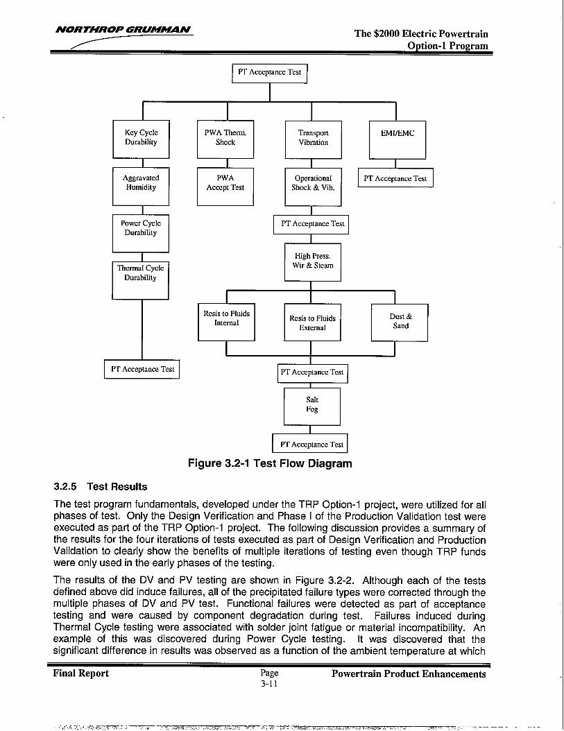
NORTHROP GRUMmN The $2000 Electric Powertrain
1
I I I
DAggravated
Humidity
aPower CycleDurability
TThermaI Cycle
Durability
/-PT Acceptance Test
I‘C:%cstI , Iiy.l, ,nAccePtanceTet
PT Acceptance Test
mHigh Press..tr & Steam
n I II I I I 1 I
Resis to FluidsInternal
Resis to Fhrids Dust &
External Sand
EPT Acceptance Test
saltFog
PT Acceptance Test
Figure 3.2-1 Test Flow Diagram
3.2.5 Test Results
The test program fundamentals, developed under the TRP Option-1 proiect, were utilized for allphases of test. Only the Design Verification and Phase I of the Produc~on “Validation test wereexecuted as part of the TRP Option-1 project. The following discussion provides a summary ofthe results for the four iterations of tests executed as part of Design Verification and ProductionValidation to clearly show the benefits of multiple iterations of testing even though TRP fundswere only used in the early phases of the testing.
The results of the DV and PV testing are shown in Figure 3.2-2. Although each of the testsdefined above did induce failures, all of the precipitated failure types were corrected through themultiple phases of DV and PV test. Functional failures were detected as part of acceptancetesting and were caused by component degradation during test. Failures induced duringThermal Cycle testing were associated with solder joint fatigue or material incompatibility. Anexample of this was discovered during Power Cycle testing. [t was discovered that thesignificant difference in results was observed as a function of the ambient temperature at which
Final Report Page Powertrain Product Enhancements3-11
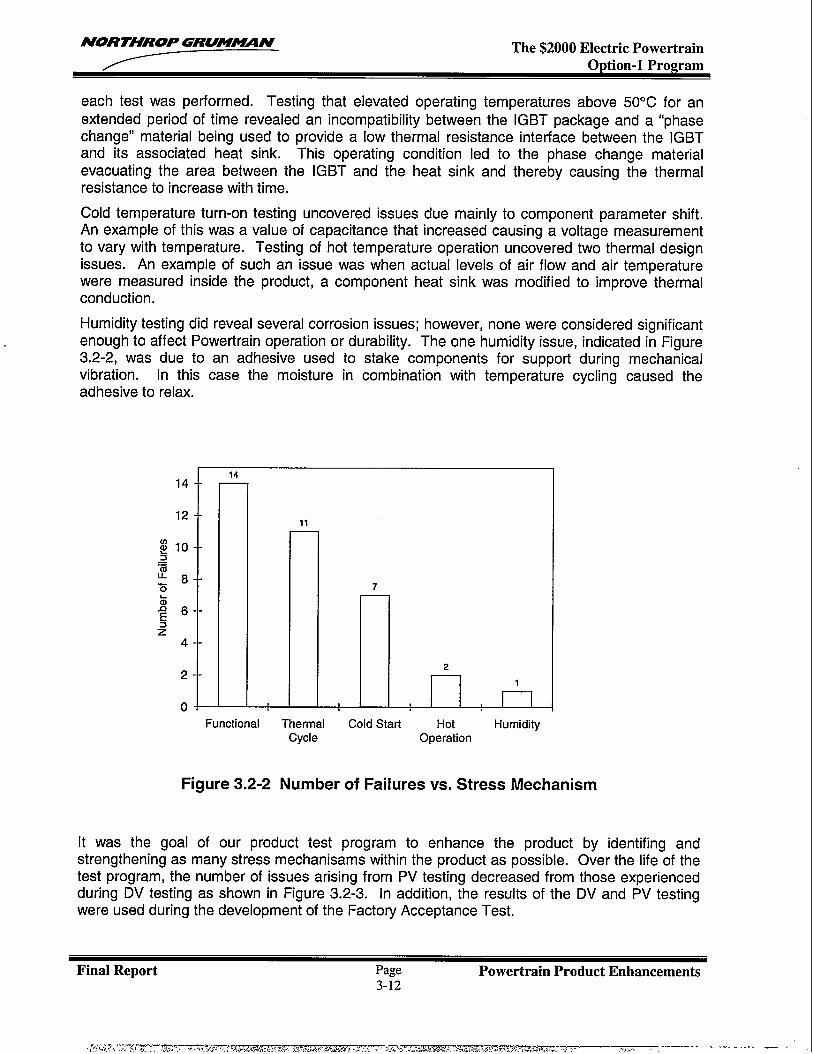
NORTHROP GRUM~N The $2000 Electric PowertrainOption-1 Program
each test was performed. Testing that elevated operating temperatures above 50”C for anextended period of time revealed an incompatibility between the IGBT package and a “phasechange” material being used to provide a low thermal resistance interface between the IGBTand its associated heat sink. This operating condition led to the phase change materialevacuating the area between the IGBT and the heat sink and thereby causing the thermalresistance to increase with time.
Cold temperature turn-on testing uncovered issues due mainly to component parameter shift.An example of this was a value of capacitance that increased causing a voltage measurementto vary with temperature. Testing of hot temperature operation uncovered two thermal designissues. An example of such an issue was when actual levels of air flow and air temperaturewere measured inside the product, a component heat sink was modified to improve thermalconduction.
Humidity testing did reveal several corrosion issues; however, none were considered significantenough to affect Powertrain operation or durability. The one humidity issue, indicated in Figure3.2-2, was due to an adhesive used to stake components for support during mechanicalvibration. In this case the moisture in combination with temperature cycling caused theadhesive to relax.
—
—
—
11—
7—
Jl_!_fLFunctional Thermal Cold Start Hot Humiditv
Cycle Operation
Figure 3.2-2 Number of Failures vs. Stress Mechanism
It was the goal of our product test program to enhance the product by identifying andstrengthening as many stress mechanisms within the product as possible. Over the life of thetest program, the number of issues arising from PV testing decreased from those experiencedduring DV testing as shown in Figure 3.2-3. In addition, the results of the DV and PV testingwere used during the development of the Factory Acceptance Test.
Final Report Page Powertrain Product Enhancements3-12
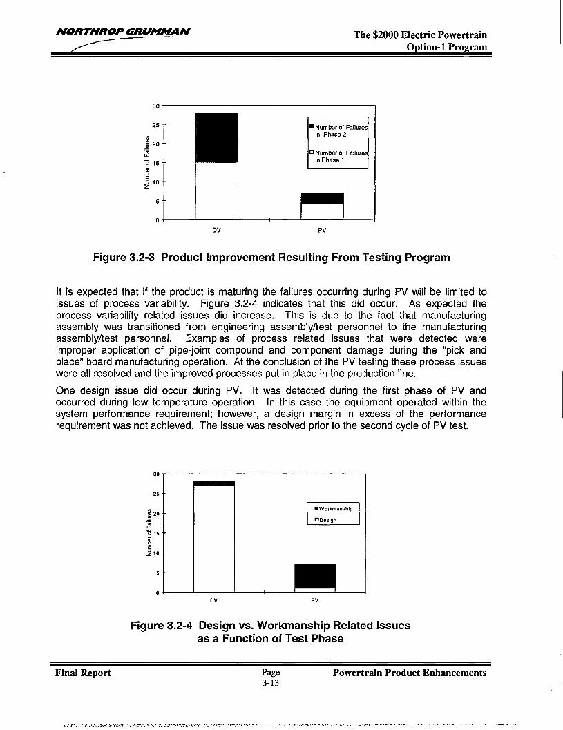
NORTHROP GRUWWUN The $2000 Electric PowertrainOption-1 Program
30
25- -
El
❑ N“~ber of Failurein Phase 2
%520- -.If ❑Nufnberof Failure
z15- - in Phase 1
&
:1o- -z
5- -
0.
DV Pv
Figure 3.2-3 Product Improvement Resulting From Testing Program
It is expected that if the product is maturing the failures occurring during PV will be limited toissues of process variability. Figure 3.2-4 indicates that this did occur. As expected theprocess variability related issues did increase. This is due to the fact that manufacturingassembly was transitioned from engineering assembly/test personnel to the manufacturingassembly/test personnel. Examples of process related issues that were detected wereimproper application of pipe-joint compound and component damage during the “pick andplace” board manufacturing operation. At the conclusion of the PV testing these process issueswere all resolved and the improved processes put in place in the production line.
One design issue did occur during PV. [t was detected during the first phase of PV andoccurred during low temperature operation. In this case the equipment operated within thesystem performance requirement; however, a design margin in excess of the performancerequirement was not achieved. The issue was resolved prior to the second cycle of PV test.
30-
25- -
F==lz 15 +1 I
5- -
01I
DV Pv
Figure 3.2-4 Design vs. Workmanship Related Issuesas a Function of Test Phase
Final Report Page Powertrain Product Enhancements3-13
,,,.-#-----. v-.-m.--:- ., ..- . . .. .J ,A., . ... . . . .- -J’ --—-—. . . . . . . . . .
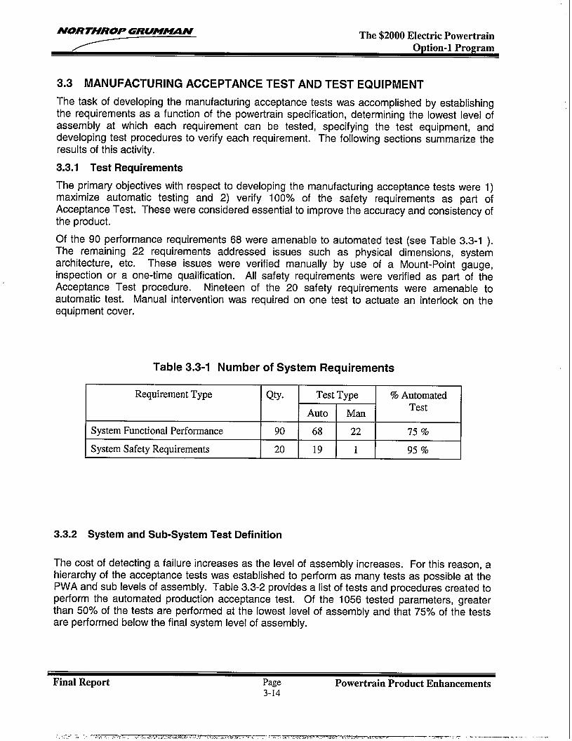
NORTHROP GUUM-N The $2000 Electric PowertrainOption-1 Program
3.3 MANUFACTURING ACCEPTANCE TEST AND TEST EQUIPMENT
The task of developing the manufacturing acceptance tests was accomplished by establishingthe requirements as a function of the powertrain specification, determining the lowest level ofassembly at which each requirement can be tested, specifying the test equipment, anddeveloping test procedures to verify each requirement. The followinq sections summarize theresults of this activity.
3.3.1 Test Requirements
The primary objectives with respect tomaximize automatic testing and 2)
developing the manufacturing acceptance tests were 1)verifv 100’XO of the safetv requirements as part of
Acceptance Test. These w{re considered e~sential to improve the >ccu~acy and consistency ofthe product.
Of the 90 performance requirements 68 were amenable to automated test (see Table 3.3-1 ).The remaining 22 requirements addressed issues such as physical dimensions, systemarchitecture, etc. These issues were verified manually by use of a Mount-Point gauge,inspection or a one-time qualification. All safety requirements were verified as part of theAcceptance Test procedure. Nineteen of the 20 safety requirements were amenable toautomatic test. Manual intervention was required on one test to actuate an interlock on theequipment cover.
Table 3.3-1 Number of System Requirements
RequirementType QtY. Test Type % Automated
Auto ManTest
SystemFunctionalPerformance 90 68 22 75 %
SystemSafety Requirements 20 19 1 95 %
3.3.2 System and Sub-System Test Definition
The cost of detecting a failure increases as the level of assembly increases. For this reason, ahierarchy of the acceptance tests was established to perform as many tests as possible at thePWA and sub levels of assembly. Table 3.3-2 provides a list of tests and procedures created toperform the automated production acceptance test. Of the 1056 tested parameters, greaterthan 50% of the tests are performed at the lowest level of assembly and that 75% of the testsare performed below the final system level of assembly.
I
Final Report Page Powertrain Product Enhancements3-14
; .,.7 -... .! - ,T,7.m..,. .. ......>.>. . ...-.A*>”..--. , .,-, .,,’4,<,’,., 7-7Y->. .-..... .. ....+.. ..-. ,., .— .__. ,.— .=, --—— . . .. ... .
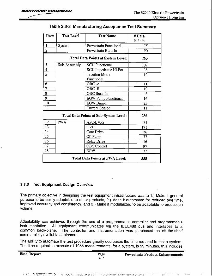
NORTHROP GRUMWMN The $2000 Electric PowertrainOption-1 Program
Table 3.3-2 Manufacturing Acceptance Test Summary
I Item I Test Level Test Name #Data IPoints
1 System Powertrain Functional 1752 Powertrain Bum-In 90
Total Data Points at System Level: 265
3 Sub-Assembly SCU Functional 1094 SCU ImpedanceHi-Pot 385 Traction Motor 10
FunctionalOBC -A 11OBC -B 1(-I+
6
7
11 I Current Sensor 11I
Total Data Points at Sub-System Level: 236 I12 PWA APCILVPS 8113 Cvc 17114 Gate Drive 3615 Oil Pump 7716 Relay Drive 1617 OBC Control 9718 EGW 77
I Total Data Points at PWA Level: 555 I
3.3.3 Test Equipment Design Overview,
The primary objective in designing the test equipment infrastructure was to 1.) Make it generalpurpose to be easily adaptable to other products, 2.) Make it automated for reduced test time,improved accuracy and consistency, and 3.) Make it modularized to be adaptable to productionvolume.
Adaptability was achieved through the use of ainstrumentation. All equipment communicates
programmable controller and programmablevia the IEEE488 bus and interfaces to a
common back-plane. The controller and instrumentation was purchased as off-the-shelfcommercially available equipment.
The ability to automate the test procedure greatly decreases the time required to test a system.The time required to execute all 1056 measurements, for a system, is 99 minutes, this includes
Final Report Page Powertrain Product Enhancements3-15
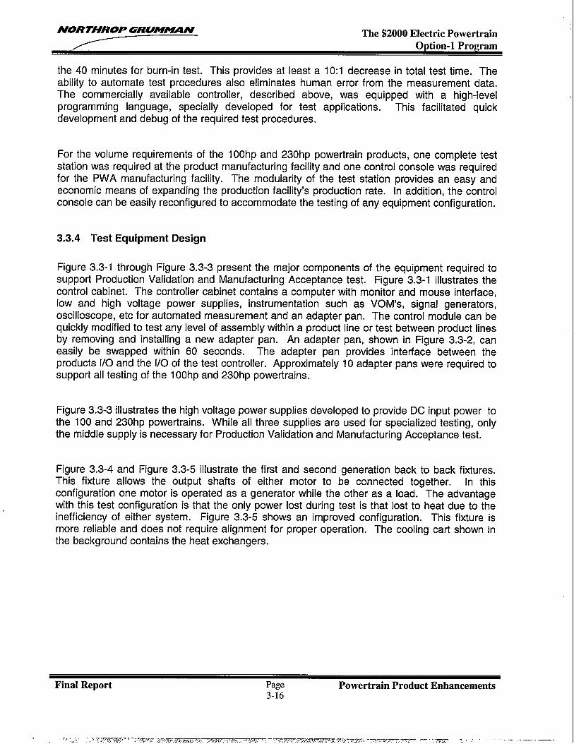
NORTHROP GRUM~N The $2000 Electric Powertrain
the 40 minutes for burn-in test. This provides at least a 10:1 decrease in total test time. Theability to automate test procedures also eliminates human error from the measurement data.The commercially available controller, described above, was equipped with a high-levelprogramming language, specially developed for test applications. This facilitated quickdevelopment and debug of the required test procedures.
For the volume requirements of the 10Ohp and 230hp powertrain products, one complete teststation was required at the product manufacturing facility and one control console was requiredfor the PWA manufacturing facility. The modularity of the test station provides an easy andeconomic means of expanding the production facility’s production rate. In addition, the controlconsole can be easily reconfigured to accommodate the testing of any equipment configuration.
3.3.4 Test Equipment Design
Figure 3.3-1 through Figure 3.3-3 present the major components of the equipment required tosupport Production Validation and Manufacturing Acceptance test. Figure 3.3-1 illustrates thecontrol cabinet. The controller cabinet contains a computer with monitor and mouse interface,low and high voltage power supplies, instrumentation such as VOM’S, signal generators,oscilloscope, etc for automated measurement and an adapter pan. The control module can bequickly modified to test any level of assembly within a product line or test between product linesby removing and installing a new adapter pan. An adapter pan, shown in Figure 3.3-2, caneasily be swapped within 60 seconds. The adapter pan provides interface between theproducts 1/0 and the l/O of the test controller. Approximately 10 adapter pans were required tosupport all testing of the 100hp and 230hp powertrains.
Figure 3.3-3 illustrates the high voltage power supplies developed to provide DC input power tothe 100 and 230hp powertrains. While all three supplies are used for specialized testing, onlythe middle supply is necessary for Production Validation and Manufacturing Acceptance test.
Figure 3.3-4 and Figure 3.3-5 illustrate the first and second generation back to back fixtures.This fixture allows the output shafts of either motor to be connected together. In thisconfiguration one motor is operated as a generator while the other as a load. The advantagewith this test configuration is that the only power lost during test is that lost to heat due to theinefficiency of either system. Figure 3.3-5 shows an improved configuration. This fixture ismore reliable and does not require alignment for proper operation. The cooling cart shown inthe background contains the heat exchangers.
Final Report Page Powertrain Product Enhancements3-16
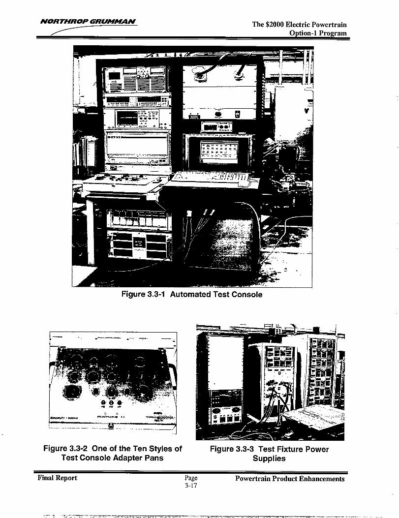
NORTHROP GRUM#UIN The $2000 Electric PowertrainOption-1 Program
Figure 3.3-1 Automated Test Console
~ .*, .~-:—l- rms’r”luq ,. .9+w#+&_:
. . .. ...— .— ._ ..._ —. 3Figure 3.3-2 One of the Ten Styles of
Test Console Adapter PansFigure 3.3-3 Test Fixture Power
Supplies
Final Report Page Powertrain Product Enhancements3-17
,.-.T .,Z.,,T- ., ,., ., . . . . . . . . . . . . . . . .. . . . . . . . . . .. . . . . .. ----- .-,....- -- .,----- . . . . . . . .
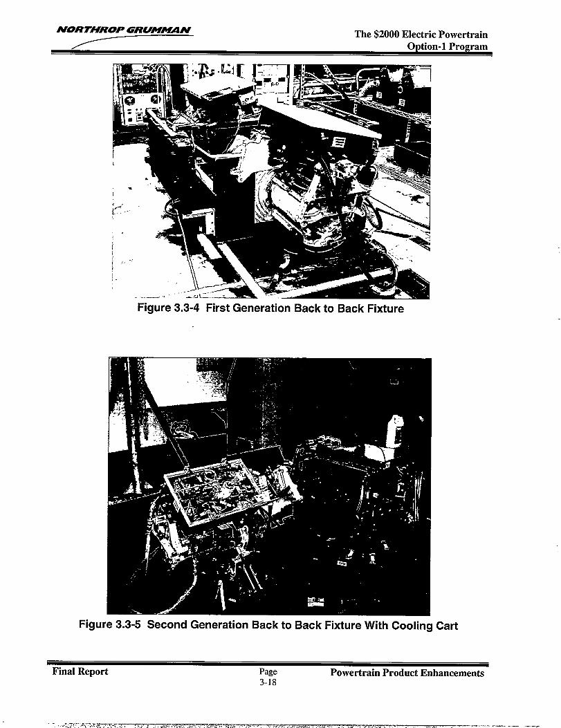
NOR THROP GRUMUN The $2000 Electric PowertrainOption-1 Program
Figure 3.3-4 First Generation Back to Back Fixture
:, —-. -.. .. .. .
Figure 3.3-5 Second Generation Back to Back Fixture With Cooling Cart
Final Report Page Powertrain Product Enhancements3-18
NORTHROP GRUM~N The $2000 Electric PowertrainOption-1 Program
3.4 MANUFACTURING PROCESS DEVELOPMENT
3.4.1 Manufacturing Process Objectives
The objective of this effort was to refine and enhance the manufacturing process for the electricpowertrain. Included in this effort is the development of assembly flow, work instructions, and aprocess analysis.
3.4.2 Manufacturing Process Development Overview
The manufacturing capability for the powertrain product was developed in a three-step process.First, a build plan for the product was created. This defined the product structure, the flow ofequipment in the manufacturing facility and the requirements for assembly work instructions.The next step was to analyze the product flow and the work instruction requirements to findprocesses that could be improved. The final step was to update the work instructions basedupon the results of the analysis and feedback from preliminary assembly trials. This processprovided a detailed layout for the manufacturing facility as well as concise instructions forassembly.
The product structure serves as the primary input to the manufacturing plan. With thisinformation an assembly flow diagram is created. It is then mapped into the manufacturingfacility. The details of the assembly flow diagram include 1) control stations, 2) operator andtooling requirements, 3) test and inspection station requirements, and 4) essential equipmentracks and storage facilities.
Work instructions direct the assembly technician in all aspects of assembly. They providewritten and graphic instructions to the assembly technicians and inform supervisory personnelof skill level requirements. The work orders specify the order in which the instructions are to beperformed. The work instructions and work orders are further refined by the results of theprocess analysis.
The process analysis is a standard industry tool used to review the manufacturing plan againstthe work instructions. The objective of the analysis is to identify issues associated with productflow, instruction and training. For each issue considered, the analysis identifies the potentialcause, effect, method of detection and the risk associated with not detecting an issue. Theanalysis provides feedback on the process implementation such as establishing qualityinspection points within the assembly line.
3.4.3 Manufacturing Plan
A four-step process was used to develop the manufacturing plan for each major assemblywithin the product structure. The first step was to develop a process flow diagram for eachmajor assembly. The example shown in Figure 3.4-1 is for the SCU. The Process Flowdiagram identifies the subassemblies within the SCU and the order in which they were to beassembled. As the assembly continues, subassemblies were moved between staging areas.This indicates a movement from one working area or table to another. This movement is
proceeded by a physical inspection or test to verify configuration control.
The manufacturing facility layout is derived from the process flow diagrams. Figure 3.4-2illustrates a completed facility drawing for the SCU assembly area. This drawing includes work-station locations, required storage areas, and test equipment locations. The figure alsoincludes an area designated for the expediters. These are the manufacturing personnelresponsible for documentation and moving subassemblies between staging areas.
Final Report Page Powertrain Product Enhancements3-19
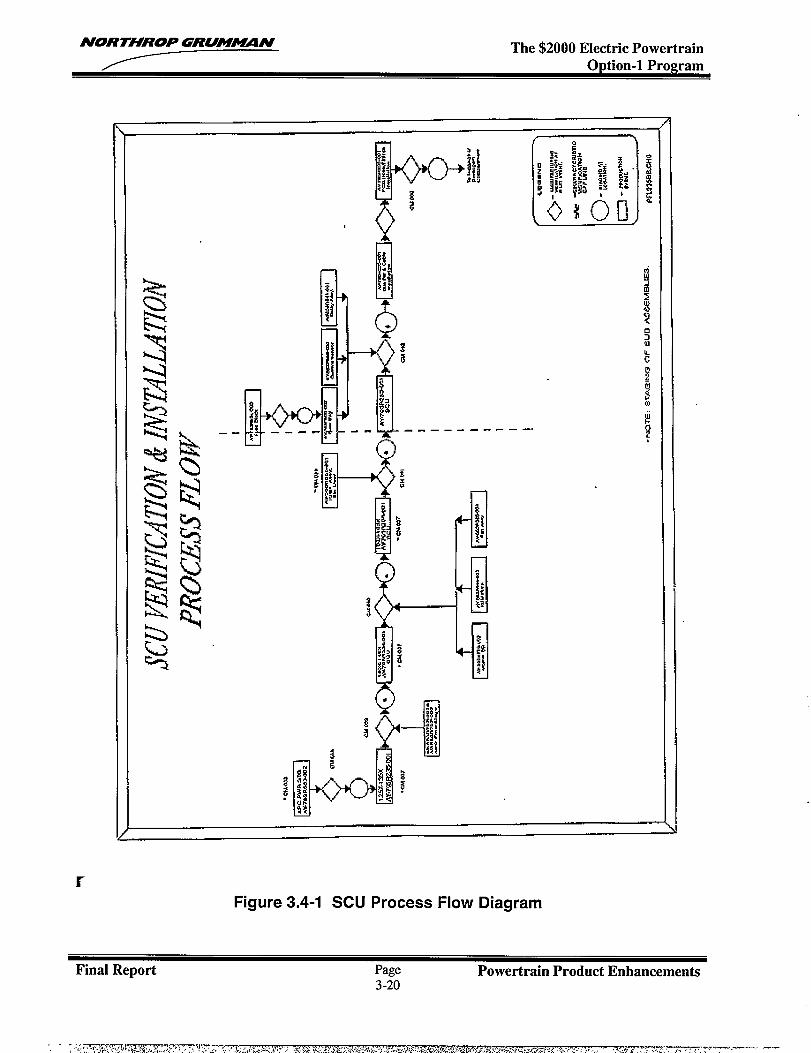
NORTHROP GRUMMN The $2000 Electric PowertrainOption-1 Program
—. .—
x
Figure 3.4-1 SCU Process Flow Diagram
Final Report Page Powertrain Product Enhancements3-20
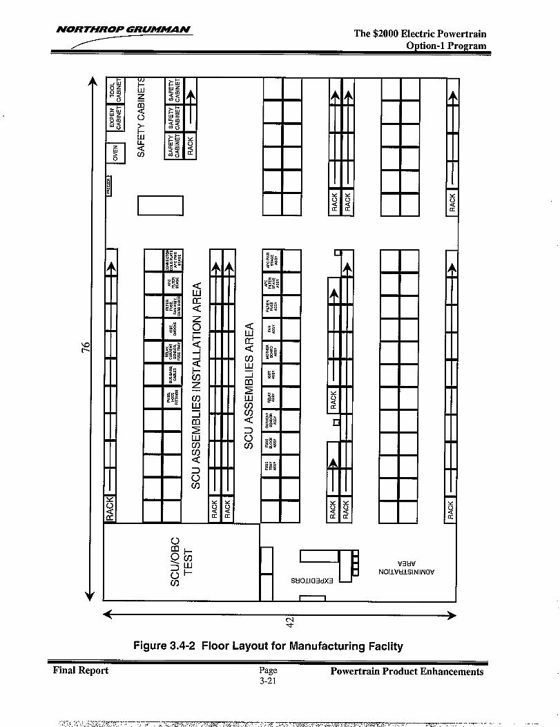
NORTHROP GRUM~N The $2000 Electric PowertrainOption-1 Program
m
[
l—
WltlvNOIIVE!lSINI WCiV
+
Figure 3.4-2 Floor Layout for Manufacturing Faclity
Final Report Page Powertrain Product Enhancements3-21
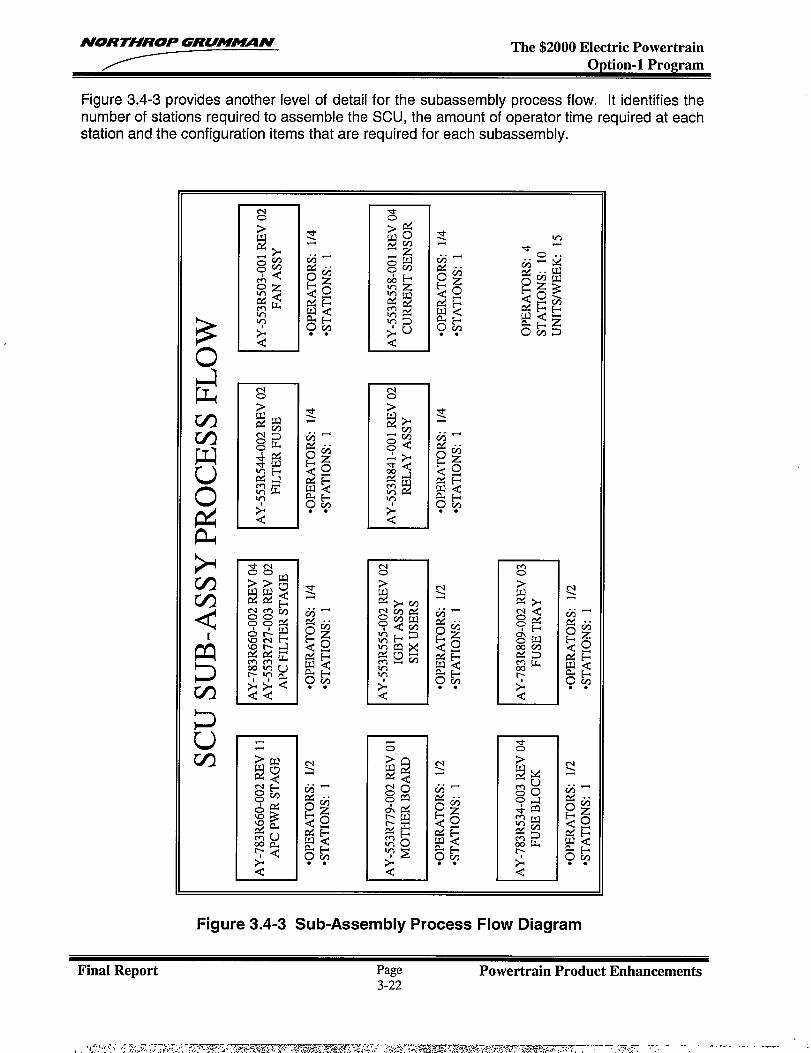
NORTHROP GRU!WUIN The $2000 Electric PowertrainOption-1 Program
Figure 3.4-3 provides another level of detail for the subassembly process flow. It identifies thenumber of stations required to assemble the SCU, the amount of operator time required at eachstation and the configuration items that are required for each subassembly.
ti
In
m0 I
*o I
Figure 3.4-3 Sub-Assembly Process Flow Diagram
Final Report Page Powertrain Product Enhancements3-22
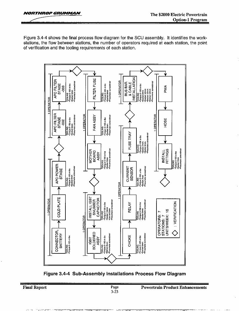
NORTHROP GRUM-N The $2000 Electric PowertrainOption-1 Program
Figure 3.4-4 shows the final process flow diagram for the SCU assembly. It identifies the work-stations, the flow between stations, the number of operators required at each station, the pointof verification and the tooling requirements of each station.
~<0uoc.
c:<01!ac.
,-. 7 -- ‘-,-.--,.-7- -. ,.,,.. . ,,-. . . . .7-?-. , . ...!.-. ,.-. —-- -. . . . . . . . . . . . ... -..<, . . .. . . . . . . . . . .. .
Figure 3.4-4 Sub-Assembly Installations Process Flow Diagram
Final Report Page Powertrain Product Enhancements3-23
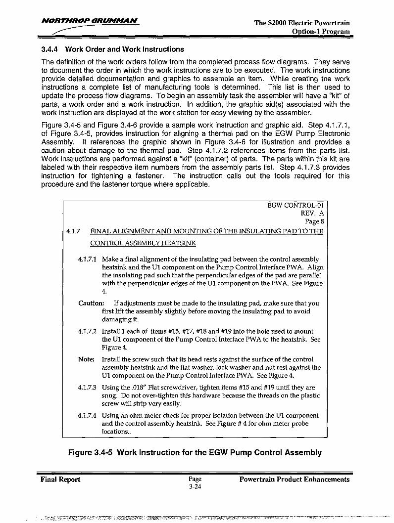
NORTHROP GRU!-N The $2000 Electric PowertrainOption-1 Program
3.4.4 Work Order and Work Instructions
The definition of the work orders follow from the completed process flow diagrams. They serveto document the order in which the work instructions are to be executed. The work instructionsprovide detailed documentation and graphics to assemble an item. While creating the workinstructions a complete list of manufacturing tools is determined. This list is then used toupdate the process flow diagrams. To begin an assembly task the assembler will have a “kit” ofparts, a work order and a work instruction. In addition, the graphic aid(s) associated with thework instruction are displayed at the work station for easy viewing by the assembler.
Figure 3.4-5 and Figure 3.4-6 provide a sample work instruction and graphic aid. Step 4.1.7.1,of Figure 3.4-5, provides instruction for aligning a thermal pad on the EGW Pump ElectronicAssembly. It references the graphic shown in Figure 3.4-6 for illustration and provides acaution about damage to the thermal pad. Step 4.1.7.2 references items from the parts list.Work instructions are performed against a “kit” (container) of parts. The parts within this kit arelabeled with their respective item numbers from the assembly parts list. Step 4.1.7.3 providesinstruction for tightening a fastener. The instruction calls out the tools required for thisprocedure and th~ faste~er torque where applicable.
EGW CONTROL-01REV. A
Page 8
4.1.7 FINAL ALIGNMENT AND MOUNTING OF THE INSULATING PAD TO THE
CONTROL ASSEMBLY HEATSINK
4.1.7.1 Make a final aIignment of the iruxdating pad between the control assemblyheatsink and the U1 component on the Pump Control Interface PWA. Alignthe ir-uxdating pad such that the perpendicular edges of the pad are paraIIelwith the perpendicular edges of the U1 component on the PWA. See Figure4.
Caution If adjustments must be made to the insulating pad, make sure that youfirst lift the assembly sfightly before moving the insulating pad to avoiddamaging it.
4.1.7.2 Install 1 each of items #15, #17, #18 and #19 into the hole used to mountthe U1 component of the Pump Control Interface PWA to the heatsink. SeeFigure 4.
Note Install the screw such that its head rests against the surface of the controlassembly heatsink and the flat washer, lock washer and nut rest against theU1 component on the Pump Control Interface PWA. See Figure 4.
4.1.7.3 Using the .018” Flat screwdriver, tighten items #15 and #19 untiI they aresnug. Do not over-tighten this hardware because the threads on the plasticscrew will strip very easily.
4.1.7.4 Using an ohm meter check for proper isoIation between the U1 componentand the control assembly heatsink. See Figure # 4 for ohm meter probelocations..
Figure 3.4-5 Work Instruction for the EGW Pump Control Assembly
Final ReDort Page Powertrain Product Enhancements
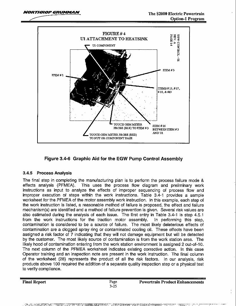
NORTHROP GRUM~N The $2000 Electric PowertrainOption-1 Program
FIGURE #4U1 ATTACHMENT TO HEATSINK
~E8g<<->0
lTEM#2
TO NUT OR COMPONENT BASE
Figure 3.4-6 Graphic Aid for the EGW Pump Control Assembly
3.4.5 Process Analysis
The final step in completing the manufacturing plan is to perform the process failure mode &effects analysis (P FMEA). This uses the process flow diagram and preliminary workinstructions as input to analyze the effects of improper sequencing of process flow andimproper execution of steps within the work instructions. Table 3.4-1 provides a sampleworksheet for the PFMEA of the motor assembly work instruction. In this example, each step ofthe work instruction is listed, a reasonable method of failure is proposed, the effect and failuremechanism(s) are identified and a method of failure prevention is given. Several risk values arealso estimated during the analysis of each issue. The first entry in Table 3.4-1 is step 4.5.1from the work instructions for the traction motor assembly. [n performing this step,contamination is considered to be a source of failure. The most likely deleterious effects ofcontamination are a clogged spray ring or contaminated cooling oil. These effects have beenassigned a risk factor of 7 indicating that they will not damage equipment but will be detectedby the customer. The most likely source of contamination is from the work station area. Thelikely hood of contamination entering from the work station environment is assigned 2 out-of-1 O.The next column of the PFMEA worksheet indicates existing corrective action. In this caseOperator training and an inspection note are present in the work instruction. The final columnof the worksheet (28) represents the product of all the risk factors. In our analysis, riskproducts above 100 required the addition of a separate quality inspection step or a physical testto verify compliance.
Final Report Page Powertrain Product Enhancements3-25
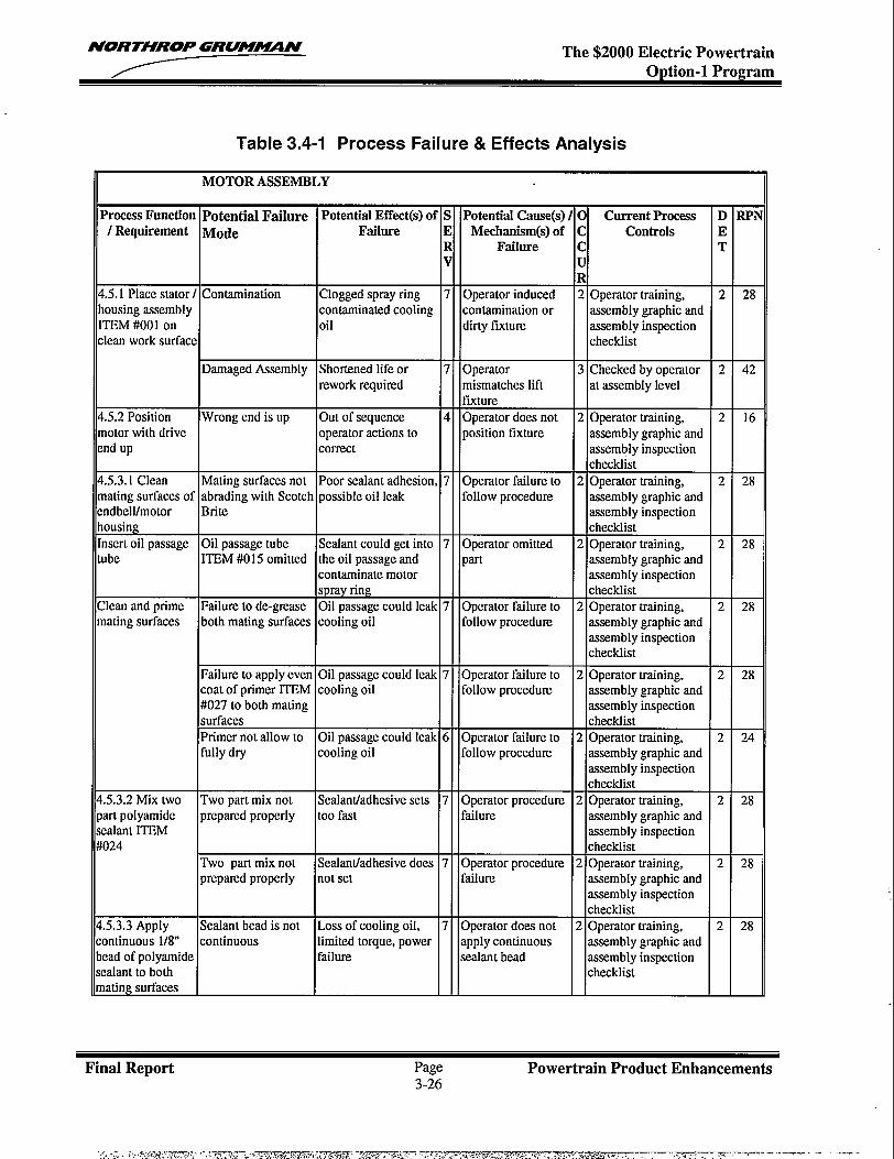
NORTHROP GRUM~N The $2000 Electric PowertrainOption-1 Program
Table 3.4-1 Process Failure & Effects Analysis
MOTOR ASSEMBLY
%oeessFunction Potential Failure Potential Effect(s) of s Potential Cause(s)/ o Current Process D RPNI Requirement Mode Failure E Mechanism(s)of c Controls E
R Failure c Tv u
R.5.1 P1acestator I Contamination Clogged spray ring 7 Operator induced 2 Operator training, 2 28ousing assembly contaminated cooling contamination or assembly graphic andIWM#001 on oil dirty fixture assembly inspectionlean work surface checklist
Damaged Assembly Shortened life or 7 Operator 3 Checked by operator 2 42rework required mismatches lift at assembly level
fixture.5.2 Position Wrong end is up Out of sequence 4 Operator does not 2 Operator training, 2 16lotor with drive operator actions to position fixture assembly graphic andnd up correct assembly inspection
checklist.5.3.1 Clean Mating surfaces not Poor sealant adhesion, 7 Operator failure to 2 Operator training, 2 28lating surfaces of abrading with Scotch possible oil leak follow procedure assembly graphic andndbell/motor Britc assembly inspectionousing checklistlsert oil passage Oil passage tube Sealant could get into 7 Operator omitted 2 Operator training, 2 28lbe ITEM #O15 omitted the oil passage and part assembly graphic and
contaminate motor assembly inspectionspray ring checklist
lean and prime Failure to de-grease Oil passage could leak 7 Operator failure to 2 Operator training, 2 28]ating surfaces both mating surfaces cooling oil follow procedure assembly graphic and
assembly inspectionchecklist
Failure to apply even Oil passage could leak 7 Operator failure to 2 Operator training, 2 28coat of primer ITEM cooling oil follow procedtne assembly graphic and#027 to both mating assembly inspectionsurfaces checklistPrimer not allow to Oil passage could leak 6 Operator failure to 2 Operator training, 2 24fully dry cooling oil follow procedure assembly graphic and
assembly inspectionchecklist
.5.3.2 Mix two Two part mix not Sealant/adhesive sets 7 Operator procedtue 2 Operator training, 2 28art polyamide prepared properly too fast failure assembly graphic and:alant ITEMD24
assembly inspectionchecklist
Two part mix not Sealant/adhesive does 7 Operator procedure 2 Operator training, 2 28prepared properly not set failure assembly graphic and
assembly inspectionchecldist
>5.3.3Apply Sealant bead is not Loss of cooling oil, 7 Operator does not 2 Operator training, 2 28mtinuous 1/8” continuous 1imited torque, power apply continuous assembly graphic andtad of polyamide failure sealant bead assembly inspection!alant to both checklistIating surfaces
Final Report Page Powertrain Product Enhancements3-26
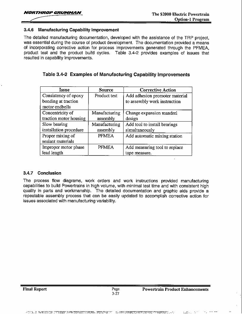
NORTHROP GRUM~N The $2000 Electric Powertrain
3.4.6 Manufacturing Capability Improvement
The detailed manufacturing documentation, developed with the assistance of the TRP project,was essential during the course of product development. The documentation provided a meansof incorporating corrective action for process improvements generated through the PFMEA,product test and the product build cycles. Table 3.4-2 provides examples of issues thatresulted in capability improvements.
Table 3.4-2 Examples of Manufacturing Capability Improvements
Issue Source Corrective Action
Consistency of epoxy Product test Add adhesion promoter material
bonding at traction to assembly work instruction
motor endbells
Concentricity of [ Manufacturing I Change expansion mandrel -‘1traction motor housing assembly design -Slow bearing Manufacturing Add tool to install bearingsinstallation procedure assembly simultaneouslyProper mixing of PFMEA Add automatic mixing stationsealant materialsImproper motor phase PFMEA Add measuring tool to replacelead length I tape measure.
3.4.7 Conclusion
The process flow diagrams, work orders and work instructions provided manufacturingcapabilities to build Powertrains in high volume, with minimal test time and with consistent highquality in parts and workmanship. The detailed documentation and graphic aids provide arepeatable assembly process that can be easily updated to accomplish corrective action forissues associated with manufacturing variability.
Final Report Page Powertrain Product Enhancements3-27
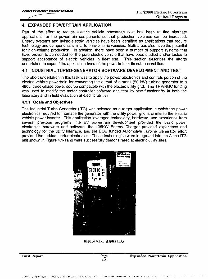
NORTHROP GRUM~N The $2000 Electric PowertrainOption-1 Program
4. EXPANDED POWERTRAIN APPLICATION
Part of the effort to reduce electric vehicle powertrian cost has been to find alternateapplications for the powertrain components so that production volumes can be increased.Energy systems and hybrid-electric vehicles have been identified as applications that requiretechnology and components similar to pure-electric vehicles. Both areas also have the potentialfor high-volume production. In addition, there have been a number of support systems thathave proven to be needed for the pure electric vehicle that have been studied and/or tested tosupport acceptance of electric vehicles in fleet use. This section describes the effortsundertaken to expand the application base of the powertrain or its sub-assemblies.
4.1 INDUSTRIAL TURBO-GENERATOR SOFTWARE DEVELOPMENT AND TEST
The effort undertaken in this task was to apply the power electronics and controls portion of theelectric vehicle powertrain for converting the output of a small (50 kW) turbine-generator to a480v, three-phase power source compatible with the electric utility grid. The TRP/NGC fundingwas used to modify the motor controller software and test its new functionality in both thelaboratory and in field evaluation at electric utilities.
4.1.1 Goals and Objectives
The industrial Turbo Generator (ITG) was selected as a target application in which the powerelectronics required to interface the generator with the utility power grid is similar to the electricvehicle power inverter. This application leveraged technology, hardware, and experience fromseveral previous programs: the EV powertrain development provided the basic powerelectronics hardware and software, the 135KW Battery Charger provided experience andtechnology for the utility interface, and the DOE funded Automotive Turbine Generator effortprovided the turbine starter electronics. These technologies were integrated into the Alpha ITGunit shown in Figure 4.1-1 and were successfully demonstrated at electric utility sites.
Figure 4.1-1 Alpha ITG
Final Report Page Expanded Powertrain Application4-1
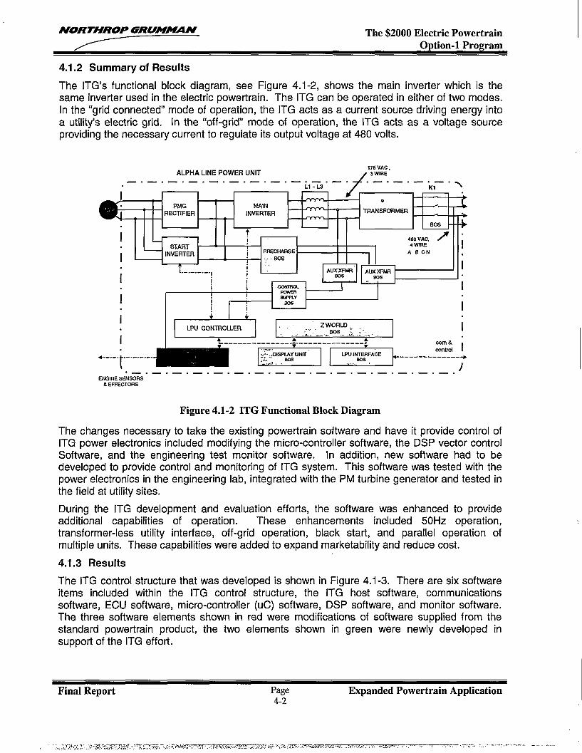
NORTHROP GRUMA4UIN The $2000 Electric PowertrainOption-1 Program
4.1.2 Summary of Results
The ITG’s functional block diagram, see Figure 4.1-2, shows the main inverter which is thesame inverter used in the electric powertrain. The ITG can be operated in either of two modes.In the “grid connected” mode of operation, the ITG acts as a current source driving energy intoa utility’s electric grid. In the “off-grid mode of operation, the ITG acts as a voltage sourceproviding the necessary current to regulate its output voltage at 480 volts.
ALPHA LINE POWER UNIT175 VAC ,
/ 3 WIRE
_/
—.—. — .—. —. —.—. — .—. —. —.. — .—. —. —.LI-Ls \
i
K1
0
PMG MAIN cRECTIFIER INVERTER TRANSFWiMER
vKS
i
++j 4s0 VAC, / i
START 4WIRE
i
,INVERTER ~ PRECHAffiE
II
ABCN
, ---- BW:.
j i1---------
i! I! i! i ~L I i
iI
I I FmYEH
jS4H%Y
eas. ! i
I
i
Jmm311m
E&a I ~~-ZWRLD=I ik-----.------:-:;-?--:-:-_:::I:<’● t-------------. EEEzl L!5!51-------=+
.—. —, —.—. — .—. —. —.—. — .—. —. —.—. — .—. -ENGINE SENSORS
& EFFEcTIXS
Figure 4.1-2 ITG Functional Block Diagram
The changes necessary to take the existing powertrain software and have it provide control ofITG power electronics included modifying the micro-controller software, the DSP vector controlSoftware, and the engineering test monitor software. In addition, new software had to bedeveloped to provide control and monitoring of ITG system. This software was tested with thepower electronics in the engineering lab, integrated with the PM turbine generator and tested inthe field at utility sites.
During the ITG development and evaluation efforts, the software was enhanced to provideadditional capabilities of operation. These enhancements included 50Hz operation,transformer-less utility interface, off-grid operation, black start, and parallel operation ofmultiple units. These capabilities were added to expand marketability and reduce cost.
4.1.3 Results
The ITG control structure that was developed is shown in Figure 4.1-3. There are six softwareitems included within the ITG control structure, the ITG host software, communicationssoftware, ECU software, micro-controller (uC) software, DSP software, and monitor software.The three software elements shown in red were modifications of software supplied from thestandard powertrain product, the two elements shown in green were newly developed insupport of the ITG effort.
Final Report Page Expanded Powertrain Application4-2
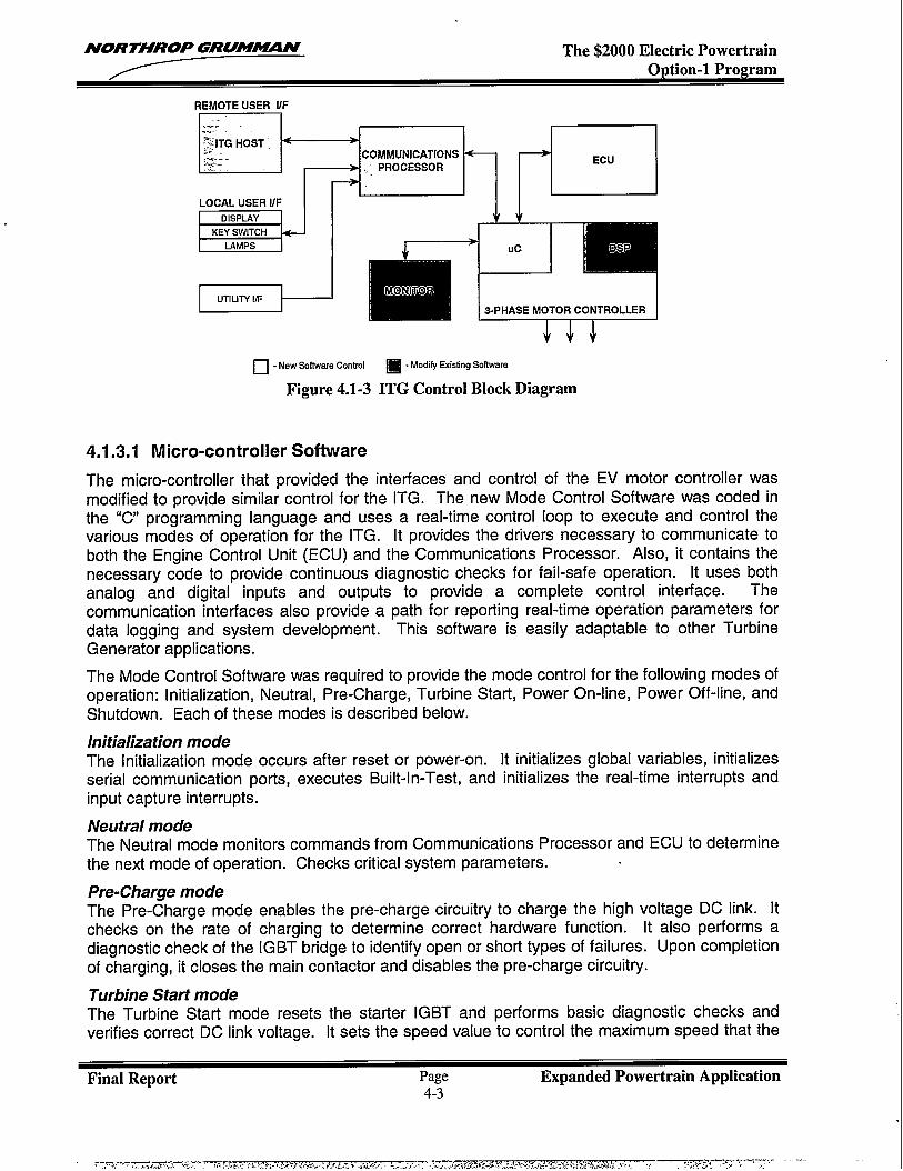
NORTHROP GRU!WVIN The $2000 Electric Powertrain
REMOTE USER UF
~~,:,.%iTG HOST ~ I I
EcilLOCAL USER UF
m
I II UTIUTYIF l—
-4 COMMUNICATIONS,. PROCESSOR
-+ 7n=-7 v
llrilli,+:Uc Ds
ONTO
s-PHASE MOTOR CONTROLLER
❑ - New Software Control ❑ -Modify Existing Software
Figure 4.1-3 ITG Control Block Diagram
4.1.3.1 Micro-controller Software
The micro-controller that provided the interfaces and control of the EV motor controller wasmodified to provide similar control for the ITG. The new Mode Control Software was coded inthe “C programming language and uses a real-time control loop to execute and control thevarious modes of operation for the ITG. It provides the drivers necessary to communicate toboth the Engine Control Unit (ECU) and the Communications Processor. Also, it contains thenecessary code to provide continuous diagnostic checks for fail-safe operation. It uses bothanalog and digital inputs and outputs to provide a complete control interface. Thecommunication interfaces also provide a path for reporting real-time operation parameters fordata logging and system development. This software is easily adaptable to other TurbineGenerator applications.
The Mode Control Software was required to provide the mode control for the following modes ofoperation: Initialization, Neutral, Pre-Charge, Turbine Start, Power On-line, Power Off-1ine, andShutdown. Each of these modes is described below.
Initialization modeThe Initialization mode occurs after reset or power-on. It initializes global variables, initializesserial communication ports, executes Built-In-Test, and initializes the real-time interrupts andinput capture interrupts.
Neutral modeThe Neutral mode monitors commands from Communications Processor and ECU to determinethe next mode of operation. Checks critical system parameters.
Pre-Charge modeThe Pre-Charge mode enables the pre-charge circuitry to charge the high voltage DC link. Hchecks on the rate of charging to determine correct hardware function. It also performs adiagnostic check of the IGBT bridge to identify open or short types of failures. Upon completionof charging, it closes the main contactor and disables the pre-charge circuitry.
Turbine Start modeThe Turbine Start mode resets the starter IGBT and performs basic diagnostic checks andverifies correct DC link voltage. It sets the speed value to control the maximum speed that the
Final Report Page Expanded Powertrain Application4-3
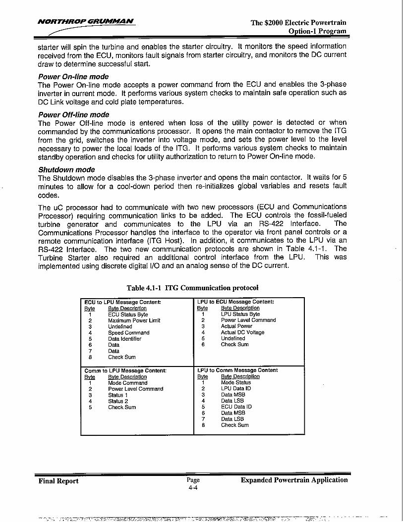
NORTHROP GRUMUN The $2000 Electric PowertrainOption-1 Program
starter will spin the turbine and enables the starter circuitry. It monitors the speed informationreceived from the ECU, monitors fault signals from starter circuitry, and monitors the DC currentdraw to determine successful start.
Power On-line modeThe Power On-line mode accepts a power command from the ECU and enables the 3-phaseinverter in current mode. [t performs various system checks to maintain safe operation such asDC Link voltage and cold plate temperatures.
Power Off-line modeThe Power Off-line mode is entered when loss of the utility power is detected or whencommanded by the communications processor. It opens the main contactor to remove the ITGfrom the grid, switches the inverter into voltage mode, and sets the power level to the levelnecessary to power the local loads of the ITG. It performs various system checks to maintainstandby operation and checks for utility authorization to return to Power On-line mode.
Shutdown modeThe Shutdown mode disables the 3-phase inverter and opens the main contactor. It waits for 5minutes to allow for a cool-down period then re-initializes global variables and resets faultcodes.
The UC processor had to communicate with two new processors (ECU and CommunicationsProcessor) requiring communication links to be added. The ECU controls the fossil-fueledturbine generator and communicates to the LPU via an RS-422 Interface. TheCommunications Processor handles the interface to the operator via front panel controls or aremote communication interface (ITG Host). In addition, it communicates to the LPU via anRS-422 Interface. The two new communication protocols are shown in Table 4.1-1. TheTurbine Starter also required an additional control interface from the LPU. This wasimplemented using discrete digital 1/0 and an analog sense of the DC current.
Table 4.1-1 ITG Communication protocol
ECU to LPU Message Content LPU to ECU Mesaage Contank
131Jt& Bvta Description &t& Bvte DascrirMion
1 ECU Status Byte 1 LPU Status Byte2 Maximum Power Limit 2 Power Leval Command3 Undefined 3 Actual Power4 Speed Command 4 Actual DC Voltage5 Data Identifier 5 Undafined6 Data 6 Check Sum7 Data8 Check Sum
Comm to LPU Message Contenti LPU to Comm Massage Content
B+? Bvte Description Q@ Bvte i)aSCriDtiOn
Mode Command 1 Mode Status2 Power Level Command 2 LPU Data ID3 Status 1 3 Data MSB4 Status 2 4 Data LSB5 Check Sum 5 ECU Data ID
6 Data MSB7 Data LSB8 Check Sum
Final Report Page Expanded Powertrain Application4-4
NORTHROP GRUM_N The $2000 Electric PowertrainO@ion-1 Prom-am
4.1.3.2 DSP Vector Control Software
The DSP provides the actual 3-phase control of the IGBT’s driving an AC induction motor in amotor controller application. In this case, the IGBT’s are driving the utility grid at a fixedfrequency of 60 Hz. The basic vector control algorithms remain the same but there are a fewdifferences as outlined below.
The code was modified from using a resolver feedback for motor position to using a utility gridfrequency signal feedback. [f the ITG is to be able to connect to a utility grid and drive poweronto the grid, it must be able to sense and be synchronized to the utility voltage. Also, if the ITGis operating in a stand-alone mode or the grid is temporarily disconnected then its output powerfrequency must be self-regulating. The line synchronization code provides the following featuresfor the ITG:
. Synchronized output power to the utility grid
. Validation of the grid frequency
. Power factor control● Self regulated output frequency during stand-alone mode. Smooth transition from stand-alone to grid connected mode
Fault protection code was developed to monitor the AC voltage level of the utility grid. The ITGwill go off-line if either an over-voltage or under-voltage condition is sensed. In “On-Grid” modeof operation, the ITG unit is operating as a current source. In this mode, the DSP uses currentfeedback to regulate its output power. In the case of a fault or loss of utility authorization, theITG unit will transition to off-line mode and operate as a voltage source. In this mode, the DSPcode senses DC link voltage and uses a feed-forward control loop to maintain the proper outputvoltage. As a voltage source, the ITG provides the power needed to run the local loads of thesystem.
4.1.3.3 Monitor Software
The PC based engineering monitor provides real-time monitoring of the modes and parametersassociated with the operation of the LPU. [t communicates with the LPU via a standard RS-232interface. It also provides a method for re-programming the LPU code and modifying systemparameters. This software was updated to include all the new values and formatting for the ITGsystem.
4.1.3.4 Communications Processor Software
The communications processor, shown in Figure 4.1-4, interfaces with the front panel for localcontrol and displays of the ITG’s output and with the grid operators via a telephone line. Thecontrol-program performs the following basic functions: a) maintains a real time clock, whichprovides the capability to turn the unit on or off at some user selected (via the ITG Remote Hostprogram) date and time, b) processes all front panel and other system status inputs, providesthis information to the LPU processor and the Remote Host, and uses it for internal processingc) processes communications with the Remote Host, d) processes communications with theLPU processor, e) controls the outputs which drive the front panel indicating lamps, and f)processes the information for, and drives the front panel alphanumeric display.
Final Report Page Expanded Powertrain Application4-5
,..... .., .-.,7;.=,. ,, . ...-., , -- .. . . ~.’>...f,>%,. .-. ?. . .. . -,-.. . ,. :...W:W: ,.3.-, .... .“ . — -s “’. .. -—
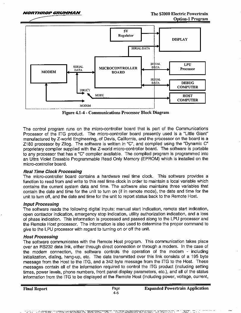
NORTHROP GRUMM21N The $2000 Electric PowertrainOWion-1 ProPram
5VRegulator
●
DISPLAY
I
I SERIAL.DATA
ISERIAL
4DATA
MICROCONTROLLERMODEM
A ● BOARD
A
DIRECT
- k MODE
c kSE IAL LPUD TA
● Processor
SERIALD~TA
4 ●DEBUG
COMPUTER
IHOST
➤ COMPUTER
MODEM
Figure 4.1-4- Communications Processor Block Diagram
The control program runs on the micro-controller board that is part of the CommunicationsProcessor of the ITG product. The micro-controller board presently used is a “Little Giant”manufactured by Z-world Engineering, of Davis, California, and the processor on the board is aZ180 processor by Zilog. The software is written in “C, and compiled using the “Dynamic Cproprietary compiler supplied with the Z-world micro-controller board. The software is portableto any processor that has a “C compiler available. The compiled program is programmed intoan Ultra Violet Erasable Programmable Read Only Memory (EPROM) which is installed on themicro-controller board.
Real Time Clock ProcessingThe micro-controller board contains a hardware real time clock. This software provides afunction to read from and write to this real time clock in order to maintain a local variable whichcontains the current system data and time. The software also maintains three variables thatcontain the date and time for the unit to turn on (if in remote mode), the date and time for theunit to turn off, and the date and time for the unit to report status back to the Remote Host.
Input ProcessingThe software reads the following digital inputs: manual start indication, remote start indication,open contactor indication, emergency stop indication, utility authorization indication, and a lossof phase indication. This information is processed and passed along to the LPU processor andthe Remote Host processor. The information is also used to determine the proper command togive to the LPU processor with regard to turning on or off the unit.
Host ProcessingThe software communicates with the Remote Host program. This communication takes placeover an RS232 data link, either through direct connection or through a modem. In the case ofthe modem connection, the software controls the operation of the modem - includinginitialization, dialing, hang-up, etc. The data transmitted over this link consists of a 195 bytemessage from the Host to the ITG, and a 342 byte message from the ITG to the Host. Thesemessages contain all of the information required to control the ITG product (including settingtimes, power levels, phone numbers, front panel display parameters, etc.), and all of the statusinformation from the ITG to be displayed at the Remote Host (including power, voltage, current,
Final Report Page Expanded Powertrain Application4-6
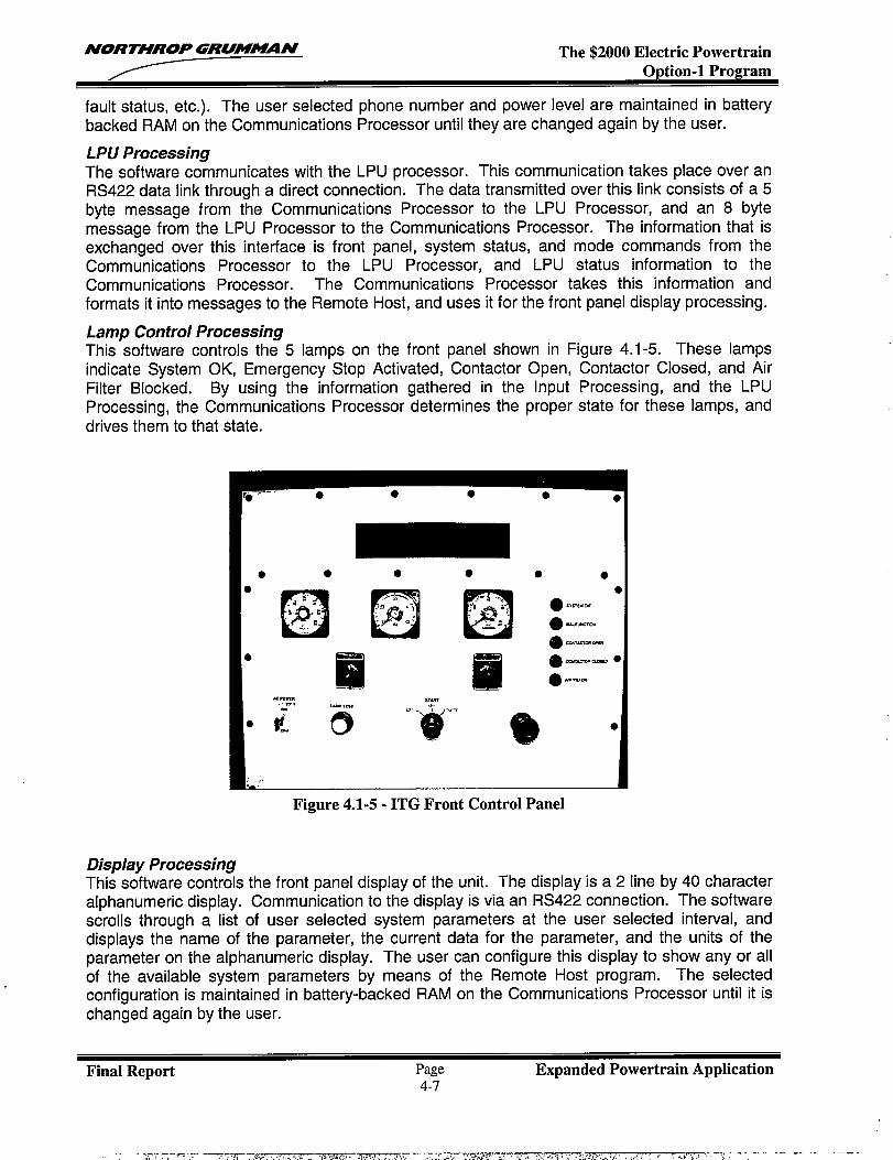
AfORTHROP GRUMAZQN The $2000 Electric Powertrain
fault status, etc.). The user selected phone number and power level are maintained in batterybacked RAM on the Communications Processor until they are changed again by the user.
LPU ProcessingThe software communicates with the LPU processor. This communication takes place over anRS422 data link through a direct connection. The data transmitted over this link consists of a 5byte message from the Communications Processor to the LPU Processor, and an 8 bytemessage from the LPU Processor to the Communications Processor. The information that isexchanged over this interface is front panel, system status, and mode commands from theCommunications Processor to the LPU Processor, and LPU status information to theCommunications Processor. The Communications Processor takes this information andformats it into messages to the Remote Host, and uses it for the front panel display processing.
Lamp Control ProcessingThis software controls the 5 lamps on the front panel shown in Figure 4.1-5. These lampsindicate System OK, Emergency Stop Activated, Contactor Open, Contactor Closed, and AirFilter Blocked. By using the information gathered in the Input Processing, and the LPUProcessing, the Communications Processor determines the proper state for these lamps, anddrives them to that state.
● ● ● ● ● ●
Eil
Figure 4.1-5- ITG Front Control Panel
Display ProcessingThis software controls the front panel display of the unit. The display is a 2 line by 40 characteralphanumeric display. Communication to the display is via an RS422 connection. The softwarescrolls through a list of user selected system parameters at the user selected interval, anddisplays the name of the parameter, the current data for the parameter, and the units of theparameter on the alphanumeric display. The user can configure this display to show any or allof the available system parameters by means of the Remote Host program. The selectedconfiguration is maintained in battery-backed RAM on the Communications Processor until it ischanged again by the user.
Final Report Page Expanded Powertrain Application4-7
., .- T7 ,-.— = .T - ---ZTZ--. L. . . . , % ,,?. w ,.1 ..,..., . $ .,! --7 ~- . . . ~,,k.s- . . , ., ,. .+.. .>. , ,,. . . . . , , ..,--, ; ,- >-!! ; - -. -. --- --. . . . .,, < s .,
—.
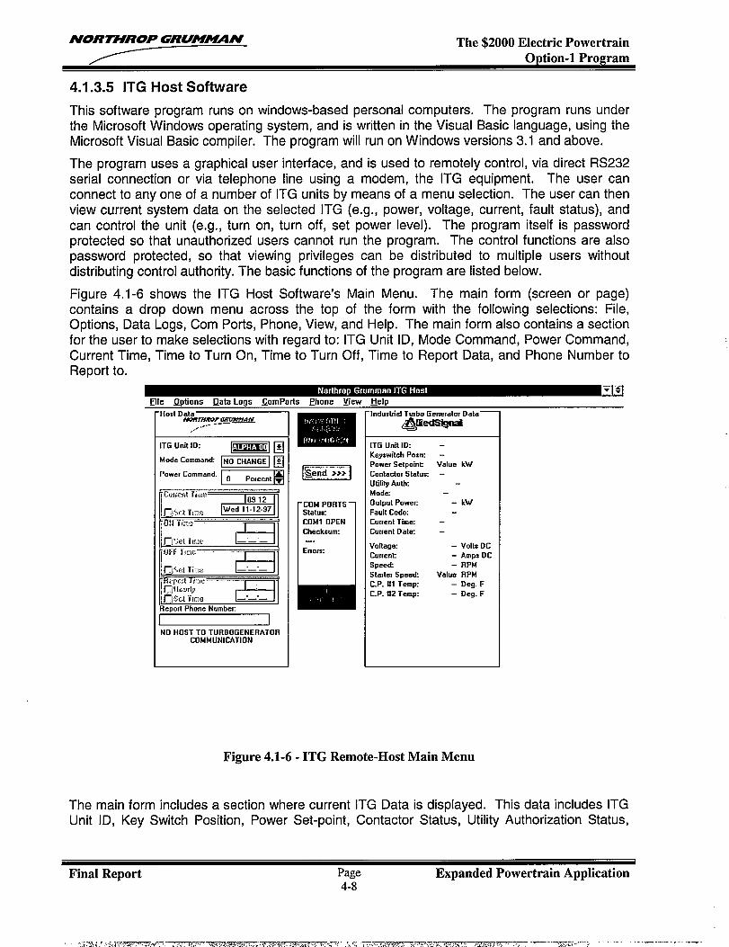
NORTHROP GRUM?N The $2000 Electric PowertrainOption-1 Program
4.1.3.5 ITG Host Software
This software program runs on windows-based personal computers. The program runs underthe Microsoft Windows operating system, and is written in the Visual Basic language, using theMicrosoft Visual Basic compiler. The program will run on Windows versions 3.1 and above.
The program uses a graphical user interface, and is used to remotely control, via direct RS232serial connection or via telephone line using a modem, the ITG equipment. The user canconnect to any one of a number of ITG units by means of a menu selection. The user can thenview current system data on the selected ITG (e.g., power, voltage, current, fault status), andcan control the unit (e.g., turn on, turn off, set power level). The program itself is passwordprotected so that unauthorized users cannot run the program. The control functions are alsopassword protected, so that viewing privileges can be distributed to multiple users withoutdistributing control authority. The basic functions of the program are listed below.
Figure 4,1-6 shows the ITG Host Software’s Main Menu. The main form (screen or page)contains a drop down menu across the top of the form with the following selections: File,Options, Data Logs, Corn Ports, Phone, View, and Help. The main form also contains a sectionfor the user to make selections with regard to: ITG Unit ID, Mode Command, Power Command,Current Time, Time to Turn On, Time to Turn Off, Time to Report Data, and Phone Number toReport to.
‘Host DatalYeanWOP—AN.-.. --
,.-
ITGUnit ID:-E
Mode Command ~ ~
‘“’’’’’command” ~
mII I II
NO HOST TO TURBOGENERATORCOMMUNICATION
IEiiElCOM PORTS
11
Status:CDM1 OPENChecksum:—
ErIoIx
IndustrialTurbo Generator Data—
@hxQ@
ITG Unit ID:KeyswitchPOSIXPower SetpOintContador Statu=UtilityAuIhMode
Dutput powec
Fault coda
Current Tim=
Cuuent Date
Voltage
Cuwenk
speedSta:tef Speed
C.P. #l Temp
C.P. #2 Temp
Value kW
- kW
- volts Oc
- Amps DC
– RPMValue RPM
– Deg. F- Oeg. F
Figure 4.1-6- ITG Remote-Host Main Menu
The main form includes a section where current ITG Data is displayed. This data includes ITGUnit ID, Key Switch Position, Power Set-point, Contactor Status, Utility Authorization Status,
Final Report Page Expanded Powertrain Application4-8
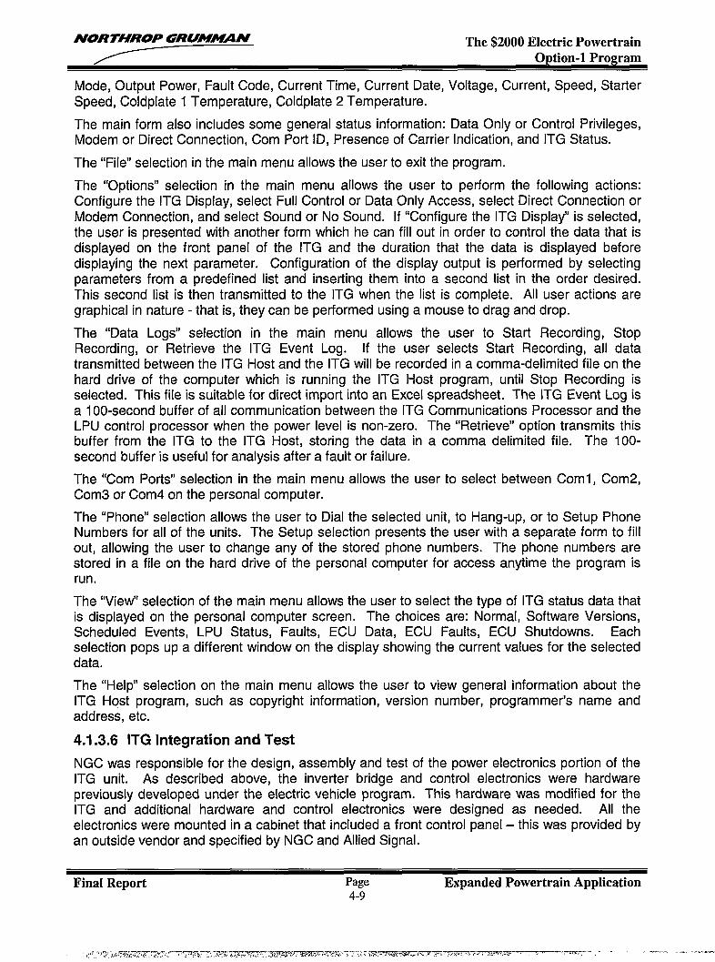
NORTHROP GRUM-N The $2000 Electric PowertrainODtion-1 Pro~ram
Mode, Output Power, Fault Code, Current Time, Current Date, Voltage, Current, Speed, StarterSpeed, Coldplate 1 Temperature, Coldplate 2 Temperature.
The main form also includes some general status information: Data Only or Control Privileges,Modem or Direct Connection, Corn Port ID, Presence of Carrier Indication, and ITG Status.
The “File” selection in the main menu allows the user to exit the program.
The “Options” selection in the main menu allows the user to perform the following actions:Configure the ITG Display, select Full Control or Data Only Access, select Direct Connection orModem Connection, and select Sound or No Sound. [f “Configure the ITG Display” is selected,the user is presented with another form which he can fill out in order to control the data that isdisplayed on the front panel of the ITG and the duration that the data is displayed beforedisplaying the next parameter. Configuration of the display output is performed by selectingparameters from a predefine list and inserting them into a second list in the order desired.This second list is then transmitted to the ITG when the list is complete. All user actions aregraphical in nature - that is, they can be performed using a mouse to drag and drop.
The “Data Logs” selection in the main menu allows the user to Start Recording, StopRecording, or Retrieve the ITG Event Log. If the user selects Start Recording, all datatransmitted between the ITG Host and the ITG will be recorded in a comma-delimited file on thehard drive of the computer which is running the ITG Host program, until Stop Recording isselected. This file is suitable for direct import into an Excel spreadsheet. The ITG Event Log isa 100-second buffer of all communication between the ITG Communications Processor and theLPU control processor when the power level is non-zero. The “Retrieve” option transmits thisbuffer from the ITG to the ITG Host, storing the data in a comma delimited file. The 100-
second buffer is useful for analysis after a fault or failure.
The “Corn Ports” selection in the main menu allows the user to select between Coml, Com2,Com3 or Com4 on the personal computer.
The “Phone” selection allows the user to Dial the selected unit, to Hang-up, or to Setup PhoneNumbers for all of the units. The Setup selection presents the user with a separate form to fillout, allowing the user to change any of the stored phone numbers. The phone numbers arestored in a file on the hard drive of the personal computer for access anytime the program isrun.
The “View” selection of the main menu allows the user to select the type of ITG status data thatis displayed on the personal computer screen. The choices are: Normal, Software Versions,Scheduled Events, LPU Status, Faults, ECU Data, ECU Faults, ECU Shutdowns. Eachselection pops up a different window on the display showing the current values for the selecteddata.
The “Help” selection on the main menu allows the user to view general information about theITG Host program, such as copyright information, version number, programmer’s name andaddress, etc.
4.1.3.6 ITG Integration and Test
NGC was responsible for the design, assembly and test of the power electronics portion of theITG unit. As described above, the inverter bridge and control electronics were hardwarepreviously developed under the electric vehicle program. This hardware was modified for theITG and additional hardware and control electronics were designed as needed. All theelectronics were mounted in a cabinet that included a front control panel – this was provided byan outside vendor and specified by NGC and Allied Signal.
Final Report Page Expanded Powertrain Application4-9
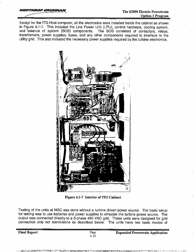
NORTHROP GRUM~N The $2000 Electric PowertrainOption-1 Program
Except for the ITG Host computer, all the electronics were installed inside the cabinet as shownin Figure 4.1-7. This included the Line Power Unit (LPU), control hardware, cooling system,and balance of system (BOS) components. The BOS consisted of contractors, relays,transformers, power supplies, fuses, and any other components required to interface to theutility grid. This also included the necessary power supplies required by the turbine electronics.
Figure 4.1-7 Interior of ITG Cabinet
Testing of the units at NGC was done without a turbine driven power source. The basic setupfor testing was to use batteries and power supplies to simulate the turbine power source. Theoutput was connected directly to a 3-phase 480 VAC grid. These units were designed for gridconnection only not stand-alone as described below. The units have two basic modes of
Final Report Page Expanded Powertrain Application4-1o
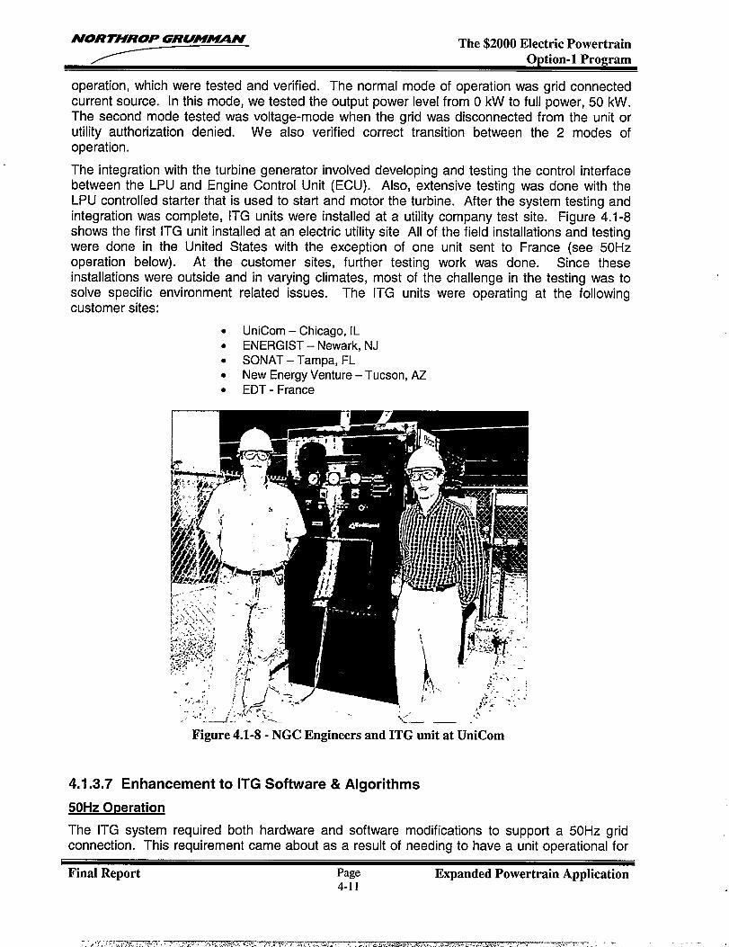
NORTHROP GRUM’N The $2000 Electric PowertrainOption-1 Program
operation, which were tested and verified. The normal mode of operation was grid connectedcurrent source. In this mode, we tested the output power level from O kW to full power, 50 kW.The second mode tested was voltage-mode when the grid was disconnected from the unit orutility authorization denied. We also verified correct transition between the 2 modes ofoperation.
The integration with the turbine generator involved developing and testing the control interfacebetween the LPU and Engine Control Unit (ECU). Also, extensive testing was done with theLPU controlled starter that is used to start and motor the turbine. After the system testing andintegration was complete, ITG units were installed at a utility company test site. Figure 4.1-8shows the first ITG unit installed at an electric utility site All of the field installations and testingwere done in the United States with the exception of one unit sent to France (see 50Hzoperation below). At the customer sites, further testing work was done. Since theseinstallations were outside and in varying climates, most of the challenge in the testing was tosolve specific environment related issues. The ITG units were operating at the followingcustomer sites:
. UniCom – Chicago, IL
. ENERGIST - Newark, NJ
. SONAT – Tampa, FL
. New Energy Venture – Tucson, AZ
. EDT - France
..., :“/’ :
Figure 4.1-8- NGC Engineers and ITG unit at UniCom
4.1.3.7 Enhancement to ITG Software & Algorithms
50Hz O~eration
The ITG system required both hardware and software modifications to support a 50Hz gridconnection. This requirement came about as a result of needing to have a unit operational for
Final Report Page Expanded Powertrain Application4-11
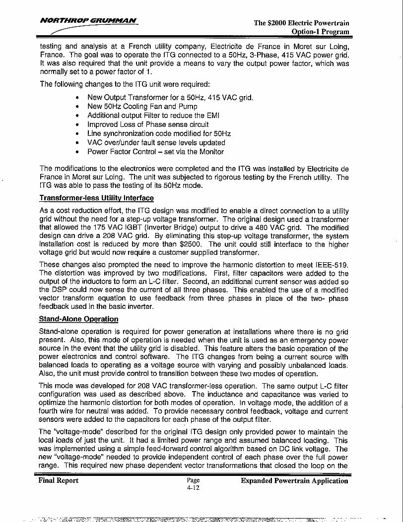
NORTHROP GRUM~N The $2000 Electric PowertrainOption-1 Program
testing and analysis at a French utility company, Electricity de France in Moret sur Loing,France. The goal was to operate the ITG connected to a 50 Hz, 3-Phase, 415 VAC power grid.It was also required that the unit provide a means to vary the output power factor, which wasnormally set to a power factor of 1.
The following
●
●
●
●
●
●
●
changes to the ITG unit were required:
New Output Transformer for a 50 Hz, 415 VAC grid.New 50Hz Cooling Fan and PumpAdditional output Filter to reduce the EMIImproved Loss of Phase sense circuitLine synchronization code modified for 50HzVAC over/under fault sense levels updated
Power Factor Control – set via the Monitor
The modifications to the electronics were completed and the TG was installed bv Electricity deFrance in Moret sur Loing. The unit was subjected to rigorous testing by the Fre~ch utility. TheITG was able to pass the testing of its 50Hz mode.
Transformer-less Utilitv Interface
As a cost reduction effort, the ITG design was modified to enable a direct connection to a utilitygrid without the need for a step-up voltage transformer. The original design used a transformerthat allowed the 175 VAC IGBT (Inverter Bridge) output to drive a 480 VAC grid. The modifieddesign can drive a 208 VAC grid. By eliminating this step-up voltage transformer, the systeminstallation cost is reduced by more than $2500. The unit could still interface to the highervoltage grid but would now require a customer supplied transformer.
These changes also prompted the need to improve the harmonic distortion to meet IEEE-519.The distortion was improved by two modifications. First, filter capacitors were added to theoutput of the inductors to form an L-C filter. Second, an additional current sensor was added sothe DSP could now sense the current of all three phases. This enabled the use of a modifiedvector transform equation to use feedback from three phases in place of the two- phasefeedback used in the basic inverter.
Stand-Alone Operation
Stand-alone operation is required for power generation at installations where there is no gridpresent. Also, this mode of operation is needed when the unit is used as an emergency powersource in the event that the utility grid is disabled. This feature alters the basic operation of thepower electronics and control software. The ITG changes from being a current source withbalanced loads to operating as a voltage source with varying and possibly unbalanced loads.Also, the unit must provide control to transition between these two modes of operation.
This mode was developed for 208 VAC transformer-less operation. The same output L-C filterconfiguration was used as described above. The inductance and capacitance was varied tooptimize the harmonic distortion for both modes of operation. In voltage mode, the addition of afourth wire for neutral was added. To provide necessary control feedback, voltage and currentsensors were added to the capacitors for each phase of the output filter.
The “voltage-mode” described for the original ITG design only provided power to maintain thelocal loads of just the unit. It had a limited power range and assumed balanced loading. Thiswas implemented using a simple feed-forward control algorithm based on DC link voltage. Thenew “voltage-mode” needed to provide independent control of each phase over the full powerrange. This required new phase dependent vector transformations that closed the loop on the
Final Report Page Expanded Powertrain Application4-12
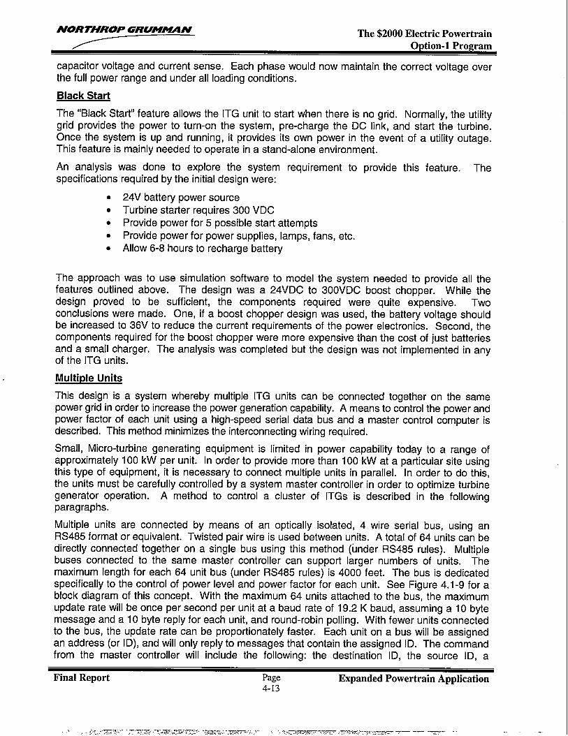
NORTHROP GRUMJWMf The $2000 Electric PowertrainOption-1 Program
capacitor voltage and current sense. Each phase would now maintain the correct voltage overthe full power range and under all loading conditions.
Black Start
The “Black Start” feature allows the ITG unit to start when there is no grid. Normally, the utilitygrid provides the power to turn-on the system, pre-charge the DC link, and start the turbine.Once the system is up and running, it provides its own power in the event of a utility outage.This feature is mainly needed to operate in a stand-alone environment.
An analysis was done to explore the system requirement to provide this feature. Thespecifications required by the initial design were:
●
●
●
●
●
The approach
24V battery power source
Turbine starter requires 300 VDCProvide power for 5 possible start attemptsProvide power for power supplies, lamps, fans, etc.Allow 6-8 hours to recharge battery
was to use simulation software to model the svstem needed to movide all thefeatures outlined above. The design was a 24VDC to 300VDC boost chopper. While thedesign proved to be sufficient, the components required were quite expensive. Twoconclusions were made. One, if a boost chopper design was used, the battery voltage shouldbe increased to 36V to reduce the current requirements of the power electronics. Second, thecomponents required for the boost chopper were more expensive than the cost of just batteriesand a small charger. The analysis was completed but the design was not implemented in anyof the ITG units.
Multiple Units
This design is a system whereby multiple ITG units can be connected together on the samepower grid in order to increase the power generation capability. A means to control the power andpower factor of each unit using a high-speed serial data bus and a master control computer isdescribed. This method minimizes the interconnecting wiring required.
Small, Micro-turbine generating equipment is limited in power capability today to a range ofapproximately 100 kW per unit. [n order to provide more than 100 kW at a particular site usingthis type of equipment, it is necessary to connect multiple units in parallel. [n order to do this,the units must be carefully controlled by a system master controller in order to optimize turbinegenerator operation. A method to control a cluster of ITGs is described in the followingparagraphs.
Multiple units are connected by means of an optically isolated, 4 wire serial bus, using anRS485 format or equivalent. Twisted pair wire is used between units. A total of 64 units can bedirectly connected together on a single bus using this method (under RS485 rules). Multiplebuses connected to the same master controller can support larger numbers of units. Themaximum length for each 64 unit bus (under RS485 rules) is 4000 feet. The bus is dedicatedspecifically to the control of power level and power factor for each unit. See Figure 4.1-9 for ablock diagram of this concept. With the maximum 64 units attached to the bus, the maximumupdate rate will be once per second per unit at a baud rate of 19.2 K baud, assuming a 10 bytemessage and a 10 byte reply for each unit, and round-robin polling. With fewer units connectedto the bus, the update rate can be proportionately faster. Each unit on a bus will be assignedan address (or ID), and will only reply to messages that contain the assigned ID. The commandfrom the master controller will include the following: the destination ID, the source ID, a
Final Report Page Expanded Powertrain Application4-13
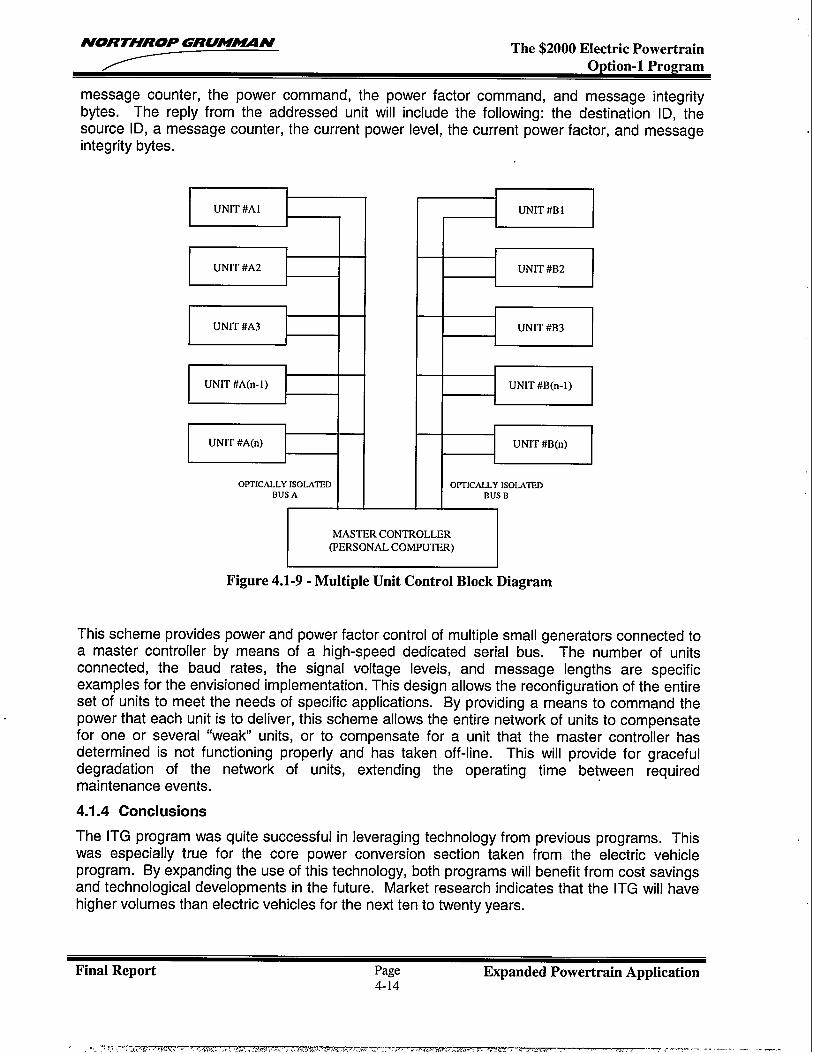
NORTHROP GRU?!N— The $2000 Electric Powertrain
message counter, the power command, the power factor command, and message integritybytes. The reply from the addressed unit will include the following: the destination ID, thesource ID, a message counter, the current power level, the current power factor, and messageintegrity bytes.
‘“’cA%’’i’’”m”MASTER CONTROLLER
(PERSONAL COMPUTER)
Figure 4.1-9- Multiple Unit Control Block Diagram
This scheme provides power and power factor control of multiple small generators connected toa master controller by means of a high-speed dedicated serial bus. The number of unitsconnected, the baud rates, the signal voltage levels, and message lengths are specificexamples for the envisioned implementation. This design allows the reconfiguration of the entireset of units to meet the needs of specific applications. By providing a means to command thepower that each unit is to deliver, this scheme allows the entire network of units to compensatefor one or several “weak” units, or to compensate for a unit that the master controller hasdetermined is not functioning properly and has taken off-line. This will provide for gracefuldegradation of the network of units, extending the operating time between requiredmaintenance events.
4.1.4 Conclusions
The ITG program was quite successful in leveraging technology from previous programs. Thiswas especially true for the core power conversion section taken from the electric vehicleprogram. By expanding the use of this technology, both programs will benefit from cost savingsand technological developments in the future. Market research indicates that the ITG will havehigher volumes than electric vehicles for the next ten to twenty years.
Final Report Page Expanded Powertrain Application4-14
r. -:: ; ,--:-,z77ztmTw T——=-------+% J. ...,... ... ,-. . ---?., > .,, S.>,. -J.*. .>... . . . . . . . . . . . . . . ..- .. —.- . . . .-. .—. ..— . —..
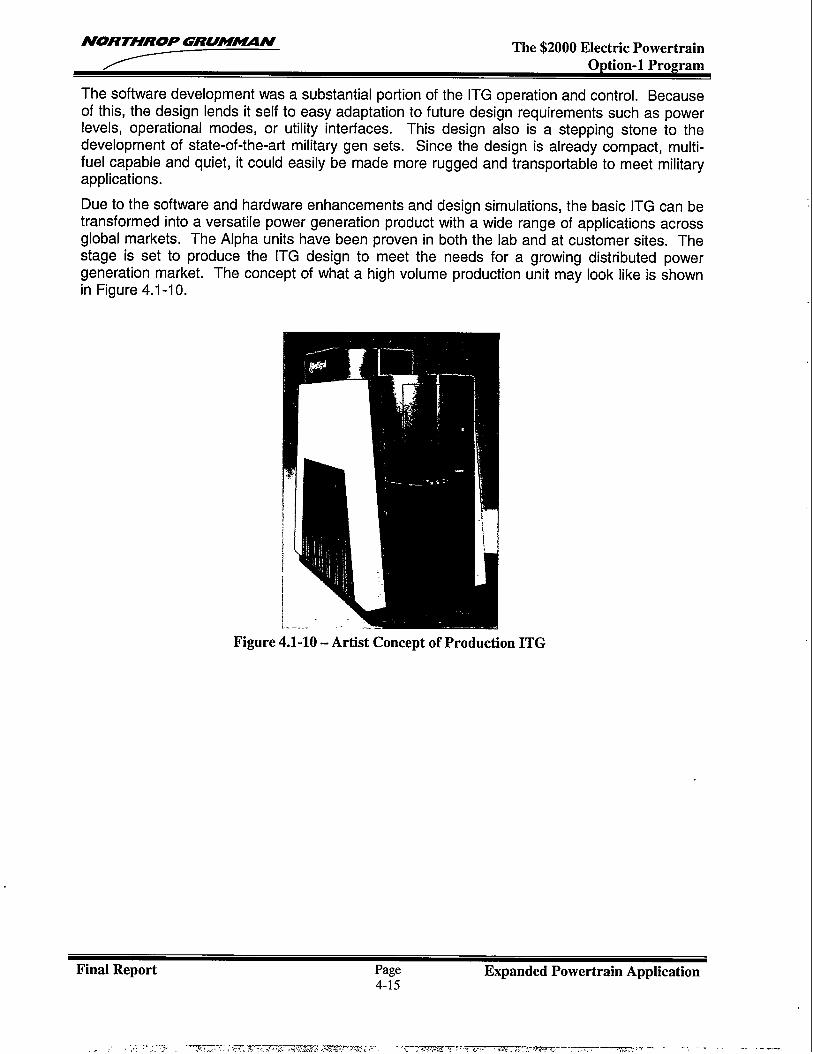
NORTHROP GRUM~N The $2000 Electric PowertrainOption-1 Program
The software development was a substantial portion of the ITG operation and control. Becauseof this, the design lends it self to easy adaptation to future design requirements such as powerlevels, operational modes, or utility interfaces. This design also is a stepping stone to thedevelopment of state-of-the-art military gen sets. Since the design is already compact, multi-fuel capable and quiet, it could easily be made more rugged and transportable to meet militaryapplications.
Due to the software and hardware enhancements and design simulations, the basic ITG can betransformed into a versatile power generation product with a wide range of applications acrossglobal markets. The Alpha units have been proven in both the lab and at customer sites. Thestage is set to produce the ITG design to meet the needs for a growing distributed powergeneration market. The concept of what a high volume production unit may look like is shownin Figure 4.1-10.
j
.-
!
L...
Figure 4.1-10- Artist Concept of Production ITG
Final Report Page Expanded Powertrain Application4-15
.! ,.: :, :~-,-,. Y-.-T ..’>=::Z?:---- - ~wr ,7:,-L.,...,.,,+ --.--,mmT7 ~.n.-.. ... .- -....., . --.:. -
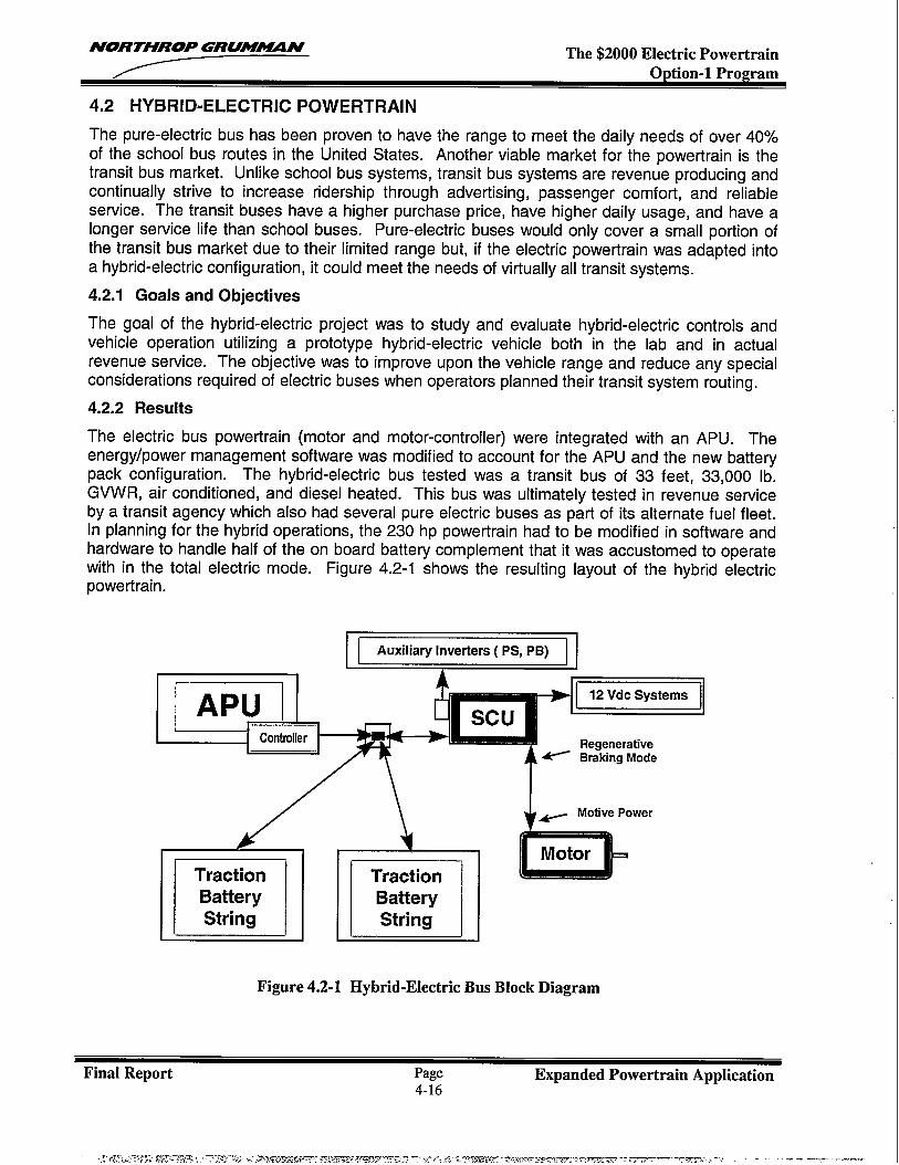
NORTHROP GRUM~N— The $2000 Electric Powertrain
4.2 HYBRID-ELECTRIC POWERTRAIN
The pure-electric bus has been proven to have the range to meet the daily needs of over 40%of the school bus routes in the United States. Another viable market for the powertrain is thetransit bus market. Unlike school bus systems, transit bus systems are revenue producing andcontinually strive to increase ridership through advertising, passenger comfort, and reliableservice. The transit buses have a higher purchase price, have higher daily usage, and have alonger service life than school buses. Pure-electric buses would only cover a small portion ofthe transit bus market due to their limited range but, if the electric powertrain was adapted intoa hybrid-electric configuration, it could meet the needs of virtually all transit systems.
4.2.1 Goals and Objectives
The goal of the hybrid-electric project was to study and evaluate hybrid-electric controls andvehicle operation utilizing a prototype hybrid-electric vehicle both in the lab and in actualrevenue service. The objective was to improve upon the vehicle range and reduce any specialconsiderations required of electric buses when operators planned their transit system routing.
4.2.2 Results
The electric bus powertrain (motor and motor-controller) were integrated with an APU. Theenergy/power management software was modified to account for the APU and the new batterypack configuration. The hybrid-electric bus tested was a transit bus of 33 feet, 33,000 lb.GVWR, air conditioned, and diesel heated. This bus was ultimately tested in revenue serviceby a transit agency which also had several pure electric buses as part of its alternate fuel fleet.In planning for the hybrid operations, the 230 hp powertrain had to be modified in software andhardware to handle half of the on board battery complement that it was accustomed to operatewith in the total electric mode. Figure 4.2-1 shows the resulting layout of the hybrid electricpowertrain.
12 Vdc Systems
Regenerative~ Braking Mode
+- Motive Power
laTractionBatteryString nTraction
BatteryString
Figure 4.2-1 Hybrid-Electric Bus Block Diagram
Final Report Page Expanded Powertrain Application4-16
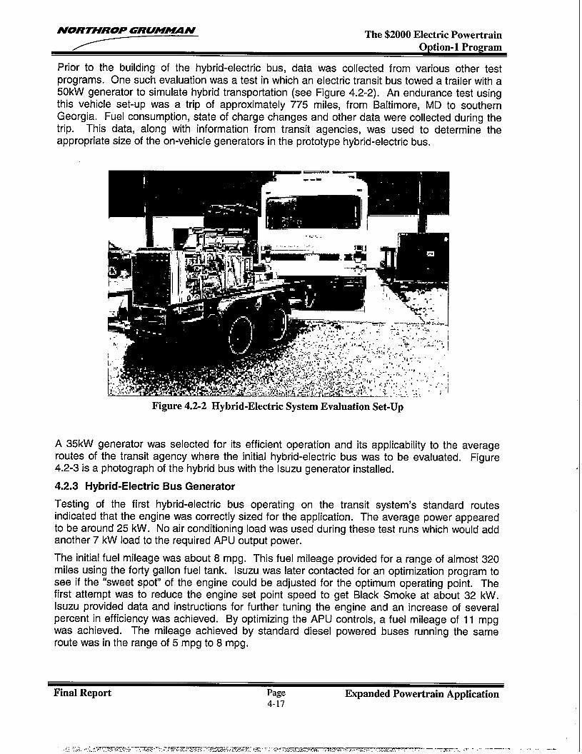
NORTHROP GRUM~N The $2000 Electric PowertrainOption-1 Program
Prior to the building of the hybrid-electric bus, data was collected from various other testprograms. One such evaluation was a test in which an electric transit bus towed a trailer with a50kW generator to simulate hybrid transportation (see Figure 4.2-2). An endurance test usingthis vehicle set-up was a trip of approximately 775 miles, from Baltimore, MD to southernGeorgia. Fuel consumption, state of charge changes and other data were collected during thetrip. This data, along with information from transit agencies, was used to determine theappropriate size of the on-vehicle generators in the prototype hybrid-electric bus.
I
Figure 4.2-2 Hybrid-Electric System Evaluation Set-Up
A 35kW generator was selected for its efficient operation and its applicability to the averageroutes of the transit agency where the initial hybrid-electric bus was to be evaluated. Figure4.2-3 is a photograph of the hybrid bus with the Isuzu generator installed.
4.2.3 Hybrid-Electric Bus Generator
Testing of the first hybrid-electric bus operating on the transit system’s standard routesindicated that the engine was correctly sized for the application. The average power appearedto be around 25 kW. No air conditioning load was used during these test runs which would addanother 7 kW load to the required APU output power.
The initial fuel mileage was about 8 mpg. This fuel mileage provided for a range of almost 320miles using the forty gallon fuel tank. Isuzu was later contacted for an optimization program tosee if the “sweet spot” of the engine could be adjusted for the optimum operating point. Thefirst attempt was to reduce the engine set point speed to get Black Smoke at about 32 kW.Isuzu provided data and instructions for further tuning the engine and an increase of severalpercent in efficiency was achieved. By optimizing the APU controls, a fuel mileage of 11 mpgwas achieved. The mileage achieved by standard diesel powered buses running the sameroute was in the range of 5 mpg to 8 mpg.
Final Report Page Expanded Powertrain Application..-4-1/
II
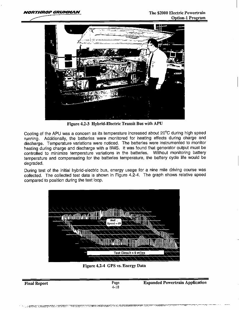
NORTHROP GRUM#4ZlN The $2000 Electric PowertrainODtion-1 Promam
Figure 4.2-3 Hybrid-Electric Transit Bus with APU
Cooling of the APU was a concern as its temperature increased about 20”C during high speedrunning. Additionally, the batteries were monitored for heating effects during charge anddischarge. Temperature variations were noticed. The batteries were instrumented to monitor
heating during charge and discharge with a BMS, It was found that generator output must becontrolled to minimize temperature variations in the batteries. Without monitoring batterytemperature and compensating for the batteries temperature, the battery cycle life would bedegraded.
During test of the initial hybrid-electric bus, energy usage for a nine mile driving course wascollected. The collected test data is shown in Figure 4.2-4, The graph shows relative speedcompared to position during the test loop.
Figure 4.2-4 GPS vs. Energy Data
Final Report Page Expanded Powertrain Application4-18
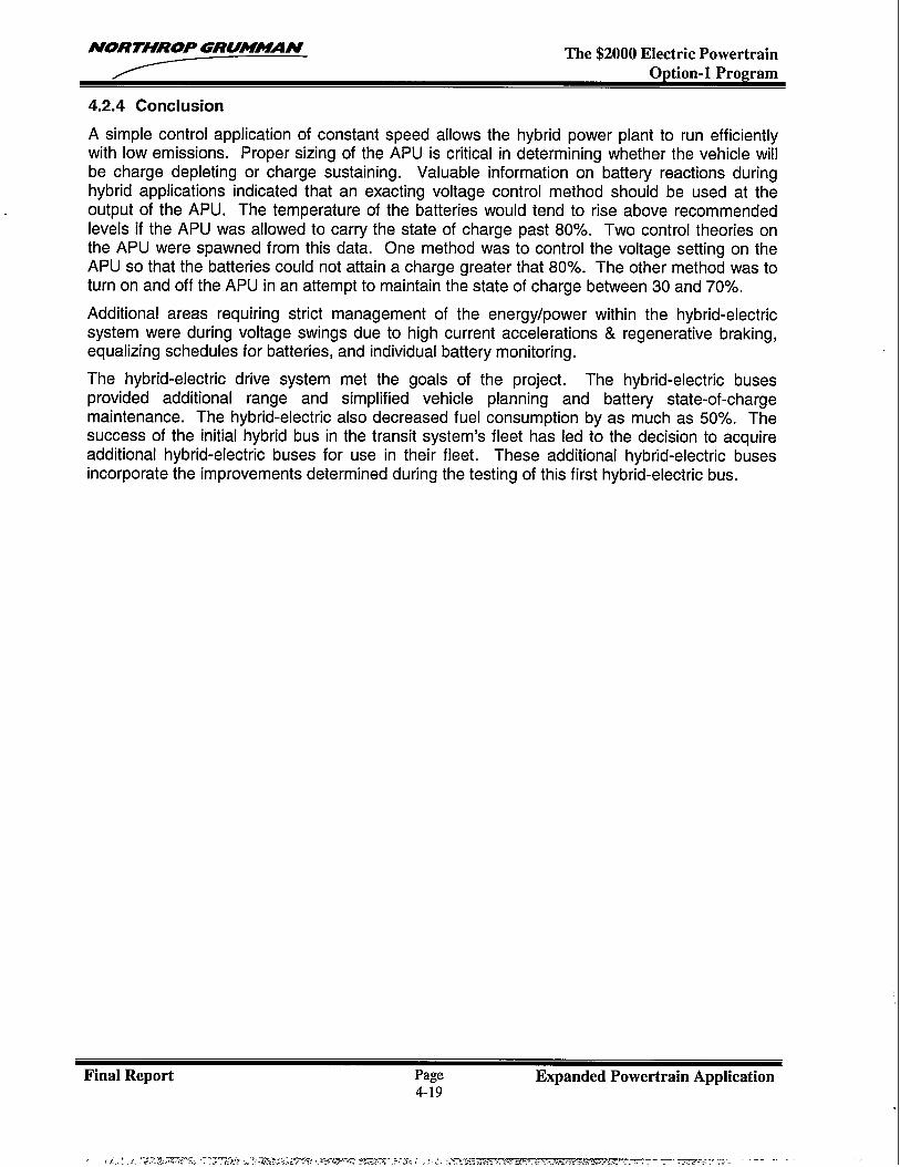
NORTHROP GRUM~N The $2000 Electric PowertrainOption-1 Program
4.2.4 Conclusion
Asimple control application of constant speed allows the hybrid power plant to run efficientlywith low emissions. Proper sizing of the APU is critical in determining whether the vehicle willbe charge depleting or charge sustaining. Valuable information on battery reactions duringhybrid applications indicated that an exacting voltage control method should be used at theoutput of the APU. The temperature of the batteries would tend to rise above recommendedlevels if the APU was allowed to carry the state of charge past 80%. Two control theories onthe APU were spawned from this data. One method was to control the voltage setting on theAPU so that the batteries could not attain a charge greater that 80Y0. The other method was toturn on and off the APU in an attempt to maintain the state of charge between 30 and 70%.
Additional areas requiring strict management of the energy/power within the hybrid-electricsystem were during voltage swings due to high current accelerations & regenerative braking,equalizing schedules for batteries, and individual battery monitoring.
The hybrid-electric drive system met the goals of the project. The hybrid-electric busesprovided additional range and simplified vehicle planning and battery state-of-chargemaintenance. The hybrid-electric also decreased fuel consumption by as much as 50Y0. Thesuccess of the initial hybrid bus in the transit system’s fleet has led to the decision to acquireadditional hybrid-electric buses for use in their fleet. These additional hybrid-electric busesincorporate the improvements determined during the testing of this first hybrid-electric bus.
Final Report Page Expanded Powertrain Application4-19

NORTHROP GRUM~N The $2000 Electric PowertrainOption-1 Program
4.3 ELECTRIC VEHICLE AUXILARY SUBSYSTEMS
With the introduction of electric powertrains, an area that seemed to be lacking with most heavyvehicle OEMS and vehicle operators was the ability to integrate and support other vehiclesystems, beyond the powertrain, that are found on electric vehicles. High voltage systems,charging systems, battery systems, and electronic systems integration were a few of the areasthat appeared to need support in order to bring electric transportation to market.
4.3.1 Goals and Objectives INorthrop Grumman’s objective for the EV sub-systems efforts performed, was to provide theengineering guidance for electric and hybrid-electric bus transportation systems. The goal ofthe effort was to have all of the system’s major components perform and support one anotherseamlessly. The intent was to improve on the transit operator’s objectives for electrictransportation and to address the clean air objectives across the United States and internationalcommunities. The vehicle system’s various major components for electric and hybrid-electrictransportation were tested at transit agencies by introducing electrically powered buses toactual revenue service. This testing was to validate the technologies from a systems operationlevel. Figure 4.3-1 shows an electric bus with the Northrop Grumman 230 HP powertrain.
Figure 4.3-1 Electric Transit Bus with 230 HP Powertrain
4.3.2 Results
System enhancements were made throughout the electric transportation system’s majorcomponents. The sub-systems analysis as well as laboratory and field testing addressedsystem level issues such as environmental conditions, the bus cooling system, the batterymanagement system, the battery energy storage system and both fast and slow charging.Summarized below are the major improvements that contributed significantly towards achievingthe goals envisioned for the electric transportation system.
Environmental ConditionsElectric and hybrid-electric buses were fielded into revenue service at various transit agenciesacross the United States. These locations provided a harsh environment of temperature
Final Report Page Expanded Powertrain Application4-20
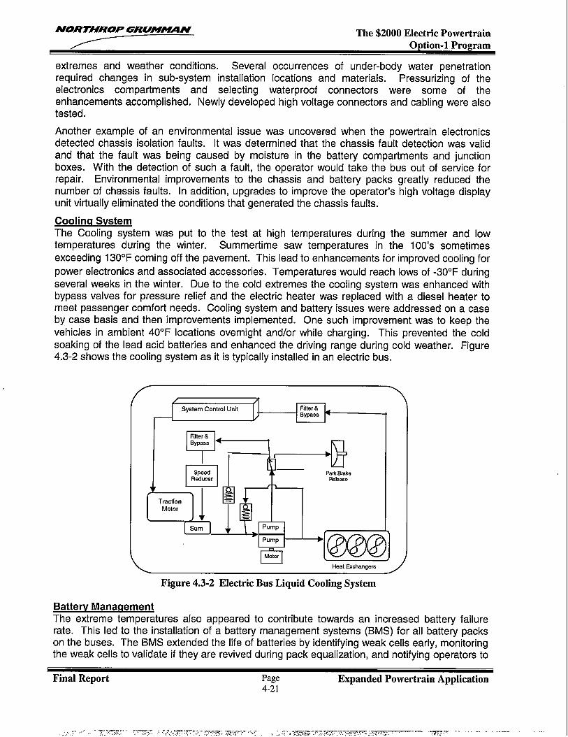
NORTHROP GRU!XUIN The $2000 Electric PowertrainOption-1 Program
extremes and weather conditions. Several occurrences of under-body water penetrationrequired changes in sub-system installation locations and materials. Pressurizing of theelectronics compartments and selecting waterproof connectors were some of theenhancements accomplished. Newly developed high voltage connectors and cabling were alsotested.
Another example of an environmental issue was uncovered when the powertrain electronicsdetected chassis isolation faults. It was determined that the chassis fault detection was validand that the fault was being caused by moisture in the battery compartments and junctionboxes. With the detection of such a fault, the operator would take the bus out of service forrepair. Environmental improvements to the chassis and battery packs greatly reduced thenumber of chassis faults. In addition, upgrades to improve the operator’s high voltage displayunit virtually eliminated the conditions that generated the chassis faults.
Coolinq SvstemThe Cooling system was put to the test at high temperatures during the summer and lowtemperatures during the winter. Summertime saw temperatures in the 100’s sometimesexceeding 130”F coming off the pavement. This lead to enhancements for improved cooling for
power electronics and associated accessories. Temperatures would reach lows of -30°F duringseveral weeks in the winter. Due to the cold extremes the cooling system was enhanced withbypass valves for pressure relief and the electric heater was replaced with a diesel heater tomeet passenger comfort needs. Cooling system and battery issues were addressed on a caseby case basis and then improvements implemented. One such improvement was to keep thevehicles in ambient 40”F locations overnight and/or while charging. This prevented the coldsoaking of the lead acid batteries and enhanced the driving range during cold weather. Figure4.3-2 shows the cooling system as it is typically installed in an electric bus.
I
K‘b‘:‘‘1Filter &Bypass
n
speed Park BrakeRaduc-?r Re!ase
Traction
I
B~
Motor
Sum
X.. m
Pump
Pump
m
Figure 4.3-2 Electric Bus Liquid Cooling System
Batterv ManagementThe extreme temperatures also appeared to contribute towards an increased battery failurerate. This led to the installation of a battery management systems (BMS) for all batte~ packson the buses. The BMS extended the life of batteries by identifying weak cells early, monitoringthe weak cells to validate if they are revived during pack equalization, and notifying operators to
Final Report Page Expanded Powertrain Application4-21
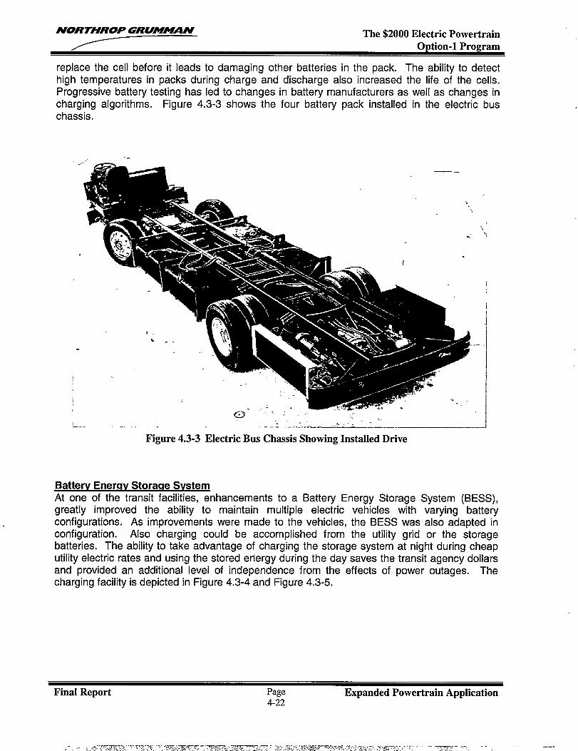
NORTHROP GRUM~N The $2000 Electric PowertrainOption-1 Program
replace the cell before it leads to damaging other batteries in the pack. The ability to detecthigh temperatures in packs during charge and discharge also increased the life of the cells.Progressive battery testing has led to changes in battery manufacturers as well as changes incharging algorithms. Figure 4.3-3 shows the four battery pack installed in the electric buschassis.
.-‘,
,.
I
a.
—
m= -.
1 -“”-,—.- ------ . .4 .’---”.- —____ ---- ,——. .
Figure 4.3-3 Electric Bus Chassis Showing Installed Drive
Batterv Energy Storaqe SvstemAt one of the transit facilities, enhancements to a Battery Energy Storage System (BESS),greatly improved the ability to maintain multiple electric vehicles with varying batteryconfigurations. As improvements were made to the vehicles, the BESS was also adapted inconfiguration. Also charging could be accomplished from the utility grid or the storagebatteries. The ability to take advantage of charging the storage system at night during cheaputility electric rates and using the stored energy during the day saves the transit agency dollarsand provided an additional level of independence from the effects of power outages. Thecharging facility is depicted in Figure 4.3-4 and Figure 4.3-5.
Final Report Page Expanded Powertrain Application4-22
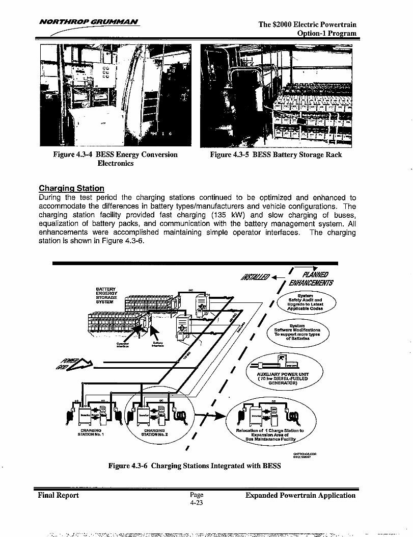
NORTHROP GRUM~N The $2000 Electric PowertrainOption-1 Program
Figure 4.3-4 BESS Energy ConversionElectronics
Charqinq StationDuring the test period the charging stations
Figure 4.3-5 BESS Battery Storage Rack
continued to be o~timized and enhanced toaccommodate the differences in battery types/manufacturers and vehicle configurations. Thecharging station facility provided fast charging (135 kW) and slow charging of buses,equalization of battery packs, and communication with the battery management system. Allenhancements were accomplished maintaining simple operator interfaces. The chargingstation is shown in Figure 4.3-6.
CiiiLL2A3z2z7+-/ &!!c15ffmY
RATTERY ./
Syst8m* Safeiy Audit and
/k~
/1/ Sv?lt.. \
.#+.,,, w, yxi-J%E%i%Jy8
—mmu Y2a97
Figure 4.3-6 Charging Stations Integrated with BESS
Final Report Page Expanded Powertrain Application4-23
NORTHROP GRUM-N The $2000 Electric PowertrainOption-1 Program
4.3.3 Conclusions
The practical application of the technologies in real life revenue service of the electrictransportation system, provided invaluable data leading to system improvements. It provided abasis for recommending improvements and product enhancements from an economical anduser-friendly point of view. The results of the testing have been a positive and have been anintegral step (in addition to the controlled “bench” or lab test environment) in bringing a newtransportation technology to market.
In summary, the use of several test sites provided valuable lessons on system performanceduring vehicle use in operational transit environments. Battery management techniques haveled to system changes to safeguard the batteries at temperature extremes. The charginginfrastructure improvements have increased the cycle life of batteries and lowered the operatingcosts of the transit agency. The BESS charging facility will be capable of handling a variety ofbatteries from different manufacturers as advances to battery technology become available andare introduced. System cooling enhancements have extended the environmental operability ofthe systems, addressing the needs of a broader customer base.
Batteries continue to appear as the sub-system having negative impact on the systemdevelopers and transit operators. Limited range has been addressed by hybrid-electricpowertrains. However most of the vehicle cost and maintenance issues are directly attributableto the poor performance of batteries when applied to electric vehicles. Batteries need to bemore reliable, longer cycle life, and considerably less expensive than they are presently.
Final Report Page Expanded Powertrain Application4-24