Embed Size (px)
Citation preview
ADDENDUM - SUGGESTED WIRING CONFIGURATION ADDENDA - SCHÉMA DE BRANCHEMENT SUGGÉRÉ
ALL REV.: 20160914ALL REV.: 20160914
ONLY COMPATIBLE WITH AUTOMATIC TRANSMISSION VEHICLES.COMPATIBLE AVEC VÉHICULE À TRANSMISSION AUTOMATIQUE SEULEMENT.
NOTES 12V BATTERY | 12V BATTERIE
ATTENTION THE T-HARNESS CURRENT IS LIMITED AT 10 AMP MAXIMUM.
If a parking lights (+) wire is use : they require more than 10Amp. Connect the remote-starter’s power directly to the vehicles battery with the appropriate fuse.
Some remote starters can not be powered through Data-Link. In these cases connect the remote starter’s fused 12V power wire directly to the T-Harness.
ATTENTION LE COURANT DU 12V PROVENANT DU HARNAIS-EN-T EST LIMITÉ À 10 AMPÈRES MAXIMUM.
Si le fil des lumières de stationnement (+) est utilisé: il requière plus de 10 Ampères, branchez le 12V du démarreur à distance directement à la batterie du véhicule avec le fusible approprié.
Certains démarreurs à distance NE peuvent PAS être allimentés par le Data-Link. Dans ce cas, branchez le 12V (avec fusible) du démarreur à distance directement au harnais-en-T.
Vehicle functions supported in this diagram (functional if equipped) | Fonctions du véhicule supportées dans ce diagramme (fonctionnelles si équipé)
VEHICLEVEHICULES
YEARS ANNÉES Im
mob
ilize
r byp
ass
Lock
Unl
ock
Arm
Dis
arm
Hat
ch (o
pen)
Trun
k (o
pen)
Slid
ing
Doo
r
Tach
omet
er
Doo
r Sta
tus
Trun
k S
tatu
s
Han
d-B
rake
Sta
tus
Foot
-Bra
ke S
tatu
s
OEM
Rem
ote
mon
itorin
g
CHRYSLER300-300C 2008-2010 • • • • • • • • • •Town & Country 2008-2014 • • • • • • • • • • • • •DODGEChallenger 2008-2014 • • • • • • • • • • • •Charger 2008-2010 • • • • • • • • • •Durango 2011-2012 • • • • • • • • • • • •Grand Caravan 2008-2014 • • • • • • • • • • • • •Journey 2009-2010 • • • • • • • • • • • •Magnum 2008 • • • • • • • • • • • • •RAM 2009-2012 • • • • • • • • • •JEEPCommander 2008-2011 • • • • • • • • • • • •Grand Cherokee 2008-2013 • • • • • • • • • • • •
Push-to-Start 2011-2013 • • • • • • • • • • • •VOLKSWAGENRoutan 2009-2013 • • • • • • • • • • • • •
Guide # 46671
HARDWARE VERSIONVERSION MATÉRIELLE
FIRMWARE VERSIONVERSION LOGICIELLE This manual may change without notice.
www.fortinbypass.com for latest version.Ce Guide peut faire l’objet de changement
sans préavis. www.fortinbypass.com pour la récente version.
MINIMUM 6 74.[25]CHRYSLER/DODGE/JEEP/MITSUBISHI MINIMUM
THAR-CHR4
Page 1 / 6
THARNESS STAND ALONE INSTALLATION INSTALLATION HARNAIS STAND ALONE
This guide may change without notice. See www.fortin.ca for latest version.Ce guide peut faire l’objet de changement sans préavis. Voir www.fortin.ca pour la récente version.
PARTS REQUIRED (NOT INCLUDED) | PIÈCES REQUISES (NON INCLUSES)
STAND ALONE CONFIGURATION | CONFIGURATION EN DÉMARREUR AUTONOME
FLASH LINKUPDATER 2
FLASH LINK MANAGER
OFF
ON
SOFTWARE | PROGRAMME
Microsoft Windows Computer(Internet connection required)Ordinateur Microsoft Windows(Connection Internet requise)
HOOD PIN
VALET SWITCHCOMMUTATEUR VALET
REMOTE START SAFETY OVERRIDE SWITCH
CONTACTDECAPOT
COMMUTATEUR DE SÉCURITÉ DE DÉSACTIVATION DU DÉMARREUR À DISTANCE
MANDATORY | OBLIGATOIRENotice: the installation of safety elements are mandatory.The hood pin and the valet switch are essential security elements and must be installed.
Notice: l'installation des éléments de sécurité est obligatoire.Le contact de capot et le commutateur de valet sont des éléments de sécurité essentiels et doivent absolument être installés.
Part #: RSPB availbale, Sold separately.Pièce #: RSPB disponible, vendu séparément.
Program bypass option:Programmez l’option du contournement:
UNIT OPTIONOPTION UNITE DESCRIPTION
D1OEM Remote Stand Alone Remote StarterDémarreur à distance Autonome avec télécommande d’origine
UNIT OPTIONOPTION UNITE DESCRIPTION
D4Hybrid mode (Vehicle hybrid only)Mode hybride (vehicule hybride seulement)
Program bypass option with oem remote:Programmez l’option du contournement
avec télécommande d'origine:
UNIT OPTIONOPTION UNITE DESCRIPTION
C1OEM Remote Monitoring
Supervision de la télécommande d'origine
Program bypass option with RF KIT antenna:Programmez l’option du contournement
avec antenne RF:
Program bypass optionVehicle hybrid only:
Programmez l’option du contournementvehicule hybride seulement:
UNIT OPTIONOPTION UNITE DESCRIPTION
H1 to H6H1 à H6
Supported RF Kitsand select RF KitKit RF supportéset sélectionnez le KIT RF
All doors must be closed.
Toutes les portes doivent être fermées
Brake ON No tach Ignition before start
Hood Open
Frein ActivéPas de TachClé de contact détectée avant démarrage Capot Ouvert
REMOTE STARTER DIAGNOSTICSDIAGNOSTIQUE DU DÉMARREUR À DISTANCEMODULE RED LED | DEL ROUGE DU MODULEx2 �ash : x3 �ash : x4 �ash :
x5 �ash :
The vehicle will START.
Le véhicule DÉMARRE.
START3XPress the OEM remote’s Lock button 3x to remote-start (or remote-stop) the vehicle.
Appuyez sur le bouton Verrouillage 3X de la télécommande d'origine pour démarrer à distance (ou
arrêter à distance) le véhicule.
REMOTE STARTER FUNCTIONNALITY | FONCTIONNALITÉS DU DÉMARREUR À DISTANCE
REMOTE STARTER WARNING CARD | CARTE D'AVERTISSEMENT DE DÉMARREUR À DISTANCE
CUT THIS WARNING CARD AND STICK IT ON A VISIBLE PLACE:or use the package RSPB, Sold separately.
COUPEZ CETTE CARTE D'AVERTISSEMENT ET COLLEZ-LA À UN ENDROIT VISIBLE:ou utilisez la trousse RSPB, vendue séparément.
THE VEHICLE CAN BE STARTED BY EITHER: PRESSING THE LOCK BUTTON
ON THE OEM REMOTE 3 TIMES CONSECUTIVELY OR BY A
SMARTPHONE. TURN ON THE SAFETY SWITCH LOCATED UNDER THE
DASHBOARD BEFORE WORKING ON THE VEHICLE.
LE VÉHICULE PEUT DÉMARRER SOIT: EN APPUYANT 3 FOIS CONSÉCUTIVEMENT SUR
LE BOUTON VERROUILLAGE DE LA TÉLÉCOMMANDE DU VÉHICULE OU PAR UN TÉLÉPHONE INTELLIGENT. ACTIONNEZ EN
POSITION ‘ON’ LE COMMUTATEUR DE SÉCURITÉ SITUÉ SOUS LE TABLEAU DE BORD
AVANT LES TRAVAUX D'ENTRETIEN.
DÉMARREUR À DISTANCEREMOTE STARTER
WARNING | ATTENTION
Page 2 / 6

This guide may change without notice. See www.fortin.ca for latest version.Ce guide peut faire l’objet de changement sans préavis. Voir www.fortin.ca pour la récente version.
DESCRIPTION | DESCRIPTION
VEHICLE FIT GUIDE GUIDE DES VÉHICULES
CHRYSLER A B C D E F G H I J K L M N P Q R S T U V W X
300-300C 2008-2010 • • • • • • • • •Town & Country 2008-2014 • • • • • • • • • • •
DODGE A B C D E F G H I J K L M N P Q R S T U V W X
Challenger 2008-2014 • • • • • • • • • • •Charger 2008-2010 • • • • • • • • •Durango 2011-2012 • • • • • • • • • •Grand Caravan 2008-2015 • • • • • • • • • • •Journey 2009-2010 • • • • • • • • • •
RAM 2009-2012 • • • • • • • • •
JEEP A B C D E F G H I J K L M N P Q R S T U V W X
Commander 2008-2011 • • • • • • • • • •Grand Cherokee 2008-2013 • • • • • • • • • •
Push-to-Start 2011-2013 • • • • • • • • • •
VOLKSWAGEN A B C D E F G H I J K L M N P Q R S T U V W X
Routan 2008-2012 • • • • • • • • • •
Page 3
VEHICLE | VEHICULES
YEARS
ANNÉES Lock
Un
lock
Arm
Dis
arm
Hat
ch(o
pen
)
Tru
nk
(op
en)
Slid
ing
Do
or
Win
do
wR
oll
Do
wn
Gas
Do
or
RA
PD
isab
le
Par
kin
gLi
ght
Mem
ory
Dri
ver
Tach
om
eter
Hea
ted
Seat
s
Hea
ted
Mir
rors
Rea
rD
efro
st
Do
or
Stat
us
Tru
nk
Stat
us
Ho
od
Stat
us
Han
d-B
rake
Stat
us
Foo
t-B
rake
Stat
us
Tran
spo
nd
erB
ypas
s
PK
3,
Pas
slo
ck
VEHICLE FUNCTIONALITY (IF EQUIPPED)FONCTIONS S’APPLIQUENT SI LE VÉHICULE EN EST ÉQUIPÉ
With
Da
ta-L
ink
Ave
c D
ata
-Lin
k
With
ou
t D
ata
-Lin
kS
an
s D
ata
-Lin
k
Déterminez si le démarreur à distance ou système d'alarme est compatible en Data-Link 2-voies.
Determine if the remote-starter or alarm system supports 2-way Data-Link.
CONNECTION
PROCÉDURE DE PROGRAMMATION DU EVO-ALL
EVO-ALL PROGRAMMING PROCEDURE
See Page 7
A B
A B
A BA BA BA BA B
A B
A B
A BA B
A B
•
•••
•••
•
WIRECOLOR COULEURS DE FIL
CHRYSLER300-300C
Town & Country
DODGEChallengerChargerDurangoGrand CaravanJourneyRAM
JEEPCommander
Grand Cherokee
Grand Cherokee Push-to-Start
VOLKSWAGENRoutan
PARKING LIGHT
PARKING LIGHT
PARKING LIGHT
PARKING LIGHT
(-)PARKING LIGHT WHITE/BROWN LIGHT SWITCH HARNESS 2K OHM RESISTORPARKING
(-)PARKING LIGHT WHITE/BROWN PARKING LIGHT HARNESS 1K OHM RESISTOR
(-)PARKING LIGHT WHITE/BROWN LIGHT SWITCH HARNESS 2K OHM RESISTOR PARKING (-)PARKING LIGHT WHITE/BROWN PARKING LIGHT HARNESS 1K OHM RESISTOR
(-)PARKING LIGHT PINK/RED PARKING LIGHT HARNESS 1.5K OHM RESISTOR (-)PARKING LIGHT WHITE/GREEN PARKING LIGHT HARNESS 1K OHM RESISTOR (+)PARKING LIGHT WHITE/PURPLE PASSENGER RUNNING BOARD HARNESS (-)PARKING LIGHT WHITE PARKING LIGHT HARNESS 1K OHM RESISTOR
(-)PARKING LIGHT RELAY CENTER UNDER HOOD
(+)PARKING LIGHT WHITE/TAN DRIVER KICK PANEL (+)PARKING LIGHT WHITE/TAN DRIVER KICK PANEL
(+)PARKING LIGHT RED AND OPEN GREY/RED
WITH DATA-LINKAVEC DATA-LlNK
In order to utilize this type of connection the remote-starter or alarm-system must be compatible with the Fortin Data-link protocol. Consult the installation guide or visit www.fortinbypass.com/datalink/ for more information.Le démarreur à distance ou le système d'alarme doit être compatible avec le protocole Data-link Fortin pour ces branchements. Consultez le guide d'installation du démarreur à distance ou du système d'alarme ou visitez le www.fortinbypass.com/datalink/ pour plus d'informations.
For all other remote-starters or alarm-systems perform the following connections.Pour tout autres types de démarreurs à distance ou d ' a l a r m e , e f f e c t u e z l e s branchements suivants.
WITH OUT DATA-LINKSANS DATA-LlNK
A remote car starter installation can be completed using only the interface module. An after-market remote car starter not required. Automatic transmission onlyUn installation de démarreur à distance peut être complété avec seulement ce module. Pas de démarreur à distance nécessaire. Transmission automatique seulement.
STAND ALONEDÉMARREUR AUTONOME
Sta
nd
alo
ne
dé
ma
rre
ur
au
ton
om
e
C
C
CCCCC
C
C
CC
C
ALLE O ALL
Pick-Up 2010-2012 • • • • • • • • •A B C
LE TABLEAU EST DANS INDESIGN
Page 3 / 6
This guide may change without notice. See www.fortin.ca for latest version.Ce guide peut faire l’objet de changement sans préavis. Voir www.fortin.ca pour la récente version.
Yellow In A1Purple In A2
Purple/White In A3Green Out A4White Out A5
Orange In A6Orange/Black In A7
Dk.Blue In A8Red/Blue In A9
Lt.Blue/Black A10Black Out A11
Pink Out A12Yellow/Black In A13Brown/White Out A14
Pink/Black Out A15Purple/Yellow A16
Green/White A17Green/Red A18
White/Black A19Lt.Blue A20
C5 BrownC4 Gray/Black C3 GrayC2 Orange/BrownC1 Orange/Green
D6 White/RedD5 White/BlueD4 White/GreenD3 Yellow/RedD2 Yellow/BlueD1 Yellow/Green
A C
D
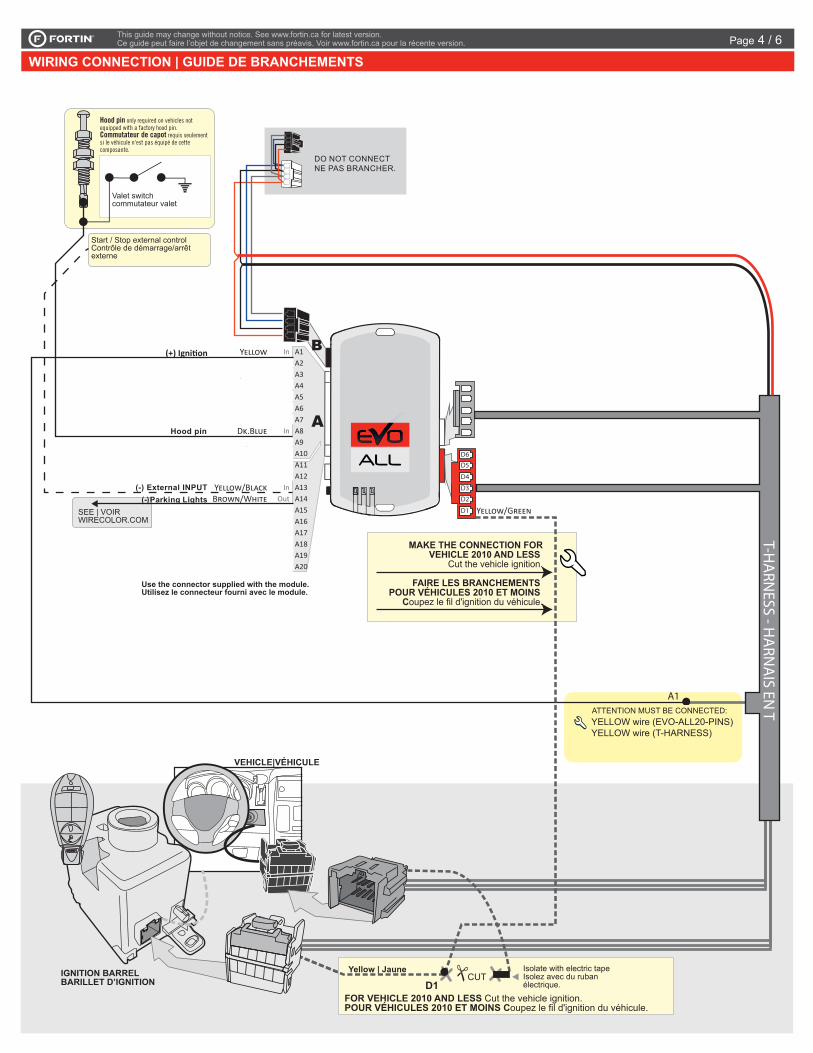
WIRING CONNECTION | GUIDE DE BRANCHEMENTS
ATTENTION MUST BE CONNECTED:
Yellow | Jaune CUTD1Yellow | Jaune CUT
D1Isolate with electric tapeIsolez avec du ruban électrique.
FOR VEHICLE 2010 AND LESS Cut the vehicle ignition.POUR VÉHICULES 2010 ET MOINS Coupez le fil d'ignition du véhicule.
MAKE THE CONNECTION FORVEHICLE 2010 AND LESS
Cut the vehicle ignition.
FAIRE LES BRANCHEMENTS POUR VÉHICULES 2010 ET MOINS
Coupez le fil d'ignition du véhicule.
VEHICLE|VÉHICULE
IGNITION BARRELBARILLET D’IGNITION
Use the connector supplied with the module.Utilisez le connecteur fourni avec le module.
(+) Ignition
T-HA
RNESS - H
ARN
AIS EN
T
D6
D5
A1
D4
D3
D2
D1
Valet switchcommutateur valet
Hood pin only required on vehicles not equipped with a factory hood pin.Commutateur de capot requis seulement si le véhicule n'est pas équipé de cette composante.
DO NOT CONNECTNE PAS BRANCHER.
Start / Stop external controlContrôle de démarrage/arrêt externe
B
SEE | VOIRWIRECOLOR.COM
Pa
Hood pin
(-) External INPUTrking Lights(-)
YELLOW wire (EVO-ALL20-PINS)YELLOW wire (T-HARNESS)
Page 4 / 6
This guide may change without notice. See www.fortin.ca for latest version.Ce guide peut faire l’objet de changement sans préavis. Voir www.fortin.ca pour la récente version.
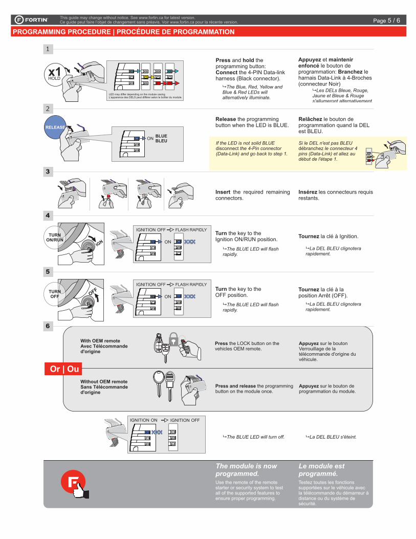
PROGRAMMING PROCEDURE | PROCÉDURE DE PROGRAMMATIONPage 5 / 6
ALL
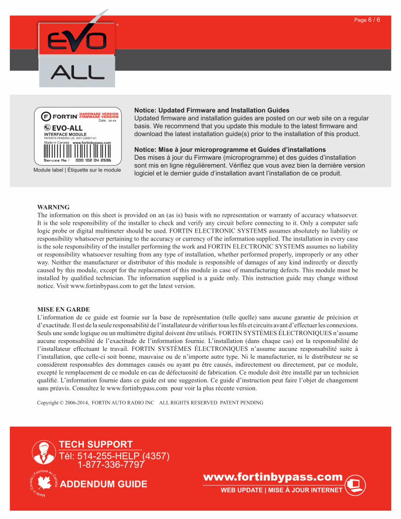
Service No : 000 102 04 2536
Date: xx-xx
INTERFACE MODULE
Made in CanadaPATENTS PENDING US: 2007-228827-A1
www.fortinbypass.com
HARDWARE VERSION FIRMWARE VERSION
Module label | Étiquette sur le module
Notice: Updated Firmware and Installation GuidesUpdated fi rmware and installation guides are posted on our web site on a regular basis. We recommend that you update this module to the latest fi rmware and download the latest installation guide(s) prior to the installation of this product.
Notice: Mise à jour microprogramme et Guides d’installationsDes mises à jour du Firmware (microprogramme) et des guides d’installation sont mis en ligne régulièrement. Vérifi ez que vous avez bien la dernière version logiciel et le dernier guide d’installation avant l’installation de ce produit.
WARNINGThe information on this sheet is provided on an (as is) basis with no representation or warranty of accuracy whatsoever. It is the sole responsibility of the installer to check and verify any circuit before connecting to it. Only a computer safe logic probe or digital multimeter should be used. FORTIN ELECTRONIC SYSTEMS assumes absolutely no liability or responsibility whatsoever pertaining to the accuracy or currency of the information supplied. The installation in every case is the sole responsibility of the installer performing the work and FORTIN ELECTRONIC SYSTEMS assumes no liability or responsibility whatsoever resulting from any type of installation, whether performed properly, improperly or any other way. Neither the manufacturer or distributor of this module is responsible of damages of any kind indirectly or directly caused by this module, except for the replacement of this module in case of manufacturing defects. This module must be installed by qualifi ed technician. The information supplied is a guide only. This instruction guide may change without notice. Visit www.fortinbypass.com to get the latest version.
MISE EN GARDE L’information de ce guide est fournie sur la base de représentation (telle quelle) sans aucune garantie de précision et d’exactitude. Il est de la seule responsabilité de l’installateur de vérifi er tous les fi ls et circuits avant d’effectuer les connexions. Seuls une sonde logique ou un multimètre digital doivent être utilisés. FORTIN SYSTÈMES ÉLECTRONIQUES n’assume aucune responsabilité de l’exactitude de l’information fournie. L’installation (dans chaque cas) est la responsabilité de l’installateur effectuant le travail. FORTIN SYSTÈMES ÉLECTRONIQUES n’assume aucune responsabilité suite à l’installation, que celle-ci soit bonne, mauvaise ou de n’importe autre type. Ni le manufacturier, ni le distributeur ne se considèrent responsables des dommages causés ou ayant pu être causés, indirectement ou directement, par ce module, excepté le remplacement de ce module en cas de défectuosité de fabrication. Ce module doit être installé par un technicien qualifi é. L’information fournie dans ce guide est une suggestion. Ce guide d’instruction peut faire l’objet de changement sans préavis. Consultez le www.fortinbypass.com pour voir la plus récente version.
Copyright © 2006-2014, FORTIN AUTO RADIO INC ALL RIGHTS RESERVED PATENT PENDING
TECH SUPPORTTél: 514-255-HELP (4357) 1-877-336-7797
ADDENDUM GUIDEWEB UPDATE | MISE À JOUR INTERNET
www.fortinbypass.com
EVO-ALL
Page 6 / 6
![ReiningintheOutliersinMap-ReduceClustersusingMantri · 2019. 2. 25. · ily due to reduce operations that are neither commuta-tive nor associative [28], for instance, a reduce that](https://img.pdfslide.us/doc/110x75/5fecb45dcd09f45bce7244af/reiningintheoutliersinmap-reduceclustersusingmantri-2019-2-25-ily-due-to-reduce.jpg)