Embed Size (px)
Citation preview
Thailand Water Supply System Project
By:Stephen Bonk (Team Leader)
Kevin DischinoJoseph Moore

Preliminary Site Assessment
Village of Hantham: subset of Longkhot, Thailand
Inadequate water supply during the dry season159 Households and 453 PeopleAverage Water Usage: 200 L/day per HouseholdGathered Survey DataCollected Soil SampleDetermined available resources

Survey Data

Design Goals
Supply entire village Sustainably powered pumping systemEasily maintained and constructible Storage
SystemDistribution SystemO & M ManualExtremely Economical

Water Resources and Hydraulics Design

Water Usage
Average Annual Water Usage is 200 L/day per Household
Total Village Usage is 1,123 cf/dayTotal Tank Volume for 3 day supply = 3,369 cfMaximum Hourly Flow per Year is 270% of
Average Flow per Year Maximum Hourly Flow per Year = 0.0351 cfs

Minimum Storage Tank Elevation
Must provide adequate water pressure for highest household in the village
Is structure required to provide additional elevation?

Minimum Storage Tank Elevation

Minimum Storage Tank Elevation

Minimum Storage Tank Elevation
Major Head Loss in Pipe A: 1 in Diameter Major Head Loss = 323.5 ft
2 in Diameter Major Head Loss = 11.7 ft
3 in Diameter Major Head Loss = 1.7 ft
Minimum Diameter of Pipe A for Maximum Velocity of 10 fps = 0.8 in
3 in Diameter Pipe Selected
Minimum Storage Tank Elevation
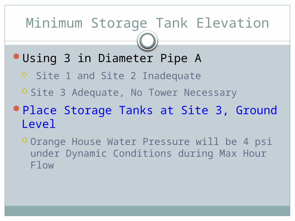
Using 3 in Diameter Pipe A Site 1 and Site 2 Inadequate
Site 3 Adequate, No Tower Necessary
Place Storage Tanks at Site 3, Ground Level Orange House Water Pressure will be 4 psi under
Dynamic Conditions during Max Hour Flow

Pumping System
Submersible Pump Pusher PumpSystem Energy

Pumping System
0.0 5.0 10.0 15.0 20.0 25.00.00
100.00
200.00
300.00
400.00
500.00
600.00
700.00
800.00
1 in Pipe System Head Curve
Flow (gpm)
Head (
ft)
Pump System
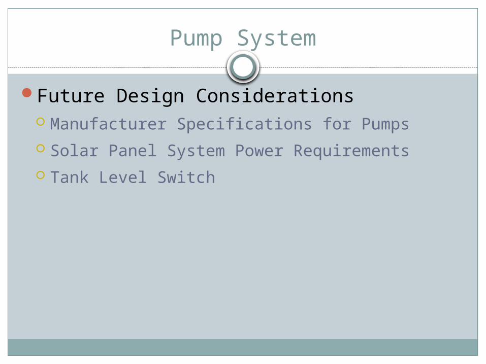
Future Design Considerations Manufacturer Specifications for Pumps Solar Panel System Power Requirements Tank Level Switch

Water Distribution System Design

Site View
Process
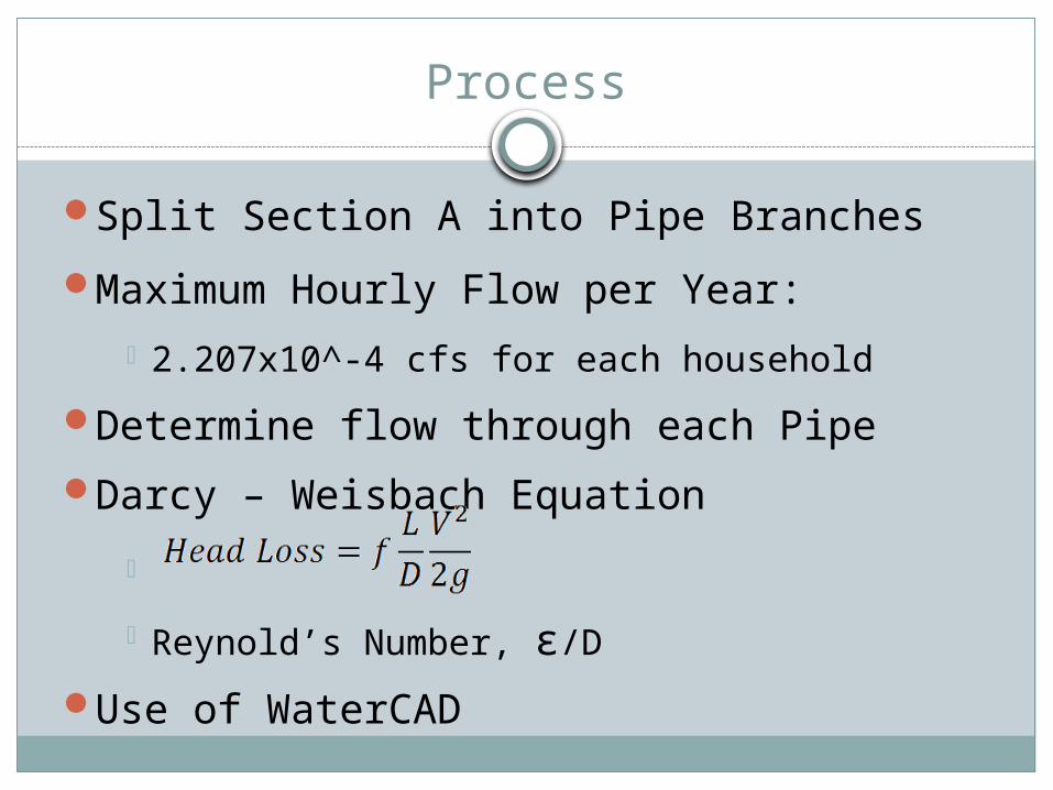
Split Section A into Pipe Branches
Maximum Hourly Flow per Year:
2.207x10^-4 cfs for each household
Determine flow through each Pipe
Darcy – Weisbach Equation
Reynold’s Number, ε/D
Use of WaterCAD

Section A Schematic
Pipe 3200 ft.
Pipe 2320 ft.
Pipe 1 445 ft.
Pipe 4 = 200 ft.
Pipe 5350 ft.
Pipe 6250 ft.
Pipe 7 = 275 ft.

Design of Pipe 1
Assume Maximum Velocity between 10-20ft/s
Find Minimum Diameter needed (A = Q/V) For Pipe 1 of 13Q:
Diameter = 0.16” – 0.23”
For 0.25” Diameter Head Loss = 658 feet (Too Large)
For 1” Diameter – Head Loss = 0.98 feet For 2” Diameter – Head Loss = 0.0242 feet
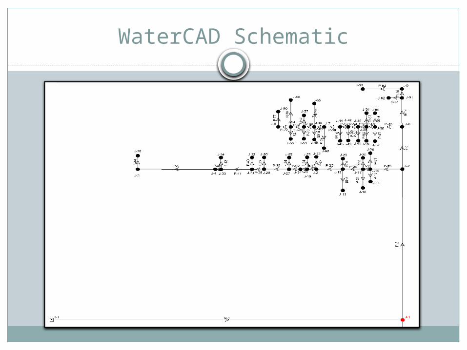
WaterCAD Schematic

Input / Output

Total Head Loss
Hand Calculations 1” Diameter – 3.025 feet 2” Diameter – 0.079 feet
WaterCAD Results 2” Diameter – 0.0665 ft.

WaterCAD Output
PipeStart Node
Stop Node
Diameter (in) Material
Flow (cfs)
Headloss Gradient (ft/ft) Length (ft)
Headloss (ft)
P-1 T-1 J-1 3 PVC0.03509
1 0.000867 1,903 1.649901
P-2 J-1 J-2 4 PVC0.00662
1 0.000008 853 0.006824
P-5 J-4 J-5 2 PVC0.00022
1 0.000004 200 0.0008
P-6 J-2 J-6 2 PVC0.00375
2 0.000083 200 0.0166
P-13 J-2 J-10 2 PVC0.00286
9 0.000052 150 0.0078
P-15 J-10 J-11 0.75 PVC0.00022
1 0.000198 25 0.00495
P-18 J-12 J-13 0.75 PVC0.00022
1 0.000198 100 0.0198
P-19 J-10 J-17 2 PVC0.00242
8 0.000046 30 0.00138
P-20 J-17 J-12 2 PVC0.00198
6 0.000036 85 0.00306
P-21 J-17 J-18 0.75 PVC0.00022
1 0.000198 80 0.01584
P-23 J-19 J-3 2 PVC0.00110
4 0.00002 25 0.0005
P-24 J-19 J-20 0.75 PVC0.00022
1 0.000202 25 0.00505
P-25 J-12 J-21 2 PVC0.00154
5 0.000028 115 0.00322
P-26 J-21 J-19 2 PVC0.00132
4 0.000024 40 0.00096

Geotechnical and Storage Tank Design

Foundation
Soil Profile γ=105 pcf φ = 30o c = 0 psf (Normally
Consolidated Soil)
Soil Classification USCS: Silty or Clayey Sand
Minimum soil characteristics γ= 80 pcf φ= 28o c = 0 psf
Bearing capacity: Min=3855.9 psf, Estimated=13062.84 psf
Factor of Safety: Estimated=16.09, Min=4.75

Soil Properties
0.599 0.422 0.251 0.104 0.0750.00%
10.00%
20.00%
30.00%
40.00%
50.00%
60.00%
70.00%
80.00%
90.00%
100.00%
Sieve Analysis
Sieve Size (mm)
Perc
ent
Fin
er
(%)

Foundation Spreadsheet
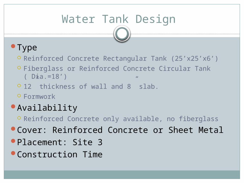
Water Tank Design
Type Reinforced Concrete Rectangular Tank (25’x25’x6’) Fiberglass or Reinforced Concrete Circular Tank
( Dia.=18’) 12” thickness of wall and 8” slab. Formwork
Availability Reinforced Concrete only available, no fiberglass
Cover: Reinforced Concrete or Sheet MetalPlacement: Site 3Construction Time
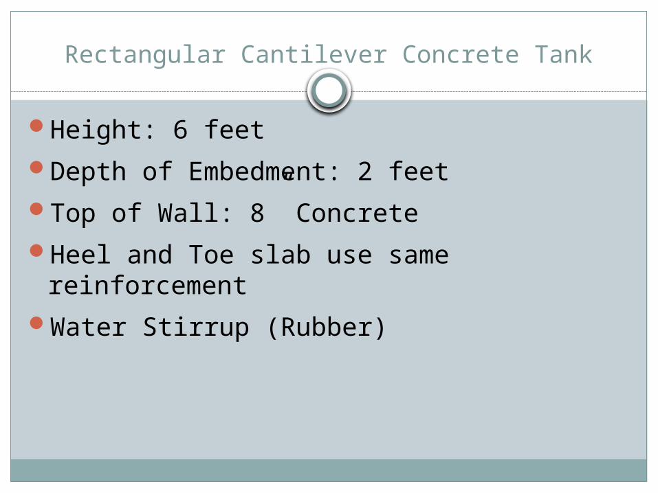
Rectangular Cantilever Concrete Tank
Height: 6 feetDepth of Embedment: 2 feetTop of Wall: 8” ConcreteHeel and Toe slab use same reinforcementWater Stirrup (Rubber)

Rectangular Cantilever Storage Tank
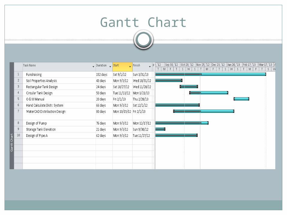
Gantt Chart

Budget

Questions?