Embed Size (px)
Citation preview

TGE is a dedicated designed series ofthermostatic expansion valves for all standardrefrigerants.The tight design meets the environmental demands for today and future.Versions for non standard refrigerants can beproduced to order.
Applications
• Water chillers• Bus A/C• Rooftop units• Heat pumps• Refrigerated containers• Others A/C and refrigeration system
Features • Refrigerants: R410A, R32, R452B, R454B, R22, R134a, R1234ze, R407F, R407A, R404A, R507, R407C and R290
• Capacity range: 3.5 – 52 TR / 12 – 182 kW for R410A
• Balance port design• Biflow with expansion in both directions• Low hysteresis• Long lifetime for heat pump applications• Mechanical connections types solder ODF,
flare, MIO, ORFS are available• Laser welded, stainless steel power element,
capillary tube, and bulb
• MOP (Max. Operating Pressure) function is available
• Optional bleed function• PS / MWP (maximum working pressure):
46 bar/ 667 psig• Straightway flow• Adjustable superheat setting• Cylindrical bulb and patented bulb strap
design• Compliance with ATEX hazard zone 2• UL certified
Data sheet
Thermostatic expansion valves Type TGE 10, TGE 20 and TGE 40
DKRCC.PD.AXV.3A.02 | 1© Danfoss | DCS (az) | 2019.01
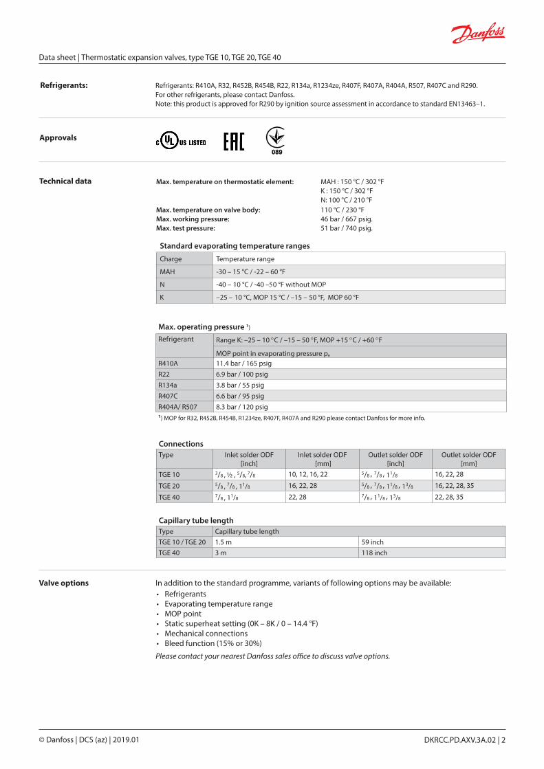
Valve options In addition to the standard programme, variants of following options may be available:• Refrigerants • Evaporating temperature range • MOP point• Static superheat setting (0K – 8K / 0 – 14.4 °F)• Mechanical connections• Bleed function (15% or 30%)
Please contact your nearest Danfoss sales office to discuss valve options.
Technical data
ConnectionsType Inlet solder ODF
[inch]Inlet solder ODF
[mm]Outlet solder ODF
[inch]Outlet solder ODF
[mm]
TGE 10 3/8 , ½ , 5/8, 7/8 10, 12, 16, 22 5/8 , 7/8 , 11/8 16, 22, 28
TGE 20 5/8 , 7/8 , 11/8 16, 22, 28 5/8 , 7/8 , 11/8 , 13/8 16, 22, 28, 35
TGE 40 7/8 , 11/8 22, 28 7/8 , 11/8 , 13/8 22, 28, 35
Capillary tube lengthType Capillary tube lengthTGE 10 / TGE 20 1.5 m 59 inchTGE 40 3 m 118 inch
Standard evaporating temperature ranges
Charge Temperature range
MAH -30 – 15 °C / -22 – 60 °F
N -40 – 10 °C / -40 –50 °F without MOP
K –25 – 10 °C, MOP 15 °C / –15 – 50 °F, MOP 60 °F
Max. operating pressure 1)
Refrigerant Range K: –25 – 10 °C / –15 – 50 °F, MOP +15 °C / +60 °F
MOP point in evaporating pressure pe
R410A 11.4 bar / 165 psigR22 6.9 bar / 100 psigR134a 3.8 bar / 55 psigR407C 6.6 bar / 95 psigR404A/ R507 8.3 bar / 120 psig1) MOP for R32, R452B, R454B, R1234ze, R407F, R407A and R290 please contact Danfoss for more info.
Refrigerants: Refrigerants: R410A, R32, R452B, R454B, R22, R134a, R1234ze, R407F, R407A, R404A, R507, R407C and R290. For other refrigerants, please contact Danfoss. Note: this product is approved for R290 by ignition source assessment in accordance to standard EN13463–1.
Approvals
Max. temperature on thermostatic element: MAH : 150 °C / 302 °F K : 150 °C / 302 °F N: 100 °C / 210 °FMax. temperature on valve body: 110 °C / 230 °FMax. working pressure: 46 bar / 667 psig.Max. test pressure: 51 bar / 740 psig.
Data sheet | Thermostatic expansion valves, type TGE 10, TGE 20, TGE 40
© Danfoss | DCS (az) | 2019.01 DKRCC.PD.AXV.3A.02 | 2

Design and function
The central push pin is fitted with a robust seal (Pos 4) that ensures maximum tightness for the life of the valve.Static superheat (SS) can be adjusted by the setting spindle (Pos 6), see fig. 1. The standard superheat setting (SS) is 4K / 7.2 °F and adjustable for 0 – 8K / 0 – 14.4 °F.
SS = Static SuperheatOS = Opening SuperheatSH = SS + OS = total superheat
Example:Static superheat SS = 4K / 7.2 °FOpening superheat OS = 4K / 7.2 °FThe opening superheat is 4K / 7.2 °F, i.e. from the point the valve begins to open up to rated capacity. Opening superheat is determined by the design and cannot be changed.Total superheat SH = SS + OS SH = 4 + 4 = 8K / 14.4 °FTotal superheat SH can be altered by changing SS (by using the setting spindle). Fig. 3
Balanced port design and advantageThe TGE series of thermostatic expansion valves have balanced port design.Balanced port design prevents changes in pressure drop across the valve from influencing operation and provides excellent control on applications having widely varying operating conditions.Balanced port TXV’s are recommended in refrigeration and air conditioning systems with any combi-nations of these conditions:
1) Widely varying head pressures2) Widely varying evaporator loads3) Widely varying pressure drop across the TXV4) Fluctuating or extremely low liquid temperatures5) Intermittent liquid line flash gas
TGE valves are designed for biflow operations. TGE 10 has minor capacity reduction in reverse flow.
Danfoss67N47.10
1. Bulb with capillary tube2. Thermostatic element3. Thrust pad4. Push pin seal5. Cone6. Valve body7. Static SH adjustment spindle8. Protective cap
Fig. 1Balanced port designTGE 10
Fig. 2Double balanced port designTGE 20 and TGE 40
1 1
2 2
3 3
4 4
5 5
6 6
7 7
88
Data sheet | Thermostatic expansion valves, type TGE 10, TGE 20, TGE 40
© Danfoss | DCS (az) | 2019.01 DKRCC.PD.AXV.3A.02 | 3

Dan
foss
67N
13.1
2D
anfo
ss67
N27
.11
Application
Fig. 6 Simplified heat pump system
TGE
EVR
SGI/SGN DCL/DML
Fig. 4Traditional refrigeration plant
Indoor coil Outdoor coil
Outdoor coil
TGETGE
SGI/SGN
Fig. 5Conventional system with summer/winter operation
DCB/DMB
Fig. 4 A diagram of a traditional refrigeration plant where TGE is used for flow in one direction only.
TGE
Indoor coil
Outdoor coil
DML/DCL
NRV NRV
STF
STF
Fig. 6 A heat pump system similar to that in fig. 5 but with a more compact design, where the distance between evaporator and condenser is very short. This system has only one bi–flow TGE valve metering liquid refrigerant effectively in both directions. Changeover is by means of a 4–way valve.A suction filter drier is often placed in suction lines just before the compressor. The normal flow direction of TGE is determined by the primary function, i.e. cooling or heating.
Fig. 5 A conventional split heat pump system shown in cooling mode. This system has twoTGE thermostatic expansion valves with fixed direction flow. An NRV check valve is placed in series with each TGE to allow liquid refrigerant to bypass when flow is opposite the TXV fixed direction.
Data sheet | Thermostatic expansion valves, type TGE 10, TGE 20, TGE 40
© Danfoss | DCS (az) | 2019.01 DKRCC.PD.AXV.3A.02 | 4

Identification The valve is fitted with a product label (on top of the diaphragm) which holds information as follows:
TGE = Valve type9 TR = Rated capacity Q in TR 32 kW = Rated capacity Q in kWR410A = Refrigerant–25 – 10 °C / –15 – 50 °F = Evaporating temperature range067N3006 = Code numberMOP 165 = Max. operating pressure 165 psigPS 46 bar / MWP 667 psig = Max. working pressure in bar and psig
BE3216C: BE = China 32 = week 16 = 2016 C = wednesday
Rated capacity 2)
Valve type Orifice no.
Range N, K, MAH
R410A R32 R452B 4) R454B 4) R22 R134a R1234ze R407F R407AR404A /
R507R407C R290
KW TR KW TR KW TR KW TR KW TR KW TR KW TR KW TR KW TR KW TR KW TR KW TR
TGE 10
3 12 3.5 18 5 12 3.5 14 4 10 3 6 1.5 5 1.5 10 3 9 2.5 7 2 9 2.5 10 3
4 16 4.5 24 7 16 4.5 19 5.5 14 4 8 2.5 7 2 14 4 12 3.5 9 2.5 13 3.5 14 4
6 24 6.5 35 10 24 6.5 28 8 20 6 12 3.5 10 3 20 6 17 5 14 4 19 5 19 5
8 32 9 47 13 32 9 39 11 27 7.5 17 4.5 14 4 27 7.5 23 6.5 18 5 25 7 25 7
9 37 11 54 15 38 11 46 13 32 9 20 5.5 16 4.5 32 9 28 8 21 6 30 8.5 32 9
11 45 13 68 19 46 13 56 16 38 11 24 7 20 5.5 40 11 34 10 26 7.5 36 10 36 10
12.5 50 14 74 21 50 14 60 17 43 12 29 8 22 6 43 12 39 11 31 9 39 11 44 12
16 60 17 87 25 60 17 70 20 50 14 35 9.5 27 7.5 50 14 46 13 35 10 49 14 50 14
TGE 20
12.5 54 15 81 23 55 15 67 19 43 12 29 8 22 6 46 13 39 11 31 9 42 12 44 12
16 68 19 102 29 68 19 81 23 54 15 37 10 27 7.5 57 16 50 14 39 11 53 15 54 15
20 79 23 120 34 81 23 98 28 63 18 44 12 31 8.5 67 19 59 17 45 13 62 18 63 18
213) 91 26 135 38 98 28 116 33 75 21 51 15 39 11 82 23 72 21 53 15 77 22 75 21
TGE 40
26 110 31 165 47 117 33 133 38 92 26 61 17 49 14 95 27 80 23 64 18 84 24 92 26
30 125 35 187 53 134 38 151 43 104 30 70 20 57 16 108 31 91 26 72 21 95 27 106 30
40 161 46 236 67 172 49 193 55 134 38 87 25 72 20 138 39 116 33 92 26 121 34 133 38
42 182 52 273 78 208 59 229 65 148 42 102 29 81 23 165 47 140 40 105 30 148 42 152 432) The rated capacity is based on: Evaporating temperature te : 4.4 °C / 40 °FCondensing temperature tc : 38 °C / 100 °FRefrigerant temperature ahead of valve tl : 37 °C / 98 °F
3) Contact Danfoss for more information4) New sales code numbers are on request.
MADE IN CHINA
TGE 9 TR 32 kW R410A
PS 46 bar / MWP 667 psigBE3216C
-25/+10°C / -15/+50 °F
067N3006 MOP 165 / +15 °C
REFRIGERANT VALVE 53R0
Dan
foss
67N
11.1
8
TGE 10 TGE 20 TGE 40
Data sheet | Thermostatic expansion valves, type TGE 10, TGE 20, TGE 40
© Danfoss | DCS (az) | 2019.01 DKRCC.PD.AXV.3A.02 | 5

Only solder versions, connection size 28 mm / 1 1⁄8 in. or below are approved for flammable refrigerants.
Range N -40 – 10 °C / -40 –50 °F, OS = 4 K / 7.2 °F R410A/R32Valve type Orifice
no.Rated capacity
R410ARated capacity
R32Connections solder ODF Code no.
Multi pack
[KW] [TR] [KW] [TR]Inlet x Outlet
[inch]Pressure
equalization [inch]
TGE 10 3 12 3.5 18 5 3⁄8 x 5⁄8 1⁄4 067N3150TGE 10 3 12 3.5 18 5 1⁄2 x 5⁄8 1⁄4 067N3151TGE 10 4 16 4.5 24 7 1⁄2 x 7⁄8 1⁄4 067N3152TGE 10 6 24 6.5 35 10 1⁄2 x 5⁄8 1⁄4 067N3153TGE 10 6 24 6.5 35 10 1⁄2 x 7⁄8 1⁄4 067N3154TGE 10 6 24 6.5 35 10 5⁄8 x 7⁄8 1⁄4 067N3155TGE 10 8 32 9 47 13 1⁄2 x 5⁄8 1⁄4 067N3293TGE 10 8 32 9 47 13 5⁄8 x 7⁄8 1⁄4 067N3156TGE 10 9 37 11 54 15 5⁄8 x 7⁄8 1⁄4 067N3296TGE 10 11 45 13 68 19 5⁄8 x 7⁄8 1⁄4 067N3157TGE 10 12.5 50 14 74 21 5⁄8 x 7⁄8 1⁄4 067N3410TGE 20 12.5 54 15 81 23 5⁄8 x 7⁄8 1⁄4 067N3159TGE 40 26 110 31 165 47 1 1⁄8 x 1 1⁄8 1⁄4 067N3234
The rated capacity is based on: Evaporating temperature te : 4.4 °C / 40 °FCondensing temperature tc : 38 °C / 100 °FRefrigerant temperature ahead of valve tl : 37 °C / 98 °F
Range N -40 – 10 °C / -40 –50 °F, OS = 4 K / 7.2 °F R410AValve type Orifice
no.Rated capacity Connections solder ODF Code no.
Multi pack[KW] [TR]
Inlet x Outlet [inch]
Pressure equalization
[inch]TGE 10 11 45 13 5⁄8 x 1 1⁄8 1⁄4 067N3158TGE 10 16 60 17 7⁄8 x 1 1⁄8 1⁄4 067N3411TGE 20 12.5 54 15 5⁄8 x 1 1⁄8 1⁄4 067N3160TGE 20 12.5 54 15 7⁄8 x 7⁄8 1⁄4 067N3231TGE 20 12.5 54 15 7⁄8 x 1 1⁄8 1⁄4 067N3232TGE 20 16 68 19 5⁄8 x 1 1⁄8 1⁄4 067N3161TGE 20 16 68 19 7⁄8 x 1 1⁄8 1⁄4 067N3162TGE 20 20 79 23 7⁄8 x 1 1⁄8 1⁄4 067N3163TGE 20 20 79 23 7⁄8 x 1 3⁄8 1⁄4 067N3164TGE 40 26 110 31 7⁄8 x 1 3⁄8 1⁄4 067N3165TGE 40 26 110 31 1 1⁄8 x 1 3⁄8 1⁄4 067N3166TGE 40 30 125 35 1 1⁄8 x 1 3⁄8 1⁄4 067N3168TGE 40 40 161 46 1 1⁄8 x 1 3⁄8 1⁄4 067N3169TGE 40 42 182 52 1 1⁄8 x 1 3⁄8 1⁄4 067N3400
The rated capacity is based on: Evaporating temperature te : 4.4 °C / 40 °FCondensing temperature tc : 38 °C / 100 °FRefrigerant temperature ahead of valve tl : 37 °C / 98 °F
Ordering
Data sheet | Thermostatic expansion valves, type TGE 10, TGE 20, TGE 40
© Danfoss | DCS (az) | 2019.01 DKRCC.PD.AXV.3A.02 | 6

Range K -25 – 10 °C /-15 – 50 °F with MOP 15 °C / 60 °F, OS = 4 K / 7.2 °F R410AValve type Orifice
no.Rated capacity Connections solder ODF Code no.
Multi pack[KW] [TR]
Inlet x Outlet[inch]
Pressure equalization
[inch]TGE 10 3 12 3.5 3⁄8 x 5⁄8 1⁄4 067N3000
TGE 10 3 12 3.5 1⁄2 x 5⁄8 1⁄4 067N3001TGE 10 4 16 4.5 1⁄2 x 7⁄8 1⁄4 067N3002TGE 10 6 24 6.5 1⁄2 x 5⁄8 1⁄4 067N3003TGE 10 6 24 6.5 5⁄8 x 7⁄8 1⁄4 067N3005TGE 10 8 32 9.0 5⁄8 x 7⁄8 1⁄4 067N3006TGE 10 9 37 11 5⁄8 x 7⁄8 1⁄4 067N3340TGE 10 11 45 13 5⁄8 x 7⁄8 1⁄4 067N3007TGE 10 11 45 13 5⁄8 x 1 1⁄8 1⁄4 067N3008TGE 10 12.5 50 14 5⁄8 x 1 1⁄8 1⁄4 067N3402TGE 10 16 60 17 5⁄8 x 1 1⁄8 1⁄4 067N3401TGE 20 12.5 54 15 5⁄8 x 7⁄8 1⁄4 067N3009TGE 20 12.5 54 15 5⁄8 x 1 1⁄8 1⁄4 067N3010TGE 20 16 68 19 5⁄8 x 1 1⁄8 1⁄4 067N3011TGE 20 16 68 19 7⁄8 x 1 1⁄8 1⁄4 067N3012TGE 20 20 79 23 7⁄8 x 1 1⁄8 1⁄4 067N3013TGE 40 26 110 31 7⁄8 x 1 1⁄8 1⁄4 067N3135TGE 40 26 110 31 7⁄8 x 1 3⁄8 1⁄4 067N3015TGE 40 30 125 35 1 1⁄8 x 1 3⁄8 1⁄4 067N3018TGE 40 40 161 46 1 1⁄8 x 1 3⁄8 1⁄4 067N3019TGE 40 42 182 52 1 1⁄8 x 1 3⁄8 1⁄4 067N3341
The rated capacity is based on: Evaporating temperature te : 4.4 °C / 40 °FCondensing temperature tc : 38 °C / 100 °FRefrigerant temperature ahead of valve tl : 37 °C / 98 °F
Range MAH -30 – 15 °C / -22 – 60 °F with anti hunting charge, OS = 4 K / 7.2 °F R410AValve type Orifice
no.Rated capacity Connections solder ODF Code no.
Multi pack[KW] [TR]
Inlet x Outlet[inch]
Pressure equalization
[inch]TGE 10 3 12 3.5 1⁄2 x 5⁄8 1⁄4 067N9201TGE 10 4 16 4.5 1⁄2 x 7⁄8 1⁄4 067N9202TGE 10 6 24 6.5 1⁄2 x 5⁄8 1⁄4 067N9203TGE 10 6 24 6.5 5⁄8 x 7⁄8 1⁄4 067N9200TGE 10 8 32 9 5⁄8 x 7⁄8 1⁄4 067N9206TGE 10 9 37 11 5⁄8 x 7⁄8 1⁄4 067N9287TGE 10 11 45 13 5⁄8 x 7⁄8 1⁄4 067N9207TGE 10 12.5 50 14 5⁄8 x 7⁄8 1⁄4 067N9509TGE 10 16 60 17 7⁄8 x 1 1⁄8 1⁄4 067N9512TGE 20 12.5 54 15 5⁄8 x 7⁄8 1⁄4 067N9209TGE 20 12.5 54 15 5⁄8 x 1 1⁄8 1⁄4 067N9210TGE 20 16 68 19 7⁄8 x 1 1⁄8 1⁄4 067N9212TGE 20 20 79 23 7⁄8 x 1 1⁄8 1⁄4 067N9213TGE 40 26 110 31 7⁄8 x 1 3⁄8 1⁄4 067N9215TGE 40 26 110 31 1 1⁄8 x 1 3⁄8 1⁄4 067N9216TGE 40 30 125 35 1 1⁄8 x 1 3⁄8 1⁄4 067N9218TGE 40 40 161 46 1 1⁄8 x 1 3⁄8 1⁄4 067N9219TGE 40 42 182 52 1 1⁄8 x 1 3⁄8 1⁄4 067N9289
The rated capacity is based on: Evaporating temperature te : 4.4 °C / 40 °FCondensing temperature tc : 38 °C / 100 °FRefrigerant temperature ahead of valve tl : 37 °C / 98 °F
Ordering
Data sheet | Thermostatic expansion valves, type TGE 10, TGE 20, TGE 40
© Danfoss | DCS (az) | 2019.01 DKRCC.PD.AXV.3A.02 | 7
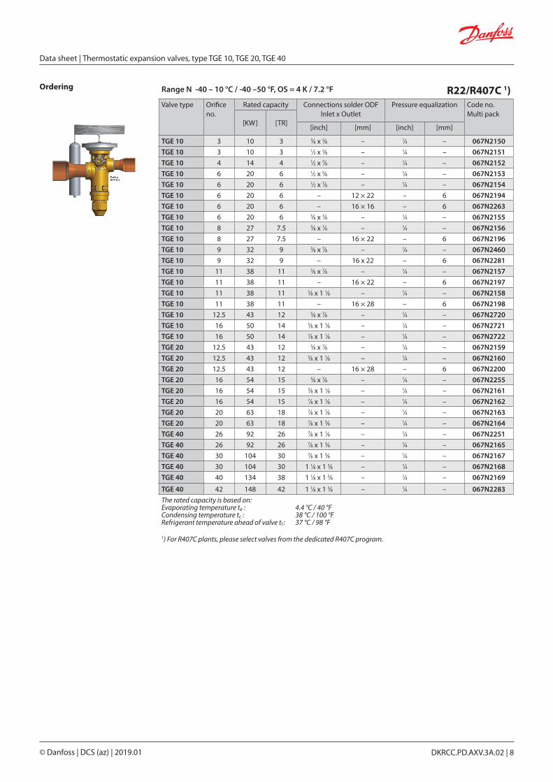
Range N -40 – 10 °C / -40 –50 °F, OS = 4 K / 7.2 °F R22/R407C 1)Valve type Orifice
no.Rated capacity Connections solder ODF
Inlet x Outlet Pressure equalization Code no.
Multi pack[KW] [TR]
[inch] [mm] [inch] [mm]
TGE 10 3 10 3 3⁄8 x 5⁄8 – 1⁄4 – 067N2150TGE 10 3 10 3 1⁄2 x 5⁄8 – 1⁄4 – 067N2151TGE 10 4 14 4 1⁄2 x 7⁄8 – 1⁄4 – 067N2152TGE 10 6 20 6 1⁄2 x 5⁄8 – 1⁄4 – 067N2153TGE 10 6 20 6 1⁄2 x 7⁄8 – 1⁄4 – 067N2154TGE 10 6 20 6 – 12 × 22 – 6 067N2194TGE 10 6 20 6 – 16 × 16 – 6 067N2263TGE 10 6 20 6 5⁄8 x 7⁄8 – 1⁄4 – 067N2155TGE 10 8 27 7.5 5⁄8 x 7⁄8 – 1⁄4 – 067N2156TGE 10 8 27 7.5 – 16 × 22 – 6 067N2196TGE 10 9 32 9 5⁄8 x 7⁄8 – 1⁄4 – 067N2460TGE 10 9 32 9 – 16 x 22 – 6 067N2281TGE 10 11 38 11 5⁄8 x 7⁄8 – 1⁄4 – 067N2157TGE 10 11 38 11 – 16 × 22 – 6 067N2197TGE 10 11 38 11 5⁄8 x 1 1⁄8 – 1⁄4 – 067N2158TGE 10 11 38 11 – 16 × 28 – 6 067N2198TGE 10 12.5 43 12 5⁄8 x 7⁄8 – 1⁄4 – 067N2720TGE 10 16 50 14 5⁄8 x 1 1⁄8 – 1⁄4 – 067N2721TGE 10 16 50 14 7⁄8 x 1 1⁄8 – 1⁄4 – 067N2722TGE 20 12.5 43 12 5⁄8 x 7⁄8 – 1⁄4 – 067N2159TGE 20 12.5 43 12 5⁄8 x 1 1⁄8 – 1⁄4 – 067N2160TGE 20 12.5 43 12 – 16 × 28 – 6 067N2200TGE 20 16 54 15 5⁄8 x 7⁄8 – 1⁄4 – 067N2255TGE 20 16 54 15 5⁄8 x 1 1⁄8 – 1⁄4 – 067N2161TGE 20 16 54 15 7⁄8 x 1 1⁄8 – 1⁄4 – 067N2162TGE 20 20 63 18 7⁄8 x 1 1⁄8 – 1⁄4 – 067N2163TGE 20 20 63 18 7⁄8 x 1 3⁄8 – 1⁄4 – 067N2164TGE 40 26 92 26 7⁄8 x 1 1⁄8 – 1⁄4 – 067N2251TGE 40 26 92 26 7⁄8 x 1 3⁄8 – 1⁄4 – 067N2165TGE 40 30 104 30 7⁄8 x 1 3⁄8 – 1⁄4 – 067N2167TGE 40 30 104 30 1 1⁄8 x 1 3⁄8 – 1⁄4 – 067N2168TGE 40 40 134 38 1 1⁄8 x 1 3⁄8 – 1⁄4 – 067N2169
TGE 40 42 148 42 1 1⁄8 x 1 3⁄8 – 1⁄4 – 067N2283The rated capacity is based on: Evaporating temperature te : 4.4 °C / 40 °FCondensing temperature tc : 38 °C / 100 °FRefrigerant temperature ahead of valve tl : 37 °C / 98 °F
1) For R407C plants, please select valves from the dedicated R407C program.
Ordering
Data sheet | Thermostatic expansion valves, type TGE 10, TGE 20, TGE 40
© Danfoss | DCS (az) | 2019.01 DKRCC.PD.AXV.3A.02 | 8

Range MAH -30 – 15 °C / -22 – 60 °F with anti hunting charge,OS = 4 K / 7.2 °F
R22/R407C 1)
Valve type Orifice no.
Rated capacity Connections solder ODF Code no. Multi pack
[KW] [TR]Inlet x Outlet
[inch]Pressure
equalization[inch]
TGE 10 6 20 6 1⁄2 x 7⁄8 1⁄4 067N9404TGE 10 8 27 7.5 5⁄8 x 7⁄8 1⁄4 067N9406TGE 10 11 38 11 5⁄8 x 7⁄8 1⁄4 067N9407TGE 20 12.5 43 12 5⁄8 x 7⁄8 1⁄4 067N9409TGE 20 16 54 15 7⁄8 x 1 1⁄8 1⁄4 067N9412TGE 20 20 63 18 7⁄8 x 1 3⁄8 1⁄4 067N9413TGE 40 26 92 26 7⁄8 x 1 3⁄8 1⁄4 067N9415TGE 40 30 104 30 1 1⁄8 x 1 3⁄8 1⁄4 067N9418TGE 40 40 134 38 1 1⁄8 x 1 3⁄8 1⁄4 067N9419The rated capacity is based on: Evaporating temperature te : 4.4 °C / 40 °FCondensing temperature tc : 38 °C / 100 °FRefrigerant temperature ahead of valve tl : 37 °C / 98 °F
1) For R407C plants, please select valves from the dedicated R407C program.
Range K –25 – 10 °C / –15 – 50 °F with MOP 15 °C / 60 °F, OS = 4 K / 7.2 °F
R22/R407C 1)
Valve type Orifice no.
Rated capacity Connections solder ODF Code no. Multi pack
[KW] [TR]Inlet x Outlet
[inch]Pressure
equalization[inch]
TGE 10 3 10 3 3⁄8 x 5⁄8 1⁄4 067N2000TGE 10 3 10 3 1⁄2 x 5⁄8 1⁄4 067N2001TGE 10 4 14 4 1⁄2 x 7⁄8 1⁄4 067N2002TGE 10 6 20 6 1⁄2 x 5⁄8 1⁄4 067N2003TGE 10 6 20 6 5⁄8 x 7⁄8 1⁄4 067N2005TGE 10 8 27 7.5 5⁄8 x 7⁄8 1⁄4 067N2006TGE 10 9 32 9 5⁄8 x 7⁄8 1⁄4 067N2415TGE 10 11 38 11 5⁄8 x 7⁄8 1⁄4 067N2007TGE 10 11 38 11 5⁄8 x 1 1⁄8 1⁄4 067N2008TGE 10 12.5 43 12 5⁄8 x 7⁄8 1⁄4 067N2700TGE 10 16 50 14 7⁄8 x 1 1⁄8 1⁄4 067N2701TGE 20 12.5 43 12 5⁄8 x 7⁄8 1⁄4 067N2009TGE 20 12.5 43 12 5⁄8 x 1 1⁄8 1⁄4 067N2010TGE 20 16 54 15 5⁄8 x 1 1⁄8 1⁄4 067N2011TGE 20 16 54 15 7⁄8 x 1 1⁄8 1⁄4 067N2012TGE 20 20 63 18 7⁄8 x 1 1⁄8 1⁄4 067N2013TGE 20 20 63 18 7⁄8 x 1 3⁄8 1⁄4 067N2014TGE 40 26 92 26 7⁄8 x 1 3⁄8 1⁄4 067N2015TGE 40 26 92 26 1 1⁄8 x 1 3⁄8 1⁄4 067N2016TGE 40 30 104 30 7⁄8 x 1 3⁄8 1⁄4 067N2017TGE 40 30 104 30 1 1⁄8 x 1 3⁄8 1⁄4 067N2018TGE 40 40 134 38 1 1⁄8 x 1 3⁄8 1⁄4 067N2019The rated capacity is based on: Evaporating temperature te : 4.4 °C / 40 °FCondensing temperature tc : 38 °C / 100 °FRefrigerant temperature ahead of valve tl : 37 °C / 98 °F
1) For R407C plants, please select valves from the dedicated R407C program.
Ordering
Data sheet | Thermostatic expansion valves, type TGE 10, TGE 20, TGE 40
© Danfoss | DCS (az) | 2019.01 DKRCC.PD.AXV.3A.02 | 9

Range N -40 – 10 °C / -40 –50 °F, OS = 4 K / 7.2 °F R134aValve type Orifice
no.Rated capacity Connections solder ODF Code no.
Multi pack[KW] [TR]
Inlet x Outlet Pressure equalization[inch] [mm] [inch] [mm]
TGE 10 3 6 1.5 3⁄8 x 5⁄8 – 1⁄4 – 067N5150TGE 10 3 6 1.5 – 12 × 16 – 6 067N5191TGE 10 4 8 2.5 1⁄2 x 7⁄8 – 1⁄4 – 067N5152TGE 10 4 8 2.5 – 12 × 22 – 6 067N5192TGE 10 6 12 3.5 1⁄2 x 5⁄8 – 1⁄4 – 067N5153TGE 10 6 12 3.5 1⁄2 x 7⁄8 – 1⁄4 – 067N5154TGE 10 6 12 3.5 – 16 × 22 – 6 067N5195TGE 10 8 17 4.5 5⁄8 x 7⁄8 – 1⁄4 – 067N5156TGE 10 8 17 4.5 – 16 × 22 – 6 067N5196TGE 10 9 20 5.5 5⁄8 x 7⁄8 – 1⁄4 – 067N5260TGE 10 11 24 7 5⁄8 x 7⁄8 – 1⁄4 – 067N5157TGE 10 12.5 29 8 5⁄8 x 7⁄8 – 1⁄4 – 067N5720TGE 10 16 35 9.5 7⁄8 x 1 1⁄8 – 1⁄4 – 067N5721TGE 20 12.5 29 8 5⁄8 x 7⁄8 – 1⁄4 – 067N5159TGE 20 16 37 10 5⁄8 x 1 1⁄8 – 1⁄4 – 067N5161TGE 20 16 37 10 7⁄8 x 1 1⁄8 – 1⁄4 – 067N5162TGE 20 20 44 12 7⁄8 x 1 1⁄8 – 1⁄4 – 067N5163TGE 40 26 61 17 7⁄8 x 1 3⁄8 – 1⁄4 – 067N5165TGE 40 26 61 17 1 1⁄8 x 1 3⁄8 – 1⁄4 – 067N5166TGE 40 30 70 20 7⁄8 x 1 3⁄8 – 1⁄4 – 067N5167TGE 40 30 70 20 1 1⁄8 x 1 3⁄8 – 1⁄4 – 067N5168TGE 40 40 87 25 1 1⁄8 x 1 3⁄8 – 1⁄4 – 067N5169The rated capacity is based on: Evaporating temperature te : 4.4 °C / 40 °FCondensing temperature tc : 38 °C / 100 °FRefrigerant temperature ahead of valve tl : 37 °C / 98 °F
Range N -40 – 10 °C / -40 –50 °F, OS = 4 K / 7.2 °F R134aValve type Orifice
no.Rated capacity Connections flare / MIO Code no.
Multi pack
[KW] [TR]Inlet x Outlet
[inch]Pressure equalization
[inch] Flare MIO Flare MIO
TGE 10 3 6 1.5 – 1⁄2 x 5⁄8 – 1⁄4 067N7150TGE 10 4 8 2.5 – 3⁄8 x 1⁄2 1⁄4 – 067N7153TGE 10 4 8 2.5 3⁄8 x 1⁄2 – 1⁄4 – 067N7154TGE 10 6 12 3.5 – 1⁄2 x 5⁄8 – 1⁄4 067N7171TGE 10 6 12 3.5 1⁄2 x 5⁄8 – 1⁄4 – 067N7157TGE 10 6 12 3.5 – 3⁄8 x 1⁄2 1⁄4 – 067N7158TGE 10 6 12 3.5 3⁄8 x 1⁄2 – 1⁄4 – 067N7160TGE 10 6 12 3.5 – 3⁄8 x 1⁄2 – 1⁄4 067N7177TGE 10 8 17 4.5 – 3⁄8 × 1⁄2 – 1⁄4 067N7176TGE 10 8 17 4.5 – 1⁄2 × 5⁄8 – 1⁄4 067N7161TGE 10 8 17 4.5 1⁄2 × 5⁄8 – 1⁄4 – 067N7163TGE 10 8 17 4.5 – 3⁄8 x 1⁄2 1⁄4 – 067N7164TGE 10 8 17 4.5 – 5⁄8 x 3⁄4 – 1⁄4 067N7165TGE 10 9 20 5.5 – 5⁄8 x 3⁄4 – 1⁄4 067N7181TGE 10 11 24 7 – 5⁄8 x 3⁄4 – 1⁄4 067N7166TGE 10 12.5 29 8 – 5⁄8 x 3⁄4 – 1⁄4 067N7200TGE 10 16 35 9.5 – 5⁄8 x 3⁄4 – 1⁄4 067N7201TGE 10 16 35 9.5 5⁄8 x 3⁄4 – 1⁄4 – 067N7203TGE 20 12.5 29 8 – 5⁄8 x 3⁄4 – 1⁄4 067N7167TGE 20 16 37 10 – 5⁄8 x 3⁄4 – 1⁄4 067N7169TGE 20 16 37 10 5⁄8 x 3⁄4 – 1⁄4 – 067N7168TGE 20 20 44 12 – 5⁄8 x 3⁄4 – 1⁄4 067N7174The rated capacity is based on: Evaporating temperature te : 4.4 °C / 40 °FCondensing temperature tc : 38 °C / 100 °FRefrigerant temperature ahead of valve tl : 37 °C / 98 °F
Ordering
Data sheet | Thermostatic expansion valves, type TGE 10, TGE 20, TGE 40
© Danfoss | DCS (az) | 2019.01 DKRCC.PD.AXV.3A.02 | 10

Range K –25 – 10 °C / –15 – 50 °F with MOP 15 °C / 60°F, OS = 4 K / 7.2 °F R134aValve type Orifice
no.Rated capacity Connections flare / MIO Code no.
Multi pack
[KW] [TR]Inlet x Outlet
[inch]Pressure equalization
[inch]Flare MIO Flare MIO
TGE 10 4 8 2.5 – 1⁄2 × 5⁄8 – 1⁄4 067N7002TGE 10 6 12 3.5 3⁄8 x 1⁄2 – 1⁄4 – 067N7003TGE 10 6 12 3.5 1⁄2 x 5⁄8 – 1⁄4 – 067N7004TGE 10 8 17 4.5 – 1⁄2 × 5⁄8 – 1⁄4 067N7010TGE 10 8 17 4.5 1⁄2 x 5⁄8 – 1⁄4 – 067N7008TGE 10 8 17 4.5 – 5⁄8 x 3⁄4 – 1⁄4 067N7012TGE 10 8 17 4.5 5⁄8 x 3⁄4 – 1⁄4 – 067N7013TGE 10 9 20 5.5 – 5⁄8 x 3⁄4 – 1⁄4 067N7046TGE 10 11 24 7 – 5⁄8 x 3⁄4 – 1⁄4 067N7015TGE 10 11 24 7 5⁄8 x 3⁄4 – 1⁄4 – 067N7016TGE 10 12.5 29 8 – 5⁄8 x 3⁄4 – 1⁄4 067N7210TGE 10 12.5 29 8 5⁄8 x 3⁄4 – 1⁄4 – 067N7212TGE 10 16 35 9.5 – 5⁄8 x 3⁄4 – 1⁄4 067N7211TGE 20 12.5 29 8 – 5⁄8 x 3⁄4 – 1⁄4 067N7017TGE 20 12.5 29 8 5⁄8 x 3⁄4 – 1⁄4 – 067N7018TGE 20 16 37 10 – 5⁄8 x 3⁄4 – 1⁄4 067N7019TGE 20 16 37 10 5⁄8 x 3⁄4 – 1⁄4 – 067N7020TGE 20 20 44 12 5⁄8 x 3⁄4 – 1⁄4 – 067N7021The rated capacity is based on: Evaporating temperature te : 4.4 °C / 40 °FCondensing temperature tc : 38 °C / 100 °FRefrigerant temperature ahead of valve tl : 37 °C / 98 °F
Range K -25 – 10 °C /-15 – 50 °F with MOP 15 °C / 60 °F, OS = 4 K / 7.2 °F R134aValve type Orifice
no.Rated capacity Connections solder ODF Code no.
Multi pack[KW] [TR]
Inlet x Outlet Pressure equalization [inch] [mm] [inch] [mm]
TGE 10 3 6 1.5 3⁄8 x 5⁄8 – 1⁄4 – 067N5000TGE 10 4 8 2.5 1⁄2 x 7⁄8 – 1⁄4 – 067N5002TGE 10 6 12 3.5 1⁄2 x 5⁄8 – 1⁄4 – 067N5003TGE 10 6 12 3.5 – 12 × 16 – 6 067N5043TGE 10 6 12 3.5 5⁄8 x 7⁄8 – 1⁄4 – 067N5005TGE 10 8 17 4.5 5⁄8 x 7⁄8 – 1⁄4 – 067N5006TGE 10 11 24 7 5⁄8 x 7⁄8 – 1⁄4 – 067N5007TGE 10 11 24 7 – 16 × 22 – 6 067N5047TGE 10 11 24 7 5⁄8 x 1 1⁄8 – 1⁄4 – 067N5008TGE 10 12.5 29 8 5⁄8 x 7⁄8 – 1⁄4 – 067N5700TGE 20 12.5 29 8 5⁄8 x 7⁄8 – 1⁄4 – 067N5009TGE 20 16 37 10 5⁄8 x 1 1⁄8 – 1⁄4 – 067N5011TGE 20 20 44 12 7⁄8 x 1 1⁄8 – 1⁄4 – 067N5013TGE 40 26 61 17 7⁄8 x 1 3⁄8 – 1⁄4 – 067N5015TGE 40 30 70 20 1 1⁄8 x 1 3⁄8 – 1⁄4 – 067N5018TGE 40 40 87 25 1 1⁄8 x 1 3⁄8 – 1⁄4 – 067N5019The rated capacity is based on: Evaporating temperature te : 4.4 °C / 40 °FCondensing temperature tc : 38 °C / 100 °FRefrigerant temperature ahead of valve tl : 37 °C / 98 °F
Ordering
Data sheet | Thermostatic expansion valves, type TGE 10, TGE 20, TGE 40
© Danfoss | DCS (az) | 2019.01 DKRCC.PD.AXV.3A.02 | 11

Only solder versions, connection size 28 mm / 1 1⁄8 in. or below are approved for flammable refrigerants.
Range –30 – 10 °C/ –22 – 50 °F,OS = 4 K/7.2 °F R1234zeValve type Orifice
no.Rated capacity Connections solder ODF Code no.
Multi pack[KW] [TR]
Inlet x Outlet Pressure equalization [inch] [inch]
TGE 10 8 14 4 5⁄8 x 7⁄8 1⁄4 067N8001TGE 10 11 20 5.5 5⁄8 x 7⁄8 1⁄4 067N8002TGE 10 12.5 22 6 5⁄8 x 7⁄8 1⁄4 067N8003TGE 20 20 31 8.5 7⁄8 x 1 1⁄8 1⁄4 067N8004TGE 40 26 49 14 7⁄8 x 1 1⁄8 1⁄4 067N8005
The rated capacity is based on: Evaporating temperature te : 4.4 °C / 40 °FCondensing temperature tc : 38 °C / 100 °FRefrigerant temperature ahead of valve tl : 37 °C / 98 °F
Ordering
Range N -40 – 10 °C / -40 –50 °F, OS = 4 K / 7.2 °F R407F/R407A1)Valve type Orifice no. Rated capacity
R407FRated capacity
R407AConnections solder ODF Code no.
Multi pack
[KW] [TR] [KW] [TR]Inlet x Outlet Pressure
equalization
[inch] [inch]TGE 10 4 14 4 12 3.5 1⁄2 x 7⁄8 1⁄4 067N4700
TGE 10 6 20 6 17 5 5⁄8 x 7⁄8 1⁄4 067N4701TGE 10 8 27 7.5 23 6.5 5⁄8 x 7⁄8 1⁄4 067N4702TGE 10 9 32 9 28 8 5⁄8 x 7⁄8 1⁄4 067N4703TGE 10 11 40 11 34 10 5⁄8 x 1 1⁄8 1⁄4 067N4704
The rated capacity is based on: Evaporating temperature te : 4.4 °C / 40 °FCondensing temperature tc : 38 °C / 100 °FRefrigerant temperature ahead of valve tl : 37 °C / 98 °F
1) On systems charged with R407F, SS = 4.0 °C / 7.2 °F, on systems charged with R407A, SS = 2.7 °C / 4.9 °F.
Range N -40 – 10 °C / -40 –50 °F, OS = 4 K / 7.2 °F R404A/R507Valve type Orifice no. Rated capacity Connections solder ODF Code no.
Multi pack[KW] [TR]
Inlet x Outlet[inch]
Pressure equalization [inch]
TGE 10 3 7 2 3⁄8 x 5⁄8 1⁄4 067N6170TGE 10 4 9 2.5 1⁄2 x 7⁄8 1⁄4 067N6172TGE 10 6 14 4 1⁄2 x 5⁄8 1⁄4 067N6173TGE 10 6 14 4 1⁄2 x 7⁄8 1⁄4 067N6151TGE 10 8 18 5 1⁄2 x 5⁄8 1⁄4 067N6175TGE 10 8 18 5 5⁄8 x 7⁄8 1⁄4 067N6150TGE 10 9 21 6 5⁄8 x 7⁄8 1⁄4 067N6167TGE 10 11 26 7.5 5⁄8 x 7⁄8 1⁄4 067N6154TGE 10 12.5 31 9 5⁄8 x 7⁄8 1⁄4 067N6300TGE 10 16 35 10 5⁄8 x 1 1⁄8 1⁄4 067N6301TGE 20 12.5 31 9 5⁄8 x 7⁄8 1⁄4 067N6158TGE 20 16 39 11 5⁄8 x 1 1⁄8 1⁄4 067N6155TGE 20 16 39 11 1 1⁄8 x 1 3⁄8 1⁄4 067N6188TGE 20 16 39 11 7⁄8 x 1 1⁄8 1⁄4 067N6181TGE 20 20 45 13 7⁄8 x 1 1⁄8 1⁄4 067N6162TGE 40 26 64 18 7⁄8 x 1 3⁄8 1⁄4 067N6161TGE 40 30 72 21 1 1⁄8 x 1 3⁄8 1⁄4 067N6186TGE 40 40 92 26 1 1⁄8 x 1 3⁄8 1⁄4 067N6187
The rated capacity is based on: Evaporating temperature te : 4.4 °C / 40 °FCondensing temperature tc : 38 °C / 100 °FRefrigerant temperature ahead of valve tl : 37 °C / 98 °F
Data sheet | Thermostatic expansion valves, type TGE 10, TGE 20, TGE 40
© Danfoss | DCS (az) | 2019.01 DKRCC.PD.AXV.3A.02 | 12

Ordering
Range N -40 – 10 °C / -40 –50 °F, OS = 4 K / 7.2 °F R407CValve type Orifice
no.Rated capacity Connections MIO Code no.
Multi pack[KW] [TR] Inlet x Outlet inch Pressure equalization inchTGE 10 4 13 3.5 1⁄2 x 5⁄8 MIO 1⁄4 MIO 067N7400TGE 10 6 19 5 1⁄2 x 5⁄8 MIO 1⁄4 MIO 067N7401TGE 10 8 25 7 5⁄8 x 3⁄4 MIO 1⁄4 MIO 067N7402TGE 10 11 36 10 5⁄8 x 3⁄4 MIO 1⁄4 MIO 067N7403The rated capacity is based on: Evaporating temperature te : 4.4 °C / 40 °FCondensing temperature tc : 38 °C / 100 °FRefrigerant temperature ahead of valve tl : 37 °C / 98 °F
Range N -40 – 10 °C / -40 –50 °F, OS = 4 K / 7.2 °F R407CValve type Orifice
no.Rated capacity Connections solder ODF Code no.
Multi pack[KW] [TR]
Inlet x Outlet Pressure equalization [inch] [mm] [inch] [mm]
TGE 10 3 9 2.5 1⁄2 x 5⁄8 – 1⁄4 – 067N4151TGE 10 3 9 2.5 – 12 × 16 – 6 067N4191TGE 10 4 13 3.5 1⁄2 x 7⁄8 – 1⁄4 – 067N4152TGE 10 4 13 3.5 – 12 × 22 – 6 067N4192TGE 10 6 19 5 1⁄2 x 5⁄8 – 1⁄4 – 067N4153TGE 10 6 19 5 – 12 × 16 – 6 067N4193TGE 10 8 25 7 1⁄2 x 5⁄8 – 1⁄4 – 067N4236TGE 10 8 25 7 5⁄8 x 7⁄8 – 1⁄4 – 067N4156TGE 10 8 25 7 – 16 × 22 – 6 067N4196TGE 10 11 36 10 5⁄8 x 7⁄8 – 1⁄4 – 067N4157TGE 10 11 36 10 – 16 × 22 – 6 067N4197TGE 10 12.5 39 11 5⁄8 x 7⁄8 – 1⁄4 – 067N4410TGE 10 16 49 14 7⁄8 x 1 1⁄8 – 1⁄4 – 067N4411TGE 20 12.5 42 12 5⁄8 x 7⁄8 – 1⁄4 – 067N4159TGE 20 16 53 15 5⁄8 x 1 1⁄8 – 1⁄4 – 067N4161TGE 20 16 53 15 7⁄8 x 1 1⁄8 – 1⁄4 – 067N4162TGE 20 20 62 18 7⁄8 x 1 1⁄8 – 1⁄4 – 067N4163TGE 40 26 84 24 7⁄8 x 1 3⁄8 – 1⁄4 – 067N4165TGE 40 30 95 27 7⁄8 x 1 3⁄8 – 1⁄4 – 067N4167TGE 40 40 121 34 1 1⁄8 x 1 3⁄8 – 1⁄4 – 067N4169
The rated capacity is based on: Evaporating temperature te : 4.4 °C / 40 °FCondensing temperature tc : 38 °C / 100 °FRefrigerant temperature ahead of valve tl : 37 °C / 98 °F
Data sheet | Thermostatic expansion valves, type TGE 10, TGE 20, TGE 40
© Danfoss | DCS (az) | 2019.01 DKRCC.PD.AXV.3A.02 | 13

Ordering Range K –25 – 10 °C / –15 – 50 °F with MOP 15 °C / 60 °F, OS = 4 K / 7.2 °F R407CValve type Orifice
no.Rated capacity Connections solder ODF Code no.
Multi pack[KW] [TR]
Inlet x Outlet Pressure equalization [inch] [mm] [inch] [mm]
TGE 10 3 9 2.5 3⁄8 x 5⁄8 – 1⁄4 – 067N4000TGE 10 3 9 2.5 – 12 × 16 – 6 067N4041TGE 10 4 13 3.5 1⁄2 x 7⁄8 – 1⁄4 – 067N4002TGE 10 6 19 5 1⁄2 x 5⁄8 – 1⁄4 – 067N4003TGE 10 6 19 5 1⁄2 x 7⁄8 – 1⁄4 – 067N4004TGE 10 8 25 7 5⁄8 x 7⁄8 – 1⁄4 – 067N4006TGE 10 8 25 7 – 16 × 22 – 6 067N4046TGE 10 11 36 10 5⁄8 x 7⁄8 – 1⁄4 – 067N4007TGE 10 11 36 10 – 16 × 22 – 6 067N4047TGE 10 12.5 39 11 5⁄8 x 1 1⁄8 – 1⁄4 – 067N4400TGE 10 16 49 14 5⁄8 x 1 1⁄8 – 1⁄4 – 067N4401TGE 20 12.5 42 12 5⁄8 x 7⁄8 – 1⁄4 – 067N4009TGE 20 12.5 42 12 5⁄8 x 1 1⁄8 – 1⁄4 – 067N4010TGE 20 16 53 15 5⁄8 x 1 1⁄8 – 1⁄4 – 067N4011TGE 20 20 62 18 7⁄8 x 1 1⁄8 – 1⁄4 – 067N4013TGE 40 26 84 24 7⁄8 x 1 3⁄8 – 1⁄4 – 067N4015TGE 40 30 95 27 7⁄8 x 1 3⁄8 – 1⁄4 – 067N4017TGE 40 40 121 34 1 1⁄8 x 1 3⁄8 – 1⁄4 – 067N4019The rated capacity is based on: Evaporating temperature te : 4.4 °C / 40 °FCondensing temperature tc : 38 °C / 100 °FRefrigerant temperature ahead of valve tl : 37 °C / 98 °F
Only solder versions, connection size 28mm / 1 1⁄8 in. or below are approved for flammable refrigerants.
Range N -40 – 10 °C / -40 – 50 °F, OS = 4 K / 7.2 °F R2901)Valve type Orifice no. Rated capacity Connections solder ODF Code no.
Multi pack[KW] [TR]
Inlet x Outlet Pressure equalization [inch] [inch]
TGE 10 6 19 5 5⁄8 x 7⁄8 1⁄4 067N9100TGE 10 11 36 10 5⁄8 × 7⁄8 1⁄4 067N9103TGE 20 12.5 44 12 5⁄8 × 7⁄8 1⁄4 067N9104TGE 20 16 54 15 7⁄8 × 7⁄8 1⁄4 067N9105TGE 20 20 63 18 7⁄8 × 7⁄8 1⁄4 067N9106
Range K –25 – 10 °C / –15 – 50 °F without MOP, OS = 4 K / 7.2 °F R2901)Valve type Orifice
no.Rated capacity Connections solder ODF Code no.
Multi pack
[KW] [TR]Inlet x Outlet Pressure
equalization [inch] [inch]
TGE 40 26 92 26 7⁄8 × 7⁄8 1⁄4 067N9107TGE 40 40 133 38 7⁄8 × 7⁄8 1⁄4 067N9109
The rated capacity is based on: Evaporating temperature te : 4.4 °C / 40 °FCondensing temperature tc : 38 °C / 100 °FRefrigerant temperature ahead of valve tl : 37 °C / 98 °F1) SS = 5K / 9°F (except 067N9100, 067N9103)
Bulb straps (delivered separately) in Industrial pack
Code no. Max. tube diameter Quantity / pack
067N0551 7⁄8 40
067N0557 2 1⁄8 40
067N0559 3 1⁄8 40
Ordering(Spare parts)
Data sheet | Thermostatic expansion valves, type TGE 10, TGE 20, TGE 40
© Danfoss | DCS (az) | 2019.01 DKRCC.PD.AXV.3A.02 | 14
4
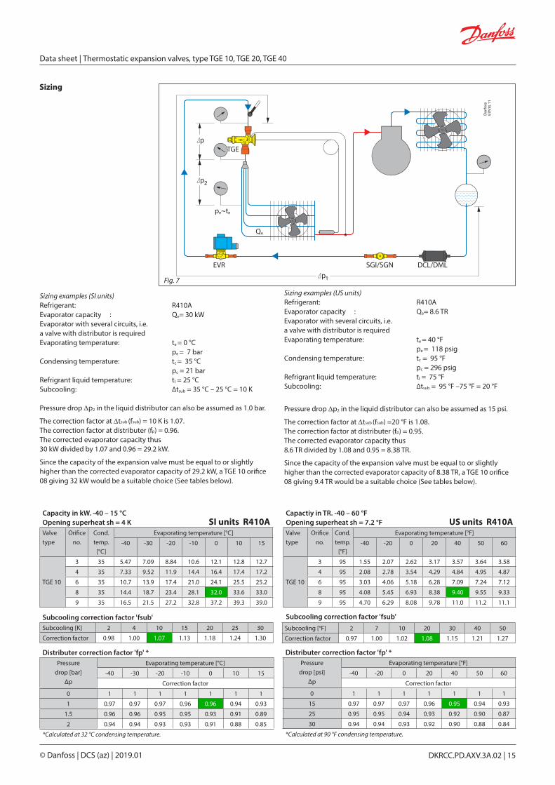
Fig. 7
Sizing
Sizing examples (SI units)Refrigerant: R410AEvaporator capacity : Qe= 30 kWEvaporator with several circuits, i.e. a valve with distributor is requiredEvaporating temperature: te = 0 °C pe = 7 barCondensing temperature: tc = 35 °C pc = 21 barRefrigrant liquid temperature: tl = 25 °CSubcooling: ∆tsub = 35 °C – 25 °C = 10 K
Pressure drop ∆p2 in the liquid distributor can also be assumed as 1.0 bar.
The correction factor at ∆tsub (fsub) = 10 K is 1.07.The correction factor at distributer (fp) = 0.96.The corrected evaporator capacity thus 30 kW divided by 1.07 and 0.96 = 29.2 kW.
Since the capacity of the expansion valve must be equal to or slightly higher than the corrected evaporator capacity of 29.2 kW, a TGE 10 orifice 08 giving 32 kW would be a suitable choice (See tables below).
EVR SGI/SGN DCL/DML
Qe
pe~te
TGE
Subcooling correction factor 'fsub'Subcooling [K] 2 4 10 15 20 25 30
Correction factor 0.98 1.00 1.07 1.13 1.18 1.24 1.30
Distributer correction factor 'fp' *Pressure
drop [bar]Δp
Evaporating temperature [°C]
-40 -30 -20 -10 0 10 15
Correction factor
0 1 1 1 1 1 1 1
1 0.97 0.97 0.97 0.96 0.96 0.94 0.93
1.5 0.96 0.96 0.95 0.95 0.93 0.91 0.89
2 0.94 0.94 0.93 0.93 0.91 0.88 0.85
*Calculated at 32 °C condensing temperature.
Subcooling correction factor 'fsub'Subcooling [°F] 2 7 10 20 30 40 50
Correction factor 0.97 1.00 1.02 1.08 1.15 1.21 1.27
Distributer correction factor 'fp' *Pressure
drop [psi]Δp
Evaporating temperature [°F]
-40 -20 0 20 40 50 60
Correction factor
0 1 1 1 1 1 1 1
15 0.97 0.97 0.97 0.96 0.95 0.94 0.93
25 0.95 0.95 0.94 0.93 0.92 0.90 0.87
30 0.94 0.94 0.93 0.92 0.90 0.88 0.84
*Calculated at 90 °F condensing temperature.
Capacity in kW. -40 – 15 °COpening superheat sh = 4 K SI units R410AValve type
Orifice no.
Cond. temp.
[°C]
Evaporating temperature [°C]
-40 -30 -20 -10 0 10 15
TGE 10
3 35 5.47 7.09 8.84 10.6 12.1 12.8 12.7
4 35 7.33 9.52 11.9 14.4 16.4 17.4 17.2
6 35 10.7 13.9 17.4 21.0 24.1 25.5 25.2
8 35 14.4 18.7 23.4 28.1 32.0 33.6 33.0
9 35 16.5 21.5 27.2 32.8 37.2 39.3 39.0
Capactiy in TR. -40 – 60 °FOpening superheat sh = 7.2 °F US units R410AValve type
Orifice no.
Cond. temp.
[°F]
Evaporating temperature [°F]
-40 -20 0 20 40 50 60
TGE 10
3 95 1.55 2.07 2.62 3.17 3.57 3.64 3.58
4 95 2.08 2.78 3.54 4.29 4.84 4.95 4.87
6 95 3.03 4.06 5.18 6.28 7.09 7.24 7.12
8 95 4.08 5.45 6.93 8.38 9.40 9.55 9.33
9 95 4.70 6.29 8.08 9.78 11.0 11.2 11.1
Sizing examples (US units)Refrigerant: R410AEvaporator capacity : Qe= 8.6 TREvaporator with several circuits, i.e. a valve with distributor is requiredEvaporating temperature: te = 40 °F pe = 118 psigCondensing temperature: tc = 95 °F pc = 296 psigRefrigrant liquid temperature: tl = 75 °FSubcooling: ∆tsub = 95 °F –75 °F = 20 °F
Pressure drop ∆p2 in the liquid distributor can also be assumed as 15 psi.
The correction factor at ∆tsub (fsub) =20 °F is 1.08.The correction factor at distributer (fp) = 0.95.The corrected evaporator capacity thus 8.6 TR divided by 1.08 and 0.95 = 8.38 TR.
Since the capacity of the expansion valve must be equal to or slightly higher than the corrected evaporator capacity of 8.38 TR, a TGE 10 orifice 08 giving 9.4 TR would be a suitable choice (See tables below).
Data sheet | Thermostatic expansion valves, type TGE 10, TGE 20, TGE 40
© Danfoss | DCS (az) | 2019.01 DKRCC.PD.AXV.3A.02 | 15

Capacity in kW. -40 – 15 °COpening superheat sh = 4 K SI units R410AValve type
Orifice no.
Cond. temp.
[°C]
Evaporating temperature [°C]
-40 -30 -20 -10 0 10 15
TGE 10
3 25 5.63 7.19 8.80 10.2 11.1 10.7 9.68
4 25 7.60 9.73 12.0 14.0 15.2 14.6 13.2
6 25 11.2 14.4 17.7 20.6 22.4 21.6 19.5
8 25 15.2 19.5 23.8 27.7 29.9 28.6 25.7
9 25 17.4 22.3 27.6 32.4 35.3 34.1 30.7
11 25 22.6 29.1 35.4 40.3 42.1 38.4 33.8
12.5 25 23.2 30.0 37.2 43.8 47.7 46.3 41.7
16 25 27.3 35.0 43.3 50.7 55.3 53.4 47.8
TGE 20
12.5 25 22.7 30.1 38.3 46.4 52.1 51.6 47.3
16 25 28.3 37.7 48.1 58.5 66.2 66.0 60.7
20 25 34.8 45.9 57.8 69.3 77.0 75.1 67.9
21 25 45.7 59.0 72.0 81.9 85.2 78.2 68.4
TGE 40
26 25 45.1 59.7 76.7 94.5 108.7 110 101
30 25 51.3 68.0 87.3 108 123 124 114
40 25 61.9 82.1 106 132 152 154 140
42 25 90.8 115 140 161 170 158 139
Capactiy in TR. -40 – 60 °FOpening superheat sh = 7.2 °F US units R410AValve type
Orifice no.
Cond. temp.
[°F]
Evaporating temperature [°F]
-40 -20 0 20 40 50 60
TGE 10
3 75 1.60 2.09 2.59 2.99 3.10 2.95 2.57
4 75 2.16 2.83 3.52 4.07 4.24 4.03 3.52
6 75 3.19 4.19 5.20 6.03 6.26 5.95 5.17
8 75 4.33 5.67 7.02 8.09 8.33 7.88 6.81
9 75 4.96 6.51 8.16 9.50 9.89 9.41 8.10
11 75 6.44 8.48 10.4 11.6 11.5 10.6 8.93
12.5 75 6.62 8.76 11.0 12.9 13.4 12.8 11.0
16 75 7.77 10.2 12.8 14.9 15.5 14.7 12.6
TGE 20
12.5 75 6.47 8.83 11.4 13.8 14.8 14.3 12.6
16 75 8.08 11.1 14.4 17.4 18.9 18.3 16.2
20 75 9.94 13.5 17.2 20.5 21.7 20.7 18.1
21 75 13.0 17.2 21.1 23.6 23.3 21.5 17.9
TGE 40
26 75 12.9 17.6 23.0 28.3 31.2 30.4 26.9
30 75 14.7 20.0 26.2 32.2 35.4 34.4 30.4
40 75 17.7 24.1 31.9 39.6 43.7 42.5 37.0
42 75 25.7 33.4 41.0 46.5 46.8 43.5 36.3
Subcooling correction factor 'fsub'Subcooling [K] 2 4 10 15 20 25 30
Correction factor 0.98 1.00 1.07 1.13 1.18 1.24 1.30
Distributer correction factor 'fp' *Pressure
drop [bar]Δp
Evaporating temperature [°C]
-40 -30 -20 -10 0 10 15
Correction factor
0 1 1 1 1 1 1 1
1 0.97 0.97 0.97 0.96 0.96 0.94 0.93
1.5 0.96 0.96 0.95 0.95 0.93 0.91 0.89
2 0.94 0.94 0.93 0.93 0.91 0.88 0.85
*Calculated at 32 °C condensing temperature.
Subcooling correction factor 'fsub'Subcooling [°F] 2 7 10 20 30 40 50
Correction factor 0.97 1.00 1.02 1.08 1.15 1.21 1.27
Distributer correction factor 'fp' *Pressure
drop [psi]Δp
Evaporating temperature [°F]
-40 -20 0 20 40 50 60
Correction factor
0 1 1 1 1 1 1 1
15 0.97 0.97 0.97 0.96 0.95 0.94 0.93
25 0.95 0.95 0.94 0.93 0.92 0.90 0.87
30 0.94 0.94 0.93 0.92 0.90 0.88 0.84
*Calculated at 90 °F condensing temperature.
Capacity in kW. -40 – 15 °COpening superheat sh = 4 K SI units R410AValve type
Orifice no.
Cond. temp.
[°C]
Evaporating temperature [°C]
-40 -30 -20 -10 0 10 15
TGE 10
3 35 5.47 7.09 8.84 10.6 12.1 12.8 12.7
4 35 7.33 9.52 11.9 14.4 16.4 17.4 17.2
6 35 10.7 13.9 17.4 21.0 24.1 25.5 25.2
8 35 14.4 18.7 23.4 28.1 32.0 33.6 33.0
9 35 16.5 21.5 27.2 32.8 37.2 39.3 39.0
11 35 21.4 28.2 35.3 41.8 46.1 46.4 44.4
12.5 35 21.9 28.7 36.3 43.9 50.0 53.1 52.8
16 35 25.7 33.5 42.3 51.0 58.2 62.0 61.7
TGE 20
12.5 35 21.3 28.5 36.8 45.9 54.3 59.4 59.5
16 35 26.4 35.3 45.8 57.4 68.4 75.4 75.7
20 35 32.4 43.1 55.2 68.3 80.4 87.2 86.6
21 35 44.8 58.7 73.0 85.2 92.6 92.9 89.9
TGE 40
26 35 41.5 55.4 72.1 91.3 111 124 126
30 35 47.0 62.8 81.8 104 125 140 142
40 35 57.4 77.2 102 130 157 175 177
42 35 90.3 116 143 169 186 189 184
Capactiy in TR. -40 – 60 °FOpening superheat sh = 7.2 °F US units R410AValve type
Orifice no.
Cond. temp.
[°F]
Evaporating temperature [°F]
-40 -20 0 20 40 50 60
TGE 10
3 95 1.55 2.07 2.62 3.17 3.57 3.64 3.58
4 95 2.08 2.78 3.54 4.29 4.84 4.95 4.87
6 95 3.03 4.06 5.18 6.28 7.09 7.24 7.12
8 95 4.08 5.45 6.93 8.38 9.40 9.55 9.33
9 95 4.70 6.29 8.08 9.78 11.0 11.2 11.1
11 95 6.07 8.23 10.5 12.4 13.3 13.2 12.5
12.5 95 6.20 8.37 10.8 13.1 14.7 15.1 15.0
16 95 7.29 9.79 12.6 15.2 17.2 17.6 17.5
TGE 20
12.5 95 6.06 8.34 11.0 13.9 16.3 16.9 16.9
16 95 7.48 10.3 13.7 17.4 20.5 21.4 21.5
20 95 9.19 12.6 16.5 20.6 24.0 24.8 24.5
21 95 12.7 17.1 21.6 25.1 26.6 26.4 25.4
TGE 40
26 95 11.8 16.2 21.6 27.8 33.4 35.2 35.7
30 95 13.3 18.4 24.5 31.5 37.9 39.9 40.3
40 95 16.3 22.6 30.7 39.7 47.3 49.6 50.1
42 95 25.7 33.7 42.4 49.8 53.8 53.8 51.8
Data sheet | Thermostatic expansion valves, type TGE 10, TGE 20, TGE 40
© Danfoss | DCS (az) | 2019.01 DKRCC.PD.AXV.3A.02 | 16

Capacity in kW. -40 – 15 °COpening superheat sh = 4 K SI units R410AValve type
Orifice no.
Cond. temp.
[°C]
Evaporating temperature [°C]
-40 -30 -20 -10 0 10 15
TGE 10
3 45 5.14 6.72 8.47 10.3 12.2 13.6 13.9
4 45 6.83 8.95 11.3 13.9 16.4 18.3 18.8
6 45 9.83 12.9 16.4 20.1 23.8 26.6 27.3
8 45 13.1 17.2 21.8 26.7 31.5 35.0 35.7
9 45 15.1 19.9 25.5 31.4 36.7 40.5 41.6
11 45 19.4 26.1 33.4 40.7 46.7 49.7 49.4
12.5 45 19.6 26.2 33.7 41.6 48.8 54.2 56.0
16 45 23.1 30.7 39.4 48.6 57.2 63.9 66.1
TGE 20
12.5 45 19.4 25.9 33.7 42.6 51.9 60.0 62.6
16 45 23.8 31.9 41.6 52.8 64.8 75.3 78.9
20 45 29.1 38.9 50.3 63.1 76.7 88.5 92.2
21 45 42.4 56.3 71.1 84.7 94.3 98.7 98.8
TGE 40
26 45 37.0 49.5 64.7 82.9 103 122 129
30 45 41.7 55.9 73.2 93.8 117 138 145
40 45 50.9 69.2 92.9 121 151 176 185
42 45 87.1 113 141 169 191 202 203
Capactiy in TR. -40 – 60 °FOpening superheat sh = 7.2 °F US units R410AValve type
Orifice no.
Cond. temp.
[°F]
Evaporating temperature [°F]
-40 -20 0 20 40 50 60
TGE 10
3 115 1.45 1.94 2.50 3.10 3.64 3.85 3.97
4 115 1.92 2.59 3.35 4.16 4.91 5.20 5.37
6 115 2.76 3.73 4.84 6.02 7.12 7.54 7.78
8 115 3.66 4.97 6.43 7.98 9.39 9.90 10.2
9 115 4.22 5.75 7.54 9.38 10.9 11.5 11.9
11 115 5.43 7.56 9.87 12.1 13.8 14.1 14.1
12.5 115 5.49 7.55 9.96 12.4 14.6 15.4 16.0
16 115 6.45 8.85 11.6 14.5 17.1 18.1 18.9
TGE 20
12.5 115 5.44 7.49 9.97 12.8 15.7 16.9 17.8
16 115 6.65 9.21 12.3 15.9 19.6 21.2 22.4
20 115 8.15 11.2 14.9 19.0 23.2 25.0 26.2
21 115 11.9 16.3 21.0 25.0 27.5 28.1 28.2
TGE 40
26 115 10.3 14.3 19.2 25.1 31.4 34.3 36.6
30 115 11.7 16.1 21.7 28.3 35.5 38.7 41.3
40 115 14.2 20.0 27.7 36.8 46.0 49.8 52.8
42 115 24.6 32.7 41.7 50.2 56.1 57.6 57.9
Subcooling correction factor 'fsub'Subcooling [K] 2 4 10 15 20 25 30
Correction factor 0.98 1.00 1.07 1.13 1.18 1.24 1.30
Distributer correction factor 'fp' *Pressure
drop [bar]Δp
Evaporating temperature [°C]
-40 -30 -20 -10 0 10 15
Correction factor
0 1 1 1 1 1 1 1
1 0.97 0.97 0.97 0.96 0.96 0.94 0.93
1.5 0.96 0.96 0.95 0.95 0.93 0.91 0.89
2 0.94 0.94 0.93 0.93 0.91 0.88 0.85
*Calculated at 32 °C condensing temperature.
Subcooling correction factor 'fsub'Subcooling [°F] 2 7 10 20 30 40 50
Correction factor 0.97 1.00 1.02 1.08 1.15 1.21 1.27
Distributer correction factor 'fp' *Pressure
drop [psi]Δp
Evaporating temperature [°F]
-40 -20 0 20 40 50 60
Correction factor
0 1 1 1 1 1 1 1
15 0.97 0.97 0.97 0.96 0.95 0.94 0.93
25 0.95 0.95 0.94 0.93 0.92 0.90 0.87
30 0.94 0.94 0.93 0.92 0.90 0.88 0.84
*Calculated at 90 °F condensing temperature.
Capacity in kW. -40 – 15 °COpening superheat sh = 4 K SI units R410AValve type
Orifice no.
Cond. temp.
[°C]
Evaporating temperature [°C]
-40 -30 -20 -10 0 10 15
TGE 10
3 55 4.67 6.13 7.76 9.53 11.4 13.0 13.6
4 55 6.14 8.09 10.3 12.7 15.2 17.4 18.3
6 55 8.70 11.5 14.7 18.2 21.8 25.1 26.3
8 55 11.4 15.2 19.4 24.0 28.7 32.8 34.2
9 55 13.0 17.4 22.7 28.4 33.9 38.5 40.4
11 55 16.8 23.1 30.1 37.3 43.9 48.3 49.1
12.5 55 16.6 22.5 29.5 37.2 44.6 51.0 53.7
16 55 19.5 26.5 34.6 43.5 52.4 60.4 63.9
TGE 20
12.5 55 17.1 22.8 29.5 37.3 45.9 54.4 58.0
16 55 20.7 27.7 36.1 45.9 56.8 67.7 72.5
20 55 25.3 33.9 43.7 55.0 67.5 80.2 85.7
21 55 38.3 51.7 66.4 80.3 91.1 97.7 99.4
TGE 40
26 55 32.0 42.8 55.9 71.6 89.6 108 117
30 55 35.9 48.1 63.0 80.8 101 122 132
40 55 42.4 58.3 79.4 106 135 163 175
42 55 81.1 106 134 163 187 202 206
Capactiy in TR. -40 – 60 °FOpening superheat sh = 7.2 °F US units R410AValve type
Orifice no.
Cond. temp.
[°F]
Evaporating temperature [°F]
-40 -20 0 20 40 50 60
TGE 10
3 135 1.29 1.74 2.25 2.81 3.36 3.60 3.80
4 135 1.69 2.30 2.98 3.73 4.49 4.82 5.09
6 135 2.39 3.26 4.25 5.34 6.43 6.92 7.30
8 135 3.13 4.29 5.60 7.02 8.43 9.04 9.50
9 135 3.53 4.90 6.56 8.35 9.99 10.7 11.3
11 135 4.59 6.55 8.72 10.9 12.8 13.4 13.7
12.5 135 4.50 6.32 8.52 10.9 13.1 14.1 15.0
16 135 5.28 7.42 9.98 12.8 15.5 16.7 17.9
TGE 20
12.5 135 4.70 6.44 8.52 11.0 13.6 14.9 16.1
16 135 5.68 7.82 10.4 13.5 16.9 18.5 20.0
20 135 6.93 9.55 12.6 16.1 20.0 21.9 23.7
21 135 10.6 14.8 19.4 23.5 26.5 27.4 28.0
TGE 40
26 135 8.74 12.1 16.2 21.1 26.7 29.6 32.2
30 135 9.80 13.6 18.2 23.8 30.2 33.4 36.4
40 135 11.4 16.3 23.0 31.3 40.3 44.7 48.6
42 135 22.5 30.4 39.3 48.0 54.8 57.0 58.4
Data sheet | Thermostatic expansion valves, type TGE 10, TGE 20, TGE 40
© Danfoss | DCS (az) | 2019.01 DKRCC.PD.AXV.3A.02 | 17

Capacity in kW. -40 – 15 °COpening superheat sh = 4 K SI units R32Valve type
Orifice no.
Cond. temp.
[°C]
Evaporating temperature [°C]
-40 -30 -20 -10 0 10 15
TGE 10
3 25 8.96 11.4 13.9 16.1 17.3 16.5 14.7
4 25 12.1 15.4 18.8 21.8 23.5 22.4 20.0
6 25 17.6 22.5 27.7 32.0 34.4 32.8 29.4
8 25 23.8 30.4 37.1 42.7 45.4 43.0 38.3
9 25 25.6 33.0 40.9 47.6 51.3 49.2 44.1
11 25 35.3 45.7 55.5 62.0 62.9 56.6 49.6
12.5 25 33.9 44.0 54.6 63.9 68.9 66.2 59.5
16 25 39.9 51.4 63.5 74.0 79.9 76.5 68.3
TGE 20
12.5 25 35.8 47.6 60.4 72.8 81.5 80.0 72.1
16 25 44.5 59.0 75.3 91.0 102 103 94.4
20 25 54.6 71.6 90.0 107 118 116 104
21 25 67.9 88.2 106 120 124 113 97.9
TGE 40
26 25 67.5 89.4 114 140 159 161 147
30 25 76.6 102 130 158 180 182 167
40 25 92.6 123 159 197 226 224 198
42 25 142 180 217 246 256 233 202
Capactiy in TR, range: -40 – 60 °FOpening superheat sh = 7.2 °F US units R32Valve type
Orifice no.
Cond. temp.
[°F]
Evaporating temperature [°F]
-40 -20 0 20 40 50 60
TGE 10
3 75 2.54 3.32 4.07 4.67 4.79 4.52 3.87
4 75 3.42 4.48 5.52 6.33 6.52 6.16 5.27
6 75 5.01 6.55 8.12 9.32 9.56 9.04 7.72
8 75 6.75 8.82 10.9 12.4 12.6 11.9 10.1
9 75 7.27 9.62 12.0 13.9 14.3 13.6 11.6
11 75 10.0 13.3 16.2 17.7 17.0 15.6 13.0
12.5 75 9.66 12.8 16.1 18.7 19.3 18.3 15.7
16 75 11.3 15.0 18.7 21.6 22.3 21.1 17.9
TGE 20
12.5 75 10.2 13.9 18.0 21.6 23.0 22.0 19.1
16 75 12.7 17.3 22.4 27.0 29.2 28.4 25.0
20 75 15.5 20.9 26.7 31.5 33.4 32.0 27.3
21 75 19.3 25.5 31.0 34.4 33.7 30.9 25.6
TGE 40
26 75 19.2 26.2 34.1 41.6 45.6 44.5 38.9
30 75 21.8 29.8 38.8 47.2 51.6 50.4 44.1
40 75 26.4 36.1 47.6 58.8 64.4 61.7 51.6
42 75 40.1 52.1 63.1 70.6 69.7 64.0 52.9
Capacity in kW. -40 – 15 °COpening superheat sh = 4 K SI units R32Valve type
Orifice no.
Cond. temp.
[°C]
Evaporating temperature [°C]
-40 -30 -20 -10 0 10 15
TGE 10
3 35 9.01 11.6 14.4 17.0 19.2 20.1 19.8
4 35 12.0 15.6 19.3 23.0 25.9 27.3 26.8
6 35 17.4 22.5 28.1 33.4 37.4 39.0 38.7
8 35 23.3 30.1 37.5 44.3 49.2 51.0 50.2
9 35 25.0 32.7 41.2 49.3 55.4 58.1 57.6
11 35 34.6 45.8 57.2 66.2 70.3 69.0 66.3
12.5 35 32.7 43.1 54.5 65.5 73.9 77.6 77.0
16 35 38.5 50.4 63.5 76.2 86.1 90.7 89.9
TGE 20
12.5 35 34.6 46.2 59.3 73.3 86.2 93.9 93.6
16 35 43.0 57.5 74.3 91.6 107 117 119
20 35 52.6 69.8 89.2 108 125 134 135
21 35 68.7 90.3 111 129 139 139 133
TGE 40
26 35 64.2 86.0 112 139 164 181 184
30 35 72.6 97.4 127 157 185 204 208
40 35 87.6 118 155 198 238 262 262
42 35 147 188 229 266 290 290 277
Capactiy in TR, range: -40 – 60 °FOpening superheat sh = 7.2 °F US units R32Valve type
Orifice no.
Cond. temp.
[°F]
Evaporating temperature [°F]
-40 -20 0 20 40 50 60
TGE 10
3 95 2.56 3.39 4.25 5.07 5.63 5.72 5.60
4 95 3.41 4.53 5.71 6.83 7.61 7.74 7.59
6 95 4.94 6.57 8.34 9.91 10.9 11.1 11.0
8 95 6.60 8.78 11.1 13.1 14.3 14.5 14.2
9 95 7.10 9.55 12.2 14.7 16.2 16.5 16.3
11 95 9.84 13.4 16.9 19.4 20.0 19.6 18.7
12.5 95 9.29 12.6 16.2 19.5 21.7 22.0 21.8
16 95 11.0 14.7 18.9 22.7 25.3 25.8 25.5
TGE 20
12.5 95 9.83 13.5 17.7 22.1 25.7 26.7 26.5
16 95 12.2 16.8 22.2 27.5 31.8 33.1 33.7
20 95 14.9 20.4 26.6 32.5 36.9 38.1 38.3
21 95 19.5 26.3 32.7 37.7 40.0 39.5 37.5
TGE 40
26 95 18.2 25.2 33.4 41.9 49.0 51.3 52.3
30 95 20.6 28.5 37.9 47.5 55.4 58.0 59.0
40 95 24.9 34.6 46.7 60.2 71.6 74.5 74.1
42 95 41.6 54.7 67.6 78.3 83.5 82.5 78.0
Subcooling correction factor 'fsub'Subcooling [K] 2 4 10 15 20 25 30
Correction factor 0.98 1.00 1.06 1.10 1.15 1.20 1.24
Distributer correction factor 'fp' *Pressure
drop [bar]Δp
Evaporating temperature [°C]
-40 -30 -20 -10 0 10 15
Correction factor
0 1 1 1 1 1 1 1
1 0.97 0.97 0.97 0.96 0.96 0.94 0.93
1.5 0.96 0.96 0.95 0.95 0.94 0.92 0.89
2 0.94 0.94 0.94 0.93 0.91 0.88 0.86
*Calculated at 32 °C condensing temperature.
Subcooling correction factor 'fsub'Subcooling [°F] 2 7 10 20 30 40 50
Correction factor 0.97 1.00 1.02 1.07 1.12 1.17 1.22
Distributer correction factor 'fp' *Pressure
drop [psi]Δp
Evaporating temperature [°F]
-40 -20 0 20 40 50 60
Correction factor
0 1 1 1 1 1 1 1
15 0.97 0.97 0.97 0.96 0.95 0.94 0.93
25 0.95 0.95 0.94 0.94 0.92 0.90 0.88
30 0.94 0.94 0.93 0.92 0.90 0.88 0.85
*Calculated at 90 °F condensing temperature.
Data sheet | Thermostatic expansion valves, type TGE 10, TGE 20, TGE 40
© Danfoss | DCS (az) | 2019.01 DKRCC.PD.AXV.3A.02 | 18

Capacity in kW. -40 – 15 °COpening superheat sh = 4 K SI units R32Valve type
Orifice no.
Cond. temp.
[°C]
Evaporating temperature [°C]
-40 -30 -20 -10 0 10 15
TGE 10
3 45 8.85 11.5 14.3 17.2 19.9 21.9 22.3
4 45 11.7 15.2 19.1 23.0 26.7 29.4 30.1
6 45 16.7 21.8 27.6 33.3 38.2 41.7 42.7
8 45 22.0 28.9 36.5 44.0 50.2 54.2 55.4
9 45 23.6 31.3 40.0 48.8 56.4 61.7 63.3
11 45 32.8 44.4 56.9 67.6 74.2 76.1 75.6
12.5 45 30.4 40.6 52.3 64.1 74.4 81.6 83.9
16 45 35.8 47.6 61.1 74.9 87.2 96.3 99.2
TGE 20
12.5 45 32.8 43.7 56.3 70.2 84.5 96.7 101
16 45 40.2 54.2 70.7 88.2 105 119 125
20 45 49.0 65.8 85.0 105 124 139 145
21 45 67.8 90.0 112 131 146 153 152
TGE 40
26 45 59.2 79.9 105 132 159 182 192
30 45 66.6 90.1 118 149 179 205 216
40 45 80.0 109 146 189 235 273 285
42 45 148 191 235 276 308 321 318
Capactiy in TR, range: -40 – 60 °FOpening superheat sh = 7.2 °F US units R32Valve type
Orifice no.
Cond. temp.
[°F]
Evaporating temperature [°F]
-40 -20 0 20 40 50 60
TGE 10
3 115 2.51 3.34 4.25 5.16 5.95 6.23 6.40
4 115 3.30 4.43 5.65 6.90 7.98 8.38 8.61
6 115 4.70 6.34 8.17 9.95 11.4 11.9 12.2
8 115 6.21 8.38 10.8 13.1 14.9 15.4 15.8
9 115 6.66 9.09 11.9 14.6 16.8 17.6 18.1
11 115 9.23 12.9 16.9 20.0 21.6 21.7 21.6
12.5 115 8.55 11.8 15.5 19.2 22.1 23.2 24.0
16 115 10.1 13.8 18.1 22.4 26.0 27.4 28.4
TGE 20
12.5 115 9.23 12.7 16.7 21.2 25.6 27.4 28.7
16 115 11.3 15.7 21.0 26.5 31.5 33.6 35.6
20 115 13.8 19.1 25.2 31.5 37.0 39.4 41.5
21 115 19.2 26.2 33.0 38.9 42.8 43.6 43.3
TGE 40
26 115 16.6 23.2 31.1 39.7 47.8 51.4 54.6
30 115 18.7 26.1 35.2 44.9 54.0 58.0 61.6
40 115 22.4 31.7 43.6 57.7 71.8 77.6 81.4
42 115 42.2 55.6 69.4 81.9 90.3 91.9 90.8
Capacity in kW. -40 – 15 °COpening superheat sh = 4 K SI units R32Valve type
Orifice no.
Cond. temp.
[°C]
Evaporating temperature [°C]
-40 -30 -20 -10 0 10 15
TGE 10
3 55 8.53 11.1 13.9 16.9 19.7 22.1 23.0
4 55 11.1 14.6 18.4 22.3 26.2 29.5 30.7
6 55 15.5 20.4 26.1 32.0 37.4 41.7 43.6
8 55 20.1 26.7 34.3 41.9 48.7 54.1 56.2
9 55 21.5 28.9 37.4 46.4 54.6 61.3 64.1
11 55 29.7 41.1 54.2 66.2 74.6 78.9 79.9
12.5 55 27.1 36.7 48.0 60.0 71.0 80.1 84.0
16 55 31.8 43.1 56.2 70.2 83.6 95.3 100
TGE 20
12.5 55 30.5 40.5 52.1 65.0 78.8 91.9 97.4
16 55 36.2 49.2 64.7 81.5 97.9 113 120
20 55 44.0 59.7 78.0 97.4 116 134 142
21 55 65.8 87.8 110 130 146 157 158
TGE 40
26 55 52.3 71.3 94.2 120 146 170 182
30 55 58.6 80.0 106 135 164 192 205
40 55 69.8 96.3 130 172 218 262 280
42 55 148 190 234 277 312 332 333
Capactiy in TR, range: -40 – 60 °FOpening superheat sh = 7.2 °F US units R32Valve type
Orifice no.
Cond. temp.
[°F]
Evaporating temperature [°F]
-40 -20 0 20 40 50 60
TGE 10
3 135 2.40 3.21 4.10 5.01 5.87 6.23 6.52
4 135 3.12 4.20 5.39 6.63 7.80 8.30 8.69
6 135 4.29 5.85 7.66 9.49 11.1 11.8 12.4
8 135 5.56 7.63 10.0 12.4 14.4 15.2 15.9
9 135 5.95 8.25 11.0 13.7 16.2 17.2 18.2
11 135 8.18 11.8 15.9 19.6 21.8 22.4 22.8
12.5 135 7.45 10.5 14.0 17.7 21.1 22.5 23.8
16 135 8.74 12.3 16.4 20.8 24.9 26.7 28.4
TGE 20
12.5 135 8.50 11.6 15.3 19.3 23.6 25.6 27.4
16 135 9.98 14.0 18.9 24.2 29.1 31.5 33.9
20 135 12.1 17.0 22.8 28.8 34.5 37.3 40.0
21 135 18.5 25.4 32.2 38.4 43.0 44.4 44.9
TGE 40
26 135 14.4 20.3 27.5 35.4 43.3 47.1 50.9
30 135 16.0 22.7 30.9 39.9 48.8 53.0 57.3
40 135 19.1 27.3 38.2 51.6 66.1 72.9 78.6
42 135 41.8 55.3 69.1 82.0 91.6 94.2 94.7
Subcooling correction factor 'fsub'Subcooling [K] 2 4 10 15 20 25 30
Correction factor 0.98 1.00 1.06 1.10 1.15 1.20 1.24
Distributer correction factor 'fp' *Pressure
drop [bar]Δp
Evaporating temperature [°C]
-40 -30 -20 -10 0 10 15
Correction factor
0 1 1 1 1 1 1 1
1 0.97 0.97 0.97 0.96 0.96 0.94 0.93
1.5 0.96 0.96 0.95 0.95 0.94 0.92 0.89
2 0.94 0.94 0.94 0.93 0.91 0.88 0.86
*Calculated at 32 °C condensing temperature.
Subcooling correction factor 'fsub'Subcooling [°F] 2 7 10 20 30 40 50
Correction factor 0.97 1.00 1.02 1.07 1.12 1.17 1.22
Distributer correction factor 'fp' *Pressure
drop [psi]Δp
Evaporating temperature [°F]
-40 -20 0 20 40 50 60
Correction factor
0 1 1 1 1 1 1 1
15 0.97 0.97 0.97 0.96 0.95 0.94 0.93
25 0.95 0.95 0.94 0.94 0.92 0.90 0.88
30 0.94 0.94 0.93 0.92 0.90 0.88 0.85
*Calculated at 90 °F condensing temperature.
Data sheet | Thermostatic expansion valves, type TGE 10, TGE 20, TGE 40
© Danfoss | DCS (az) | 2019.01 DKRCC.PD.AXV.3A.02 | 19

Capacity in kW. -40 – 15 °COpening superheat sh = 4 K SI units R452BValve type
Orifice no.
Cond. temp.
[°C]
Evaporating temperature [°C]
-40 -30 -20 -10 0 10 15
TGE 10
3 25 5.49 6.90 8.40 9.86 10.9 11.24 10.8
4 25 7.44 9.36 11.4 13.4 15.0 15.39 14.7
6 25 11.0 13.9 17.0 20.0 22.3 22.89 21.9
8 25 14.9 18.9 23.1 27.1 30.2 30.73 29.3
9 25 17.4 22.1 27.1 31.9 35.7 36.55 34.9
11 25 21.9 28.1 34.6 40.3 43.7 42.75 39.8
12.5 25 23.5 29.6 36.4 43.1 48.2 49.1 46.7
16 25 27.5 34.6 42.4 49.9 55.7 56.7 53.8
TGE 20
12.5 25 21.7 28.5 36.3 44.5 51.8 54.9 53.0
16 25 27.1 35.6 45.5 56.1 65.7 69.9 67.8
20 25 33.2 43.5 55.2 67.3 77.7 81.3 77.9
21 25 44.3 57.6 71.0 82.9 90.2 88.6 82.3
TGE 40
26 25 44.6 60.1 78.0 97.6 116 125 123
30 25 50.6 68.2 88.7 111 131 142 139
40 25 60.5 81.6 107 137 164 176 170
42 25 91.5 118 146 172 187 186 175
Capactiy in TR. -40 – 60 °FOpening superheat sh = 7.2 °F US units R452BValve type
Orifice no.
Cond. temp.
[°F]
Evaporating temperature [°F]
-40 -20 0 20 40 50 60
TGE 10
3 75 1.56 2.00 2.47 2.90 3.14 3.12 2.91
4 75 2.11 2.72 3.36 3.95 4.30 4.27 3.99
6 75 3.13 4.04 5.01 5.89 6.40 6.35 5.93
8 75 4.26 5.51 6.82 7.99 8.63 8.53 7.93
9 75 4.96 6.43 7.99 9.42 10.2 10.2 9.46
11 75 6.24 8.18 10.2 11.8 12.3 11.8 10.7
12.5 75 6.69 8.63 10.8 12.7 13.8 13.6 12.7
16 75 7.84 10.1 12.5 14.7 15.9 15.7 14.6
TGE 20
12.5 75 6.18 8.33 10.8 13.3 15.1 15.3 14.4
16 75 7.71 10.4 13.6 16.9 19.3 19.5 18.5
20 75 9.47 12.8 16.4 20.1 22.6 22.6 21.2
21 75 12.6 16.7 20.9 24.2 25.4 24.5 22.2
TGE 40
26 75 12.8 17.7 23.4 29.5 34.3 35.0 33.5
30 75 14.5 20.1 26.7 33.6 38.9 39.7 37.9
40 75 17.3 24.1 32.4 41.5 48.4 48.9 45.7
42 75 25.9 34.4 42.9 50.0 52.9 51.6 47.2
Capacity in kW. -40 – 15 °COpening superheat sh = 4 K SI units R452BValve type
Orifice no.
Cond. temp.
[°C]
Evaporating temperature [°C]
-40 -30 -20 -10 0 10 15
TGE 10
3 35 5.45 6.91 8.54 10.2 11.8 12.9 13.2
4 35 7.33 9.32 11.5 13.9 16.0 17.6 18.0
6 35 10.7 13.7 16.9 20.4 23.6 26.0 26.6
8 35 14.5 18.5 22.9 27.5 31.8 34.8 35.4
9 35 16.7 21.5 26.7 32.2 37.4 41.2 42.0
11 35 21.0 27.5 34.6 41.5 47.1 49.8 49.4
12.5 35 22.4 28.5 35.7 43.3 50.6 55.6 56.4
16 35 26.2 33.4 41.6 50.3 58.7 64.6 65.7
TGE 20
12.5 35 21.0 27.7 35.6 44.6 53.9 61.4 63.4
16 35 25.9 34.3 44.3 55.7 67.7 77.6 80.4
20 35 31.7 41.9 53.7 66.9 80.3 91.0 93.7
21 35 44.1 58.0 72.7 86.9 98.5 101 103
TGE 40
26 35 41.7 56.5 74.1 94.2 115 134 141
30 35 47.1 63.9 83.9 107 131 152 159
40 35 56.2 76.2 102 132 166 196 204
42 35 92.8 121 151 180 204 217 217
Capactiy in TR. -40 – 60 °FOpening superheat sh = 7.2 °F US units R452BValve type
Orifice no.
Cond. temp.
[°F]
Evaporating temperature [°F]
-40 -20 0 20 40 50 60
TGE 10
3 95 1.55 2.01 2.53 3.06 3.52 3.67 3.75
4 95 2.08 2.71 3.42 4.15 4.78 5.00 5.11
6 95 3.05 3.99 5.04 6.12 7.06 7.39 7.55
8 95 4.10 5.38 6.80 8.24 9.46 9.88 10.1
9 95 4.75 6.25 7.94 9.67 11.2 11.7 12.0
11 95 5.97 8.02 10.3 12.4 13.8 14.1 14.0
12.5 95 6.35 8.32 10.6 13.0 15.1 15.8 16.0
16 95 7.44 9.73 12.4 15.1 17.6 18.4 18.6
TGE 20
12.5 95 5.97 8.11 10.7 13.6 16.4 17.5 18.0
16 95 7.36 10.0 13.3 17.0 20.6 22.1 22.9
20 95 9.01 12.2 16.0 20.3 24.4 25.9 26.6
21 95 12.5 16.9 21.6 25.9 28.9 29.5 29.1
TGE 40
26 95 11.8 16.6 22.3 28.7 35.3 38.2 40.2
30 95 13.4 18.7 25.2 32.6 40.0 43.2 45.4
40 95 16.0 22.4 30.6 40.7 51.2 55.6 58.2
42 95 26.4 35.3 44.8 53.7 60.2 61.8 61.6
Subcooling correction factor 'fsub'Subcooling [K] 2 4 10 15 20 25 30
Correction factor 0.98 1.00 1.06 1.11 1.16 1.21 1.26
Distributer correction factor 'fp' *Pressure
drop [bar]Δp
Evaporating temperature [°C]
-40 -30 -20 -10 0 10 15
Correction factor
0 1 1 1 1 1 1 1
1 0.97 0.97 0.97 0.96 0.96 0.94 0.93
1.5 0.95 0.95 0.95 0.94 0.93 0.92 0.90
2 0.94 0.94 0.93 0.92 0.91 0.89 0.86
*Calculated at 32 °C condensing temperature.
Subcooling correction factor 'fsub'Subcooling [°F] 2 7 10 20 30 40 50
Correction factor 0.98 1.00 1.02 1.07 1.13 1.18 1.24
Distributer correction factor 'fp' *Pressure
drop [psi]Δp
Evaporating temperature [°F]
-40 -20 0 20 40 50 60
Correction factor
0 1 1 1 1 1 1 1
15 0.97 0.97 0.96 0.96 0.95 0.94 0.93
25 0.95 0.94 0.94 0.93 0.92 0.90 0.88
30 0.94 0.93 0.93 0.92 0.90 0.88 0.86
*calculated at 90 °F condensing temperature.
Data sheet | Thermostatic expansion valves, type TGE 10, TGE 20, TGE 40
© Danfoss | DCS (az) | 2019.01 DKRCC.PD.AXV.3A.02 | 20

Capacity in kW. -40 – 15 °COpening superheat sh = 4 K SI units R452BValve type
Orifice no.
Cond. temp.
[°C]
Evaporating temperature [°C]
-40 -30 -20 -10 0 10 15
TGE 10
3 55 5.07 6.49 8.10 9.85 11.7 13.4 14.2
4 55 6.71 8.62 10.8 13.2 15.6 18.0 19.1
6 55 9.58 12.4 15.5 19.0 22.6 26.0 27.6
8 55 12.6 16.4 20.6 25.2 29.9 34.4 36.4
9 55 14.5 18.8 23.8 29.2 34.9 40.4 42.9
11 55 18.2 24.3 31.4 39.0 46.2 52.0 54.2
12.5 55 18.7 24.2 30.7 38.2 46.2 54.2 57.7
16 55 21.9 28.4 35.9 44.4 53.9 63.4 67.8
TGE 20
12.5 55 18.5 24.3 31.3 39.5 48.7 58.3 62.9
16 55 22.3 29.5 38.1 48.4 60.0 72.3 78.2
20 55 27.0 35.8 46.0 58.0 71.4 85.6 92.4
21 55 40.9 54.5 69.4 84.7 99.3 111 115
TGE 40
26 55 34.5 47.0 61.8 79.0 98.2 119 129
30 55 38.5 52.6 69.4 88.9 111 134 145
40 55 46.0 62.5 83.4 109 141 177 195
42 55 90.7 119 150 181 210 234 243
Capactiy in TR. -40 – 60 °FOpening superheat sh = 7.2 °F US units R452BValve type
Orifice no.
Cond. temp.
[°F]
Evaporating temperature [°F]
-40 -20 0 20 40 50 60
TGE 10
3 135 1.42 1.87 2.38 2.94 3.51 3.78 4.03
4 135 1.88 2.48 3.17 3.92 4.69 5.07 5.41
6 135 2.67 3.55 4.55 5.65 6.77 7.31 7.82
8 135 3.52 4.69 6.02 7.47 8.94 9.63 10.3
9 135 4.02 5.39 6.96 8.68 10.5 11.3 12.1
11 135 5.06 6.99 9.24 11.6 13.8 14.7 15.4
12.5 135 5.18 6.89 8.95 11.3 13.9 15.1 16.2
16 135 6.06 8.07 10.44 13.2 16.2 17.7 19.1
TGE 20
12.5 135 5.14 6.96 9.17 11.8 14.7 16.2 17.6
16 135 6.19 8.43 11.2 14.4 18.2 20.1 21.9
20 135 7.50 10.2 13.5 17.3 21.5 23.7 25.9
21 135 11.5 15.7 20.4 25.3 29.6 31.3 32.6
TGE 40
26 135 9.56 13.5 18.1 23.6 29.7 32.9 36.0
30 135 10.7 15.1 20.4 26.5 33.4 37.0 40.5
40 135 12.7 17.9 24.5 33.0 43.3 48.9 54.6
42 135 25.6 34.5 44.2 54.0 62.7 66.3 69.2
Subcooling correction factor 'fsub'Subcooling [K] 2 4 10 15 20 25 30
Correction factor 0.98 1.00 1.06 1.11 1.16 1.21 1.26
Distributer correction factor 'fp' *Pressure
drop [bar]Δp
Evaporating temperature [°C]
-40 -30 -20 -10 0 10 15
Correction factor
0 1 1 1 1 1 1 1
1 0.97 0.97 0.97 0.96 0.96 0.94 0.93
1.5 0.95 0.95 0.95 0.94 0.93 0.92 0.90
2 0.94 0.94 0.93 0.92 0.91 0.89 0.86
*Calculated at 32 °C condensing temperature.
Subcooling correction factor 'fsub'Subcooling [°F] 2 7 10 20 30 40 50
Correction factor 0.98 1.00 1.02 1.07 1.13 1.18 1.24
Distributer correction factor 'fp' *Pressure
drop [psi]Δp
Evaporating temperature [°F]
-40 -20 0 20 40 50 60
Correction factor
0 1 1 1 1 1 1 1
15 0.97 0.97 0.96 0.96 0.95 0.94 0.93
25 0.95 0.94 0.94 0.93 0.92 0.90 0.88
30 0.94 0.93 0.93 0.92 0.90 0.88 0.86
*calculated at 90 °F condensing temperature.
Capacity in kW. -40 – 15 °COpening superheat sh = 4 K SI units R452BValve type
Orifice no.
Cond. temp.
[°C]
Evaporating temperature [°C]
-40 -30 -20 -10 0 10 15
TGE 10
3 45 5.30 6.76 8.41 10.2 12.0 13.5 14.2
4 45 7.07 9.05 11.3 13.7 16.1 18.3 19.2
6 45 10.2 13.1 16.4 20.0 23.6 26.8 28.1
8 45 13.6 17.6 22.0 26.7 31.4 35.6 37.2
9 45 15.7 20.3 25.5 31.2 36.8 42.0 44.0
11 45 19.7 26.1 33.4 40.9 47.6 52.4 53.7
12.5 45 20.7 26.7 33.6 41.5 49.6 56.9 59.5
16 45 24.3 31.2 39.2 48.3 57.7 66.4 69.8
TGE 20
12.5 45 19.9 26.3 33.9 42.7 52.5 62. 66.0
16 45 24.3 32.2 41.7 52.8 65.3 77.6 82.9
20 45 29.6 39.2 50.4 63.4 77.7 91.6 97.5
21 45 42.9 56.9 72.0 87.3 101 111 113
TGE 40
26 45 38.2 51.9 68.3 87.3 108 130 139
30 45 42.9 58.4 77.0 98.6 122 146 157
40 45 51.2 69.6 93.0 122 156 193 209
42 45 92.4 121 152 183 211 232 237
Capactiy in TR. -40 – 60 °FOpening superheat sh = 7.2 °F US units R452BValve type
Orifice no.
Cond. temp.
[°F]
Evaporating temperature [°F]
-40 -20 0 20 40 50 60
TGE 10
3 115 1.50 1.96 2.49 3.05 3.60 3.85 4.05
4 115 2.00 2.62 3.34 4.11 4.86 5.20 5.49
6 115 2.88 3.81 4.86 5.99 7.10 7.60 8.02
8 115 3.84 5.08 6.49 8.00 9.45 10.1 10.6
9 115 4.42 5.87 7.54 9.34 11.1 11.9 12.6
11 115 5.56 7.59 9.90 12.3 14.2 14.9 15.3
12.5 115 5.82 7.70 9.94 12.5 15.0 16.1 17.0
16 115 6.82 9.02 11.6 14.5 17.5 18.8 19.9
TGE 20
12.5 115 5.61 7.62 10.1 13.0 16.1 17.5 18.8
16 115 6.84 9.33 12.4 16.0 20.0 21.9 23.6
20 115 8.32 11.4 15.0 19.2 23.7 25.9 27.8
21 115 12.1 16.6 21.4 26.2 30.2 31.6 32.3
TGE 40
26 115 10.7 15.1 20.3 26.5 33.2 36.5 39.7
30 115 12.0 17.0 22.9 29.9 37.5 41.2 44.7
40 115 14.4 20.2 27.8 37.3 49.0 54.3 59.6
42 115 26.2 35.3 45.1 54.8 63.0 66.0 67.9
Data sheet | Thermostatic expansion valves, type TGE 10, TGE 20, TGE 40
© Danfoss | DCS (az) | 2019.01 DKRCC.PD.AXV.3A.02 | 21
Capacity in kW. -40 – 15 °COpening superheat sh = 4 K SI units R454BValve type
Orifice no.
Cond. temp.
[°C]
Evaporating temperature [°C]
-40 -30 -20 -10 0 10 15
TGE 10
3 25 6.54 8.24 10.0 11.7 12.8 12.7 11.7
4 25 8.84 11.2 13.6 15.9 17.5 17.3 15.9
6 25 13.1 16.5 20.2 23.6 26.0 25.7 23.6
8 25 17.7 22.4 27.4 32.0 35.0 34.3 31.4
9 25 20.6 26.2 32.1 37.6 41.4 40.8 37.5
11 25 26.1 33.5 40.9 47.1 50.1 47.1 42.2
12.5 25 27.4 35.0 43.2 50.9 56.2 55.4 50.9
16 25 32.1 40.9 50.3 59.0 65.0 64.0 58.5
TGE 20
12.5 25 28.3 36.6 45.8 55.2 62.7 63.7 59.3
16 25 34.2 44.3 55.7 67.5 77.2 79.0 73.8
20 25 41.9 54.0 67.2 80.4 90.6 91.0 83.9
21 25 56.3 71.2 85.6 97.4 103 97.4 87.4
TGE 40
26 25 54.4 70.7 89.5 109 126 131 123
30 25 61.8 80.4 102 124 144 149 140
40 25 74.1 96.4 123 153 178 182 168
42 25 109 136 164 188 202 193 175
Capactiy in TR. -40 – 60 °FOpening superheat sh = 7.2 °F US units R454BValve type
Orifice no.
Cond. temp.
[°F]
Evaporating temperature [°F]
-40 -20 0 20 40 50 60
TGE 10
3 75 1.85 2.39 2.94 3.42 3.61 3.49 3.10
4 75 2.51 3.24 4.00 4.66 4.94 4.77 4.24
6 75 3.71 4.80 5.94 6.92 7.33 7.07 6.29
8 75 5.04 6.52 8.05 9.35 9.83 9.45 8.35
9 75 5.86 7.62 9.45 11.0 11.7 11.3 9.99
11 75 7.43 9.72 12.0 13.6 13.8 12.9 11.2
12.5 75 7.81 10.2 12.8 15.0 15.9 15.3 13.6
16 75 9.15 11.9 14.8 17.3 18.3 17.6 15.6
TGE 20
12.5 75 8.07 10.7 13.6 16.4 18.0 17.6 15.8
16 75 9.74 12.9 16.5 20.1 22.2 21.8 19.8
20 75 11.9 15.8 19.9 23.8 25.8 25.1 22.4
21 75 15.9 20.6 25.0 28.1 28.5 26.8 23.2
TGE 40
26 75 15.5 20.7 26.7 32.7 36.6 36.3 33.0
30 75 17.6 23.5 30.4 37.3 41.6 41.2 37.4
40 75 21.1 28.3 36.9 45.8 51.2 50.1 44.7
42 75 30.7 39.3 47.8 54.4 56.0 53.1 46.4
Capacity in kW. -40 – 15 °COpening superheat sh = 4 K SI units R454BValve type
Orifice no.
Cond. temp.
[°C]
Evaporating temperature [°C]
-40 -30 -20 -10 0 10 15
TGE 10
3 35 6.56 8.36 10.3 12.4 14.2 15.3 15.3
4 35 8.81 11.3 13.9 16.7 19.2 20.8 20.8
6 35 12.9 16.5 20.5 24.6 28.3 30.6 30.6
8 35 17.3 22.2 27.5 33.0 37.9 40.6 40.5
9 35 20.0 25.8 32.1 38.7 44.7 48.2 48.2
11 35 25.4 33.2 41.6 49.7 55.7 57.3 55.7
12.5 35 26.2 34.0 42.7 51.8 60.0 64.9 65.0
16 35 30.7 39.7 49.7 60.2 69.7 75.6 75.8
TGE 20
12.5 35 27.5 35.7 45.2 55.8 66.1 73.7 74.9
16 35 33.0 42.9 54.6 67.7 80.9 90.8 92.6
20 35 40.3 52.3 65.9 80.9 95.6 106 107
21 35 56.6 72.6 88.8 104 115 118 115
TGE 40
26 35 51.7 67.6 86.5 108 131 148 152
30 35 58.4 76.5 98.1 123 148 168 172
40 35 70.1 91.7 119 152 187 213 217
42 35 111 141 172 202 226 236 232
Capactiy in TR. -40 – 60 °FOpening superheat sh = 7.2 °F US units R454BValve type
Orifice no.
Cond. temp.
[°F]
Evaporating temperature [°F]
-40 -20 0 20 40 50 60
TGE 10
3 95 1.86 2.43 3.06 3.69 4.20 4.33 4.33
4 95 2.50 3.28 4.14 5.00 5.71 5.90 5.90
6 95 3.65 4.80 6.07 7.36 8.40 8.68 8.67
8 95 4.91 6.46 8.17 9.88 11.2 11.5 11.5
9 95 5.68 7.51 9.54 11.6 13.3 13.7 13.7
11 95 7.22 9.70 12.4 14.8 16.2 16.3 15.7
12.5 95 7.44 9.91 12.7 15.5 17.8 18.4 18.4
16 95 8.72 11.6 14.8 18.1 20.7 21.5 21.5
TGE 20
12.5 95 7.80 10.4 13.5 16.8 19.9 20.9 21.3
16 95 9.36 12.5 16.3 20.5 24.4 25.8 26.3
20 95 11.4 15.3 19.6 24.4 28.7 30.1 30.4
21 95 16.1 21.1 26.2 30.7 33.4 33.6 32.6
TGE 40
26 95 14.7 19.7 25.9 32.9 39.6 42.1 43.2
30 95 16.6 22.4 29.3 37.3 44.9 47.7 48.9
40 95 19.9 26.8 35.7 46.4 57.0 60.6 61.6
42 95 31.6 41.0 50.8 59.9 66.1 67.0 65.6
Subcooling correction factor 'fsub'Subcooling [K] 2 4 10 15 20 25 30
Correction factor 0.98 1.00 1.06 1.12 1.17 1.22 1.27
Distributer correction factor 'fp' *Pressure
drop [bar]Δp
Evaporating temperature [°C]
-40 -30 -20 -10 0 10 15
Correction factor
0 1 1 1 1 1 1 1
1 0.97 0.97 0.97 0.96 0.96 0.94 0.93
1.5 0.96 0.95 0.95 0.94 0.93 0.91 0.89
2 0.94 0.94 0.93 0.92 0.91 0.88 0.85
*Calculated at 32 °C condensing temperature.
Subcooling correction factor 'fsub'Subcooling [°F] 2 7 10 20 30 40 50
Correction factor 0.97 1.00 1.02 1.08 1.13 1.19 1.25
Distributer correction factor 'fp' *Pressure
drop [psi]Δp
Evaporating temperature [°F]
-40 -20 0 20 40 50 60
Correction factor
0 1 1 1 1 1 1 1
15 0.97 0.97 0.96 0.96 0.95 0.94 0.93
25 0.95 0.95 0.94 0.93 0.91 0.90 0.87
30 0.94 0.93 0.93 0.92 0.90 0.88 0.85
*calculated at 90 °F condensing temperature.
Data sheet | Thermostatic expansion valves, type TGE 10, TGE 20, TGE 40
© Danfoss | DCS (az) | 2019.01 DKRCC.PD.AXV.3A.02 | 22

Capacity in kW. -40 – 15 °COpening superheat sh = 4 K SI units R454BValve type
Orifice no.
Cond. temp.
[°C]
Evaporating temperature [°C]
-40 -30 -20 -10 0 10 15
TGE 10
3 45 6.44 8.25 10.3 12.5 14.6 16.5 17.1
4 45 8.57 11.0 13.8 16.8 19.7 22.2 23.1
6 45 12.4 15.9 20.0 24.4 28.8 32.5 33.7
8 45 16.4 21.3 26.7 32.5 38.3 43.0 44.5
9 45 18.9 24.6 31.0 37.9 44.9 50.8 52.7
11 45 24.0 31.9 40.8 49.9 57.9 62.7 63.2
12.5 45 24.4 31.9 40.6 50.0 59.5 67.4 70.1
16 45 28.6 37.4 47.3 58.3 69.4 79.2 82.6
TGE 20
12.5 45 26.1 33.9 43.1 53.6 64.9 75.3 79.4
16 45 31.0 40.5 51.7 64.7 78.9 92.4 97.8
20 45 37.8 49.2 62.4 77.4 93.6 109 115
21 45 55.7 72.0 89.0 106 120 129 130
TGE 40
26 45 47.9 62.8 80.7 102 125 149 158
30 45 53.9 70.8 91.2 115 142 168 179
40 45 64.6 84.7 110 142 181 220 235
42 45 112 142 175 208 238 259 263
Capactiy in TR. -40 – 60 °FOpening superheat sh = 7.2 °F US units R454BValve type
Orifice no.
Cond. temp.
[°F]
Evaporating temperature [°F]
-40 -20 0 20 40 50 60
TGE 10
3 115 1.82 2.40 3.05 3.75 4.41 4.69 4.89
4 115 2.42 3.20 4.08 5.04 5.95 6.33 6.61
6 115 3.49 4.62 5.92 7.33 8.68 9.23 9.64
8 115 4.63 6.16 7.89 9.75 11.5 12.2 12.7
9 115 5.32 7.11 9.17 11.4 13.5 14.4 15.1
11 115 6.76 9.27 12.1 15.0 17.2 17.9 18.1
12.5 115 6.85 9.24 12.0 15.0 17.9 19.1 20.0
16 115 8.03 10.8 14.0 17.5 21.0 22.5 23.6
TGE 20
12.5 115 7.35 9.82 12.8 16.2 19.7 21.3 22.6
16 115 8.74 11.7 15.3 19.6 24.1 26.2 27.9
20 115 10.6 14.2 18.5 23.3 28.5 30.9 32.8
21 115 15.8 20.9 26.3 31.5 35.5 36.8 37.2
TGE 40
26 115 13.5 18.2 23.9 30.8 38.4 42.0 45.1
30 115 15.1 20.5 27.0 34.8 43.4 47.4 50.9
40 115 18.2 24.5 32.8 43.5 56.0 62.1 67.2
42 115 31.8 41.4 51.8 62.2 70.9 73.9 75.4
Capacity in kW. -40 – 15 °COpening superheat sh= 4 K SI units R454BValve type
Orifice no.
Cond. temp.
[°C]
Evaporating temperature [°C]
-40 -30 -20 -10 0 10 15
TGE 10
3 55 6.19 7.96 9.96 12.2 14.4 16.5 17.4
4 55 8.16 10.5 13.2 16.2 19.3 22.2 23.4
6 55 11.6 15.0 19.0 23.3 27.8 32.0 33.8
8 55 15.2 19.8 25.0 30.7 36.6 42.1 44.3
9 55 17.4 22.8 28.9 35.7 42.8 49.5 52.3
11 55 22.0 29.7 38.5 47.9 56.8 63.5 65.4
12.5 55 22.1 29.2 37.4 46.5 56.0 64.9 68.7
16 55 25.9 34.2 43.6 54.2 65.4 76.5 81.4
TGE 20
12.5 55 24.3 31.5 40.0 49.8 60.6 71.5 76.5
16 55 28.7 37.3 47.6 59.7 73.1 87.1 93.6
20 55 34.8 45.3 57.4 71.4 86.9 103 111
21 55 53.7 69.8 86.8 104 119 131 135
TGE 40
26 55 43.5 56.9 73.2 92.5 115 138 149
30 55 48.7 63.9 82.3 104 129 156 168
40 55 58.3 76.2 99.0 128 164 206 226
42 55 111 141 174 208 240 266 274
Capactiy in TR. -40 – 60 °FOpening superheat sh = 7.2 °F US units R454BValve type
Orifice no.
Cond. temp.
[°F]
Evaporating temperature [°F]
-40 -20 0 20 40 50 60
TGE 10
3 135 1.74 2.29 2.93 3.63 4.34 4.66 4.94
4 135 2.29 3.03 3.89 4.83 5.79 6.24 6.63
6 135 3.24 4.32 5.56 6.93 8.34 8.99 9.56
8 135 4.24 5.68 7.32 9.13 11.0 11.8 12.5
9 135 4.84 6.52 8.46 10.6 12.8 13.8 14.7
11 135 6.11 8.53 11.3 14.3 16.9 17.9 18.6
12.5 135 6.13 8.34 10.9 13.8 16.7 18.1 19.3
16 135 7.17 9.75 12.7 16.1 19.6 21.4 23.0
TGE 20
12.5 135 6.76 9.02 11.7 14.8 18.2 19.9 21.5
16 135 7.97 10.7 13.9 17.8 22.0 24.2 26.3
20 135 9.66 12.9 16.8 21.2 26.1 28.7 31.1
21 135 15.1 20.1 25.5 30.8 35.3 37.0 38.2
TGE 40
26 135 12.0 16.2 21.4 27.5 34.6 38.2 41.7
30 135 13.5 18.2 24.0 31.0 39.0 43.1 47.0
40 135 16.1 21.7 28.9 38.4 50.3 56.9 63.4
42 135 31.2 40.8 51.2 61.8 71.5 75.3 78.1
Subcooling correction factor 'fsub'Subcooling [K] 2 4 10 15 20 25 30
Correction factor 0.98 1.00 1.06 1.12 1.17 1.22 1.27
Distributer correction factor 'fp' *Pressure
drop [bar]Δp
Evaporating temperature [°C]
-40 -30 -20 -10 0 10 15
Correction factor
0 1 1 1 1 1 1 1
1 0.97 0.97 0.97 0.96 0.96 0.94 0.93
1.5 0.96 0.95 0.95 0.94 0.93 0.91 0.89
2 0.94 0.94 0.93 0.92 0.91 0.88 0.85
*Calculated at 32 °C condensing temperature.
Subcooling correction factor 'fsub'Subcooling [°F] 2 7 10 20 30 40 50
Correction factor 0.97 1.00 1.02 1.08 1.13 1.19 1.25
Distributer correction factor 'fp' *Pressure
drop [psi]Δp
Evaporating temperature [°F]
-40 -20 0 20 40 50 60
Correction factor
0 1 1 1 1 1 1 1
15 0.97 0.97 0.96 0.96 0.95 0.94 0.93
25 0.95 0.95 0.94 0.93 0.91 0.90 0.87
30 0.94 0.93 0.93 0.92 0.90 0.88 0.85
*calculated at 90 °F condensing temperature.
Data sheet | Thermostatic expansion valves, type TGE 10, TGE 20, TGE 40
© Danfoss | DCS (az) | 2019.01 DKRCC.PD.AXV.3A.02 | 23

Capacity in kW. -40 – 15 °COpening superheat sh = 4 K SI units R22Valve type
Orifice no.
Cond. temp.
[°C]
Evaporating temperature [°C]
-40 -30 -20 -10 0 10 15
TGE 10
3 25 4.39 5.68 7.02 8.22 8.97 8.70 7.90
4 25 5.94 7.70 9.54 11.2 12.2 11.9 10.8
6 25 8.76 11.4 14.1 16.6 18.1 17.5 15.9
8 25 11.9 15.5 19.1 22.3 24.2 23.2 20.9
9 25 13.9 18.1 22.5 26.4 28.8 27.7 25.0
11 25 17.7 23.1 28.4 32.4 33.8 31.1 27.7
12.5 25 17.8 23.2 29.0 34.2 37.5 36.4 32.7
16 25 21.0 27.2 33.7 39.7 43.4 42.0 37.4
TGE 20
12.5 25 16.5 21.9 28.0 34.1 38.7 38.9 36.0
16 25 20.7 27.5 35.3 43.2 49.2 49.8 46.2
20 25 25.6 33.7 42.7 51.5 57.7 57.1 52.3
21 25 33.6 43.5 53.1 61.0 64.7 60.3 53.4
TGE 40
26 25 34.6 46.5 60.2 74.5 85.9 87.4 80.8
30 25 39.4 52.9 68.6 84.8 97.7 99.1 91.5
40 25 47.3 63.7 83.3 104 121 121 109
42 25 67.2 86.8 107 124 132 125 111
Capactiy in TR. -40 – 60 °FOpening superheat sh = 7.2 °F US units R22Valve type
Orifice no.
Cond. temp.
[°F]
Evaporating temperature [°F]
-40 -20 0 20 40 50 60
TGE 10
3 75 1.24 1.65 2.06 2.40 2.50 2.39 2.09
4 75 1.68 2.24 2.80 3.27 3.42 3.27 2.86
6 75 2.49 3.31 4.15 4.84 5.06 4.82 4.21
8 75 3.38 4.50 5.62 6.51 6.74 6.39 5.54
9 75 3.96 5.28 6.62 7.71 8.03 7.63 6.59
11 75 5.02 6.73 8.30 9.31 9.21 8.55 7.33
12.5 75 5.07 6.77 8.56 10.0 10.5 10.0 8.57
16 75 5.96 7.91 9.94 11.6 12.2 11.6 9.79
TGE 20
12.5 75 4.70 6.40 8.32 10.1 11.0 10.7 9.58
16 75 5.89 8.05 10.5 12.8 14.1 13.7 12.3
20 75 7.28 9.85 12.7 15.2 16.3 15.8 13.9
21 75 9.51 12.6 15.5 17.6 17.8 16.6 14.0
TGE 40
26 75 9.86 13.6 18.0 22.3 24.7 24.1 21.5
30 75 11.2 15.5 20.5 25.4 28.0 27.4 24.3
40 75 13.5 18.7 25.0 31.3 34.5 33.2 28.9
42 75 19.0 25.1 31.2 35.8 36.4 34.1 29.1
Capacity in kW. -40 – 15 °COpening superheat sh = 4 K SI units R22Valve type
Orifice no.
Cond. temp.
[°C]
Evaporating temperature [°C]
-40 -30 -20 -10 0 10 15
TGE 10
3 35 4.44 5.81 7.30 8.79 10.1 10.7 10.6
4 35 5.96 7.82 9.86 11.9 13.6 14.5 14.4
6 35 8.69 11.4 14.5 17.5 20.0 21.3 21.1
8 35 11.7 15.4 19.4 23.4 26.7 28.1 27.6
9 35 13.6 18.0 22.7 27.6 31.6 33.6 33.2
11 35 17.3 23.2 29.3 34.8 38.2 38.4 36.9
12.5 35 17.3 22.9 29.2 35.4 40.6 43.2 43.0
16 35 20.4 26.8 34.0 41.1 47.1 50.2 50.0
TGE 20
12.5 35 16.3 21.7 28.1 35.1 41.8 46.1 46.5
16 35 20.2 27.0 35.1 44.1 52.8 58.6 59.3
20 35 25.0 33.1 42.5 52.8 62.4 68.1 68.2
21 35 34.1 44.6 55.6 65.8 73.2 75.0 72.7
TGE 40
26 35 33.0 44.6 58.6 74.5 90.4 102 104
30 35 37.4 50.6 66.5 84.6 103 115 117
40 35 45.0 61.0 81.2 105 130 146 146
42 35 69.3 90.4 113 134 151 156 152
Capactiy in TR. -40 – 60 °FOpening superheat sh = 7.2 °F US units R22Valve type
Orifice no.
Cond. temp.
[°F]
Evaporating temperature [°F]
-40 -20 0 20 40 50 60
TGE 10
3 95 1.26 1.70 2.17 2.63 2.96 3.03 2.99
4 95 1.69 2.28 2.93 3.56 4.03 4.12 4.07
6 95 2.47 3.34 4.30 5.23 5.91 6.04 5.96
8 95 3.32 4.49 5.77 6.99 7.84 7.98 7.82
9 95 3.85 5.25 6.77 8.25 9.33 9.54 9.39
11 95 4.92 6.78 8.70 10.3 11.0 10.9 10.4
12.5 95 4.93 6.70 8.69 10.6 12.0 12.3 12.2
16 95 5.79 7.84 10.1 12.3 13.9 14.3 14.2
TGE 20
12.5 95 4.63 6.34 8.41 10.6 12.5 13.1 13.2
16 95 5.75 7.90 10.5 13.4 15.9 16.7 16.8
20 95 7.09 9.67 12.7 16.0 18.6 19.4 19.3
21 95 9.67 13.0 16.5 19.5 21.3 21.3 20.5
TGE 40
26 95 9.37 13.1 17.6 22.7 27.4 28.9 29.4
30 95 10.6 14.8 20.0 25.8 31.1 32.7 33.2
40 95 12.8 17.9 24.5 32.3 39.3 41.3 41.3
42 95 19.7 26.4 33.5 39.9 44.0 44.2 42.8
Subcooling correction factor 'fsub'Subcooling [K] 2 4 10 15 20 25 30
Correction factor 0.98 1.00 1.05 1.10 1.14 1.18 1.23
Distributer correction factor 'fp' *Pressure
drop [bar]Δp
Evaporating temperature [°C]
-40 -30 -20 -10 0 10 15
Correction factor
0 1 1 1 1 1 1 1
1 0.96 0.95 0.95 0.94 0.93 0.91 0.89
1.5 0.93 0.93 0.92 0.91 0.90 0.86 0.82
2 0.91 0.90 0.90 0.88 0.86 0.81 0.76
*Calculated at 32 °C condensing temperature.
Subcooling correction factor 'fsub'Subcooling [°F] 2 7 10 20 30 40 50
Correction factor 0.98 1.00 1.01 1.06 1.11 1.16 1.21
Distributer correction factor 'fp' *Pressure
drop [psi]Δp
Evaporating temperature [°F]
-40 -20 0 20 40 50 60
Correction factor
0 1 1 1 1 1 1 1
15 0.95 0.95 0.95 0.94 0.92 0.91 0.88
25 0.92 0.92 0.91 0.89 0.87 0.84 0.79
30 0.91 0.90 0.89 0.87 0.84 0.80 0.74
*calculated at 90 °F condensing temperature.
Data sheet | Thermostatic expansion valves, type TGE 10, TGE 20, TGE 40
© Danfoss | DCS (az) | 2019.01 DKRCC.PD.AXV.3A.02 | 24

Capacity in kW. -40 – 15 °COpening superheat sh = 4 K SI units R22Valve type
Orifice no.
Cond. temp.
[°C]
Evaporating temperature [°C]
-40 -30 -20 -10 0 10 15
TGE 10
3 45 4.39 5.79 7.35 9.00 10.6 11.8 12.1
4 45 5.84 7.73 9.85 12.1 14.3 15.9 16.4
6 45 8.40 11.2 14.3 17.6 20.8 23.2 23.8
8 45 11.2 14.9 19.0 23.4 27.5 30.5 31.2
9 45 12.9 17.3 22.2 27.4 32.5 36.4 37.4
11 45 16.5 22.5 29.1 35.5 40.6 42.9 42.7
12.5 45 16.3 21.9 28.3 35.1 41.4 46.2 47.8
16 45 19.2 25.6 33.1 40.9 48.2 54.1 56.0
TGE 20
12.5 45 15.7 20.9 27.2 34.5 42.1 48.8 51.2
16 45 19.4 25.8 33.7 42.9 52.8 61.6 64.8
20 45 23.8 31.6 40.9 51.5 62.7 72.4 75.5
21 45 33.8 44.7 56.3 67.9 77.8 83.6 84.2
TGE 40
26 45 30.8 41.7 55.1 71.0 88.5 105 111
30 45 34.7 47.1 62.3 80.4 100 119 126
40 45 41.7 56.7 76.1 101 129 155 164
42 45 70.1 91.9 116 140 161 175 176
Capactiy in TR. -40 – 60 °FOpening superheat sh = 7.2 °F US units R22Valve type
Orifice no.
Cond. temp.
[°F]
Evaporating temperature [°F]
-40 -20 0 20 40 50 60
TGE 10
3 115 1.24 1.69 2.19 2.71 3.19 3.37 3.48
4 115 1.65 2.25 2.93 3.65 4.30 4.55 4.70
6 115 2.37 3.25 4.25 5.30 6.26 6.61 6.83
8 115 3.15 4.33 5.65 7.04 8.26 8.70 8.93
9 115 3.63 5.02 6.60 8.26 9.79 10.4 10.7
11 115 4.65 6.56 8.66 10.6 12.0 12.3 12.3
12.5 115 4.59 6.36 8.42 10.6 12.4 13.2 13.7
16 115 5.39 7.45 9.83 12.3 14.5 15.4 16.1
TGE 20
12.5 115 4.45 6.08 8.11 10.5 12.9 13.9 14.7
16 115 5.46 7.50 10.1 13.1 16.2 17.5 18.6
20 115 6.72 9.17 12.2 15.6 19.1 20.6 21.6
21 115 9.57 13.0 16.7 20.3 23.1 23.9 24.2
TGE 40
26 115 8.66 12.1 16.4 21.6 27.2 29.7 31.8
30 115 9.76 137 18.6 24.5 30.8 33.6 35.9
40 115 11.7 16.5 22.8 30.9 40.0 44.1 46.9
42 115 19.9 26.9 34.5 42.1 48.1 50.0 50.6
Capacity in kW. -40 – 15 °COpening superheat sh= 4 K SI units R22Valve type
Orifice no.
Cond. temp.
[°C]
Evaporating temperature [°C]
-40 -30 -20 -10 0 10 15
TGE 10
3 55 4.26 5.64 7.21 8.91 10.6 12.2 12.7
4 55 5.61 7.46 9.57 11.9 14.2 16.3 17.1
6 55 7.95 10.6 13.7 17.1 20.5 23.6 24.7
8 55 10.4 14.0 18.1 22.5 27.0 30.9 32.2
9 55 11.9 16.2 21.0 26.3 31.7 36.6 38.5
11 55 15.3 21.2 27.9 34.8 40.9 44.9 45.7
12.5 55 14.8 20.2 26.5 33.4 40.3 46.4 49.0
16 55 17.4 23.6 31.0 39.0 47.2 54.6 57.9
TGE 20
12.5 55 14.9 19.7 25.6 32.7 40.5 48.2 51.5
16 55 18.2 24.1 31.5 40.3 50.3 60.2 64.6
20 55 22.3 29.5 38.2 48.4 59.9 71.2 76.0
21 55 32.9 43.7 55.6 67.7 78.9 87.3 89.6
TGE 40
26 55 28.2 38.1 50.4 65.3 82.4 100 109
30 55 31.6 42.9 56.8 73.7 93.1 113 123
40 55 37.8 51.4 69.1 92.1 120 151 165
42 55 69.9 91.8 116 142 165 183 189
Capactiy in TR. -40 – 60 °FOpening superheat sh = 7.2 °F US units R22Valve type
Orifice no.
Cond. temp.
[°F]
Evaporating temperature [°F]
-40 -20 0 20 40 50 60
TGE 10
3 135 1.20 1.64 2.14 2.68 3.22 3.45 3.64
4 135 1.57 2.16 2.83 3.57 4.30 4.63 4.90
6 135 2.22 3.07 4.05 5.13 6.19 6.66 7.05
8 135 2.91 4.04 5.33 6.75 8.13 8.72 9.18
9 135 3.32 4.65 6.19 7.87 9.57 10.3 11.0
11 135 4.26 6.13 8.26 10.4 12.2 12.8 13.1
12.5 135 4.09 5.78 7.80 10.0 12.1 13.1 14.0
16 135 4.80 6.77 9.12 11.7 14.2 15.4 16.5
TGE 20
12.5 135 4.19 5.68 7.57 9.84 12.3 13.5 14.6
16 135 5.08 6.93 9.30 12.2 15.3 16.9 18.3
20 135 6.22 8.46 11.2 14.6 18.2 20.0 21.6
21 135 9.26 12.7 16.5 20.3 23.6 24.8 25.6
TGE 40
26 135 7.83 10.9 14.8 19.7 25.2 28.0 30.6
30 135 8.77 12.3 16.7 22.2 28.4 31.6 34.6
40 135 10.5 14.7 20.4 28.0 37.4 42.3 46.8
42 135 19.8 26.7 34.5 42.5 49.6 52.3 54.1
Subcooling correction factor 'fsub'Subcooling [K] 2 4 10 15 20 25 30
Correction factor 0.98 1.00 1.05 1.10 1.14 1.18 1.23
Distributer correction factor 'fp' *Pressure
drop [bar]Δp
Evaporating temperature [°C]
-40 -30 -20 -10 0 10 15
Correction factor
0 1 1 1 1 1 1 1
1 0.96 0.95 0.95 0.94 0.93 0.91 0.89
1.5 0.93 0.93 0.92 0.91 0.90 0.86 0.82
2 0.91 0.90 0.90 0.88 0.86 0.81 0.76
*Calculated at 32 °C condensing temperature.
Subcooling correction factor 'fsub'Subcooling [°F] 2 7 10 20 30 40 50
Correction factor 0.98 1.00 1.01 1.06 1.11 1.16 1.21
Distributer correction factor 'fp' *Pressure
drop [psi]Δp
Evaporating temperature [°F]
-40 -20 0 20 40 50 60
Correction factor
0 1 1 1 1 1 1 1
15 0.95 0.95 0.95 0.94 0.92 0.91 0.88
25 0.92 0.92 0.91 0.89 0.87 0.84 0.79
30 0.91 0.90 0.89 0.87 0.84 0.80 0.74
*Calculated at 90 °F condensing temperature.
Data sheet | Thermostatic expansion valves, type TGE 10, TGE 20, TGE 40
© Danfoss | DCS (az) | 2019.01 DKRCC.PD.AXV.3A.02 | 25

Capacity in kW. -40 – 15 °C.Opening superheat sh = 4 K SI units R134aValve type
Orifice no.
Cond. temp.
[°C]
Evaporating temperature [°C]
-40 -30 -20 -10 0 10 15
TGE 10
3 25 2.44 3.10 3.85 4.62 5.23 5.31 4.92
4 25 3.33 4.24 5.27 6.33 7.18 7.30 6.77
6 25 5.00 6.37 7.92 9.52 10.8 11.0 10.2
8 25 6.90 8.78 10.9 13.1 14.7 14.9 13.7
9 25 8.11 10.3 12.8 15.4 17.5 17.8 16.4
11 25 10.5 13.0 16.1 19.1 21.2 20.8 18.9
12.5 25 11.2 14.1 17.5 21.0 23.8 24.2 22.3
16 25 13.2 16.5 20.4 24.4 27.5 27.8 25.6
TGE 20
12.5 25 10.6 14.0 17.9 22.3 26.1 27.3 25.6
16 25 13.4 17.6 22.7 28.4 33.4 35.0 32.9
20 25 16.6 21.8 27.8 34.2 39.6 40.8 37.9
21 25 21.0 27.1 33.9 40.5 45.0 44.0 39.8
TGE 40
26 25 22.1 29.1 37.6 47.2 55.9 59.2 56.0
30 25 25.3 33.3 43.0 53.9 63.8 67.5 63.8
40 25 30.5 40.0 51.7 65.0 77.5 81.9 76.6
42 25 39.7 50.8 63.7 76.7 86.1 85.7 78.2
Capactiy in TR. -40 – 60 °FOpening superheat sh = 7.2 °F US units R134aValve type
Orifice no.
Cond. temp.
[°F]
Evaporating temperature [°F]
-40 -20 0 20 40 50 60
TGE 10
3 75 0.69 0.90 1.14 1.36 1.49 1.46 1.30
4 75 0.94 1.23 1.56 1.87 2.05 2.01 1.79
6 75 1.42 1.85 2.34 2.81 3.08 3.01 2.69
8 75 1.96 2.55 3.22 3.85 4.20 4.09 3.64
9 75 2.30 2.99 3.79 4.56 5.00 4.90 4.33
11 75 2.89 3.77 4.74 5.61 5.95 5.70 4.98
12.5 75 3.19 4.10 5.16 6.20 6.80 6.66 5.89
16 75 3.74 4.80 6.02 7.20 7.85 7.67 6.75
TGE 20
12.5 75 3.02 4.07 5.35 6.68 7.56 7.51 6.81
16 75 3.81 5.16 6.79 8.51 9.68 9.65 8.77
20 75 4.71 6.36 8.27 10.2 11.4 11.2 10.1
21 75 5.94 7.86 10.0 11.9 12.6 12.1 10.5
TGE 40
26 75 6.30 8.53 11.3 14.2 16.3 16.4 15.0
30 75 7.20 9.76 12.9 16.2 18.6 18.7 17.0
40 75 8.70 11.7 15.5 19.6 22.6 22.6 20.3
42 75 11.2 14.7 18.8 22.6 24.3 23.5 20.6
Subcooling correction factor 'fsub'Subcooling [K] 2 4 10 15 20 25 30
Correction factor 0.98 1.00 1.06 1.11 1.16 1.21 1.26
Distributer correction factor 'fp' *Pressure
drop [bar]Δp
Evaporating temperature [°C]
-40 -30 -20 -10 0 10 15
Correction factor
0 1 1 1 1 1 1 1
1 0.93 0.93 0.92 0.92 0.90 0.87 0.83
1.5 0.90 0.89 0.88 0.87 0.84 0.79 0.74
2 0.86 0.85 0.84 0.82 0.79 0.71 0.62
*Calculated at 32 °C condensing temperature.
Subcooling correction factor 'fsub'Subcooling [°F] 2 7 10 20 30 40 50
Correction factor 0.97 1.00 1.02 1.07 1.13 1.19 1.24
Distributer correction factor 'fp' *Pressure
drop [psi]Δp
Evaporating temperature [°F]
-40 -20 0 20 40 50 60
Correction factor
0 1 1 1 1 1 1 1
15 0.93 0.93 0.92 0.91 0.89 0.86 0.82
25 0.88 0.87 0.86 0.84 0.80 0.76 0.68
30 0.86 0.85 0.83 0.81 0.75 0.70 0.60
*Calculated at 90 °F condensing temperature.
Capacity in kW. -40 – 15 °C.Opening superheat sh = 4 K SI units R134aValve type
Orifice no.
Cond. temp.
[°C]
Evaporating temperature [°C]
-40 -30 -20 -10 0 10 15
TGE 10
3 35 2.46 3.16 3.99 4.92 5.84 6.49 6.59
4 35 3.34 4.29 5.43 6.70 7.97 8.89 9.02
6 35 4.96 6.39 8.09 10.0 11.9 13.3 13.5
8 35 6.79 8.75 11.1 13.6 16.5 17.9 18.1
9 35 7.99 10.3 13.0 16.1 19.1 21.2 21.5
11 35 9.95 12.9 16.4 20.2 23.6 25.4 25.3
12.5 35 11.0 13.9 17.6 21.6 25.7 28.6 29.0
16 35 12.8 16.3 20.5 25.2 29.8 33.0 33.5
TGE 20
12.5 35 10.5 13.8 18.0 22.9 28.2 32.4 33.3
16 35 13.1 17.3 22.6 29.0 35.7 41.3 42.6
20 35 16.1 21.4 27.7 35.0 42.6 48.4 49.5
21 35 21.2 27.7 35.3 43.3 50.2 53.8 53.4
TGE 40
26 35 21.2 28.1 36.9 47.4 59.0 68.7 71.3
30 35 24.1 32.1 42.0 54.1 67.2 78.3 81.1
40 35 29.2 38.6 50.6 65.5 82.3 96.6 99.9
42 35 40.7 52.7 67.0 82.6 96.8 105 106
Capactiy in TR. -40 – 60 °FOpening superheat sh = 7.2 °F US units R134aValve type
Orifice no.
Cond. temp.
[°F]
Evaporating temperature [°F]
-40 -20 0 20 40 50 60
TGE 10
3 95 0.70 0.92 1.19 1.49 1.76 1.84 1.87
4 95 0.95 1.25 1.62 2.03 2.40 2.52 2.56
6 95 1.41 1.87 2.41 3.03 3.58 3.77 3.82
8 95 1.93 2.55 3.30 4.12 4.86 5.09 5.14
9 95 2.27 2.99 3.88 4.86 5.73 6.02 6.10
11 95 2.83 3.77 4.89 6.08 7.02 7.23 7.15
12.5 95 3.11 4.06 5.23 6.54 7.72 8.11 8.24
16 95 3.64 4.76 6.12 7.61 8.94 9.37 9.51
TGE 20
12.5 95 2.97 4.04 5.40 7.01 8.60 9.19 9.47
16 95 3.71 5.07 6.80 8.87 10.9 11.7 12.1
20 95 4.58 6.25 8.30 10.7 12.9 13.7 14.1
21 95 6.02 8.10 10.5 13.0 14.9 15.3 15.1
TGE 40
26 95 6.02 8.23 11.1 14.6 18.1 19.5 20.3
30 95 6.85 9.38 12.7 16.6 20.6 22.22 23.1
40 95 8.29 11.3 15.2 20.2 25.4 27.4 28.4
42 95 11.6 15.4 20.0 24.9 28.9 29.9 29.9
Data sheet | Thermostatic expansion valves, type TGE 10, TGE 20, TGE 40
© Danfoss | DCS (az) | 2019.01 DKRCC.PD.AXV.3A.02 | 26

Capacity in kW. -40 – 15 °C.Opening superheat sh = 4 K SI units R134aValve type
Orifice no.
Cond. temp.
[°C]
Evaporating temperature [°C]
-40 -30 -20 -10 0 10 15
TGE 10
3 45 2.41 3.12 3.98 5.00 6.10 7.13 7.52
4 45 3.25 4.21 5.39 6.78 8.29 9.71 10.3
6 45 4.78 6.21 7.96 10.0 12.3 14.4 15.2
8 45 6.48 8.44 10.8 13.5 16.6 19.4 20.4
9 45 7.60 9.85 12.7 15.0 19.5 22.7 23.9
11 45 9.44 12.4 16.1 20.3 24.6 28.1 29.0
12.5 45 10.3 13.3 17.0 21.3 26.1 30.4 32.1
16 45 12.1 15.6 19.9 24.9 30.3 35.3 37.1
TGE 20
12.5 45 10.0 13.3 17.4 22.5 28.3 34.2 36.6
16 45 12.4 16.5 21.7 28.1 35.6 43.3 46.5
20 45 15.3 20.3 26.5 34.0 42.6 51.1 54.5
21 45 20.8 27.4 35.5 44.3 52.8 59.2 60.9
TGE 40
26 45 19.7 26.2 34.7 45.3 58.0 71.0 76.7
30 45 22.3 29.8 39.4 51.6 65.9 80.7 87.1
40 45 27.0 35.9 47.6 62.7 81.4 102 110
42 45 40.6 52.9 68.0 85.3 103 117 121
Capactiy in TR. -40 – 60 °FOpening superheat sh = 7.2 °F US units R134aValve type
Orifice no.
Cond. temp.
[°F]
Evaporating temperature [°F]
-40 -20 0 20 40 50 60
TGE 10
3 115 0.68 0.91 1.19 1.52 1.88 2.04 2.16
4 115 0.92 1.23 1.61 2.06 2.55 2.77 2.95
6 115 1.35 1.81 2.37 3.05 3.78 4.10 4.36
8 115 1.83 2.45 3.22 4.13 5.09 5.52 5.85
9 115 2.14 2.86 3.78 4.86 5.98 6.47 6.87
11 115 2.66 3.61 4.80 6.18 7.51 8.02 8.33
12.5 115 2.90 3.84 5.05 6.48 7.99 8.66 9.20
16 115 3.40 4.51 5.91 7.55 9.27 10.0 10.7
TGE 20
12.5 115 2.83 3.85 5.20 6.88 8.79 9.72 10.5
16 115 3.50 4.79 6.48 8.62 11.1 12.3 13.3
20 115 4.30 5.89 7.92 10.4 13.2 14.5 15.6
21 115 5.88 8.00 10.6 13.4 16.0 16.9 17.5
TGE 40
26 115 5.53 7.61 10.4 13.9 18.1 20.1 22.0
30 115 6.26 8.64 11.8 15.8 20.5 22.9 24.9
40 115 7.59 10.4 14.2 19.3 25.6 28.9 31.6
42 115 11.5 15.4 20.4 25.9 31.2 33.3 34.8
Capacity in kW. -40 – 15 °C.Opening superheat sh = 4 K SI units R134aValve type
Orifice no.
Cond. temp.
[°C]
Evaporating temperature [°C]
-40 -30 -20 -10 0 10 15
TGE 10
3 55 2.31 3.00 3.86 4.89 6.07 7.29 7.85
4 55 3.09 4.02 5.18 6.59 8.20 9.88 10.6
6 55 4.48 5.86 7.57 9.65 12.0 14.5 15.7
8 55 6.00 7.88 10.2 13.0 16.2 19.5 20.9
9 55 6.95 9.11 11.9 15.2 19.0 22.8 24.6
11 55 8.68 11.6 15.2 19.6 24.4 28.8 30.5
12.5 55 9.30 12.1 15.7 20.1 25.2 30.3 32.7
16 55 10.9 14.2 18.4 23.5 29.3 35.3 38.0
TGE 20
12.5 55 9.41 12.4 16.3 21.1 27.0 33.5 36.6
16 55 11.5 15.3 20.1 26.2 33.7 42.0 46.1
20 55 14.1 18.7 24.6 31.8 40.4 49.9 54.4
21 55 19.7 26.3 34.4 43.7 53.1 61.2 64.3
TGE 40
26 55 17.7 23.7 31.5 41.5 53.9 68.0 74.9
30 55 20.0 26.8 35.6 47.0 61.1 77.1 85.0
40 55 24.2 32.3 43.0 57.2 75.9 98.5 110
42 55 39.3 51.6 67.0 85.0 104.0 121 128
Capactiy in TR. -40 – 60 °FOpening superheat sh = 7.2 °F US units R134aValve type
Orifice no.
Cond. temp.
[°F]
Evaporating temperature [°F]
-40 -20 0 20 40 50 60
TGE 10
3 135 0.65 0.87 1.14 1.48 1.87 2.06 2.25
4 135 0.86 1.16 1.53 2.00 2.52 2.79 3.04
6 135 1.25 1.68 2.24 2.92 3.70 4.10 4.46
8 135 1.67 2.26 3.00 3.92 4.96 5.48 5.96
9 135 1.92 2.60 3.49 4.60 5.83 6.44 7.01
11 135 2.41 3.32 4.49 5.92 7.46 8.16 8.71
12.5 135 2.56 3.45 4.61 6.06 7.71 8.54 9.30
16 135 3.00 4.05 5.40 7.08 8.98 9.93 10.8
TGE 20
12.5 135 2.62 3.56 4.81 6.41 8.35 9.39 10.4
16 135 3.21 4.37 5.93 7.96 10.4 11.8 13.1
20 135 3.91 5.37 7.24 9.60 12.4 14.0 15.4
21 135 5.51 7.59 10.2 13.2 16.1 17.4 18.4
TGE 40
26 135 4.90 6.76 9.27 12.6 16.7 18.9 21.2
30 135 5.51 7.63 10.5 14.2 18.9 21.5 24.0
40 135 6.67 9.20 12.7 17.4 23.8 27.5 31.2
42 135 11.0 15.0 20.0 25.8 31.8 34.5 36.9
Subcooling correction factor 'fsub'Subcooling [K] 2 4 10 15 20 25 30
Correction factor 0.98 1.00 1.06 1.11 1.16 1.21 1.26
Distributer correction factor 'fp' *Pressure
drop [bar]Δp
Evaporating temperature [°C]
-40 -30 -20 -10 0 10 15
Correction factor
0 1 1 1 1 1 1 1
1 0.93 0.93 0.92 0.92 0.90 0.87 0.83
1.5 0.90 0.89 0.88 0.87 0.84 0.79 0.74
2 0.86 0.85 0.84 0.82 0.79 0.71 0.62
*Calculated at 32 °C condensing temperature.
Subcooling correction factor 'fsub'Subcooling [°F] 2 7 10 20 30 40 50
Correction factor 0.97 1.00 1.02 1.07 1.13 1.19 1.24
Distributer correction factor 'fp' *Pressure
drop [psi]Δp
Evaporating temperature [°F]
-40 -20 0 20 40 50 60
Correction factor
0 1 1 1 1 1 1 1
15 0.93 0.93 0.92 0.91 0.89 0.86 0.82
25 0.88 0.87 0.86 0.84 0.80 0.76 0.68
30 0.86 0.85 0.83 0.81 0.75 0.70 0.60
*Calculated at 90 °F condensing temperature.
Data sheet | Thermostatic expansion valves, type TGE 10, TGE 20, TGE 40
© Danfoss | DCS (az) | 2019.01 DKRCC.PD.AXV.3A.02 | 27

Subcooling correction factor 'fsub'Subcooling [K] 2 4 10 15 20 25 30
Correction factor 0.98 1.00 1.06 1.12 1.17 1.22 1.29
Distributer correction factor 'fp' *Pressure
drop [bar]Δp
Evaporating temperature [°C]
-30 -20 -10 0 10
Correction factor
0 1 1 1 1 1
1 0.90 0.90 0.89 0.86 0.82
1.5 0.85 0.84 0.82 0.79 0.71
2 0.80 0.78 0.75 0.70 0.59
*Calculated at 32 °C condensing temperature.
Subcooling correction factor 'fsub'Subcooling [°F] 2 7 10 20 30 40 50
Correction factor 0.97 1.00 1.02 1.08 1.14 1.20 1.27
Distributer correction factor 'fp' *Pressure
drop [psi]Δp
Evaporating temperature [°F]
-30 -20 0 20 40 50
Correction factor
0 1 1 1 1 1 1
15 0.90 0.90 0.89 0.88 0.85 0.81
25 0.83 0.83 0.81 0.78 0.72 0.66
30 0.80 0.79 0.77 0.73 0.65 0.57
*Calculated at 90 °F condensing temperature.
Capacity in kW. -30 – 10 °C.Opening superheat sh = 4 K SI units R1234zeValve type
Orifice no.
Cond. temp.
[°C]
Evaporating temperature [°C]
-30 -20 -10 0 10
TGE 10
3 25 2.45 3.20 3.94 4.51 4.56
4 25 3.33 4.36 5.39 6.19 6.28
6 25 4.97 6.52 8.07 9.25 9.35
8 25 6.79 8.91 11.0 12.6 12.6
9 25 7.94 10.5 13.0 14.9 15.0
11 25 10.0 13.2 16.1 18.0 17.4
12.5 25 10.7 14.2 17.7 20.3 20.5
16 25 12.5 16.5 20.5 23.5 23.6
TGE 20
12.5 25 5.52 9.56 14.2 18.7 20.7
16 25 6.86 12.0 18.0 23.8 26.6
20 25 8.82 15.3 22.1 28.3 31.0
21 25 9.57 19.0 27.2 32.9 33.8
TGE 40
26 25 20.1 28.1 37.1 45.6 48.8
30 25 22.9 32.0 42.4 52.0 55.6
40 25 27.5 38.5 51.3 63.4 67.4
42 25 35.6 47.7 59.8 68.7 69.1
Capacity in kW. -30 – 10 °C.Opening superheat sh = 4 K SI units R1234zeValve type
Orifice no.
Cond. temp.
[°C]
Evaporating temperature [°C]
-30 -20 -10 0 10
TGE 10
3 35 2.46 3.28 4.17 5.01 5.60
4 35 3.32 4.44 5.66 6.83 7.65
6 35 4.90 6.59 8.42 10.2 11.4
8 35 6.64 8.93 11.4 13.7 15.3
9 35 7.72 10.4 13.4 16.2 18.2
11 35 9.82 13.3 17.0 20.1 21.5
12.5 35 10.2 14.0 18.0 22.0 24.6
16 35 12.0 16.3 21.0 25.5 28.5
TGE 20
12.5 35 5.35 9.41 14.4 19.8 24.4
16 35 6.55 11.7 18.0 25.0 31.0
20 35 8.06 14.7 22.1 29.8 36.2
21 35 9.04 19.3 28.7 36.6 41.4
TGE 40
26 35 19.1 27.0 36.7 47.4 56.7
30 35 21.6 30.6 41.7 54.0 64.4
40 35 25.9 36.9 50.8 66.9 80.6
42 35 36.3 49.6 64.0 77.3 85.5
Capactiy in TR. -22 – 50 °FOpening superheat sh = 7.2 °F US units R1234zeValve type
Orifice no.
Cond. temp.
[°F]
Evaporating temperature [°F]
-30 -20 0 20 40 50
TGE 10
3 75 0.61 0.72 0.95 1.17 1.28 1.25
4 75 0.82 0.97 1.30 1.60 1.77 1.72
6 75 1.23 1.46 1.94 2.40 2.64 2.57
8 75 1.68 1.99 2.66 3.27 3.57 3.46
9 75 1.96 2.33 3.12 3.86 4.24 4.12
11 75 2.48 2.95 3.93 4.75 5.02 4.76
12.5 75 2.63 3.14 4.23 5.26 5.80 5.63
16 75 3.09 3.67 4.92 6.09 6.69 6.49
TGE 20
12.5 75 1.13 1.69 2.99 4.46 5.60 5.71
16 75 1.40 2.10 3.77 5.65 7.15 7.32
20 75 1.78 2.71 4.76 6.86 8.41 8.54
21 75 1.49 3.03 5.93 8.28 9.48 9.29
TGE 40
26 75 4.88 5.97 8.53 11.4 13.4 13.5
30 75 5.56 6.80 9.73 13.0 15.3 15.3
40 75 6.67 8.16 11.7 15.7 18.6 18.5
42 75 8.65 10.4 14.2 17.8 19.5 18.9
Capactiy in TR. -22 – 50 °FOpening superheat sh = 7.2 °F US units R1234zeValve type
Orifice no.
Cond. temp.
[°F]
Evaporating temperature [°F]
-30 -20 0 20 40 50
TGE 10
3 95 0.60 0.72 0.99 1.27 1.51 1.59
4 95 0.82 0.98 1.34 1.72 2.06 2.17
6 95 1.20 1.44 1.98 2.56 3.07 3.23
8 95 1.62 1.95 2.69 3.47 4.14 4.34
9 95 1.88 2.27 3.14 4.08 4.90 5.15
11 95 2.38 2.89 4.02 5.15 5.96 6.10
12.5 95 2.49 3.02 4.21 5.51 6.64 6.99
16 95 2.92 3.53 4.91 6.39 7.70 8.10
TGE 20
12.5 95 1.09 1.63 2.96 4.59 6.27 6.94
16 95 1.31 2.01 3.69 5.76 7.93 8.81
20 95 1.54 2.48 4.62 7.00 9.35 10.3
21 95 1.25 2.89 6.09 8.97 11.1 11.8
TGE 40
26 95 4.58 5.64 8.23 11.4 14.8 16.1
30 95 5.18 6.39 9.35 13.0 16.8 18.3
40 95 6.21 7.66 11.3 15.9 20.9 22.9
42 95 8.80 10.7 15.0 19.5 23.3 24.3
Data sheet | Thermostatic expansion valves, type TGE 10, TGE 20, TGE 40
© Danfoss | DCS (az) | 2019.01 DKRCC.PD.AXV.3A.02 | 28

Subcooling correction factor 'fsub'Subcooling [K] 2 4 10 15 20 25 30
Correction factor 0.98 1.00 1.06 1.12 1.17 1.22 1.29
Distributer correction factor 'fp' *Pressure
drop [bar]Δp
Evaporating temperature [°C]
-30 -20 -10 0 10
Correction factor
0 1 1 1 1 1
1 0.90 0.90 0.89 0.86 0.82
1.5 0.85 0.84 0.82 0.79 0.71
2 0.80 0.78 0.75 0.70 0.59
*Calculated at 32 °C condensing temperature.
Subcooling correction factor 'fsub'Subcooling [°F] 2 7 10 20 30 40 50
Correction factor 0.97 1.00 1.02 1.08 1.14 1.20 1.27
Distributer correction factor 'fp' *Pressure
drop [psi]Δp
Evaporating temperature [°F]
-30 -20 0 20 40 50
Correction factor
0 1 1 1 1 1 1
15 0.90 0.90 0.89 0.88 0.85 0.81
25 0.83 0.83 0.81 0.78 0.72 0.66
30 0.80 0.79 0.77 0.73 0.65 0.57
*Calculated at 90 °F condensing temperature.
Capacity in kW. -30 – 10 °C.Opening superheat sh = 4 K SI units R1234zeValve type
Orifice no.
Cond. temp.
[°C]
Evaporating temperature [°C]
-30 -20 -10 0 10
TGE 10
3 45 2.40 3.24 4.20 5.20 6.10
4 45 3.22 4.37 5.67 7.03 8.27
6 45 4.68 6.39 8.34 10.4 12.2
8 45 6.27 8.58 11.2 14.0 16.4
9 45 7.24 9.97 13.1 16.4 19.4
11 45 9.25 12.9 17.0 20.9 23.7
12.5 45 9.46 13.2 17.4 22.0 26.1
16 45 11.07 15.4 20.3 25.5 30.4
TGE 20
12.5 45 5.02 8.96 13.9 19.5 25.3
16 45 6.07 11.0 17.2 24.4 31.7
20 45 7.02 13.5 21.0 29.2 37.3
21 45 8.12 18.7 29.0 38.1 45.3
TGE 40
26 45 17.5 25.0 34.4 45.7 57.4
30 45 19.7 28.3 39.0 51.8 65.1
40 45 23.6 34.0 47.6 64.9 83.6
42 45 36.1 50.0 65.5 81.4 94.4
Capacity in kW. -30 – 10 °C.Opening superheat sh = 4 K SI units R1234zeValve type
Orifice no.
Cond. temp.
[°C]
Evaporating temperature [°C]
-30 -20 -10 0 10
TGE 10
3 55 2.28 3.11 4.07 5.13 6.18
4 55 3.05 4.18 5.48 6.90 8.32
6 55 4.34 6.00 7.94 10.1 12.2
8 55 5.74 7.97 10.57 13.4 16.2
9 55 6.58 9.21 12.3 15.7 19.1
11 55 8.41 12.0 16.2 20.5 24.1
12.5 55 8.45 12.0 16.1 20.8 25.4
16 55 9.86 14.0 18.8 24.2 29.7
TGE 20
12.5 55 4.61 8.31 12.9 18.4 24.2
16 55 5.47 10.1 15.8 22.7 30.1
20 55 5.80 12.0 19.2 27.2 35.7
21 55 6.95 17.7 28.2 37.9 46.3
TGE 40
26 55 15.7 22.4 31.1 41.7 53.7
30 55 17.6 25.2 35.1 47.1 60.6
40 55 20.9 30.2 42.7 59.0 78.8
42 55 35.2 49.0 64.9 81.8 97.4
Capactiy in TR. -22 – 50 °FOpening superheat sh = 7.2 °F US units R1234zeValve type
Orifice no.
Cond. temp.
[°F]
Evaporating temperature [°F]
-30 -20 0 20 40 50
TGE 10
3 115 0.58 0.70 0.98 1.29 1.60 1.74
4 115 0.78 0.94 1.31 1.73 2.16 2.36
6 115 1.13 1.37 1.92 2.55 3.20 3.49
8 115 1.51 1.83 2.58 3.43 4.29 4.66
9 115 1.73 2.12 3.00 4.01 5.05 5.51
11 115 2.20 2.71 3.89 5.19 6.35 6.76
12.5 115 2.25 2.76 3.96 5.35 6.78 7.40
16 115 2.63 3.23 4.62 6.22 7.88 8.63
TGE 20
12.5 115 1.00 1.52 2.81 4.42 6.27 7.16
16 115 1.18 1.84 3.45 5.49 7.83 8.98
20 115 1.23 2.15 4.24 6.67 9.30 10.6
21 115 0.91 2.61 5.96 9.12 11.9 12.9
TGE 40
26 115 4.14 5.12 7.55 10.7 14.4 16.2
30 115 4.66 5.77 8.54 12.1 16.3 18.4
40 115 5.56 6.90 10.3 14.9 20.7 23.7
42 115 8.69 10.6 15.1 20.2 25.0 27.0
Capactiy in TR. -22 – 50 °FOpening superheat sh = 7.2 °F US units R1234zeValve type
Orifice no.
Cond. temp.
[°F]
Evaporating temperature [°F]
-30 -20 0 20 40 50
TGE 10
3 135 0.54 0.66 0.93 1.24 1.58 1.75
4 135 0.73 0.89 1.25 1.67 2.12 2.35
6 135 1.02 1.25 1.79 2.41 3.10 3.43
8 135 1.34 1.65 2.37 3.21 4.11 4.55
9 135 1.53 1.90 2.74 3.73 4.82 5.36
11 135 1.94 2.43 3.59 4.93 6.26 6.82
12.5 135 1.95 2.43 3.55 4.90 6.38 7.11
16 135 2.27 2.83 4.14 5.70 7.44 8.31
TGE 20
12.5 135 0.90 1.38 2.58 4.08 5.85 6.76
16 135 1.03 1.64 3.13 5.00 7.22 8.38
20 135 0.88 1.75 3.73 6.04 8.62 9.95
21 135 0.53 2.23 5.61 8.87 11.8 13.1
TGE 40
26 135 3.64 4.51 6.68 9.52 13.0 14.8
30 135 4.06 5.05 7.51 10.7 14.7 16.8
40 135 4.82 5.99 9.00 13.1 18.7 21.8
42 135 8.38 10.3 14.8 19.9 25.2 27.7
Data sheet | Thermostatic expansion valves, type TGE 10, TGE 20, TGE 40
© Danfoss | DCS (az) | 2019.01 DKRCC.PD.AXV.3A.02 | 29

Subcooling correction factor 'fsub'Subcooling [K] 2 4 10 15 20 25 30
Correction factor 0.98 1.00 1.06 1.12 1.17 1.22 1.27
Distributer correction factor 'fp' *Pressure
drop [bar]Δp
Evaporating temperature [°C]
-40 -30 -20 -10 0 10 15
Correction factor
0 1 1 1 1 1 1 1
1 0.97 0.96 0.96 0.96 0.95 0.94 0.93
1.5 0.95 0.95 0.94 0.94 0.93 0.91 0.89
2 0.93 0.93 0.92 0.91 0.90 0.87 0.85
*Calculated at 32 °C condensing temperature.
Subcooling correction factor 'fsub'Subcooling [°F] 2 7 10 20 30 40 50
Correction factor 0.97 1.00 1.02 1.08 1.14 1.20 1.25
Distributer correction factor 'fp' *Pressure
drop [psi]Δp
Evaporating temperature [°F]
-40 -20 0 20 40 50 60
Correction factor
0 1 1 1 1 1 1 1
15 0.96 0.96 0.96 0.95 0.95 0.94 0.93
25 0.94 0.94 0.93 0.92 0.91 0.89 0.87
30 0.93 0.92 0.92 0.91 0.89 0.87 0.84
*Calculated at 90 °F condensing temperature.
Capacity in kW. -40 – 15 °C.Opening superheat sh = 4 K SI units R407FValve type
Orifice no.
Cond. temp.
[°C]
Evaporating temperature [°C]
-40 -30 -20 -10 0 10 15
TGE 10
3 25 4.75 5.89 7.19 8.52 9.61 9.98 9.64
4 25 6.42 7.97 9.75 11.6 13.1 13.6 13.2
6 25 9.46 11.8 14.4 17.1 19.3 20.1 19.5
8 25 12.9 16.0 19.5 23.1 25.9 26.8 25.8
9 25 15.0 18.7 22.9 27.2 30.7 31.9 30.8
11 25 19.0 23.8 29.1 34.0 37.1 36.8 34.7
12.5 25 20.0 25.0 30.7 36.5 41.4 43.1 41.8
16 25 23.4 29.2 35.7 42.4 47.9 49.8 48.2
TGE 20
12.5 25 19.4 24.7 31.0 37.9 44.3 47.8 47.1
16 25 24.2 30.9 38.9 47.8 56.1 60.8 60.2
20 25 29.8 37.7 47.1 57.0 65.9 70.1 68.6
21 25 39.8 49.7 60.3 69.9 76.2 75.6 71.3
TGE 40
26 25 39.0 49.9 63.3 78.3 92.7 102 101
30 25 44.3 56.8 72.0 89.0 105 115 115
40 25 53.3 68.5 87.6 110 132 143 139
42 25 78.0 96.6 117 137 151 152 144
Capactiy in TR. -40 – 60 °FOpening superheat sh = 7.2 °F US units R407FValve type
Orifice no.
Cond. temp.
[°F]
Evaporating temperature [°F]
-40 -20 0 20 40 50 60
TGE 10
3 75 1.35 1.71 2.12 2.52 2.77 2.78 2.63
4 75 1.82 2.32 2.88 3.42 3.78 3.79 3.60
6 75 2.69 3.42 4.26 5.07 5.59 5.60 5.32
8 75 3.66 4.65 5.76 6.82 7.47 7.46 7.06
9 75 4.27 5.44 6.77 8.05 8.88 8.89 8.44
11 75 5.40 6.92 8.56 9.94 10.5 10.2 9.44
12.5 75 5.69 7.28 9.09 10.9 12.0 12.0 11.5
16 75 6.68 8.51 10.6 12.6 13.9 13.9 13.2
TGE 20
12.5 75 5.53 7.21 9.23 11.4 13.1 13.4 12.9
16 75 6.90 9.02 11.6 14.4 16.6 17.0 16.6
20 75 8.49 11.0 14.0 17.1 19.3 19.6 18.8
21 75 11.3 14.4 17.7 20.4 21.6 21.0 19.4
TGE 40
26 75 11.1 14.6 18.9 23.7 27.6 28.5 28.0
30 75 12.7 16.6 21.5 27.0 31.3 32.3 31.7
40 75 15.2 20.1 26.3 33.3 39.0 39.7 38.0
42 75 22.1 28.0 34.3 40.1 43.1 42.3 39.2
Capacity in kW. -40 – 15 °C.Opening superheat sh= 4 K SI units R407FValve type
Orifice no.
Cond. temp.
[°C]
Evaporating temperature [°C]
-40 -30 -20 -10 0 10 15
TGE 10
3 35 4.68 5.85 7.24 8.76 10.2 11.2 11.5
4 35 6.28 7.88 9.76 11.8 13.8 15.3 15.6
6 35 9.17 11.5 14.3 17.4 20.3 22.4 22.8
8 35 12.4 15.5 19.3 23.3 27.1 29.7 30.2
9 35 14.4 18.1 22.5 27.4 32.0 35.2 35.9
11 35 18.3 23.3 29.1 35.0 39.7 41.8 41.5
12.5 35 18.9 23.9 29.9 36.5 42.7 47.2 48.2
16 35 22.2 28.0 34.9 42.4 49.6 54.9 56.1
TGE 20
12.5 35 18.7 23.9 30.3 37.7 45.3 51.6 53.6
16 35 23.1 29.6 37.8 47.2 57.0 65.2 67.9
20 35 28.4 36.2 45.8 56.5 67.4 76.0 78.5
21 35 39.3 49.7 61.2 72.5 81.7 86.0 85.6
TGE 40
26 35 36.6 47.2 60.5 76.2 92.8 107 112
30 35 41.5 53.5 68.7 86.5 105 121 127
40 35 49.3 63.8 82.6 106 133 157 163
42 35 78.2 97.7 120 143 163 174 174
Capactiy in TR. -40 – 60 °FOpening superheat sh = 7.2 °F US units R407FValve type
Orifice no.
Cond. temp.
[°F]
Evaporating temperature [°F]
-40 -20 0 20 40 50 60
TGE 10
3 95 1.33 1.70 2.15 2.63 3.05 3.19 3.26
4 95 1.78 2.29 2.90 3.56 4.13 4.33 4.43
6 95 2.60 3.36 4.25 5.22 6.06 6.35 6.49
8 95 3.51 4.52 5.72 6.99 8.07 8.43 8.57
9 95 4.08 5.27 6.70 8.22 9.55 10.0 10.2
11 95 5.19 6.78 8.63 10.4 11.7 11.9 11.8
12.5 95 5.37 6.97 8.89 11.0 12.8 13.4 13.7
16 95 6.31 8.16 10.37 12.8 14.9 15.6 16.0
TGE 20
12.5 95 5.30 6.97 9.05 11.4 13.7 14.7 15.3
16 95 6.55 8.65 11.3 14.3 17.3 18.5 19.4
20 95 8.05 10.7 13.7 17.1 20.4 21.6 22.4
21 95 11.2 14.5 18.1 21.6 24.0 24.4 24.3
TGE 40
26 95 10.4 13.8 18.1 23.2 28.3 30.5 32.0
30 95 11.8 15.6 20.6 26.4 32.1 34.5 36.2
40 95 14.0 18.6 24.8 32.7 41.2 44.6 46.5
42 95 22.2 28.4 35.5 42.6 48.1 49.5 49.5
Data sheet | Thermostatic expansion valves, type TGE 10, TGE 20, TGE 40
© Danfoss | DCS (az) | 2019.01 DKRCC.PD.AXV.3A.02 | 30

Subcooling correction factor 'fsub'Subcooling [K] 2 4 10 15 20 25 30
Correction factor 0.98 1.00 1.06 1.12 1.17 1.22 1.27
Distributer correction factor 'fp' *Pressure
drop [bar]Δp
Evaporating temperature [°C]
-40 -30 -20 -10 0 10 15
Correction factor
0 1 1 1 1 1 1 1
1 0.97 0.96 0.96 0.96 0.95 0.94 0.93
1.5 0.95 0.95 0.94 0.94 0.93 0.91 0.89
2 0.93 0.93 0.92 0.91 0.90 0.87 0.85
*Calculated at 32 °C condensing temperature.
Subcooling correction factor 'fsub'Subcooling [°F] 2 7 10 20 30 40 50
Correction factor 0.97 1.00 1.02 1.08 1.14 1.20 1.25
Distributer correction factor 'fp' *Pressure
drop [psi]Δp
Evaporating temperature [°F]
-40 -20 0 20 40 50 60
Correction factor
0 1 1 1 1 1 1 1
15 0.96 0.96 0.96 0.95 0.95 0.94 0.93
25 0.94 0.94 0.93 0.92 0.91 0.89 0.87
30 0.93 0.92 0.92 0.91 0.89 0.87 0.84
*Calculated at 90 °F condensing temperature.
Capacity in kW. -40 – 15 °C.Opening superheat sh = 4 K SI units R407FValve type
Orifice no.
Cond. temp.
[°C]
Evaporating temperature [°C]
-40 -30 -20 -10 0 10 15
TGE 10
3 45 4.46 5.63 7.04 8.64 10.3 11.7 12.3
4 45 5.94 7.52 9.43 11.6 13.8 15.8 16.6
6 45 8.59 10.9 13.7 16.9 20.2 23.0 24.1
8 45 11.5 14.6 18.3 22.5 26.8 30.4 31.7
9 45 13.3 16.9 21.3 26.4 31.5 36.0 37.7
11 45 16.9 21.9 27.9 34.4 40.3 44.2 45.0
12.5 45 17.2 22.1 28.0 34.8 41.8 47.9 50.2
16 45 20.2 25.9 32.7 40.5 48.7 56.1 58.9
TGE 20
12.5 45 17.3 22.3 28.5 35.9 43.9 51.5 54.8
16 45 21.3 27.4 35.3 44.6 54.8 64.6 68.9
20 45 26.1 33.6 42.8 53.6 65.2 76.1 80.6
21 45 37.7 48.1 59.9 72.2 83.2 90.6 92.3
TGE 40
26 45 33.1 43.0 55.6 71.0 88.1 105 112
30 45 37.4 48.6 62.9 80.3 99.8 119 127
40 45 44.2 57.3 74.8 97.8 126 157 170
42 45 76.3 95.9 119 144 167 184 189
Capactiy in TR. -40 – 60 °FOpening superheat sh = 7.2 °F US units R407FValve type
Orifice no.
Cond. temp.
[°F]
Evaporating temperature [°F]
-40 -20 0 20 40 50 60
TGE 10
3 115 1.26 1.63 2.09 2.60 3.11 3.33 3.50
4 115 1.67 2.17 2.79 3.49 4.19 4.49 4.73
6 115 2.41 3.15 4.05 5.08 6.09 6.53 6.88
8 115 3.22 4.20 5.41 6.77 8.08 8.63 9.06
9 115 3.72 4.88 6.31 7.93 9.53 10.2 10.8
11 115 4.75 6.33 8.28 10.3 12.0 12.6 12.8
12.5 115 4.82 6.36 8.27 10.5 12.6 13.6 14.3
16 115 5.67 7.46 9.66 12.2 14.8 15.9 16.8
TGE 20
12.5 115 4.87 6.44 8.46 10.9 13.4 14.6 15.6
16 115 5.96 7.92 10.5 13.5 16.7 18.3 19.6
20 115 7.31 9.68 12.7 16.2 19.8 21.5 23.0
21 115 10.6 13.9 17.7 21.6 24.7 25.8 26.4
TGE 40
26 115 9.28 12.4 16.5 21.5 27.0 29.6 32.0
30 115 10.5 14.0 18.7 24.4 30.5 33.5 36.1
40 115 12.4 16.5 22.2 30.0 39.5 44.3 48.5
42 115 21.6 27.8 35.2 43.1 50.0 52.5 54.1
Capacity in kW. -40 – 15 °C.Opening superheat sh = 4 K SI units R407FValve type
Orifice no.
Cond. temp.
[°C]
Evaporating temperature [°C]
-40 -30 -20 -10 0 10 15
TGE 10
3 55 4.11 5.23 6.60 8.19 9.91 11.5 12.3
4 55 5.43 6.92 8.76 10.9 13.2 15.5 16.5
6 55 7.73 9.89 12.6 15.7 19.1 22.4 23.8
8 55 10.2 13.1 16.7 20.8 25.3 29.4 31.2
9 55 11.7 15.1 19.3 24.2 29.6 34.7 36.9
11 55 15.0 19.7 25.6 32.4 39.0 44.1 45.7
12.5 55 14.9 19.4 24.9 31.5 38.7 45.7 48.7
16 55 17.6 22.7 29.2 36.8 45.3 53.7 57.5
TGE 20
12.5 55 15.5 20.0 25.7 32.7 40.5 48.4 52.1
16 55 18.8 24.4 31.5 40.2 50.1 60.3 65.1
20 55 23.0 29.8 38.3 48.5 59.9 71.4 76.8
21 55 34.8 44.9 56.7 69.3 81.1 90.3 93.4
TGE 40
26 55 28.7 37.4 48.7 62.9 79.2 96.4 105
30 55 32.3 42.1 54.9 71.0 89.5 109 118
40 55 38.4 49.8 65.0 85.5 113 145 161
42 55 72.3 91.5 114 140 165 185 193
Capactiy in TR. -40 – 60 °FOpening superheat sh = 7.2 °F US units R407FValve type
Orifice no.
Cond. temp.
[°F]
Evaporating temperature [°F]
-40 -20 0 20 40 50 60
TGE 10
3 135 1.14 1.49 1.93 2.45 2.99 3.24 3.47
4 135 1.50 1.97 2.56 3.25 3.99 4.34 4.66
6 135 2.13 2.80 3.66 4.67 5.75 6.26 6.71
8 135 2.80 3.70 4.84 6.18 7.57 8.22 8.80
9 135 3.21 4.27 5.61 7.20 8.90 9.69 10.4
11 135 4.10 5.57 7.47 9.65 11.6 12.4 13.0
12.5 135 4.07 5.45 7.22 9.35 11.6 12.7 13.7
16 135 4.78 6.40 8.45 10.9 13.7 15.0 16.2
TGE 20
12.5 135 4.26 5.66 7.49 9.73 12.2 13.4 14.6
16 135 5.15 6.88 9.16 12.0 15.1 16.7 18.2
20 135 6.29 8.40 11.1 14.4 18.0 19.8 21.5
21 135 9.66 12.8 16.6 20.5 24.1 25.4 26.5
TGE 40
26 135 7.83 10.5 14.1 18.7 23.9 26.6 29.2
30 135 8.78 11.8 15.9 21.1 27.0 30.1 33.0
40 135 10.51 14.0 18.9 25.7 34.7 39.9 45.0
42 135 20.2 26.3 33.6 41.6 49.3 52.4 54.8
Data sheet | Thermostatic expansion valves, type TGE 10, TGE 20, TGE 40
© Danfoss | DCS (az) | 2019.01 DKRCC.PD.AXV.3A.02 | 31

Capacity in kW. -40 – 15 °COpening superheat sh = 4 K SI units R407AValve type
Orifice no.
Cond. temp.
[°C]
Evaporating temperature [°C]
-40 -30 -20 -10 0 10 15
TGE 10
3 25 3.89 4.95 6.15 7.35 8.33 8.72 8.52
4 25 5.26 6.70 8.34 9.99 11.4 11.9 11.6
6 25 7.77 9.90 12.3 14.8 16.8 17.6 17.2
8 25 10.5 13.4 16.7 20.0 22.6 23.5 22.9
9 25 12.6 16.0 19.8 23.8 27.2 28.4 27.5
11 25 15.6 20.0 24.9 29.4 32.4 32.4 30.9
12.5 25 16.7 21.3 26.7 32.2 36.8 38.5 37.4
16 25 19.6 25.0 31.1 37.4 42.6 44.5 43.2
TGE 20
12.5 25 15.8 20.6 26.4 32.8 38.5 41.7 41.3
16 25 19.6 25.8 33.2 41.3 48.9 53.2 52.9
20 25 24.2 31.6 40.2 49.4 57.5 61.5 60.5
21 25 33.0 42.2 52.1 61.3 67.4 67.4 63.7
TGE 40
26 25 31.5 40.9 52.5 65.7 78.6 86.9 86.9
30 25 35.9 46.6 59.8 74.8 89.4 98.6 98.6
40 25 43.2 56.2 72.4 91.7 110.9 122 120
42 25 62.4 78.6 96.8 115 128 131 125
Capactiy in TR. -40 – 60 °FOpening superheat sh = 7.2 °F US units R407AValve type
Orifice no.
Cond. temp.
[°F]
Evaporating temperature [°F]
-40 -20 0 20 40 50 60
TGE 10
3 75 1.11 1.44 1.82 2.18 2.41 2.43 2.34
4 75 1.50 1.95 2.47 2.96 3.29 3.32 3.20
6 75 2.22 2.89 3.66 4.39 4.87 4.91 4.73
8 75 3.01 3.93 4.95 5.93 6.54 6.56 6.28
9 75 3.58 4.66 5.89 7.09 7.88 7.92 7.54
11 75 4.45 5.85 7.37 8.65 9.19 9.02 8.46
12.5 75 4.76 6.24 7.93 9.60 10.7 10.8 10.3
16 75 5.59 7.30 9.23 11.1 12.4 12.4 11.8
TGE 20
12.5 75 4.50 6.05 7.92 9.87 11.4 11.7 11.4
16 75 5.61 7.57 9.95 12.5 14.5 14.9 14.6
20 75 6.93 9.26 12.0 14.8 16.9 17.2 16.7
21 75 9.38 12.3 15.4 18.0 19.2 18.8 17.3
TGE 40
26 75 9.01 12.0 15.8 19.9 23.5 24.4 24.0
30 75 10.3 13.7 18.0 22.7 26.7 27.7 27.3
40 75 12.4 16.5 21.8 27.9 33.1 34.0 32.8
42 75 17.7 22.8 28.5 33.8 36.7 36.4 34.0
Capacity in kW. -40 – 15 °COpening superheat sh = 4 K SI units R407AValve type
Orifice no.
Cond. temp.
[°C]
Evaporating temperature [°C]
-40 -30 -20 -10 0 10 15
TGE 10
3 35 3.74 4.81 6.09 7.48 8.81 9.78 10.0
4 35 5.01 6.47 8.21 10.1 11.9 13.3 13.6
6 35 7.32 9.46 12.0 14.8 17.5 19.5 20.0
8 35 9.85 12.7 16.2 19.9 23.5 25.9 26.5
9 35 11.9 15.3 19.4 23.8 28.1 31.2 31.9
11 35 14.5 19.1 24.4 29.9 34.4 36.6 36.5
12.5 35 15.6 20.3 25.8 31.9 37.7 42.0 43.0
16 35 18.4 23.8 30.1 37.1 43.8 48.9 50.1
TGE 20
12.5 35 14.7 19.3 25.2 32.0 39.1 45.0 46.8
16 35 18.1 24.0 31.3 40.0 49.1 56.9 59.5
20 35 22.3 29.4 38.0 48.0 58.2 66.5 68.9
21 35 32.3 41.8 52.4 63.1 71.8 76.3 76.2
TGE 40
26 35 29.4 38.4 49.9 63.6 78.3 91.4 96.2
30 35 33.3 43.6 56.7 72.2 88.9 104 109
40 35 39.7 52.0 68.0 88.3 112 133 139
42 35 62.0 78.8 98.4 119 138 149 150
Capactiy in TR. -40 – 60 °FOpening superheat sh = 7.2 °F US units R407AValve type
Orifice no.
Cond. temp.
[°F]
Evaporating temperature [°F]
-40 -20 0 20 40 50 60
TGE 10
3 95 1.06 1.40 1.82 2.26 2.64 2.78 2.85
4 95 1.42 1.89 2.45 3.05 3.58 3.77 3.88
6 95 2.08 2.76 3.58 4.48 5.27 5.54 5.68
8 95 2.80 3.72 4.82 6.00 7.03 7.36 7.52
9 95 3.38 4.47 5.77 7.18 8.43 8.86 9.08
11 95 4.13 5.57 7.27 8.96 10.2 10.4 10.3
12.5 95 4.44 5.91 7.70 9.63 11.3 11.9 12.2
16 95 5.22 6.93 8.98 11.2 13.2 13.9 14.2
TGE 20
12.5 95 4.17 5.66 7.56 9.77 11.9 12.8 13.3
16 95 5.15 7.01 9.41 12.2 15.0 16.2 16.9
20 95 6.34 8.58 11.4 14.6 17.7 18.9 19.6
21 95 9.17 12.2 15.6 18.8 21.1 21.7 21.6
TGE 40
26 95 8.34 11.2 15.0 19.4 24.0 26.0 27.5
30 95 9.46 12.8 17.0 22.1 27.2 29.4 31.1
40 95 11.3 15.2 20.5 27.2 34.7 37.8 39.7
42 95 17.6 23.0 29.2 35.7 40.8 42.3 42.7
Subcooling correction factor 'fsub'Subcooling [K] 2 4 10 15 20 25 30
Correction factor 0.98 1.00 1.07 1.12 1.18 1.24 1.29
Distributer correction factor 'fp' *Pressure
drop [bar]Δp
Evaporating temperature [°C]
-40 -30 -20 -10 0 10 15
Correction factor
0 1 1 1 1 1 1 1
1 0.96 0.96 0.96 0.96 0.95 0.94 0.92
1.5 0.95 0.94 0.94 0.93 0.92 0.90 0.88
2 0.93 0.92 0.92 0.91 0.89 0.87 0.84
*Calculated at 32 °C condensing temperature.
Subcooling correction factor 'fsub'Subcooling [°F] 2 7 10 20 30 40 50
Correction factor 0.97 1.00 1.02 1.08 1.15 1.21 1.27
Distributer correction factor 'fp' *Pressure
drop [psi]Δp
Evaporating temperature [°F]
-40 -20 0 20 40 50 60
Correction factor
0 1 1 1 1 1 1 1
15 0.96 0.96 0.96 0.95 0.94 0.93 0.92
25 0.94 0.93 0.93 0.92 0.90 0.89 0.86
30 0.92 0.92 0.91 0.90 0.88 0.86 0.83
*Calculated at 90 °F condensing temperature.
Data sheet | Thermostatic expansion valves, type TGE 10, TGE 20, TGE 40
© Danfoss | DCS (az) | 2019.01 DKRCC.PD.AXV.3A.02 | 32

Capacity in kW. -40 – 15 °COpening superheat sh = 4 K SI units R407AValve type
Orifice no.
Cond. temp.
[°C]
Evaporating temperature [°C]
-40 -30 -20 -10 0 10 15
TGE 10
3 45 3.45 4.49 5.76 7.22 8.73 10.1 10.6
4 45 4.59 5.99 7.70 9.68 11.8 13.6 14.3
6 45 6.63 8.66 11.2 14.1 17.1 19.8 20.9
8 45 8.83 11.5 14.9 18.8 22.8 26.2 27.5
9 45 10.9 14.1 18.1 22.8 27.5 31.7 33.3
11 45 13.0 17.3 22.7 28.7 34.3 38.1 39.0
12.5 45 14.0 18.5 23.9 30.1 36.6 42.3 44.5
16 45 16.5 21.7 28.0 35.2 42.7 49.5 52.2
TGE 20
12.5 45 13.2 17.4 22.8 29.5 37.0 44.3 47.4
16 45 16.1 21.4 28.2 36.6 46.1 55.5 59.6
20 45 19.8 26.2 34.2 44.0 54.9 65.4 69.8
21 45 30.5 39.9 50.9 62.3 72.5 79.7 81.7
TGE 40
26 45 26.4 34.7 45.5 58.7 73.8 88.9 95.8
30 45 29.8 39.2 51.5 66.6 83.6 101 108
40 45 35.3 46.5 61.2 80.6 105 132 144
42 45 59.7 76.6 96.6 119 140 157 162
Capactiy in TR. -40 – 60 °FOpening superheat sh = 7.2 °F US units R407AValve type
Orifice no.
Cond. temp.
[°F]
Evaporating temperature [°F]
-40 -20 0 20 40 50 60
TGE 10
3 115 0.97 1.30 1.71 2.18 2.65 2.86 3.03
4 115 1.29 1.73 2.28 2.92 3.57 3.86 4.09
6 115 1.86 2.50 3.31 4.25 5.20 5.61 5.95
8 115 2.47 3.33 4.41 5.66 6.90 7.42 7.83
9 115 3.04 4.08 5.37 6.85 8.33 8.97 9.50
11 115 3.62 5.00 6.73 8.64 10.3 11.0 11.1
12.5 115 3.93 5.33 7.08 9.10 11.1 12.0 12.7
16 115 4.62 6.25 8.28 10.61 13.0 14.0 14.9
TGE 20
12.5 115 3.69 5.02 6.79 8.97 11.4 12.5 13.5
16 115 4.51 6.16 8.37 11.1 14.2 15.6 16.9
20 115 5.54 7.54 10.1 13.3 16.8 18.4 19.9
21 115 8.59 11.6 15.1 18.7 21.6 22.7 23.3
TGE 40
26 115 7.37 10.0 13.5 17.9 22.7 25.0 27.3
30 115 8.32 11.3 15.3 20.2 25.7 28.4 30.8
40 115 9.88 13.4 18.2 24.7 32.9 37.2 41.0
42 115 16.9 22.2 28.7 35.7 42.0 44.5 46.3
Capacity in kW. -40 – 15 °COpening superheat sh = 4 K SI units R407AValve type
Orifice no.
Cond. temp.
[°C]
Evaporating temperature [°C]
-40 -30 -20 -10 0 10 15
TGE 10
3 55 3.07 4.01 5.20 6.61 8.16 9.67 10.3
4 55 4.04 5.30 6.89 8.80 10.9 13.0 14.0
6 55 5.74 7.56 9.87 12.6 15.7 18.7 20.1
8 55 7.56 9.98 13.0 16.7 20.8 24.7 26.3
9 55 9.41 12.4 16.2 20.6 25.5 30.2 32.3
11 55 11.0 14.9 20.0 26.0 32.1 37.0 38.6
12.5 55 12.0 16.0 21.0 27.0 33.6 40.0 42.9
16 55 14.1 18.8 24.6 31.6 39.3 47.1 50.6
TGE 20
12.5 55 11.4 15.0 19.8 25.8 32.9 40.4 44.0
16 55 13.8 18.2 24.2 31.7 40.7 50.2 54.8
20 55 16.9 22.3 29.4 38.1 48.5 59.5 64.7
21 55 27.7 36.7 47.4 58.9 69.9 78.7 81.8
TGE 40
26 55 22.5 29.8 39.4 51.5 65.7 80.9 88.5
30 55 25.3 33.6 44.5 58.2 74.3 91.5 100
40 55 30.3 39.9 52.7 69.9 92.6 120 134
42 55 55.6 71.9 91.6 114 136 156 163
Capactiy in TR. -40 – 60 °FOpening superheat sh = 7.2 °F US units R407AValve type
Orifice no.
Cond. temp.
[°F]
Evaporating temperature [°F]
-40 -20 0 20 40 50 60
TGE 10
3 135 0.84 1.14 1.51 1.97 2.46 2.70 2.91
4 135 1.11 1.50 2.01 2.62 3.28 3.61 3.90
6 135 1.57 2.13 2.86 3.76 4.73 5.20 5.62
8 135 2.06 2.81 3.78 4.96 6.23 6.83 7.37
9 135 2.56 3.50 4.70 6.13 7.67 8.40 9.08
11 135 2.99 4.21 5.82 7.73 9.58 10.3 10.9
12.5 135 3.24 4.48 6.09 8.03 10.1 11.1 12.0
16 135 3.81 5.27 7.14 9.39 11.9 13.1 14.2
TGE 20
12.5 135 3.11 4.22 5.74 7.69 9.97 11.1 12.3
16 135 3.76 5.12 7.00 9.44 12.3 13.8 15.3
20 135 4.60 6.27 8.48 11.3 14.6 16.4 18.0
21 135 7.64 10.5 13.9 17.5 20.8 22.1 23.1
TGE 40
26 135 6.12 8.4 11.4 15.3 19.9 22.3 24.7
30 135 6.86 9.4 12.9 17.3 22.5 25.2 27.9
40 135 8.24 11.2 15.3 21.0 28.6 33.0 37.5
42 135 15.4 20.6 26.9 34.0 40.9 43.8 46.3
Subcooling correction factor 'fsub'Subcooling [K] 2 4 10 15 20 25 30
Correction factor 0.98 1.00 1.07 1.12 1.18 1.24 1.29
Distributer correction factor 'fp' *Pressure
drop [bar]Δp
Evaporating temperature [°C]
-40 -30 -20 -10 0 10 15
Correction factor
0 1 1 1 1 1 1 1
1 0.96 0.96 0.96 0.96 0.95 0.94 0.92
1.5 0.95 0.94 0.94 0.93 0.92 0.90 0.88
2 0.93 0.92 0.92 0.91 0.89 0.87 0.84
*Calculated at 32 °C condensing temperature.
Subcooling correction factor 'fsub'Subcooling [°F] 2 7 10 20 30 40 50
Correction factor 0.97 1.00 1.02 1.08 1.15 1.21 1.27
Distributer correction factor 'fp' *Pressure
drop [psi]Δp
Evaporating temperature [°F]
-40 -20 0 20 40 50 60
Correction factor
0 1 1 1 1 1 1 1
15 0.96 0.96 0.96 0.95 0.94 0.93 0.92
25 0.94 0.93 0.93 0.92 0.90 0.89 0.86
30 0.92 0.92 0.91 0.90 0.88 0.86 0.83
*Calculated at 90 °F condensing temperature.
Data sheet | Thermostatic expansion valves, type TGE 10, TGE 20, TGE 40
© Danfoss | DCS (az) | 2019.01 DKRCC.PD.AXV.3A.02 | 33

Capacity in kW. -40 – 15 °COpening superheat sh = 4 K SI units R404A/R507Valve type
Orifice no.
Cond. temp.
[°C]
Evaporating temperature [°C]
-40 -30 -20 -10 0 10 15
TGE 10
3 25 3.13 4.03 5.00 5.92 6.53 6.41 5.88
4 25 4.24 5.47 6.80 8.06 8.92 8.77 8.04
6 25 6.27 8.10 10.1 12.0 13.2 13.0 11.9
8 25 8.54 11.0 13.7 16.2 17.8 17.3 15.8
9 25 10.0 12.9 16.0 19.0 21.0 20.8 19.0
11 25 12.7 16.4 20.2 23.5 25.1 23.5 21.0
12.5 25 13.4 17.3 21.7 25.8 28.5 28.3 25.9
16 25 15.7 20.2 25.2 29.8 33.0 32.6 29.8
TGE 20
12.5 25 12.9 17.1 21.9 26.8 30.5 30.8 28.6
16 25 16.2 21.5 27.6 33.9 38.9 39.5 36.7
20 25 19.9 26.1 33.2 40.3 45.5 45.12 41.5
21 25 26.2 33.6 41.2 47.6 50.7 47.8 42.6
TGE 40
26 25 26.3 34.8 44.8 55.3 64.0 66.7 62.9
30 25 30.0 39.6 51.0 63.0 72.8 75.7 71.3
40 25 36.0 47.8 62.1 77.7 90.4 91.8 84.4
42 25 51.0 65.0 79.9 93.2 101 95.9 85.7
Capactiy in TR. -40 – 60 °FOpening superheat sh = 7.2 °F US units R404A/R507Valve type
Orifice no.
Cond. temp.
[°F]
Evaporating temperature [°F]
-40 -20 0 20 40 50 60
TGE 10
3 75 0.89 1.18 1.48 1.74 1.84 1.77 1.57
4 75 1.21 1.60 2.01 2.37 2.52 2.42 2.15
6 75 1.79 2.37 2.99 3.53 3.74 3.59 3.18
8 75 2.44 3.22 4.05 4.76 5.00 4.79 4.21
9 75 2.87 3.77 4.75 5.60 5.96 5.75 5.05
11 75 3.63 4.79 5.96 6.84 6.93 6.49 5.58
12.5 75 3.84 5.08 6.43 7.61 8.11 7.84 6.91
16 75 4.50 5.93 7.47 8.81 9.36 9.02 7.92
TGE 20
12.5 75 3.70 5.03 6.55 7.99 8.74 8.53 7.65
16 75 4.63 6.32 8.26 10.2 11.2 11.0 9.85
20 75 5.69 7.69 9.92 12.0 13.0 12.5 11.1
21 75 7.47 9.79 12.1 13.8 14.1 13.2 11.3
TGE 40
26 75 7.54 10.2 13.4 16.6 18.7 18.6 16.9
30 75 8.59 11.7 15.3 18.9 21.2 21.1 19.2
40 75 10.3 14.1 18.7 23.4 26.1 25.4 22.5
42 75 14.5 19.0 23.5 27.2 28.0 26.42 22.6
Capacity in kW. -40 – 15 °COpening superheat sh = 4 K SI units R404A/R507Valve type
Orifice no.
Cond. temp.
[°C]
Evaporating temperature [°C]
-40 -30 -20 -10 0 10 15
TGE 10
3 35 2.91 3.83 4.87 5.98 6.97 7.52 7.50
4 35 3.92 5.16 6.58 8.10 9.47 10.2 10.2
6 35 5.74 7.57 9.67 11.9 13.9 15.1 15.0
8 35 7.75 10.2 13.0 16.0 18.6 20.0 19.8
9 35 9.23 12.1 15.3 18.7 21.7 23.4 23.5
11 35 11.6 15.3 19.5 23.6 26.9 27.8 26.9
12.5 35 12.2 16.1 20.6 25.2 29.3 31.6 31.7
16 35 14.3 18.9 24.0 29.4 34.0 36.7 36.8
TGE 20
12.5 35 11.7 15.7 20.5 26.0 31.4 35.0 35.3
16 35 14.5 19.5 25.7 32.7 39.6 44.4 45.0
20 35 17.8 23.8 31.0 39.0 46.7 51.5 51.6
21 35 24.7 32.3 40.5 48.2 53.9 55.6 54.5
TGE 40
26 35 23.7 31.8 41.7 52.9 63.8 72.0 74.1
30 35 27.0 36.1 47.4 60.1 72.4 81.6 83.8
40 35 31.9 43.0 57.1 74.3 92.2 104 105
42 35 48.5 63.0 79.1 95.0 107 112 111
Capactiy in TR. -40 – 60 °FOpening superheat sh = 7.2 °F US units R404A/R507Valve type
Orifice no.
Cond. temp.
[°F]
Evaporating temperature [°F]
-40 -20 0 20 40 50 60
TGE 10
3 95 0.83 1.12 1.45 1.80 2.07 2.14 2.12
4 95 1.11 1.51 1.96 2.44 2.82 2.91 2.89
6 95 1.63 2.21 2.89 3.59 4.14 4.28 4.25
8 95 2.20 2.98 3.88 4.81 5.52 5.67 5.61
9 95 2.62 3.52 4.57 5.62 6.43 6.64 6.65
11 95 3.28 4.47 5.80 7.06 7.84 7.88 7.60
12.5 95 3.47 4.70 6.14 7.58 8.68 8.97 8.98
16 95 4.07 5.50 7.15 8.81 10.1 10.4 10.4
TGE 20
12.5 95 3.31 4.59 6.16 7.92 9.46 9.92 10.0
16 95 4.11 5.72 7.70 9.95 12.0 12.6 12.8
20 95 5.05 6.97 9.28 11.8 14.0 14.6 14.6
21 95 7.01 9.41 12.0 14.3 15.7 15.8 15.4
TGE 40
26 95 6.73 9.30 12.5 16.1 19.3 20.4 21.1
30 95 7.65 10.6 14.2 18.3 21.9 23.2 23.8
40 95 9.05 12.6 17.2 22.8 28.1 29.6 29.9
42 95 13.8 18.4 23.5 28.3 31.4 31.9 31.3
Subcooling correction factor 'fsub'Subcooling [K] 2 4 10 15 20 25 30
Correction factor 0.97 1.00 1.08 1.15 1.22 1.29 1.36
Distributer correction factor 'fp' *Pressure
drop [bar]Δp
Evaporating temperature [°C]
-40 -30 -20 -10 0 10 15
Correction factor
0 1 1 1 1 1 1 1
1 0.96 0.96 0.96 0.95 0.94 0.92 0.91
1.5 0.94 0.94 0.94 0.93 0.91 0.88 0.86
2 0.92 0.92 0.91 0.90 0.88 0.84 0.80
*Calculated at 32 °C condensing temperature.
Subcooling correction factor 'fsub'Subcooling [°F] 2 7 10 20 30 40 50
Correction factor 0.96 1.00 1.02 1.10 1.18 1.25 1.33
Distributer correction factor 'fp' *Pressure
drop [psi]Δp
Evaporating temperature [°F]
-40 -20 0 20 40 50 60
Correction factor
0 1 1 1 1 1 1 1
15 0.96 0.96 0.96 0.95 0.93 0.92 0.90
25 0.94 0.93 0.92 0.91 0.89 0.87 0.83
30 0.92 0.92 0.91 0.89 0.86 0.84 0.79
*Calculated at 90 °F condensing temperature.
Data sheet | Thermostatic expansion valves, type TGE 10, TGE 20, TGE 40
© Danfoss | DCS (az) | 2019.01 DKRCC.PD.AXV.3A.02 | 34

Capacity in kW. -40 – 15 °COpening superheat sh = 4 K SI units R404A/R507Valve type
Orifice no.
Cond. temp.
[°C]
Evaporating temperature [°C]
-40 -30 -20 -10 0 10 15
TGE 10
3 45 2.57 3.44 4.47 5.64 6.83 7.81 8.10
4 45 3.43 4.61 6.00 7.58 9.22 10.6 11.0
6 45 4.98 6.70 8.74 11.1 13.5 15.4 16.0
8 45 6.67 8.97 11.7 14.8 17.9 20.4 21.1
9 45 8.01 10.7 13.9 17.4 20.8 23.6 24.5
11 45 9.94 13.5 17.7 22.2 26.4 29.1 29.4
12.5 45 10.5 14.1 18.5 23.3 27.9 31.6 32.8
16 45 12.3 16.5 21.6 27.2 32.6 37.0 38.4
TGE 20
12.5 45 10.0 13.6 18.1 23.5 29.4 34.7 36.6
16 45 12.3 16.8 22.4 29.2 36.8 43.8 46.3
20 45 15.1 20.6 27.2 35.0 43.7 51.4 54.0
21 45 22.1 29.4 37.7 46.0 53.1 57.5 58.4
TGE 40
26 45 20.2 27.5 36.6 47.5 58.9 69.4 73.9
30 45 22.9 31.1 41.6 53.9 66.8 78.6 83.5
40 45 26.8 36.5 49.4 65.9 85.5 104 110
42 45 44.0 58.0 74.1 91.1 106 117 119
Capactiy in TR. -40 – 60 °FOpening superheat sh = 7.2 °F US units R404A/R507Valve type
Orifice no.
Cond. temp.
[°F]
Evaporating temperature [°F]
-40 -20 0 20 40 50 60
TGE 10
3 115 0.72 0.99 1.32 1.70 2.06 2.21 2.31
4 115 0.96 1.33 1.77 2.28 2.78 2.99 3.12
6 115 1.39 1.93 2.58 3.33 4.06 4.36 4.55
8 115 1.85 2.58 3.45 4.43 5.39 5.76 5.99
9 115 2.23 3.06 4.09 5.20 6.24 6.65 6.95
11 115 2.76 3.89 5.23 6.65 7.87 8.23 8.34
12.5 115 2.91 4.05 5.45 6.97 8.37 8.92 9.33
16 115 3.42 4.75 6.37 8.14 9.78 10.4 10.9
TGE 20
12.5 115 2.78 3.91 5.36 7.10 8.96 9.78 10.4
16 115 3.42 4.84 6.64 8.85 11.2 12.3 13.1
20 115 4.20 5.90 8.02 10.6 13.3 14.5 15.3
21 115 6.16 8.47 11.1 13.7 15.7 16.3 16.6
TGE 40
26 115 5.60 7.89 10.8 14.3 17.9 19.5 21.0
30 115 6.34 8.94 12.3 16.3 20.3 22.1 23.7
40 115 7.42 10.5 14.7 20.1 26.5 29.3 31.4
42 115 12.3 16.7 21.9 27.2 31.6 33.1 34.0
Capacity in kW. -40 – 15 °COpening superheat sh = 4 K SI units R404A/R507Valve type
Orifice no.
Cond. temp.
[°C]
Evaporating temperature [°C]
-40 -30 -20 -10 0 10 15
TGE 10
3 55 2.13 2.91 3.83 4.92 6.11 7.25 7.72
4 55 2.82 3.86 5.11 6.57 8.19 9.75 10.4
6 55 4.04 5.55 7.36 9.49 11.9 14.1 15.0
8 55 5.36 7.37 9.77 12.6 15.7 18.6 19.8
9 55 6.39 8.72 11.6 14.9 18.4 21.6 23.0
11 55 7.95 11.2 15.0 19.3 23.7 27.3 28.4
12.5 55 8.25 11.4 15.3 19.8 24.5 28.8 30.7
16 55 9.70 13.4 17.9 23.2 28.8 34.0 36.2
TGE 20
12.5 55 8.07 11.1 14.9 19.6 25.0 30.7 33.3
16 55 9.86 13.6 18.3 24.2 31.1 38.4 41.7
20 55 12.1 16.7 22.2 29.1 37.1 45.6 49.3
21 55 18.3 25.0 32.8 41.0 48.5 54.3 56.3
TGE 40
26 55 15.8 21.9 29.7 39.3 50.1 61.0 66.2
30 55 17.8 24.7 33.6 44.5 56.7 69.0 74.9
40 55 21.0 29.0 39.6 53.8 72.0 92.2 101
42 55 37.1 49.9 65.2 81.9 98.0 111 116
Capactiy in TR. -40 – 60 °FOpening superheat sh = 7.2 °F US units R404A/R507Valve type
Orifice no.
Cond. temp.
[°F]
Evaporating temperature [°F]
-40 -20 0 20 40 50 60
TGE 10
3 135 0.57 0.81 1.10 1.44 1.81 1.99 2.14
4 135 0.76 1.08 1.47 1.93 2.43 2.67 2.87
6 135 1.08 1.54 2.11 2.78 3.51 3.86 4.15
8 135 1.43 2.04 2.79 3.68 4.63 5.08 5.45
9 135 1.69 2.40 3.31 4.36 5.43 5.93 6.38
11 135 2.12 3.10 4.29 5.65 6.99 7.52 7.87
12.5 135 2.18 3.13 4.36 5.78 7.23 7.89 8.49
16 135 2.56 3.68 5.11 6.78 8.50 9.30 10.0
TGE 20
12.5 135 2.16 3.08 4.25 5.73 7.45 8.33 9.13
16 135 2.63 3.77 5.23 7.08 9.27 10.4 11.4
20 135 3.22 4.61 6.34 8.50 11.0 12.4 13.5
21 135 4.91 6.96 9.40 12.0 14.2 15.0 15.7
TGE 40
26 135 4.16 6.00 8.46 11.5 14.8 16.5 18.2
30 135 4.68 6.77 9.56 13.0 16.8 18.7 20.6
40 135 5.57 7.99 11.3 15.9 21.8 25.0 27.9
42 135 10.0 14.0 18.8 24.0 28.8 30.8 32.4
Subcooling correction factor 'fsub'Subcooling [K] 2 4 10 15 20 25 30
Correction factor 0.97 1.00 1.08 1.15 1.22 1.29 1.36
Distributer correction factor 'fp' *Pressure
drop [bar]Δp
Evaporating temperature [°C]
-40 -30 -20 -10 0 10 15
Correction factor
0 1 1 1 1 1 1 1
1 0.96 0.96 0.96 0.95 0.94 0.92 0.91
1.5 0.94 0.94 0.94 0.93 0.91 0.88 0.86
2 0.92 0.92 0.91 0.90 0.88 0.84 0.80
*Calculated at 32 °C condensing temperature.
Subcooling correction factor 'fsub'Subcooling [°F] 2 7 10 20 30 40 50
Correction factor 0.96 1.00 1.02 1.10 1.18 1.25 1.33
Distributer correction factor 'fp' *Pressure
drop [psi]Δp
Evaporating temperature [°F]
-40 -20 0 20 40 50 60
Correction factor
0 1 1 1 1 1 1 1
15 0.96 0.96 0.96 0.95 0.93 0.92 0.90
25 0.94 0.93 0.92 0.91 0.89 0.87 0.83
30 0.92 0.92 0.91 0.89 0.86 0.84 0.79
*Calculated at 90 °F condensing temperature.
Data sheet | Thermostatic expansion valves, type TGE 10, TGE 20, TGE 40
© Danfoss | DCS (az) | 2019.01 DKRCC.PD.AXV.3A.02 | 35
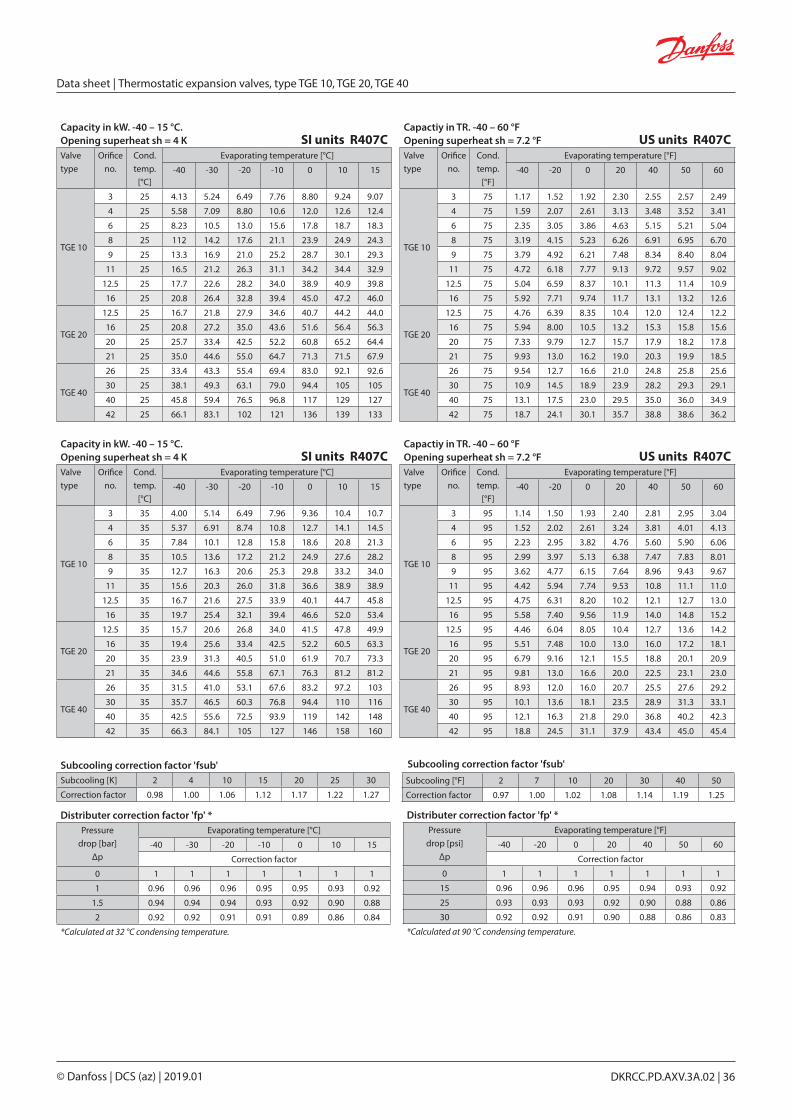
Subcooling correction factor 'fsub'Subcooling [K] 2 4 10 15 20 25 30
Correction factor 0.98 1.00 1.06 1.12 1.17 1.22 1.27
Distributer correction factor 'fp' *Pressure
drop [bar]Δp
Evaporating temperature [°C]
-40 -30 -20 -10 0 10 15
Correction factor
0 1 1 1 1 1 1 1
1 0.96 0.96 0.96 0.95 0.95 0.93 0.92
1.5 0.94 0.94 0.94 0.93 0.92 0.90 0.88
2 0.92 0.92 0.91 0.91 0.89 0.86 0.84
*Calculated at 32 °C condensing temperature.
Subcooling correction factor 'fsub'Subcooling [°F] 2 7 10 20 30 40 50
Correction factor 0.97 1.00 1.02 1.08 1.14 1.19 1.25
Distributer correction factor 'fp' *Pressure
drop [psi]Δp
Evaporating temperature [°F]
-40 -20 0 20 40 50 60
Correction factor
0 1 1 1 1 1 1 1
15 0.96 0.96 0.96 0.95 0.94 0.93 0.92
25 0.93 0.93 0.93 0.92 0.90 0.88 0.86
30 0.92 0.92 0.91 0.90 0.88 0.86 0.83
*Calculated at 90 °C condensing temperature.
Capacity in kW. -40 – 15 °C.Opening superheat sh = 4 K SI units R407CValve type
Orifice no.
Cond. temp.
[°C]
Evaporating temperature [°C]
-40 -30 -20 -10 0 10 15
TGE 10
3 25 4.13 5.24 6.49 7.76 8.80 9.24 9.07
4 25 5.58 7.09 8.80 10.6 12.0 12.6 12.4
6 25 8.23 10.5 13.0 15.6 17.8 18.7 18.3
8 25 112 14.2 17.6 21.1 23.9 24.9 24.3
9 25 13.3 16.9 21.0 25.2 28.7 30.1 29.3
11 25 16.5 21.2 26.3 31.1 34.2 34.4 32.9
12.5 25 17.7 22.6 28.2 34.0 38.9 40.9 39.8
16 25 20.8 26.4 32.8 39.4 45.0 47.2 46.0
TGE 20
12.5 25 16.7 21.8 27.9 34.6 40.7 44.2 44.0
16 25 20.8 27.2 35.0 43.6 51.6 56.4 56.3
20 25 25.7 33.4 42.5 52.2 60.8 65.2 64.4
21 25 35.0 44.6 55.0 64.7 71.3 71.5 67.9
TGE 40
26 25 33.4 43.3 55.4 69.4 83.0 92.1 92.6
30 25 38.1 49.3 63.1 79.0 94.4 105 105
40 25 45.8 59.4 76.5 96.8 117 129 127
42 25 66.1 83.1 102 121 136 139 133
Capactiy in TR. -40 – 60 °FOpening superheat sh = 7.2 °F US units R407CValve type
Orifice no.
Cond. temp.
[°F]
Evaporating temperature [°F]
-40 -20 0 20 40 50 60
TGE 10
3 75 1.17 1.52 1.92 2.30 2.55 2.57 2.49
4 75 1.59 2.07 2.61 3.13 3.48 3.52 3.41
6 75 2.35 3.05 3.86 4.63 5.15 5.21 5.04
8 75 3.19 4.15 5.23 6.26 6.91 6.95 6.70
9 75 3.79 4.92 6.21 7.48 8.34 8.40 8.04
11 75 4.72 6.18 7.77 9.13 9.72 9.57 9.02
12.5 75 5.04 6.59 8.37 10.1 11.3 11.4 10.9
16 75 5.92 7.71 9.74 11.7 13.1 13.2 12.6
TGE 20
12.5 75 4.76 6.39 8.35 10.4 12.0 12.4 12.2
16 75 5.94 8.00 10.5 13.2 15.3 15.8 15.6
20 75 7.33 9.79 12.7 15.7 17.9 18.2 17.8
21 75 9.93 13.0 16.2 19.0 20.3 19.9 18.5
TGE 40
26 75 9.54 12.7 16.6 21.0 24.8 25.8 25.6
30 75 10.9 14.5 18.9 23.9 28.2 29.3 29.1
40 75 13.1 17.5 23.0 29.5 35.0 36.0 34.9
42 75 18.7 24.1 30.1 35.7 38.8 38.6 36.2
Capacity in kW. -40 – 15 °C.Opening superheat sh = 4 K SI units R407CValve type
Orifice no.
Cond. temp.
[°C]
Evaporating temperature [°C]
-40 -30 -20 -10 0 10 15
TGE 10
3 35 4.00 5.14 6.49 7.96 9.36 10.4 10.7
4 35 5.37 6.91 8.74 10.8 12.7 14.1 14.5
6 35 7.84 10.1 12.8 15.8 18.6 20.8 21.3
8 35 10.5 13.6 17.2 21.2 24.9 27.6 28.2
9 35 12.7 16.3 20.6 25.3 29.8 33.2 34.0
11 35 15.6 20.3 26.0 31.8 36.6 38.9 38.9
12.5 35 16.7 21.6 27.5 33.9 40.1 44.7 45.8
16 35 19.7 25.4 32.1 39.4 46.6 52.0 53.4
TGE 20
12.5 35 15.7 20.6 26.8 34.0 41.5 47.8 49.9
16 35 19.4 25.6 33.4 42.5 52.2 60.5 63.3
20 35 23.9 31.3 40.5 51.0 61.9 70.7 73.3
21 35 34.6 44.6 55.8 67.1 76.3 81.2 81.2
TGE 40
26 35 31.5 41.0 53.1 67.6 83.2 97.2 103
30 35 35.7 46.5 60.3 76.8 94.4 110 116
40 35 42.5 55.6 72.5 93.9 119 142 148
42 35 66.3 84.1 105 127 146 158 160
Capactiy in TR. -40 – 60 °FOpening superheat sh = 7.2 °F US units R407CValve type
Orifice no.
Cond. temp.
[°F]
Evaporating temperature [°F]
-40 -20 0 20 40 50 60
TGE 10
3 95 1.14 1.50 1.93 2.40 2.81 2.95 3.04
4 95 1.52 2.02 2.61 3.24 3.81 4.01 4.13
6 95 2.23 2.95 3.82 4.76 5.60 5.90 6.06
8 95 2.99 3.97 5.13 6.38 7.47 7.83 8.01
9 95 3.62 4.77 6.15 7.64 8.96 9.43 9.67
11 95 4.42 5.94 7.74 9.53 10.8 11.1 11.0
12.5 95 4.75 6.31 8.20 10.2 12.1 12.7 13.0
16 95 5.58 7.40 9.56 11.9 14.0 14.8 15.2
TGE 20
12.5 95 4.46 6.04 8.05 10.4 12.7 13.6 14.2
16 95 5.51 7.48 10.0 13.0 16.0 17.2 18.1
20 95 6.79 9.16 12.1 15.5 18.8 20.1 20.9
21 95 9.81 13.0 16.6 20.0 22.5 23.1 23.0
TGE 40
26 95 8.93 12.0 16.0 20.7 25.5 27.6 29.2
30 95 10.1 13.6 18.1 23.5 28.9 31.3 33.1
40 95 12.1 16.3 21.8 29.0 36.8 40.2 42.3
42 95 18.8 24.5 31.1 37.9 43.4 45.0 45.4
Data sheet | Thermostatic expansion valves, type TGE 10, TGE 20, TGE 40
© Danfoss | DCS (az) | 2019.01 DKRCC.PD.AXV.3A.02 | 36

Subcooling correction factor 'fsub'Subcooling [K] 2 4 10 15 20 25 30
Correction factor 0.98 1.00 1.06 1.12 1.17 1.22 1.27
Distributer correction factor 'fp' *Pressure
drop [bar]Δp
Evaporating temperature [°C]
-40 -30 -20 -10 0 10 15
Correction factor
0 1 1 1 1 1 1 1
1 0.96 0.96 0.96 0.95 0.95 0.93 0.92
1.5 0.94 0.94 0.94 0.93 0.92 0.90 0.88
2 0.92 0.92 0.91 0.91 0.89 0.86 0.84
*Calculated at 32 °C condensing temperature.
Subcooling correction factor 'fsub'Subcooling [°F] 2 7 10 20 30 40 50
Correction factor 0.97 1.00 1.02 1.08 1.14 1.19 1.25
Distributer correction factor 'fp' *Pressure
drop [psi]Δp
Evaporating temperature [°F]
-40 -20 0 20 40 50 60
Correction factor
0 1 1 1 1 1 1 1
15 0.96 0.96 0.96 0.95 0.94 0.93 0.92
25 0.93 0.93 0.93 0.92 0.90 0.88 0.86
30 0.92 0.92 0.91 0.90 0.88 0.86 0.83
*Calculated at 90 °F condensing temperature.
Capacity in kW. -40 – 15 °C.Opening superheat sh = 4 K SI units R407CValve type
Orifice no.
Cond. temp.
[°C]
Evaporating temperature [°C]
-40 -30 -20 -10 0 10 15
TGE 10
3 45 3.75 4.85 6.20 7.75 9.36 10.8 11.4
4 45 4.98 6.47 8.29 10.4 12.6 14.6 15.4
6 45 7.19 9.35 12.0 15.1 18.4 21.3 22.4
8 45 9.57 12.5 16.0 20.2 24.4 28.1 29.5
9 45 11.8 15.3 19.5 24.4 29.5 33.9 35.7
11 45 14.1 18.7 24.4 30.8 36.8 40.8 41.8
12.5 45 15.2 19.9 25.7 32.4 39.3 45.4 47.7
16 45 17.9 23.4 30.1 37.8 45.8 53.1 56.0
TGE 20
12.5 45 14.3 18.8 24.6 31.7 39.7 47.4 50.8
16 45 17.5 23.1 30.3 39.3 49.4 59.5 63.8
20 45 21.5 28.3 36.8 47.2 58.9 70.1 74.8
21 45 33.1 43.2 54.8 66.9 77.8 85.4 87.6
TGE 40
26 45 28.6 37.5 49.0 63.1 79.1 95.2 103
30 45 32.3 42.4 55.4 71.5 89.6 108 116
40 45 38.3 50.2 65.9 86.6 113 141 154
42 45 64.8 82.7 104 127 150 168 174
Capactiy in TR. -40 – 60 °FOpening superheat sh = 7.2 °F US units R407CValve type
Orifice no.
Cond. temp.
[°F]
Evaporating temperature [°F]
-40 -20 0 20 40 50 60
TGE 10
3 115 1.05 1.40 1.84 2.34 2.84 3.07 3.25
4 115 1.40 1.87 2.46 3.14 3.83 4.14 4.39
6 115 2.02 2.70 3.56 4.56 5.58 6.02 6.38
8 115 2.68 3.60 4.75 6.08 7.40 7.96 8.40
9 115 3.30 4.41 5.79 7.37 8.94 9.63 10.2
11 115 3.94 5.41 7.26 9.29 11.0 11.6 11.9
12.5 115 4.27 5.76 7.63 9.78 11.9 12.9 13.6
16 115 5.02 6.76 8.92 11.4 13.9 15.1 16.0
TGE 20
12.5 115 4.01 5.43 7.31 9.64 12.2 13.4 14.5
16 115 4.90 6.66 9.02 12.0 15.2 16.8 18.2
20 115 6.02 8.15 10.9 14.3 18.0 19.8 21.3
21 115 9.33 12.5 16.3 20.0 23.2 24.3 25.0
TGE 40
26 115 8.01 10.8 14.6 19.2 24.3 26.9 29.2
30 115 9.04 12.2 16.5 21.7 27.6 30.4 33.1
40 115 10.7 14.5 19.6 26.6 35.3 39.9 44.0
42 115 18.3 24.0 30.9 38.3 45.1 47.8 49.6
Capacity in kW. -40 – 15 °C.Opening superheat sh = 4 K SI units R407CValve type
Orifice no.
Cond. temp.
[°C]
Evaporating temperature [°C]
-40 -30 -20 -10 0 10 15
TGE 10
3 55 3.39 4.41 5.68 7.20 8.86 10.5 11.2
4 55 4.46 5.82 7.54 9.59 11.8 14.1 15.0
6 55 6.35 8.31 10.8 13.8 17.1 20.3 21.7
8 55 8.36 11.0 14.3 18.2 22.6 26.7 28.5
9 55 10.4 13.6 17.7 22.5 27.7 32.7 35.0
11 55 12.2 16.4 21.9 28.3 34.8 40.1 41.8
12.5 55 13.2 17.5 23.0 29.5 36.5 43.4 46.4
16 55 15.5 20.6 26.9 34.4 42.7 51.0 54.8
TGE 20
12.5 55 12.6 16.5 21.6 28.1 35.8 43.8 47.7
16 55 15.3 20.0 26.4 34.5 44.2 54.4 59.4
20 55 18.7 24.5 32.1 41.5 52.6 64.4 70.0
21 55 30.6 40.3 51.8 64.2 75.9 85.3 88.7
TGE 40
26 55 24.9 32.8 43.1 56.1 71.3 87.7 95.8
30 55 28.0 36.9 48.6 63.4 80.7 99.1 108
40 55 33.5 43.8 57.6 76.1 101 130 145
42 55 61.5 79.0 100 124 148 169 177
Capactiy in TR. -40 – 60 °FOpening superheat sh = 7.2 °F US units R407CValve type
Orifice no.
Cond. temp.
[°F]
Evaporating temperature [°F]
-40 -20 0 20 40 50 60
TGE 10
3 135 0.94 1.25 1.66 2.15 2.68 2.93 3.16
4 135 1.23 1.65 2.20 2.86 3.58 3.92 4.24
6 135 1.74 2.35 3.14 4.10 5.15 5.66 6.11
8 135 2.29 3.10 4.15 5.42 6.78 7.43 8.01
9 135 2.85 3.86 5.16 6.70 8.35 9.14 9.87
11 135 3.32 4.64 6.39 8.44 10.4 11.2 11.80
12.5 135 3.60 4.95 6.69 8.77 11.0 12.1 13.1
16 135 4.23 5.82 7.83 10.3 12.9 14.2 15.5
TGE 20
12.5 135 3.46 4.66 6.30 8.40 10.9 12.1 13.4
16 135 4.18 5.65 7.69 10.3 13.4 15.0 16.6
20 135 5.12 6.92 9.31 12.4 15.9 17.8 19.6
21 135 8.49 11.6 15.2 19.1 22.6 24.0 25.1
TGE 40
26 135 6.80 9.24 12.5 16.7 21.6 24.2 26.8
30 135 7.63 10.4 14.1 18.9 24.5 27.4 30.3
40 135 9.16 12.4 16.8 22.9 31.1 35.9 40.7
42 135 17.2 22.7 29.5 37.1 44.5 47.7 50.3
Data sheet | Thermostatic expansion valves, type TGE 10, TGE 20, TGE 40
© Danfoss | DCS (az) | 2019.01 DKRCC.PD.AXV.3A.02 | 37

Capacity in kW. -40 – 15 °COpening superheat sh = 4 K SI units R290Valve type
Orifice no.
Cond. temp.
[°C]
Evaporating temperature [°C]
-40 -30 -20 -10 0 10 15
TGE 10
3 25 4.76 5.99 7.27 8.42 9.14 8.85 8.03
4 25 6.47 8.15 9.90 11.5 12.5 12.1 11.0
6 25 9.60 12.1 14.7 17.1 18.6 18.0 16.3
8 25 13.1 16.5 20.0 23.1 25.0 24.0 21.6
9 25 15.3 19.4 23.6 27.5 29.9 29.0 26.0
11 25 19.5 24.5 29.5 33.4 35.0 32.5 28.7
12.5 25 19.9 25.1 30.6 35.8 39.0 38.0 34.3
16 25 23.3 29.3 35.6 41.4 45.0 43.7 39.3
TGE 20
12.5 25 18.5 23.7 29.6 35.4 39.7 39.7 36.5
16 25 23.2 29.9 37.4 45.0 50.7 50.9 47.0
20 25 28.7 36.6 45.3 53.7 59.7 58.8 53.6
21 25 36.6 45.9 55.4 63.3 67.1 63.0 55.8
TGE 40
26 25 39.3 51.2 64.5 78.1 89.0 90.5 83.9
30 25 44.8 58.4 73.6 89.1 101 103 95.2
40 25 53.9 70.2 89.3 109 125 125 114
42 25 72.9 91.5 111 128 136 129 115
Capactiy in TR. -40 – 60 °FOpening superheat sh = 7.2 °F US units R290Valve type
Orifice no.
Cond. temp.
[°F]
Evaporating temperature [°F]
-40 -20 0 20 40 50 60
TGE 10
3 75 1.35 1.74 2.13 2.45 2.55 2.44 2.12
4 75 1.84 2.37 2.90 3.35 3.49 3.34 2.91
6 75 2.73 3.52 4.32 4.99 5.19 4.95 4.31
8 75 3.73 4.79 5.87 6.74 6.96 6.61 5.72
9 75 4.37 5.63 6.94 8.03 8.37 7.98 6.85
11 75 5.54 7.12 8.61 9.63 9.59 8.92 7.58
12.5 75 5.65 7.29 9.02 10.5 11.0 10.5 9.03
16 75 6.63 8.51 10.5 12.1 12.6 12.0 10.3
TGE 20
12.5 75 5.26 6.91 8.76 10.5 11.3 10.9 9.71
16 75 6.62 8.73 11.1 13.3 14.5 14.1 12.5
20 75 8.17 10.7 13.4 15.8 16.9 16.2 14.2
21 75 10.4 13.3 16.2 18.3 18.5 17.3 14.7
TGE 40
26 75 11.2 15.0 19.2 23.3 25.6 25.0 22.3
30 75 12.8 17.1 21.9 26.5 29.1 28.5 25.3
40 75 15.4 20.6 26.6 32.6 35.6 34.4 30.1
42 75 20.7 26.5 32.4 37.0 37.8 35.5 30.3
Capacity in kW. -40 – 15 °COpening superheat sh = 4 K SI units R290Valve type
Orifice no.
Cond. temp.
[°C]
Evaporating temperature [°C]
-40 -30 -20 -10 0 10 15
TGE 10
3 35 4.68 5.98 7.40 8.84 10.1 10.8 10.7
4 35 6.32 8.08 10.0 12.0 13.7 14.7 14.6
6 35 9.30 11.9 14.8 17.7 20.3 21.6 21.4
8 35 12.6 16.1 20.0 23.8 27.1 28.7 28.4
9 35 14.8 19.0 23.6 28.2 32.1 34.1 34.0
11 35 18.8 24.2 29.8 35.1 38.8 39.6 38.3
12.5 35 19.0 24.4 30.4 36.5 41.7 44.5 44.3
16 35 22.3 28.5 35.4 42.4 48.3 51.5 51.2
TGE 20
12.5 35 17.7 23.0 29.2 36.0 42.6 46.9 47.2
16 35 22.2 28.8 36.7 45.5 54.0 59.8 60.4
20 35 27.3 35.3 44.5 54.4 63.8 69.6 69.7
21 35 36.4 46.3 56.8 66.7 74.0 76.3 74.6
TGE 40
26 35 36.8 48.6 62.3 77.6 92.8 104 106
30 35 41.9 55.3 70.9 88.3 106 118 120
40 35 50.5 66.5 86.1 109 132 147 148
42 35 73.3 93.1 115 135 151 157 155
Capactiy in TR. -40 – 60 °FOpening superheat sh = 7.2 °F US units R290Valve type
Orifice no.
Cond. temp.
[°F]
Evaporating temperature [°F]
-40 -20 0 20 40 50 60
TGE 10
3 95 1.33 1.74 2.19 2.64 2.98 3.05 3.02
4 95 1.79 2.35 2.97 3.59 4.06 4.16 4.12
6 95 2.64 3.47 4.39 5.30 5.99 6.14 6.07
8 95 3.57 4.69 5.92 7.12 7.99 8.16 8.02
9 95 4.21 5.53 7.00 8.42 9.46 9.69 9.62
11 95 5.33 7.04 8.81 10.4 11.3 11.2 10.8
12.5 95 5.40 7.10 9.03 10.9 12.3 12.6 12.6
16 95 6.33 8.30 10.5 12.7 14.3 14.6 14.5
TGE 20
12.5 95 5.03 6.71 8.71 10.9 12.8 13.3 13.4
16 95 6.29 8.41 11.0 13.8 16.2 17.0 17.1
20 95 7.76 10.3 13.2 16.4 19.1 19.8 19.7
21 95 10.3 13.5 16.8 19.8 21.5 21.7 21.1
TGE 40
26 95 10.5 14.2 18.6 23.5 28.0 29.5 30.0
30 95 11.9 16.2 21.2 26.8 31.8 33.5 34.0
40 95 14.3 19.4 25.8 33.2 39.9 41.8 41.9
42 95 20.8 27.1 33.9 40.2 44.2 44.7 43.7
Subcooling correction factor 'fsub'Subcooling [K] 2 4 10 15 20 25 30
Correction factor 0.98 1.00 1.06 1.11 1.16 1.21 1.26
Distributer correction factor 'fp' *Pressure
drop [bar]Δp
Evaporating temperature [°C]
-40 -30 -20 -10 0 10 15
Correction factor
0 1 1 1 1 1 1 1
1 0.95 0.95 0.94 0.93 0.92 0.89 0.87
1.5 0.92 0.92 0.91 0.90 0.88 0.84 0.79
2 0.90 0.89 0.88 0.86 0.83 0.77 0.71
*Calculated at 32 °C condensing temperature.
Subcooling correction factor 'fsub'Subcooling [°F] 2 7 10 20 30 40 50
Correction factor 0.97 1.00 1.02 1.07 1.13 1.18 1.24
Distributer correction factor 'fp' *Pressure
drop [psi]Δp
Evaporating temperature [°F]
-40 -20 0 20 40 50 60
Correction factor
0 1 1 1 1 1 1 1
15 0.95 0.94 0.94 0.93 0.91 0.89 0.86
25 0.91 0.91 0.90 0.88 0.84 0.81 0.75
30 0.89 0.89 0.87 0.85 0.81 0.77 0.69
*Calculated at 90 °F condensing temperature.
Data sheet | Thermostatic expansion valves, type TGE 10, TGE 20, TGE 40
© Danfoss | DCS (az) | 2019.01 DKRCC.PD.AXV.3A.02 | 38

Capacity in kW. -40 – 15 °COpening superheat sh = 4 K SI units R290Valve type
Orifice no.
Cond. temp.
[°C]
Evaporating temperature [°C]
-40 -30 -20 -10 0 10 15
TGE 10
3 45 4.48 5.78 7.25 8.85 10.4 11.7 12.1
4 45 6.00 7.76 9.76 11.9 14.1 15.9 16.4
6 45 8.73 11.3 14.3 17.5 20.7 23.2 24.0
8 45 11.7 15.2 19.2 23.4 27.6 30.8 31.6
9 45 13.8 18.0 22.7 27.7 32.5 36.2 37.4
11 45 17.5 23.0 29.0 35.0 40.3 43.4 43.7
12.5 45 17.5 22.8 29.0 35.7 42.0 46.9 48.5
16 45 20.6 26.7 33.9 41.5 48.8 54.6 56.5
TGE 20
12.5 45 16.5 21.6 27.7 34.8 42.4 49.2 51.7
16 45 20.5 26.8 34.5 43.6 53.4 62.3 65.6
20 45 25.3 32.9 41.9 52.4 63.4 73.2 76.6
21 45 35.0 45.1 56.3 67.4 76.9 83.0 84.2
TGE 40
26 45 33.5 44.6 57.8 73.3 90.3 107 113
30 45 37.9 50.6 65.6 83.2 103 121 128
40 45 45.8 60.8 79.7 103 130 155 163
42 45 71.5 91.8 115 138 158 172 175
Capactiy in TR. -40 – 60 °FOpening superheat sh = 7.2 °F US units R290Valve type
Orifice no.
Cond. temp.
[°F]
Evaporating temperature [°F]
-40 -20 0 20 40 50 60
TGE 10
3 115 1.26 1.67 2.15 2.66 3.14 3.33 3.46
4 115 1.69 2.25 2.89 3.59 4.25 4.52 4.70
6 115 2.46 3.28 4.23 5.26 6.23 6.62 6.87
8 115 3.30 4.40 5.67 7.02 8.28 8.76 9.06
9 115 3.88 5.19 6.72 8.31 9.74 10.3 10.7
11 115 4.91 6.65 8.57 10.5 12.0 12.4 12.5
12.5 115 4.92 6.60 8.59 10.7 12.6 13.3 13.9
16 115 5.78 7.73 10.0 12.4 14.7 15.5 16.2
TGE 20
12.5 115 4.65 6.24 8.22 10.5 12.9 14.0 14.8
16 115 5.76 7.76 10.3 13.2 16.3 17.7 18.8
20 115 7.10 9.51 12.4 15.8 19.3 20.8 21.9
21 115 9.89 13.1 16.6 20.1 22.8 23.7 24.1
TGE 40
26 115 9.39 12.9 17.2 22.2 27.6 30.2 32.2
30 115 10.6 14.6 19.5 25.2 31.4 34.2 36.5
40 115 12.8 17.6 23.7 31.5 40.1 43.9 46.7
42 115 20.2 26.7 33.9 41.2 47.1 49.1 50.3
Capacity in kW. -40 – 15 °COpening superheat sh = 4 K SI units R290Valve type
Orifice no.
Cond. temp.
[°C]
Evaporating temperature [°C]
-40 -30 -20 -10 0 10 15
TGE 10
3 55 4.16 5.42 6.87 8.49 10.2 11.8 12.5
4 55 5.54 7.23 9.19 11.4 13.7 15.9 16.8
6 55 7.97 10.4 13.3 16.5 19.9 23.1 24.4
8 55 10.6 13.9 17.7 22.0 26.4 30.5 32.2
9 55 12.4 16.3 21.0 26.1 31.3 35.9 37.9
11 55 15.7 21.1 27.1 33.4 39.5 44.2 45.5
12.5 55 15.5 20.5 26.5 33.2 40.1 46.3 48.9
16 55 18.2 24.0 31.0 38.8 46.8 54.2 57.4
TGE 20
12.5 55 15.0 19.7 25.3 32.2 39.9 47.8 51.3
16 55 18.5 24.3 31.4 40.0 49.9 60.0 64.7
20 55 22.7 29.7 38.2 48.2 59.5 71.0 76.1
21 55 32.6 42.6 53.8 65.4 76.2 84.6 87.6
TGE 40
26 55 29.5 39.6 51.8 66.3 83.1 101 110
30 55 33.3 44.7 58.6 75.1 94.1 114 124
40 55 40.3 53.6 70.8 93.0 120 150 163
42 55 67.8 87.8 111 135 158 177 184
Capactiy in TR. -40 – 60 °FOpening superheat sh = 7.2 °F US units R290Valve type
Orifice no.
Cond. temp.
[°F]
Evaporating temperature [°F]
-40 -20 0 20 40 50 60
TGE 10
3 135 1.16 1.55 2.01 2.53 3.07 3.32 3.54
4 135 1.54 2.07 2.69 3.40 4.14 4.48 4.78
6 135 2.21 2.98 3.89 4.93 6.00 6.50 6.94
8 135 2.93 3.96 5.17 6.54 7.94 8.58 9.11
9 135 3.39 4.64 6.12 7.76 9.37 10.1 10.8
11 135 4.34 6.02 7.93 9.94 11.8 12.5 13.0
12.5 135 4.25 5.81 7.73 9.88 12.0 13.0 13.9
16 135 4.99 6.81 9.03 11.5 14.1 15.2 16.3
TGE 20
12.5 135 4.16 5.60 7.42 9.62 12.1 13.4 14.5
16 135 5.11 6.90 9.18 12.0 15.1 16.8 18.3
20 135 6.28 8.46 11.1 14.4 18.0 19.8 21.5
21 135 9.06 12.2 15.8 19.4 22.7 24.0 25.0
TGE 40
26 135 8.10 11.3 15.1 19.8 25.3 28.1 30.8
30 135 9.12 12.7 17.1 22.4 28.6 31.8 34.9
40 135 11.1 15.2 20.7 28.0 37.0 41.7 46.1
42 135 18.9 25.3 32.6 40.2 47.2 50.1 52.4
Subcooling correction factor 'fsub'Subcooling [K] 2 4 10 15 20 25 30
Correction factor 0.98 1.00 1.06 1.11 1.16 1.21 1.26
Distributer correction factor 'fp' *Pressure
drop [bar]Δp
Evaporating temperature [°C]
-40 -30 -20 -10 0 10 15
Correction factor
0 1 1 1 1 1 1 1
1 0.95 0.95 0.94 0.93 0.92 0.89 0.87
1.5 0.92 0.92 0.91 0.90 0.88 0.84 0.79
2 0.90 0.89 0.88 0.86 0.83 0.77 0.71
*Calculated at 32 °C condensing temperature.
Subcooling correction factor 'fsub'Subcooling [°F] 2 7 10 20 30 40 50
Correction factor 0.97 1.00 1.02 1.07 1.13 1.18 1.24
Distributer correction factor 'fp' *Pressure
drop [psi]Δp
Evaporating temperature [°F]
-40 -20 0 20 40 50 60
Correction factor
0 1 1 1 1 1 1 1
15 0.95 0.94 0.94 0.93 0.91 0.89 0.86
25 0.91 0.91 0.90 0.88 0.84 0.81 0.75
30 0.89 0.89 0.87 0.85 0.81 0.77 0.69
*Calculated at 90 °F condensing temperature.
Data sheet | Thermostatic expansion valves, type TGE 10, TGE 20, TGE 40
© Danfoss | DCS (az) | 2019.01 DKRCC.PD.AXV.3A.02 | 39

Dimensions and weight in SI unitsType Connections. ODF solder
inlet x outlet x equalizationCapillary
tube lengthH1 H2 H3 H4 L1 L2 L3 L4 ØD1 ØD2 A B C Weight
[in.] [mm] [m] [mm] [mm] [mm] [mm] [mm] [mm] [mm] [mm] [mm] [mm] [mm] [mm] [mm] [kg]
TGE 10
3⁄8 x 5⁄8 x 1⁄4 10 x 16 x 6 1.5 28.5 7.5 5.0 93.0 41.5 45.5 37.0 70 45 14.35 9.0 12 7 0.371⁄2 x 5⁄8 x 1⁄4 12 x 16 x 6 1.5 28.5 7.5 5.0 93.0 41.5 45.5 37.0 70 45 14.35 10 12 7 0.371⁄2 x 7⁄8 x 1⁄4 12 x 22 x 6 1.5 28.5 7.5 5.0 93.0 41.5 59.5 37.0 70 45 14.35 10 17 7 0.375⁄8 x 5⁄8 x 1⁄4 16 x 16 x 6 1.5 28.5 7.5 5.0 93.0 45.5 45.5 37.0 70 45 14.35 12 12 7 0.375⁄8 x 7⁄8 x 1⁄4 16 x 22 x 6 1.5 28.5 7.5 5.0 93.0 45.5 59.5 37.0 70 45 14.35 12 17 7 0.37
5⁄8 x 1 1⁄8 x 1⁄4 16 x 28 x 6 1.5 28.5 7.5 5.0 93.0 45.5 59.5 37.0 70 45 14.35 12 20 7 0.377⁄8 x 7⁄8 x 1⁄4 22 x 22 x 6 1.5 28.5 7.5 5.0 93.0 45.5 59.5 37.0 70 45 14.35 12 17 7 0.37
7⁄8 x 1 1⁄8 x 1⁄4 22 x 28 x 6 1.5 28.5 7.5 5.0 93.0 45.5 59.5 37.0 70 45 14.35 12 20 7 0.37
TGE 20
5⁄8 x 5⁄8 x 1⁄4 16 x 16 x 6 1.5 32.0 9.0 8.0 121 48.0 62.0 40.5 78 53 19.20 12 12 7 0.575⁄8 x 7⁄8 x 1⁄4 16 x 22 x 6 1.5 32.0 9.0 8.0 121 48.0 62.0 40.5 78 53 19.20 12 17 7 0.57
5⁄8 x 1 1⁄8 x 1⁄4 16 x 28 x 6 1.5 32.0 9.0 8.0 121 48.0 66.0 40.5 78 53 19.20 12 20 7 0.577⁄8 x 7⁄8 x 1⁄4 22 x 22 x 6 1.5 32.0 9.0 8.0 121 62.0 62.0 40.5 78 53 19.20 17 17 7 0.57
7⁄8 x 1 1⁄8 x 1⁄4 22 x 28 x 6 1.5 32.0 9.0 8.0 121 62.0 66.0 40.5 78 53 19.20 17 20 7 0.577⁄8 x 1 3⁄8 x 1⁄4 22 x 35 x 6 1.5 32.0 9.0 8.0 121 62.0 66.0 40.5 78 53 19.20 17 24 7 0.57
1 1⁄8 x 1 1⁄8 x 1⁄4 28 x 28 x 6 1.5 32.0 9.0 8.0 121 62.0 66.0 40.5 78 53 19.20 20 20 7 0.57
1 1⁄8 x 1 3⁄8 x 1⁄4 28 x 35 x 6 1.5 32.0 9.0 8.0 121 62.0 66.0 40.5 78 53 19.20 20 24 7 0.57
TGE 40
7⁄8 x 7⁄8 x 1⁄4 22 x 22 x 6 3 39.0 15 11 148 65.5 69.5 43.5 78 60 19.20 17 20 7 0.937⁄8 x 1 1⁄8 x 1⁄4 22 x 28 x 6 3 39.0 15 11 148 65.5 69.5 43.5 78 60 19.20 17 20 7 0.937⁄8 x 1 3⁄8 x 1⁄4 22 x 35 x 6 3 39.0 15 11 148 65.5 74.5 43.5 78 60 19.20 17 25 7 0.93
1 1⁄8 x 1 1⁄8 x 1⁄4 28 x 28 x 6 3 39.0 15 11 148 69.5 69.5 43.5 78 60 19.20 20 20 7 0.93
1 1⁄8 x 1 3⁄8 x 1⁄4 28 x 35 x 6 3 39.0 15 11 148 69.5 74.5 43.5 78 60 19.20 20 25 7 0.93
B
A
L2 L1
H4
H1H3
H2
ØD1
ØD2
L4
L3
C
Danfoss67N50.10
Dimensions and weights
Data sheet | Thermostatic expansion valves, type TGE 10, TGE 20, TGE 40
© Danfoss | DCS (az) | 2019.01 DKRCC.PD.AXV.3A.02 | 40

Dimensions and weights
Dimensions and weight in US unitsType Connections. ODF solder
inlet x outlet x equalizationCapillary
tube lengthH1 H2 H3 H4 L1 L2 L3 L4 ØD1 ØD2 A B C Weight
[in.] [mm] [in.] [in] [in.] [in.] [in.] [in.] [in.] [in.] [in.] [in.] [in.] [in.] [in.] [in.] [lbs]
TGE 10
3/8 x 5/8 x 1/4 10 x 16 x 6 59 1.12 0.30 0.20 3.66 1.63 1.79 1.46 2.76 1.77 0.56 0.36 0.48 0.28 0.81
1/2 x 5/8 x 1/4 12 x 16 x 6 59 1.12 0.30 0.20 3.66 1.63 1.79 1.46 2.76 1.77 0.56 0.39 0.48 0.28 0.81
1/2 x 7/8 x 1/4 12 x 22 x 6 59 1.12 0.30 0.20 3.66 1.63 2.34 1.46 2.76 1.77 0.56 0.39 0.66 0.28 0.81
5/8 x 5/8 x 1/4 16 x 16 x 6 59 1.12 0.30 0.20 3.66 1.79 1.79 1.46 2.76 1.77 0.56 0.48 0.48 0.28 0.81
5/8 x 7/8 x 1/4 16 x 22 x 6 59 1.12 0.30 0.20 3.66 1.79 2.34 1.46 2.76 1.77 0.56 0.48 0.66 0.28 0.81
5/8 x 1 1/8 x 1/4 16 x 28 x 6 59 1.12 0.30 0.20 3.66 1.79 2.34 1.46 2.76 1.77 0.56 0.48 0.78 0.28 0.81
7/8 x 7/8 x 1/4 22 x 22 x 6 59 1.12 0.30 0.20 3.66 1.79 2.34 1.46 2.76 1.77 0.56 0.48 0.66 0.28 0.81
7/8 x 1 1/8 x 1/4 22 x 28 x 6 59 1.12 0.30 0.20 3.66 1.79 2.34 1.46 2.76 1.77 0.56 0.48 0.78 0.28 0.81
TGE 20
5/8 x 5/8 x 1/4 16 x 16 x 6 59 1.26 0.35 0.31 4.76 1.89 2.44 1.59 3.07 2.09 0.76 0.48 0.48 0.28 1.27
5/8 x 7/8 x 1/4 16 x 22 x 6 59 1.26 0.35 0.31 4.76 1.89 2.44 1.59 3.07 2.09 0.76 0.48 0.66 0.28 1.27
5/8 x 1 1/8 x 1/4 16 x 28 x 6 59 1.26 0.35 0.31 4.76 1.89 2.6 1.59 3.07 2.09 0.76 0.48 0.78 0.28 1.27
7/8 x 7/8 x 1/4 22 x 22 x 6 59 1.26 0.35 0.31 4.76 2.44 2.44 1.59 3.07 2.09 0.76 0.66 0.66 0.28 1.27
7/8 x 1 1/8 x 1/4 22 x 28 x 6 59 1.26 0.35 0.31 4.76 2.44 2.6 1.59 3.07 2.09 0.76 0.66 0.78 0.28 1.27
7/8 x 1 3/8 x 1/4 22 x 35 x 6 59 1.26 0.35 0.31 4.76 2.44 2.6 1.59 3.07 2.09 0.76 0.66 0.98 0.28 1.27
1 1/8 x 1 1/8 x 1/4 28 x 28 x 6 59 1.26 0.35 0.31 4.76 2.44 2.6 1.59 3.07 2.09 0.76 0.78 0.78 0.28 1.27
1 1/8 x 1 3/8 x 1/4 28 x 35 x 6 59 1.26 0.35 0.31 4.76 2.44 2.6 1.59 3.07 2.09 0.76 0.78 0.98 0.28 1.27
TGE 40
7/8 x 7/8 x 1/4 22 x 22 x 6 118 1.54 0.59 0.43 5.83 2.58 2.74 1.71 3.07 2.36 0.76 0.66 0.78 0.28 2.05
7/8 x 1 1/8 x 1/4 22 x 28 x 6 118 1.54 0.59 0.43 5.83 2.58 2.74 1.71 3.07 2.36 0.76 0.66 0.78 0.28 2.05
7/8 x 1 3/8 x 1/4 22 x 35 x 6 118 1.54 0.59 0.43 5.83 2.58 2.93 1.71 3.07 2.36 0.76 0.66 0.98 0.28 2.05
1 1/8 x 1 1/8 x 1/4 28 x 28 x 6 118 1.54 0.59 0.43 5.83 2.74 2.74 1.71 3.07 2.36 0.76 0.78 0.78 0.28 2.05
1 1/8 x 1 3/8 x 1/4 28 x 35 x 6 118 1.54 0.59 0.43 5.83 2.74 2.93 1.71 3.07 2.36 0.76 0.78 0.98 0.28 2.05
B
A
L2 L1
H4
H1H3
H2
ØD1
ØD2
L4
L3
C
Danfoss67N50.10
© Danfoss | DCS (az) | 2019.01 DKRCC.PD.AXV.3A.02 | 41