Embed Size (px)
Citation preview
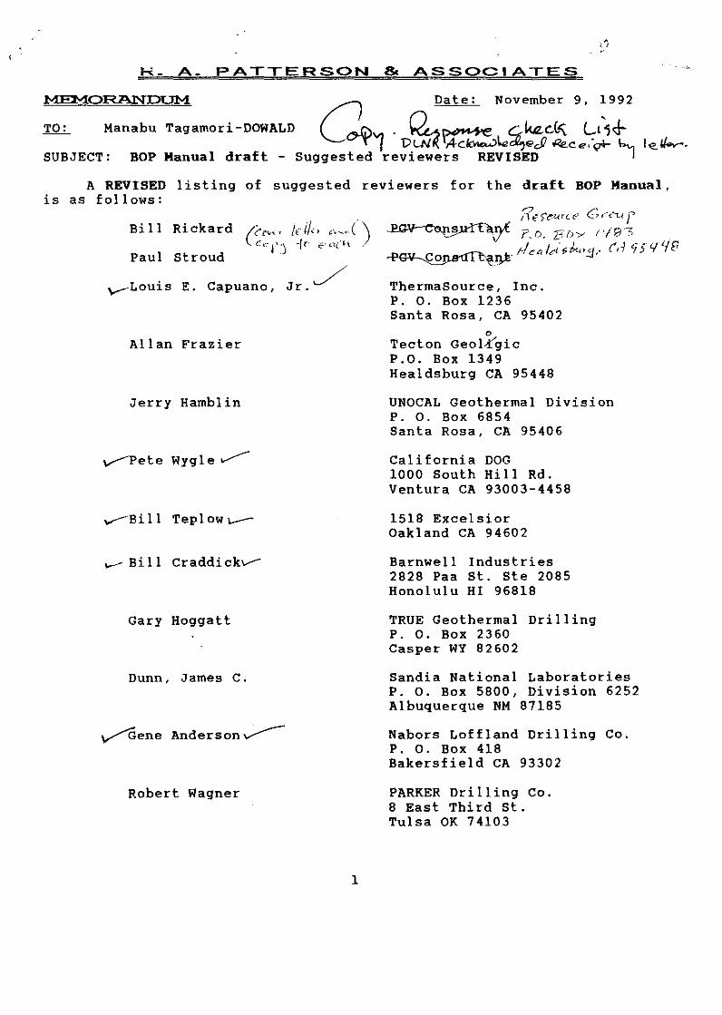
R- A- PATTERSON & ASSOCIATES
Manabu Tagamori-DOWALD a Date: November 9, ~992
SUBJECT: BOP
...._[,) . Q_ . ~ c::;..ktz.d" Lt1¢. "''t'f P~ ,4ctc-..:>k'*'?e.Jl Re.ce:~ \,_, Manual draft - Suggested reviewers REVISED I
A REVISED listing of suggested reviewers for the draft BOP Manual, is as follows:
Bill Rickard
Paul Stroud
y-Louis E. Capuano, Jr./
Allan Frazier
Jerry Hamblin
v-<>ete Wygle ,.....----
_.-Bi 11 Tepl ow~
...-- Bi 11 Craddi ckv-
Gary Hoggatt
Dunn, James c.
~ene Anderson~
Robert Wagner
1
ThermaSource, Inc. P. 0. Box 1236 Santa Rosa, CA 95402
0
Tecton GeoV(gic P.O. Box 1349 Healdsburg CA 95448
UNOCAL Geothermal Division P. 0. Box 6854 Santa Rosa, CA 95406
California DOG 1000 South Hill Rd. Ventura CA 93003-4458
1518 Excelsior Oakland CA 94602
Barnwell Industries 2828 Paa St. Ste 2085 Honolulu HI 96818
TRUE Geothermal Drilling P. 0. Box 2360 Casper WY 82602
Sandia National Laboratories P. 0. Box 5800, Division 6252 Albuquerque NM 87185
Nabors Loffland Drilling Co. P. 0. Box 418 Bakersfield CA 93302
PARKER Drilling Co. 8 East Third st. Tulsa OK 74103

f
~ Richard Thomas
'~.t. ~""'.......,(~ 17e-k wy,le ~ V'"' "' f'""" ~
Bowen E. Roberts
Geothermal Officer California DOG 801 K Street - MS 22 Sacramento CA 95814-3530
ARCO Oil & Gas 4550 California Ave. Bakersfield CA 93309
We have not included any Hawaii State or County officials, as many of these will likely see the draft anyway. A possible draft cover letter is attached.
If there are any questions about the above list, or if we can provide more information on possible reviewers, please call.
2

• R_ A- PATTERSON & ASSOCIATES
Date: November 9, 1992
TO: Manabu Tagamori-DOWALD
SUBJECT: BOP Manual draft - Suggested reviewers REVISED
A REVISED listing of suggested reviewers for the draft BOP Manual, is as follows:
Bill Rickard ('""' ~ti/. . .. _.( ). ( ,.- ~' ") ·/l < ~-.,: ~ l
Stroud · Paul
Louis E. Capuano, Jr.
Allan Frazier
Jerry Hamblin
Pete Wygle
Bill Tepl ow
Bill Craddick
Gary Hoggatt
Dunn, James C.
Gene Anderson
Robert Wagner
1
ThermaSource, Inc. P. o. Box 1236 Santa Rosa, CA 95402
" Tecton Geol-r'gic P.O. Box 1349 Healdsburg CA 95448
UNOCAL Geothermal Division P. 0. Box 6854 Santa Rosa, CA 95406
California DOG 1000 South Hill Rd. Ventura CA 93003-4458
1518 Excelsior Oakland CA 94602
Barnwell Industries 2828 Paa St. Ste 2085 Honolulu HI 96818
TRUE Geothermal Drilling P. 0. Box 2360 Casper WY 82602
Sandia National Laboratories P. 0. Box 5800, Division 6252 Albuquerque NM 87185
Nabors Loffland Drilling Co. P. 0. Box 418 Bakersfield CA 93302
PARKER Drilling Co. 8 East Third St. Tulsa OK 74103

Richard Thomas
Bowen E. Roberts
Geothermal Officer California DOG 801 K Street - MS 22 Sacramento CA 95814-3530
ARCO Oil & Gas 4550 California Ave. Bakersfield CA 93309
We have not included any Hawaii State or County officials, as many of these will likely see the draft anyway. A possible draft cover letter is attached.
If there are any questions about the above list, or if we can provide more information on possible reviewers, please call.
2

-JO~IN WAIHEE
GOVERNOR OF HAWAII
~F1 ~
Dear ~F2 ~:
~~}-~~-~~--~-;~~~~---.
~~-~) STATE OF HAWAII
DEPARTMENT OF LAND AND NATURAL RESOURCES DIVISION OF WATER AND LAND DEVELOPMENT
P. 0 fiOX 373
HONOLULU, IIAWAII 961:109
DEC -4 1992
,'-.. ,_/ {_ 0-r--·--l ' .
WILLIAM W PATY, CHAIRPERSON
BOAR[} OF LANO ANO NATURAl RESOURCES
[)EPUII~S
JOHN P. KEPPELF=R, II DONA L. HANAIKE
AQUACULTURE DEVELOPMENT PROGRAM
AQUATIC RESOURCES
CONSERVATION AND ENVIRONMENTAl AFrAIRS
!"":ONSERVATION AND RESOIJRCfS ENFORCEMErH
C'ONVErMKES fORESTRY AND WILDLirf HISIOfliC f'RESERvAriON
f'HO(;PM,1
LAND MIIN.~r,EMfNI .5\AI( P/lni'.S
1'1/ITER liND L/ltJD D~','f~OPMft-H
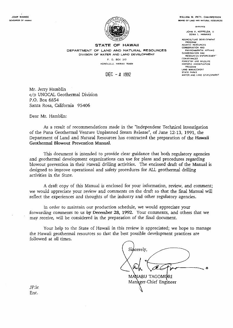
As a result of recommendations made in the "Independent Technical Investigation of the Puna Geothermal Venture Unplanned Steam Release", of June 12-13, 1991, the Department of Land and Natural Resources has contracted the preparation of the Hawaii Geothermal Blowout Prevention Manual.
This document is intended to provide clear guidance that both regulatory agencies and geothermal development organizations can use for plans and procedures regarding blowout prevention in their Hawaii drilling activities. The enclosed draft of the Manual is designed to improve operational and safety procedures for ALL geothermal drilling activities in the State.
A draft copy of this Manual is enclosed for your information, review, and comment; we would appreciate your review and comments on the draft so that the final Manual will reflect the exp<';riences and thoughts of the industry and other regulatory agencies.
In order to maintain our production schedule, we would appreciate your forwarding comments to us by December 28, 1992. Your comments, and others that we may receive, will be considered in the preparation of the final document.
Your help to the State of Hawaii in this review is appreciated; we hope to manage the Hawaii geothermal resources so that the best possible development practices are followed at all times.
JF:lc En c.
me rely, /------~------._
MA BU TAGOMO {I er-Chief Eng· eer
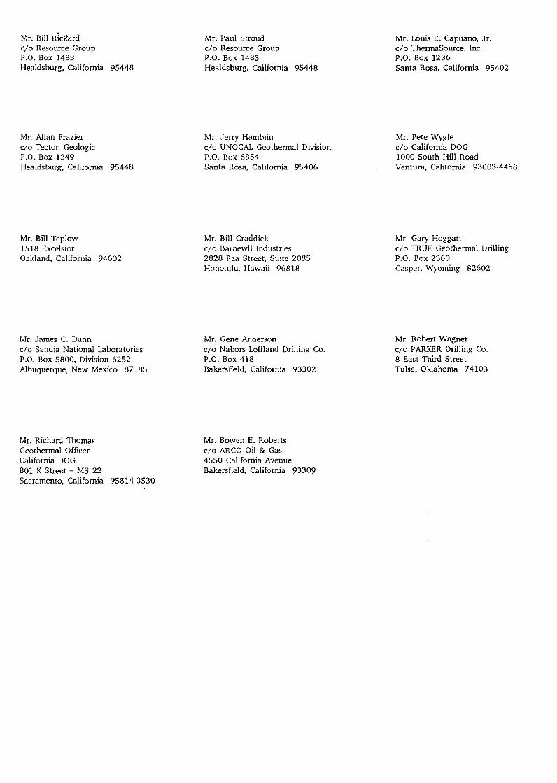
Mr. Bill Rlcitard cjo Resource Group P.O. Box 1483 Healdsburg, California 95448
Mr. Allan Frazier cjo Tecton Geologic P.O. Box 1349 Healdsburg, California 95448
Mr. Bill Teplow 1518 Excelsior Oakland, California 94602
Mr. James C. Dunn cjo Sandia National Laboratories P .0. Box 5800, Division 6252 Albuquerque, New Mexico 87185
Mr. Richard Thomas Geothermal Officer California DOG 801 K Street - MS 22 Sacramento, California 95814·3530
Mr. Paul Stroud c/o Resource Group P.O. Box 1483 Healdsburg, California 95448
Mr. Jerry Hamblin c/o UNOCAL Geothermal Division P.O. Box 6854 Santa Rosa, California 95406
Mr. Bill Craddick c/o Barnewll Industries 2828 Paa Street, Suite 2085 Honolulu, Hawaii 96818
Mr. Gene Anderson c/o Nabors Loffland Drilling Co. P.O. Box 418 Bakersfield, California 93302
Mr. Bowen E. Roberts c/o ARCO Oil & Gas 4550 California Avenue Bakersfield, California 93309
Mr. Louis E. Capuano, Jr. c/o ThermaSource, Inc. P .0. Box 1236 Santa Rosa, California 95402
Mr. Pete Wygle c/o California DOG 1000 South Hill Road Ventura, California 93003-4458
Mr. Gary Hoggatt c/o TRUE Geothermal Drilling P.O. Box 2360 Casper, Wyoming 82602
Mr. Robert Wagner c/o PARKER Drilling Co. 8 East Third Street Tulsa, Oklahoma 74103

.JOHN WAIHEE
GOVERNOR OF HAWAII
STATE OF HAWAII DEPARTMENT OF LAND AND NATURAL RESOURCES
DIVISION OF WATER AND LAND DEVELOPMENT
Mr. Bill Rickard c/p Resource Group P.O. Box 1483 Healdsburg, California 95448
Dear Mr. Rickard:
P. 0. BOX 373
HONOLULU, HAWAII 96809
DEC -4 1992
WILLIAM W. PATY, CHAIRPERSON
90ARO OF LAND AND NATURAl flESOURCES
DEPUTIES
JOHN P. KEPPELER, II DONA l. HANAIKE
AQUACULTURE DEVELOPMENT PROGRAM
AQUATIC RESOURCES CONSERVATION AND
ENVIRONMENTAL AFFAIRS CONSERVATION AND
RESOURCES ENFORCEMENT CONVEYANCES FORESTRY AND WILDLIFE
HISTORIC PRESEAVATION PROGRAM
LAND MANAGEMENT
STATE PARKS
WATER AND LAND DEVELOPMENT
A5 a result of recommendations made in the "Independent Technical Investigation of the Puna Geothermal Venture Unplanned Steam Release", of June 12-13, 1991, the Department of Land and Natural Resources has contracted the preparation of the Hawaii Geothermal Blowout Prevention Manual.
This document is intended to provide clear guidance that both regulatory agencies and geothermal development organizations can use for plans and procedures regarding blowout prevention in their Hawaii drilling activities. The enclosed draft of the Manual is designed to improve operational and safety procedures for ALL geothermal drilling activities in the State.
A draft copy of this Manual is enclosed for your information, review, and comment; we would appreciate your review and comments on the draft so that the frnal Manual will reflect the experiences and thoughts of the industry and other regulatory agencies.
In order to maintain our production schedule, we would appreciate your forwarding comments to us by December 28, 1992. Your comments, and others that we may receive, will be considered in the preparation of the frnal document.
Your help to the State of Hawaii in this review is appreciated; we hope to manage the Hawaii geothermal resources so that the best possible development practices are followed at all times.
JF:lc En c.
~[c;;;?_ M UTA~! Man er-Chi~~~~~!eer

JOHN WAIHEE
GOVERNOR OF HAWAU
STATE OF HAWAII DEPARTMENT OF LAND AND NATURAL RESOURCES
DIVISION OF WATER AND LAND DEVELOPMENT
Mr. Paul Stroud c/o Resource Group P.O. Box 1483 Healdsburg, California 95448
Dear Mr. Stroud:
P. 0. BOX 373
HONOLULU, HAWAII 96809
DEC -4 1992
WILLIAM W. f>ATY, CHAIRPERSON
90ARO OF LAND AND NATURAL RESOURCES
DEPUTIES
JOHN P. KEPPELER. II DONA L. HANAIKE
AQUACULTURE DEVELOPMENT
PROGRAM AQUATIC RESOURCES CONSERVATION AND
ENVIRONMENTAL AFFAIRS CONSERVATION AND
RESOURCES ENFORCEMENT
CONVEYANCES FORESTRY AND WILDLIFE HISTORIC PRESERVATION
PROGRAM
LAND MANAGEMENT STATE PARKS WATER AND LAND DEVELOPMENT
As a result of recommendations made in the "Independent Technical Investigation of the Puna Geothermal Venture Unplanned Stearn Release", of June 12-13, 1991, the Department of Land and Natural Resources has contracted the preparation of the Hawaii Geothermal Blowout Prevention Manual.
This document is intended to provide clear guidance that both regulatory agencies and geothermal development organizations can use for plans and procedures regarding blowout prevention in their Hawaii drilling activities. The enclosed draft of the Manual is designed to improve operational and safety procedures for ALL geothermal drilling activities in the State.
A draft copy of this Manual is enclosed for your information, review, and comment; we would appreciate your review and comments on the draft so that the fmal Manual will reflect the experiences and thoughts of the industry and other regulatory agencies.
In order to maintain our production schedule, we would appreciate your forwarding comments to us by December 28, 1992. Your comments, and others that we may receive, will be considered in the preparation of the final document.
Your help to the State of Hawaii in this review is appreciated; we hope to manage the Hawaii geothermal resources so that the best possible development practices are followed at all times.
JF:lc En c.
RI er -Chief Engineer

JOHN WAIHEE
GOVERNOR OF liAWAII
STATE OF HAWAII
DEPARTMENT OF LAND AND NATURAL RESOURCES DIVISION OF WATER AND LAND DEVELOPMENT
Mr. Louis E. Capuano, Jr. c/o ThermaSource, Inc. P.O. Box 1236 Santa Rosa, California 95402
Dear Mr. Capuano:
P. 0. BOX 373
HONOLULU, HAWAll 96809
DEC -4 1992
WILLIAM W. PATY. CHAIRPERSON
BOAAO OF LANO ANO NATURAl RESOURCES
DEPUTIES
JOHN P. KEPPELER, Jl DONA L. HANAIKE
AQUACULTURE DEVElOPMENT PROGRAM
AQUATIC RESOURCES
CONSERVATION AND ENVIRONMENTAl AFFAIRS
CONSERVATION AND
RESOURCES ENFORCEMENT CONVEYANCES FORESTRY AND WILDLIFE HISTORIC PRESERVATION
PROGRAM
LAND MANAGEMENT STATE PARKS
WATER AND LAND DEVELOPMENT
As a result of recommendations made in the "Independent Technical Investigation of the Puna Geothermal Venture Unplanned Steam Release", of June 12-13, 1991, the Department of Land and Natural Resources has contracted the preparation of the Hawaii Geothermal Blowout Prevention Manual.
This document is intended to provide clear guidance that both regulatory agencies and geothermal development organizations can use for plans and procedures regarding blowout prevention in their Hawaii drilling activities. The enclosed draft of the Manual is designed to improve operational and safety procedures for ALL geothermal drilling activities in the State.
A draft copy of this Manual is enclosed for your information, review, and comment; we would appreciate your review and comments on the draft so that the final Manual will reflect the experiences and thoughts of the industry and other regulatory agencies.
In order to maintain our production schedule, we would appreciate your forwarding comments to us by December 28, 1992. Your comments, and others that we may receive, will be considered in the preparation of the final document.
Your help to the State of Hawaii in this review is appreciated; we hope to manage the Hawaii geothermal resources so that the best possible development practices are followed at all times.
JF:lc En c.
--------------,~

JOHN WAIHEE
GOVERNOR OF HAWAtt
STATE OF HAWAII
DEPARTMENT OF LAND AND NATURAL RESOURCES DIVISION OF WATER AND LAND DEVELOPMENT
Mr. Allan Frazier c! o Tecton Geologic P.O. Box 1349 Healdsburg, California 95448
Dear Mr. Frazier:
P. 0. BOX 373
HONOLULU. HAWAII 96809
DEC - 4 1992
WILLIAM W. PATY, CHAIRPERSON
BOARO OF LAND AND NATURAL RESOURCES
DEPUTIES
JOHN P. KEPPELER, II
DONA L. HANAIKE
AQUACULTURE DEVELOPMENT
PROGRAM AQUATIC RESOURCES
CONSERVATION AND
ENVIRONMENTAL AFFAIRS CONSERVATION AND
RESOURCES ENFORCEMENT
CONVEYANCES FORESTRY AND WILDLIFE
HISTORIC PRESERVATION PROGRAM
LAND MANAGEMENT
STATE PARKS WATER AND LAND DEVELOPMENT
As a result of recommendations made in the "Independent Technical Investigation of the Puna Geothermal Venture Unplanned Steam Release", of June 12-13, 1991, the Department of Land and Natural Resources has contracted the preparation of the Hawaii Geothermal Blowout Prevention Manual.
This document is intended to provide clear guidance that both regulatory agencies and geothermal development organizations can use for plans and procedures regarding blowout prevention in their Hawaii drilling activities. The enclosed draft of the Manual is designed to improve operational and safety procedures for ALL geothermal drilling activities in the State.
A draft copy of this Manual is enclosed for your information, review, and comment; we would appreciate your review and comments on the draft so that the fmal Manual will reflect the experiences and thoughts of the industry and other regulatory agencies.
In order to maintain our production schedule, we would appreciate your forwarding comments to us by December 28, 1992. Your comments, and others that we may receive, will be considered in the preparation of the final document.
Your help to the State of Hawaii in this review is appreciated; we hope to manage the Hawaii geothermal resources so that the best possible development practices are followed at all times.
JF:lc En c.
JOHN WAIHEE
GOVERNOR OF MAWAII
STATE OF HAWAII
DEPARTMENT OF LAND AND NATURAL RESOURCES
DIVISION OF WATER AND LAND DEVELOPMENT
Mr. Jerry Hamblin c/9 UNOCAL Geothermal Division P.O. Box 6854 Santa Rosa, California 95406
Dear Mr. Hamblin:
P. 0. BOX 373
HONOLULU, HAWAII 96809
DEC -4 1992
WILLIAM W. PATY, CHAIRPERSON
BOARD OF LANO AND NATURAL RESOURCES
DEPUTIES
JOHN P. KEPPELER, II DONA L. HANAIKE
AQUACULTURE DEVELOPMENT PROGRAM
AQUATIC RESOURCES
CONSERVATION AND
ENVIRONMENTAL AFFAIRS CONSERVATION AND
RESOURCES ENFORCEMENT
CONVEYANCES FORESTRY AND WILDLIFE
HISTORIC PRESERVATION PROGRAM
LAND MANAGEMENT
STATE PARKS WATER AND LAND DEVELOPMENT
As a result of recommendations made in the "Independent Technical Investigation of the Puna Geothermal Venture Unplanned Steam Release", of June 12-13, 1991, the Department of Land and Natural Resources has contracted the preparation of the Hawaii Geothermal Blowout Prevention Manual.
This document is intended to provide clear guidance that both regulatory agencies and geothermal development organizations can use for plans and procedures regarding blowout prevention in their Hawaii drilling activities. The enclosed draft of the Manual is designed to improve operational and safety procedures for ALL geothermal drilling activities in the State.
A draft copy of this Manual is enclosed for your information, review, and comment; we would appreciate your review and comments on the draft so that the fmal Manual will reflect the experiences and thoughts of the industry and other regulatory agencies.
In order to maintain our production schedule, we would appreciate your forwarding comments to us by December 28, 1992. Your comments, and others that we may receive, will be considered in the preparation of the fmal document.
Your help to the State of Hawaii in this review is appreciated; we hope to manage the Hawaii geothermal resources so that the best possible development practices are followed at all times.
JF:lc En c.

JOHN WAIHEE
GOVERNOR OF HAWAII
STATE OF HAWAII
DEPARTMENT OF LAND AND NATURAL RESOURCES
DIVISION OF WATER AND LAND DEVELOPMENT
Mr. Pete Wygle c/o California DOG 1000 South Hill Road Ventura, California 93003-4458
Dear Mr. Wygle:
P. 0. BOX 373
HONOLULU. HAWAII 96809
DEC - 4 1992
WILLIAM W. PATY, CHAIRPERSON
BOARD Of LAND AND NATURAL RESOURCES
DEPUTIES
JOHN P. KEPPELER. II DONA L. HANAIKE
AQUACULTURE DEVELOPMENT PROGRAM
AQUATIC RESOURCES
CONSERVATION AND ENVIRONMENTAL AFFAIRS
CONSERVATION AND RESOURCES ENFORCEMENT
CONVEYANCES FORESTRY AND WILDLIFE
HISTORIC PRESERVATION PROGRAM
LAND MANAGEMENT STATE PARKS
WATER AND LAND DEVELOPMENT
As a result of recommendations made in the "Independent Technical Investigation of the Puna Geothermal Venture Unplanned Stearn Release", of June 12-13, 1991, the Department of Land and Natural Resources has contracted the preparation of the Hawaii Geothermal Blowout Prevention Manual.
This document is intended to provide clear guidance that both regulatory agencies and geothermal development organizations can use for plans and procedures regarding blowout prevention in their Hawaii drilling activities. The enclosed draft of the Manual is designed to improve operational and safety procedures for ALL geothermal drilling activities in the State.
A draft copy of this Manual is enclosed for your information, review, and comment; we would appreciate your review and comments on the draft so that the final Manual will reflect the experiences and thoughts of the industry and other regulatory agencies.
In order to maintain our production schedule, we would appreciate your forwarding comments to us by December 28, 1992. Your comments, and others that we may receive, will be considered in the preparation of the final document.
Your help to the State of Hawaii in this review is appreciated; we hope to manage the Hawaii geothermal resources so that the best possible development practices are followed at all times.
JF:lc En c.

JOHN WAIHEE
GOVEflNOR OF HAWAII
Mr. Bill Teplow 1518 Excelsior
STATE OF HAWAII DEPARTMENT OF LAND AND NATURAL RESOURCES
DIVISION OF WATER AND LAND DEVELOPMENT
P. 0. BOX 373
HONOLULU, HAWAII 96809
DEC - 4 1992
Oakland, California 94602
Dear Mr. Teplow:
WILLIAM W. PATY, CHAIRPERSON
BOARD OF LAND AND NATURAL RESOURCES
DEPUTIES
JOHN P. KEPPELER. II DONA L. HANAIKE
AQUACULTURE DEVELOPMENT PROGRAM
AQUATIC RESOURCES
CONSERVATION AND ENVIRONMENTAL AFFAIRS
CONSERVATION AND RESOURCES ENFORCEMENT
CONVEYANCES FORESTRY AND WILDLIFE
HISTORIC PRESERVATION PROGRAM
LAND MANAGEMENT STATE PARKS
WATER AND LAND DEVELOPMENT
As a result of recommendations made in the "Independent Technical Investigation of the Puna Geothermal Venture Unplanned Stearn Release", of June 12-13, 1991, the Department of Land and Natural Resources has contracted the preparation of the Hawaii Geothermal Blowout Prevention Manual.
This document is intended to provide clear guidance that both regulatory agencies and geothermal development organizations can use for plans and procedures regarding blowout prevention in their Hawaii drilling activities. The enclosed draft of the Manual is designed to improve operational and safety procedures for ALL geothermal drilling activities in the State.
A draft copy of this Manual is enclosed for your information, review, and comment; we would appreciate your review and comments on the draft so that the final Manual will reflect the experiences and thoughts of the industry and other regulatory agencies.
In order to maintain our production schedule, we would appreciate your forwarding comments to us by December 28, 1992. Your comments, and others that we may receive, will be considered in the preparation of the fmal document.
Your help to the State of Hawaii in this review is appreciated; we hope to manage the Hawaii geothermal resources so that the best possible development practices are followed at all times.
JF:lc En c.
erely,
RI er-Chief Engineer

JOHN WAIHEE
GOVERNOR OF HAWAII
STATE OF HAWAII
-,
DEPARTMENT OF LAND AND NATURAL RESOURCES
DIVISION OF WATER AND LAND DEVELOPMENT
Mr. Bill Craddick c/o Bamewll Industries 2828 Paa Street, Suite 2085 Honolulu, Hawaii 96818
Dear Mr. Craddick:
P. 0. BOX 373
HONOLULU. HAWAII 96809
DEC - 4 1992
WilliAM W. PATY, CHAIRPERSON
BOARD OF LAND AND NATURAL RESOURCES
DEPUTIES
JOHN P. KEPPELER, II DONA L. HANAIKE
AQUACULTURE DEVELOPMENT
PROGRAM AQUATIC RESOURCES CONSERVATION AND
ENVIRONMENTAL AFFAIRS CONSERVATION AND
RESOURCES ENFORCEMENT CONVEYANCES FORESTRY AND WILDLIFE HISTORIC PRESERVATION
PROGRAM
LAND MANAGEMENT STATE PARKS WATER AND LAND DEVELOPMENT
As a result of reconunendations made in the "Independent Technical Investigation of the Puna Geothermal Venture Unplanned Steam Release", of June 12-13, 1991, the Department of Land and Natural Resources has contracted the preparation of the Hawaii Geothermal Blowout Prevention Manual.
This document is intended to provide dear guidance that both regulatory agencies and geothermal development organizations can use for plans and procedures regarding blowout prevention in their Hawaii drilling activities. The enclosed draft of the Manual is designed to improve operational and safety procedures for ALL geothermal drilling activities in the State.
A draft copy of this Manual is enclosed for your information, review, and conunent; we would appreciate your review and conunents on the draft so that the final Manual will reflect the experiences and thoughts of the industry and other regulatory agencies.
In order to maintain our production schedule, we would appreciate your forwarding comments to us by December 28, 1992. Your comments, and others that we may receive, will be considered in the preparation of the fmal document.
Your help to the State of Hawaii in this review is appreciated; we hope to manage the Hawaii geothermal resources so that the best possible development practices are followed at all times.
JF:lc En c.
erely,
r -Chief Engineer

JOHN WAIHEE
GOVERNOR OF HAWAII
STATE OF HAWAII DEPARTMENT OF LAND AND NATURAL RESOURCES
DIVISION OF WATER AND LAND DEVELOPMENT
Mr. Gary Hoggatt c/o TRUE Geothermal Drilling P.O. Box 2360 Casper, Wyoming 82602
Dear Mr. Hoggatt:
P. 0. BOX 373
HONOLULU, HAWAII 96809
DEC - 4 i992
WILLIAM W. PATY, CHAIRPERSON
BOARO OF LA.IIID AIIIO IIIATURAL RESOURCES
DEPUTIES
JOHN P. KEPPELER, II DONA L. HANAIKE
AQUACULTURE DEVELOPMENT PROGRAM
AQUATIC RESOURCES
CONSERVATION AND ENVIRONMENTAL AFFAIRS
CONSERVATION AND RESOURCES ENFORCEMENT
CONVEYANCES FORESTRY AND WILDLIFE
HISTORIC PRESERVATION PROGRAM
LAND MANAGEMENT STATE PARKS
WATER AND LAND DEVELOPMENT
As a result of recommendations made in the "Independent Technical Investigation of the Puna Geothermal Venture Unplanned Steam Release", of June 12-13, 1991, the Department of Land and Natural Resources has contracted the preparation of the Hawaii Geothermal Blowout Prevention Manual.
This document is intended to provide clear guidance that both regulatory agencies and geothermal development organizations can use for plans and procedures regarding blowout prevention in their Hawaii drilling activities. The enclosed draft of the Manual is designed to improve operational and safety procedures for ALL geothermal drilling activities in the State.
A draft copy of this Manual is enclosed for your information, review, and comment; we would appreciate your review and comments on the draft so that the final Manual will reflect the experiences and thoughts of the industry and other regulatory agencies.
In order to maintain our production schedule, we would appreciate your forwarding comments to us by December 28, 1992. Your comments, and others that we may receive, will be considered in the preparation of the final document.
Your help to the State of Hawaii in this review is appreciated; we hope to manage the Hawaii geothermal resources so that the best possible development practices are followed at all times.
JF:Ic Enc.
Mru,noU TAGOMORI r -Chief Engineer

JOHN WA!HEE
GOVERNOR OF HAWA.II
STATE OF HAWAII DEPARTMENT OF LAND AND NATURAL RESOURCES
DIVISION OF WATER AND LAND DEVELOPMENT
Mr. James C. Dunn c/o Sandia National Laboratories P.O. Box 5800, Division 6252 Albuquerque, New Mexico 87185
Dear Mr. Dunn:
P. 0. BOX 373
HONOLULU, HAWAII 96809
DEC - 4 1992
WILUAM W. PATY, CHAIRPERSON
BOARO OF LA.NO A.NO NATURAl RESOURCES
OEPUTIES
JOHN P. KEPPELER. U DONA L. HANAIKE
AQUACULTURE DEVELOPMENT PROGRAM
AQUATIC RESOURCES
CONSERVATION AND ENVIRONMENTAL AFFAIRS
CONSERVATION AND
RESOURCES ENFORCEMENT
CONVEYANCES FORESTRY AND WILDLIFE HISTORIC PRESERVATION
PROGRAM
LAND MANAGEMENT STATE PARKS
WATER AND LAND DEVELOPMENT
As a result of recommendations made in the "Independent Technical Investigation of the Puna Geothermal Venture Unplanned Steam Release", of June 12-13, 1991, the Department of Land and Natural Resources has contracted the preparation of the Hawaii Geothermal Blowout Prevention Manual.
This document is intended to provide dear guidance that both regulatory agencies and geothermal development organizations can use for plans and procedures regarding blowout prevention in their Hawaii drilling activities. The enclosed draft of the Manual is designed to improve operational and safety procedures for ALL geothermal drilling activities in the State.
A draft copy of this Manual is enclosed for your information, review, and comment; we would appreciate your review and comments on the draft so that the fmal Manual will reflect the experiences and thoughts of the industry and other regulatory agencies.
In order to maintain our production schedule, we would appreciate your forwarding comments to us by December 28, 1992. Your comments, and others that we may receive, will be considered in the preparation of the final document.
Your help to the State of Hawaii in this review is appreciated; we hope to manage the Hawaii geothermal resources so that the best possible development practices are followed at all times.
JF:lc Enc.

JOHN WAIHEE
GOVERNOR OF HAWAII
STATE OF HAWAII DEPARTMENT OF LAND AND NATURAL RESOURCES
DIVISION OF WATER AND LAND DEVELOPMENT
Mr. Gene Anderson c/o Nabors Loffland Drilling Co. P.O. Box 418 Bakersfield, California 93302
Dear Mr. Anderson:
P. 0. BOX 373
HONOLULU, HAWAII 96809
DEC - 4 1992
WILLIAM W. PATY, CHAIRPERSON
BOARD OF LAND ANO NATURAL RESOURCES
DEPUTIES
JOHN P. KEPPELER. II DONA L. HANAIKE
AQUACULTURE DEVELOPMENT PROGRAM
AQUATIC RESOURCES
CONSERVATION AND ENVIRONMENTAL AFFAIRS
CONSERVATION AND RESOURCES ENFORCEMENT
CONVEYANCES FORESTRY AND WILDLIFE HISTORIC PRESERVATION
PROGRAM
LAND MANAGEMENT STATE PARKS WATER AND LAND DEVELOPMENT
As a result of recommendations made in the "Independent Technical Investigation of the Puna Geothermal Venture Unplanned Steam Release", of June 12-13, 1991, the Department of Land and Natural Resources has contracted the preparation of the Hawaii Geothermal Blowout Prevention Manual.
This document is intended to provide clear guidance that both regulatory agencies and geothermal development organizations can use for plans and procedures regarding blowout prevention in their Hawaii drilling activities. The enclosed draft of the Manual is designed to improve operational and safety procedures for ALL geothermal drilling activities in the State.
A draft copy of this Manual is enclosed for your information, review, and comment; we would appreciate your review and comments on the draft so that the fmal Manual will reflect the experiences and thoughts of the industry and other regulatory agencies.
In order to maintain our production schedule, we would appreciate your forwarding comments to us by December 28, 1992. Your comments, and others that we may receive, will be considered in the preparation of the fmal document.
Your help to the State of Hawaii in this review is appreciated; we hope to manage the Hawaii geothermal resources so that the best possible development practices are followed at all times.
JF:k En c.

JOHN WAIHEE
GOVER"'IR OF HAWAU
STATE OF HAWAII DEPARTMENT OF LAND AND NATURAL RESOURCES
DIVISION OF WATER AND LAND DEVELOPMENT
Mr. Robert Wagner c/e PARKER Drilling Co. 8 East Third Street Tulsa, Oklahoma 74103
Dear Mr. Wagner:
P. 0. BOX 373
HONOLULU, HAWAII 96809
DEC - 11 1992
WILLIAM W. PATY, CHAIRPERSON
BOARD OF LAND AND NATURAL RESOURCES
DEPUTIES
JOHN P. KEPPELER, II DONA L. HANAIKE
AQUACULTURE DEVELOPMENT PROGRAM
AQUATIC RESOURCES
CONSERVATION ANO ENVIRONMENTAL AFFAIRS
CONSERVATION AND
RESOURCES ENFORCEMENT CONVEYANCES
FORESTRY AND WILDLIFE HISTORIC PRESERVATION
PROGRAM
LAND MANAGEMENT STATE PARKS WATER AND LAND DEVELOPMENT
As a result of recommendations made in the "Independent Technical Investigation of the Puna Geothermal Venture Unplanned Stearn Release", of June 12-13, 1991, the Department of Land and Natural Resources has contracted the preparation of the Hawaii Geothermal Blowout Prevention Manual.
This document is intended to provide clear guidance that both regulatory agencies and geothermal development organizations can use for plans and procedures regarding blowout prevention in their Hawaii drilling activities. The enclosed draft of the Manual is designed to improve operational and safety procedures for ALL geothermal drilling activities in the State.
A draft copy of this Manual is enclosed for your information, review, and comment; we would appreciate your review and comments on the draft so that the final Manual will reflect the experiences and thoughts of the industry and other regulatory agencies.
In order to maintain our production schedule, we would appreciate your forwarding comments to us by December 28, 1992. Your comments, and others that we may receive, will be considered in the preparation of the final document.
Your help to the State of Hawaii in this review is appreciated; we hope to manage the Hawaii geothermal resources so that the best possible development practices are followed at all times.
JF:lc En c.
RI

JOHN WAIHEE
GOVERNOR OF HAWAII WILLIAM W. PATY, CHAIRPERSON
BOARD OF LAND AND NATURAl RESOURCES
DEPUTIES
JOHN P. KEPPELER, II DONA L. HANAIKE
AQUACULTURE DEVELOPMENT PROGRAM
STATE OF HAWAII DEPARTMENT OF LAND AND NATURAL RESOURCES
DIVISION OF WATER AND LAND DEVELOPMENT
AQUATIC RESOURCES
CONSERVATION AND
ENVIRONMENTAL AFFAIRS CONSERVATION AND
P. o. eox 373
HONOLULU, HAWAII 96809
RESOURCES ENFORCEMENT CONVEYANCES
FORESTRY AND WILDLIFE
HISTORIC PRESERVATION PROGRAM
LAND MANAGEMENT STATE PARKS DEC - ~ /992 WATER AND LAND DEVELOPMENT
Mr. Richard Thomas Geothermal Officer California DOG 801 K Street - MS 22 Sacramento, California 95814-3530
Dear Mr. Thomas:
As a result of recommendations made in the "Independent Technical Investigation of the Puna Geothermal Venture Unplanned Steam Release", of June 12-13, 1991, the Department of Land and Natural Resources has contracted the preparation of the Hawaii Geothermal Blowout Prevention Manual.
This document is intended to provide clear guidance that both regulatory agencies and geothermal development organizations can use for plans and procedures regarding blowout prevention in their Hawaii drilling activities. The enclosed draft of the Manual is designed to improve operational and safety procedures for ALL geothermal drilling activities in the State.
'
A draft copy of this Manual is enclosed for your information, review, and comment; we would appreciate your review and comments on the draft so that the fmal Manual will reflect the experiences and thoughts of the industry and other regulatory agencies.
In order to maintain our production schedule, we would appreciate your forwarding comments to us by December 28, 1992. Your comments, and others that we may receive, will be considered in the preparation of the final document.
Your help to the State of Hawaii in this review is appreciated; we hope to manage the Hawaii geothermal resources so that the best possible development practices are followed at all times.
JF:lc En c.

JOHN WAIHEE
GOVERNOR OF HAWAII
STATE OF HAWAII DEPARTMENT OF LAND AND NATURAL RESOURCES
DIVISION OF WATER AND LAND DEVELOPMENT
Mr. Bowen E. Roberts c/o ARCO Oil & Gas 4550 California Avenue Bakersfield, California 93309
Dear Mr. Roberts:
P. 0. BOX 373
HONOLULU. HAWAII 96809
DEC - 4 1992
WILLIAM W. PATY, CHAIRPERSON
BOARD OF LAND AND NATURAL RESOURCES
OE?UTIES
JOHN P. KEPPELER, II DONA L. HANAIKE
AQUACULTURE DEVELOPMENT PROGRAM
AQUATIC RESOURCES
CONSERVATION AND ENVIRONMENTAL AFFAIRS
CONSERVATION ANO
RESOURCES ENFORCEMENT CONVEYANCES
FORESTRY ANO WILDLIFE
HISTORIC PRESERVATION PROGRAM
LAND MANAGEMENT
STATE PARKS
WATER AND LAND DEVELOPMENT
As a result of recommendations made in the "Independent Technical Investigation of the Puna Geothermal Venture Unplanned Steam Release", of June 12-13, 1991, the Department of Land and Natural Resources has contracted the preparation of the Hawaii Geothermal Blowout Prevention Manual.
This document is intended to provide clear guidance that both regulatory agencies and geothermal development organizations can use for plans and procedures regarding blowout prevention in their Hawaii drilling activities. The enclosed draft of the Manual is designed to improve operational and safety procedures for ALL geothermal drilling activities in the State.
A draft copy of this Manual is enclosed for your information, review, and comment; we would appreciate your review and comments on the draft so that the final Manual will reflect the experiences and thoughts of the industry and other regulatory agencies.
In order to maintain our production schedule, we would appreciate your forwarding comments to us by December 28, 1992. Your comments, and others that we may receive, will be considered in the preparation of the final document.
Your help to the State of Hawaii in this review is appreciated; we hope to manage the Hawaii geothermal resources so that the best possible development practices are followed at all times.
JF:lc En c.

R. •A. PATTERSON& ASSOCI' .. ms_ 1274 Kika Street Aailua, Hawaii 96734-4521 (808) 262-5651 (808) 262-5350 (FAX)
September 20, 1993
Mr. Manabu Tagomori Department of Land & Natural Resources Division of Water and Land Development P. 0. Box 373 Honolulu, HI 96809
Dear Mr. Tagomori;
kECEJVEO
53 S E p 22 A 9 ; I 5
In accordance with, and in partial fulfillment of, our technical services contract, two bound, and one loose, copies of the HAWAII BLOWOUT PREVENTION MANUAL are forwarded.
A diskette containing the files used to produce this document is also enclosed. The document files are in WordPerfect 5.1 format; there are three WP master documents BOPPREFC.MST, BOPCNTNT.MST, AND BOPREVIS.MST. The cover and appendix division sheets were produced in Harvard Graphics format; copies of these files are also included.
We have made the changes and corrections requested in your letter of September 7, 19 3 3. However, we remain concerned that the DLNRdesired wording describing the optional BOP stack configuration, (Section IV, page 17) would create a hazardous situation in the event of another failure of the wing valves (similar to that which occurred at the KS-1 well in October 1982). If the wing valves are below the ram preventer, an important safety back-up would be missing in the event that the small valves fail or need repair; there would be no last resort to preventing a blowout in this area of the stack.
We are anxious to complete the remaining document reviews and delivery before the end of September. In order to do this, we will have to receive comments on the previously submitted draft of the "DRILLING GUIDE," by Friday, September 24th. If it is not possible to provide these comments by that date, we will have to delay corrections and completion of the Manual until November, due to our other commitments. These include attendance at the annual Geothermal Resources Council meeting, where discussions about Hawaii may include these important publications.
The corrections and deliveries can be expedited, but we will need a reasonable time to make the corrections and do the printing and binding when the staff reviews are completed.
enclosures cc: RCUH (letter only) bee: G. Akita, J. Flores
Sincerely,

TO: !NIT:
M. TAGOMORI L. Nanbu G. Akita
__ L. Chang E. Lau A. Monden
1 1~"'1 H. Young _T.Kam
R. LOUI S. Kokubun
__ See Me
=folh ~ ReVIew & Comment
Take Action __ Investigate & Report ..U r7t _ )?lraft Reply "- V' H-, __ /Acknowledge Receipt __ Type Draft __ Type Final
Xerox __ copies File
FOR YOUR:
Approval Signature Information
·; / ': ·,~. ~ i! \l"t: ~·c-/' ~.i~ I

Water Resourcr· 'nternationaL Inc.
Mr. Manabu Tagamori Manager-Chief Engineer Dept. of Land & Natural P.O. Box 373 Honolulu, Hawaii 96809
Resources
Subject: GEOTHERMAL BLOWOUT MANUAL
Dear Mr. Tagamori,
December 17, 1992
I received your Geothermal Blowout Manual. After reading it, I would like to suggest the following to be considered, as I believe these items to be very important.
1. The drilled hole must be surveyed as the hole is being drilled. This is necessary in order to drill an offset well to kill any well that has no capability to be killed from the original hole. You know the ramifications if one well ever blows out and we are not able to plug it because we didn't take all possible precautions.
2. The final cemented liner casing must be checked for damages. This is very important as the casing is subject to a lot of local wear, especially in a direction hole.
3. I think that serious thought should be given to completely enclosing the drill site so that no noise would escape due to drilling, unloading trucks, etc.
Should you have any further questions regarding my suggestions, I would be more than happy to discuss them in detail with you. I can be reached at the following Hilo phone number, 959-3852, during the next two weeks, as our Hilo office will be shut down for the holidays.
Yours truly,
~v)~ ~ W.R. ~ddick J Sr. Vice President
WRC/kw
2828 Paa Street • Suite 2085 • Honolulu. Hawaii 96819 • Telephone (808) 839-7727 • Telecopier (808) 833-5577 • Telex 7238672 WAll HR

Tl1erma5ourre,Nc. GEOTHERMAL CONSULTING SERVICES
83 JAN 8 A B : 22 January 4, 1993
Mr. Manabu Tagamori Division of Water and Land Development Department of Land and Natural Resources State of Hawaii Honolulu, Hawaii 96809
Dear Mr. Tagamori,
We have reviewed a draft of Hawaii Geothermal Blowout Prevention Manual, and offer the following comments:
1. As well data becomes public, DOWALD should maintain a summary of drilling information to be made available to Operators. This would include casing depths, hole sizes, temperature, pressure, and drilling problems encountered. This would aid in well design and hopefully expedite the permitting process.
2. More details of KS-7 and KS-8 should be made public in technical forums such as GRC meetings or seminars. We consider these wells valuable for case history purposes in order to prevent future well control problems and demonstrate unique aspects of drilling in the Kilauea East Rift.
3. Make Blowout Certification mandatory permit issuance. Since human error is a blowouts, then at least people trained to symptoms should be on-site.
as a condition to major cause of recognize well
4. With reference to Figure 2, we would recommend eliminating the rupture disk because it could lead to a sudden, possibly harmful discharge. If the pipe ram on the bottom of the stack is closed, there is no access to the annulus. We al~o qu~:?stit:·~ t~P. £'?ar.;ib.i.J it:y 0f a :rt?motely r!ont:!:"olled 12 11
valve on the blooie line because of the hydraulics involved. A consolidated hydraulic system to operate 8 separate valves might be rare and expensive to rent.
Thank you for the opportunity to comment. Happy New Year.
Y?-"9 truly, ,/
//-~~ Vice-Pksident
We wish you a
725 Farmers Lane • PO- Box 1236 • Santa Rosa, California 95402 • (707) 523-2960 • FAX (707) 523-1029

Water Resourc( International. Inc.
Mr. Manabu Tagamori Manager-Chief Engineer Dept. of Land & Natural P.O. Box 373 Honolulu, Hawaii 96809
Resources
Subject: GEOTHERMAL BLOWOUT MANUAL
Dear Mr. Tagamori,
December 17, 1992
I received your Geothermal Blowout Manual. After reading it, I would like to suggest the following to be considered, as I believe these items to be very important.
1. The drilled hole must be surveyed as the hole is being drilled. This is necessary in order to drill an offset well to kill any well that has no capability to be killed from the original hole. You know the ramifications if one well ever blows out and we are not able to plug it because we didn't take all possible precautions.
2. The final cemented liner casing must be checked for damages. This is very important as the casing is subject to a lot of local wear, especially in a direction hole.
3. I think that serious thought should be given to completely enclosing the drill site so that no noise would escape due to drilling, unloading trucks, etc.
Should you have any further questions regarding my suggestions, I would be more than happy to discuss them in detail with you. I can be reached at the following Hilo phone number, 959-3852, during the next two weeks, as our Hilo office will be shut down for the holidays.
Yours truly,
aivt!1o u)ai:iJu..JV
t w.~. ~addick Sr. Vice President
WRC/kw
2828 Paa Street • Suite 2085 • Honolulu, Hawaii 96819 • Telephone (BOB) 839-7727 • Telecopier (808) 833-5577 • Telex 7238672 WAll HR

TEL: Dec 28.92
TEPLOII GEOLOGIC 1901 Harriaon Bt., Suite 1590
Oakland, CA 94612 Tal. 618-763•7&12 ra~ 510-763-2504
Kanabu ta;oaori, Manaver Department ot Land and Hatural Resources P.O. Box 373 Honolulu, HI 96809 P~ ,, ,.,, h,,,.. ~zu, uu
Dear Manabu,
15:26 No.032 P.02
As per your request, I have reviewed the HewaH GeotherDal Blowout Prevention Manual. The rollowing are my coaments•
Lave tube, eah, and rubDl~ contribute primarily to very h19h horizontal permeability whereas vertical permeability ean be extreaely limited and eontrollad primarily br isolated, nearvertical fractures.
2. Page 7, last paragraph "Exploration well"
Recent geophysical work whioh I performed tor PGV !ndicatae that subsurtace ima;ino:r of kS-8 type fJ;acturea may be possible using newly rAfinad gaophy~ical techniques. It appear• from t.hio work ~hat •hallow <~seee· depth) steam•bearinq fractures can be pre.,isely located prior to drilling. Uae of thie technique prior to 4rillin9 may allow tor safer placement of the surface drillino:r location and more detailed planning of the depth to intersection of hioh~pressure fractures, espe<!ially in areee whore no previous drillino:r hae occurred.
If you would like to diacuss these commenta fu•thaJ;, par~ioularly in regard to the geophysics, please give me a call at PGV. tel. 808-965-6233 through January 18. After that I can be reached at tha letterhead address and phone.
DeB~ regard•, 'J'EPLOW Gl!lOLOGIC
~1(~~

~1111~ P.O. Box 418 NABORS LOFI"r.AND DRILLING COMPANY Bakersfield, California 93302
3919 Rosedale Highway Bakersfield, California 93308 805-327-4695 805-327-4311 (Fax)
MR. MANABU TAGOMORI STATE OF HAWAII
December 22, 1992
DEPT. OF LAND AND NATURAL RESOURCES DIVISION OF WATER AND LAND DEVELOPMENT P.O. BOX373 HONOLULU, HAWAII 96809
Dear Mr. Tagomori:
~
:7"> c:: c:; <
;
r .. ~: r )..> ~ ~
' f"""'; 3....::0 ~;>o -i
(f:")
'""' = ,...,., CJ
rv = ;I:>
c..o
c.....:> c:.o
In reply to your request for comments on the draft of the "Hawaii Geothermal Blowout Prevention Manual", the following are my comments.
On Page 30, "Shut in Procedures" #2. WHILE TRIPPING should begin with:
a. Sound Alarm b. Lower drill string to place drill pipe tool joint just above the rotary table or if
drill collars are in preventers, lower drill collars until drill collar box is just above the rotary table.
c. Set slips (install D.C. clamp on D.C.'s) d. Install the full opening safety valve. e. Close the safety valve; close the annular preventer. f. Notify the company supervisor. g. Make up the kelly; open the safety valve. h. Record the drill pipe and annular pressure build up.
If you have any questions regarding my comments, please do not hesitate to contact me.
GA/sk
~L1f~~~~~~~ Gene Anderson Division Superintendent
. .,. .. ,....:...:
jT• ,--, ' '
' ..• -i
' ,,
;··n 0

STATE OF rb· -
'16
'\l'll'lf}e -tt,'('.~'(\ee~ _,1J Tagomo r i ye'e 0 G3' ~ OF HAWA I I o"~ utPARTHENT OF LAND AND NATURAL RESOURCES
Division of Water and Land Development PO Box 373 Honolulu, HI 96809
Dear Hr. Tagomori,
. \:_-- .. -. -o· ,\,.__\.,J...,w< 'i ,_ ~
' ..., ,_ ~ :... )
December 10, 1992
I have received a copy of your geothermal BOP manual, and it looks like Herb Wheeler eta! have done a very good job for you. However, Dick Thomas, our geothermal officer in Sacramento and one of the authors of the technical investigation report that resulted in your contracting for the manual, thinks that there are a few areas in which I may be able to provide information of possible use before your manual is finalized.
To introduce myself, I am the Wygle of "Hallmark and Wygle" mentioned in the references section of your manual as having written the BOPE book for the State of California. I have taught at the HHS-approved, WOGA/IADC well control school at Ventura College, so I can probably hold my own in a discussion of oil and gas well blowout prevention, but I will be the first to admit that my actual experience with geothermal blowouts is extremely limited. I will, therefore, make no effort to pass myself off as any sort of an "expert" in the field.
The references section of your manual cites the 2nd edition (1978) of Manual H07, but we are up to the 5th edition (1985> and are about to produce the 6th edition in which we intend to expand our efforts along the geothermal line.
I am enclosing a draft of the geothermal section of the 6th edition. This change contains our first effort to classify geothermal BOPE so that we can require equipment that is tailored to the situation presented by a specific drilling proposal. This gives us a little more latitude than that indicated in your proposed manual, which shows only a diverter system and a "Cadillac" system.
I'm a little bit concerned about the fact that your proposed manual doesn't make a bigger deal of the value of cold water in geothermal kick response. It is mentioned late in the first paragraph on page

CALIFORNIA DIVISION OF OIL AND GAS December 10, 1992 SUBJECT: Hawaii Geothermal Blowout Prevention Manual Page 2 of 2 Pages
22, but cold water always seems to be the first thing that is mentioned when I have asked people in the geothermal or steam injection business about their plans for kick control. It is not mentioned at all in the KICK KILL PROCEDURES section on page 31.
Also, I think you should consider outlining shut-in procedures to be followed when drill collars are in the preventers. This possibility is not mentioned among the choices in the SHUT IN PROCEDURES section on pages 30 and 31, but kicks taken at this critical point in pipe-pulling operations have caused some of the major blowouts in recent history.
My only other comment at the moment has to do with a consistent typographic error in the manual. In the term H2 S, the "2" is consistently superscripted as a power instead of subscripted as a term in a chemical formula should be.
I hope I have responded as you asked in your cover letter that I should. If there is any other help I can provide, please call me at the phone number in the letterhead.
Regards,
·~ Pete Wygle Energy and Mineral Resources Engineer
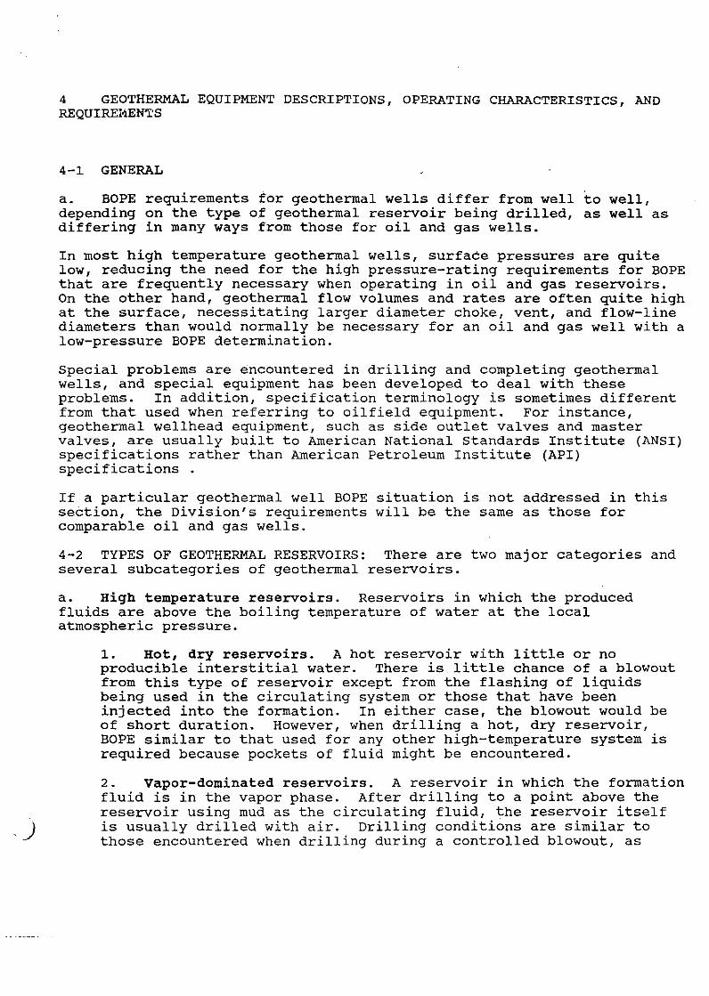
4 GEOTHERMAL EQUIPMENT DESCRIPTIONS, OPERATING CHARACTERISTICS, AND REQUIREI'lEN'l:'S
4-1. GENERAL
a. BOPE requirements for geothermal wells differ from well to well, depending on the type of geothermal reservoir being drilled, as well as differing in many ways from those for oil and gas wells.
In most high temperature geothermal wells, surface pressures are quite low, reducing the need for the high pressure-rating requirements for BOPE that are frequently necessary when operating in oil and gas reservoirs. On the other hand, geothermal flow volumes and rates are often quite high at the surface, necessitating larger diameter choke, vent, and flow-line diameters than would normally be necessary for an oil and gas well with a low-pressure BOPE determination.
Special problems are encountered in drilling and completing geothermal wells, and special equipment has been developed to deal with these problems. In addition, specification terminology is sometimes different from that used when referring to oilfield equipment. For instance, geothermal wellhead equipment, such as side outlet valves and master valves, are usually built to American National standards Institute {ANSI) specifications rather than American Petroleum Institute {API) specifications .
If a particular geothermal well BOPE situation is not addressed in this section, the Division's requirements will be the same as those for comparable oil and gas wells.
4-2 TYPES OF GEOTHERMAL RESERVOIRS: There are two major categories and several subcategories of geothermal reservoirs.
a. High temperature reservoirs. Reservoirs in which the produced fluids are above the boiling temperature of water at the local atmospheric pressure.
1.. Hot, dry reservoirs. A hot reservoir with little or no producible interstitial water. There is little chance of a blowout from this type of reservoir except from the flashing of liquids being used in the circulating system or those that have been injected into the formation. In either case, the blowout would be of short duration. However, when drilling a hot, dry reservoir, BOPE similar to that used for any other high-temperature system is required because pockets of fluid might be encountered.
2. Vapor-dominated reservoirs. A reservoir in which the formation fluid is in the vapor phase. After drilling to a point above the reservoir using mud as the circulating fluid, the reservoir itself is usually drilled with air. Drilling conditions are similar to those encountered when drilling during a controlled blowout, as

)
there is no drilling mud to provide blowout protection or the usual warning signs of a kick. Vapor-dominated reservoirs present conditions that are very different from those encountered in oil and gas reservoirs; subsequently, there are many differences in the drilling methods and BOPE requirements.
3. water-dominated reservoirs. A reservoir in which the formation fluid is in the liquid phase. Because the water entering the well bore from the formation is in the liquid phase at least part of the time, the conditions are very similar to those encountered when drilling through high-pressure saltwater zones in oil and gas fields, and the requirements for BOPE are similar. However, precautions are necessary because the hot reservoir water may flash to steam in the well bore while being circulated out of the well.
b. Low-temperature reservoirs. A reservoir in which the temperature of the produced water is below the boiling point of water at the local atmospheric pressure. Drilling conditions are very similar to those encountered in oil and gas drilling and the requirements for BOPE are identical. The operator is responsible for developing and following safe practices for handling the circulating fluids because they may be very different from those used for oil- and gas-well drilling.
4-3 BOPE DESCRIPTIONS AND REQUIREMENTS
a. High-Temperature Reservoirs
1. General.
a) Elastomer components (e. g. preventer packing elements, ram seals, etc.) must be made of a material formulated specifically to tolerate a steam or hot-water environment.
b) Although it is not a requirement of the Division, some operators prefer to install all-steel rams in place of normal ram assemblies (which are equipped with elastomer seals) in ram-type preventers installed immediately below, or above, the banjo box.
c) Pressure-control equipment must conform to the provisions of Section 3 of this manual.
d) The equipment requirements outlined in this section are mandatory for most wells drilled into high-temperature reservoirs, either vapor-dominated or liquid-dominated, but exceptions may be made on a well-by-well basis, depending on well and geologic conditions.
2. Descriptions of components Unique to Geothermal BOP stacks. (See Figure 24) BOPE stacks used for wells drilled with air in a high-temperature hydrothermal reservoir include some or all of the following devices not commonly used in oil- and gas-well drilling:

,)
a) Slab Gate. An optional, hydraulically operated, singlegate blind ram that is mounted above the permanent wellhead equipment and serves as the lowest element in the BOPE stack. Because a slab gate must be able to function satisfactorily over a wide range of temperatures, the close tolerances and elastomer seal-surfaces found in normal ram-type preventers cannot be used and a complete seal cannot be expected from the slab gate .. This valve is used as a working valve when the drill string is out of the hole. ·
If used, the slab gate is installed above the manually operated, gate-type control valve that is a component of the permanent completion system. The manually operated control valve is capable of a complete seal.
b) Banjo Box. A tee or box with a side outlet that redirects the flow of vapors, liquids, and drilled solids from the well bore to the blooie line. Frequently, the banjo box has a large chamber that will dissipate some energy of the steam or other vapors from the well bore.
c) Blooie Line. A large-diameter line that transfers the flow of well fluids from the banjo box to the muffler and separator when drilling with air. If portions of the hole are being drilled with mud or water as a circulating fluid, the blooie line may be closed off with a blanking plate or gate valve at the outlet from the banjo box, thereby directing the circulating fluid to the flow-line outlet of the rotating head (see f) below). If a gate valve is used, provision shall be made for a secure platform or other means of ensuring the safety of anyone attempting to operate it. (The Division does regulate the selection and arrangement of components of the blooie-line system downstream of the control valve or blanking plate.)
The blooie line should have as few turns in it as practicable, and may have several ports that are used to inject liquids into the air-steam flow. The liquids help in removing drill cuttings removal and in hydrogen-sulfide abatement, if necessary. The choke line may also be vented into the blooie line through one of the ports.
Except for the fact that it operates full-time, the blooie line, together with the muffler and separator (see d) and e) below), perform the same function as the diverter system used in oil- and gas-well drilling.
d) Muffler. A larger-diameter section of the blooie line that reduces the noise of the expelled vapors.
e) Separator. A vertical, cyclone-type device at the end of the blooie-linejmuffler system that separates the cuttings and liquids from the vapors. The vapors escape to the atmosphere from the top of the muffler and the cuttings and liquids are

expelled from the bottom. The separator is similar to the mudgas separator common in oil- and gas-well drilling operations.
f) Rotating Head. A device consisting of an outer housing that is flanged to the uppermost preventer and an inner, bearing-mounted stripper-packer assembly that rotates with the kelly. During normal air-drilling operations, the packer acts as a seal against flowing pressures to keep air, steam, and cuttings away from the rig floor. Normally, the rotating head must be cooled to protect the elastomer seals.
3. Equipment Requirements
a) When Using Air as a Circulating Fluid (Equipment Classification HAl. During the periods when air is used as the circulating fluid in a well being drilled into a hightemperature reservoir, the well must be equipped with the following (minimum) BOPE, listed from top to bottom (see Fig. 24) :
1) A rotating head. 2) A double-ram (pipe and blind) blowout preventer or equivalent equipped with high temperature seals. 3) A banjo-boxjblooie-line system, or approved substitute. 4) A full-closing gate-type control valve installed between the wellhead and the preventerjbanjo box stack. 5) A kill line of 2-inch (minimum) ID with a check valve and at least one gate-, ball-, or plug-type control valve installed as close to the wellhead as is practicable. 6) A blowdown line with a 3-inch (minimum) ID and at least two gate, ball, or plug valves installed as close to the wellhead as is practicable. The line must be anchored securely at all bends and as close to the exhaust outlet as is practicable. As an alternative to an anchored line leading away from the well bore, the blowdown-line may be connected to one of the ports on the blooie line.
At the operator's option, the stack may be equipped with a slab gate and all-steel pipe rams between the required full-closing control valve and the banjo box.
Equivalent systems may be approved by the district engineer.
b) When Using Mud or water as a circulating Fluid. Equipment requirements will vary (as is discussed below) depending upon which casing string is serving as the anchor string for the BOP stack and the type of fluid being used to circulate the cuttings out of the hole. Normally, wells drilled into waterdominated geothermal reservoirs are drilled with drilling mud; however, some may be drilled completely with air, while others are drilled partially with mud and partially with air for certain intervals.

)
=-------
1) Diverter system Requirements for the conductor casing !Equipment Classification HD). A diverter system is not designed to shut in or halt flow, but rather to route the flow to a safe distance away from the rig floor if a blowout occurs before deeper casing is cemented (See Section 2 for selection of equipment). Before drilling out the shoe of the conductgr pipe, the Division will require the following diverter-system equipment unless the operator can demonstrate that such equipment is not . needed.
a. At least one diverter. This diverter may be any one, or combination, of the following devices:
1. A rotating stripper head 2. A remote-controlled, hydraulically operated annular preventer 3. A substitute device approved in advance by the Division.
b. A large-diameter vent line into the wellbore below the diverter required by a., above. A 6-inch or larger ID line is recommended. The vent line may be attached to an outlet on the conductor casing itself or on a spool mounted between the conductor casing and the diverter. This line must be directed away from any nearby public road or normally occupied building.
c. A device in, or design of, the vent line that will prevent flow of well fluids through the line during normal well operations, but will open the vent line to permit flow in an emergency. This requirement may be satisfied by either of the following methods:
1. A riser installed in the diverter line with an outlet above the level of the flow line. This would provide an open-flow diverter system (See Figure 13A).
2. A full-opening control valve, with a throughbore at least equal to the ID of the vent line, mounted in the line near the conductor casing. If a manual valve is used, it must be readily accessible and of an easy-opening design. If a remotely operated valve is used, it is suggested that the system be designed so the valve opens automatically as the diverter is closed. To accomplish this in an installation in which the diverter is an annular preventer, a remotely controlled, hydraulically operated valve may be installed in such a way that the opening chamber of the valve is connected to the
0
closing line of the annular preventer. In such an installation, the valve will be pressured open each time the preventer is closed.
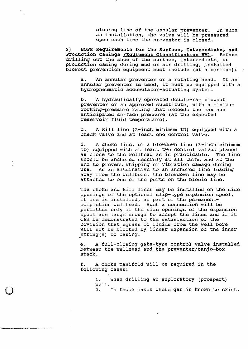
2) BOPE Requirements for the surface, Intermediate, and Production Casings (Equipment Classification HMl. Before drilling out the shoe of the surface, intermediate, or production casing during mud or air drilling, ~nstalled blowout prevention equipment must include (at a minimum):
a. An annular preventer or a rotating head. annular preventer is used, it must be equipped hydropneumatic accumulator-actuating system.
If an with a
b. A hydraulically operated double-ram blowout preventer or an approved substitute, with a minimum working-pressure rating that exceeds the maximum anticipated surface pressure (at the expected reservoir fluid temperature).
c. A kill line (2-inch minimum ID) equipped with a check valve and at least one control valve.
d. A choke line, or a blowdown line (3-inch minimum ID) equipped with at least two control valves placed as close to the wellhead as is practicable. The line should be anchored securely at all turns and at the end to prevent whipping or vibration damage during use. As an alternative to an anchored line leading away from the wellbore, the blowdown line may be attached to one of the ports on the blooie line.
The choke and kill lines may be installed on the side openings of the optional slip-type expansion spool, if one is installed, as part of the permanentcompletion wellhead. Such a connection will be permitted only if the side openings of the expansion spool are large enough to accept the lines and if it can be demonstrated to the satisfaction of the Division that egress of fluids from the well bore will not be blocked by linear expansion of the inner string(s) of casing . • e. A full-closing gate-type control valve installed between the wellhead and the preventerjbanjo-box stack.
f. A choke manifold will be required in the following cases:
1. When drilling an exploratory (prospect) well. 2. In those cases where gas is known to exist.

.. )
3. In those cases where abrasive wellbore fluids might be encountered.
The manifold must be equipped with at least one adjustable choke, a blowdown line (with an ID at least as large as the ID of the choke line), and an accurate pressure gauge. The choke should be of the multiple-orifice type or the cylindrical-gate-andseat type. A remote-controlled choke is preferable to one that is controlled manually.
c) When Using Mud/Water and Air Intermittently as a Circulating Medium (Equipment Classification HMAl. In addition to the BOPE required in subparagraph b) above, the following additional BOPE is required when a well is being drilled with air or another gaseous fluid:
1) A banjo box or approved substitute below the preventers.
2) A blooie-linejmufflerjseparator system.
3) A slab gate andjor ram-type preventer (equipped with all-steel CSO ram assemblies) may be installed between the banjo box and the full-closing control valve required in paragraph 4-Ja3b)2)e above.
d) Heat Exchanger or Mud cooler. When the reservoir is being drilled with mud as the circulating fluid, mud-cooling devices must be used when the temperature of the mud at the flow line is anticipated to be higher than the flash point for a continuous period of more than one hour.
4. Drilling Fluid Requirements. If a well is being drilled intermittently with mud and air, an adequate source of water or drilling mud and weight materials to ensure well control must be readily accessible at the drill site for use at all times when the well is being drilled with air
b. Low-Temperature Reservoirs. Following are the BOPE requirements for low-temperature and temperature-observation wells drilled in high heatflow areas not previously drilled, or areas having a moderate to high potential for blowouts:
1. Equipment Classification LP (see Fig. 25):
a) An annular preventer andjor pipe- and blind-ram preventers.
b) A kill line and a blow-down line installed below the preventer .
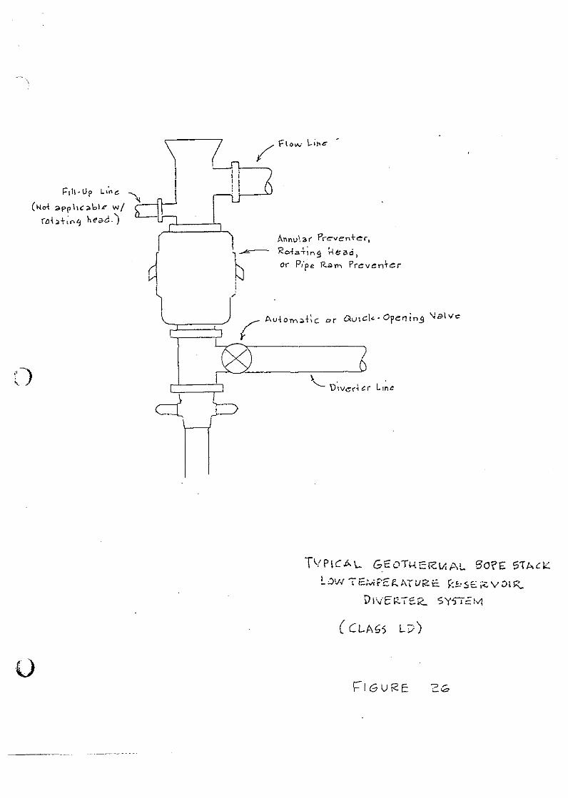
2. Equipment Classification LD (see Fig. 26). In areas where geological conditions are known and where pressures are known to be

;' # ' ' I ..---··· : .. ~) .a1-\r,-:: h c.::~~
,--l.--l.-~r' (t-hy be Annvl<>r Pr.oven-\er"
.("'r CI.>H f-lM)
~ F\ow Line-( 3\:>n :.eo off v:h~:~
-.v:~n 2o-1r.)
l\11 u{(le.-
Ctosinq V;,lw:j
' ... ! - 1 ....... ,..., i <--,.. .... !-jtcct n?e- l<am.;;:,
- ~ Op+ionai
! !
_i
Cbe;;:.k. ~ Ve\ve
~ ~'--'""""LC"'G'-'e-ov---"'~t<.'n..,__e __ r:-:~k ·~:!'"':5'_':'.~::~) .. ::':.'2.::..
dlrl,r ~:?~~-Sp~~-(opt:ar~:)
)
TvPI""' I ' , '- 1-'1-
HIGH
G S CO\ H c\Z\-t,A.\... B OI?E: 5\ ~ C V
IE 1.1 I='E !<:A. tUI< c f< S 5 f "'-VOl (C.

I
_. llovbl e R:;.m Pre , r-----<...J v ern c r
Or ~,hnv\ ar ?reverrtcr
1\'P\C P\ L GEOIHEr<-MAL.. SoPE 5'0-.C,__ Low lt:M'?ERt>.\URE: \<.1.05E-RVo\R
·r Revs." re:tz. Sys!E:M
( CL!>.S5 LP)
f'11!-1Jp L•o.o ........
(Ncl "'PP he ;o\oiF w/ rabt;"~ head.)
()
Annul,a,( P("cven+ec,
Ro.fa-t;ng ~ez.d, 01"' p,·pe R~rn Pr-ev~nt~r
TVPlCA\... GEOT>-iERV.At.. 6o?E S1t.cl:::
L :.>w 1 E: ... ;t=E 1?.. AT iJR: E. ~:-"'SE ;<:. v .:>LIZ
VhiE!-<.ISK.. SYSJ==:tvt
( C::LMS Li/)
f:"IGUi<E:

)
at or below hydrostatic pressure, approval may be given for the use of a single diverter stack with a flow line installed below a blowout preventer, gate valve, rotating head, or approved (equivalent) device.
All required low-temperature BOPE equipment must be fully operational at all times. Pressure-control equipment must conform to provisions in Section 3 of this manual.
4-4 RELATED WELL-CONTROL EQUIPMENT (Auxiliary Equipment). In addition to the requirements listed in Section 4-3 above, the following BOPE must be considered for all wells drilled in known or suspected geothermal resource areas. ·
a. A full-opening safety valve (sized to the working string in use) maintained in the open position on the rig floor at all times while drilling operations are being conducted, and when running casing. While tripping pipe during drilling operations, an operator may choose to make up the valve on the pin end of a joint of drill pipe that is kept readily available for stabbing into the working string. This procedure makes it unnecessary for the rig crew to pick up the valve and attempt to stab it by hand. Also, the hot fluids coming up the working string will be expelled above the crew rather than at the working level.
b. An upper kelly cock installed between the kelly and the swivel. If the uppermost item in the BOP stack is not a rotating head, a lower kelly cock may be used.
c. An internal preventer readily available to the rig crew whenever the well is being drilled with mud or water as a circulating medium.
4-5 BOPE TESTING, INSPECTION, TRAINING, AND MAINTENANCE
a. Testing. The annular and ram-type blowout preventers, the actuating system, and the auxiliary equipment must be tested in accordance with the provisions outlined in Section 5 of this manual; however, pressuretesting of any all-steel ram or gate is not required;
b. Inspection and Actuation. All required BOPE must be inspected and, if applicable, actuated periodically to ensure operational readiness. The minimum frequency of this inspection/actuation is as follows:
1. Once each eight-hour tour, the following are to be performed:
a) Check the accumulator pressure. b) Check the pressure of the emergency backup system. c) Check the hydraulic fluid level in the accumulator unit reservoir. d) Actuate all audible and visual indicators and alarms.
2. Once each trip, but not more often than once every 24 hours, the following are to be actuated:

)
u
a) Pipe rams (before starting out of the hole). b) Blind (CSO) rams (after pulling the pipe from the hole). c) All kelly cocks. d) Drill pipe safety valve. e) Internal Preventer (if required). f) Adjustable chokes (if required). g) Hydraulic control valves (if any).
' 3. Once each seven days, the following are to be actuated:
a) The annular preventer (if installed) on drill pipe or tubing. b) All gate valves in the kill and choke systems. c) The full-closing control valve on the wellhead.
Also, the flange bolts or studs at all preventer and wellhead connections must be tested for tightness every seven days.
c. crew Training. BOPE practice drills and training sessions must be conducted at least once each week for each crew, and may be performed in conjunction with the operational~readiness tests outlined in paragraph 4-5b. Training must be such that each member of the crew has, at a minimum, the following:
1. A clear understanding of the purpose and the method of operation of each preventer and all associated equipment.
2. The ability to recognize the warning signs that accompany a well kick or steam blowout.
3. A clear understanding of each crew member's station and duties in the event of a kick or steam blowout while drilling, tripping pipe, while drill collars are in the preventers, and while out of the hole.
d. Records. A record of all inspections, tests, crew drills, and training sessions must be kept in the daily log book.
e. Maintenance. All equipment must be maintained in accordance with the manufacturer's recommendations andfor the requirements of this manual.

rta/ 0-l/1 '393 ·1 5: 32 . 808-252-5350 R. A. F·ATTERSO!'l & ASSO
,.
R. A. PATTBRSQN & ~PSQQ±ATES 1274 Xika Street Kailua, Hawa1 96734-4521 (808} 262-5651 (808) 262-5350(FAX)
FACSIM::r:r~E COVER SEIEE'r
~~ .. ~:~~ .:. ~·G:· ~ .... ,,.~, ~~ ~~
(~ ~qo
TO: ______ DIVISION OF WATER AND LAND DEVELOPMENT - DLNR ______ ~_
ATTENTION: ___ .JON FLORES·------
FROM: ___ RALPH PATTERSON
SUBJ : ____ SCHflOUU; ___________ _
NO. OF' PAGES INCLUDING COVER SHEET: _____ 2 _____ _
DATE SENT: __ August 4, 199 3 ________ _
Please call if you have a problem with receipt.
JON - PLEASE REVIEW AND DELIVER. WILL MAIL A COPY TOMORROW.

R. A. PAT1 E.RSU~l & A::;~:,O
B. A._ PATTE ...::2.Qlf & A§f:SQC::IA"J..' ii 1274 Kika street · KailuA, Hawai~ 96734-4521
August 4, 1993
Mr. Gordon Akita Department of Land & Natural Resources Division of Water and Land Development P. 0. Box 373 Honolulu, Hl 96809
Dear Mr. Akita;
PAGE. 02
Subsequent to Mr. 'l'agOlDOri 's letter of .July 27th. we have had discussions with OOWALD staff that point toward a different schedule for completing our work on the "Hawaii Geothermal Blowout l'revAntion Manual," and the "Hawaii Geothermal Drilling Guide."
we underst ... nd that a review of the "Blowout Prevention Manual" has indicated that there are :.ome paqes that will need replacing <lulil to typoqraphical errors; when these have been identified, we will reprint the pages and provide them to you. The two bound copies will have replacement pages inserted in the copies.
The draft copy of the "Drill inq Guide" has been submitted for review and comment; since these comments have not yet been received, we wi 11 be unable to deliver the final version on August 6, 1993 , as outlined ln your letter.
We will be glad to expedite the above "orrections and deliveries, but will have to have a reasonable time to make t.he corrections and do the printing and binding when the st:aft reviews are compl .. ted.
'rhe tinal versions of thu documents and diskette files will be delivered, and the presentations to staff and the Geotechnical Advisory committee scheduled as soon as possi.ble.
cc: Mr. Kanabu Tagomorl Mr. Jon Floras

R. A. PATTERSON& ASSOCIATES , 1274 Kika Street Ka1lua, Hawaii 96734-452:
(808) 262-5651 (808) 262-5350 (FAX)
September 20, 1993
Mr. Manabu Tagomori Department of Land & Natural Resources Division of Water and Land Development P. 0. Box 373 Honolulu, HI 96809
Dear Mr. Tagomori;
In accordance with, and in partial fulfillment of, our technical services contract, two bound, and one loose, copies of the HAWAII BLOWOUT PREVENTION MANUAL are forwarded.
A diskette containing the files used to produce this document is also enclosed. The document files are in WordPerfect 5.1 format; there are three WP master documents BOPPREFC.MST, BOPCNTNT.MST, AND BOPREVIS.MST. The cover and appendix division sheets were produced in Harvard Graphics format; copies of these files are also included.
We have made the changes and corrections requested in your letter of September 7, 19 3 3. However, we remain concerned that the DLNRdesired wording describing the optional BOP stack configuration, (Section IV, page 17) would create a hazardous situation in the event of another failure of the wing valves (similar to that which occurred at the KS-1 well in October 1982). If the wing valves are below the ram preventer, an important safety back-up would be missing in the event that the small valves fail or need repair; there would be no l.ast resort to preventing a blowout in this area of the stack.
We are anxious to complete the remaining document reviews and delivery before the end of September. In order to do this, we will have to receive comments on the previously submitted draft of the "DRILLING GUIDE," by Friday, September 24th. If it is not possible to provide these comments by that date, we will have to delay corrections and completion of the Manual until November, due to our other commitments. These include attendance at the annual Geothermal Resources Council meeting, where discussions about Hawaii may include these important publications.
The corrections and deliveries can be expedited, but we will need a reasonable time to make the corrections and do the printing and binding when the staff reviews are completed.
enclosures cc: RCUH (letter only)

Note:
CORRECTIONS. FO~IN.AL ~AW~II BLOWOUT PREVENTION MANUAL
A [c( ~"-'-'"taR c~<IM, W&~ IJIYI.a(2& 4:f. Please see mark-up copy of the Manual for a reference to the requested changes.
Text to be deleted is in [brackets]
Text to be added is underlined
Please make the following corrections:
.....-2.
Page after cover sheet, listing BLNR members and government officials: Misspelled KEPPELER.
Acknowledgement Page, bottom of first paragraph: Misspelled Tagomori.
~3. Preface Page, middle of third paragraph: Delete [and], add an; Misspelled State.
v4. Page 5, second paragraph: Please write as:
~-
Primary features such as lava tubes, irregular layers of ash and rubble contibute to very high horizontal permeability, whereas secondary features such as fractures contibute to very high vertical permeability; both features can pose a problem with loss of drilling fluid circulation and low rock strengths. These features seem to diminish downward, but appear to extend to depths of about 2000 feet.
Page 10, third paragraph, line 6: Delete [Commonly] from the beginning of the sentence; add commonly to line 7.
Example: The deliberate actions to optomize safety in geothermal drilling commonly will be specified or reflected in four distinct sections of the drilling plan, as follows:
~- Page 15, second paragraph, line 5: add while the drill string is.
Example: situations such as active drilling and tripping, or while the drill string is out of the hole.
~- Page 17, last line: Delete [Another possible arrangement might omit (continued on page 18) the ram preventer shown below the choke and fill line valves, saving the height of this valve. This would remove an important safety back-up in the event that the small valves fail or need repair; without this ram preventer there would be no last resort to preventing a
1
.. ,.

blowout in this area of the stack.]; add:
Another possible arrangement is to remove the lowermost pipe ram shown in Figure 2 and install it above the choke and kill lines, in tandem with the blind ram. A full BOP stack should be maintained at all times while drilling in the vicinity of the production zone.
~. Page 24, bottom paragraph, line 6: add way.
...A.
t-Jo 10.
Example: The imformation provided by way of monitoring procedures, with careful integration and evaluation, can make iportant contributions to an Operator's prevention strategy .
Page 27, last paragrpah, line 11: delete space to the left of the word "where" .
Page 29, first paragraph, line 2: delete spaces after ''events'', ''on'', ''other'', and before and after ''A''.
·,/1:'1. Page 32, bottom of page: underline Driller and Logger and format as follows:
Driller drilling penetration rate drilling fluid circulation
Logger temperature variations secondary mineralization formation fluid entries
~2. Page 45, last paragraph, line 7: Delete space in middle of paragraph.
03. Appendix A-1, Manual Review and Revision: delete the last paragraph.
~4. Appendix C-1, References:
va:s.
References 3 and 10: change superscripted 2 in H2 S to subscript. Example: H2 S
Reference 12: delete [Geothermal] at the end of the first line; add Geothermal at the beginning of the reference.
Example: Geothermal Regulations and Rules of Practice &
Procedure, State of Nevada.
Appendix C-2, line 2 "Sumida,Gerald, A.": delete
2
of reference [and] ; add an.
beginning with

Example: Sumida, Gerald A., Alternative Approaches to the Legal, Institutional and Financial Aspects of Developing an Inter-Island Electrical Transmission Cable System.
~- Appendix D-2, Glossary:
v First paragraph: add a period (.) after "surface".
Definition of casing: add or injection; delete [from the well] :
vExample: casing n. steel pipe, cemented in the wellbore to protect it against external fluids and rock conditions, and to facilitate the reliable and safe production or injection of geothermal fluids.
~lete second definition of casing.
~ Appendix D-5, Definition of pipe ram: delete [and]; add ££ill and ram.
Example: See ram and ram blowout preventer.
3

HAWAII GEOTHERMAL BLOWOUT PREVENTION MANUAL
State of Hawaii DEPARTMENT OF LAND AND NATURAL RESOURCES
Division of Water and Land Development

JOHN WAIHEE Governor
BOARD OF LAND AND NATURAL RESOURCES
KEITH W. AHUE, Chairperson
SHARON R. HIHENO, Member at Large
MICHAEL H. HEKOBA, Oahu Member
HERBERT K. APAKA, .JR., Kauai Member
WILLIAM KENNISON, Maui Member
CHRISTOPHER J. YUEH, Hawaii Member
DEPARTMENT OF LAND AHD NATURAL RESOQRCES
KEITH w. AHUE, Chairperson
JOHN P. KEPPELER II, Deputy
DOHA L. HAHAIKE, Deputy
DiviSION OF WATER AND LAMP DEVELQPMEMT
MAHABU TAGOMORI, P. E., Manager- Chief Engineer

ACKNOWLEDGEMENT
This document was prepared by R. A. Patterson & Associates, Kailua, Hawaii, for the Hawaii Department of Land and Natural Resources under Contract Agreement No. RCUH P. o. 4361021. The work was performed by Ralph A. Patterson, William L. D'Olier, and Herbert E. Wheeler. We wish to gratefully acknowledge the assistance of the staff of the Division of water and Land Developaent, under the direction of Manabu Tagomori, and of the invaluable suggestions and assistance of all those who discussed the project with us.
Development of this Manual would not have been possible without the willing cooperation of many managers, technicians and professionals in the geothermal industry, various laboratories and academic institutions, and in other areas where their knowledge was helpful in presenting the review and recommendations of the Manual. The authors wish to acknowledge their help and candor, and their accumulated knowledge that has made our job easier.

PREFACE
The prevention of an uncontrolled well flow, commonly known as
a "blowout", is of vi tal importance for geothermal operators, drilling
crews, state and county regulators, and the general public. Geothermal
well blowouts have not been the cause of a significant number of
fatalities, and the danger of fire, as in petroleum drilling, is quite
low. However, blowout incidents may have a negative impact on surface
and subsurface environments, cause resource waste, and develop
unfavorable public perceptions of geothermal activity. These concerns
are powerful incentives to operators and regulators to minimize the
risks of a blowout.
This Manual has been developed to promote safety and good
resource management by discussing and describing blowout prevention
as it can best be practiced in Hawaii.
The intent of this Manual is to provide the necessary information
to guide regulators and operators in the practices and procedures,
appropriate to each drilling situation, that will minimize the risks
of a blowout. The Manual is also intended to promote an informed
flexibility in blowout prevention practices, and to supplement State
and County regulations, especially those pertaining directly to
drilling permits and operations.'
This first edition of the Blowout Prevention Manual is a likely
candidate for revision as more drilling experience and information is
gathered in the exploration and development of Hawaii's geothermal
resources.
1 Department of Land and Natural resources (DLNR) Title 13, Subtitle 7. Water and Land Development; Chapter 183.

CONTENTS
Acknowledgement
Preface
YL.
YI.L.
VIII.
l..lL..
x.._
XL.
SCOPE
GEOTHERMAL DRILLING RISKS IN ijAWAII
GEOTHERMAL WELL PLANNING
BLOwoUT PREVENTION STACKS AND EQUIPMENT
EQUIPMENT TESTING AND INSPECTION
DRILLING MQNITORING PROCEDURES
KICK CONTROL
BLOWOUT CLASSIFICATION
SUPERYISION ANQ TBAINING
POST COMPLETION BLOWOUT PREVENTION
BLOWOUT PREVENTION IN SLIM HOLES
APPENDICES
A - Procedures for Manual Review and Revisions
B - Illustrations
c - References
D - Glossary
i
Page
l
2
6
13
20
22
34
37
39
42
43
I. SCOPE
The material in this Manual has been extracted from many key
information sources in order to present a complete and accurate review
of the practices of geothermal well control in Hawaii. In developing
this Manual, a careful review of drilling to date in the Kilauea East
Rift Zone (KERZ) was conducted. The KERZ is where nearly all Hawaii
geothermal drilling has taken place, and is where most experts believe
the geothermal resources will be developed.
The general belief in the industry is that each area is "unique",
since each prospective geothermal area throughout the world has proven
to have its own characteristics in terms of drilling conditions,
resource chemistry, geology, etc. While this may be true in detail,
some similarities do exist among geothermal areas located in, or
nearby, active volcanic areas. Thus, it has been helpful to briefly
review well control techniques and experiences from other similar
volcanic areas around the world. some of the information gathered may
have an influence on geothermal drilling in Hawaii.
In order to review the experiences in Hawaii and in other
geothermal areas where active vulcanism is prevalent, a great number
of specific publications and selected references were consulted. Many
of these are listed in Appendix c, References. In addition, much of
the information and many recommendations contained in this Manual came
from the accumulated experience of others who were consulted on
various elements of the items presented. A partial list of those
consulted is also contained in Appendix c.
This Manual defines a blowout prevention strategy for geothermal
drilling in the State of Hawaii. The essential co•ponents of this
strategy
1)
2)
are:
!~roved risk analysis and well planning.
SOund selection of blowout prevention stacks and associated
equipaent.
J) Rigorous use of drilling monitoring procedures.
4) Expertise in kick control and blowout prevention equipment
utilization.
5) Excellence in supervision and training of drilling
personnel.
1

II GE,\1THERMAL DRILLING RISKS 1.1 HAWAII
THE VOLCANIC DOMAIN
The State of Hawaii consists of a chain of volcanic islands.
Each island is a composite of several volcanic eruptive centers built
up by a succession of basaltic lava flows, first as submarine deposits
and subsequently as volcanic lands (or subaerial deposits.) These
basaltic lava flows form a sequence of near horizontal layers
consisting of hard crystalline flow rocks interbedded with lesser
amounts of highly variable rock debris. These flow sequences are
evident in extensive outcrops and in lithology logs from water well
drilling.
Recently recognized geothermal resources in Hawaii are
characterized by relatively small prospective areas which are strongly
associated with active or recent volcanism. The highest probability
areas for geothermal development overlie the volcanic rift zones which
are, or recently were, deep conduits for magma transport away from the
volcanic eruptive center. Hawaiian geothermal drilling to date has
been confined to the active Kilauea East Rift Zone (KERZ). In the
KERZ, the magma and lava processes (1900°F and higher) provide very
high subsurface temperatures. Large amounts of meteoric water
(groundwater) and seawater intrude into the KERZ geothermal resource
zones, providing an abundant fluid supply for heat transfer.
Geothermal drilling in Hawaiian rift zones involves distinctive
risks. A reasonable initial identification of hazards and risks is now
possible due to KERZ drilling experience, combined with extensive
studies by the Hawaii Volcano Observatory (HVO) of KERZ rift zone
function, structure and dynamic processes.
knowledge can be used to refine geothermal
This experience and
drilling programs and
procedures to minimize the risks of upsets and blowouts.
KERZ DRILLING TO DATE
The most valuable subsurface information for this Blowout
2

Prevention Manua... comes from 12 deep geot •• armal wells and three
exploratory slimholes drilled in the KERZ since 1975. Rotary drilling
rigs appropriate to the drilling objectives were used on the twelve
geothermal wells. Common drilling fluids used in this rotary drilling
are mud, water, aerated fluids and air. The well depths range between
1,670 and 12,500 feet below the ground surface. Operators for the
well drilling included four private resource companies and one public
sector research unit.
As of mid 1992, nine wells had penetrated prospective high
temperature rocks and seven of these were flow tested or manifested
high temperature fluids. The resource discovery well, HGP-A, completed
in mid-1976, provided steam to a 3MW demonstration electrical
generation plant between 1981 and 1990. Two of the nine wells incurred
casing contained blowouts in 1991 upon unexpectedly encountering high
pressured geothermal fluids at shallow depths.
Three deep scientific observation holes (SOH) were drilled for
resource evaluation as continuously cored exploratory slimholes to
5,500-6,800 foot depths in 1990 and 1991. These SOHs helped to prove
that favorable high temperatures prevail over a ten mile interval
along the KERZ. These holes did not encounter subsurface conditions
that involved significant blowout risks; however, special blowout
prevention equipment must be considered for future use of the slimhole
technology in Hawaii.
SUBSURFACE CONDITIONS IN PROSPECTIVE AREAS
High temperatures, commonly in the 600-700"F range, are
characteristic of production zones in the volcanically active rift
zones. The prospective geothermal reservoir occurs in the roof rock
above .the deeper magma conduits. The well completion targets are loci
of permeable, highly conductive fault and fracture zones which are
secondary mineralization. Magma generally enclosed by extensive
transport downrift and its planar injection upward into the roof rock
are the primary heat sources for the geothermal resource.
3

The pr~mary hazard of geothenual drilling in the
volcanically active KERZ is the currently unpredictable distribution
of fault planes and major fractures. The walls of these geologic
structures are commonly sealed by secondary mineralization; thus
creating conduits for geothermal fluids. These fault and fracture
conduits, can present pressures in the range of 500 to 750 psi above
normal hydrostatic pressure, particularly as they extend upward into
cooler ground water regions. Unexpected entry into such over
pressured fault planes and fractures can cause substantial upsets to
all well control procedures.
Primary features such as lava tubes, irregular layers of ash,
and rubble contribute to very high horizontal permeability, whereas
secondary features such as fractures contribute to very high vertical
permeability; both features can pose a problem with loss of drilling
fluid circulation and low rock strengths. These features seem to
diminish downward, but appear to extend to depths of about 2000 feet.
An important feature of the KERZ is the seaward slip-faulting of
its southeastern flank caused by cross rift extensional stress. This
seaward sliding of the roof rock, coupled with seismicity, results in
mol ten dike intrusions and fracturing. Dike intrusions allow an
abundant supply of heating and create prospective fracturing for the
geothermal reservoir. All these features further contribute to low
rock strengths in shallow, near surface volcanics, which can be a
problem when attempting to locate a sound anchor for wellhead blowout
prevention equipment.
The geohydrology of the KERZ involves large volumes of
groundwater and seawater. The relatively cool groundwater body,
located just above sea level, is maintained by high annual rainfall
and a high rate of infiltration. The KERZ geothermal fluid system also
may be fed by a major groundwater basin on Mauna Loa's eastern flank.
Large volumes of seawater have the potential to penetrate the
geothermal reservoir through fractures at depth. Earthquakes in the
region may cause existing fractures to widen or may create new
fractures. An increase in the salinity of the fluids produced by the
4
HGP-A well may hav~ been caused by earthquake ~nduced fractures. High
hydrostatic pressures prevail in active rift zones, but these can be
escalated to higher fluid pressures in the temperature conditions
prevailing. The fresh and saline groundwater body, shown to exist as
deep as 2,500 feet in the Puna geothermal field, may prove to be a
common condition, but not one that can be expected at every proposed
well location.
SUMMARY
The KERZ geothermal drilling experiences prove two significant
hazards that must be addressed in a blowout prevention strategy for
every proposed well:
l. Significant fault and fracture planes can be sealed conduits
for overpressured geothermal fluids. These features might
eventually prove to be predictable or detectable by drilling
precursors. Blowout prevention planning, equipments and
procedures must be taken as a critical requirement, ready
for immediate and proficient use.
2. Weak and broken near surface volcanic rocks. The recognition
of this condition is a precursor to obtaining a reliable
casing anchor, which is fundamental to safe blowout
prevention by complete shut off (CSO) of the well.
5

Iii. GEOTHERMALWELL PLA&JCliNG
INTRODUCTION
The proven higher costs and uncertainties of Hawaiian geothermal
drilling operations are sound reasons to make an extraordinary
investment in well planning. Detailed planning is a must for each and
every type of well because of the paucity of subsurface information
and the small base of drilling experience to date. Blowout prevention
is an integral element of geothermal well planning.
WELL PLANNING OBJECTIVES
Safety The concept of safety must be carefully applied for all
workers and activities at the wellsite and for the public. A blowout
prevention strategy is a crucial part of any successful practice of
safety in geothermal drilling; it is a necessity in Hawaii.
Well Function Geothermal wells, if beneficial development is to
be attained, must convey and control very large quantities of fluid
and energy, hopefully for the greater part of the 30-year life that
is expected in electric power systems. The HGP-A discovery well
demonstrated a reasonable performance in the production mode from
1983 to 1990.
Reasonable Cost Hawaiian geothermal wells are in the very costly
category; perhaps $2,500,000 per well is a representative minimal cost
( 1992$) if no significant problems impact a good drilling plan.
Competent planning might cost only 1 or 2% of the total cost of a
successful well.
H1gh quality well planning will assure a greater degree of
safety and improved well functions. Proper well planning will allow
the Operator to be more confident in responding to the upset
conditions that can't be avoided and actual drilling performance can
be better assessed for continued improvements in future Hawaiian
~/fiUJ/IICW..,_ 11, 1993 6

geothermal wells.
DRILLING TARGETS AND WELL TYPES
Geothermal drilling targets in the volcanic realm of Hawaii can
be organized into three simple classifications:
Exploration targets - to discover the resource, are generally
identified by a favorable combination of subsurface data
indicating heat, fluids and fractures (voids). Targets that can
win drilling funds, but which present a high risk exposure, are
usually classified as exploratory by the Operator and
participants.
Reservoir targets - to develop the resource, are generally
qualified by high temperatures, _indicated fault planes and
fracture systems, or by nearby well production data. The
probability of penetrating both high temperatures and fluid
producing permeability intervals is high. Hawaiian geothermal
reservoirs are of the hydrothermal type (the predominate type now
in worldwide utilization.)
SuppleiiE!Iltal targets - to conduct research on the resource , are
comprised of scientific and/or observational objectives which can
contribute to a better understanding of a geothermal resource and
its enclosing subsurface environment.
At the present level of knowledge in Hawaiian rift zones, no
class of geothermal drilling target can be confidently identified to
have lower blowout risks. Off rift geothermal drilling targets may
offer the perception of lower drilling risks, however, no such
drilling has been undertaken as of 1992.
Geothermal wells can be categorized as to function and several
additional features. The common types of wells include the following:
Exploration well. Any well drilled to evaluate a prospective
~/WU)~ 1~. 1112 7

geothermal resource target, usually at svme significant distance
from an established or proven geothermal reservoir. Hard and
proximal subsurface data are not likely to be available for a
blowout prevention plan; diligent drilling monitoring procedures
(see Section VI) and casing plan flexibility are essential to
blowout risk reduction in exploration wells.
Production well. Any well designed to exploit the energy and
fluids of a geothermal reservoir for beneficial use or
demonstration purpose.
wells can be better
subsurface conditions.
Blowout prevention plans for production
specified to more confidently known
Injection well. Any well designed to return geothermal effluent
to the reservoir or other deep disposal zones. Injection wells
will have blowout prevention requirements similar to nearby
production wells.
Slimhole. This type of geothermal well is identified by its
small diameter borehole, 6 to 4 inches, compared to the 17~ -
8~ inch hole diameter range commonly used worldwide in the
geothermal industry. The slimhole technology, presently surging
in evaluation and use in the petroleum industry, has a distinct
blowout risk and prevention requirement. The technology has been
safely introduced in the KERZ when HNEI accomplished three
continuous boreholes between 5500 and 6000 foot total depths in
its Scientific Observation Hole Program (1989-91). Discussion
of the blowout prevention in slimholes is presented in Section
XII.
Deep versus shallow wells. These are terms of convenience in
ioheir general usage; however, regulations may impose a legal
definition on them. A historical point of interest in the KERZ
should be noted; several early geothermal exploration holes,
drilled safely with cable tools, encountered near boiling waters
at very shallow depths next to recent lava flow fissures and
vents. Depth seems to have no correlation with blowout risk in
aot'PL&IDil:aO/IU.D~ 11, lg92 8

Hawaii's geL..:'hermal drilling to date. However, it should be
evident that relatively shallow blowouts in the porous surface
lava rocks and large fissures, broadly prevailing in Hawaii,
could be particularly difficult to kill.
Vertical versus deviated wells. It appears that Hawaiian
geothermal wellfields will be extensively developed with deviated
wellbores. Blowout prevention requirements are not altered in
any type of geothermal well by the vertical or deviated course
of its wellbore.
THE DRILLING PLAN
Every geothermal well proposed for funding and permitting will
require a drilling plan. Regardless of the geothermal well type, the
drilling plan is the specific technical document that should reflect
the best thinking on how the well can be safely constructed and its
function obtained at reasonable cost. Safety is considered on a broad
front in a carefully prepared drilling plan. The deliberate actions
to optimize safety in geothermal drilling commonly will be specified
or reflected in four distinct sections of the drilling plan, as
follows:
1. Casing and cement. The intended function of the proposed
well will be a factor in casing design and cementing
procedures selected. However, the best available subsurface
data sets on geology, hydrology, pressure and temperature
profiles, formation failure thresholds (fracture gradient),
together with the wellsi te elevation, comprise the basis for
increased safety in drilling and quality of construction.
The subsurface conditions and wellsite elevation are unique
to each intended wellbore; the proposed casing and cement
plan must reflect a reasonable response to these conditions.
KERZ drilling experience reveals several special casing
concerns for blowout prevention.
a. A preference to cement the surface casing
9

(Lummonly 20 inch diameter) b~Low the water table can
be acknowledged. Where the groundwater table is within
600-800 feet below the surface, an approximate 1,000
foot length of surface casing would meet this
objective. Where the groundwater table is much deeper,
it could be difficult to obtain a good cement sheath
on surface casing set at, say 1,700 feet, because of
the presence of lost circulation zones and incompetent
rock in which to cement the casing shoe. Prudence
suggests that it is better to obtain a quality cement
sheath on a shorter length of surface casing.
b. Independent of the quality of cement sheath
obtained on surface casing, the possibilities of
fractures, other permeable paths to the surface, and
low formation fracture gradients exist in the near
surface volcanic rocks penetrated by the surface
casing. This points to a serious risk in using a
co•plete shut off (CSO) blowout prevention system on
the surface casing while drilling to the intermediate
casing depth. A CSO could force unexpected hot and
possibly pressured formation fluids to an external
blowout (outside the surface casing and cellar).
External venting of this type can pose more complex and
precarious kill operations, and also threaten the
drilling rig's ground support. Accordingly, a
diverting capacity and large diameter flow line from
the wellhead to a distant disposal point is to be
considered. This approach would contain such an
uncontrolled flow inside the surface casing and afford
a safer kill procedure confined to the wellbore.
c. Intermediate casing (commonly 13-3/8 inch diameter)
may be set at depths between 1, 000-2, 500 feet below the
surface casing shoe if no unexpected geothermal fluids
or anomalies are encountered. The intermediate casing
10

stiue depth should optimallz be below the major
groundwater body. It should also be below extensive
fracturing that may reach up to the groundwater table,
frequent occurrence of lost circulation zones, and less
competent volcanic rock. Because the intermediate
casing becomes the anchor casing for the complete BOP
equipment stack required to drill to total depth, it
is critical that the cement sheath in the open hole
(17~ inch diameter) annulus be of the highest possible
quality. The findings in the 17~ inch drilled hole
should be carefully studied. Any adverse downhole
conditions can be mitigated by cementing the bottom
portion of the intermediate casing as a liner in the
open hole interval (lapped several hundred feet into
the bottom of the surface casing). The upper portion
can be run and cemented as a tie back string inside
the surface casing. Each of the two cement jobs
required should be of enhanced quality, should offset
the external natural hazards and should optimize the
anchor for the complete BOP equipment stack with its
multiple CSO capacity over a full range of drilling
fluids.
2. Drilling fluids. The subsurface conditions encountered
within the KERZ are prompting the use of many drilling
fluids ranging from moderate to low density muds, water,
aerated muds and water, to foam, and air. Additionally, the
ability to switch drilling fluids promptly is being
recognized as a cost effective advantage in greater well
control. This practice demands the use of BOP equipment
compatible with a broad range of drilling fluid options in
a single wellbore. The diversity and flexibility of
drilling fluid utilization in Hawaii is encouraging, not
only because all fluids can be controlled by available BOP
equipment, but because this approach should lead directly
to advanced safety margins, reduced drilling times and lower
&OPPLUIIlJIG/IfLD~ 11, 199:2 11

costs. Drilling fluids and geott.~rmal well control are
further discussed in Section VI.
3. Drilling M9nitoring. This activity
integrated in thorough drilling plans at many
is, however, quite important and deserves more
as an effective method to reduce blowout risks.
is usually
points. It
recognition
A detailed
consideration of drilling monitoring procedures is presented
in Section VI.
4. Blowout Prevention. Drilling plans may contain minimal
specific discussion of blowout prevention; a graphic sketch
of the proposed BOP equipment stack may be the lone obvious
recognition of the subject. However, a competent drilling
plan will reflect, in its detailed provisions, an Operator's
blowout prevention strategy •. The implementation of risk
reduction will be evident in the casing, cementing and
drilling fluid provisions, in the drilling monitoring
procedures, in proper training, and finally in the BOP stack
and its supplemental equipment. The drilling plan should
reveal the Operator's awareness that a blowout~ happen,
and reflect the drilling supervisor's responsible
determination that it has been given the least possible
chance to occur in the proposed well. Blowout prevention is
every Operator's final responsibility; it is achieved first
in the thinking and actions of all drillsite personnel
through training, by the practice of sound procedures, and
by the use of reliable, proper equipment.
BOPPLUIDIG/11l.D~ 11, l99l 12

IY. BLOWOUT PREVENTION STACKS
AND EQUIPMENT
INTRODUCTION
Hawaii's geothermal drilling industry, still in a formative
stage, has gained sufficient experience and information to provide
reasonable guidance to the identification of more reliable and safer
blowout prevention stacks and equipment. The blowout prevention stack
on the wellhead, when all other well control procedures have failed,
must function reliably to obtain a complete closure or effective
control of unexpected fluid flows from the wellbore. Blowout
prevention stacks and related equipment are not simple systems; they
rely on integrated mechanical, hydraulic and electrical processes to
operate. Both redundancy and sophistication exist; however, the risks
of human error in critical situations have not been eliminated.
Blowout prevention systems require careful selection, maintenance, and
repetitive training of drilling crews to attain the reliability and
safety which are essential in the final defense against an actual
blowout.
BOP DEFINITIONS AHD FUNCTIONS
1. Definitions
The term blowout preyention equipment CBOPl here means the
entire array of equipment installed at the well to control kicks and
prevent blowouts. It includes the BOP stack, its activating system,
kill and choke lines and manifolds, kelly cocks, safety valves and all
auxiliary equipment and monitoring devices. (see Glossary in Appendix
D for these terms).
The BQP stack. as
preventers, spools, valves,
wellhead while drilling.
used here, is that combination of
and other equipment attached to the
A diverter staclt is a BOP stack that includes an annular
13

preventer, with a ~ent line beneath. A valve ~J installed in the vent
line so that the valve is open whenever the annular preventer is
closed, thus avoiding a complete shut off (CSO), and diverting the
flow of fluids away from the rig and personnel.
A full BQP stack is an array of preventers, spools, valves,
and other equipment attached to the wellhead such that complete shut
off (CSO) is possible under all conditions.
2 • Functions
The main function of the BOP equipment is to safely control the
flow of fluids at the surface, either by diversion or by complete shut
off. The equipment must be adequate to handle a range of fluid types,
pressures, and temperatures, and to accommodate different drilling
situations such as active drilling and tripping, or while the drill
string is out of the hole. The requirements of the BOP stack are to:
a. Close the top of the wellbore to prevent the release of
fluids, or, to safely divert the fluids away from the rig and
personnel.
b. Allow safe, controlled release of shut in, pressured fluids
through the choke lines and manifold.
c. Allow pumping of fluids (usually mud or water) into the
wellbore through kill lines.
d. Allow vertical movement of the drill pipe without release of
fluids.
Selection of BOP stacks and equipment should be made jointly by
an experienced geothermal drilling engineer and drilling supervisor.
It is preferable to employ a supervisor that is experienced in Hawaii
geothermal drilling experiences and conditions.
THE BOP AHCHOR
Complete shut off capability with a BOP stack requires the
existence of a BOP anchor. Three key factors are required for a sound
BOP anchor:
BOPI'UoCSIUQDD/BD'/WU)f11U'c.b 30, 199J 14

1. A mechanically sound, continuous stee~ casing of reasonable length, which probably will be 1000 feet or more, attached to the BOP stack.
2. A continuous and solid cement sheath in the annulus between the casing and the rock wall of the wellbore.
3. An impermeable rock interval around the wellbore and cement
sheath. The entire section of rock need not be impermeable but priority is given to placing and cementing the casing shoe in a
thick interval of competent and impermeable rock.
IMPACTS OF SUBSURFACE RISKS
Hawaii geothermal drilling has inherent risks due to the
unpredictability of subsurface conditions. Recognizing the risks and
being prepared for all possible conditions is the best form of blowout
prevention. Subsurface conditions that may pose the risk of a well
blowout are listed below:
1. The almost certain inability to obtain a sound BOP anchor with
surface casing in the weak, often broken, and vertically permeable
near surface volcanic rocks. As discussed in Section II, if a "kick"
occurs, these shallow rocks will not allow a cso at the wellhead without posing a significant risk of creating an externally vented
well casing blowout. (For discussion of externally vented blowouts, see Section VIII.)
2. The unexpected entry, while drilling, into a major fault and
fracture conduit which is charged with overpressured geothermal fluid&. Termination and control of such events requires the certainty
of a wellhead CSO with a full capacity BOP stack. 1
1 In the KERZ, sudden geothermal fluid flows, which subsequently registered 500 to 700 psi shut-in wellhead pressures, were encountered at depths shallower than expected~ in one case as shallow as 1,400 feet.
BOH'f'AaiiiiQUIJ'/BD',IIILD/Mrcb 30, 1193 15
The risk factors cited above reveal the importance of knowing
when a BOP anchor and consequent cso capacity are available to prevent
a blowout. If they are not available, diversion of uncontrolled flows
is judged to be the more prudent response. On these fundamental
considerations, two basic BOP stacks are recommended for Hawaii
geothermal wells which are drilled with rotary rigs for exploration,
production or injection purposes.
BOP STACK RECOMMENDATIONS
1. Diyerter Stack (Figure 1-Appendix Bl
A diverter consisting of an annular preventer and a vent line
should be installed on the surface casing. In Hawaii, this casing
is typically 20 inches in diameter and is cemented in the 800 -
1,100 foot depth range. Incompetent near surface volcanic rock
and the high risk of cementing failure will not provide an
adequate BOP anchor for the surface casing. CSO is not intended
with this equipment; diversion of fluids is deliberate to avoid
creating externally vented blowouts, and for personnel and rig
safety.
2. Full BOP Stack (figure 2-Appendix B
A full BOP stack should be installed on the intermediate casing.
In Hawaii, this casing is typically 13-3/8 inches in diameter,
and is cemented in the 2, 000 - 3, 500 foot depth range. This
deeper casing, cement sheath, and host rock serves as a BOP
anchor. The selection and arrangement of this stack allows for
the use of a full range of drilling fluids (mud, water, aerated
~luid, foam, air) and should be a geothermal industry premium
stack that is capable of confident, immediate CSO over the range
of temperatures and pressures anticipated. If a sufficient BOP
anchor is not obtained, this stack also has diverter capacity
because of the flow "T"jvent line, or banjo box/blooie line,
included in the stack.
16

The BOP stack arrangement shown in Figure 2 is one of several
combinations available. Another possible arrangement is to remove
the lowermost pipe ram shown in Figure 2 and install it above the
choke and kill lines, in tandem with the blind ram. A full BOP
stack should be maintained at all times while drilling in the
vicinity of the production zone.
ADDITIONAL RECOMMENDATIONS
1. Diyerter stack. The di verter stack should have the
following characteristics:
a. A minimum pressure rating of 2,000 psi for all
components.
b. Minimum vent line diameter of 12 inches.
c. A full opening valve on the vent line that opens
automatically when the annular preventer is
closed; QR a 150 psi rupture disk and a normally
open valve.
d. The vent line directed through a muffler.
e. H,S abatement capability connected to the vent
line.
2. Full BOP Stack. The Full BOP stack should have the
following characteristics:
a. A minimum pressure rating of 3,000 psi for all
components. A pressure rating of 5, ooo psi is
recommended when indicated by the risk analysis
of the well. For teaperature impacts on pressure
ratings, see Figure 3 Appendix B.
b. Lower spool outlets - 2 inch diameter for a kill
line and 4 inches for a choke line.
c.
d.
BCII'ftiC:U&~P/811'/WUJ/IIUCb lO, 1993
The pressure ratings for the kill and choke lines
the same as the stack.
All preventers should have high temperature rated
17

ram rubbers and packing ~-d ts.
BOP EQUIPMENT RECOMMENDATIONS
1. Kill Line. 2 inch diameter kill line from pumps to
spool, Two full opening valves and one check valve at the
spool. Fittings for an auxiliary pump connection; pressure
rating for the kill line the same as the stack. The kill
line is not to be used as a fill up line.
2. Choke Line and Choke Manifold. 4 inch choke line and
manifold; pressure rating the same as the stack. Two full
opening gate valves next to the spool; one of these valves
remotely operated.
3. Actuating system. The actuating system should have an
accumulator that can perform all of the following after its
power is shut off:
a. Close and open one ram preventer.
b. Close the annular preventer on the smallest drill
pipe used.
c. Open a hydraulic valve on the choke line, if used.
The actuating system is to be located at least 50 feet from
the well, with two control stations - one at the drillers
station on the rig and one at the actuating system location.
Valves shown may be hydraulically or manually operated, as
appropriate for the intended service. However, valves should
be operable from a remote hydraulic control, or by
mechanical extensions, if they are located where they are
not readily accessible during a well control incident.
4 I Other equipment I During drilling the following
miscellaneous BOP equipment is to be provided:
a I Upper and lower kelly cocks and a standpipe valve.
b. A full opening safety valve, to fit any pipe in
80PftACU6-.uiP,IDII/IILD,IIIareb JO, 1993 18

the hole. Kept on the ri~ floor.
c. An internal preventer, kept on the rig floor, with
fittings to adapt it to the safety valve.
d. Accurate pressure gauges on the stand pipe, choke
manifold, and other suitable places that may see
wellbore pressure.
e. All flow lines and valves rated for high
temperature service.
&OPII'l'KDIIQUIP ,IJIBif/lfUI/JI&rcb 30, 1993 19

V. E'V'UIPMENT TESTING AND IN$fECTION
In general, a visual inspection and an initial pressure test
should be made on all BOP equipment when it is installed, before
drilling out any casing plugs. The BOP stack (preventers and spools,
choke and kill lines, all valves and kelly cocks) should be tested in
the direction of blowout flow. In addition to the initial pressure and
operational test at time of installation, periodic operating tests
should be made.
Pressure tests should subject the BOP stack to a minimum of 125%
of the maximum predicted surface pressure. If the casing is tested
at the same time then the test should not be more than 80% of minimum
internal yield of the casing at the shoe. If a test plug is used, the
full working pressure of the BOP stack can be tested; a casing test
would be made separately. Testing of the actuating system should
include tests to determine that:
1) The accumulator is fully charged to its rated working
pressure;
2) The level of fluid is at the prescribed level for that
particular unit;
3) Every valve is in good operating condition;
4) The unit itself is located properly with respect to the
well;
5) The capacity of the accumulator is adequate to perform all
necessary functions including any kick control functions
such as hydraulic valves that are using the same unit for
energy;
6) The accumulator pumps function properly;
7) The power supply to the accumulator pump motor will not be
interrupted during normal operations;
8) There is an adequate independent backup system that is ready
to operate properly; and
SC&ZUIIW\Ba\~ 11, 1912 20

9) The con~rol manifold is at least s~ feet from the well and
a remote panel is located at the driller's station.
10) All control valves are operating easily and properly, have
unobstructed access and easily identifiable controls.
The sequence of events to test the BOP stack and all other valves
depends on the stack configuration, but it is important that all
equipment is tested, including the annular preventer, pipe rams, cso
rams, upper and lower kelly cocks, safety valves, internal preventers,
standpipe valve, kill line, choke manifold and choke control valve,
pressure gauges, and any other items that are installed as part of the
BOP equipment.
In addition to the testing of BOP equipment when it is first
installed, there should be frequent BOP testing and drills. The
closing system should be checked on each trip in or out of the hole
and BOP drills should be held at least once a week for each crew.
It is most important that every member of the crew be familiar with
all aspects of the operation of the BOP equipment, along with all of
the accessories and monitoring devices that aid in detection of a
kick. The main purpose of drills is to train the crew to detect a
kick and close the well in quickly. BOP drills should cover all
situations while drilling, tripping, and with the drill string out of
the hole.
... IUilW\,BB\IItD~ 11, 1992 21
VI . I) RILLING MONITORING PROCtDJJRES
INTRODUCTION
Operators commonly provide for some level of monitoring in the drilling of most geothermal wells. All types of monitoring procedures
will incur additional costs, which may limit the selection of specific procedures. However, most Operators determine the specific procedures
in the context of what is known and not known about the subsurface environment to be penetrated by the wellbore. This discussion of
monitoring will use the broad sense of the term, including mud logging.
Monitoring procedures may be defined as an array of continuous sensing actions which attempt to accurately indicate subsurface
conditions as the drill bit is advancing through the rock formation.
MONITORING RATIONALE
Geothermal wells drilled within the prospective, active volcanic rift zones of Hawaii, merit carefully planned and integrated
monitoring procedures. This view is supported by two primary concerns.
First, the subsurface geology, hydrology, temperatures and pressures
in the rock roof above the deep magma conduits, which create the rift zone, are only partially known. Only 14 deep geothermal bores (11
wells and three scientific observation holes) have provided hard,
factual subsurface data as of mid-1992. secondly, two geothermal
wells have demonstrated that fault or fracture conduits, charged with high pressure, high temperature fluids can extend upward to relatively
shallow depths from a deeper subsurface domain of >600°F temperatures. These near vertical and planar conduits present both blowout risks and
significant geothermal energy production potential. This recent
finding, proven by drilling, has major implications. Geothermal
drilling requires the evaluation and more effective utilization of
monitoring procedures as a supplemental strategy for blowout
prevention.
22
VITAL SECTORS
Monitoring focuses on three vital sectors during the drilling of
a geothermal well:
1. Drilling penetration rate and drill bit performance
measurements. The penetration rate, commonly measured and
recorded in feet per hour, indicates the mechanical progress
of drilling in the host rock. Weight on bit, rotational
speed and torque are additional measurements that are made
to better understand the variations of the drilling
penetration rate.
2. Drilling fluid circulation in the wellbore which clears the
newly made hole of drilled rock debris, cools and lubricates
the rotating bit, and drilling string. Importantly, the
density and hydrostatic pressure gradient of the drilling
fluid are commonly used to control the formation fluids and
pressures encountered.
3. Physical conditions and resource potential of the newly
penetrated rock formation. The array of information
gathered in this sector is commonly presented in a
continuous "mud log" graphic record over the entire interval
drilled.
The information products from the sectors discussed above have
important potential applications. Possible immediate improvements
might be indicated in drilling procedures, drilling fluid properties
or casing plan in the well itself. Enhancements in well design,
drilling programs and/or cost reductions can be determined for future
wells- The information provided by way of monitoring procedures, with
careful integration and evaluation, can make important contributions
to an Operator's blowout prevention strategy.
OPI'IMIZING BLOWOU'l' PREVENTION
23

Any effective'reduction in blowout risks ~s primarily contingent
upon accurate interpretation of monitoring data, and ultimately
depends on the decisions made based on this data. This must be
achieved by the Operator. Having made the risk analysis, written the
drilling plan and obtained the funding for the well, the Operator's
geologist and drilling engineer presumably would be the most qualified
persons to establish the method by which the selected monitoring
procedures would be used to contribute to a blowout prevention plan.
In prospective Hawaiian rift zones, the prudent Operator, making
careful use of monitoring information, can better identify the
potential for hot and overpressured fault and fracture conduits, and
can better prepare for penetration of such conduits and reduce impacts
of kicks and lost circulation. Alternatively, the Operator can make
the decision on whether or not to set casing, particularly if a long
open hole section is exposed above the interval of concern.
Critical data that may reveal the degree and/or immediacy of a
blowout risk are probably first observed by key personnel of the
drilling and mud logging contractors. Exercising personal control of
drill bit performance in making hole, drillers are the first to sense
change at the bottom of the wellbore. Additionally, drillers must
have an accurate, real time knowledge of the drilling fluid upflow in
the annulus between drill pipe and the wall of the open hole. Gain
or loss departures from 100% of the drilling fluid pumped down the
drill pipe and through the bit orifices are critical indicators that,
alone or with other corroborating information, signal a disruption of
a normal drilling mode.
The mud logger and a supporting multiple sensor system
continuously survey the changing rock features, formation fluids and
temperature variations reflected in the returning drilling fluid.
This work is both time critical and time short because it focuses
evaluation on the narrow window of freshly exposed hole behind the
continuously advancing drill bit. Accordingly, good quality,
competitive mud logging has become a highly automated, computer
assisted service with an impressive reliability. The mud logger is
the first to evaluate the formation gas and liquid entries, via the
SW-I'f<aiWG/WLD~ 11, 1992 24

returning drilliriy fluid, that may signal t"e penetration of high
temperature, high pressure conditions.
Operators of Hawaiian geothermal drilling projects need to assure
that a high level of cooperation in comprehending the norm and the
upset hole conditions are mutually practiced by their contracted
drillers and mud loggers. The Operator's drilling engineer and
geologist should establish and maintain active communications with
these key specialists throughout the drilling process. It is
essential that drillers and mud loggers have reliable, instantly
available electrical communication between their work stations if
monitoring procedures are
reduction of blowout risks.
eliminate a common problem:
to more effectively contribute to the
These simple procedures are intended to
too often a key piece of new information
is received, but is not properly read, understood or communicated.
Operators must lead their drillers .and loggers to consistent
cooperation in monitoring procedures as an important protection
against the loss of well control. Inadequate responses to new well
monitoring information must be minimized in Hawaiian geothermal
drilling.
DRILLING FLUIDS AliD GBOTHERIIAL WELL CORTROL
All authoritative publications on blowout prevention (which to
date exclusively address oil and gas drilling) stress the role of
drilling fluids in minimizing, if not precluding, entries of normal
or high pressured formation fluids into the wellbore during the active
drilling process. This is achieved by circulating a weighted mud or
salt water drilling fluid which creates an excess or overbalance of
internal hydrostatic pressure on every square inch of the open
wellbore. The normal hydrostatic pressure gradient for the formation
fluid& in Hawaii rift zones should approximate 433 psi per 1,000 feet
of vertical depth for fresh water and 442 psi per 1,000 feet for salt
water. This range of pressure gradients may prevail over much of the
KERZ in the deep geothermal zones; several geothermal wells were
drilled through 2,500 foot intervals of hot (600-700.F) prospective
rock interval by circulating fresh water as a wholly satisfactory
25

drilling fluid. ••ell control was maintain"-- confidently in these
operations and, subsequently, these fresh water drilled intervals
yielded proven geothermal fluids during flow tests following well
completion. It should be noted that the greater cooling capacity of
water, as compared with mud drilling fluids, played a positive role
in these achievements.
Cooling by the circulation of drilling fluid is an inherent
physical process in geothermal well drilling. Where accelerated or
optimized, the cooling process itself can be recognized as a well
control function. The efficient cooling of circulating drilling fluids
particularly will require an adequate surface cooling facility in the
loop. Mud cooling towers which allow the hot returning mud to fall in
a baffle system against a cool air draft are a standard equipment
option for geothermal drilling. It is important that mud cooling
towers be adequate for the heat load anticipated and that they be
carefully maintained and monitored during use to assure that cooling
is being effectively accomplished. Additionally, geothermal well
control in Hawaiian rift zones requires ready access to an ample
supply of cool water for wellbore circulation as a well control
option.
Both the specific KERZ drilling experience and the practice of
world wide geothermal drilling demonstrate the disinclination to drill
with heavily weighted muds or saline solutions as a preferred means
of well control. This follows from the expectation of fractures in
the prospective hot zones which have much higher permeability and
production potential than a bulk rock interval of some uniform primary
(commonly lower) permeability. Fractures present the immediate risk
of lost circulation and a possible well kick, particularly when
overpressured fracture fluids are released. The perceived benefits
of significantly weighted drilling fluids (significant overbalance -
where the hydrostatic head of the fluid column exceeds the formation
fluid pressure) usually is lost immediately in geothermal wells which
successfully penetrate fractures. The loss of drilling fluid from the
wellbore into formation fractures is accelerated in direct proportion
to the overbalance due to excessively weighted mud. If, as indicated
26

to date, blowout risks in Hawaiian rift <.-.ines are predominantly
fracture controlled and fracture specific, it does not appear that
excess weighting of drilling fluids will be a common means of blowout
risk reduction.
MONITORING INDICES FOR BLOWOUT PREVENTION
Monitoring procedures, taken as an aid to blowout risk reduction
in Hawaii drilling, can be focused on a group of five categories, as
discussed below. The sequence of the categories is believed to be in
order of importance when examined with the assumption that the sudden
encounter of high pressured geothermal fluids in fractures constitutes
the primary blowout hazard in these volcanic rift zones.
A. DRILLING WITH MUD OR WATER CIRCULATION
1. Bottom hole temperature variation. The blowout hazards
in Hawaiian rift zones have a strong correlation with
high subsurface temperatures. A working impression
that 600°F and higher temperatures were present below
4, 000-foot depths under the Kapoho-state geothermal
leaseholds, and at greater depths uprift in KERZ, may
have prevailed before the KS-7 and 8 blowout events.
These wells respectively vented 500°F fluids from below
1,400 feet and 620°F from below 3,476 feet in
uncontrolled flows at the wellheads. Bottom hole
temperatures (BHT) cannot be measured in the active
drilling process because of the cooling induced by the
drilling fluid circulating around the rotating bit.
Alternatively, the exit temperature of the drilling
fluid vented at the wellhead annulus is continuously
recorded. The sharper excursions of increasing
temperature with depth are the features of interest in
the automated plot of exit temperature. The mud logger
can immediately read such temperature increases in the
context of the complete temperature profile (surface
~I~/WUI~ 11, 1992 27

to ...:urrent depth) and detect po_.,;ible correlations with
events on other indices. A supplemental
temperature: depth record is frequently obtained by
measuring with maximum reading thermometers inside the
drill pipe at a stop immediately above the drill bit
for some consistent time interval (say 20 minutes) at
some regular frequency the Operator finds appropriate.
This independent survey does not obtain equilibrated
BHTs; however, it provides a more discriminate
reference for the exit temperature plot. With respect
to blowout risk reduction, neither the existing BHT
value or any specific high temperature value has
primary importance. Rather, it is sharply rising
temperatures, coincident with other dynamic events
observed in an integrated monitoring procedure, that
are to be taken as a caution or evidence that a blowout
threshold is being approached.
2. Drilling penetration rate. Variations in drilling rate
commonly reflect rock conditions encountered by the
drill bit, provided such factors such as weight on bit,
rotational speed, and torque are uniform, or their
coincident variations are understood. Increases in
drilling rate (a drilling break) can indicate a porous
and permeable interval containing formation fluids;
fractured rock can cause sudden erratic perturbations
in all these mechanical drilling indices. Major
fractures in the KERZ can allow the drilling assembly
to free fall into open voids. The consequences of such
a fracture encounter are frequently immediate.
competent drillers will quickly determine the status
of their drilling fluid return flow in appraising the
situation and apply an appropriate response, if
required. Increases in drilling rates coincident with
the penetration of high pressure zones are described
in some blowout prevention treatises on the conclusion
that bits drill faster in underbalanced mud weights
........ li'tMDG/WLD~ 11, 1993 28
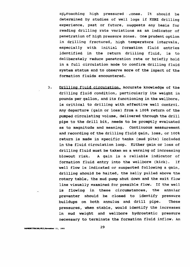
a~~roaching high pressured ~ones. It should be
determined by studies of well logs if KERZ drilling
experience, past or future, suggests any basis for
reading drilling rate variations as an indicator of
penetration of high pressure zones. One prudent option
in drilling fractured, high temperature intervals,
especially with initial formation fluid entries
identified in the return drilling fluid, is to
deliberately reduce penetration rate or briefly hold
in a full circulation mode to confirm drilling fluid
system status and to observe more of the impact of the
formation fluids encountered.
3. Drilling fluid circulation. Accurate knowledge of the
drilling fluid condition, particularly its weight in
pounds per gallon, and its functioning in the wellbore,
is critical to drilling with effective well control.
Any departure (gain or loss) from a 100% return of the
pumped circulating volume, delivered through the drill
pipe to the drill bit, needs to be promptly evaluated
as to magnitude and meaning. Continuous measurement
and recording of the drilling fluid gain, loss, or 100%
return is made in specific tanks (mud pits) included
in the fluid circulation loop. Either gain or loss of
drilling fluid must be taken as a warning of increasing
blowout risk. A gain is a reliable indicator of
formation fluid entry into the wellbore (kick). If
well flow is indicated or suspected following a gain,
drilling should be halted, the kelly pulled above the
rotary table, the mud pump shut down and the exit flow
line visually examined for possible flow. If the well
is flowing in these circumstances, the annular
preventer should be closed to identify pressure
buildups on both annulus and drill pipe. These
pressures, when stable, would identify the increases
in mud weight and wellbore hydrostatic pressure
necessary to terminate the formation fluid inflow. An
m:Wl~/11t.D~ 11, 1992 29

ev~Luation of the option of Ci ~ulating cool water in
the wellbore should be made if the kick is associated
with a temperature increase.
Partial or complete loss of drilling fluid returns is
the more common problem consequent to fracture
penetration. Complete loss of circulation, followed by
a falling fluid level in the wellbore annulus is a most
likely trigger for a blowout event. Drilling must be
halted, the drilling string pulled up Conly to the
first drill pipe tool iointl and the preventer closed
until the situation is evaluated and a response
determined.
4. Formation fluid entry. All geothermal fluid bearing
zones, both high and normally pressured, will be first
identified by the drill bit penetration, with a
subsequent charge of gases into the drilling fluid
upflow in the annulus. Mud logging systems will
automatically measure and record carbon dioxide,
hydrogen sulfide, methane and ethanol in parts per
million on a log scale whenever the drilling fluid is
being circulated. Although this information has a time
lag compared to the immediacy of a drilling break, it
is the most positive specific indicator that geothermal
fluids have been encountered. Gas-cut drilling fluid
returns, coupled with temperature increases, are a
clear warning that a high pressure zone of considerable
flow potential may be at hand. With additional
penetration, geothermal formation liquid fractions may
cause detectable salinity increases in the return
drilling fluid. Salinity determinations are not an
automated monitoring procedure, but are optionally
performed by the mud logger in evaluating fluid entry
events.
5. Secondary mineralization. Geothermal fluid bearing
faults, fractures and zones are predominantly enclosed
30

in a sheath or seal of secondaLy minerals. secondary minerals are continuously identified and recorded in
geothermal mud logging with the intent of discerning, in correlation with the wellbore temperature profile,
the most prospective intervals for fluid production. Logic would suggest that the larger hot fluid conduits,
which present both significant production potential and blowout risk, would likely have a thicker sheath of
secondary minerals. The extent to which this prevails in the Hawaiian rift zones and to which it may be a
particular precursor to high pressured geothermal fluids in fractures is not well known. Natural
variations in the secondary mineralization process, consequent to a new fracture opening for geothermal
fluid conduction, may be extreme; any secondary mineral sheath could presage a fluid filled fracture or a
fracture that is completely sealed by mineralization, particularly in the active faulting and fracturing of
the KERZ. Whatever may be the present view of this
apparent index, it appears to merit careful evaluation
within the concept of integrated monitoring as a
logical part of blowout prevention strategy.
B. DRILLING WITH AIR, AERATED LIQUIDS OR FOAM
These drilling fluids are utilized in the underbalanced drilling option, which is often employed in geothermal drilling,
particularly in known vapor dominated reservoirs. Air or aerated liquids drilling, signified by substantial additional equipment
and service requirements, (air compressors, rotating head, banjo box, blooie line, drilling muffler and H,S abatement backup) has
been employed on a geothermal exploration well in the KERZ.
Expectedly, air and aerated fluids drilling will be used and
further evaluated in the Hawaii environment. Air drilling eases the driller's concern with circulated fluid controls on formation
fluids; the formation fluids, with relatively unrestrained entry
to the annulus, are transported to the surface and through the
drilling muffler for chemical and noise abatement before release
31

to the atmosphere. The mud logger's int~rpretation of rock and mineral cuttings is degraded somewhat by the much reduced rock
particle size produced by air drilling. Otherwise the drilling monitoring procedures discussed above will apply for the same objective of blowout risk reduction.
SUMMARY
An optimal use of monitored drilling information in a blowout
prevention strategy requires the informed participation and responses of competent drillers and mud loggers. A logical assignment of
primary responsibility for the categories discussed above would be:
Driller drilling penetration rate drilling fluid circulation
Logger temperature variations secondary mineralization formation fluid entries
Computer based graphic data presentations are increasingly used at the driller's stations to quickly provide both present status and
cumulative record on the drilling and fluid circulation processes. Both caution and alarm thresholds can be set on the incoming real time
information streams to alert drillers and supervisors to upset
conditions. such systems offer an advantage to the blowout prevention
objectives necessary to Hawaiian geothermal drilling, provided that competence in their use is created by diligent training.
The mud logging services contracted to most of the geothermal drilling operations in the KERZ have been state of the art quality at
the time of every execution. Very substantial improvements in reliable automation have been made since the mid-1980s. In summary, Operators
have adequate monitoring procedures at hand to reduce blowout risks. The driller's main focus is on immediate deviations from the
contr~lled drilling process, and the mud logger's main focus is on subsurface physical consequences of borehole advancement. Blowouts
are commonly preceded by multiple warning signs of increasing risks.
The Operator's drilling engineers and geologists, with the close
cooperation of drillers and mud loggers, can more accurately recognize
such risks and more quickly act to control or reduce them with the
~/lftD~ 11, li92 32

drilling monitorH•.,I procedures discussed hen ..
A final comment should be made on drilling fluid monitoring
requirements while tripping the drilling string. Frequently in
geothermal well drilling with mud and water, the hydrostatic pressure
of the fluid has only a moderate overbalance on the formation fluids.
This is further reduced with the cessation of circulation immediately
before pulling the drill string, as for a new bit. In hot,
prospective rock zones, the large diameter drilling assembly moving
up hole can swab, or pull, formation fluids into the borehole, by
further reducing the hydrostatic pressure below the bit. The greatest
danger of swabbing occurs when pulling the first few stands of drill
pipe (drilling assembly just pulling off bottom). At this point, a
careful confirmation of the drilling fluid fill-up volume, required
to hold the fluid level at the wellhead, is essential. If the well
fill-up volume is less than the volume of drill pipe pulled, swabbing
should be inferred, the bit returned to the bottom and the hole
recirculated to clear the formation fluids from the well. In summary,
swabbing is a mechanism that can and has caused blowouts. A slower
pulling of the initial stands and the fill-up check are the defensive
procedures to use.
~ncaiWC;fiiLD/')I09'albe' 11, 1992 33

VII. KICK CONTROL
INTRODUCTION
In drilling terms, a 'kick' is often the first indication at the wellhead that there are problems with control of formation pressure.
A kick is defined as the entry of formation fluids (water, steam, or gasses) into the well, which occurs because the hydrostatic pressure
exerted by the drilling fluids column has fallen below the pressure of the formation fluids. If prompt action is not taken to control the
kick and to correct the pressure underbalance, a blowout may follow. Some of the main causes of these pressure imbalances are:
1. Insufficient drilling mud weight. 2; Failure to properly fill the hole with fluids during trips.
3. Swabbing when pulling pipe. If the drill string is pulled
from the hole too rapid! y, the pressure may be reduced,
allowing formation fluids into the bore. 4. Lost circulation.
KICK IDENTIFICATION
There are a number of warning signs that indicate that a kick is
occurring or that it may soon occur. Some of these signs, which may
not be present in all situations, are:
1. An increase in the returning drilling fluids flow rate,
while pumping at a constant rate. 2. An increase in mud pit volume.
3. A continuing flow of fluids from the well when the pumps
are shut down. 4. Hole fill up on trips is less than the calculated amount.
5. A pump pressure change and a pump stroke increase while
drilling.
6. An increase in drill string weight.
7. A drilling break. (A sudden increase in penetration rate)
BOPKlCU/WLD/BIII~ 11, 1992 34

8. Gas cut mud or reduced mud weight ~~ the flow line.
9. Lost circulation.
10. A rapid increase in flow line temperature.
Each of the above warning signs individually does not positively
identify a kick. However, they do warn of a potential for a kick.
Every driller and derrickman should be expert in recognizing these
indicators and all crew members should be trained to take action. In
geothermal drilling, in addition to being alert to the above warning
signs, it is of prime importance to: 1) monitor drilling fluid
temperatures in and out while drilling; 2) maintain a frequent and
close analysis of the formation cuttings for a change in
mineralization; and 3) exert caution when drilling through formations
where lost circulation zones are expected. Difficulties or abnormal
conditions with any of these indications or procedures can also
indicate a potential kick.
SHUT IN PROCEDURES
The severity of a kick depends on the volume and pressure of the
formation fluid that is allowed to enter the hole. For this reason,
it is desirable to shut the well in as quickly as possible. When one
or more warning signs of a kick are observed, procedures should be
started to shut in the well. If there is doubt as to whether a kick
is occurring, shut in the well and check the pressures and other
indicators.
Specific shut in procedures when one or more kick warning signs
are observed:
1. WHILE DRILLING
a. Pick up kelly until a tool joint is above the table.
b. Shut down the mud pumps.
c. Close the annular preventer.
d. Notify the company supervisor.
e. Record the drill pipe and annular pressure build up.
2. WHILE TRIPPING
a. Pick up kelly until a tool joint is above the table.
35
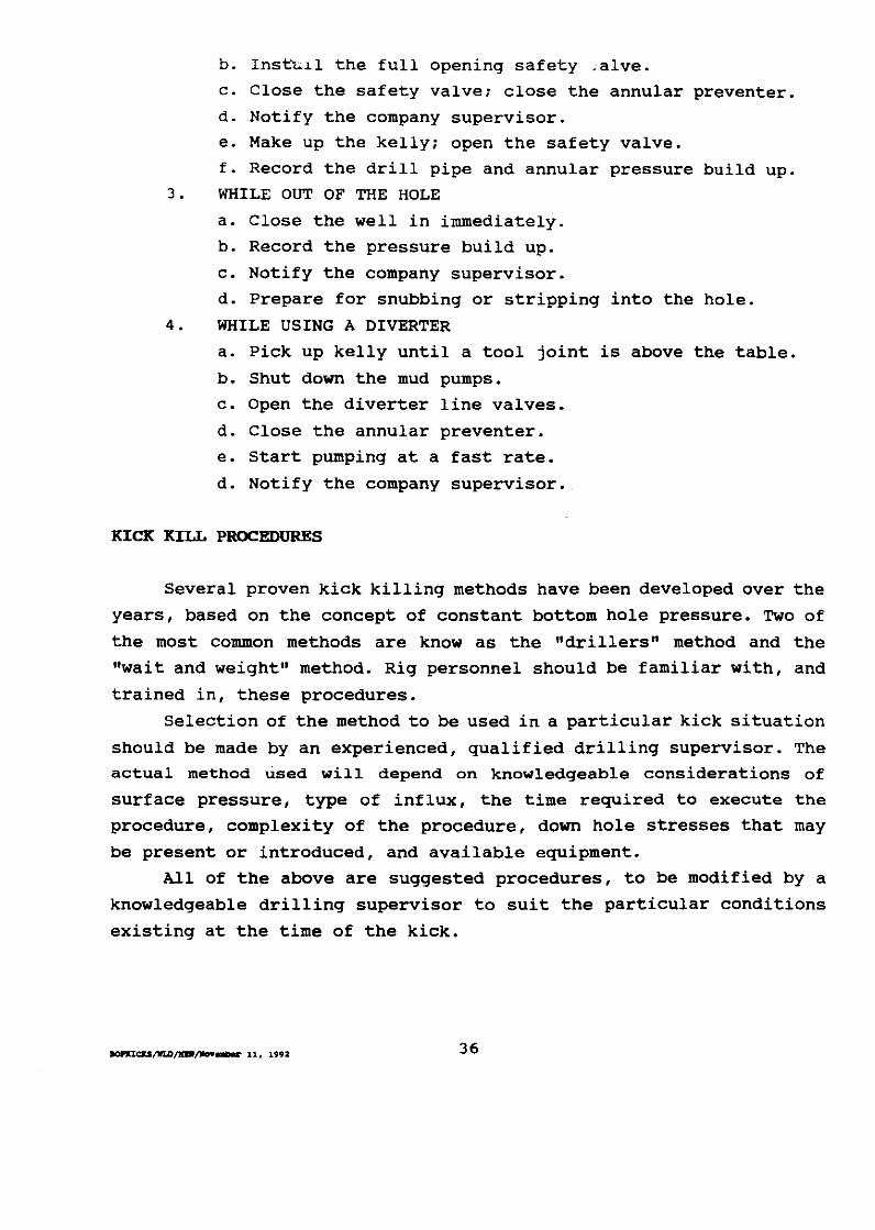
b. Inst-~.11 the full opening safety .alve.
c. Close the safety valve; close the annular preventer.
d. Notify the company supervisor.
e. Make up the kelly; open the safety valve.
f. Record the drill pipe and annular pressure build up.
3. WHILE OUT OF THE HOLE
a. Close the well in immediately.
b. Record the pressure build up.
c. Notify the company supervisor.
d. Prepare for snubbing or stripping into the hole.
4. WHILE USING A DIVERTER
a. Pick up kelly until a tool joint is above the table.
b. Shut down the mud pumps.
c. Open the diverter line valves.
d. Close the annular preventer.
e. Start pumping at a fast rate.
d. Notify the company supervisor.
KICK KILL PROCEDURES
Several proven kick killing methods have been developed over the
years, based on the concept of constant bottom hole pressure. Two of
the most common methods are know as the "drillers" method and the
"wait and weight" method. Rig personnel should be familiar with, and
trained in, these procedures.
Selection of the method to be used in a particular kick situation
should be made by an experienced, qualified drilling supervisor. The
actual method used will depend on knowledgeable considerations of
surface pressure, type of influx, the time required to execute the
procedure, complexity of the procedure, down hole stresses that may
be present or introduced, and available equipment.
All of the above are suggested procedures, to be modified by a
knowledgeable drilling supervisor to suit the particular conditions
existing at the time of the kick.
36

VIII. BLOWOUT CLASSIFICAi)ON
INTRODUCTION
Any uncontrolled flow of steam, brine or other well fluids
constitutes a blowout. A discharge of these fluids at the surface is
usually taken as the basic identifier of a blowout. However, surface
discharge, if it occurs, is only the symptom or consequence of the
fundamental upset condition that results in a blowout.
In the context of Hawaii geothermal activities, a broader, yet
more precise, definition of a blowout: can be stated as a "loss of
control of the natural pressures and fluids encountered in the
drilling of a geothermal well."
There are several types of geothermal well blowouts, varying in
their severity and in the techniques needed to control them. The
impacts on surface and subsurface environments, resource waste, and
public perceptions of these incidents demand that Operators and
regulators minimize the risks of blowouts. The types of blowouts that
may be experienced in Hawaii include the following:
A. SURFACE BLOWOUTS
1. Casing contained. An uncontrolled flow of steam or other
fluids through the casing and wellhead will result in the
escape of fluids to the atmosphere. This may result in
unabated gas emissions and noise disruptive to the
surrounding community and the surface environment
surrounding the well. This type of blowout may cause minor
to major damage to the wellhead, BOP equipment stack, or
drilling rig. Response to the blowout will depend on the
specific situation. Efforts will focus on wellhead repairs,
control of fluid discharge, and access to the area for
specific procedures. The availability of drilling fluid
supplies (including water), and the condition of the
37

drillin string and casing will key elements in an effective operation to regain well control.
2. Externally Vented. Moderate case low-to-moderate fluid venting
outside the casing or the cellar; the drilling rig, wellhead and BOP are generally undamaged and operable. May or may not be disturbing to surrounding community.
Responses may include grouting at the leak to terminate surface flow.
• Worst case - venting volume and/or velocity leads to rig collapse and/or cratering around or near the
wellhead. Response will probably require a relief well if the hole doesn't bridge or collapse on its own, thus terminating the flow.
B. UHDERGROUHD BLOWOUTS
Although this class of blowout lacks any surface display, the event could escalate into a surface blowout if not recognized and
resolved at an early time.
~ High pressure fluid upflows, in the open hole, from a
deep zone to a shallower permeable zone (lower temperature
reservoir or groundwater) . Such events may range from serious degradation or destruction of the open hole, to
minor resource loss and conservation problems. Response is generally to subdue the flow with water, weighted muds, or cement plugs as required. Additional casing/liner probably will be required, or the well may be plugged with cement for
redrill or suspension.
l..... High pressure fluid upflows, in the open hole, from a deep zone to an escape by hydraulic fracturing at the
deepest casing shoe, where the formation (pressure) gradient is exceeded by higher fluid pressure from the deep zone.
Response as above in 1.
38

IX. SUPERVISION AND TRAINING
INTRODUCTION
The major cause of most blowouts is human error; either none of the crew or the Operator's advisors recognizes an existing well control problem, or steps to control the situation are not performed soon enough. Most blowouts are fully preventable by properly trained drilling personnel. Thus, proper training of the crew is as important to successful well control as is the proper selection and use of blowout prevention equipment, as discussed in the preceding sections.
The Hawaii conditions for geothermal drilling require that every Operator recognize its prime responsibilities to provide supervision
and training that is several levels above the industry average. Hawaii's geothermal drilling industry is still in a formative
stage. Because there is no pool of operators and drilling personnel thoroughly familiar with all potential problems in Hawaii's geothermal resource areas, there is a need for operators, drilling contractors and regulators to pay extraordinary attention to all elements of
training for their personnel. There must be a proper balance between practical, on-the-job-training, operational drills, and formal study
for a wide range of individual experience levels. In a few cases, drilling and monitoring crews will have worked together closely in
other geothermal areas, some of which may exhibit well control challenges similar to Hawaii's. In other instances, crews will be made
up of a mixture of individuals that have not worked as a team before, and may have a larger percentage of new workers, especially at lower skill levels in the drilling and pr~duction jobs.
An additional consideration in the Hawaii case is the known occurrences of relatively high levels of H,S gas in the geothermal resource. Proper well planning and equipment selection can mitigate many of the hazards of H,S drilling in the well control sense, but it
is necessary that all drilling crews have a clear understanding of the
dangers and rules that accompany drilling in known H,S zones.
~ta»tarl ....._. 11, 1192 39

SUPERVISORY EXPER- .>HCE
Although complete training for specific crews that will drill in
Hawaii's geothermal zones is of primary importance, the art of well
control is not learned from classroom training alone. Therefore,
experienced supervisory personnel are vi tal to the process of training
the drilling crews, as well as in lending their experiences to the
ongoing supervision of the drilling. Drilling plans submitted should
discuss the levels of experience of the drilling crews, supervisors,
consultants and managers, with comment on the methods to be taken to
ensure that such experienced persons will be directly involved while
drilling activities are underway in Hawaii.
DRILLING TEAM TRAINING AND DRILLS
The training of drilling teams, including supervisory, management
and operating personnel, in well control and blowout protection can
be discussed in three basic levels. Level one:training through formal
courses that are infrequently offered by industry and regulatory
organizations, often at a regional or national level; level two: the
training that an Operator conducts on a more or less formal, or
classroom, basis with its drilling supervisors, drilling crews, and
others who directly support its Hawaii drilling operations ; level
three: Operators must have a program of drills that ensure all
personnel actually have 'hands-on' experience with the installed
blowout prevention equipment.
A number of organizations conduct training and certification in
well control, mainly directed toward the petroleum drilling industry.
However, recent classes in the specifics of geothermal well control
have been held by a cooperative effort of the Geothermal Resources
Counc.i,l and the National Geothermal Association, with funding in part
by the Federal DepartBent of Energy. This course has been approved
by the Federal Minerals Management service for training and
certification in well control subjects, and is recommended for
supervisory and other drilling personnel, as an indication of the
level of specific well control training and experiences of these
BOP'l».DmmG/ID/Irl llcw.-bu 11, 1992 40

personnel assigne~ to Hawaii drilling tasks. rhere are no plans to hold these formal courses often, and most certainly not in concert with specific drilling schedules of individual projects. Therefore, each Operator and drilling contractor will need to supplement the experiences of their supervisory personnel with direct team training
pointed toward developing an integrated effort for Hawaiian projects.
Operators should outline the formal (classroom) training proposed
for drilling personnel, with specific references to 'kick' recognition and blowout prevention, including monitoring systems, equipment, and
drilling procedures. A number of study guides and references are available for these purposes; publications to be used should be listed
in drilling plans so that they can be reviewed by regulatory review
personnel. A list of specific references is not included in this
Manual because these publications may become obsolete by newer editions. Appendix c, References, contains documents and sources used
in preparing this Manual, and should be consulted for suitability to
each drilling plan.
In addition to classroom training and periodic updates as drill
crews may shift or the drilling may enter new phases, blowout
prevention drills should be conducted on a regular (but unannounced)
basis to provide further training, and to keep crews focussed on the
possibilities of well kicks, and blowouts. Crews should be familiar
with the equipment in use, and be able to properly and safely shut in
the well before a control problem becomes dangerous to personnel or
the well itself. These drills should be directed at well control and proper blowout prevention procedures in three basic situations - when
drilling ahead, when 'tripping out' of the well, and when the drill
pipe is out of the wellbore.
Other blowout prevention and general safety training - both
informal and on-the-job situations, should be outlined in the drilling
plan. Subjects covered should include new employee orientation,
visitor briefings and general safety training. Formal training
sessions, regular review training and blowout prevention drills held
should be noted in the daily reports of the drilling operation.
41

X POST COMPLETION BLOWOUT p'J(EYENTION
It is important to realize that blowout risks are not restricted
to the initial drilling and completion of a geothermal well. At a much
lower incidence rate, blowouts can occur at producing wells and at
shut-in idle wells. Wellhead equipment should be recognized as
vulnerable to natural surface conditions and vandalism. The capacity,
integrity, and security of geothermal wellhead equipment are all the
responsibility of a production engineering expertise which is not
within the scope of this Blowout Prevention Manual.
Two areas of subsurface risks to casing string integrity in
existing Hawaiian geothermal wells should be noted. The corrosion
potential of wellbore fluids, in both the production and shut-in
(static) modes should be identified. Baseline chemistry and casing
evaluation procedures should be established shortly after well
completion. The objectives here are to assure and prolong casing
integrity, and to preclude any blowout consequent to a casing failure
due to corrosion. Wells that have been tested or have produced high
temperature fluids, and then are shut-in for periods of time,
particularly require regular and accurate monitoring of casing
conditions. Temperature decreases imposed by the active Hawaiian
ground water regime can accelerate H,S corrosion in shallow casing
strings in idle wells. Finally, the risk of casing failure in rift
zone eruptions and earthquakes (shallow fault movements, ground
disruption or rotational failures) should be recognized.
Blowout prevention requirements during remedial work, redrills,
recompletions and abandonments, in all geothermal wells, must be
evaluated and provided for by the same process of consideration
required in every new geothermal well drilling permit proposal.
~/WUJ/]Ia"nnlbu' 11, liltll: 42

,,.~ ~,
XII BLOWOJJT PREYENTION IN SI.IMHOI.ES
INTRODUCTION
Deep drilling with slimhole (approximately 4-6 inch bit
diameters) technology and equipment has achieved major advances in the
mining industry in the last several decades. However, the mining
drilling environment does not present pressure control problems
comparable to those encountered in petroleum and geothermal drilling.
For this reason, well control practices in slimholes were poorly
understood until recently. This hindered an expanding use of the
technology. However, the technical and economic advantages of
slimholes have recently registered with several petroleum companies;
Amoco Production Company has particularly investigated the
requirements of well control and blowout prevention in slimhole
drilling.'
KEY ATTRIBUTES
Much smaller volumes of drilling fluids are circulated in
slimholes. Kicks of any volume are of more consequence, and immediate
detection of fluid entry, or lost circulation, is critical.
Quantitative electromagnetic flow meters are used to measure drilling
fluid entry and exit volumes at the wellhead. These flow meters are
reliable and accurate, measuring gains of one barrel or less as
compared to pit gains of 15 barrels or more as frequent kick events
in the standard drilling mode. Unfortunately, the much greater size
of this type of meter required for standard diameter wellbores make
them cost prohibitive. Another feature of importance is the high
annular pressure loss (APL) incurred by drilling fluid circulation in
'Well Control Methods and Practices in small-Diaaeter Wellbores; D. J. Bode, et al Amoco Production co., October 1989. (Available from the Society of Petroleum Engineers, P. o. Box 833836, Richardson, Texas 75083-3836; Telephone 214-669-3377.)
43

slimholes. The hig,i.er rotary speeds (RPM) usea in slimholes also adds,
with the APL, a substantial increase (overbalance) above the
hydrostatic pressure of the drilling fluid on the borehole while
actively drilling or coring. This physical phenomena relates to the
very small annuli between drill tubulars and the rock wall. The high
APL can be used advantageously to effect a dynamic kill and control
of formation fluid entry below 2, 500-foot depths in slimhole by
accelerating the pumping rate to maximum levels in circulating out the
intruding fluids. In summary, blowout prevention in slimholes requires
special training, precision flowmeters, real time data presentation
and dynamic kill proficiency. It is likely that additional slimhole
drilling will be considered in Hawaii geothermal exploration and
development; Operators should carefully evaluate the Amoco paper
referenced when developing plans for these boreholes.
44

HAWAII GEOTHERMAL BLOWOUT PREVENTION MANUAL
APPENDIX A
MANUAL REVIEW AND REVISIONS

APPENDIX A-
MANUAL REVIEW AND REVISION
Geothermal drilling experience in Hawaii, as of mid 1992, has
been quite limited. Only 14 deep geothermal boreholes had been drilled, and these were located on only one prospective feature, the
KERZ. Reasonable increases in geothermal drilling in the KERZ, and perhaps other areas, can be anticipated. New operational and
regulatory experiences should accumulate in the next few years. This Blowout Prevention Manual can best be accepted as a first
edition. Ideally, it should serve as a working reference for operators and regulators in a cooperative approach to the achievement of blowout
risk reduction. It is recommended that this Manual be reviewed and revised within
5 years of its date of issue by DLNR. such a time interval seems ample for the collection of new operating information and for a reasonable
application of the blowout prevention procedures recommended in the Manual. Frequent and informed discussion of blowout prevention
procedures between operators and regulators could prove to be one of
the most important consequences of the use of this Manual.
APPENDIX A-1

HAWAII GEOTHERMAL BLOWOUT PREVENTION MANUAL
APPENDIX 8
ILLUSTRATIONS

'·
HAWAII GEOTHERMAL DIVERTER STACK
Fi9ure I.
A 2M ANNULAR PREVENTER
FLOW TEE or BANJO BOX
API ARRANGEMENT SA
2000 PSI
s
12"

HAWAII GEOTHERMAL FULL BOP STACK
Figure 2.
ROTATING HEAD
G I When usinll air
-installed on top of ANNULAR PREVENTER
RAM PREVENTER
RAM PREVENTER
FLOW TEE or BANJO BOX
CHECK VALVE
KILL 2" .C~JXID
API ARRANGEMENT RSRS RRA
MIN. 3000 PSI
A
R
R
s
R
R
ANNULAR PREVENTER
Remotely operated -VALVE
VENT/BLOOIE 12"
BLIND RAM
Remotely operated VALVE
CHOKE 4"
PIPE RAM

FIGURE 3
In Hawaii, where wellhead temperatures in excess of 600"F may
occur, Operators must consider the pressure derating of steel due to elevated temperatures when selecting wellhead equipment. The table
below, from the Aaerican Petroleum Institute (API) Specification 6A, provides the recommended working temperatures for steel at high
temperatures; this table goes only to 650"F.
In addition to the steel in wellhead equipment, the temperatures
found in Hawaii far exceed the temperature ratings of elastomers
found in most BOP equipment. Operators often use all steel rams in
ram type preventers for a more effective seal. The API recognizes temperature ratings of elastomers up to. 250"F, but some manufacturers
can now produce elastomers that are rated to 420"F.
APPENDIX B, FIG 3 -1
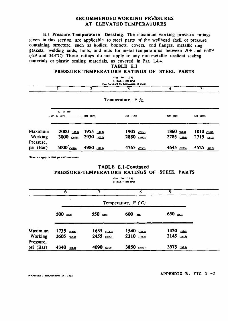
RECOMMENDED WORKING PR'ESSURES AT ELEVATED TEMPERATURES
E.1 Pressure-Temperature Derating. The maximum working pressure ratings given in this section are applicable to steel parts of the wellhead shell or pressure containing structure, such as bodies, bonnets, covers, end flanges, metallic ring gaskets, welding ends, bolts, and nuts for metal temperatures between 20F and 650F ( -29 and 343 •q. These ratings do not apply to any non-metallic resilient sealing materials or plastic sealing materials, as covered in Par. 1.4.4.
(-~2
Maximum Working
Pressure, psi (Bar)
TABLE E.1 PRESSURE-TEMPERATURE RATINGS OF STEEL PARTS
(See Pu. U<l (I BAJ. • 100 t:PI)
(Sec Porewonl fOI" 8 Kp'n.ec. of Ullill)
I 2 3 4
Temperature, F t!b
-20 '"""' Ill l~ll JOO Uill "" Ulll "" (lg!l
2000 ill!2l 1955 {134.1} 1905 03l4l 1860 illYl
3000 = 2930 = 2880 = 2785 = 5ooo·UW! 4980 l.lli.ll. 4765 = 4645 =
5
"" !ml.
1810 ill!1l
2715 = 4525 LlllJil.
• Does •ot apply to 5000 pli 6BX cou.ectiou
Maximlfm Working
Pressure, psi (Bar)
TABLE E.1-Continued PRESSURE-TEMPERATURE RATINGS OF STEEL PARTS
6
500 atm.
1735 llWl
2605 t!ZW
4340 !299.21
7
(Sec Par. 1.2.4)
(I BAR=- 100 II:PI.)
8
Temperature, F ('C)
550 WI!
1635 ii.Wl
2455 J.a2Jl
1540 ~ 2310 = 3850 !215.>1
9
650 lJ!.ll
1430 lWl
2145 = 3575 !:!A6.>l
APPENDIX B, FIG 3 -2

HAWAII GEOTHERMAL BLOWOUT PREVENTION MANUAL
APPENDIX C
REFERENCES

APPENDIX C
REFERENCES
Adams, N., Well Control Problems and Solutions, Petroleum Publishing Company, 1980.
An Applicant Guide to State Permits and Approvals for Land and Water Use Development, Department of Planning and Economic Development, State of Hawaii/Coastal Zone Management, 1986.
API Recommended Practices For Safe Drimn~ of Wells Containjn~ H.S - RP49, The American Petroleum Institute, 1974.
Blowout Prevention EQuipment Systems for Dril!jn~ Wells - RP 53, 2nd Ed The American Petroleum Institute, 1984.
Bode, D. J., Noffke, R. B., and H. V. Nickens, Amoco Production Company, "Well Control Methods and Practices in Small-Diameter Wellbores", Society of Petroleum Engineers, October 1989.
Diener, D., Introduction to Well Control, Petroleum Extension Service, University of Texas at Austin, 1981.
Goins, W. C., Blowout Prevention Practical Dril!jn~ Technolo&)' - volume 1, Gulf Publishing Company
Hallmark and Wygle, Oil and Gas Blowout Prevention in California - Manual #M07, 2nd Edition, California Division of Oil and Gas, 1978.
Hills, A, Oyerview of the Status Development Approach and Financial Feasibi1ity, Department of Business and Economic Development, State of Hawaii, 1988.
Planning for Drimog in U.S Zones - An Outline of Safety and Health PrOCedures, Petroleum Extension Service, University of Texas at Austin, 1978.
Rowley, J. "Geothermal Standards .. A Decade of Leadership Continues" Geothermal Resources Council Bulletin, December 1991.
Geothermal Re&Jllations and Rules of Practice & Procedure. State of Nevada.
Rules for Geothermal and Cable System Development P!annin~. Title 13 -Administrative Rules, Department of Land and Natural Resources, Sub-Title 7. Water and Land Development, Chapter 185. State of Hawaii.
BOPUPBI.BNCBS-APPENEC/I.AP/Nona~Mr II, 1992 Appendix C-1

Rules on Leasin& ana" brimne of Geothermal Resources, Iitle 13 - Administrative Rules, Department of Land and Natural Resources, Sub-Title 7. Water and Land Development, Chapter 183. State of Hawaii
State Wjde Geothermal Re~latioos. California Administrative Code -Title 14, Natural Resources; Chapter 4, Sub-Chapter 4 - State of California.
Sumida, Gerald A, Alternative Approaches to the Le&al Institutional and Financial ASllects of Deyelopin& an Inter-Island Electrical Trapsmjs.sjon Cable System, Carlsmith, Wichman, Case, Mukai and Ishiki and First Interstate Cogeneration Capital Associates for the Department of Planning and Economic Development, State of Hawaii, April 1986.
Thomas, Richard, Whiting, R., Moore, J., and Milner, D., lpdependept Technical Inyestjeation of the Pupa Geothermal venture Upplanped Steam Release, Jupe 12 and 13, 1991 Puna Hawaii, for the State of Hawaii/County of Hawaii, July 1991.
BOPRIIPKUNCBS-J.PPBMII:/L\P/~ 11, 1992 Appendix C-2

HAWAII GEOTHERMAL BLOWOUT PREVENTION MANUAL
APPENDIX D
GLOSSARY

APPENDIX D
GLOSSARY
A
accumulator n: 1. on a drilling rig, the storage device for nitrogen-pressurized hydraulic fluid, which is used in closing the blowout preventers.
annular blowout preventer n: a large valve, usually installed above the ram preventers, that forms a seal in the annular space between the pipe or kelly and wellbore or, if no pipe is present, on the wellbore itself.
API ~: American Petroleum Institute
8
BHP ~: bottom hole pressure.
BHT ~: bottom hole temperature.
blowout n; A blowout is an uncontrolled flow of formation fluids or gas from a well bore into the atmosphere or into lower pressure subsurface zones. A blowout occurs when formation pressure exceeds the pressure applied by the column of drilling fluid.'
BOP equipment n: The entire array of equipment installed at the well to detect and control kicks and prevent blowouts. It includes the BOP stack, its actuating system, kill and choke lines, kelly cocks, safety valves and all other auxiliary equipment and monitoring devices.
bottoa hole temperature n: The temperature of the fluids at the bottom of the hole. While drilling, these temperatures may be measured by minimum reading temperature devices, which only record temperatures above a designed minimum, and may not provide an accurate bottom hole temperature. Bottom hole temperature readings should be recorded after a period of fluids circulation at a particular depth, in order to stabilize the reading.
blowout preventer n: the equipment installed at the wellhead to
1 Rotary Dr ill ing BLOWOUT PREVENTION Unit I II , Lesson 3 ; Petroleum Extension Service, The University of Texas at Austin, Austin Texas, in cooperation with the International Association of Drilling Contractors, Houston Texas. 1980; 97 pages.
BOPGLOSSAJlY/ItAPIN~Il. 1992 Appendix D-1

prevent or control the escape of high pressur,. formation fluids, either in the annular space between the casing and drill pipe or in an open hole (i.e., hole with no drill pipe) during drilling and completion operations. The blowout preventer is located beneath the rig at the surface. see annular blowout preventer and ram blowout preventer.
BOP ~= blowout preventer
BOP stack n: The array of preventers, spools, valves and all other equipment attached to the well head while drilling.
borehole n: the wellbore; the hole made by drilling or boring.
c cap rock n: 1. relatively impermeable rock overlying a geothermal reservoir that tends to prevent migration of formation fluids out of the reservoir.
casing n. steel pipe, cemented in the wellbore to protect it against external fluids and rock conditions, and to facilitate the reliable and safe production or injection of geothermal fluids.
cellar n: a pit in the ground to provide additional height between the rig floor and the wellhead, and to accommodate the installation of blowout preventers, rathole, mousehole, and so forth. It also collects drainage water and other fluids for subsequent disposal.
ceaenting n: the application of a liquid slurry of cement and water to various points inside or outside the casing.
coapetent rock n. (in wellbores) any rock that stands without support in the drilled wellbore can be described as competent. Beds of ash, or loose volcanic clastics, are vulnerable to failure in open wellbores, and are thus considered to be incompetent rock.
complete shut off n. a full closure and containment of wellbore fluids and pressure at the wellhead.
conductor n: 1. a short string of large-diameter casing used to keep the top of the wellbore open and to provide a means of conveying the up-flowing drilling fluid from the wellbore to the mud pit. 2. a boot.
cso ~= complete shut off.
D
diverter n: a system used to control well blowouts when drilling at relatively shallow depths by directing the flow away from the rig. The diverter is part of the BOP Stack that includes an annular preventer with a vent line beneath. A valve on the vent line is
BOPOLOSSAAY/IAJII~ll, 1992 Appendix D-2

installed so that it is opened whenever the aunular preventer is closed.
drill collar n: a heavy, thick-walled tube, usually steel, used between the drill pipe and the bit in the drill stem to provide a pendulous effect to the drill stem.
drilling fluid n: a circulating fluid, one function of which is to force cuttings out of the wellbore and to the surface. While a mixture of clay, water, and other chemical additives is the most common drilling fluid, wells can also be drilled using air, gas, or water as the drilling fluid. Also called circulating fluid. See mud.
drilling spool n: a spacer used as part of the wellhead equipment. It provides room between various wellhead devices (as the blowout preventers) so that devices in the drill stem (as a tool joint) can be suspended in it.
drill pipe n: the heavy seamless tubing used to rotate the bit and circulate the drilling fluid. Joints of pipe are coupled together by means of tool joints.
drill string n: the column, or string, of drill pipe with attached tool joints that transmits fluid and rotational power from the kelly to the drill collars and bit. Often, the term is loosely applied to include both drill pipe and drill collars. Compare drill stem.
F
flange n: a projecting rim or edge (as on pipe fittings and opening in pumps and vessels), usually drilled with holes to allow bolting to other flanged fittings.
formation pressure n: the force exerted by fluids in a formation, recorded in the hole at the level of the formation with the well shut in. Also called reservoir pressure or shut-in bottom-hole pressure. See reservoir pressure.
J
joint n: a single length of drill pipe or of drill collar, casing, or tubing, that has threaded connections at both ends. Several joints, screwed together, constitute a stand of pipe.
K
kelly n: the heavy steel member, four-or six-sided, suspended from the swivel through the rotary table and connected to the topmost joint of drill pipe to turn the drill stem as the rotary table turns. It has a bored passageway that permits fluid to be circulated into the drill stem and up the annulus, or vice versa.
BOPOLOSIAIY/ItAP/N«mmiiNI'Il, 1991 Appendix D-3

kelly cock n: a valve installed between the swivel and the kelly. When a high-pressure backflow begins inside the drill stem, the valve is closed to keep pressure off the swivel and rotary hose. See kelly.
kick n: an entry of water, gas, or other formation fluid into the wellbore. It occurs because the hydrostatic pressure exerted by the column of drilling fluid is not great enough to overcome the pressure exerted by the fluids in the formation drilled. If prompt action is not taken to control the kick or kill the well, a blowout will occur.
kill line n: a high pressure line that connects the mud pump and the well and through which heavy drilling fluid can be pumped into the well to control a threatened blowout.
L
L.C. ~= lost circulation
log n: a systematic recording of data, as from the driller's log, mud log, electrical well log, or radioactivity log. Many different logs are run in wells to obtain various characteristics of downhole formations. v: to record data.
lost circulation n: the loss of quantities of any drilling fluid to a formation, usually in cavernous, fissured, or highly permeable beds, evidenced by the complete or partial failure of the fluid to return to the surface as it is being circulated in the hole. Lost circulation can lead to a kick, which, if not controlled, can lead to a blowout.
M
manifold n: an accessory system of piping to a main piping system (or another conductor) that serves to divide a flow into several parts, to combine several flows into one, or to reroute a flow to any one of several possible destinations.
mud n: the liquid circulated through the wellbore during rotary drilling and workover operations. In addition to its function of bringing cuttings to the surface, drilling mud cools and lubricates the bit and drill stem, protects against blowouts by holding back subsurface pressures, and prevent loss of fluids to the formation. Although it was originally a suspension of earth solids (especially clays)- in water, the mud used in modern drilling operations is a more complex, three-phase mixture of liquids, reactive solids, and inert solids. The liquid phase may be fresh water, and may contain one or more conditioners. See drilling fluid •
.ud logging n: the recording of information derived from examination and analysis of formation cuttings suspended in the mud or drilling fluid, and circulated out of the hole. A portion of
BOPOLOIS.UY/RAP/~11, 1992 Appendix D-4

JQI-{N WAIHEE GQy,_::,-1NOF1 OF HAWAII
STATE OF HAWAII DEPARTMENT OF LAND AND NATURAL RESOURCES
DIVISION OF WATER AND LAND DEVELOPMENT
Mr. Ralph A. Patterson President R.A. Patterson & Associates 1274 Kika Street Kailua, Hawali 96734
Dear Mr. Patterson:
P. 0. BOX 373
HONOLULU, HAWAII 96809
SEP -1 1993
Geothermal Blowout Prevention Manual
KEITH W. AHUE, Chairperson
SOAF10 OF LAND AND NATUF1AL F1ESOUF1CES
DEPUTIES
JOHN P. KEPPELER, II DONA L. HANAIKE
AQUACULTURE DEVELOPMENT PROGF1AM
AQUATIC RESOURCES
CONSERVATION AND ENVIRONMENTAL AFFAIF1S
CONSERVATION ANO RESOURCES ENFORCEMENT
CONVEYANCES FORESTRY AND WILDLIFE
HISTORIC PRESERVATION
LAND MANAGEMENT STATE PARKS
WATER AND LANO DEVELOPMENT
Thank you for your August 9, 1993 letter and overall cooperation in preparing the Geothermal Blowout Prevention Manual.
Attached is a list of corrections to be made along with a marked-up copy for reference. A few context changes were necessary in order to provide accurate information and promote flexibility in the manual.
Should you have any questions on these r•u .. ,rs, please contact Mr. Gordon Akita of the Flood Control and Mineral Resource Branc at 5 7-0227.
U TAGOMORI r
JF:lc
En c.
,_,. ··'

Note:
CORRECTIONS FOR FINAL HAWAII BLOWOUT PREVENTION MANU!\L
Please see mark-up copy of the Manual for a referettce to the requested changes.
Text to be deleted is in [brackets]
Text to be added is underlined
Please make the following corrections:
1. Page after cover sheet, listing BLNR members and government officials: Misspelled KEPPELER.
2. Acknowledgement Page, bottom of first paragraph: Misspelled Tagomori.
3. Preface Page, middle of third paragraph: Delete [and], add an; Misspelled State.
4. Page 5, second paragraph: Please write as:
Primary features such as lava tubes, irreaular layers of ash and rubble contibute to very high horizontal permeabilitY..L whereas secondary features such as fractures contibute to very high vertical permeability; both features can pose a problem with loss of drilling fluid circulation and low rock strengths. These features seem to diminish downward, but appear to extend to depths of about 2000 feet.
5. Page 10, third paragraph, line 6: Delete [Commonly] from the beginning of the sentence; add commonly to line 7.
Example: The deliberate actions to optomize safety in geothermal drilling commonly will be specified or reflected in four distinct sections of the drilling plan, as follows:
6. Page 15, second paragraph, line 5: add while the drill string is.
Example: situations such as active drilling and tripping, or while the drill string is out of the hole.
7. Page 17, last line: Delete [Another possible arrangement might omit (continued on page 18) the ram preventer shown below the choke and fill line valves, saving the height of this valve. This would remove an important safety back-up in the event that the small valves fail or need repair; without this ram preventer there would be no last resort to preventing a
1

blowout in this area of the stack.]; add:
Another possible arrangement is to remove the lowermoJ3_t.~0P~ ram shown in Figure 2 and install it above the choke f!Jl~_ki.L!o lines, in tandem with the blind ram. A full BOP stack should be maintained at all times while drilling in the vicini_"ty··-;;f the production zone.
8. Page 24, bottom paragraph, line 6: add way.
Example: The imformation provided by way of monitoring procedures, with careful integration and evaluation, can make iportant contributions to an Opera tor's prevention strategy.
9. Page 27, last paragrpah, line 11: delete space to the left of the word "where".
10. Page 29, first paragraph, line 2· delete spaces after ttevents", "on", "other 11
, and before and after ''A''.
11. Page 32, bottom of page: underline Driller and Logger and format as follows:
Driller drilling penetration rate drilling fluid circulation
Logger temperature variations secondary mineralizatio11 formation fluid entries
12. Page 45, last paragraph, line 7: Delete space in middle of paragraph.
13. Appendix A-1, Manual Review and Revision: delete the last paragraph.
14. Appendix C-1, References:
15.
References 3 and 10: change superscripted 2 in 112
8 to subscript. Example: H2S
Reference 12: delete [Geothermal] at the end of the first line; add Geothermal at the beginning of the reference.
Example: Geothermal Regulations and Rules of Practice &
Procedure, State of Nevada.
Appendix C-2, line 2 ''Sumida,Gerald, A.": delete
2
of reference [and]; add an.
beginning with

Example: Sumida, Gerald A., Alternative Approaches to the Legal, Institutional and Financial Aspects of Developing an Inter-Island Electrical Transmission Cable System.
16. Appendix D-2, Glossary:
First paragraph: add a period (.) after ''surface''.
Definition of casing: add or injection; delete [from the well] :
Example: casing n. steel pipe, cemented in the wellbore to protect it against external fluids and rock conditions, and to facilitate the reliable and safe production or injection of geothermal fluids.
Delete second definition of casing.
17. Appendix D-5, Definition of pipe ram: delete [and] and ram.
Example: See ram and ram blowout preventer.
3
add ram
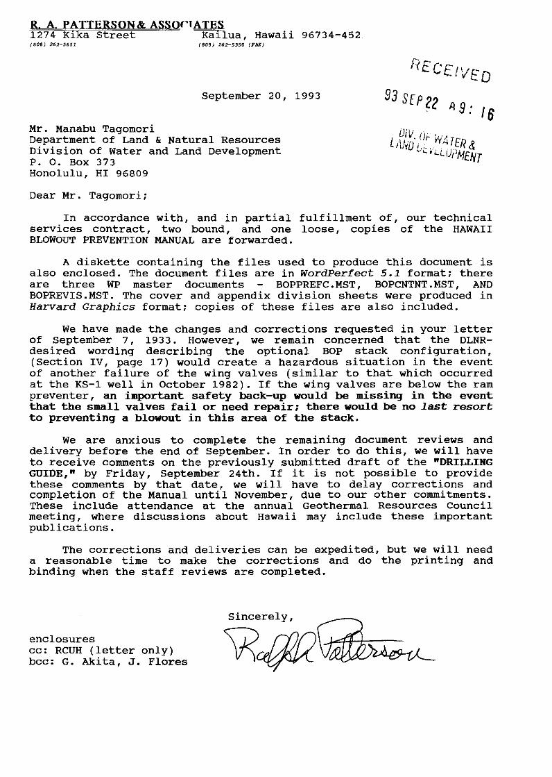
R A. PATTERSON& ASSQ('TATES 1274 Kika Street Ka~lua, Hawaii 96734-452 (808) 262-5651. (808) 262-5350 (FAX)
September 20, 1993
Mr. Manabu Tagomori Department of Land & Natural Resources Division of Water and Land Development P. o. Box 373 Honolulu, HI 96809
Dear Mr. Tagomori;
In accordance with, and in partial fulfillment of, our technical services contract, two bound, and one loose, copies of the HAWAII BLOWOUT PREVENTION MANUAL are forwarded.
A diskette containing the files used to produce this document is also enclosed. The document files are in WordPerfect 5.1 format; there are three WP master documents BOPPREFC.MST, BOPCNTNT.MST, AND BOPREVIS.MST. The cover and appendix division sheets were produced in Harvard Graphics format; copies of these files are also included.
We have made the changes and corrections requested in your letter of September 7 , 19 3 3. However, we remain concerned that the DLNRdesired wording describing the optional BOP stack configuration, (Section IV, page 17) would create a hazardous situation in the event of another failure of the wing valves (similar to that which occurred at the KS-1 well in October 1982). If the wing valves are below the ram preventer, an important safety back-up would be missing in the event that the small valves fail or need repair; there would be no last resort to preventing a blowout in this area of the stack.
We are anxious to complete the remaining document reviews and delivery before the end of September. In order to do this, we will have to receive comments on the previously submitted draft of the "DRILLING GUIDE," by Friday, September 24th. If it is not possible to provide these comments by that date, we will have to delay corrections and completion of the Manual until November, due to our other commitments. These include attendance at the annual Geothermal Resources Council meeting, where discussions about Hawaii may include these important publications.
The corrections and deliveries can be expedited, but we will need a reasonable time to make the corrections and do the printing and binding when the staff reviews are completed.
enclosures cc: RCUH (letter only) bee: G. Akita, J. Flores
Sincerely,

JOHN WAIHEE
GOVERNOR OF HAWAII
STATE OF HAWAII DEPARTMENT OF LAND AND NATURAL RESOURCES
DIVISION OF WATER AND LAND DEVELOPMENT
Mr. Ralph A. Patterson President R. A. Patterson & Associates 1274 Kika Street Kailua, HI 96734
Dear Mr. Patterson:
P. 0. BOX 373
HONOLULU. HAWAII 96809
July 27, 1993
Geothermal Blowout Prevention Manual and Drilling Guide
KEITH W. AHUE, Chairperson BOARD OF LAND AND NATURAL RESOURCES
DEPUTIES
JOHN P. KEPPELER, II DONA L. HANAIKE
AQUACULTURE DEVELOPMENT PROGRAM
AQUATIC RESOURCES CONSERVATION AND
ENVIRONMENTAL AFFAIRS CONSERVATION AND
RESOURCES ENFORCEMENT CONVEYANCES FORESTRY AND WILDLIFE HISTORIC PRESERVATION
LAND MANAGEMENT STATE PARKS WATER ANO LANO DEVELOPMENT
Thank you for the two bound copies and the original unbound copy of your "Hawaii Geothermal Blowout Prevention Manual". We will review the manual and provide you with our comments prior to printing and release to the public.
Submittal of two complete copies of the draft "Hawaii Geothermal Drilling Guide" is due on July 30, 1993. The final version of the drilling guide which is due on August 6, 1993, should include two bound copies and one original unbound copy. Also, copies of the Blowout Prevention Manual and Drilling Guide on disk in Wordperfect format should be submitted along with the final drilling guide.
Please note that according to the March 15, 1992 Agreement, you will be expected to present the Blowout Prevention Manual and Drilling Guide to our staff and to the Geotechnical Advisory Committee as your final tasks. The dates of these presentations will be scheduled after the submittal of the final Hawaii Geothermal Drilling Guide.
Should you have any questions on these matters, please contact Mr. Gordon Akita at 587-0227.
Sl cerely, ~-~
JF:ln
,IQHN WAIHEE
GOVHINOR OF H.O.WAII
Mr. Paul Stroud c/o Resource Group P.O. Box 1483
STATE OF HAWAII DEPARTMENT OF LAND AND NATURAL RESOURCES
DIVISION OF WATER AND LAND DEVELOPMENT
P. 0. AOX 373
HONOLULU. HAWAII 96809
AUG -5 1993
Healdsburg, California 95448
Dear Mr. Stroud:
KEITH W. AHUE, Chalrper~on
DEPUTifS
JOHN P. KEPPELER, II DONA L. HANAIKE
AQUACULTURE DEVfLOPMENT
PROGRAM
AQUATIC RESOURCES
CONSERVATION AND
ENVIrlONMENffo.l MFA!nS CONS(IWAlll•N MW
RESOURCES FNFOACEMENT
CONVfYANC"fS
f(lflf~;Jf\Y ANIJ Wlllllll!
HISTOFliC" rfl[SUWA T ION
LAND MANAGEMENT STATE PARKS
WATER AND LAND DEVELOPMENT
Thank you for your May 1993 letter conveying your comments on the draft of the Hawaii Geothermal Blowout Prevention Manual. Your participation in our external review process is appreciated and your comments will certainly be considered in frnalizing the document.
Should you have any questions regarding this matter, please contact Mr. Gordon Akita of the Flood Control and Mineral Resource Branch at (808) 587-0227.
JF:lc

JOHN WAIHEE
00\IHINOR OF HAWAII
Mr. Bill Rickard c/o Resource Group P.O. Box 1483
rt;:~ \·· STATE OF HAWAII
DEPARTMENT OF LAND AND NATURAL RESOURCES DIVISION OF WATER AND LAND DEVELOPMENT
P. 0. BOX 373
HONOLULU, HAWAII 96809
AUG -5 1993
Healdsburg, California 95448
Dear Mr. Rickard:
KEITH W. AHUE, Chairperson
flri,\IHl <H IIINI1 M"' "~''"''" "'
lJFI'U 11r S
JOHN p_ KFPPELER. II DONA L. H/\N/\IKF
AOUACULlllfiF rJFVLI OPMFtl I
PI10GRAM AQUATIC A!::SOURCFS
CONSERVAIION AND
ENVIRO~lMFNTAl MI'AifiS \.ONSERVIITI(\N Atl()
RfSOI!Rr;r:s FNI'lflr'IMfNI CONI/f)/IN( I.-,
ronrsrnY Mm WllllLIIr
HISTORIC PRESERVATION
LAND MANAG~MENT
STAlE PARKS
WATER AND lAND DEVELOPMENT
Thank you for your May 1993 letter conveying your comments on the draft of the Hawaii Geothermal Blowout Prevention Manual. Your participation in our external review process is appreciated and your comments will certainly be considered in fmalizing the document.
Should you have any questions regarding this matter, please contact Mr. Gordon Akita of the Flood Control and Mineral Resource Branch at (808) 587-0227.
JF:lc

JOHN WAIHEE
GOVERNOR OF HAWAH
STATE OF HAWAII DEPARTMENT OF LAND AND NATURAL RESOURCES
DIVISION OF WATER AND LAND DEVELOPMENT
Mr. Bill Teplow c/o Teplow Geologic 1901 Harrison Street, Suite 1590 Oakland, California 94612
Dear Mr. Teplow:
P. 0. BOX 373
HONOLULU, HAWAII 96809
JAN 2 5 1993
WILliAM W. PATY, CHAIRPERSON
BOARD OF tAitO AltO NATURAL RESOURCES
DEPUTIES
JOHN P. KEPPELER, II DONA L. HANAIKE
AQUACULTURE DEVELOPMENT PROGRAM
AQUATIC RESOURCES CONSERVATION AND
ENVIRONMENTAL AFFAIRS CONSERVATION AND
RESOURCES ENFORCEMENT CONVEYANCES FORESTRY AND WILDLIFE HISTORIC PRESERVATION
PROGRAM LAND MANAGEMENT STATE PARKS WATER AND LAND DEVELOPMENT
Thank you for your December 28, 1992 letter conveying your comments on the draft of the Hawaii Geothermal Blowout Prevention Manual. Your participation in our external review process is appreciated and your comments will certainly be considered in fmalizing the document.
Should you have any questions regarding this matter, please contact Mr. Gordon Akita of the Flood Control and Mineral Resource Branch at (808) 587-0227.
JF:lc
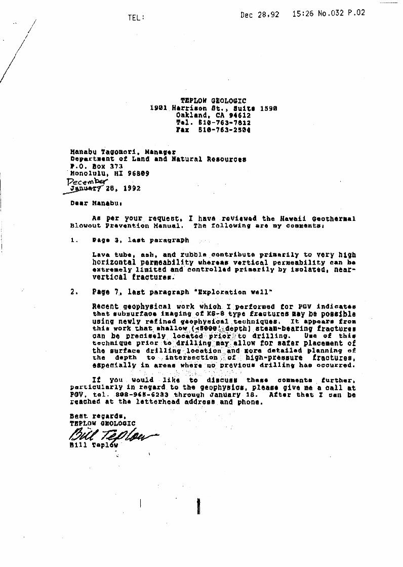
I I
TEL: Dec 28,92
'l'IIPLOif GllOLOG!C 19el Ha~ri•on St., su1~1 159e
Oakland, CA t4612 'l'el. £18-763•7&12 ra~ 818-7&3-2504
Manabu !avomori, Manater Departaen~ of Land and Ha~ural keeouroee r.o. !ox 373 Honolulu, HI 96889 'Peci!~ her' ~38, 19U
Dear Manabuo
15:26 No.032 P.02
As per your requeo~. I have rev:l.twecl the Hawaii Geotheraal Blowout Prevention Kanual. The rollowing are my coamentso
Lava tube, ash, and rubbla.contribute primarily to very h19h horizontal per11eabiHty wheru• vertical per111eab1l1t.y ~>an be extremely lim1ted and. controlled primarily by isolated, nearvertical fracturea.
2. Page 7,, last paragraph "Exploration well"
Recent geophysical work which I performed tor PGV inclicatee that eubsurtace ima;ino of xs-.a type f.ragtures may be possible using newly rafined 9eophy~ic~l techniques. It appear• froa thh work t.hat. ahallow ( ... seee!,.Jdepthl eteall•bearinq fractures can be preaisely locii'ted pdorrto drillino. Uee of th:l.• t:e.;hnique prlar to 4rUUnv.:mo.y, allow tor sat:ar place11ent of the surface drillin9 ·location &ius mora detailed plannin9 of ~:he depth to :Lnteuectton ;,; uf b19hMpreeeure fractures, &BJ)aaially in are~" whei:e no· ~:~revtoua dr:l.llint hae occurred.
If you would like to discuss these coamenta further, pert:icularly in rev~rd to tbe qeophysice, please qive me a call at PGV. tel. 808-965-6233 through January 18. After that l =•n be reached at the letterhead address and phone.
Deflt regards, T!IPLOW CUIOLOGIC
~'*-~~

JOHN WAIHEE
GOVERNOR OF HAWAII
STATE OF HAWAII DEPARTMENT OF LAND AND NATURAL RESOURCES
DIVISION OF WATER AND LAND DEVELOPMENT
Mr. Gene Anderson Division Superintendent Nabors Loffland Drilling Company P.O. Box 418 Bakersfield, California 93302
Dear Mr. Anderson:
P. 0. BOX 373
HONOLULU. HAWAII 96809
JAN 2 5 1993
WILLIAM W. PATY, CHAIRPERSON
BOARD OF LAND AND NATURAl RESOURCES
DEPUTIES
JOHN P. KEPPELER, II DONA L. HANAIKE
AQUACULTURE DEVELOPMENT PROGRAM
AQUATIC RESOURCES CONSERVATION AND
ENVIRONMENTAL AFFAIRS CONSERVATION AND
RESOURCES ENFORCEMENT CONVEYANCES FORESTRY AND WILDLIFE HISTORIC PRESERVATION
PROGRAM LAND MANAGEMENT STATE PARKS WATER AND LAND DEVELOPMENT
Thank you for your December 22, 1992 letter conveying your comments on the draft of the Hawaii Geothermal Blowout Prevention Manual. Your participation in our external review process is appreciated and your comments will certainly be considered in fmalizing the document.
Should you have any questions regarding this matter, please contact Mr. Gordon Akita of the Flood Control and Mineral Resource Branch at (808) 587-0227.
JF:lc

~~ l 1 ' l '
P.O. Box 418 NABORS LOFF'LAND DRILLING COMPANY Bokersfield, California 93302
3919 Rosedale Highway Bakersfield, California 93308 805-327-4695 805-327-4311 (Fax)
MR. MANABU TAGOMORI STATE OF HAWAII
December 22, 1992
DEPT. OF LAND AND NATURAL RESOURCES DIVISION OF WATER AND LAND DEVELOPMENT P.O. BOX373 HONOLULU, HAWAII 96809
Dear Mr. Tagomori:
~
:r-.- c: ;:~< o. c.---~
,-; ~~ ~
r :,_~ r l> c -< :.:rn 3.:::0 ~:>o -i
(!.)
"' = ,-.., CJ
. "' = D
= c.....J c.o
In reply to your request for comments on the draft of the "Hawaii Geothermal Blowout Prevention Manual", the following are my comments.
On Page 30, "Shut in Procedures" #2. WHILE TRIPPING should begin with:
a. Sound Alarm b. Lower drill string to place drill pipe tool joint just above the rotary table or if
drill collars are in preventers, lower drill collars until drill collar box is just above the rotary table.
c. Set slips (install D.C. clamp on D.C.'s) d. Install the full opening safety valve. e. Close the safety valve; close the annular preventer. f. Notify the company supervisor. g. Make up the kelly; open the safety valve. h. Record the drill pipe and annular pressure build up.
If you have any questions regarding my comments, please do not hesitate to contact me.
GA/sk
r Gene Anderson Division Superintendent
:x: Ill c; fil ~ --Pl 0

JOHN WAIHEE
GOVERNOR OF HAWAII
STATE OF HAWAII DEPARTMENT OF LAND AND NATURAL RESOURCES
DIVISION OF WATER AND LAND DEVELOPMENT
Mr. Pete Wygle
P. 0. BOX 373
HONOLULU. HAWAII 96809
JAI1 I 9 1993
Energy and Mineral Resources Engineer State of California Department of Conservation Division of Oil and Gas 1000 South Hill Road, Number 116 Ventura, California 93003-4458
Dear Mr. Wygle:
WILLIAM W. PATY, CHAIRPERSON
BOARD OF UlNO liND NATURAL R~SOURCES
OEPUfi~S
JOHN P. KEPPELEA, II DONA L. HANAIKE
AQUACULTURE DEVELOPMENT PROGRAM
AQUATIC RESOURCES CONSERVATION AND
ENVIRONMENTAL AFFAIRS CONSERVATION AND
RESOURCES ENFORCEMENT CONVEYANCES FORESTRY AND WILDLIFE HISTORIC PRESERVATION
PROGRAM LAND MANAGEMENT STATE PARKS WATER AND LAND DEVELOPMENT
Thank you for your December 10, 1992 letter conveying your comments on the draft of the Hawaii Geothermal Blowout Prevention Manual. Your participation in our external review process is appreciated and your comments will certainly be considered in finalizing the document.
Should you have any questions regarding this matter, please contact Mr. Gordon Akita of the Flood Control and Mineral Resource Branch at (808) 587-0227.
JF:lc

STATE OF CAL!FORIHA - RESOURCES AGENCY
DEPARTMENT OF CONSERVATJ ON DIVISION OF OIL AND GAS 1000 SOUTH HILL ROAD, NUMBER 116 VENTURA, CA 93003-4456 (805) 654-4761
Mr. Manabu Tagomori STATE OF HAllA I I DEPARTMENT OF LAND AND NATURAL RESOURCES Division of Water and Land Development PO Box 373 Honolulu, HI 96809
Dear Mr. Tagomori,
d[CL.I/EO
ILSON. Governor ...:1 L L L
December 10, 1992
I have received a copy of your geothermal BOP manual, and it looks like Herb Wheeler at al have done a very good job for you. However, Dick Thomas, our geothermal officer in Sacramento and one of the authors of the technical investigation report that resulted in your contracting for the manual, thinks that there are a few areas in which I may be able to provide information of possible use before your manual is finalized.
To introduce myself, I am the llygle of "Hallmark and \lygle" mentioned in the references section of your manual as having written the BOPE book for the State of California. I have taught at the MMS-approved, IIOGA/IADC well control school at Ventura College, so I can probably hold my own in a discussion of oil and gas well blowout prevention, but I will be the first to admit that my actual experience with geothermal blowouts is extremely limited. I will, therefore, make no effort to pass myself off as any sort of an "expert" in the field.
The references section of your manual cites the 2nd edition (1976) of Manual M07, but we are up to the 5th edition (1985) and are about to produce the 6th edition in which we intend to expand our efforts along the geothermal line.
I am enclosing a draft of the geothermal section of the 6th edition. This change contains our first effort to classify geothermal BOPE so that we can require equipment that is tailored to the situation presented by a specific drilling proposal. This gives us a little more latitude than that indicated in your proposed manual, which shows only a diverter system and a "Cadillac" system.
I'm a little bit concerned about the fact that your proposed manual doesn't make a bigger deal of the value of cold water in geothermal kick response. It is mentioned late in the first paragraph on page

CALIFORNIA DIVISION OF OIL AND GAS December 10, 1992 SUBJECT: Hawaii Geothermal Blowout Prevention Manual Page 2 of 2 Pages
22, but cold water always seems to be the first thing that is mentioned when I have asked people in the geothermal or steam injection business about their plans for kick control. It is not mentioned at all in the KICK KILL PROCEDURES section on page 31.
Also, I think you should consider outlining shut-in procedures to be followed when drill collars are in the preventers. This possibility is not mentioned among the choices in the SHUT IN PROCEDURES section on pages 30 and 31, but kicks taken at this critical point in pipe-pulling operations have caused some of the major blowouts in recent history.
My only other comment at the moment has to do with a consistent typograpl>ic error in the manual. In the term H,S, the "2" is consistently superscripted as a power instead of subscripted as a term in a chemical formula should be.
I hope I have reswonded as you asked in your cover letter that I should. If there is any other help I can provide, please call me at the phone number in the letterhead.
Regards,
~ Pete Wygle Energy and Mineral Resources Engineer

JOHN WAIHEE
GOVERNOR OF HAWAII
STATE OF HAWAII DEPARTMENT OF LAND AND NATURAL RESOURCES
DIVISION OF WATER AND LAND DEVELOPMENT
Mr. W.R. Craddick Senior Vice President Water Resources International, Inc. 2828 Paa Street, Suite 2085 Honolulu, Hawaii 96819
Dear Mr. Craddick:
P. 0. BOX 373
HONOLULU, HAWAII 96609
JAN I 9 1993
WILLIAM W. PATY, CHAIRPERSON
BOARD OF LANO AND NAlURAL RESOURCES
OEPUliES
JOHN P. KEPPELER, II DONA L. HANAIKE
AQUACULTURE DEVELOPMENT PROGRAM
AQUATIC RESOURCES
CONSERVATION AND ENVIRONMENTAL AFFAIRS
CONSERVATION AND RESOURCES ENFORCEMENT
CONVEYANCES FORESTRY AND WILDLIFE
HISTORIC PRESERVATION
PROGRAM lAND MANAGEMENT STATE PARKS
WATER AND LAND DEVELOPMENT
Thank you for your December 17, 1992 letter conveying your comments on the draft of the Hawaii Geothermal Blowout Prevention Manual. Your participation in our external review process is appreciated and your comments will certainly be considered in finalizing the document.
Should you have any questions regarding this matter, please contact Mr. Gordon Akita of the Flood Control and Mineral Resource Branch at (808) 587-0227.
UTA~~-.-----Chief Engineer
JF:lc
HAWAII GEOTHERMAL BLOWOUT PREVENTION MANUAL
DRAFT
State of Hawaii DEPARTMENT Of LAND AND NATURAL RE80URCE:5
Division Q! Water and Land Development

HAWAXX GEOTHERMAL BLOWOUT PREVENTXON MANUAL
State of Hawaii DEPARTMENT OF LAND AND NATURAL RESOURCES Division of Water and Land Development
Honolulu, Hawaii October 1992
• c

JOHN WAIHEE Governor
BOARD OF LAND AND NATURAL RESOURCES
WILLIAM M. PATY, Chairperson, Member at Large
SHARON R. HIMENO, Member-at-Large
JOHN Y. ARISUMI, Maui Member
CHRISTOPHER J. YUEN, Hawaii Member
HERBERT K. APAKA, Kauai Member
DEPAR'l'MER'I' OF LARD ARD NA'l'URAL RESOURCES
WILLIAM M. PATY, Chairperson and Member Board of Land and Natural Resources
DONA HONAIKE, Deputy
JOHN P. KEPPLER, Deputy

ACKNOWLEDGEMENT
This document was prepared by R. A. Patterson & Associates, Kailua, Hawaii. for the Hawaii Department of Land and llatural Resources under Contract Agreement No. RCUH P. o. 4361021. The work was performed by Ralph A. Patterson, William L. D'Olier, and Herbert E. Wheeler. We wish to gratefully acknowledge the assistance of the staff of the Division of Water and Land Development, under the direction of Manabu Tagamori, and of the invaluable suggestions and assistance of all those who discussed the project with us.
Development of this Manual would not have been possible without the willing cooperation of many managers, technicians and professionals in the geothermal industry, various laboratories and academic institutions, and in other areas where their knowledge was helpful in presenting the review and recommendations of the Manual. The authors wish to acknowledge their help and candor, and their accumulated knowledge that has made our job easier.

PREFACE
The prevention of an uncontrolled well flow, commonly known as a "blowout", is
of vital importance for geothermal operators, drilling crews, state and county
regulators, and the general public. Geothermal well blowouts have not been the cause
of a signilicant number of fatalities, and the danger of fire, as in petroleum drilling,
is quite low. However, blowout incidents may have a negative impact on surface and
subsurface environments, cause resource waste, and develop unfavorable public
perceptions of geothermal activity. These concerns are powerful incentives to
operators and regulators to minimize the risks of a blowout.
This Manual has been developed to promote safety and good resource
management by discussing and describing blowout prevention as it can best be
practiced in Hawaii.
The intent of this Manual is to provide the necessary information to guide
regulators and operators in the practices and procedures, appropriate to each drilling
situation, that will minimize the risks of a blowout. The Manual is also intended to
promote an informed flexibility in blowout prevention practices, and to supplement
State and County regulations, especially those pertaining directly to drilling permits
and operations,!
I
This first edition of the Blowout Prevention Manual is a likely candidate for
revision as ~re drilling experience and information is gathered in the exploration and
development of Hawaii's geothermal resources.
1 Department of Land and Natural Resources (DLNR) Title 13, Subtitle 7. Water and Land Development; Chapter 183.
BOPPUnC!/R!P /loftlber 5, 1992

SUM.M.ARY
A summary of the Hawaii Geothermal Blowout Prevention Manual
will be included in the final document.

CONTENTS
Acknowledgement
Preface
Summary
L. SCOPE
II. GEOTHERMAL DRILLING RISKS IN HAWAII
III. GEOTHERMAL WELL PLANNING.
IV. BLOWOUT PREVENTION STACKS AND EQUIPMENT
'L._ EQUIPMENT TESTING AND INSPECTION
VI. DRILLING MONITORING PROCEDURES
VII. KICK CONTROL
VIII. BLOWOUT CLASSIFICATION
IX. SUPERVISION AND TRAINING
x.,_ POST COMPLETION BLOWOUT PREVENTION
XI. BLOWOUT PREVENTION IN SLIM HOLES
APPENDICES
A - Procedures for Manual Review and Revisions
B - Illustrations
C - References
D- Glossary
BOPCOm/RAP/RI'I:Iol!lb!r 11, 1'192 i
Page
1
2
6
12
17
19
29
32
34
37
38

The material in this Manual has been extracted from many key information
sources in order to present a complete and accurate review of the practices of
geothermal well control in Hawaii. In developing this Manual, a careful review of
drilling to date in the Kilauea East Rift Zone (KERZ) was conducted. The KERZ is where
nearly all Hawaii geothermal drilling has taken place, and is where most experts believe
the geothermal resources will be developed.
The general belief in the industry is that each area is "unique", since each
prospective geothermal area throughout the world has proven to have its own
characteristics in terms of drilling conditions, resource chemistry, geology, etc. While
this may be true in detail, some similarities do exist among geothermal areas located
in, or nearby, active volcanic areas. Thus, it has been helpful to briefly review well
control techniques and experiences from other similar volcanic areas around the world.
Some of the information gathered may have an influence on geothermal drilling in
Hawaii.
In order to review the experiences in Hawaii and in other geothermal areas
where active volcanism is prevalent, a great number of specific publications and
selected references were consulted. These are listed in AppendD C, References. In
addition, much of the information and many recommendations contained in this Manual
came from the accumulated experience of others who were consulted on various
elements of the items presented. A partial list of those consulted is also contained in
AppendD C.
This Manual defines a blowout prevention strategy for geothermal drilling in tbe
state of Hawaii. The essential components of this strategy are:
1) Improved risk analysis and well planning:.
2) Sound select:iml of blowout prevention sblcks and associated equipment.
3) Rigorous use of drilling monitoring procedures.
4) Expertise in kick control and blowout prevention equipment utilisation.
5) Jl!xceJlence in supervision and training of drilling personnel.
1

II .. GEOTHERMAL DRILLING RISKS IN HAWAII
THE VOLCANIC DOMAIII
The State of Hawaii consists of a chain of volcanic islands. Each island is a
composite of several volcanic eruptive centers built up by a succession of basaltic lava
flows, first as submarine deposits and subsequently as volcanic lands (or subaerial
deposits.) These basaltic lava flows form a sequence of near horizontal layers
consisting of hard crystalline flow rocks intebedded with lesser amounts of highly
variable rock debris. These flow sequences are evident in extensive outcrops and in
lithology logs from water well drilling.
Recently recognized geothermal resources are characterized by relatively small
prospective areas which are strongly associated with active or recent volcanism. The
highest probability areas for geothermal development overlie the volcanic rift zones
which are, or recently were, deep conduits for magma transport away from the volcanic
eruptive center. Hawaiian geothermal drilling to date has been confined to the active
Kilauea East Rift Zone (KERZ). In the KERZ, the magma (1900°F and higher) and lava
processes provide very high subsurface temperatures. Large amounts of meteoric
water (groundwater) and seawater intrude into the KERZ geothermal resource zones,
providing an abundant fluid supply for heat transfer.
Geothermal drilling in Hawaiian rift zones involves distinctive risks. A reasonable
initial identification of hazards and risks is now possible due to KERZ drilling
experience, combined with extensive studies by the Hawaii Volcano Observatory (HVO)
of KERZ rift zone function, structure and dynamic processes. This experience and
knowledge can be used to refine geothermal drilling programs and procedures to
minimize the risks of upsets and blowouts.
IUm.Z DRILLIIIIG TO DATE
The most valuable subsurface information for this Blowout Prevention Manual
comes from 12 deep geothermal wells and three exploratory slimholes drilled in the
KERZ since 1975. Rotary drilling rigs appropriate to the drilling objectives were used
on the twelve geothermal wells. Common drilling fluids used in this rotary drilling
are mud, water, aerated fluids and air. The well depths range between 1,670 to 12,500
feet below the ground surface. The Operators for the well drilling included four
2

private resource companies and one public sector research unit.
As of 1992, nine wells had penetrated prospective high temperature rocks and
seven of these were flow tested or manifested high temperature fluids. The resource
discovery well, HGP-A, completed in mid-1976, provided steam to a 3MW demonstration
electrical generation plant between 1981 and 1990. Two of the nine wells incurred
casing contained blowouts in 1991 upon unexpectedly encountering high pressured
geothermal fluids at shallow depths.
Three deep scientific observation holes (SOH) were drilled for resource
evaluation as continuously cored exploratory slimholes to 5,500-6,800 foot depths in
1990 and 1991. These SOHs helped to prove that favorable high temperatures prevail
over a ten mile interval along the KERZ. These holes did not encounter subsurface
conditions that involved significant blowout risks; however, special blowout prevention
equipment must be considered for future use of the slimhole technology in Hawaii.
SUBSURFACE COifDI'l'IOifS Ilf PROSPECTIVE AREAS
High temperatures, commonly in the 600-7001T range, are characteristic of
production zones in the volcanically active rift zones. The prospective geothermal
reservoir occurs in the roof rock above the deeper magma conduits. The well
completion targets are loci of permeable, highly conductive fault and fracture zones
which are generally enclosed by extensive secondary mineralization. Magma transport
downrift and its planar injection upward into the roof rock are the primary heat
sources for the geothermal resource.
The primary hazard of geothermal drilling in the volcanically active KERZ
is the currently unpredictable distribution of fault planes and major fractures. The
walls of these geologic structures are commonly sealed by secondary mineralization;
thus creating conduits for geothermal fluids. These fault and fracture conduits, can
present pressures ia.tbn g d &00 t,' '750 1 si above normal hydrostatic pressure,
particularly as they extend upward into cooler ground water regions. Unexpected
entry into such over pressured fault planes and fractures can cause substantial
upsets to all well control procedures.
Primary features such as lava tubes, irregular layers of ash and rubble, and
fractures contribute to very high vertical permeability, which can pose a problem
with loss of drilling fluid circulation to fluids and to low rock strengths. These
3

primary features seem to diminish down ward, but appear to extend to depths of 2000
feet.
An important feature of the KERZ is the seaward slip-faulting of its
southeastern flank caused by cross rift extensional stress. This seaward sliding of the
roof rock, coupled with seismicity, results in molten dike intrusions and fracturing.
Dike intrusions allow an abundant supply of heating and creates prospective
fracturing for the geothermal reservoir. All these features further contribute to low
rock strengths in the shallow near surface volcanics, which can be a problem when
attempting to locate a sound anchor for wellhead blowout prevention equipment.
The geohydrology of the KERZ involves large volumes of groundwater and
seawater. The relatively cool groundwater body, located just above sea level is
maintained by high annual rainfall and a high rate of infiltration. The KERZ geothermal
fluid system may be fed by a major groundwater basin on Mauna Loa's eastern flank.
Large volumes of seawater have the potential to penetrate the geothermal reservoir
through fractures at depth. Earthquakes in the region may cause existing fractures
to widen or may create new fractures. An increase in the salinity of the fluids
produced by the HGP-A well may have been caused by earthquake induced fractures.
Hydrostatic pressures are indicated to prevail in active rift zones, but these can be
escalated to higher fluid pressures in the temperature conditions prevailing. The
fresh and saline groundwater body, shown to prevail as deep as 2,500 feet in the Puna
geothermal field, may prove to be a general condition, but not one that can be
expected at every proposed well location.
SUMMARY ,
The Kj!!RZ geothermal drilling experiences prove two significant hazards that
must be addressed in a blowout prevention strategy for every proposed well:
1. Significant fault and fracture planes can be sealed conduits for
overpressured geothermal fluids. These features might eventually prove
to be predictable or detectable by drilling precursors. Blowout
prevention planning, equipments and procedures must be taken as a
critical requirement, ready for immediate and proficient use.
2. Weak and broken near surface volcanic rocks. The recognition of this
condition is a precursor to obtaininga reliable casing anchor, which is }\
4 'I

fundamental to safe blowout prevention by complete shut off. .
5

III. GEOTHERMAL WELL PLANNING
INTRODUCTION
The proven higher costs and uncertainties in Hawaiian geothermal drilling
operations are sound reasons to make an extraordinary investment in well planning.
Detailed planning is a must for each and every type of well because of the paucity of
subsurface information and the small base of drilling experience to date. Blowout
prevention is an integral element of geothermal well planning.
WELL PLAMIIDIG OBJEC'l'IVES
Safety The concept of safety must be carefully applied for all workers and
activities at the wellsite and for the public. A blowout prevention strategy is a crucial
part of any successful practice of safety in geothermal drilling; it is a necessity in
Hawaii.
Well PunctiDn Geothermal wells, if beneficial development is to be attained, must
convey and control very large quantities of fluid and energy, hopefully for the
greater part of the 30-year life that is expected in electric power systems. The HGP-A
discovery well demonstrated a reasonable performance in the production mode from
1983 to 1990.
Reasonable Cost Hawaiian geothermal wells are in the very costly category;
perhaps $2,500,000 per well is a representative minimal cost (1992$} if no significant
problems impact a good drilling plan. Competent planning might cost only 1 or 2\ of
the total cost of a successful well.
High quality well planning will assure a greater degree of safety and improved
well functions. Proper well planning will allow the Operator to be more confident in
responding to the upset conditions that can't be avoided and actual drilling
performance can be better assessed for continued improvements in future Hawaiian
geothermal wells.
DRILLIBG TARGETS AlfD WELL 'l'YPES
6
Geothermal drilling targets in the volcanic realm of Hawaii can be organized into
three simple classifications:
Explorat:im:l targets - to discover the resource, are generally identified by a
favorable combination of subsurface data indicating heat, fluids and fractures
(voids). Targets that can win drilling funds, but which present a high risk
exposure, are classified as exploratory by the Operator and participants.
Res t voir targets - to develop the resource, are generally qualified by high
temperatures, indicated fault planes and fracture systems or by nearby well
production data. The probability of penetrating both high temperatures and
fluid producing permeability intervals is high. Hawaiian geothermal reservoirs
are of the hydrothermal type {the predominate type now in worldwide
utilization.)
Supplemental targets - to conduct research on the resource, are comprised of
scientific and/or observational objectives which can contribute to a better
understanding of a geothermal resource and its enclosing subsurface
environment.
At the present level of knowledge in Hawaiian rift zones, no class of geothermal
drilling target can be confidently identified with lower blowout risks. Off rift
geothermal drilling targets may offer the perception of lower drilling risks, however,
no such drilling has been undertaken as of 1992.
Geothermal wells can be categorized as to function and several additional
features. The common types of wells include the following:
Expkral:ion well. Any well drilled to evaluate a prospective geothermal resource
target, usually at some sigrrifi.cant distance from an established or proven
geothermal reservoir. Hard and proximal subsurface data are not likely to be
available for a blowout prevention plan; diligent drilling monitoring procedures
(see Section VII) and casing plan flexibility are essential to blowout risk
reduction in exploration wells.
Production welL Any well designed to exploit the energy and fluids of a
BOPPWIIJC/IILD/Ioftllber lL 1992 7

geothermal reservoir for beneficial use or demonstration purpose. Blowout
prevention plans for production wells can be better specified to more
confidently known subsurface conditions.
Injecl::ion well. Any well designed to return the geothermal effluent to the
reservoir or other deep disposal zones. Injection wells will have blowout
prevention requirements similar to nearby production wells.
Slimhale. This type of geothermal well is identified by its small diameter
borehole, 6 to 4 inches, compared to the 17 t - 8 t inch hole diameter range
commonly used worldwide in the geothermal industry. The slimhole technology,
presently surging in evaluation and use in the petroleum industry, has a
distinct blowout risk and prevention requirement. The technology has been
safely introduced in the KERZ when HNEI accomplished three continuous
boreholes between 5500 and 6000 foot total depths in its Scientific Observation
Hole Program (1989-91). Discussion of the blowout prevention in slimholes is
presented in Section XII.
Deep versus shallow wells. These are terms of convenience in their general
usage; however, regulations may impose a legal definition on them. A historical
point of interest in the KERZ should be noted; several early geothermal
exploration holes, drilled safely with cable tools, encountered near boiling waters
at very shallow depths next to recent lava flow fissures and vents. Depth seems
to have no correlation with blowout risk in Hawaii's geothermal drilling to date.
However, it should be evident that relatively shallow blowouts in the porous
surface lava rocks and large fissures, broadly prevailing in Hawaii, could be
particularly difficult to kill.
Vertical versus deviated wells. It appears that Hawaiian geothermal wellfi.elds will
be extensively developed with deviated wellbores. Blowout prevention
requirements are not altered in any type of geothermal well by the vertical or
deviated course of its wellbore.
THE DRILLING PLAR
8
Every geothermal well proposed for funding and permitting will rl!quire a
drilling plan. Regardless of the geothermal well type, the drilling plan is the specific
technical document that should reflect the best thinking on how the well can be safely
constructed and its function obtained at reasonable cost. Safety is considered on a
broad front in a carefully prepared drilling plan. Commonly the deliberate actions to
optimize safety in geothermal drilling will be specified or reflected in four distinct
sections of the drilling plan, as follows:
1. Casing and cement. The intended function of the proposed well will be
a factor in casing design and cementing procedures selected. However,
the best available subsurface data sets on geology, hydrology, pressure
and temperature profiles, form~tion failure thresholds (fracture gradient),
together with the wellsite elevation, comprise the basis for increased
safety in drilling and quality of construction. The subsurface conditions
and well sire elevation are unique to each intended wellbore; the proposed
casing and cement plan must reflect a reasonable response to these
conditions. KERZ drilling experience reveals several special concerns for
blowout prevention.
' \·J
a. A preference to cement the surface casing (commonly 20 inch
diameter) below the water table can be acknowledged. Where the
groundwater table is within 600-800 feet below the surface, an
approximate 1,000 foot length of surface casing would meet this
objective. Where the groundwater table is much deeper, it could
be difficult to obtain a good cement sheath on surface casing set
at, say 1,700 feet, because of the presence of lost circulation zones
and incompetent rock in which to cement the casing shoe. Prudence
suggests that it is better to obtain a quality cement sheath on a
shorter length of surface casing.
1', ;·
(\ i ,. \, (} r·
----..; ' 'i\
{· \
' \
\
BOPPLAIIIIC/iLD/Io"* 11, 1!92
b. Independent of the quality of cement sheath obtained on surface
casing, the possibilities of fractures, other permeable paths to the
surface and low formation fracture gradients exist in the near
surface volcanic rocks penetrated by the surface casing. This
points to a serious risk in using a complete shut off (CSO) blowout
prevention system on the surface casing while drilling to the
intermediate casing depth. A CSO could force unexpected hot and
9

/
possibly pressured formation fluids to an external blowout (outside
the surface casing and cellar). External venting of this type can
pose more complex and precarious kill operations, and also threaten
the drilling rig's ground support. Accordingly, a diverting capacity
and large diameter flow line from the wellhead to a distant disposal
point is to be considered. This approach would contain such an
uncontrolled flow inside the surface casing and afford a safer kill
procedure confined to the wellbore.
c. Intermediate casing {commonly 13-3/8 inch diameter) may be set
at depths between 1,000,-2,500 feet below the surface casing shoe
if no unexpected geothermal fluids or anomalies are encountered.
The intermediate casing shoe depth should optimally be below the
major groundwater body. It should also be below extensive
fracturing that may reach up to the groundwater table, frequent
occurrence of lost circulation zones, and less competent volcanic
rock. Because the intermediate casing becomes the anchor casing
for the complete BOP equipment stack required to drill to total
depth, it is critical that the cement sheath in the open hole (17 ! inch diameter) annulus be of the highest possible quality. The
findings in the 17 ! inch drilled hole should be carefully studied.
Any adverse downhole conditions can be mitigated by cementing the
bottom portion of the intermediate casing as a liner in the open hole
interval (lapped several hundred feet into the bottom of surface
casing). The upper portion can be run and cemented as a tie back
I string inside the surface casing. Each of the two cement jobs
required should be of enhanced quality, should offset the external
natural hazards and should optimize the anchor for the complete
BOP equipment stack with its multiple CSO capacity over a full
range of drilling fluids.
2. Drilling fluids. The subsurface conditions encountered within the KERZ
are prompting the use of many drilling fluids ranging from moderate to
low density muds, water, aerated muds and water, to foam, and air.
Additionally, the ability to switch drilling fluids promptly is being
BOPPWIIIG/WLD/IoMb!r 11, 1.992 10

recognized as a cost effective advantage in greater well cont:.:-ol,. This
practice demands the use of BOP equipment compatible with a broad range
of drilling fluid options in a single wellbore. The diversity and flexibility
of drilling fluid utilization in Hawaii is encouraging, not only because all
fluids can be controlled by available BOP equipment, but because this
approach should lead directly to advanced safety margins, reduced
drilling times and lower costs. Drilling fluids and geothermal well control
are further discussed in Section VII.
3. Drilling Monitoring. This activity is usually integrated in thorough
drilling plans at many points. It is, however, quite important and
deserves more recognition as an effective method to reduce blowout risks.
A detailed consideration of drilling monitoring procedures is presented
in Section VII.
4. Blowout PreventiQn. Drilling plans may contain minimal specific
discussion of blowout preventiQn; a graphic sketch of the proposed BOP
equipment stack may be the lone obvious recognition of the subject.
However, a competent drilling plan will reflect, in its detailed provisions,
an Operator's blowout preventiQn strategy. The implementatiQn of risk
reduction will be evident in the casing, cementing and drilling fluid
provisions, in the drilling monitoring procedures, in proper training, and
finally in the BOP stack and its supplemental equipment. The drilling plan
should reveal the Operator's awareness that a blowout gm, happen, and
reflect the drilling supervisor's responsible determination that it has
been given the least possible chance to occur in the proposed well.
Blowout prevention is every Operator's final responsibility; it is achieved
first in the thinking and actions of all drillsite personnel through
training, by the practice of sound procedures, and by the use of reliable,
proper equipment.
BOPPLUIIIG/1LD/Ioftlb!r 11, 1m 11

IV- BLOWOUT PREVENTION STACKS AND EQUIPMENT
INTRODUCTION
Haw ali's geothermal drilling industry, still in a formative stage, has gained
sufficient experience and information to provide reasonable guidance to the
identification of more reliable and safer blowout prevention stacks and equipment. The
blowout prevention stack on the wellhead, when all other well control procedures have
failed, must function reliably to obtain a complete closure or effective control of
unexpected fluid flows from the wellbore. Blowout prevention stacks and related
equipment are not simple systems; they rely on integrated mechanical, hydraulic and
electrical processes to operate. Both redundancy and sophistication exist; however, the
risks of human error in critical situations have not been eliminated. Blowout
prevention systems require careful selection, maintenance, and repetitive training
of drilling crews to attain the reliability and safety which are essential in the final
defense against an actual blowout.
BOP DEFIIfiTIONS AlfD FUNCTIONS
1. Definitions
• The term blowout prevention equipment (BOP) here means the entire array
of equipment installed at the well to control kicks and prevent blowouts. It includes
the BOP stack, its activating system, kill and choke lines and manifolds, kelly cocks,
safety valves and all auxiliary equipment and monitoring devices. (see Glossary in
Appendix D for these terms).
• The BOP stack. as used here, is that combination of preventers, spools,
valves, and other equipment attached to the wellhead while drilling.
• A diverter stack is a BOP stack that includes an annular preventer, with a
vent line beneath. A valve is installed in the vent line so that the valve is open
whenever the annular preventer is closed, thus avoiding a complete shut off (CSO),
and diverting the flow of fluids away from the rig and personnel.
A full BOP stack is an array of preventers, spools, valves, and other equipment
attached to the wellhead such that complete shut off (CSO) is possible under all
conditions.
BOPS'!AaliUQUIP/IIEII/IILD/loftlahlr 11, 19!2 12

2. Functions
The main function of the BOP equipment is to safely control the flow of fluids
at the surface, either by diversion or by complete shut off. The equipment must be
adequate to handle a range of fluid types, pressures, and temperatures, and to
accommodate different drilling situations such as active drilling and tripping, or out
of the hole. The requirements of the BOP stack are to:
a. Close the top of the wellbore to prevent the release of fluids, or, to safely
divert the fluids away from the rig and personnel.
b. Allow safe, controlled release of shut in, pressured fluids through the choke
lines and manifold.
c. Allow pumping of fluids (usually mud or water) into the wellbore through kill
lines.
d. Allow vertical movement of the drill pipe without release of fluids.
Selection of BOP stacks and equipment should be made jointly by an experienced
geothermal drilling engineer and drilling supervisor. It is preferable to employ a
:.!supervisor
conditions.
that is experienced in Hawaii geothermal drilling experiences and ~H-('J ("\\c.<-
THE BOP AKCHOR
Complete shut off capability with a BOP stack requires the existence of a BOP
anchor. Three key factors are required for a sound BOP anchor:
1. A mechanically sound, continuous steel casing of reasonable length, which
probably will be 1000 feet or more, attached to the BOP stack.
2. A continuous and solid cement sheath in the annulus between the casing and
the rock wall of the wellbore.
3. An impermeable rock interval around the wellbore and cement sheath. The
entire section of rock need not be impermeable but priority is given to placing
and cementing the casing shoe in a thick interval of competent and impermeable
rock.
13

· IMPAC'I'S OF SUBSURFACE RISKS
Hawaii geothermal drilling has inherent risks due to the unpredictability of
subsurface conditions. Recognizing the risks and being prepared for all possible
conditions is the best form of blowout prevention. Subsurface conditions that may pose
the risk of a well blowout are listed below:
1. The almost certain inability to obtain a sound BOP anchor with surface casing
in the weak, often broken, and vertically permeable near surface volcanic rocks. As
discussed in Section n, if a "kick" occurs, these shallow rocks will not allow a CSO at
the wellhead without posing a significant risk of creating an externally vented well
casing blowout. (For discussion of externally vented blowouts, see Section vn.}
2. The unexpected entry while drilling into a major fault and fracture conduit
which is charged wfth overpressured geothermal fluids. Termination and control of
such events requires the certainty of a wellhead CSO with a full capacity BOP stack. l
The risk factors cited above reveal the importance of knowing when a BOP
anchor and consequent CSO capacity are available to prevent a blowout. If they are
not available, diversion of uncontrolled flows is judged to be the more prudent
response. On these fundamenW considerations, two basic BOP stacks are recommended
for Hawaii geothermal wells which are drilled with rotary rigs for exploration,
production or injection purposes.
BOP STACK RECOMMERDATIOI!IS
1. Diverter Stack (Figure !-Appendix B)
A diverter consisting of an annular preventer and a vent line should be
installed on the surface casing. In Hawaii, this casing is typically 20 inches in
diameter and is cemented in the 800 - 1,100 foot depth range. Incompetent near
surface volcanic rock and the high risk of cementing failure will not provide an
adequate BOP anchor. CSO is not intended with this equipment; diversion of
l In the KERZ, sudden geothermal fluid flows, which subsequently registered 500 to 700 psi shut-in wellhead pressures, were encountered at depths shallower than expected; in one case as shallow as 1,400 feet.
14

fluids is deliberate to avoid creating externally vented blowouts; ~nd for
personnel and rig safety.
2. Full BOP Stack (Figure 2)
A full BOP stack should be installed on the intermediate casing. In Hawaii, this
casing is typically 13-3/8 inches in diameter, and is cemented in the 2,000 -
3,500 foot depth range. This deeper casing, cement sheath, and host rock serves
~sa BOP anchor. The selection and arrangement of this stack allows for the use
' of a full range of drilling fluids (mud, water, aerated fluid, foam, air) and should
be a geothermal industry premium stack that is capable of confident, immediate
CSO over the range of temperatures and pressures anticipated. If a sufficient
BOP anchor is not obtained, this stack also has diverter capacity because of the
~/) - flo( -~T"(ve~t .. ·line, or, ban:!? box/blooi.e line, inc.luded ilJ th .. /'.·;R:ack. '~. ~ / -<'-A"· t:l. , '"" '·· •/. /· ,. "/.•· __ x.__/~'.,1-t;.<.h--'\)_L-<1
ADDITIONit RECOMMEifDA'l'IOBS I\ _.!. "/ c...- _{(_, .'/ r.J' -(~, .'~tCJJ• Jc .. , /) ) J ·!7' ('' f-. "' ' / ' . ' J' {-.4 , • j'' j-7·~. fi 1., D~ve~~. stack. ~Jh:" ~ve~~ ~c; sh:~~· haJ .,,~~- j~~:':U:~
characteristics: ..
A minimum pressure rating of 2,000 psi for all components.
b. Minimum vent line diameter of 12 inches.
c. A full opening valve on the vent line that opens automatically
when the annular preventer is closed; OR a 150 psi rupture
disk and a normally open valve.
d. The vent line directed through a muffler.
e. H2s abatement capability connected to the vent line.
2. Full BOP stack. The Full BOP stack should have the following
characteristics:
a. A minimum pressure rating of 3,000 psi for all components.
A pressure rating of 5,000 psi is recommended when indicated
by the risk analysis of the well. For temperature impacts on
pressure ratinqs, (See Fiqure 3)
b. Lower spool outlets - 2 inch diameter for a kill line and 4
inches for a choke line.
15

c. The pressure ratings for the kill and choke lines the same
as the stack.
d. All preventers should have high temperature rated ram
rubbers and packing units.
BOP EQUIPMENT RECOMMENDATIONS
1. Kill Line. 2 inch diameter kill line from pumps to spool. Two full
opening valves and one check valve at the spool. Fittings for an auxiliary
pump connection; pressure rating for the kill line the same as the stack.
The kill line is not to be used as a fill up line.
2. Choke Line and Choke Manifold. 4 inch choke line and manifold;
pressure rating the same as the stack. Two full opening gate valves next
to the spool; one of these valves remotely operated.
3. Actuating system. The actuating system should have an accumulator
that can perform all of the following after its power is shut off:
a. Close and open one ram preventer.
b. Close the annular preventer on the smallest drill pipe used.
c. Open a hydraulic valve on the choke line, if used.
The actuating system is to be located at least 50 feet from the well, with
two control stations -one at the drillers station on the rig and one at the /
· actuating system location.
I 4. other equipment. During drilling the following miscellaneous BOP
equipment is to be provided:
a. Opper and lower kelly cocks and a standpipe valve.
~b. A full opening safety valve, to fit any pipe in the hole. Kept
)
Lc. d.
on the rig floor.
An internal preventer, kept on the rig floor, with fittings to
adapt it to the safety valve.
Accurate pressure gauges on the stand pipe, choke manifold,
and other suitable places that may see wellbore pressure.
e. All flow lines and valves rated for high temperature service.
BOPS'!AClSUQUIP/IIIIf/ILD/Io'Mblr lL 1992 16

V. EQUIPMENT TESTING P~ND IN .SJ?ECTION
In general, a visual inspection and an initial pressure test should be made on
all BOP equipment when it is installed, before drilling out any casing plugs. The BOP
stack (preventers and spools, choke and kill lines, all valves and kelly cocks) should
be tested in the direction of blowout flow. In addition to the initial pressure and
operational test at time of installation, periodic operating tests should be made.
Pressure tests should subject the BOP stack to a minimum of 125% of the
maximum predicted surface pressure. If the casing is tested at the same time then
the test should not be more than 80\ of minimum internal yield of the casing at the
shoe. If a test plug is used, the full working pressure of the BOP stack can be tested;
a casing test would be made separately. Testing of the actuating system should
include tests to determine that:
1) The accumulator is fully charged to its rated working pressure;
2) The level of fluid is at the prescribed level for that particular unit;
3) Every valve is in good operating condition;
4) The unit itself is located properly with respect to the well;
5) The capacity of the accumulator is adequate to perform all necessary
functions including any kick control functions such as hydraulic valves
that are using the same unit for energy;
6) The accumulator pumps function properly;
7) The power supply to the accumulator pump motor will not be interrupted
during normal operations;
B) There is an adequate independent backup system that is ready to operate
properly; and
9) The control manifold is at least 50 feet from the well and a remote panel
is located at the driller's station.
10) All control valves are operating easily and properly, have unobstructed
access and easily identifiable controls.
The sequence of events to test the BOP stack and all other valves depends on
the stack configuration, but it is important that all equipment is tested, including the
annular preventer, pipe rams, CSO rams, upper and lower kelly cocks, safety valves,
internal preventers, standpipe valve, kill line, choke manifold and choke control valve,
17
internal preventers, standpipe valve, kill line, choke manifold and choke control valve,
pressure gauges, and any other items that are installed as part of the BOP equipment.
In addition to the initial testing of BOP equipment when it is first installed,
there should be frequent BOP testing and drills. The closing system should be
checked on each trip in or out of the hole and BOP drills should be held at least once
a week for each crew. It is most important that every member of the crew be familiar
with all aspects of the operation of the BOP equipment, along with all of the
accessories and monitoring devices that aid in detection of a kick. The main purpose
of drills is to train the crew to detect a kick and close the well in quickly. BOP drills
should cover all situations, while drilling, tripping, and with the drill string out of the
hole.
BOP'!!STIIC\B!II\WLD\Imlher U. 1!92 18

VI. DRILLING MONITORING PROCEDURES
INTRODUCTION
Operators commonly provide for some level of monitoring in the drilling of most
geothermal wells. All types of monitoring procedures will incur additional costs, which
may limit the selection of specific procedures. However, most Operators determine the
specific procedures in the context of what is known and not known about the
subsurface environment to be penetrated by the wellbore. This discussion of
monitoring will use the broad sense of the term, including mud logging.
Monitoring procedures may be defined as an array of continuous sensing actions
which attempt to accurately indicate subsurface conditions as the drill bit is advancing
through the rock formation.
MONITORING RATIONALE
Geothermal wells, drilled within the prospective, active volcanic rift zones of
Hawaii, merit carefully planned and integrated monitoring procedures. This view is
supported by two primary concerns. First, the subsurface geology, hydrology,
temperatures and pressures in the rock roof above the deep magma conduits, which
create the rift zone, are only partially known. Only 14 deep geothermal bores (11
wells and three scientific observation holes) have provided hard, factual subsurface
data as of mid-1992. Secondly, two geothermal wells have demonstrated that fault or
fracture conduits, charged with high pressure, high temperature fluids can extend
upward to relatively shallow depths from a deeper subsurface domain of >600°F
temperatures. These near vertical and planar conduits present both blowout risks
and significant geothermal energy production potential. This recent finding, proven
by drilling, has major implications. Geothermal drilling requires the evaluation and
more effective utilization of monitoring procedures as a supplemental strategy for
blowout prevention.
VITAL SECTORS
Monitoring focuses on three vital sectors during the drilling of a geothermal
well:
BOPMOilliJRIJG/iLD/IoMber 11, 1992 19

1. Drilling penetration rate and drill bit performance measurements. The
penetration rate, commonly measured and recorded in feet per hour,
indicates the mechanical progress of drilling in the host rock. Weight
on bit, rotational speed and torque are additional measurements that are
made to better understand the variations of the drilling penetration rate.
2. Drilling fluid circulation in the wellbore which clears the newly made hole
of drilled rock debris, cools and lubricates the rotating bit, and drilling
string. Importantly, the density and hydrostatic pressure gradient of the
drilling fluid are commonly used to control the formation fluids and
pressures encountered.
3. Physical conditions and resource potential of the newly penetrated rock
formation. The array of information gathered in this sector is commonly
presented in a continuous "mud log" graphic record over the entire
interval drilled.
The information products from the sectors discussed above have important
potential applications. Possible immediate improvements might be indicated in drilling
procedures, drilling fluid properties or casing plan in the well itself. Enhancements
in well design, drilling programs and/or cost reductions can be determined for future
wells. The information products of monitoring procedures, with careful integration and
evaluation, can make important contributions to an Operator's strategy of blowout
prevention.
OPTIMIZING BLOWOUT PREVEKTIOR
Any effective reduction in blowout risks is primarily contingent upon accurate
interpretation of monitoring data and ultimately depends on the decisions made, based
on this data. This must be achieved by the Operator. Having made the risk analysis,
written the drilling plan and obtained the funding for the well, the Operator's
geologist and drilling engineer presumably would be the most qualified persons to
establish the method by which the selected monitoring procedures would be used to
contribute to a blowout prevention plan. In prospective Hawaiian rift zones, the
prudent Operator, making careful use of monitoring information, can better identify
the potential for hot and overpressured fault and fracture conduits, and can better
prepare for penetration of such conduits and reduce impacts of ki.cks and lost
BOl'l«<lmJG/iLD/belh!lll,l9!2 20

circulation. Alternatively, a decision on whether or not to set casing can ·be. made,
particularly if a long open hole section is exposed above the interval of concern.
Critical data that may reveal the degree and/or immediacy of a blowout risk
. /~rfo ,Jtre probably first observed by key personnel of the drilling and mud logging
fV.r/ . . \{"I contractors. Exercising personal control of drill bit performance in making hole,
'Q ;:{' • r. '( drillers are the first to sense change at the bottom of the wellbore. Additionally,
A \r }\- / drillers must have an accurate, real time knowledge of the drilling fluid upflow in the
fr:· \' 1\/ annulus between drill pipe and the wall of the open hole. Gain or loss departures from
~~ ,,· r' l010~~ of t_he .drilling fluid pumped dow~ the drill pipe and t~rou~h the b~t orifi~es are f ,1\ , · . critical mdicators that, alone or w1th other corroborating mformation, s1gnal a
r' ,., (' ~'disruption of a normal drilling mode. ' ·\ ' -• (' 1 . ./ f
f' ('' '• 1 The mud logger and a supporting multiple sensor system continuously survey !' the changing rock features, formation fluids and temperature variations reflected in
the returning drilling fluid. This work is both time critical and time short because it
focuses evaluation on the narrow window of freshly exposed hole behind the
continuously advancing drill bit. Accordingly, good quality, competitive mud logging
has become a highly automated, computer assisted service with an impressive
reliability. The mud logger is the first to evaluate the formation gas and liquid
entries, via the returning drilling fluid, that may signal the penetration of high
temperature, high pressure conditions.
Operators of Hawaiian geothermal drilling projects need to assure that a high
level of cooperation in comprehending the norm and the upset hole conditions are
mutually practiced by their contracted drillers and mud loggers. The Operator's
drilling engineer and geologist should establish and maintain active communications
with these key specialists throughout the drilling process. It is essential that drillers
and mud loggers have reliable, instantly available electrical communication between
their work stations if monitoring procedures are to more effectively contribute to the
reduction of blowout risks. These simple procedures are intended to eliminate a
common problem: too often a key piece of new information is received, but is not
properly read, understood or communicated. Operators must lead their drillers and
loggers to consistent cooperation in monitoring procedures as an important protection
against the loss of well control. Inadequate responses to new well monitoring
information must be minimized in Hawaiian geothermal drilling.
BOPMOIITORIIG/WLD/Io9elber 11, 1m 21

. DRILLING FLUIDS AND GEOTHERMAL WELL CONTROL
All authoritative publications on blowout prevention {which to date exclusively
address oil and gas drilling) stress the role of drilling fluids in minimizing, if not
precluding, entries of normal or high pressured formation fluids into the wellbore
during the active drilling process. This is achieved by circulating a weighted mud or
salt water drilling fluid which creates an excess or overbalance of internal hydrostatic
pressure on every square inch of the open wellbore. The normal hydrostatic pressure
gradient for the formation fluids in Hawati rift zones should approximate 433 psi per
1,000 feet of vertical depth for fresh water and 442 psi per 1,000 feet for salt water.
This range of pressure gradients may prevail over much of the KERZ in the deep
geothermal zones because several geothermal wells were drilled through 2,500 foot
intervals of hot {600-700°F) prospective rock interval by circulating fresh water as a
wholly satisfactory drilling fluid. Well control was maintained confidently in these
operations and subsequently these fresh water drilled intervals yielded proven
geothermal fluids during flow tests following well completion. It should be noted that
the greater cooling capacity of water, as compared with mud drilling fluids, played a
positive role in these achievements.
Cooling by the circulation of drilling fluid is an inherent physical process in
geothermal well drilling. Where accelerated or optimized, the cooling process itself can
be recognized as a well control function. The efficient cooling of circulating drilling
fluids particularly will require an adequate surface cooling facility in the loop. Mud
cooling towers which allow the hot returning mud to fall in a baffle system against a
cool air draft are a standard equipment option for geothermal drilling. It is important
that mud QOOling towers be adequate for the heat load anticipated and that they be
carefully m;Lintained and monitored during use to assure that cooling is being
effectively' accomplished. Additionally, geothermal well control in Hawatian rift zones
requires ready access to an ample supply of cool water for wellbore circulation as a
well control option.
Both the specific KERZ drilling experience and the practice of world wide
geothermal drilling demonstrate the disinclination to drill with heavily weighted muds
or saline solutions as a preferred means of well control. This relates to the
expectation of finding fractures in the prospective hot zones which have much higher
permeability and production potential than a bulk rock interval of some uniform
primary (commonly lower) permeability. Fractures present the immediate risk of lost
BOPIIOmomc/llLD/Imlber 11, 1992 22

circulation and a possible well kick, particularly when overpressured fracture fluids . '
are released. The perceived benefits of significantly weighted drilling fluids
(significant overbalance - where the hydrostatic head of the fluid column exceeds the
formation fluid pressure) usually is lost immediately in geothermal wells which
successfully penetrate fractures. The loss of drilling fluid from the wellbore into
. {-1<'rmation fractures is accelerated in direct proportion to the overbalance due to
(Jf'-Y ~J ssively weighted mud. If, as indicated to date, blowout risks in Hawaiian rift
~ zones are predominantly fracture controlled and fracture specific, it does not appear
that excess weighting of drilling fluids will be a common means of blowout risk
reduction.
MONITORING INDICES FOR BLOWOUT PREVENTION
Monitoring procedures, taken as an aid to blowout risk reduction in Hawaiian
geothermal drilling, can be focused on a group of five categories, as discussed below.
The sequence of the categories is believed to be in order of importance when they are
examined with the assumption that the sudden encounter of high pressured geothermal
fluids in fractures constitutes the primary blowout hazard in these volcanic rift zones.
A. DRILLING WITH MUD OR WATER CIRCULATION
1. Bottom hole temperature variation. The blowout hazards in Hawaiian
rift zones have a strong correlation with high subsurface
temperatures. A working impression that 6000F and higher
temperatures were present below 4,000-foot depths under the
Kapoho-State geothermal leaseholds, and at greater depths uprift
in KERZ, may have prevailed before the KS-7 and 8 blowout events.
These wells respectively vented soollp- fluids from below 1,400 feet
and 620ilp- from below 3,476 feet in uncontrolled flows at the
wellheads. Bottom hole temperatures (BHT) cannot be measured in
the active drilling process because of the cooling induced by the
drilling fluid circulating around the rotating bit.
Alternatively, the exit temperature of the drilling fluid vented at
the wellhead annulus is continuously recorded. The sharper
excursions of increasing temperature with depth are the features
of interest in the automated plot of exit temperature. The mud
BOPIIOOIIJRJIG/WLD/IoMblr 11, 1992 23

logger can immediately read such temperature increases in the
context of the complete temperature profile (surface to current
depth) and detect possible correlations with events on other
indices. A supplemental temperature:depth record is frequently
obtained by measuring with maximum reading thermometers inside
the drill pipe at a stop immediately above the drill bit for some
consistent time interval (say 20 minutes) at some regular frequency
the Operator finds appropriate. This independent survey does not
obtain equilibrated BHTs; however, it provides a more discriminate
reference for the exit temperature plot. With respect to blowout risk
reduction, neither the existing BHT value or any specific high
~ temperature value has primary importance. Rather, it is sharply
rising temperatures, coincident with other dynamic events observed
in an integrated monitoring procedure, that are to be taken as a
caution or evidence that a blowout threshold is being approached.
2. Drilling penetration rate. Variations in drilling rate commonly
reflect rock conditions encountered by the drill bit, provided such
factors such as weight on bit, rotational speed and t.orque are
uniform or their coincident variations are understoocl. Increases
in drilling rate (a drilling break) can indicate a porous and
permeable interval containing formation fluids; fractured rock can
cause sudden erratic perturbations in all these mechanical drilling
indices. Major fractures in the KERZ can allow the drilling assembly
to free fall into open voids. The conseqv.ences of such a fracture
encounter are frequently immediate. Competent drillers will quickly
determine the status of their drilling fluid return flow in appraising
the situation and appropriate response, if required. Increases in
drilling rates coincident with the penetration of high pressure
zones are described in some blowout prevention treatises on the
conclusion that bits drill faster in underbalanced mud weights
approaching high pressured zones. It needs to be determined if
KERZ drilling experience, past or future, suggests any basis for
reading drilling rat"' variations as an indicator of penetration of
high pressures. One prudent option in drilling fractured, high
temperature intervals, especially with initial formation fluid entries
V{)L!J '/' / ::>identified in the return drilling fluid, is to deliberately reduce
~P~G~D/Io"!Ur 11, 1!92 24

penetration rate or briefly hold in a full circulation mode ·~o· confirm
drilling fluid system status and to observe more of the impact of
the formation fluids encountered.
Drilling fluid circulation. Accurate knowledge of the drilling fluid
condition, particularly its weight in pounds per gallon, and its
functioning in the wellbore, are critical to drilling with effective
well control. Any departure (gain or loss) from a 100\ return of
the pumped circulating volume, delivered through the drill pipe to
the drill bit, needs to be promptly evaluated as to magnitude and
meaning. Continuous measurement and recording of the drilling
fluid gain, loss, or 100% return is made in specific tanks (mud pits)
included in the fluid circulation loop. Either gain or loss of drilling
fluid must be taken as a warning of increasing blowout risk. A gain
is a reliable indicator of formation fluid entry into the wellbore
(kick). If well flow is indicated or suspected following a gain,
drilling should be halted, the kelly pulled above the rotary table,
the mud pump shut down and the exit flow line visually examined
for possible flow. If the well is flowing in these circumstances, the
annular preventer should be closed to identify pressure buildups
on both annulus and drill pipe. These pressures, when stable,
would identify the increases in mud weight and wellbore hydrostatic
pressure necessary to terminate the formation fluid inflow. An
evaluation of the option of circulating cool water in the wellbore
should be made if the kick is associated with a temperature
increase.
Partial or complete loss of drilling fluid returns is the more common
problem consequent to fracture penetration. Complete loss of
circulat.'i.on, followed by a falling fluid level in the wellbore annulus
is a most likely trigger for a blowout event. Drilling must be
halted, the drilling string pulled up (only to the first drill pipe tool
joint) and the preventer closed until the situation is evaluated and
a response determined.
Formation fluid entry. All geothermal fluid bearing zones, both
high and normally pressured, will be first identified by the drill bit
penetration with a subsequent charge of gases into the drilling
25

IJ I ( ,. r 1 1
'
fluid upflow in the annulus. Mud logging systems will automatically
measure and record carbon dioxide, hydrogen sulfide, methane and
ethanol in parts per million on a log scale whenever the drilling
fluid is being circulated. Although this information has a time lag
compared to the immediacy of a drilling break, it is the most
positive specific indicator that geothermal fluids have been
, : engountered. - , ·,-.r _.........~···-~
~·· ,· temperature increases, are a clear warning that a high pressure ,", "
Gas-cut drilling fluid returns, coupled with
zone of considerable flow potential may be at hand. With additional
penetration, geothermal formation liquid fractions may cause
' / ' '· : ( detectable salinity increases in the return drilling fluid. Salinity
.. ( ~~-" ,,. ' ' ( determinations are not an automated monitoring procedure, but are
,.,..,CJ; <;/'{:-:.< ·, • t ' '. ', ·• /! ; . optionally performed by the mud logger in evaluating fluid entry
4 pc. -. ·, r . , ' .. f ,:~ t/' . events. C t '} I , ~.,ttJ ·;
1'- . 'i O"f j;./ /)"- ., ! ' 5./ Secondary mineralization. Geothermal fluid bearing faults, fractures
/ and zones are predominantly enclosed in a sheath or seal of
' secondary minerals. Secondary minerals are continuously identified
\
and recorded in geothermal mud logging with the intent of
discerning, in correlation with the wellbore temperature profile, the
most prospective intervals for fluid production. Logic would
suggest that the larger hot fluid conduits, which present both
significant production potential and blowout risk, would likely have
a thicker sheath of secondary minerals. The extent to which this
prevails in the Hawaiian rift zones and to which it may be a
particular precursor to high pressured geothermal fluids in
fractures is not well known. Natural variations in the secondary
mineralization process, consequent to a new fracture opening for
geothermal fluid conduction, may be extreme; any secondary mineral
sheath could presage a fluid filled fracture or a fracture that is
completely sealed by mineralization, particularly in the active
faulting and fracturing of the KERZ. Whatever may be the present
view of this apparent index, it appears to merit careful evaluation
within the concept of integrated monitoring as a logical part of
blowout prevention strategy.
26
An optimal use of monitored drilling information in a blowout prevention stra~gy
requires the informed participation and responses of competent drillers and mud
loggers. A logical assignment of primary responsibility for the categories discussed
above would be:
Driller
drilling penetration rate
drilling fluid circulation
4-f/.; '/~ <( "'~ '" ··
iff!:~'! <!•··-'T~" .. .. C.. ~p;<rf.'::,-c_.d.• ;>' V
Logger
temperature variations
secondary mdneralization
formation fluid entries
Computer based graphic data presentations are increasingly used at the driller's
stations to quickly provide both present status and cumulative record on the drilling
and fluid circulation processes. Both caution and alarm thresholds can be set on the
incomdng real time information streams to alert drillers and supervisors to upset
conditions. Such systems offer an advantage to the blowout prevention objectives
necessary to Hawaiian geothermal drilling, provided that competence in their use is
created by diligent training.
The mud logging services contracted to most of the geothermal drilling
operations in the KERZ have been state of the art quality at the time of every
execution. Very substantial improvements in reliable automation have been made since
the mid-1980s. In summary, Operators have adequate monitoring procedures at hand
to reduce blowout risks. The driller's main focus is on immediate deviations from the
controlled drilling process, and the mud logger's main focus is on subsurface physical
~ _,.consequences of borehole adv. a.ncement. Blowouts are C()~f!:\.li)OI).,l.I.RE~~~<!~ci.J::>:r,._T~lti_£le {M;--~ warning signs of increa~g:.J;:i,aks. The Operator's drilling engineers and geologists,
with the close cooperation of drillers and mud logger!t, can more accurately recognize
such risks and more quickly act to control or reduce them with the drilling monitoring
procedures discussed here.
A final comment should be made on drilling fluid monitoring requirements wlille
tripping the drilling string. Frequently in geothermal well drilling with mud and
water, the hydrostatic pressure of the fluid has only a moderate overbalance on the
formation fluids. This is further reduced with the cessation of circulation immediately
before pulling the drill string, as for a new bit. In hot, prospective rock zones, the
large diameter drilling assembly moving up hole can swab, or pull formation fluids into
BOPMOIJTORmG/JLD/Jomla" ll, 1992 27

the borehole, by further reducing the hydrostatic pressure below the bit. The
greatest danger of swabbing occurs when pulling the first few stands of drill pipe
(drilling assembly just pulling off bottom). At this point, a careful confirmation of the
drilling fluid fill-up volume, required to hold the fluid level at the wellhead, is
essential. If the well fill-up volume is less than the volume of drill pipe pulled,
swabbing should be inferred, the bit returned to the bottom and the hole recirculated
to clear the formation fluids from the well. In summary, swabbing is a mechanism that
can and has caused blowouts. A slower pulling of the initial stands and the fill-up
check are the defensive procedures to use.
B. DRILLING WITH AIR, AERATED LIQUIDS OR FOAM
These drilling fluids are utilized in the underbalanced drilling option, which is
often employed in geothermal drilling, particularly in known vapor dominated
reservoirs. Air or aerated liquids drilling, sigrllfi.ed by substantial additional
equipment and service requirements, (air compressors, rotating head, banjo box, blooie
line, drilling muffler and H2s abatement backup) has been employed on a geothermal
exploration well in the KERZ. Expectedly, air and aerated fluids drilling will be used
and further evaluated in the Hawaii environment. Air drilling eases the driller's
concern with circulated fluid controls on formation fluids; the formation fluids, with
relatively unrestrained entry to the annulus, are transported to the surface and
through the drilling muffler for chemical and noise abatement before release to the
atmosphere. The mud logger's interpretation of rock and mineral cuttings is degraded
somewhat by the much reduced rock particle size produced by air drilling. otherwise
the drilling monitoring procedure discussed above will apply for the same objective /
of blowout .tisk reduction.
I
BOPMOmoRJJG/wtD/Iomher 11, 1'192 28
VII. KICK CONTROL
INTRODUCTION
In drilling terms, a 'kick' is often the first indication at the wellhead that there
are problems with control of formation pressure. A kick is defined as the entry of
formation fluids (water, steam, or gasses) into the well, which occurs because the
hydrostatic pressure exerted by the drilling fluids column has fallen below the
pressure of the formation fluids. If prompt action is not taken to control the kick and
to correct the pressure under balance, a blowout may follow. Some of the main causes
of these pressure imbalances are:
1. Insufficient drilling mud weight.
2. Failure to properly fill the hole with fluids during trips.
3. Swabbing when pulling pipe. If the drill string is pulled from the hole too
rapidly, the pressure may be reduced, allowing formation fluids into the
bore.
4. Lost circulation.
KICK IDENTIFICATION
There are a number of warning signs that indicate that a kick is occurring or
that it may soon occur. Some of these signs, which may not be present in all situations,
are:
1.
2.
3.
4.
5.
6.
7.
8.
9.
10.
/1.
An increase in the returning drilling fluids flow rate, while pumping at
a constant rate.
An increase in mud pit volume.
A continuing flow of fluids from the well when the pumps are shut down.
Hole fill up on trips is less than the calculated amount.
A pump pressure change and a pump stroke increase while drilling.
An increase in drill string weight.
A drilling break. (A sudden increase in penetration rate)
Gas cut mud or reduced mud weight at the flow line.
Lost circulation.
A rapid increase in flow line temperature. < ( + ·. 1 •. c (/ )v_...,.{v"'. , , . '-a-t'..(.'" ---~r . / ', -.
Each of the above warning signs individually does not positively identify a kick.
29

Each of the above warning signs individually does not positively identify a kick.
However, they do warn of a potential for a kick. Every driller and derrickman should
be expert in recognizing these indicators and all crew members should be trained to
take action. In geothermal drilling, in addition to being alert to the above warning
signs, it is of prime importance to: 1) monitor drilling fluid temperatures in and out
while drilling; 2) maintain a frequent and close analysis of the formation cuttings for
a change in mineralization; and 3) exert caution when drilling through formations
where lost circulation zones are expected. Difficulties or abnormal conditions with any
of these indications or procedures can also indicate of a potential kick.
SHUT IN PROCEDURES
The severity of a kick depends on the volume and pressure of the formation
fluid that is allowed to enter the hole. For this reason, it is desirable to shut the well
in as quickly as possible. When one or more warning signs of a !tick are observed,
procedures should be started to shut in the well. If there is doubt as to whether a
kick is occurring, shut in the well and check the pressures and other indicators.
Specific shut in procedures when one or more kick warning signs are observed
1. WHILE DRILLING
a. Pick up kelly until a tool joint is above the table.
b. Shut down the mud pumps.
c. Close the annular preventer.
d. Notify the company supervisor.
e. Record the drill pipe and annular pressure build up.
2. WHILE TRIPPING
a. Pick up kelly until a tool joint is above the table.
b. Install the full opening safety valve.
c. Close the safety valve; close the annular preventer.
d. Notify the company supervisor.
e. Make up the kelly; open the safety valve.
f. Record the drill pipe and annular pressure build up.
3. WHILE OUT OF THE HOLE
a. Close the well in immediately.
b. Record the pressure build up.
BOP!lelS/IiLD/I!!ll/lofelher 11, 1m 30

c. Notify the company supervisor.
d. Prepare for snubbing or stripping into the hole.
4. WHILE USING A DIVERTER
a. Pick up kelly until a tool joint is above the table.
b. Shut down the mud pumps.
c. Open the d.iverter line valves.
d. Close the annular preventer.
e. Start pumping at a fast rate.
d. Notify the company supervisor.
KICK KILL PROCEDURES
Several proven kick killing methods have been developed over the years, based
on the concept of constant bottom hole pressure. Two of the most common methods are
know as the "drillers" method and the "wait and weight" method. Rig personnel should
be familiar with, and trained in, these procedures.
Selection of the method to be used in a particular kick situation should be made
by an experienced, qualified drilling supervisor. The actual method used will depend
on knowledgeable considerations of surface pressure, type of influx, the time required
to execute the procedure, complexity of the procedure, down hole stresses that may
be present or introduced, and available equipment.
-~~~~~.Be-.-l!tll"e suggested procedures, to be modified by a knowledgeable
drilling supervisor to suit the particular conclli:ions existing at the time of the kick.
'---P"'~~c if/._,/ 1" ·~·-· ~,,.4,_,:, I -pf/,:; ), ~ r--~;H..-•·L~/1>'-'• -t!,,.l.~ ,t:~' C......
BOPmS/IILD/11!11/Iorelb!r 11, 1!92 31

VIII- BLOWOUT CLASSIFICATION
INTRODUCTION
Any uncontrolled flow of steam, brine or other well fluids constitutes a blowout.
A discharge of these fluids at the surface is usually taken as the basic identifier of a
blowout. However, surface discharge, if it occurs, is only the symptom or consequence of
the fundamental upset condition that results in a blowout.
In the context of Hawaii geothermal activities, a broader, yet more precise,
definition of a blowout can be stated as a ''loss of control of the natural pressures and
fluids encountered in the drilling of a geothermal well."
There are several types of geothermal well blowouts, varying in their severity and
in the techniques needed to control them. The impacts on surface and subsurface
environments, resource waste, and public perceptions of these incidents demand that
Operators and regulators minimize the risks of blowouts. The types of blowouts that may
be experienced in Hawaii include the following:
A. SURFACE BLOWOUTS f'!r_,_r_/, c ''--'
1. Casing Contained. An uncontrolled flow of steam or other fluids through
the casing and wellhead will result in the escape of fluids to the atmosphere.
This may result in unabated gas emissions and noise disruptive to the
surrounding community and the surface environment surrounding the well.
This type of blowout may cause minor to major damage to the wellhead, BOP
equipment stack, or drilling rig. Response to the blowout will depend on the
specific situation. Efforts will focus on wellhead repairs, control of fluid
discharge, and access to the area for specific procedures. The availability
of drilling fluid supplies (including water), and the condition of the drilling
string and casing will be key elements in an effective operation to regain well
control.
2. Externally Vented.
• Moderate case - low-to-moderate fluid venting outside the casing
or the cellar; the drilling rig, wellhead and BOP are generally
undamaged and operable. May or may not be disturbing to surrounding
BOPCLASS/WLD/Iulyl4, 1.992/Rif laltllb!r 11, 1.992 32

community. Responses may include grouting at the leak to terminate
surface flow.
• Worst Case - venting volume and/or velocity leads to rig collapse
and/or cratering around or near the wellhead. Response will probably
require a relief well if the hole doesn't bridge or collapse on its own,
thus terminating the flow.
/ B. UNDERGROUND BLOWOUTS .- .-;
Although this class of blowout lacks any surface display, the event could escalate
into a surface blowout if not recognized and resolved at an early time.
h High pressure fluid upflows, in the open hole, from a deep zone to a
shallower permeable zone (lower temperature reservoir or groundwater). Such
events may range from serious degradation or destruction of the open hole,
to minor resource loss and conservation problems. Response is generally to
subdue the flow with water, weighted muds, or cement plugs as required.
Additional casing/liner probably will be required, or the well may be plugged
with cement for redrill or suspension.
1.:_ High pressure fluid upflows, in the open hole, from a deep zone to an
escape by hydraulic fracturing at the deepest casing shoe, where the
formation (pressure) gradient is exceeded by higher fluid pressure from
the deep zone. Response as above in 1.
BOPCLASS/iLD/July 1!,1992/R!Y loYelber ll, m2 33

IX. SUPERVISION AND TRAINING
INTRODUCTION
The major cause of most blowouts is human error; either none of the crew or
the Operator's advisors recognizes an existing well control problem, or steps to control
the situation are not performed soon enough. Most blowouts are fully preventable by
properly trained drilling personnel. Thus, proper training of the crew is as important
to successful well control as is the proper selection and use of blowout prevention
equipment, as discussed in the preceding sections. The Hawaii conditions for
geothermal drilling require that every Operator recognize its prime responsibilities to
provide supervision and training that is several levels above the industry average.
Hawaii's geothermal drilling industry is still in a formative stage. Because there
is no pool of operators and drilling personnel thoroughly familiar with all potential
problems in Hawaii's geothermal resource areas, there is a need for operators, drilling
contractors and regulators to pay extraordinary attention to all elements of training
for their personnel. There must be a proper balance between practical, on-the-job
training, operational drills, and formal study for a wide range of individual experience
levels. In a few cases, drilling and monitoring crews will have worked together closely
in other geothermal areas, some of which may exhibit well control challenges similar
to Hawaii's. In other instances, crews will be made up of a mixture of individuals that
have not worked as a team before, and may have a larger percentage of new workers,
especially at lower skill levels in the drilling and production jobs.
An additional consideration in the Hawaii case is the known occurrences of
relatively hlgh levels of H2s gas in the geothermal resource. Proper well planning and
equipment ~lection can mitigate many of the hazards of Hls drilling in the well control
sense, but' it is necessary that all drilling crews have a clear understanding of the
dangers and rules that accompany drilling in known H2s zones.
SUPERVISORY EXPERIDCE
Although complete training for specific crews that will drill in Hawaii's
geothermal zones is of primary importance, the art of well control is not learned from
classroom training alone. Therefore, experienced supervisory personnel are vital to the
process of training the drilling crews, as well as in lending their experiences to the
ongoing supervision of the drilling. Drilling plans submitted should discuss the levels
BOPTRAIIIJG/RAP/R!V lovnher II. 1m 34

of experience of the drilling crews, supervisors, consultants and managers, with
comment on the methods to be taken to ensure that such experienced persons will be
directly involved while drilling activities are underway in Hawaii.
DRILLING TEAM TRAINII'IG AND DRILLS
The training of drilling teams, including supervisory, management and operating
personnel, in well control and blowout protection can be discussed in three basic
levels. Level one:training through formal courses that are infrequently offered by
industry and regulatory organizations, often at a regional or national level; level two:
the training that an Operator conducts on a more or less formal, or classroom, basis
with its drilling supervisors, drilling crews, and others who directly support its Hawaii
drilling operations ; level three: Operators must have a program of drills that ensure
all personnel actually have 'hands-on' experience with the installed blowout prevention
equipment.
A number of organizations conduct training and certification in well control,
mainly directed toward the petroleum drilling industry. However, recent classes in
the specifics of geothermal well control have been held by a cooperative effort of the
Geothermal Resources Council and the Rational Geothermal Association, with funding
in part by the Federal Department of Energy. This course has been approved by the
Federal Minerals Management Service for training and certification in well control
subjects, and is recommended for supervisory and other drilling personnel, as an
indication of the level of specific well control training and experiences of these
personnel assigned to Hawaii drilling tasks. There are no plans to hold these formal
courses often, and most certainly not in concert with specific drilling schedules of
individual projects. Therefore, each Operator and drilling contractor will need to
supplement the experiences of their supervisory personnel with direct team training
pointed toward developing an integrated effort for Hawaiian projects.
Operators should outline the formal (classroom) training proposed for drilling
personnel, with specific references to 'kick' recognition and blowout prevention,
including monitoring systems, equipment, and drilling procedures. A number of study
guides and references are available for these purposes; publications to be used should
be listed in drilling plans so that they can be reviewed by regulatory review
personnel. A list of specific references is not included in this Manual because these
publications may become obsolete by newer editions. Appendix C, References, contains
documents and sources used in preparing this Manual, and should be consulted for
35

suitability to each drilling plan.
In addition to classroom training and periodic updates as drill crews may shift
or the drilling may enter new phases, blowout prevention drills should be conducted
on a regular {but unannounced) basis to provide further training, and to keep crews
focussed on the possibilities of well kicks, and blowouts. Crews should be familiar with
the equipment in use, and be able to properly and safely shut in the well before a
control problem becomes dangerous to personnel or the well itself. These drills should
be directed at well control and proper blowout prevention procedures in three basic
situations - when drilling ahead, when 'tripping out' of the well, and when the drill
pipe is out of the wellbore.
other blowout prevention and general safety training - both informal and on
the-job situations, should be outlined in the drilling plan. Subjects covered should
include new employee orientation, visitor briefings and general safety training. Formal
training sessions, regular review training and blowout prevention drills held should
be noted in the daily reports of the drilling operation.
BOPI'RAIIIJG/I!P/REY llmUr 11, 1992 36

x. POST COMPLETION BLOWOC PREVENTION
. ) ( ~ ;ti''--·~-' .. .,/ fVtU' 1 "
l-vc-' It is important to realiz that blowout risks are not restricted to the initial
drilling and completion of a eothermal well. At a much lower incidence rate, blowouts
can occur at producing w s and at shut-in idle wells. Wellhead equipment should be
recognized as vulnerable to natural surface conditions and vandalism. The capacity,
integrity, and security of geothermal wellhead equipment are all the responsibility of
a production engineering expertise which is not within the scope of this Blowout
Prevention Manual.
Two areas of subsurface risks to casing string integrity in existing Hawaiian
geothermal wells should be noted. The corrosion potential of wellbore fluids, in both
the production and shut-in (static) modes should be identified. Baseline chemistry and
casing evaluation procedures should be established shortly after well completion. The
objectives here are to assure and prolong casing integrity, and to preclude any
blowout consequent to a casing failure due to corrosion. Wells that have been tested
or have produced high temperature fluids, and then are shut-in for periods of time,
particularly require regular and accurate monitoring of casing conditions. Temperature
decreases imposed by the active Hawaiian ground water regime can accelerate Hls
corrosion in shallow casing strings in idle wells. Finally, the risk of casing failure in
rift z.one er~ptions and earthquakes. (shallow fa~t mo.vements, ground ~r/tion g.r-:rotational failures) s.hould be recogmzf71 .. &-_,;., ·Y......, "- {r:a./c-1 ''r '/., . · (r_ z;;:::.· ~,C.--~ d~· ·'(I tuC ((. ~ e.-f• () tC.•c.. ·1.. ·(/ .... (-;.{c.·/, h
Blowout prevention requirements during remedial work, redrills, recompletions
and abandonments, in all geothermal wells, must be evaluated and provided for by
the same process of consideration required in every new geothermal well drilling
permit proposal.
37

XII- BLOWOUT PREVENTION IN S:LIMHOLES:
IKTRODUCTIOif
Deep drilling with slimhole (approximately 4-6 inch bit diameters) technology
and equipment has achieved major advances in the mining industry in the last several
decades. However, the mining drilling environment does not present pressure control
problems comparable to those encountered in petroleum and geothermal drilling. For
this reason, well control practices in slimholes were poorly understood until recently.
This hindered an expanding use of the technology. However, the technical and
economic advantages of slimholes have recently registered w:ith several petroleum
companies; Amoco Production Company has particularly investigated the requirements
of well control and blowout prevention in slimhole drilling.!
KEY ATTRIBUTES
Much smaller volumes of drilling fluids are circulated in slimholes. Kicks of any
volume are of more consequence, and immediate detection of fluid entry, or lost
circulation, is critical. Quantitative electromagnetic flow meters are used to measure
drilling fluid entry and exit volumes at the wellhead. These flow meters are reliable
and accurate, measuring gains of one barrel or less as compared to pit gains of 15
barrels or more as frequent kick events in the standard drilling mode. Unfortunately,
the much greater size of this type of meter required for standard diameter· wellbores
make them cost prohibitive. Another feature of importance is the high annular
pressure loss (APL) incurred by drilling fluid circulation in slimholes. The higher
rotary speeds (RPM) used in slimholes also adds, with the APL, a substantial increase
(overbalance) above the hydrostatic pressure of the drilling fluid on the borehole
while actively drilling or coring. This physical phenomena relates to the very small
annuli between drill tubulars and the rock wall. The high APL can be used
advantageously to effect a dynamic kill and control of formation fluid entry below
2,500-foot depths in slimhole by accelerating the pumping rate to maximum levels in
I Well Control Methods and Practices in Small-Diameter Wellbores; D. J. Bode, et al Amoco Production Co., October 1989. (Available from the Society of Petroleum Engineers, P. 0. Box 833836, Richardson, Texas 75083-3836; Telephone 214-669-3377.)
BOPSOB/iLD/R!V llo9elle: ll, 1992 38

circulating out the intruding fluids. In summary, blowout prevention in slimholes
requires special training, precision flowmeters, real time data presentation and
dynamic kill proficiency. It is likely that additional slimhole drilling will be considered
in Hawaii geothermal exploration and development; Operators should carefully evaluate
the Amoco paper referenced when developing plans for these boreholes.
BOPSOH/wtD/R!'IIO'Mber ll, 1992 39

HAWAII GEOTHERMAL BLOWOUT PREVENTION MANUAL
APPENDIX A
MANUAL REVIEW AND REVISIONS

APPENDIX A.
MANUAL REVIEW AIID REVISION
Geothermal drilling experience in Hawaii, as of mid 1992, has been quite limited.
Only 14 deep geothermal boreholes had been drilled, and these were located on only
one prospective feature, the KERZ. Reasonable increases in geothermal drilling in the
KERZ, and perhaps other areas, can be anticipated. New operational and regulatory
experiences should accumulate in the next few years.
This Blowout Prevention Manual can best be accepted as a first edition. Ideally,
it should serve as a working reference for; operators and regulators in a cooperative
approach to the achievement of blowout risk reduction.
It is recommended that this Manual be reviewed and revised within 5 years of
its date of issue by DLNR. Such a time interval seems ample for the collection of new
operating information and for a reasonable application of the blowout prevention
procedures recommended in the Manual. Frequent and informed discussion of blowout
prevention procedures between operators and regulators could prove to be one of the
most important consequences of the use of this Manual.
DLNR authorities might consider a workshop process as an appropriate element
of the review process. Both Hawaiian geothermal operators, and those working
elsewhere in similar volcanic domains, could join DLNR in a thorough evaluation of
blowout prevention in geothermal drilling. Such an invitational workshop might best
be conducted 6 to 8 months before the first revision of this Manual.
'
I
BOPRri!SIOIHPPIID A/ILD,._. 1!,1992 APPENDIX A-1
HAWAII GEOTHERMAL BLOWOUT PREVENTION MANUAL
APPENDIX 8
ILLUSTRATIONS

'·
HAWAII GEOTHERMAL DIVERTER STACK
Fi9ure I.
A 2M ANNULAR PREVENTER
FLOW TEE or BANJO BOX
API ARRANGEMENT SA
2000 PSI
s

HAWAII GEOTHERMAL FULL BOP STACK
Filjure 2.
ROTATING HEAD
G I When usin11 air
'installed an tap of ANNULAR PREVENTER
RAM PREVENTER
RAM PREVENTER
FLOW TEE or BANJO BOX
CHECK VALVE
KILL 2.. -{:::-f.@~ I
API ARRANGEMENT RSRS RRA
MIN. 3000 PSI
A
R
R
s
R
R
ANNULAR PREVENTER
Remotely operated -VALVE
VENT/BLOOIE 12"
BLIND RAM
Remotely operated VALVE
CHOKE 4''
PIPE RAM

FIGURE 3
In Hawaii, where wellhead temperatures in excess of 600°F may occur, Operators
must consider the pressure derating of steel due to elevated temperatures when
selecting wellhead equipment. The table below, from the American Petroleum Institute
{API) Specification 6A, provides the recommended working temperatures for steel at
high temperatures; this table goes only to 6SQ0p.
In addition to the steel in wellhead equipment, the temperatures found in
Hawaii far exceed the temperature ratings of elastomers found in most BOP equipment.
Operators often use all steel rams in ram type preventers for a more effective seal.
The API recognizes temperature ratings of elastomers up to 2SQ0p, but some
manufacturers can now produce elastomers that are rated to 420°F.
BOPFICIJII3111/~ 11, M92 APPENDIX B, FIG 3 -1

'
RECOMMENDED WORKING PRESSURES AT ELEVATED TEMPERATURES
E. 1 Pressure-Temperature Derating. The maximum working pressure ratings given in this section are applicable to steel parts of the wellhead shell or pressure containing structure, such as bodies, bonnets, covers, end flanges, metallic ring gaskets, welding ends, bolts, and nuts for metal temperatures between 20f and 650f (-29 and 3430C). These ratings do not apply to any non-metallic resilient sealing materials or plastic sealing materials, as covered in Par. 1.4.4.
Maximum Working
Pressure, psi (Bar)
TABLE E.1 PRESSURE-TEMPERATURE RATINGS OF STEEL PARTS
(See Par. 1.2.4) (I BAR: 1111 kPa)
(See f(J"ew<J"d fer ExpilnatiJn ci Unis)
Temperature, F f-c)
0
(-29 to 121) 300 (149) 350 ( 177) 400 (204)
2000 (138.0) 1955 (134.8) 1905 (131.4) 1860 (128.2) 3000 (207.0) 2930 (202.0) 2880 (197.2) 2785 (192.0)
sooo* (345. o) 4980 (336.5) 4765 (323.5) 4645 (320.3)
1018 net app~ to ml psi 68X amttians
Maximum Working
Pressure, psi (Bar)
TABLE E.1-Continued PRESSURE-TEMPERATURE RATINGS OF STEEL PARTS
(See Par. 1.2.4) (1 m = 1111 kPa)
Temperature, F ~)
500 (260) 550 (288) 600 (316) 650 (343)
1735 (119.6) 1635 ( 113. 7) 1540 ( 106.2) 1430 (93. 6) 2605 (179.6) 2455 (169. 3) 2310 (159.3) 2145 (147.9)
4340 (299. 2) 4090 (232.0) 3850 (285.5) 3575 (246.5)
450 (232)
1810 (124.8) 2715 (187.2)
4525 (312. O)
BOPFIGURE 3 HEI/Ottllber 1•, 1992 A P P E N D I X B, F I G 3 -2

HAWAII GEOTHERMAL BLOWOUT PREVENTION MANUAL
APPENDIX C
REFERENCES

APPENDIX C
REFERENCES
Adams, N., Well Control Problems and Solutions, Petroleum Publishing Company, 1980.
An Applicant Guide to State Permits and Approvals for Land and Water Use Development, Department of Planning and Economic Development, State of Hawaii/Coastal Zone Management, 1986.
API Recommended Practices For Safe Drilling of Wells Containing Hls - RP49, The American Petroleum Institute, 1974.
Blowout Prevention Equipment Systems for Drilling Wells - RP 53, 2nd Ed. The American Petroleum Institute, 1984.
Bode, D. J., Noffke, R. B., and H. V. Nickens, Amoco Production Company, "Well _,/ Control Methods and Practices in Small-Diameter Wellbores", Society of Petroleum Engineers, October 1989,
Diener, D., Introduction to Well ControL Petroleum Extension Service, University of Texas at Austin, 1981.
Goins, W. C., Blowout Prevention Practical Drilling Technology - Volume 1, Gulf Publishing Company
Hallmark and Wygle, Oil and Gas Blowout Prevention in California - ManualiM07, 2nd Edition, California Division of Oil and Gas, 1978.
Hills, A., Overview of the status. Development Approach and Financial Feasibility, Department of Business and Economic Development, State of Hawaii, 1988.
Planning for Drilling in H2S Zones An Outline of Safety and Health Procedures, Petroleum Extension Service, University of Texas at Austin, 1978.
Rowley, J. "Geothermal Standards .. A Decade of Leadership Continues" Geothermal Resources Council Bulletin, December 1991.
Regulations and Rules of Practice & Procedure Geothermal. State of Nevada.
Rules for Geothermal and Cable System Development Planning. Title 13 -Administrative Rules, Department of Land and Natural Resources, SubTitle 7. Water and Land Development, Chapter 185. State of Hawaii.
Rules on Leasing and Drilling of Geothermal Resources. Title 13 -Administrative Rules, Department of Land and Natural Resources, Sub-Title 7. Water and Land Development, Chapter 183. State of Hawaii.
State Wide Geothermal Regulations. California Administrative Code - Title 14, Natural Resources; Chapter 4, Sub- Chapter 4 - State of California.
Sumida, Gerald A., Alternative Approaches to the Legal. Institutional and
APPENDIX C-1

•" Financial Aspects of Developing and Inter-Island Electrical Transmission Cable System, Carlsmith, Wichman, Case, Mukai and Ishiki and First Interstate Cogeneration Capital Associates for the Department of Planning and Economic Development, state of Hawaii, April 1986.
Thomas, Richard, Whiting, R., Moore, J., and Milner, D., Independent Technical Investigation of the Puna Geothermal Venture Unplanned steam Release, June 12 and 13. 1991 Puna Hawaii, for the state of Hawaii/County of Hawaii, July 1991.
BOPI!mRDC!HPI'DD A/IAP/IIIMblrll, 1992 APPENDIX C-2

' .
HAWAII GEOTHERMAL BLOWOUT PREVENTION MANUAL
APPENDIX D
GLOSSARY

APPENDIX D
GLOSSARY
A
accumulator n: 1. on a drilling rig, the storage device for nitrogen-pressurized hydraulic fluid, which is used in closing the blowout preventers.
annular blowout preventer n: a large valve, usually installed above the ram preventers, that forms a seal in the annular space between the pipe or kelly and wellbore or, if no pipe is present, on the wellbore itself.
API abbr: American Petroleum Institute
B
BHP abbr: bottom hole pressure.
BHT abbr: bottom hole temperature.
blowout n; A blowout is an uncontrolled flow of formation fluids or gas from a well bore into the atmosphere or into lower pressure subsurface zones. A blowout occurs when formation pressure exceeds the pressure applied by the column of drilling fluid.!
BOP equipment n: The entire array of equipment installed at the well to detect and control kicks and prevent blowouts. It includes the BOP stack, its actuating system, kill and choke lines, kelly cocks, safety valves and all other auxiliary equipment and monitoring devices.
bottom hole temperature n: The temperature of the fluids at the bottom of the hole. While drilling, these temperatures may be measured by minimum reading temperature devices, which only record temperatures above a designed minimum, and may not provide an accurate bottom hole temperature. Bottom hole temperature readings should be recorded after a period of fluids circulation at a particular depth, in order to stabilize the reading.
blowout preventer n: the equipment installed at the wellhead to prevent or control the escape of high pressure formation fluids, either in the annular space between the casing and drill pipe or in an open hole (i.e., hole with no drill pipe) during drilling and completion operations. The blowout preventer is located beneath the rig at the surface See annular blowout preventer and ram blowout preventer.
BOP abbr: blowout preventer
I Rotary Drilling BLOWOUT PREVENTION Unit III, Lesson 3; Petroleum Extension Service, The University of Texas at Austin, Austin Texas, in cooperation with the International Association of Drilling Contractors, Houston Texas. 1980; 97 pages.
BOPCLOSSART/IAP,.._. 11. 1.9!2 Appendix D-1

:BOP stack n: The array of preventers, spools, valves and all other equipment attached to the well head while drilling.
borehole n: the wellbore; the hole made by drilling or boring.
c
casing n. steel pipe, cemented in the wellbore to protect it against external fluids and rock conditions, and to facilitate the reliable and safe production of geothermal fluids from the well.
cap rock n: 1. relatively impermeable rock overlying a geothermal reservoir that tends to prevent migration of formation fluids out of the reservoir.
casing n: steel pipe cemented in a geothermal well to protect the wellbore from external fluids and rock.
cellar n: a pit in the ground to provide additional height between the rig floor and the wellhead, and to accommodate the installation of blowout preventers, rathole, mousehole, and so forth. It also collects drainage water and other fluids for subsequent disposal.
cementing n: the application of a liquid slurry of cement and water to various points inside or outside the casing.
competent rock n. (in wellbores) any rock that stands without support in the drilled wellbore can be described as competent. Beds of ash, or loose volcanic clastics, are vulnerable to failure in open wellbores, and are thus considered to be incompetent rock.
complete shut off n. a full closure and containment of wellbore fluids and pressure at the wellhead.
conductor n: 1. a short string of large-diameter casing used to keep the top of the wellbore open and to provide a means of conveying the up-flowing drilling fluid from the wellbore to the mud pit. 2. a boot.
CSO abbe: complete shut off. I
D
diverter n: a system used to control well blowouts when drilling at relatively shallow depths by directing the flow away from the rig. The diverter is part of the BOP stack that includes an annular preventer with a vent line beneath. A valve on the vent line is installed so that it is opened whenever the annular preventer is closed.
drill coDar n: a heavy, thick-walled tube, usually steel, used between the drill pipe and the bit in the drill stem to provide a pendulous effect to the drill stem.
drilling fluid n: a circulating fluid, one function of which is to force cuttings out of the wellbore and to the surface. While a mixture of clay, water, and other chemical additives is the most common drilling fluid, wells can also be drilled using air, gas, or water as the drilling fluid. Also called circulating fluid. See mud.
Appendix D-2

. . · drilling spool n: a spacer used as part of the wellhead equipment. It provides room
between various wellhead devices (as the blowout preventers) so that devices in the drill stem (as a tool joint) can be suspended in it.
drill pipe n: the heavy seamless tubing used to rotate the bit and circulate the drilling fluid. Joints of pipe are coupled together by means of tool joints.
drill string n: the column, or string, of drill pipe with attached tool joints that transmits fluid and rotational power from the kelly to the drill collars and bit. Often, the term is loosely applied to include both drill pipe and drill collars. Compare drill stem.
F
flange n: a projecting rim or edge (as on pipe fittings and opening in pumps and vessels), usually drilled with holes to allow bolting to other flanged fittings.
formation pressure n: the force exerted by fluids in a formation, recorded in the hole at the level of the formation with the well shut in. Also called reservoir pressure or shut-in bottom-hole pressure. See reservoir pressure.
J
joint n: a single length of drill pipe or of drill collar, casing, or tubing, that has threaded connections at both ends. Several joints, screwed together, constitute a stand of pipe.
K
kelly n: the heavy steel member, four-or six-sided, suspended from the swivel through the rotary table and connected to the topmost joint of drill pipe to turn the drill stem as the rotary table turns. It has a bored passageway that permits fluid to be circulated into the drill stem and up the annulus, or vice versa.
kelly cock n: a valve installed between the swivel and the kelly. high-pressure backflow begins inside the drill stem, the valve is closed pressure off the swivel and rotary hose. See kelly.
When a to keep
kick n: an entry of water, gas, or other formation fluid into the wellbore. It occurs because the hydrostatic pressure exerted by the column of drilling fluid is not great enough to overcome the pressure exerted by the fluids in the formation drilled. If prompt action is not taken to control the kick or kill the well, a blowout will occur.
kill line n: a high pressure line that connects the mud pump and the well and through which heavy drilling fluid can be pumped into the well to control a threatened blowout.
L
L.C. ibbc: lost circulation
log n: a systematic recording of data, as from the driller's log, mud log, electrical well log, or radioactivity log. Many different logs are run in wells to obtain various characteristics of downhole formations. v: to record data.
Appendix D-3

' . :lost circulation n: the loss of quantities of any drilling fluid to a formation, usually in
cavernous, fissured, or highly permeable beds, evidenced by the complete or partial failure of the fluid to return to the surface as it is being circulated in the hole. Lost circulation can lead to a kick, which, if not controlled, can lead to a blowout.
M
manifold n: an accessory system of piping to a main p1pmg system (or another conductor) that serves to divide a flow into several parts, to combine several flows into one, or to reroute a flow to any one of several possible destinations.
mud n: the liquid circulated through the wellbore during rotary drilling and workover operations. In addition to its function of bringing cuttings to the surface, drilling mud cools and lubricates the bit and drill stem, protects against blowouts by holding back subsurface pressures, and prevent loss of fluids to the formation. Although it was originally a suspension of earth solids (especially clays) in water, the mud used in modern drilling operations is a more complex, three-phase mixture of liquids, reactive solids, and inert solids. The liquid phase may be fresh water, and may contain one or more conditioners. See drilling fluid.
mud logging n: the recording of information derived from examination and analysis of formation cuttings suspended in the mud or drilling fluid, and circulated out of the hole. A portion of the mud is diverted through a gas-detecting device. Cuttings brought up by the mud are examined to detect potential geothermal production intervals. Mud logging is often carried out in a portable laboratory set up near the well.
mud pits n pl: a series of open tanks, usually made of steel plates, through which the drilling mud is cycled to allow sand and sediments to settle out. Additives are mixed with the mud in the pits, and the' fluid is temporarily stored there before being pumped back into the well. Modern rotary drilling rigs are generally provided with three or more pits, usually fabricated steel tanks fitted with built-in piping, valves, and mud agitators. Mud pits are also called shaker pits, settling pits, and suction pits, depending on their main purpose. Also called mud tanks.
mud weight n: a measure of the density of a drilling fluid expressed as pounds per gallon (ppg), pounds per cubic foot (lb/ft3), or kilograms per cubic meter (kg/m3). Mud weight is directly related to the amount of pressure the column of drilling mud exerts at the bottom of the hole.
p
permeability n: 1. a measure of the ease with which fluids can flow through a porous rock. 2. the fluid conductivity of a porous medium. 3. the ability of a fluid to flow within the interconnected network of a porous medium.
pipe ram n: a sealing component for a blowout preventer that closes the annular space between the pipe and the blowout preventer or wellhead. See and blowout preventer.
pit-level indicator n: one of a series of devices that continuously monitors the level of the drilling mud in the mud pits. The indicator usually consists of float devices in the mud pits that sense the mud level and transmit data to a recording and alarm device (called pit-volume recorder) mounted near the driller's position on the rig floor. If the mud level drops too low or rises too high, the alarm sounds to warn the driller that action may be necessary to control lost circulation or to prevent a blowout.
Appendix D-4

·, • • pounds per gallon n: a measure of the density of a fluid (as drilling mud).
ppg abbr: pounds per gallon.
pressure n: the force that a fluid {liquid or gas) exerts when it is in some way confined within a vessel, pipe, hole in the ground, and so forth, such as that exerted against the inner wall of a tank or that exerted on the bottom of the wellbore by drilling mud. Pressure is often expressed in terms of force per unit of area, as pounds per square inch (psi).
R
ram n: the closing and sealing component on a blowout preventer. One of three types - blind, pipe, or shear - may be installed in several preventers mounted in a stack on top of the wellbore. Blind rams, when closed, form a seal on a hole that has no drill pipe in it; pipe rams, when closed, seal around the pipe; shear rams cut through drill pipe and then form a seal.
ram blowout preventer n: a blowout preventer that uses rams to seal off pressure on a drillpipe, casing annulus or an open hole. It is also called a ram preventer. See blowout preventer and ram.
reservoir pressure n: the pressure in a reservoir under normal conditions.
s
surface casing n: the first string of steel pipe (after the conductor) that is set in a well, varying in length from a few hundred to several thousand feet.
survey n: a continuous wellbore measurement of a parameter such as pressure or temperature.
T
trip n: the operation of hoisting the drill stem from and returning it to the wellbore. v: shortened form of make a trip.
w
wellbore n: a borehole; the hole drilled by the bit. A wellbore may have casing in it or may be open (i.e., uncased), or a portion of it may be cased and a portion of it may be open. Also called borehole or hole.
wellhead n: the equipment installed at the surface of the wellbore. A wellhead includes such equipment as the casinghead and tubing head. adj: pertaining to the wellhead (as wellhead pressure).
Appendix D-5


![IT TRUE MUSIC Speakers - americanradiohistory.com...Ult tbrrr ka.ur rtf bru• tuntl,nir po ,. alrt•1 plnlr~l 1'1'1d JNd ,h.,..,1 A f~1 lUtfl 1,f lhi l•fllf'1]11 lfH !t'f j fl11](https://img.pdfslide.us/doc/110x75/5f161856a283a9751533c4d6/it-true-music-speakers-ult-tbrrr-kaur-rtf-brua-tuntlnir-po-alrta1.jpg)


![Webslt6: YfwwIrshs.or€ 7S · JANAKPURI SUPER SPEtrIALITY HESPITAL sT]CIETY [AN AUTsNoMgus |NSTITUTEI UNUER trOVT. T'F NCT OF trELHI c-28, JANAI,(PURI, NEW trELHt - ntrESS Webslt6:](https://img.pdfslide.us/doc/110x75/5f948e59c94c060bbd21b92a/webslt6-a-7s-janakpuri-super-spetriality-hespital-stciety-an-autsnomgus-nstitutei.jpg)