Embed Size (px)
Citation preview

Texture Mapping A way of adding surface details Two ways can achieve the goal:
Surface detail polygons: create extra polygons to model object details
Add scene complexity and thus slow down the graphics rendering speed
Some fine features are hard to model! Map a texture to the surface (a more popular
approach)Complexity of images does Not affect the complexityOf geometry processing (transformation, clipping…)
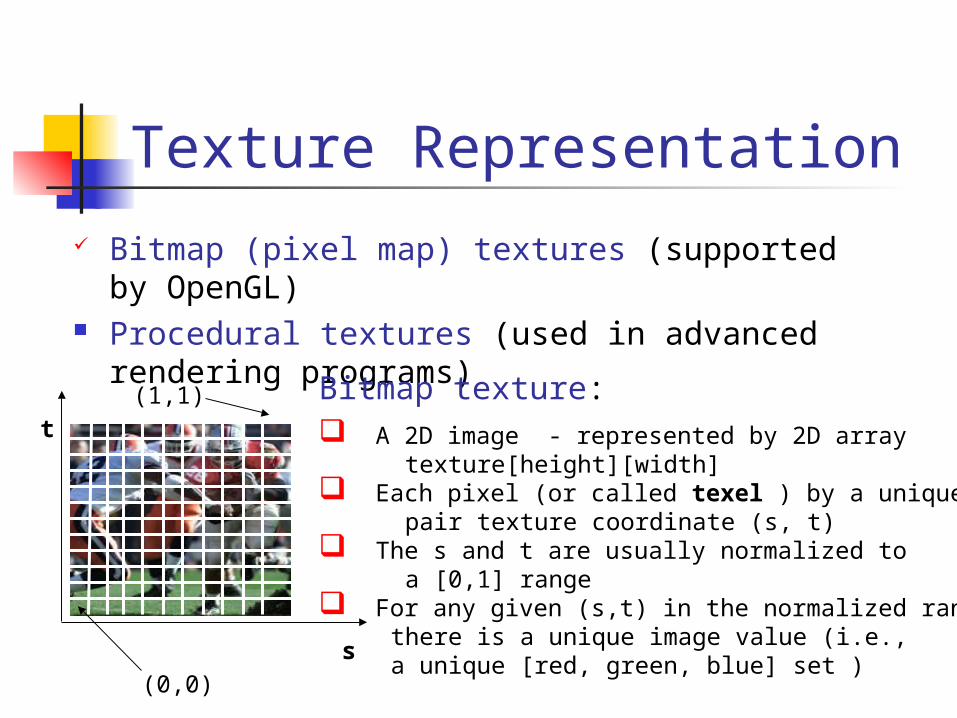
Texture Representation Bitmap (pixel map) textures (supported by
OpenGL) Procedural textures (used in advanced
rendering programs)Bitmap texture: A 2D image - represented by 2D array texture[height][width] Each pixel (or called texel ) by a unique pair texture coordinate (s, t) The s and t are usually normalized to a [0,1] range For any given (s,t) in the normalized range, there is a unique image value (i.e., a unique [red, green, blue] set )
s
t
(0,0)
(1,1)
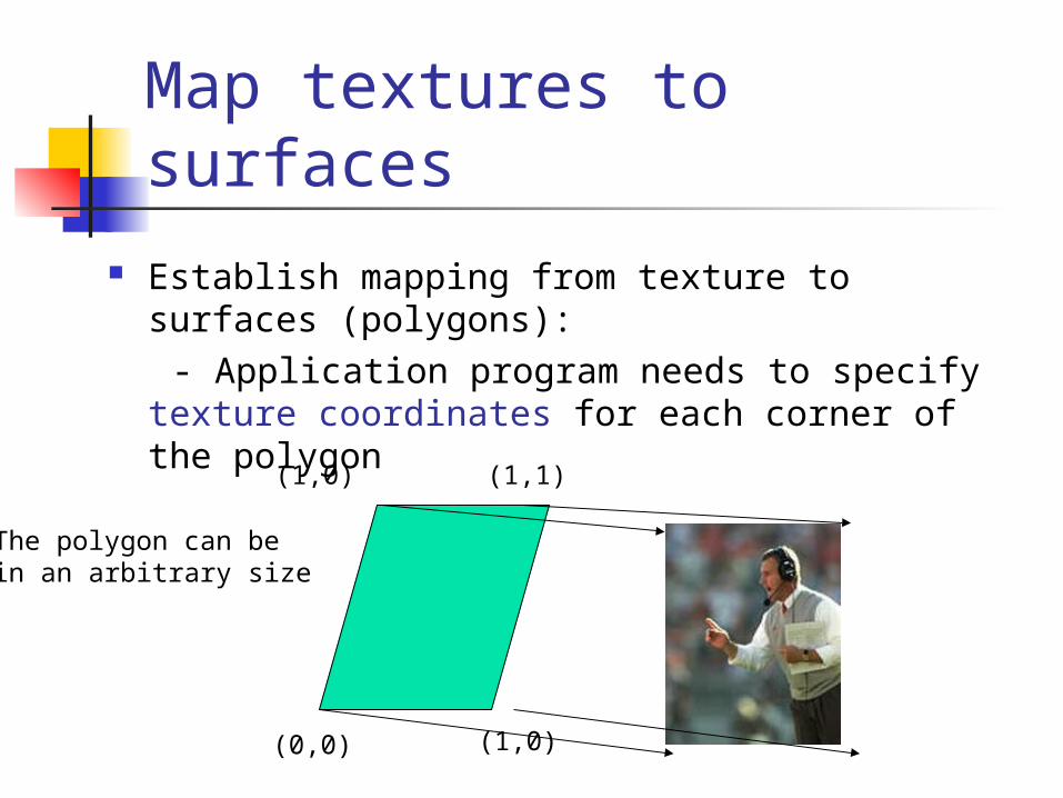
Map textures to surfaces Establish mapping from texture to surfaces
(polygons): - Application program needs to specify texture
coordinates for each corner of the polygon
The polygon can bein an arbitrary size
(0,0) (1,0)
(1,0) (1,1)
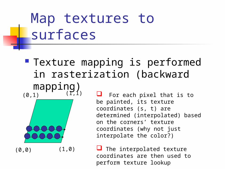
Map textures to surfaces
Texture mapping is performed in rasterization (backward mapping)
(0,0) (1,0)
(0,1) (1,1) For each pixel that is to be painted, its texture coordinates (s, t) are determined (interpolated) based on the corners’ texture coordinates (why not just interpolate the color?) The interpolated texture coordinates are then used to perform texture lookup

Texture Mapping
S
t
3D geometry
2D image
2D projection of 3D geometry
1. projection
2. texture lookup
3. patch texel
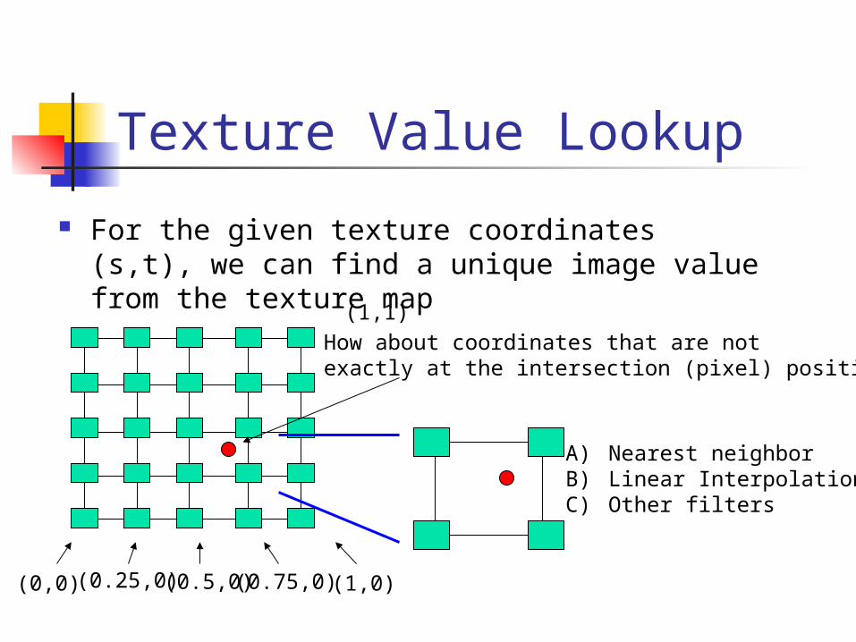
Texture Value Lookup
For the given texture coordinates (s,t), we can find a unique image value from the texture map
(0,0)
(1,1)
(0.25,0) (0.5,0) (0.75,0) (1,0)
How about coordinates that are not exactly at the intersection (pixel) positions?
A) Nearest neighborB) Linear InterpolationC) Other filters
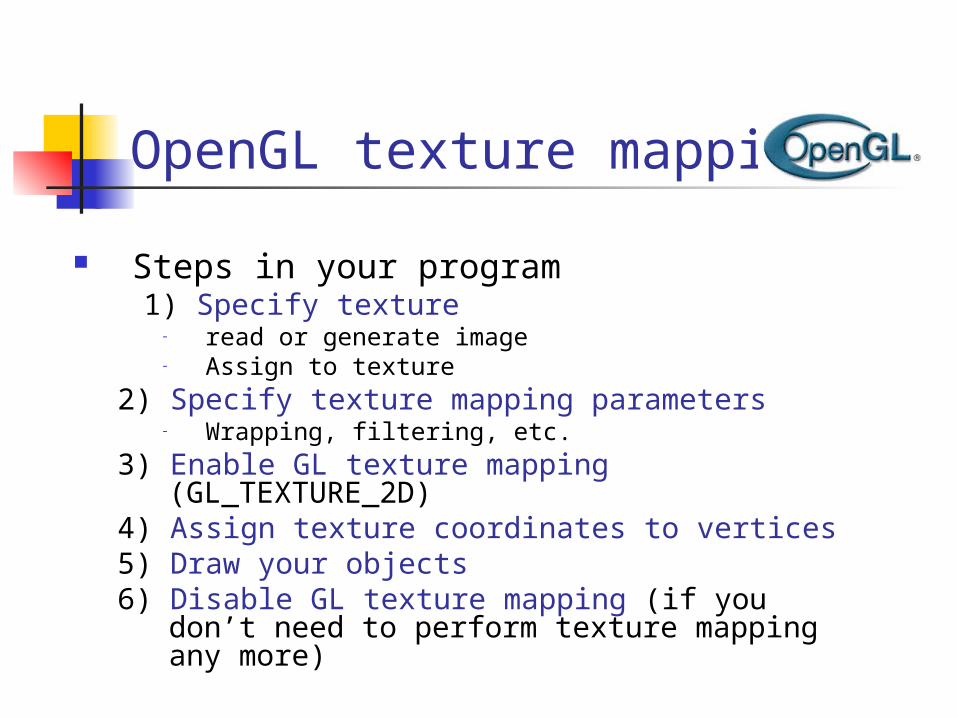
OpenGL texture mapping
Steps in your program 1) Specify texture
- read or generate image- Assign to texture
2) Specify texture mapping parameters - Wrapping, filtering, etc.
3) Enable GL texture mapping (GL_TEXTURE_2D)
4) Assign texture coordinates to vertices5) Draw your objects6) Disable GL texture mapping (if you don’t
need to perform texture mapping any more)

Specify textures Load the texture map from main memory to
texture memory glTexImage2D(Glenum target, Glint level, Glint
iformat, int width, int height, int border, Glenum format,
Glenum type, Glvoid* img) Example:
glTeximage2D(GL_TEXTURE_2D, 0, GL_RGB, 64, 64, 0, GL_RGB, GL_UNSIGNED_BYTE, myImage);
(myImage is a 2D array: GLuByte myImage[64][64][3]; )
The dimensions of texture images must be powers of 2
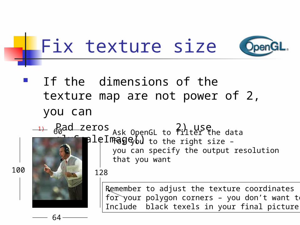
Fix texture size
If the dimensions of the texture map are not power of 2, you can
1) Pad zeros 2) use gluScaleImage()
100
60
128
64
Ask OpenGL to filter the data for you to the right size – you can specify the output resolutionthat you want
Remember to adjust the texture coordinatesfor your polygon corners – you don’t want to Include black texels in your final picture
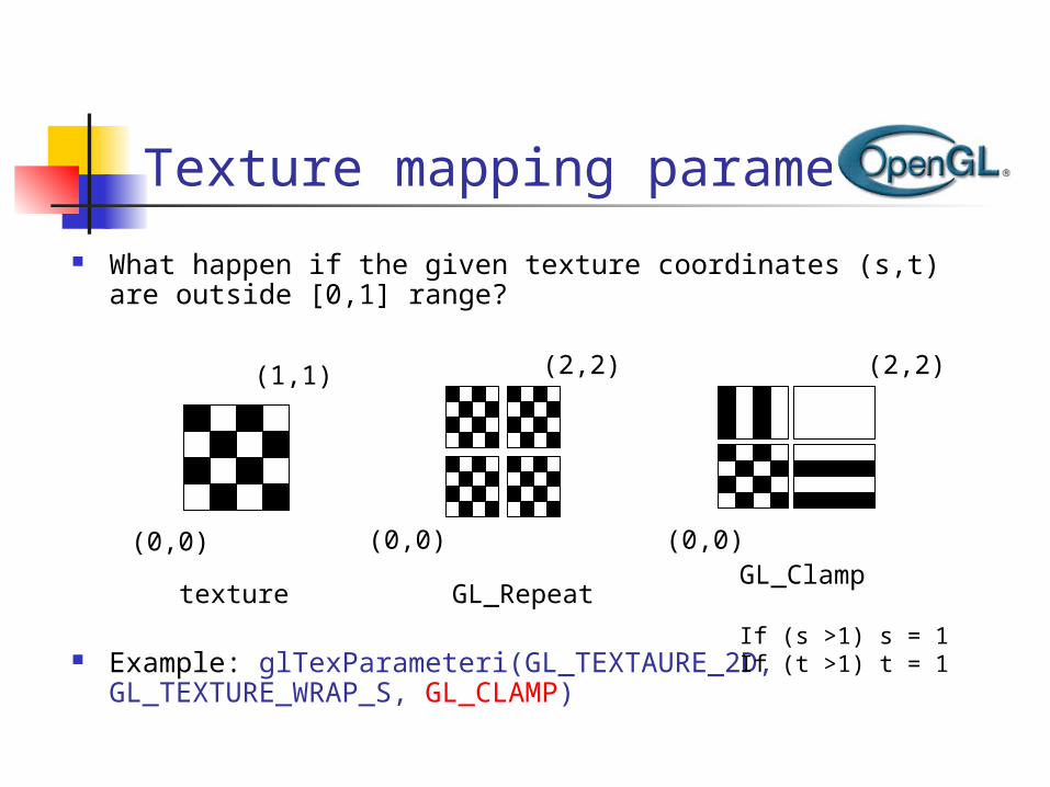
Texture mapping parameters
What happen if the given texture coordinates (s,t) are outside [0,1] range?
Example: glTexParameteri(GL_TEXTAURE_2D, GL_TEXTURE_WRAP_S, GL_CLAMP)
(0,0)
(1,1)
texture GL_Repeat
(0,0)
(2,2)
(0,0)
(2,2)
GL_Clamp
If (s >1) s = 1 If (t >1) t = 1
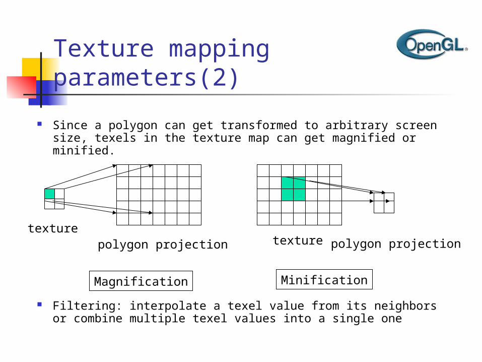
Texture mapping parameters(2)
Since a polygon can get transformed to arbitrary screen size, texels in the texture map can get magnified or minified.
Filtering: interpolate a texel value from its neighbors or combine multiple texel values into a single one
texturepolygon projection
Magnification
texture polygon projection
Minification

2) Linear interpolate the neighbors (better quality, slower)
glTexParameteri(GL_TEXTURE_2D, GL_TEXTURE_MIN_FILTER, GL_LINEAR)
1) Nearest Neighbor (lower image quality)
glTexParameteri(GL_TEXTURE_2D, GL_TEXTURE_MIN_FILTER, GL_NEAREST);
Texture mapping parameters(3)
OpenGL texture filtering:
Or GL_TEXTURE_MAX_FILTER
Texture color blending
Determin how to combine the texel color and the object color
GL_MODULATE – multiply texture and object color GL_BLEND – linear combination of texture and object
color GL_REPLACE – use texture color to replace object
color
Example: glTexEnvf(GL_TEXTURE_ENV, GL_TEXTURE_ENV_MODE, GL_REPLACE);

Enable (Disable) Textures
Enable texture – glEnable(GL_TEXTURE_2D)
Disable texture – glDisable(GL_TEXTURE_2D)
Remember to disable texture mapping when you draw non-textured polygons
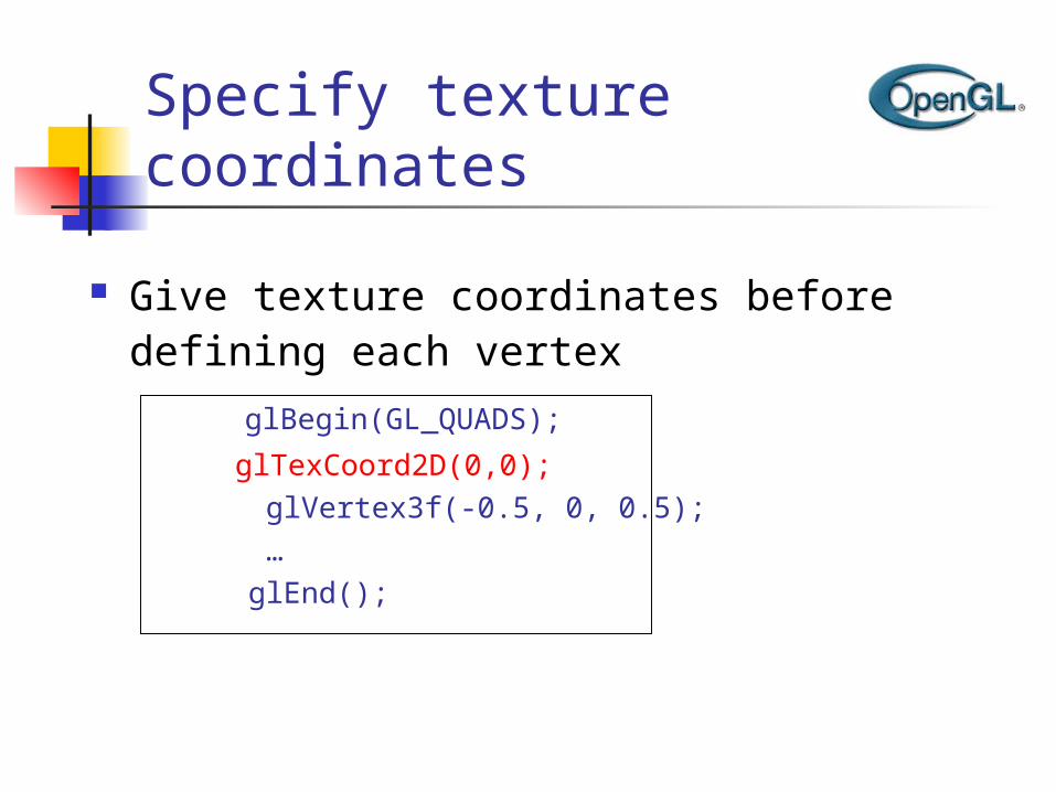
Specify texture coordinates
Give texture coordinates before defining each vertex
glBegin(GL_QUADS);
glTexCoord2D(0,0); glVertex3f(-0.5, 0, 0.5); … glEnd();
Transform texture coordinates
All the texture coordinates are multiplied by Gl_TEXTURE matrix before in use
To transform texture coordinates, you do: glMatrixMode(Gl_TEXTURE); Apply regular transformation functions Then you can draw the textured objects

Put it all together
…glTexParameteri(GL_TEXTURE_2D, GL_TEXTURE_WRAP_S, GL_REPEAT); glTexParameteri(GL_TEXTURE_2D, GL_TEXTURE_WRAP_T, GL_REPEAT); glTexParameteri(GL_TEXTURE_2D, GL_TEXTURE_MAG_FILTER,
GL_NEAREST);glTexParameteri(GL_TEXTURE_2D, GL_TEXTURE_MIN_FILTER, GL_NEAREST); glTexEnvf(GL_TEXTURE_ENV, GL_TEXTURE_ENV_MODE, GL_REPLACE); …glEnable(GL_TEXTURE_2D); glTexImage2D(GL_TEXTURE_2D, 0, GL_RGB, 64, 64, 0, GL_RGB,
GL_UNSIGNED_BYTE, mytexture);
Draw_picture1(); // define texture coordinates and vertices in the function ….

Projector Functions How do we map the texture onto a arbitrary (complex)
object? Construct a mapping between the 3-D point to an
intermediate surface
Idea: Project each object point to the intermediate surface with a parallel or perspective projection The focal point is usually placed inside the object
Plane Cylinder Sphere Cube
Planar projector
courtesy of R. Wolfe

Planar Projector
Orthographic projection
onto XY plane:
u = x, v = y
...onto YZ plane ...onto XZ plane
courtesy of R. Wolfe
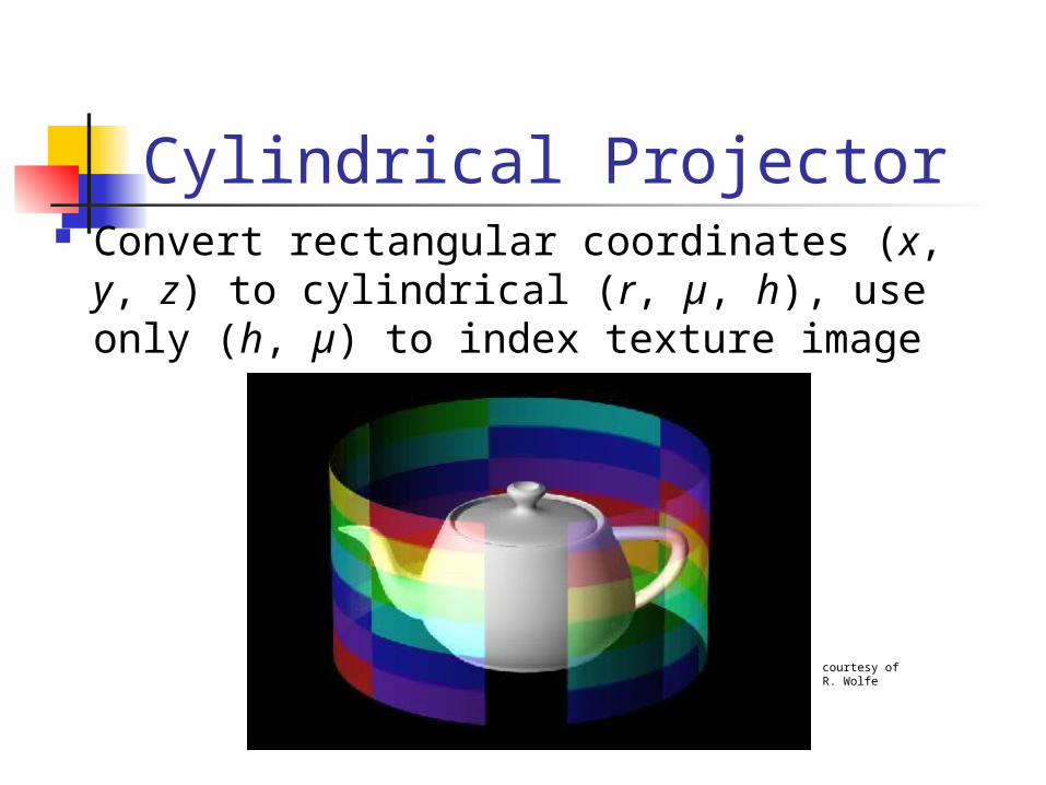
Cylindrical Projector Convert rectangular coordinates (x, y, z) to
cylindrical (r, µ, h), use only (h, µ) to index texture image
courtesy of R. Wolfe

Spherical Projector
Convert rectangular coordinates (x, y, z) to spherical (, )
courtesy of R. Wolfe

Parametric Surfaces A parameterized surface patch
x = f(u, v), y = g(u, v), z = h(u, v) You will get to these kinds of surfaces in
CSE 784.
courtesy of R. Wolfe

Texture Rasterization Texture coordinates are interpolated from
polygon vertices just like … remember … Color : Gouraud shading Depth: Z-buffer First along polygon edges between vertices Then along scanlines between left and right
sides
from Hill
courtesy of H. Pfister
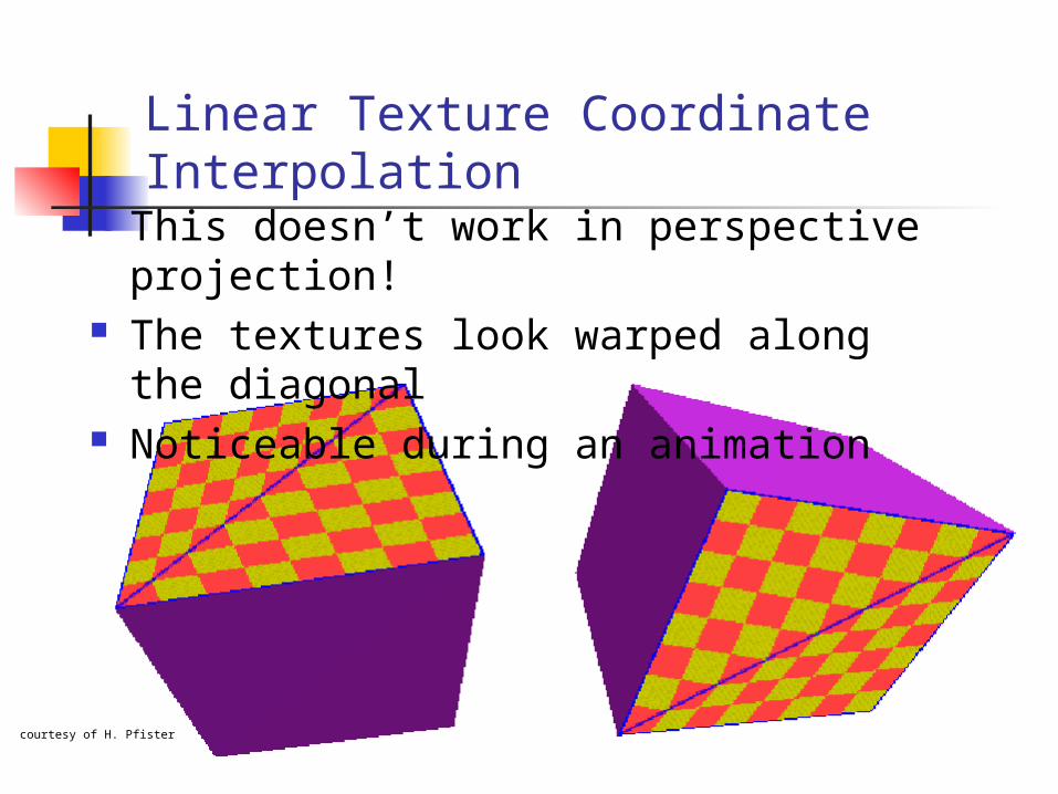
Linear Texture Coordinate Interpolation
This doesn’t work in perspective projection!
The textures look warped along the diagonal
Noticeable during an animation

Why? Equal spacing in screen (pixel) space is not the
same as in texture space in perspective projection Perspective foreshortening
from Hill
courtesy ofH. Pfister

Perspective-Correct Texture Coordinate Interpolation
Interpolate (tex_coord/w) over the polygon, then do perspective divide after interpolation
Compute at each vertex after perspective transformation “Numerators” s/w, t/w “Denominator” 1/w
Linearly interpolate 1/w, s/w, and t/w across the polygon
At each pixel Perform perspective division of interpolated texture
coordinates (s/w, t/w) by interpolated 1/w (i.e., numerator over denominator) to get (s, t)
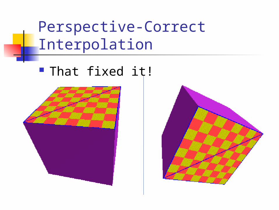
Perspective-Correct Interpolation
That fixed it!
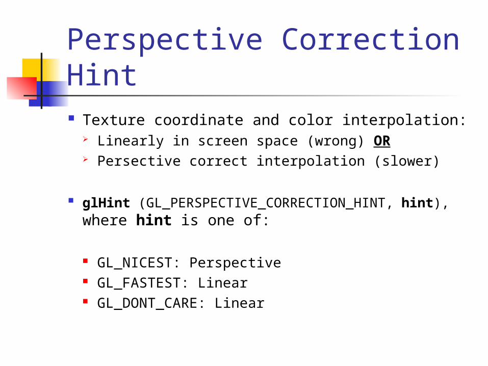
Perspective Correction Hint Texture coordinate and color interpolation:
Linearly in screen space (wrong) OR Persective correct interpolation (slower)
glHint (GL_PERSPECTIVE_CORRECTION_HINT, hint), where hint is one of:
GL_NICEST: Perspective GL_FASTEST: Linear GL_DONT_CARE: Linear
![Reconstructing Generalized Staircase Polygons with Uniform ... · For instance, spiral polygons [15] and tower polygons [8] (also called funnel polygons), can be reconstructed in](https://img.pdfslide.us/doc/110x75/5f649f88f0cc4c6c9f4cdf78/reconstructing-generalized-staircase-polygons-with-uniform-for-instance-spiral.jpg)