Embed Size (px)
Citation preview
7/30/2019 Textbook on Streng 00 Slo Crich
http://slidepdf.com/reader/full/textbook-on-streng-00-slo-crich 1/433
7/30/2019 Textbook on Streng 00 Slo Crich
http://slidepdf.com/reader/full/textbook-on-streng-00-slo-crich 2/433
7/30/2019 Textbook on Streng 00 Slo Crich
http://slidepdf.com/reader/full/textbook-on-streng-00-slo-crich 3/433
7/30/2019 Textbook on Streng 00 Slo Crich
http://slidepdf.com/reader/full/textbook-on-streng-00-slo-crich 4/433
7/30/2019 Textbook on Streng 00 Slo Crich
http://slidepdf.com/reader/full/textbook-on-streng-00-slo-crich 5/433
7/30/2019 Textbook on Streng 00 Slo Crich
http://slidepdf.com/reader/full/textbook-on-streng-00-slo-crich 6/433
MATHEMATICAL TEXTSEdited by PERCEY F. SMITH, Pn.D
Professor of Mathematics in the Sheffield Scientific Schoolof Yale University
Elements of the Differential and Integral Calculus
(Revised Edition)
By W. A. GRANVILLE, PH.D.
Elements of Analytic Geometry
By P. F. SMITH and A. S. GALE, PH.D.
New Analytic Geometry
By P. F. SMITH and A. S. GALE, PH.D.
Introduction to Analytic Geometry .
By P. F. SMITH and A. S. GALE, PH.D.
Advanced Algebra
By H. E. HAWKES, PH.D.
Text-Book on the Strength of Materials (Revised Edition)
By S. E. SLOCUM, PH.D., and E. L. HANCOCK, M.Sc.
Problems in the Strength of MaterialsBy WILLIAM KENT SHEPARD, PH.D.
Plane and Spherical Trigonometry and Four-Place
. Tables of Logarithms
By W. A. GRANVILLE, PH.D.
Plane and Spherical Trigonometry
By W. A. GRANVILLE, PH.D.
Plane Trigonometry and Four-PlaceTables of Logarithms
By W. A. GRANVILLE, PH.D.
Four-Place Tables of Logarithms
By W. A. GRANVILLE, PH.D.Theoretical Mechanics
By P. F. SMITH and W. R. LONGLEY, PH.D.
First Course in Algebra
By H. E. HAWKES, PH.D., WILLIAM A. LUBY, A.B.,and FRANK C. TOUTON, Pn.B.
Second Course in Algebra
By H. E. HAWKES, PH.D., WILLIAM A. LUBY, A.B.,and FRANK C. TOUTON, Pn.B.
Elementary Analysis
By P. F. SMITH and W. A. GRANVILLE, Pn.D
7/30/2019 Textbook on Streng 00 Slo Crich
http://slidepdf.com/reader/full/textbook-on-streng-00-slo-crich 7/433
TEXT-BOOK ON THE
STRENGTH OF MATERIALS
BY
S. E. SLOCUM, B.E., PH.D.
PROFESSOR OF APPLIED MATHEMATICS IN THE UNIVERSITY OF CINCINNATI
E. L. HANCOCK, M.S.
PROFESSOR OF APPLIED MECHANICS IN WORCESTER POLYTECHNIC INSTITUTE
REVISED EDITION
GINN AND COMPANYBOSTON NEW YORK CHICAGO LONDON
7/30/2019 Textbook on Streng 00 Slo Crich
http://slidepdf.com/reader/full/textbook-on-streng-00-slo-crich 8/433
COPYRIGHT, 1906, 1911, BY
S. E. SLOCUM AND E. L. HANCOCK
ALL RIGHTS RESERVED
811.10
gfce
GINN AND COMPANY PRO-
PRIETORS BOSTON U.S.A.

7/30/2019 Textbook on Streng 00 Slo Crich
http://slidepdf.com/reader/full/textbook-on-streng-00-slo-crich 9/433
PREFACE
Five years of extensive use of this book, since the appearance of
the first edition, havebrought
to the authors from various sources
numerous suggestions relating to its improvement. In particular the
authors wish to acknowledge their indebtedness to Professor Irving P.
Church of Cornell University and to Professor George R Chatburn of
the University of Nebraska for their unfailing interest and frequent
valuable suggestions.
To utilize the material so obtained, the text has been thoroughly
revised. In making this revision the aim of the authors has been
twofold: first, to keep the text abreast of the most recent practical
developments of the subject; and second, to simplify the method
of presentation so as to make the subject easily intelligible to the
average technical student of junior grade, as well as to lessen the
work of instruction.
Besides correcting the errors inevitable to a first edition, special
attention has been given to amplifying the explanation wherever ex-
perience in using the book as a text has indicated it to be desirable.
This applies especially to the articles on Poisson's ratio, the theorem
of three moments, the calculation of the stress in curved members,
the relation of Guest's and Eankine's formulas to the design of shafts
subjected to combined stresses, etc.
Considerable new material has also been added. In Part I a set
of tables has been placed at the beginning of the volume to facilitate
numerical calculations. Other important additions are articles on
the design of reenforced concrete beams, shrinkage and forced fits, the
design of eccentrically loaded columns, the design and efficiency of
riveted joints, the general theory of the torsion of springs, practical
formulas for the collapse of tubes, and an extension of the method of
least work to a widevariety
ofpractical problems.
This last includes
7/30/2019 Textbook on Streng 00 Slo Crich
http://slidepdf.com/reader/full/textbook-on-streng-00-slo-crich 10/433
vi STRENGTH OF MATERIALS
the derivation and application of the Fraenkel formula for the bending
deflection of beams, and also a simple general formula for the shearing
deflection of beams, never before published.
Nearly one hundred and fifty original problems have also been
added to Part I. These problems are designed not merely to provide
numerical exercises on the text, but have been selected throughout
with the specific purpose of emphasizing the practical importance of
the subject and extending the range of its application as widely as
possible. Many of them are practical shop problems brought up by
students in the
cooperative engineering
course at the
University
of
Cincinnati.
In Part II the recent advances in the manufacture of steel have
been given special attention, including the properties of vanadium
steel, manganese steel, and high-speed steel. Reenforced concrete
has also received a more adequate treatment, and the chapter on this
subject has been thoroughly revised and modernized. The chapter on
timber has also received an equally thorough revision, and considerable
material on preservative processes has been added.
In both the first edition and the present revision, Part I, covering
the analytical treatment of the subject, is the work of S. E. Slocum,
and Part II, presenting the experimental or laboratory side, is the
work of E. L Hancock.TH AUTHORg
7/30/2019 Textbook on Streng 00 Slo Crich
http://slidepdf.com/reader/full/textbook-on-streng-00-slo-crich 11/433
CONTENTSPART I MECHANICS OF MATERIALS
CHAPTER I
ELASTIC PROPERTIES OF MATERIALSPAGES
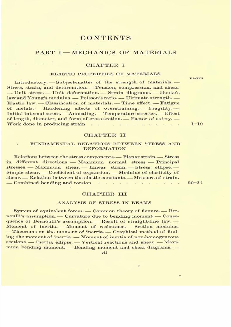
Introductory. Subject-matter of the strength of materials.
Stress, strain, and deformation. Tension, compression, and shear.
Unit stress. Unit deformation. Strain diagrams. Hooke's
law and Young's modulus. Poisson's ratio. Ultimate strength.
Elastic law. Classification of materials. Time effect. Fatigue
of metals. Hardening effects of overstraining. Fragility.
Initial internal stress. Annealing. Temperature stresses. Effect
of length, diameter, and form of cross section. Factor of safety.
Work done in producing strain 1~19
CHAPTER II
FUNDAMENTAL RELATIONS BETWEEN STRESS ANDDEFORMATION
Relations between the stress components. Planar strain. Stress
in different directions. Maximum normal stress. Principal
stresses. Maximum shear. Linear strain. Stress ellipse.
Simple shear. Coefficient of expansion. Modulus of elasticity of
shear. Relation between the elastic constants. Measure of strain.
Combined bending and torsion 20-34
CHAPTER III
ANALYSIS OF STRESS IN BEAMS
System of equivalent forces. Common theory of flexure. Ber-
noulli's assumption. Curvature due to bending moment. Conse-
quence of Bernoulli's assumption. Result of straight-line law.
Moment of inertia. Moment of resistance. Section modulus.
Theorems on the moment of inertia. Graphical method of find-
ing the moment of inertia. Moment of inertia of non-homogeneous
sections. Inertia ellipse. Vertical reactions and shear. Maxi-
mum bending moment. Bending moment and shear diagrams.vii
7/30/2019 Textbook on Streng 00 Slo Crich
http://slidepdf.com/reader/full/textbook-on-streng-00-slo-crich 12/433
viii STRENGTH OF MATERIALS
PAGES
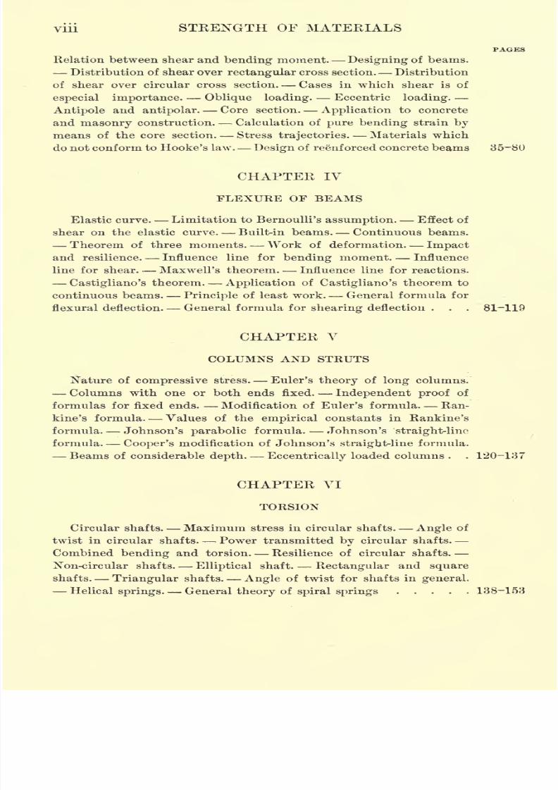
Relation between shear and bending moment. Designing of beams.
Distribution of shear over rectangular cross section. Distribution
of shear over circular cross section. Cases in which shear is of
especial importance. Oblique loading. Eccentric loading.
Antipole and antipolar. Core section. Application to concrete
and masonry construction. Calculation of pure bending strain by
means of the core section. Stress trajectories. Materials which
do not conform to Hooke's law. Design of ree'nforced concrete beams 35-80
CHAPTER IV
FLEXURE OF BEAMS
Elastic curve. Limitation to Bernoulli's assumption. Effect of
shear on the elastic curve. Built-in beams. Continuous beams.
Theorem of three moments. Work of deformation Impact
and resilience. Influence line for bending moment. Influence
line for shear. Maxwell's theorem. Influence line for reactions.
Castigliano's theorem. Application of Castigliano's theorem to
continuous beams.Principle
of least work. General formula for
flexural deflection. General formula for shearing deflection . . . 81-119
CHAPTER V
COLUMNS AND STRUTS
Nature of compressive stress. Euler's theory of long columns.
Columns with one or both ends fixed. Independent proof of
formulas for fixed ends. Modification of Euler's formula. Ran-
kine's formula. Values of the empirical constants in Rankine's
formula. Johnson's parabolic formula. Johnson's straight-line
formula. Cooper's modification of Johnson's straight-line formula.
Beams of considerable depth. Eccentrically loaded columns . . 120-137
CHAPTER VI
TORSION
Circular shafts. Maximum stress in circular shafts. Angle of
twist in circular shafts. Power transmitted by circular shafts.
Combined bending and torsion. Resilience of circular shafts.
Non-circular shafts. Elliptical shaft. Rectangular and square
shafts. Triangular shafts. Angle of twist for shafts in general.
Helical springs. General theory of spiral springs 138-153
7/30/2019 Textbook on Streng 00 Slo Crich
http://slidepdf.com/reader/full/textbook-on-streng-00-slo-crich 13/433
CONTENTS ix
CHAPTER VII
SPHERES AND CYLINDERS UNDER UNIFORM PRESSURE
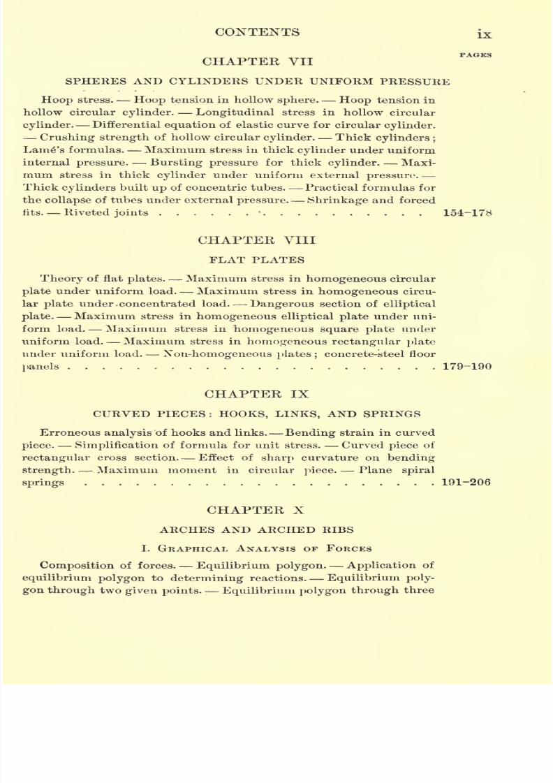
Hoop stress. Hoop tension in hollow sphere. Hoop tension in
hollow circular cylinder. Longitudinal stress in hollow circular
cylinder. Differential equation of elastic curve for circular cylinder.
Crushing strength of hollow circular cylinder. Thick cylinders ;
Lamp's formulas. Maximum stress in thick cylinder under uniform
internal pressure. Bursting pressure for thick cylinder. Maxi-
mum stress in thick cylinder under uniform external pressure.
Thick cylinders built up of concentric tubes. Practical formulas for
the collapse Of tubes under external pressure. Shrinkage and forced
fits. Riveted joints 154-178
CHAPTER VIII
FLAT PLATES
Theory of flat plates. Maximum stress in homogeneous circular
plate under uniform load. Maximum stress in
homogeneouscircu-
lar plate under -concentrated load. Dangerous section of elliptical
plate. Maximum stress in homogeneous elliptical plate under uni-
form load. Maximum stress in homogeneous square plate under
uniform load. Maximum stress in homogeneous rectangular plate
under uniform load. Xon-homogeneous plates ;concrete-steel floor
panels 179-190
CHAPTER IXCURVED PIECES : HOOKS, LINKS, AND SPRINGS
Erroneous analysis of hooks and links. Bending strain in curved
piece. Simplification of formula for unit stress. Curved piece of
rectangular cross section. Effect of sharp curvature on bending
strength. Maximum moment in circular piece. Plane spiral
springs 191-206
CHAPTER X
ARCHES AND ARCHED RIBS
I. GRAPHICAL ANALYSIS OF FORCES
Composition of forces. Equilibrium polygon. Application of
equilibrium polygon to determining reactions. Equilibrium poly-
gonthrough
twogiven points. Equilibrium polygon through
three
7/30/2019 Textbook on Streng 00 Slo Crich
http://slidepdf.com/reader/full/textbook-on-streng-00-slo-crich 14/433
X STRENGTH OF MATERIALS
PAGES
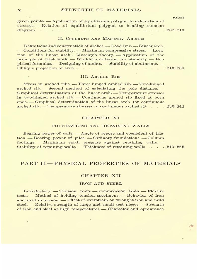
given points. Application of equilibrium polygon to calculation of
stresses Relation of equilibrium polygon to bending moment
diagram / . . . 207-216
II. CONCRETE AND MASONRY ARCHES
Definitions and construction of arches. Load line. Linear arch.
Conditions for stability. Maximum compressive stress. Loca-
tion of the linear arch : Moseley's theory. Application of the
principle of least work. Winkler's criterion for stability. Em-
pirical formulas. Designing of arches. Stability of abutments.
Oblique projection of arch 216-230
III. ARCHED RIBS
Stress in arched ribs. Three-hinged arched rib. Two-hinged
arched rib. Second method of calculating the pole distance.
Graphical determination of the linear arch. Temperature stresses
in two-hinged arched rib. Continuous arched rib fixed at both
ends. Graphical determination of the linear arch for continuous
arched rib. Temperature stresses in continuous arched rib ... 230-242
CHAPTER XI
FOUNDATIONS AND RETAINING WALLS
Bearing power of soils. Angle of repose and coefficient of fric-
tion. Bearing power of piles. Ordinary foundations. Column
footings. Maximum earth pressure against retaining walls.
Stability of retaining walls. Thickness of retaining walls . . . 243-262
PART II PHYSICAL PROPERTIES OF MATERIALS
CHAPTER XII
IRON AND STEEL
Introductory. Tension tests. Compression tests. Flexure
tests. Method of holding tension specimens. Behavior of iron
and steel in tension. Effect of overstrain on wrought iron and mild
steel. Relative strength of large and small test pieces. Strength
of iron and steel at high temperatures. Character and appearance
7/30/2019 Textbook on Streng 00 Slo Crich
http://slidepdf.com/reader/full/textbook-on-streng-00-slo-crich 15/433
CONTENTS XI
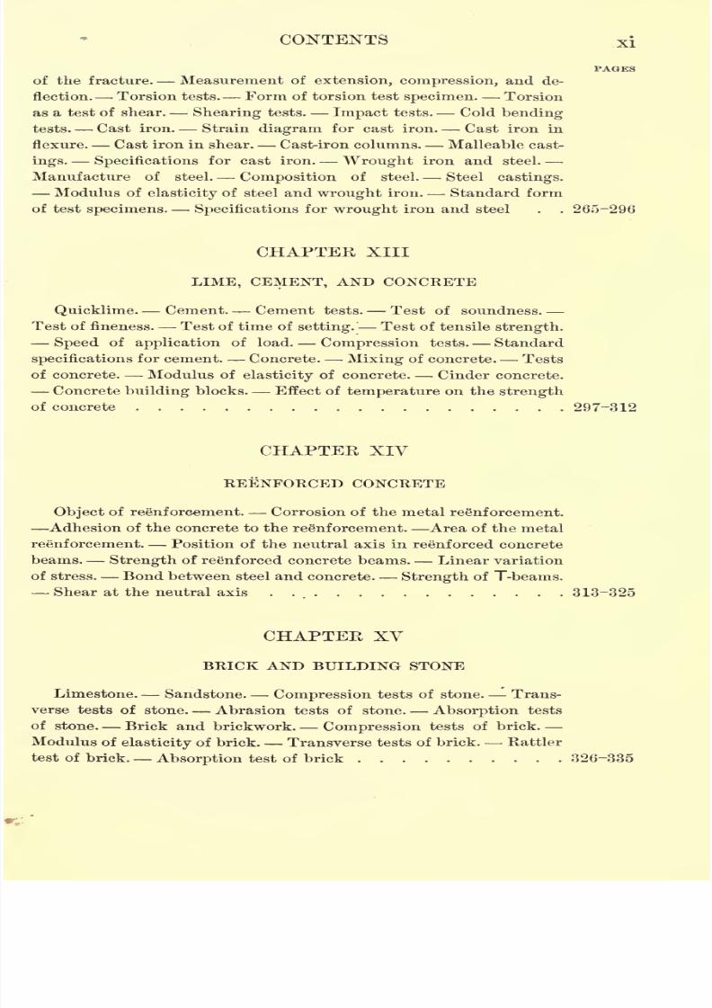
of the fracture. Measurement of extension, compression, and de-
flection. Torsion tests. Form of torsion test specimen. Torsion
as a test of shear. Shearing tests. Impact tests. Cold bending
tests. Cast iron. Strain diagram for cast iron. Cast iron in
flexure. Cast iron in shear. Cast-iron columns. Malleable cast-
ings. Specifications for cast iron. Wrought iron and steel.
Manufacture of steel. Composition of steel. Steel castings.
Modulus of elasticity of steel and wrought iron. Standard form
of test specimens. Specifications for wrought iron and steel . . 265-296
CHAPTER XIII
LIME, CEMENT, AND CONCRETE
Quicklime. Cement. Cement tests. Test of soundness.
Test of fineness. Test of time of setting.' Test of tensile strength.
Speed of application of load. Compression tests. Standard
specifications for cement. Concrete. Mixing of concrete. Tests
of concrete. Modulus of elasticity of concrete. Cinder concrete.
Concrete building blocks. Effect of temperature on the strength
of concrete .... . 297-312
CHAPTER XIV
REENFORCED CONCRETE
Object of reenforcement. Corrosion of the metal reinforcement.
Adhesion of the concrete to the reenforcement. Area of the metal
reenforcement. Position of the neutral axis in reenforced concrete
beams. Strength of reenforced concrete beams. Linear variation
of stress. Bond between steel and concrete. Strength of T-beams.
Shear at the neutral axis . 313-325
CHAPTER XVBRICK AND BUILDING STONE
Limestone. Sandstone. Compression tests of stone. Trans-
verse tests of stone. Abrasion tests of stone. Absorption tests
of stone. Brick and brickwork. Compression tests of brick.
Modulus of elasticity of brick. Transverse tests of brick. Rattler
test of brick. Absorption test of brick 326-335

7/30/2019 Textbook on Streng 00 Slo Crich
http://slidepdf.com/reader/full/textbook-on-streng-00-slo-crich 16/433
xii STRENGTH OF MATERIALS
PAGES
CHAPTER XVI
TIMBER
Structure of timber. Annual rings. Heartwood and sapwood.
Effect of moisture. Strength of timber. Compression tests.
Flexure tests. Shearing tests. Indentation tests. Tension tests.
European tests of timber. Tests made for the tenth census.
Tests made by the Bureau of Forestry. Recent work of the United
States Forest Service. Treated timber. Strength of treated
timber 336-355
CHAPTER XVII
ROPE, WIRE, AND BELTING
Wire. Wire rope. Testing of rope, wire,and belting. Strength
of wire rope. Strength of manila rope. Strength of leather and
rubber belting 356-363
ANSWERS TO PROBLEMS 365-366
INDEX . 367-372
7/30/2019 Textbook on Streng 00 Slo Crich
http://slidepdf.com/reader/full/textbook-on-streng-00-slo-crich 17/433
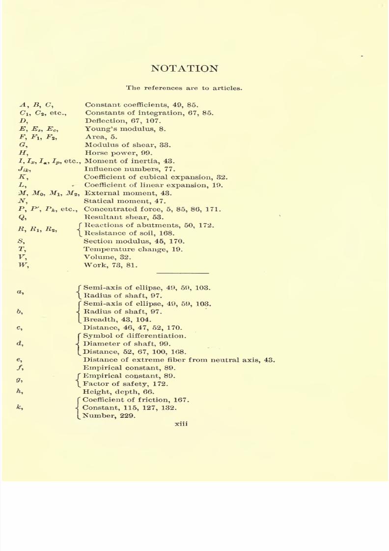
NOTATION
The references are to articles.
A, B, C, Constant coefficients, 49, 85.
C\, Cj, etc., Constants of integration, 67, 85.
D, Deflection, 67, 107.
E, E8 ,Ec , Young's modulus, 8.
F, FI,-F
2 ,
Area, 5.
G, Modulus of shear, 33.
H, Horse power, 99.
7, Ix ,Ja , Ip, etc., Moment of inertia, 43.
Jik ,Influence numbers, 77.
K, Coefficient of cubical expansion, 32.
L, * Coefficient of linear expansion, 19.
M, MQ, MI, M2 ,External moment, 43.
N, Statical moment, 47.
P, P', Ph , etc., Concentrated force, 5, 85, 86, 171.
Q, Resultant shear, 53.
P T> D /Reactions of abutments, 50, 172.
\ Resistance of soil, 168.
S, Section modulus, 45, 170.
T, Temperature change, 19.
F, Volume, 32.
W, Work, 73, 81.
f Semi-axis of ellipse, 49, 59, 103.
\ Radius of shaft, 97.
( Semi-axis of ellipse, 49, 59, 103.
6, J Radius of shaft, 97.
[Breadth, 43, 104.
c, Distance, 46, 47, 52, 170.
CSymbol of differentiation.
d, J Diameter of shaft, 99.
[Distance, 52, 67, 100, 168.
e, Distance of extreme fiber from neutral axis, 43.
/, Empirical constant, 89.
( Empirical constant, 89.
\Factor of safety, 172.
h, Height, depth, 66.
( Coefficient of friction, 167.
fc, \ Constant, 115, 127, 132.
[Number,229.
7/30/2019 Textbook on Streng 00 Slo Crich
http://slidepdf.com/reader/full/textbook-on-streng-00-slo-crich 18/433
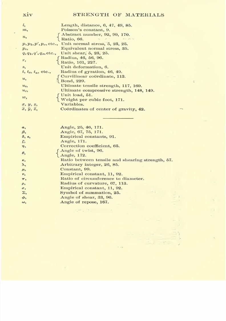
xiv STRENGTH OF MATERIALS
I, Length, distance, 6, 47, 49, 85.
m, Poisson's constant, 9.
f Abstract number, 92, 99, 170.
\ Ratio, 66.
P,P\,P',Px,ete; Unit normal stress, '5, 23, 25.
pe , Equivalent normal stress, 35.
<7> (lit <l'i <lx, etc., Unit shear, 5, 23, 25.
( Radius, 46, 56, 96.
\Ratio, 161, 227.
s, Unit deformation, 6.
,tx,
ta , etc., Radius of gyration, 46, 49.
f Curvilinear coordinate, 113.
I Bond, 229.
Mt ,Ultimate tensile strength, 117, 169.
wc,Ultimate compressive strength, 148, 149.
f Unit load, 51.
[Weight per cubic foot, 171.
x, y, 2, Variables.
x, y, z, Coordinates of center of gravity, 42.
a, Angle, 25, 46, 171.
/3, Angle, 67, 75, 171.
5, e, Empirical constants, 91.
r, Angle, 171.
17, Correction coefficient, 65.
f Angle of twist, 96.
\Angle, 172.
/c,Ratio between tensile and shearing strength, 57.
X, Arbitrary integer, 26, 85.
yu, Constant, 99.
v, Empirical constant, 11, 92.
TT, Ratio of circumference to diameter,
p, Radius of curvature, 67, 113.
0-, Empirical constant, 11, 92.
S, Symbol of summation, 25.
0, Angle of shear, 33, 96.
w, Angleof
repose, 167.
7/30/2019 Textbook on Streng 00 Slo Crich
http://slidepdf.com/reader/full/textbook-on-streng-00-slo-crich 19/433
TABLES OF PHYSICAL AND MATHEMATICAL
CONSTANTS
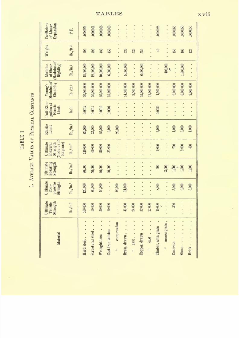
I. AVERAGE VALUES OF PHYSICAL CONSTANTS
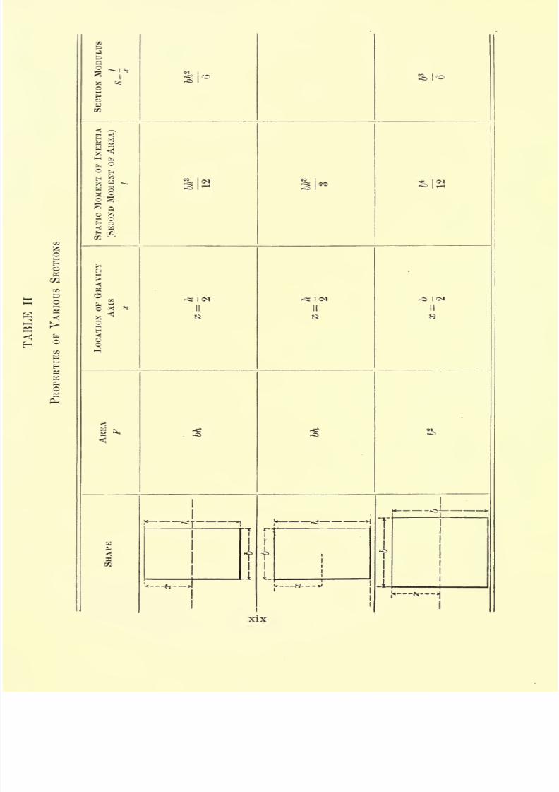
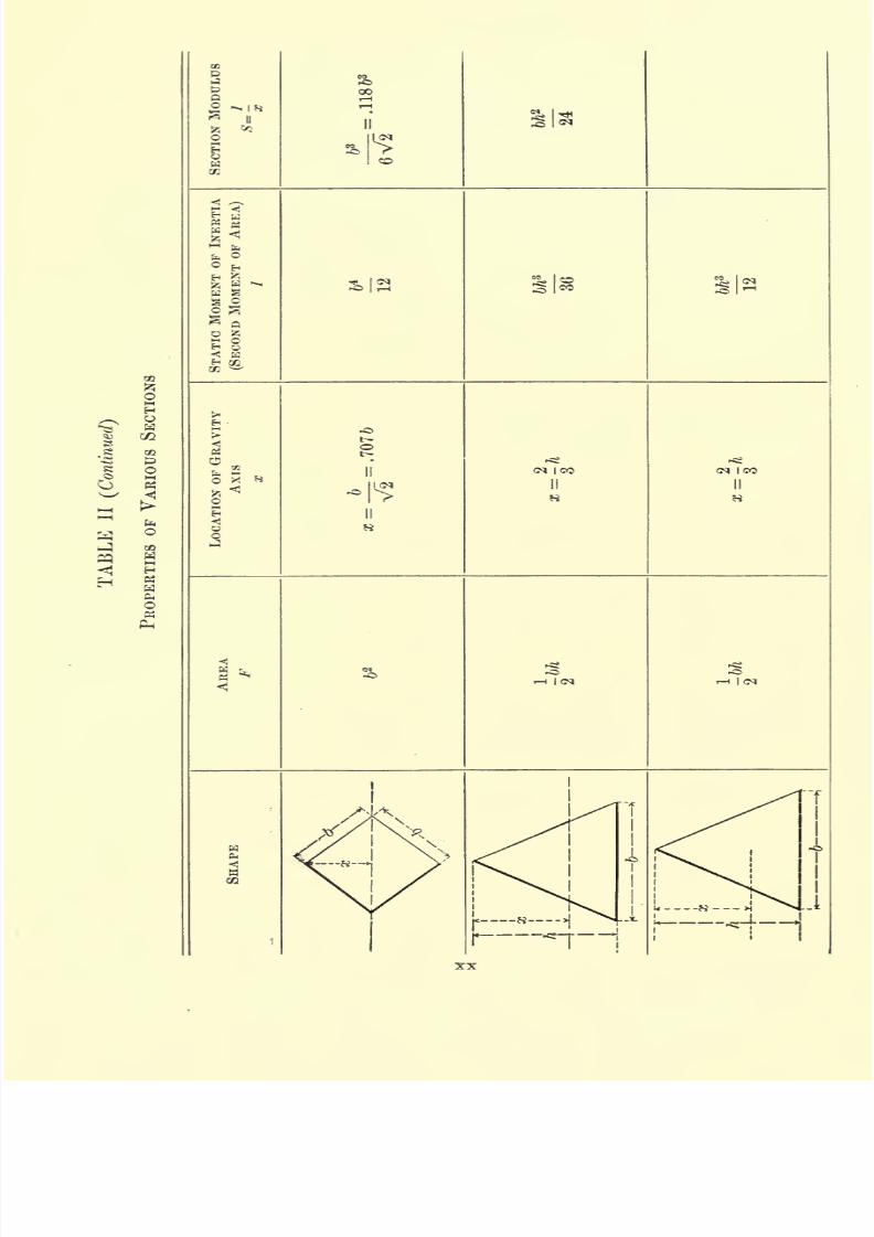
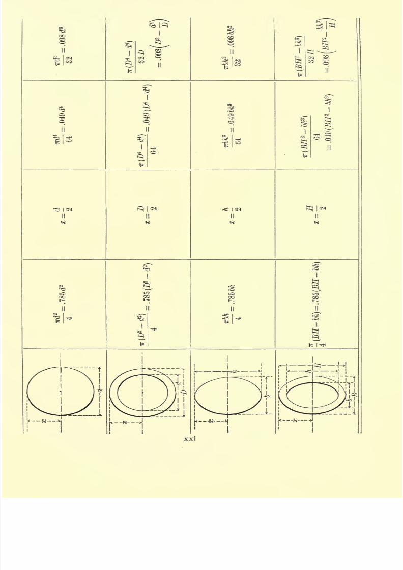
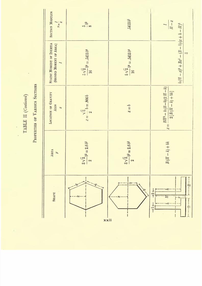
II. PROPERTIES OF VARIOUS SECTIONS
III. PROPERTIES OF STANDARD I-BEAMS
IV. PROPERTIES OF STANDARD CHANNELS
V. PROPERTIES OF STANDARD ANGLES
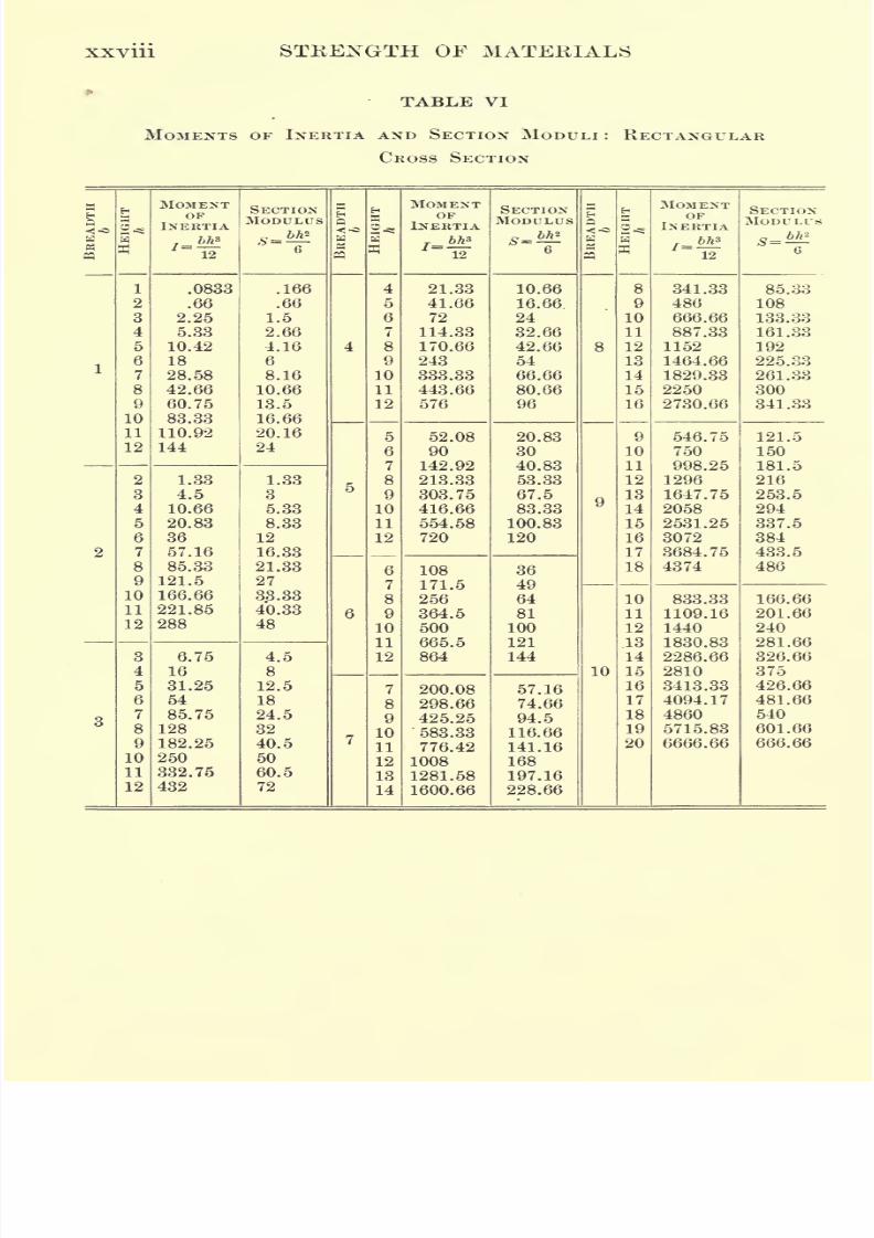
VI. MOMENTS OF INERTIA AND SECTION MODULI:
RECTANGULAR CROSS
SECTION
VII. MOMENTS OF INERTIA AND SECTION MODULI : CIRCULAR CROSS
SECTION
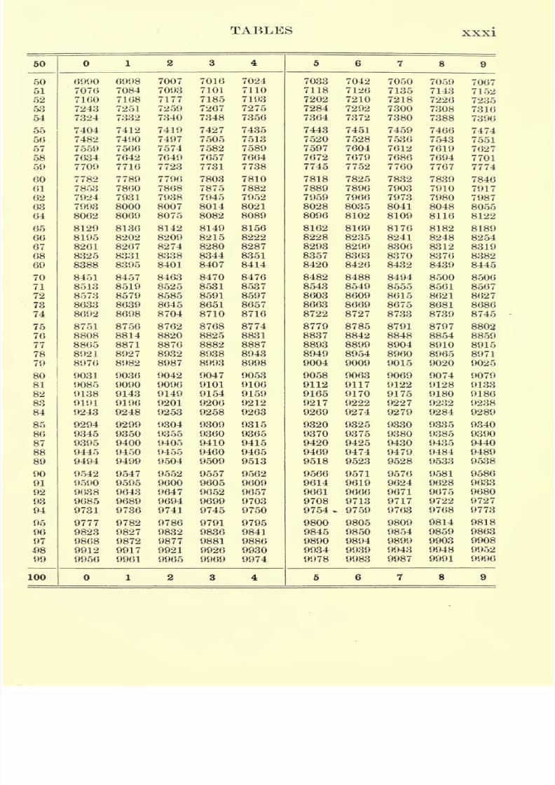
VIII. FOUR-PLACE LOGARITHMS OF NUMBERS
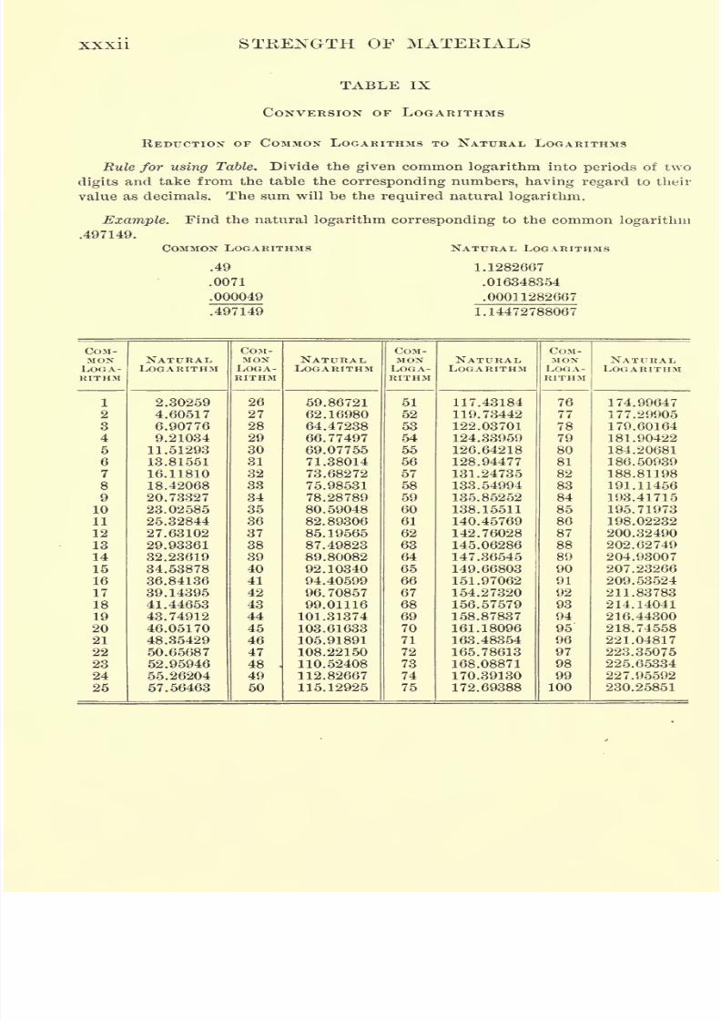
IX. CONVERSION OF LOGARITHMS
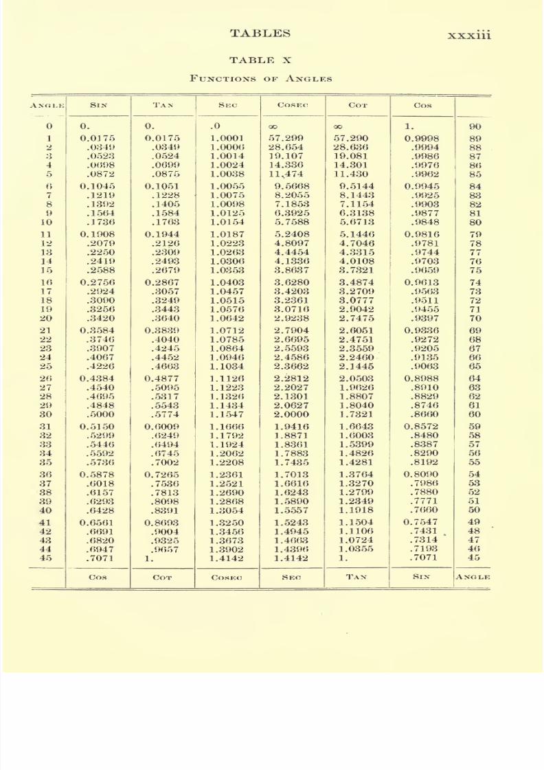
X. FUNCTIONS OF ANGLES
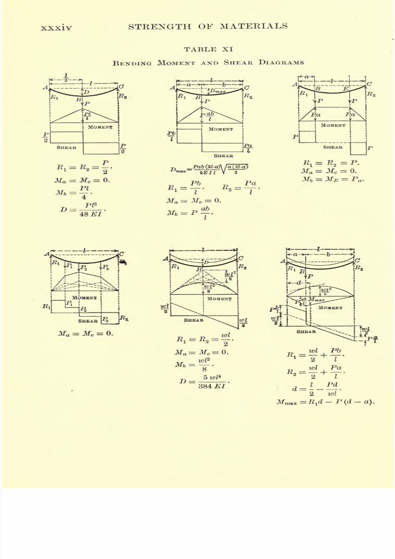
XL BENDING MOMENT AND SHEAR DIAGRAMS
7/30/2019 Textbook on Streng 00 Slo Crich
http://slidepdf.com/reader/full/textbook-on-streng-00-slo-crich 20/433
7/30/2019 Textbook on Streng 00 Slo Crich
http://slidepdf.com/reader/full/textbook-on-streng-00-slo-crich 21/433
TABLES xvii
"! a
"OH
ulushear
lus
o
dity)
Hit 2M ofo
Ki
Young's
Modulus
o
Elasticity
.
Slil
ii <5H 5
flfff
5SoQ|
0202
Ultimate
Tensile
Strength
gf g of
(M (M O3tJ
1 1 i 10000
I
8 g
a s g co co
8 s S S
a
5 "ic 2
1 1 1 1K OQ ^ O
? 8 . .
i
3 Ino S
7/30/2019 Textbook on Streng 00 Slo Crich
http://slidepdf.com/reader/full/textbook-on-streng-00-slo-crich 22/433
XV111 STRENGTH OF MATERIALS
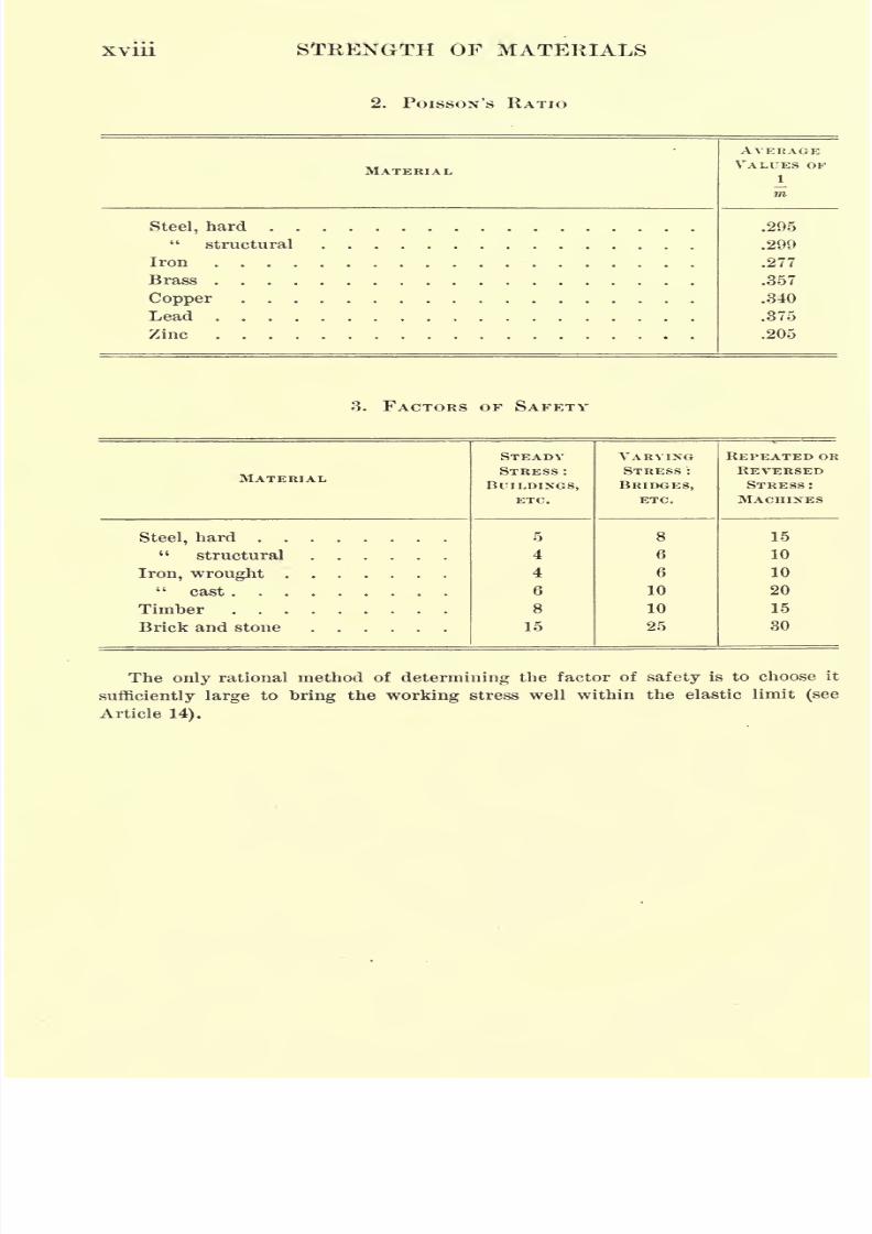
2. POISSON'S RATIO
MATERIAL
7/30/2019 Textbook on Streng 00 Slo Crich
http://slidepdf.com/reader/full/textbook-on-streng-00-slo-crich 23/433
H a
MH
ES
a o x
-^
OI
<N
II
S
xix
7/30/2019 Textbook on Streng 00 Slo Crich
http://slidepdf.com/reader/full/textbook-on-streng-00-slo-crich 24/433
fa O
H
s
* |(NO |rH
SIS!
C<> ICO
||
s
<M ico
II
H
7/30/2019 Textbook on Streng 00 Slo Crich
http://slidepdf.com/reader/full/textbook-on-streng-00-slo-crich 25/433
1
i
ft
SI*
its ITU
7/30/2019 Textbook on Streng 00 Slo Crich
http://slidepdf.com/reader/full/textbook-on-streng-00-slo-crich 26/433
7/30/2019 Textbook on Streng 00 Slo Crich
http://slidepdf.com/reader/full/textbook-on-streng-00-slo-crich 27/433
ttl
h-
xxiii
7/30/2019 Textbook on Streng 00 Slo Crich
http://slidepdf.com/reader/full/textbook-on-streng-00-slo-crich 28/433
XXIV STRENGTH OF MATERIALS
TABLE III
PROPERTIES OF STANDARD I-BEAMS
DEPTHOF
BEAM
7/30/2019 Textbook on Streng 00 Slo Crich
http://slidepdf.com/reader/full/textbook-on-streng-00-slo-crich 29/433
7/30/2019 Textbook on Streng 00 Slo Crich
http://slidepdf.com/reader/full/textbook-on-streng-00-slo-crich 30/433
7/30/2019 Textbook on Streng 00 Slo Crich
http://slidepdf.com/reader/full/textbook-on-streng-00-slo-crich 31/433
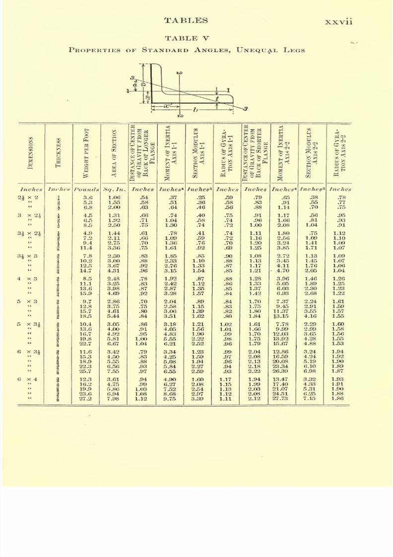
TABLES XXVll
TABLE V
PROPERTIES OF STANDARD ANGLES, UNEQUAL LEGS
7/30/2019 Textbook on Streng 00 Slo Crich
http://slidepdf.com/reader/full/textbook-on-streng-00-slo-crich 32/433
7/30/2019 Textbook on Streng 00 Slo Crich
http://slidepdf.com/reader/full/textbook-on-streng-00-slo-crich 33/433
TABLES XXIX
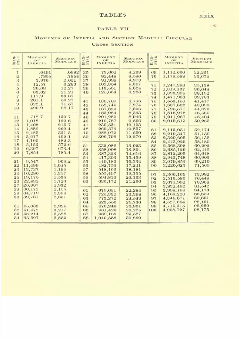
TABLE VII
MOMENTS OF INERTIA AND SECTION MODULI : CIRCULAR
CROSS SECTION
DlAM-
1
ETER
7/30/2019 Textbook on Streng 00 Slo Crich
http://slidepdf.com/reader/full/textbook-on-streng-00-slo-crich 34/433
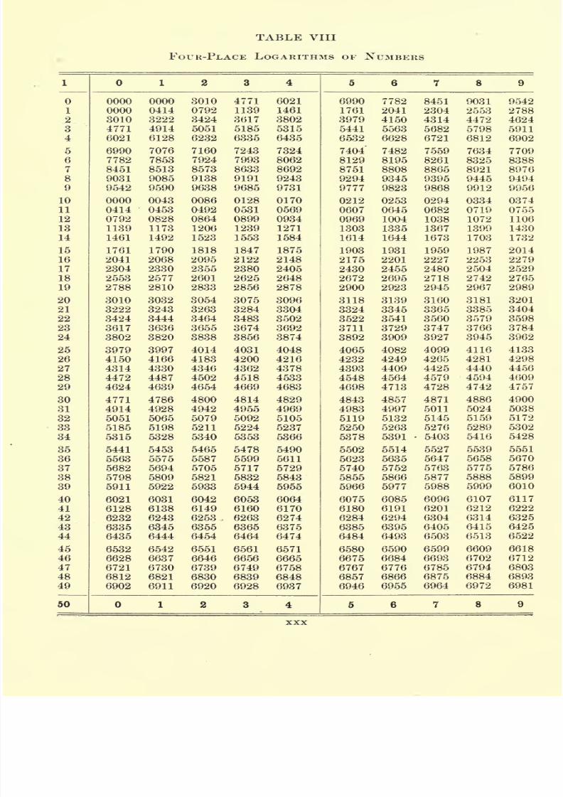
TABLE VIII
FOUR-PLACE LOGARITHMS OF NUMBERS
1
7/30/2019 Textbook on Streng 00 Slo Crich
http://slidepdf.com/reader/full/textbook-on-streng-00-slo-crich 35/433
TABLES xxxi
50
7/30/2019 Textbook on Streng 00 Slo Crich
http://slidepdf.com/reader/full/textbook-on-streng-00-slo-crich 36/433
7/30/2019 Textbook on Streng 00 Slo Crich
http://slidepdf.com/reader/full/textbook-on-streng-00-slo-crich 37/433
7/30/2019 Textbook on Streng 00 Slo Crich
http://slidepdf.com/reader/full/textbook-on-streng-00-slo-crich 38/433
XXXIV STRENGTH OF MATERIALS
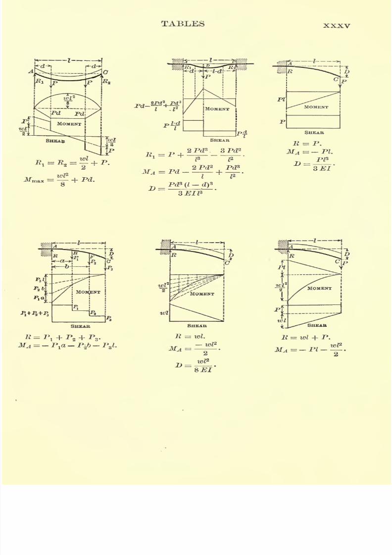
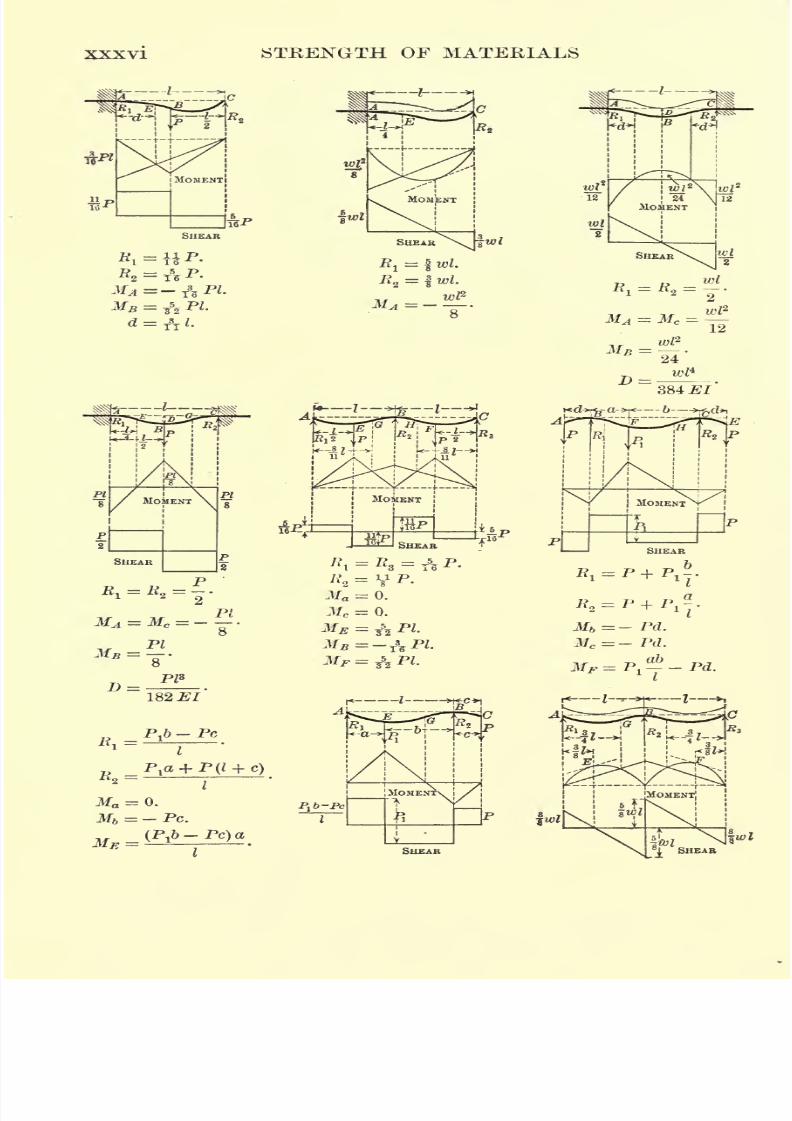
TABLE XI
BENDING MOMENT AND SHEAR DIAGRAMS
48 El
7?Pb
RPa
B1=y
. R2= .
Ma = Mc= 0.
M" = FT
Pi
MOMENT
SHEAR
ti-
B,= E
2= P.
3fa = Mc= 0.
3f& = ME = Pa .
*j *
384 El2 wl
=Rld- P(d-a).
7/30/2019 Textbook on Streng 00 Slo Crich
http://slidepdf.com/reader/full/textbook-on-streng-00-slo-crich 39/433
TABLES XXXV
MOMENT5
SHEAR
2 Pds. 3 PcZ2
SHEAR
~--J >i
SHEAR
= wl.
-wP
1 ^
=~^-^r-4-
SHEAB
E = wl + P.
7/30/2019 Textbook on Streng 00 Slo Crich
http://slidepdf.com/reader/full/textbook-on-streng-00-slo-crich 40/433
STRENGTH OF MATERIALS
7/30/2019 Textbook on Streng 00 Slo Crich
http://slidepdf.com/reader/full/textbook-on-streng-00-slo-crich 41/433
7/30/2019 Textbook on Streng 00 Slo Crich
http://slidepdf.com/reader/full/textbook-on-streng-00-slo-crich 42/433
7/30/2019 Textbook on Streng 00 Slo Crich
http://slidepdf.com/reader/full/textbook-on-streng-00-slo-crich 43/433
7/30/2019 Textbook on Streng 00 Slo Crich
http://slidepdf.com/reader/full/textbook-on-streng-00-slo-crich 44/433
7/30/2019 Textbook on Streng 00 Slo Crich
http://slidepdf.com/reader/full/textbook-on-streng-00-slo-crich 45/433
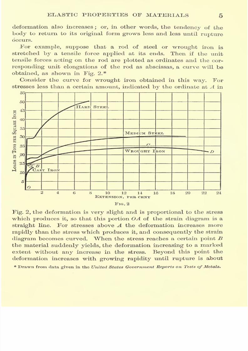
ELASTIC PKOPEKTIES OF MATERIALS
That component of the stress which lies in the plane of the face
tends to slide this face past the adjoining portion of the body, and
for this reason is called the shear, since its action resembles that of a
pair of scissors or shears.
5. Unit stress. If the total stress acting on any cross section of
a body is divided by the area of the cross section, the result is the
stress per unit of area, or unit stress. In what follows p will be used
to denote the unit normal stress and q to denote the unit shear.
Thus if a bar 2 in. square is stretched by a force of 800 lb., the
unit normal stressis
800 lb.
4 in.5
= +2001b./in.2 *
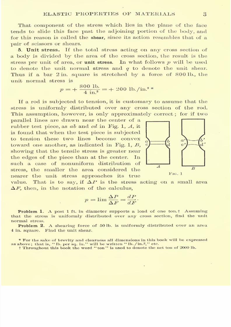
If a rod is subjected to tension, it is customary to assume that the
stress is uniformly distributed over any cross section of the rod.
This assumption, however, is only approximately correct;
for if two
parallel lines are drawn near the center of a
rubber test piece, as ab and cd in Fig. 1, A, it
is found that when the test piece is subjected
to tension these two lines become convex
toward one another, as indicated in Fig. 1, B,
showing that the tensile stress is greater near
the edges of the piece than at the center. In
such a case of nonuniform distribution of
stress, the smaller the area considered the
nearer the unit stress approaches its true
value. That is to say, if AP is the stress acting on a small area
, then, in the notation of the calculus,
AP dP
FIG. 1
Problem 1. A post 1 ft. in diameter supports a load of one ton.f Assuming
that the stress is uniformly distributed over any cross section, find the unit
normal stress.
Problem 2. A shearing force of 50 lb. is uniformly distributed over an area
4 in. square. Find the unit shear.
* For the sake of brevity and clearness all dimensions in this book will be expressed
as above;that is,
"lb. per sq. in." will be written
"lb. /in.'
2," etc.
t Throughout this book the word
"
ton
"
is used to denote the net tonof
2000lb.
7/30/2019 Textbook on Streng 00 Slo Crich
http://slidepdf.com/reader/full/textbook-on-streng-00-slo-crich 46/433
7/30/2019 Textbook on Streng 00 Slo Crich
http://slidepdf.com/reader/full/textbook-on-streng-00-slo-crich 47/433
7/30/2019 Textbook on Streng 00 Slo Crich
http://slidepdf.com/reader/full/textbook-on-streng-00-slo-crich 48/433
7/30/2019 Textbook on Streng 00 Slo Crich
http://slidepdf.com/reader/full/textbook-on-streng-00-slo-crich 49/433
7/30/2019 Textbook on Streng 00 Slo Crich
http://slidepdf.com/reader/full/textbook-on-streng-00-slo-crich 50/433
7/30/2019 Textbook on Streng 00 Slo Crich
http://slidepdf.com/reader/full/textbook-on-streng-00-slo-crich 51/433
ELASTIC PEOPEETIES OF MATERIALS 9
12. Classification of materials. Materials ordinarily used in engi-
neering construction may be divided into three classes, plastic,
supple, and elastic.
Plastic materials are characterized by their inability to resist stress
without receiving permanent deformation. Examples of such mate-
rials are lead, wet clay, mortar before setting, etc.
Supple bodies are characterized by their lack of stiffness. In other
words, supple bodies are capable of undergoing large amounts of
elastic deformation without receiving any plastic deformation. In
this respect plastic and supple bodies exhibit the two extremes of
physical behavior. Examples of supple bodies are rubber, copper,
rope, cables, textile fabrics, etc.
Elastic bodies comprise all the hard and rigid substances, such
as iron, steel, wood, glass, stone, etc. For such bodies the plastic
deformation for any stress within the elastic limit is so small as
to be negligible ;but when the stress surpasses this limit the plastic
deformation becomes measurable and gradually increases until rup-
ture occurs. This permanent deformation is the outward manifes-
tation of a change in the molecular arrangement of the body. For
a stress within the elastic limit the forces of attraction between the
molecules are sufficiently great to hold the molecules in equilibrium ;
but when the stress surpasses the elastic limit, the molecular forces
can nolonger
maintainequilibrium
and a
changein the relation
between the molecules of the body takes place, which results in the
body taking a permanent set.
Eigid bodies have the character of supple bodies when one of
their dimensions is very small as compared with the others. An
instance of this is the flexibility of an iron or steel wire whose
length is very great as compared with its diameter. Furthermore,
rigid bodies behave like plastic bodies when their temperature is
raised to a certain point. For example, when iron and steel are
heated to a cherry redness- they become plastic and acquire the
property of uniting by contact.
13. Time effect. It has been found by experiment that elastic
deformation is manifested simultaneously with the application of a
stress, but that plastic deformation does not appear until much later.
Thus if a constant load acts for a considerable time, the deformation
7/30/2019 Textbook on Streng 00 Slo Crich
http://slidepdf.com/reader/full/textbook-on-streng-00-slo-crich 52/433
7/30/2019 Textbook on Streng 00 Slo Crich
http://slidepdf.com/reader/full/textbook-on-streng-00-slo-crich 53/433
ELASTIC PROPERTIES OF MATERIALS H
of stopping this tendency to spread being by boring a small hole at
either end of the fissure.
Theexplanation
of the above is that for stresses within the elastic
limit the temperature of the body is not raised, and consequently all
the work of deformation is stored up in the body to be given out
again in the form of mechanical energy upon removal of the stress.
If, however, the elastic limit is surpassed, the friction of the mole-
cules sliding on each other generates a certain amount of heat, and
the energy thus transformed into heat is not available for restoring
the body to its original configuration.
15. Hardening effects of overstraining. When such materials as
iron and steel are stressed beyond the elastic limit, it is found upon
removal of the stress that the effect of this overstrain is a hardening
of the material, and that this hardening increases indefinitely with
time. For example, if a plate of soft steel is cold punched, the
material surrounding the hole is severely strained. After an interval
of rest the effects of this overstrain is manifested in a hardening of
the material which continues to increase for months. If the plate is
subsequently stressed, the inability of the portion .overstrained to
yield with the rest of the plate causes the stress to be concentrated
on these portions, and results in a serious weakening of the plate.
Other practical instances of hardening due to overstrain are found
in plates subjected to shearing and planing, armor plates pierced by
cannon balls, plates and bars rolled, hammered, or bent when cold,
wire cold drawn, etc.
16. Fragility. In the solidification of melted bodies different
parts are unequally contracted or expanded. This gives rise to in-
ternal stresses, or what is called latent molecular action, and puts the
body in a state of strain without the application of any external
forces.
For instance,if a
dropof melted
glassis allowed to fall into
water, the outside of the drop is instantly cooled and consequently
contracted, while the inside still remains molten. Since the part
within cannot contract while molten, the contraction of the outside
causes such large internal stresses that the glass is shattered.
Bodies in which latent molecular action exists have the character
of an explosive, in that they are capable of standing a large static
stress but are easily broken by a blow, and for this reason they are
7/30/2019 Textbook on Streng 00 Slo Crich
http://slidepdf.com/reader/full/textbook-on-streng-00-slo-crich 54/433
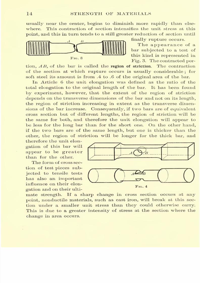
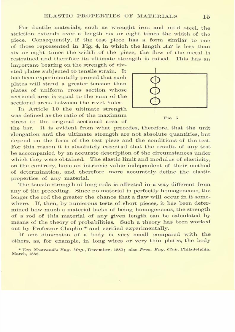
12 STEENGTH OF MATEEIALS
called brittle or fragile. The explanation of fragility is that the vibra-
tions caused by a blow are reinforced by the latent internal stresses
untilrupture
ensues.
17. Initial internal stress. In certain bodies, such as cast iron,
stone, and cement, a state of internal stress may exist without the
application of any external force. This initial internal stress may be
the result of deformation caused by previously applied loads, or maybe occasioned by temperature changes, as mentioned in the preceding
article. The first load applied to such bodies gives them a slight
permanent deformation, but under subsequent loads their behavior
is completely elastic. The first load, in this case, serves to relieve
the strain due to initial internal stress, and consequently the behavior
of the body under subsequent loads is normal. A body which is free
from internal stress is said to be in a "state of ease," a term which
is due to Professor Karl Pearson.
18. Annealing. The process of annealing metals consists in heat-
ing them to a cherry redness and then allowing them to cool slowly.
The effect of this process is to relieve any initial internal stress, or
stress due to overstrain, and put the material in a state of ease.
Hardening due to overstrain is of frequent occurrence in engineering,
and the only certain remedy for it is annealing. If this is imprac-
ticable, hardening can be practically avoided by substituting boring
for punching, sawing for shearing, etc.
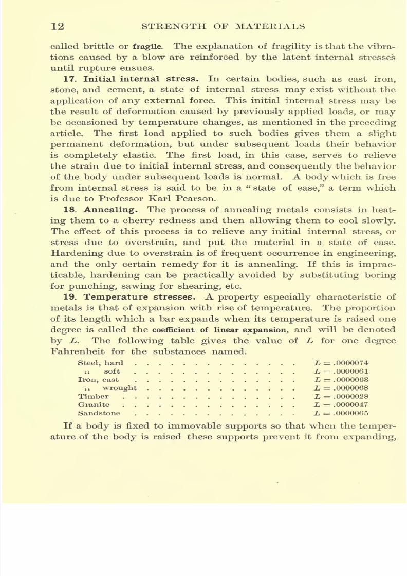
19. Temperature stresses. A property especially characteristic of
metals is that of expansion with rise of temperature. The proportion
of its length which a bar expands when its temperature is raised one
degree is called the coefficient of linear expansion, and will be denoted
by L. The following table gives the value of L for one degree
Fahrenheit for the substances named.
Steel, hard L = .0000074u soft L = .0000061
Iron, cast L = .0000063
(t wrought L = .0000068
Timber L = .0000028
Granite L = .0000047
Sandstone L = .0000065
If a body is fixed to immovable supports so that when the temper-
ature of the body is raised these supports prevent it from expanding,
7/30/2019 Textbook on Streng 00 Slo Crich
http://slidepdf.com/reader/full/textbook-on-streng-00-slo-crich 55/433
7/30/2019 Textbook on Streng 00 Slo Crich
http://slidepdf.com/reader/full/textbook-on-streng-00-slo-crich 56/433
7/30/2019 Textbook on Streng 00 Slo Crich
http://slidepdf.com/reader/full/textbook-on-streng-00-slo-crich 57/433
7/30/2019 Textbook on Streng 00 Slo Crich
http://slidepdf.com/reader/full/textbook-on-streng-00-slo-crich 58/433
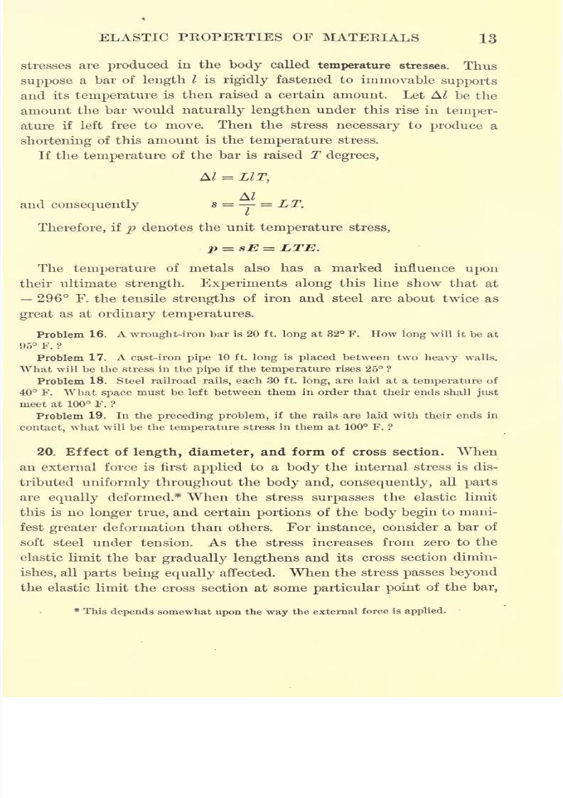
16 STRENGTH OF MATERIALS
may be permanently deformed by stresses below the elastic limit.
The reason for this is that the smallest dimension of such a body
is of the same order of magnitude as the deformation of one of theother dimensions, and consequently Hooke's law does not apply in
this case.
21. Factor of safety. In order to assure absolute stability to any
structure it is clear from what precedes that the actual stresses
occurring in the structure must not exceed the elastic limit of the
material used.
For many materials, however, it is very difficult to determine the
elastic limit, while for other materials for which the determination
is easier, such as iron and steel, the elastic limit is subject to large
variations in value, and it is impossible to do more than assign wide
limits within which it may be expected to lie. For this reason it is
customary to judge the quality of a material by its ultimate strength
instead of by its elastic limit, and assume a certain fraction of the
ultimate strength as the allowable working stress.
The number which expresses the ratio of the ultimate strength to
the working stress is called the factor of safety. Thus
ultimate strengthFactor of safety =
working- stress
No general and rational method of determining the factor of safety
can be given. For, in the first place, formulas deduced from theoret-
ical considerations rest on the assumption that the material considered
is perfectly elastic, homogeneous, and isotropic, an assumption which
is never completely fulfilled. Such formulas give, therefore, only an
approximate idea of the state of stress within the body.
Moreover, the forms of construction members assumed for pur-
posesof calculation do not
exactly correspondto those
actuallyused
;
also certain conditions are unforeseen, and therefore unprovided for,
such as the sinking of foundations, accidental shocks, etc.
In metal constructions rust is another element which tends to
reduce their strength, and in timber constructions the same is
true of wet and dry rot. Care is usually taken to prevent rust and
decay, but the preservative processes used never perfectly accomplish
their object.
7/30/2019 Textbook on Streng 00 Slo Crich
http://slidepdf.com/reader/full/textbook-on-streng-00-slo-crich 59/433
7/30/2019 Textbook on Streng 00 Slo Crich
http://slidepdf.com/reader/full/textbook-on-streng-00-slo-crich 60/433
7/30/2019 Textbook on Streng 00 Slo Crich
http://slidepdf.com/reader/full/textbook-on-streng-00-slo-crich 61/433
7/30/2019 Textbook on Streng 00 Slo Crich
http://slidepdf.com/reader/full/textbook-on-streng-00-slo-crich 62/433
CHAPTER II
FUNDAMENTAL RELATIONS BETWEEN STRESS AND
DEFORMATION
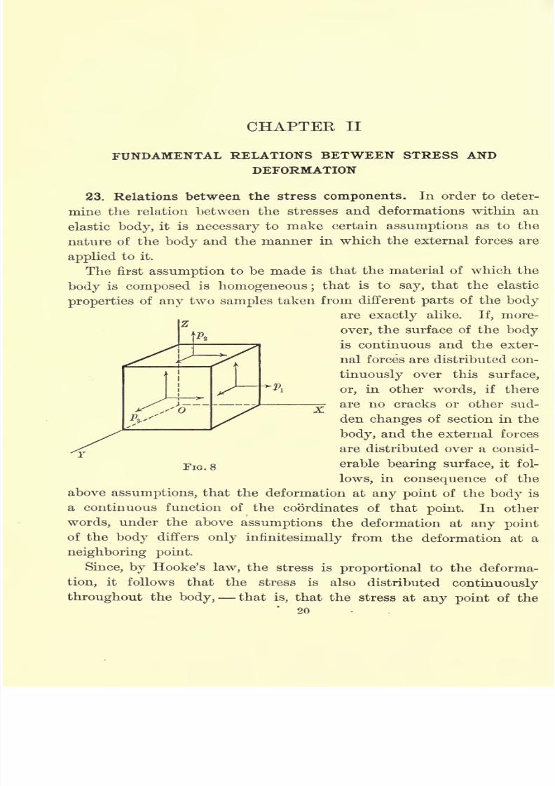
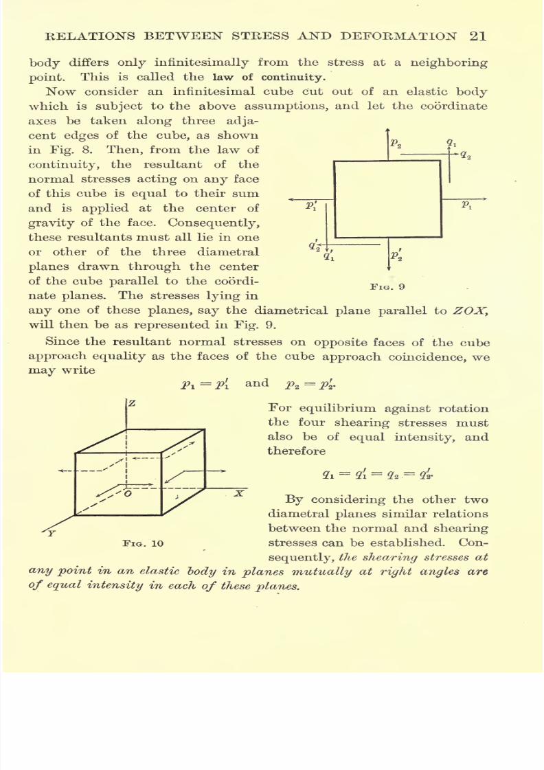
23. Relations between the stress components. In order to deter-
mine the relation between the stresses and deformations within an
elastic body, it is necessary to make certain assumptions as to the
nature of the body and the manner in which the external forces are
applied to it.
The first assumption to be made is that the material of which the
body is composed is homogeneous ;that is to say, that the elastic
properties of any two samples taken from different parts of the body
are exactly alike. If, more-
over, the surface of the body
is continuous and the exter-
nal forces are distributed con-
tinuously over this surface,
or, in other words, if there
are no cracks or other sud-
den changes of section in the
body, and the external forces
are distributed over a consid-
erable bearing surface, it fol-
lows, in consequence of the
aboveassumptions,
that the deformation at
any pointof the
bodyis
a continuous function of the coordinates of that point. In other
words, under the above assumptions the deformation at any point
of the body differs only infiniteshnally from the deformation at a
neighboring point.
Since, by Hooke's law, the stress is proportional to the deforma-
tion, it follows that the stress is also distributed continuously
throughout the body, that is, that the stress at any point of the'
20
X.
7/30/2019 Textbook on Streng 00 Slo Crich
http://slidepdf.com/reader/full/textbook-on-streng-00-slo-crich 63/433

7/30/2019 Textbook on Streng 00 Slo Crich
http://slidepdf.com/reader/full/textbook-on-streng-00-slo-crich 64/433
22 STRENGTH OF MATERIALS
24. Planar strain. If no stress occurs on one pair of opposite faces
of the cube, the resultant stresses on the other faces all lie in one of
the diametralplanes.
This is called theplanar
condition of strain.
Suppose the -axis is drawn in the direction in which no stress
occurs, as shown in Fig. 10. Then the stresses all lie in the plane
parallel to XOY, and the relation between them is as represented in
Fig. 9 of the preceding article.
25. Stress in different directions. As an application of planar
stress, consider a triangular prism on which no stress occurs in
the direction of its length. Let the ^-axis be drawn in the direction
in which no stress occurs, and let a denote the angle which the
FIG. 11
inclined face of the prism makes with the horizontal, as shown in
Fig. 11. Then if dF denotes the area of the inclined face ABCD,
and p', qf
denote the normal and shearing stresses on this face
respectively, p' and q1
can be expressed in terms of px) py)and q by
means of the conditions of equilibrium. Thus, from 2 hor. comps.=
0,
p'dFsma + q'dFcosa pxdF sin a qdFcosa = 0.
Similarly, from 2 vert, comps.=
0,
p'dFcosa q'dFsma pydF cosa qdFsma = 0.
Dividing by dF, these equations become
{p1 sma + q'
cosa px sma q cosa = 0,
\p' cosa q
f
sma pycosa
q sma= 0.
7/30/2019 Textbook on Streng 00 Slo Crich
http://slidepdf.com/reader/full/textbook-on-streng-00-slo-crich 65/433
7/30/2019 Textbook on Streng 00 Slo Crich
http://slidepdf.com/reader/full/textbook-on-streng-00-slo-crich 66/433
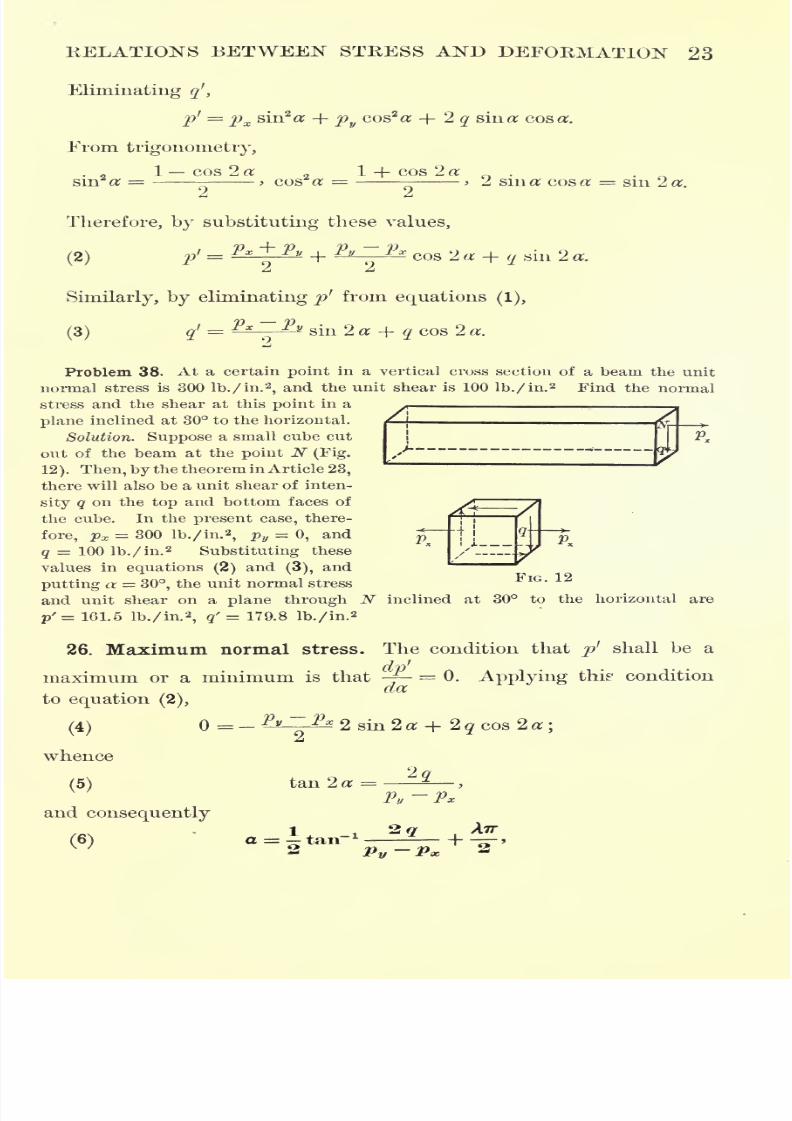
24 STRENGTH OF MATERIALS
where X is zero or an arbitrary integer, either positive or negative.
Equation (6) gives the angles which the planes containing the maxi-
mum and minimum normal stresses make with the horizontal.
From equation (5),
Substituting these values of sin 2 a and cos 2 a in equation (2), the
maximum and minimum values of the normal stress are found to be
rain
27. Principal stresses. Since X in equation (6) is an integer, the
two values of a given by this equation differ by 90, and, conse-
quently, the planes containing the maximum and minimum normal
stresses are at right angles. The maximum and minimum normal
stresses are called principal stresses, and the directions in which they
act, principal directions.
From equation (3), the right member of equation (4) is equal to
2 qf
. But since equation (4) is the condition for a maximum or min-
imum value of the normal stress, it is evident that the normal stress
is greatest or least when the shear is zero.
The results of this article can therefore be summed up in the
following theorem.
Through each point of a body subjected to planar strain there are
two principal directions at right angles, in each of which the shear is
zero.
Problem 39. Find the principal stresses and the principal directions at a point
in a vertical cross section of a beam at which the unit normal stress is 400 lb./in.2
and the unit shear is 250 lb./in.2
Solution. In this problem px = 400 lb./in.2
, pv=
0, and q = 260 lb./in.2
Therefore, from equation (6),
a = - tan-i - +^ = - 25 40.2', or + 64 19.8';
and from equation (7),
Pmax - 620 lb./in. 2, p'min = - 120 lb./in. 2

7/30/2019 Textbook on Streng 00 Slo Crich
http://slidepdf.com/reader/full/textbook-on-streng-00-slo-crich 67/433
7/30/2019 Textbook on Streng 00 Slo Crich
http://slidepdf.com/reader/full/textbook-on-streng-00-slo-crich 68/433
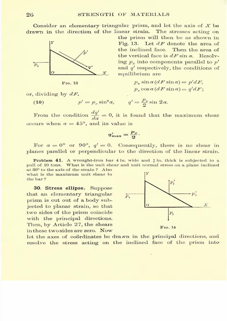
26 STRENGTH OF MATERIALS
Consider an elementary triangular prism, and let the axis of X be
drawn in the direction of the linear strain. The stresses acting on
the
prismwill then be as shown in
Fig. 13. Let dF denote the area of
the inclined face. Then the area of
the vertical face is dF sin a. Resolv-
ing px into components parallel to p'
and qf
respectively, the conditions of
X- equilibrium are
pxsin a (dF sin a) = p'dF,
px cos a (dF sin a)= q'dF;
FIG. 13
or, dividing by dF,
(10) p: = ?=
dq'From the condition -- =0, it is found that the maximum shear
da
occurs when a 45, and its value is
For a or 90, q'= 0. Consequently, there is no shear in
planes parallel or perpendicular to the direction of the linear strain.
Problem 41. A wrought-iron bar 4 in. wide andfin.
thick is subjected to a
pull of 10 tons. What is the unit shear and unit normal stress on a plane inclined
at 30 to the axis of the strain ? Also
what is the maximum unit shear in
the bar ?
30. Stress ellipse. Suppose
that an elementary triangular
prism is cut out of a body sub-
jected to planar strain, so that
two sides of the prism coincide
with the principal directions.
Then, by Article 27, the shears
in these two sides are zero. Now
let the axes of coordinates be drawn in the principal directions, and
resolve the stress acting on theinclined face of the
prisminto
FIG. 14
7/30/2019 Textbook on Streng 00 Slo Crich
http://slidepdf.com/reader/full/textbook-on-streng-00-slo-crich 69/433
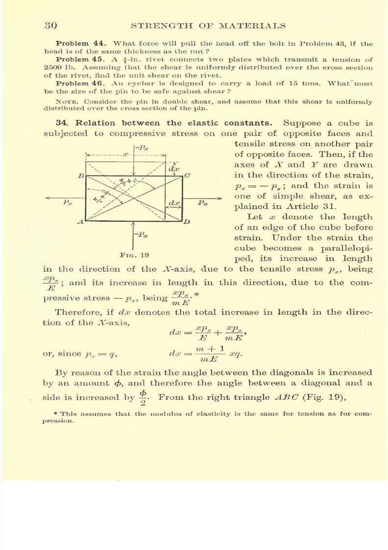
RELATIONS BETWEEN STRESS AND DEFORMATION 27
components parallel to the axes instead of into normal andshearing
stresses as heretofore. Then, from Fig. 14, if dF denotes the area of
the inclined face, the conditions of equilibrium are
p'xdF= pxdF sin a,
p'ydF = pydF cosa
;
whence
P
2 = sin#, = cos a.
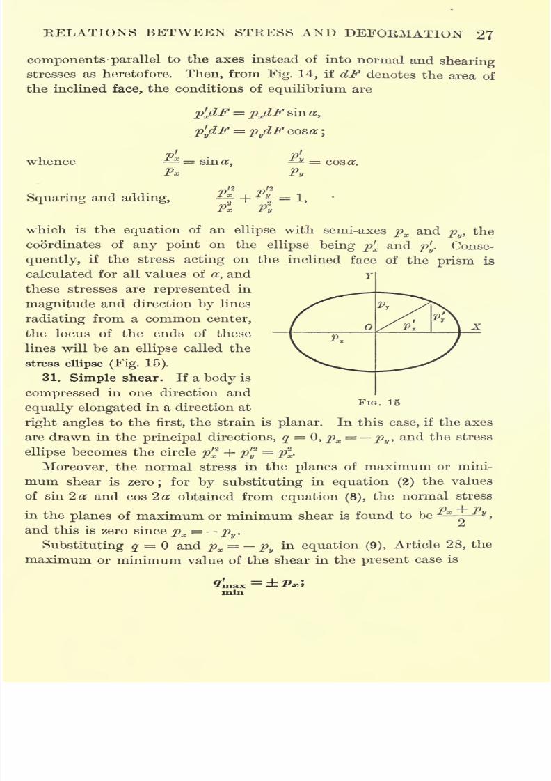
Squaring and adding,K Krf_l
AJ
which is the equation of an ellipse with semi-axes px and py)the
coordinates of any point on theellipse being p
r
x and p'y . Conse-
quently, if the stress acting on the inclined face of the prism is
calculated for all values of a, and
these stresses are represented in
magnitude and direction by lines
radiating from a common center,
the locus of the ends of these
lines will be an ellipse called the
stress ellipse (Fig. 15).
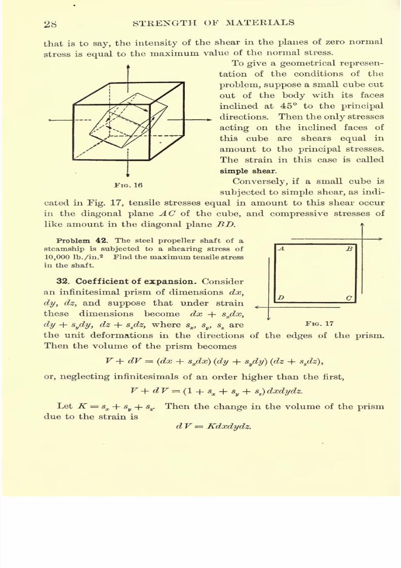
31. Simple shear. If a body is
compressed in one direction and
equally elongated in a direction at
right angles to the first, the strain is planar. In this case, if the axes
are drawn in the principal directions, q=
0, px= py ,
and the stress
ellipse becomes the circle p'2 + p'y
= p2
x.
Moreover, the normal stress in the planes of maximum or mini-
mum shear is zero; for by substituting in equation (2)the values
of sin 2 a and cos 2 a obtained from equation (8), the normal stress
7) ~\~ Din the planes of maximum or minimum shear is found to be **- K
>
and this is zero since px= py
.
Substituting q= and px
= pyin equation (9),
Article 28, the
maximum or minimum value of the shear in the present case is
FIG. 15
[ ruax
miii
7/30/2019 Textbook on Streng 00 Slo Crich
http://slidepdf.com/reader/full/textbook-on-streng-00-slo-crich 70/433
7/30/2019 Textbook on Streng 00 Slo Crich
http://slidepdf.com/reader/full/textbook-on-streng-00-slo-crich 71/433
RELATIONS BETWEEN STRESS AND DEFORMATION 29
For this reason K is called the coefficient of cubical expansion (or
contraction) of the body.
From this definition it is evident that for
temperature stresses thecoefficient of cubical expansion is three times the coefficient of linear
expansion.
From Article 9, for linear tensile strain,
m
Consequently, in this case,
Jf <jX X
-*i- ~ & ~*
m 2
m E
Since the prism is certainly not decreased in volume by a tensile
strain, K cannot be negative and therefore m 2 > 0, or m > 2. If
m =2, K =
0, which means
that the body is incompressi-
ble. Therefore 2 is the lower
limit of Poisson's constant.
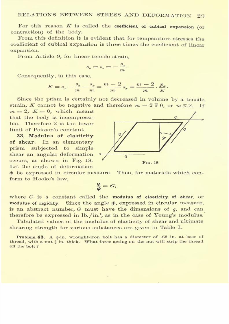
33. Modulus of elasticity
of shear. In an. elementary
prism subjected to simple
shear an angular deformation
occurs, as shown in Fig. 18.FlG lg
Let the angle of deformation
</>be expressed in circular measure. Then, for materials which con-
form to Hooke's law,
7
where G is a constant called the modulus of elasticity of shear, or
modulus of
rigidity.
Since theangle </>, expressed
in circular
measure,is an abstract number, G must have the dimensions of
q,and can
therefore be expressed in lb./in.2
,as in the case of Young's modulus.
Tabulated values of the modulus of elasticity of shear and ultimate
shearing strength for various substances are given in Table I.
Problem 43. Af-in. wrought-iron bolt has a diameter of .62 in. at base of
thread, with a nutf
in. thick. What force acting on the nut will strip the thread
off the bolt ?
7/30/2019 Textbook on Streng 00 Slo Crich
http://slidepdf.com/reader/full/textbook-on-streng-00-slo-crich 72/433
7/30/2019 Textbook on Streng 00 Slo Crich
http://slidepdf.com/reader/full/textbook-on-streng-00-slo-crich 73/433
7/30/2019 Textbook on Streng 00 Slo Crich
http://slidepdf.com/reader/full/textbook-on-streng-00-slo-crich 74/433
7/30/2019 Textbook on Streng 00 Slo Crich
http://slidepdf.com/reader/full/textbook-on-streng-00-slo-crich 75/433
7/30/2019 Textbook on Streng 00 Slo Crich
http://slidepdf.com/reader/full/textbook-on-streng-00-slo-crich 76/433
34 STRENGTH OF MATERIALS
which by equation (11)is equivalent to assuming m = 4. For this
value of m equation (15) becomes
Problem 49. A round steel shaft used for transmitting power bears a trans-
verse load. At the most dangerous section the normal stress due to bending is
5000 lb./in.2
,and the shear due to torsion is 8000 lb./in.
2 Calculate the intensity
of the equivalent stress.
EXERCISES ON CHAPTER II
Problem 50. In a boiler plate the tensile stress in the direction of the axis of
the shell is 2 tons per square inch, and the hoop stress is 4 tons per square inch.
Calculate the equivalent linear tensile stress.
Problem 51. At a point in strained material the principal stresses are 0,
9000 lb./in.2tensile, and 5000 lb./in.
2compressive. Find the intensity and direc-
tion of the resultant stress on a plane inclined 45 to the axis of the tensile stress
and perpendicular to the plane which has no stress.
Problem 52. At a point in the cross section of a girder there is a compressive
stress of 5 tons/in.2 normal to the cross section, and a shearing stress of 3 tons/in.
2
in the plane of the section. Find the directions and amounts of the principal
stresses.
Problem 53. At a certain point in a shaft there is a shearing stress of 5000 lb./in.2
in the plane of the cross section, and a tensile stress of 3000 lb./in.2parallel to the
axis of the shaft. Find the direction and intensity of the maximum shear.
Problem 54. Solve Problem 51 graphically by drawing the stress ellipse to scale
and scaling off the required stress.
Problem 55. In a shaft used for transmitting power the maximum shearing
stress, arising from torsional strain,is 5000
lb./in.
2 Find thenormal,
orbending,
stress it can also carry if the working stress is limited to 10,000 lb./in.2 for tension
or compression, and to 8000 lb./in.2 for shear.
7/30/2019 Textbook on Streng 00 Slo Crich
http://slidepdf.com/reader/full/textbook-on-streng-00-slo-crich 77/433
CHAPTER III
ANALYSIS OF STRESS IN BEAMS
37. System of equivalent forces. The theory of beams deals, in
general,
with the stresses
producedin a
prismatic body bya set of
external forces in static equilibrium. Ordinarily these forces all lie
m one plane ;in this case it is proved in mechanics that they can be
replaced by a single force acting at any given point in this plane,
and a moment. To balance this equivalent system of external forces,
the stresses acting on any cross section of the beam must also consist
of a single force and a moment, the point of application of this single
force being conveniently chosen as the
center of gravity of the cross section.
The following special cases are of fre-
quent occurrence.
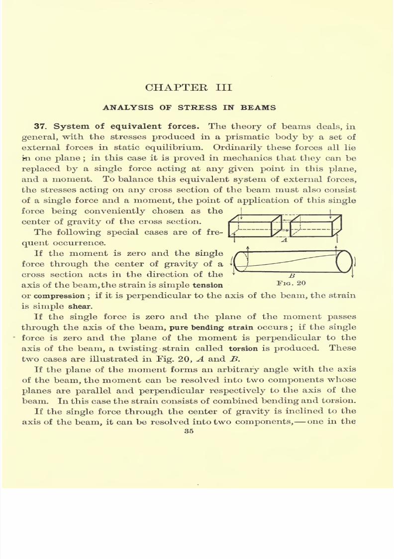
If the moment is zero and the single
force through the center of gravity of a
cross section acts in the direction of the
axis of the beam,the strain is simple tension
or compression ;if it is perpendicular to the axis of the beam, the strain
is simple shear.
If the single force is zero and the plane of the moment passes
through the axis of the beam, pure bending strain occurs;
if the single
force is zero and the plane of the moment is perpendicular to the
axis of the beam, a twisting strain called torsion is produced. These
two cases are illustrated in Fig. 20, A and B.
If the plane of the moment forms an arbitrary angle with the axis
of the beam, the moment can be resolved into two components whose
planes are parallel and perpendicular respectively to the axis of the
beam. In this case the strain consists of combined bending and torsion.
If the single force through the center of gravity is inclined to the
axis of thebeam,
it can be resolved into twocomponents,
one in the
35
7/30/2019 Textbook on Streng 00 Slo Crich
http://slidepdf.com/reader/full/textbook-on-streng-00-slo-crich 78/433
7/30/2019 Textbook on Streng 00 Slo Crich
http://slidepdf.com/reader/full/textbook-on-streng-00-slo-crich 79/433
ANALYSIS OF STRESS IN BEAMS 37
CD.* Between these two there must lie a strip of fibers which are
neither lengthened nor shortened. The horizontal line in which this
stripintersects
anycross section is called the neutral axis of the section.
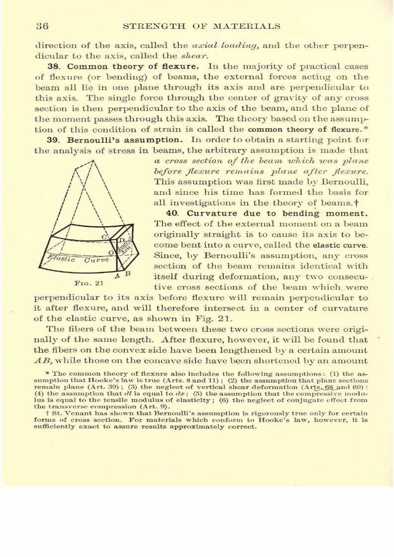
41. Consequence of Bernoulli's assumption. From Fig. 21 it is
evident that, as a consequence of Bernoulli's assumption, the length-
ening or shortening of any longitudinal fiber is proportional to its
distance from the neutral axis. But, by Hooke's law, the stress is
proportional to the deformation produced. Therefore the stress on
any longitudinal fiber is likewise proportional to its distance from
the neutral axis. Navier was the first to deduce this result fromBernoulli's assumption.
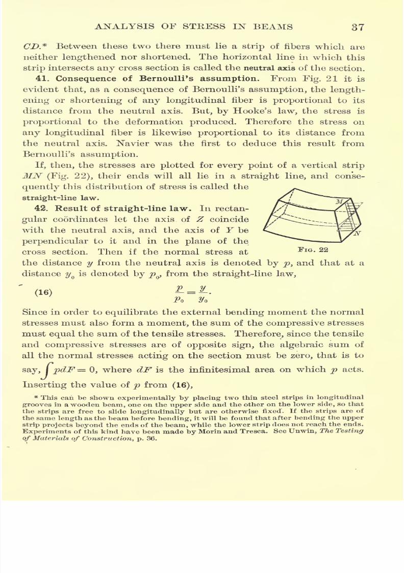
If, then, the stresses are plotted for every point of a vertical strip
MN(Fig. 22), their ends will all lie in a straight line, and conse-
quently this distribution of stress is called the
straight-line law.
42. Result of straight-line law. In rectan-
gular coordinates let the axis of Z coincide
with the neutral axis, and the axis of Y be
perpendicular to it and in the plane of the
cross section. Then if the normal stress atFlG - 22
the distance y from the neutral axis is denoted by p, and that at a
distance yQis denoted by pQ)
from the straight-line law,
'
(16) *=.PO y
Since in order to equilibrate the external bending moment the normal
stresses must also form a moment, the sum of the compressive stresses
must equal the sum of the tensile stresses. Therefore, since the tensile
and compressive stresses are of opposite sign, the algebraic sum of
all the normal stresses acting on the section must be zero, that is to
say, I pdF= 0, where dF is the infinitesimal area on which p acts.
Inserting the value of p from(16),
* This can be shown experimentally by placing two thin steel strips in longitudinal
grooves in a wooden beam, one on the upper side and the other on the lower side, so that
the strips are free to slide longitudinally but are otherwise fixed. If the strips are of
the same length as the beam before bending, it will be found that after bending the upper
strip projects beyond the ends of the beam, while the lower strip does not reach the ends.
Experiments of this kind have been made by Morin and Tresca. See Unwin, The Testing
of Materials of Construction, p. 36.
7/30/2019 Textbook on Streng 00 Slo Crich
http://slidepdf.com/reader/full/textbook-on-streng-00-slo-crich 80/433
38 STRENGTH OF MATERIALS
/Poj
and therefore
/= 0.
But the distance of the center of gravity of the section from the axis
of Z(or
neutral axis) is given by
fydJF-
-fy = a
Therefore, since / yd F = 0, y must be zero, and consequently the
neutral axis passes through the center of gravity of the section.
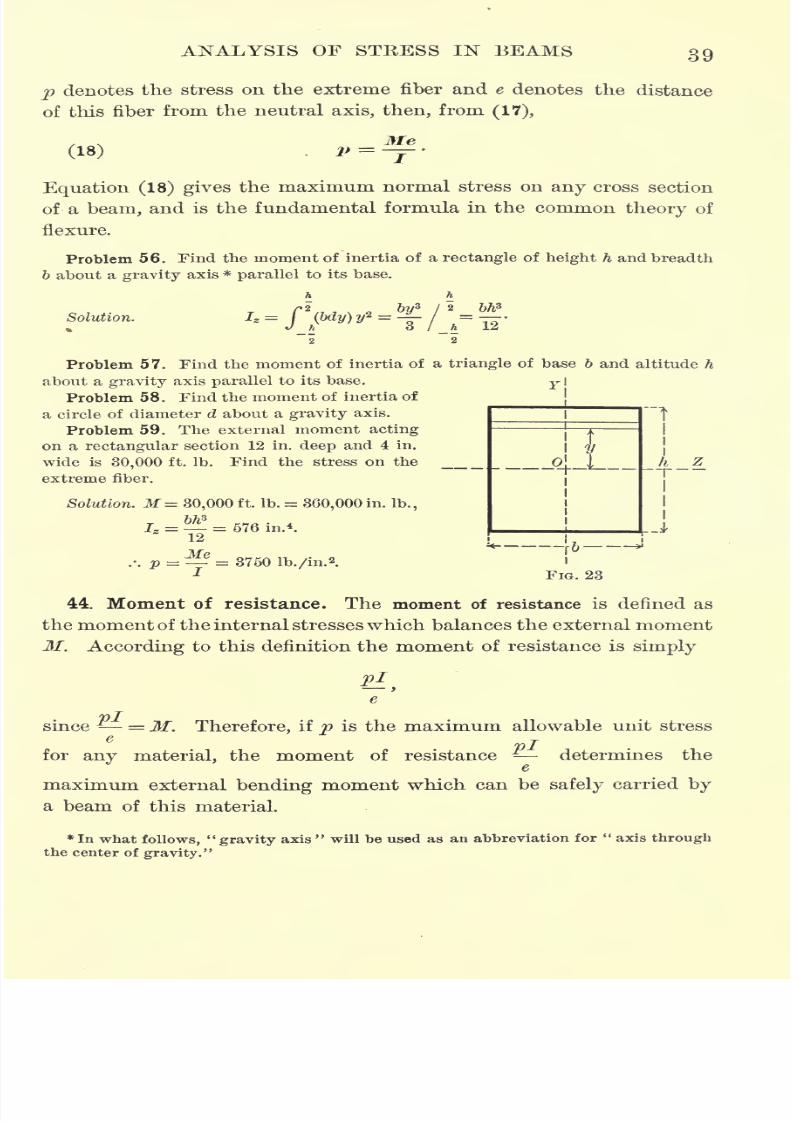
43. Moment of inertia. For equilibrium, the moment of the nor-
mal stresses
acting
on
any
cross section mustequal
the moment of
the external forces at this section. Therefore, if M denotes the
moment of the external forces, or external bending moment, as it is
called,
ipydF = M,
or, from (16),
The integralJy*dF depends only on the form of the cross section,
and is called the moment of inertia of the cross section with respect to
the neutral axis.
Let the moment of inertia be denoted by Z Then
I-
and, consequently,
%o(17) Po
=-J-'
This formula gives the intensity of the normal stressp at the distance
2/ from the neutral axis, due to anexternal
bending moment M.If
7/30/2019 Textbook on Streng 00 Slo Crich
http://slidepdf.com/reader/full/textbook-on-streng-00-slo-crich 81/433
7/30/2019 Textbook on Streng 00 Slo Crich
http://slidepdf.com/reader/full/textbook-on-streng-00-slo-crich 82/433
7/30/2019 Textbook on Streng 00 Slo Crich
http://slidepdf.com/reader/full/textbook-on-streng-00-slo-crich 83/433
7/30/2019 Textbook on Streng 00 Slo Crich
http://slidepdf.com/reader/full/textbook-on-streng-00-slo-crich 84/433
7/30/2019 Textbook on Streng 00 Slo Crich
http://slidepdf.com/reader/full/textbook-on-streng-00-slo-crich 85/433
ANALYSIS OF STRESS IN BEAMS 43
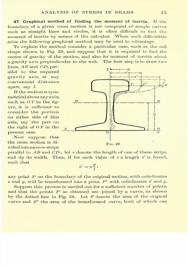
47. Graphical method of finding the moment of inertia. If the
boundary of a given cross section is not composed of simple curves
suchas
straightlines and
circles,it is often difficult to find the
moment of inertia by means of the calculus. When such difficulties
.arise the following graphical method may be used to advantage.
To explain the method consider a particular case, such as the rail
shape shown in Fig. 28, and suppose that it is required to find the
center of gravity of the section, and also its moment of inertia about
a gravity axis perpendicular to the web. The first step is to draw two
lines, AB and CD, par- ,
allel to the required ^ ^ H
gravity axis, at any k|
g"-l*\
convenient distance f *^T T~".
apart, say /.
If the section is sym-
metricalabout any axis,
such as Y in the fig-
ure, it is sufficient to
consider the portion
on either side of this
axis, say the part on
the right of Y in the^
present case.
Now suppose that
the cross section is di-FIG
videdintonarrowstrips
parallel to AB and CD;
let z denote the length of one of these strips,
and dy its width,
such that
Then, if for each value of z a length zr
is found,
any point P on the boundary of the original section, with coordinates
z andy, will be transformed into a point P' with coordinates z
1 and y.
Suppose this process is carried out for a sufficient number of points,
and that the points P' so obtained are joined by a curve, as shown
by the dotted line in Fig. 28. Let F denote the area of the original
curve and F1
the area of the transformed curve, both of which can
7/30/2019 Textbook on Streng 00 Slo Crich
http://slidepdf.com/reader/full/textbook-on-streng-00-slo-crich 86/433
7/30/2019 Textbook on Streng 00 Slo Crich
http://slidepdf.com/reader/full/textbook-on-streng-00-slo-crich 87/433
7/30/2019 Textbook on Streng 00 Slo Crich
http://slidepdf.com/reader/full/textbook-on-streng-00-slo-crich 88/433
7/30/2019 Textbook on Streng 00 Slo Crich
http://slidepdf.com/reader/full/textbook-on-streng-00-slo-crich 89/433
7/30/2019 Textbook on Streng 00 Slo Crich
http://slidepdf.com/reader/full/textbook-on-streng-00-slo-crich 90/433
7/30/2019 Textbook on Streng 00 Slo Crich
http://slidepdf.com/reader/full/textbook-on-streng-00-slo-crich 91/433
7/30/2019 Textbook on Streng 00 Slo Crich
http://slidepdf.com/reader/full/textbook-on-streng-00-slo-crich 92/433
7/30/2019 Textbook on Streng 00 Slo Crich
http://slidepdf.com/reader/full/textbook-on-streng-00-slo-crich 93/433
ANALYSIS OF STKESS IN BEAMS 51
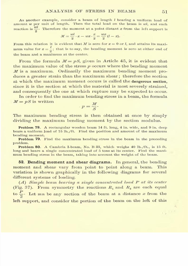
As another example, consider a beam of length I bearing a uniform load of
amount w per unit of length. Then the total load on the beam is wl, and each
reaction is Therefore the moment at a point distant x from the left support is
ivl x wx.,
From this relation it is evident thatM is zero for x = orZ,and attains its maxi-
mum value for x = -;that is to say, the bending moment is zero at either end of
the beam and a maximum at the center.
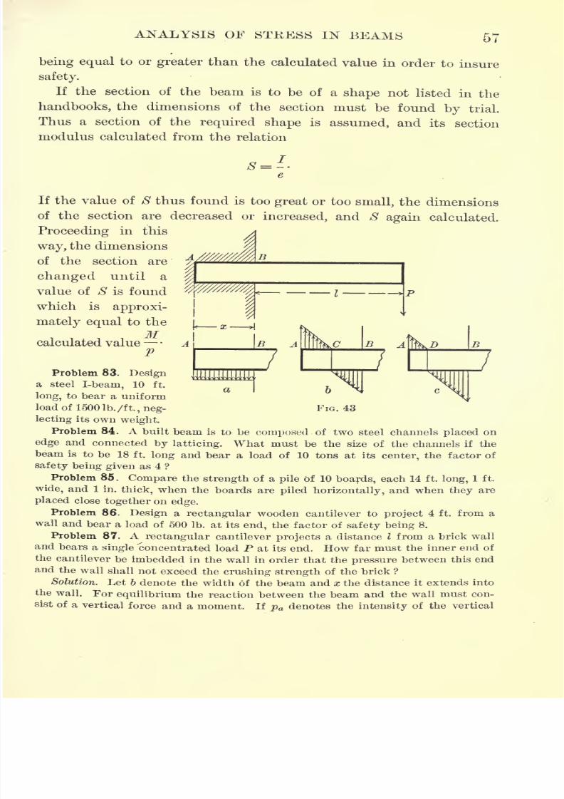
From the formula M=pSy given in Article 45, it is evident that
the maximum value of the stress p occurs where the bending moment
M is a maximum. Ordinarily the maximum bending moment pro-
duces a greater strain than the maximum shear;therefore the section
at which the maximum moment occurs is called the dangerous section,
since it is the section at which the material is most severely strained,
and consequently the one at which rupture may be expected to occur.
In order to find the maximum bending stress in a beam, the formula
M = pS is written
M
The maximum bending stress is then obtained at once by simply
dividing the maximum bending moment by the section modulus.
Problem 78. A rectangular wooden beam 14 ft. long, 4 in. wide, and 9 in. deep
bears a uniform load of 75 Ib./ft. Find the position and amount of the maximum
bending moment.
Problem 79. Find the maximum bending stress in the beam in the preceding
problem.
Problem 80. A Cambria I-beam, No. B 33, which weighs 40 Ib./ft., is 15 ft.
long and bears a single concentrated load of 5 tons at its center. Find the maxi-
mum bending stress in the beam, taking into account the weight of the beam.
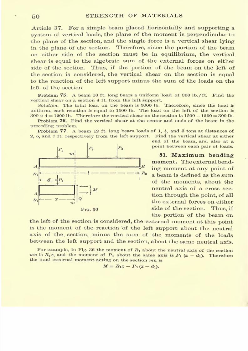
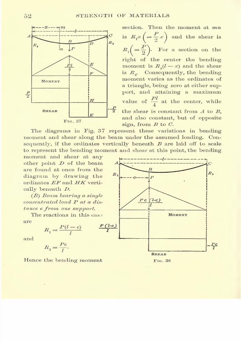
52. Bending moment and shear diagrams. In general, the bending
moment and shear vary from point to point along a beam. This
variation is shown graphically in the following diagrams for several
different systems of loading.
(A) Simple beam bearing a single concentrated load P at its center
(Fig. 37). From symmetry the reactions 7^ and fi2are each equal
-p
to Let mn be any section of the beam at a distance x from the
&
left support, and consider the portion of the beam on the left of this
7/30/2019 Textbook on Streng 00 Slo Crich
http://slidepdf.com/reader/full/textbook-on-streng-00-slo-crich 94/433

7/30/2019 Textbook on Streng 00 Slo Crich
http://slidepdf.com/reader/full/textbook-on-streng-00-slo-crich 95/433
ANALYSIS OF STRESS IN BEAMS 53
at a distance x from the
left support is
provided x < c, and
_Pc(l-
R.
if x > c. If x = c, each of
these moments becomes
Pc(l-c)
and consequently the bend-
ing moment and shear dia-
gramsare as shown in
Fig. 38.
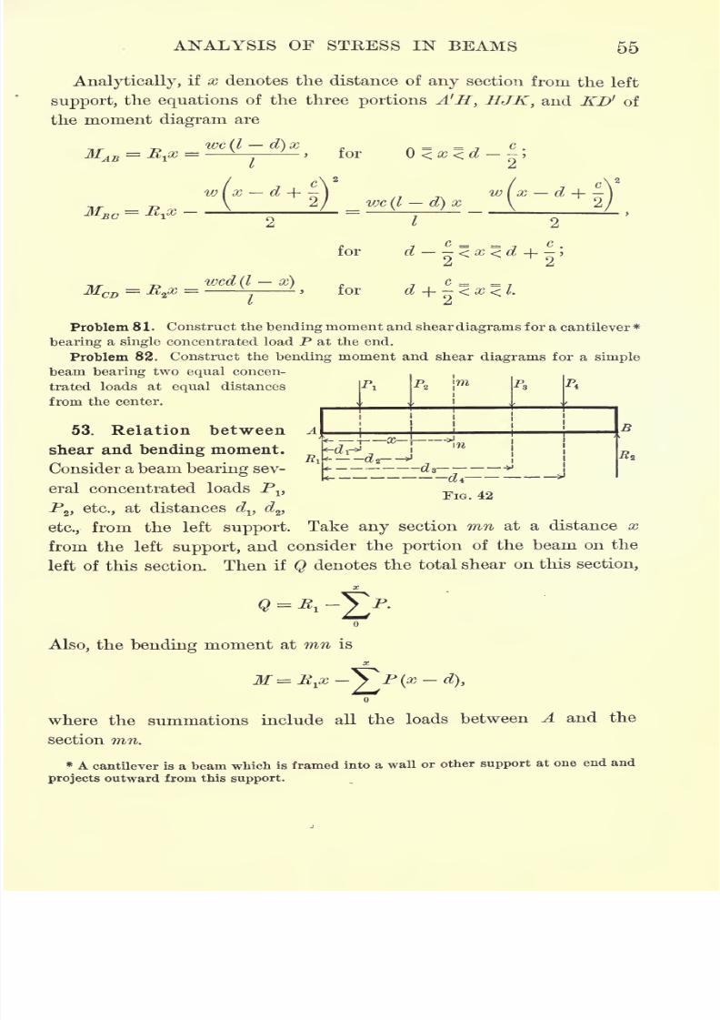
(C) Seam bearing sev-
eral separate loads.
SHEAR
FIG. 30
In this case the bending moment diagram is obtained by con-
structing the diagrams for
each load separately and
thenadding
theirordinates,
as indicated in Fig. 39.
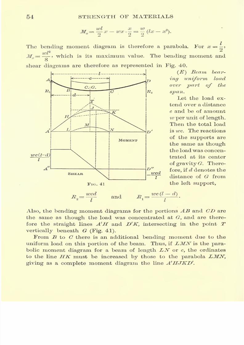
(D) Beam bearing a con-
tinuous uniform load.
Let the load per unit of
length be denoted by w.
Then the total load on the
beam is
wl,and the reac-
tions are
wl
Hence at a distance x from
the left support the bend-
ing moment Mx is
7/30/2019 Textbook on Streng 00 Slo Crich
http://slidepdf.com/reader/full/textbook-on-streng-00-slo-crich 96/433
7/30/2019 Textbook on Streng 00 Slo Crich
http://slidepdf.com/reader/full/textbook-on-streng-00-slo-crich 97/433
ANALYSIS OF STRESS IN BEAMS 55
Analytically, if x denotes the distance of any section from the left
support, the equations of the three portions A'H, HJK, and KD' of
the moment diagram are
-"^AB **jtf>
7/30/2019 Textbook on Streng 00 Slo Crich
http://slidepdf.com/reader/full/textbook-on-streng-00-slo-crich 98/433
7/30/2019 Textbook on Streng 00 Slo Crich
http://slidepdf.com/reader/full/textbook-on-streng-00-slo-crich 99/433
7/30/2019 Textbook on Streng 00 Slo Crich
http://slidepdf.com/reader/full/textbook-on-streng-00-slo-crich 100/433
7/30/2019 Textbook on Streng 00 Slo Crich
http://slidepdf.com/reader/full/textbook-on-streng-00-slo-crich 101/433
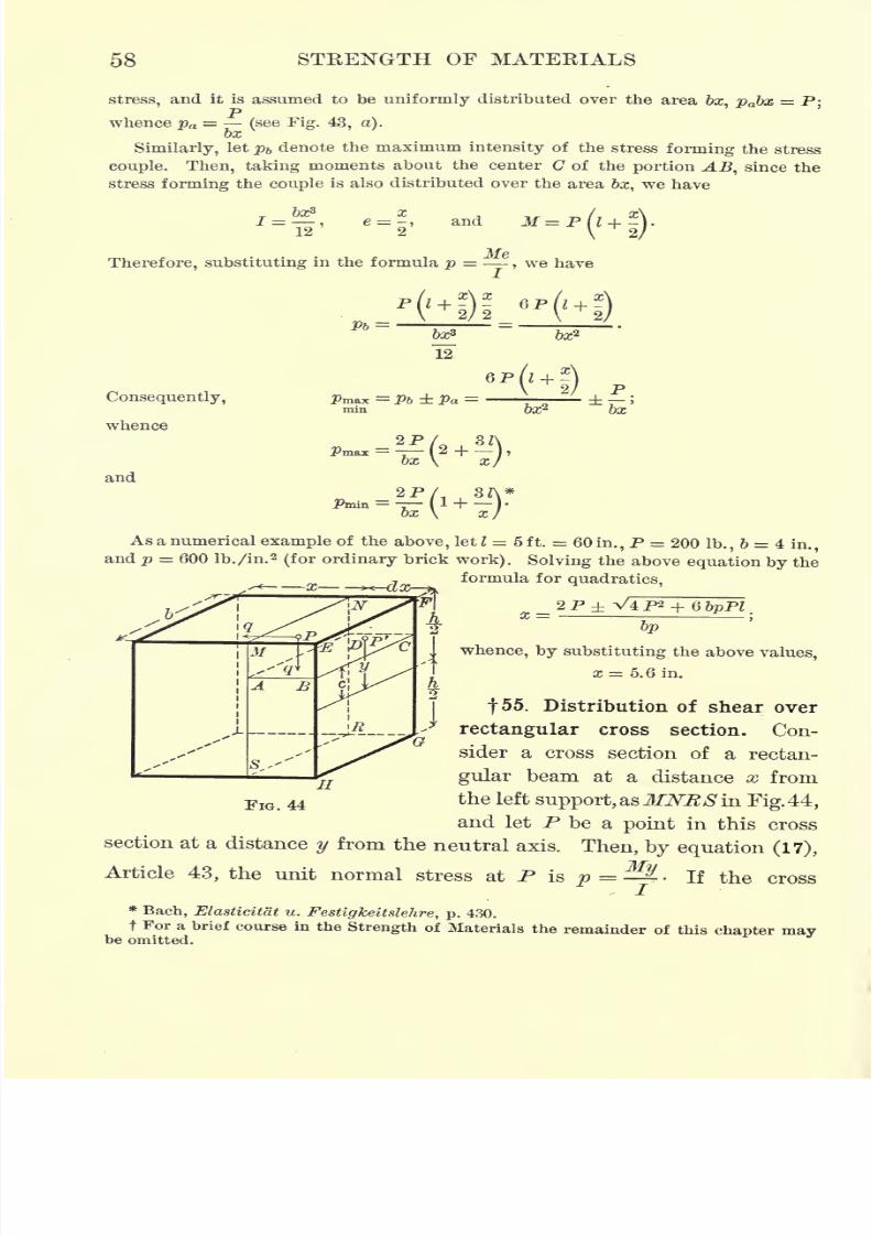
ANALYSIS OF STRESS IN BEAMS 59
section is moved from this position parallel to itself a distance dx,
say to the position EFGH in the figure, the rate of change of p with
respect to x is
/27^ dp _dM y _ y
to dZ I IQ'
The difference between the normal stresses acting on these two
adjacent cross sections tends to shove the point P in a direction
parallel to the axis of the beam, and this tendency is resisted by
a shearing stress of intensity q at P, also parallel to the axis of
the beam. Therefore, since the resultant normal stress on the area*
r 2
BCEF is I dp-dF, and the resultant shearing stress on the area
*) c
ABCD is qbdx, h_
/2dp
- dF = qbdx.
Substituting the value of dp from equation (27),
whence h
(28) q= Q CydF.
Formula (28) applies to any cross section bounded by parallel sides.
In Article 23 it was proved that whenever a shearing stress acts
along any plane in an elastic solid, there is always another shearing
stress of equal intensity acting at the same point in a plane at right
angles to the first. Consequently, formula (28) also gives the intensity
of the stress at any point P in a direction perpendicular to the neutral
axis of the section.
For a rectangular cross section
and hence
(29) i8 a
7/30/2019 Textbook on Streng 00 Slo Crich
http://slidepdf.com/reader/full/textbook-on-streng-00-slo-crich 102/433
60 STKENGTH OF MATEKIALS
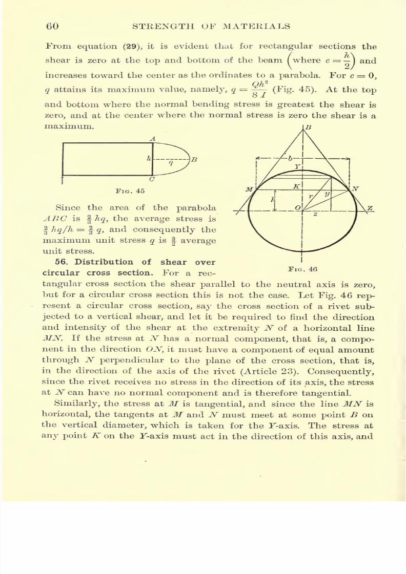
From equation (29),it is evident that for rectangular sections the
shear is zero at the top and bottom of the beam ( where c = -)and
\ 2/
increases toward the center as the ordinates to a parabola. For c = 0,
q attains its maximum value, namely, q= ~-
(Fig. 45). At the top
and bottom where the normal bending stress is greatest the shear is
zero, and at the center where the normal stress is zero the shear is a
maximum.
1
FIG. 45
Since the area of the parabola
ABC is %hq, the average stress is
I hq/h = | q,and consequently the
maximum unit stress q is| average
unit stress.
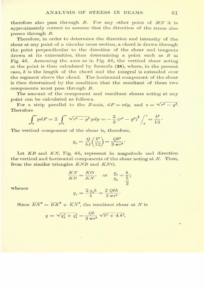
56. Distribution of shear over
circular cross section. For a rec-
tangular cross section the shear parallel to the neutral axis is zero,
but for a circular cross section this is not the case. Let Fig. 46 rep-
resent a circular cross section, say the cross section of a rivet sub-
jected to a vertical shear, and let it be required to find the direction
and intensity of the shear at the extremity N of a horizontal line
MN. If the stress at N has a normal component, that is, a compo-
nent in the direction ON, it must have a component of equal amount
through N perpendicular to the plane of the cross section, that is,
in the direction of the axis of the rivet (Article 23). Consequently,
since the rivet receives no stress in the direction of its axis, the stress
at N can have no normal component and is therefore tangential.
Similarly, the stress at M is tangential, and since the line MN is
horizontal, the tangents at M and N must meet at some point B on
the vertical diameter, which is taken for the F-axis. The stress at
any point K on the F-axis must act in the direction of this axis, and
7/30/2019 Textbook on Streng 00 Slo Crich
http://slidepdf.com/reader/full/textbook-on-streng-00-slo-crich 103/433
7/30/2019 Textbook on Streng 00 Slo Crich
http://slidepdf.com/reader/full/textbook-on-streng-00-slo-crich 104/433
62 STRENGTH OF MATERIALS
or, since - + A2
In this equation q is proportional to 5, and hence the maximum
value of q is at the center where b = 2 r. Hence
(/max=
E
FIG. 47
The maximum unit shear on a circular cross section is therefore
equal to of its average value.
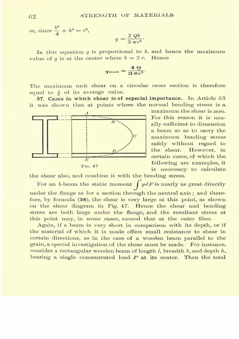
57. Cases in which shear is of especial importance. In Article 53
it was shown that at points where the normal bending stress is a
j_maximum the shear is zero.
For this reason it is usu-
ally sufficient to dimension
a beam so as to
carry
the
maximum bending stress
safely without regard to
the shear. However, in
certain cases, of which the
following are examples, it
is necessary to calculate
the shearalso,
and combine it with the
bendingstress.
For an I-beam the static moment / ydF is nearly as great directly
under the flange as for a section through the neutral axis;and there-
fore, by formula (28), the shear is very large at this point, as shown
on the shear diagram in Fig. 47. Hence the shear and bending
stress are both large under the flange, and the resultant stress at
this point may, in some cases, exceed that at the outer fiber.
Again, if a beam is very short in comparison with its depth, or if
the material of which it is made offers small resistance to shear in
certain directions, as in the case of a wooden beam parallel to the
grain, a special investigation of the shear must be made. For instance,
consider a rectangular wooden beam of length /,breadth I, and depth h,
bearing a single concentrated load P at its center. Then the total
7/30/2019 Textbook on Streng 00 Slo Crich
http://slidepdf.com/reader/full/textbook-on-streng-00-slo-crich 105/433
ANALYSIS OF STRESS IN BEAMS 63
shear on any section is > and the maximum bending moment is --2 4
Hence the maximum unit normal stress is
3 PI^ _P ~'~
I'
2
~2
P C zbli*
Also, since Q = and / ydF = > the maximum unit shear is
2 Jo 8
j. Cy*V=**.IIJ
"46fc
Now let /c denote the ratio between the tensile strength in the direc-
tion of the fiber and the shearing strength parallel to the fiber.
Then, in order that the beam shall be equally safe against normal
and shearing stress, p = tcq,or
3PZ_ 3JP.
whence
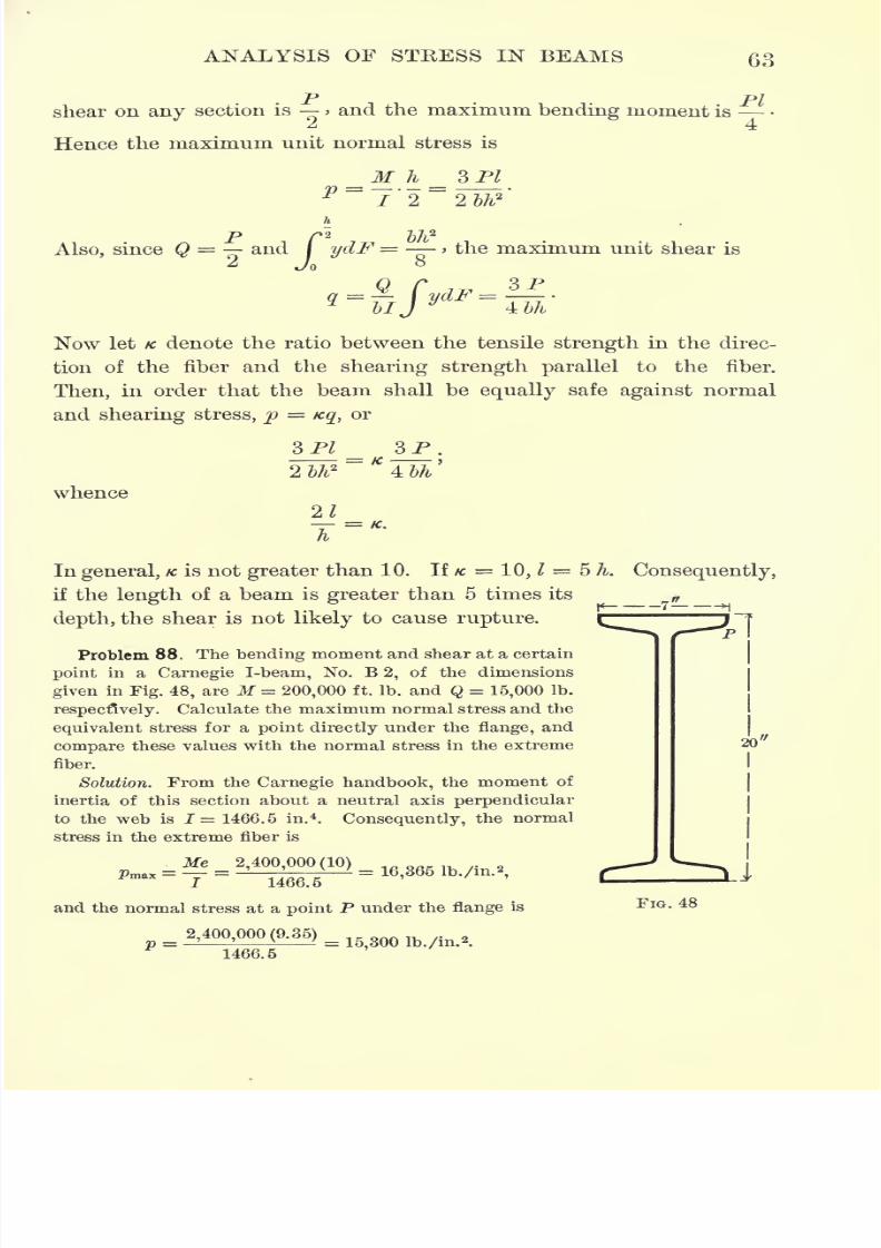
FIG. 48
20'
In general, K is not greater than 10. If /c = 10, 1 = 5 h. Consequently,
if the length of a beam is greater than 5 times its
depth, the shear is not likely to cause rupture. ^~~ ^i ~J
Problem 88. The bending moment and shear at a certain
point in a Carnegie I-beam, No. B 2, of the dimensions
given in Fig. 48, are M= 200,000 ft. Ib. and Q = 15,000 Ib.
respectively. Calculate the maximum normal stress and the
equivalent stress for a point directly under the flange, and
compare these values with the normal stress in the extreme
fiber.
Solution. From the Carnegie handbook, the moment of
inertia of this section about a neutral axis perpendicular
to the web is I = 1466.5 in.4
.
Consequently, the normalstress in the extreme fiber is
Me 2,400,000(10)
I 1466.5
and the normal stress at a point P under the flange is
2,400,000(9.35) =1466.5
7/30/2019 Textbook on Streng 00 Slo Crich
http://slidepdf.com/reader/full/textbook-on-streng-00-slo-crich 106/433
7/30/2019 Textbook on Streng 00 Slo Crich
http://slidepdf.com/reader/full/textbook-on-streng-00-slo-crich 107/433
ANALYSIS OF STRESS IN BEAMS 65
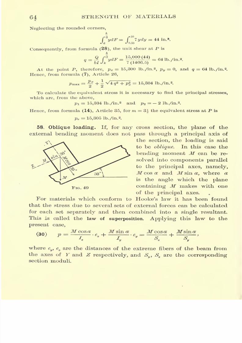
Problem 89. In an inclined railway the angle of inclination with the horizontal
is 30. The stringers are 10 ft. 6 in. apart, inside measurement, and the rails are
placed 1 ft. inside the stringers. The ties are 8 in. deep and 6 in. wide, and the
maximum load transmitted by each rail to one tie is 10 tons. Calculate the maxi-
mum normal stress in the tie.
Solution. The bending moment is the same for all points of the tie between the
rails, and is 20,000 ft. Ib. From Problem 66, Sz= 64 in. 3 and Sy
= 48 in. 8. There-
fore, from equation (30),
240,000 (\ 240,000 (-\
- 5744
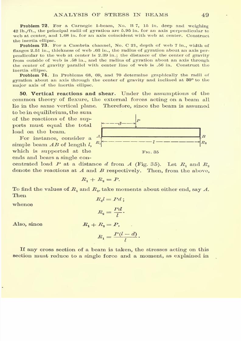
59. Eccentric loading. If the external forces acting on any cross
section reduce to a single force P, perpendicular to the plane of the
section, but not passing through its center of gravity, this force is
called an eccentric load. Let B denote the point of application of the
eccentric load P, and let y'z1
denote the coordinates of B. Then the
eccentric force P acting at B can be replaced by an equal and parallel
force acting at the center of gravity C of the section, and a moment
whose plane is perpendicular to the-, section. This moment can then
be resolved into two components parallel to the principal axes, of
amounts Py' and Pz' respectively. Therefore, by the law of super-
position, the intensity of the stress at any point (y, z)of the cross
section is
P Pzf
Py'P = F
+^'
Z +^ y '
or, since I= Ftf,
At the neutral axis the stfSs^s zero, and consequently 1 H- + ~-
*y*
must be zero; or, since the semi-axes of the inertia ellipse are a = t
y
and b = tgt
this condition becomes
(3D
P
+
g-'-.
.
This condition must be satisfied by every point on the neutral axis,
and is therefore the equation of the neutral axis. To each pair of values
of y' and z', that is, to each position of the point of application B of
the eccentric load, there corresponds one and only one position of the
neutral axis.
7/30/2019 Textbook on Streng 00 Slo Crich
http://slidepdf.com/reader/full/textbook-on-streng-00-slo-crich 108/433
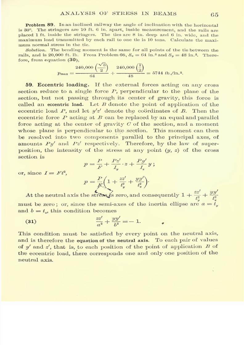
66 STRENGTH OF MATERIALS
z2
ifIf the point B lies on the ellipse + 7^
=1, its coordinates must
or lr
satisfy this equation, and, consequently,
(32) ^ + ^= I-
In this case the neutral axis passes through a point on the ellipse
diametrically opposite to B;for if z', y' are substituted for y
and z in equation (31), it is evident that the condition (32) is satisfied.
z2
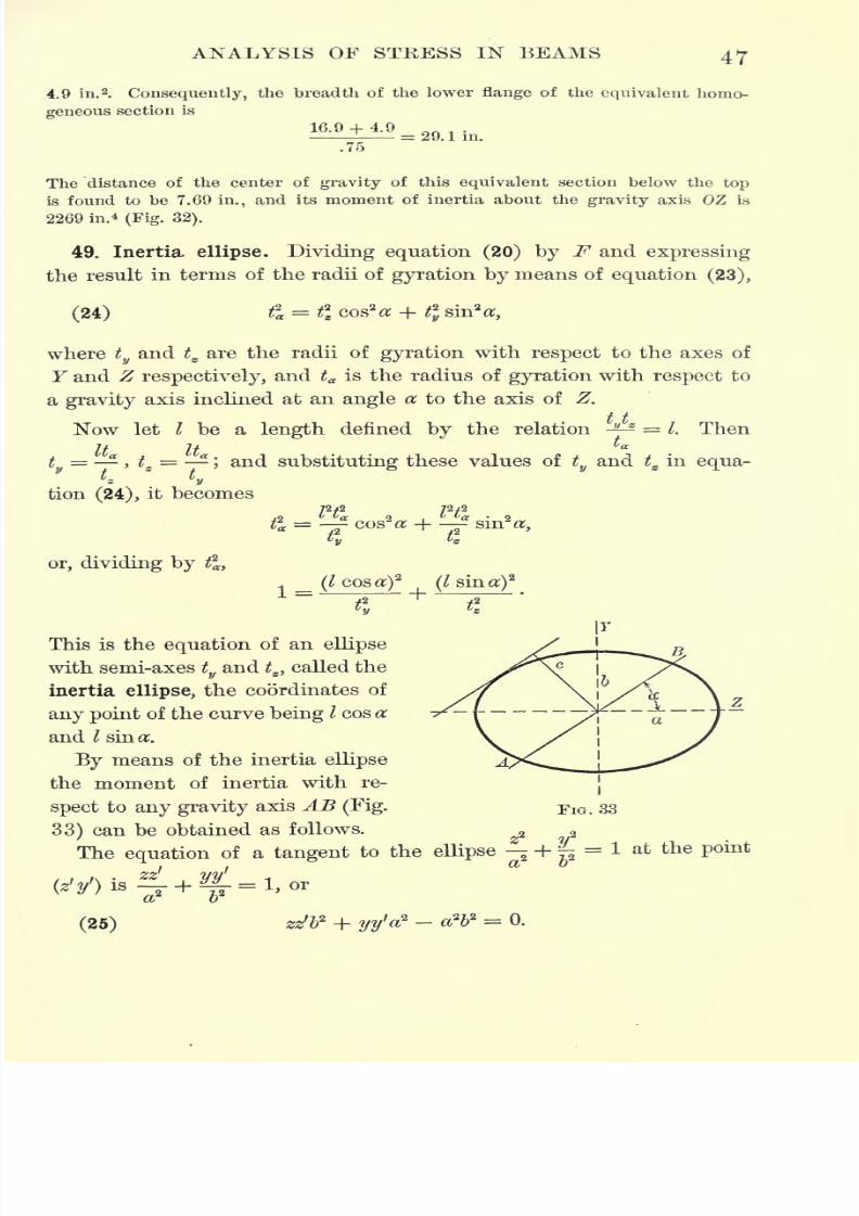
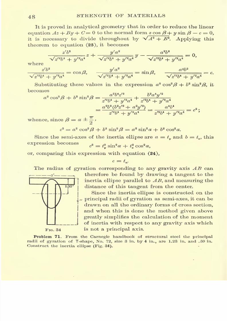
ifThe tangent to the ellipse -f- ^
= 1 at the point z1
, y' is
tyd ?/7/
+ ^- = 1, which is identical with equation (31). Consequently,
if B lies on the inertia ellipse, the neutral axis corresponding to B is
tangent to the ellipse at the point diametrically opposite to B.
From equation (31), the slope of the tan-
gent is found to be
If, then, the point B moves out along a radius
CB, z' and y' increase in the same ratio, and
consequently the slope is constant;that is to
say, if B moves out along a radius, the neu-
tral axis moves parallel to itself.
As zr
and yf
increase, z and y must de-
crease, for theproducts
zzf
andyy
f must be
constant in order to satisfy equation (31).
Therefore the farther B is from the center of
gravity, the nearer the corresponding neutral axis is to the center
of gravity, and vice versa.
If, in Fig. 50, TN is the neutral axis corresponding to B, it fol-
lows, from the above, that CB CT is a constant wherever B is on the
line BT. But if B lies on theellipse,
thecorresponding
neutral axis
is tangent to the ellipse at the point diametrically opposite to B, and
in this case the above product becomes CM2
. Therefore
(33) CB.CT
FIG. 50
From this relation, the position of the neutral axis can be determined
when the position of the point B is given.
7/30/2019 Textbook on Streng 00 Slo Crich
http://slidepdf.com/reader/full/textbook-on-streng-00-slo-crich 109/433
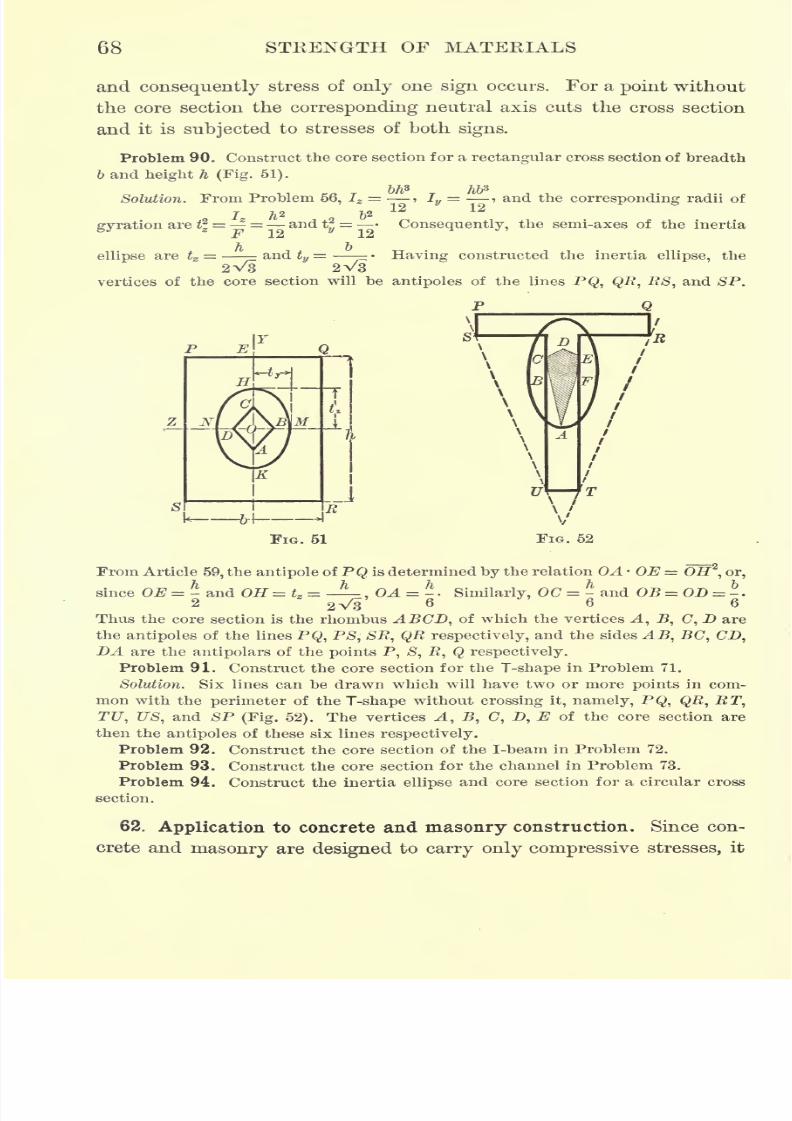
7/30/2019 Textbook on Streng 00 Slo Crich
http://slidepdf.com/reader/full/textbook-on-streng-00-slo-crich 110/433
68 STEENGTH OF MATERIALS
and consequently stress of only one sign occurs. For a point without
the core section the corresponding neutral axis cuts the cross section
and it is subjected to stresses of both signs.
Problem 90. Construct the core section for a rectangular cross section of breadth
b and height h (Fig. 51).
Solution. From Problem 56, Iz = > Iy= and the corresponding radii of
12
gyration are % = =andt^
=F 12 12
ellipse are tg=
h band tv
= '
2V3\/3
Consequently, the semi-axes of the inertia
Having constructed the inertia ellipse, the
vertices of the core section will be antipoles of the lines PQ, QR, RS, and SP.
P Q
From Article 59, the antipole of PQ is determined by the relation OA OE = Off2
, or,
since OE=- and OH=te = -^ ,OA = -. Similarly, OC = - and OB = OD = -.2 2 V3 6
66hus the core section is the rhombus ABCD, of which the vertices A, B, C, D are
the antipoles of the lines PQ, PS, SR, QR respectively, and the sides AB, BC, CD,DA are the antipolars of the points P, S, R, Q respectively.
Problem 91. Construct the core section for the T-shape in Problem 71.
Solution. Six lines can be drawn which will have two or more points in com-
mon with the perimeter of the T-shape without crossing it, namely, PQ, QR, RT,
TU, US, and SP (Fig. 52). The vertices A, B, C, D, E of the core section are
then the antipoles of these six lines respectively.Problem 92. Construct the core section of the I-beam in Problem 72.
Problem 93. Construct the core section for the channel in Problem 73.
Problem 94. Construct the inertia ellipse and core section for a circular cross
section.
62. Application to concrete and masonry construction. Since con-
crete and masonry are designed to carry only compressive stresses, it
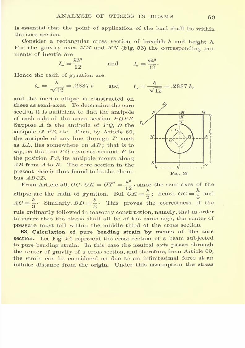
7/30/2019 Textbook on Streng 00 Slo Crich
http://slidepdf.com/reader/full/textbook-on-streng-00-slo-crich 111/433
ANALYSIS OF STRESS IN BEAMS 69
is essential that the point of application of the load shall lie within
the core section.
Consider a rectangular cross section of breadth ~b and height h.
For the gravity axes MM and NN (Fig. 53) the corresponding mo-
ments of inertia are
I =m~
12
Hence the radii of gyration are
b
Vl2
= .28875
Aand
and = ^ = .2887^,
Vl2and the inertia ellipse is constructed on
these as semi-axes. To determine the core
section it is sufficient to find the antipole
of each side of the cross section PQRS.
Suppose A is the antipole of PQ, B the
antipole of PS, etc. Then, by Article 60,
the antipole of any line through P, such
as LL, lies somewhere on AB;that is to
say, as the line PQ revolves around P to
the position PS, its antipole moves along
AB from A to B. The core section in the
present case is thus found to be the rhom-
bus ABCD.
From Article 59, OC> OK = OT2 = , since the semi-axes of the
7 -L
ellipse are the radii of gyration. But OK=-\ hence OC = - and7 7 2i D
AC = -Similarly, BD = - - This proves the correctness of the
o o
rule ordinarily followed in masonry construction, namely, that in order
to insure that the stress shall all be of the same sign, the center of
pressure must fall within the middle third of the cross section.
63. Calculation of pure bending strain by means of the core
section. Let Fig. 54 represent the cross section of a beam subjected
to pure bending strain. In this case the neutral axis passes through
the center of gravity of a cross section, and therefore, from Article 60,
the strain can be considered as due to an infinitesimal force at an
infinite distance from the origin. Under this assumption the stress
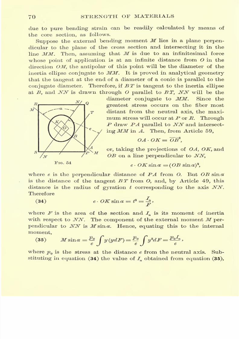
7/30/2019 Textbook on Streng 00 Slo Crich
http://slidepdf.com/reader/full/textbook-on-streng-00-slo-crich 112/433
TO STRENGTH OF MATERIALS
due to pure bending strain can be readily calculated by means of
the core section, as follows.
Suppose
the external bending moment M lies in a plane perpen-
dicular to the plane of the cross section and intersecting it in the
line MM. Then, assuming that M is due to an infinitesimal force
whose point of application is at an infinite distance from in the
direction OM, the antipolar of this point will be the diameter of the
inertia ellipse conjugate to MM. It is proved in analytical geometry
that the tangent at the end of a diameter of a conic is parallel to the
conjugate
diameter. Therefore, if BT is
tangent
to the inertia ellipse
at B, and NN is drawn through parallel to BT, NN will be the
diameter conjugate to MM. Since the
greatest stress occurs on the fiber most
distant from the neutral axis, the maxi-
mum stress will occur at P or E. Through
P draw PA parallel to NN and intersect-
ing
JOf in A.
Then,from Article
59,
R
s
/N
or, taking the projections of OA, OK, and
OB on a line perpendicular to NN,
FIG. 54e OKsma = (OB
where e is the perpendicular distance of PA from 0. But OB sin a
is the distance of the tangent BT from 0, and, by Article 49, this
distance is the radius of gyration t corresponding to the axis NN.
Therefore
(34) e- OKsma = ^ = -2,
where F is the area of the section and In
is its moment of inertia
with respect to NN. The component of the external moment M per-
pendicular to NN is M since. Hence, equating this to the internal
moment,
(35) Msma=^ Cy(ydF) =^ Cy*dF =^,e J e J e
where p is the stress at the distance e from the neutral axis. Sub-
stituting in equation (34) the value of Inobtained from equation (35),
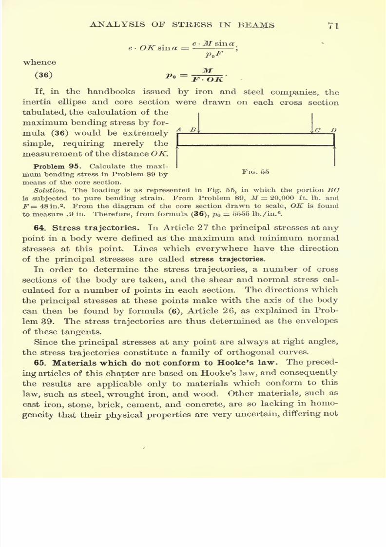
7/30/2019 Textbook on Streng 00 Slo Crich
http://slidepdf.com/reader/full/textbook-on-streng-00-slo-crich 113/433
ANALYSIS OF STRESS IN BEAMS 71
e-M siner
whence
(36)
If, in the handbooks issued by iron and steel companies, the
inertia ellipse and core section were drawn on each cross section
tabulated, the calculation of the
maximum bending stress by for-
mula (36) would be extremelyA B ^ ^ D
simple, requiring merely the
measurement of the distance OK.
Problem 95. Calculate the maxi-
mum bending stress in Problem 89 by
means of the core section.
Solution. The loading is as represented in Fig. 56, in which the portion BC
is subjected to pure bending strain. From Problem 89, M = 20,000 ft. Ib. and
F = 48 in.2
. From the diagram of the core section drawn to scale, OK is found
to measure .9 in. Therefore, from formula (36), pQ = 6555 lb./in.
2.
64. Stress trajectories. In Article 27 the principal stresses at any
point in a body were denned as the maximum and minimum normal
stresses at this point. Lines which everywhere have the direction
of the principal stresses are called stress trajectories.
In order to determine the stress trajectories, a number of cross
sections of the body are taken, and the shear and normal stress cal-
culated for a number of points in each section. The directions which
the principal stresses at these points make with the axis of the body
can then be found by formula (6), Article 26, as explained in Prob-
lem 39. The stress trajectories are thus determined as the envelopes
of these tangents.
Since the principal stresses at any point are always at right angles,
the stress trajectories constitute a family of orthogonal curves.
65. Materials which do not conform to Hooke's law. The preced-
ing articles of this chapter are based on Hooke's law, and consequently
the results are applicable only to materials which conform to this
law, such as steel, wrought iron, and wood. Other materials, such as
cast iron, stone, brick, cement, and concrete, are so lacking in homo-
geneity that their physical properties are very uncertain, differing not
7/30/2019 Textbook on Streng 00 Slo Crich
http://slidepdf.com/reader/full/textbook-on-streng-00-slo-crich 114/433
72 STRENGTH OF MATERIALS
only for different specimens of the material but also for different por-
tions of the same specimen. For this reason it is impossible to apply
to such materials a general method of analysis with any assurance
that the results will approximate the actual behavior of the material.
For practical purposes, however, the best method is to calculate the
strength of such materials by the formulas deduced above, and then
modify the result by a factor of safety so large as to include all
probable exceptions.
The behavior of cast iron is more uncertain than that of any other
material of construction, and it must therefore be used with a larger
factor of safety. If two pieces from the same specimen are subjected
to tensile strain and to cross-bending strain respectively, it will be
found that the ultimate strength deduced from the cross-bending
test is about twice as great as that deduced from the tensile test.
The reason for this is that the neutral axis does not pass through
the center of gravity of a cross section, lying nearer the compression
than the tension side, and also because the stresses increase more
slowly than their distances from the neutral axis. If, then, it becomes
necessary to design a cast-iron beam, the ultimate tensile strength
used in the calculation should be that deduced from bending tests.
For materials such as concrete, stone, and cement, the most
rational method of procedure is to introduce a correction coefficient
77in formula (18) and put
Me
p = r\
where it has been found by experiment that for granite 77=
.96, for
sandstonerj=
.84, and for concrete77= .97.*
66. Design of reenforced concrete beams. Since concrete is a mate-
rial which does not conform to Hooke's law, and moreover does not
obey the same elastic law for tension as for compression, the exact
analysis
of stress in aplain
or reenforced concrete beam would be
much more complicated than that obtained under the assumptions of
the common theory of flexure. The physical properties of concrete,
however, depend so largely on the quality of material and workman-
ship, that for practical purposes the conditions do not warrant a rig-
orous analysis. The following simple formulas, although based on
*Foppl, Festigkeitslehre, p. 144.
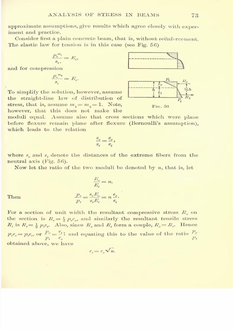
7/30/2019 Textbook on Streng 00 Slo Crich
http://slidepdf.com/reader/full/textbook-on-streng-00-slo-crich 115/433
ANALYSIS OF STRESS IN BEAMS 73
approximate assumptions, give results which agree closely with exper-
iment and practice.
Consider first a plain concrete beam, that is, without reenforcement.
The elastic law for tension is in this case(see Fig. 56)
and for compression
To simplify the solution, however, assume
the straight-line law of distribution of
stress, that is, assume mx
= m2
1. Note,
however, that this does not make the
moduli equal. Assume also that cross sections which were plane
before flexure remain plane after flexure (Bernoulli's assumption),
which leads to the relation
where ecand e
tdenote the distances of the extreme fibers from the
neutral axis(Fig. 56).
Now let the ratio of the two moduli be denoted by n, that is, let
A.
Then
Pt
For a section of unit width the resultant compressive stress Rcon
the section is Rc= \pcec ,and similarly the resultant tensile stress
Rtis E
t
= ^p te
t. Also, since R
cand R
tform a couple, Rc
= Rt. Hence
*Y)>
*Y)
pcec= p t
e( ,or *- = -*; and equating this to the value of the ratio -
Pt ec Pt
obtained above, we have
e.= e.'vn.
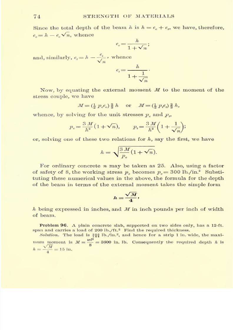
7/30/2019 Textbook on Streng 00 Slo Crich
http://slidepdf.com/reader/full/textbook-on-streng-00-slo-crich 116/433
74 STRENGTH OF MATERIALS
Since the total depth of the beam h is h = ec + e
t)we have, therefore,
ec= h e
c^n, whence
he..=
and, similarly, et=h -
-j=>whence
Now, by equating the external moment M to the moment of the
stress couple, we have
whence, by solving for the unit stresses pcand p t,
e
ii
or, solving one of these two relations for A, say the first, we have
A to1+ v^).M r>~
For ordinary concrete n may be taken as 25. Also, using a factor
of safety of 8, the working stress pc becomes pc= 300 lb./in.
2
Substi-
tuting these numerical values in the above, the formula for the depth
of the beam in terms of the external moment takes the simple form
VM
h being expressed in inches, and M in inch pounds per inch of width
ofbeam.
Problem 96. A plain concrete slab, supported on two sides only, has a 12-ft.
span and carries a load of 200 lb./ft.2 Find the required thickness.
Solution. The load is fff lb./in.2,and hence for a strip 1 in. wide, the maxi-
mum moment is M = = 3600 in. Ib. Consequently the required depth h is
h = = 15 in.
4
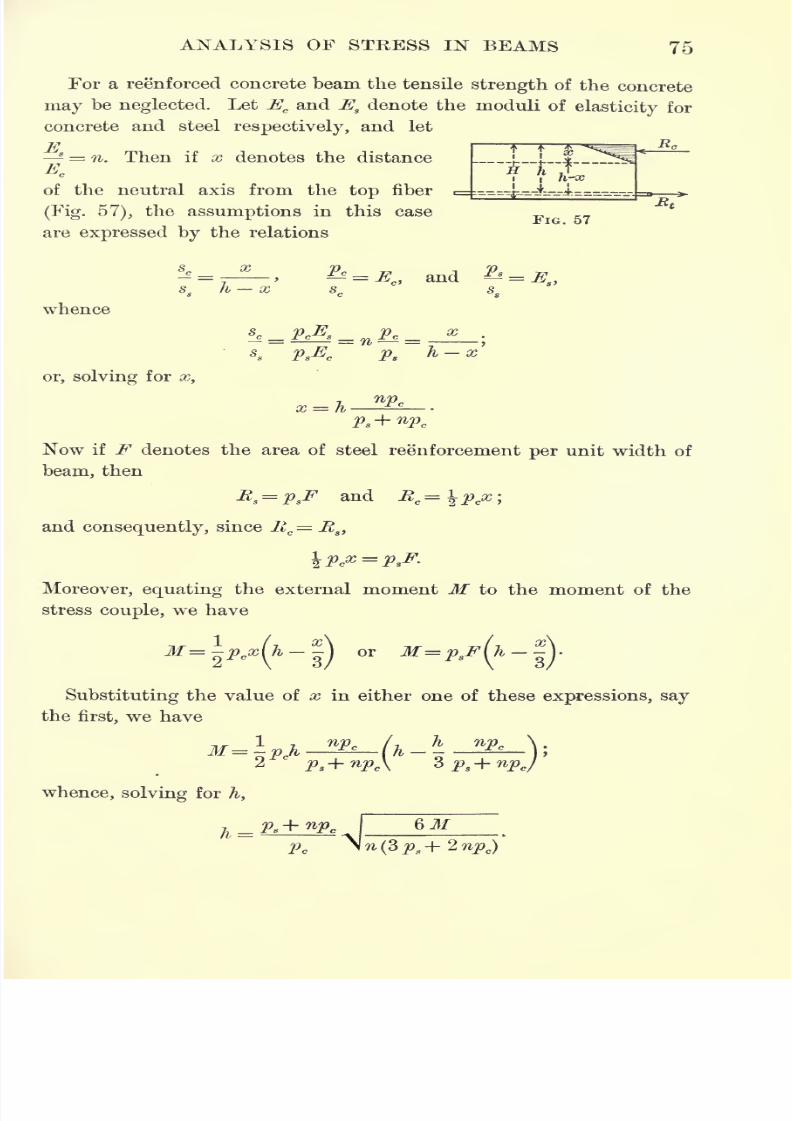
7/30/2019 Textbook on Streng 00 Slo Crich
http://slidepdf.com/reader/full/textbook-on-streng-00-slo-crich 117/433
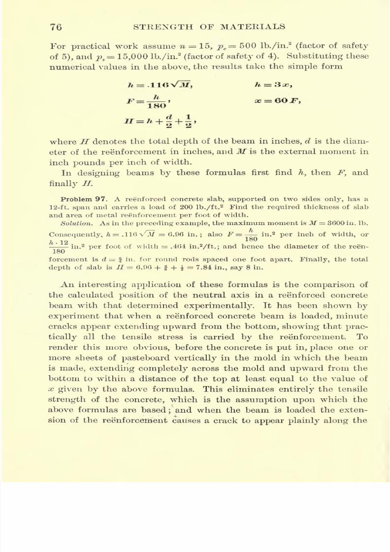
7/30/2019 Textbook on Streng 00 Slo Crich
http://slidepdf.com/reader/full/textbook-on-streng-00-slo-crich 118/433
76 STRENGTH OF MATERIALS
For practical work assume n = 15, pc= 500 lb./in.
2
(factor of safety
of 5), and ps= 15,000 lb./in.
2
(factor of safety of4). Substituting these
numerical values in the above, the results take the simple form
where Hdenotes the total
depthof the beam in
inches,d is the diam-
eter of the reenforcement in inches, and M is the external moment in
inch pounds per inch of width.
In designing beams by these formulas first find h, then F, and
finally H.
Problem 97. A reenforced concrete slab, supported on two sides only, has a
12-ft. span and carries a load of 200 lb./ft.2 Find the required thickness of slab
and areaof
metal reinforcement perfoot of width.
Solution. As in the preceding example, the maximum moment isM = 3600 in. Ib.
Consequently, h= .116 V^7 = 6.96 in.; also F =''
in.2per inch of width, or
in.2per foot of widtli = .464 in.
2/ft.; and hence the diameter of the reen-
180
forcement is d = f in. for round rods spaced one foot apart. Finally, the total
depth of slab is II 6.96 + f + = 7.84 in., say 8 in.
An interesting application of these formulas is the comparison of
the calculated position of the neutral axis in a reenforced concrete
beam with that determined experimentally. It has been shown by
experiment that when a reenforced concrete beam is loaded, minute
cracks appear extending upward from the bottom, showing that prac-
tically all the tensile stress is carried by the reinforcement. To
render this more obvious, before the concrete is put in, place one or
more sheets of pasteboard vertically in the mold in which the beam
is made, extending completely across the mold and upward from the
bottom to within a distance of the top at least equal to the value of
x given by the above formulas. This eliminates entirely the tensile
strength of the concrete, which is the assumption upon which the
above formulas are based; and when the beam is loaded the exten-
sion of the reenforcetrient causes a crack to appear plainly along the
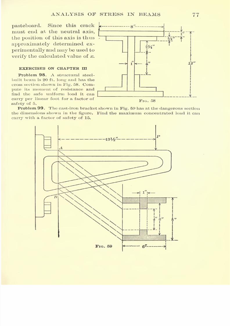
7/30/2019 Textbook on Streng 00 Slo Crich
http://slidepdf.com/reader/full/textbook-on-streng-00-slo-crich 119/433
ANALYSIS OF STRESS IN BEAMS 77
pasteboard. Since this crack
must end at the neutral axis,
the position of this axis is thus
approximately determined ex-
perimentally and maybe used to
verify the calculated value of x.
EXERCISES ON CHAPTER III
Problem 98. A structural steel-
built beam is 20 ft. long and has the
cross section shown in Fig. 58. Com-pute its moment of resistance and
find the safe uniform load it can
carry per linear foot for a factor of
safety of 5.
Problem 99. The cast-iron bracket shown in Fig. 59 has at the dangerous section
the dimensions shown in the figure; Find the maximum concentrated load it can
carry with a factor of safety of 15.
1
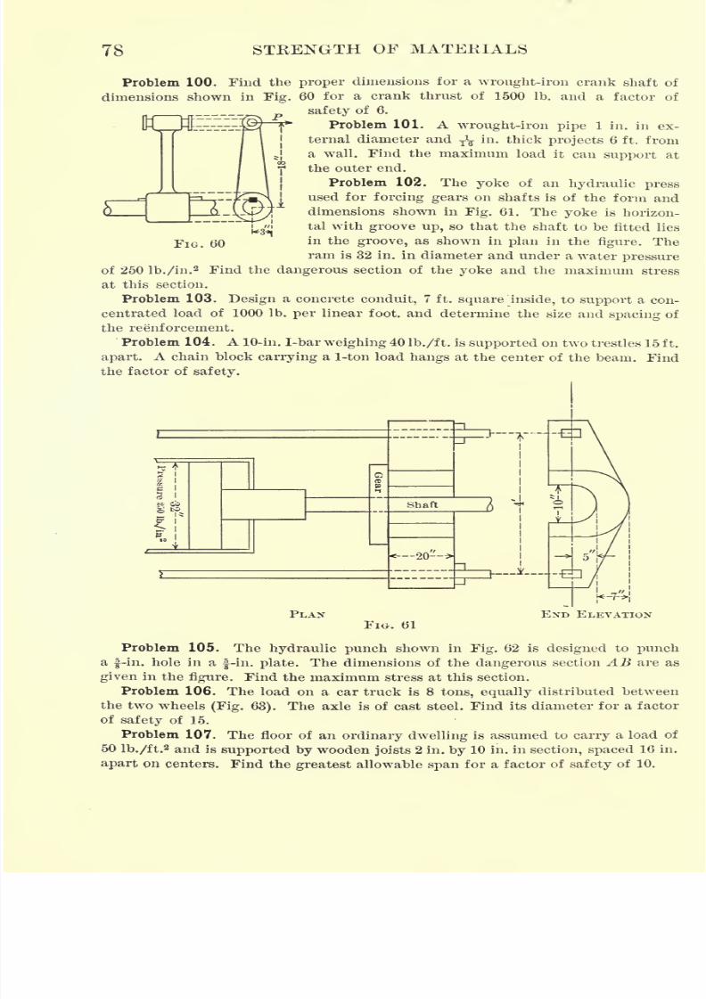
7/30/2019 Textbook on Streng 00 Slo Crich
http://slidepdf.com/reader/full/textbook-on-streng-00-slo-crich 120/433
78 STRENGTH OF MATERIALS
Problem 100. Find the proper dimensions for a wrought-iron crank shaft of
dimensions shown in Fig. 60 for a crank thrust of 1500 Ib. and a factor of
safety of 6.
Problem 101. Awrought-iron pipe
1 in. in ex-
ternal diameter and T̂ in. thick projects 6 ft. from
a wall. Find the maximum load it can support at
the outer end.
Problem 102. The yoke of an hydraulic press
used for forcing gears on shafts is of the form and
dimensions shown in Fig. 61. The yoke is horizon-
tal with groove up, so that the shaft to be fitted lies
in the groove, as shown in plan in the figure. The
ram is 32 in. in diameter and under a waterpressure
of 250 lb./in.2 Find the dangerous section of the yoke and the maximum stress
at this section.
Problem 103. Design a concrete conduit, 7 ft. square inside, to support a con-
centrated load of 1000 Ib. per linear foot, and determine the size and spacing of
the reinforcement.'
Problem 104. A 10-in. I-bar weighing 40 Ib./ft. is supported on two trestles 15 ft.
apart. A chain block carrying a 1-ton load hangs at the center of the beam. Find
the factor of safety.
FIG. 60
PLAN END ELEVATIONFIG. 61
Problem 105. The hydraulic punch shown in Fig. 62 is designed to punch
a f-in. hole in a f-in. plate. The dimensions of the dangerous section AB are as
given in the figure. Find the maximum stress at this section.
Problem 106. The load on a car truck is 8 tons, equally distributed between
the two wheels (Fig. 63). The axle is of cast steel. Find its diameter for a factor
of safety of 15.
Problem 107. The floor of an ordinary dwelling is assumed to carry a load of
50 lb./ft.2 and is supported by wooden joists 2 in. by 10 in. in section, spaced 16 in.
apart on centers. Find the greatest allowable span for a factor of safety of 10.
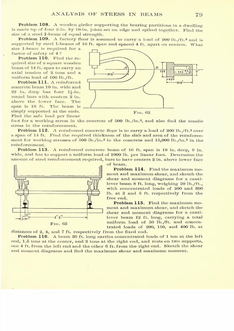
7/30/2019 Textbook on Streng 00 Slo Crich
http://slidepdf.com/reader/full/textbook-on-streng-00-slo-crich 121/433
ANALYSIS OF STRESS IN BEAMS 79
FIG. 62
Problem 108. A wooden girder supporting the bearing partitions in a dwellingis made up of four 2-in. by 10-in. joists set on edge and spiked together. Find the
size of a steel I-beam of equal strength.
Problem 109. A factory floor is assumed to carry a load of 200 lb./ft.2 and is
supported by steel I-beams of 16 ft. span and spaced 4 ft. apart on centers. Whatsize I-beam is required for a
factor of safety of 4 ?
Problem 110. Find the re-
quired size of a square wooden
beam of 14 ft. span to carry an
axial tension of 2 tons and a
uniform load of 100 lb./ft.
Problem 111. A reenforced
concrete beam 10 in. wide and22 in. deep has four 1^-in.
round bars with centers 2 in.
above the lower face. The
span is 16 ft. The beam is
simply supported at the ends.
Find the safe load per linear
foot for a working stress in the concrete of 500 lb./in.2
,and also find the tensile
stress in the reenforcement.
Problem 112. A reenforced concrete flopr is to carry a load of 200 lb./ft. 2 over
a span of 14 ft. Find the required thickness of the slab and area of the reenforce-
ment for working stresses of 500 lb./in.2 in the concrete and 15,000 lb./in.
2 in the
reenforcement.
Problem 113. A reenforced concrete beam of 16 ft. span is 18 in. deep, 9 in.
wide, and has to support a uniform load of 1000 Ib. per linear foot. Determine the
amount of steel reenforcement required, bars to have centers 2 in. above lower face
of beam.
Problem 114. Find the maximum mo-
ment and maximum shear, and sketch the
shear and moment diagrams for a canti-
lever beam 8 ft. long, weighing 20 lb./ft.,
with concentrated loads of 200 and 300
Ib. at 3 and 5 ft. respectively from the
free end.
Problem 115. Find the maximum mo-
ment and maximum shear, and sketch the
shear and moment diagrams for a canti-
lever beam 12 ft. long, carrying a total
uniform load of 50 lb./ft. and concen-
trated loads of 200, 150, and 400 Ib. at
distances of 2, 4, and 7 ft. respectively from the fixed end.
Problem 116. A beam 30 ft. long carries concentrated loads of 1 ton at the left
end, 1.5 tons at the center, and 2 tons at the right end, and rests on two supports,
one 4 ft. from the left end and the other 6 ft. from the right end. Sketch the shear
and moment diagrams and find the maximum shear and maximum moment.
FIG. 63
7/30/2019 Textbook on Streng 00 Slo Crich
http://slidepdf.com/reader/full/textbook-on-streng-00-slo-crich 122/433
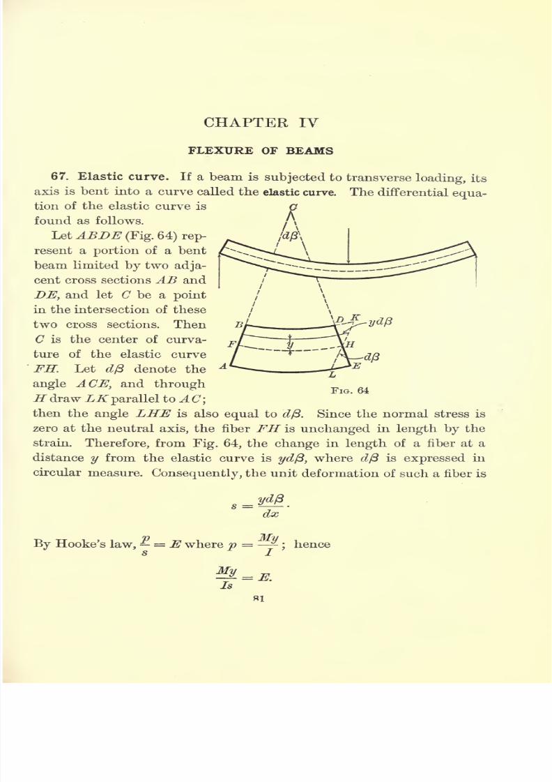
7/30/2019 Textbook on Streng 00 Slo Crich
http://slidepdf.com/reader/full/textbook-on-streng-00-slo-crich 123/433
CHAPTER IV
FLEXURE OF BEAMS
67. Elastic curve. If a beam is subjected to transverse loading, its
axis is bent into a curve called the elastic curve. The differential equa-
tion of the elastic curve is
found as follows.
LetABDE (Fig. 64) rep-
resent a portion of a bent
beam limited by two adja-
cent cross sections AB and
DE, and let C be a point
in the intersection of these
two cross sections. Then
C is the center of curva-
ture of the elastic curve
FH. Let dp denote the
angle ACEyand through
H drawLK parallel to A C\
then the angle LHE is also equal to d(3. Since the normal stress is
zero at the neutral axis, the fiber FH is unchanged in length by the
strain. Therefore, from Fig. 64, the change in length of a fiber at a
distance y from the elastic curve is yd{3, where dp is expressed in
circular measure. Consequently, the unit deformation of such a fiber is
s =dx
By Hooke's law, = E where p = -;hence
s J.
Is
81
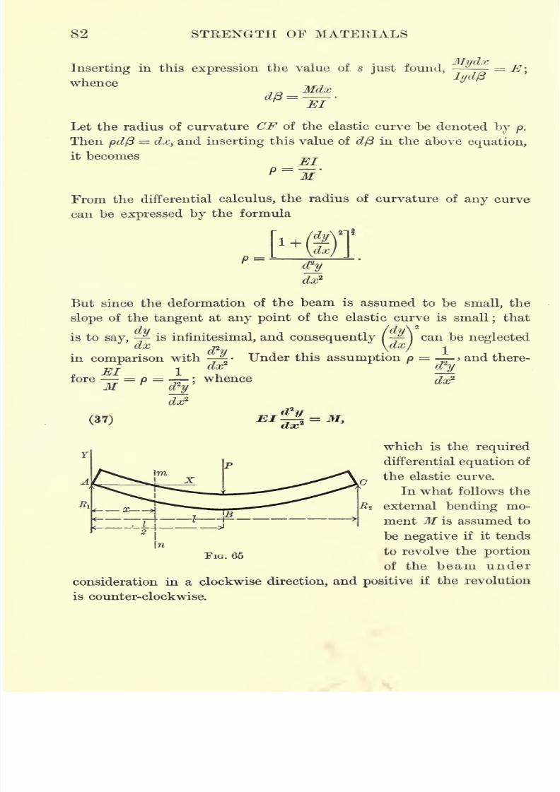
7/30/2019 Textbook on Streng 00 Slo Crich
http://slidepdf.com/reader/full/textbook-on-streng-00-slo-crich 124/433
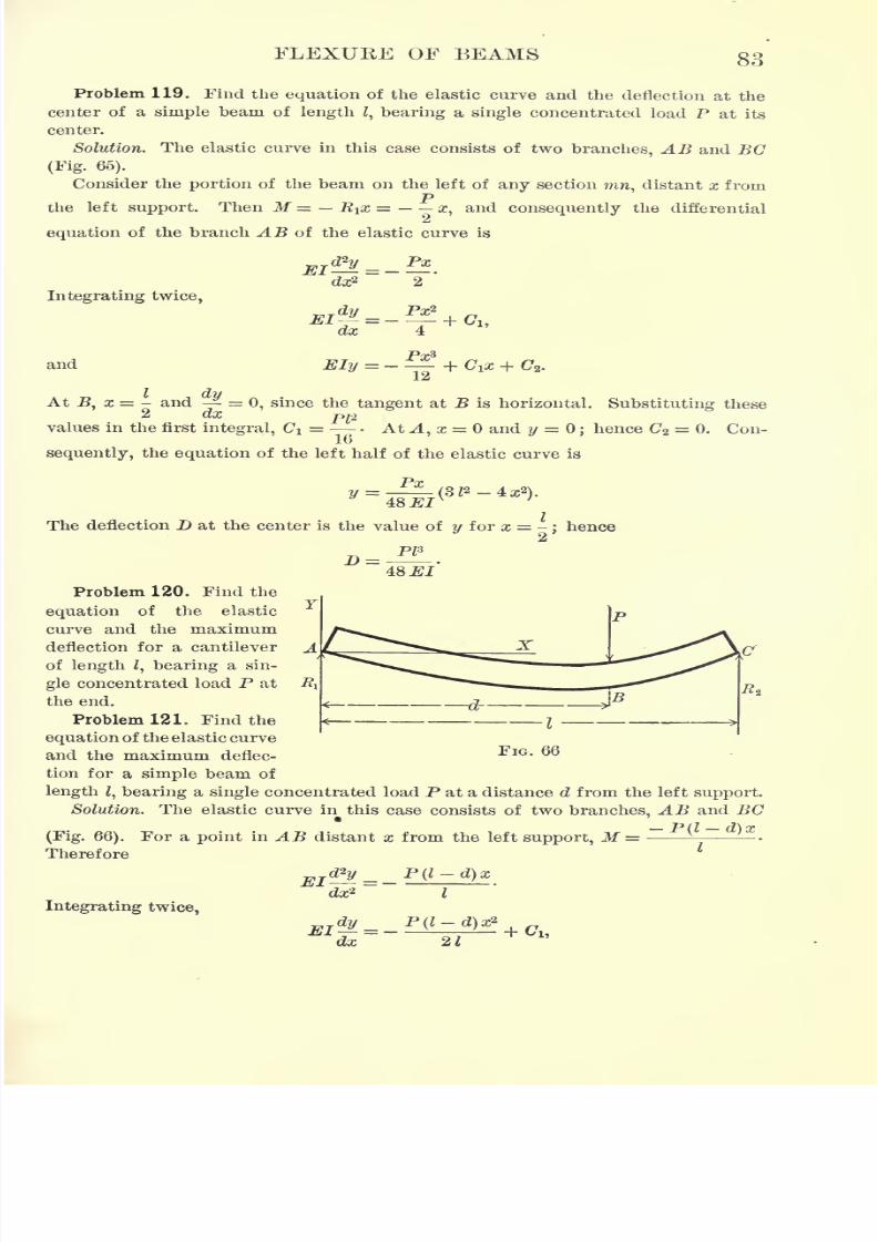
7/30/2019 Textbook on Streng 00 Slo Crich
http://slidepdf.com/reader/full/textbook-on-streng-00-slo-crich 125/433
FLEXUKE OF BEAMS 83
Problem 119. Find the equation of the elastic curve and the deflection at the
center of a simple beam of length Z, bearing a single concentrated load P at its
center.
Solution. The elastic curve in this case consists of two branches, AB and BC
(Fig. 65).
Consider the portion of the beam on the left of any section mn, distant x fromP
the left support. Then M = R^x = x, and consequently the differential
equation of the branch AB of the elastic curve is
Integrating twice,
dx2
dy
and C2 .
At.B, x = - and =
0, since the tangent at B is horizontal. Substituting thesedx
PI*values in the first integral, Ci = - At A, x = and y = ;
hence C2 = 0. Con-
sequently, the equation of the left half of the elastic curve is
Px .
y =48 El
The deflection D at the center is the value of y for x = -;hence
48 El
Problem 120. Find the
equation of the elastic
curve and the maximum
deflection for a cantilever
of length Z, bearing a sin-
gle concentrated load P at
the end.
Problem 121. Find the
equation of the elastic curve
and the maximum deflec--^IG - 6^
tion for a simple beam of
length Z, bearing a single concentrated load P at a distance d from the left support.
Solution. The elastic curve in this case consists of twobranches, AB
and BC
(Fig. 66). For a point in AB distant x from the left support, M =Therefore
P(l-d)xJTjJ. =
dx2
Integrating twice,
-P(l-d)xI

7/30/2019 Textbook on Streng 00 Slo Crich
http://slidepdf.com/reader/full/textbook-on-streng-00-slo-crich 126/433
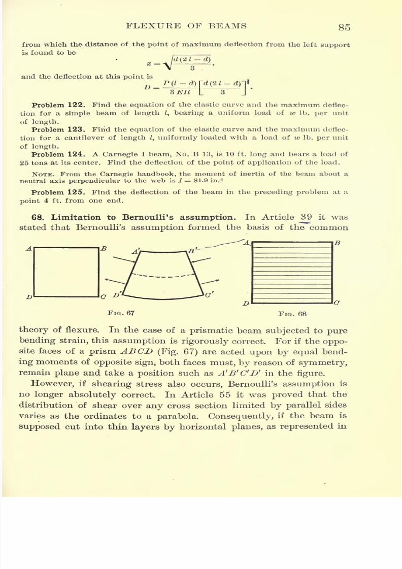
7/30/2019 Textbook on Streng 00 Slo Crich
http://slidepdf.com/reader/full/textbook-on-streng-00-slo-crich 127/433
FLEXUKE OF BEAMS 85
from which the distance of the point of maximum deflection from the left support
is found to be
and the deflection at this point is
D =ami
Problem 122. Find the equation of the elastic curve and the maximum deflec-
tion for a simple beam of length /, bearing a uniform load of w Ib. per unit
of length.
Problem 123. Find the equation of the elastic curve and the maximum deflec-
tion for a cantilever of length I, uniformly loaded with a load of w Ib. per unit
oflength.Problem 124. A Carnegie I-beam, No. B 13, is 10 ft. long and bears a load of
25 tons at its center. Find the deflection of the point of application of the load.
NOTE. From the Carnegie handbook, the moment of inertia of the beam about a
neutral axis perpendicular to the web is I = 84.9 in. 4
Problem 125. Find the deflection of the beam in the preceding problem at a
point 4 ft. from one end.
68. Limitation to Bernoulli's assumption. In Article 39 it was
stated that Bernoulli's assumption formed the basis of the common
FIG. 68
theory of flexure. In the case of a prismatic beam subjected to pure
bending strain, this assumption is rigorously correct. For if the oppo-
site faces of a prism ABCD (Fig. 67) are acted upon by equal bend-
ing moments of opposite sign, both faces must, by reason of symmetry,
remain plane and take a position such as A'B'C'D' in the figure.
However, if shearing stress also occurs, Bernoulli's assumption is
no longer absolutely correct. In Article 55 it was proved that the
distribution 'of shear over any cross section limited by parallel sides
varies as the ordinates to a parabola. Consequently, if the beam is
supposed cut into thin layers by horizontal planes, as represented in
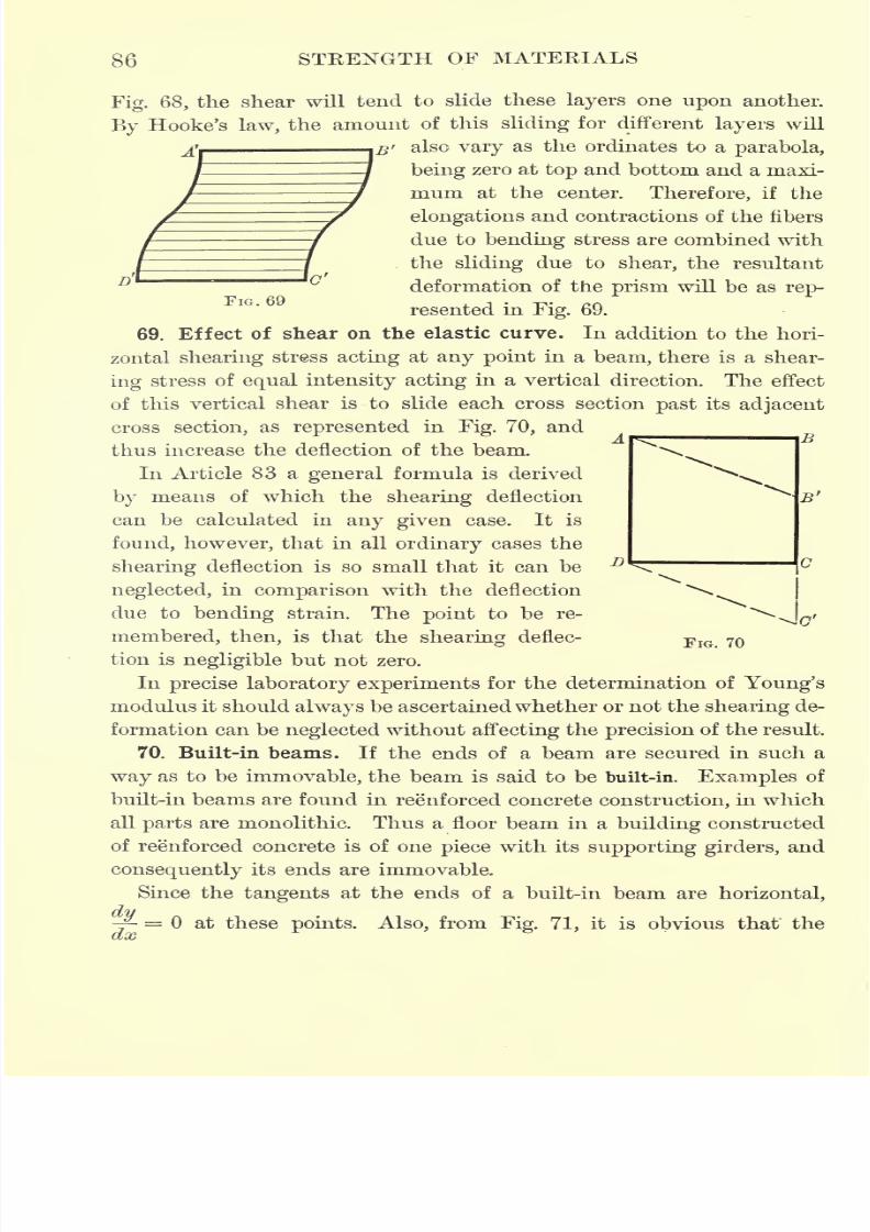
7/30/2019 Textbook on Streng 00 Slo Crich
http://slidepdf.com/reader/full/textbook-on-streng-00-slo-crich 128/433
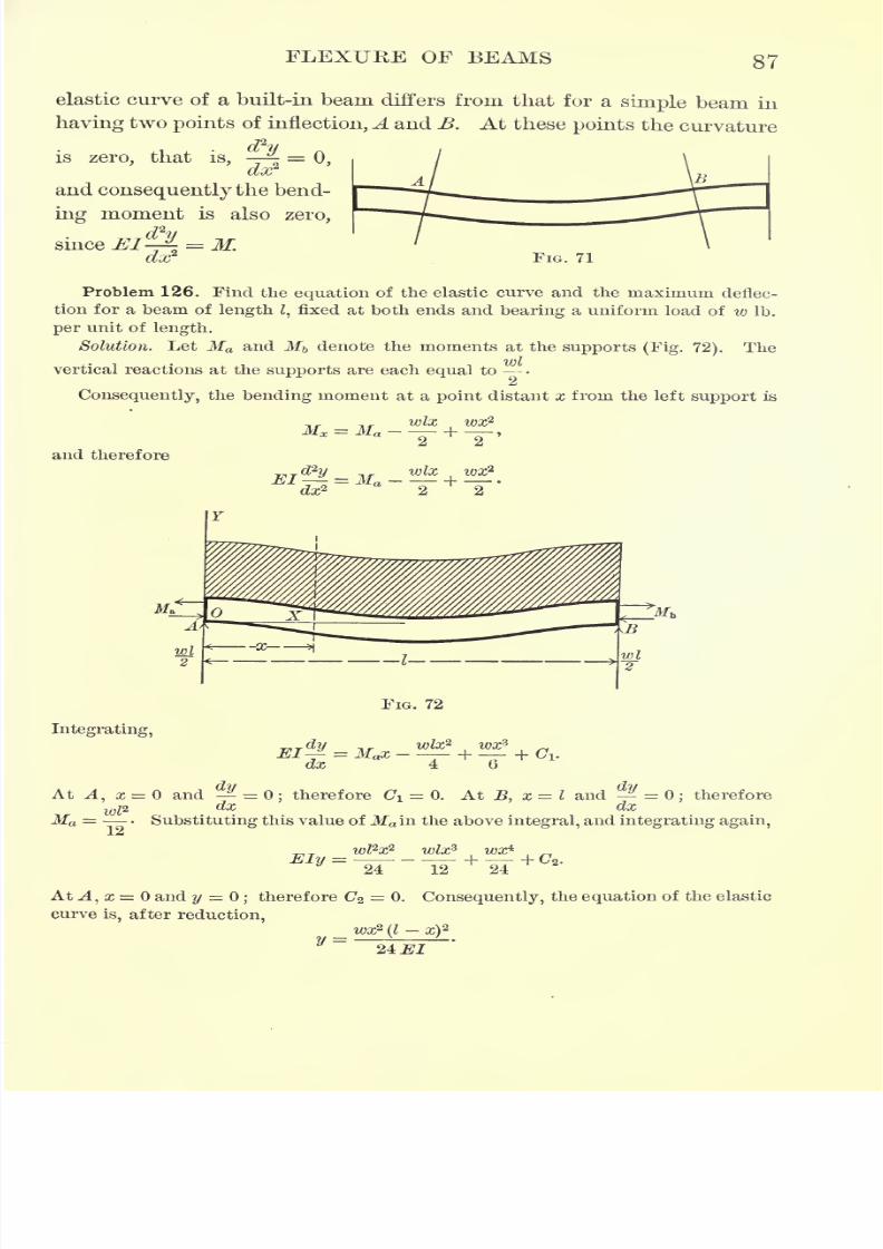
7/30/2019 Textbook on Streng 00 Slo Crich
http://slidepdf.com/reader/full/textbook-on-streng-00-slo-crich 129/433
7/30/2019 Textbook on Streng 00 Slo Crich
http://slidepdf.com/reader/full/textbook-on-streng-00-slo-crich 130/433
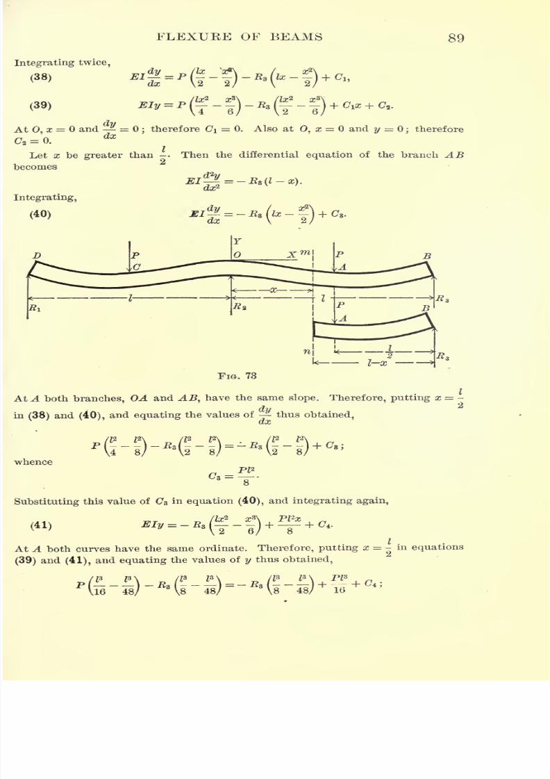
7/30/2019 Textbook on Streng 00 Slo Crich
http://slidepdf.com/reader/full/textbook-on-streng-00-slo-crich 131/433
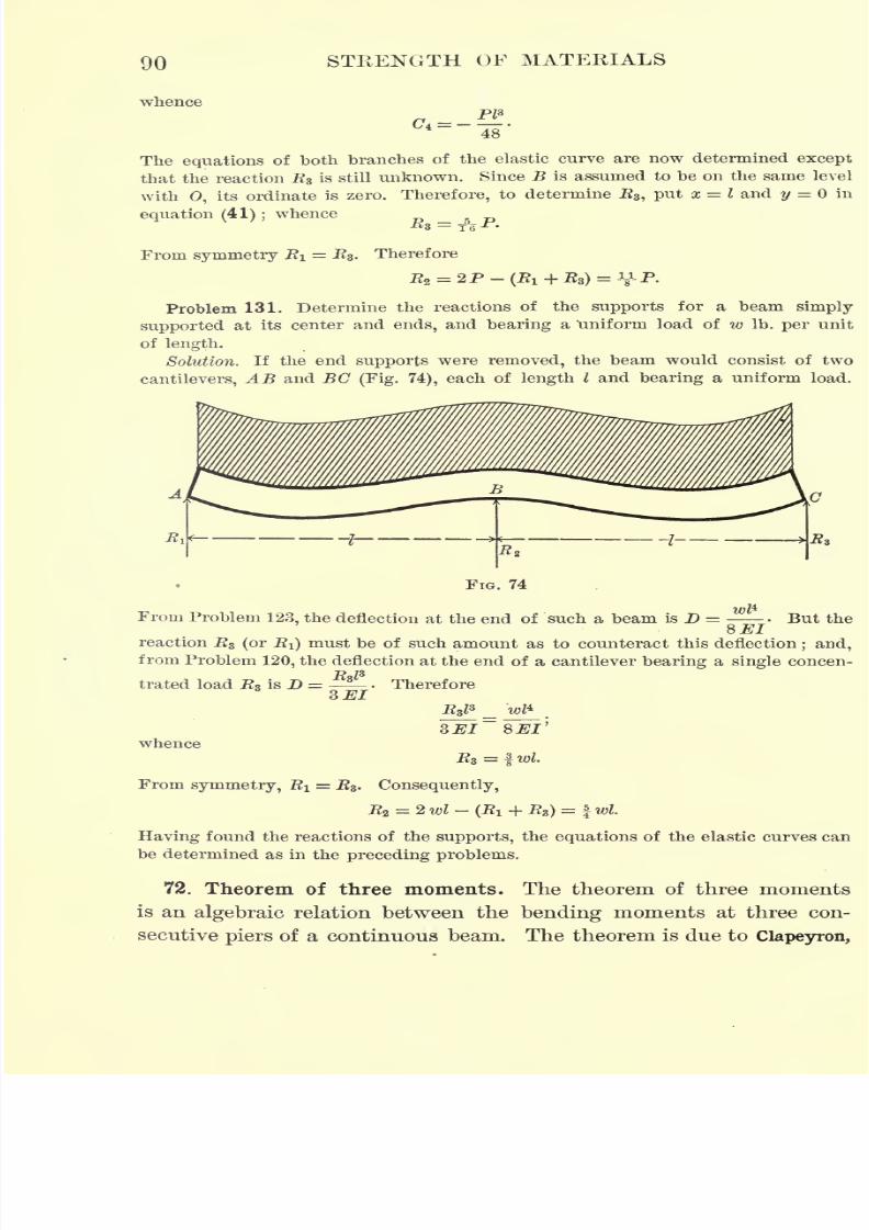
7/30/2019 Textbook on Streng 00 Slo Crich
http://slidepdf.com/reader/full/textbook-on-streng-00-slo-crich 132/433
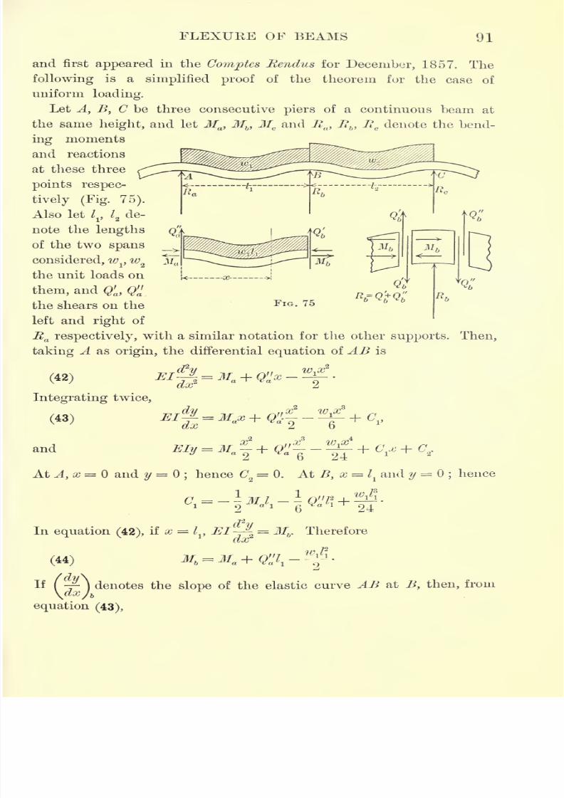
7/30/2019 Textbook on Streng 00 Slo Crich
http://slidepdf.com/reader/full/textbook-on-streng-00-slo-crich 133/433
7/30/2019 Textbook on Streng 00 Slo Crich
http://slidepdf.com/reader/full/textbook-on-streng-00-slo-crich 134/433
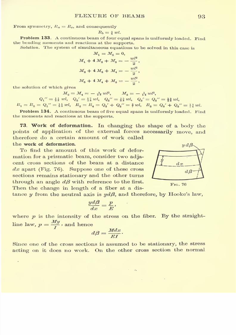
7/30/2019 Textbook on Streng 00 Slo Crich
http://slidepdf.com/reader/full/textbook-on-streng-00-slo-crich 135/433
FLEXURE OF BEAMS 93
From symmetry, Ra = JRC ,and consequently
-R& = | wl.
Problem 133. A continuous beam of four equal spans is uniformly loaded. Find
the bending moments and reactions at the supports.Solution. The system of simultaneous equations to be solved in this case is
Ml= M
5=
0,
the solution of which gives
Qi"=
i i wrf, Qa'=
\ I "I* Q2
"
JB,= fl
5= Qt
" = |i wl, E2= E
4= Q2
'
+ Q2
- =f /,
B8= Q/ + Q8
" =i| wi.
Problem 134. A continuous beam of five equal spans is uniformly loaded. Find
the moments and reactions at the supports.
73. Work of deformation. In changing the shape of a body the
points of application of the external forces necessarily move, and
therefore do a certain amount of work called
the work of deformation.
To find the amount of this work of defor-
mation for a prismatic beam, consider two adja-
cent cross sections of the beam at a distance
dx apart (Fig. 76). Suppose one of these cross
sections remains stationary and the other turns
through an angle d/3 with reference to the first.
Then the change hi length of a fiber at a dis-
tance y from the neutral axis is ydft, and therefore, by Hooke's law,
_ pdx E
where
pis the
intensityof the stress on the fiber.
Bythe
straight-
line law, p = -> and hence
Mdx
Since one of the cross sections is assumed to be stationary, the stress
acting on it does no work. On the other cross section the normal
7/30/2019 Textbook on Streng 00 Slo Crich
http://slidepdf.com/reader/full/textbook-on-streng-00-slo-crich 136/433
94 STEEXGTH OF MATERIALS
stress forms a moment equal to M. This moment is zero when first
applied, and gradually increases to its full value, its average value
being \M. Therefore the work done by the normal stress on this
cross section is 2,
Hence the total work of deformation for the entire beam is
Problem 135. As an application of the above, find the deflection at the center
of a simple beam of length /, bearing a single concentrated load P at the center.
Solution. Let D denote the deflection at the center. Then the external work
of deformation is
W= | PD.
PxAt a point distant x from the left support the bending moment is M =
,and
consequently the internal work of deformation is
96 El
1 P2/3 Pls
Therefore - PI) =;whence 1) =
2 96 El 48 El
Problem 136. Find the internal work of deformation for a rectangular wooden
beam 10 ft. long, 10 in. deep, and 8 in. wide, which bears a uniform load of 250 Ib.
per foot of length.
74. Impact and resilience. If the stress lies within the elastic
limit of the material, the body returns to its original shape upon
removal of the external forces, and the internal work of deformation
is given out again in the form of mechanical energy. The internal
work of deformation is thus a form of potential energy, and from
this point of view is called resilience. The work done in straining a
unit volume of a material to the elastic limit is called the modulus
of elastic resilience of the material.
It is therefore represented by the area under the strain curve up
to the elastic limit, or, expressed as a formula,
(stress at elastic limit)2
Mod. elas. resilience = -
2 modulus of elasticity
7/30/2019 Textbook on Streng 00 Slo Crich
http://slidepdf.com/reader/full/textbook-on-streng-00-slo-crich 137/433
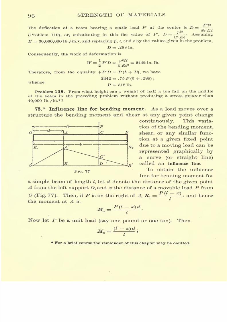
7/30/2019 Textbook on Streng 00 Slo Crich
http://slidepdf.com/reader/full/textbook-on-streng-00-slo-crich 138/433
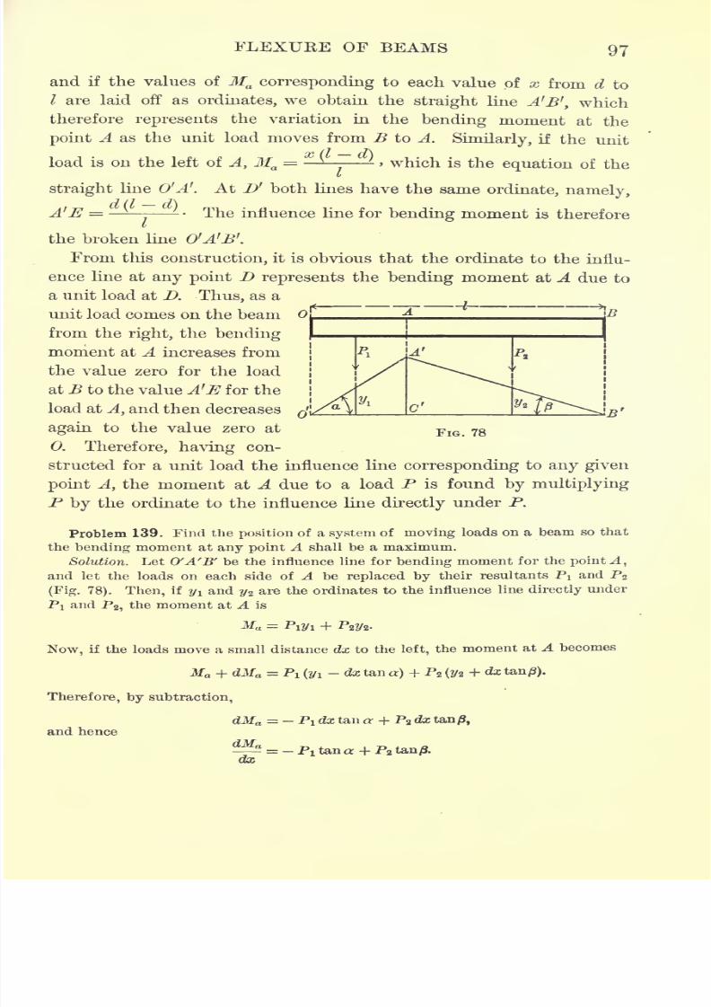
7/30/2019 Textbook on Streng 00 Slo Crich
http://slidepdf.com/reader/full/textbook-on-streng-00-slo-crich 139/433
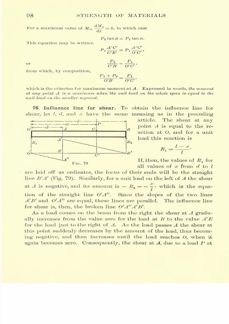
7/30/2019 Textbook on Streng 00 Slo Crich
http://slidepdf.com/reader/full/textbook-on-streng-00-slo-crich 140/433
98 STRENGTH OF MATERIALS
For a maximum value of Ma ,
^-? =0, in which case
dx
This equation may be written
P2 tan/3 =
pA'C'
=C'B'
P2
A'C'
O'C''
from which, by composition,
C'B' O'C"
Pi
0'C"'
which is the criterion for maximum moment at A. Expressed in words, the moment
at any point A is a maximum when the unit load on the whole span is equal to the
unit load on the smaller segment.
76. Influence line for shear. To obtain the influence line for
shear, let/, d, and x have the same meaning as in the preceding
article. The shear at any
point A is equal to the re-
action at 0, and for a unit
load this reaction is
I x
o
FIG. 79
I
If, then, the values of 7^ for
all values of x from d to I
are laid off as ordinates, the locus of their ends will be the straight
line B'A'(Fig. 79). Similarly, for a unit load on the left of A the shear
/yt
at A is negative, and its amount is R2= > which is the equa-
tion of the straight line O'A". Since the slopes of the two lines
A'B' and O'A" are equal, these lines are parallel. The influence line
for shear is, then, the broken line 0'A"A'I>'.
As a load comes on the beam from the right the shear at A gradu-
ally increases from the value zero for the load at B to the value A'E
for the load just to the right of A. As the load passes A the shear at
this point suddenly decreases by the amount of the load, thus becom-
ing negative, and then increases until the load reaches 0, when it
again becomes zero. Consequently, the shear at A, due to a load P at
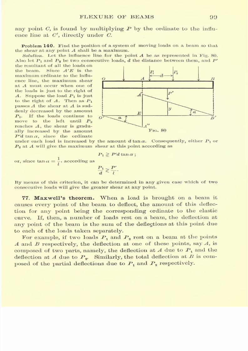
7/30/2019 Textbook on Streng 00 Slo Crich
http://slidepdf.com/reader/full/textbook-on-streng-00-slo-crich 141/433
FLEXURE OF BEAMS 99
any point C, is found by multiplying P by the ordinate to the influ-
ence line at C', directly under C.
Problem 140. Find the position of a system of moving loads on a beam so that
the shear at any point A shall be a maximum.
Solution. Let the influence line for the point A be as represented in Fig. 80.
Also let PI and P2 be two consecutive loads, d the distance between them, and P'
the resultant of all the loads on
the beam. Since A'E is the
maximum ordinate to the influ-
ence line, the maximum shear
at A must occur when one of
the loads is just to the right of
A. Suppose the load PI is just
to the right of A. Then as PI
passes A the shear at A is sud-
denly decreased by the amount
PI. If the loads continue to
move to the left until P2
reaches A, the shear is gradu-
ally increased by the amount
P'd tan a, since the ordinateunder each load is increased by the amount d tan a. Consequently, either Pt or
PZ at A will give the maximum shear at this point according as
A
E13'
FIG. 80
PI ^ P'd tan a;
or, since tana = -, according as
By means of this criterion, it can be determined in any given case which of twoconsecutive loads will give the greater shear at any point.
77. Maxwell's theorem. When a load is brought on a beam it
causes every point of the beam to deflect, the amount of this deflec-
tion for any point being the corresponding ordinate to the elastic
curve. If, then, a number of loads rest on a beam, the deflection at
any point of the beam is the sum of the deflections at this point due
to each of the loads taken separately.
For example, if two loads Pland P
2rest on a beam at the points
A and B respectively, the deflection at one of these points, say A, is
composed of two parts, namely, the deflection at A due to Pland the
deflection at A due to P2
. Similarly, the total deflection at B is com-
posed of the partial deflections due to Pland P
z respectively.
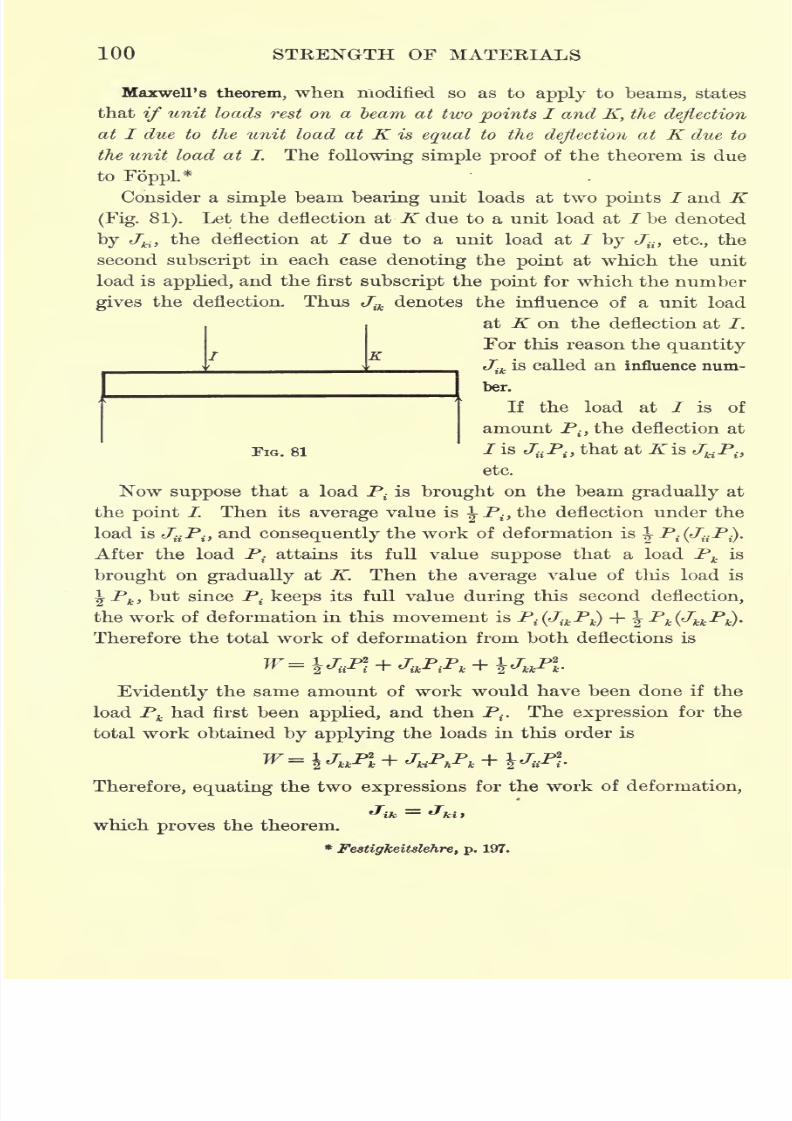
7/30/2019 Textbook on Streng 00 Slo Crich
http://slidepdf.com/reader/full/textbook-on-streng-00-slo-crich 142/433
100 STRENGTH OF MATERIALS
Maxwell's theorem, when modified so as to apply to beams, states
that if unit loads rest on a beam at two points I and K, the deflection
at I due to the unit load at K is equal to the deflection at K due to
the unit load at L The following simple proof of the theorem is due
to FoppL*
Consider a simple beam bearing unit loads at two points / and K(Fig. 81). Let the deflection at JTdue to a unit load at /be denoted
by c7"H ,the deflection at / due to a unit load at / by J{i) etc., the
second subscript in each case denoting the point at which the unit
load is applied, and the first subscript the point for which the number
gives the deflection. Thus Jik
denotes the influence of a unit load
at K on the deflection at /.
For this reason the quantity
Jik
is called an influence num-
ber.
If the load at I is of
amount Pitthe deflection at
FIG. 81 / is JaPitthat at K is JKPit
etc.
Now suppose that a load P{is brought on the beam gradually at
the point /. Then its average value is ^-Pt.,the deflection under the
load is JaPitand consequently the work of deformation is \ P.(Jf.P^.
After the load P. attains its full value suppose that a load Pk is
brought
ongradually
at K. Then the
average
value of this load is
\Pk ,but since P
{ keeps its full value during this second deflection,
the work of deformation in this movement is P^J^P^ + J- -^VM^-P*)'
Therefore the total work of deformation from both deflections is
Evidently the same amount of work would have been done if the
load Pkhad first been applied, and then P
t. The expression for the
total work obtained by applying the loads in this order is
Therefore, equating the two expressions for the work of deformation,
which proves the theorem.
*Festigkeitslehre, p. 197.
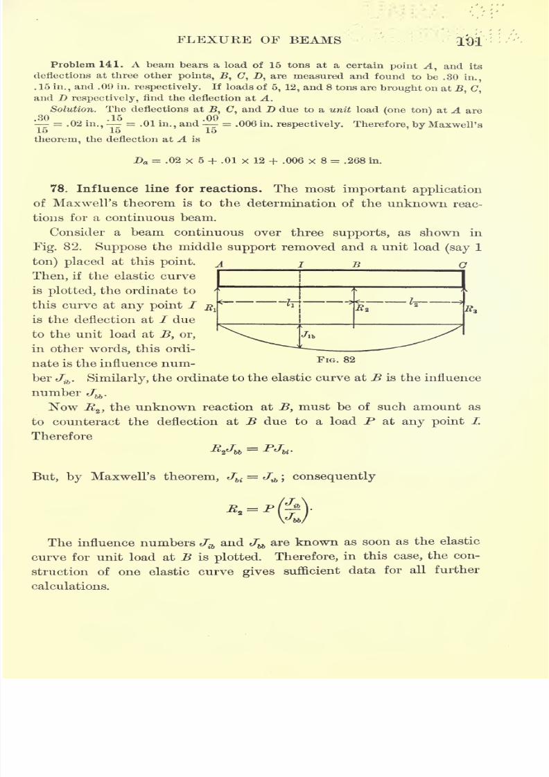
7/30/2019 Textbook on Streng 00 Slo Crich
http://slidepdf.com/reader/full/textbook-on-streng-00-slo-crich 143/433
FLEXURE OF BEAMS
Problem 141. A beam bears a load of 15 tons at a certain point A, and its
deflections at three other points, B, (7, D, are measured and found to be .30in.,
. 16 in.,and .09 in. respectively. If loads of 6, 12, and 8 tons are brought on at
.B, C,
and D respectively, find the deflection at A.Solution. The deflections at U, C, and D due to a unit load (one ton) at A are
'- = .02 in.,'-
-.01 in., and
'
= .006 in. respectively. Therefore, by Maxwell's15 16 16
theorem, the deflection at A is
Da = .02 x 6 + .01 x 12 + .006 x 8 = .268 in.
78. Influence line for reactions. The most important application
of Maxwell's theorem is to the determination of the unknown reac-
tions for a continuous beam.
Consider a beam continuous over three supports, as shown in
Fig. 82. Suppose the middle support removed and a unit load (say 1
ton) placed at this point. A I B a
Then, if the elastic curve
is plotted, the ordinate to
this curve at any point /
is the deflection at I due
to the unit load at B, or,
in other words, this ordi-
nate is the influence num-
ber Jib
. Similarly, the ordinate to the elastic curve at B is the influence
number Jbb
.
Now -K2 , the unknown reaction at B, must be of such amount as
to counteract the deflection at B due to a load P at any point /.
Therefore
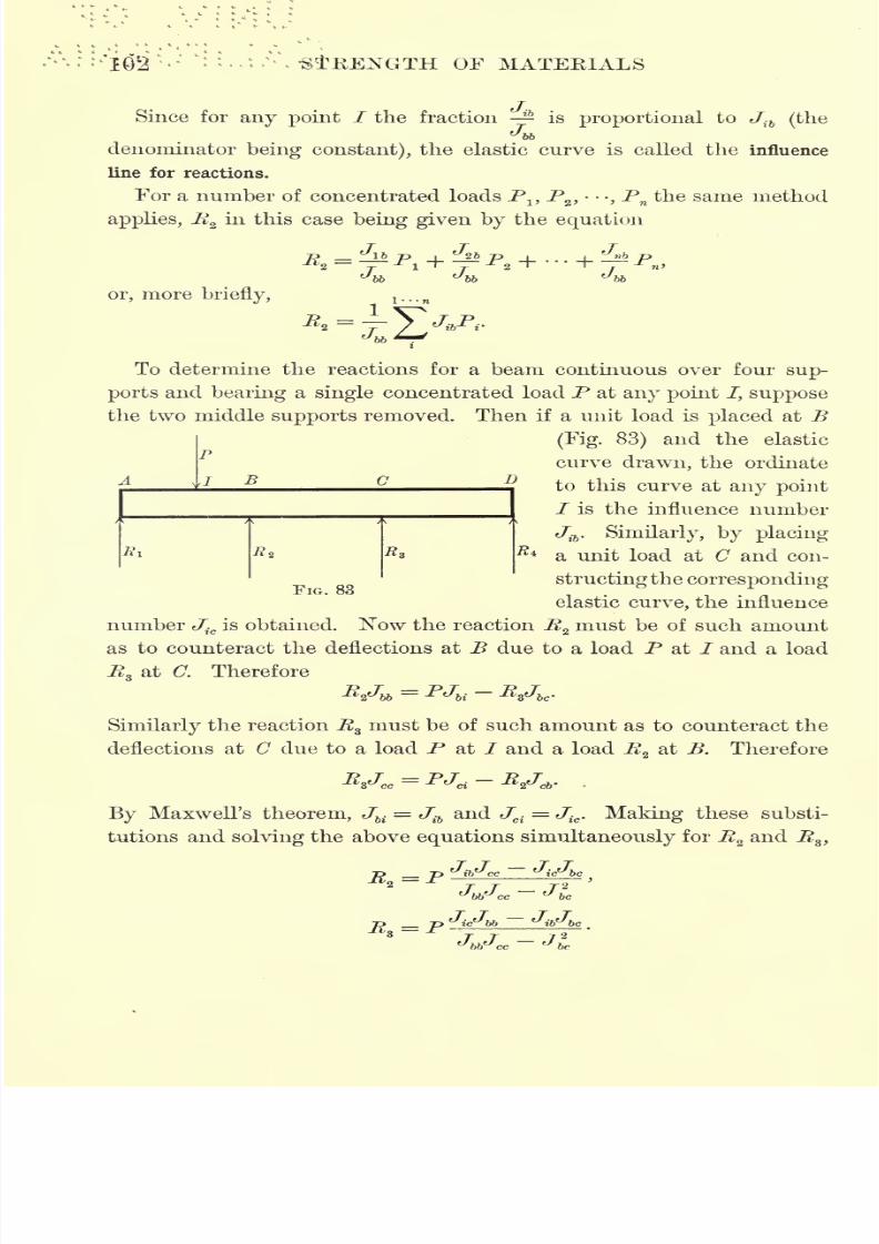
7/30/2019 Textbook on Streng 00 Slo Crich
http://slidepdf.com/reader/full/textbook-on-streng-00-slo-crich 144/433
i\fitBBNGTH OF MATERIALS
Since for any point / the fraction is proportional to Jib (the
Jbb
denominator being constant), the elastic curve is called the influence
line for reactions.
For a number of concentrated loads P1?P
2 , -,P
nthe same method
applies, Rzin this case being given by the equation
J U J
or, more briefly,
To determine the reactions for a beam continuous over four sup-
ports and bearing a single concentrated load P at any point /, suppose
the two middle supports removed. Then if a unit load is placed at B
(Fig. 83) and the elastic
curve drawn, the ordinate
to this curve at any point
/ is the influence number
Jib
. Similarly, by placing
a unit load at C and con-
structing the correspondingFIG. 83
elastic curve, the influence
number Jic
is obtained. Now the reaction Rzmust be of such amount
as to counteract the deflections at B due to a load P at / and a load
R at a Therefore
A}
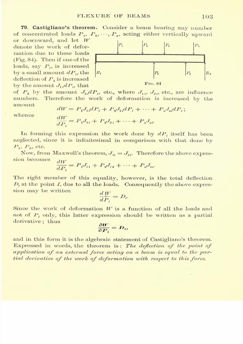
7/30/2019 Textbook on Streng 00 Slo Crich
http://slidepdf.com/reader/full/textbook-on-streng-00-slo-crich 145/433
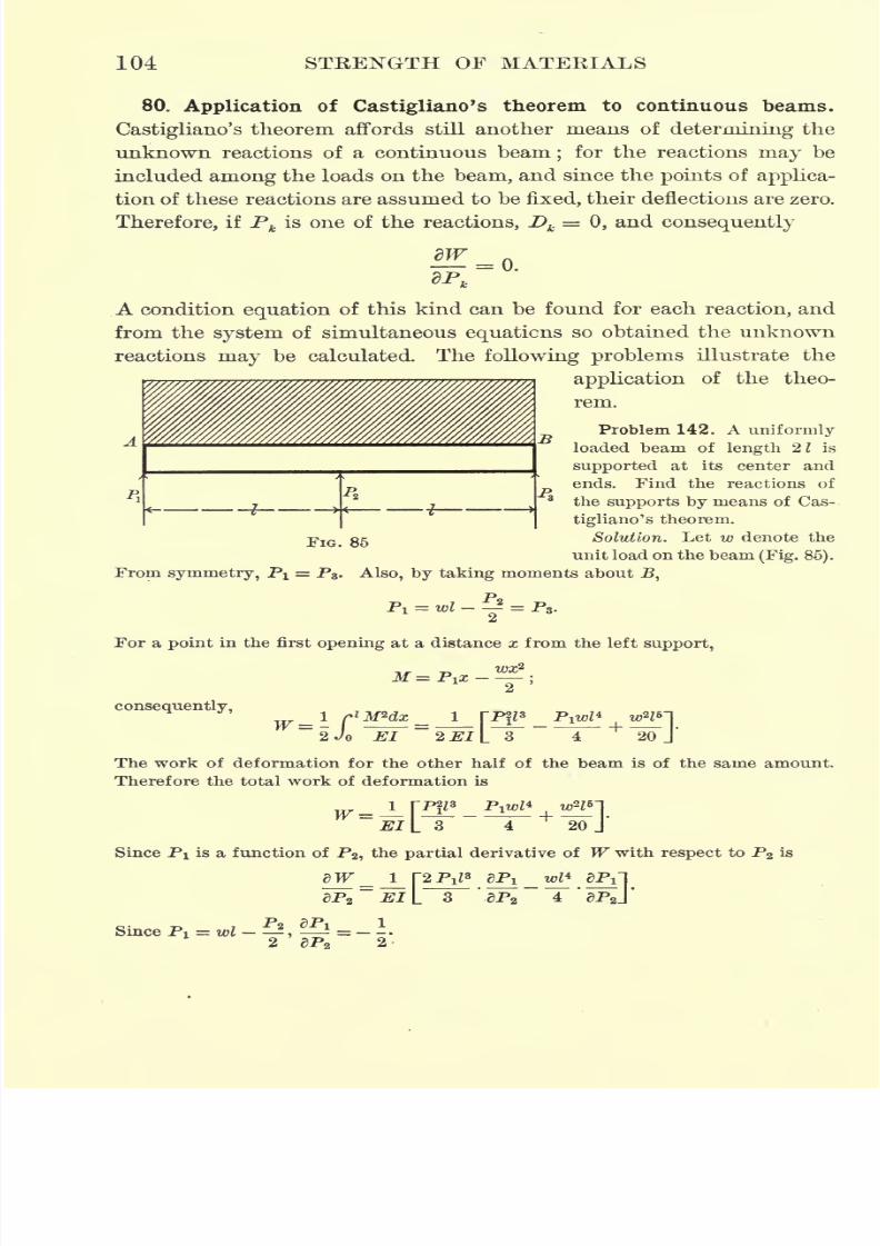
7/30/2019 Textbook on Streng 00 Slo Crich
http://slidepdf.com/reader/full/textbook-on-streng-00-slo-crich 146/433
104 STRENGTH OF MATERIALS
80. Application of Castigliano's theorem to continuous beams.
Castigliano's theorem affords still another means of determining the
unknown reactions of a continuous beam;for the reactions
maybe
included among the loads on the beam, and since the points of applica-
tion of these reactions are assumed to be fixed, their deflections are zero.
Therefore, if Pk
is one of the reactions, Dk= 0, and consequently
o.
A condition equation of this kind can be found for each reaction, and
from the system of simultaneous equations so obtained the unknown
reactions may be calculated. The following problems illustrate the
application of the theo-
rem.
Problem 142. A uniformly
loaded beam of length 2 1 is
supported at its center and
ends. Find the reactions ofthe supports by means of Cas-
tigliano's theorem.
Solution. Let w denote the
unit load on the beam (Fig. 85).
-P.
FIG. 85
From symmetry, PI = P8 . Also, by taking moments aboutJB,
For apoint
in the first
openingat a distance x from the left
support,
~~1
2'
consequently,
W=\LJo El 2 El I
uw~\
20 J'
The work of deformation for the other half of the beam is of the same amount.
Therefore the total work of deformation is
W ~El[ 8 4+
20 J'
Since PI is a function of P2 ,the partial derivative of W with respect to P2 is
dTT_j_pPiJ8
5Pi_w^4
aPil
ap .BiL s '.&PS 4'*aPsj
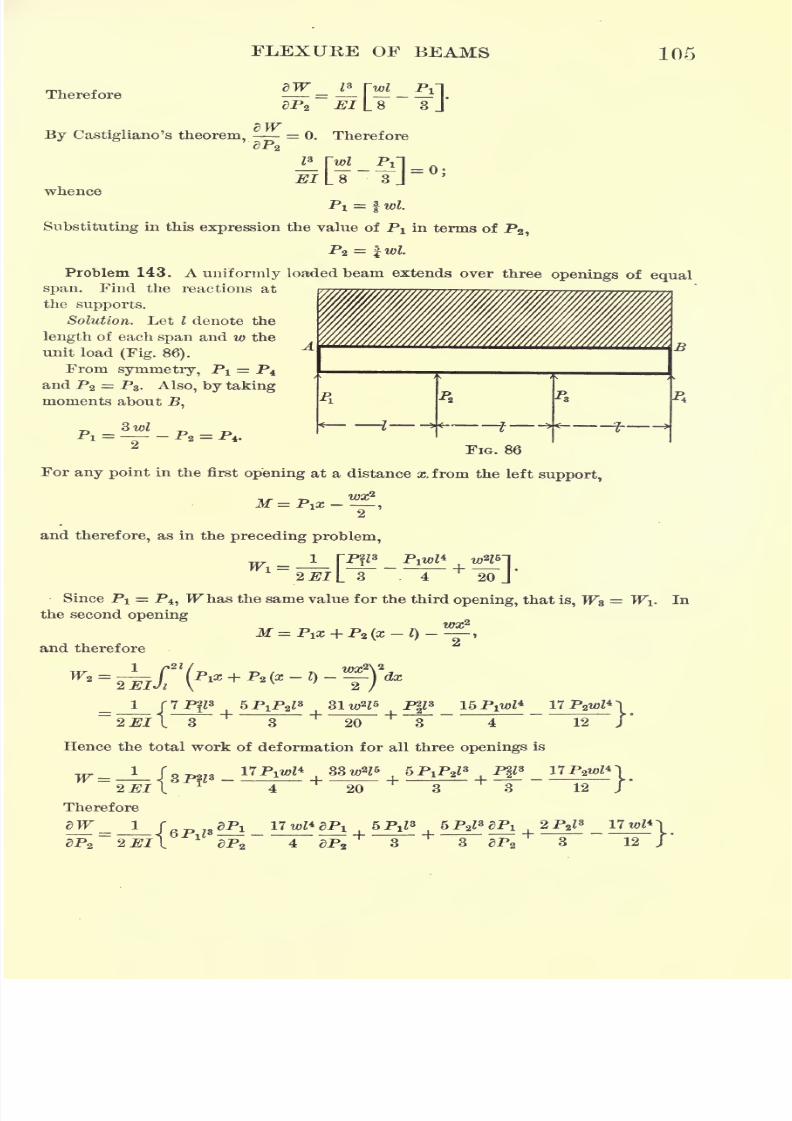
7/30/2019 Textbook on Streng 00 Slo Crich
http://slidepdf.com/reader/full/textbook-on-streng-00-slo-crich 147/433
7/30/2019 Textbook on Streng 00 Slo Crich
http://slidepdf.com/reader/full/textbook-on-streng-00-slo-crich 148/433
106 STRENGTH OF MATERIALS
Since PI = - P2 ,=
1, and hence2 dPz
e)P2
Putting =0, and substituting for Pj its value in terms of P2 ,
whence P2=
and consequently PI = fwZ.
81. Principle of least work. Differentiating partially with respect
dWto P
tboth members of the equation
= Di9we have
dP
As the load increases the deflection increases, and vice versa. There-o
y~\
i
fore, since dZ>tand dP. have the same sign,
i
is positive and hence
.
-is also positive. But, from the differential calculus,
dW A ?W^ n= and _>0
are the conditions that W shall be a minimum. Consequently, the
reactions of a continuous beam, calculated from the condition = 0,
ftP<
are such that they make the work of deformation a minimum.
In Article 73 it was pointed out that the internal work of defor-
mation is a form of potential energy. The above is thus a special
case of what is known as the principle of least work, the general state-
ment of this principle being expressed by the following theorem :
For stable equilibrium the potential energy of any system is a
minimum.
The importance of the principle of least work is due to the fact
that it is a general mechanical principle, affording a general solution
of all problems involving the static equilibrium of elastic solids. Its
most useful application, perhaps, is to problems which are other-
wise statically indeterminate, that is to say, problems in which the
7/30/2019 Textbook on Streng 00 Slo Crich
http://slidepdf.com/reader/full/textbook-on-streng-00-slo-crich 149/433
FLEXURE OF BEAMS 107
number of unknown quantities involved is greater than the number
of relations furnished by the ordinary conditions of equilibrium.
Thegeneral
solution of
any problem
of this nature
bythe method
of least work is as follows : First express the work of deformation
(or potential energy) in terms of the unknown quantities which it is
required to determine. Then the condition that this expression shall
be a minimum resolves itself into the condition that the partial
derivatives of the potential energy with respect to each of the un-
knowns involved shall be zero. In this way we obtain exactly as
many equations
as unknowns, from which these unknownquantities
may be found.
Thus if W denotes the work of deformation and Pv Pz , -,P
nthe
unknown quantities to be found, first express W7"
as a function of
these unknowns, say W(PltP
2 ,---,PW). Then the condition for a
minimum is dW= 0, or, expressing the total differential dW in terms
of its partial derivatives with respect to the various unknowns,
.,..Since P
JtP
2 ,
-
,P
Bare assumed to be independent, in order for this
relation to be satisfied identically, that is for all values of PltP
z ,>,
Pw,
the coefficients of dPv dP2 ,
- -,dPn must all be zero;that is,
_
We have, therefore, n equations from which to determine the n
unknowns PlfP
2,--,Pn.
Before applying this principle it is necessary to find an expression
for the work of deformation of elastic solids subjected to direct stress
or to bending stress.
1. Direct stress. Consider a prismatic bar of length / and cross
section F, which is subjected to a direct stress, either tension or
compression, of intensity p. Then from Hooke's law
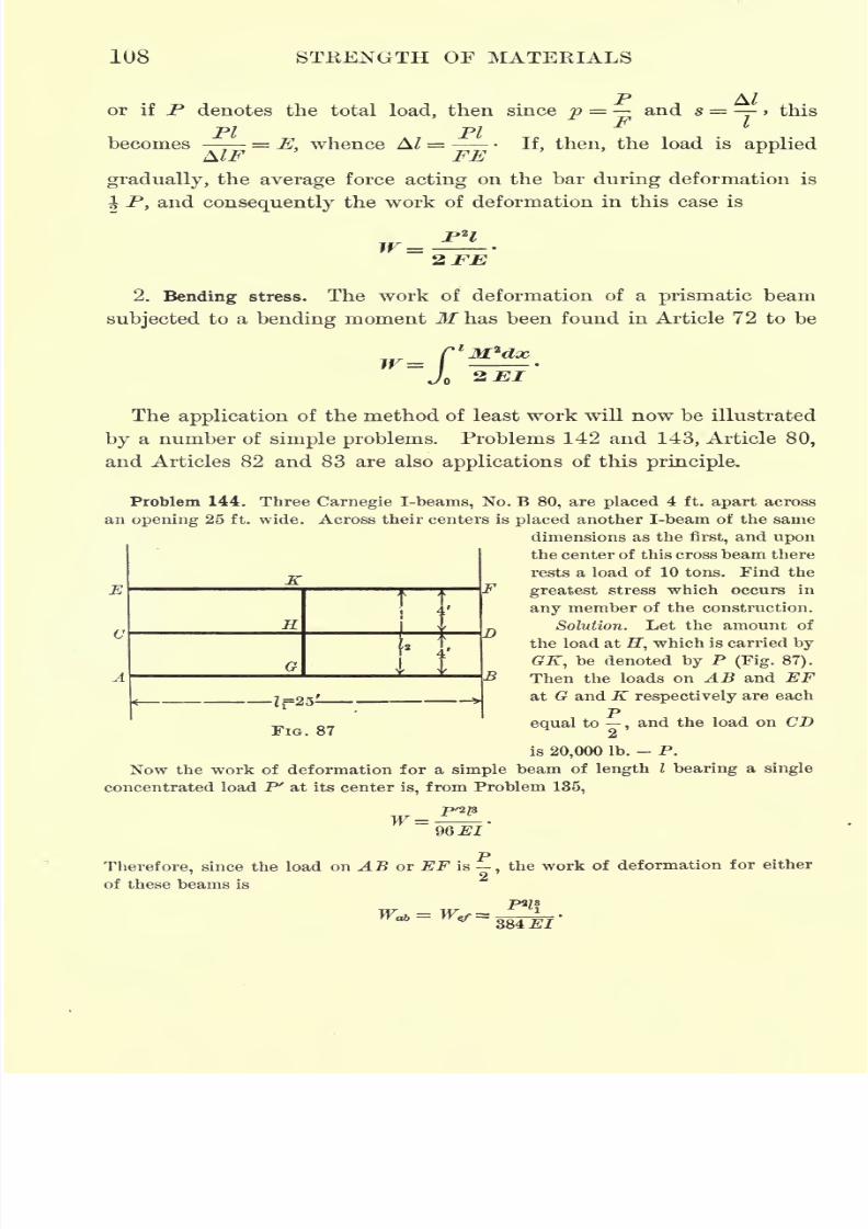
7/30/2019 Textbook on Streng 00 Slo Crich
http://slidepdf.com/reader/full/textbook-on-streng-00-slo-crich 150/433
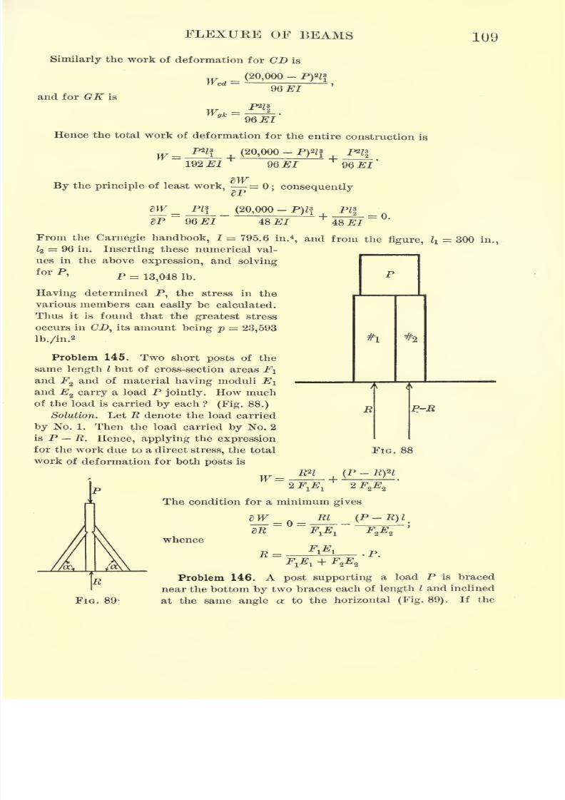
7/30/2019 Textbook on Streng 00 Slo Crich
http://slidepdf.com/reader/full/textbook-on-streng-00-slo-crich 151/433
FLEXUKE OF BEAMS 109
Similarly the work of deformation for CD is
(20,000-
and for GK is
96 El
96 #1
Hence the total work of deformation for the entire construction is
... P*l*, (20,000-
192 #/ 96.EI
By the principle of least work, = 0; consequentlydP
dW _ PI* (20,000 - P)l* PI*
dP 96 El 48 El 48 #/=o.
From the Carnegie handbook, I = 795.6 in.*, and from the figure, li= 300 in.,
Z2 = 96 in. Inserting these numerical val-
ues in the above expression, and solving
for P, p _
Having determined P, the stress in the
various members can easily be calculated.
Thus it is found that the greatest stress
occurs in CD, its amount being p = 23,593
Ib./in.a
Problem 145. Two short posts of the
same length I but of cross-section areas FI
and F2and of material having moduli EI
and E2 carry a load P jointly. How much
of the load is carried by each ? (Fig. 88.)
Solution. Let R denote the load carried
by No. 1. Then the load carried by No. 2
is P R. Hence, applying the expression,
for the work due to a direct stress, the total
work of deformation for both posts is
W =
P-R
FIG. 88
The condition for a minimum gives
whence
R= r.
FIG. 89-
Problem 146. A post supporting a load P is braced
near the bottom by two braces each of length I and inclined
at the same angle a to the horizontal (Fig. 89). If the

7/30/2019 Textbook on Streng 00 Slo Crich
http://slidepdf.com/reader/full/textbook-on-streng-00-slo-crich 152/433
110 STRENGTH OF MATERIALS
upright is of cross section FI and has a modulus J?1 ,and the braces are each of
cross section F2and modulus E2 ,
show that the load R carried by the upright is
given by
Problem 147. A platform 12ft. x 18ft. in size and weighing 1 ton is supported
at the corners by four wooden legs, each 8 in. square. A load of 5 tons is placed
on this platform 4 ft. from each of two adjacent edges. How much of the load is
carried by each leg ?
Problem 148. A beam 20 ft. long is supported at each end and at a point dis-
tant 5 ft. from the left end. It carries a load of 180 Ib. at the left end, and of
125 Ib. at a point distant 6 ft. from the right end. Find the reactions of the
supports.
Problem 149. Two beams are
supported
as shown
in Fig. 90, the lower beam resting on fixed end sup-
ports, and the upper beam resting on three supports,
at its center and ends. The upper beam carries a
FIG. 90 uniform load. Find the center load transmitted to
the lower beam.
Problem 150. A flitched (or composite) beam consists of a 3-in. I-beam weighing
1\ Ib./ft. and a 4-in. x 6-in. timber, the I-beam being placed underneath the wooden
beam, and the two are hung from a crane by a wrought-iron strap around the
middle. A cable is then looped over the ends of this flitched beam 2f ft. distant
from the center on each side, and a load of 1000 Ib. supported by the loop. Find
the total load carried by each beam. i
Problem 151. The king post truss shown in\*
---c 4
Fig. 91 is formed of a single beam AC resting
on supports at A and C and trussed at the center
with a strut BD, supported by two tie rods ADand DC. Determine the load R carried by the strut
BD when a load P is placed at a distance c from A.
Solution. Let R denote the stress in BD. Then if h denotes the length of the
strut BD and d the length of each tie, AD and DC, the stress in AD or DC is
in each, and the direct stress in ABC is -- Let Fv F2 ,F
3 ,denote the cross-
2 h 4/i
section areas of AC, AD, and BD respectively. Then the total work of deforma-
tion, due to direct stresses in the various members, is
R2h
In addition to this it is also necessary to consider the work of deformation due to
the bending stress in AC. At a point distant x from A this is as follows :
For x between A and P, MAP = [P(/
~c) - -1 x,
for x between P and B, NPR = PC - (- + \x,
for x between B and C, MBc = ( \(l x).
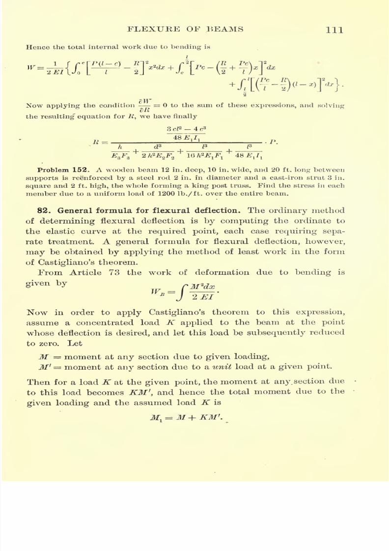
7/30/2019 Textbook on Streng 00 Slo Crich
http://slidepdf.com/reader/full/textbook-on-streng-00-slo-crich 153/433
FLEXURE OF BEAMS HI
Hence the total internal work due to bending is
Now applying the condition = to the sum of these expressions, and solving
the resulting equation for #, we have finally
3d2 -4c3
h d3
Problem 152. A wooden beam 12 in. deep, 10 in. wide, and 20 ft. long between
supports is reenforced by a steel rod 2 in. in diameter and a cast-iron strut 3 in.
square and 2 ft. high, the whole forming a king post truss. Find the stress in each
member due to a uniform load of 1200 Ib./ft. over the entire beam.
82. General formula for flexural deflection. The ordinary method
of determining flexural deflection is by computing the ordinate to
the elastic curve at the required point, each case requiring sepa-
rate treatment. A general formula for flexural deflection, however,
may be obtained by applying the method of least work in the form
of Castigliano's theorem.
From Article 73 the work of deformation due to bending is
Now in order to apply Castigliano's theorem to this expression,
assume a concentrated load K applied to the beam at the point
whose deflection is desired, and let this load be subsequently reduced
to zero. Let
M = moment at any section due to given loading,
M' = moment at any section due to a unit load at a given point.
Then for a load K at the given point, the moment at any.section due
to this load becomes KM ',and hence the total moment due to the
given loading and the assumed load K is
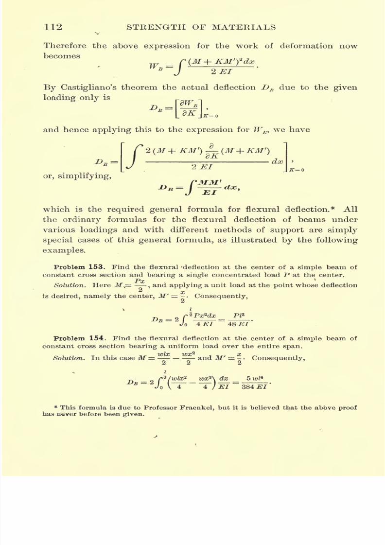
7/30/2019 Textbook on Streng 00 Slo Crich
http://slidepdf.com/reader/full/textbook-on-streng-00-slo-crich 154/433
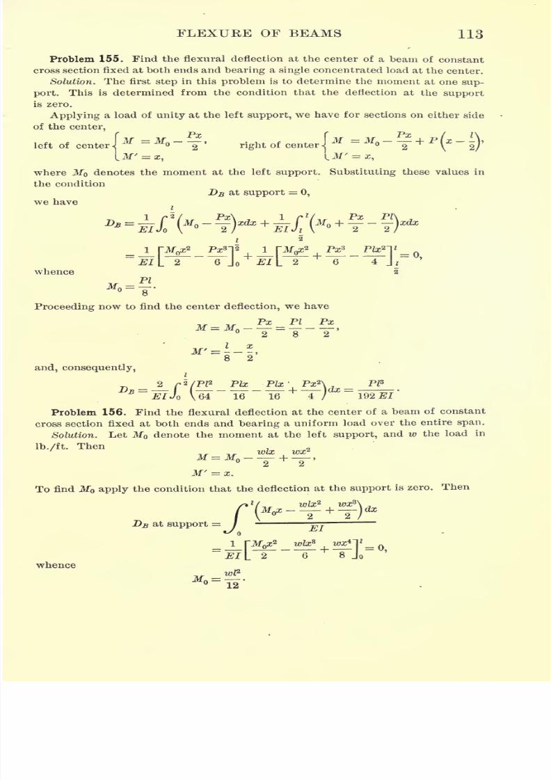
7/30/2019 Textbook on Streng 00 Slo Crich
http://slidepdf.com/reader/full/textbook-on-streng-00-slo-crich 155/433
FLEXURE OF BEAMS 113
Problem 155. Find the flexural deflection at the center of a beam of constant
cross section fixed at both ends and bearing a single concentrated load at the center.
Solution. The first step in this problem is to determine the moment at one sup-
port. This is determined from the condition that the deflection at the support
is zero.
Applying a load of unity at the left support, we have for sections on either side
of the center,
left of centerIM = N ~
Y '
right of center IM = M ~
T + P(*
~~
2~)'
\^M' = x, LM' = x,
where M denotes the moment at the left support. Substituting these values in
the condition
DB at support = 0,
we have
whence
*.=?
i pf^ Pan 2 i rn^ Px* P&2TEI\. 2
"
6 Jo JJL 2
"
6
"
4 Ji
Proceeding now to find the center deflection, we have
and, consequently,
2 r*/PP Pte -Plx'. Px2\ ,
PZ8
192^1
Problem 156. Find the flexural deflection at the center of a beam of constant
cross section fixed at both ends and bearing a uniform load over the entire span.
Solution. Let MQ denote the moment at the left support, and w the load in
>/" ThenWix rfM=M
--T+
-2-'
M' = z.
To find Mo apply the condition that the deflection at the support is zero. Then
at support =/<-
whence
J_[M< _ W wxn* =El L 2 "6 8 Jo
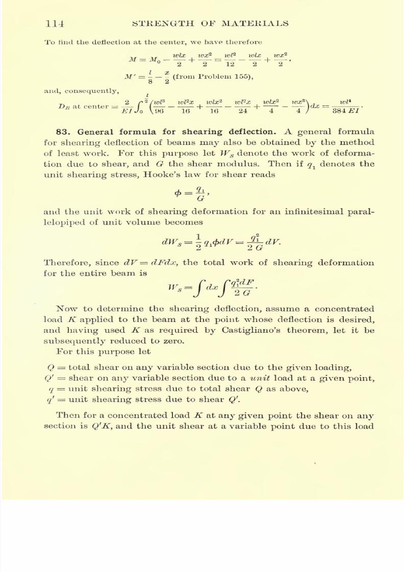
7/30/2019 Textbook on Streng 00 Slo Crich
http://slidepdf.com/reader/full/textbook-on-streng-00-slo-crich 156/433
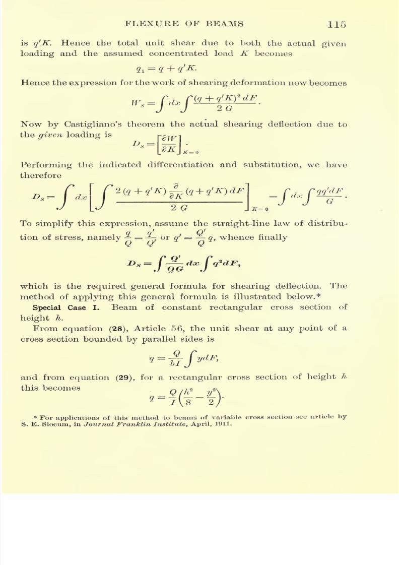
7/30/2019 Textbook on Streng 00 Slo Crich
http://slidepdf.com/reader/full/textbook-on-streng-00-slo-crich 157/433
FLEXURE OF BEAMS 115
is q'K. Hence the total unit shear due to both the actual given
loading and the assumed concentrated load K becomes
Hence the expression for the work of shearing deformation now becomes
Now by Castigliano's theorem the actual shearing deflection due to
the given loading is
Performing the indicated differentiation and substitution, we have
therefore
= dx
/ 20
To simplify this expression, assume the straight-line law of distribu-
tion of stress, namely =,or q
f = q, whence finally
Q Q' Q
which is the required general formula for shearing deflection. The
method of applying this general formula is illustrated below.*
Special Case I. Beam of constant rectangular cross section of
height h.
From equation (28), Article 56, the unit shear at any point of a
cross section bounded by parallel sides is
q=i
and from equation (29),for a rectangular cross section of lieight li
this becomes O /k2
12\
I \ 8 2 /\ /
* For applications of this method to beams of variable cross section see article by
S. E. Slocum, in Journal Franklin Institute, April, 1911.
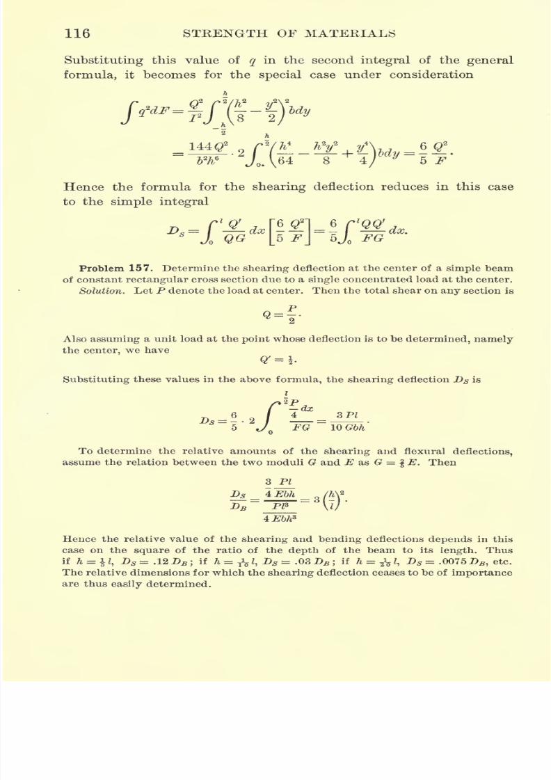
7/30/2019 Textbook on Streng 00 Slo Crich
http://slidepdf.com/reader/full/textbook-on-streng-00-slo-crich 158/433
116 STRENGTH OF MATERIALS
Substituting this value of q in the second integral of the general
formula, it becomes for the special case under consideration
f)1 />2/I,
^-/-144#
2
"8
Hence the formula for the shearing deflection reduces in this case
to the simple integral
Problem 157. Determine the shearing deflection at the center of a simple beam
of constant rectangular cross section due to a single concentrated load at the center.
Solution. Let P denote the load at center. Then the total shear on any section is
Also assuming a unit load at the point whose deflection is to be determined, namely
the center, we have
Substituting these values in the above formula, the shearing deflection DS is
i
. n . 4^ ZPlJL)s = -
FG WGbh
To determine the relative amounts of the shearing and flexural deflections,
assume the relation between the two moduli G and E as G = % E. Then
3 PI
4:Ebh
4Ebh*='@
Hence the relative value of the shearing and bending deflections depends in this
case on the square of the ratio of the depth of the beam to its length. Thus
if h = $l, Ds = .12DB ;if h = ^l, Ds = .03 AB; if h =
-fol,Ds = .0075Dfi ,
etc.
The relative dimensions for which the shearing deflection ceases to be of importance
are thus easily determined.
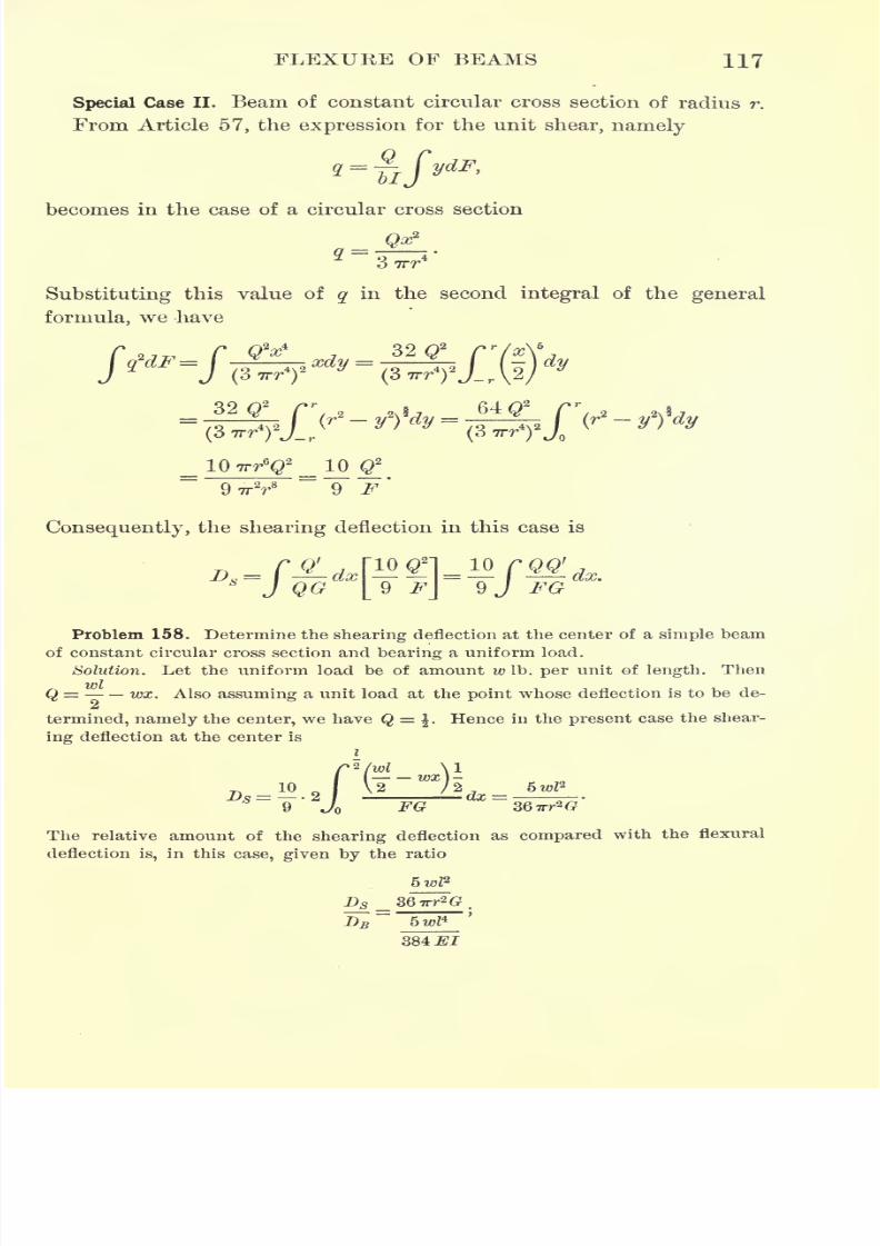
7/30/2019 Textbook on Streng 00 Slo Crich
http://slidepdf.com/reader/full/textbook-on-streng-00-slo-crich 159/433
7/30/2019 Textbook on Streng 00 Slo Crich
http://slidepdf.com/reader/full/textbook-on-streng-00-slo-crich 160/433
118 STRENGTH OF MATERIALS
or assuming, as above, that G = \E and denoting the depth of the beam by h = 2 r,
this becomes
>.s 5
For a circular cross section, therefore, the shearing deflection is of less relative im-
portance for a given ratio of depth to length than for a rectangular cross section.
Thus, if h = ^ I,Ds = .016 D
,etc.
EXERCISES ON CHAPTER IV
Problem 159. In building construction the maximum allowable deflection for
plastered ceilingsis
^of
the span. Afloor is
supported on2 in.
x 10in.
woodenjoists, 14 ft. span and spaced 16 in. apart on centers. Find the maximum load
per square foot of floor surface in order that the deflection may not exceed the
amount specified.
Problem 160. Determine the proper spacing center to center for 12-in. steel I-
beams weighing 35 Ib./ft. for a span of 20 ft. and a uniform floor load of 100 lb./ft.2
in order that the deflection shall not exceed^ of the span.
Problem 161. One end of a beam is built into a wall and the other end is sup-
ported at the same level by a post 12 ft. from the wall. The beam carries a uniform
load of 100 Ib.
perlinear foot. Find the
positionand amount of the maximum
moment and also of the maximum deflection.
Problem 162. One end of a beam is built into a wall and the other end rests
on a prop 20 ft. from the wall, at the same level. The beam bears a concentrated
load of 1 ton at a point 8 ft. from the wall. Find the position and amount of the
maximum moment and also of the maximum deflection.
Problem 163. A simple beam of length I carries a distributed load which varies
uniformly from at one end to w Ib. per unit of length at the other. Find the
maximum deflection.
HINT. Note that in the notation of Article 67,
d*yEl - = load per unit length,
dx*
EI^ = shear,dx3
d2y
El- moment,dx2
EI = EIx slope of elastic curve,
dx
Ely = El x deflection.
In the present case, taking the origin at the light end,
dx* I
which may be integrated to obtain the deflection.
7/30/2019 Textbook on Streng 00 Slo Crich
http://slidepdf.com/reader/full/textbook-on-streng-00-slo-crich 161/433
FLEXURE OF BEAMS 119
Problem 164. A beam of uniform strength is one whose moment of resistance
is in the same constant ratio to the bending moment throughout, so that the skin
stress is constant.
Show that in order for a cantilever bearing a single concentrated load at the
end to be of uniform strength, if the depth is constant, the plan of the beam mustbe triangular ;
whereas if the breadth is constant, the side elevation of the beam
must be parabolic.
Problem 165. A structural steel shaft 8 in. in diameter and 5 ft. long between
bearings carries a 25-ton flywheel midway between the bearings. Find the maximum
deflection of the shaft, considering it as a simple beam.
Problem 166. A wrought-iron bar 2 in. square is bent to a right angle 4 ft.
from one end. The other end is then imbedded in a concrete block so that it stands
upright with the 4 ft. length horizontal. If the upright projects 12 ft. above the con-
crete and a load of 300 Ib.is
hung at the end of the horizontal arm, find thedeflection at the end of this arm.
Problem 167. A cantilever of length I is loaded uniformly. At what point of
its length should a prop be placed, supporting the beam at the same level as the
fixed end, in order to reduce the bending stress as much as possible, and what
proportion of the load is then carried by the prop ?
Problem 168. A continuous beam extends over three spans of 20 ft., 40 ft., and
30 ft., and carries uniform loads of 3, 1, and 2 tons per linear foot on the three
spans respectively. Find the danger sections and the reactions of the supports.
Problem 169.
A carriage springis
2|ft.
longand is built
upof steel leaves
each 2 in. wide and f in. thick. How many leaves are required to carry a central
load of 1000 Ib. with a factor of safety of 4, and what is the deflection under
this load?
HINT. Consider the material spread out in the form of a triangle of constant
depth | in. and varying width, fixed at the base and carrying the load at the apex.
Also compare with Problem 164.

7/30/2019 Textbook on Streng 00 Slo Crich
http://slidepdf.com/reader/full/textbook-on-streng-00-slo-crich 162/433
CHAPTER V
COLUMNS AND STRUTS
84. Nature of compressive stress. When a prismatic piece of
length equal to several times its breadth is subjected to axial com-
pression it is called a column, or strut, the word " column"
being used to
designate a compression member placed vertically and bearing a static
load;
all other compression members being called struts.
If the axis of a column or strut is not perfectly straight, or if the
load is not applied exactly at the centers of gravity of its ends, a
bending moment is produced which tends to make the column deflect
sideways, or "buckle." The same is true if the material is not per-
fectly homogeneous, causing certain parts to yield more than others.
Such lateral deflection increases the bending moment, and conse-
quently increases the tendency to buckle. A compression member is,
therefore, in a different condition of equilibrium from one subjected
to tension, for in the latter any deviation of the axis from a straight
line tends to be diminished by the stress instead of increased.
The oldest theory of columns is due to Euler, and his formula is
still the standard for comparison. Euler's theory, how-
ever, is based upon the assumptions that the column is
i
perfectly straight, the material perfectly homogeneous,
and the load exactly centered at the ends, assump-
tions which are never exactly realized. For practical
purposes, therefore, it has been found necessary to
modify Euler's formula- in such a way as to bring it
into accord with the results of actual experiments, as
X explained in the following articles.
85. Euler's theory of long columns. Consider a long
column subjected to axial loading, and assume that
the column is perfectly straight and homogeneous, and
that the load is applied exactly at the centers of gravity of its ends.
120
7/30/2019 Textbook on Streng 00 Slo Crich
http://slidepdf.com/reader/full/textbook-on-streng-00-slo-crich 163/433
COLUMNS AND STRUTS 121
Assume also that the ends of the column are free to turn about their
centers of gravity, as would be the case, for example, in a column
with round or pivoted ends.
Now suppose that the column is bent sideways by a lateral force,
and let P be the axial load which is just sufficient to cause the col-
umn to retain this lateral deflection when the lateral force is removed.
Let OX and Y be the axes of X and Y respectively (Fig. 92). Then
if y denotes the deflection of a point C at a distance x from 0, the
moment at C is M= Py. Therefore the differential equation of the
elastic curve assumed by the center line of the column is
which may be written
dy?
dy*
To integrate this differential equation, multiply by 2-J-
Thendx
2
^+2P
^ =dx2 dx El dx
and integrating each term,
where Clis a constant of integration. This equation can now be written
P~y
Integrating again,
where <72is also a constant of integration ;
whence
y =
* This is called an integrating factor and makes each term a perfect differential. See
Granville's Calculus, pp. 438, 444.
7/30/2019 Textbook on Streng 00 Slo Crich
http://slidepdf.com/reader/full/textbook-on-streng-00-slo-crich 164/433
122 STRENGTH OF MATERIALS
or, expanding,
xEic r / \
P \
y =
^-^sin
l
x
*\Jjj}
cos
^+ cos lx
xl-^)sin C, |.
Now for convenience let the constants in this integral be denoted
by A, B, and C respectively ;that is to say, let
I Tf T/~i I ~t? TC* I T*
IJ^J.G 1~ ^ L&lCj . ^ _ I -r
Then the general integral becomes
y = A sin (?# + B cos Cte.
At the ends and JT, where x = and/, y = 0. Substituting these
values in the above integral,
-6 = 0, and ^4 sin Cl = 0.
Since ^4 and B cannot both be zero, sin Cl =;whence
Cl = sin^O = XTT,
where X is an arbitrary integer. Now let X take the smallest value
possible, namely 1, and substitute for C its value. Then
whence
(48) *which is Euler's formula for long columns.
Under the load P given by this formula the column is in neutral
equilibrium ;that is to say, the load P is just sufficient to cause it
to retain any lateral deflection which may be given to it. For this
reason P is called the critical load. If the load is less than this
critical value, the column is in stable equilibrium, and any lateral
deflection will disappear when its cause is removed. If the load
exceeds this critical value, the column is in unstable equilibrium, and
the slightest lateral deflection will rapidly increase until rupture
occurs.
86. Columns with one or both ends fixed. The above deduction
of Euler's formula is based on the assumption that the ends of the
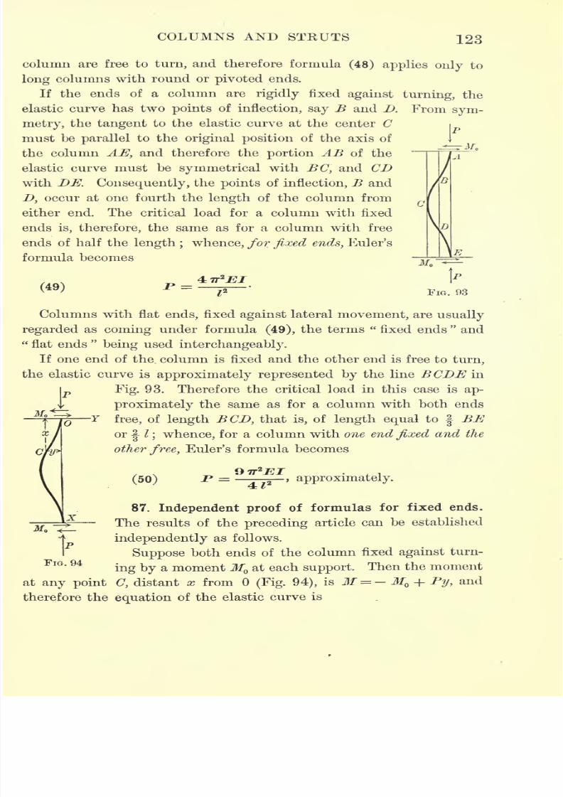
7/30/2019 Textbook on Streng 00 Slo Crich
http://slidepdf.com/reader/full/textbook-on-streng-00-slo-crich 165/433
COLUMNS AND STRUTS 123
column are free to turn, and therefore formula (48) applies only to
long columns with round or pivoted ends.
If the ends of a column are rigidly fixed against turning, the
elastic curve has two points of inflection, say B and D. From sym-
metry, the tangent to the elastic curve at the center C
must be parallel to the original position of the axis of
the column AE, and therefore the portion AB of the
elastic curve must be symmetrical with BC, and CD
with DE. Consequently, the points of inflection, B and
D, occur at one fourth the length of the column from
either end. The critical load for a column with fixed
ends is, therefore, the same as for a column with free
ends of half the length ; whence, for fixed ends, Euler's
formula becomes
(49) _P =FIG. 93
Columns with flat ends, fixed against lateral movement, are usually
regarded as coming under formula (49), the terms "fixed ends
"and
"flat ends
"
being used interchangeably.
If one end of the. column is fixed and the other end is free to turn,
the elastic curve is approximately represented by the line BCDE in
|pFig. 93. Therefore the critical load in this case is ap-
I proximately the same as for a column with both ends
-Y free, of length BCD, that is, of length equal to f BEor
|^I
; whence, for a column with one end fixed and the
other free, Euler's formula becomes
(50) P = approximately.
87. Independent proof of formulas for fixed ends.
The results of the preceding article can be established
independently as follows.
Suppose both ends of the column fixed against turn-
ing by a moment MQat each support. Then the moment
at any point C, distant x from(Fig. 94), is M = - M + Py, and
therefore the equation of the elastic curve is
FIG. 94
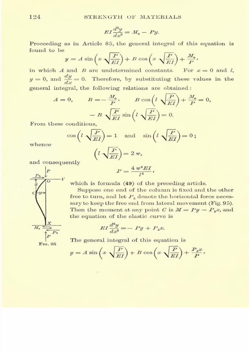
7/30/2019 Textbook on Streng 00 Slo Crich
http://slidepdf.com/reader/full/textbook-on-streng-00-slo-crich 166/433
124 STRENGTH OF MATERIALS
Proceedingas in Article
85,the
general integralof this
equationis
found to be
y A sin(x
V
-
in which A and 5 are undetermined constants. For x = and /,
y = 0, and -^ = 0. Therefore, by substituting these values in the
general integral, the following relations are obtained :
p / Psin I J )-0.
From these conditions,
cos
(l
\l^}= 1
andsin
(KI^)=
;
whence
and consequently
FIG. 95
which is formula (49) of the preceding article.
Suppose one end of the column is fixed and the other
free to turn, and let Phdenote the horizontal force neces-
sary to keep the free end from lateral movement (Fig. 95).
Then the moment at any point C is M = Py Phx, and
the equation of the elastic curve is
The general integral of this equation is
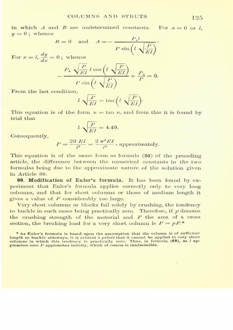
7/30/2019 Textbook on Streng 00 Slo Crich
http://slidepdf.com/reader/full/textbook-on-streng-00-slo-crich 167/433
COLUMNS AND STRUTS 125
in which A and B are undetermined constants. For x = or lt
y = ;whence
B = and A =-
For x =I,~ =
;whence
From the last condition,
This equation is of the form u = tan u, and from this it is found by
trial that
= 4.49.
Consequently,
20 El 2 -rr^EIP = = , approximately.
V v
This equation is of the same form as formula (50) of the preceding
article, the difference between the numerical constants in the two
formulas being due to the approximate nature of the solution given
in Article 86.
88. Modification of Euler's formula. It has been found by ex-
periment that Euler's formula applies correctly only to very long
columns, and that for short columns or those of medium length it
gives a value of P considerably too large.
Very short columns or blocks fail solely by crushing, the tendency
to buckle in such cases being practically zero. Therefore, if p denotes
the crushing strength of the material and F the area of a cross
section, the breaking load for a very short column is P = pF.*
* As Euler's formula is based upon the assumption that the column is of sufficient
length to buckle sideways, it is evident a priori that it cannot be applied to very short
columns in which this tendency is practically zero. Thus, in formula (48), as I ap-
proaches zero P approaches infinity, which of course is inadmissible.
7/30/2019 Textbook on Streng 00 Slo Crich
http://slidepdf.com/reader/full/textbook-on-streng-00-slo-crich 168/433
126 STRENGTH OF MATERIALS
For columns of ordinary length, therefore, the load P must lie
somewhere between pF and the value given by Euler's formula.
Consequently, to obtain a general formula which shall apply to
columns of any length, it is only necessary to express a continuous2jfij
relation between pF and - Such a relation is furnished by the
equation
(51)!>=
1+pF
For when / = 0, P = pF, and when / becomes very large P approaches2
37*7"
the.value Moreover, for intermediate values of I this formulaL
gives values of P considerably less than given by Euler's formula, thus
agreeing more closely with experiment.
89. Rankine's formula. Although the above modification of
Euler's formula is an improvement on the latter, it does not yet
agree closely enough
with
experiment
to be entirelysatisfactory.
The reason for the discrepancy between the results given by this
formula and those obtained from actual tests is that the assumptions
upon which the formula is based, namely, that the column is perfectly
straight, the material perfectly homogeneous, and the load applied
exactly at the centers of gravity of the ends, are never actually
realized in practice.
To obtain a more accurate formula, twoempirical
constants will
be introduced into equation (51). Thus, for fixed ends, let
(52) P =y\
2
v .
where/and g are arbitrary constants to be determined by experiment,
and t is the least radius of gyration of a cross section of the column.
This formula has been obtained in different ways by Gordon, Ran-
kine, Navier, and Schwarz.* Among German writers it is known as
* Rankine's formula can be derived independently of Euler's formula either by
assuming that the elastic curve assumed by the center line of the column is a sinusoid,
or by assuming that the maximum lateral deflection D at the center of the column is
72
given by the expression D = n ,where I is the length of the column, b its least width,
and n an empirical constant.&
7/30/2019 Textbook on Streng 00 Slo Crich
http://slidepdf.com/reader/full/textbook-on-streng-00-slo-crich 169/433
COLUMNS AND STEUTS 127
Schwarz' formula, whereas in English and American text-books it is
called Rankine's formula.
For / = 0, P =gF, and since short blocks fail by crushing, g is
therefore the ultimate compressive strength of the material.
For different methods of end support Eankine's formula takes
the following forms.
Flat ends, |=- _.
(fixed in direction) 1 _|_f I -
Roundends,
(direction not fixed) 1 _i_ A fl_J
Hinged ends,
(position fixe
direction)
One end flat and the other round,
/
,. -
direction)
(position fixed, but nof.
-^1 i O -f IL ~T &J (
~
90. Values of the empirical constants in Rankine's formula.
The values of the empirical constants, / and g, in Eankine's formula
have been experimentally determined by Hodgkinson and Christie
with the following results.
For hard steel, g = 69,000 lb./in.2, / =
For mild steel, g = 48,000 lb./in.2
, / =30,000
For wrought iron, g= 36,000 lb./in.
2
, / =^^For cast iron, g
= 80,000 lb./in.2
, / =
For timber, g= 7,200 lb./in.2
, / =
These constants were determined by experiments upon columns for
which 20<-<200, and therefore can only be relied upon to
7/30/2019 Textbook on Streng 00 Slo Crich
http://slidepdf.com/reader/full/textbook-on-streng-00-slo-crich 170/433
128 STRENGTH OF MATERIALS
furnish reliable results when the dimensions of the column lie within
these limits.
As a factor of safety to be used in applying the formula, Rankine
recommended 10 for timber, 4 for iron under dead load, and 5 for
iron under moving load.
Problem 170. A solid, round, cast-iron column with flat ends is 15 ft. long and
6 in. in diameter. What load may be expected to cause rupture ?
Problem 171. A square wooden post 12 ft. long is required to support a load
of 15 tons. With a factor of safety of 10, what must be the size of the post ?
Problem 172. Two medium steel Cambria I-beams, No. B 25, weighing 25.25
lb./ft., are joined by lattice work to form a column 25 ft. long. How far apart
must the beams be placed, center to center, in order that the column shall be of
equal strength to resist buckling in either axial plane ?
Problem 173. Four medium steel Cambria angles, No. A 101, 3 in. by 5 in. in
size, have their 3-in. legs riveted to af-in. plate so as to form an I-shaped built
column. How wide must the plate be in order that the column shall be of equal
strength to resist buckling in either axial plane ?
91. Johnson's parabolic formula. From the manner in which
equation (51) was obtained and afterward modified by the intro-
duction of the empirical constants / andg, it is clear that Rankine's
formula satisfies the requirements for very long or very short col-
umns, while for those of intermediate length it gives the average
values of experimental results. A simple formula which fulfills
these same requirements has been given by Professor J. B. Johnson,
and is called Johnson's parabolic formula.
If equation (52) is written
and then y is written for p, and x for -> Rankine's formula becomes
t
y
For this cubic equation Johnson substituted the parabola
y = S - ear2
,
in which x and y have the same meaning as above, and S and e are
empirical constants. The constants 8 and e are then so chosen that
7/30/2019 Textbook on Streng 00 Slo Crich
http://slidepdf.com/reader/full/textbook-on-streng-00-slo-crich 171/433
COLUMNS AND STRUTS 129
the vertex of this parabola is at the elastic limit of the material
on the axis of loads (or F-axis), and the parabola is also tangent
to Euler's curve. In this way the formula is made tosatisfy the
theoretical requirements for very long or very short columns, and
for those of intermediate length it is found to agree closely with
experiment.
For different materials and methods of end support Johnson's
parabolic formulas, obtained as above, are as follows :
KIND OF COLUMN
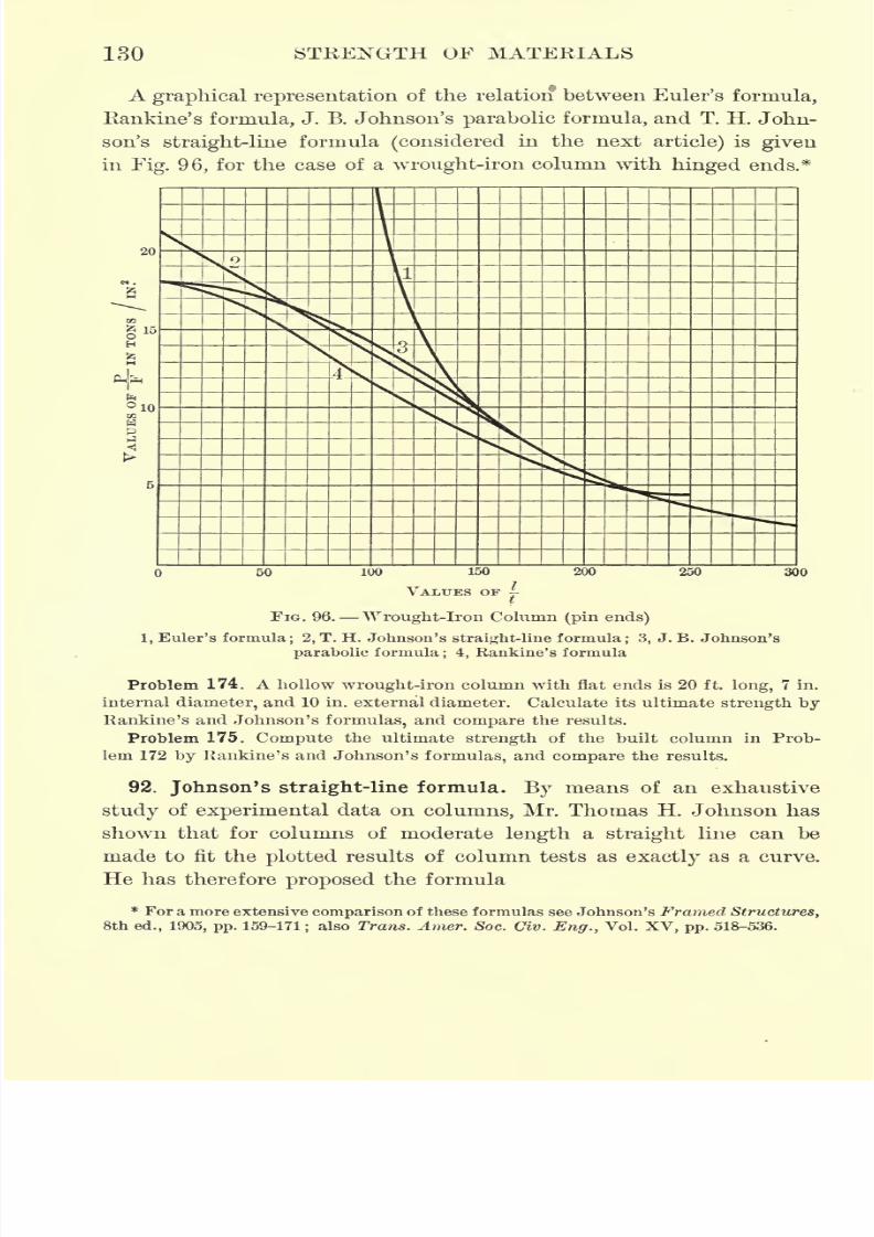
7/30/2019 Textbook on Streng 00 Slo Crich
http://slidepdf.com/reader/full/textbook-on-streng-00-slo-crich 172/433
130 STRENGTH OF MATERIALS
A graphical representation of the relation between Euler's formula,
Rankine's formula, J. B. Johnson's parabolic formula, and T. H. John-
son's straight-line formula (considered in the next article) is given
in Fig. 96, for the case of a wrought-iron column with hinged ends.*
300
FIG. 96. Wrought-iron Column (pin ends)
1, Euler's
formula;2, T. H. Johnson's
straight-line formula;3, J. B. Johnson's
parabolic formula; 4, Rankine's formula
Problem 174. A hollow wrought-iron column with flat ends is 20 ft. long, 7 in.
internal diameter, and 10 in. external diameter. Calculate its ultimate strength by
Rankine's and Johnson's formulas, and compare the results.
Problem 175. Compute the ultimate strength of the built column in Prob-
lem 172 by Rankine's and Johnson's formulas, and compare the results.
92. Johnson's straight-line formula. By means of an exhaustive
study of experimental data on columns, Mr. Thomas H. Johnson has
shown that for columns of moderate length a straight line can be
made to fit the plotted results of column tests as exactly as a curve.
He has therefore proposed the formula
* For a more extensive comparison of these formulas see Johnson's Framed Structures,
8th ed., 1905, pp. 159-171; also Trans. Artier. Soc. Civ. Eng., Vol. XV, pp. 518-536.
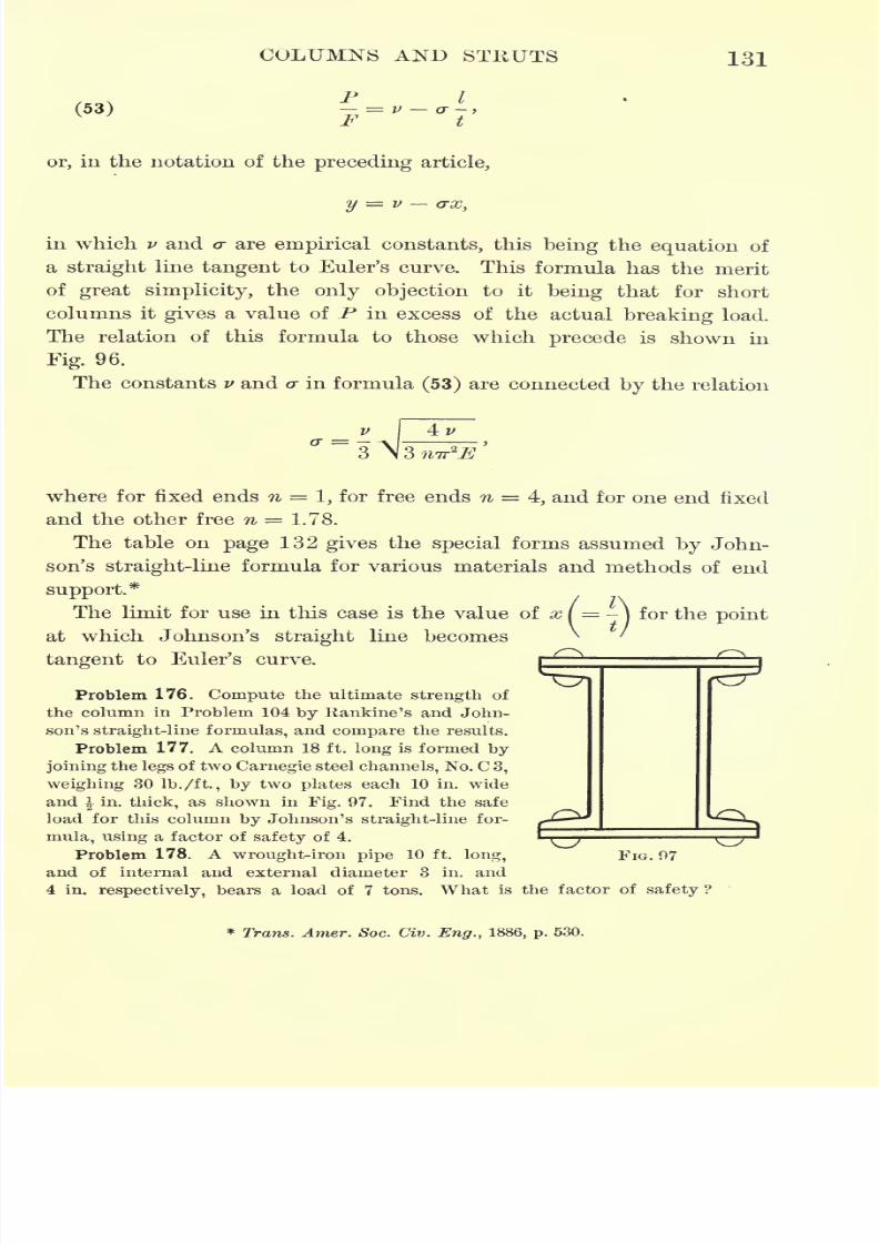
7/30/2019 Textbook on Streng 00 Slo Crich
http://slidepdf.com/reader/full/textbook-on-streng-00-slo-crich 173/433
COLUMNS AND STRUTS 131
(53)
P I= V (7
F t
or, in the notation of the preceding article,
in which v and <r are empirical constants, this being the equation of
a straight line tangent to Euler's curve. This formula has the merit
of great simplicity, the only objection to it being that for short
columns it
gives
a value of P in excess of the actual
breakingload.
The relation of this formula to those which precede is shown in
Fig. 96.
The constants v and cr in formula (53) are connected by the relation
where for fixed ends n = 1, for free ends n 4, and for one end fixed
and the other free n = 1.78.
The table on page 132 gives the special forms assumed by John-
son's straight-line formula for various materials and methods of end
support.*
The limit for use in this case is the value of x I = -)
for the point
at which Johnson's straight line becomes
tangent to Euler's curve.
^roblem 176. Compute the ultimate strength of
the column in Problem 104 by Rankine's and John-
son's straight-line formulas, and compare the results.
Problem 177. A column 18 ft. long is formed by
joining the legs of two Carnegie steel channels, No. C 3,
weighing 30 lb./ft, by two plates each 10 in. wide
and in. thick, as shown in Fig. 97. Find the safe
load for this column by Johnson's straight-line for-
mula, using a factor of safety of 4.
Problem 178. A wrought-iron pipe 10 ft. long,
and of internal and external diameter 3 in. and
4 in. respectively, bears a load of 7 tons. What is the factor of safety ?
FIG. 97
* Trans. Amer. Soc. Civ. Eng., 1886, p. 530.
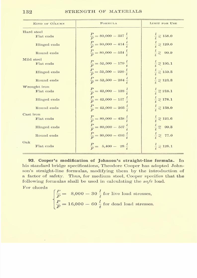
7/30/2019 Textbook on Streng 00 Slo Crich
http://slidepdf.com/reader/full/textbook-on-streng-00-slo-crich 174/433
132 STRENGTH OF MATERIALS
KIND OF COLUMN
7/30/2019 Textbook on Streng 00 Slo Crich
http://slidepdf.com/reader/full/textbook-on-streng-00-slo-crich 175/433
COLUMNS AND STRUTS 133
For posts
^ = 7,000- 40 - for live load stresses,F t
j,
= 14,000 - 80 - for dead load stresses,
P I-
10,000 60 - for wind stresses._r t
For lateral struts
~ = 9,000- 50 - for initial stresses.
By initial stress in the last formula is meant the stress due to the
adjustment of the bridge members during construction.
Problem 179. What must be the size of a square steel strut 8 ft. long, to trans-
mit a load of 6 tons with safety ?
Problem 180. Design a column 16 ft. long to be formed of two channels joined
by two plates and to support a load of 20 tons with safety.
Problem 181. Using Cooper's formula for live load, design the inclined endpost of a bridge which is 25 ft. long and bears a load of 30 tons, 'the end post to be
composed of four angles, a top plate, and two side plates.
94. Beams of considerable depth. When narrow beams of consider-
able depth are subjected to compression, as, for example, in a deck
plate girder bridge, the strain is similar to that in a column. For a
narrow, deep beam the inertia ellipse is greatly elongated, and conse-
quently the radius of gyration relative to a line forming a small angle
with the horizontal is considerably less than the semi-major axis of
the ellipse. Therefore, if the beam is thrown slightly out of the ver-
tical by the unequal settling of its supports, or by any other cause,
such inclination results in a notable decrease in its resistance. Since
it is impossible to make allowances for such accidental reductions of
strength, beams of great depth or very thin web should be avoided.
95. Eccentrically loaded columns. In a column carrying an eccen-
tric load, as, for example, a column carrying a load on a bracket, or
the post of a crane, there is a definite amount of bending stress due
to the eccentricity of the load in addition to the column stress. As
the nature of column stress is such that it is impossible to deter-
mine its amount, the simplest method of handling a problem of this
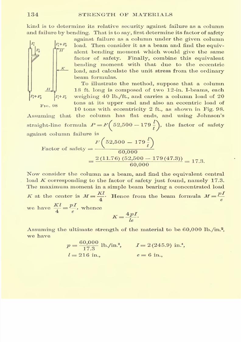
7/30/2019 Textbook on Streng 00 Slo Crich
http://slidepdf.com/reader/full/textbook-on-streng-00-slo-crich 176/433
134 STRENGTH OF MATERIALS
H\
pj+P
kind is to determine its relative security against failure as a column
and failure by bending. That is to say, first determine its factor of safety
against failure as a column under the given column
load. Then consider it as a beam and find the equiv-
alent bending moment which would give the same
factor of safety. Finally, combine this equivalent
bending moment with that due to the eccentric
load, and calculate the unit stress from the ordinary
beam formulas.
To illustrate the method, suppose that a column
18 ft. long is composed of two 12-in. I-beams, each
weighing 40 lb./ft., and carries a column load of 20
tons at its upper end and also an eccentric load of
10 tons with eccentricity 2 ft., as shown in Fig. 98.
Assuming that the column has flat ends, and using Johnson's
straight-line formulaP=jP( 52,500 179 -\ the factor of safety
against column failure is
^52,500-179 -\
Factor of safety,6Q?000
_ 2(11.76) (52,500-
179(47.3)) _60,000
Now consider the column as a beam, and find the equivalent central
load K corresponding to the factor of safety just found, namely 17.3.
The maximum moment in a simple beam bearing a concentrated load
FIG.
K at the center is M=4
Hence from the beam formula M
we, Kl pi .
have -=-, whence4 e
le
Assuming the ultimate strength of the material to be 60,000 lb./in.2,
we have
60,000P ~~
17.3
= 216 in.,
lb./in.2
,1= 2 (245.9) in.
4
,
e = 6 in.,
7/30/2019 Textbook on Streng 00 Slo Crich
http://slidepdf.com/reader/full/textbook-on-streng-00-slo-crich 177/433
COLUMNS AND STKUTS 135
and inserting these values, the equivalent load K is found to be
4 x 60,000 x 491.8
17.3 x 216 x 6
Now the eccentric load P acting parallel to the axis of the column
produces the same bending effect as a horizontal reaction H at either
end, where HI = Pd. The bending moment at the center, due to a
TT7
reaction H perpendicular to the axis of the beam, is, however,
Hence the total
equivalentmoment at the center now becomes
M- + - ^-
_5220x 216 20,000 x 24
4 2
= 521,880 in. Ib.
Consequently, the maximum unit stress in the member becomes
M
521,880 , Q ,_ ., ..2
==
^l96-==63671b-/in-
which corresponds to a factor of safety of about 9.
If this factor of safety is larger than desired, assume a smaller
I-beam and repeat the calculations.
A method substantially equivalent to the above is to assume that
the stress in a column is represented by the empirical factor in the
column formula used. Thus for a short block, the actual compressive
stress p is given by the relation P = pF, whereas in the column
formula used above, namely P = W52,500 179 - ), the stress p is
replaced by the empirical factor 52,500 179-. Consequently, the
fraction
52,500-179-t
7/30/2019 Textbook on Streng 00 Slo Crich
http://slidepdf.com/reader/full/textbook-on-streng-00-slo-crich 178/433
136 STRENGTH OF MATERIALS
where ucdenotes the ultimate compressive strength of the material,
represents the reduction in strength of the member due to its slim-
ness and method of loading ; or, what amounts to the same thing, the
equivalent unit stress in the column is
52,500- 179-t
t
Applying this method to the numerical problem given above, we
have ^=23.52,
- = 47.3, and60,000
52,500 -179179 x 47.3
Hence the equivalent stress in the column is
30 x 2000Pe
23.52
x 1.36 = 3470 lb./in.s
Also, the bending stress, produced by the eccentricity of the load, is
Consequently, by this method, the total stress in the column is found
3470 + 2928 = 6398 lb./in.
2
If a formula of the Rankine-Gordon type is used, namely,
P_ 9
the equivalent stress pein the column, due to the given load P, is
u.
9
where ucdenotes the ultimate compressive strength of the material,
as above.
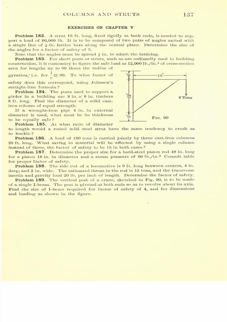
7/30/2019 Textbook on Streng 00 Slo Crich
http://slidepdf.com/reader/full/textbook-on-streng-00-slo-crich 179/433
COLUMNS AND STKUTS 137
EXERCISES ON CHAPTER V
Problem 182. A strut 16 ft. long, fixed rigidly at both ends, is needed to sup-
port a loadof
80,000Ib. It is to
be composedof two
pairsof
angles united witha single line of -in. lattice bars along the central plane. Determine the size of
the angles for a factor of safety of 5.
Note that the angles must be spread in. to admit the latticing.
Problem 183. For short posts or struts, such as are ordinarily used in building
construction, it is customary to figure the safe load as 12,000 lb./in.2 of cross-section
area for lengths up to 90 times the radius of
gyration,* i.e. for -^90. To what factor of sp H= 141
S'Toiis
FIG. 99
safety does this correspond, using Johnson'sstraight-line formula ?
Problem 184. The posts used to support a
girder in a building are 8 in. x 8 in. timbers
8 ft. long. Find the diameter of a solid cast-
iron column of equal strength.
If a wrought-iron pipe 4 in. in external
diameter is used, what must be its thickness
to be equally safe ? _
Problem185. At what ratio of diameter
to length would a round mild steel strut have the same tendency to crush as
to buckle?
Problem 186. A load of 100 tons is carried jointly by three cast-iron columns
20 ft. long. What saving in material will be effected by using a single column
instead of three, the factor of safety to be 15 in both cases ?
Problem 187. Determine the proper size for a hard-steel piston rod 48 in. long
for a piston 18 in. in diameter and a steam pressure of 80 lb./in.2 Consult table
for proper factor of safety.
Problem 188. The side rod of a locomotive is 9 ft.
longbetween centers, 4 in.
deep, and 2 in. wide. The estimated thrust in the rod is 12 tons, and the transverse
inertia and gravity load 20 Ib. per inch of length. Determine the factor of safety.
Problem 189. The vertical post of a crane, sketched in Fig. 99, is to be made
of a single I-beam. The post is pivoted at both ends so as to revolve about its axis.
Find the size of I-beam required for factor of safety of 4, and for dimensions
and loading as shown in the figure.
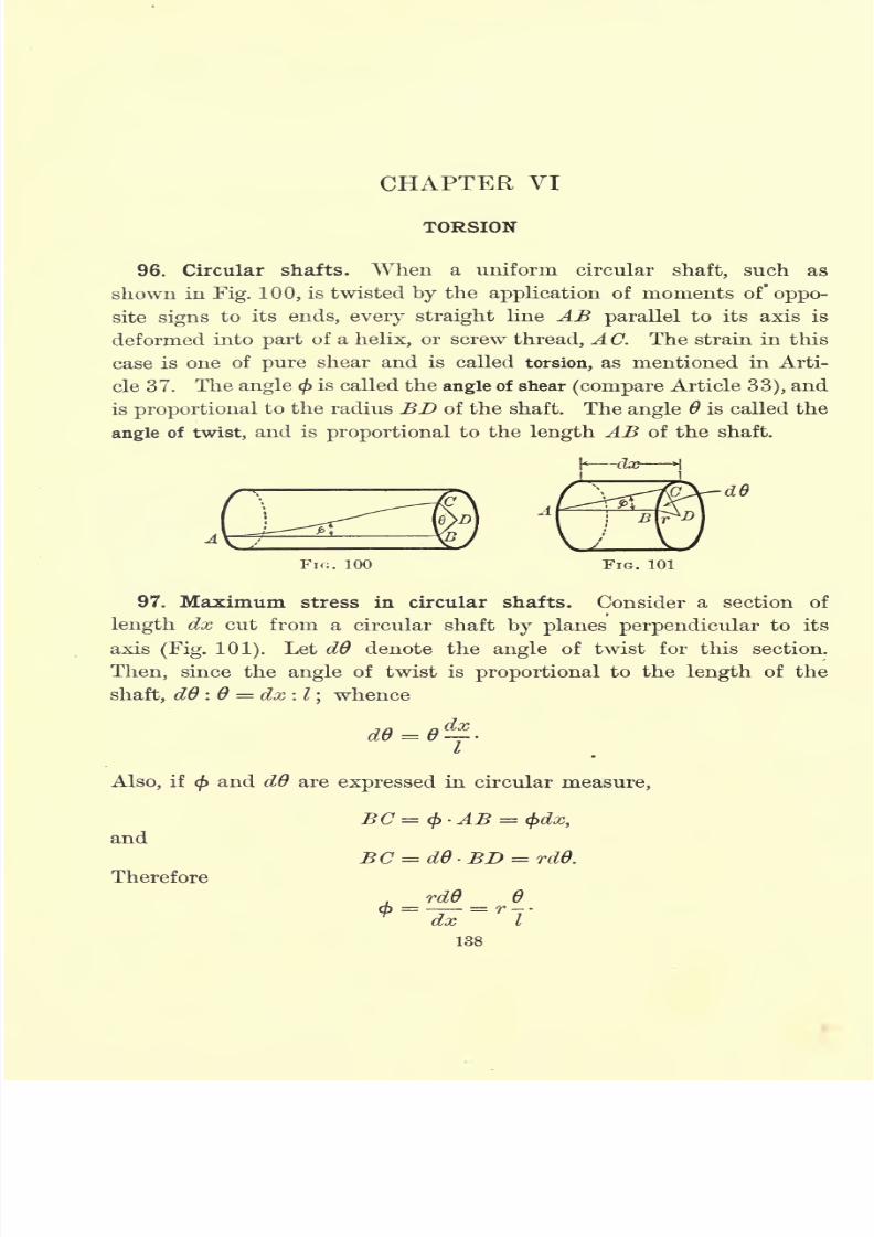
7/30/2019 Textbook on Streng 00 Slo Crich
http://slidepdf.com/reader/full/textbook-on-streng-00-slo-crich 180/433
CHAPTER VI
TORSION
96. Circular shafts. When a uniform circular shaft, such as
shown in Fig. 100, is twisted by the application of moments of" oppo-
site signs to its ends, every straight line AB parallel to its axis is
deformed into part of a helix, or screw thread, A C. The strain in this
case is one of pure shear and is called torsion, as mentioned in Arti-
cle 37. The angle <f>is called the angle of shear (compare Article 33), and
is proportional to the radius BD of the shaft. The angle 6 is called the
angle of twist, and is proportional to the length AB of the shaft.
FIG. 100 FIG. 101
97. Maximum stress in circular shafts. Consider a section of
length dx cut from a circular shaft by planes perpendicular to its
axis (Fig. 101). Let dO denote the angle of twist for this section.
Then, since the angle of twist is proportional to the length of the
shaft, dO : 6 = dx : I;whence
de-eI
'
Also, if $ and dO are expressed in circular measure,
and
Therefore
. rdO 6m = = T
dx I
138
7/30/2019 Textbook on Streng 00 Slo Crich
http://slidepdf.com/reader/full/textbook-on-streng-00-slo-crich 181/433
TOKSION 139
From Hooke's law (Article 33),= G. Hence
9
(54) q = G<t> = i
Therefore q is proportional to r;that is to say, the unit shear is pro-
portional to its distance from the center, being zero at the center
and attaining its maximum value at the circumference.
Ifq' denotes the intensity of the shear at the circumference and
a denotes the radius of the shaft, then the shear q at a distance r
from the center is given by the formula
q'r
Let Mtdenote the external twisting moment. Then, since M
tmust
be equal to the internal moment of resistance,
Mt
t
=CqrdF=
Cr*dF=J aj a
where Ip
is the polar moment of inertia of the section.
For a solid circular shaft of diameter D, Ip
-r
-, and consequently
For a hollow circular shaft of external diameter D and internal
diameter dyIp= ~ (D
4d
4
),and hence
(56) q1 =
98. Angle of twist in circular shafts. From equation (54),
Gr Ga'
Therefore, for a solid circular shaft, from equation (55),
(57) 6.
7/30/2019 Textbook on Streng 00 Slo Crich
http://slidepdf.com/reader/full/textbook-on-streng-00-slo-crich 182/433
140 STRENGTH OF MATERIALS
and for a hollow circular shaft, from equation (56),
If Mtis known and can be measured, equations (57) and
(58)can
be used for determining G. If G is known and 6 measured, these
equations can be used for finding Mt ;in this way the horse power
which a rotating circular shaft is transmitting can be determined.
Problem 190. A steel wire 20 in. long and .182 in. in diameter is twisted by
a moment of 20 in. Ib. The angle of twist is then measured and found to be
9 = 18 31'. What is the value of G determined from this experiment ?
Problem 191. If the angle of twist for the wire in Problem 190 is 6 40, how
great is the torsional moment acting on the wire ?
99. Power transmitted by circular shafts. Let H be the number
of horse power transmitted by the shaft, and n the number of revolu-
tions it makes per minute. Then, if q is the force acting on a particle
at a distance r from the center, the moment of this force is qr, and
consequently the total moment transmitted by the shaft is
Mt
= I qrdF.
Also, the distance traveled by q in one minute is 2 Trrn, and there-
fore the total work transmitted by the shaft is
W= Cz
Since 1 horse power = 33,000 ft. Ib./min. = 396,000 in. Ib./min., the
total work done by the shaft is
W= 396,000 H in. Ib./min.
Therefore
2 irn CrqdF= W= 396,000 H,
2 im,Mt
= 396,000 H-,
.2 Trn
Therefore, if it is required to find the diameter D of a solid circular
shaft which shall transmit a given horse power H with safety, then
from equation (55),^ ^ 16Jff _ 321,000 IT
~
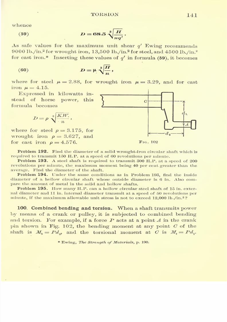
7/30/2019 Textbook on Streng 00 Slo Crich
http://slidepdf.com/reader/full/textbook-on-streng-00-slo-crich 183/433
TORSION 141
whence
(59) Z> = 68.5
.-^
As safe values for the maximum unit shear q1
Ewing recommends
9000 lb./in.2 for wrought iron, 13,500 lb./in.
2 for steel, and 4500 lb./in.2
for cast iron.* Inserting these values ofq'
in formula(59),
it becomes
(60)
where for steel
p 2.88,for
wroughtiron
p=
3.29, andfor
castiron
IJL= 4.15.
Expressed in kilowatts in-
stead of horse power, this
formula becomes
where for steel p= 3.175, for
wrought iron p= 3.627, and
for cast iron p= 4.576.
Problem 192. Find the diameter of a solid wrought-iron circular shaft which is
required to transmit 150 H.P. at a speed of 60 revolutions per minute.
Problem 193. A steel shaft is required to transmit 300 H.P. at a speed of 200
revolutions per minute, the maximum moment being 40 per cent greater than the
average. Find the diameter of the shaft.
Problem 194. Under the same conditions as in Problem 193, find the inside
diameter of a hollow circular shaft whose outside diameter is 6 in. Also com-
pare the amount of metal in the solid and hollow shafts.
Problem 195. How many H.P. can a hollow circular steel shaft of 15 in. exter-
nal diameter and 11 in. internal diameter transmit at a speed of 50 revolutions per
minute, if the maximum allowable unit stress is not to exceed 12,000 lb./in.2 ?
100.
Combined bending andtorsion.
When a shaft transmits powerby means of a crank or pulley, it is subjected to combined bending
and torsion. For example, if a force P acts at a point A in the crank
pin shown in Fig. 102, the bending moment at any point C of the
shaft is Mb= Pd^ and the torsional moment at C is M
t
= Pdr
Ewing, The Strength of Materials, p. 190.
7/30/2019 Textbook on Streng 00 Slo Crich
http://slidepdf.com/reader/full/textbook-on-streng-00-slo-crich 184/433
142 STRENGTH OF MATERIALS
Therefore, if D is the diameter of the shaft at (7, the normal stress
on the extreme fiber due to bending is
_'32Mh
P ~~~'^^>
and the shearing stress on the extreme fiber due to torsion is
= 16Jf,q
"
TrD3
'
There is also a shearing stress of amount P distributed over the
cross section through (7, but since it is zero at the outer fiber, it does
not enter into this calculation.
From Article 26, the values of the principal stresses are
and from Article 28, the maximum or minimum shear is
Inserting in these expressions the values of p and q obtained above,
the principal stresses and the maximum or minimum shear are, in
the present case,
V'Ml + M\) (called Rankine's formula),mill
16</'iiiax
= =*=
-^Ml + Mf (calledGuest's
formula).mill ITI)
The equivalent stress may also be found. Thus, from equation (15),
Article 36, assuming m =3J,
its value is found to be
16 i
pe=
[.7Mb 1.3 VJWrJ + Ml~] (called St. Venant's formula).
It is evident that St. Venant's formula is simply a refinement on
Rankine's, as both give the principal normal stresses, whereas Guest's
formula is essentially different, since it gives shear. Hence in design-
ing members subjected to both bending and torsion, try both Guest's
and Rankine's(or St. Venant's) formulas with the same factor of
safety, and then use whichever gives the larger dimensions to the
construction.
7/30/2019 Textbook on Streng 00 Slo Crich
http://slidepdf.com/reader/full/textbook-on-streng-00-slo-crich 185/433
TORSION 143
Problem 196. A steel shaft 5 in. in diameter is driven by a crank of 12-in.
throw, the maximum thrust on the crank being 10 tons. If the outer edge of the
shaft bearing is 11 in. from the center of the crank pin, what is the equivalent
stress in the shaft at this point ?
Problem 197. A steel shaft 10 ft. long between bearings and 4 in. in diameter
carries a pulley 14 in. in diameter at its center. If the tension in the belt on this
pulley is 250 lb., and the shaft makes 80 revolutions per minute, what is the maxi-
mum stress in the shaft and how many H.P. is it transmitting ?
*101. Resilience of circular shafts. In Article 74 the resilience of
a body was denned as the internal work of deformation. For a solid
circular shaft this internal work is
where Ntis the external twisting moment and 6 is the angle of twist.
From equation (54), 6 = -^ =,and from equation (55),
M= --~-
Gr Ga 16
Therefore the total resilience of the shaft is
2
and consequently the mean resilience per unit of volume is
w - W~*
WI ~V"-TG'
102. Non-circular shafts. The ahove investigation of the distribu-
tion and intensity of torsional stress applies only to shafts of circular
section. Forother forms of cross section the results are
entirelydif-
ferent, each form having its own peculiar distribution of stress.
For any form of cross section whatever, the stress at the boundary
must be tangential. For if the stress is not tangential, it can be
resolved into two components, one tangential and the other normal
to the boundary ;and in Article 23 it was shown that such a normal
component would necessitate forces parallel to the axis of the shaft,
which are excluded by hypothesis.Since the stress at the boundary must be tangential, the circular
section is the only one for which the stress is perpendicular to a
radius vector. Therefore the circular section is the only one to which
the above development applies, and consequently is the only form of
* For a brief course the remainder of this chapter may be omitted.
7/30/2019 Textbook on Streng 00 Slo Crich
http://slidepdf.com/reader/full/textbook-on-streng-00-slo-crich 186/433
144 STEENGTH OF MATERIALS
cross section for which Bernoulli's assumption holds true. That is to
say, the circular section is the only form of cross section which remains
plane under a torsional strain.
The subject of the distribution of stress in non-circular shafts has
been investigated by St. Yenant, and the results of his investigations
are summarized below (Articles 103-106 inclusive).
103. Elliptical shaft. For a shaft the cross section of which is an
ellipse of semi-axes a and b, the maximum stress occurs at the ends
of the minor axis, instead of at the ends of the major axis, as might
be expected. The unit stress at the ends of the minor axis is given
by the formula ,..22 JxL
t
and the angle of twist per unit of length is
The total angle of twist for an elliptical shaft of length I is therefore
Problem 198. The semi-axes of the cross section of an elliptical shaft are 3 in.
and 5 in. respectively. What is the diameter of a circular shaft of equal strength?
104. Rectangular and square shafts. For a shaft of rectangular
cross section the maximum stress occurs at the centers of the longer
sides, its value at these points being
(61) gmax =_ = .68 + .45
in which h is the longer and I the shorter side of the rectangle. The
angle of twist per unit of length is, in this case,
For a square shaft of side b these formulas become
(62)
and
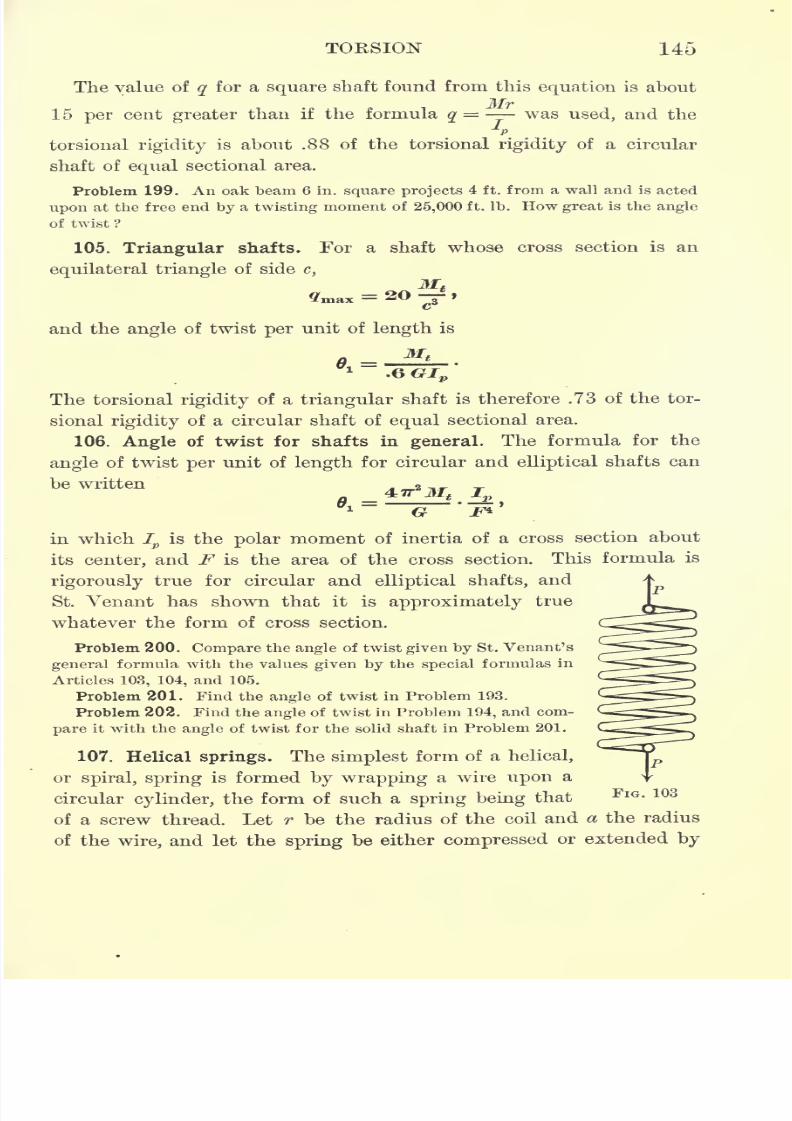
7/30/2019 Textbook on Streng 00 Slo Crich
http://slidepdf.com/reader/full/textbook-on-streng-00-slo-crich 187/433
TORSION 145
The value of q for a square shaft found from this equation is about
Mr15 per cent greater than if the formula q
= was used, and the
p
torsional rigidity is about .88 of the torsional rigidity of a circular
shaft of equal sectional area.
Problem 199. An oak beam 6 in. square projects 4 ft. from a wall and is acted
upon at the free end by a twisting moment of 25,000 ft. Ib. How great is the angle
of twist ?
105. Triangular shafts. For a shaft whose cross section is an
equilateral triangle of side c,
M.= 20
and the angle of twist per unit of length is
The torsional rigidity of a triangular shaft is therefore .73 of the tor-
sional rigidity of a circular shaft of equal sectional area.
106. Angle of twist for shafts in general. The formula for the
angle of twist per unit of length for circular and elliptical shafts can
be written
=1 G
in which Ip
is the polar moment of inertia of a cross section about
its center, and F is the area of the cross section. This formula is
rigorously true for circular and elliptical shafts, andSt. Venant has shown that it is approximately true
whatever the form of cross section.
Problem 200. Compare the angle of twist given by St. Venant's
general formula with the values given by the special formulas in
Articles 103, 104, and 105.
Problem 201. Find the angle of twist in Problem 193.
Problem 202. Find the angle of twist in Problem 194, and com-
pare it with the angle of twist for the solid shaft in Problem 201.
107. Helical springs. The simplest form of a helical,
orspiral, spring is formed by wrapping a wire upon a
circular cylinder, the form of such a spring being that
of a screw thread. Let r be the radius of the coil and a the radius
of the wire, and let the spring be either compressed or extended by
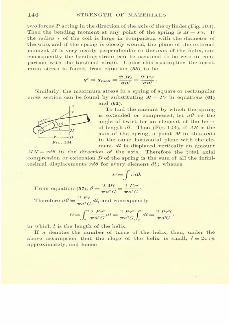
7/30/2019 Textbook on Streng 00 Slo Crich
http://slidepdf.com/reader/full/textbook-on-streng-00-slo-crich 188/433
146 STRENGTH OF MATERIALS
two forces P acting in the direction of the axis of the cyUnder (Fig. 103).
Then the bending moment at any point of the spring is M= Pr, If
the radius r of the coil is large in comparison with the diameter of
the wire, and if the spring is closely wound, the plane of the external
moment M is very nearly perpendicular to the axis of the helix, and
consequently the bending strain can be assumed to be zero in com-
parison with the torsional strain. Under this assumption the maxi-
mum stress is found, from equation (55), to be
Tra 7TCT
Similarly, the maximum stress in a spring of square or rectangular
cross section can be found by substituting M= Pr in equations (61)
and(62).
To find the amount by which the spring
is extended or compressed, let d6 be the
angle of twist for an eleruent of the helix
of length dl. Then (Fig. 104), if AB is the
axis of the spring, a point M in this axis
in the same horizontal plane with the ele-
ment dl is displaced vertically an amount
MN rdO in the direction of the axis. Therefore the total axial
compression or extension D of the spring is the sum of all the infini-
tesimal displacements rdO for every element dl;whence
D= CrdO.
v ,. /Kn a 2 Ml 2PrlFrom equation (57), 6 = = -
9 PrTherefore dO = dl
}and consequently
TTCl G
2Pr2l
/l
2 Pr2
2 Pr2
Cl
2 Pr2
<
ITCH (JT TTCt' (JT Jr. TTCL (j~<J
D
in which / is the length of the helix.
If n denotes the number of turns of the helix, then, under the
above assumption that the slope of the helix is small, I = 27rrn
approximately, and hence
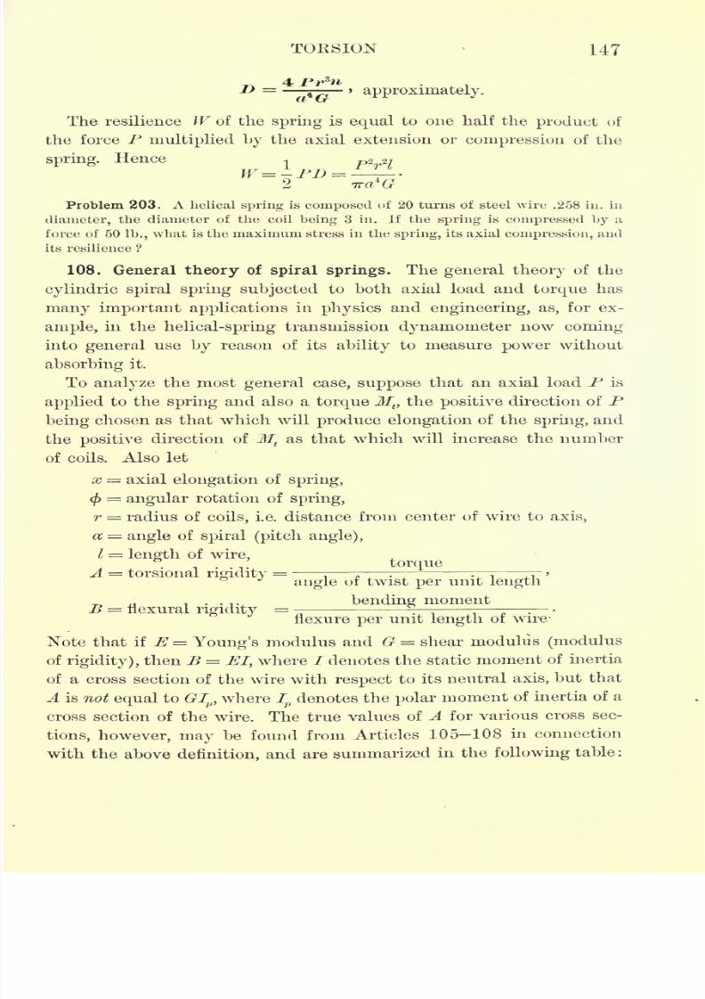
7/30/2019 Textbook on Streng 00 Slo Crich
http://slidepdf.com/reader/full/textbook-on-streng-00-slo-crich 189/433
TORSION 147
approximately.
The resilience W of the
spring
is
equal
to one half the
product
of
the force P multiplied by the axial extension or compression of the
spring.Hence -,
p2 27
Problem 203. A helical spring is composed of 20 turns of steel wire .258 in. in
diameter, the diameter of the coil being 3 in. If the spring is compressed by a
force of 50 lb., what is the maximum stress in the spring, its axial compression, and
its resilience ?
108. General theory of spiral springs. The general theory of the
cylindric spiral spring subjected to both axial load and torque has
many important applications in physics and engineering, as, for ex-
ample, in the helical-spring transmission dynamometer now coming
into general use by reason of its ability to measure power without
absorbing it.
Toanalyze
the mostgeneral
case,suppose
that an axial load P is
applied to the spring and also a torque Mt)the positive direction of P
being chosen as that which will produce elongation of the spring, and
the positive direction of Mtas that which will increase the number
of coils. Also let
x = axial elongation of spring,
cf)
=angular rotation of spring,
r = radius of coils, i.e. distance from center of wire to axis,
a ==angle of spiral (pitch angle),
/ = length of wire,torque
A = torsional rigidity=
B = flexural rigidity=
angle of twist per unit length
bending moment
flexure per unit length of wire-
Note that if E= Young's modulus and G = shear modulus (modulus
of rigidity), then B = El, where / denotes the static moment of inertia
of a cross section of the wire with respect to its neutral axis, but that
A is not equal to GIp ,where I
pdenotes the polar moment of inertia of a
cross section of the wire. The true values of A for various cross sec-
tions, however, may be found from Articles 105-108 in connection
with the above definition, and are summarized in the following table :
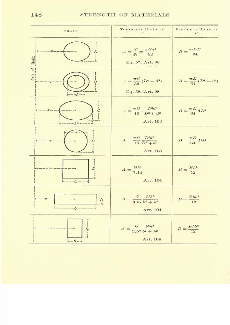
7/30/2019 Textbook on Streng 00 Slo Crich
http://slidepdf.com/reader/full/textbook-on-streng-00-slo-crich 190/433
148 STRENGTH OF MATERIALS
SHAIM:
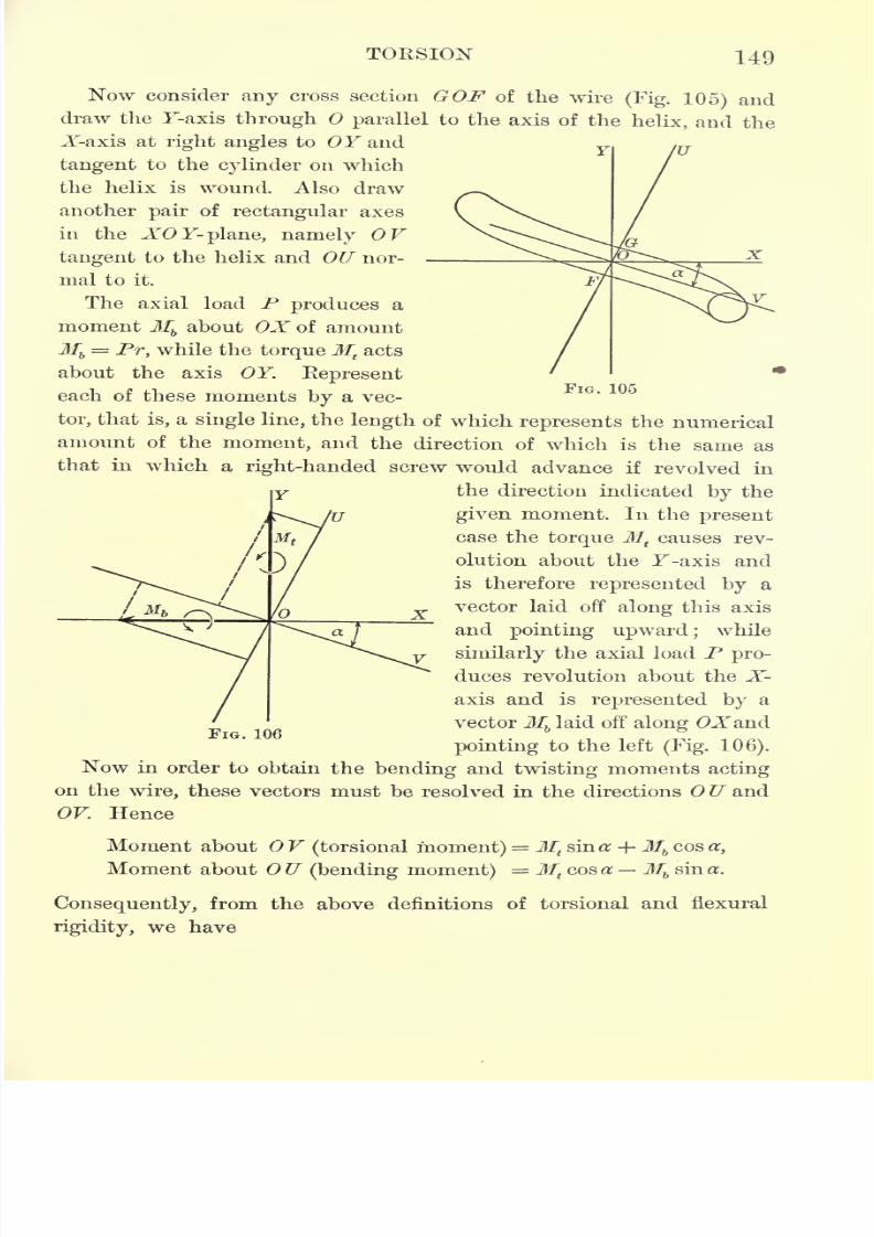
7/30/2019 Textbook on Streng 00 Slo Crich
http://slidepdf.com/reader/full/textbook-on-streng-00-slo-crich 191/433
TORSION 149
Now consider any cross section GOF of the wire(Fig. 105) and
draw the F-axis through parallel to the axis of the helix, and the
X-axis at right angles to OF and
tangent to the cylinder on which
the helix is wound. Also draw
another pair of rectangular axes
in the XOY- plane, namely OF
tangent to the helix and OU nor- -
mal to it.
The axial load P produces a
moment Mbabout OX of amount
Mb= Pr, while the torqueMt
acts
about the axis OF. Represent
each of these moments by a vec-
tor, that is, a single line, the length of which represents the numerical
amount of the moment, and the direction of which is the same as
that in which a right-handed screw would advance if revolved in
the direction indicated by the
u X
given moment. In the present
case the torque Mtcauses rev-
olution about the F-axis and
is therefore represented by a
vector laid off along this axis
and pointing upward; while
similarly the axial load P pro-
duces revolution about the X-
axis and is represented by a
vectorMblaid off along OXand
pointing to the left (Fig. 106).
Now in order to obtain the bending and twisting moments acting
on the wire, these vectors must be resolved in the directions U and
OF. Hence
Moment about V(torsional moment) =Mt
sin a; -+-Mbcos a,
Moment about U (bending moment) =Mtcos a M
bsin a.
Consequently, from the above definitions of torsional and flexural
rigidity, we have
FIG. 106
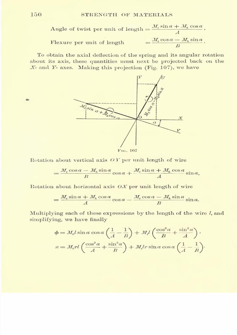
7/30/2019 Textbook on Streng 00 Slo Crich
http://slidepdf.com/reader/full/textbook-on-streng-00-slo-crich 192/433
150 STRENGTH OF MATERIALS
ATI...... Jf, sin a + Mhcos a
Angle of twist per unit of length= -
Flexure per unit of length
A
Mtcos a M
hsin a
To obtain the axial deflection of the spring and its angular rotation
about its axis, these quantities must next be projected back on the
X- and Y- axes. Making this projection (Fig. 107), we have
FIG. 107
Rotation about vertical axis Y per unit length of wire
Mf cos a Mh sin a Mtsin a -\-Mh cos a .
=-
cosoH sin a,-t> A
Rotation about horizontal axis OX per unit length of wire
M sin a +M cos acos a
M cos a M sin a .
Bsin a.
Multiplying each of these expressions by the length of the wire /, and
simplifying, we have finally
x = Mhrl
cos a sin a
jj A
1
7/30/2019 Textbook on Streng 00 Slo Crich
http://slidepdf.com/reader/full/textbook-on-streng-00-slo-crich 193/433
TOKSION 151
Special Case I. Spirals very flat.
In case the spirals are very flat, a may be as sumed to 1 e zero, and
the above expressions then reduce to
MJ, _
B
Special Case II. Ifotatioii of ends prevented, i.e.(/>= 0.
In this case first find Mtin terms of M
bfrom the equation < =
;
then substitute this value of Mtin the x equation and find x in terms
of Jf6.
Problem 204. Assume = and a = 45. Find x.
Solution. Substituting these numerical values of and a in the expression
/I 1\ /cos2 a sin2
= Mb l sin a cos al - -J+ Mt
l(
and solving the resulting equation for Mt ,we have
Substituting this value of Mtin the equation
,/cos2<* sin2
-\ /I 1\= Mbrl / --1
--J+ Mt
lr sin a cos a /- -
j,
2
x
we have finally
A +
Special Case III. Axial elongation prevented, i.e. x = 0.
This case applies to the helical-spring transmission dynamometer
mentioned above. In this case first find Mbin terms of M
tfrom the
equation x = 0, and then substitute this value of Mbin the
<f> equation
and find < in terms of Mt.
Problem 205. A helical-spring transmission dynamometer is made of 15f turns
of -in. steel wire, the mean diameter of the coil being 1^ in., and there being 2 turns
of wire per inch. Calculate the torque required to produce an angular deflection
of 25.
Solution. From the table the constants A and B for a circular cross section are
A = and B = Inserting these values in the equation x = 0, and assum-
ing the relation between the elastic moduli to be G = f E, the result is
sin a cos aA .
,
5 cos2 a + 4 snr a
7/30/2019 Textbook on Streng 00 Slo Crich
http://slidepdf.com/reader/full/textbook-on-streng-00-slo-crich 194/433
152 STRENGTH OF MATERIALS
From the given dimensions it is found that a = 7 15.4', and consequently
Mb= .02513Mt .
Inserting this value in the<f> equation and also
making
d = .25,=
,I =
62.35,and E = 30,000,000, the result of solving for Mt is
Mt= 40.06 in. Ib.
EXERCISES ON CHAPTER VI
Problem 206. Find the diameter of a structural-steel engine shaft to transmit
900 H.P. at 75 R.P.M. with a factor of safety of 10.
Problem 207. Find the factor of safety for a wrought-iron shaft 5 in. in
diameter which is transmitting 60 H.P. at 125 K.P.M.
Problem 208. A structural-steel shaft is 60ft. long and is required to transmit
500 H.P. with a factor of safety of 8 and to be of sufficient stiffness so that the
angle of torsion shall not exceed .5 per foot of length. Find its diameter.
Problem 209. Under the same conditions as in Problem 208 find the size of
a hollow shaft if the external diameter is twice the internal.
Problem 210. A hollow wrought-iron shaft 9 in. in external diameter and
2 in. thick is required to transmit 600 H.P. with a factor of safety of 10. At whatspeed should it be run ?
Problem 211. A horizontal steel shaft 4 in. in diameter and 10 ft. long be-
tween centers of bearings carries a pulley weighing 300 Ib. and 14 in. in diameter.
The belt on the pulley has a tension of 50 Ib. on the slack side and 175 Ib. on
the driving side. Find the maximum combined stress in the shaft.
Problem 212. An overhung steel crank carries a maximum thrust on the crank
pin of 2 tons. Length of crank 9 in.;distance from center of pin to center of
bearing 5 in. Determine the size of crank and shaft for a factor of safety of 5.
Problem213.
A propellershaft 9 in. in
diameter transmits 1000 H.P. at 90R.P.M. If the thrust on the screw is 12 tons, determine the maximum stress in
the shaft.
Problem 214. A round steel bar 2 in. in diameter, supported at points 4 ft.
apart, deflects .029 in. under a central load of 300 Ib. and twists 1.62 in a length
of 2 ft. under a twisting moment of 1500 ft. Ib. Find E, (?, and Poisson's ratio
for the material (see Article 35).
Problem 215. If P and Q denote the unit stresses at the elastic limits of a
pmaterial in tension and shear respectively, show that when <1 the material will
P Qfail in tension, whereas when > 1 it will fail in shear, when subjected to com-
bined bending and torsion, irrespective of the relative values of the bending and
twisting moments.
Solution. Combining Rankine's and Guest's formulas, we have
16Mh
P V = '
7/30/2019 Textbook on Streng 00 Slo Crich
http://slidepdf.com/reader/full/textbook-on-streng-00-slo-crich 195/433
TORSION 153
Consequently, if the bending moment is zero, p' = q' or =1, whereas if it is
<l'tf
not zero, p' > q'. Similarly, if the twisting moment is zero, = 2.
9'
Nowlet
Ft
and
Fs
denote the factors ofsafety
in tension and shearrespectively.
ThenP
Ft = = Ptf
Fs Q Qp>'
Q'
Since p' ==<?', the fraction = 1. Consequently, if <1 also, then <l;i.e.p' Q Fs
Ft < Fs and the material is weaker in tension than in shear. The second part of the
theorem is proved in a similar manner.For a complete discussion of this question see article by A. L. Jenkins, En-
gineering News (London, November 12, 1909), pp. 637-639.
Problem 216. A steel -shaft subjected to combined bending and torsion has
an elastic limit in tension of 64,600 lb./in.2 and an elastic limit in shear of
29,170 lb./in.2 Show that Guest's formula applies to this material rather than
Rankine's.
Problem 217. A shaft subjected to combined bending and twisting is made of
steel for which the elastic limit in tension is 28,800 lb./in.2 and the elastic limit in
shearis
16,000 lb./in.
2
Showthat if the
bendingmoment is one half the
twisting
moment, the shaft will be weakest in shear, whereas if the bending moment is twice
the twisting moment, it will be weakest in tension.
Problem 218. A closely coiled helical spring is made of5-111.
round steel wire
and has 15 coils of mean diameter 3 in. Find its deflection under an axial
.load of 20 lb., and the stiffness of the spring in pounds per foot of deflection.
Problem 219. A helical-spring transmission dynamometer is made of 20 turns
of J-in. steel wire;mean diameter of coil 2| in. with 2 turns per inch. Find its
axial twist in degrees when transmitting 6 H.P. at 75 R.P.M.
Problem 220. Aclosely
coiled helical
springis made of
f-in.
steel wire with
coils of 3 in. mean diameter. Find the length of wire required in order that the
spring shall deflect f-in. per pound of load.
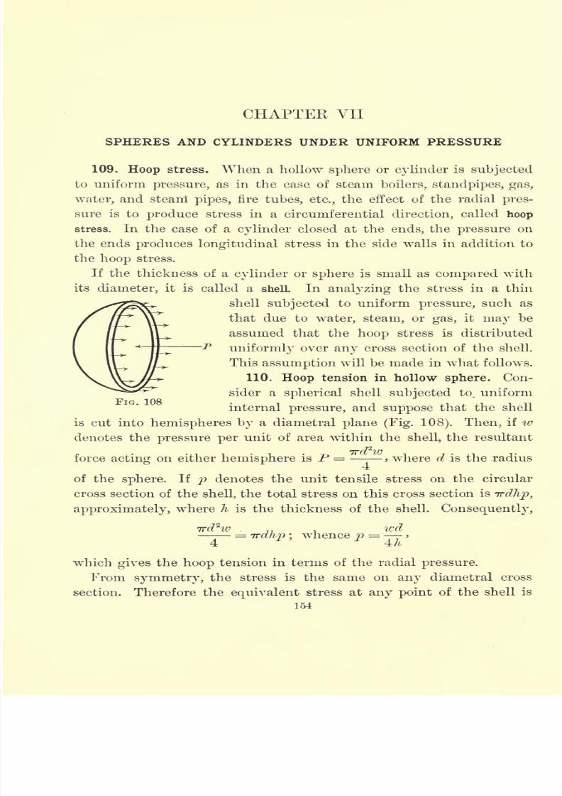
7/30/2019 Textbook on Streng 00 Slo Crich
http://slidepdf.com/reader/full/textbook-on-streng-00-slo-crich 196/433
CHAPTER VII
SPHERES AND CYLINDERS UNDER UNIFORM PRESSURE
109. Hoop stress. When a hollow sphere or cylinder is subjected
to uniform pressure, as in the case of steam boilers, standpipes, gas,
water, and steani pipes, fire tubes, etc., the effect of the radial pres-
sure is to produce stress in a circumferential direction, called hoop
stress. In the case of a cylinder closed at the ends, the pressure on
the ends produces longitudinal stress in the side walls in addition to
the hoop stress.
If the thickness of a cylinder or sphere is small as compared with
its diameter, it is called a shell In analyzing the stress in a thin
shell subjected to uniform pressure, such as
that due to water, steam, or gas, it may be
assumed that the hoop stress is distributed
uniformly over any cross section of the shell.
This assumption will be made in what follows.
110. Hoop tension in hollow sphere. Con-
sider a spherical shell subjected to^ uniform
internal pressure, and suppose that the shell
is cut into hemispheres by a diametral plane (Fig. 108). Then, if w
denotes the pressure per unit of area within the shell, the resultant
force acting on either hemisphere is P = > where d is the radius
of the sphere. If p denotes the unit tensile stress on the circular
cross section of the shell, the total stress on this cross section is Trdhp,
approximately, where h is the thickness of the shell. Consequently,
ird^w wd=
irdlip ;whence p = -
>
4 4h
which gives the hoop tension in terms of the radial pressure.
From symmetry, the stress is the same on any diametral cross
section. Therefore the equivalent stress at any point of the shell is
154
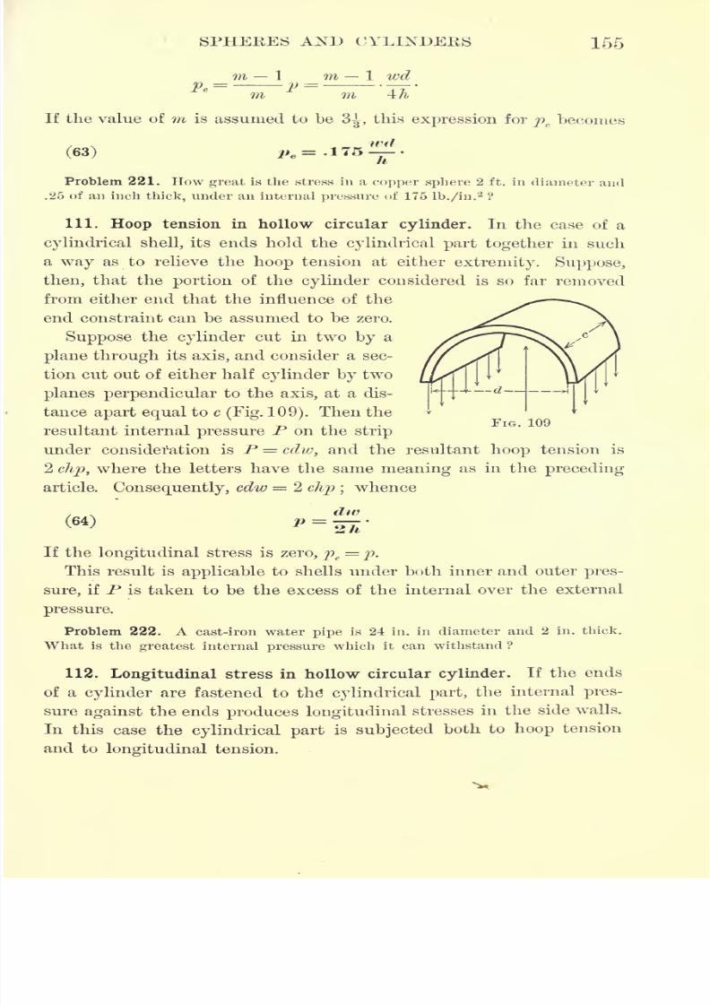
7/30/2019 Textbook on Streng 00 Slo Crich
http://slidepdf.com/reader/full/textbook-on-streng-00-slo-crich 197/433
SPHERES AND CYLINDERS 155
m 1
10 =- vl wd
4/i,m
If the value of m is assumed to be3^,
this expression for pebecomes
Problem 221. How great is the stress in a copper sphere 2 ft. in diameter and
.25 of an inch thick, under an internal pressure of 175 lb./in.2?
111. Hoop tension in hollow circular cylinder. In the case of a
cylindrical shell, its ends hold the cylindrical part together in such
a way as to relieve the hoop tension at either extremity. Suppose,
then, that the portion of the cylinder considered is so far removed
from either end that the influence of the
end constraint can be assumed to be zero.
Suppose the cylinder cut in two by a
plane through its axis, and consider a sec-
tion cut out of either half cylinder by two
planes perpendicular to the axis, at a dis-
tance apart equal to c(Fig. 109). Then the
resultant internal pressure P on the strip
under consideration is P = cdw, and the resultant hoop tension is
2 clip, where the letters have the same meaning as in the preceding
article. Consequently, cdw = 2 clip ;whence
div
FIG. 109
(64) p =
If the longitudinal stress is zero, pe=
p.
This result is applicable to shells under both inner and outer pres-
sure, if P is taken to be the excess of the internal over the external
pressure.
Problem 222. A cast-iron water pipe is 24 in. in diameter and 2 in. thick.
What is the greatest internal pressure which it can withstand ?
112. Longitudinal stress in hollow circular cylinder. If the ends
of a cylinder are fastened to the* cylindrical part, the internal pres-
sure against the ends produces longitudinal stresses in the side walls.
In this case the cylindrical part is subjected both to hoop tension
and to longitudinal tension.
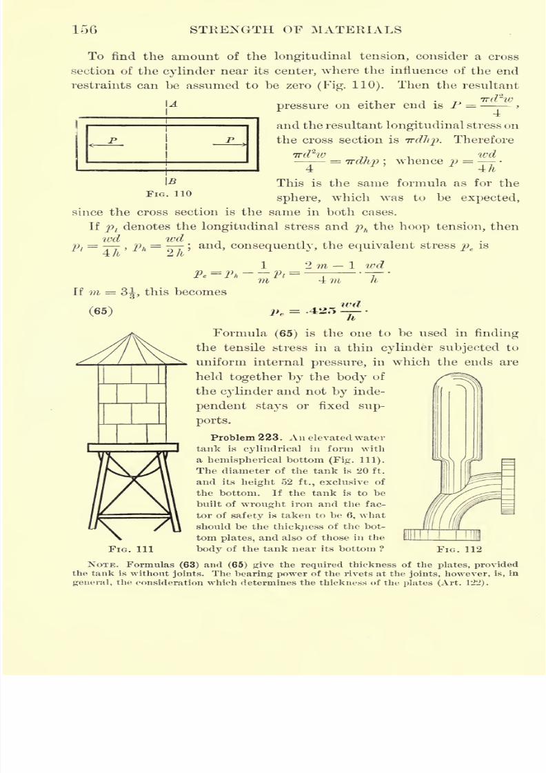
7/30/2019 Textbook on Streng 00 Slo Crich
http://slidepdf.com/reader/full/textbook-on-streng-00-slo-crich 198/433
156 STRENGTH OF MATERIALS
To find the amount of the longitudinal tension, consider a cross
section of the cylinder near its center, where the influence of the end
restraints can be assumed to be zero (Fig. 110). Then the resultant
\A ird'' W
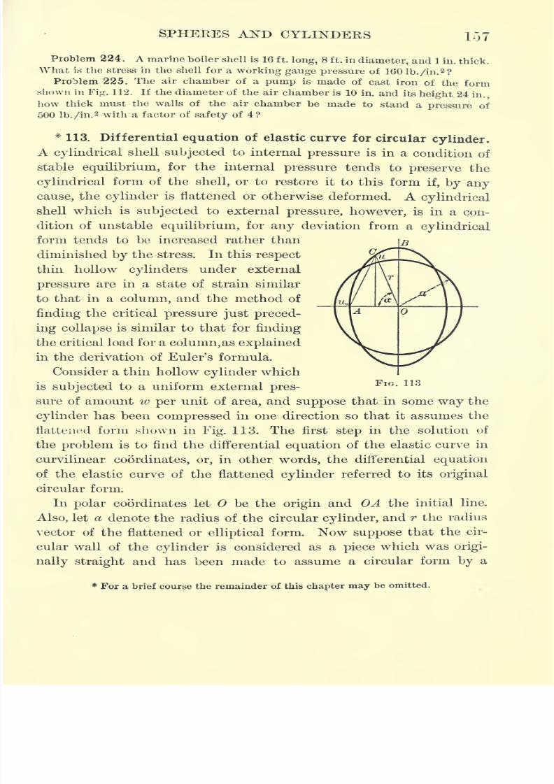
7/30/2019 Textbook on Streng 00 Slo Crich
http://slidepdf.com/reader/full/textbook-on-streng-00-slo-crich 199/433
SPHERES AND CYLINDERS 157
B
Problem 224 . A marine boiler shell is 16 ft. long, 8 ft. in diameter, and 1 in. thick.
What is the stress in the shell for a working gauge pressure of 160 lb./in.2 ?
Problem 225. The air chamber of a pump is made of cast iron of the formshown in Fig. 112. If the diameter of the air chamber is 10 in. and its height 24
in.,
how thick must the walls of the air chamber be made to stand a pressure of
500 lb./in.2 with a factor of safety of 4?
*113. Differential equation of elastic curve for circular cylinder.
A cyliudrical shell subjected to internal pressure is in a condition of
stable equilibrium, for the internal pressure tends to preserve the
cylindrical form of the shell, or to restore it to this form if, by any
cause, the cylinder is flattened or otherwise deformed. A cylindrical
shell which is subjected to external pressure, however, is in a con-
dition of unstable equilibrium, for any deviation from a cylindrical
form tends to be increased rather than
diminished by the stress. In this respect
thin hollow cylinders under external
pressure are in a state of strain similar
to that in a column, and the method of
finding the critical pressure just preced-
ing collapse is similar to that for finding
the critical load for a column,as explained
in the derivation of Euler's formula.
Consider a thin hollow cylinder which
is subjected to a uniform external pres-
sure of amount w per unit of area, and suppose that in some way the
cylinder has been compressed in one direction so that it assumes the
flattened form shown in Fig. 113. The first step in the solution of
the problem is to find the differential equation of the elastic curve in
curvilinear coordinates, or, in other words, the differential equation
of the elastic curve of the flattened cylinder referred to its original
circular form.
In polar coordinates let be the origin and OA the initial line.
Also, let a denote the radius of the circular cylinder, and r the radius
vector of the flattened or elliptical form. Now suppose that the cir-
cular wall of the cylinder is considered as a piece which was origi-
nally straight and has been made to assume a circular form by a
FIG. 113
* For a brief course the remainder of this chapter may be omitted.

7/30/2019 Textbook on Streng 00 Slo Crich
http://slidepdf.com/reader/full/textbook-on-streng-00-slo-crich 200/433
158 STRENGTH OF MATERIALS
bending moment M'. Then, if p denotes the radius of curvature, from
Article 66, -
,
Again, suppose that this circular cylinder is made to assume the
flattened form as the result of an additional bending moment M, and
let pf
denote the corresponding radius of curvature. Then
1 _ M' + MJ'~ El
Consequently,
(ee)J~J = Jr
From the differential calculus,
2-ii
dr\*
)da da2
drIf the deformation is small,
-- is infinitesimal, and r differs mfinitesi-da
mally from a. Therefore, neglecting infinitesimals of an order higher
than the second, the expression forp' becomes
P'd2r d
2r
a2 - a a--
da2 da2
and, consequently, -, -, 1/72.
p' a a?
Since p = ,- = -, and therefore
p a
(67)
^~~p= ~
Comparing equations (66) and (67)
(68> V^ =d^ / S-*4 sJ STS&
*The sign is used because the calculus expression for p' contains a square root in
the numerator.
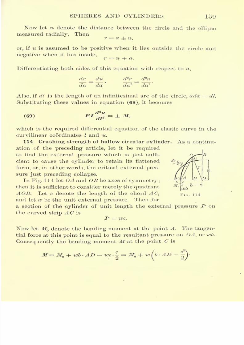
7/30/2019 Textbook on Streng 00 Slo Crich
http://slidepdf.com/reader/full/textbook-on-streng-00-slo-crich 201/433
SPHERES AND CYLINDERS 159
Now let u denote the distanca between the circle and the ellipse
measured radially. Thenr = a u,
or, if u is assumed to be positive when it lies outside the circle and
negative when it lies inside,r = u + a.
Differentiating both sides of this equation with respect to a,
dr du
da da
d2r
Also, if dl is the length of an infinitesimal arc of the circle, ada = dl.
Substituting these values in equation (68), it becomes
(69)
which is the required differential equation of the elastic curve in the
curvilinear coordinates I and u.
114. Crushing strength of hollow circular cylinder. 'As a continu-
ation of the preceding article, let it be required
to find the external pressure which is just suffi-
cient to cause the cylinder to retain its flattened
form, or, in other words, the critical external pres-
sure just preceding collapse.
In Fig. 114 let OA and OB be axes of symmetry;
then it is sufficient to consider merely the quadrant
A OB. Let c denote the length of the chord AC,
and let w be the unit external pressure. Then for
a section of the cylinder of unit length the external pressure P on
the curved strip AC is
P = we.
Now let M denote the bending moment at the point A. The tangen-
tial force at this point is equal to the resultant pressure on OA, or wb.
Consequently the bending moment M at the point C is
114
7/30/2019 Textbook on Streng 00 Slo Crich
http://slidepdf.com/reader/full/textbook-on-streng-00-slo-crich 202/433
160 STRENGTH OF MATERIALS
In the triangle OAC,
~OC* = 'AC1
+ AC? -2AO- AD, or
r2 = c
2
+62 - 2 b A
D,from which 2 2 2
Since r = u + a and a = b UQ)
*
in
M= MQ + - (a2
+ 2 aw + ^ - a2
- 2
Since w and UQare both infinitesimal, w
c + u(or the difference between
the absolute values of u and u)is negligible in comparison with 2 .
Therefore M= M -wa(u
- u),
and, consequently, the differential equation of the elastic curve becomes
The general integral of this differential equation is found to be
(70) M = Wo +
^
+ ClSi
in which Cland (7
2are the undetermined constants of integration.!
This may be verified by substituting the integral in the above differ-
ential equation.
To determine Cland C
2it is only necessary to make use of the
terminal conditions at A and B. At the point A yI 0,
=0, and
CLL
u = u .
Substitutingthese values in
equation (70)
and its first deriv-
ative, it is found that
a = and 0,,=-^-wa
*Throughout this discussion it should be borne in mind that u is a negative quantity.
t See Johnson, Treatise on Ordinary and Partial Differential Equations, 3d ed.,
pp. 85-86.
7/30/2019 Textbook on Streng 00 Slo Crich
http://slidepdf.com/reader/full/textbook-on-streng-00-slo-crich 203/433
SPHERES AND CYLINDERS
Hence the integral becomes
u =^ + u -^cos l^lwa wa ^llI
or
At the upper end of the quadrant B the conditions are I = and
= 0. Substituting these values in the first differential coefficientat
obtained from equation (71),
namely,
I~H
we have
du M Iwa . Iwa
whence
IwaEI 2
= "
where X is an arbitrary integer. Choosing the smallest value of X,
namely 1, this condition becomes
wa a=
whence
If the thickness of the tube is denoted by h, then, for a section of
h8
unit length, /= > and formula (72) becomes12
(73)
Formula (73) gives the critical pressure just preceding collapse ;that
is to say, it gives the maximum external pressure w per unit of area
which a cylindrical tube of thickness h can stand without crushing.
Problem 226. What is the maximum external pressure which a cast-iron pipe
18 in. in diameter and in. thick can stand without crushing ?
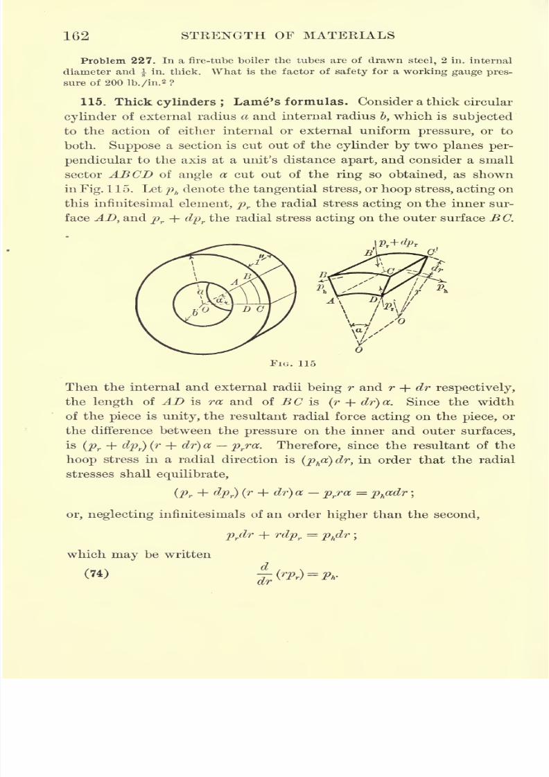
7/30/2019 Textbook on Streng 00 Slo Crich
http://slidepdf.com/reader/full/textbook-on-streng-00-slo-crich 204/433
162 STEENGTH OF MATERIALS
Problem 227. In a fire-tube boiler the tubes are of drawn steel, 2 in. internal
diameter and | in. thick. What is the factor of safety for a working gauge pres-
sure of 200 lb./in.2 ?
115. Thick cylinders ; Lame's formulas. Consider a thick circular
cylinder of external radius a and internal radius &, which is subjected
to the action of either internal or external uniform pressure, or to
both. Suppose a section is cut out of the cylinder by two planes per-
pendicular to the axis at a unit's distance apart, and consider a small
sector ABCD of angle a cut out of the ring so obtained, as shown
in Fig. 115. Letphdenote the tangential stress, or hoop stress, acting on
tin's infinitesimal element, pr the radial stress acting on the inner sur-
face AD, and pr + dprthe radial stress acting on the outer surface BC.
FIG. 115
Then the internal and external radii being r and r + dr respectively,
the length of AD is ra and of BC is (r -f dr)a. Since the widthof the piece is unity, the resultant radial force acting on the piece, or
the difference between the pressure on the inner and outer surfaces,
is (pr + dpr) (r -f dr) a prra. Therefore, since the resultant of the
hoop stress in a radial direction is (pha) dr, in order that the radial
stresses shall equilibrate,
(pr + dpr) (r + dr) a prra = ph
adr;
or, neglecting infinitesimals of an order higher than the second,
prdr + rdpr
= phdr
;
which may be written
(74)-
7/30/2019 Textbook on Streng 00 Slo Crich
http://slidepdf.com/reader/full/textbook-on-streng-00-slo-crich 205/433
SPHERES AND CYLINDERS 163
If the ends of the cylinder are free from restraint, or if the cylinder
is subjected to a uniform longitudinal stress, the longitudinal defor-
mation must be constant throughout the cylinder. The longitudinal
deformation, however, is due to the lateral action of prand ph ,
and is
7) 1) 1of amount -^-
-f-~-
> or -(pr + ph),
in which m denotes Poisson'smE mE mE
constant. Therefore, if this expression is constant, pr + phmust
be constant, and hence _ -,
Pr ~r Ph K>
where k is a constant. Consequently, ph= k pr ,
and substituting
this valueof
phin
equation (74)and
multiplying by r,it becomes
krdr = 2 rprdr -\- r
1
dpr ,
which may be written^
dr
Integrating, ^
in which Clis
the constantof
integration ;
whence
Also, since ph= k pr ,
Now suppose that the cylinder is subjected to a uniform internal
pressure of amount wi per unit of area, and also to a uniform external
pressure of amount we per unit of area. Then pr
wewhen r a,
and pr= w
iwhen r = 1. Substituting these values in equation (75),
i- r1i- r^
/v V/itu \j *-
whence 27 2 / _ \ o
Therefore, substituting these values of <7Xand k in equations (75) and
(76), they become
_ weaz
Wjb2 azb2
(we
(77)
.a'Q'(we
-I /^.2 i,2\
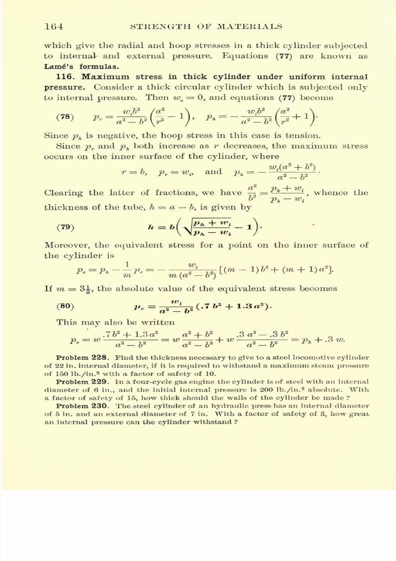
7/30/2019 Textbook on Streng 00 Slo Crich
http://slidepdf.com/reader/full/textbook-on-streng-00-slo-crich 206/433
164 STRENGTH OF MATERIALS
which give the radial and hoop stresses in a thick cylinder subjected
to internal and external pressure. Equations (77)are known as
Lamp's formulas.
116. Maximum stress in thick cylinder under uniform internal
pressure. Consider a thick circular cylinder which is subjected only
to internal pressure. Then we=
0, and equations (77)become
w a? \ w /2
(78)
Since phis negative, the hoop stress in this case is tension.
Since pr and ph both increase as r decreases, the maximum stress
occurs on the inner surface of the cylinder, where
w-(a -\- b )
T = 0. f) = w., and t), =JJ T 1* M ft 2 Z.2
Clearing the latter of fractions, we have = l-
,whence the
thickness of the tube, h = a &, is given by
(79) h = b\
Moreover, the equivalent stress for a point on the inner surface of
the cylinder is
If m = 3J,
the absolute value of theequivalent
stress becomes
This may also be written
Problem 228. Find the thickness necessary to give to a steel locomotive cylinder
of 22 in. internal diameter, if it is required to withstand a maximum steam pressure
of 150 lb./in.2 with a factor of safety of 10.
Problem 229. In a four-cycle gas engine the cylinder is of steel with an internal
diameter of 6 in., and the initial internal pressure is 200 lb./in.2 absolute. With
a factor of safety of 15, how thick should the walls of the cylinder be made ?
Problem 230. The steel cylinder of an hydraulic press has an internal diameter
of 5 in. and an external diameter of 7 in. With a factor of safety of 3, how great
an internal pressure can the cylinder withstand ?
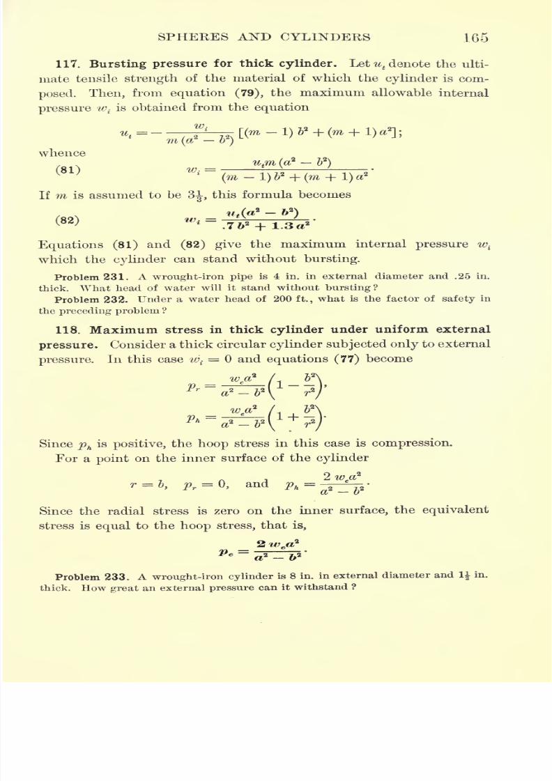
7/30/2019 Textbook on Streng 00 Slo Crich
http://slidepdf.com/reader/full/textbook-on-streng-00-slo-crich 207/433
SPHEEES AND CYLINDERS 165
117. Bursting pressure for thick cylinder. Let ^denote the ulti-
mate tensile strength of the material of which the cylinder is com-
posed. Then, from equation (79), the maximum allowable internal
pressure wiis obtained from the equation
whence
If m is assumed to be3J,
this formula becomes
ut(a*- ft
2
)
Equations (81) and (82) give the maximum internal pressure w{
which the cylinder can stand without bursting.
Problem 231. A wrought-iron pipe is 4 in. in external diameter and .25 in.
thick. What head of water will it stand without bursting?
Problem 232. Under a water head of 200 ft., what is the factor of safety in
the preceding problem ?
118. Maximum stress in thick cylinder under uniform external
pressure. Consider a thick circular cylinder subjected only to external
pressure. In this case wi
= and equations (77) become
Since phis positive, the hoop stress in this case is compression.
For a point on the inner surface of the cylinder
2 wea2
r = b, pr=
Q, and Ph= ^p'
Since the radial stress is zero on the inner surface, the equivalent
stress is equal to the hoop stress, that is,
Problem 233. A wrought-iron cylinder is 8 in. in external diameter and \\ in.
thick. How great an external pressure can it withstand ?
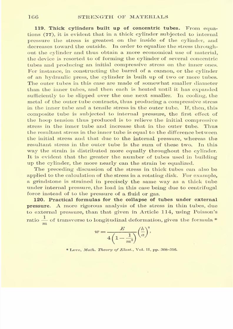
7/30/2019 Textbook on Streng 00 Slo Crich
http://slidepdf.com/reader/full/textbook-on-streng-00-slo-crich 208/433
166 STRENGTH OF MATERIALS
119. Thick cylinders built up of concentric tubes. From equa-
tions (77), it is evident that in a thick cylinder subjected to internal
pressurethe stress is
greateston the inside of the
cylinder,and
decreases toward the outside. In order to equalize the stress through-
out the cylinder and thus obtain a more economical use of material,
the device is resorted to of forming the cylinder of several concentric
tubes and producing an initial compressive stress on the inner ones.
For instance, in constructing the barrel of a cannon, or the cylinder
of an hydraulic press, the cylinder is built up of two or more tubes.
The outer tubes in this case are made of somewhat smaller diameter
than the inner tubes, and then each is heated until it has expanded
sufficiently to be slipped over the one next smaller. In cooling, the
metal of the outer tube contracts, thus producing a compressive stress
in the inner tube and a tensile stress in the outer tube. If, then, this
composite tube is subjected to internal pressure, the first effect of
the hoop tension thus produced is to relieve the initial compressive
stress in the inner tube and increase that in the outer tube. Thus
the resultant stress in the inner tube is equal to the difference between
the initial stress and that due to the internal pressure, whereas the
resultant stress in the outer tube is the sum of these two. In this
way the strain is distributed more equally throughout the cylinder.
It is evident that the greater the number of tubes used in building
up the cylinder, the more nearly can the strain be equalized.
Thepreceding
discussion of the stress in thick tubes can also be
applied to the calculation of the stress in a rotating disk. For example,
a grindstone is strained in precisely the same way as a thick tube
under internal pressure, the load in this case being due to centrifugal
force instead of to the pressure of a fluid or gas.
120. Practical formulas for the collapse of tubes under external
pressure. A more rigorous analysis of the stress in thin tubes, due
to externalpressure,
than that
givenin Article 114,
using
Poisson's
ratio of transverse to longitudinal deformation, gives the formula *
mE
w
4 l--v \
*Love, Math. Theory ofElast., Vol. II, pp. 308-316.
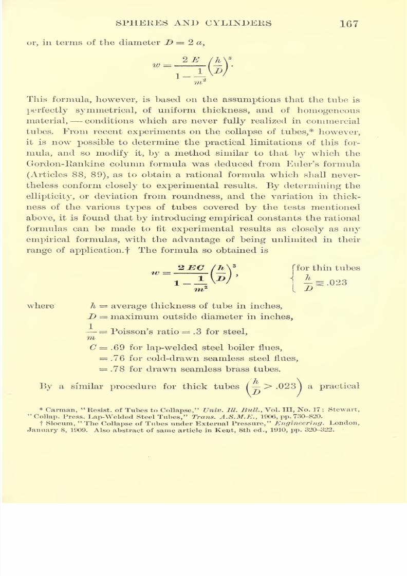
7/30/2019 Textbook on Streng 00 Slo Crich
http://slidepdf.com/reader/full/textbook-on-streng-00-slo-crich 209/433
SPHEKES AND CYLINDERS 167
or, m terms of the diameter D = 2 a,
This formula, however, is based on the assumptions that the tube is
perfectly symmetrical, of uniform thickness, and of homogeneous
material, conditions which are never fully realized in commercial
tubes. From recent experiments 011 the collapse of tubes,* however,
it is now possible to determine the practical limitations of this for-
mula, and so modify it, by a method similar to that by which the
Gordon-Eankine column formula was deduced from Euler's formula
(Articles 88, 89), as to obtain a rational formula which shall never-
theless conform closely to experimental results. By determining the
ellipticity, or deviation from roundness, and the variation in thick-
ness of the various types of tubes covered by the tests mentioned
above, it is found that by introducing empirical constants the rational
formulas can be made to fit experimental results as closely as any
empirical formulas, with the advantage of being unlimited in their
range of application.! The formula so obtained is
ffor thin tubes
t 5
where h = average thickness of tube in inches,
D = maximum outside diameter in inches,
= Poisson's ratio = .3 for steel,mC = .69 for lap-welded steel boiler flues,
= .76 for cold-drawn seamless steel flues,
= .78 for drawn seamless brass tubes.
By a similar procedure for thick tubes /
>.023)a practical
*Carman,
"Resist, of Tubes to Collapse," Univ. HI. Bull., Vol. Ill, No. 17
; Stewart,
"Collap. Press. Lap-Welded Steel Tubes," Trans. A.S.M.E., 1906, pp. 730-820.
t Slocum,"The Collapse of Tubes under External Pressure," Engineering. London,
January 8, 1909. Also abstract of same article in Kent, 8th ed., 1910, pp. 320-322.
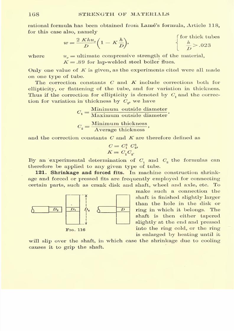
7/30/2019 Textbook on Streng 00 Slo Crich
http://slidepdf.com/reader/full/textbook-on-streng-00-slo-crich 210/433
168 STRENGTH OF MATERIALS
rational formula has been obtained from Lame's formula, Article 118,
for this case also, namely
IK)
w D
for thick tubes
where uc= ultimate compressive strength of the material,
K= .89 for lap-welded steel boiler flues.
Only one value of K is given, as the experiments cited were all made
on one type of tube.
The correction constants C and K include corrections both for
ellipticity,or flattening of the tube, and for variation in thickness.
Thus if the correction for ellipticityis denoted by C
land the correc-
tion for variation in thickness by <72
,we have
Minimum outside diameter
1
_
Maximum outside diameter
Minimum thickness
Average thickness
and the correction constants C and K are therefore denned as
By an "experimental determination of C1and C
2the formulas can
therefore be applied to any given type of tube.
121. Shrinkage and forced fits. In machine construction shrink-
age and forced or pressed fits are frequently employed for connecting
certain parts, such as crank disk and shaft, wheel and axle, etc. To
make such a connection the
shaft is finished slightly larger
than the hole in the disk or
ring in which it belongs. The
shaft is then either tapered
slightly at the end and pressed
into the ring cold, or the ring
is enlarged by heating until it
will slip over the shaft, in which case the shrinkage due to cooling
causes it to grip the shaft,
Di D
FlG
7/30/2019 Textbook on Streng 00 Slo Crich
http://slidepdf.com/reader/full/textbook-on-streng-00-slo-crich 211/433
SPHERES AND CYLINDERS 169
To analyze the stresses arising from shrinkage and forced fits, let
Dldenote the diameter of the hole in the ring or disk, and Z>
2the
diameter of the shaft (Fig. 116). When shrunk or forced together,
Dl must increase slightly and D2 decrease slightly, i.e. Dl and Z>2
must of necessity take the same value D. Consequently the circum-
ference of the hole changes from 7rDlto 7rZ>, and hence the unit
deformation sxof a fiber on the inner surface of the hole is
l
7TD, D
Similarlythe unit deformation s
2
of a fiber on the surface of the
Shaftis
AFrom Hooke's law, = E
ywe have therefore for the unit stress pl
s
on the inside of the disk
i = .1
=:^;E, D,
and for the unit stress p on the surface of the shaft
Adding these two equations to eliminate the unknown quantity
the result is
where K denotes the allowance, or difference in diameter of shaft and
hole. For a thick disk or heavy ring this allowance K may be deter-
mined from the nominal diameter D of the shaft by means of the
following empirical formulas.*
For shrinkage fits, K= \,
For pressed fits, K= ^>
For driven fits, K= ^ 2
* S. H. Moore, Tram. Am. Soc. Mech. Eng., Vol. XXIV.
7/30/2019 Textbook on Streng 00 Slo Crich
http://slidepdf.com/reader/full/textbook-on-streng-00-slo-crich 212/433
170 STRENGTH OF MATERIALS
For thin rings, however, the allowance given by these formulas will
be found to produce stresses in the ring entirely too large for safety.
In deciding on the allowance for any given class of work, the working
stresses in shaft and ring may first be assigned and the allowance
then determined from the formulas given below so that the actual
stresses shall not exceed these values.
From Lame's formulas the stresses pland p2 may be obtained in
terms of the unit pressure between the surfaces in contact. Thus
from formula (80) the equivalent stress on the inside of the hole is
A=A =-
(-7^ + 1.819,
where Z>3denotes the outside diameter of the ring, while, by substi-
tuting r = a and b = in the equations of Article 118, the stresses
on the outer surface of the shaft are found to be
Ph= W
> Pr=
>
and consequently -,
P2=Ph-Pr = -7w-
Eliminating w between these expressions forp^
and p ,we have
~.7
Now to simplify the solution, let the coefficient of p2be denoted by
H; that is,let
U == >rr / T\2
7~)2\
in which case
p l
= Hp2.
Eliminating plbetween this relation and the above expression for the
allowance K, we have finally
Pi = Hp z .
In applying these formulas the constant .If is first computed from the
given dimensions qf the parts. If the allowance K is given, the unit
7/30/2019 Textbook on Streng 00 Slo Crich
http://slidepdf.com/reader/full/textbook-on-streng-00-slo-crich 213/433
SPHERES AND CYLINDERS 171
stresses pland p2
in ring and shaft are then found from the above.
If K is to be determined, a safe value for the stress in thering, p ,
is
assigned, and p2calculated from the second equation. This value is
then substituted in the first equation and K calculated.
The following problem illustrates the application of the formulas.
Problem 234. A cast-iron gear, 8 in. external diameter, 3 in. wide, and If in.
internal diameter, is to be forced on a steel shaft. Find the stresses developed, the
pressure required to force the gear on the shaft, and the tangential thrust required
to'shear thefit, i.e. produce relative motion between gear and shaft.
Solution. From the formulaK 2 the allowance is found to be .004 in.,1000
makingthe diameter of the shaft D2 = 1.754 in. Also since
DI= 1.75
in.,
D3
= 8in.,
we have H - 2.0007. Hence assuming EI = 15,000,000 lb./in.2 and E2 = 30,000,000
lb./in.2
,we have
p l= 13,713 lb./in.
2, p2
= 27,436 lb./in.2
To find the pressure required to force the gear on the shaft it is first necessary
to calculate the pressure between the surfaces in contact. From the relation
p2= . 7 w this amounts to
u> = 39,194 lb./in.2
The coefficient of friction depends on the nature of the surfaces in contact. As-
suming it to be /t = .15 as an average value, and with a nominal area of contact
of TT x If x 3 = 16.485 in.2
,the total pressure P required is
P = 16.485 x 39,194 x .15 = 96,917 Ib. = 48.5 tons.
To find the torsional resistance of thefit,
we have, as above
Bearing area = 16.485 in.2
,Unit pressure = 39,194 lb./in.
2,
/x,=
.15, radius of shaft = .875 in.
Hence the torsional resistance is
Mt
= 16.485 x 39,194 x .15 x .875 = 85,000 in. Ib.
Consequently the tangential thrust on the teeth of the gear necessary to shear
the fit is
isoao _21,250 Ib. = 10.6 tons.
122. Riveted joints. In structural work such as plate girders,
trusses, etc., and also in steam boilers, standpipes, and similar con-
structions, the connections between the various members are madeby riveting the parts together. As the holes for the rivets weaken
the members so joined, the strength of the structure is determined
by the strength of the joint.
Failure of a riveted joint may occur in various ways,namely, by shear-
ing across the rivet, by crushing the rivet, by crushing the plate in

7/30/2019 Textbook on Streng 00 Slo Crich
http://slidepdf.com/reader/full/textbook-on-streng-00-slo-crich 214/433
172 STRENGTH OF MATERIALS
front of the rivet, by shearing the plate, i.e. pulling out the rivets, or
by tearing the plate along the line of rivet holes. Experience has
shown, however, that failure usually occurs either by shearing across
the rivet or by tearing the plate along the line of rivet holes.
The strength of any given type of riveted joint is expressed by
what is called its efficiency, denned as
strength of jointEfficiency of riveted joint =
strength of unriveted member
Thus if d (Fig. 117), denotes the diameter of a rivet and c the distance
between rivet holes, or pitch of the rivets as it is called, the efficiency
of the joint against tearing of the plate along the line of rivets is
c de =
To determine the efficiency of the joint against shearing across the
rivets, let q denote the ultimate shearing strength of the rivet and p
the ultimate tensile strength of the plate. Then for a single lap joint
(Fig. 117), if h denotes the thickness of the plate, the area corre-
J2
sponding to one rivet is hdtand the area in shear for each rivet is
;
consequently the efficiency of this type of joint against rivet shearing is
c =
For an economical design these two efficiencies should be equal. For
practical reasons, however, it is not generally possible to make these
exactly equal, and in this case the smaller of the two determines
the strength of the joint.
For a double-riveted lap joint the efficiency against tearing of the
plate is
c d
as above;but since in this case there are two rivets for each strip of
length c, the efficiency against rivet shear is
2chp
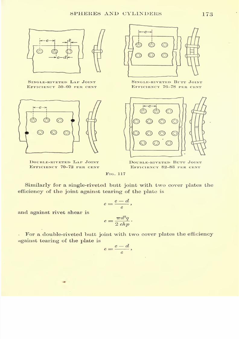
7/30/2019 Textbook on Streng 00 Slo Crich
http://slidepdf.com/reader/full/textbook-on-streng-00-slo-crich 215/433
SPHERES AND CYLINDERS 173
SINGLE-RIVETED LAP JOINT
EFFICIENCY 50-60PER CENT
SINGLE-RIVETED BUTT JOINT
EFFICIENCY76-78
PER CENT
DOUBLE-RIVETED LAP JOINT
EFFICIENCY 70-72 PER CENT
i*-c-*i
> (
y)
DOUBLE-RIVETED BUTT JOINT
EFFICIENCY 82-83 PER CENT
FIG. 117
Similarly for a single-riveted butt joint with two cover plates the
efficiency of the joint against tearing of the plate is
c d
and against rivet shear is
e = 2 chp
For a double-riveted butt joint with two cover plates the efficiency
against tearing of the plate is
c de =
7/30/2019 Textbook on Streng 00 Slo Crich
http://slidepdf.com/reader/full/textbook-on-streng-00-slo-crich 216/433
174 STRENGTH OF MATERIALS
and against rivet shear is
clip
The average efficiencies of various types of riveted joints as used in
steam boilers are given in Fig. 117.
In designing steam-boiler shells it is customary in this country to
determine first the thickness of shell plates by the following rule.
To find the thickness of shell plates, multiply the maximum steam
pressure to be carried (safe working pressure in lb./in.2
) by half the
diameter of the boiler in inches. This gives the hoop stress in the
shell per unit of length. Divide this result by the safe working stress
(working stress = ultimate strength, usually about 60,000 lb./in.2
,
divided by the factor of safety, say 4 or 5) and divide the quotient
by the average efficiency of the style of joint to be used, expressed as
a decimal. The result will be the thickness of the shell plates ex-
pressed in decimal fractions of an inch.
Having determined the thickness of shell plates by this method,
the diameter of the rivets is next found from the empirical formula
d = k^ft,
where k.= 1.5 for lap joints and Jc =1.3 for butt joints with two
cover plates.
The pitch of the rivets is next determined by equating the strength
of the plate along a section through the rivet holes to the strength
of the rivets in shear, and solving the resulting equation for c.
To illustrate the application of these rules, let it be required to
design a boiler shell 48 in. in diameter to carry a steam pressure of
125 lb./in.2with a double-riveted, double-strapped butt joint.
By the above rule for thickness of shell plates we have
125 X -V-h =-2 = .3, say -A m.e 0,000 x 82
5
The diameter of rivets is then
d =1.3 = .73, say fin.
To determine the pitch of the rivets, the strength of the plate for a
section of width c on a line through the rivet holes is
c- 5 X 60,000,
7/30/2019 Textbook on Streng 00 Slo Crich
http://slidepdf.com/reader/full/textbook-on-streng-00-slo-crich 217/433
SPHERES AND CYLINDERS 175
and the strength of the rivets in shear for a strip of this width is
4 x-q = 7r~x 40,000.4
J
ID
Equating these two results and solving for c, we have
(c -!)i
5
6x 60,000 = 71-^ x 40,000,
whence
c = 4. 5 in.
As a check on the correctness of our assumptions the efficiency of
the joint is found to be
-
c 4.5
For bridge and structural work the following^ enr^Fical rules are
representative of American practice.*
The pitch or distance from center to center of rivets should not
be less than 3 diameters of the rivet. In bridge work the pitch should
not exceed 6 inches, or 1 6 times the thickness of the thinnest outside
plates except in special cases hereafter noted. In the flanges of beams
and girders, where plates more than 12 inches wide are used, an extra
line of rivets with a pitch not greater than 9 inches should be driven
along each edge to draw the plates together.
At the ends of compression members the pitch should not exceed 4
diameters of the rivet for a length equal to twice the width or diameter
of the member.In the flanges of girders and chords carrying floors, the pitch should
not exceed 4 inches.
For plates in compression the pitch in the direction of the line of
stress should not exceed 16 times the thickness of the plate, and
the pitch in a direction at right angles to the line of stress should
not exceed 32 times the thickness, except for cover plates of top
chords and end posts in which the pitch should not exceed 40 times
their thickness.
The distance between the edge of any piece and the center of the
rivet hole should not be less than 1J inches for |-inchand |-inch
rivets except in bars less than 2J- inches wide;when practicable it
* Given by Cambria Steel Co.
7/30/2019 Textbook on Streng 00 Slo Crich
http://slidepdf.com/reader/full/textbook-on-streng-00-slo-crich 218/433
176 STRENGTH OF MATEEIALS
should, for all sizes, be at least 2 diameters of the rivet and should
not exceed 8 times the thickness of the plate.
EXERCISES ON CHAPTER VII
Problem 235. The end plates of a boiler shell are curved out to a radius of 5 ft.
If the plates are|
in. thick, find the tensile stress due to a steam pressure of
175 lb./in.2
Problem 236. If the thickness of the end plates in Problem 235 is changed to
\ in., the steam pressure being the same, to what radius should they be curved
in order that the tensile stress in them shall remain the same ?
Problem 237. In a double-riveted lap joint the plates are\ in. thick, rivets
| in. in diameter, and pitch 3 in. Calculate the efficiency of the joint.
Problem 238. A boiler shell is to be 4 ft. in diameter, with double-riveted lap
joints, and is to carry a steam pressure of 90 lb./in.2 with a factor of safety of 5.
Determine the thickness of shell plates, and diameter and pitch of rivets. Also
calculate the efficiency of the joint.
Problem 239. A cylindrical standpipe is 75 ft. high and 25 ft. inside diameter,
with double-riveted, two-strap butt joints. Determine the required thickness of
plates near the bottom for a factor of safety of 5, and also the diameter and pitch
of rivets.
Problem 240. The cylinder of an hydraulic press is 12 in. in diameter. Find
its thickness to stand a pressure of 1500 lb./in.2
,if it is made of cast iron and the
factor of safety is 10.
Problem 241. A high-pressure, cast-iron water main is 4 in. inside diameter and
carries a pressure of 800 lb./in.2 Find its thickness for a factor of safety of 15.
Problem 242. The water chamber of a fire engine has a spherical top 18 in.
in diameter, and carries a pressure of 250 lb./in.2 It is made of No. 7 B. and S.
gauge copper, which is reduced in manufacture to a thickness of about .1 in.
Determine the factor of safety.
Problem 243. A cast-iron ring 3 in. thick and 8 in. wide is forced on a steel
shaft 10 in. in diameter. Find the stresses in ring and shaft, the pressure required
to force the ring on the shaft, and the torsional resistance of the fit.
NOTE. Since the ring in this case is relatively thin, assume an allowance of about
half the amount given by Moore's formula. Then having given Dz = 10 in., Ds = 13 in.,
and computed the allowance K, we have also D\ = Di K, and inserting these values
in the formulas of Article 121, the required quantities may be found, as explained in
Problem 234.
Problem 244. The following data are taken from Stewart's experiments on the
collapse of thin tubes under external pressure, the tubes used for experiment
being lap-welded, steel boiler flues. Compute the collapsing pressure from the
rational formula for thin tubes, given in Article 120, for both the average thickness
and least thickness, and note that these two results lie on opposite sides of the
value obtained directly by experiment.
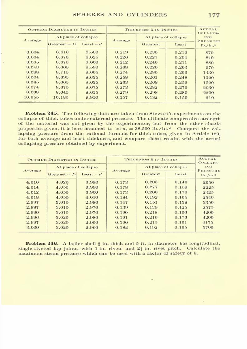
7/30/2019 Textbook on Streng 00 Slo Crich
http://slidepdf.com/reader/full/textbook-on-streng-00-slo-crich 219/433
SPHERES AND CYLINDERS 177
OUTSIDE DIAMETER IN INCHES

7/30/2019 Textbook on Streng 00 Slo Crich
http://slidepdf.com/reader/full/textbook-on-streng-00-slo-crich 220/433
178 STRENGTH OF MATERIALS
Problem 247. A cylindrical standpipe 80 ft. high and 20 ft. inside diameter is
made of ^-in. plates at the base with longitudinal, double-riveted, two-strap butt
joints, connected by 1-in. rivets with a pitch of 3 in. Compute the factor of safety
when the pipe is full of water.
Problem 248. In a single-riveted lap joint calculate the pitch of the rivets and
the distance from the center of the rivets to the edge of the plate under the assump-
tion that the diameter of the rivet is twice as great as the thickness of the plate.
Solution. Consider a strip of width equal to the rivet pitch, i.e. a strip contain-
ing one rivet. Let q denote the shearing strength of the rivet, and p the tensile of
the plate. Then if h denotes the thickness of the plate, in order that the shearing
strength of the rivet may be equal to the tensile strength of the plate along the line
of rivet holes, we must have
TTd2
q = (c-d)hp.
Since the rivet is usually of better material than the plate, we may assume that
the ultimate shearing strength of the rivet is equal to the ultimate tensile strength
of the plate, i.e. assume that p =q. Under this assumption the above relation
becomes
whence
c = 2.5d, approximately.
Similarly, in order that the joint may be equally secure against shearing off the
rivet and pulling it out of the plate, i.e. shearing the plate in front of the rivet,
the condition is
where a denotes the "margin," or distance from center of rivets to edge of plate,'
4
and q' denotes the ultimate shearing strength of the plate. Assuming that q' = -qd 5
and h = -,and solving the resulting expression for a, we have
7/30/2019 Textbook on Streng 00 Slo Crich
http://slidepdf.com/reader/full/textbook-on-streng-00-slo-crich 221/433
CHAPTER VIII
FLAT PLATES
123. Theory of flat plates. The analysis of stress in flat plates is,
at present, the most unsatisfactory part of the strength of materials.
Although flat plates are of frequent occurrence in engineering con-
structions, as, for example, in manhole covers, cylinder ends, floor
panels, etc., no general theory of such plates has as yet been given.
Each form of plate is treated by a special method, which, in most
cases, is based upon an arbitrary assumption as to the dangerous
section, or the reactions of the supports, and therefore leads to
questionable results.
Although the present theory of flat plates is plainly inadequate,
it is, nevertheless, of value in pointing out the conditions to which
such plates are subject, and furnishing a rational basis for the esti-
mation of their strength. The formulas derived in the following
paragraphs, if used in this way, with a clear understanding of their
approximate nature, will be found to be invaluable in designing, or
determining the strength of flat plates.
The following has come to be the standard method of treatment,
and is chiefly due to Bach.*
124. Maximum stress in homogeneous circular plate under uni-
form load. Consider a flat, circular plate of homogeneous material,
which bears a uniform load of amount w per unit of area, and suppose
that the edge of the plate rests freely on a circular rim slightly
smaller than the plate, every point of the rim being maintained at
the same level. The strain in this case is greater than if the plate
was fixed at the edges, and, consequently, the formula deduced will
give the maximum stress in all cases.
* For an approximate method of solution see article by S. E. Slocum entitled "The
Strength of Flat Plates, with an Application to Concrete-Steel Floor Panels," Engineer-
ing News, July 7, 1904.
179
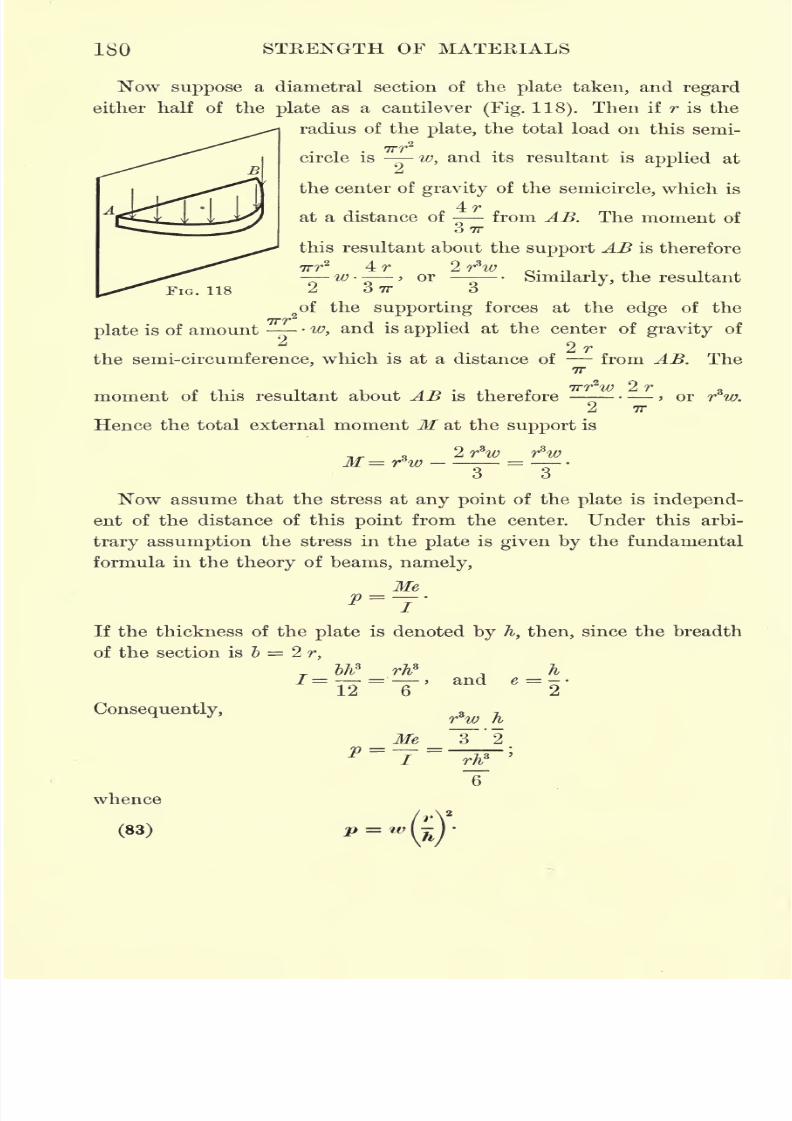
7/30/2019 Textbook on Streng 00 Slo Crich
http://slidepdf.com/reader/full/textbook-on-streng-00-slo-crich 222/433
180 STEENGTH OF MATERIALS
Now suppose a diametral section of the plate taken, and regard
either half of the plate as a cantilever (Fig. 118). Then if T is the
radius of the plate, the total load on this semi-
vrr2
circle is -w, and its resultant is applied at
the center of gravity of the semicircle, which is
4rat a distance of from AB. The moment of
3?r
this resultant about the support AB is therefore
ITf* 4 IT 2i "7* iJ}
-W- > or -
Similarly, the resultant
2 O 7T Oof the supporting forces at the edge of the
plate is of amount - -w, and is applied at the center of gravity of
2rthe semi-circumference, which is at a distance of
- - from AB. The7T
FIG. 118
Trr2
moment of this resultant about AB is thereforeTTT
ZW 2 r> or r w.
7T
Hence the total external moment M at the support is
Now assume that the stress at any point of the plate is independ-
ent of the distance of this point from the center. Under this arbi-
trary assumption the stress in the plate is given by the fundamental
formula in the theory of beams, namely,
MeP--J-
If the thickness of the plate is denoted by h, then, since the breadth
of the section is ~b = 2 r,
Consequently,
l>li* rhs h=
To'= '""' and e =
o'JLZ D
Me-
whence
(83)
7/30/2019 Textbook on Streng 00 Slo Crich
http://slidepdf.com/reader/full/textbook-on-streng-00-slo-crich 223/433
FLAT PLATES 181
Foppl has shown that the arbitrary assumption made in deriving
this formula can be avoided, and the same result obtained, by a more
rigorous analysis than the preceding; and Bach has verified the
formula experimentally. Formula (83) is therefore well established
both theoretically and practically.
Problem 249. The cylinder of a locomotive is 20 in. internal diameter. What
must be the thickness of the steel end plate if it is required to withstand a pres-
sure of 160 lb./in.2 with a factor of safety of 6 ?
Problem 250. A circular cast-iron valve gatei in. thick closes an opening 6 in.
in diameter. If the pressure against the gate is due to a water head of 150ft.,
what is the maximum stress in the gate ?
125. Maximum stress in homogeneous circular plate under con-
centrated load. Consider a flat, circular plate of homogeneous mate-
rial, and suppose that it bears a single concentrated load P which is
distributed over a small circle of radius rQconcentric with the plate.
Taking a section through the center of the plate and regarding either
half as a cantilever, as in the preceding article, the total rim pres-
P 2rsure is , and it is applied at a distance of from the center. The
p 7T
total load on the semicircle of radius r is > and it is applied at a dis-
4rtance of - from the section. Therefore the total external moment M
3-7T
at the section is
^=^_2Pn = pr/1 _2nY
7T 3-7T 7T\ 3r
Assuming
that the stress is uniformly distributed throughout the plate,
the stress due to the external moment M is given by the formula
MeP =
-j'
If the thickness of the plate is denoted by k, then
rhs h
/=_ and , = _.
Therefore f
Me ~i
whence
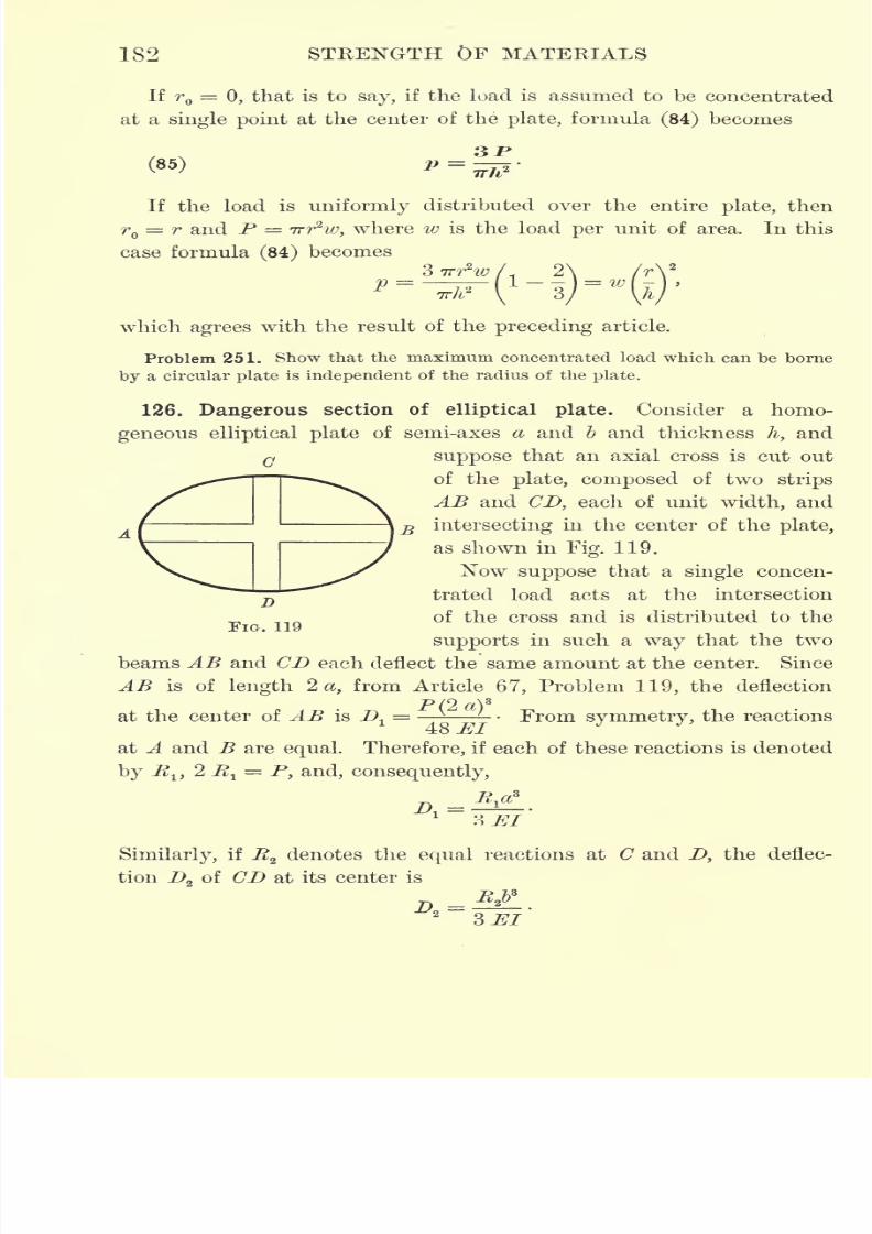
7/30/2019 Textbook on Streng 00 Slo Crich
http://slidepdf.com/reader/full/textbook-on-streng-00-slo-crich 224/433
182 STRENGTH OF MATERIALS
If r =0, that is to say, if the load is assumed to be concentrated
at a single point at the center of the plate, formula (84) becomes
(85) P =_
TTh2
If the load is uniformly distributed over the entire plate, then
= r and P = Trr*w, where w is the load per unit of area. In this
case formula (84) becomes
o
which agrees with the result of the preceding article.
Problem 251. Show that the maximum concentrated load which can be borne
by a circular plate is independent of the radius of the plate.
126. Dangerous section of elliptical plate. Consider a homo-
geneous elliptical plate of semi-axes a and b and thickness h, and
G suppose that an axial cross is cut out
of the plate, composed of two strips
AB and CD, each of unit width, and
intersecting in the center of the plate,
as shown in Fig. 119.
Now suppose that a single concen-
trated load acts at the intersection
of the cross and is distributed to the
supports in such a way that the twobeams AB and CD each deflect the same amount at the center. Since
AB is of length 2 a, from Article 67, Problem 119, the deflection
P C2 a}s
at the center of AB is Dl
- ' From symmetry, the reactions
at A and B are equal. Therefore, if each of these reactions is denoted
by R192 R^ = P, and, consequently,
3 JET
Similarly, if Rzdenotes the equal reactions at C and D, the deflec
tion !> of CD at its center is
7/30/2019 Textbook on Streng 00 Slo Crich
http://slidepdf.com/reader/full/textbook-on-streng-00-slo-crich 225/433
FLAT PLATES 183
If the plate remains intact, the two strips AB and CD must deflect
the same amount at the center. Therefore D^ = D2 ,and hence
1-5-For the beam AB of length 2 a the maximum external moment is
^3 j
R^a. Also, since AB is assumed to be of unit width, /= and e = -
Hence the maximum stress pr
in AB is
rMe , a
P'-.--.^ Bl-.
Similarly, the maximum stress prf
in CD is
*"-'*
Consequently, /
or, since from equation (86) ^= -
JU/2
y
By hypothesis, a > &. Therefore p" >y ;that is to say, the maxi-
mum stress occurs in the strip CD, or in the direction of the shorter
axis of the ellipse. In an elliptical plate, therefore, rupture may be
expected to occur along a line parallel to the major axis, a result
which has been confirmed by experiment.
127. Maximum stress in homogeneous elliptical plate under
uniform load. The method of finding the maximum stress in an
elliptical plate is to consider the two limiting forms of an ellipse,
namely, a circle and a strip of infinite length, and express a continu-
ous relation between the stresses for these two limiting forms. Themethod is therefore similar to that used in Article 88 in obtaining
the modified form of Euler's column formula.
Consider first an indefinitely long strip with parallel sides, sup-
ported at the edges and bearing a uniform load of amount w per unit
of area. Let the width of the strip be denoted by 2 b, and its thickness
7/30/2019 Textbook on Streng 00 Slo Crich
http://slidepdf.com/reader/full/textbook-on-streng-00-slo-crich 226/433
184 STRENGTH OF MATERIALS
by h. Then, if this strip is cut into cross strips of unit width, each
of these cross strips can be regarded as an independent beam, the
load on one of these unit cross strips being 2 ~bw, and the maximum
(2 5) 2 wmoment at the center being- '--- Consequently, the maximum
8
stress in the cross strips, and therefore in the original strip, is
4&V h
,-s-V"fr12
'
In the preceding article it was shown that the maximum stress in
an elliptical plate occurs in the direction of the minor axis. There-
fore equation (87) gives the limiting value which the stress in an
elliptical plate approaches as the ellipse becomes more and more
elongated.
For a circular plate of radius b and thickness h the maximum
stress was found to be
(S8) ,-
Comparing equations (87) and (88), it is evident that the maximum
stress in an elliptical plate is given, in general, by the formula
where & is a constant which lies between 1 and 3. Thus, for - =1,
~b
a
that is, for a circle, k = 1; whereas, if
-0, that is, for an infinitely
CL
long ellipse,k = 3. The constant k may therefore be assumed to
have the value
&=3-2->a
which reduces to the values 1 and 3 for the limiting cases, and in
other cases has an intermediate value depending on the form of the
plate. Consequently,
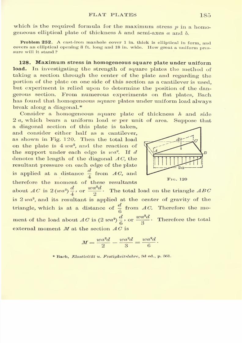
7/30/2019 Textbook on Streng 00 Slo Crich
http://slidepdf.com/reader/full/textbook-on-streng-00-slo-crich 227/433
FLAT PLATES 185
which is the required formula for the maximum stress p in a homo-
geneous elliptical plate of thickness h and semi-axes a and &.
Problem 252. A cast-iron manhole cover 1 in. thick is
ellipticalin
form, andcovers an elliptical opening 3 ft. long and 18 in. wide. How great a uniform pres-
sure will it stand ?
128. Maximum stress in homogeneous square plate under uniform
load. In investigating the strength of square plates the method of
taking a section through the center of the plate and regarding the
portion of the plate on one side of this section as a cantilever is used,
but experiment is relied upon to determine the position of the dan-
gerous section. From numerous experiments on flat plates, Bach
has found that homogeneous square plates under uniform load always
break along a diagonal.*
Consider a homogeneous square plate of thickness h and side
2 a, which bears a uniform load w per unit of area. Suppose that
a diagonal section of this plate is taken,
and consider either half as a cantilever,
as shown in Fig. 120. Then the total load
on the plate is 4wa2
,and the reaction of
the support under each edge is wa\ If d
denotes the length of the diagonal AC, the
resultant pressure on each edge of the plate
is applied at a distance from AC, and
therefore the moment of these resultantsFIG. 120
about AC is 2 (wa2
)
-> or The total load on the triangle ABC
is 2 wa2
,and its resultant is applied at the center of gravity of the
triangle, which is at a distance of - from AC. Therefore the mo-
7 2>-7
ment of the load about AC is(2 wa
2
)
-> or ^ - Therefore the total
6 3external moment M at the section AC is
wa2d wa2d wa2d
*Bach, Elasticitat u. Festigkeitslehre, 3d ed., p. 561.
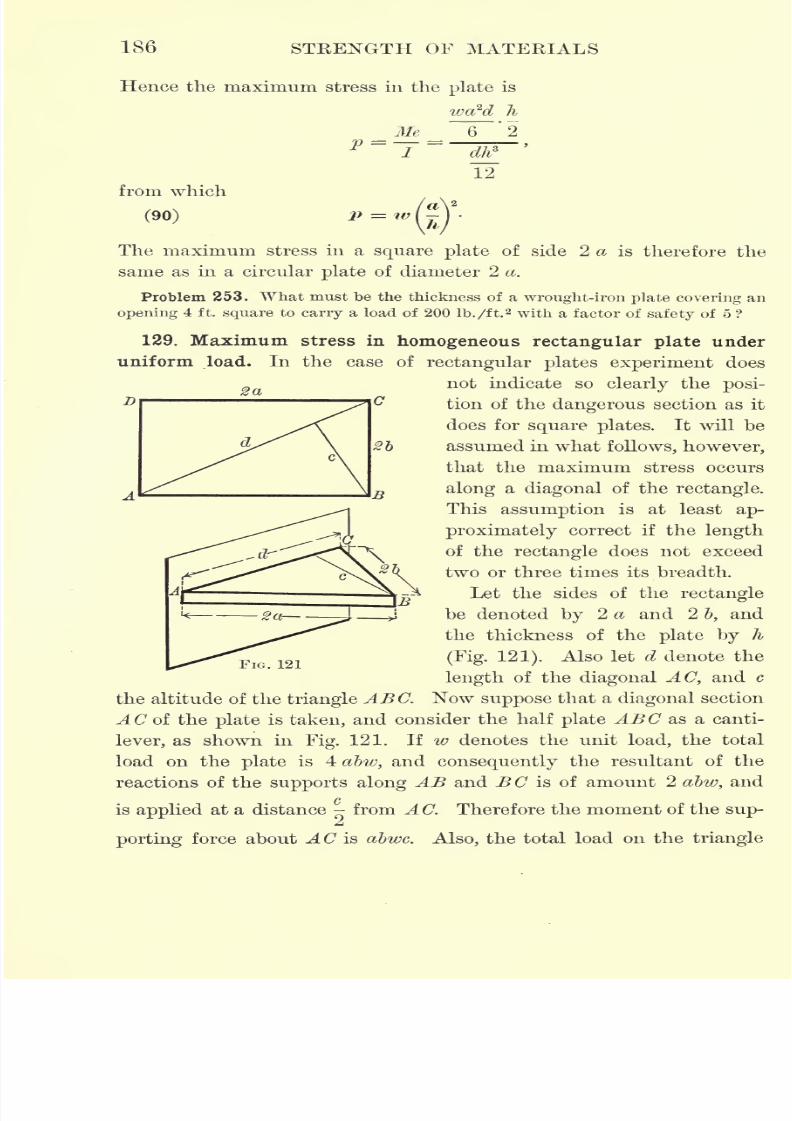
7/30/2019 Textbook on Streng 00 Slo Crich
http://slidepdf.com/reader/full/textbook-on-streng-00-slo-crich 228/433
186 STRENGTH OF MATERIALS
Hence the maximum stress in the plate is
h
2
from which
(90)
D
The maximum stress in a square plate of side 2 a is therefore the
same as in a circular plate of diameter 2 a.
Problem 253. What must be the thickness of a wrought-iron plate covering an
opening 4 ft. square to carry a load of 200 lb./ft.2 with a factor of safety of 5 ?
129. Maximum stress in homogeneous rectangular plate under
uniform load. In the case of rectangular plates experiment does
Sanot indicate so clearly the posi-
tion of the dangerous section as it
does for square plates. It will be
assumed in what follows, however,
that the maximum stress occurs
along a diagonal of the rectangle.
This assumption is at least ap-
proximately correct if the length
of the rectangle does not exceed
two or three times its breadth.
Let the sides of the rectangle
be denoted by 2 a and 2 b, and
the thickness of the plate by h
(Fig. 121). Also let d denote the
length of the diagonal AC, and c
the altitude of the triangle ABC. Now suppose that a diagonal section
AC of the plate is taken, and consider the half plate ABC as a canti-
lever, as shown in Fig. 121. If w denotes the unit load, the total
load on the plate is 4 abw, and consequently the resultant of the
reactions of the supports along AB and BC is of amount 2 abw, and/>
is applied at a distance from A C. Therefore the moment of the sup-
porting force about AC is abwc. Also, the total load on the triangle
FIG. 121
7/30/2019 Textbook on Streng 00 Slo Crich
http://slidepdf.com/reader/full/textbook-on-streng-00-slo-crich 229/433
FLAT PLATES 187
ABC is 2 abw, and it is applied at the center of gravity of the triangle,
which is at a distance of - from A C. Consequently, the total momento
of the load about A C is -
-- Therefore the total external moment
M at the section A C is
2 abwc abwcM abwc - = ->
o o
and the maximum stress in the plate is
abwc li
_Me__ 3
'
2 _ 2 wale
p''
i''
dtf ~dhT12
or, since cd = 4 ab,
which gives the required maximum stress.
For a square plate a = b and c = a V2, and formula (91) reduces
to formula (90) for square plates, obtained in the preceding article.
Problem 254. A wrought-iron trapdoor is 5 ft. long, 3 ft. wide, and f in. thick.
How great a uniform load will it bear ?
130. Non-homogeneous plates ; concrete-steel floor panels. The
formulas derived in the preceding articles apply only to flat plates of
homogeneous material. If a plate is composed of non-homogeneous
material, such as reenforced concrete, the maximum stress is given by
the formula -
,
where /' is the moment of inertia of the equivalent homogeneous
section obtained from the non-homogeneous section as explained in
Article 48, and e' is the distance of the extreme fiber of this equivalent
homogeneous section from its neutral axis.
Thus,from Article
124,the external moment
Mon half of a uni-
*7* ijf)
formly loaded circular plate is M = > and, consequently, the maxi-o
mum stress in a uniformly loaded, non-homogeneous, circular plate is
given by the formula
7/30/2019 Textbook on Streng 00 Slo Crich
http://slidepdf.com/reader/full/textbook-on-streng-00-slo-crich 230/433
188 STRENGTH OF MATERIALS
where I1 and ef
refer to the equivalent homogeneous section as
explained above, and this section is taken through the center of
the plate.
Similarly, from Article 128, the maximum stress in a uniformly
loaded, non-homogeneous, square plate of side 2 a is given by the
formula
/no\(93) ,
and, from Article 129, the maximum stress in a uniformly loaded, non-
homogeneous,rectangular plate of sides 2 a and 2 I
by
the formula
abwce'
(94) p =31'
in which er
and /' refer to the equivalent homogeneous section obtained
from a diagonal section of the plate.
Problem 255. A concrete-steel floor panel is 18 ft. long, 15 ft. wide, and 4 in.
thick,and is reenforced
by square wrought-ironrods 1 in.
thick, placedof
aninch from the bottom of the slab and spaced 1 ft. apart. Find the maximum stress
in the panel under a total live and dead load of 150 lb./ft.2
.
NOTE. Take a diagonal section of the panel and calculate the equivalent homogeneoussection corresponding to it. Then find the position of the neutral axis of this equivalent
homogeneous section, and its moment of inertia about this neutral axis, as explained in
Article 48. The maximum stress can then be obtained from formula (94).
Problem 256. Design a floor panel 14 ft. square, to be made of reenforced
concrete and to sustain a total uniform load of 120 lb./ft.a with a factor of safety
of 4.
EXERCISES ON CHAPTER VHI
Problem 257. The steel diaphragm separating two expansion chambers of a
steam turbine is subjected to a pressure of 150 lb./in.2 on one side and 801b./in.
2
on the other. Find the required thickness for a factor of safety of 10.
Problem 258. The cylinder of an hydraulic press is made of cast steel, 10 in.
inside diameter, with a flat end of the same thickness as the walls of the cylinder.
Find the required thickness for a factor of safety of 20. Also find how much larger
the factor of safety would be if the end was made hemispherical instead of flat.
Problem 259. The cylinder of a steam engine is 16 in. inside diameter and
carries a steam pressure of 125 lb./in.2 If the cylinder head is mild steel, find its
thickness for a factor of safety of 10.
Problem 260. A cast-iron valve gate 10 in. in diameter is under a pressure
head of 200 ft. Find its thickness for a factor of safety of 15.
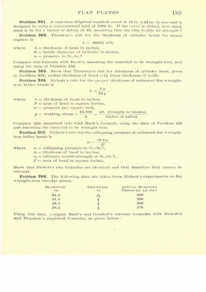
7/30/2019 Textbook on Streng 00 Slo Crich
http://slidepdf.com/reader/full/textbook-on-streng-00-slo-crich 231/433
FLAT PLATES 189
Problem 261. A cast-iron elliptical manhole cover is 18 in. x 24 in. in size and is
designed to carry a concentrated load of 1000 Ib. If the cover is ribbed, how thick
must it be for a factor of safety of 20, assuming that the ribs double its strength ?
Problem 262. Thurston's rule for the thickness of cylinder heads for steam
engines is
h = .00035 wD,
where h = thickness of head in inches,
1} = inside diameter of cylinder in inches,
w = pressure in lb./in.2
Compare this formula with Bach's, assuming the material to be wrought iron, and
using the data of Problem 259.
Problem 263. Show that Thurston's rule for thickness of cylinder head, given
in Problem 262, makes thickness of head =11 times thickness of walls.
Problem 264. Nichols's rule for the proper thickness of unbraced flat wrought-
iron boiler heads is
_ Fw
"Top'
where h = thickness of head in inches,
jP area of head in square inches,
w = pressure per square inch,
44,800 ult. strength in tension
p = working stress = 8 factor of safety
Compare this empirical rule with Bach's formula, using the data of Problem 259
and assuming the material to be wrought iron.
Problem 265. Nichols's rule for the collapsing pressure of unbraced flat wrought-
iron boiler heads is
_ 10 hut
where w = collapsing pressure in lb./in.2
,
h = thickness of head in inches,
ut= ultimate tensile strength in lb./in.
2,
F area of head in square inches.
Show that Nichols's two formulas are identical and that therefore they cannot be
rational.
Problem 266. The following data are taken from Nichols's experiments on flat
wrought-iron circular plates.
DIAMETER
IN.
34.6
34.5
28.5
26.5
Using this data, compare Bach's and Grashof's rational formulas with Nichols's
and Thurston's empirical formulas, as given below:
THICKNESS
7/30/2019 Textbook on Streng 00 Slo Crich
http://slidepdf.com/reader/full/textbook-on-streng-00-slo-crich 232/433
1(JO STRENGTH OF MATEKIALS
Circular plate, supported at edge and uniformly loaded.
Bach,P
Grashof, h== .4564 ,
\ Qp \p
Nichols, ^=^lOp
Thurston, A = .00035 w>Z>,
where /i = thickness of head in inches,
D = diameter of head in inches = 2r,
w = pressure in lb./in.2
,
p = working stress in lb./in.2
,
F = area of head in square inches =
Note that the Nichols and Thurston formulas apply only to wrought iron.
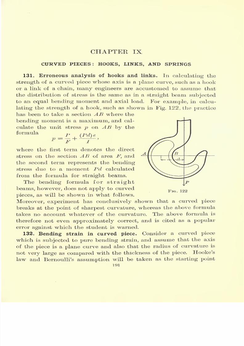
7/30/2019 Textbook on Streng 00 Slo Crich
http://slidepdf.com/reader/full/textbook-on-streng-00-slo-crich 233/433
CHAPTER IX
CURVED PIECES: HOOKS, LINKS, AND SPRINGS
131. Erroneous analysis of hooks and links. In calculating the
strength of a curved piece whose axis is a plane curve, such as a hook
or a link of a chain, many engineers are accustomed to assume that
the distribution of stress is the same as in a straight beam subjected
to an equal bending moment and axial load. For example, in calcu-
lating the strength of a hook, such as shown in Fig. 122, the practice
has been to take a section AB where the
bending moment is a maximum, and cal-
culate the unit stress p on AB by the
formula
p (pd)gP = h
F I
where the first term denotes the direct
stress on the section AB of area F, and
the second term represents the bending
stress due to a moment Pd calculated
from the formula for straight beams.
The bending formula for straight
beams, however, does not apply to curved
pieces, as will be shown in what follows.
Moreover, experiment has conclusively shown that a curved piece
breaks at the point of sharpest curvature, whereas the above formula
takes no account whatever of the curvature. The above formula is
therefore not even approximately correct, and is cited as a popular
error against which the student is warned.
132. Bending strain in curved piece. Consider a curved piece
which is subjected to pure bending strain, and assume that the axis
of the piece is a plane curve and also that the radius of curvature is
not very large as compared with the thickness of the piece. Hooke's
law and Bernoulli's assumption will be taken as the starting point
191
FIG. 122
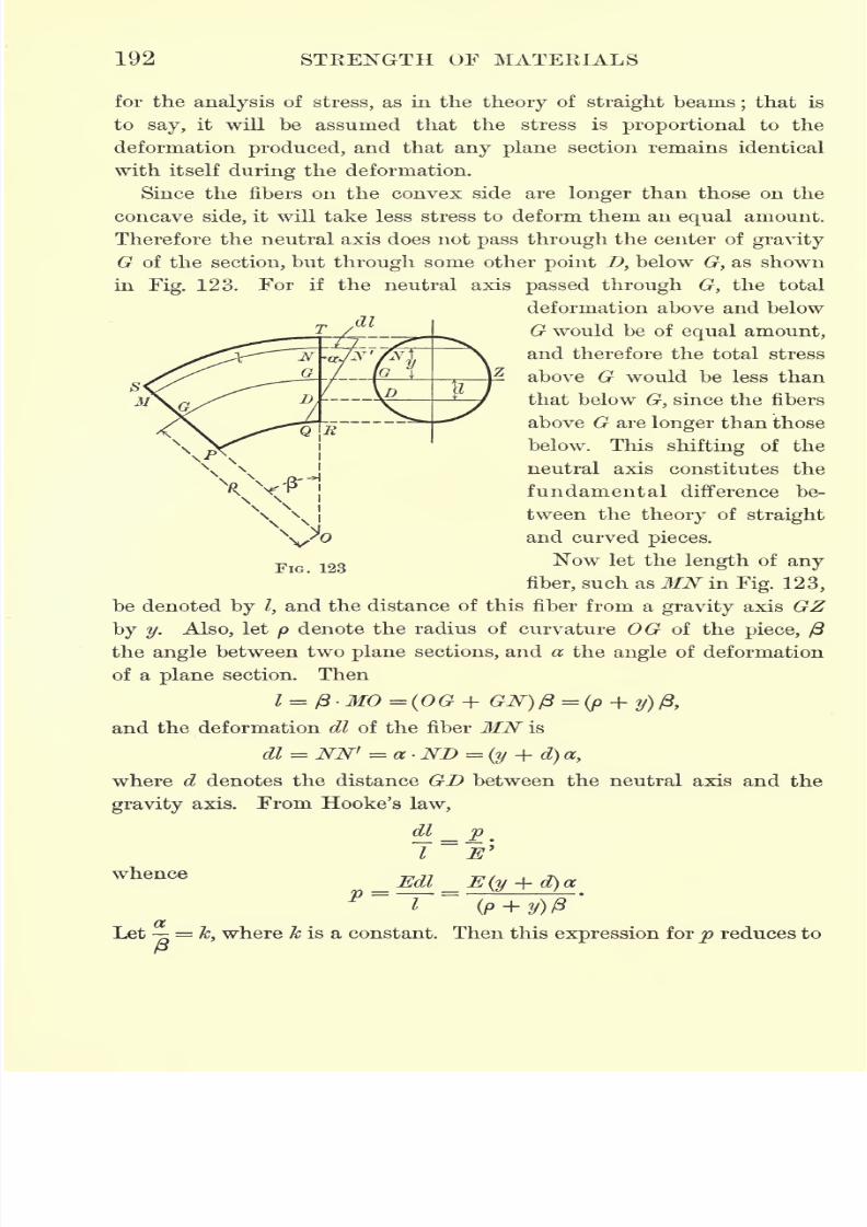
7/30/2019 Textbook on Streng 00 Slo Crich
http://slidepdf.com/reader/full/textbook-on-streng-00-slo-crich 234/433
192 STRENGTH OF MATERIALS
for the analysis of stress, as in the theory of straight beams;that is
to say, it will be assumed that the stress is proportional to the
deformation produced, and that any plane section remains identical
with itself during the deformation.
Since the fibers on the convex side are longer than those on the
concave side, it will take less stress to deform them an equal amount.
Therefore the neutral axis does not pass through the center of gravity
G of the section, but through some other point D, below G, as shown
in Fig. 123. For if the neutral axis passed through G, the total
deformation above and below
G would be of equal amount,
and therefore the total stress
above G would be less than
that below G, since the fibers
above G are longer than those
below. This shifting of the
neutral axis constitutes the
fundamental difference be-
tween the theory of straight
and curved pieces.
Now let the length of any
fiber, such as MN in Fig. 123,
be denoted by Z,and the distance of this fiber from a gravity axis GZ
byy. Also, let
p
denote the radius of curvature OG of the piece, j3
the angle between two plane sections, and a the angle of deformation
of a plane section. Then
1 = /3>MO = (OG + GN)/3=(p + y)/3t
and the deformation dl of the fiber MN is
dl = NN' = a ND =(y + d) a,
where d denotes the distance GD between the neutral axis and the
gravity axis. From Hooke's law,
v Jit
_ Edl _ E(y + d)a
~~r (o-
whence
Let =Jc, where & is a constant. Then this expression for p reduces to
P
7/30/2019 Textbook on Streng 00 Slo Crich
http://slidepdf.com/reader/full/textbook-on-streng-00-slo-crich 235/433
HOOKS, LINKS, AND SPRINGS 193
(95) p^Ek^t+A.y + p
Under the
assumption
of
pure bendingstrain the shear is zero
and the normal stresses form a couple. Therefore the algebraic sum
of the normal stresses is zero;that is to say,
pdF = 0,
or, substituting the value of p from equation (95),
y + p
Since k and E are constants and not zero, the integral must be zero.
Therefore, separating the integral into parts,
y + p
whence
r
OB) d=- J y+pdF
+ P
which gives the distance of the neutral axis below the center of
gravity of the section.
Now let M denote the external bending moment acting on any
given section of area F, dF an infinitesimal area taken anywhere in
this section, p the stress acting on it, and y its distance from the
gravity axis GZ. Then
or, substituting the value of p from equation (95),
y
consequently
k =
y + pand hence
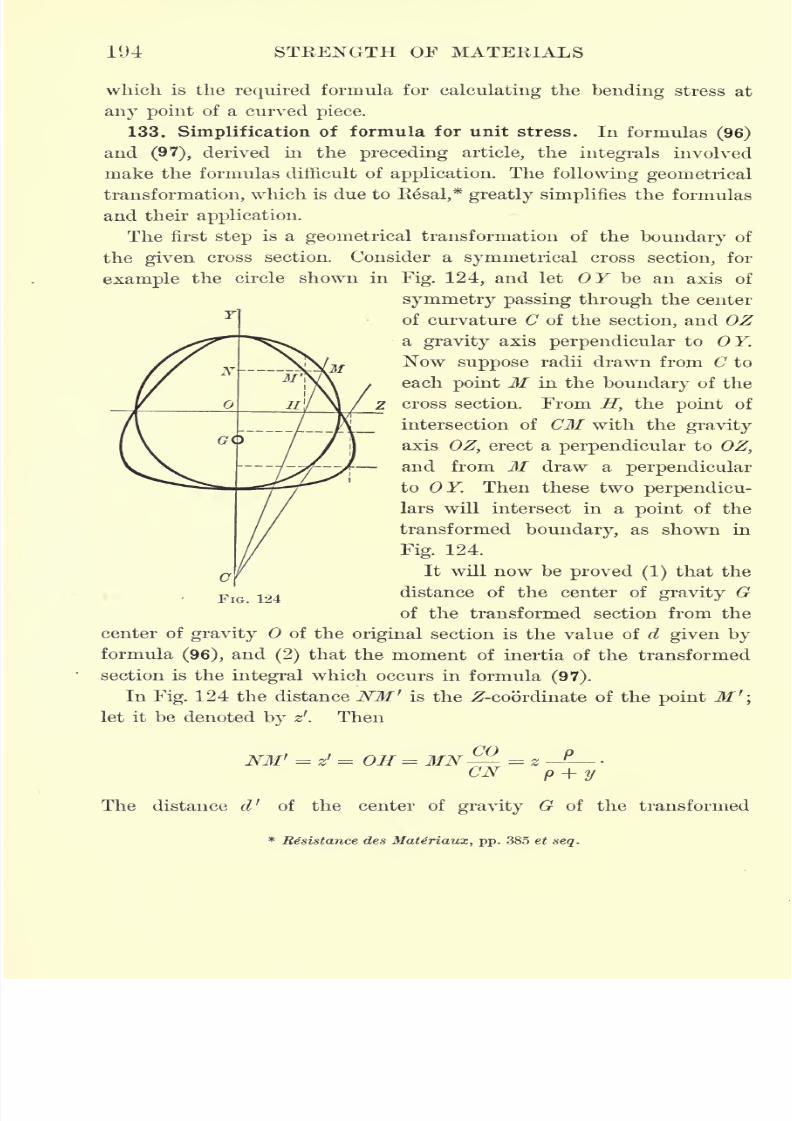
7/30/2019 Textbook on Streng 00 Slo Crich
http://slidepdf.com/reader/full/textbook-on-streng-00-slo-crich 236/433
194 STRENGTH OF MATERIALS
which is the required formula for calculating the bending stress at
any point of a curved piece.
133. Simplification of formula for unit stress. In formulas (96)
and (97), derived in the preceding article, the integrals involved
make the formulas difficult of application. The following geometrical
transformation, which is due to Resal,* greatly simplifies the formulas
and their application.
The first step is a geometrical transformation of the boundary of
the given cross section. Consider a symmetrical cross section, for
example the circle shown in Fig. 124, and let OF be an axis of
symmetry passing through the center
of curvature C of the section, and OZ
a gravity axis perpendicular to OY.
Now suppose radii drawn from C to
each point M in the boundary of the
cross section. From H, the point of
intersection of CM with the gravity
axis OZ, erect a perpendicular to OZ,
and from M draw a perpendicular
to OY. Then these two perpendicu-
lars will intersect in a point of the
transformed boundary, as shown in
Fig. 124.
It will now be proved (1)that the
distance of the center of gravity G
of the transformed section from the
center of gravity of the original section is the value of d given by
formula (96), and(2)
that the moment of inertia of the transformed
section is the integral which occurs in formula (97).
In Fig. 124 the distance NM' is the ^-coordinate of the point M '
let it be denoted by zf
. Then
NM' = z' = OH = MN = z
CN p + y
The distance d' of the center of gravity G of the transformed
Resistance des Mate'riaux, pp. 385 et seq.
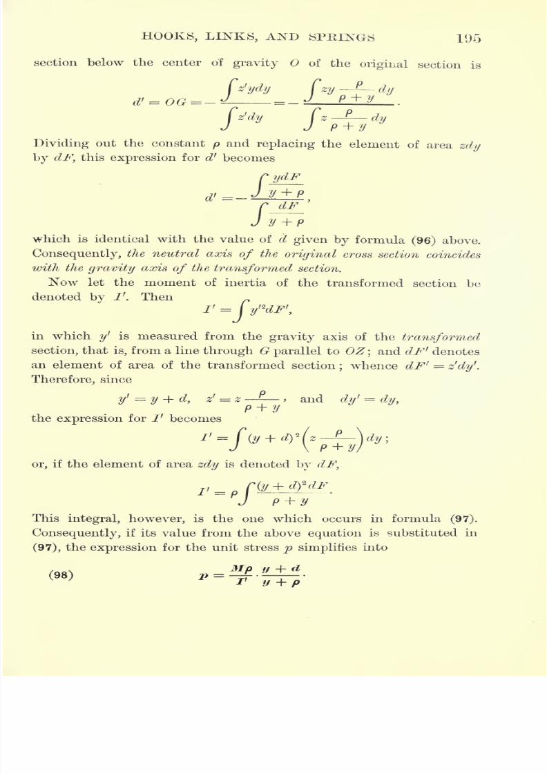
7/30/2019 Textbook on Streng 00 Slo Crich
http://slidepdf.com/reader/full/textbook-on-streng-00-slo-crich 237/433
HOOKS, LINKS, AND SPRINGS 195
section below the center o'f gravity of the original section is
zy-
dy
Cz'dy Cz-f
J J p + ydy
Dividing out the constant p and replacing the element of area zdy
by dF, this expression for d' becomes
y + p
which is identical with the value of d given by formula (96) above.
Consequently, the neutral axis of the original cross section coincides
with the gravity axis of the transformed section.
Now let the moment of inertia of the transformed section be
denoted
byI'. Then
in which y' is measured from the gravity axis of the transformed
section, that is, from a line through G parallel to OZ;and dF' denotes
an element of area of the transformed section;whence dF ! =
zdy'.
Therefore, since
y'
=y + d,
z' = z -> and
dy'
=dy,p + y
the expression for /' becomes
or, if the element of area zdy is denoted by dF,
!< = pr(y + ^dF
J p + yThis integral, however, is the one which occurs in formula (97).
Consequently, if its value from the above equation is substituted in
(97), the expression for the unit stress p simplifies into
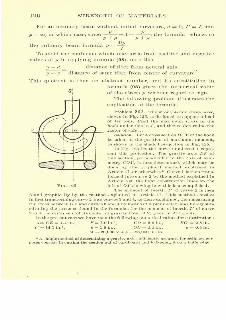
7/30/2019 Textbook on Streng 00 Slo Crich
http://slidepdf.com/reader/full/textbook-on-streng-00-slo-crich 238/433
196 STEENGTH OF MATEEIALS
For an ordinary beam without initial curvature, d = 0, Ir =
J, and
p = oo, in which case, since = 1- y
y+p p y
My
, the formula reduces to
the ordinary beam formula p = -
To avoid the confusion which may arise from positive and negative
values of y in applying formula(98), note that
y + d distance of fiber from neutral axis
y + p distance of same fiber from center of curvature
Thisquotient
is then an abstract
number,and its substitution in
formula(98) gives the numerical value
-I of the stress p without regard to sign.
The following problem illustrates the
application of the formula.
Problem 267. The wrought-iron crane hook,
shown in Fig. 125, is designed to support a load
of ten tons. Find the maximum stress in the
hook under this load, and thence determine the
factor of safety.
Solution. Let a cross section OCF of the hook
be taken at the position of maximum moment,
as shown in the shaded projection in Fig. 125.
In Fig. 126 let the curve numbered 1 repre-
sent this projection. The gravity axis DF of
this section, perpendicular to the axis of sym-
metry COF, is first determined, which may be
done by the graphical method explained in
Article 47, or otherwise.* Curve 1 is then trans-
formed into curve 2 by the method explained in
Article 133, the light construction lines on the
left of OF showing how this is accomplished.
The moment of inertia I' of curve 2 is then
found graphically by the method explained in Article 47. This method consists
in first transforming curve 2 into curves 3 and 4, as there explained, then measuring
the areas between OF and curves 3 and 4 by means of a planimeter, and finally sub-
stituting the areas so found in the formulas for the moment of inertia I' of curve
2 and the distance c of its center of gravity from AB, given in Article 47.
In the present case we have then the following numerical values for substitution :
p=C# = 4.4in., F=7.9in. 2,
CO = 2.2 in., EO' = 2.8 in.,
M= 20,000 x 4.4 = 88,000 in. Ib.
* A simple method of determining a gravity axis sufficiently accurate for ordinary pur-
poses consists in cutting the section out of cardboard and balancing it on a knife edge.
FIG. 125
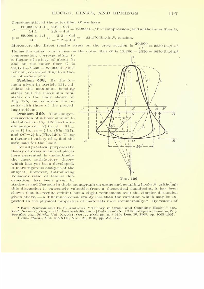
7/30/2019 Textbook on Streng 00 Slo Crich
http://slidepdf.com/reader/full/textbook-on-streng-00-slo-crich 239/433
HOOKS, LINKS, AND SPRINGS 197
Consequently, at the outer fiber O' we have
88,000 x 4.4 2.8 + 0.4x = 1 2,200 lb./ in.
2compression; and at the inner fiber 0,
=
p =
14.1
88,000 x
_ = - 22,470 lb./i,,., tension.
Moreover, the direct tensile stress on the cross section is20,000
7.9
= 2530 lb./in.'
Hence the actual total stress on the outer fiber O' is 12,200 2530 = UG70 lb./in.s
compression, corresponding to
a factor of safety of about 5;
and on the inner fiber is
22,470 + 2530 = 25,000 lb./in.2
tension, corresponding to a fac-
tor of safety of 2.
Problem 268. By the for-
mula given in Article 131, cal-
culate the maximum bending
stress and the maximum total
stress on the hook shown in
Fig. 125, and compare the re-
sults with those of the preced-
ing problem.
Problem 269. The danger-
ous section of a hook similar to
that shown in Fig. 125 has for its
dimensions b = 2| in., h = Q in.,
ri = If in., r2 = fin. (Fig. 127),
and OC= 2| in. (Fig. 126). Using
a factor of safety of 4, find the
safe load for the hook.
For all practical purposes the
theory of stress in curved pieces
here presented is undoubtedly
the most satisfactory theory
which has yet been developed.
A more rigorous analysis of the
subject, however, introducing
Poisson's ratio of lateral def-
ormation, has been given by
Andrews and Pearson in their monograph on crane and coupling hooks.* Although
this discussion is extremely valuable , from a theoretical standpoint, it has been
shown that its results exhibit but a slight refinement over the simpler discussion
given above, a difference considerably less than the variation which may be ex-
pected in the physical properties of materials used commercially.! By reason of
* Karl Pearson and E. H. Andrews, "Theory in Crane and Coupling Hooks," etc.,
Tech. Series I; J)rapers Co. Research Memoirs [Dulau and Co., 37 Soho Square, London,W.],See also Am. Much., Vol. XXXII, Oct. 7, 1909, pp. 615-619; Dec. 16, 1909, pp. 1065-1067.
t Am. Much., Vol. XXXIII, Nov. 24, 1910, pp. 954-955.
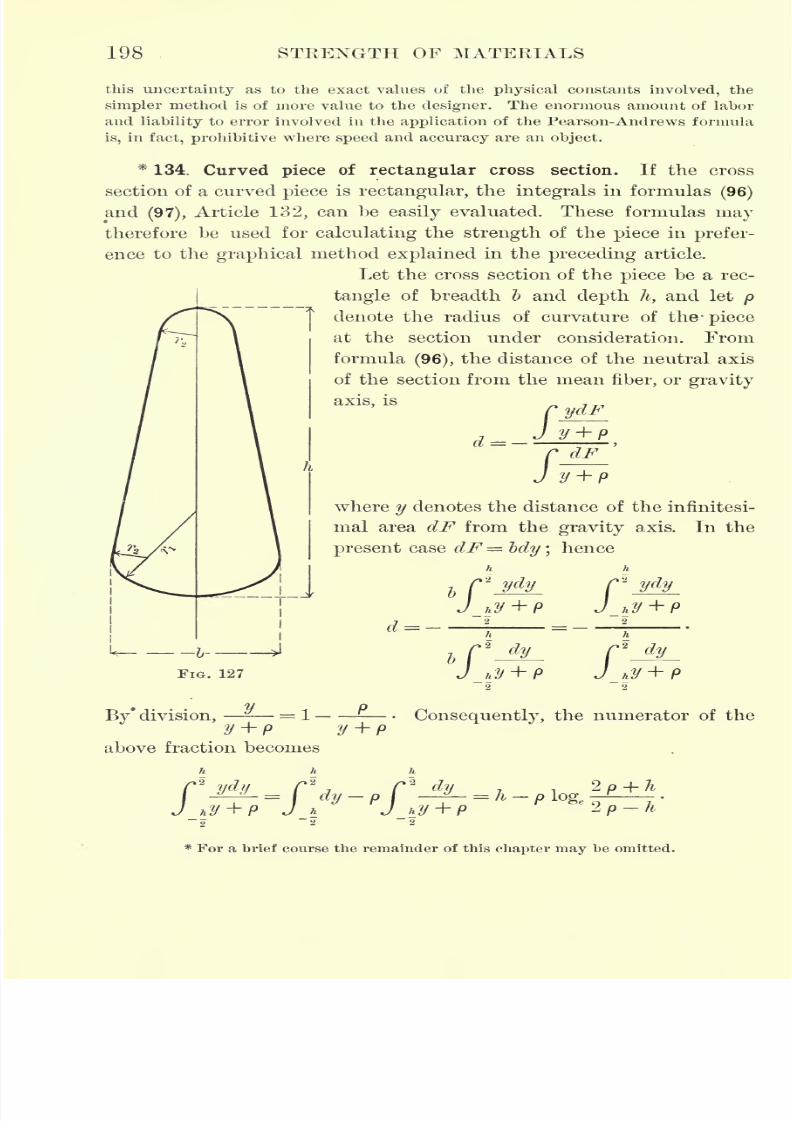
7/30/2019 Textbook on Streng 00 Slo Crich
http://slidepdf.com/reader/full/textbook-on-streng-00-slo-crich 240/433
198 STRENGTH OF MATERIALS
this uncertainty as to the exact values of the physical constants involved, the
simpler method is of more value to the designer. The enormous amount of labor
and liability to error involved in the application of the Pearson-Andrews formula
is,in fact, prohibitive where speed and accuracy are an object.
*134. Curved piece of rectangular cross section. If the cross
section of a curved piece is rectangular, the integrals in formulas(96)
and(97),
Article 132, can be easily evaluated. These formulas may
therefore be used for calculating the strength of the piece in prefer-
ence to the graphical method explained in the preceding article.
Let the cross section of the piece be a rec-
tangle of breadth b and depth h, and let p
denote the radius of curvature of the1
piece
at the section under consideration. From
formula (96), the distance of the neutral axis
of the section from the mean fiber, or gravity
axis, is
JI
y + p
where y denotes the distance of the infinitesi-
mal area dF from the gravity axis. In the
present case dF= Idy ;hence
n n
>
C2
ydy r*I , y -\- n I
,is h u '
i is h
FIG. 127f*
dy r\I 7 H -h D / i
'
*/ h,y ' r i/ hi
dy
By* division,- = 1 Consequently, the numerator of the
y+p y+pabove fraction becomes
rJ
* For a brief course the remainder of this chapter may be omitted.
7/30/2019 Textbook on Streng 00 Slo Crich
http://slidepdf.com/reader/full/textbook-on-streng-00-slo-crich 241/433
HOOKS, LINKS, AND SPRINGS
Similarly, the denominator becomes
19!)
Consequently,
8
dy
y + p
d=-
+p) 2 p h
"2p-hh
which may be written
(99) d = p -
>e
2p-h
h
h
2p-h
From formula (97), Article 132, the unit stress^? at any point in the
cross section, distant y from the mean fiber, is given by the equation
M(y + d)
(y + p)
(y
dF
Replacing dF by ~bdy,and separating the integral in the denominator
into partial integrals by means of division, this integral becomes
-
Substituting for d its value from equation (99), this expression
finally reduces to
y + pp-
2/o hj
= bhd.
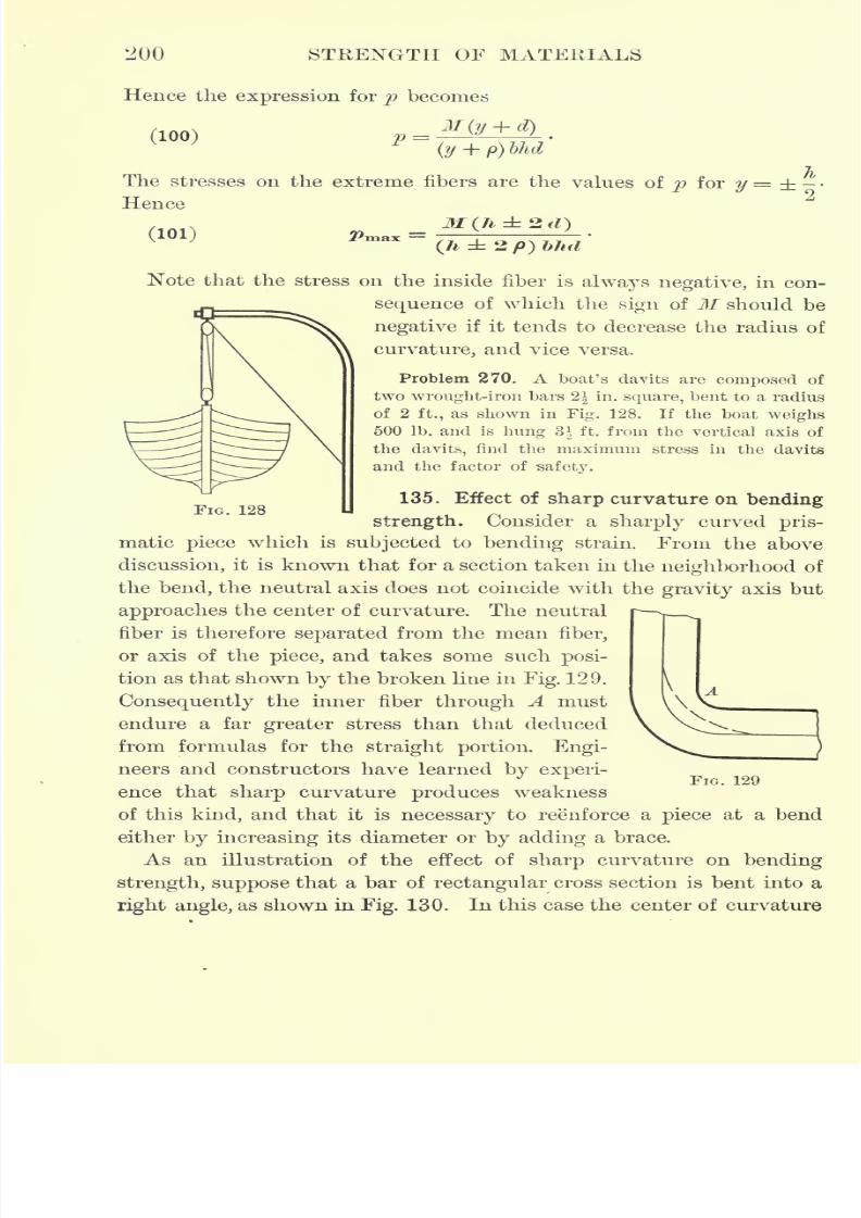
7/30/2019 Textbook on Streng 00 Slo Crich
http://slidepdf.com/reader/full/textbook-on-streng-00-slo-crich 242/433
STRENGTH OF MATERIALS
Hence the expression for p becomes
(100)
The stresses on the extreme fibers are the values of p for y =
Hence
(101)
FIG. 128
(7*, 2/9) bhd
Note that the stress on the inside fiber is always negative, in con-
sequence of which the sign of M should be
negative if it tends to decrease the radius of
curvature, and vice versa.
Problem 270. A boat's davits are composed of
two wrought-iron bars 2| in. square, bent to a radius
of 2ft., as shown in Fig. 128. If the boat weighs
500 Ib. and is hung 3} ft. from the vertical axis of
the davits, find the maximum stress in the davits
and the factor of -safety.
135. Effect of sharp curvature on bending
strength. Consider a sharply curved pris-
matic piece which is subjected to bending strain. From the above
discussion, it is known that for a section taken in the neighborhood of
the bend, the neutral axis does not coincide with the gravity axis but
approaches the center of curvature. The neutral
fiber is therefore separated from the mean fiber,
or axis of the piece, and takes some such posi-
tion as that shown by the broken line in Fig. 129. \
Consequently the inner fiber through A must \ \\
endure a far greater stress than that deduced
from formulas for the straight portion. Engi-
neers and constructors have learned by experi-
ence that sharp curvature produces weaknessof this kind, and that it is necessary to reenforce a piece at a bend
either by increasing its diameter or by adding a brace.
As an illustration of the effect of sharp curvature on bending
strength, suppose that a bar of rectangular cross section is bent into a
right angle, as shown in Fig. 130. In this case the center of curvature
FIG. 129

7/30/2019 Textbook on Streng 00 Slo Crich
http://slidepdf.com/reader/full/textbook-on-streng-00-slo-crich 243/433
HOOKS, LINKS, AND SPRINGS 201
of the mean fiber BC is at A. Therefore, if h denotes the thickness
of the piece, the radius of curvature of BC is
p= -
Consequently,2 + h 2k
and hence formula (99) becomes
hd = p = -.
FIG. 130
Therefore the neutral fiber passes through the ver-
tex of the angle A, and consequently a piece of
this kind can offer no resistance to bending. In other words, if a
piece is bent exactly at right angles on itself, the slightest bending
strain must produce incipient rupture.
This example is useful, then, in pointing out the danger of sharp
curvature and showing how rapidly the strength decreases with the
radius of curvature.
136. Maximum moment in circular piece. Consider a prismatic
piece with a circular axis, such as a ring or a section of pipe,
and suppose that it is
subjected to two equal
and opposite forces
P, either of tension
or compression, act-
ing along a diameter
as shown in Fig. 131.
Draw a second diam-
eter MN at right an-
gles to the direction
in which the forces P
act. Since these two
diameters divide the
figure into four symmetrical parts, it is only necessary to consider one
of these parts, say the upper left-hand quadrant. The forces acting on
any section of this quadrant consist of a single force and a moment.
pOn the base CD of the quadrant this single force is of amount >
2
FIG.131
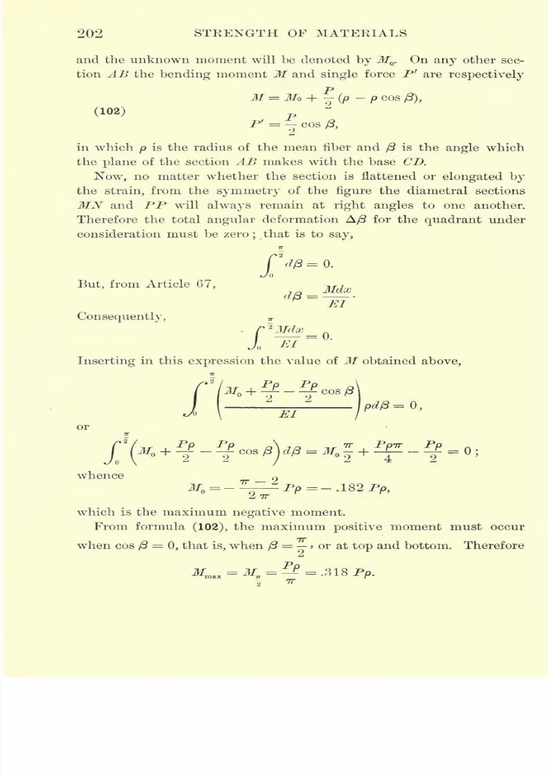
7/30/2019 Textbook on Streng 00 Slo Crich
http://slidepdf.com/reader/full/textbook-on-streng-00-slo-crich 244/433
202 STRENGTH OF MATERIALS
and the unknown moment will be denoted by Jf . On any other sec-
tion AB the bending moment M and single force P' are respectively
M=M*+j{p -pcaa/3),(102) p
P' = - cos A
in which p is the radius of the mean fiber and /? is the angle which
the plane of the section AB makes with the base CD.
Now, no matter whether the section is flattened or elongated by
the strain, from the symmetry of the figure the diametral sections
MN and PP will always remain at right angles to one another.
Therefore the total angular deformation A/3 for the quadrant under
consideration must be zero;that is to say,
But, from Article 67,
Consequently,
MI
= 0.
El
Inserting in this expression the value of M obtained above,
or
pd/3=0,
7T
Jo \
whenceTT A
which is the maximum negative moment.
From formula (102), the maximum positive moment must occur
when cos ft=
0, that is, when /3= > or at top and bottom. Therefore
^naX= ^ = =-318 Pp.
7T
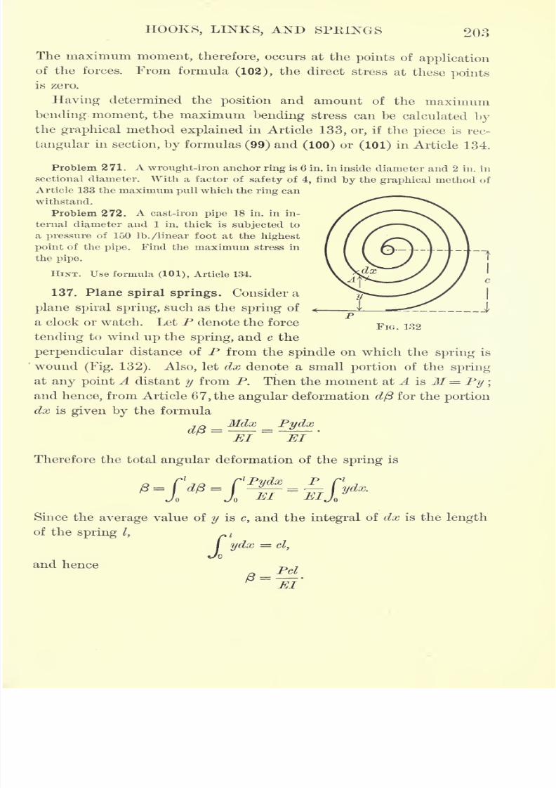
7/30/2019 Textbook on Streng 00 Slo Crich
http://slidepdf.com/reader/full/textbook-on-streng-00-slo-crich 245/433
HOOKS, LINKS, AND SPRINGS 203
The maximum moment, therefore, occurs at the points of application
of the forces. From formula (102), the direct stress at these points
is zero.
Having determined the position and amount of the maximumbending- moment, the maximum bending stress can be calculated bythe graphical method explained in Article 133, or, if the piece is rec-
tangular in section, by formulas (99) and (100) or (101) in Article 134.
Problem 271. A wrought-iron anchor ring is 6 in. in inside diameter and 2 in. in
sectional diameter. With a factor of safety of 4, find by the graphical method of
Article 133 the maximum pull which the ring can
withstand.
Problem 272. A cast-iron pipe 18 in. in in-
ternal diameter and 1 in. thick is subjected to
a pressure of 150 Ib. /linear foot at the highest
point of the pipe. Find the maximum stress in
the pipe.
HINT. Use formula (101), Article 134.
137. Plane spiral springs. Consider a
plane spiral spring, such as the spring of
a clock or watch. Let P denote the force
tending to wind up the spring, and c the
perpendicular distance of P from the spindle on which the spring is
wound(Fig. 132). Also, let dx denote a small portion of the spring
at any point A distant y from P. Then the moment at A is M= Py ;
and hence, from Article 6 7, the angular deformation dp for the portion
dx is given by the formula
-jo _ Mdx _ Pydx~~&T
~T?T
'
Jiil M/l
Therefore the total angular deformation of the spring is
FIG. 132
Since the average value of y is c, and the integral of dx is the length
of the spring I,~
l
I ydx = cl,
Joand hence
7
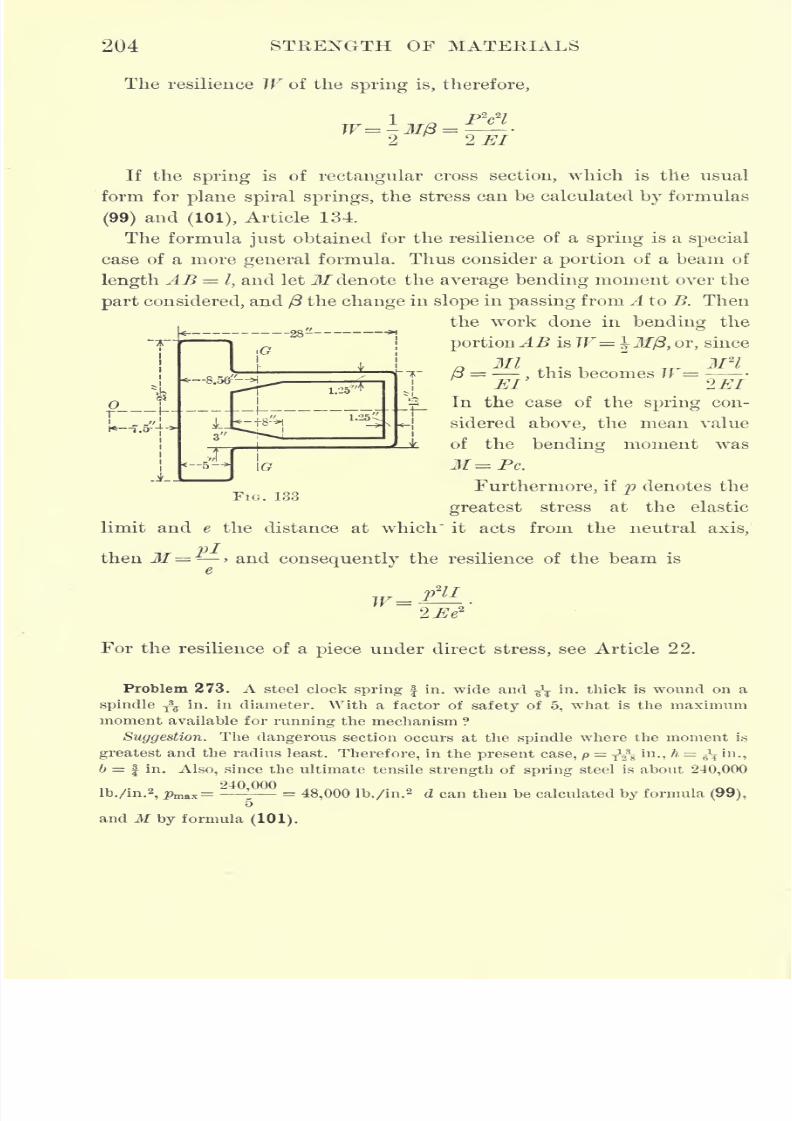
7/30/2019 Textbook on Streng 00 Slo Crich
http://slidepdf.com/reader/full/textbook-on-streng-00-slo-crich 246/433
204 STRENGTH OF MATERIALS
The resilience W of the spring is, therefore,
If the spring is of rectangular cross section, which is the usual
form for plane spiral springs, the stress can be calculated by formulas
(99) and(101), Article 134.
The formula just obtained for the resilience of a spring is a special
case of a more general formula. Thus consider a portion of a beam of
length AB = I, and letM denote the average bending moment over the
part considered, and (3 the change in slope in passing from A to B. Then
the work done in bending the
portionAB isW= \M(3, or, since
Ml ,, . M2l
p = ,this becomes W =
El 2El
\_In the case of the spring con-
sidered above, the mean value
of the bending moment was
M=Pc.
Furthermore, if p denotes the
greatest stress at the elastic
limit and e the distance at which" it acts from the neutral axis,
then M= > and consequently the resilience of the beam is
r~Lt
FIG. 133
For the resilience of a piece under direct stress, see Article 22.
Problem 273. A steel clock spring | in. wide and ^ in. thick is wound on a
spindle T3
^ in. in diameter. With a factor of safety of 5, what is the maximum
moment available for running the mechanism ?
Suggestion. The dangerous section occurs at the spindle where the moment is
greatest and the radius least. Therefore, in the present case, p=
TV5 in., h = g\ in.,
b = | in. Also, since the ultimate tensile strength of spring steel is about 240,000
lb./in.2, pm&x=24
'00
= 48,000 lb./in.2 d can then be calculated by formula (99),
5
and M by formula (101).
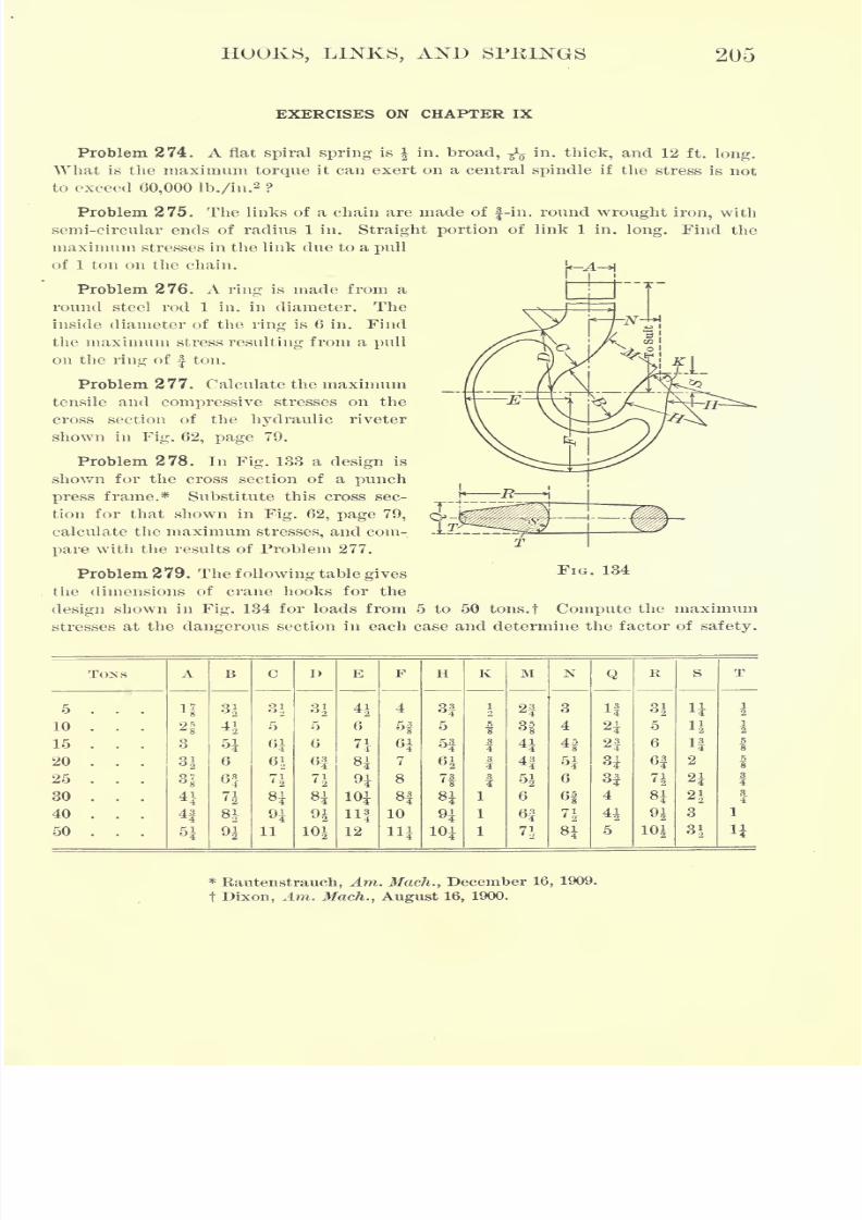
7/30/2019 Textbook on Streng 00 Slo Crich
http://slidepdf.com/reader/full/textbook-on-streng-00-slo-crich 247/433
HOOKS, LINKS, AND SPKINGS 205
EXERCISES ON CHAPTER IX
Problem274.
Aflat
spiral springis in.
broad, -^in.
thick,and 12 ft.
long.What is the maximum torque it can exert on a central spindle if the stress is not
to exceed 60,000 lb./in.2?
Problem 275. The links of a chain are made of f-in. round wrought iron, with
semi-circular ends of radius 1 in. Straight portion of link 1 in. long. Find the
maximum stresses in the link due to a pull
of 1 ton on the chain.
Problem 276. A ring is made from a
round steel rod 1 in. in diameter. The
inside diameter of the ring is 6 in. Find
the maximum stress resulting from a pull
on the ring of f ton.
Problem 277. Calculate the maximum
tensile and compressive stresses on the
cross section of the hydraulic riveter
shown in Fig. 62, page 79.
Problem 278. In Fig. 133 a design is
shown for the cross section of a punch
press frame.* Substitute this cross sec-
tion for that shown in Fig. 62, page 79,
calculate the maximum stresses, and com-
pare with the results of Problem 277.
Problem 279. The following table gives
the dimensions of crane hooks for the
design shown in Fig. 134 for loads from 5 to 50 tons.t Compute the maximum
stresses at the dangerous section in each case and determine the factor of safety.
T
FIG. 134
TONS
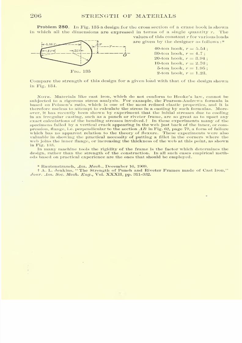
7/30/2019 Textbook on Streng 00 Slo Crich
http://slidepdf.com/reader/full/textbook-on-streng-00-slo-crich 248/433
206 STRENGTH OF MATERIALS
Problem 280. In Fig. 135 a design for the cross section of a crane hook is shown
in which all the dimensions are expressed in terms of a single quantity r. The
values of this constant r for various loads
"~^ are given by the designer as follows :*
, ^ ,, "I 40-ton hook, r=o.54;
30-ton hook, r = 4.7;
20-ton hook, r = 3.94;
10-ton hook, r = 2.76;
5-ton hook, r = 1.95;
2-ton hook, r = 1.23.
Compare the strength of this design for a given load with that of the design shown
in Fig. 134.
NOTE. Materials like cast iron, which do not conform to Hooke's law, cannot be
subjected to a rigorous stress analysis. For example, the Pearson-Andrews formula is
based on Poisson's ratio, which is one of the most refined elastic properties, and it is
therefore useless to attempt to calculate the stress in a casting by such formulas. More-
over, it has recently been shown by experiment that the initial stresses due to cooling
in an irregular casting, such as a punch or riveter frame, are so great as to upset anyexact calculations of the bending stresses involved. t In these experiments many of the
specimens failed by a vertical crack appearing in the web just back of the inner, or com-
pression, flange, i.e. perpendicular to the section AB in Fig. 62, page 79, a form of failure
which has no apparent relation to the theory of flexure. These experiments were alsovaluable in showing the practical necessity of putting a fillet in the corners where the
web joins the inner flange, or increasing the thickness of the web at this point, as shown
in Fig. 133.
In many machine tools the rigidity of the frame is the factor which determines the
design, rather than the strength of the construction. In all such cases empirical meth-
ods based on practical experience are the ones that should be employed.
*Rautenstrauch, Am. Mach., December 16, 1909.
t A. L. Jenkins, "The Strength of Punch and Riveter Frames made of Cast Iron,"
Jour. Am. Soc. Mech. Eng., Vol. XXXII, pp. 311-332.
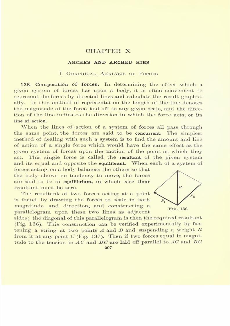
7/30/2019 Textbook on Streng 00 Slo Crich
http://slidepdf.com/reader/full/textbook-on-streng-00-slo-crich 249/433
CHAPTER X
ARCHES AND ARCHED RIBS
I. GRAPHICAL ANALYSIS OF FORCES
138. Composition of forces. In determining the effect which a
given system of forces has upon a body, it is often convenient to
represent the forces by directed lines and calculate the result graphic-
ally.In this method of representation the length of the line denotes
the magnitude of the force laid off to any given scale, and the direc-
tion of the line indicates the direction in which the force acts, or its
line of action.
When the lines of action of a system of forces all pass through
the same point, the forces are said to be concurrent. The simplest
method of dealing with such a system is to find the amount and line
of action of a single force which would have the same effect as the
given system of forces upon the motion of the point at which they
act. This single force is called the resultant of the given system
and its equal and opposite the equilibrant. When each of a system of
forces acting on a body balances the others so that
the body shows no tendency to move, the forces
are said to be in equilibrium, in which case their
resultant must be zero.
The resultant of two forces acting at a point
is found by drawing the forces to scale in both
magnitude and direction, and constructing a
parallelogram upon these two lines as adjacent
sides;the diagonal of this parallelogram is then the required resultant
(Fig. 136). This construction can be verified experimentally by fas-
tening a string at two points A and B and suspending a weight R
from it at any point C (Fig. 137). Then if two forces equal in magni-
tude to the tension in AC and BC are laid off parallelto AC and BC
207
FIG. 136
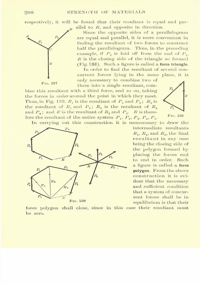
7/30/2019 Textbook on Streng 00 Slo Crich
http://slidepdf.com/reader/full/textbook-on-streng-00-slo-crich 250/433
208 STRENGTH OF MATERIALS
FIG. 137
respectively, it will be found that their resultant is equal and par-
allel to R, and opposite in direction.
Since the opposite sides of a parallelogram
are equal and parallel, it is more convenient in
finding the resultant of two forces to construct
half the parallelogram. Thus, in the preceding
example, if P2
is laid off from the end of Pv
R is the closing side of the triangle so formed
(Fig. 138). Such a figure is called a force triangle.
In order to find the resultant of several con-
current forces lying in the same plane, it is
only necessary to comhine two of
them into a single resultant, com-
bine this resultant with a third force, and so on, taking
the forces in order around the point in which they meet.
Thus, in Fig. 139, E lis the resultant of P
land P
2 ;R
zis
the resultant of Rland P
s ;R
sis the resultant of R
z
and P4 ;and R is the resultant of Rz and P5
. R is there-
fore the resultant of the entire system PI}P
2 ,P
3 ,P
4 ,P
5.
In carrying out this construction it is unnecessary to draw the
intermediate resultants
RV R2 , and P3 ,the final
resultant in any case
being the closing side of
the polygon formed by
placing the forces end
to end in order. Such
a figure is called a force
polygon. From the above
construction it is evi-
dent that the necessary
and sufficient condition
that a system of concur-
rent forces shall be in
equilibrium is that their
force polygon shall close, since in this case their resultant must
be zero.
FIG. 138
FlG ' 139
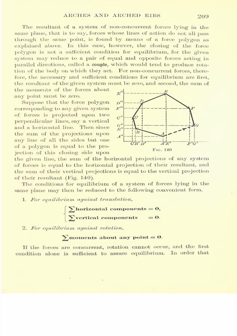
7/30/2019 Textbook on Streng 00 Slo Crich
http://slidepdf.com/reader/full/textbook-on-streng-00-slo-crich 251/433
ARCHES AND ARCHED RIBS 209
The resultant of a system of non-concurrent forces lying in the
same plane, that is to say, forces whose lines of action do not all pass
through the same point, is found by means of a force polygon as
explained above. In this case, however, the closing of the force
polygon is not a sufficient condition for equilibrium, for the given
system may reduce to a pair of equal and opposite forces acting in
parallel directions, called a couple, which would tend to produce rota-
tion of the body on which they act. For non-concurrent forces, there-
fore, the necessary and sufficient conditions for equilibrium are first,
the resultant of the given system must be zero, and second, the sum of
the moments of the forces about
any point must be zero.
Suppose that the force polygon
corresponding to any given system
of forces is projected upon two
perpendicular lines, say a vertical
and a horizontal line. Then since
the sum of the projections upon
any line of all the sides but one
D
F "
c"lc
1)
C'B'D' A'E'
FIG. 140
F'G'of a polygon is equal to the pro-
jection of this closing side upon
the given line, the sum of the horizontal projections of any system
of forces is equal to the horizontal projection of their resultant, and
the sum of their vertical projections is equal to the vertical projection
of their resultant (Fig. 140).
The conditions for equilibrium of a system of forces lying in the
same plane may then be reduced to the following convenient form.
1. For equilibrium against translation,
I ^yhorizontal components = O,
I
Vvertical components =O.
2. For equilibrium against rotation,
Vmoments about any point = O.
If the forces are concurrent, rotation cannot occur, and the first
condition alone is sufficient to assure equilibrium.In order that
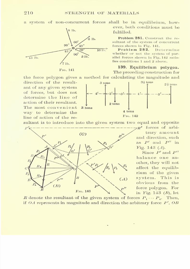
7/30/2019 Textbook on Streng 00 Slo Crich
http://slidepdf.com/reader/full/textbook-on-streng-00-slo-crich 252/433
210 STRENGTH OF MATERIALS
a system of non-concurrent forces shall be in equilibrium, how-
ever, both conditions must be
fulfilled.
6 lb.Problem 281. Construct the re-
sultant of the system of concurrent
forces shown in Fig. 141.
Problem 282. Determine
whether or not the system of par-
allel forces shown in Fig. 142 satis-
fies conditions 1 and 2 above.
139. Equilibrium polygon.
The preceding construction for
the force polygon gives a method for calculating the magnitude and
FIG. 141
3 tons
-4-'
2 tons
3^ tons
2 1 tons
4 tons
FIG. 142
direction of the result-
ant of any given system
of forces, but does not
determine the line of
action of their resultant.
The most convenient 3-tons
way to determine the
line of action of the re-
sultant is to introduce into the given system two equal and opposite1
forces of arbi-
trary amount
and direction, such
as P' and P" in
Fig. 143 (A).
Since Pf and P"
balance one an-
other, they will not
affect the equilib-
rium of the given
system. This is
obvious from the
force polygon. For
in Fig. 143 (B),let
R denote the resultant of the given system of forces Pl
P4
. Then,
if A represents in magnitude and direction the arbitrary force P', OB
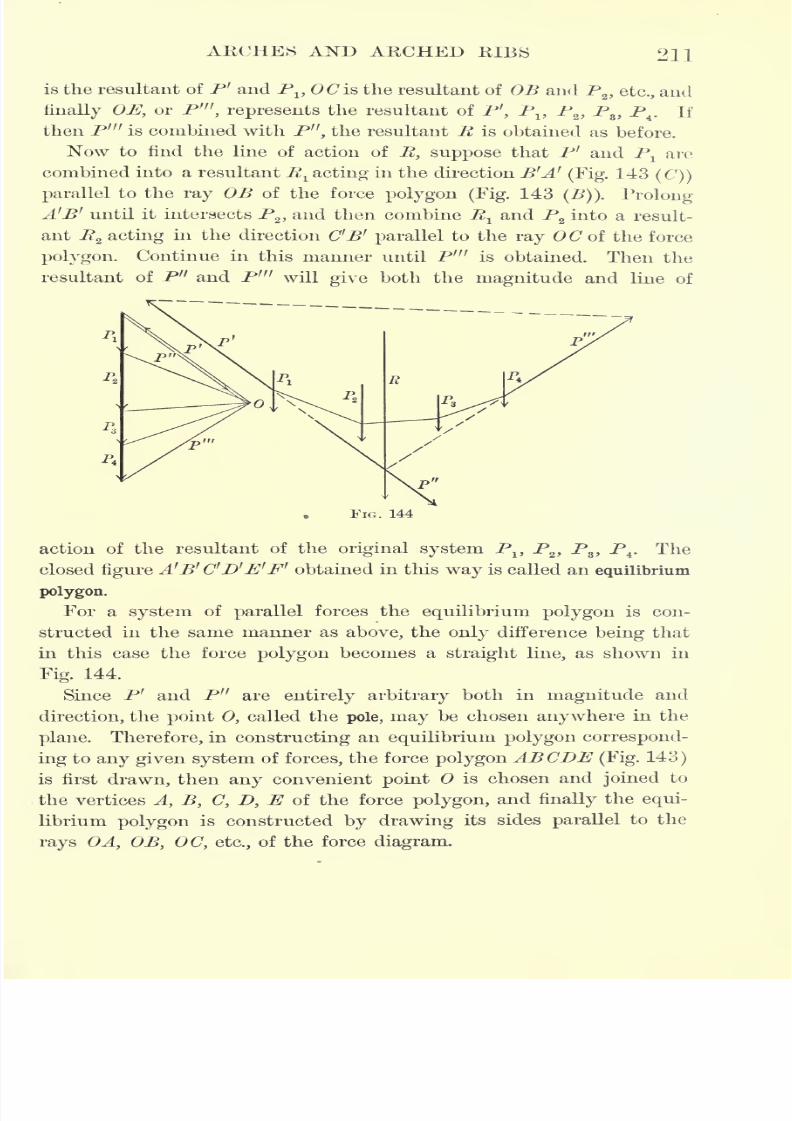
7/30/2019 Textbook on Streng 00 Slo Crich
http://slidepdf.com/reader/full/textbook-on-streng-00-slo-crich 253/433
ARCHES AND ARCHED RIBS 211
is the resultant of P' and P1?OCis the resultant of OB and P
2 , etc., and
finally OE, or P'", represents the resultant of P 1
',P
x ,P
2 ,P
8 ,P
4. If
then P'" is combined with P", the resultant JK is obtained as before.
Now to find the line of action of R, suppose that P' and Plare
combined into a resultant R^ acting in the direction B'A'(Fig. 143
(C))
parallel to the ray OB of the force polygon (Fig. 143(B)). Prolong
A'B' until it intersects P2 ,and then combine R^ and P
2into a result-
ant Rz acting in the direction C'B' parallel to the ray OC of the force
polygon. Continue in this manner until P'" is obtained. Then the
resultant of P" and P'n will give both the magnitude and line of
FIG. 144
action of the resultant of the original system P1?P
2 ,P
8 ,P
4. The
closed figure A'B' C'D'E'F' obtained in this way is called an equilibrium
polygon.
For a system of parallel forces the equilibrium polygon is con-
structed in the same manner as above, the only difference being that
in this case the force polygon becomes a straight line, as shown in
Fig. 144.
Since P' and P" are entirely arbitrary both in magnitude and
direction, the point 0, called the pole, may be chosen anywhere in the
plane. Therefore, in constructing an equilibrium polygon correspond-
ing to any given system of forces, the force polygon ABODE (Fig. 143)
is first drawn, then any convenient point is chosen and joined to
the vertices A, B, C, D, E of the force polygon, and finally the equi-
librium polygon is constructed by drawing its sides parallel to the
rays OA} OB, OC, etc., of the force diagram.
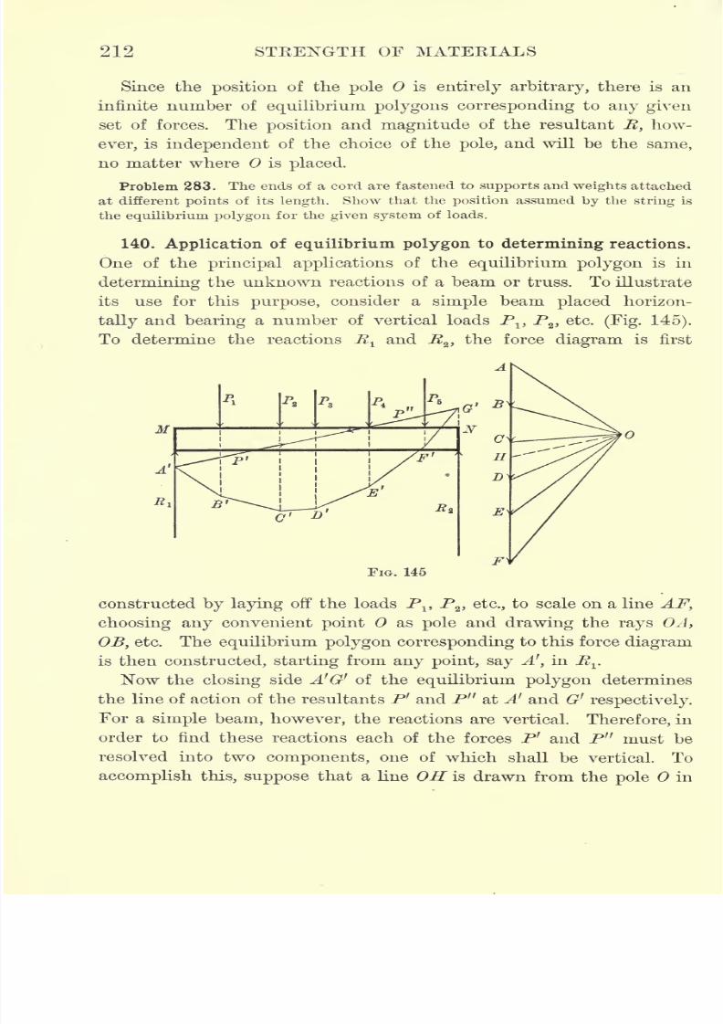
7/30/2019 Textbook on Streng 00 Slo Crich
http://slidepdf.com/reader/full/textbook-on-streng-00-slo-crich 254/433
212 STEENGTH OF MATEEIALS
Since the position of the pole is entirely arbitrary, there is an
infinite number of equilibrium polygons corresponding to any given
set of forces. Theposition
andmagnitude
of the resultant R, how-
ever, is independent of the choice of the pole, and will be the same,
no matter where is placed.
Problem 283. The ends of a cord are fastened to supports and weights attached
at different points of its length. Show that the position assumed by the string is
the equilibrium polygon for the given system of loads.
140. Application of equilibrium polygon to determining reactions.
One of the principal applications of the equilibrium polygon is in
determining the unknown reactions of a beam or truss. To illustrate
its use for this purpose, consider a simple beam placed horizon-
tally and bearing a number of vertical loads PltP
2 ,etc. (Fig. 145).
To determine the reactions E^ and Rz ,
the force diagram is first
FIG. 145
constructed by laying off the loads PltP
2 , etc., to scale on a line AF,
choosing any convenient point as pole and drawing the rays OA,
OB, etc. The equilibrium polygon corresponding to this force diagram
is thenconstructed, starting
fromany point, say
A 1
,in R
rNow the closing side A'G' of the equilibrium polygon determines
the line of action of the resultants P' and P" at Ar and G r
respectively.
For a simple beam, however, the reactions are vertical. Therefore, in
order to find these reactions each of the forces P' and P' f must be
resolved into two components, one of which shall be vertical. To
accomplish this, suppose that a line OH is drawn from the pole in
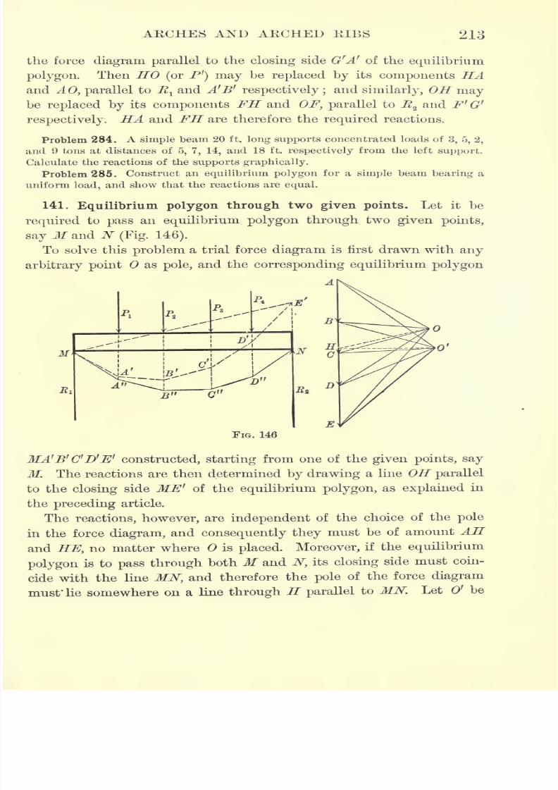
7/30/2019 Textbook on Streng 00 Slo Crich
http://slidepdf.com/reader/full/textbook-on-streng-00-slo-crich 255/433
AKCHES AND ARCHED EIBS 213
the force diagram parallel to the closing side GrA' of the equilibrium
polygon. Then HO (or P') may be replaced by its components HAand AO, parallel to E
1and A'B1
respectively ;and similarly, OH may
be replaced by its components FH and OF, parallel to jft2 and F' G'
respectively. HA and FH are therefore the required reactions.
Problem 284. A simple beam 20 ft. long supports concentrated loads of 3, 5, 2,
and 9 tons at distances of 5, 7, 14, and 18 ft. respectively from the left support.
Calculate the reactions of the supports graphically.
Problem 285. Construct an equilibrium polygon for a simple beam bearing a
uniform load, and show that the reactions are equal.
141. Equilibrium polygon through two given points. Let it be
required to pass an equilibrium polygon through two given points,
say M and N (Fig. 146).
To solve this problem a trial force diagram is first drawn with any
arbitrary point as pole, and the corresponding equilibrium polygon
FIG. 146
MA'B'C'D'E' constructed, starting from one of the given points, say
M. The reactions are then determined by drawing a line OH parallel
to the closing side ME' of the equilibrium polygon, as explained in
the preceding article.
The reactions, however, are independent of the choice of the pole
in the force diagram, and consequently they must be of amount AH
and HE, no matter where is placed. Moreover, if the equilibrium
polygon is to pass through both M and N, its closing side must coin-
cide with the line MNtand therefore the pole of the force diagram
must* He somewhere on a line through H parallel to MN. Let O1 be
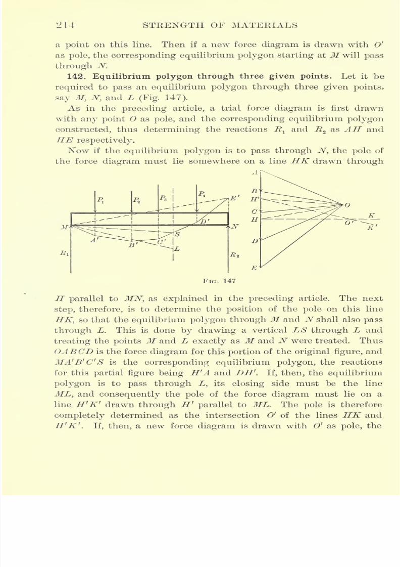
7/30/2019 Textbook on Streng 00 Slo Crich
http://slidepdf.com/reader/full/textbook-on-streng-00-slo-crich 256/433
214 STRENGTH OF MATERIALS
a point on this line. Then if a new force diagram is drawn with 0'
as pole, the corresponding equilibrium polygon starting at M will pass
through N.
142. Equilibrium polygon through three given points. Let it be
required to pass an equilibrium polygon through three given points,
say M, N, and L (Fig. 147).
As in the preceding article, a trial force diagram is first drawn
with any point as pole, and the corresponding equilibrium polygon
constructed, thus determining the reactions R1and R
2as AH and
HE respectively.
Now if the equilibrium polygon is to pass through N, the pole of
the force diagram must lie somewhere on a line HK drawn through
K
1)
FIG. 147
H parallel to MN, as explained in the preceding article. The next
step, therefore, is to determine the position of the pole on this line
HK, so that the equilibrium polygon through M and N shall also pass
through L. This is done by drawing a vertical LS through L and
treating the points M and L exactly as M and N were treated. Thus
GABCD is the force diagram for this portion of the original figure, and
MA'B'C'S is the corresponding equilibrium polygon, the reactions
for this partial figure being H'A and DH'. If, then, the equilibrium
polygon is to pass through L, its closing side must be the line
ML, and consequently the pole of the force diagram must lie on a
line H'K' drawn through H' parallel to ML. The pole is therefore
completely determined as the intersection 0' of the lines HK and
H'K' . If, then, a new force diagram is drawn with 0' as pole, the
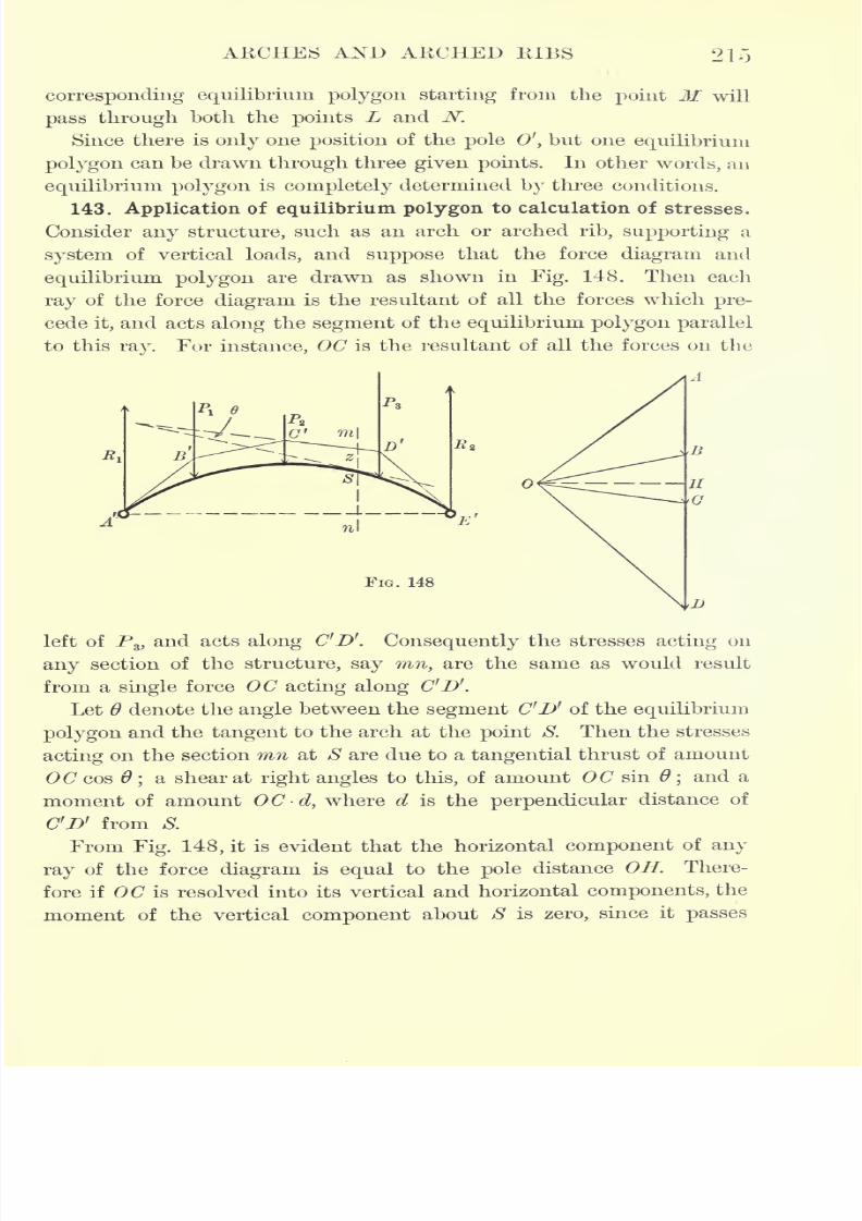
7/30/2019 Textbook on Streng 00 Slo Crich
http://slidepdf.com/reader/full/textbook-on-streng-00-slo-crich 257/433
AKCHES AND AKCHED KIBS
corresponding equilibrium polygon starting from the point M will
pass through both the points L and N.
Since there is only one position of the pole 0', but one equilibrium
polygon can be drawn through three given points. In other words, an
equilibrium polygon is completely determined by three conditions.
143. Application of equilibrium polygon to calculation of stresses.
Consider any structure, such as an arch or arched rib, supporting a
system of vertical loads, and suppose that the force diagram and
equilibrium polygon are drawn as shown in Fig. 148. Then each
ray of the force diagram is the resultant of all the forces which pre-
cede it, and acts along the segment of the equilibrium polygon parallel
to this ray. For instance, OC is the resultant of all the forces on the
FIG. 148
D
left of P3 , and acts along C'D'. Consequently the stresses acting on
any section of the structure, say mn, are the same as would result
from a single force OC acting along C'D'.
Let 6 denote the angle between the segment C'D' of the equilibrium
polygon and the tangent to the arch at the point S. Then the stresses
acting on the section mn at S are due to a tangential thrust of amount
OC cos;a shear at right angles to this, of amount OC sin
;and a
moment of amount OC-d, where d is the perpendicular distance of
C'D' from S.
From Fig. 148, it is evident that the horizontal component of any
ray of the force diagram is equal to the pole distance OH. There-
fore if 0(7 is resolved into its vertical and horizontal components, the
moment of the vertical component about S is zero, since it passes
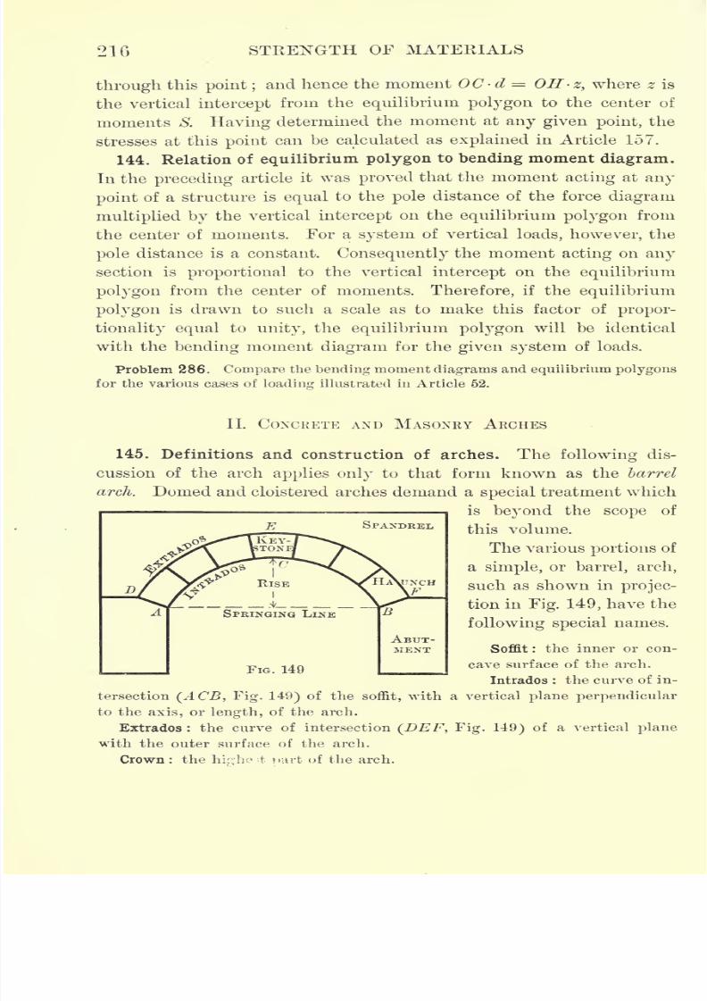
7/30/2019 Textbook on Streng 00 Slo Crich
http://slidepdf.com/reader/full/textbook-on-streng-00-slo-crich 258/433
216 STRENGTH OF MATERIALS
through this point ;and hence the moment OC d = OH- z, where z is
the vertical intercept from the equilibrium polygon to the center of
moments S.
Havingdetermined the moment at
any givenpoint, the
stresses at this point can be calculated as explained in Article 157.
144. Relation of equilibrium polygon to bending moment diagram.
In the preceding article it was proved that the moment acting at any
point of a structure is equal to the pole distance of the force diagram
multiplied by the vertical intercept on the equilibrium polygon from
the center of moments. For a system of vertical loads, however, the
poledistance is a constant.
Consequentlythe moment
actingon
anysection is proportional to the vertical intercept on the equilibrium
polygon from the center of moments. Therefore, if the equilibrium
polygon is drawn to such a scale as to make this factor of propor-
tionality equal to unity, the equilibrium polygon will be identical
with the bending moment diagram for the given system of loads.
Problem 286. Compare the bending moment diagrams and equilibrium polygons
for the various cases of loading illustrated in Article 62.
II. CONCRETE AND MASONRY ARCHES
145. Definitions and construction of arches. The following dis-
cussion of the arch applies only to that form known as the barrel
arch. Domed and cloistered arches demand a special treatment which
is beyond the scope of
this volume.
The various portions of
a simple, or barrel, arch,
such as shown in projec-
tion in Fig. 149, have the
following special names.
Soffit:
the inneror
con-cave surface of the arch.
Intrados : the curve of in-
tersection (ACB, Fig. 149) of the soffit, with a vertical plane perpendicular
to the axis, or length, of the arch.
Extrados : the curve of intersection (DEF, Fig. 149) of a vertical plane
with the outer surface of the arch.
Crown : the hk;-hc 't wrt of the arch.
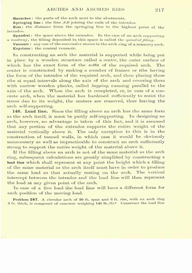
7/30/2019 Textbook on Streng 00 Slo Crich
http://slidepdf.com/reader/full/textbook-on-streng-00-slo-crich 259/433
ARCHES AND AECHED BIBS 217
Haunches : the parts of the arch next to the abutments.
Springing line : the line AB joining the ends of the intrados.
Rise : the distance from the springing line to the highest point of the
intrados.
Spandrel : the space above the extrados. In the case of an arch supporting
a roadway, the filling deposited in this space is called the spandrel Jilting.
Voussoir : any one of the successive stones in the arch ring of a masonry arch.
Keystone : the central voussoir.
In constructing an arch the material is supported while being put
in place by a wooden structure called a center, the outer surface of
which has the exact form of the soffit of the required arch. The
center is constructed by making a number of frames or ribs having
the form of the intrados of the required arch, and then placing these
ribs at equal intervals along the axis of the arch and covering them
with narrow wooden planks, called lagging, running parallel to the
axis of the arch. When the arch is completed, or, in case of a con-
crete arch, when the material has hardened sufficiently to resist the
stress due to its weight, the centers are removed, thus leaving the
arch self-supporting.
146. Load line. Since the filling above an arch has the same form
as the arch itself, it must be partly self-supporting. In designing an
arch, however, no advantage is taken of this fact, and it is assumed
that any portion of the extrados supports the entire weight of the
material vertically above it. The only exception to this is in the
construction of tunnel walls, in which case it would be obviously
unnecessary as well as impracticable to construct an arch sufficiently
strong to support the entire weight of the material above it.
If the filling above an arch is not of the same material as the arch
ring, subsequent calculations are greatly simplified by constructing a
load line which shall represent at any point the height which a filling
of the same material as the arch itself must have in order to produce
the same load as that actually resting on the arch. The vertical
intercept between the intrados and the load line will then represent
the load at any given point of the arch.
In case of a live load the load line will have a different form for
each position of the moving load.
Problem 287. A circular arch of 20 ft. span and 6 ft. rise, with an arch ring
3 ft. thick, is composed of concrete weighing 140 lb./ft.3 Construct the load line
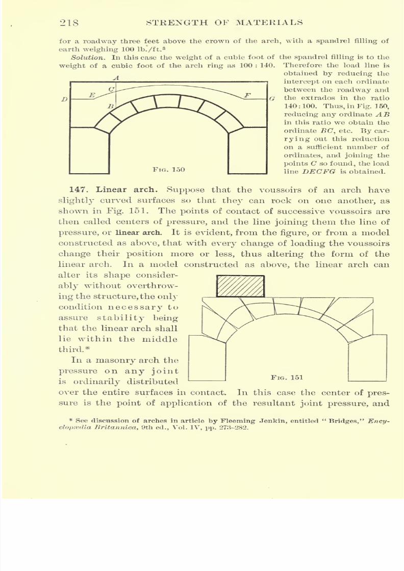
7/30/2019 Textbook on Streng 00 Slo Crich
http://slidepdf.com/reader/full/textbook-on-streng-00-slo-crich 260/433
218 STRENGTH OF MATERIALS
for a roadway three feet above the crown of the arch, with a spandrel filling of
earth weighing 100 lb.'/ft.3
Solution. In this case the weight of a cubic foot of the spandrel filling is to the
weight of a cubic foot of the arch ring as 100 : 140. Therefore the load line is
obtained by reducing the
intercept on each ordinate
between the roadway and
the extrados in the ratio
140:100. Thus, in Fig. 150,
reducing any ordinate ABin this ratio we obtain the
ordinate EC, etc. By car-
rying out this reduction
on a sufficient number of
ordinates, and joining the
points C so found, the load
line DJECFG is obtained.
147. Linear arch. Suppose that the voussoirs of an arch have
slightly curved surfaces so that they can rock on one another, as
shown in Fig. 151. The points of contact of successive voussoirs are
then called centers of pressure, and the line joining them the line of
pressure, or linear arch. It is evident, from the figure, or from a model
constructed as above, that with every change of loading the voussoirs
change their position more or less, thus altering the form of the
linear arch. In a model constructed as above, the linear arch can
alter its shape consider-
ably without overthrow-
ing the structure, the only
condition necessary to
assure stability being
that the linear arch shall
lie within the middle
third.*
In a masonry arch the
pressure on any jointis ordinarily distributed
over the entire surfaces in contact. In this case the center of pres-
sure is the point of application of the resultant joint pressure, and
* See discussion of arches in article by Fleeming Jenkin, entitled"Bridges," Ency-
clopedia Britannica, 9th ed., Vol. IV, pp. 273-282.
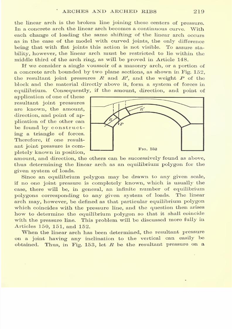
7/30/2019 Textbook on Streng 00 Slo Crich
http://slidepdf.com/reader/full/textbook-on-streng-00-slo-crich 261/433
'
AECHES AND AECHED KIBS 219
the linear arch is the broken line joining these centers of pressure.
In a concrete arch the linear arch becomes a continuous curve. With
each change of loading the same shifting of the linear arch occurs
as in the case of the model with curved joints, the only difference
being that with flat joints this action is not visible. To assure sta-
bility, however, the linear arch must be restricted to lie within the
middle third of the arch ring, as will be proved in Article 148.
If we consider a single voussoir of a masonry arch, or a portion of
a concrete arch bounded by two plane sections, as shown in Fig. 152,
the resultant joint pressures R and R', and the weight P of the
block and the material directly above it, form a system of forces in
equilibrium. Consequently, if the amount, direction, and point of
application of one of these
resultant joint pressures
are known, the amount,
direction, and point of ap-
plication of the other can
be found by construct-
ing a triangle of forces.
Therefore, if one result-
ant joint pressure is com-
pletely known in position,
amount, and direction, the others can be successively found as above,
thus determining the linear arch as an equilibrium polygon for the
given system of loads.
Since an equilibrium polygon may be drawn to any given scale,
if no one joint pressure is completely known, which is usually the
case, there will be, in general, an infinite number of equilibrium
polygons corresponding to any given system of loads. The linear
arch may, however, be defined as that particular equilibrium polygon
which coincides with the pressure line, and the question then arises
how to determine the equilibrium polygon so that it shall coincide
with the pressure line. This problem will be discussed more fully in
Articles 150, 151, and 152.
When the linear arch has been determined, the resultant pressure
on a joint having any inclination to the vertical can easily be
obtained. Thus, in Fig. 153, let R be the resultant pressure on a
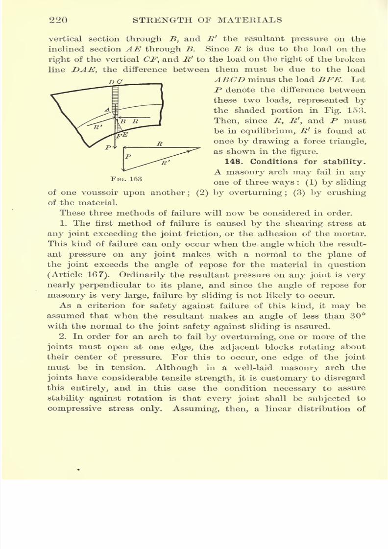
7/30/2019 Textbook on Streng 00 Slo Crich
http://slidepdf.com/reader/full/textbook-on-streng-00-slo-crich 262/433
220 STRENGTH OF MATERIALS
DC
R'
FIG. 153
vertical section through B, and R' the resultant pressure on the
inclined section AE through B. Since R is due to the load on the
right of the vertical CF, and R 1
to the load 011 the right of the broken
line DAE, the difference between them must be due to the load
ABCD minus the load BFE. Let
P denote the difference between
these two loads, represented by
the shaded portion in Fig. 153.
Then, since R, RJ
,and P must
be in equilibrium, R' is found at
once by drawing a force triangle,
as shown in the figure.
148. Conditions for stability.
A masonry arch may fail in any
one of three ways :(1) by sliding
of one voussoir upon another; (2) by overturning; (3) by crushing
of the material.
These three methods of failure will now be considered in order.
1. The first method of failure is caused by the shearing stress at
any joint exceeding the joint friction, or the adhesion of the mortar.
This kind of failure can only occur when the angle which the result-
ant pressure on any joint makes with a normal to the plane of
the joint exceeds the angle of repose for the material in question
(Article 167). Ordinarily the resultant pressure on any joint is very
nearly perpendicular to its plane, and since the angle of repose for
masonry is very large, failure by sliding is not likely to occur.
As a criterion for safety against failure of this kind, it may be
assumed that when the resultant makes an angle of less than 30
with the normal to the joint safety against sliding is assured.
2. In order for an arch to fail by overturning, one or more of the
joints must open at one edge, the adjacent blocks rotating about
their center of pressure. For this to occur, one edge of the joint
must be in tension. Although in a well-laid masonry arch the
joints have considerable tensile strength, it is customary to disregard
this entirely, and in this case the condition necessary to assure
stability against rotation is that every joint shall be subjected to
compressive stress only. Assuming, then, a linear distribution of
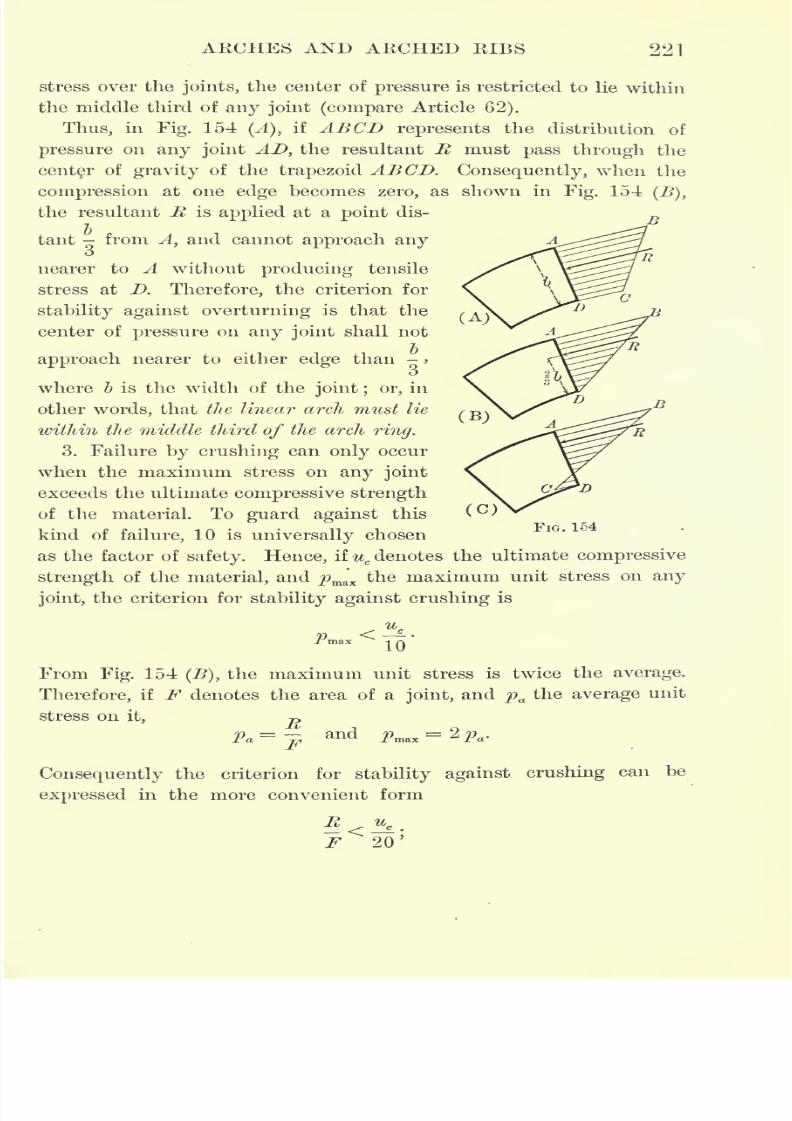
7/30/2019 Textbook on Streng 00 Slo Crich
http://slidepdf.com/reader/full/textbook-on-streng-00-slo-crich 263/433
ARCHES AND ARCHED RIBS 221
stress over the joints, the center of pressure is restricted to lie within
the middle third of any joint (compare Article 62).
Thus, in Fig. 154 (A), if ABCD represents the distribution of
pressure on any joint AD, the resultant R must pass through the
center of gravity of the trapezoid ABCD. Consequently, when the
compression at one edge becomes zero, as shown in Fig. 154(B),
the resultant R is applied at a point dis-
tant from Ayand cannot approach any
o
nearer to A without producing tensile
stress at D. Therefore, the criterion for
stability against overturning is that the
center of pressure on any joint shall not
approach nearer to either edge than ->
o
where b is the width of the joint ; or, in
other words, that the linear arch must lie
within the middle third
ofthe arch
ring.3. Failure by crushing can only occur
when the maximum stress on any joint
exceeds the ultimate compressive strength
of the material. To guard against this
kind of failure, 10 is universally chosen
as the factor of safety. Hence, if ucdenotes the ultimate compressive
strengthof the
material,and
j9ma
'
x
the maximum unit stress on
anyjoint, the criterion for stability against crushing is
FIG. 154
From Fig. 154 (B), the maximum unit stress is twice the average.
Therefore, if F denotes the area of a joint,and pa
the average unit
stress on it, P
Consequently the criterion for stability against crushing can be
expressed in the more convenient form
F 20'
7/30/2019 Textbook on Streng 00 Slo Crich
http://slidepdf.com/reader/full/textbook-on-streng-00-slo-crich 264/433
222 STRENGTH OF MATERIALS
that is to say, the average unit stress on any joint must not exceed
one twentieth of the ultimate compressive strength of the material.
The above conditions for stability can be applied equally as well
to a concrete arch by considering the stress on any plane section of
the arch ring.
149. Maximum compressive stress. Let R denote the resultant
pressure on any joint,b the width of the joint, F its area, and c the
distance of the center of pressure from the center of gravity of the
joint. Then, under the assumption of a linear distribution of stress,
the stress on the joint is due to a uniformly distributed thrust of
T>
amount per unit of area, and a moment M of amount M= Re.
Therefore the unit stress p at any point is given by the formula
R .Mep = ,r F I
where e is the distance of the extreme fiber from the center of gravity,
and / is the momentof inertia of
the crosssection.
For a section of unit length, F = b-l =b, I = > and e = -.
I u
Therefore, substituting these values, the formula for maximum or
minimum stress becomes
R,
6 RePmax
= '
min
For e = - the minimum stress is zero, and if c
>
- it becomesnega-6 .6
tive, thus restricting the center of pressure to lie within the middle
third of the cross section if tensile stress is prohibited (compare
Article 62 and Article 148, 2).
Combining this result with that of the preceding article, the maxi-
mum stress calculated by the formula
_R 6 Re
must not exceed -> where u
cis the ultimate compressive strength
of the material.
150. Location of the linear arch : Moseley's theory. In order to
obtain a starting point for the construction of the linear arch, it is
necessary to know the amount, direction, and point of application
7/30/2019 Textbook on Streng 00 Slo Crich
http://slidepdf.com/reader/full/textbook-on-streng-00-slo-crich 265/433
AKCHES AND AKCHED KIBS 223
of one joint pressure, as explained in Article 147; or, in general, it
is necessary to have given three conditions which the equilibrium
polygon must satisfy, such, for instance, as three points through
which it is required to pass. Since it is impossible to determine these
three unknowns by the principles of mechanics, the theory of the
arch has long been a subject of controversy among engineers and
mathematicians.
Among the various theories of the arch which have been proposed
from time to time, the first and most important of the older theories
is called the principle of least resistance. This theory was introduced by
the English engineer, Moseley, in 1837, and later became famous on the
Continent through a German translation of Moseley's work by Scheffler.
In building an arch the material is assembled upon a wooden frame-
work called a center;when the arch is complete this center is removed
and the arch becomes self-supporting, as explained in Article 145.
Now suppose that instead of removing the center suddenly, it is
gradually lowered so that the arch becomes self-supporting by degrees.
In this case the horizontal pressure or thrust at the crown gradually
increases until the center has been completely removed, when it has
its least possible value. This hypothesis of least crown thrust con-
sistent with stability is Moseley's principle of least resistance.
In constructing an equilibrium polygon the horizontal force, or
pole distance, is least when the height of the polygon is a maximum.
Therefore, in order to apply the principle of least resistance, the equi-
librium polygon must pass through the highest point of the extrados
at the crown and the lowest points of the intrados at the abutments.
Since this would cause tensile stress at both the crown and abut-
ments, the criterion for stability against overturning makes it neces-
sary in applying the theory to move the center and ends of the
equilibrium polygon, or linear arch, until it falls within the middle
third of the arch ring. There is nothing in the principle of least
resistance, however, to warrant this change in the position of the
equilibrium polygon, and consequently the theory is inconsistent with
its application.
Culmann tried to overcome this objection to Moseley's theory by
considering the compressibility of the mortar between the joints.At
the points of greatest pressure the mortar will be compressed more
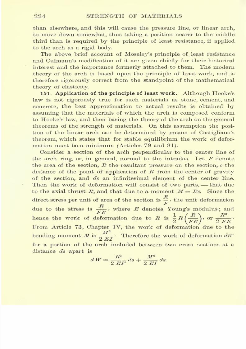
7/30/2019 Textbook on Streng 00 Slo Crich
http://slidepdf.com/reader/full/textbook-on-streng-00-slo-crich 266/433
224 STRENGTH OF MATERIALS
than elsewhere, and this will cause the pressure line, or linear arch,
to move down somewhat, thus taking a position nearer to the middle
third than is required by the principle of least resistance, if applied
to the arch as a rigid body.
The above brief account of Moseley's principle of least resistance
and Culmann's modification of it are given chiefly for their historical
interest and the importance formerly attached to them. The modem
theory of the arch is based upon the principle of least work, and is
therefore rigorously correct from the standpoint of the mathematical
theory of elasticity.
151. Application of the principle of least work. Although Hooke's
law is not rigorously true for such materials as stone, cement, and
concrete, the best approximation to actual results is obtained by
assuming that the materials of which the arch is composed conform
to Hooke's law, and then basing the theory of the arch on the general
theorems of the strength of materials. On this assumption the posi-
tion of the linear arch can be determined by means of Castigliano's
theorem, which states that for stable equilibrium the work of defor-
mation must be a minimum (Articles 79 and 81).
Consider a section of the arch perpendicular to the center line of
the arch ring, or, in general, normal to the intrados. Let F denote
the area of the section, R the resultant pressure on the section, c the
distance of the point of application of R from the center of gravity
of the section, and ds an infinitesimal element of the center line.
Then the work of deformation will consist of two parts, that due
to the axial thrust It, and that due to a moment M = Re. Since theT->
direct stress per unit of area of the section is > the unit deformation
Rdue to the stress is > where E denotes Young's modulus; and
FE -.
/ 7? \ 7?2
hence the work of deformation due to R is -R{ )>or
2 \FEI2 FE
From Article 73, Chapter IV, the work of deformation due to theM2
bending moment M is Therefore the work of deformation dW2 El
for a portion of the arch included between two cross sections at a
distance ds apart is
,T/r
. R2, M*
dW = - ds H ds.
2EF 2 El
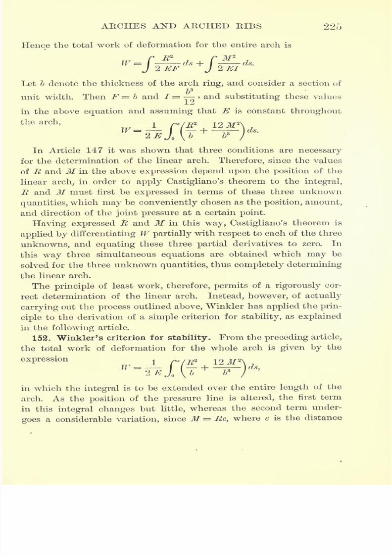
7/30/2019 Textbook on Streng 00 Slo Crich
http://slidepdf.com/reader/full/textbook-on-streng-00-slo-crich 267/433
ARCHES AND ARCHED RIBS 225
Hence the total work of deformation for the entire arch is
/R
2 C M2
2
EF
d +
J ^EI
d
Let b denote the thickness of the arch ring, and consider a section of
unit width. Then F = b and / = > and substituting these values
in the above equation and assuming that E is constant throughout
the arch, -.
W=
In Article 147 it was shown that three conditions are necessary
for the determination of the linear arch. Therefore, since the values
of R and M in the above expression depend upon the position of the
linear arch, in order to apply Castigliano's theorem to the integral,
R and M must first be expressed in terms of these three unknown
quantities, which may be conveniently chosen as the position, amount,
and direction of thejoint pressure
at a certainpoint.
Having expressed R and M in this way, Castigliano's theorem is
applied by differentiating W partially with respect to each of the three
unknowns, and equating these three partial derivatives to zero. In
this way three simultaneous equations are obtained which may be
solved for the three unknown quantities, thus completely determining
the linear arch.
The principleof least
work, therefore, permitsof a
rigorously
cor-
rect determination of the linear arch. Instead, however, of actually
carrying out the process outlined above, Winkler has applied the prin-
ciple to the derivation of a simple criterion for stability, as explained
in the following article.
152. Winkler's criterion for stability. From the preceding article,
the total work of deformation for the whole arch is given by the
expression-,
in which the integral is to be extended over the entire length of the
arch. As the position of the pressure line is altered, the first term
in this integral changes but little, whereas the second term under-
goes a considerable variation, since M = Re, where c is the distance
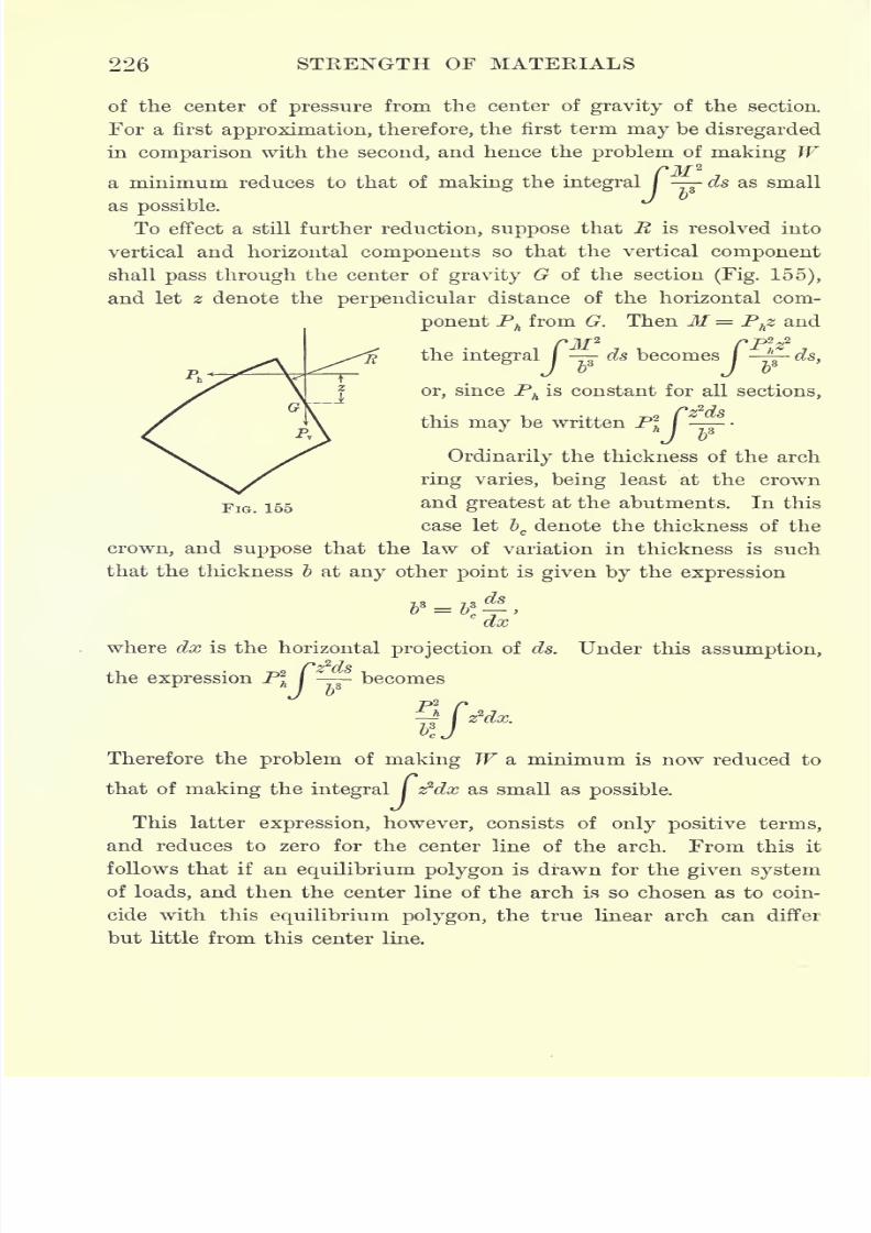
7/30/2019 Textbook on Streng 00 Slo Crich
http://slidepdf.com/reader/full/textbook-on-streng-00-slo-crich 268/433
226 STRENGTH OF MATERIALS
of the center of pressure from the center of gravity of the section.
For a first approximation, therefore, the first term may be disregarded
incomparison
with thesecond,
and hence theproblem
of
making W/M
2
ds as small
as
To effect a still further reduction, suppose that R is resolved into
vertical and horizontal components so that the vertical component
shall pass through the center of gravity G of the section (Fig. 155),
and let z denote the perpendicular distance of the horizontal com-
ponent Ph from G. Then M= Phz and
/jf
2rp~s?
ds becomes I ^- ds,b
or, since Phis constant for all sections,
this may be written P\ I -
Ordinarily the thickness of the arch
ring varies, being least at the crown
FlG 165and greatest at the abutments. In this
case let bcdenote the thickness of the
crown, and suppose that the law of variation in thickness is such
that the thickness I at any other point is given by the expression
c
~dx
where dx is the horizontal projection of ds. Under this assumption,
the expression P\ I - becomes
Therefore the problem of making W a minimum is now reduced to
that of making the integral / z*dx as small as possible.
This latter expression, however, consists of only positive terms,
and reduces to zero for the center line of the arch. From this it
follows that if an equilibrium polygon is drawn for the given system
of loads, and then the center line of the arch is so chosen as to coin-
cide with this equilibrium polygon, the true linear arch can differ
but little from this center line.
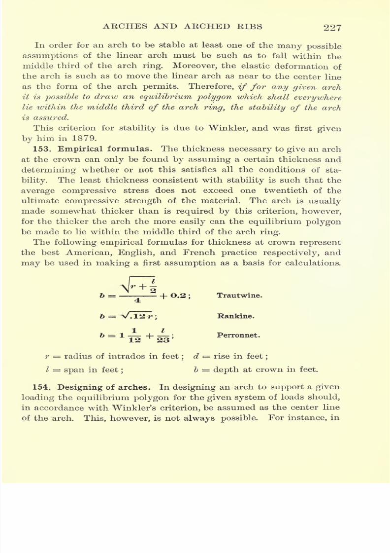
7/30/2019 Textbook on Streng 00 Slo Crich
http://slidepdf.com/reader/full/textbook-on-streng-00-slo-crich 269/433
AECHES AND ARCHED KIBS 227
In order for an arch to be stable at least one of the many possible
assumptions of the linear arch must be such as to fall within the
middle third of the arch ring. Moreover, the elastic deformation of
the arch is such as to move the linear arch as near to the center line
as the form of the arch permits. Therefore, if for any given arch
it is possible to draw an equilibrium polygon which shall everywhere
lie within the middle third of the archring, the stability of the arch
is assured.
This criterion for stability is due to Winkler, and was first given
by him in 1879.
153. Empirical formulas. The thickness necessary to give an arch
at the crown can only be found by assuming a certain thickness and
determining whether or not this satisfies all the conditions of sta-
bility. The least thickness consistent with stability is such that the
average compressive stress does not exceed one twentieth of the
ultimate compressive strength of the material. The arch is usually
made somewhat thicker than is requiredby
this criterion, however,
for the thicker the arch the more easily can the equilibrium polygon
be made to lie within the middle third of the arch ring.
The following empirical formulas for thickness at crown represent
the best American, English, and French practice respectively, and
may be used in making a first assumption as a basis for calculations.
Trautwine.
Rankine.
r = radius of intrados in feet;
d rise in feet;
/ = span in feet;
b = depth at crown in feet.
154. Designing of arches. In designing an arch to support a given
loading the equilibrium polygon for the given system of loads should,
in accordance with Winkler's criterion, be assumed as the center line
of the arch. This, however, is not always possible,For instance, in
7/30/2019 Textbook on Streng 00 Slo Crich
http://slidepdf.com/reader/full/textbook-on-streng-00-slo-crich 270/433
228 STRENGTH OF MATERIALS
the case of an arch intended to support a roadway, the level of which
is fixed, the loading depends to a large extent on the form of the
arch, and consequently the equilibrium polygon cannot be determined
until the form of the arch has been assumed.
In designing arches, therefore, the method usually followed is to
assume the form of the intrados of the required arch, and determine
its thickness at the crown by an empirical formula, such as those
given in the preceding article. Then, having draw^n the extrados and
load line, the surface between the intrados and the load line is
divided into any convenient number of parts by drawing verticals,
and the amount and position of the resultant weight of each part for
a section one foot wide is calculated. An equilibrium polygon for
this system of loads is then passed through the middle point of the
arch ring at crown and abutments by the method given in Article 142.
If this equilibrium polygon lies within the middle third of the arch
ring, the arch is assumed to be stable against overturning.
If the equilibrium polygonthrough
the middle points of the arch
ring at crown and abutments does not lie entirely within the mid-
dle third of the arch ring, these three points are shifted so as
to make it do so if possible. If no choice of the three points will
make the equilibrium polygon lie entirely within the middle third
of the arch ring, the design must be altered until this has been
accomplished.
The next step is to calculate the maximum unit jointpressure by
the formula given in Article 149, and apply the criterion for stability
against crushing given in Article 148. When these criteria have been
satisfied the design is assumed to be safe. If, however, there is a
considerable excess of strength, the design may be lightened and the
criteria reapplied.
Before the design can be considered complete it must also be
shown that the above criteria are satisfied for
every
form of
loadingto which the arch is likely to be subjected. In the case of an arch
designed to carry a heavy live load, such as that due to several
locomotives, it may be necessary to draw a number of load lines
corresponding to different positions of the load, and make a corre-
sponding number of determinations of the equilibrium polygon and
maximumjoint pressure.

7/30/2019 Textbook on Streng 00 Slo Crich
http://slidepdf.com/reader/full/textbook-on-streng-00-slo-crich 271/433
AKCHES AND AKCHED KIBS 229
The stability of the abutments still remains to be investigated, and
finally the bearing power of the soil on which these abutments rest.
Problem 288.
Design
a concrete arch to
spana stream 25 ft. in width and
sup-port a roadway 15 ft. above the level of the stream, if the spandrel filling is clay
weighing 120 lb./ft.3
;the maximum depth of frost is 3 ft. and the bearing power
of the soil at this depth is 4 tons /ft.2(see Article 158).
155. Stability of abutments. To determine the stability of the
abutments, the joint pressure at the haunch is combined with the
weight of the abutment into a single resultant, say R1
. Forstability
against overturning, the line of action of this resultant must strike
within the middle third of the base (Article 148, 2).
Eesolving the resultant R' into a horizontal component Rhand a
vertical component Rv)the maximum pressure on the soil is calcu-
lated by substituting this value of Rv
for R in the formula given in
Article 149. To prevent sinking of the abutments, this pressure must
not exceed the bearing power of the soil(see Article
166).
For stability against sliding, the shearing stress between the abut-
ment and the soil, due to the horizontal component Rhof the result-
ant R', must be less than the friction between the two; or, more
briefly, the angle which R f makes with the horizontal must be less
than the angle of repose (compare Article 172).
156. Oblique projection of arch. Suppose that an arch, its load line,
and its pressure line are drawn to any given scale, and then the whole
figure is projected upon an oblique plane by a system of parallel lines.
The projection of the pressure line on this oblique plane will then be
the true pressure line for the projected arch and its projected load line.
This principle can often be used to advantage, as, for example, in
comparing two arches of equal span but different rise. Its most
important application is in giving an accurate construction of the
pressure line for arches of long span and small rise. Thus, instead of
plotting such an arch to scale, its projection can be plotted ; or, in
other words, its span can be shortened any convenient amount. A
larger unit can then be used in plotting the vertical dimensions than
would otherwise be possible, and consequently the pressure line can
be drawn to any desired degree of accuracy.
Having constructed the pressure line in this way, the pressure on
any joint of the given arch can be found from the pressure on the
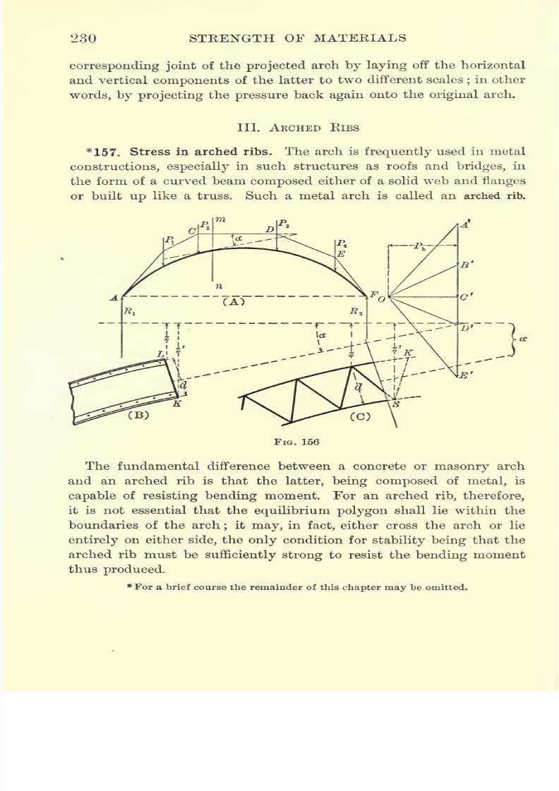
7/30/2019 Textbook on Streng 00 Slo Crich
http://slidepdf.com/reader/full/textbook-on-streng-00-slo-crich 272/433
230 STRENGTH OF MATERIALS
corresponding joint of the projected arch by laying off the horizontal
and vertical components of the latter to two different scales;in other
words, by projecting the pressure back again onto the original arch.
III. ARCHED RIBS
*157. Stress in arched ribs. The arch is frequently used in metal
constructions, especially in such structures as roofs and bridges, in
the form of a curved beam composed either of a solid web and flanges
or built up like a truss. Such a metal arch is called an arched rib.
FIG. 156
The fundamental difference between a concrete or masonry arch
and an arched rib is that the latter, being composed of metal, is
capable of resisting bending moment. For an arched rib, therefore,
it is not essential that theequilibrium polygon
shall lie within the
boundaries of the arch;
it may, in fact, either cross the arch or lie
entirely on either side, the only condition for stability being that the
arched rib must be sufficiently strong to resist the bending moment
thus produced.
*For a brief course the remainder of this chapter may be omitted.
7/30/2019 Textbook on Streng 00 Slo Crich
http://slidepdf.com/reader/full/textbook-on-streng-00-slo-crich 273/433
AKCHES AND AKCHED KIBS 231
When the equilibrium polygon has been drawn for the given system
of loads, the stress at any point of an arched rib can be calculated by
the method explained in Article 143. Thus, in Fig. 156(^t),
let AGFdenote the arched rib, Pv P2 ,
etc. the given loads, and ABCDEFthe
corresponding equilibrium polygon. Then the stress on any section
mn is due to a force acting in the direction CD, of amount equal to
the corresponding ray OCr
of the force diagram.
Consequently, if the rib is composed of a solid web and flanges,
as shown in Fig. 156 (B), the direct stress on the section is equal in
amount to the ray OCf
of the force diagram, the bending stress on
P z1
P zthe upper flange is ~ > the bending stress on the lower flange is -
,
Cu CL
and the shear normal to the rib is OC f
sin a, where a is the angle
between CD and the tangent to the rib at the section.
Similarly, for the trussed rib shown in Fig. 156 (C), by taking
moments about L and S the stresses in ItS and LK are found to be
P z P z'
f-and
7- respectively,while the normal
componentof the stress
a d
in LS is OC sin a.
Arched ribs are usually constructed in one of three different ways :
(1) hinged at the abutments and at the crown; (2) hinged at the
abutments and continuous throughout; (3)fixed at the abutments
and continuous throughout. The method of constructing the equilib-
rium polygon differs for each of these three methods of support, and
will be treated separately in what follows.
158. Three-hinged arched rib. When a member is free to turn
at any point the bending moment at that point is zero, and con-
sequently the equilibrium polygon, or bending moment diagram,
passes through the point. For a three-hinged arched rib, therefore,
the equilibrium polygon must pass through the centers of the
three hinges and is therefore completely determined, as explained in
Article 142.
159. Two-hinged arched rib. Consider an arched rib hinged at
the ends and continuous between these points.In this case the
equilibrium polygon must pass through the centers of both hinges,
but since there is no restriction on the vertical scale, this scale may
be anything whatever, depending on the choice of the pole in the
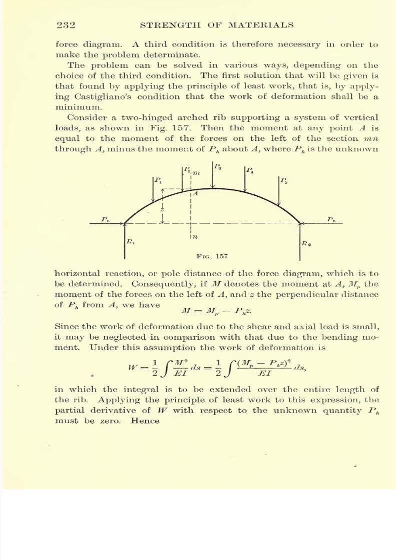
7/30/2019 Textbook on Streng 00 Slo Crich
http://slidepdf.com/reader/full/textbook-on-streng-00-slo-crich 274/433
232 STRENGTH OF MATERIALS
force diagram. A third condition is therefore necessary in order to
make the problem determinate.
The problem can be solved in various ways, depending on the
choice of the third condition. The first solution that will be given is
that found by applying the principle of least work, that is, by apply-
ing Castigliano's condition that the work of deformation shall be a
minimum.
Consider a two-hinged arched rib supporting a system of vertical
loads, as shown in Fig. 157. Then the moment at any point A is
equal to the moment of the forces on the left of the section mn
through A, minus the moment of Phabout A, where Ph
is the unknown
A
VFIG. 157
horizontal reaction, or pole distance of the force diagram, which is to
be determined. Consequently, if M denotes the moment at A,Mpthe
moment of the forces on the left of A, and z the perpendicular distance
of Phfrom A, we have
M= Mp- P
hz.
Since the work of deformation due to the shear and axial load is small,
it may be neglected in comparison with that due to the bending mo-
ment. Under this assumption the work of deformation is
Elds,
in which the integral is to be extended over the entire length of
the rib. Applying the principle of least work to this expression, the
partial derivative of W with respect to the unknown quantity Ph
must be zero. Hence
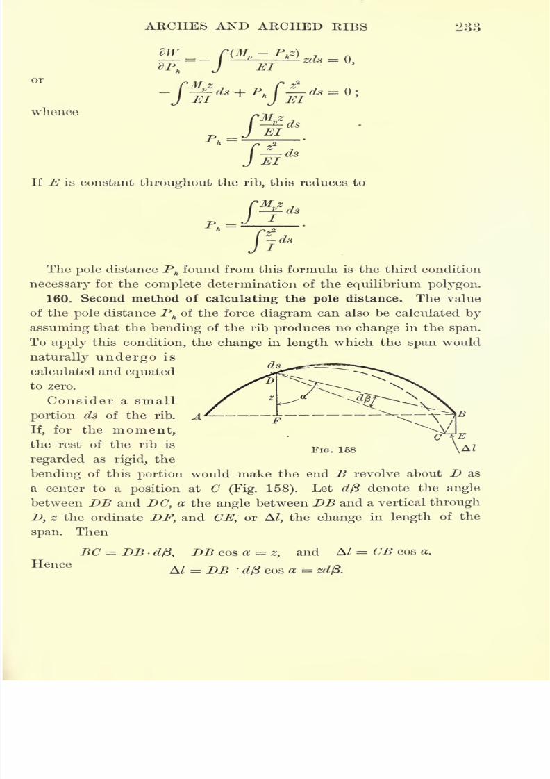
7/30/2019 Textbook on Streng 00 Slo Crich
http://slidepdf.com/reader/full/textbook-on-streng-00-slo-crich 275/433
ARCHES AND ARCHED RIBS 233
or
whence
T> /Mpz
/-*If E is constant throughout the rib, this reduces to
j-fdsPh=
The pole distance Phfound from this formula is the third condition
necessary for the complete determination of the equilibrium polygon.
160. Second method of
calculatingthe
pole
distance. The value
of the pole distance Phof the force diagram can also be calculated by
assuming that the bending of the rib produces no change in the span.
To apply this condition, the change in length which the span would
naturally undergo is
calculated and equated
to zero.
Consider a small
portion ds of the rib.
If, for the moment,
the rest of the rib is
regarded as rigid, the
bending of this portion would make the end B revolve about D as
a center to a position at C(Fig. 158). Let d/3 denote the angle
between
DBand
DC,a the
anglebetween
DBand a vertical
throughD, z the ordinate DF, and CE, or A/, the change in length of the
span. Then
BC = DB dft, DB cos a = z, and A/ = CB cos a.
HenceA/ - DB '
d/3 cos a = zd/3.
FIG lgg
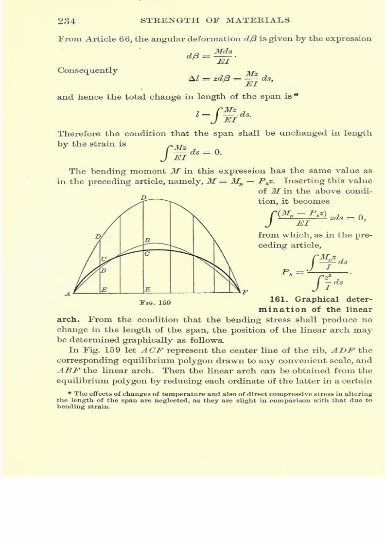
7/30/2019 Textbook on Streng 00 Slo Crich
http://slidepdf.com/reader/full/textbook-on-streng-00-slo-crich 276/433
234 STRENGTH OF MATERIALS
From Article 66, the angular deformation d/3 is given by the expression
_ Mds
Consequently
and hence the total change in length of the span is*
CMz1=1 ds.
Therefore the condition that the span shall be unchanged in length
by the strain is rwds = Q.
J EI
The bending moment M in this expression has the same value as
in the preceding article, namely, M = Mp
Phz. Inserting this value
of If in the above condi-
tion, it becomes
EI
from which, as in the pre-
ceding article,
Pr*?
j jjds
FIG. 159161. Graphical deter-
mination of the linear
arch. From the condition that the bending stress shall produce no
change in the length of the span, the position of the linear arch maybe determined graphically as follows.
In Fig. 159 let ACF represent the center line of the rib, ADF the
corresponding equilibrium polygon drawn to any convenient scale, and
ABF the linear arch. Then the linear arch can be obtained from the
equilibrium polygon by reducing each ordinate of the latter in a certain
* The effects of changes of temperature and also of direct compressive stress in altering
the length of the span are neglected, as they are slight in comparison with that due to
bending strain.
7/30/2019 Textbook on Streng 00 Slo Crich
http://slidepdf.com/reader/full/textbook-on-streng-00-slo-crich 277/433
ARCHES AND ARCHED RIBS 235
ratio, say r. The problem then is to find this ratio r in which the
ordinates to the equilibrium polygon must be reduced to give the
linear arch.
The condition that the span is unchanged in length, derived in
the preceding article, is
hi which z represents the ordinate CE to the rib, and ds an element
of the rib. Since the bending moment M is proportional to the verti-
cal intercept between the linear arch and the center line of the rib,
this condition may be written
*BC-z 7
f El
or, since E may be assumed to be constant and
BC = BE - CE = BE - z,
this condition becomes
which may be written
If r denotes the ratio in which the ordinates to the equilibrium
polygon must be decreased in order to give the linear arch, then
BEr =-DE
and consequently the condition becomes
Cr-DE-z Cz* ,
J- ds- I
jds=Q;whence
DE-z
fThis expression for r can be evaluated graphically by replacing
the integrals by summations and calculating the given functions for a
7/30/2019 Textbook on Streng 00 Slo Crich
http://slidepdf.com/reader/full/textbook-on-streng-00-slo-crich 278/433
236 STRENGTH OF MATERIALS
series of vertical sections taken at equal intervals along the rib. Thus,
since ds in this case is constant,
r =
I
in which the functions under the summation signs are to be calculated
for each section separately, and their sum taken. After r has been
found in this way the linear arch is obtained by decreasing the
ordinates of the equilibrium polygon in the ratio r : 1, and the stress
can then be calculated as explained in Article 157.
This method of determining the linear arch is due to Ewing.
162. Temperature stresses in two-hinged arched rib. When the
temperature of an arched rib changes, the length of the rib also changes,
and consequently stresses called temperature stresses are produced in
the rib (compare Article 19). To calculate the amount of this stress
let L denote the coefficient of linear expansion and T the change in
temperature in degrees. Then each element of the rib of length ds
changes its length by the amount LTds, the horizontal projection of
which is LTdx. Therefore the total change I in the length of the rib is
1= CC
LTdx = 2cLT,Jo
where 2 c is the span. From Article 160, the total change in length
of the span is given by the expression
I
Therefore
_ f*Mz
~Jo El
f**-2Jo El
cLT.
.0El
To simplify this expression assume that the modulus of elasticity
E is constant throughout the rib, and that the moment of inertia /
dsincreases towards the abutments in the ratio Under this assump-
dsdx
tion /= I -> where J denotes the moment of inertia at the crown,
dx
and the above equation becomes
I
El.
Mzdx = 2 cLT,
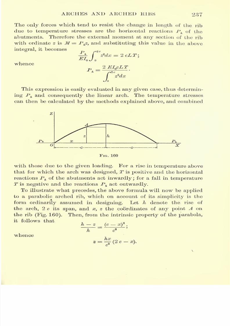
7/30/2019 Textbook on Streng 00 Slo Crich
http://slidepdf.com/reader/full/textbook-on-streng-00-slo-crich 279/433
ARCHES AND ARCHED RIBS 237
The only forces which tend to resist the change in length of the rib
due to temperature stresses are the horizontal reactions Ph
of the
abutments. Therefore the external moment at any section of the rib
with ordinate z is M= Phz, and substituting this value in the above
integral, it becomes
whence2 EI
QcLT
z2dx
This expression is easily evaluated in any given case, thus determin-
ing Phand consequently the linear arch. The temperature stresses
can then be calculated by the methods explained above, and combined
>l
FIG. 160
with those due to the given loading. For a rise in temperature above
that for which the arch was designed, T is positive and the horizontal
reactions Phof the abutments act inwardly ;
for a fall in temperature
T is negative and the reactions Phact outwardly.
To illustrate what precedes, the above formula will now be applied
to a parabolic arched rib, which on account of its simplicity is the
form ordinarily assumed in designing. Let h denote the rise of
the arch, 2 c its span, and x, z the coordinates of any point A on
the rib(Fig. 160). Then, from the intrinsic property of the parabola,
it follows thath z (c x) .
"T" ~~s~whence
fix ._ ,
z = (2 c -x).
c
7/30/2019 Textbook on Streng 00 Slo Crich
http://slidepdf.com/reader/full/textbook-on-streng-00-slo-crich 280/433
238 STRENGTH OF MATERIALS
/czzdx and integrating,
we have
f
2
Jf
Consequently for a parabolic arched rib the horizontal reaction of
the abutments due to a change in temperature of T degrees is
^A =
163. Continuous arched rib fixed at both ends. For a continuous
arched rib fixed at both ends the problem of constructing the equi-
librium polygon is subject to a threefold indetermination, since none
of the three conditions necessary for its determination are given.
The theoretical solution of the question by the principle of least
work is as follows.
Let the vertical reaction
R^tthe horizontal reaction P
h,and the
bending moment M at the left support be chosen as the three
unknown quantities necessary to determine the linear arch. For a
system of concentrated loads the moment M at any section of the
rib distant x from the left support is
M = M + Ex - Phz -V P(x
-d),
in which d is the distance of any load P from the left support, and
the summation is to be extended over all the loads between the left
support and the point under consideration. Similarly, for a uniform
load of amount w per unit of length,
Now, from Article 73, the work of deformation W is given by the
expression
in which M has the value given by one or the other of the above
expressions, depending on whether the loading is concentrated or
uniform. To apply Castigliano's theorem to this expression it is
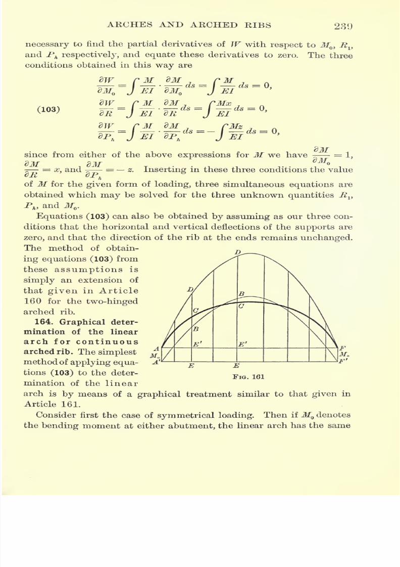
7/30/2019 Textbook on Streng 00 Slo Crich
http://slidepdf.com/reader/full/textbook-on-streng-00-slo-crich 281/433
ARCHES AND ARCHED RIBS 239
necessary to find the partial derivatives of W with respect to M,Rv
and Ph respectively, and equate these derivatives to zero. The three
conditions obtained in this way are
dW M dM Mx(103) ^= ^7-^ ds =
M
since from either of the above expressions for M we have
=x, and
- = z. Inserting in these three conditions the value
h
of M for the given form of loading, three simultaneous equations are
obtained which may be solved for the three unknown quantities Rv
Ph ,and M .
Equations (103) can also be obtained by assuming as our three con-
ditions that the horizontal and vertical deflections of the supports are
zero, and that the direction of the rib at the ends remains unchanged.
The method of obtain-D
ing equations (103) from
these assumptions is
simply an extension of
that
given
in Article
160 for the two-hinged
arched rib.
164. Graphical deter-
mination of the linear
arch for continuous
arched rib. The simplest
method of applying equa-
tions (103) to the deter-
mination of the linear
arch is by means of a graphical treatment similar to that given in
Article 161.
Consider first the case of symmetrical loading. Then ifM denotes
the bending moment at either abutment, the linear arch has the same
E'
E
FIG. 161
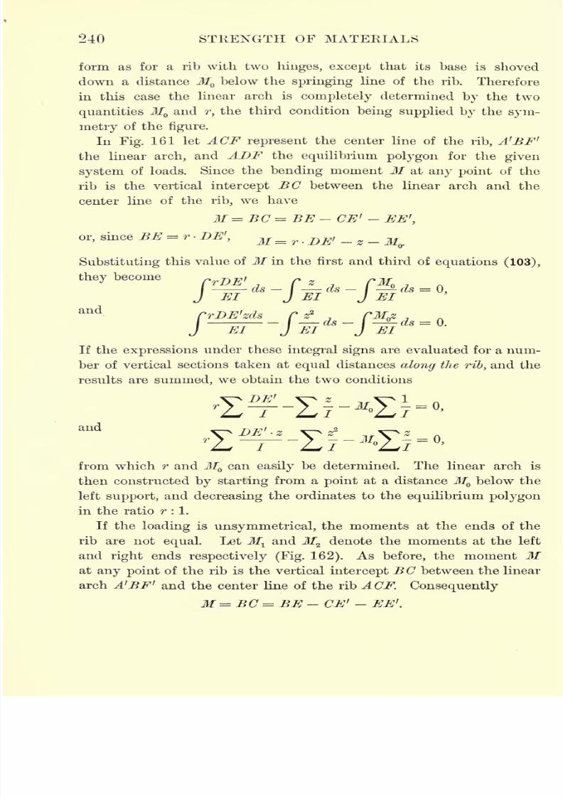
7/30/2019 Textbook on Streng 00 Slo Crich
http://slidepdf.com/reader/full/textbook-on-streng-00-slo-crich 282/433
240 STRENGTH OF MATERIALS
form as for a rib with two hinges, except that its base is shoved
down a distance M below the springing line of the rib. Therefore
in this case the linear arch is completely determined
bythe two
quantities M and r, the third condition being supplied by the sym-
metry of the figure.
In Fig. 161 let ACF represent the center line of the rib, A'BF'
the linear arch, and ADF the equilibrium polygon for the given
system of loads. Since the bending moment M at any point of the
rib is the vertical intercept BC between the linear arch and the
center line of the rib, we have
M=BC = BE-CE* -EE',
or, since BE = r-DE', M=r . DE> - Z-MV
Substituting this value of M in the first and third of equations (103),
they become
CrDE'zds_rj?_ TM^J El J El J El
If the expressions under these integral signs are evaluated for a num-
ber of vertical sections taken at equal distances along the rib, and the
results are summed, we obtain the two conditions
from which r and M can easily be determined. The linear arch is
then constructed by starting from a point at a distance M below the
left support, and decreasing the ordinates to the equilibrium polygon
in the ratio r : 1.
If the loading is unsymmetrical, the moments at the ends of the
rib are not equal. Let Mland M
2denote the moments at the left
and right ends respectively (Fig. 162). As before, the moment Mat any point of the rib is the vertical intercept BC between the linear
arch A'BF' and the center line of the rib ACF. Consequently
M = BC = BE - CE' - EE'.
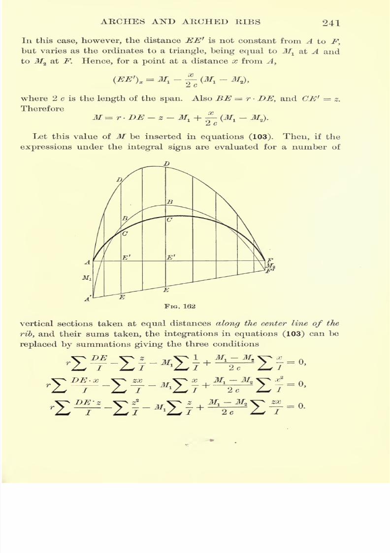
7/30/2019 Textbook on Streng 00 Slo Crich
http://slidepdf.com/reader/full/textbook-on-streng-00-slo-crich 283/433
ARCHES AND ARCHED RIBS 241
In this case, however, the distance EE* is not constant from A to F,
but varies as the ordinates to a triangle, being equal to Mlat A and
to M2at F. Hence, for a point at a distance x from A,
(EE')X= M
l
- -(M,
-
where 2 c is the length of the span. Also BE = r - DE, and CIS' = z.
Therefore
M = r DE - z - M, -f-(M.
- Mz).
2 c
Let this value of M be inserted in equations (103). Then, if the
expressions under the integral signs are evaluated for a number of
vertical sections taken at equal distances along the center line of the
rib, and their sums taken, the integrations in equations (103) can be
replaced by summations giving the three conditions
DE ^z
^f\^1
-T-L-I- M^LJzx
ZDE-z--
2c
7/30/2019 Textbook on Streng 00 Slo Crich
http://slidepdf.com/reader/full/textbook-on-streng-00-slo-crich 284/433
242 STEENGTH OF MATEEIALS
Solving these three equations simultaneously for MltM
2 ,and r, the
linear arch is constructed by laying off Mland M
2from A and F
respectively, and then reducing the ordinates to the equilibrium
polygon in the ratio r : 1, and laying them off from the line A'F'.
The stresses in the rib can then be calculated by the methods
previously given (Article 157).
165. Temperature stresses in continuous arched rib. Using the
notation of Article 162, the change in the length of the span due to
a change in temperature of T degrees is
/ = 2 cLT.
Therefore, for temperature stresses equations (103) become
Mz
~EI
MX , rJ
zis ~~
'
J *
By hypothesis, the only external forces acting on the rib are the
reactions and moments at the abutments due to the temperature
stresses. Consequently, if R denotes the vertical reaction, Phthe hori-
zontal reaction, and M^ the moment at the left abutment, the moment
M at any other point of the rib is
M= M^ + Rx- Phz.
If, then, this value of M is inserted in the above integrals and the
resulting equations solved simultaneously forMlt R, and P
h)the linear
arch is thereby determined.
7/30/2019 Textbook on Streng 00 Slo Crich
http://slidepdf.com/reader/full/textbook-on-streng-00-slo-crich 285/433
CHAPTER XI
FOUNDATIONS AND RETAINING WALLS*
166. Bearing power of soils. Since the character of a foundation
is dependent upon the nature of the soil on which it is to rest, it is
necessaryin
designinga foundation to
knowwith a
reasonable degreeof accuracy the maximum load which the soil can sustain per unit
of area without appreciable settlement; or, in other words, what is
known as the bearing power of the soiLf
Ordinarily the results of previous experience are relied upon to
give an approximate value of the bearing power of any given soil,
and stability is assured by the adoption of a large factor ofsafety.
For structuresof
unusual importance, however,or
when the natureof the soil is uncertain, the results of previous experience are usually
insufficient to assure stability, and special tests are necessary for the
determination of the bearing power of the soil in question. Amongnotable structures for which such special tests have been made may
be mentioned the State Capitol at Albany, N.Y.;the Congressional
Library at Washington, D. C.;the suspension bridges at Brooklyn, N.Y.,
and at Cincinnati, Ohio; the Washington Monument; the Tower
Bridge, London, etc.
By averaging the results of a large number of such tests, reliable
information is furnished as to the bearing power of soils in general.
The most commonly accepted of such average values are those given
by Professor I. O. Baker in his Treatise on Masonry Construction, and
are as shown in the table on the following page. Other values in
common use are also quoted for comparison, and may be accepted as
representative of modern practice.
* For a more detailed treatment of foundations and retaining walls the following
special treatises may be consulted. Baker, Treatise on Masonry Construction ; Howe,
Retaining Walls for Earth; Fowler, Ordinary Foundations; Merriman, Walls and
Dams; Patton, Ordinary Foundations.
t The bearing power of soils is analogous to what is called the crushing strength in
the case of more rigid materials, such as stone and brick.
243
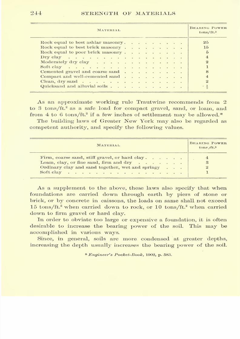
7/30/2019 Textbook on Streng 00 Slo Crich
http://slidepdf.com/reader/full/textbook-on-streng-00-slo-crich 286/433
244 STRENGTH OF MATERIALS
MATERIAL,
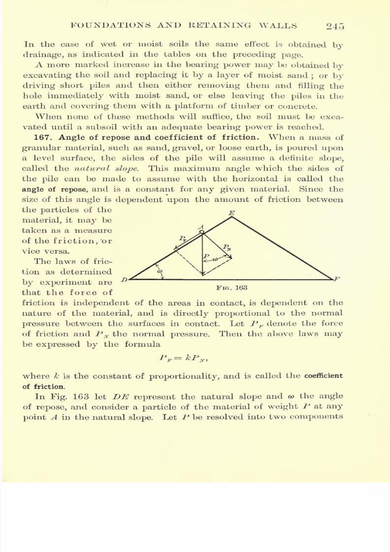
7/30/2019 Textbook on Streng 00 Slo Crich
http://slidepdf.com/reader/full/textbook-on-streng-00-slo-crich 287/433
FOUNDATIONS AND RETAINING WALLS 245
In the case of wet or moist soils the same effect is obtained by
drainage, as indicated in the tables on the preceding page.
A more marked increase in the bearing power may be obtained by
excavating the soil and replacing it by a layer of moist sand;or by
driving short piles and then either removing them andfilling the
hole immediately with moist sand, or else leaving the piles in the
earth and covering them with a platform of timber or concrete.
When none of these methods will suffice, the soil must be exca-
vated until a subsoil with an adequate bearing power is reached.
167. Angle of repose and coefficient of friction. When a mass of
granular material, such as sand, gravel, or loose earth, is poured upon
a level surface, the sides of the pile will assume a definite slope,
called the natural slope. This maximum angle which the sides of
the pile can be made to assume with the horizontal is called the
angle of repose, and is a constant for any given material. Since the
size of this angle is dependent upon the amount of friction between
the particles of the
material, it may be
taken as a measure
of the friction, "or
vice versa.
The laws of fric-
tion as determined
by experiment are
/that the force of
friction is independent of the areas in contact, is dependent on the
nature of the material, and is directly proportional to the normal
pressure between the surfaces in contact. Let PF denote the force
of friction and PN the normal pressure. Then the above laws may
be expressed by the formula
P-Z-P
F ^-L N>
where k is the constant of proportionality, and is called the coefficient
of friction.
In Fig. 163 let DE represent the natural slope and o> the angle
of repose, and consider a particle of the material of weight P at any
point A in the natural slope. Let P be resolved into two components
FIG. 163
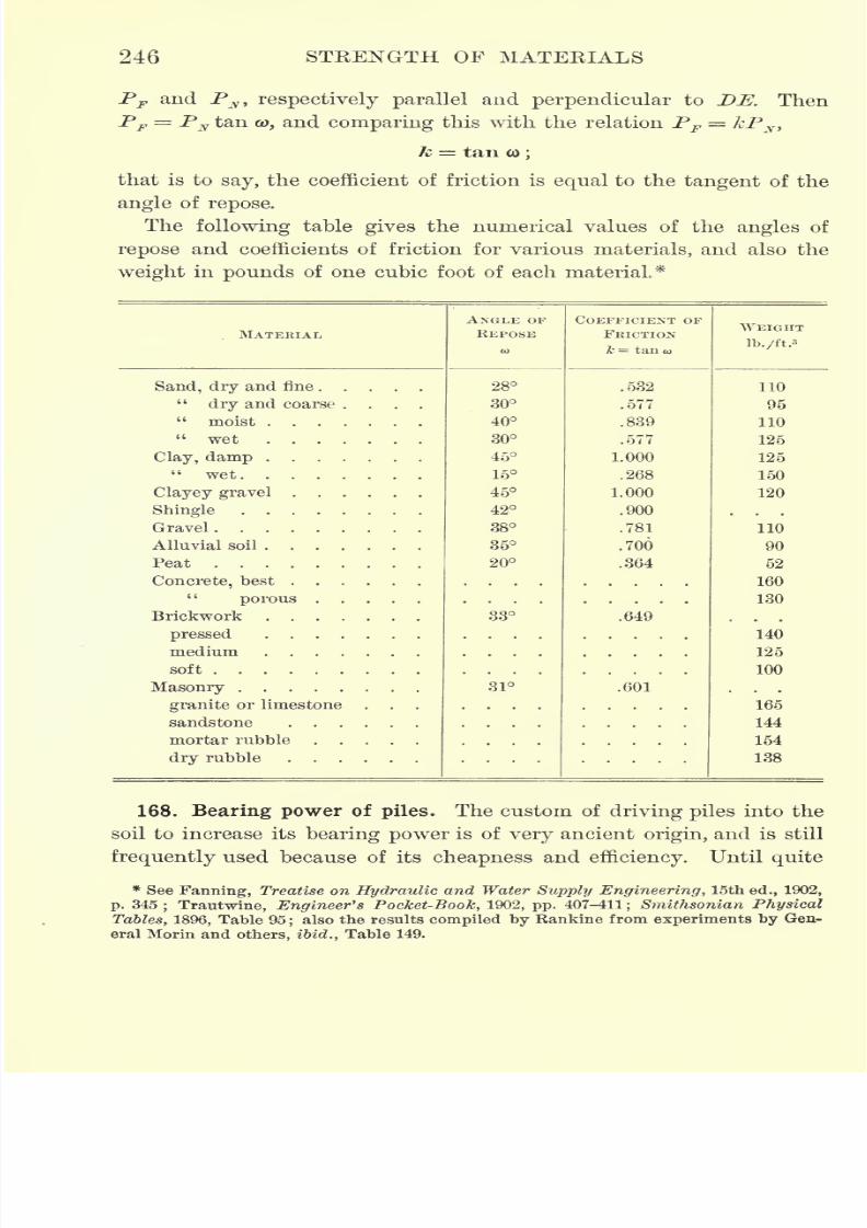
7/30/2019 Textbook on Streng 00 Slo Crich
http://slidepdf.com/reader/full/textbook-on-streng-00-slo-crich 288/433
246 STKENGTH OF MATERIALS
PF and Py, respectively parallel and perpendicular to DE. Then
PF = PN tan a), and comparing this with the relation PF kPN >
k = tan CD;
that is to say, the coefficient of friction is equal to the tangent of the
angle of repose.
The following table gives the numerical values of the angles of
repose and coefficients of friction for various materials, and also the
weight in pounds of one cubic foot of each material*
MATERIAL,
7/30/2019 Textbook on Streng 00 Slo Crich
http://slidepdf.com/reader/full/textbook-on-streng-00-slo-crich 289/433
FOUNDATIONS AND RETAINING WALLS 247
recently wood was the only material used forpiles, and they were
either driven by hand with sledges, or by means of a block, usually
of metal, which was raised between two upright guides and allowed
to fall on the head of the pile. The latter form of pile driver is still
in frequent use for driving woodenpiles, and is called the drop-
hammer pile driver.
In 1839 Nasmyth invented the steam pile driver, which consists
essentially of a steam cylinder supported vertically above the head
of the pile by two uprights fastened to a cap which rests on the
pile.The hammer in this case is a weight attached to the piston
rod, and delivers a blow on the head of the pile at each stroke
of the piston. The uprights which support the cylinder also serve
as guides for the hammer, which varies in weight from 550 Ib. to
4800 Ib. This form of pile driver owes its efficiency to the rapidity
with which the blows can be given, the number being from sixty
to eighty per minute, thus preventing the soil from recovering its
equilibrium between strokes, and greatly decreasing its resistance to
penetration.
In modern engineering practice cast-iron and concrete piles are rap-
idly coming into use, and as neither of these materials is capable
of standing repeated blows, piles of this kind are usually driven by
means of an hydraulic jet.The jet is attached to the point of the
pile, thus constantly excavating the soil in front of the pile as it
descends, and enabling it to sink into place with little or no assist-
ance other than its own weight.
The rational formulas in ordinary use for determining the bearing
power of piles are based upon the assumption that the pile is driven
by a drop-hammer pile driver, and express its bearing power in terms
of the amount of penetration at the last blow. Since the bearing
power of a pile is due in part to the friction of the earth on the sides
of the pile, as well as to the resistance of the subsoil to penetration,
and also since part of the energy of the hammer is absorbed by the
friction of the guides, in compressing the head of the pile,in compress-
ing the hammer, in overcoming the inertia of the pile, etc., a rigorous
formula is too complicated to be of much practical value, although
there are a number of elaborate discussions of the bearing power of
piles which take all of these elements into consideration, notably the
7/30/2019 Textbook on Streng 00 Slo Crich
http://slidepdf.com/reader/full/textbook-on-streng-00-slo-crich 290/433
248 STRENGTH OF MATERIALS
theories of Kankine and Weisbacli.* However, as several of the ele-
ments entering into the discussion are attended with considerable
uncertainty, it is customary in practice to use either an empirical
formula or the simple approximate formula deduced below, adopting
a factor of safety large enough to cover the assumptions made.
Let P denote the weight of the hammer in pounds, h the height
of the fall in inches, R the average resistance of the soil to penetra-
tion during the last blow in pounds, and d the penetration of the
pile,due to the last blow, in inches. Then, assuming that all the work
done by the hammer is expended in overcoming the resistance of the
earth at the point of the pile, we have
Ph = Rd.
With a factor of safety of 6, the approximate formula for safe load
on the pile becomes
(104) S = .
As the head of a timber pile becomes " broomed"
by repeated blows,
and this greatly decreases the efficiency of the blow by absorbing the
kinetic energy of the hammer, the head should be sawed off to a solid
surface before making a test blow for determining the bearing power
of the pile.
For a drop-hammer pile driver the empirical formula in most
common use is
2Ph(105) K =
dTl'the notation being the same as above, and the factor of safety being 6.
For a steam pile driver this formula becomes
<"> "iSn-where Ph represents the kinetic energy of the hammer.
The above empirical formula, (105) or (106), is commonly known
as Wellington's formula, or the Engineering News formula, and has been
incorporated in the building laws of Greater New York.
The only means of determining the bearing power of a pile driven
by an hydraulic jet,is to observe the maximum load it can support
without appreciable settlement.
* See Baker, Treatise on Masonry Construction, chap. xi.
7/30/2019 Textbook on Streng 00 Slo Crich
http://slidepdf.com/reader/full/textbook-on-streng-00-slo-crich 291/433
FOUNDATIONS AND RETAINING WALLS 249
Problem 289. A one-ton hammer falls 15 ft. on the head of a pile, and the
settlement is observed to be . 1 in. Calculate the safe load for the pile by formulas
(104) and (105) and compare the results.
Problem 290. Under what conditions will the approximate rational formula
(104) and the Engineering News formula (105) give substantially the same results?
Solution. If the values of B obtained from these two formulas were equal, then
=;whence d
Jj-in. For other values of d the rational formula gives the
greater value of the bearing power when d < -fain.
,and the empirical formula gives
the greater value when d > TJ
T in. From this it follows that the empirical formula
is only applicable when the settlement at the last blow is small.
169. Ordinary foundations. Although the foundation of a struc-
ture is necessarily the first part to be constructed, it is the last part
to be designed, for the weight of the structure determines the nature
of the foundation, and this cannot be calculated until the structure
has assumed definite proportions.
The load which a structure is designed to carry consists primarily
of three parts.
1. The dead load, due to the weight of the structure and the per-
manent fixtures, such as plumbing and heating apparatus, elevators,
water tanks, machinery, etc.
2. The live load, which depends on the use to which the structure
is to be put, and which may vary from 20 lb./ft.2to 400 lb./ft.
2
3. The wind load, due to the overturning action of the wind upon
the side of the structure. These three parts of the total load must
be calculated separately and then combined so as to give the maxi-
mum resultant. The area of the foundation is then found at once
by dividing this maximum load by the safe bearing power of the soil.
The chief concern in designing a foundation, however, is not that
its settlement shall be zero, but that it shall be uniform throughout.
For if one part of a foundation settles more than another, it is evident
that cracks are bound to occur which will seriously weaken the struc-
ture and may even destroy its usefulness altogether. Since uniformity
of settlement implies uniformity of pressure on the soil, the condition
which determines the stability of a foundation and its superstructure
is simply uniformity of pressure on the soil.
The effect of violating this condition is frequently seen, the most
common instance being that of ordinary dwelling houses in which
several openings, say a door and a number of windows, occur one
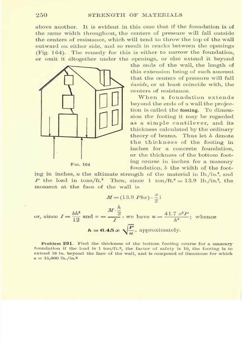
7/30/2019 Textbook on Streng 00 Slo Crich
http://slidepdf.com/reader/full/textbook-on-streng-00-slo-crich 292/433
250 STRENGTH OF MATERIALS
above another. It is evident in this case that if the foundation is of
the same width throughout, the centers of pressure will fall outside
the centers of resistance, which will tend to throw the top of the wall
outward on either side, and so result in cracks between the openings
(Fig. 164). The remedy for this is either to narrow the foundation,
or omit it altogether under the openings, or else extend it beyond
the ends of the wall, the length of
this extension being of such amount
that the centers of pressure will fall
inside, or at least coincide with, the
centers of resistance.
When a foundation extends
beyond the ends of a wall the projec-
tion is called the footing. To dimen-
sion the footing it may be regarded
as a simple cantilever, and its
thickness calculated by the ordinary
theory of beams. Thus let h denote
the thickness of the footing in
inches for a concrete foundation,
or the thickness of the bottom foot-
ing course in inches for a masonry
foundation, b the width of the foot-
ing in inches, u the ultimate strength of the material in lb./in.2
,and
P the load in tons/ft.2
Then, since 1 ton/ft.2
= 13.9 lb./in.2
,the
moment at the face of the wall is
FIG. 164
jr.*
Tbh
*
A 2t,
41.7 ,
or, since /= and u =- > we have u =---;whence
2i I h
fph = 6.45 x -\] , approximately.
Problem 291. Find the thickness of the bottom footing course for a masonryfoundation if the load is 1 ton/ft.
2,the factor of safety is 10, the footing is to
extend 18 in. beyond the face of the wall, and is composed of limestone for which
u = 15,000 lb./in.2
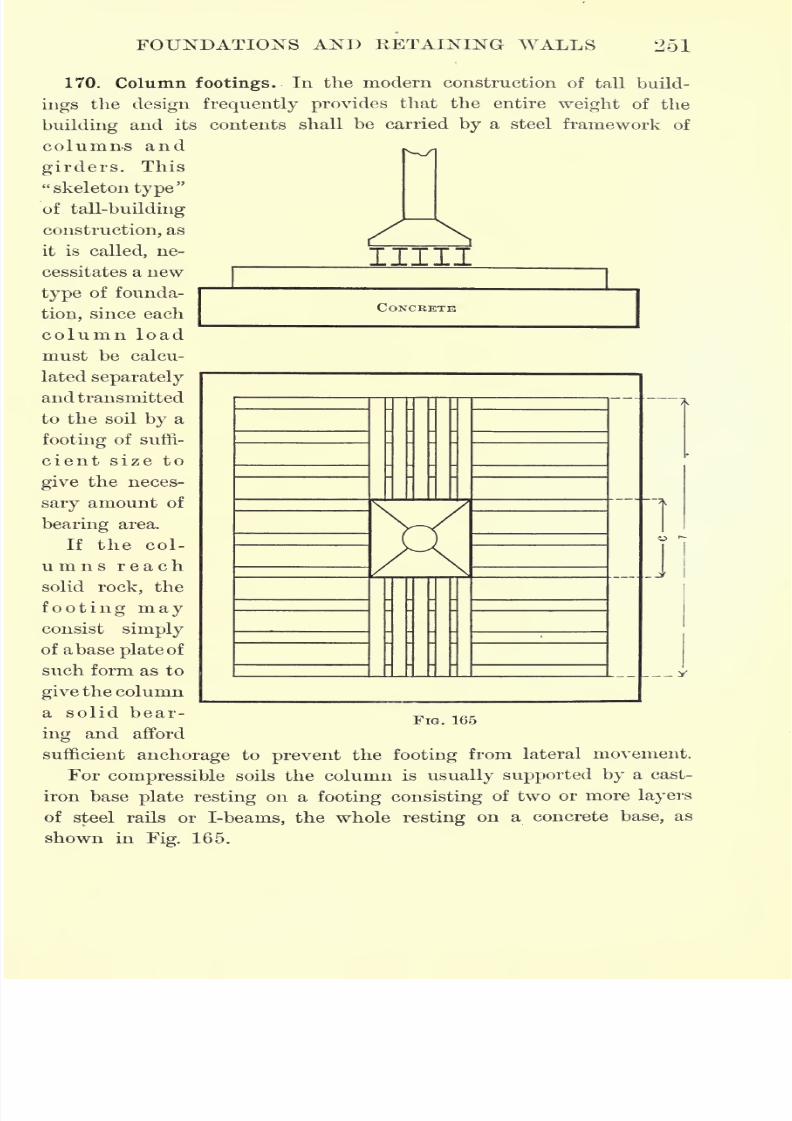
7/30/2019 Textbook on Streng 00 Slo Crich
http://slidepdf.com/reader/full/textbook-on-streng-00-slo-crich 293/433
FOUNDATIONS AND EETAINING WALLS 251
IIII
CONCRETE
170. Column footings. In the modern construction of tall build-
ings the design frequently provides that the entire weight of the
building and its contents shall be carried by a steel framework of
columns and
girders. This
"skeleton type"
of tall-building
construction, as
it is called, ne-
cessitates a new
type of founda-
tion, since each
column load
must be calcu-
lated separately
and transmitted
to the soil by a
footing of suffi-
cient size to
give the neces-
sary amount of
bearing area.
If the col-
umns reach
solid rock, the
footing mayconsist simply
of abase plate of
such form as to
give the column
a solid bear-
ing and afford
sufficient anchorage to prevent the footing from lateral movement.
For compressible soils the column is usually supported by a cast-
iron base plate resting on a footing consisting of two or more layers
of steel rails or I-beams, the whole resting on a concrete base, as
shown in Fig. 165.
J
FIG. 165
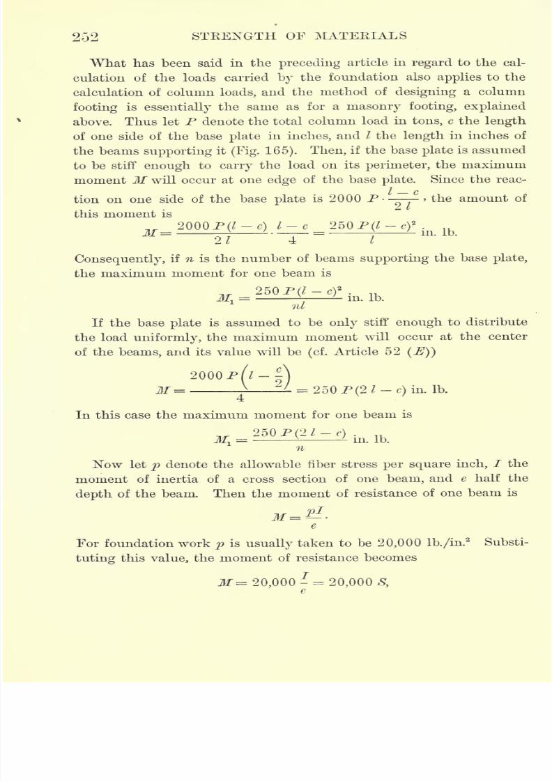
7/30/2019 Textbook on Streng 00 Slo Crich
http://slidepdf.com/reader/full/textbook-on-streng-00-slo-crich 294/433
252 STRENGTH OF MATERIALS
What has been said in the preceding article in regard to the cal-
culation of the loads carried by the foundation also applies to the
calculation of column loads, and the method of designing a column
footing is essentially the same as for a masonry footing, explained
above. Thus let P denote the total column load in tons, c the length
of one side of the base plate in inches, and I the length in inches of
the beams supporting it (Fig. 165). Then, if the base plate is assumed
to be stiff enough to carry the load on its perimeter, the maximum
moment M will occur at one edge of the base plate. Since the reac-
tion on one sideof
thebase
plateis 2000
P--^>the amount of
this moment is
2000P(/-c) l-e 250P(/-c)2
.
~2l~~
~T
Consequently, if n is the number of beams supporting the base plate,
the maximum moment for one beam is
250P(/-c)2
.
M. = ^'
in. Ib.
nl
If the base plate is assumed to be only stiff enough to distribute
the load uniformly, the maximum moment will occur at the center
of the beams, and its value will be(cf.
Article 52 (E))
2000 P('-D.=-i-=L = 250 P(2 I
-c)
in. Ib.
In this case the maximum moment for one beam is
250P(2J-f) .
M, =- in. Ib.
n
Now let p denote the allowable fiber stress per square inch, / the
moment of inertia of a cross section of one beam, and e half the
depth of the beam. Then the moment of resistance of one beam is
For foundation work p is usually taken to be 20,000 lb./in.2
Substi-
tuting this value, the moment of resistance becomes
M= 20,000- = 20,000 S,e
7/30/2019 Textbook on Streng 00 Slo Crich
http://slidepdf.com/reader/full/textbook-on-streng-00-slo-crich 295/433
FOUNDATIONS AND RETAINING WALLS 253
where S denotes the section modulus. Equating the moment of
resistance to the external bending moment and solving theresulting
equation for S, we have in the first case
SO In
and in the second case T> /*> 7 \^ I C)
In designing a column footing the column load P is first calculated,
and the area of the footing determined by dividing the column load
bythe safe
bearing powerof the soil. The size of base
plate
and
number of beams supporting it are next assumed, and the section
modulus calculated by one of the above formulas. The size of beam to
be used is then determined by choosing from the tables a beam whose
section modulus agrees most closely with the calculated value of S.
Problem 292. Design the footing for a column supporting~a load of 400 tons,
and resting on a base plate 4 ft. square, so that the pressure on the foundation bed
shall not exceed 3 tons/ft.2
171. Maximum earth pressure against retaining walls. A wall
of concrete or masonry built to sustain a bank of earth, or other
loose material, is called a retaining wall.
In Chapter X it was shown that in order to determine the stability
of an arch three conditions were necessary, which might conveniently
be chosen as the direction, amount, and point of application of the
resultant pressure on any cross section of the arch ring. The same
necessity arises in the discussion of retaining walls, namely, that three
conditions are necessary for the complete solution of the problem,
and a number of theories have been advanced, notably those of
Coulomb, Weyrauch, and Eankine, based on different assumptions as
to these conditions.
All theories, however, agree upon two of these assumptions, namely,
(1) that the pressure against the wall is due to a wedge of earth, or,
in other words, that the surface along which the earth tends to slide
against the wall is a plane ;and
(2)that the point of application of
the resultant earth pressure is one third of the height of the wall
from the bottom. Neither of these assumptions is rigorously correct,
for the first is equivalent to neglecting the cohesion of the earth, and
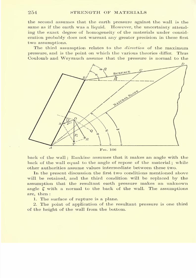
7/30/2019 Textbook on Streng 00 Slo Crich
http://slidepdf.com/reader/full/textbook-on-streng-00-slo-crich 296/433
254 STRENGTH OF MATERIALS
the second assumes that the earth pressure against the wall is the
same as if the earth was a liquid. However, the uncertainty attend-
ing the exact degree of homogeneity of the materials under consid-
eration probably does not warrant any greater precision in these first
two assumptions.
The third assumption relates to the direction of the maximum
pressure, and is the point on which the various theories differ. Thus
Coulomb and Weyrauch assume that the pressure is normal to the
D
FIG. 166
back of the wall;Rankine assumes that it makes an angle with the
back of the wall equal to the angle of repose of the material;while
other authorities assume values intermediate between these two.
In the present discussion the first two conditions mentioned above
will be retained, and the third condition will be replaced by the
assumption that the resultant earth pressure makes an unknown
angle with a normal to the back of the wall. The assumptions
are, then :
1. The surface of rupture is a plane.
2. The point of application of the resultant pressure is one third
of the height of the wall from the bottom.
7/30/2019 Textbook on Streng 00 Slo Crich
http://slidepdf.com/reader/full/textbook-on-streng-00-slo-crich 297/433
FOUNDATIONS AND RETAINING WALLS 255
3. The resultant pressure is inclined at an angle to a normal to
the back of the wall.
From the result of the theory based on these assumptions, the
values of the resultant earth pressure given by Coulomb, Weyrauch,
Kankine, and others will then be deduced as special cases by giving
different values to f,
In Fig. 166 let AB represent the back of the wall, BD the surface
of the ground, AD the natural slope, and A Cany line included between
AB and AD. Also let P' denote the resultant pressure due to the
wedge BAC, Plthe weight of this wedge, OR its reaction against
the plane AC, the angle between Pf
and a normal to the back of
the wall, <w the angle of repose of the earth, a the angle between the
back of the wall and the horizontal, ft the angle between the surface
of the ground and the horizontal, and x the angle between AC and
the horizontal.
Then in the triangle TOS, by the law of sines,
,si
l
s
or, since TOR=x-o> and mS=180-a ?, we have OST=a+-x+a),
and, consequently, /
pl = psin
(a; -ft))1
sin (a + f -f- &) x)
To find an expression for Pv let w denote the weight of a unit
volume of the material, say the weight of one cubic foot. Then for a
section of unit length in the direction of the wall
in
Pl=
w(area ABC) = -AB - AC sin BAC;
z>
or, if k denotes the height of the wall, AB = -7 > BA C = a - x,'
( _ R\sma
and AC = ABsm (*-P) . whencesin (x j3)
_ wlizsin (a ft)
sin (a x)
2 sin2a sin(x ft)
and, consequently,
, _ wb? sin (a ft)sin (a x)sin(x ft))
~2 sin
2a; siu(x
-ft)siu(a ++&)- x)
7/30/2019 Textbook on Streng 00 Slo Crich
http://slidepdf.com/reader/full/textbook-on-streng-00-slo-crich 298/433
256 STRENGTH OF MATERIALS
The problem now consists in finding the value of the variable angle
x for which Pr
is a maximum, which may be expressed symbolically
by
the conditions ,
p/
~ = anddx x
In order to reduce the expression for P' to a form more suitable for
differentiation, we make use of the following identity.
cos (a x) cos (a &>)cot (a x) cot (a
&>)=
sin (a x) sin (a &>)
cos (a x) sin (a co)cos (a o>)
sin (a x)
sin (a x)sin (a &>)
__sin (x ft>)
sin (a x)sin (# &>)'
whence
sin (x ft>)= sin (a #)
sin (a &>) [cot (a x) cot (a o>)].
Similarly,
sin (x P)= sin (a a?)
sin (a j3) [cot (a x) cot (# /3)],
and
sin (a + &) + f a?)= sin
(or #)sin
(&> + f) [cot (a x) cot(o> -f ?)].
Substituting these values in the expression for P', the latter becomes
iwh* sin (a CD)
cot (a x) cot (a &>)~~
2sin2# sin(a)+f) [cot (-#) cot (a /S)][cot(a #)+ cot (&)+?)]
Now the terms in this expression which contain the variable x are
all of the same form,namely,
cot
(a x).
This term
maytherefore
be replaced by a new variable ytand the remaining terms by letters
denoting constants. Thus let
wh2sin (a co)
cot (a x)=
y,- = A,
2 sin2a sin
(o> + ?)
cot (a a>)=B, cot (a-
/3)= C, cot(&> + ?)= D.
Equating to zero the first derivative of P' with respect to yywe have
= ^ (y-
C)(y + J)-(y-
J3)(y-C)-(y
-
<fy
"
(y-
c-)
2
(2/ + vf
whence the condition for a maximum is
= B +(#- C)(B
7/30/2019 Textbook on Streng 00 Slo Crich
http://slidepdf.com/reader/full/textbook-on-streng-00-slo-crich 299/433
FOUNDATIONS AND KETAINING WALLS 257
Substituting this value of y in the expression for P'tthe latter becomes
or, replacing A, B, C, I) by their values,
^ sin* (a -co)maX
2sin*asin(a + t),
sin(co-
/?)sin
(co"
which is the general formula for the maximum inclined earth pressure
against retaining walls.
The various standard theories as to the maximum eartli pressure
may now be obtained as special cases of the above general formula
by making the following assumptions.*
1. Weyrauch's formula. Assume that the pressure is normal to
the back of the wall. Then f 0, arid formula (107) becomes
P'= sin
2
(a o>)
>. a A I sin
(ft) /3)sin co\2
2sm3
o:(1 -f- A -I
\ M sm (a p) sin aj
2. Rankine's formula. Assume that the angle of repose of earth
on masonry is equal to the angle of repose of earth on earth. Then
f = co, and formula (107) becomes
,wh* sin
2
(a co)1
max ~2sm2tfsin(o; + co)
/ I
sin(o) - ft)sin 2 a>
3. Poncelet's formula. In Eankine's formula assume that the earth
surface is horizontal and the back of the wall is vertical. Then
/3= and a = 90, and the preceding formula becomes
fwh2
cos co
2(l+V2siii&))2
4. Coulomb's formula. Assume, as in 3, that the earth surface is
horizontal and the back of the wall vertical, and make the further
* It is not intended to convey the idea that Weyrauch, Rankine, etc., made these
assumptions explicitly, but that they lead to formulas identical with theirs.
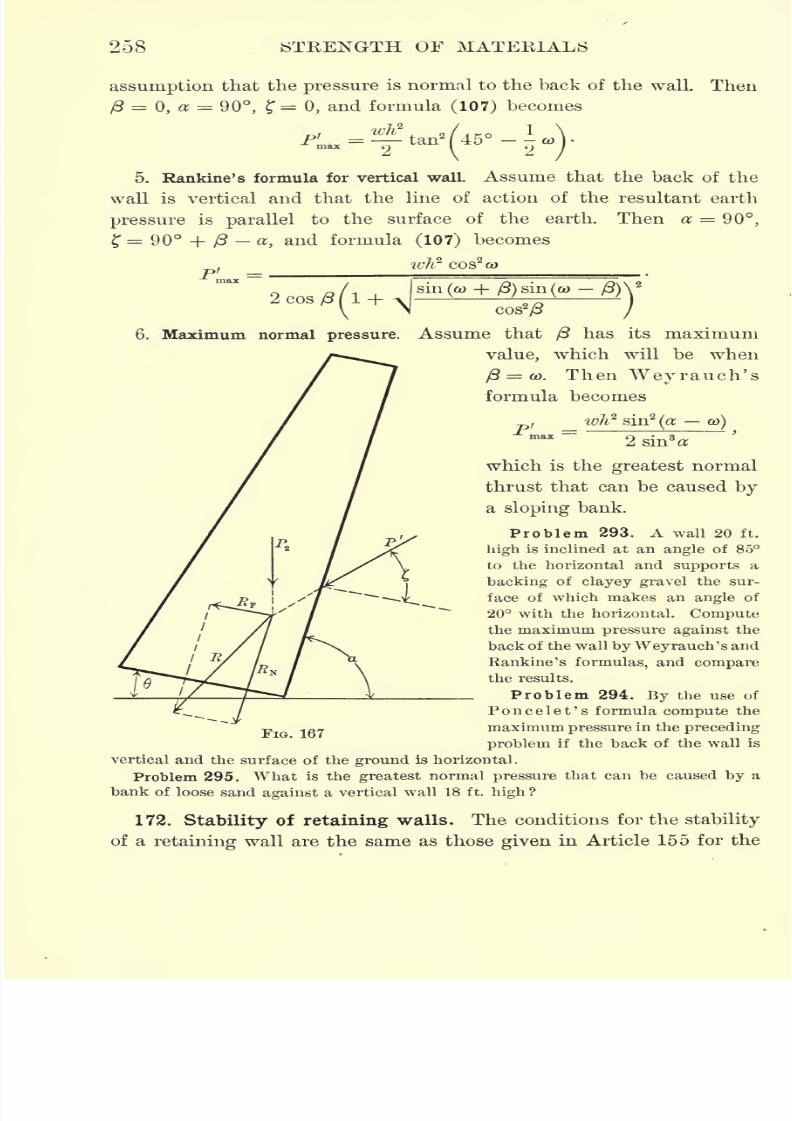
7/30/2019 Textbook on Streng 00 Slo Crich
http://slidepdf.com/reader/full/textbook-on-streng-00-slo-crich 300/433
258 STRENGTH OF MATERIALS
assumption that the pressure is normal to the back of the wall. Then
/3=
0, a = 90, ?= 0, and formula (107) becomes
45-i5. Rankine's formula for vertical wall Assume that the back of the
wall is vertical and that the line of action of the resultant earth
pressure is parallel to the surface of the earth. Then a = 90,
f 90 + /3 a, and formula (107) becomes
, _ ivk2COS
2ft)
^g/i+j^+a^g^jy\M cos
2
/3 i
6. Maximum normal pressure. Assume that /3 has its maximum
value, which will be when
ft= &). Then Wey ranch's
formula becomes
fwh2
sin2
(a ft>)
max= 2 sin3*
which is the greatest normal
thrust that can be caused by
a sloping bank.
Problem 293. A wall 20 ft.
high is inclined at an angle of 85
to the horizontal and supports a
backing of clayey gravel the sur-
face of which makes an angle of
20 with the horizontal. Compute
the maximum pressure against the
back of the wall by Weyrauch's and
Rankine's formulas, and compare
the results.
Problem 294. By the use of
Poncelet's formula compute the
-p -g maximum pressure in the precedingproblem if the back of the wall is
vertical and the surface of the ground is horizontal.
Problem 295. What is the greatest normal pressure that can be caused by a
bank of loose sand against a vertical wall 18 ft. high ?
172. Stability of retaining walls. The conditions for the stability
of a retaining wall are the same as those given in Article 155 for the

7/30/2019 Textbook on Streng 00 Slo Crich
http://slidepdf.com/reader/full/textbook-on-streng-00-slo-crich 301/433
FOUNDATIONS AND RETAINING WALLS 259
stability of abutments, namely, that the wall must be secure against
sliding on its base and against overturning.
Let P2denote the weight of the wall, P' the resultant earth pres-
sure, and R the resultant of P2 and P' (Fig. 167). Then, if R is resolved
into two components RF and RN , respectively parallel and perpen-
dicular to the base of the wall, the condition forstability against
sliding is that RF shall be less than the friction on the base, or,
symbolically,
Let g denote the factor of safety. Then this condition may be written
sr < ksr .
(108) JB,= r.
9
To find the values of RF and RN) let P' and P2be resolved into com-
ponents parallel to RF and Ry respectively. Then, in the notation of
the preceding article,
RF= P'
sin(o; + + f)_ p
asin 6,
RN = P2cos 6 - P' cos(a + 6 + ?).
Substituting these values of RF and RN in equation (108) and solving
the resulting expression forg,
If the base of the wall is horizontal, = and equation (109) becomes
(no)*[P2 -P'cos(*+jr)].
P'sin(a + f)
For security against sliding the factor of safety should not be less
than 3; consequently, the criterion for stability against sliding may
be stated as
f/>3,
where the value of g is calculated from equation (109) or (110).
In applying this criterion it should be noted that the value of f
must first be assumed (Article 171; < ? < a>).
The following table gives average values of the angle of repose
and coefficient of friction of masonry on various substances.*
* See references at the foot of p. 246.
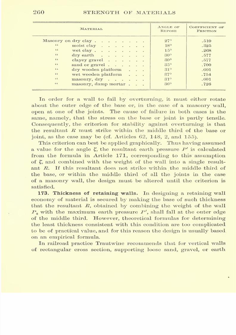
7/30/2019 Textbook on Streng 00 Slo Crich
http://slidepdf.com/reader/full/textbook-on-streng-00-slo-crich 302/433
260 STRENGTH OF MATERIALS

7/30/2019 Textbook on Streng 00 Slo Crich
http://slidepdf.com/reader/full/textbook-on-streng-00-slo-crich 303/433
FOUNDATIONS AND RETAINING WALLS 261
level with the top, the thickness 1} of the base of the wall in terms
of its total height li should be as follows :
*
For wallof
cut stone or.
large rangednibble
fin
mortar,1> = .35 h.
For wall of good common 8cabblcd mortar rubble, or brick,
1> = .40 h.
for wall of well scabbled dry rubble,
1> = .50 h.
These empirical rules may be regarded as representative of the best
American practice, and may be used to give a first approximation in
making a tentative design.
By inclining the wall backward the angle between the earth thrust
P' and the wall is decreased, and consequently the resultant li is
made to approach more nearly the center of the base. This allows
the thickness of the base to be decreased and thus lessens the
amount of material in the wall, although it slightly increases its
depth. However, there is a restriction upon the amount of inclina-
tion which is permissible, for the inclination also has the effect of
increasing the tendency to slide on the base or joints.In practice
these considerations are balanced by inclining the back of the wall
at a small angle, say 5 or 10, to the vertical(i.e.
a = 80 or 85),
and at the same time cutting the footing into steps perpendicular
to the line of action of the resultant R, thus securing economy of
material without sacrificing stability.
The thickness of the top of the wall is determined by the necessity
of providing for the lateral pressure of the earth, due to the action of
frost. Since the action of frost is greatest near the top of the wall
where the material is most exposed, it is likely to push the top over
if the wall is made only thick enough to resist the pressure due
to the weight of the earth. This consideration, therefore, limits the
least thickness of the wall at the top to about two feet for masonry,
or somewhat less than this amount for concrete, since the latter has
no joints and therefore offers a greater moment of resistance.
*Engineer's Pocket-Book, 1902, p. 603.
t Masonry composed of rough, undressed stones is called rubble ;scabbled rubble has
the roughest irregularities knocked off with a hammer.

7/30/2019 Textbook on Streng 00 Slo Crich
http://slidepdf.com/reader/full/textbook-on-streng-00-slo-crich 304/433
262 STRENGTH OF MATERIALS
From the above, it follows that for an economical design the cross
section of a wall should be trapezoidal, the thickness of the base
being determined by the consideration of stability against overturn-
ing, and the thickness of the top by the maximum action of frost.
The inclination of either face of a wall to the horizontal is usually
expressed by giving the ratio of the horizontal projection of this face
to its vertical projection. This ratio is called the batter, and is given
in inches of horizontal projection per foot of height. For example, if
a wall makes an angle of80^-
with the horizontal, it is said to be
" battered 2 to 1," since the ratio of its horizontal projection to its
vertical projection is equal to cot a, and in the present case
cot a = cot 80^= .1673 = ^, approximately.
Problem 296. Design a concrete retaining wall to support a bank of loose earth
25 ft. high, the back of the wall to be inclined backward at a batter of H to 1.
7/30/2019 Textbook on Streng 00 Slo Crich
http://slidepdf.com/reader/full/textbook-on-streng-00-slo-crich 305/433
PART II
PHYSICAL PROPERTIES OF MATERIALS
263
7/30/2019 Textbook on Streng 00 Slo Crich
http://slidepdf.com/reader/full/textbook-on-streng-00-slo-crich 306/433
7/30/2019 Textbook on Streng 00 Slo Crich
http://slidepdf.com/reader/full/textbook-on-streng-00-slo-crich 307/433
PART II
PHYSICAL PROPERTIES OF MATERIALS
CHAPTER XII
IRON AND STEEL
174. Introductory. A study of the properties of materials used in
engineeringconstruction
involves a studyof
the machines used for
making the tests and the method of conducting these tests. From
the time of Galileo, in 1600 A.D., tests have been made to determine
the strength of materials, but only during the past fifty years has any
very great advance been made. The rapid development of the past
half century has been due to the notable increase in the construction
of large buildings, bridges, etc.;for where engineers were formerly
content to use material without being tested, the importance of modernconstructions demands that the physical properties of the materials
used shall be determined for each large contract.
The early testing machine consisted of little more than an ordinary
scalebeam with the test piece attached to one end and the load
applied at the other. These were used for making tension tests, and
machines equally as simple were used for compression and flexure
tests. Fig. 168 shows a type of these machines which was used by
Kirkaldy about 1860. The specimen to be tested was held in the
jaws g while the lever F was in the position of the dotted lines
(Fig. 168). A load N was then applied to the end of the lever and
gradually increased until the specimen was ruptured.
Testing machines have been much improved during the past twenty
or thirty years in the United States by Eiehle Bros, and Olsen & Co.,
265
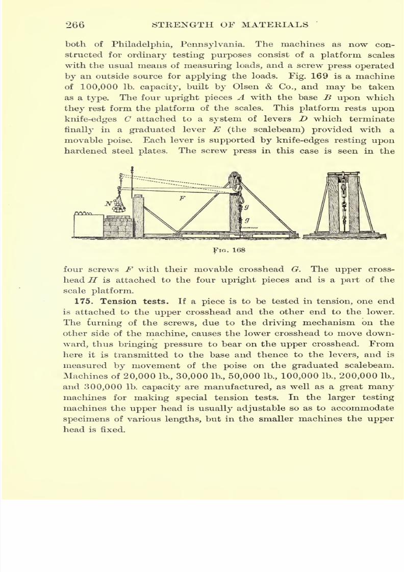
7/30/2019 Textbook on Streng 00 Slo Crich
http://slidepdf.com/reader/full/textbook-on-streng-00-slo-crich 308/433
266 STRENGTH OF MATERIALS
both of Philadelphia, Pennsylvania. The machines as now con-
structed for ordinary testing purposes consist of a platform scales
with the usual means of measuring loads, and a screw press operated
by an outside source for applying the loads. Fig. 169 is a machine
of 100,000 Ib. capacity, built by Olsen & Co., and may be taken
as a type. The four upright pieces A with the base B upon which
they rest form the platform of the scales. This platform rests upon
knife-edges C attached to a system of levers D which terminate
finally in a graduated lever E (the scalebeam) provided with a
movable poise. Each lever is supported by knife-edges resting upon
hardened steel plates. The screw press in this case is seen in the
FIG. 168
four screws F with their movable crosshead G. The upper cross-
head H is attached to the four upright pieces and is a part of the
scale platform.
175. Tension tests. If a piece is to be tested in tension, one end
is attached to the upper crosshead and the other end to the lower.
The turning of the screws, due to the driving mechanism on the
other side of the machine, causes the lower crosshead to move down-
ward, thus bringing pressure to bear on the upper crosshead. From
here it is transmitted to the base and thence to the levers, and is
measured by movement of the poise on the graduated scalebeam.
Machines of 20,000 Ib., 30,000 Ib., 50,000 Ib., 100,000 Ib., 200,000 Ib.,
and 300,000 Ib. capacity are manufactured, as well as a great many
machines for making special tension tests. In the larger testing
machines the upper head is usually adjustable so as to accommodate
specimens of various lengths, but in the smaller machines the upper
head is fixed.

7/30/2019 Textbook on Streng 00 Slo Crich
http://slidepdf.com/reader/full/textbook-on-streng-00-slo-crich 309/433
267

7/30/2019 Textbook on Streng 00 Slo Crich
http://slidepdf.com/reader/full/textbook-on-streng-00-slo-crich 310/433
7/30/2019 Textbook on Streng 00 Slo Crich
http://slidepdf.com/reader/full/textbook-on-streng-00-slo-crich 311/433
IRON AND STEEL 269
The tensile strength in pounds per square inch is computed by
dividing the load read from the scalebeam by the area of cross section
of the test specimen (seeArticle
20). Expressed as a formula,
load from scalebeamTensile strength in lb./in.
2 =area of cross section
176. Compression tests. To make compression tests the piece is
placed on a small block resting on the platform, and the lower cross-
head, provided with a similar block, is brought down upon it. The
further lowering of the crosshead compresses the specimen. The pres-
sure comes on the platform through the crossbeam that rests upon it,
and is transmitted to the scalebeam, where it is measured.
The compressive strength in lb./in.2is computed by dividing the load
in pounds as read on the scalebeam by the area of cross section of
the test specimen, as in finding the tensile strength.
177. Flexure tests. Beams are tested in flexure by mounting the
specimen on a crossbeam provided with knife-edges and applying the
load from above by means of a knife-edge attached to the under side
of the moving head. The beam is tested by lowering the moving
head as in the compression tests.
The fiber stress in the outer fiber of the beam is computed in this
case from the formula(see Article 52),
Pie
where e is the distance from the neutral axis to the outer fiber, / is
the moment of inertia with reference to the neutral axis, P is the
load in pounds as read from the scalebeam, I is the length of the span
in inches, and p is the fiber stress in lb./in.2
The maximum deflection for the concentrated central load is com-
puted by the formula(see
Article67),
where D is the deflection at the center, E the modulus of elas-
ticity (see Article8),
and P, I, and I have the same meaning as
above.
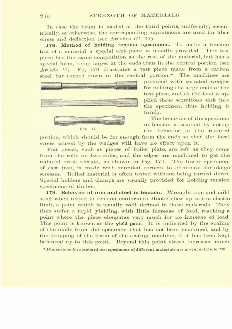
7/30/2019 Textbook on Streng 00 Slo Crich
http://slidepdf.com/reader/full/textbook-on-streng-00-slo-crich 312/433
270 STRENGTH OF MATERIALS
In case the beam is loaded at the third points, uniformly, eccen-
trically, or otherwise, the corresponding expressions are used for fiber
stress and deflection (seeArticles 52, 67).
178. Method of holding tension specimens. To make a tension
test of a material a special test piece is usually provided. This test
piece has the same composition as the rest of the material, but has a
special form, being larger at the ends than in the central portion (see
Article 20). Fig. 170 illustrates a test piece made from a carbon
steel bar turned down in the central portion.* The machines are
provided with serrated wedges
for holding the large ends of the
test piece, and as the load is ap-
plied these serrations sink into
the specimen, thus holding it
firmly.
The behavior of the specimen
in tension is studied by notingFlG>
m the behavior of the reduced
portion, which should be far enough from the ends so that the local
stress caused by the wedges will have no effect upon it.
Flat pieces, such as pieces of boiler plate, are left as they come
from the rolls on two sides, and the edges are machined to get the
reduced cross section, as shown in Fig. 171. The lower specimen,
of cast iron, is made with rounded corners to eliminate shrinkage
stresses. Eolled material is often tested without being turned down.
Special holders and clamps are usually provided for holding tension
specimens of timber.
179. Behavior of iron and steel in tension. Wrought iron and mild
steel when tested in tension conform to Hooke's law up to the elastic
limit, a point which is usually well defined in these materials. They
then suffer a rapid yielding, with little increase of load, reaching a
point where the piece elongates very much for no increase of load.
This point is known as the yield point. It is indicated by the scaling
of the oxide from the specimen that has not been machined, and by
the dropping of the beam of the testing machine, if it has been kept
balanced up to this point. Beyond this point stress increases much
* Dimensions for standard test specimens of different materials are given in Article 203.
7/30/2019 Textbook on Streng 00 Slo Crich
http://slidepdf.com/reader/full/textbook-on-streng-00-slo-crich 313/433
IRON AND STEEL 271
more slowly than deformation, untilfinally rupture is about to
occur, at which point the load attains its maximum value, called
the ultimate load. If the stress be continued, the piece begins to
neck and breaks at a load somewhat less than the maximum (see
Article7).
This necking is due to the fact that the metal under
great strain becomes plastic and flows. Brittle materials, such as
cast iron and hard steel, show very little, if any, necking. In com-
puting the fiber stress at the maximum load the original cross section
is used.
In commercial tests the load at the yield point (commercial elastic
limit) and the maximum load are noted ;also the percentage of
elongation and the percentage of reduction of cross section. The per-
centage of elongation is the increase in length divided by the original
length multiplied by 100. This percentage varies with the original
length taken (see Article 20), and therefore is usually computed for an
original length of eight inches. The percentage of reduction of cross
section is the decrease in area of the cross section divided by the
original area of the cross section multiplied by 100. In some com-
mercial laboratories provision is made for making as many as sixty
tests per hour on one machine.
180. Effect of overstrain on wrought iron and mild steel. If
wrought iron and mild steel are strained just beyond the elastic limit
in tension or compression, then released and tested again in the same
direction, it has been found that this second test shows that the
elastic limit is higher than at first, and almost as high as the load
in the first test. Eepeated overstrain of this kind, with subsequent
annealing, makes it possible to raise the elastic limit considerably
above what it was originally. When further strained the metal
loses its elasticity and takes on a permanent set;that is to say, it
does not return to its original length when the stress is removed.
The elastic properties, however, can be restored by annealing (see
Article 18). Overstrain in either tension or compression destroys
almost entirely the elasticity of the material for strain of the opposite
kind;for instance, a piece of mild steel overstrained in tension has its
elastic properties in compression almost entirely destroyed, and vice
versa. Overstraining in torsion produces much the same effect as
overstraining in tension or compression.
7/30/2019 Textbook on Streng 00 Slo Crich
http://slidepdf.com/reader/full/textbook-on-streng-00-slo-crich 314/433
272 STRENGTH OF MATERIALS
181. Relative strength of large and small test pieces. It has been
found by Tetinajer* and others that the values obtained in testing
small test pieces taken from different parts of a steel girder or I-beam
are higher than those obtained in testing the girder itself. The aver-
age of a series of tests of small test pieces gave an elastic limit of
49,000 lb./in.2and a maximum strength of 62,000 lb./in.
2Tests on
the complete girders themselves gave an elastic limit of 33,500 lb./in.2
and a maximum strength of 54,500 lb./in.2
The same has been found
true for the elastic limit of wrought-iron girders, but in this case the
maximum strength is greater in the girder than in the small test piece.
182. Strength of iron and steel at high temperatures. From a
series of tests made at Cornell University,! it was found that wrought
iron having a tensile strength of 30,000 lb./in.2
at ordinary tem-
peratures increased in strength with increase of temperature up to
475 F., and then decreased as the temperature was further raised.
Machinery steel of 60,000 lb./in.2 maximum strength gave at 475 F.
a maximum strength of 111,500 lb./iu.2
Tool steel having a strength
of 114,000 lb./in.2 at ordinary temperatures gave 145,000 lb./in.
2
maximum strength at 350 F.
Professor C. Bach also reports an elaborate series of tests on the
strength of steel at high temperatures.$ At ordinary temperatures
one bar had a maximum strength of 54,000 lb./in.2
,an elongation in
8 in. of 26.3 per cent, and a contraction of area of 46.9 per cent.
Up to a temperature of 572 F. the strength increased by about
7000 lb./in.2, and from this point fell, approximately in proportion to
the temperature, to 26,200 lb./in.2at 1022 F. The ultimate elonga-
tion decreased to 7.7 per cent at 392 F., and then increased to 39.5
per cent at 1022 F. The contraction of area fell until 392 F. was
reached, and did not rise until about 572 F.
While the tensile strength is increased for a moderately high tem-
perature, the elastic limit is lowered in proportion to the increase of
temperature, being diminished about 4 per cent for each increase of
100 F.
183. Character and appearance of the fracture. The kind and
quality of the metal are usually indicated by the character of the
*Communications, Vol. IV. f Journal Western Society of Engineers, Vol. I.
J Journal Franklin Institute, December, 1904.
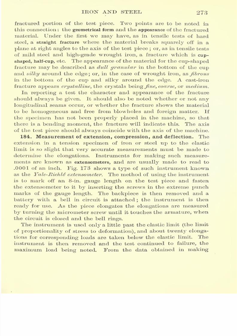
7/30/2019 Textbook on Streng 00 Slo Crich
http://slidepdf.com/reader/full/textbook-on-streng-00-slo-crich 315/433
IKON AND STEEL 273
fractured portion of the test piece. Two points are to be noted in
this connection : the geometrical form and the appearance of the fractured
material. Under the first we may have, as in tensile tests of hard
steel, a straight fracture where the material breaks squarely off in a
plane at right angles to the axis of the test piece ; or, as in tensile tests
of mild steel and high-grade wrought iron, a fracture which is cup-
shaped, half-cup, etc. The appearance of the material for the cup-shaped
fracture may be described as dull granular in the bottom of the cup
and silky around the edge ; or, in the case of wrought iron, as fibrous
in the bottom of the cup and silky around the edge. A cast-iron
fracture appears crystalline, the crystals being fine, coarse, or medium.In reporting a test the character and appearance of the fracture
should always be given. It should also be noted whether or not any
longitudinal seams occur, or whether the fracture shows the material
to be homogeneous and free from blowholes and foreign matter. If
the specimen has not been properly placed in the machine, so that
there is a bending moment, the fracture will indicate this. The axis
of the test piece should always coincide with the axis of the machine.184. Measurement of extension, compression, and deflection. The
extension in a tension specimen of iron or steel up to the elastic
limit is so slight that very accurate measurements must be made to
determine the elongations. Instruments for making such measure-
ments are known as extensometers, and are usually made to read to
.0001 of an inch. Fig. 173 shows a type of such instrument known
as the Yale-EieJile extensometer. The method of using the instrumentis to mark off an 8-in. gauge length on the test piece and fasten
the extensometer to it by inserting the screws in the extreme punch
marks of the gauge length. The backpiece is then removed and a
battery with a bell in circuit is attached;the instrument is then
ready for use. As the piece elongates the elongations are measured
by turning the micrometer screw until it touches the armature, when
the circuit is closed and the bell rings.
The instrument is used only a little past the elastic limit (the limit
ofproportionality of stress to deformation), and about twenty elonga-
tions for corresponding loads are taken below the elastic limit. The
instrument is then removed and the test continued to failure, the
maximum load being noted. From the data obtained in making
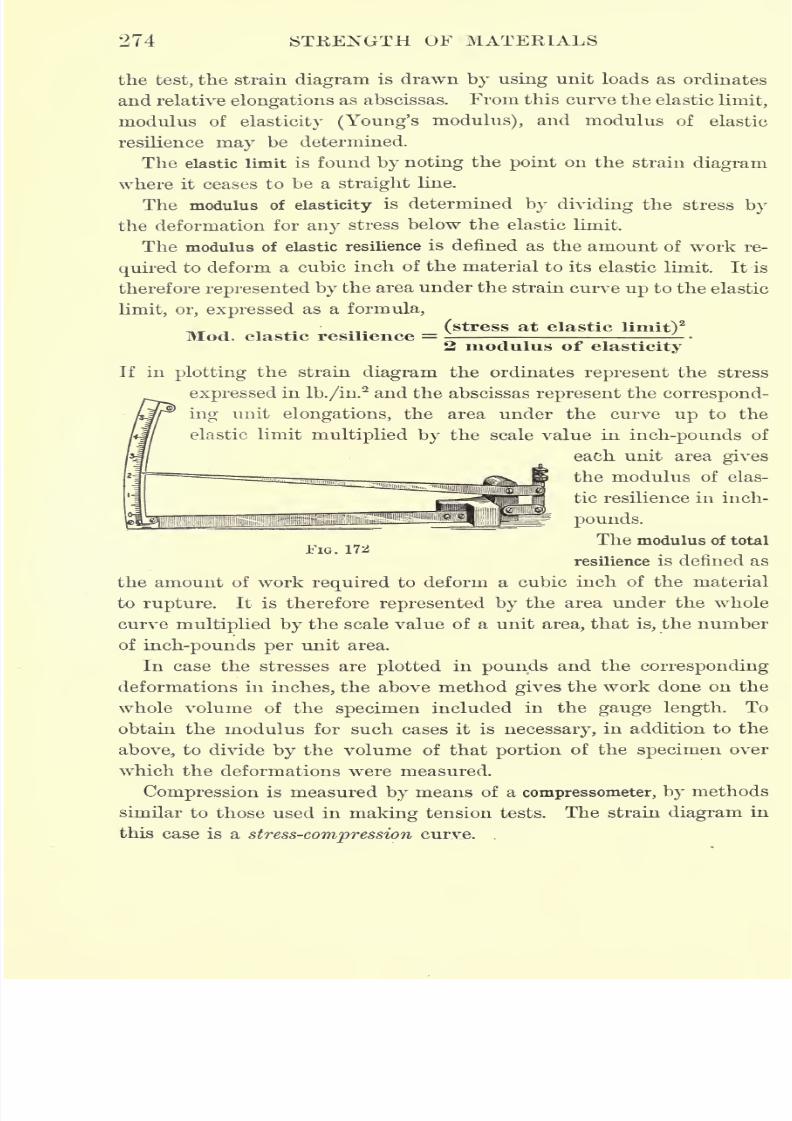
7/30/2019 Textbook on Streng 00 Slo Crich
http://slidepdf.com/reader/full/textbook-on-streng-00-slo-crich 316/433
274 STRENGTH OF MATERIALS
the test, the strain diagram is drawn by using unit loads as ordinates
and relative elongations as abscissas. From this curve the elastic limit,
modulus of elasticity (Young's modulus), and modulus of elastic
resilience may be determined.
The elastic limit is found by noting the point on the strain diagram
where it ceases to be a straight line.
The modulus of elasticity is determined by dividing the stress by
the deformation for any stress below the elastic limit.
The modulus of elastic resilience is denned as the amount of work re-
quired to deform a cubic inch of the material to its elastic limit. It is
therefore represented by the area under the strain curve up to the elastic
limit, or, expressed as a formula,
(stress at elastic limit)2
Mod. elastic resilience =2 modulus of elasticity
If in plotting the strain diagram the ordinates represent the stress
expressed in lb./in.2and the abscissas represent the correspond-
ing unit elongations, the area under the curve up to the
elastic limit multiplied by the scale value in inch-pounds of
each unit area gives
the modulus of elas-
tic resilience in inch-
pounds.
The modulus of totalFIG. 172
resilience is denned as
the amount of work required to deform a cubic inch of the material
to rupture. It is therefore represented by the area under the whole
curve multiplied by the scale value of a unit area, that is, the number
of inch-pounds per unit area.
In case the stresses are plotted in pounds and the corresponding
deformations in inches, the above method gives the work done on the
whole volume of the specimen included in the gauge length. To
obtain the modulus for such cases it is necessary, in addition to the
above, to divide by the volume of that portion of the specimen over
which the deformations were measured.
Compression is measured by means of a compressometer, by methods
similar to those used in making tension tests. The strain diagram in
this case is a stress-compression curve.
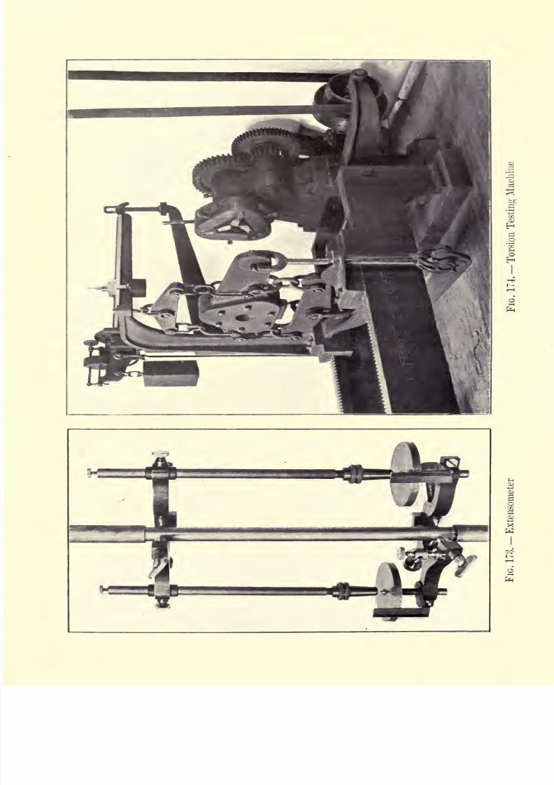
7/30/2019 Textbook on Streng 00 Slo Crich
http://slidepdf.com/reader/full/textbook-on-streng-00-slo-crich 317/433

7/30/2019 Textbook on Streng 00 Slo Crich
http://slidepdf.com/reader/full/textbook-on-streng-00-slo-crich 318/433
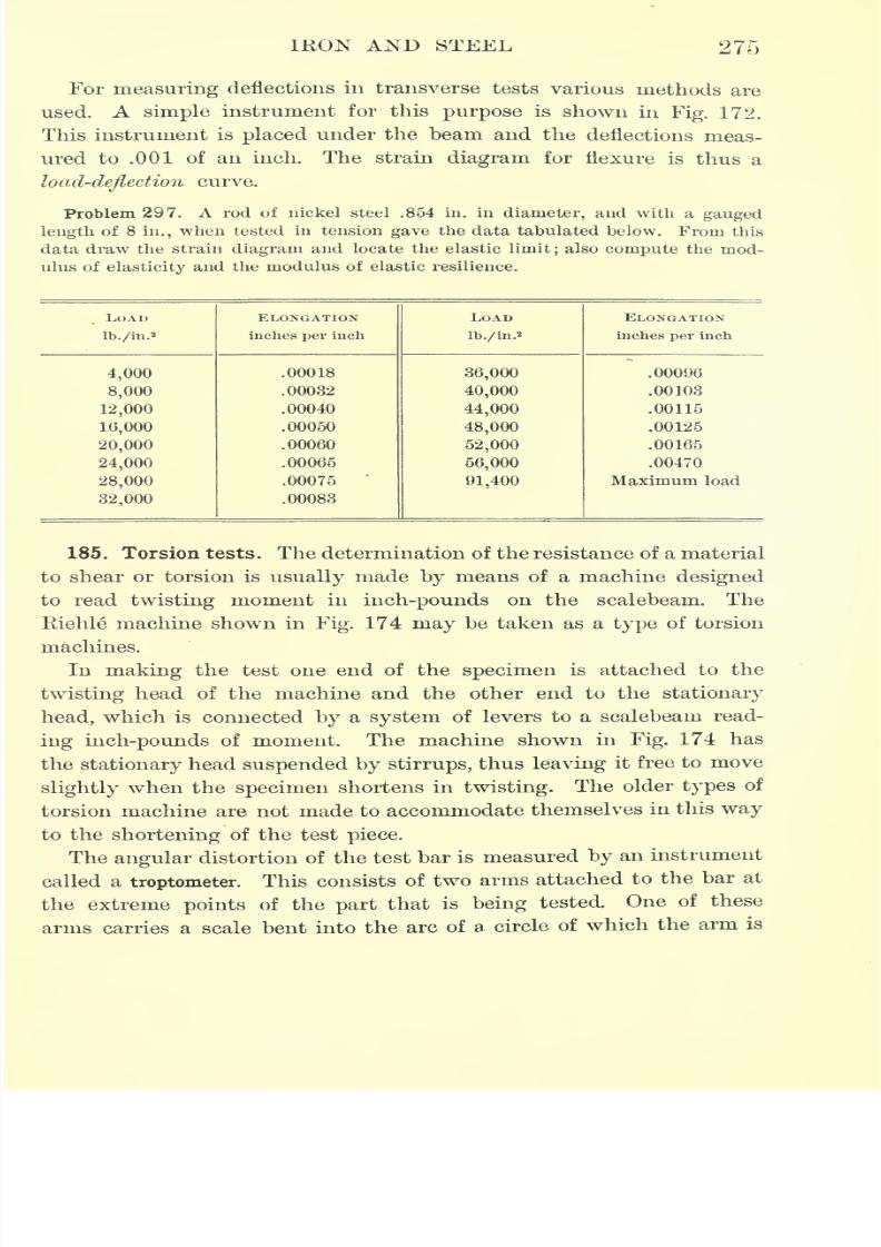
7/30/2019 Textbook on Streng 00 Slo Crich
http://slidepdf.com/reader/full/textbook-on-streng-00-slo-crich 319/433
IKON AND STEEL 275
For measuring deflections in transverse tests various methods are
used. A simple instrument for this purpose is shown inFig. 172.
This instrument is placed under the beam and the deflections meas-
ured to .001 of an inch. The strain diagram for flexure is thus a
load-deflectioncurve.
Problem 297. A rod of nickel steel .854 in. in diameter, and with a gauged
length of 8 in., when tested in tension gave the data tabulated below. From this
data draw the strain diagram and locate the elastic limit;also compute the mod-
ulus of elasticity and the modulus of elastic resilience.
LOAD
lb./in.2
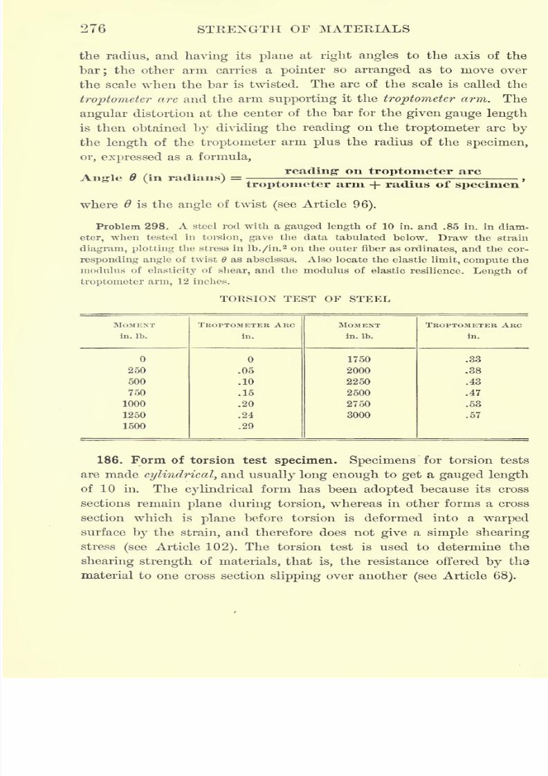
7/30/2019 Textbook on Streng 00 Slo Crich
http://slidepdf.com/reader/full/textbook-on-streng-00-slo-crich 320/433
276 STEENGTH OF MATERIALS
the radius, and having its plane at right angles to the axis of the
bar; the other arm carries a pointer so arranged as to move over
the scale when the bar is twisted. The arc of the scale is called the
troptometer arc and the arm supporting it the troptometer arm. The
angular distortion at the center of the bar for the given gauge length
is then obtained by dividing the reading on the troptometer arc by
the length of the troptometer arm plus the radius of the specimen,
or, expressed as a formula,
reading" on troptometer arcAng-le 8 (in radians) =
troptometer arm + radius of specimen
where is the angle of twist (see Article96).
Problem 298. A steel rod with a gauged length of 10 in. and .85 in. in diam-
eter, when tested in torsion, gave the data tabulated below. Draw the strain
diagram, plotting the stress in lb./in.2 on the outer fiber as ordinates, and the cor-
responding angle of twist 6 as abscissas. Also locate the elastic limit, compute the
modulus of elasticity of shear, and the modulus of elastic resilience. Length of
troptometer arm, 12 inches.
TORSION TEST OF STEEL
MOMENT
in. Ib.
7/30/2019 Textbook on Streng 00 Slo Crich
http://slidepdf.com/reader/full/textbook-on-streng-00-slo-crich 321/433
IKON AND STEEL 277
When torsion tests are made, the moment in in. Ib. is read from
the machine, and the shearing stress in the outer fiber in lb./in.2is
computed from the formula,
p
where Pa is the twisting moment read from the machine, r the
radius of the test piece, and Ipthe polar moment of inertia of the
cross section.*
The modulus of elasticity in shear is computed from the relation,
where Pa and Ipare defined as above, I is the gauged length in inches,
and is the angle of twist in radians.
The test piece is held in position by a set of adjustable jaws similar
to those used in ordinary pipe wrenches. The gauged length should
be taken far enough from the ends so that the local stress due to the
jaws maynot influence the results.
187. Torsion as a test of shear. Although the torsion test is used
to determine the shearing strength of materials, it is not an accurate
test, since the shearing stress is a maximum on the outer elements,
and zero at the center. For this reason the inner material tends to
reenforce the outer, thus giving a higher shearing strength than
would otherwise be obtained. A more perfect torsion test would be
one madeupon
a hollow tube of thematerial,
for in this case the
inner reenforcing core would not be present. However, the difficulty
of obtaining suitable hollow tubes for test pieces makes their use
impracticable for ordinary tests.
A further objection to the torsion test as a test of shearing strength
lies in the fact that there is considerable tension in the outer ele-
ments of the test piece during the test. Any element of the cylin-
drical test
piecewhich is a
straightline before the strain becomes a
helix during the test. Since the length of the helix is greater than
that of the original element, a tensile stress is thus produced in the
outer fibers. In fact, in testing wrought iron in torsion the outer
fibers often fail in tension along the helix. The slight shortening
TTr4
* For a cylinder, Ip =
7/30/2019 Textbook on Streng 00 Slo Crich
http://slidepdf.com/reader/full/textbook-on-streng-00-slo-crich 322/433
278 STRENGTH OF MATERIALS
of the whole specimen, due to the twisting, is corrected in part by
the swinging head of the machine shown in Fig. 174.
188. Shearing tests. To determine the shearing strength of timber
along the grain and the resistance of iron and steel to the pulling out
of rivets, many special tests are used. By means of a special piece of
apparatus, the force required to push off, along the grain, a projecting
piece from a test piece of timber is easily measured on the ordi-
nary tension-compression machine. The intensity of shearing stress is
computed by dividing the load by the area of the block pushed off.
Tests are also made on wrought-iron plates to determine the force
required to pull out a rivet through the metal, both in the direction
of the fiber and perpendicular to it. A series of such tests may be
found in the Watertown Arsenal Report for 1882. Many tests have
also been made to determine the shearing strength of rivets.
189. Impact tests. In actual service many materials are subjected
to shock or impact (see Article 74).This is especially true of all
railway structural material, such as rails, axles, springs, couplers,
bolsters, wheels, etc., which must be designed to withstand consid-
erable shock. Two special machines have been designed to test
materials in impact. The first, called the drop testing machine, is
operated by allowing a given weight (hammer) to drop a given dis-
tance upon a test piece mounted on an anvil under the hammer.
The other form of machine is operated by allowing a heavy pendu-
lum to strike the specimen when placed in the center of its swing.
In either case the amount of the energy of the blow absorbed by the
specimen is desired.
The results obtained from impact tests can only be comparative in
any case, since a part of the energy of the blow must be absorbed
by the parts of the machine itself. This is seen in the drop testing
machine in the absorption of energy by the anvil and hammer.
Since the results of such tests cannot be absolute, it is highly
necessary that they should be standardized by making tests on the same
anvil with the same hammer. The Master Car Builders Association
has taken a step toward such standardization by building an impact
testing machine for testing materials used by them. This machine
has been established at Purdue University. Its maximum blow is
given by a hammer having a weight of 1640 lb., and dropping 50 ft.
7/30/2019 Textbook on Streng 00 Slo Crich
http://slidepdf.com/reader/full/textbook-on-streng-00-slo-crich 323/433
IRON AND STEEL 279
The use of this machine should do much to standardize specifications
for railway material.*
Tests in impact compression, impact tension, and impact flexure
are also made, but on account of the uncertainty as to the amount of
energy absorbed by the test specimen many engineers do not favor
such tests. Many of these objections, however, might be removed by
proper standardization.
Some recent investigations seem to indicate that the impact test
shows very little that cannot be determined by static tests.
190. Cold bending tests. Cold bending tests are tests of the duc-
tility of metals, and are designed to show the effect on the metal of
being bent in various ways while cold. Such material as rivet steel
and Bessemer steel bridge pieces are bent double over a pin of speci-
fied radius, and the result noted. In making these tests the angle at
which the first crack occurs and the angle at wrhich rupture occurs
are read.
Few machines for making cold bending tests have been made.
The tests are usually made by bending the specimen over the edge
of a vise, or some such simple device, according to specifications. The
tests have never been standardized, but their importance is obvious,
since the conditions of actual service are thus applied to the specimen.
191. Cast iron. Pig iron is a combination of iron with small
percentages of carbon, silicon, sulphur, phosphorus, and manganese,
obtained from the blast furnace. The carbon probably comes from
the fuel used in reducing the ore;the other impurities come either
from the ore or from the flux. The product is graded, according to
chemical composition, into forge pig and foundry pig. Foundry pig
is remelted in a cupola furnace and made into castings of various
kinds; forge pig is used in making wrought iron.
Cast iron is a very brittle material, weak in tension and strong in
compression. Its great usefulness in engineering structures comes
from the fact that it may be readily molded into any desired form;
it is, however, being replaced by the various steel products. The
carbon, silicon, and other impurities contained in the iron affect its
physical properties.
* For a description of this machine see the report by Professor W. F. M. Goss, Proc.
Amer. Soc. for Testing Materials, 1903.
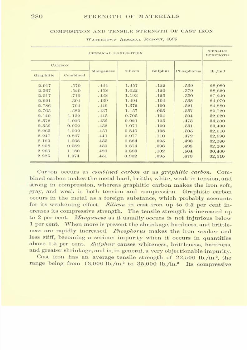
7/30/2019 Textbook on Streng 00 Slo Crich
http://slidepdf.com/reader/full/textbook-on-streng-00-slo-crich 324/433
280 STRENGTH OF MATERIALS
COMPOSITION AND TENSILE STRENGTH OF CAST IRON
WATERTOWN ARSENAL REPORT, 1895
CHEMICAL COMPOSITION
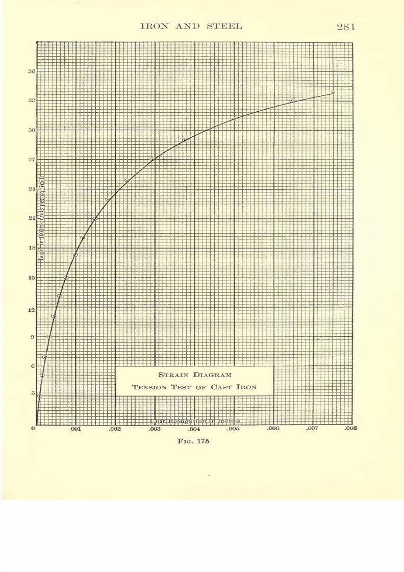
7/30/2019 Textbook on Streng 00 Slo Crich
http://slidepdf.com/reader/full/textbook-on-streng-00-slo-crich 325/433
IKON AND STEEL 281
36
r,
30
24
21
18
15
12
STRAIN DIAGRAM
TENSION TEST OF CAST IRON
.001 .002 .003 .004 .005 .006 .007 .008
FIG. 175
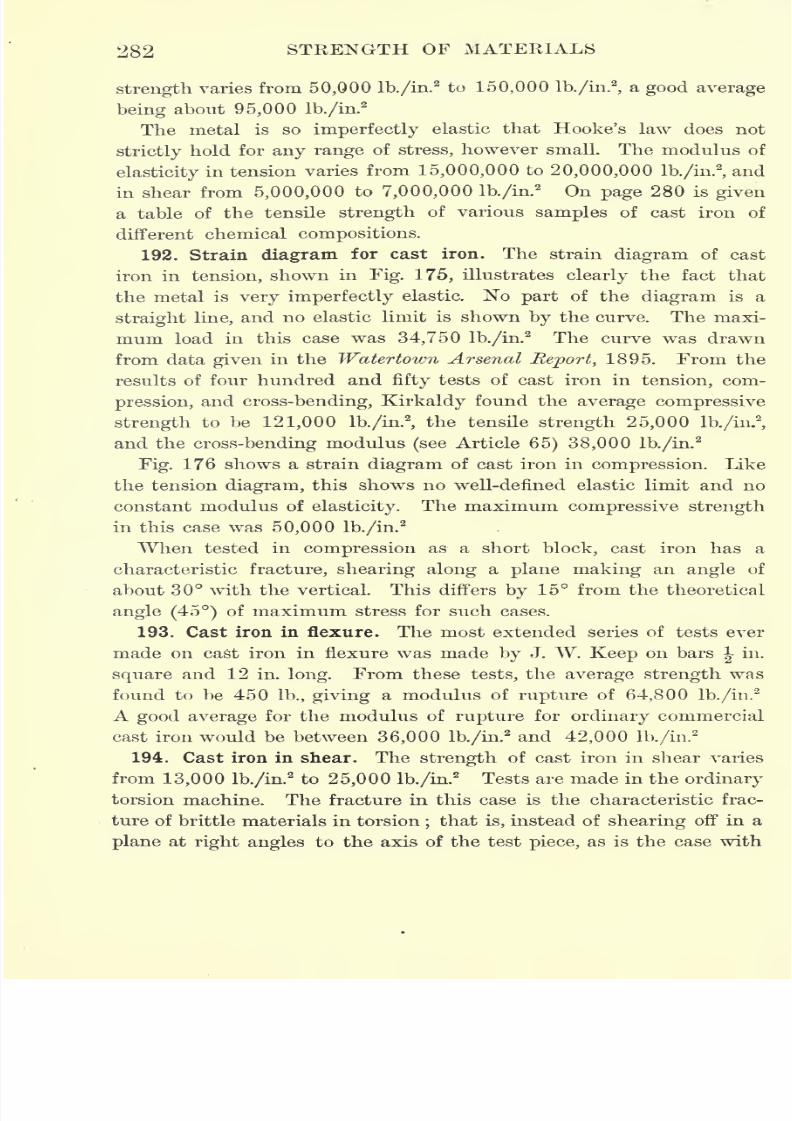
7/30/2019 Textbook on Streng 00 Slo Crich
http://slidepdf.com/reader/full/textbook-on-streng-00-slo-crich 326/433
282 STRENGTH OF MATERIALS
strength varies from 50,000 lb./in.2to 150,000 lb./in.
2
,a good average
being about 95,000 lb./in.2
The metal is so imperfectly elastic that Hooke's law does not
strictly hold for any range of stress, however small. The modulus of
elasticity in tension varies from 15,000,000 to 20,000,000 lb./in.2
,and
in shear from 5,000,000 to 7,000,000 lb./in.2 On page 280 is given
a table of the tensile strength of various samples of cast iron of
different chemical compositions.
192. Strain diagram for cast iron. The strain diagram of cast
iron in tension, shown in Fig. 175, illustrates clearly the fact that
the metal is very imperfectly elastic. No part of the diagram is a
straight line, and no elastic limit is shown by the curve. The maxi-
mum load in this case was 34,750 lb./in.2
The curve was drawn
from data given in the Watertown Arsenal Report, 1895. From the
results of four hundred and fifty tests of cast iron in tension, com-
pression, and cross-bending, Kirkaldy found the average compressive
strength to be 121,000 lb./in.2
,the tensile strength 25,000 lb./in.
2
,
and the cross-bending modulus (see Article 65) 38,000 lb./in.2
Fig. 176 shows a strain diagram of cast iron in compression. Like
the tension diagram, this shows no well-defined elastic limit and no
constant modulus of elasticity. The maximum compressive strength
in this case was 50,000 lb./in.2
When tested in compression as a short block, cast iron has a
characteristic fracture, shearing along a plane making an angle of
about 30 with the vertical. This differs by 15 from the theoretical
angle (45) of maximum stress for such cases.
193. Cast iron in flexure. The most extended series of tests ever
made on cast iron in flexure was made by J. W. Keep on barsJ-
in.
square and 12 in. long. From these tests, the average strength was
found to be 450 lb., giving a modulus of rupture of 64,800 lb./in.'2
A good average for the modulus of rupture for ordinary commercial
cast iron would be between 36,000 lb./in.2 and 42,000 lb./in.
2
194. Cast iron in shear. The strength of cast iron in shear varies
from 13,000 lb./in.2to 25,000 lb./in.
2Tests are made in the ordinary
torsion machine. The fracture in this case is the characteristic frac-
ture of brittle materials in torsion;that is, instead of shearing off in a
plane at right angles to the axis of the test piece, as is the case with
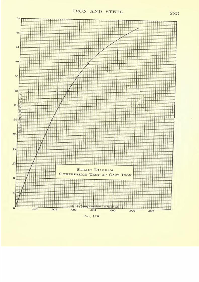
7/30/2019 Textbook on Streng 00 Slo Crich
http://slidepdf.com/reader/full/textbook-on-streng-00-slo-crich 327/433
IRON AND STEEL283
STRAIN DIAGRAM
COMPRESSION TEST OF CAST IRON
,007
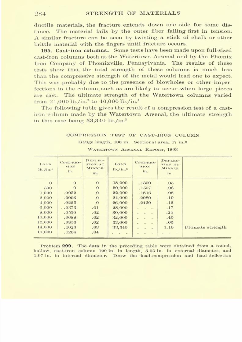
7/30/2019 Textbook on Streng 00 Slo Crich
http://slidepdf.com/reader/full/textbook-on-streng-00-slo-crich 328/433
284 STRENGTH OF MATERIALS
ductile materials, the fracture extends down one side for some dis-
tance. The material fails by the outer fiber failing first in tension.
A similar fracture can be seen by twisting a stick of chalk or other
brittle material with the fingers until fracture occurs.
195. Cast-iron columns. Some tests have been made upon full-sized
cast-iron columns both at the Watertown Arsenal and by the Phoenix
Iron Company of Phoenixville, Pennsylvania. The results of these
tests show that the total strength of these columns is much less
than the compressive strength of the metal would lead one to expect.
This was probably due to the presence of blowholes or other imper-
fections in the column, such as are likely to occur when large pieces
are cast. The ultimate strength of the Watertown columns varied
from 21,0001b./in.2to 40,000 lb./in.
2
The following table gives the result of a compression test of a cast-
iron column made by the Watertown Arsenal, the ultimate strength
in this case being 33,340 lb./in.2
COMPRESSION TEST OF CAST-IRON COLUMN
Gauge length, 100 in. Sectional area, 17 in. 2
WATERTOWN ARSENAL REPORT, 1893
LOAD
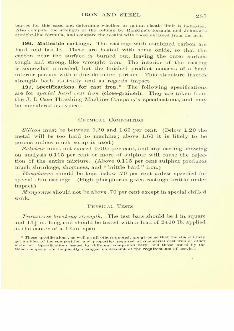
7/30/2019 Textbook on Streng 00 Slo Crich
http://slidepdf.com/reader/full/textbook-on-streng-00-slo-crich 329/433
IKON AND STEEL 285
curves for this case, and determine whether or not an elastic limit is indicated.
Also compute the strength of the column by Rankine's formula and Johnson's
straight-line formula, and compare the results with those obtained from the test.
196. Malleable castings. The castings with combined carbon are
hard and brittle. These are heated with some oxide, so that the
carbon near the surface is burned out, leaving the outer surface
tough and strong, like wrought iron. The interior of the casting
is somewhat annealed, but the finished product consists of a hard
interior portion with a ductile outer portion. This structure insures
strength both statically and as regards impact.
197. Specifications for cast iron.* The following specifications
are for special hard cast iron(close-grained). They are taken from
the J. I. Case Threshing Machine Company's specifications, and maybe considered as typical.
CHEMICAL COMPOSITION
Silicon must be between 1.20 and 1.60 per cent. (Below 1.20 the
metal will be too hard to machine;above 1.60 it is likely to be
porous unless much scrap is used.)
Sulphur must not exceed 0.095 per cent, and any casting showing
on analysis 0.115 per cent or more of sulphur will cause the rejec-
tion of the entire mixture. (Above 0.115 per cent sulphur produces
much shrinkage, shortness, and "brittle hard
"
iron.)
Phosphorus should be kept below .70 per cent unless specified for
special thin castings. (High phosphorus gives castings brittle under
impact.)
Manganese should not be above .70 per cent except in special chilled
work.
PHYSICAL TESTS
Transverse breaking strength. The test bars should be 1 in. square
and13^
in. long, and should be tested with a load of 2400 Ib. applied
at the center of a 12-in. span.
* These specifications, as well as all others quoted, are given so that the student may
get an idea of the composition and properties required of commerial cast iron or other
material. Specifications issued by different companies vary, and those issued by the
game company are frequently changed on account of the requirements of service.
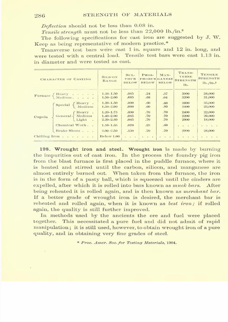
7/30/2019 Textbook on Streng 00 Slo Crich
http://slidepdf.com/reader/full/textbook-on-streng-00-slo-crich 330/433
286 STEENGTH OF MATERIALS
Deflection should not be less than 0.08 in.
Tensile strength must not be less than 22,000 lb./in.2
The following specificationsfor cast iron are suggested by J. W.
Keep as being representativeof modern practice.*
Transverse test bars were cast 1 in. square and 12 in. long, and
were tested with a central load. Tensile test bars were cast 1.13 in.
in diameter and were tested as cast.
CHARACTER OF CASTING
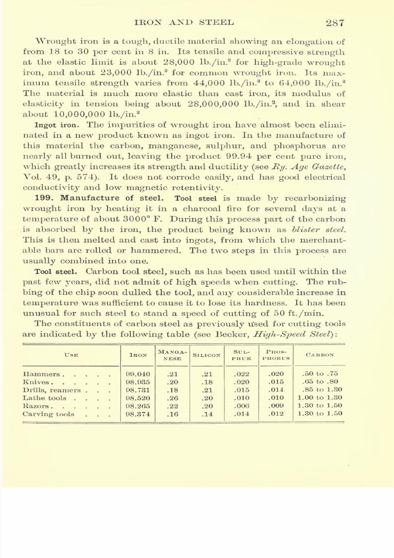
7/30/2019 Textbook on Streng 00 Slo Crich
http://slidepdf.com/reader/full/textbook-on-streng-00-slo-crich 331/433
IRON AND STEEL 287
Wrought iron is a tough, ductile material showing an elongation of
from 18 to 30 per cent in 8 in. Its tensile and compressive strength
at the elastic limit is about 28,000 lb./in.2for high-grade wrought
iron, and about 23,000 lb./in.2
for common wrought iron. Its max-
imum tensile strength varies from 44,000 lb./in.2to 64,000 lb./in.
2
The material is much more elastic than cast iron, its modulus of
elasticity in tension being about 28,000,000 lb./in.2,and in shear
about 10,000,000 lb./in.2
Ingot iron. The impurities of wrought iron have almost been elimi-
nated in a new product known as ingot iron. In the manufacture of
this material the carbon, manganese, sulphur, and phosphorus are
nearly all burned out, leaving the product 99.94 per cent pure iron,
which greatly increases its strength and ductility (see Ey. Age Gazette,
Vol. 49, p. 574). It does not corrode easily,and has good electrical
conductivity and low magnetic retentivity.
199. Manufacture of steel. Tool steel is made by recarbonizing
wrought iron by heating it in a charcoal fire for several days at a
temperature of about 3000 F. During this process part of the carbon
is absorbed by the iron, the product being known as Ulster steel.
This is then melted and cast into ingots, from which the merchant-
able bars are rolled or hammered. The two steps in this process are
usually combined into one.
Tool steel. Carbon tool steel, such as has been used until within the
past few years, did not admit of high speeds when cutting. The rub-
bing of the chip soon dulled the tool, and any considerable increase in
temperature was sufficient to cause it to lose its hardness. It has been
unusual for such steel to stand a speed of cutting of 50 ft./min.
The constituents of carbon steel as previously used for cutting tools
are indicated by the following table (see Becker, High-Speed Steel):
USE
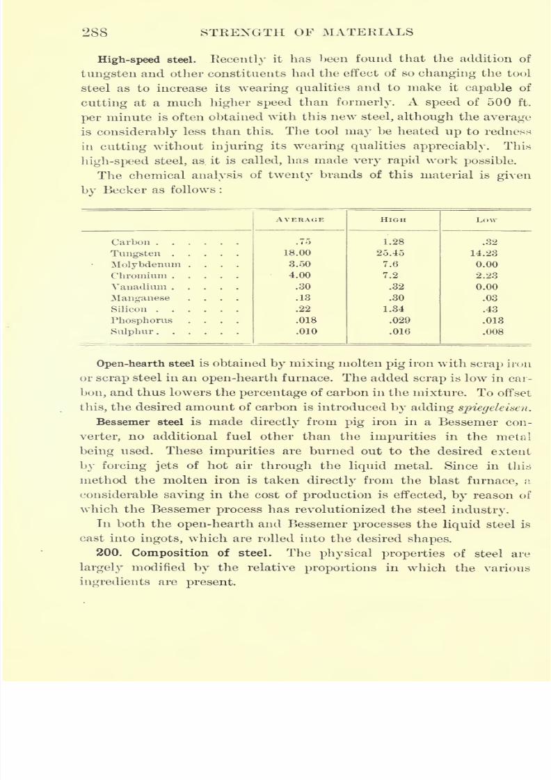
7/30/2019 Textbook on Streng 00 Slo Crich
http://slidepdf.com/reader/full/textbook-on-streng-00-slo-crich 332/433
288 STRENGTH OF MATERIALS
High-speed steel. Recently it has been found that the addition of
tungsten and other constituents had the effect of so changing the tool
steel as to increase its wearing qualities and to make it capable of
cutting at a much higher speed than formerly. A speed of 500 ft.
per minute is often obtained with this new steel, although the average
is considerably less than this. The tool may be heated up to redness
in cutting without injuring its wearing qualities appreciably. This
high-speed steel, as. it is called, has made very rapid work possible.
The chemical analysis of twenty brands of this material is given
by Becker as follows :
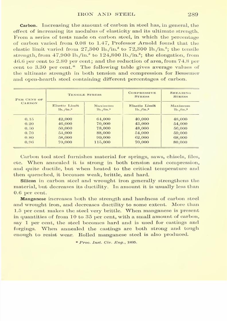
7/30/2019 Textbook on Streng 00 Slo Crich
http://slidepdf.com/reader/full/textbook-on-streng-00-slo-crich 333/433
IRON AND STEEL 289
Carbon. Increasing the amount of carbon in steel has, in general, the
effect of increasing its modulus of elasticity and its ultimate strength.
From a series of tests made on carbon steel, in which the percentage
of carbon varied from 0.08 to 1.47, Professor Arnold found that the
elastic limit varied from 27,300 lb./in.2to 72,300 lb./in.
2
;the tensile
strength, from 47,900 lb./in.'2to 124,800 lb./in.
2
;the elongation, from
46.6 per cent to 2.80 per cent; and the reduction of area, from 74.8per-
cent to 3.30 per cent* The following table gives average values of
the ultimate strength in both tension and compression for Bessemer
and open-hearth steel containing different percentages of carbon.
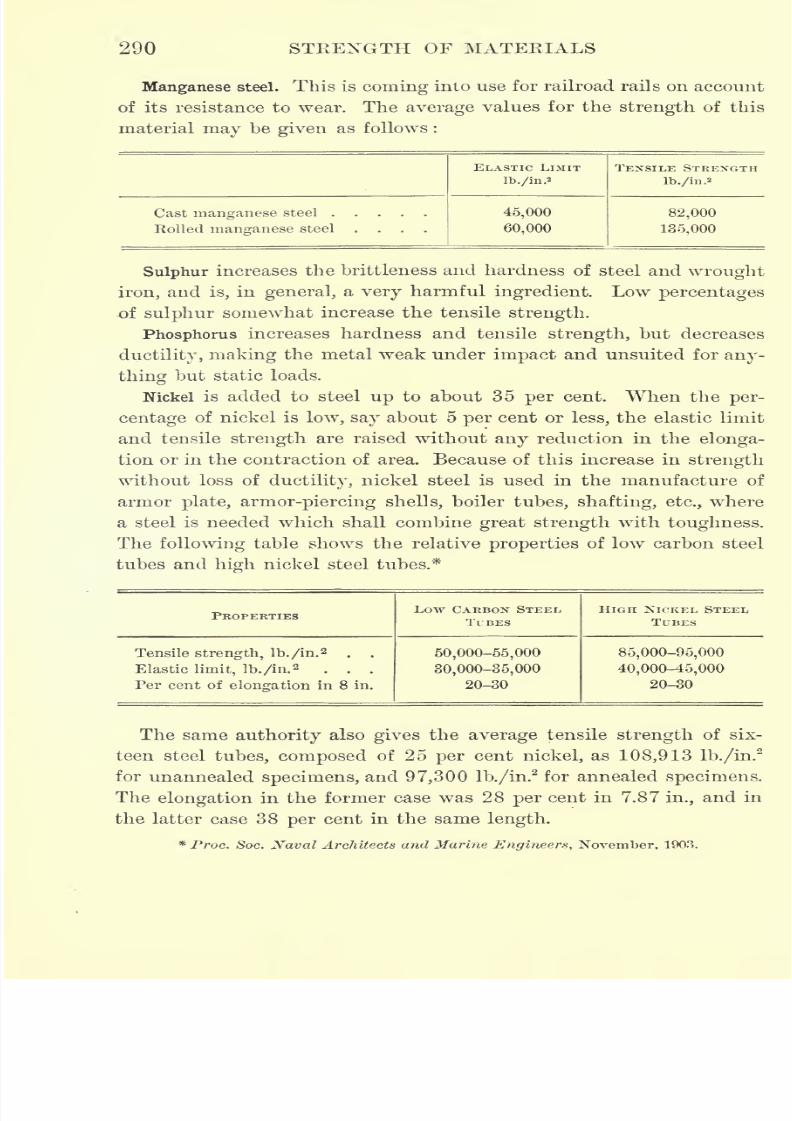
7/30/2019 Textbook on Streng 00 Slo Crich
http://slidepdf.com/reader/full/textbook-on-streng-00-slo-crich 334/433
290 STRENGTH OF MATERIALS
Manganese steel. This is coming into use for railroad rails on account
of its resistance to wear. The average values for the strength of this
material may be given as follows :
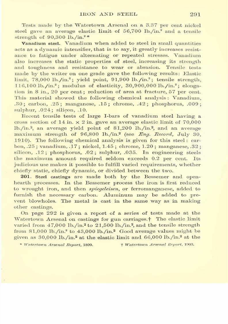
7/30/2019 Textbook on Streng 00 Slo Crich
http://slidepdf.com/reader/full/textbook-on-streng-00-slo-crich 335/433
IRON AND STEEL 291
Tests made by the Watertown Arsenal on a 3.37 per cent nickel
steel gave an average elastic limit of 56,700 lb./in.2and a tensile
strength of 90,300 lb./in.2 *
Vanadium steel. Vanadium when added to steel in small quantities
acts as a dynamic intensifier, that is to say, it greatly increases resist-
ance to fatigue under alternating or repeated stresses. Vanadium
also increases the static properties of steel, increasing its strength
and toughness and resistance to wear or abrasion. Tensile tests
made by the writer on one grade gave the following results: Elastic
limit, 78,000 lb./in.2
; yield point, 91,900 lb./in.2
;tensile strength,
116,100 lb./in.2
;modulus of elasticity, 30,900,000 lb./in.
2
; elonga-
tion in 8 in., 20 per cent; reduction of area at fracture, 57 per cent.
This material showed the following chemical analysis : Vanadium,
.30; carbon, .25; manganese, .15; chrome, .42; phosphorus, .009;
sulphur, .024; silicon, .10.
Recent tensile tests of large I-bars of vanadium steel having a
cross section of 14 in. x 2 in. gave an average elastic limit of 70,000
lb./in.2
,an average yield point of 81,200 lb./in.
2,and an average
maximum strength of 96,800 lb./in.2
(see Eng. Record, July 30,
1910). The following chemical analysis is given for this steel: car-
bon, .25; vanadium, .17
; nickel, 1.45; chrome, 1.20
; manganese, .32;
silicon, .12; phosphorus, .02; sulphur, .035. In engineering steels
the maximum amount required seldom exceeds 0.2 per cent. Its
judicious use makes it possible to fulfill varied requirements, whether
chiefly static, chiefly dynamic, or divided between the two.
201. Steel castings are made both by the Bessemer and open-
hearth processes. In the Bessemer process the iron is first reduced
to wrought iron, and then spiegeleisen, or ferromanganese, added to
furnish the necessary carbon. Aluminum may be added to pre-
vent blowholes. The metal is cast in the same way as in making
other castings.
On page 292 is given a report of a series of tests made at the
Watertown Arsenal on castings for gun carriages.! The elastic limit
varied from 47,000 lb./in.2 to 21,500 lb./in.
2,and the tensile strength
from 81,000 lb./in.2to 43,000 lb./in.
2 Good average values might be
given as 30,000 lb./in.2at the elastic limit and 66,000 lb./in.
2 at the
* Watertown Arsenal Report, 1899. t Watertown Arsenal Report, 1903.
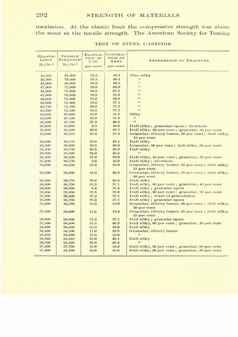
7/30/2019 Textbook on Streng 00 Slo Crich
http://slidepdf.com/reader/full/textbook-on-streng-00-slo-crich 336/433
292 STRENGTH OF MATERIALS
maximum. At the elastic limit the compressive strength was about
the same as the tensile strength. The American Society for Testing
TEST OF STEEL CASTINGS
ELASTICIJMIT
lb./in.
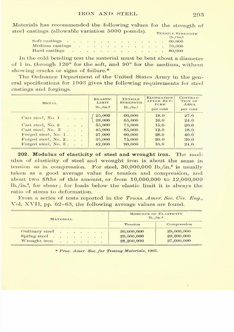
7/30/2019 Textbook on Streng 00 Slo Crich
http://slidepdf.com/reader/full/textbook-on-streng-00-slo-crich 337/433
IRON AND STEEL 293
Materials has recommended the following values for the strength of
steel castings (allowable variation 5000 pounds). TENSILF STRENGTH
lb./in.2
Softcastings 60,000Medium castings 70,000
Hard castings 80,000
In the cold bending test the material must be bent about a diameter
of 1 iii. through 120 for the soft, and 90 for the medium, without
showing cracks or signs of failure.*
The Ordnance Department of the United States Army in the gen-
eral specifications for 1903 gives the following requirements for steel
castings and forgings.
METAL
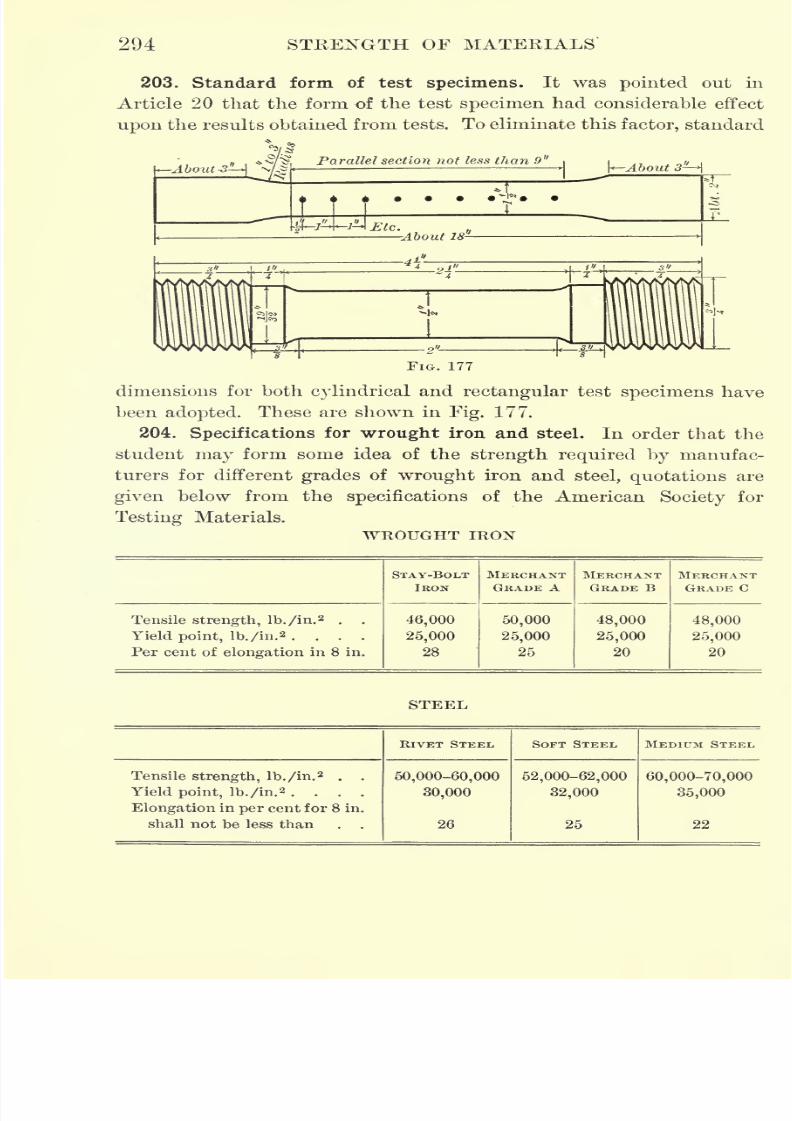
7/30/2019 Textbook on Streng 00 Slo Crich
http://slidepdf.com/reader/full/textbook-on-streng-00-slo-crich 338/433
294 STRENGTH OF MATERIALS
203. Standard form of test specimens. It was pointed out in
Article 20 that the form of the test specimen had considerable effect
upon the results obtained from tests. To eliminate this factor, standard
*/About -3 A N/.g
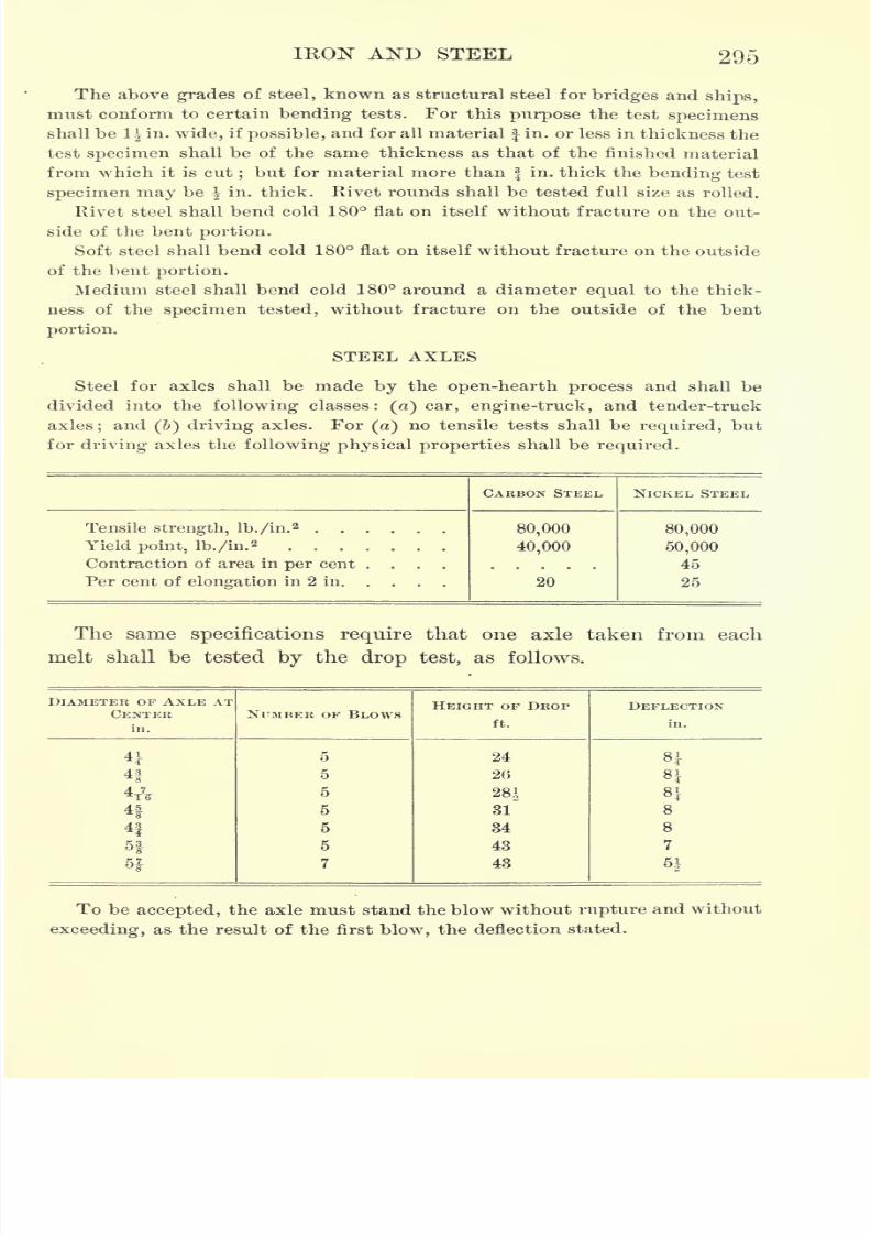
7/30/2019 Textbook on Streng 00 Slo Crich
http://slidepdf.com/reader/full/textbook-on-streng-00-slo-crich 339/433
IKON AND STEEL 295
The above grades of steel, known as structural steel for bridges and ships,
must conform to certain bending tests. For this purpose the test specimens
shall be 1| in. wide, if possible, and for all material f in. or less in thickness the
test
specimenshall be of the same thickness as that of the finished material
from which it is cut;but for material more than in. thick the bending test
specimen may be \ in. thick. Rivet rounds shall be tested full size as rolled.
Rivet steel shall bend cold 180 flat on itself without fracture on the out-
side of the bent portion.
Soft steel shall bend cold 180 flat on itself without fracture on the outside
of the bent portion.
Medium steel shall bend cold 180 around a diameter equal to the thick-
ness of the specimen tested, without fracture on the outside of the bent
portion.
STEEL AXLES
Steel for axles shall be made by the open-hearth process and shall be
divided into the following classes :
(a) car, engine-truck, and tender-truck
axles;and (J) driving axles. For (a) no tensile tests shall be required, but
for driving axles the following physical properties shall be required.
7/30/2019 Textbook on Streng 00 Slo Crich
http://slidepdf.com/reader/full/textbook-on-streng-00-slo-crich 340/433
296 STRENGTH OF MATERIALS
DESCRIPTION OF THE DROP TEST
The points of support on which the axle rests during tests shall be 3 ft.
apart from center to center; the hammer must weigh 1640 Ib.;the anvil,
which is supported on springs, must weigh 17,500 Ib.;
it must be free to
move in a vertical direction;the springs upon which it rests must be twelve
in number, of the kind specified ;and the radius of supports and of the strik-
ing face on the hammer in the direction of the axis of the axle must be 5 in.
The deflections are measured by placing a straightedge along the
axle, properly held at the supports, and measuring the distance from
this
straightedge
to the axle both before and after the blow. The
difference between the two measurements gives the deflection.
7/30/2019 Textbook on Streng 00 Slo Crich
http://slidepdf.com/reader/full/textbook-on-streng-00-slo-crich 341/433
CHAPTER XIII
LIME, CEMENT, AND CONCRETE
205. Quicklime. If calcium carbonate (ordinary limestone) is
heated to about 800 F., carbon dioxide is driven off, leaving an
oxide of calcium, which is known as quicklime. This has a great
affinity for water and slacks upon exposure to moisture. Slacked
lime when dry falls into a fine powder.
Lime mortar is formed by mixing slacked lime with a large propor-
tion of sand. Upon exposure to the air this mortar becomes hard by
reason of the lime combining with carbon dioxide and forming again
calcium carbonate, the product being a sandy limestone. Lime mortar
is used in laying brick walls and in structures where the mortar will
not be exposed to water, since it will not set, i.e. combine with carbon
dioxide, under water.
206. Cement. When limestone contains a considerable amount of
clay, the lime produced is called hydraulic lime, for the reason that
mortar made by using it will harden under water. If the limestone
contains about 30 per cent of clay and is heated to 1000 F., the
carbon dioxide is driven off, and the resulting product, when finely
ground, is called natural cement. When about 25 per cent of water is
added, this cement hardens, because of the formation of crystals of
calcium and aluminum compounds.
If Limestone and clay are mixed in the proper proportions, usually
about three parts of lime carbonate to one of clay, and the mixture
roasted to a clinker by raising it to a temperature approaching 3000 F.,
the product, when ground to a fine powder, is known as Portland cement
The proper proportion of limestone and clay is determined by find-
ing the proportions of the particular clay and stone that will make
perfect crystallization possible. In the case of natural cement the
lime and clay are not present in such proportionsas to form perfect
crystals, and consequently it i^ not as strong as Portland cement.
297
7/30/2019 Textbook on Streng 00 Slo Crich
http://slidepdf.com/reader/full/textbook-on-streng-00-slo-crich 342/433
298 STRENGTH OF MATERIALS
The artificial mixing of the limestone and clay in the manufacture
of Portland cement is accomplished in different ways. Throughout
the north central portion of the United States large beds of marl are
found, and also in the same localities beds of suitable clay. This marl
is nearly pure limestone, and is mixed with the clay wet. (These
materials are also mixed dry.) Both the marl and clay are pumped to
the mixer, where they are mixed in the proper proportions. The prod-
uct is then dried, roasted, and ground. Most American Portland ce-
ments, however, are made by grinding a clay-bearing limestone with
sufficient pure limestone to give the proper proportions. After being
thoroughly mixed the product is roasted and ground to a powder.
Slag cement (Puzzolan) is made by thoroughly mixing the granulated
slag from an iron blast furnace with slacked lime, and then grinding
the mixture to a fine powder. Slag cements are usually lighter in
color than the Portland cements, and have a lower specific gravity, the
latter ranging from 2.7 to 2.8. They are also somewhat slower in
setting than the Portland cements, and have a slightly lower tensile
strength. They are not adapted to resist mechanical wear, such as
would be necessary in pavements and floors, but are suitable for
foundations or any work not exposed to dry air or great strain.
True Portland cement may be made from a mixture of blast-furnace
slag and finely powdered limestone, the mixture being burned in a
kiln and the resultant clinker ground to powder. Both the Portland
and the Puzzolan cements will set under water, i.e. they are hydraulic.
207. Cement tests. The many different processes of mixing, roast-
ing, grinding, and setting through which a cement must pass, require
that a number of tests be made to determine whether or not these
have been well done. If the grinding has been improperly done, or
if any of the other operations of manufacture have been neglected,
the product may be very weak, or even worthless. To make sure that
all the steps in the manufacture of the cement have been properly
carried out, engineers make use of the following tests : (a) test of
soundness; (6)
test of fineness; (c)
test of time of setting ; (d)test
of tensile strength.
208. Test of soundness. One test for soundness consists in boiling
a small ball of neat cement in water for three hours, and noting
whether or not checks or cracks occur. If the cement contains too
7/30/2019 Textbook on Streng 00 Slo Crich
http://slidepdf.com/reader/full/textbook-on-streng-00-slo-crich 343/433
LIME, CEMENT, AND CONCRETE 299
much free lime, the ball will disintegrate and show signs of crumbling.
The ball of cement is kept under a damp cloth for twenty-four
hours before boiling. This test is not regarded with favor by many
engineers (see steam pat test, specifications, p. 305).
209. Test of fineness. If the grinding has not been properly done,
large particles of clinker remain, which act as a sand or other foreign
substance and thus weaken the cement. The test for fineness is made
by sifting the cement through different sieves; usually all of it is
required to pass through a sieve of 50 meshes to the inch, and a
smaller amount through sieves of 80 and 100 meshes. About 75 per
cent should pass through a 200-mesh sieve (see Article 214).
210. Test of time of setting. It is important that a cement should
not set too quickly or too slowly. A test for time of setting, known
as Grillmore's test, has been standardized in the United States, and
consists in applying to a small cement pat given weights supported
by points of specified area(Fig. 178). The cement pat is made by
mixing a portion of neat cement with the proper amount of water,
mounting this on a piece of glass, and smoothing it until the middleis half an inch thick and the edges are smooth and tapering. The
pat is then kept under a damp cloth to prevent injury by sudden
changes in temperature, or too high temperature, of the surrounding
air. When this pat will hold without appreciable indentation a
quarter-pound weight supported by a wire ^ in. in diameter, it is
said to have acquired its initial set. It is said to have acquired its
final set when a one-pound weight supported by a wire ^in. in
diameter will not appreciably indent the surface.
When a pat prepared as indicated above checks or warps, it
indicates that the cement in setting changes volume too rapidly.
For many pieces of work a slow-setting cement cannot be used;but
a cement which sets too quickly is likely to contain too much free
lime, and should be very carefully tested before being used. In
general, the time of final setting for natural cement should not be
less than thirty minutes nor more than three hours.
The table given on page 300 shows the time of setting of different
brands of cement.* The student is also referred to the standard speci-
fications for cement given in Article 214.
*Watertown Arsenal Report, 1901.
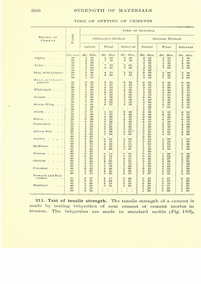
7/30/2019 Textbook on Streng 00 Slo Crich
http://slidepdf.com/reader/full/textbook-on-streng-00-slo-crich 344/433
300 STRENGTH OF MATERIALS
TIME OF SETTING OF CEMENTS
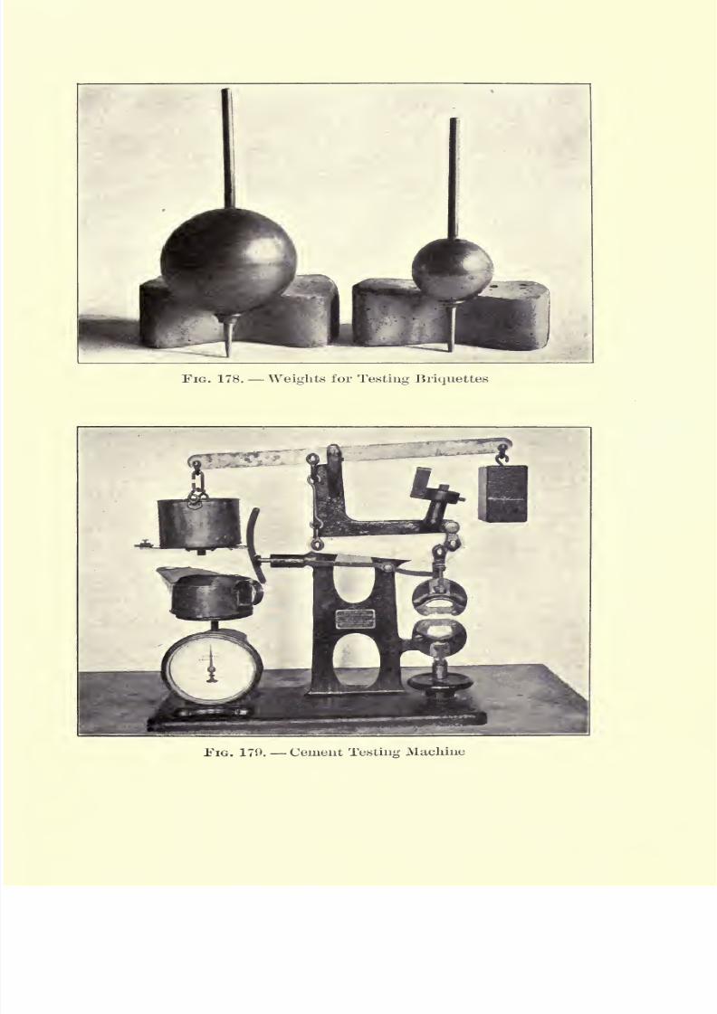
7/30/2019 Textbook on Streng 00 Slo Crich
http://slidepdf.com/reader/full/textbook-on-streng-00-slo-crich 345/433
FIG. 178. Weights for Testing Briquettes
EIG. 170. Cement Testing Machine

7/30/2019 Textbook on Streng 00 Slo Crich
http://slidepdf.com/reader/full/textbook-on-streng-00-slo-crich 346/433

7/30/2019 Textbook on Streng 00 Slo Crich
http://slidepdf.com/reader/full/textbook-on-streng-00-slo-crich 347/433
LIME, CEMENT, AND. CONCRETE 301
FIG. 180
which provide for a cross section of one square inch at the middle,
with thicker ends for insertion in the jaws of the testing machine.
This test requires considerable expertness to get satisfactory results,
for the proper mix-
ing and tamping into
the molds can only
be satisfactorily done
by one of consider-
able experience. After molding, the briquettes are kept under a damp
cloth for about twenty-four hours and then under water until tested.
Many machines are now made for testing the tensile strength of
cement, most of them being light enough to be portable. A new
automatic machine, manufactured by the Olsen Testing Machine
Company of Philadelphia, is shown in Fig. 179. The machine is
operated by first placing the briquette in position and balancing the
beam at the top. The load is then applied by allowing the shot to run
from the pan on the right end of the beam. The spring balance gives
the exact weight of the shot and, consequently, the tensile stress on the
briquette at any time during the test. After the briquette is broken
the tensile strength in pounds per square inch is recorded on the dial.
212. Speed of application of load. It has been found that the
rapidity with which the load is applied has considerable effect upon
the results obtained in making tension tests of cement. The follow-
ing table clearly shows this effect.*
EFFECT OF SPEED OF APPLICATION OF LOAD ON TENSILE
STRENGTH OF CEMENT
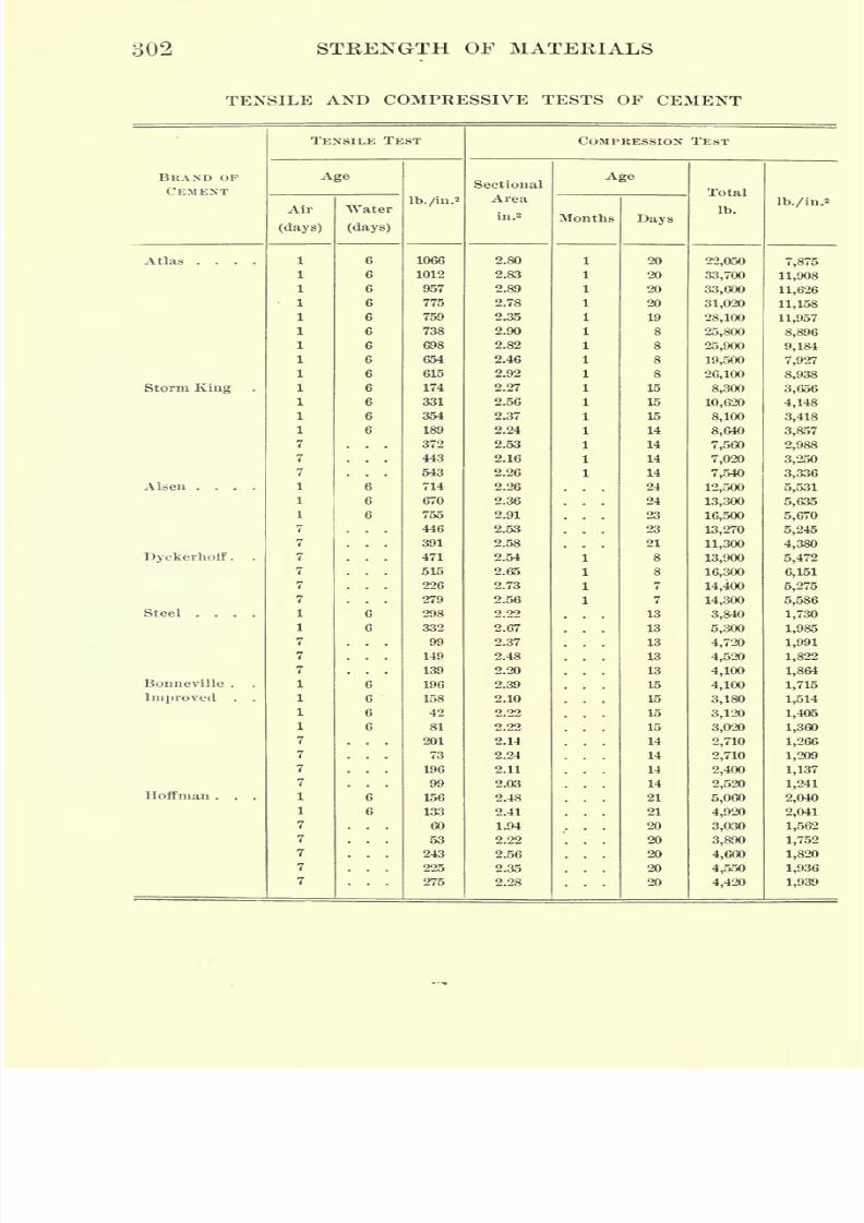
7/30/2019 Textbook on Streng 00 Slo Crich
http://slidepdf.com/reader/full/textbook-on-streng-00-slo-crich 348/433
302 STRENGTH OF MATERIALS
TENSILE AND COMPRESSIVE TESTS OF CEMENT
BRAND OF
CEMENT
7/30/2019 Textbook on Streng 00 Slo Crich
http://slidepdf.com/reader/full/textbook-on-streng-00-slo-crich 349/433
LIME, CEMENT, AND CONCRETE 303
213. Compression tests. Compression tests of cement are made
in Europe, but not generally by engineers in the United States, as
the tensile test is thought quite as valuable as the compression test
in giving results indicative of the strength of the cement. Compres-
sion tests are made upon the ends of the specimen broken in tension,
or upon specially prepared cement cubes. The use of the broken
ends of the briquette insures the same material for the compression
test as was used in the tension test. The table on page 302 gives the
compressive strength of several brands of cement.* The tests were
made by compressing halves of briquettes broken in tension., and
both the tensile and compressive strengths are given.
214. Standard specifications for cement. The following is a copy
of the standard specifications for cement adopted by the American
Society for Testing Materials.
NATURAL CEMENT
This term shall be applied to the finely pulverized product resulting from
the calcination of an argillaceous limestone at a temperature only sufficient
to drive off the carbonic acid gas.
Fineness. It shall leave by weight a residue of not more than 10 per cent
on the No. 100 sieve, and not more than 30 per cent on the No. 200 sieve.
Time of setting. It shall develop initial set in not less than ten minutes,
and hard set in not less than thirty minutes nor more than three hours.
Tensile strength. The minimum requirements for tensile strength forjbri-
quettes 1 in. square in cross section shall be as follows, and shall show no
retrogression in strength within the periods specified.
Neat Cement
AGE STRENGTH
24 hours in moist air 75 Ib.
7 days (1 day in moist air, 6 days in water) 150 "
28 days (1 27 ")
250
One Part Cement, Three Parts Standard Sand
7 days (1 day in moist air, 6 days in water) ..... 50 Ib.
28 days (1 27)
125
* Watertown Arsenal Report, 1901.
7/30/2019 Textbook on Streng 00 Slo Crich
http://slidepdf.com/reader/full/textbook-on-streng-00-slo-crich 350/433
304 STRENGTH OF MATERIALS
Constancy of volume. Pats of neat cement about 3 in. in diameter, | in.
thick at the center, tapering to a thin edge, shall be kept in moist air for a
period of twenty-four hours.
(a)
A pat is then kept in air at normal temperature.
(ft)Another is kept in water maintained as near 70 F. as practicable.
These pats are observed at intervals for at least twenty-eight days, and, to
satisfactorily pass the tests, should remain firm and hard and show no signs
of distortion, checking, cracking, or disintegrating.
PORTLAND CEMENT .
This term is applied to the finely pulverized product resulting from the
calcination to incipient fusion of an intimate mixture of properly proportioned
argillaceous and calcareous materials, and to which no addition greater than
3 per cent has been made subsequent to calcination.
Specific gravity. The specific gravity of the cement, thoroughly dried at
100 C., shall be not less than 3.10.
Fineness. It shall leave by weight a residue of not more than 8 per cent on
the No. 100 sieve, and not more than 25 per cent on the No. 200 sieve.
Timeof
setting.It shall
developinitial set in not less
than thirty minutes,and hard set in not less than one hour nor more than ten hours.
Tensile strength. The minimum requirements for tensile strength for bri-
quettes 1 in. square in section shall be as follows, and shall show no retro-
gression in strength within the periods specified.
Neat Cement
AGE STRENGTH*24 hours in moist air 175 Ih.
7 days (1 day in moist air, 6 days in water) 500 "
28 days (1 27 ")
600 "
One Part Cement, Three Parts Standard Sand
7 days (1 day in moist air, 6 days in water) 200 Ib.
28 days (1" " 27 " "
)275
Constancy of volume. Pats of neat cement about 3 in. in diameter, ^in.
thick at the center, and tapering to a thin edge, shall be kept in moist air
for a period of twenty-four hours.
(a) A pat is then kept in air at normal temperature and observed at intervals
for at least twenty-eight days.
(5) Another pat is kept in water maintained as near 70 F. as practicable,
and observed at intervals for at least twenty-eight days.
7/30/2019 Textbook on Streng 00 Slo Crich
http://slidepdf.com/reader/full/textbook-on-streng-00-slo-crich 351/433
LIME, CEMENT, AND CONCRETE 305
(c)A third pat is exposed in any convenient way in an atmosphere of
steam, above boiling water, in a loosely closed vessel for five hours.
These pats, to satisfactorily pass the requirements, shall remain firm and
hard and show no signs of distortion, checking, cracking, or
disintegrating.Sulphuric acid and magnesia. The cement shall not contain more than 1.75
per cent of anhydrous sulphuric acid (SO 3),nor more than 4 per cent of
magnesia (MgO).
215. Concrete. When cement mortar is mixed with certain per-
centages of broken stone, gravel, or cinders, the mixture is called
concrete. The amount and kind of stone or other material to be used
depends upon the use to be made of the finished product. Concrete
is rapidly coming into favor as a building material, and is replacing
brick and stone in many classes of structures. If properly made it is
a much better building material than either of the latter, and has an
additional advantage in the fact that it can be handled by unskilled
labor and may be readily molded into any desired form. In view of
these facts, a study of its properties is of the greatest importance.
216. Mixing of concrete. In making concrete, the sand and cement
are first thoroughly mixed and gauged with the right amount of water.
The stone, having previously been moistened, is then added, and the
whole is thoroughly mixed until each piece of stone is coated with the
cement mortar. These two operations are often combined into one.
The amount of water to be used in making the mortar depends upon
the character of the concrete desired. A medium concrete may be
obtained by adding enough water so that moisture comes to the
surface when the mortar is struck with a shovel.
After mixing, the concrete is tamped, or rammed, into position.
This tamping should be thoroughly done, since in no other way can
as dense a mixture be obtained. It is desirable that all the voids
(spaces between the broken stone) should be filled as compactly as
possible with mortar.
217. Tests of concrete. Concrete is usually tested in compression,
and for this purpose 6-inch cubes *are made, composed of cement,
sand, and broken stone in the proportions of 1 : 2 : 4 or 1 : 3 : 6. In
some cases the proportion to be used in the particular work con-
cerned is also used in making the test cubes. These cubes are made
in molds and allowed to set in air, or part of the time in air and the
*Cylinders or larger cubes are also sometimes used.
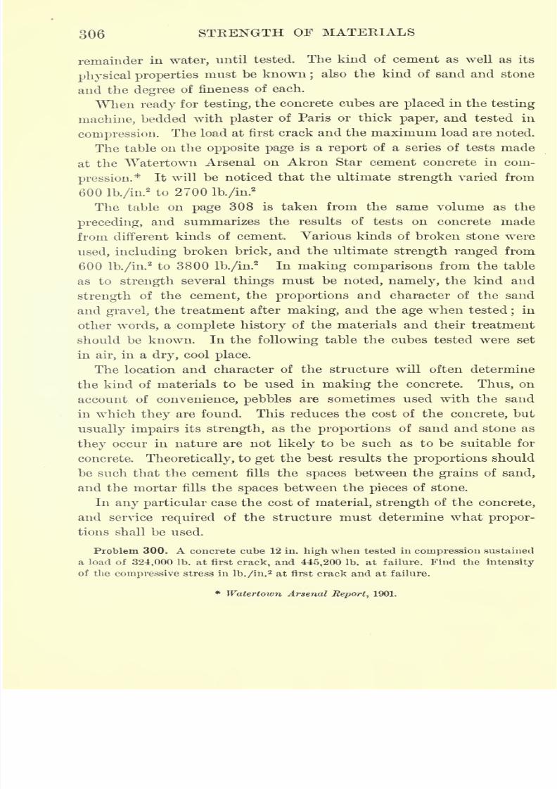
7/30/2019 Textbook on Streng 00 Slo Crich
http://slidepdf.com/reader/full/textbook-on-streng-00-slo-crich 352/433
306 STRENGTH OF MATERIALS
remainder in water, until tested. The kind of cement as well as its
physical propertiesmust be known
;also the kind of sand and stone
and the degree of fineness of each.
When ready for testing, the concrete cubes are placed in the testing
machine, bedded with plaster of Paris or thick paper, and tested in
compression. The load at first crack and the maximum load are noted.
The table on the opposite page is a report of a series of tests made
at the "Watertown Arsenal on Akron Star cement concrete in com-
pression.* It will be noticed that the ultimate strength varied from
600 lb./in.2to 2700 lb./in.
2
The table on page 308 is taken from the same volume as the
preceding, and summarizes the results of tests on concrete made
from different kinds of cement. Various kinds of broken stone were
used, including broken brick, and the ultimate strength ranged from
600 lb./iu.2to 3800 lb./in.
2In making comparisons from the table
as to strength several things must be noted, namely, the kind and
strength of the cement, the proportions and character of the sand
and gravel, the treatment after making, and the age when tested;in
other words, a complete history of the materials and their treatment
should be known. In the following table the cubes tested were set
in air, in a dry, cool place.
The location and character of the structure will often determine
the kind of materials to be used in making the concrete. Thus, on
account of convenience, pebbles are sometimes used with the sand
in which they are found. This reduces the cost of the concrete, but
usually impairs its strength, as the proportions of sand and stone as
they occur in nature are not likely to be such as to be suitable for
concrete. Theoretically, to get the best results the proportions should
be such that the cement fills the spaces between the grains of sand,
and the mortar fills the spaces between the pieces of stone.
In any particular case the cost of material, strength of the concrete,
and service required of the structure must determine what propor-
tions shall be used.
Problem 300. A concrete cube 12 in. high when tested in compression sustained
a load of 324,000 Ib. at first crack, and 445,200 Ib. at failure. Find the intensity
of the compressive stress in lb./in.2 at first crack and at failure.
* Watertown Arsenal Report, 1901.
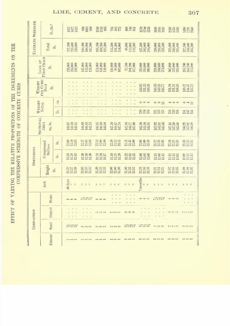
7/30/2019 Textbook on Streng 00 Slo Crich
http://slidepdf.com/reader/full/textbook-on-streng-00-slo-crich 353/433
LIME, CEMENT, AND CONCRETE 307
pc>?3 rH
l~ C5 O CO O C-l Iffl C3 CI O rH * C, 71 O t-- C-1 O 00 M Cl C-l W ^H l~ tt 1<,-i,-ir-i -t>55Tt 55oco -HO^H QC^-IC-I c-to-t1 cicv i- co-foo IH So S(M C) <M r-<T-<T-> T-(r4r-( rH ,H rH ^H rH Cl CO CO 5> 5) CM C<5 CC C) C) rH CO
-"
E.
OOC-I *rti'
I-
i c-i <N c-i d c-i ci c-i c-i <N ci c<i d oi d d c-i d d d d d d d ci d d
.
ci d d d c-i i-5 c-i d d d d d d d d d c-i d d c-i c-i c-i d ci
^3 822?i22
88S2
28^
c-i ci d d d d d d d d d i-3 rH d d d d d c-i
CO CO CO I- L- t- 00 00 CO
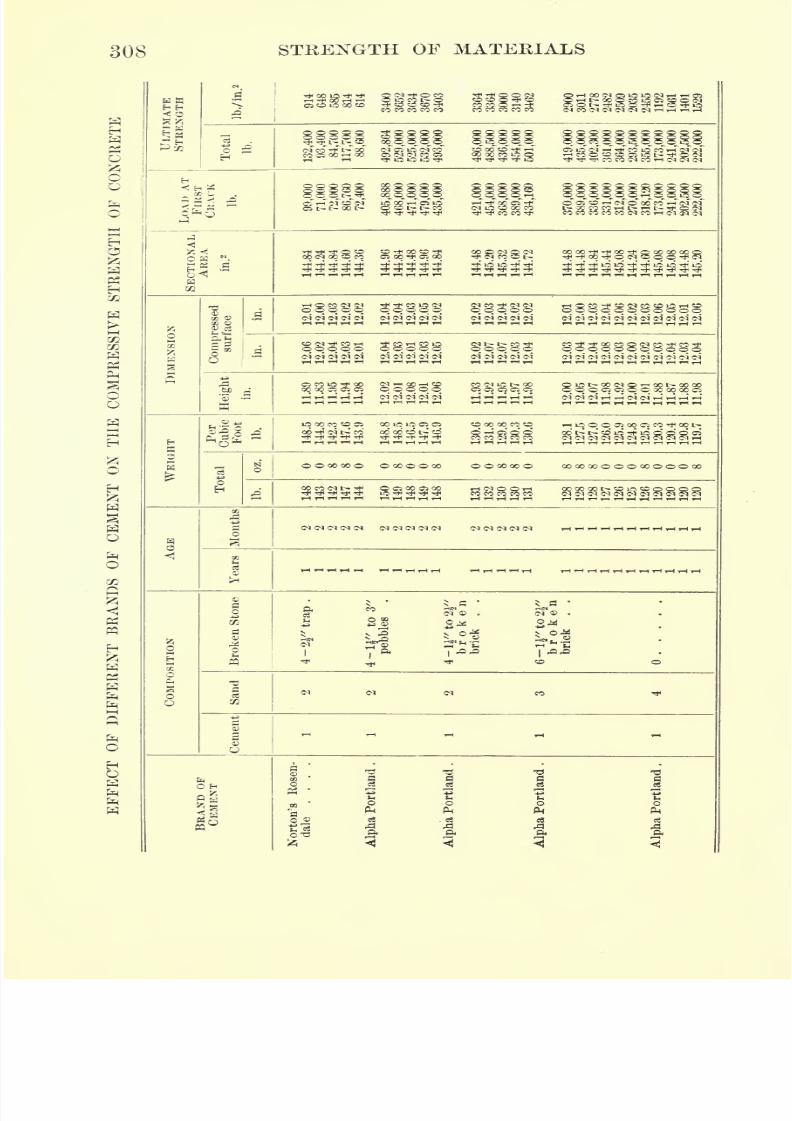
7/30/2019 Textbook on Streng 00 Slo Crich
http://slidepdf.com/reader/full/textbook-on-streng-00-slo-crich 354/433
308 STRENGTH OF MATERIALS
CNrHTHCi^O
Q0
s .a
w
ooooocco r-iooocioooscc^t*oot>
O O 00 00 O O 00 O O 00 O O 00 00 O 00 00 00 O O O 00 O OO
00 00 <M t~ * Orf^rt'Tft'* iO-
<N <N (M <N (M IM (M
SH
2
tfW
g^O
II
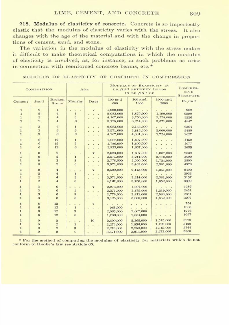
7/30/2019 Textbook on Streng 00 Slo Crich
http://slidepdf.com/reader/full/textbook-on-streng-00-slo-crich 355/433
LIME, CEMENT, AND CONCRETE 309
218. Modulus of elasticity of concrete. Concrete is soimperfectly
elastic that the modulus of elasticity varies with the stress. It also
changes with the age of the material and with the change in propor-
tions of cement, sand, and stone.
The variation in the modulus of elasticity with the stress makes
it difficult to make theoretical computations in which the modulus
of elasticity is involved, as, for instance, in such problems as arise
in connection with reenforced concrete beams, etc.*
MODULUS OF ELASTICITY OF CONCRETE IN COMPRESSION
COMPOSITION
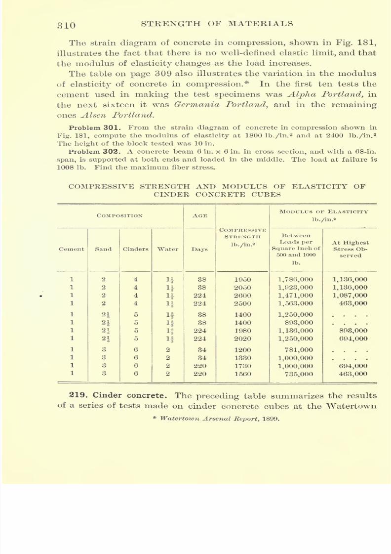
7/30/2019 Textbook on Streng 00 Slo Crich
http://slidepdf.com/reader/full/textbook-on-streng-00-slo-crich 356/433
310 STRENGTH OF MATERIALS
The strain diagram of concrete in compression, shown in Fig. 181,
illustrates the fact that there is no well-defined elastic limit, and that
the modulus of elasticity changes as the load increases.
The table on page 309 also illustrates the variation in the modulus
of elasticity of concrete in compression.* In the first ten tests the
cement used in making the test specimens was Alpha Portland, in
the next sixteen it was Germania Portland, and in the remaining
ones Alsen Portland.
Problem 301. From the strain diagram of concrete in compression shown in
Fig. 181, compute the modulus of elasticity at 1800 lb./in.2 and at 2400 lb./in.
2
The height of the block tested was 10 in.
Problem 302. A concrete beam 6 in. x 6 in. in cross section, and with a 68-in.
span, is supported at both ends and loaded in the middle. The load at failure is
1008 Ib. Find the maximum fiber stress.
COMPRESSIVE STRENGTH AND MODULUS OF ELASTICITY OF
CINDER CONCRETE CUBES
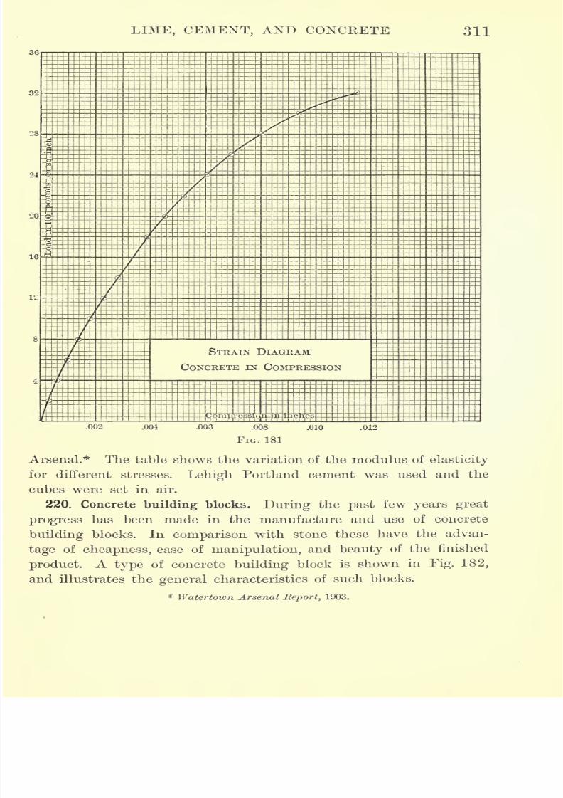
7/30/2019 Textbook on Streng 00 Slo Crich
http://slidepdf.com/reader/full/textbook-on-streng-00-slo-crich 357/433
LIME, CEMENT, AND CONCRETE 311
32
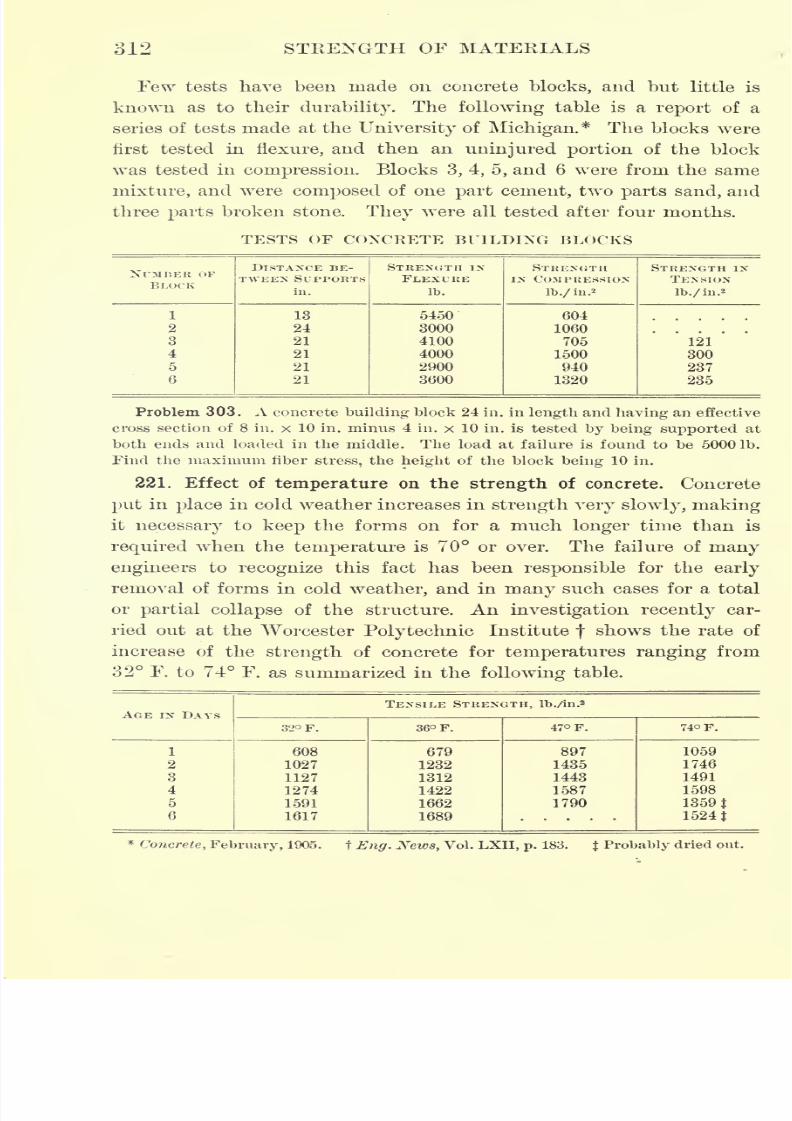
7/30/2019 Textbook on Streng 00 Slo Crich
http://slidepdf.com/reader/full/textbook-on-streng-00-slo-crich 358/433
312 STRENGTH OF MATERIALS
Few tests have been made on concrete blocks, and but little is
known as to their durability. The following table is a report of a
series of tests made at the University of Michigan.* The blocks were
first tested in flexure, and then an uninjured portion of the block
was tested in compression. Blocks 3, 4, 5, and 6 were from the same
mixture, and were composed of one part cement, two parts sand, and
three parts broken stone. They were all tested after four months.
TESTS OF CONCRETE BUILDING BLOCKS
NTMKEK OF
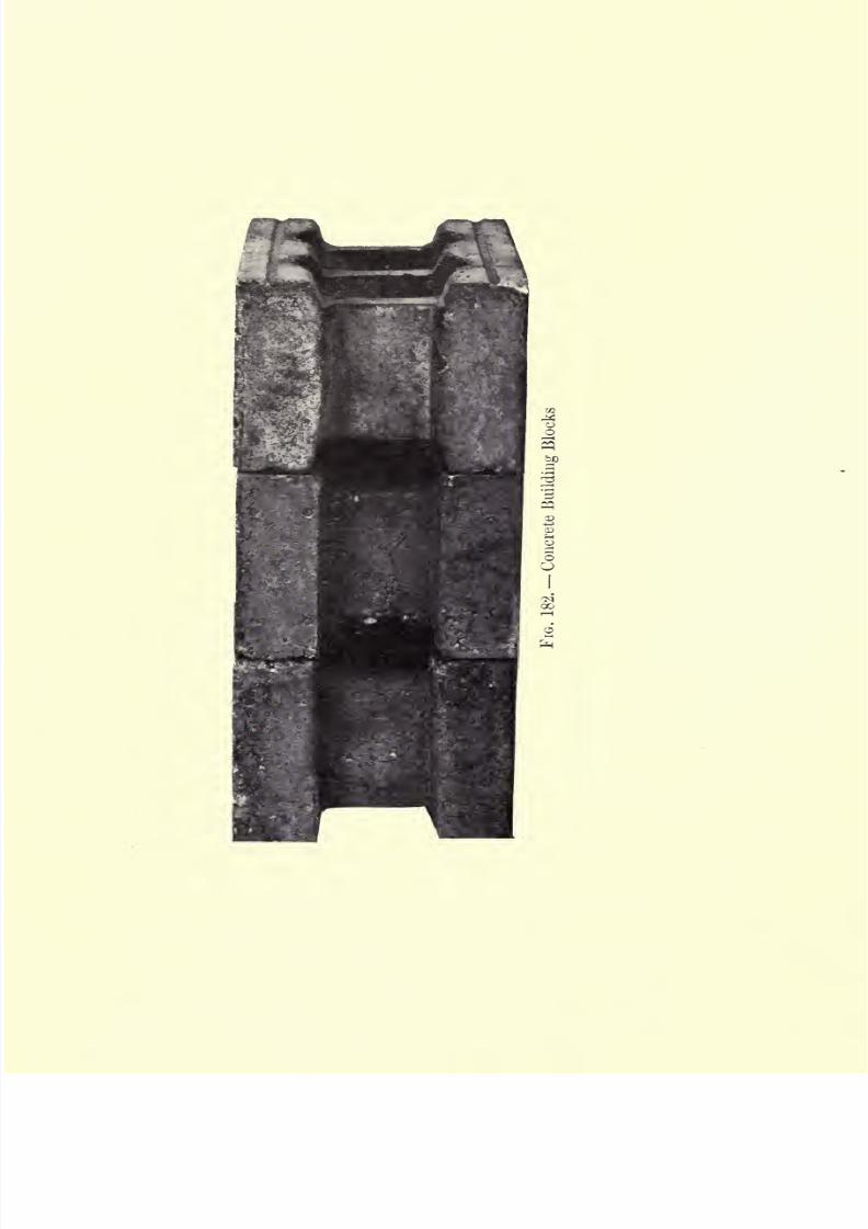
7/30/2019 Textbook on Streng 00 Slo Crich
http://slidepdf.com/reader/full/textbook-on-streng-00-slo-crich 359/433
7/30/2019 Textbook on Streng 00 Slo Crich
http://slidepdf.com/reader/full/textbook-on-streng-00-slo-crich 360/433
7/30/2019 Textbook on Streng 00 Slo Crich
http://slidepdf.com/reader/full/textbook-on-streng-00-slo-crich 361/433
CHAPTER XIY
REENFORCED CONCRETE
222. Object of reenforcement. The fact that concrete is much
stronger in compression than in tension has led to attempts to
increase its tensile
strength by imbeddingsteel .or iron rods in the
material. This metal reinforcement is so designed as to carry most of
the tensile stress, and thus plays the same part in a concrete structure
as the tension members play in a truss.
It has been found by experiment that reenforced concrete beams
may be stressed in flexure far beyond the elastic limit* of ordinary
concrete, and even beyond the stress which would rupture the same
beam,if not
reenforced,without
appreciable injuryto the material.
M. Considere, one of the leading French authorities on the subject,
reports a test of this kind, in which he found that concrete taken
from the tensile side of a reenforced concrete beam tested in flexure
was uninjured by the strain. Professor Turneaure, of the University
of Wisconsin, has found that minute cracks occur on the tension side
of 'a reenforced concrete beam as soon as the fiber stress reaches the
pointat
which non-reenforced concrete would crack, f Experimentsof this kind seem to indicate that the metal reenforcement carries
practically all of the tensile stress, as cracks in the concrete must
certainly reduce its tensile strength to zero at this point.
223. Corrosion of the metal reenforcement. The maintenance of
the increased strength of concrete due to the metal reenforcement
depends upon the preservation of the metal. The corrosion of metal
imbedded in concrete is thus a matter of the greatest importancein
connection with reenforced concrete work. It has been found that
metal thus protected does not corrode even though the concrete be
* As indicated in Chapter XIII, concrete shows no well-defined elastic limit, i.e. the
material does not conform to Hooke's law. In this case elastic limit means the arbitrary
point beyond which the deformations are much more noticeable than formerly.
t Proc. Amer. Soc.for Testing Materials, 1905.
313
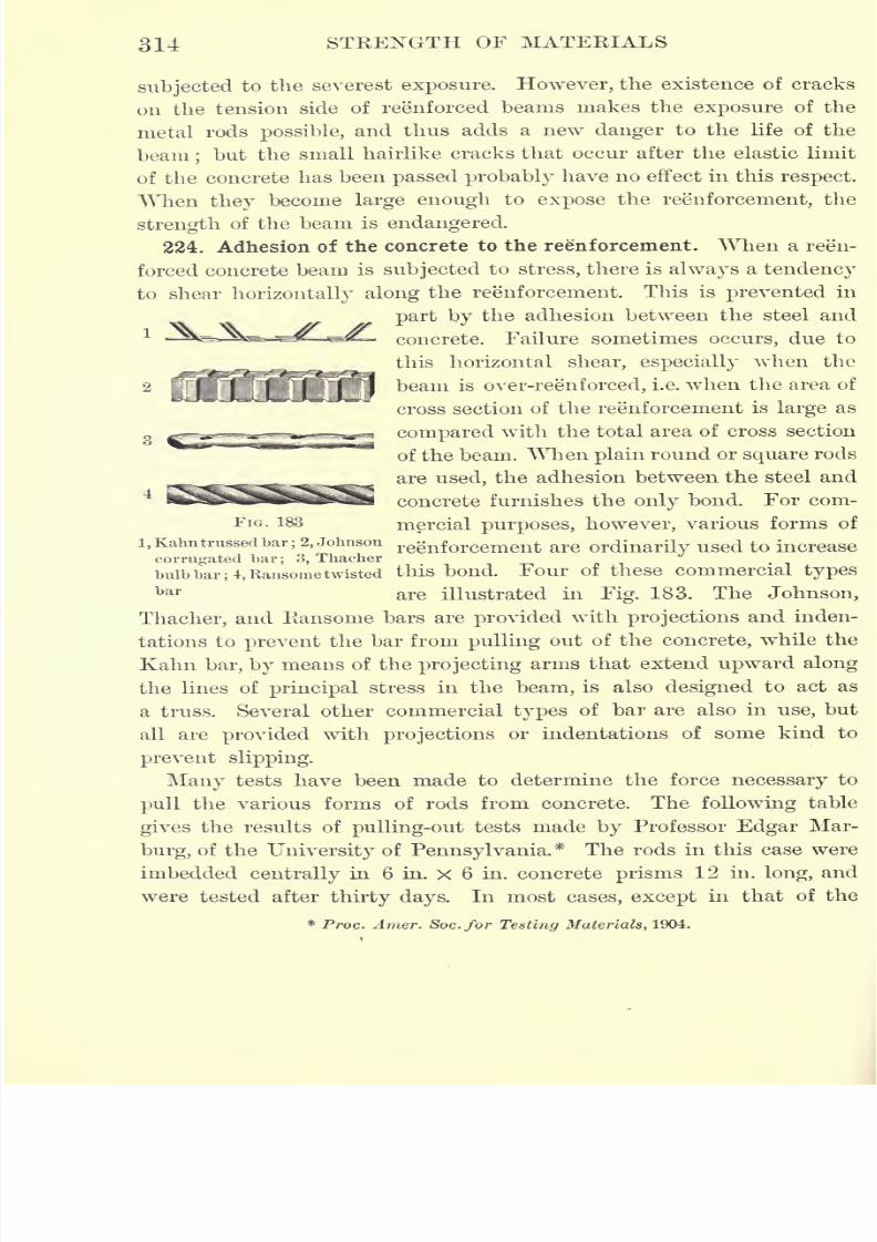
7/30/2019 Textbook on Streng 00 Slo Crich
http://slidepdf.com/reader/full/textbook-on-streng-00-slo-crich 362/433
314 STRENGTH OF MATERIALS
subjected to the severest exposure. However, the existence of cracks
on the tension side of reenforced beams makes the exposure of the
metal rods possible, and thus adds a new danger to the life of the
beam;
but thesmall hairlike cracks that occur after the elastic limit
of the concrete has been passed probably have no effect in this respect.
When they become large enough to expose the reenforcement, the
strength of the beam is endangered.
224. Adhesion of the concrete to the reenforcement. When a reen-
forced concrete beam is subjected to stress, there is always a tendency
to shear horizontally along the reenforcement. This is prevented in
part bythe adhesion between the steel and
1-=Sfctz-.^gL. Tzy ii_j^ concrete. Failure sometimes occurs, due to
this horizontal shear, especially when the
beam is over-reenforced, i.e. when the area of
cross section of the reenforcement is large as
compared with the total area of cross section
of the beam. When plain round or square rods
areused,
the adhesion between the steel and
concrete furnishes the only bond. For com-
FIG. 183 mercial purposes, however, various forms of
i,Kahn trussed bar; 2, Johnson regnforcement are ordinarily used to increasecorrugated bar
; 3, Thaeher
bulb bar; 4, Ransome twisted tliis bond. Four of these commercial types
bar are illustrated in Fig. 183. The Johnson,
Thaeher, and Ransome bars are provided with projections and inden-
tations to prevent thebar
from pullingout of the
concrete,while the
Kahn bar, by means of the projecting arms that extend upward along
the lines of principal stress in the beam, is also designed to act as
a truss. Several other commercial types of bar are also in use, but
all are provided with projections or indentations of some kind to
prevent slipping.
Many tests have been made to determine the force necessary to
pull the various forms of rods from concrete. The followingtable
gives the results of pulling-out tests made by Professor Edgar Mar-
burg, of the University of Pennsylvania.* The rods in this case were
imbedded centrally in 6 in. X 6 in. concrete prisms 12 in. long, and
were tested after thirty days. In most cases, except in that of the
* Proc. Amer. Soc.for Testing Materials, 1904.
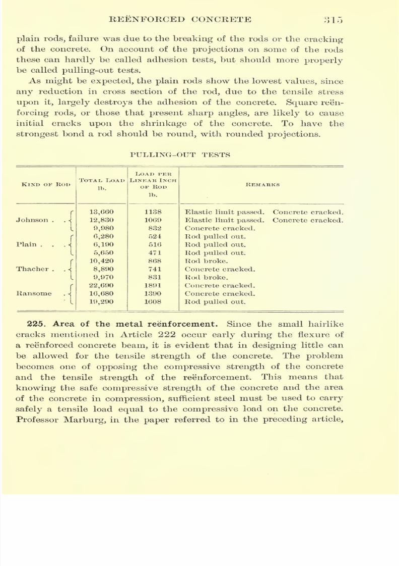
7/30/2019 Textbook on Streng 00 Slo Crich
http://slidepdf.com/reader/full/textbook-on-streng-00-slo-crich 363/433
REENFORCED CONCRETE 315
plain rods, failure was due to the breaking of the rods or the cracking
of the concrete. On account of the projections on some of the rods
these can hardly be called adhesion tests, but should more properly
be calledpulling-out
tests.
As might be expected, the plain rods show the lowest values, since
any reduction in cross section of the rod, due to the tensile stress
upon it, largely destroys the adhesion of the concrete. Square reen-
forcing rods, or those that present sharp angles, are likely to cause
initial cracks upon the shrinkage of the concrete. To have the
strongest bond a rod should be round, with rounded projections.
PULLING-OUT TESTS
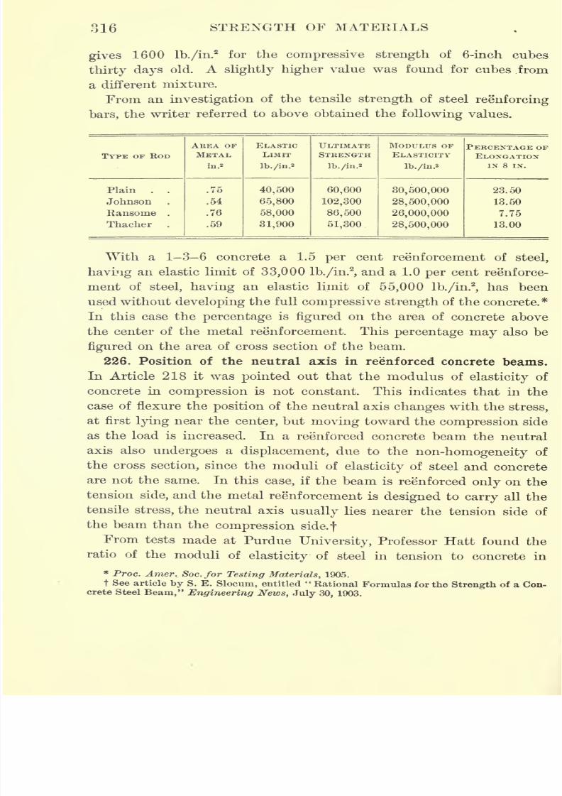
7/30/2019 Textbook on Streng 00 Slo Crich
http://slidepdf.com/reader/full/textbook-on-streng-00-slo-crich 364/433
316 STEENGTH OF MATERIALS
gives 1600 lb./in.2
for the compressive strength of 6-inch cubes
thirty days old. A slightly higher value was found for cubes from
a different mixture.
From an investigationof the tensile
strengthof steel
reenforcing
bars, the writer referred to above obtained the following values.
7/30/2019 Textbook on Streng 00 Slo Crich
http://slidepdf.com/reader/full/textbook-on-streng-00-slo-crich 365/433
KEENFORCED CONCRETE 317
compression, for certain grades of material to be as follows.* The use
of this ratio is exemplified in the following article.
Stone concrete 23 days 8.8
Stone concrete 00 days 6.6
Average 7.7
Gravel concrete 28 days 8.0
Gravel concrete 90 days 6.2
Average 7.1
227. Strength of reenforced concrete beams. Concrete is weak in
tension and strong in compression, so that when used in the form of
a beam, the tensile strength controls the strength of the beam. To
correct for this lack of strength in tension, steel rods are imbedded in
beams in such a way as to carry the tensile stresses.
A few years ago engineers believed that the tensile strength of the
concrete in a beam might be considered in computing the strength of
the reenforced concrete beam. At present, however, the steel reen-
forcement is designed to carry all the load in tension and the con-
crete all the load in compression ;that is, the tensile strength of the
steel is balanced against the compressive strength of the concrete.
Since concrete is imperfectly elastic, the stress-strain diagram is not
quite a straight line in any part of its length. This means that its
modulus of elasticity is not constant, but changes with the stress.
The results of many tests show that the stress-strain diagram for
concrete may be assumed a parabola, so that the compressive stress
on any section of the beam varies as the ordinates of a parabola.
On account of the difference in the modulus of elasticity of steel
and concrete (30,000,000 lb./in.2and 2,000,000 lb./in.
2to 2,500,000
lb./in.2
),the position of the neutral axis changes with the load on the
beam. In the following analysis the assumptions of the common
theory of flexure are supposed to hold, with the exception of the
points stated above.
Let I = length of span,
x distance of the neutral axis from the compression face,
d = effective depth of beam;that is, the distance from top of
beam to center of gravity of reenforcement,
* Jour. Western Soc. Eng., June, 1904.

7/30/2019 Textbook on Streng 00 Slo Crich
http://slidepdf.com/reader/full/textbook-on-streng-00-slo-crich 366/433
318 STRENGTH OF MATERIALS
r = ratio of area of steel to that of the effective cross section
of the beam,
Es= modulus of elasticity of steel,
Ec= modulus of elasticity of concrete in compression,
ps= unit stress in metal reinforcement,
pc= unit compression stress in the concrete at outer fiber,
e = unit contraction in concrete, and er
unit elongation in the
steel,
Ecis measured at stress pc
.
The beam is supposed reenforced on the tension side only, and the
rods are imbedded to a sufficient depth to protect the steel. (This
p
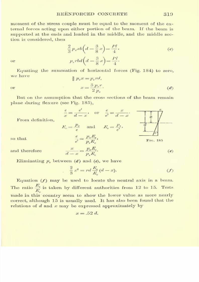
7/30/2019 Textbook on Streng 00 Slo Crich
http://slidepdf.com/reader/full/textbook-on-streng-00-slo-crich 367/433
REENFORCED CONCRETE 319
moment of the stress couple must be equal to the moment of the ex-
ternal forces acting upon either portion of the beam. If the beam is
supported
at the ends and loaded in the middle, and the middle sec-
tion is considered, then
2 ,/, 3 \ PI
-g*)=->
orPI~
Equating the summation of horizontal forces (Fig. 184) to zero,
we have
or
But on the assumption that the cross sections of the beam remain
plane during flexure (see Fig. 185),
e e' eor :
From definition,
so that
and therefore
x d x
E. = -& and
Eliminating pebetween (d) and
(e),we have
O 77Y
x2 = rd
'
(d x). (/)3 E
c
Equation (/) may be used to locate the neutral axis in a beam.
The ratio - is taken by different authorities from 12 to 15. Tests
made in this country seem to show the lower value as more nearly
correct, although 15 is usually used. It has also been found that the
relations of d and x may be expressed approximately by
x = .52 d.
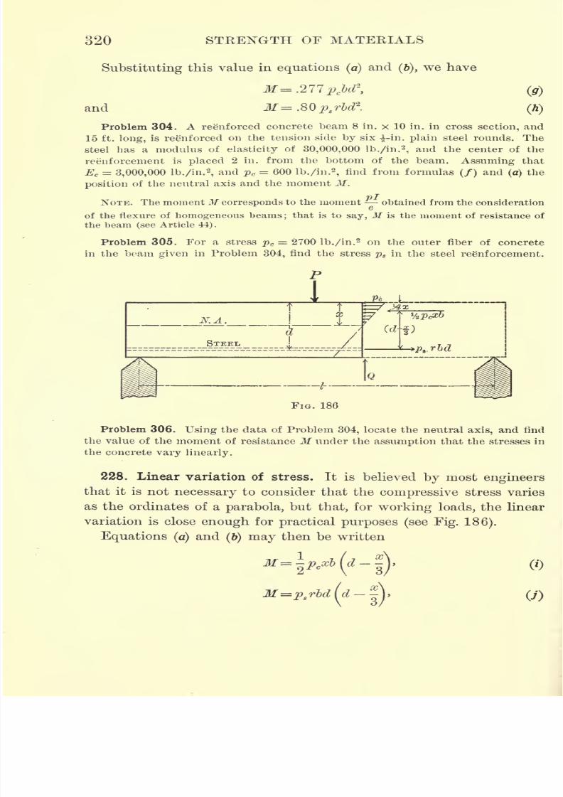
7/30/2019 Textbook on Streng 00 Slo Crich
http://slidepdf.com/reader/full/textbook-on-streng-00-slo-crich 368/433
320 STRENGTH OF MATERIALS
Substituting this value in equations (a)and
(6),we have
and M= .80p8rbd?.
(h)
Problem 304. A reenforced concrete beam 8 in. x 10 in. in cross section, and
15 ft. long, is reenforced on the tension side by six --in. plain steel rounds. The
steel has a modulus of elasticity of 30,000,000 lb./in.2
,and the center of the
reenforcement is placed 2 in. from the bottom of the beam. Assuming that
Ec = 3,000,000 lb./in.2
,and pc = 600 lb./in.
2,find from formulas (/) and
(a) the
position of the neutral axis and the moment M.
NOTE. The momentM corresponds to the moment obtained from the consideration
of the flexure of homogeneous beams; that is to say, M is the moment of resistance of
the beam (see Article 44).
Problem 305. For a stress pc = 2700 lb./in.2 on the outer fiber of concrete
in the beam given in Problem 304, find the stress ps in the steel reenforcement.
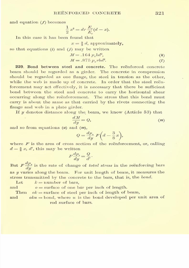
7/30/2019 Textbook on Streng 00 Slo Crich
http://slidepdf.com/reader/full/textbook-on-streng-00-slo-crich 369/433
BEENFORCED CONCEETE 321
and equation (/) becomes
-a* =drjj(d-x).
In this case it has been found that
x=^ d, approximately,
so that equations (/)and
(j) may be written
\ (ft)
229. Bond between steel and concrete. The reenforced concrete
beam should be regarded as a girder. The concrete in compression
should be regarded as one flange, the steel in tension as the other,
while the web is made up of concrete. In order that the steel reen-
forcement may act effectively, it is necessary that there be sufficient
bond between the steel and concrete to carry the horizontal shear
occurring along the reenforcernent. The stress that this bond must
carry is about the same as that carried by the rivets connecting the
flange and web in a plate girder.
If y denotes distance along the beam, we know (Article 53) that
?=and so from equations (a)
and(m),
g_&W,_|y \
8
where F is the area of cross section of the reenforcement, or, calling
d| x, d', this may be written
Fdps = Q
dy d'
But F is the rate of change of total stress in the reenforcing bars
dyas
y
varies
along
the beam. For unit
length
of beam, it measures the
stress transmitted by the concrete to the bars, that is, the bond.
Let k = number of bars,
and o = surface of one bar per inch of length.
Then ok = surface of steel per inch of length of beam,
and oku = bond, where u is the bond developed per unit area of
rod surface of bars.
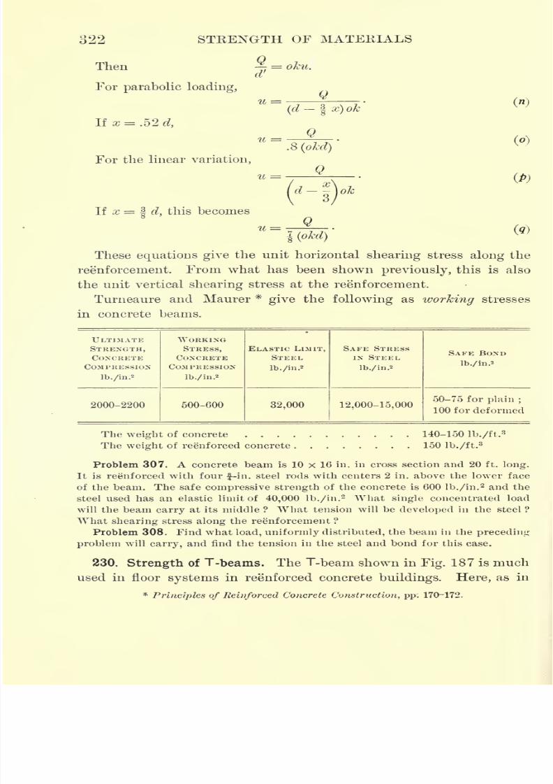
7/30/2019 Textbook on Streng 00 Slo Crich
http://slidepdf.com/reader/full/textbook-on-streng-00-slo-crich 370/433
322
Then
For parabolic loading,
If x = .52 d,
STEENGTH OF MATEEIALS
- == oku.
_Q(d | x) ok
u =
For the linear variation,
If x = | d, this becomes
.8 (okd)
_Q
Q
(A
l(okd)
These equations give the unit horizontal shearing stress along the
reenforcement. From what has been shown previously, this is also
the unit vertical shearing stress at the reenforcement.
Turneaure and Maurer *give the following as working stresses
in concrete beams.
ULTIMATE
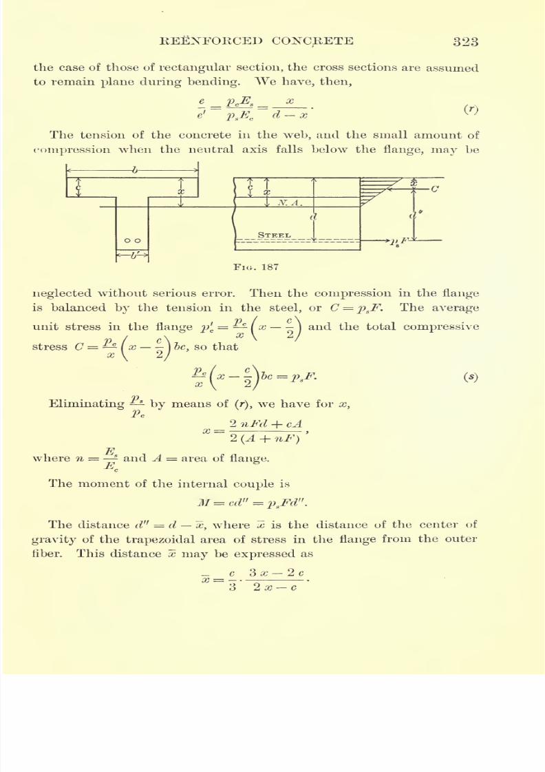
7/30/2019 Textbook on Streng 00 Slo Crich
http://slidepdf.com/reader/full/textbook-on-streng-00-slo-crich 371/433
REENFORCED CONCRETE 323
the case of those of rectangular section, the cross sections are assumed
to remain plane during bending. We have, then,
e' psE
cd-x
The tension of the concrete in the web, and the small amount of
compression when the neutral axis falls below the flange, may be
7/30/2019 Textbook on Streng 00 Slo Crich
http://slidepdf.com/reader/full/textbook-on-streng-00-slo-crich 372/433
324 STRENGTH OF MATERIALS
The resisting moment of the T-beam may now be written
x) ) (t)
or M=2isF(d-x). (u)
If the neutral axis falls within the flange, then d", the arm of the
internal couple, will be greater than d , so that a safe approximationo
for the resisting moment is obtained by using
or
When the neutral axis falls on the lower edge of the flange, these
formulas (v) and (w) are exactly true.
The horizontal shear in the case of T-bearns may be obtained as
follows. From equation (u)
_~
==^ Irtd _x) == Qdy dy
Qand -T-^ = OKU,
d x
where oku has the same meaning as in the case of rectangular
beams. So that
Qu =
or, from(w),
ok (d x)
Q_
~3
231. Shear at the neutral axis. If the tension in the concrete
is neglected, in the case of rectangular beams, the horizontal shear
at the neutral axis must be equal to the horizontal shear along the
reenforcement. If u r
is the unit horizontal shearing stress in the
7/30/2019 Textbook on Streng 00 Slo Crich
http://slidepdf.com/reader/full/textbook-on-streng-00-slo-crich 373/433
REENFORCED CONCRETE 325
concrete at the neutral axis and b is the width of the beam, then
bu' = shear per unit length of beam, at the neutral axis, and so
"'=!
and therefore for parabolic variation of stress
Q
and for linear variation of stress
o
In the case of the T-beams, if the tension in the web is neglected,
the horizontal shear where the web joins the flange must be equal to
the shear along the steel. Then
and so
b'(d-
x)
7/30/2019 Textbook on Streng 00 Slo Crich
http://slidepdf.com/reader/full/textbook-on-streng-00-slo-crich 374/433
CHAPTER XV
BRICK AND BUILDING STONE
232. Limestone. Limestone is principally a carbonate of lime, made
upof seashells that have been deposited from water
during past
geological times. Its method of formation has much to do with its
value as a building material. If it contains no thin layers of clay
or shale (sedimentary planes), it is likely to be fairly homogeneous in
structure. But if layers of shale, however small, occur, the material
is much more quickly weathered. This is especially true if the stone
be placed at right angles to the position it occupied in the quarry.
Thinplanes
of
foreign
substances arelikely
to occur in
manyof our best building stones, as may be seen in the rapid deteriora-
tion of seemingly first-class limestone when used as curbing. Such
disintegration is caused by a lessening of the adhesion between the
particles of stone.
Limestone may be composed of a great percentage of sand cemented
together by calcareous matter, in which case it is called siliceous lime-
stone. Under such circumstances chemical action
mayremove the
cementing material, thus leaving the stone free to crumble. Marble
is almost pure limestone.
Conditions to which a building stone is to be exposed will determine
the character of the material to be used in any particular structure.
Rapid freezing and thawing is likely to set up internal strains in the
material, which may lead to future failure. These strains may be
causedby unequal expansion
or contraction ofthe particles
of the
stone, or by the freezing and thawing of the water in the stone. The
formation of ice in the sedimentary planes accounts in a large measure
for the rapid deterioration of stone.
Limestone often occurs in very thick layers, as in the case of the
oolitic limestone found at Bedford, Indiana, where the layers are
often from 25 to 30 ft. thick. In such cases it is a most valuable
326
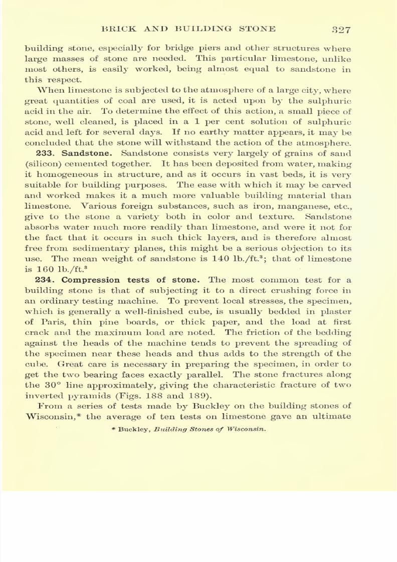
7/30/2019 Textbook on Streng 00 Slo Crich
http://slidepdf.com/reader/full/textbook-on-streng-00-slo-crich 375/433
BRICK AND BUILDING STONE 327
building stone, especially for bridge piers and other structures where
large masses of stone are needed. This particular limestone, unlike
mostothers,
is
easily worked, beingalmost
equalto sandstone in
this respect.
When limestone is subjected to the atmosphere of a large city, where
great quantities of coal are used, it is acted upon by the sulphuric
acid in the air. To determine the effect of this action, a small piece of
stone, well cleaned, is placed in a 1 per cent solution of sulphuric
acid and left for several days. If no earthy matter appears, it may be
concluded that the stone will withstand the action of theatmosphere.
233. Sandstone. Sandstone consists very largely of grains of sand
(silicon)cemented together. It has been deposited from water, making
it homogeneous in structure, and as it occurs in vast beds, it is very
suitable for building purposes. The ease with which it may be carved
and worked makes it a much more valuable building material than
limestone. Various foreign substances, such as iron, manganese, etc.,
giveto the
stonea
variety bothin color
andtexture.
Sandstoneabsorbs water much more readily than limestone, and were it not for
the fact that it occurs in such thick layers, and is therefore almost
free from sedimentary planes, this might be a serious objection to its
use. The mean weight of sandstone is 140 lb./ft.3
;that of limestone
is 160 lb./ft.3
234. Compression tests of stone. The most common test for a
building stone is that of subjecting it to a direct crushing force in
an ordinary testing machine. To prevent local stresses, the specimen,
which is generally a well-finished cube, is usually bedded in plaster
of Paris, thin pine boards, or thick paper, and the load at first
crack and the maximum load are noted. The friction of the bedding
against the heads of the machine tends to prevent the spreading of
the specimen near these heads and thus adds to the strength of the
cube. Great care is necessary in preparing the specimen, in order to
get the two bearing faces exactly parallel. The stone fractures along
the 30 line approximately, giving the characteristic fracture of two
inverted pyramids (Figs. 188 and 189).
From a series of tests made by Buckley on the building stones of
Wisconsin,* the average of ten tests on limestone gave an ultimate
*Buckley, Building Stones of Wisconsin.
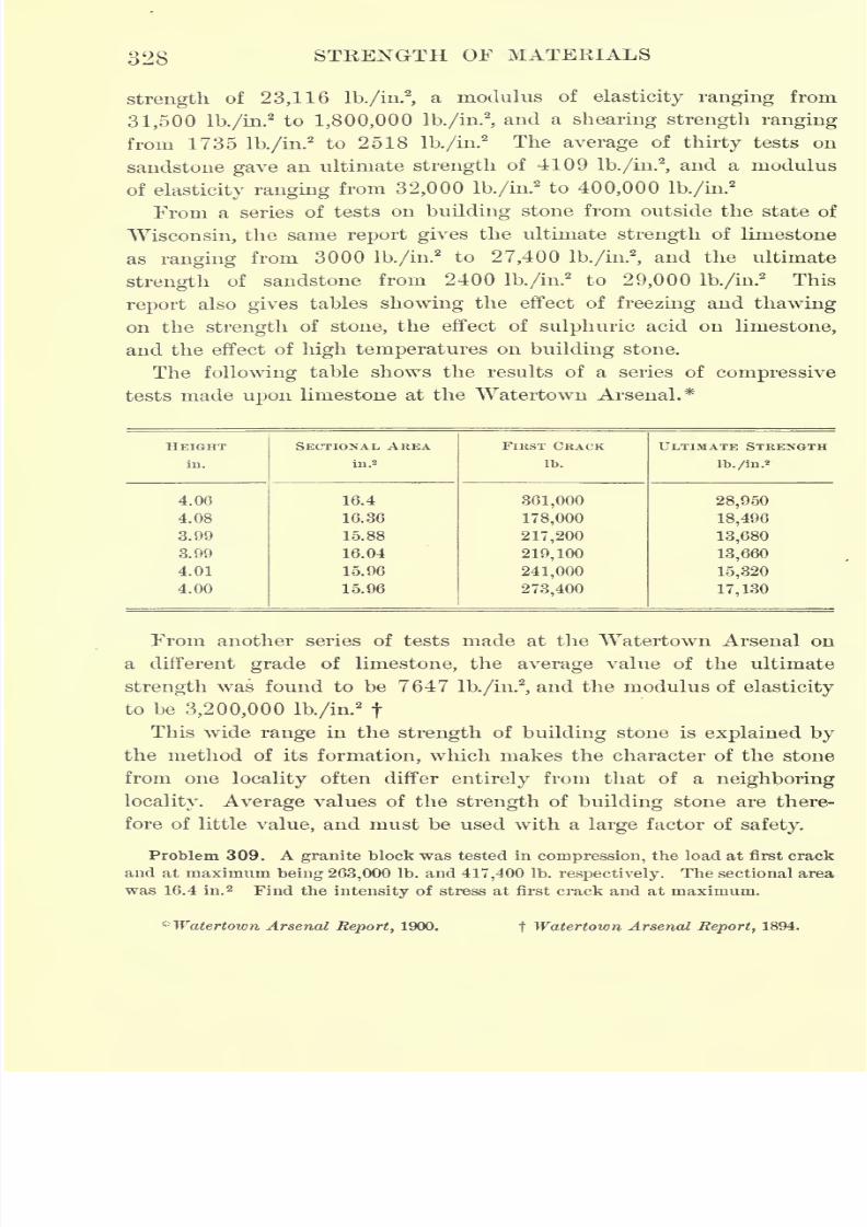
7/30/2019 Textbook on Streng 00 Slo Crich
http://slidepdf.com/reader/full/textbook-on-streng-00-slo-crich 376/433
328 STRENGTH OF MATERIALS
strength of 23,116 lb./in.2
,a modulus of elasticity ranging from
31,500 lb./in.2to 1,800,000 lb./in.
2
,and a shearing strength ranging
from 1735 lb./in.2
to 2518 lb./in.2 The average of thirty tests on
sandstone gave an ultimate strength of 4109 lb./in.2
,and a modulus
of elasticity ranging from 32,000 lb./in.2to 400,000 lb./in.
2
From a series of tests on building stone from outside the state of
Wisconsin, the same report gives the ultimate strength of limestone
as ranging from 3000 lb./in.2
to 27,400 lb./in.2
,and the ultimate
strength of sandstone from 2400 lb./in.2
to 29,000 lb./in.2
This
report also gives tables showing the effect of freezing and thawing
on the strength of stone, the effect of sulphuric acid on limestone,
and the effect of high temperatures on building stone.
The following table shows the results of a series of compressive
tests made upon limestone at the Watertown Arsenal.*
HEIGHT
in.
7/30/2019 Textbook on Streng 00 Slo Crich
http://slidepdf.com/reader/full/textbook-on-streng-00-slo-crich 377/433
FIG. 188. Result of Compression
Test of Limestone
FIG. 189. Results of Compression Tests of Sandstone

7/30/2019 Textbook on Streng 00 Slo Crich
http://slidepdf.com/reader/full/textbook-on-streng-00-slo-crich 378/433
7/30/2019 Textbook on Streng 00 Slo Crich
http://slidepdf.com/reader/full/textbook-on-streng-00-slo-crich 379/433
BRICK AND BUILDING STONE 329
235. Transverse tests of stone. The use of stone where transverse
stress is applied calls for some knowledge of its transverse strength.
A stone may meet the specificationsfor crushing and yet fail
entirely
when subjected to cross bending, since a beam is in tension on one
side and in compression on the other. As stone is much stronger in
compression than in tension, it usually fails in tension under trans-
verse loading.
To test the transverse strength of stone, small beams are pre-
pared usually 1 in. square by 6 or 8 in. long. These are supported
on knife-edges resting on the platform of the testing machine, and
the load is applied at the center. Buckley reports limestone beams
1 in. x 1 in. X 6 in. to have a modulus of rupture of 2000 lb./in.2
,
and sandstone beams 1 in. x 1 in. X 4 in. to have a modulus of rupture
of 1000 lb./in.2
236. Abrasion tests of stone. The most extended series of tests
of stone iii resisting abrasion was made by Bauschinger.* Four-inch
cubes under a pressure of 4 lb./in.2were subjected to the abrasive
action of a disk having a radius of 19.5 in. and making 200 revo-
lutions per minute, upon which 20g.
of emery were fed every 10
revolutions. The loss of volume in cubic inches was as follows.
Granite 24 dry and .46 wet
Limestone 1.10"
1.41"
Sandstone . 80"
.64"
Brick 38 ".75
"
Asphalt60 "
1.62"
Abrasion tests of stone have never been standardized, and comparison
of results of different tests must be made with a full understanding
of all the conditions affecting the results.
237. Absorption tests of stone. The absorption test is made to
determine the amount of water absorbed by the dry stone. In making
the test the specimen is first heated for several hours at a tempera-
ture of 212 F., and then placed in water for about thirty hours. Theincrease in the weight of the specimen divided by its weight when
dry and multiplied by 100 gives the percentage by weight of'moisture
absorbed. This percentage for a series of tests varied, for granite,
from 1.1 to .3 ;.for limestone, from 3.6 to 1.2;and for sandstone, from
13.8 to 1.6.
* Communications, 1884.
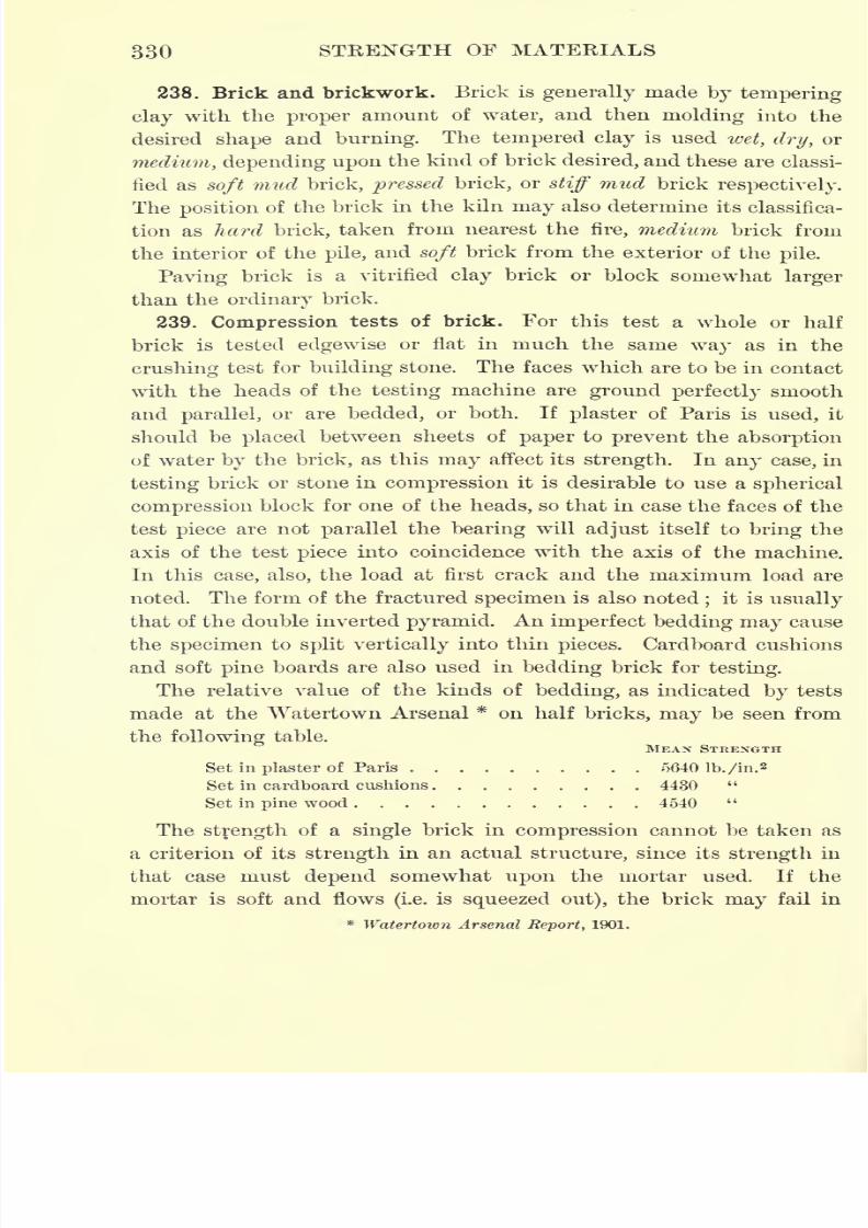
7/30/2019 Textbook on Streng 00 Slo Crich
http://slidepdf.com/reader/full/textbook-on-streng-00-slo-crich 380/433
330 STRENGTH OF MATERIALS
238. Brick and brickwork. Brick is generally made by tempering
clay with the proper amount of water, and then molding into the
desired shape and burning. The tempered clay is used wet, dry, or
medium, depending upon the kind of brick desired, and these are classi-
fied as soft mud brick, pressed brick, or stiff mud brickrespectively.
The position of the brick in the kiln may also determine its classifica-
tion as hard brick, taken from nearest the fire, medium brick from
the interior of the pile,and soft brick from the exterior of the
pile.
Paving brick is a vitrified clay brick or block somewhat larger
than the ordinary brick.
239. Compression tests of brick. For this test a whole or half
brick is tested edgewise or flat in much the same way as in the
crushing test for building stone. The faces which are to be in contact
with the heads of the testing machine are ground perfectly smooth
and parallel,or are bedded, or both. If plaster of Paris is used, it
should be placed between sheets of paper to prevent the absorption
of water by the brick, as this may affect its strength. In any case, in
testing brick or stone in compression it is desirable to use a spherical
compression block for one of the heads, so that in case the faces of the
test piece are not parallel the bearing will adjust itself to bring the
axis of the test piece into coincidence with the axis of the machine.
In this case, also, the load at first crack and the maximum load are
noted. The form of the fractured specimen is also noted;
it is usually
that of the double inverted pyramid. An imperfect bedding may cause
the specimen to split vertically into thin pieces. Cardboard cushions
and soft pine boards are also used in bedding brick for testing.
The relative value of the kinds of bedding, as indicated by tests
made at the Watertown Arsenal * on half bricks, may be seen from
the following table.MEAX STRENGTH
Set in plaster of Paris 5640 lb./in.2
Set in cardboard cushions 4430 "
Set in pine wood 4540 "
The strength of a single brick in compression cannot be taken as
a criterion of its strength in an actual structure, since its strength in
that case must depend somewhat upon the mortar used. If the
mortar is soft and flows(i.e.
is squeezed out), the brick may fail in
* Watertown Arsenal Report, 1901.
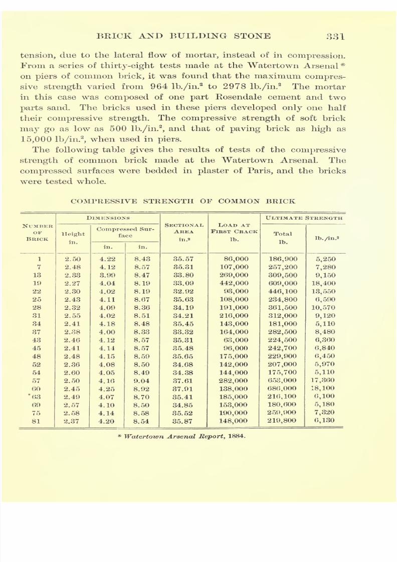
7/30/2019 Textbook on Streng 00 Slo Crich
http://slidepdf.com/reader/full/textbook-on-streng-00-slo-crich 381/433
BEICK AND BXJILDIKG STOKE 331
tension, due to the lateral flow of mortar, instead of in compression.
From a series of thirty-eight tests made at the Watertown Arsenal*
on piers of common brick, it was found that the maximum compres-
sive strength varied from 964 lb./in.2 to 2978 lb./in.
2 The mortar
in this case was composed of one part Rosendale cement and two
parts sand. The bricks used in these piers developed only one half
their compressive strength. The compressive strength of soft brick
may go as low as 500 lb./in.2
,and that of paving brick as high as
15,000 lb/in.2
,when used in piers.
The following table gives the results of tests of the compressive
strength of common brick made at the Watertown Arsenal. The
compressed surfaces were bedded in plaster of Paris, and the bricks
were tested whole.
COMPRESSIVE STRENGTH OF COMMON BRICK
NUMBER
OF
BRICK
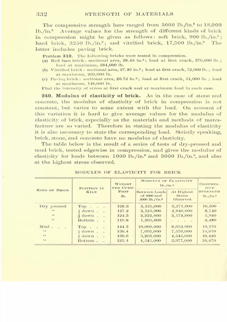
7/30/2019 Textbook on Streng 00 Slo Crich
http://slidepdf.com/reader/full/textbook-on-streng-00-slo-crich 382/433
332 STRENGTH OF MATERIALS
The compressive strength here ranged from 5000 lb./in.2to 18,000
lb./in.2
Average values for the strength of different kinds of brick
in compression might be given as follows : soft brick, 900 lb./in.'2
;
hard brick, 3250 lb./in.2
;and vitrified brick, 17,500 lb./in.
2 The
latter includes paving brick.
Problem 310. The following bricks were tested in compression.
(a)Red face brick: sectional area, 28.45 in.'
2;load at first crack, 379,000 Ib.
;
load at maximum, 384,600 Ib.
(6)Vitrified brick : sectional area, 27.46 in.
2;load at first crack, 72,000 Ib.
;load
at maximum, 230,000 Ib.
(c) Paving brick : sectional area, 26.72 in.2
;load at first crack, 51,000 Ib.
;load
at maximum, 148,000 Ib.
Find the intensity of stress at first crack and at maximum load in each case.
240. Modulus of elasticity of brick. As in the case of stone and
concrete, the modulus of elasticity of brick in compression is not
constant, but varies to some extent with the load. On account of
this variation it is hard to give average values for the modulus of
elasticity of brick, especially as the materials and methods of manu-
facture are so varied. Therefore in stating the modulus of elasticity
it is also necessary to state the corresponding load. Strictly speaking,
brick, stone, and concrete have no modulus of elasticity.
The table below is the result of a series of tests of dry-pressed and
mud brick, tested edgewise in compression, and gives the modulus of
elasticity for loads between 1000 lb./in.2and 3000 lb./in.
2
,and also
at the highest stress observed.
MODULUS OF ELASTICITY FOR BRICK
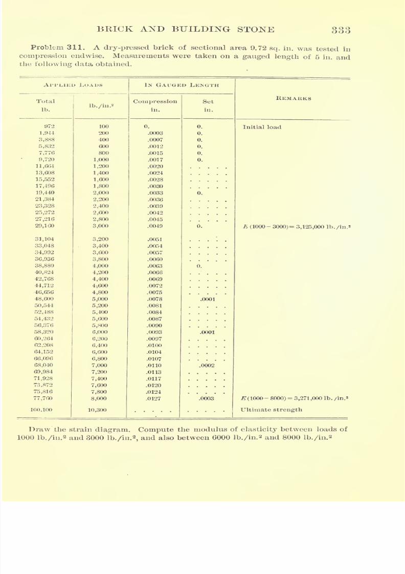
7/30/2019 Textbook on Streng 00 Slo Crich
http://slidepdf.com/reader/full/textbook-on-streng-00-slo-crich 383/433
BRICK AND BUILDING STONE 333
Problem 311. A dry-pressed brick of sectional area 9.72 sq. in. was tested in
compression endwise. Measurements were taken on a gauged length of 5 in. and
the following data obtained.
APPLIED LOADS
7/30/2019 Textbook on Streng 00 Slo Crich
http://slidepdf.com/reader/full/textbook-on-streng-00-slo-crich 384/433
334 STRENGTH OF MATERIALS
241. Transverse tests of brick. Bricks are testedtransversely
by supporting them edgewise or flatwise upon two knife-edges and
applying the load centrally by means of an ordinary testing machine.
Care must be taken to provide suitable bearing surfaces for the knife-
edges, in order to prevent local failure. In this test the upper fibers
are in compression and the lower fibers in tension, and since brick is
stronger in compression than in tension, failure is caused by rupture
of the tension face. The fiber stress is computed from the formula
Pie
P =
J>where P is the breaking load in pounds, I is the length of span in
inches, e is half the height, and I is the moment of inertia of a cross
section. The fiber stress on the outer fiber at failure is usually called
the modulus of rupture.
For paving brick the modulus of rupture varies from 1000 lb./in.2
to 3000 lb./in.2
For pressed brick, common brick, and medium brick
the modulus of rupture varies from 300 lb./in.2 to 1200 lb./in.
2
The shearing strength of various grades of brick varies from
300 lb./in.2to 2000 lb./in.
2
Problem 312. A brick having a depth of 2.23 in. and a breadth of 3.95 in. was
loaded centrally on a span of 6 in. The ultimate load was 1645 Ib. Find the
modulus of rupture.
242. Rattler test of brick.
Paving
bricks wereformerly
tested in
abrasion in order to determine their ability to withstand wear. This
test, however, does not approach the conditions of actual service,
which consist of the impact of horses' feet as well as the abrasive
action of traffic. To meet these conditions the rattler test was devised.
The testing machine consists of a cast-iron barrel mounted horizon-
tally, and the test is made by placing the brick, together with some
harder material, such as cast iron, in the machine andrevolving
it at a certain speed for a certain length of time. The ratio of the
amount of material broken or worn off in this way to the original
weight of the brick put into the machine indicates the value of the
brick in withstanding the conditions of service.
The charge usually consists of nine paving bricks or twelve other
bricks, together with 300 Ib. of cast-iron blocks, the volume of the
7/30/2019 Textbook on Streng 00 Slo Crich
http://slidepdf.com/reader/full/textbook-on-streng-00-slo-crich 385/433
BRICK AND BUILDING STONE 335
bricks being equal to about 8 per cent of the volume of the machine.
The cast-iron blocks are of two sizes, the larger being about 2J- in.
square and4J-
in. long, with rounded edges and weighing at first
7J-Ib. The smaller are about
IJ-in. cubes, with rounded edges. About
225 Ib. of the smaller size and 75 Ib. of the larger size are used;
1800 revolutions are required, and must be made at the rate of about
30 per minute.*
During the first 600 revolutions the effect of the rattler action on
the brick is to chip off the corners and edges. Thereafter the action
is morenearly
abrasive.
243. Absorption test of brick. A brick which absorbs a great
amount of water is likely to be weakened and injured by frost. To
measure the amount of absorption, a dry brick is taken and a deter-
mination of its absorbing capacity made, as in the case of stone
(Article 237).
Ordinary brick will absorb from 10 to 20 per cent of its own
weight,
andpaving
brick from 2 to 3
per
cent.
This test is now little used, since a brick that fails in the absorp-
tion test is of such poor quality that it will also fail when subjected
to the crushing and cross-bending tests.
* See specifications of the National Brick Manufacturers' Association for rattler test.
7/30/2019 Textbook on Streng 00 Slo Crich
http://slidepdf.com/reader/full/textbook-on-streng-00-slo-crich 386/433
CHAPTER XVI
TIMBER
244. Structure of timber. An examination of the cross section of
a tree usually shows that it is made up of a rather dark interior core,
or heartwood, and a lighter exterior portion, or sapwood, surrounded by
the bark. In some species, such as the oaks, radial lines, called
medullary rays, are seen running from the center toward the bark.
If the cross section happens to be near a knot or other defect, this
normal structure may be changed. If, however, no knots are present,
a closer examination shows that both the sapwood and heartwood are
made up of concentric rings, called annual rings, and that this appear-
ance is due to a difference in structure. Part of the ring is seen to
be denser than the rest, and, in fact, it is this difference in density
which gives the section its characteristic appearance.
The annual rings in one stick of a certain species may be more
widely separated than those in another stick of the same species, and
the relative thickness of heartwood and sapwood may differ in different
sticks. This indicates that the structure of timber varies considerably,
and that therefore the physical properties also vary. This wide varia-
tion is seen in all substances found in nature, one instance of which
has been shown in the case of natural stone. An investigation of the
physical properties of such substances, therefore, is more difficult than
that of a more homogeneous substance. However, the extensive use
of timber as a structural material makes a knowledge of its structure
and properties of the utmost importance.
245. Annual rings. Each of the concentric rings in timber repre-
sents the growth of one year. The inner or less dense portion repre-
sents the more rapid spring growth, while the outer dense portion
represents the slower summer and fall growth. The number of rings
per inch indicates the rate of growth for that number of years. If
the number of rings per inch be few, the growth has been rapid and
336
7/30/2019 Textbook on Streng 00 Slo Crich
http://slidepdf.com/reader/full/textbook-on-streng-00-slo-crich 387/433
TIMBER 337
the spring growth predominates, making the wood somewhat weak.
If, on the contrary, the number of rings per inch be many, a slow
growthis indicated and there is a
greater
amount of thedense, strong
summer and fall wood. The number and character of the annual
rings may thus give some idea of the strength of a piece of timber.
246. Heartwood and sapwood. The heartwood of a tree may be
considered a lifeless conical core, which is increased each year by the
addition of a portion of the outer sapwood. Both the sapwood and
heartwood contain small tubes that extend from the roots of the tree
to the branches. These tubes in the
sapwood carrywater
chargedwith nourishment to the branches and growing parts of the tree. In
the heartwood the tubes no longer act as conveyors, although they
still contain moisture. The heartwood is the mature wood and is
more valuable for structural purposes.
247. Effect of moisture. It is well known that green wood is not
as strong as the same wood when seasoned, which indicates that the
effect of moisture in timber is to lessen its
strength. Alive tree as
it stands in the forest contains a great deal of moisture. When it
has been cut, sawed, and dried, most of this moisture has evaporated,
but considerable still remains, and however well seasoned timber may
be, it will still contain some moisture.
In making tests of timber, therefore, it is necessary to determine
the percentage of moisture in order that the results- may be compared
with theresults of other tests. This is
determined by cuttinga
small piece from the uninjured portion of the test piece and weighing
before and after thorough drying. The difference in weight divided
by the dry weight and multiplied by 100 gives the percentage of
moisture.
248. Strength of timber. The strength of timber depends upon the
amount of heartwood or sapwood, knots (sound orloose),
wind shakes
and checks, cracks, or any defect that breaks the continuityof the
fiber. In general, the strength of timber is indicated by its weight,
the heaviest timbers being the strongest. Timber is strongest along the
grain both in tension and compression, as will be seen in what follows.
It has been found that values obtained for the strength of timber
by testing small, carefully selected test pieces are much higher than
those obtained by testing large commercial timbers. This is what
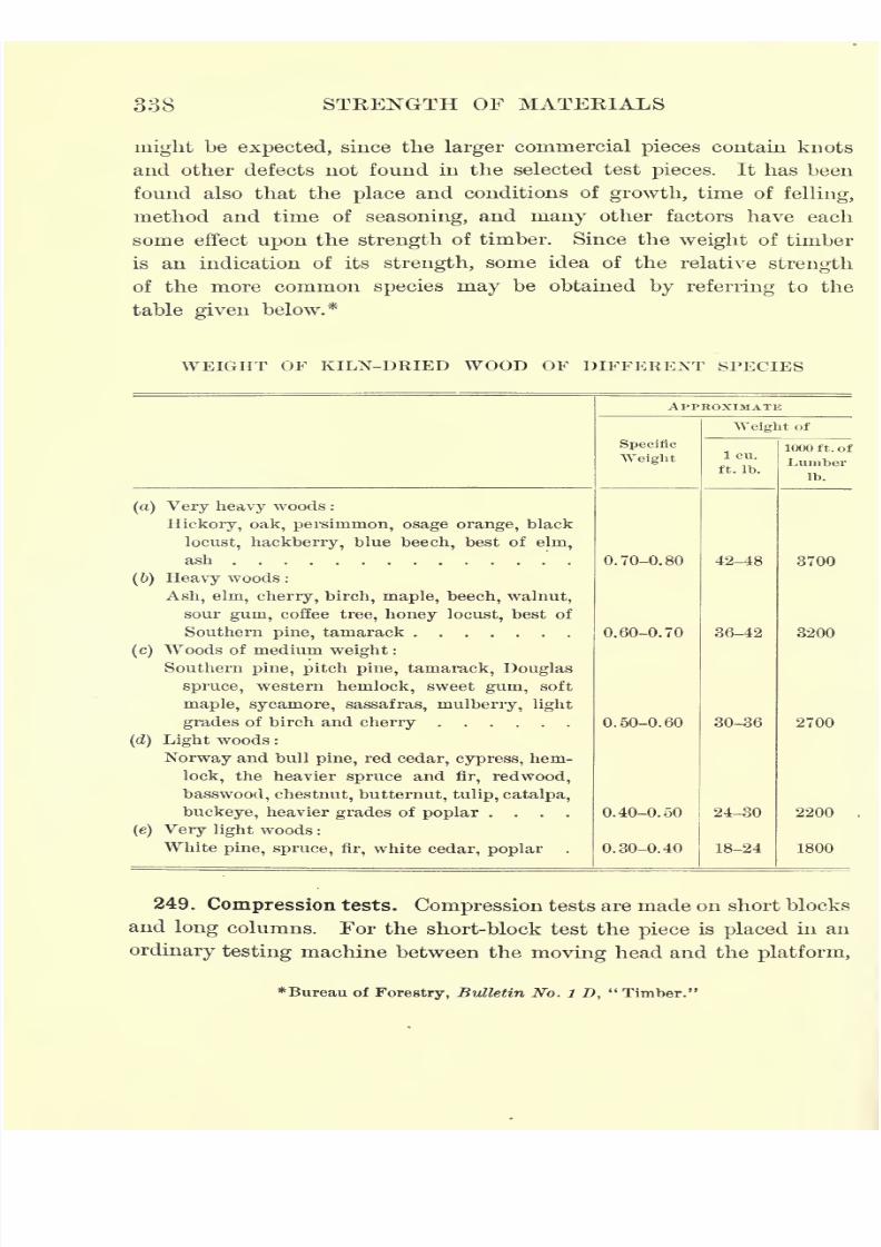
7/30/2019 Textbook on Streng 00 Slo Crich
http://slidepdf.com/reader/full/textbook-on-streng-00-slo-crich 388/433
338 STRENGTH OF MATERIALS
might be expected, since the larger commercial pieces contain knots
and other defects not found in the selected test pieces. It has been
found also that theplace
and conditions of
growth,time of
felling,method and time of seasoning, and many other factors have each
some effect upon the strength of timber. Since the weight of timber
is an indication of its strength, some idea of the relative strength
of the more common species may be obtained by referring to the
table given below.*
WEIGHT OF KILN-DRIED WOOD OF DIFFERENT SPECIES
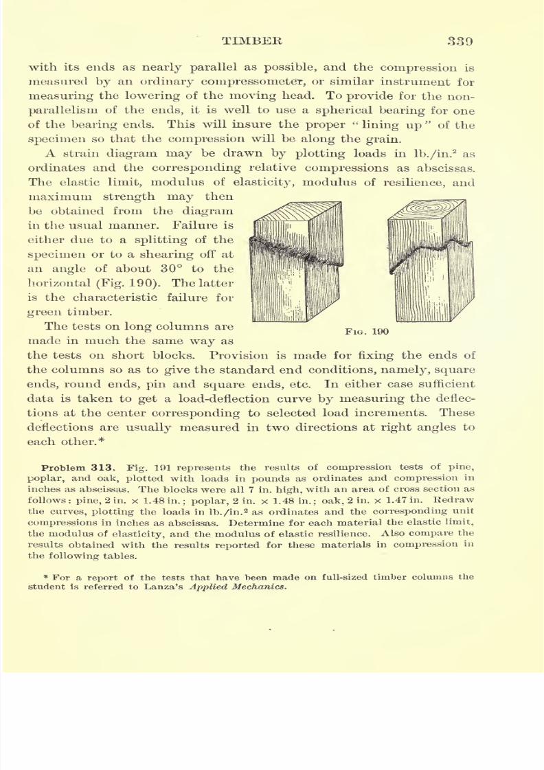
7/30/2019 Textbook on Streng 00 Slo Crich
http://slidepdf.com/reader/full/textbook-on-streng-00-slo-crich 389/433
TIMBER 339
with its ends as nearly parallel as possible, and the compression is
measured by an ordinary compressornet6T, or similar instrument for
measuringthe
loweringof the
movinghead.
To provide for the non-
parallelism of the ends, it is well to use a spherical bearing for one
of the bearing ends. This will insure the proper"lining up
"of the
specimen so that the compression will be along the grain.
A strain diagram may be drawn by plotting loads in lb./in.2as
ordinates and the corresponding relative compressions as abscissas.
The elastic limit, modulus of elasticity, modulus of resilience, and
maximum strength may thenbe obtained from the diagram
in the usual manner. Failure is
either due to a splitting of the
specimen or to a shearing off at
an angle of about 30 to the
horizontal(Fig. 190). The latter
is the characteristic failure for
green timber.
The tests on long columns are
made in much the same way as
the tests on short blocks. Provision is made for fixing the ends of
the columns so as to give the standard end conditions, namely, square
ends, round ends, pin and square ends, etc. In either case sufficient
data is taken to get a load-deflection curve by measuring the deflec-
tions at the center corresponding to selected load increments. These
deflections are usually measured in two directions at right angles to
each other.*
Problem 313. Fig. 191 represents the results of compression tests of pine,
poplar, and oak, plotted with loads in pounds as ordinates and compression in
inches as abscissas. The blocks were all 7 in. high, with an area of cross section as
follows:
pine, 2 in. x 1.48 in. ; poplar, 2 in. x 1.48 in. ; oak, 2 in. x 1.47 in. Redrawthe curves, plotting the loads in lb./in.
2 as ordinates and the corresponding unit
compressions in inches as abscissas. Determine for each material the elastic limit,
the modulus of elasticity, and the modulus of elastic resilience. Also compare the
results obtained with the results reported for these materials in compression in
the following tables.
FIG. 190
* For a report of the tests that have been made on full-sized timber columns the
student is referred to Lanza's Applied Mechanics.
7/30/2019 Textbook on Streng 00 Slo Crich
http://slidepdf.com/reader/full/textbook-on-streng-00-slo-crich 390/433
340 STRENGTH OF MATERIALS
250. Flexure tests. Flexure tests are usually made by supporting
a rectangular piece at both ends and loading it in the middle, care
beingtaken to
guard against
local failure at the
supports
and at the
point of application of the load. This local failure may be prevented
by inserting some kind of metal plate between the beam and the
knife-edge. The deflections of the beam for specified loads are meas-
ured by means of a deflectorneter, usually measuring to .01 in. or
.001 in. From the data obtained from a test, a strain diagram may
be drawn by plotting loads in pounds as ordinates and deflections in
inches as abscissas. The fiber stress for
anyload within the elastic
limit is determined, for central loading, from the formula
PieP =
I>
and the modulus of elasticity from the formula (Article 67)
,**-.4:8 DI
The formulas used to determine the fiber stress in the case of the
flexure of beams(
= J/max )are true only within the elastic limit
e
of the material. They are used, however, to determine the fiber stress
beyond the elastic limit, although they are only approximately true
beyond this limit. The value of the fiber stress at rupture as deter-
minedby
the formula is
usually designatedas the modulus of
rupture
(Article 65) ;it is expressed in lb./in.
2
On account of the peculiar structure of timber the character of
the fracture due to a failure in flexure is rather difficult to predict.
In case the specimen is free from knots and the grain is parallel to the
length of the piece, failure from concentrated central loading is likely
to take place either on the tension or the compression side, or both.
It
may happen, however,even in the case of such a
perfect specimenas
indicated, that failure will be due to horizontal shear. In such cases
shearing takes place along the spring growth of one of the annual
rings. This may have been weakened previously by wind shakes.
If part of the beam is sapwood and part heartwood, the fracture
will be influenced thereby, due to the difference in the strength of
the two portions. A cross grain may cause a failure due to splitting.
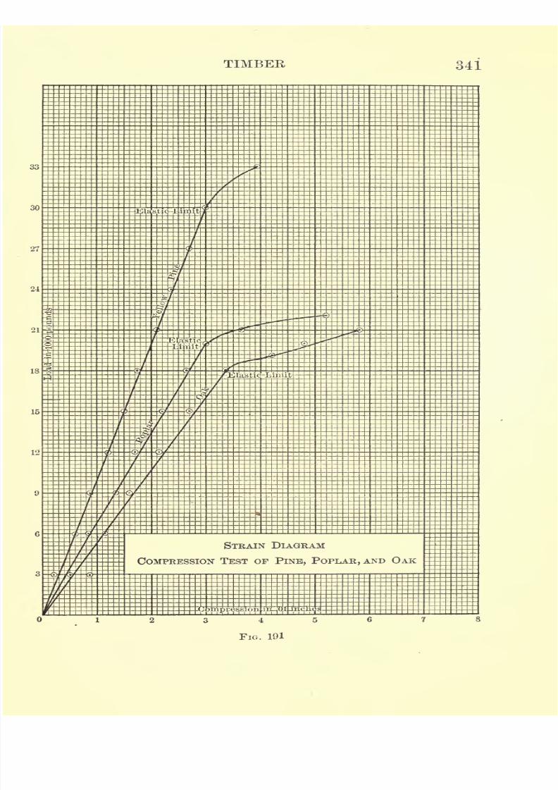
7/30/2019 Textbook on Streng 00 Slo Crich
http://slidepdf.com/reader/full/textbook-on-streng-00-slo-crich 391/433
TIMBER 341
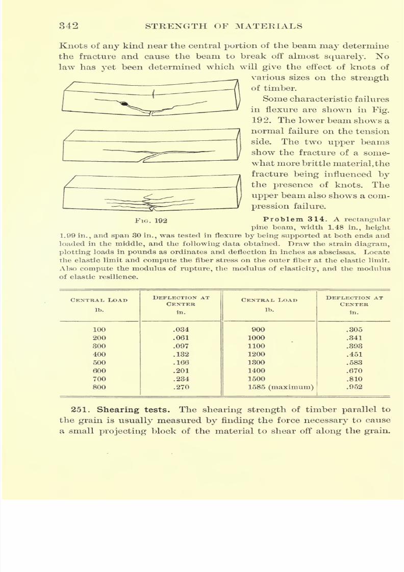
7/30/2019 Textbook on Streng 00 Slo Crich
http://slidepdf.com/reader/full/textbook-on-streng-00-slo-crich 392/433
342 STRENGTH OF MATERIALS
Knots of any kind near the central portion of the beam may determine
the fracture and cause the beam to break off almost squarely. No
law has yet been determined which will give the effect of knots of
various sizes on the strength
of timber.
Some characteristic failures
in flexure are shown in Fig.
192. The lower beam shows a
normal failure on the tension
side. The two upper beams
show the fracture of a some-
what more brittle material,the
fracture being influenced by
the presence of knots. The
upper beam also shows a com-
pression failure.
FIG. 192 Problem 314. A rectangular
pine beam, width 1.48 in., height
1.99 in., and span 30 in., was tested in flexure by being supported at both ends and
loaded in the middle, and the following data obtained. Draw the strain diagram,
plotting loads in pounds as ordinates and deflection in inches as abscissas. Locate
the elastic limit and compute the fiber stress on the outer fiber at the elastic limit.
Also compute the modulus of rapture, the modulus of elasticity, and the modulus
of elastic resilience.
CENTRAL LOAD
Ib.
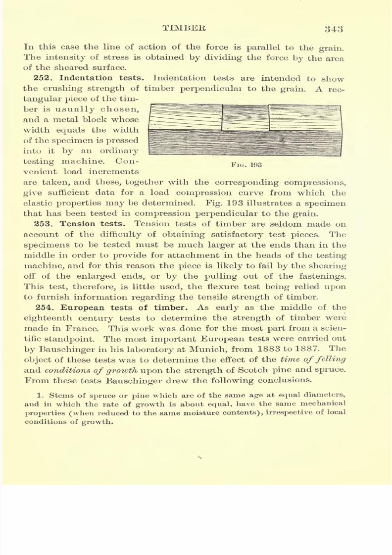
7/30/2019 Textbook on Streng 00 Slo Crich
http://slidepdf.com/reader/full/textbook-on-streng-00-slo-crich 393/433
T1MBEB, 343
In this case the line of action of the force is parallel to the grain.
The intensity of stress is obtained by dividing the force by the area
of the sheared surface.
252. Indentation tests. Indentation tests are intended to show
the crushing strength of timber perpendicular to the grain. A rec-
tangular piece of the tim-
ber is usually chosen,
and a metal block whose
width equals the width
of thespecimen
is
pressedinto it by an ordinary
testing machine. Con-FIG 193
venient load increments
are taken, and these, together with the corresponding compressions,
give sufficient data for a load compression curve from which the
elastic properties may be determined. Fig. 193 illustrates a specimen
that has been tested in
compression perpendicularto the
grain.253. Tension tests. Tension tests of timber are seldom made on
account of the difficulty of obtaining satisfactory test pieces. The
specimens to be tested must be much larger at the ends than in the
middle in order to provide for attachment in the heads of the testing
machine, and for this reason the piece is likely to fail by the shearing
off of the enlarged ends, or by the pulling out of the fastenings.
This test, therefore, is little used, the flexure test being relied uponto furnish information regarding the tensile strength of timber.
254. European tests of timber. As early as the middle of the
eighteenth century tests to determine the strength of timber were
made in France. This work was done for the most part from a scien-
tific standpoint. The most important European tests were carried out
by Bauschinger in his laboratory at Munich, from 1883 to 188 7. The
object of these tests was to determine the effect of the time of felling
and conditions of growth upon the strength of Scotch pine and spruce.
From these tests Bauschinger drew the following conclusions.
1. Stems of spruce or pine which are of the same age at equal diameters,
and in which the rate of growth is about equal, have the same mechanical
properties (when reduced to the same moisture contents) , irrespective of local
conditions of growth.
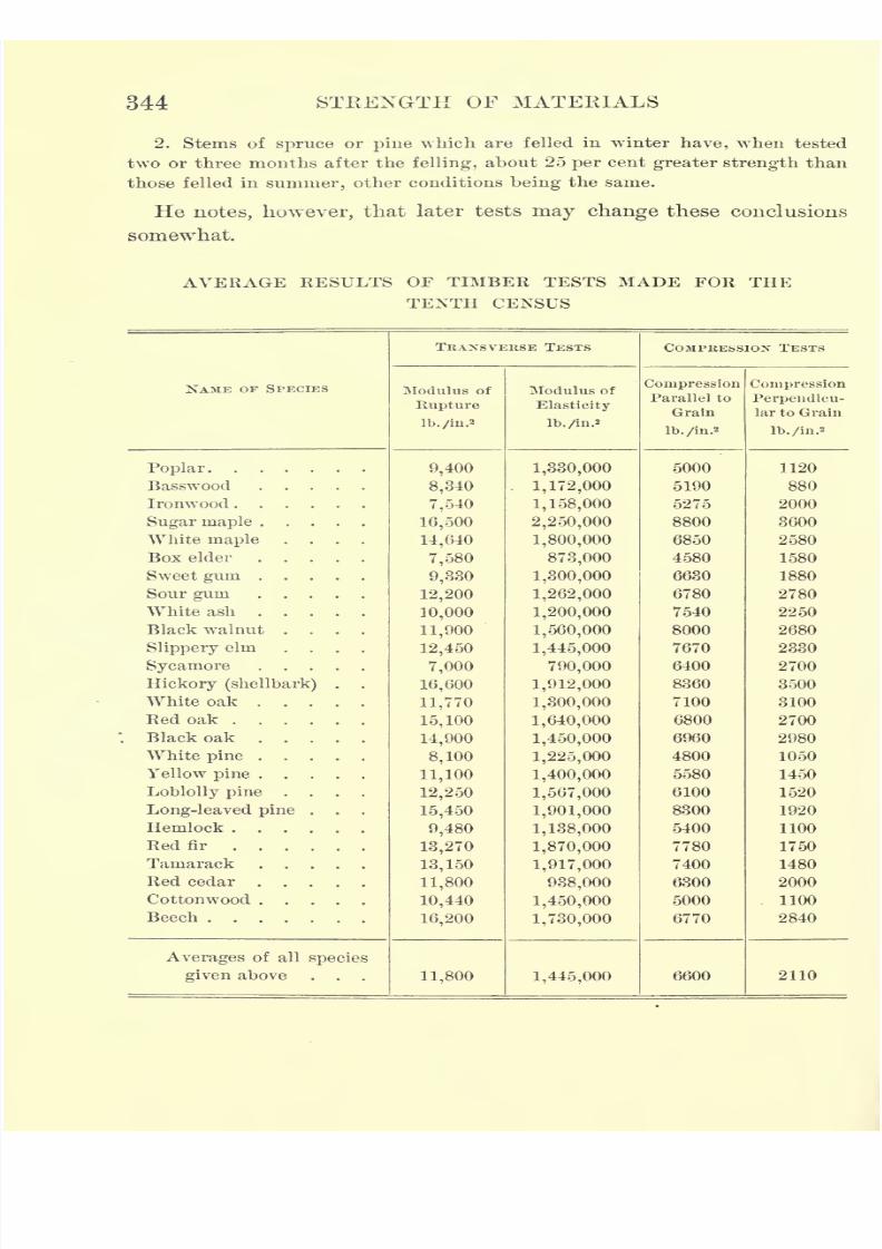
7/30/2019 Textbook on Streng 00 Slo Crich
http://slidepdf.com/reader/full/textbook-on-streng-00-slo-crich 394/433
344 STRENGTH OF MATERIALS
2. Stems of spruce or pine which are felled in winter have, when tested
two or three months after the felling, about 25 per cent greater strength than
those felled in summer, other conditions being the same.
He notes, however, that later tests may change these conclusions
somewhat.
AVERAGE RESULTS OF TIMBER TESTS MADE FOR THE
TENTH CENSUS
NAME OF SPECIES
7/30/2019 Textbook on Streng 00 Slo Crich
http://slidepdf.com/reader/full/textbook-on-streng-00-slo-crich 395/433
TIMBER 345
255. Tests made for the tenth census. In the United States, tests
were made for the tenth census on four hundred and twelve species
of timber. The test specimens were all small, selected pieces, 1.57 in.
X 1.57 in. in cross section, and 43 in. long, and were seasoned in a
dry, cool building for two years. On account of the number of
species tested the results obtained are not conclusive, but should
be taken as indicating the probable values for the strength of the
timbers tested. On page 344 is given a table of the averages for some
of the species tested. Since the test pieces were all small, selected
specimens, the results are probably higher than would have been
obtained from larger commercial specimens.
In the transverse tests the specimens were supported at both ends
and loaded in the middle, the span being 39.37 in. The compression
tests parallel to the gram were made on pieces 1.57 in. x 1.57 in. in
cross section, and 12.6 in. long. Indentation tests were made on
pieces 1.57 hi. x 1.57 in. in cross section and 6.3 in. long. The test
pieces in the latter case rested upon the platform of the testing
machine, and the tests were made by crushing perpendicular to the
grain with a plate 1.57 in. x 1.57 in. in size, by lowering the moving
head of the machine.
256. Tests made by the Bureau of Forestry. The most extensive
series of timber tests that has ever been undertaken has been begun
by the United States Department of Agriculture under the direction
of the Bureau of Forestry. These tests were begun in 1891, under
the direction of Professor J. B. Johnson, at St. Louis. Thirty-two
species were tested and 45,000 tests were made. The material was
selected with special reference to the conditions under which the
trees were grown, and the test pieces were small, selected speci-
mens. The table on page 346 gives the average results of some of
the tests.*
In the table the results have been reduced to an amount of moist-
ure equivalent to 12 per cent of the dry weight.
A comparison of this table with that of the tenth census shows as
close an Agreement in most cases as might be reasonably expected
when the variability of timber is considered, and serves to extend
and verify the results of the previous work.
* U. S. Forestry Circular, No. 15.
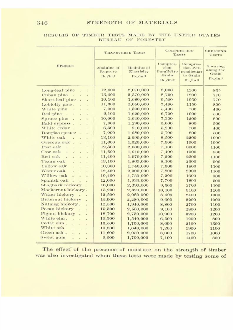
7/30/2019 Textbook on Streng 00 Slo Crich
http://slidepdf.com/reader/full/textbook-on-streng-00-slo-crich 396/433
346 STRENGTH OF MATERIALS
RESULTS OF TIMBER TESTS MADE BY THE UNITED STATESBUREAU OF FORESTRY
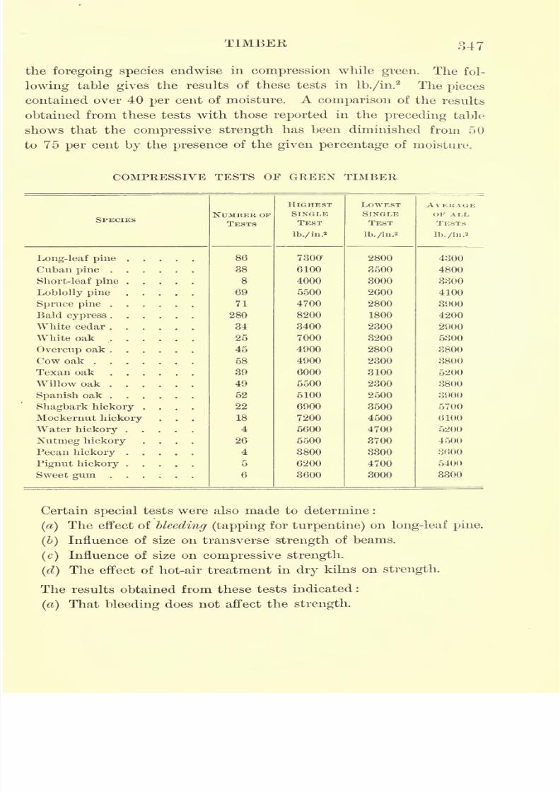
7/30/2019 Textbook on Streng 00 Slo Crich
http://slidepdf.com/reader/full/textbook-on-streng-00-slo-crich 397/433
TIMBER 347
the foregoing species endwise in compression while green. The fol-
lowing table gives the results of these tests in lb./in.2
The pieces
contained over 40 per cent of moisture. A comparison of the results
obtained from these tests with those reported in the preceding table
shows that the compressive strength has been diminished from 50
to 75 per cent by the presence of the given percentage of moisture.
COMPRESSIVE TESTS OF GREEN TIMBER
SPECIES
7/30/2019 Textbook on Streng 00 Slo Crich
http://slidepdf.com/reader/full/textbook-on-streng-00-slo-crich 398/433
348 STRENGTH OF MATERIALS
(&)That large, sound beams may be as strong as small ones cut
from the same piece ;that is, large beams may show the same fiber
stress as small ones.
(c)That large, sound pieces in compression may be as strong as
small ones cut from the same piece; that is, the intensity of com-
pressive stress may be the same.
(d)That there were no detrimental effects.
The results of the tests made by the Bureau of Forestry, as out-
lined in this article, should not be taken as conclusive, since not a
sufficient
numberof tests were made to establish values. The
pieceswere in most cases small, and specially selected, and the results are
of more value from a scientific than from a commercial standpoint,
since the lumber of commerce contains knots, wind shakes, and other
defects that lessen its strength.
257. Recent work of the United States Forest Service. The United
States Forest Service (formerly known as the Bureau of Forestry)
hasrecently
made extensive studies of the usesand durability
of
the various commercial woods of the United States, and has also
conducted a series of tests to determine their strength, the most im-
portant of which are as follows :
() Tests of commercial-size beams of various timbers found on the market
to determine
1. The effect of knots and other defects on the strength.
2. The effect of moisture on the strength.
3. The effect of preservatives on the strength.
4. The effect of methods of seasoning on the strength.
(&) Tests of materials used in the construction for vehicles for such pur-
poses as spokes, axles, and poles,
(c) Tests of the strength of packing boxes.
(d} Tests of the strength of railroad ties.
In each of theseinvestigations
one of theobjects
has been to deter-
mine, if possible, some so-called inferior woods that might be used in
place of varieties that are superior but are becoming scarce. The test
pieces for(a) were large commercial pieces in which knots and other
defects occur, as they do in the structural timbers used by engineers.
A summary of some of the cross-bending tests is given in the
following table.
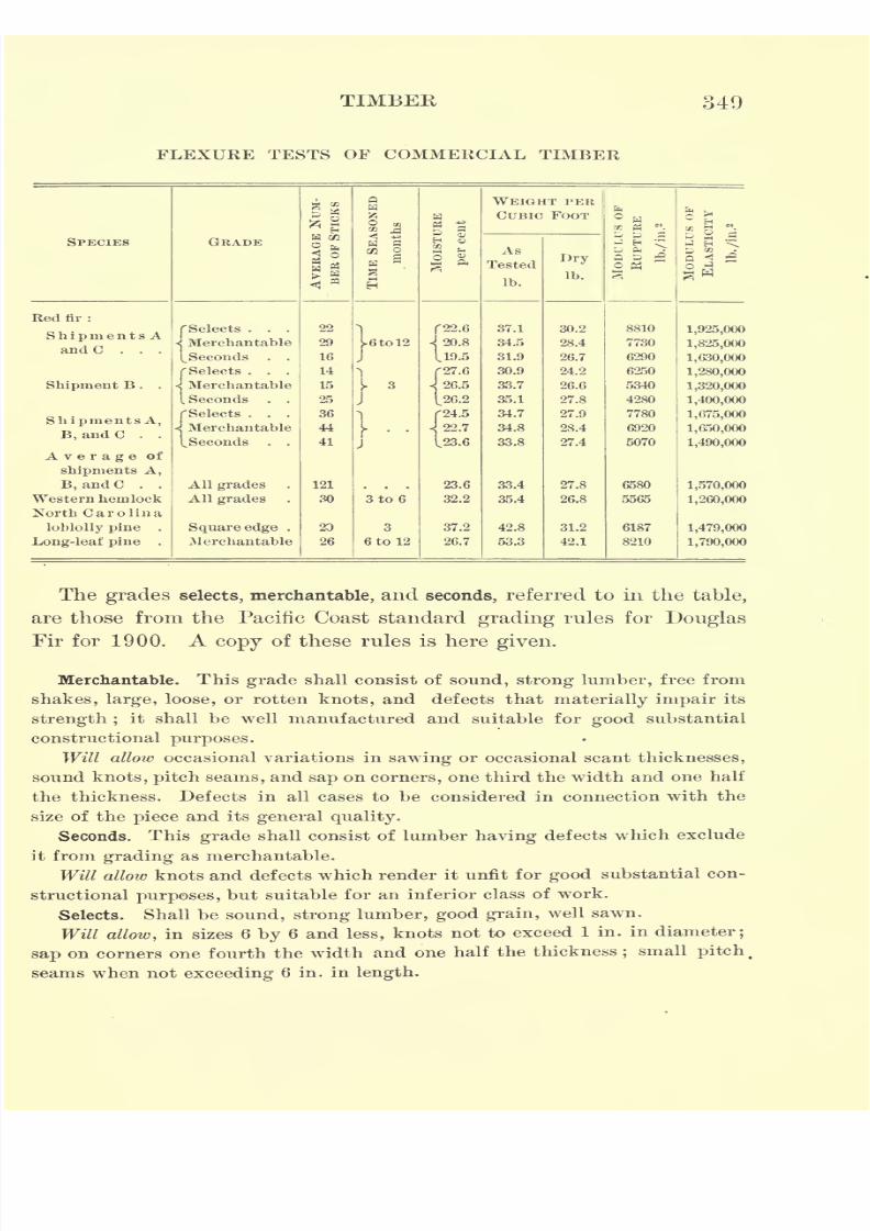
7/30/2019 Textbook on Streng 00 Slo Crich
http://slidepdf.com/reader/full/textbook-on-streng-00-slo-crich 399/433
TIMBEK 349
FLEXURE TESTS OF COMMERCIAL TIMBER

7/30/2019 Textbook on Streng 00 Slo Crich
http://slidepdf.com/reader/full/textbook-on-streng-00-slo-crich 400/433
350 STRENGTH OF MATERIALS
114CCrf
00 >*
Oa,
S C mr. o x~ 51^ f ^V- ~
; ^ x i
1.2
JC^
00 5<1.
CD 00 C<1 . OOOCO .00 C<1
.O 00 O5 . OOC<I
. OOCO .r< T)H 00 00 C<1
. Clib
XX .XXX .XXX .XX .XXX .XX .XX .XXXXX .XX
Sr-'
feo S858
11
0005
X X
X X
5oci
X X .
3 o
* .2-a -S
.2
^H r^
a 5 -a
S S a
S'o
.S O .X
"25
*il
O o
IJ
as aa
'a Ht>, O
s o -3 o ^3 oI r2 -- n "T<
11 3*1
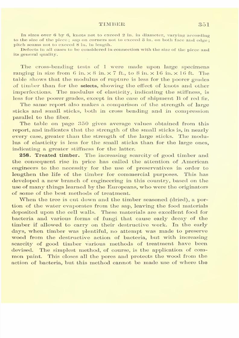
7/30/2019 Textbook on Streng 00 Slo Crich
http://slidepdf.com/reader/full/textbook-on-streng-00-slo-crich 401/433
TIMBER 351
In sizes over 6 by 6, knots not to exceed 2 in. in diameter, varying according
to the size of the piece ; sap on corners not to exceed 3 in. on both face and edge ;
pitch seams not to exceed 8 in. in length.
Defects in all cases to be considered in connection with the size of thepiece
and
its general quality.
The cross-bending tests of 1 were made upon large specimens
ranging in size from 6 in. x 8 in. x 7 ft., to 8 in. x 16 in. x 16 ft. The
table shows that the modulus of rupture is less for the poorer grades
of timber than for the selects, showing the effect of knots and other
imperfections. The modulus ofelasticity, indicating the stiffness, is
less for the poorer grades, except in the case of shipment B of red fir.
The same report also makes a comparison of the strength of large
sticks and small sticks, both in cross bending and in compression
parallel to the fiber.
The table on page 350 gives average values obtained from this
report, and indicates that the strength of the small sticks is, in nearly
every case, greater than the strength of the large sticks. The modu-
lus of elasticity is less for the small sticks than for the large ones,
indicating a greater stiffness for the latter.
258. Treated timber. The increasing scarcity of good timber and
the consequent rise in price has called the attention of American
engineers to the necessity for the use of preservatives in order to
lengthen the life of the timber for commercial purposes. This has
developed a new branch of engineering in this country, based on the
use of many things learned by the Europeans, who were the originators
of some of the best methods of treatment.
When the tree is cut down and the timber seasoned (dried), a por-
tion of the water evaporates from the sap, leaving the food materials
deposited upon the cell walls. These materials are excellent food for
bacteria and various forms of fungi that cause early decay of the
timber if allowed to carry on their destructive work. In the early
days, when timber was plentiful, no attempt was made to preserve
wood from the destructive action of bacteria, but with increasing
scarcity of good timber various methods of treatment have been
devised. The simplest method, of course, is the application of com-
mon paint. This closes all the pores and protects the wood from the
action of bacteria, but this method cannot be made use of where the
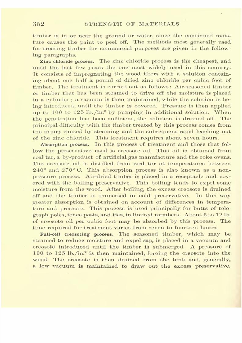
7/30/2019 Textbook on Streng 00 Slo Crich
http://slidepdf.com/reader/full/textbook-on-streng-00-slo-crich 402/433
352 STRENGTH OF MATERIALS
timber is in or near the ground or water, since the continued mois-
ture causes the paint to peel off. The methods most generally used
for treating timber for commercial purposes are given in the follow-
ing paragraphs.
Zinc chloride process. The zinc chloride process is the cheapest, and
until the last few years the one most widely used in this country.
It consists of impregnating the wood fibers with a solution contain-
ing about one half a pound of dried zinc chloride per cubic foot of
timber. The treatment is carried out as follows : Air-seasoned timber
or timber that has been steamed to drive off the moisture is placed
in a cylinder ;a vacuum is then maintained, while the solution is be-
ing introduced, until the timber is covered. Pressure is then applied
up to 100 to 125 lb./in.2
by pumping in additional solution. When
the penetration has been sufficient, the solution is drained off. The
principal difficulty with the timber treated by this process comes from
the injury caused by steaming and the subsequent rapid leaching out
of the zinc chloride. This treatment requires about seven hours.
Absorption process. In this process of treatment and those that fol-
low the preservative used is creosote oil. This oil is obtained from
coal tar, a by-product of artificial gas manufacture and the coke ovens.
The creosote oil is distilled from coal tar at temperatures between
240 and 270 C. This absorption process is also known as a non-
pressure process. Air-dried timber is placed in a receptacle and cov-
ered with the boiling preservative. This boiling tends to expel some
moisture from the wood. After boiling, the excess creosote is drained
off and the timber is immersed in cold preservative. In this way
greater absorption is obtained on account of differences in tempera-
ture and pressure. This process is used principally for butts of tele-
graph poles, fence posts, and ties, in limited numbers. About 6 to 12 Ib.
of creosote oil per cubic foot may be absorbed by this process. The
time required for treatment varies from seven to fourteen hours.
Full-cell creosoting process. The seasoned timber, which may be
steamed to reduce moisture and expel sap, is placed in a vacuum and
creosote introduced until the timber is submerged. A pressure of
100 to 125 lb./in.2
is then maintained, forcing the creosote into the
wood. The creosote is then drained from the tank and, generally,
a low vacuum is maintained to draw out the excess preservative.
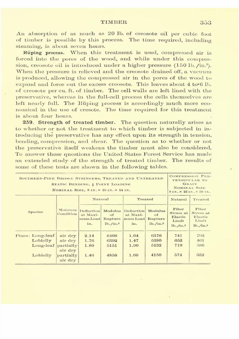
7/30/2019 Textbook on Streng 00 Slo Crich
http://slidepdf.com/reader/full/textbook-on-streng-00-slo-crich 403/433
TIMBER 353
An absorption of as much as 20 Ib. of creosote oil per cubic foot
of timber is possible by this process. The time required, including
steaming, is about seven hours.
Riiping process. When this treatment is used, compressed air is
forced into the pores of the wood, and while under this compres-
sion, creosote oil is introduced under a higher pressure (150 lb./in.2
).
When the pressure is relieved and the creosote drained off, a vacuum
is produced, allowing the compressed air in the pores of the wood to
expand and force out the excess creosote. This leaves about 4 to%6 Ib.
of creosote per cu. ft. of timber. The cell walls are left lined with the
preservative, whereas in the full-cell process the cells themselves are
left nearly full. The Iviiping process is accordingly much more eco-
nomical in the use of cresote. The time required for this treatment
is about four hours.
259. Strength of treated timber. The question naturally arises as
to whether or not the treatment to which timber is subjected in in-
troducing the preservative has any effect upon its strength in tension,
bending, compression, and shear. The question as to whether or not
the preservative itself weakens the timber must also be considered.
To answer these questions the United States Forest Service has made
an extended study of the strength of treated timber. The results of
some of these tests are shown in the following tables.
SOUTHERN-PlNE BRIDGE STRINGERS, TREATED AND UNTREATED
STATIC BENDING, $ POINT LOADING
NOMINAL SIZE, 8 IN. x IG IN. x 14 IN.
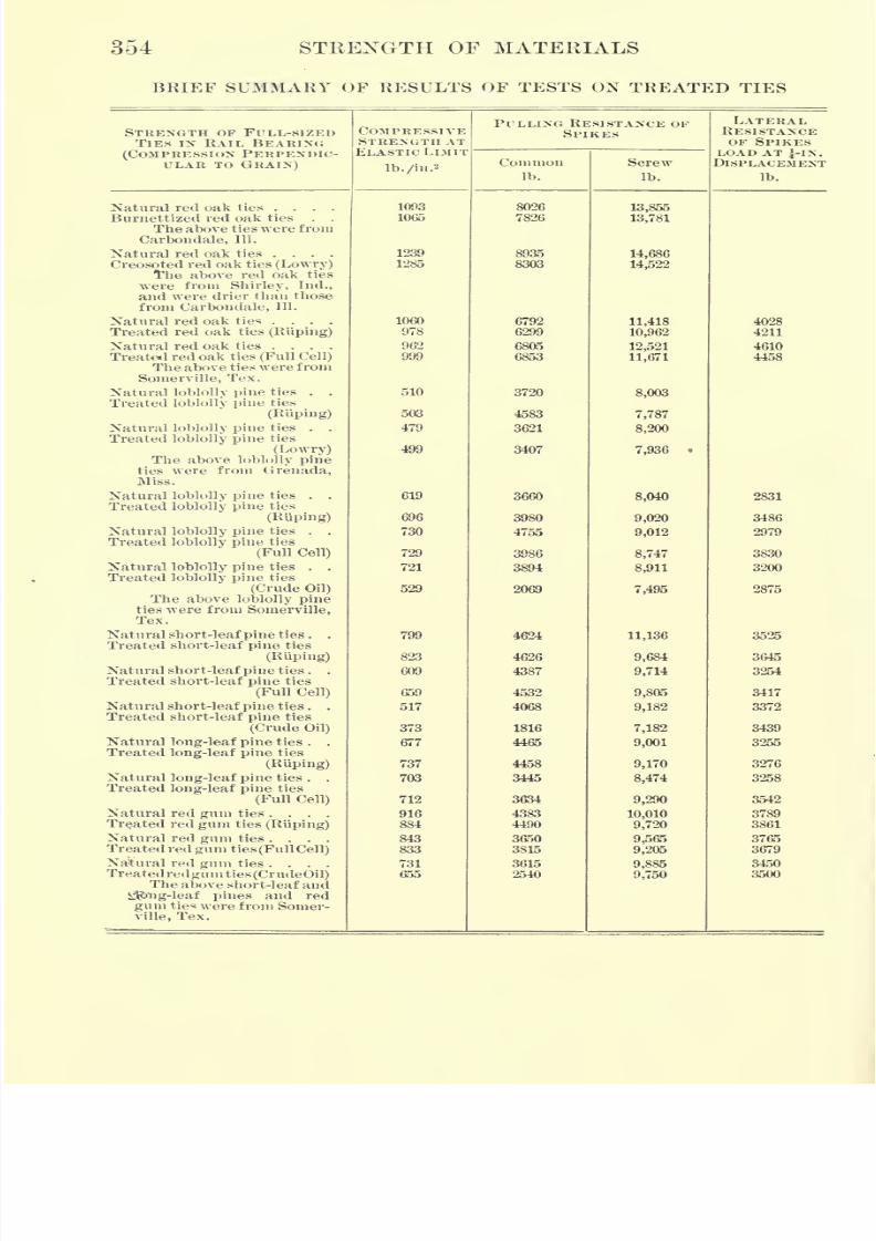
7/30/2019 Textbook on Streng 00 Slo Crich
http://slidepdf.com/reader/full/textbook-on-streng-00-slo-crich 404/433
354 STRENGTH OF MATERIALS
BRIEF SUMMARY OF RESULTS OF TESTS ON TREATED TIES
STRENGTH OF FULL-SIZEDTIES ix RAIL BEARING
(COMPRESSION PERPENDIC-
ULAR TO GRAIN)
7/30/2019 Textbook on Streng 00 Slo Crich
http://slidepdf.com/reader/full/textbook-on-streng-00-slo-crich 405/433
TIMBER 355
An examination of the results of tests of the bridge stringers shows
that there is little decrease in strength due to the action of the creo-
sote in the case of the air-dry, long-leaf pine. The loblolly pine, air
dried, shows a decrease in strength of 16 per cent in bending and
29 per cent in compression. The long-leaf pine, partially air dried,
shows no appreciable decrease in strength in bending, but about 18
per cent decrease in compression. Loblolly pine, partially air dried,
shows 14 per cent decrease in bending strength and 38 per cent in
compressive strength. These tests seem to show that long-leaf pine
is injured very little, if any, by the creosote, while loblolly pine is
injured appreciably. Treated oak ties (results not given here) show
a decrease in strength of from 5 to 10 per cent. Douglas fir and
Wisconsin white pine show little or no effect due to treatment so far
as bending and compression are concerned, but show a decrease in
strength of from 20 to 25 per cent in shear.
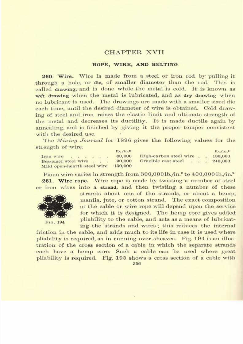
7/30/2019 Textbook on Streng 00 Slo Crich
http://slidepdf.com/reader/full/textbook-on-streng-00-slo-crich 406/433
CHAPTER XVII
ROPE, WIRE, AND BELTING
260. Wire. Wire is made from a steel or iron rod by pulling it
through a hole, or die, of smaller diameter than the rod. This is
called drawing, and is done while the metal is cold. It is known as
wet drawing when the metal is lubricated, and as dry drawing when
no lubricant is used. The drawings are made with a smaller sized die
each time, until the desired diameter of wire is obtained. Cold draw-
ing of steel and iron raises the elastic limit and ultimate strength of
the metal and decreases its ductility. It is made ductile again by
annealing, and is finished by giving it the proper temper consistent
with the desired use.
The Mining Journal for 1896 gives the following values for the
strength of wire.
lb./in.* Ib./in-2
Iron wire 80,000 High-carbon steel wire . . 180,000
Bessemer steel wire . . . 90,000 Crucible cast steel . . . 240,000
Mild open-hearth steel wire 130,000
Piano wire varies in strength from 300,000 lb./in.2to 400,0001b./in.
2
261. Wire rope. Wire rope is made by twisting a number of steel
or iron wires into a strand, and then twisting a number of these
strands about one of the strands, or about a hemp,
manila, jute, or cotton strand. The exact composition
of the cable or wire rope will depend upon the service
for which it is designed. The hemp core gives added
pliability to the cable, and acts as a means of lubricat-
ing the strands and wires;this reduces the internal
friction in the cable, and adds much to its life in case it is used where
pliability is required, as in running over sheaves. Fig. 194 is an illus-
tration of the cross section of a cable in which the separate strands
each have a hemp core. Such a cable can be used where great
pliabilityis required. Fig. 195 shows a cross section of a cable with
356
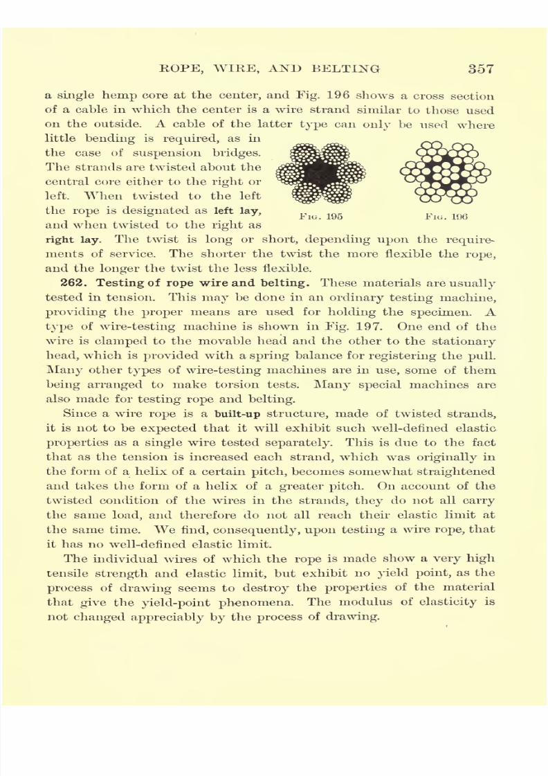
7/30/2019 Textbook on Streng 00 Slo Crich
http://slidepdf.com/reader/full/textbook-on-streng-00-slo-crich 407/433
KOPE, WIKE, AND BELTING 357
a single hemp core at the center, and Fig. 196 shows a cross section
of a cable in which the center is a wire strand similar to those used
on the outside.
Acable of the latter
typecan
only be used wherelittle bending is required, as in
the case of suspension bridges.
The strands are twisted about the
central core either to the right or
left. When twisted to the left
the rope is designated as left lay,FIG. 195 FIG. 196
and when twisted to theright
as
right lay. The twist is long or short, depending upon the require-
ments of service. The shorter the twist the more flexible the rope,
and the longer the twist the less flexible.
262. Testing of rope wire and belting. These materials are usually
tested in tension. This may be done in an ordinary testing machine,
providing the proper means are used for holding the specimen. A
typeof
wire-testingmachine is shown in
Fig.197. One end of the
wire is clamped to the movable head and the other to the stationary
head, which is provided with a spring balance for registering the pull.
Many other types of wire-testing machines are in use, some of them
being arranged to make torsion tests. Many special machines are
also made for testing rope and belting.
Since a wire rope is a built-up structure, made of twisted strands,
it is not to beexpected
that it will exhibit such well-defined elastic
properties as a single wire tested separately. This is due to the fact
that as the tension is increased each strand, which was originally in
the form of a helix of a certain pitch, becomes somewhat straightened
and takes the form of a helix of a greater pitch. On account of the
twisted condition of the wires in the strands, they do not all carry
the same load, and therefore do not all reach their elastic limit at
thesame
time.
We find, consequently, upon testinga wire
rope,that
it has no well-defined elastic limit.
The individual wires of which the rope is made show a very high
tensile strength and elastic limit, but exhibit no yield point, as the
process of drawing seems to destroy the properties of the material
that give the yield-point phenomena. The modulus of elasticity is
not changed appreciably by the process of drawing.
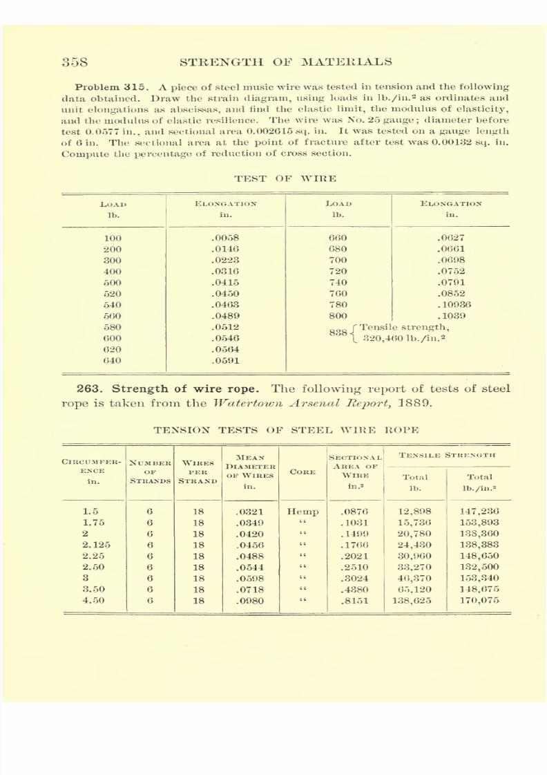
7/30/2019 Textbook on Streng 00 Slo Crich
http://slidepdf.com/reader/full/textbook-on-streng-00-slo-crich 408/433
358 STEENGTH OF MATERIALS
Problem 315. A piece of steel music wire was tested in tension and the following
data obtained. Draw the strain diagram, using loads in lb./in.2 as ordinates and
unit elongations as abscissas, and find the elastic limit, the modulus of elasticity,
and the modulus of elastic resilience. The wire was No. 25 gauge ;diameter before
test 0.0577 in., and sectional area 0. 002615 sq. in. It was tested on a gauge length
of 6 in. The sectional area at the point of fracture after test was 0.00132 sq. in.
Compute the percentage of reduction of cross section.
TEST OF WIRE
LOAD
Ib.
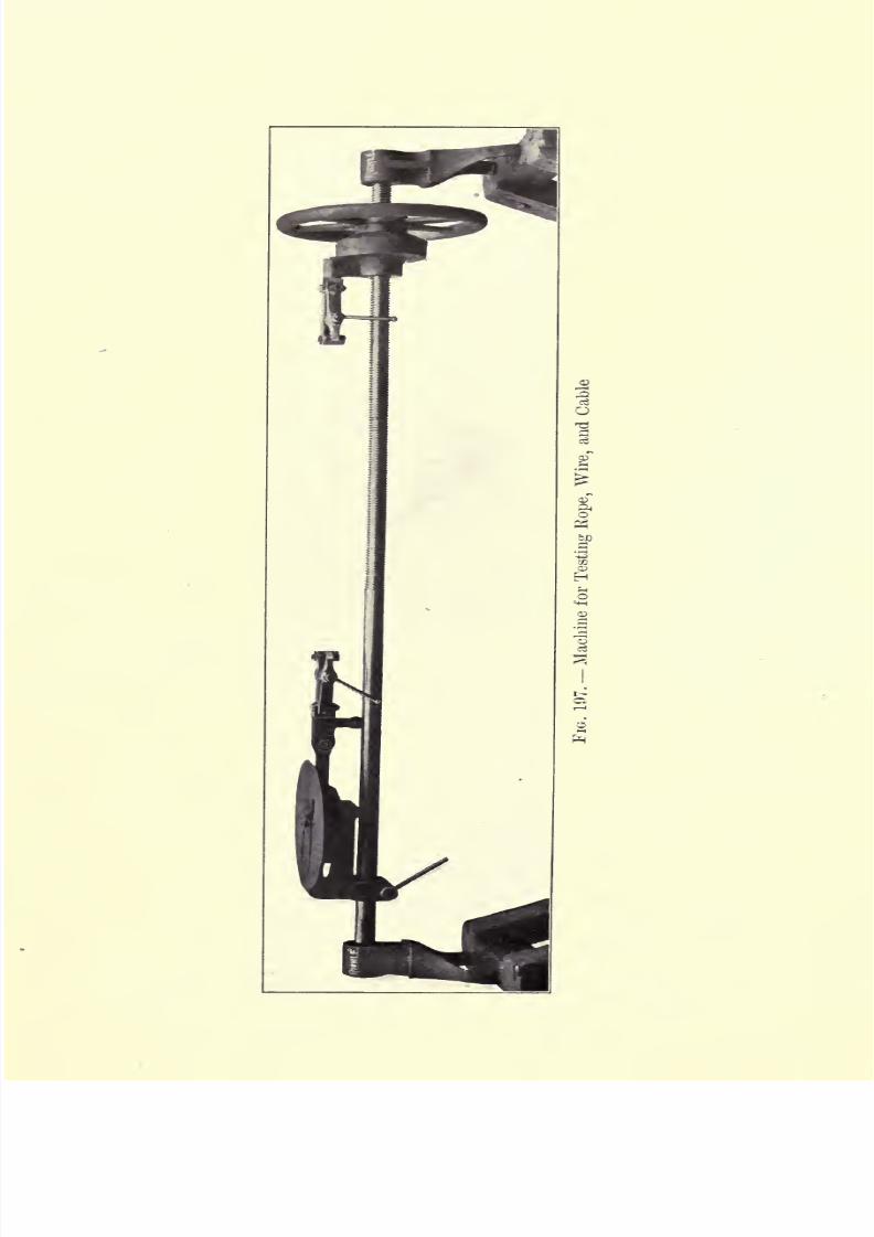
7/30/2019 Textbook on Streng 00 Slo Crich
http://slidepdf.com/reader/full/textbook-on-streng-00-slo-crich 409/433
7/30/2019 Textbook on Streng 00 Slo Crich
http://slidepdf.com/reader/full/textbook-on-streng-00-slo-crich 410/433
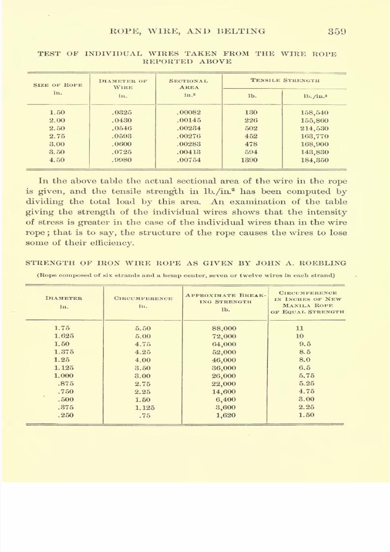
7/30/2019 Textbook on Streng 00 Slo Crich
http://slidepdf.com/reader/full/textbook-on-streng-00-slo-crich 411/433
ROPE, WIRE, AND BELTING 359
TEST OF INDIVIDUAL WIRES TAKEN FROM THE WIRE ROPEREPORTED ABOVE
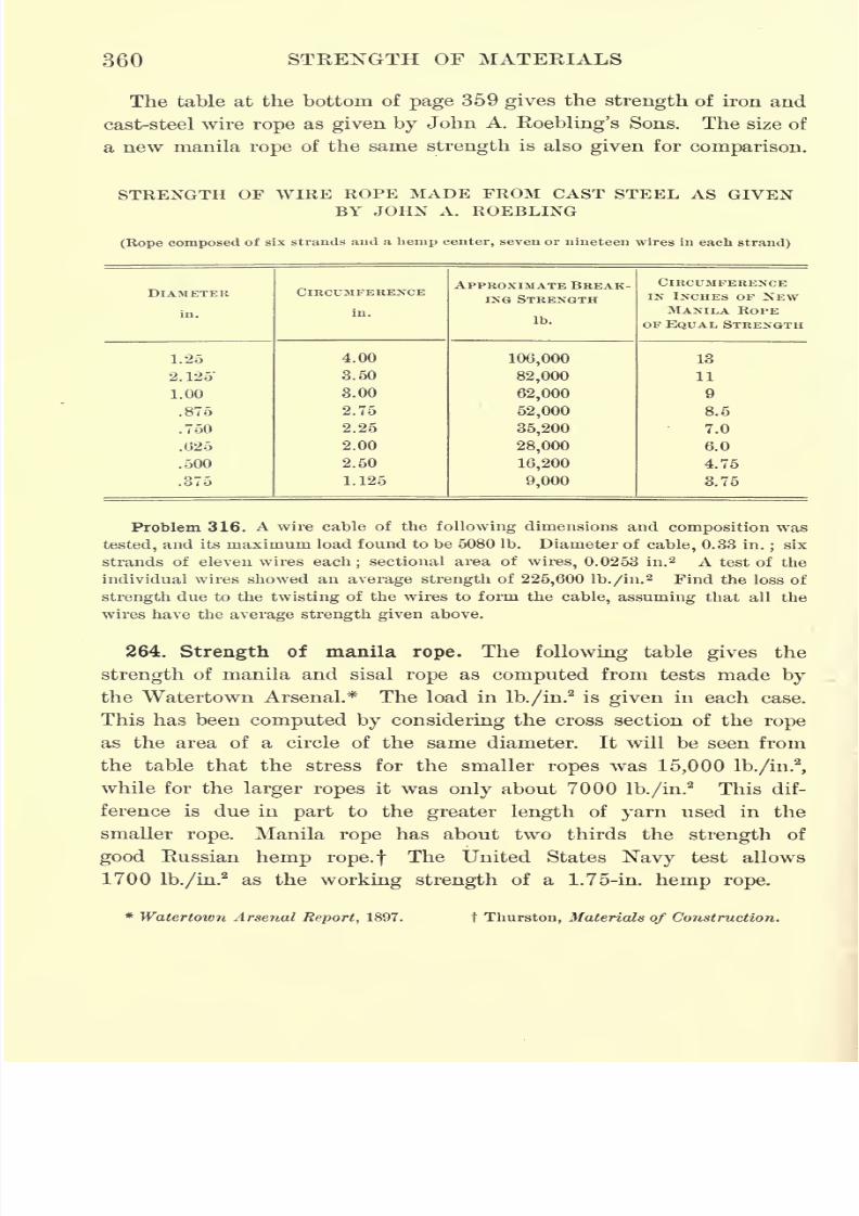
7/30/2019 Textbook on Streng 00 Slo Crich
http://slidepdf.com/reader/full/textbook-on-streng-00-slo-crich 412/433
360 STRENGTH OF MATERIALS
The table at the bottom of page 359 gives the strength of iron and
cast-steel wire rope as given by John A. Roebling's Sons. The size of
a new manila rope of the same strength is also given for comparison.
STRENGTH OF WIRE ROPE MADE FROM CAST STEEL AS GIVENBY JOHN A. ROEBLING
(Rope composed of six strands and a hemp center, seven or nineteen wires in each strand)
DIAMETER
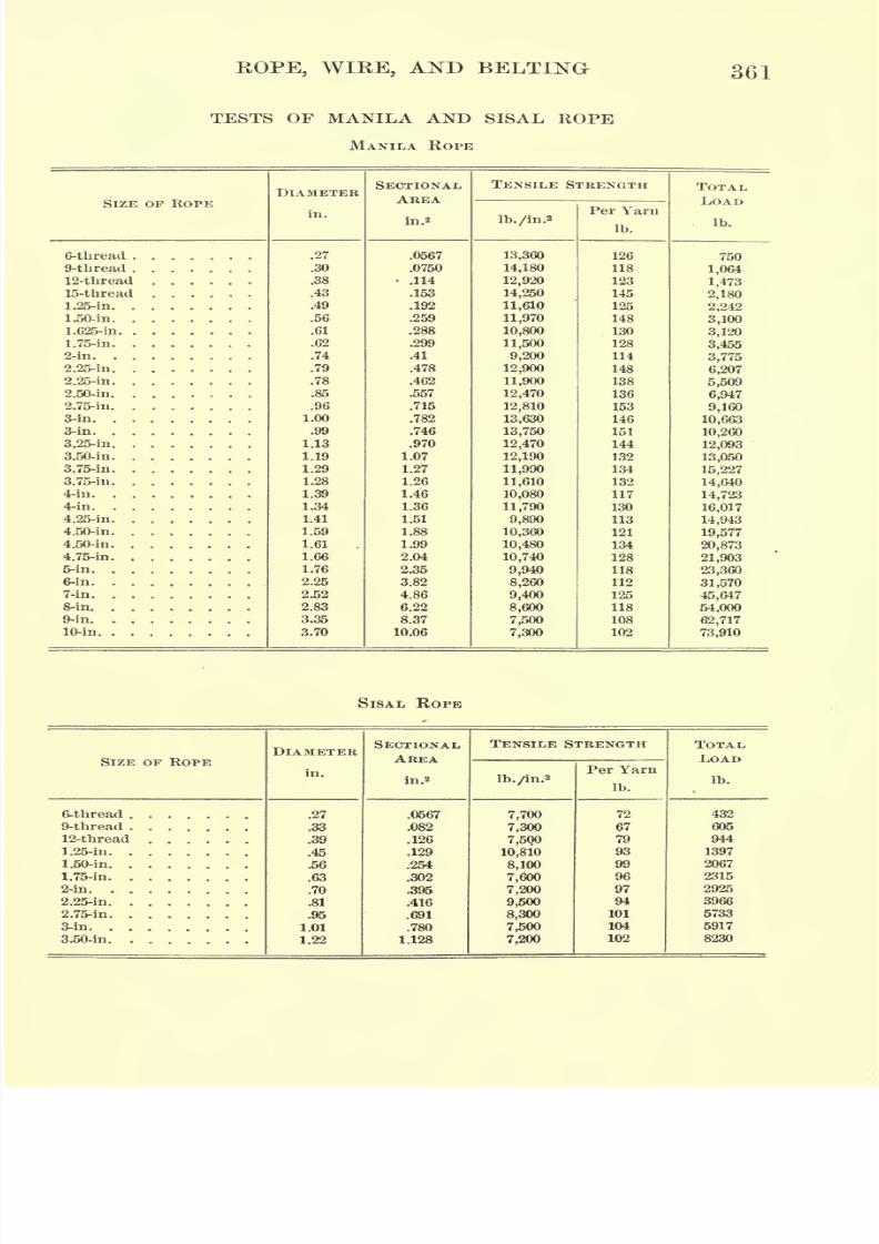
7/30/2019 Textbook on Streng 00 Slo Crich
http://slidepdf.com/reader/full/textbook-on-streng-00-slo-crich 413/433
ROPE, WIRE, AND BELTING 361
TESTS OF MANILA AND SISAL ROPE
MANILA ROPE
SIZE OF ROPE
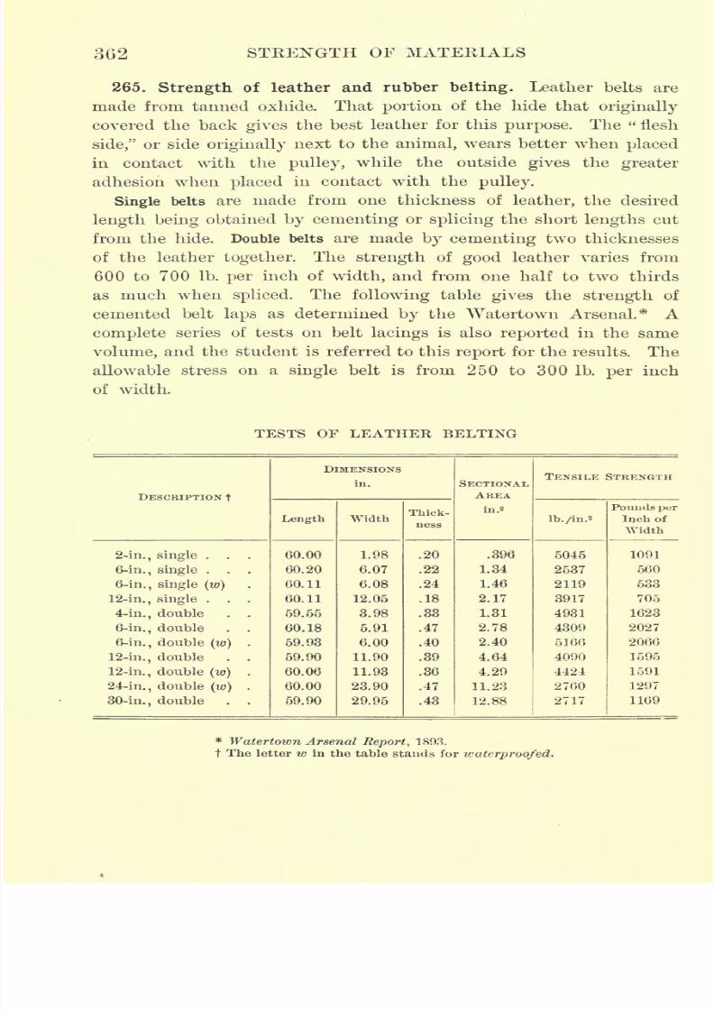
7/30/2019 Textbook on Streng 00 Slo Crich
http://slidepdf.com/reader/full/textbook-on-streng-00-slo-crich 414/433
362 STRENGTH OF MATERIALS
265. Strength of leather and rubber belting. Leather belts are
made from tanned oxhide. That portion of the hide that originally
covered theback gives
the best leather for thispurpose.
The "flesh
side," or side originally next to the animal, wears better when placed
in contact with the pulley, while the outside gives the greater
adhesion when placed in contact with the pulley.
Single belts are made from one thickness of leather, the desired
length being obtained by cementing or splicing the short lengths cut
from the hide. Double belts are made by cementing two thicknesses
of the leathertogether.
Thestrength
of
goodleather varies from
600 to 700 Ib. per inch of width, and from one half to two thirds
as much when spliced. The following table gives the strength of
cemented belt laps as determined by the Watertown Arsenal.* A
complete series of tests on belt lacings is also reported in the same
volume, and the student is referred to this report for the results. The
allowable stress on a single belt is from 250 to 300 Ib. per inch
of width.
TESTS OF LEATHER BELTING
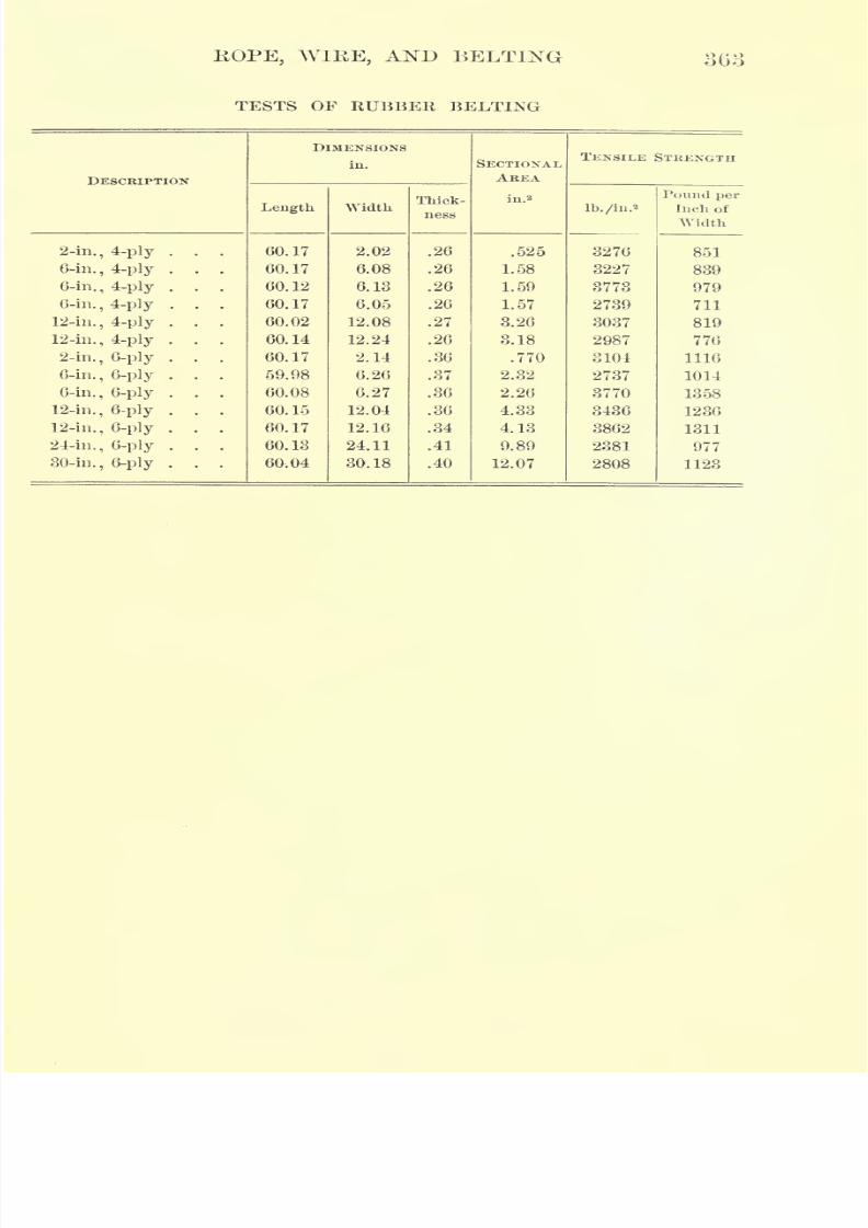
7/30/2019 Textbook on Streng 00 Slo Crich
http://slidepdf.com/reader/full/textbook-on-streng-00-slo-crich 415/433
HOPE, WIKE, AND BELTING 363
TESTS OF RUBBER BELTING
7/30/2019 Textbook on Streng 00 Slo Crich
http://slidepdf.com/reader/full/textbook-on-streng-00-slo-crich 416/433
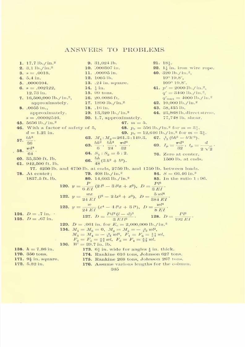
7/30/2019 Textbook on Streng 00 Slo Crich
http://slidepdf.com/reader/full/textbook-on-streng-00-slo-crich 417/433
ANSWERS TO PROBLEMS
1.
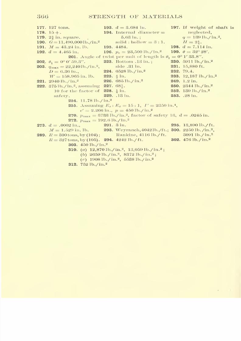
7/30/2019 Textbook on Streng 00 Slo Crich
http://slidepdf.com/reader/full/textbook-on-streng-00-slo-crich 418/433
366 STRENGTH OF MATERIALS
177. 127 tons.
178. 15 + .
179. 2f in. square.
190. =11,490,000lb./in.
5
191. M = 43.24 in. Ib.
192. d = 4.465 in.
193. d = 3.684 in.
194. Internal diameter =
5.63 in.;
solid : hollow = 3:1.
195. 4484.
196. pe= 23,500 Ib. /in.
2
197. If weight of shaft is
neglected,
q = 131) Ib./ in.2
,
II =2f198. d = 7.114 in.
199. = 32 28'.
201. Angle of twist per unit of length is 6l= V 33.8".
203. gmax = 22,2401b./in.2
,
D = 6.36 in.,
W =158.965 in. Ib.
2940 Ib./ in.'2
375 lb./in.2
, assuming
10 for the factor of
safety.
221.
230. 591 lib./ in.2
231. 15,880ft.
232. 79.4.
233. 12,187 lb./in.2
249. 1.2 in.
250. 2344 lb./in.2
252. 139 lb./in.2
253. .28 in.
223. Bottom .13 in.;
side .31 in.
224. 65281b./in.2
225. fin.
226. 685 lb./in.2
227. 68|.
228. lin.
229. .13 in.
254. 11. 78 lb./in.2
255. Assuming E8 : Ec = 15 : 1, /' = 2350 in.4
,
t' = 2.266 in., p = 450 lb./in.2
270. pmax = 3733 lb./in.2
,factor of safety 13, d = .0245 in.
272. Pmn = 192.6 lb./in.2
273. d= .0002in., 291. 3 in.
3f = 1.529 in. Ib. 293. Weyrauch,40421b./ft.
289. E = 300 tons, by (104); Rankine, 4116 Ib./ft.
# = 32 7 tons, by (105). 294. 4242 Ib./ ft.
303. 450 lb./in.2
310.(a) 12,870 lb./in.
2, 13,059 lb./in.
2;
(6)2659 lb./in.
2,8372 lb./in.
2;
(c) 1908 lb./in.2
,5538 lb./in.
2
312. 752 lb./in.2
295. 13,890 Ib./ ft.
300. 2250 lb./in.2
,
3091 lb./in.2
302. 476 lb./in.2
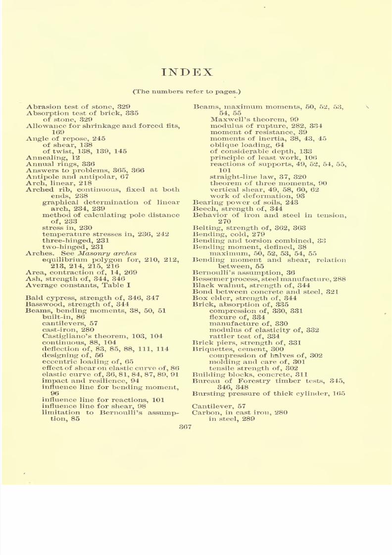
7/30/2019 Textbook on Streng 00 Slo Crich
http://slidepdf.com/reader/full/textbook-on-streng-00-slo-crich 419/433
INDEX(The numbers refer to pages.)
Abrasion test of stone, 329
Absorption test of brick, 335
of stone, 329
Allowance for shrinkage and forced fits,
169
Angle of repose, 245
of shear, 138of twist, 138, 139, 145
Annealing, 12
Annual rings, 336
Answers to problems, 365, 366
Antipole and antipolar, 67
Arch, linear, 218
Arched rib, continuous, fixed at both
ends, 238
graphical determination of linear
arch, 234, 239
method of calculating pole distanceof, 233
stress in, 230
temperature stresses in, 236, 242
three-hinged, 231
two-hinged, 231
Arches. See Masonry arches
equilibrium polygon for, 210, 212,
213, 214, 215, 216
Area, contraction of, 14, 269
Ash, strength of, 344, 346
Average constants, Table I
Bald cypress, strength of, 346, 347
Basswood, strength of, 344
Beams, bending moments, 38, 50, 51
built-in, 86
cantilevers, 57
cast-iron, 280
Castigliano's theorem, 103, 104
continuous, 88, 104
deflection of, 83, 85, 88, 111, 114
designing of, 56
eccentric loading of, 65effect of shear on elastic curve of, 86
elastic curve of, 36, 81, 84, 87, 89, 91
impact and resilience, 94
influence line for bending moment,96
influence line for reactions, 101
influence line for shear, 98
limitation to Bernoulli's assump-
tion, 85
Beams, maximum moments, 50, 52, 53,
54,55Maxwell's theorem, 99
modulus of rupture, 282, 334
moment of resistance, 39
moments of inertia, 38, 43, 45
oblique loading, 64of considerable depth, 133
principle of least work, 106
reactions of supports, 49, 52, 54, 55,
101
straight-line law, 37, 320
theorem of three moments, 90
vertical shear, 49, 58, 60, 62
work of deformation, 93
Bearing power of soils, 243
Beech, strength of, 344
Behavior of iron and steel in tension,270
Belting, strength of, 362, 363
Bending, cold, 279
Bending and torsion combined, 33
Bending moment, defined, 38
maximum, 50, 52, 53, 54, 55
Bending moment and shear, relation
between, 55
Bernoulli's assumption, 36
Bessemerprocess, steel manufacture, 288
Black walnut, strength of, 344
Bond between concrete and steel, 321
Box elder, strength of, 344
Brick, absorption of, 335
compression of, 330, 331
flexure of, 334
manufacture of, 330
modulus of elasticity of, 332
rattler test of, 334
Brick piers, strength of, 331
Briquettes, cement, 300
compression of halves of, 302
molding and care of, 301tensile strength of, 302
Building blocks, concrete, 311
Bureau of Forestry timber tests, 345,
346, 348
Bursting pressure of thick cylinder, 165
Cantilever, 57
Carbon, in cast iron, 280
in steel, 289
367
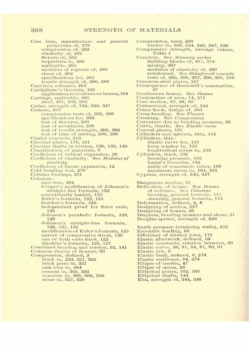
7/30/2019 Textbook on Streng 00 Slo Crich
http://slidepdf.com/reader/full/textbook-on-streng-00-slo-crich 420/433
368 STRENGTH OF MATERIALS
Cast iron, manufacture and general
properties of, 279
compression of, 282
elasticity of, 282
flexureof,
282
impurities in, 280
malleable, 285
modulus of rupture of, 286
shear of, 282
specifications for, 285
tensile strength of, 280, 286
Cast-iron columns, 284
Castigliano's theorem, 103
application to continuous beams, 104
Castings, malleable, 285
steel, 291, 292, 293
Cedar, strength of, 344, 346, 347
Cement, 297
compression tests of, 302, 303
specifications for, 303
test of fineness, 299
test of soundness, 298
test of tensile strength, 300, 302
test of time of setting, 299, 300
Cinder concrete, 310
Circular plates, 179, 181
Circular shafts in torsion, 138, 139, 140
Classification of materials, 9Coefficient of cubical expansion, 29
Coefficient of elasticity. See Modulus of
elasticity
Coefficient of linear expansion, 12
Cold bending test, 279
Column footings, 251
Columns :
cast-iron, 284
Cooper's modification of Johnson's
straight-line formula, 132
eccentrically loaded, 133
Euler's formula, 122, 123
Gordon's formula, 126
independent proof for fixed ends,123
Johnson's parabolic formula, 128,
129
Johnson's straight-line formula,
130, 131, 132
modification of Euler's formula, 125
nature of compressive stress, 120
one or both ends fixed, 122
Rankine's formula, 126, 127Combined bending and torsion, 33, 141
Common theory of flexure,~3~6
Compression, defined, 2
brick in, 330, 331, 332
brick piers in, 331
cast iron in, 284
cement in, 302, 303
concrete in, 308, 309, 310
stone in, 327, 328
Compression, tests, 269
timber in, 338, 344, 346, 347, 350
Compressive strength, average values,Table I
Concrete. SeeMasonry
arches
building blocks of, 311, 312
mixing, 307
modulus of elasticity of, 309
reenforced. See Reenforced concrete
tests of, 305, 306, 307, 308, 309, 310
Concrete-steel plates, 187
Consequence of Bernoulli's assumption,37
Continuous beams. See BeamsContraction of area, 14, 271
Core section, 67, 68, 69
Cottonwood, strength of, 344Crane hook, design of, 205
Cross-bending. See Flexure
Crushing. See CompressionCurvature due to bending moment, 36
Curve, elastic. See Elastic curve
Curved pieces, 191
Cylinders and spheres, thin, 154
Cylinders, thin :
elastic curve for, 157
hoop tension in, 155
longitudinal stress in, 155Cylinders, thick, 162
bursting pressure, 165
Lamp's formulas, 162
made of concentric tubes, 166
maximum stress in, 164, 165
Cypress, strength of, 346, 347
Dangerous section, 51
Deflection, of beams. See Beams
of columns. See Columns
bending, general formula, 111
shearing, general formula, 114
Deformation, defined, 2, 4
Designing of arches, 227
Designing of beams, 56
Diagram, bending moment and shear, 51
Douglas spruce, strength of, 346
Earth pressure (retaining walls), 253
Eccentric loading, 65
Efficiency of riveted joint, 172
Elastic afterwork, defined, 10
Elastic constants, relation between, 30Elastic curve, 36, 81, 84, 87, 89, 91
Elastic law, 8
Elastic limit, defined, 6, 274
Elastic resilience, 94, 274
Ellipse of inertia, 47
Ellipse of stress, 26
Elliptical plates, 182, 183
Elliptical shafts, 144
Elm, strength of, 344, 346
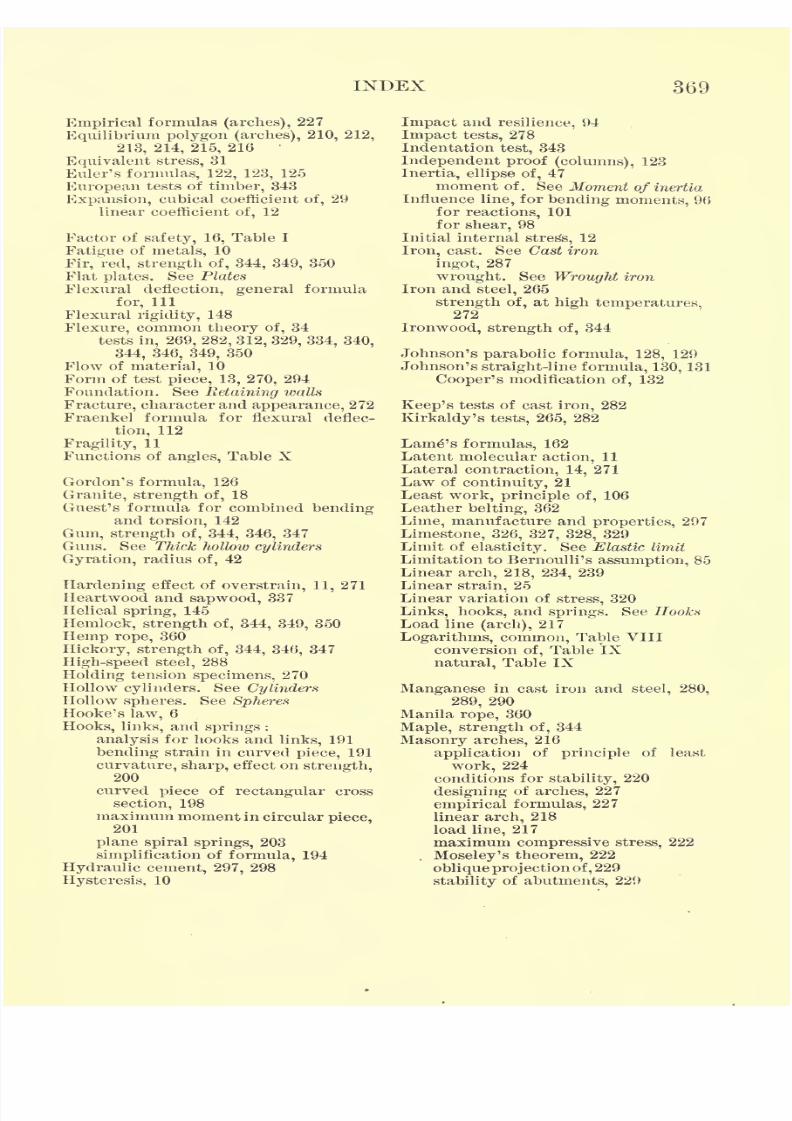
7/30/2019 Textbook on Streng 00 Slo Crich
http://slidepdf.com/reader/full/textbook-on-streng-00-slo-crich 421/433
INDEX 369
Empirical formulas (arches), 227
Equilibrium polygon (arches), 210, 212,
213, 214, 215, 216
Equivalent stress, 31
Euler's formulas, 122, 123, 125
European tests of timber, 343
Expansion, cubical coefficient of, 29
linear coefficient of, 12
Factor of safety, 16, Table I
Fatigue of metals, 10
Fir, red, strength of, 344, 349, 350
Flat plates. See Plates
Flexural deflection, general formula
for, 111
Flexural rigidity, 148Flexure, common theory of, 34
tests in, 269, 282, 312, 329, 334, 340,
344, 346, 349, 350
Flow of material, 10
Form of test piece, 13, 270, 294
Foundation. See Retaining walls
Fracture, character and appearance, 272
Fraenkel formula for flexural deflec-
tion, 112
Fragility, 11
Functions of angles, Table X
Gordon's formula, 126
Granite, strength of, 18
Guest's formula for combined bendingand torsion, 142
Gum, strength of, 344, 346, 347
Guns. See Thick hollow cylinders
Gyration, radius of, 42
Hardening effect of overstrain, 11, 271
Heartwood and sapwood, 337
Helical spring, 145Hemlock, strength of, 344, 349, 350
Hemp rope, 360
Hickory, strength of, 344, 346, 347
High-speed steel, 288
Holding tension specimens, 270
Hollow cylinders. See CylindersHollow spheres. See SpheresHooke's law, 6
Hooks, links, and springs :
analysis for hooks and links, 191
bendingstrain in curved
piece,191
curvature, sharp, effect on strength,200
curved piece of rectangular cross
section, 198
maximum moment in circular piece,
201
plane spiral springs, 203
simplification of formula, 194
Hydraulic cement, 297, 298
Hysteresis, 10
Impact and resilience, 94
Impact tests, 278
Indentation test, 343
Independent proof (columns), 123
Inertia, ellipse of, 47moment of. See Moment of inertia
Influence line, for bending moments, 96
for reactions, 101
for shear, 98
Initial internal stress, 12
Iron, cast. See Cast iron
ingot, 287
wrought. See Wrought iron
Iron and steel, 265
strength of, at high temperatures,
272Ironwood, strength of, 344
Johnson's parabolic formula, 128, 129
Johnson's straight-line formula, 130, 131
Cooper's modification of, 132
Keep's tests of cast iron, 282
Kirkaldy's tests, 265, 282
Lamp's formulas, 162
Latent molecular action, 11
Lateral contraction, 14, 271
Law of continuity, 21
Least work, principle of, 106
Leather belting, 362
Lime, manufacture and properties, 297
Limestone, 326, 327, 328, 329
Limit of elasticity. See Elastic limit
Limitation to Bernoulli's assumption, 85
Linear arch, 218, 234, 239
Linear strain, 25
Linear variation of stress, 320
Links, hooks, and springs. See HooksLoad line (arch), 217
Logarithms, common, Table VIII
conversion of, Table IX
natural, Table IX
Manganese in cast iron and steel, 280,
289, 290
Manila rope, 360
Maple, strength of, 344
Masonry arches, 216
applicationof
principleof least
work, 224
conditions for stability, 220
designing of arches, 227
empirical formulas, 227
linear arch, 218
load line, 217
maximum compressive stress, 222
Moseley's theorem, 222
obliqueproj ection of, 229
stability of abutments, 229
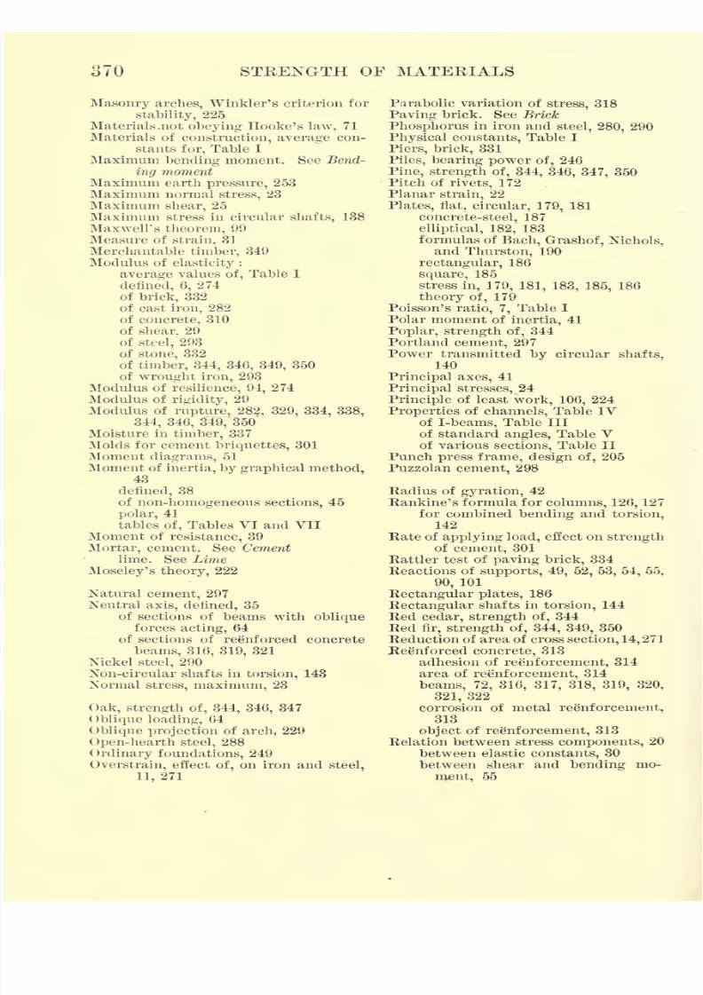
7/30/2019 Textbook on Streng 00 Slo Crich
http://slidepdf.com/reader/full/textbook-on-streng-00-slo-crich 422/433
370 STRENGTH OF MATERIALS
Masonry arches, Winkler's criterion for
stability, 225
Materials .not obeying Hooke's law, 71
Materials of construction, average con-
stants for, Table I
Maximum bending moment. See Bend-ing moment
Maximum earth pressure, 253
Maximum normal stress, 23
Maximum shear, 25
Maximum stress in circular shafts, 138
Maxwell's theorem, 99
Measure of strain, 31
Merchantable timber, 349
Modulus of elasticity :
average values of, Table I
denned, 6,
274
of brick, 332
of cast iron, 282
of concrete, 310
of shear, 29
of steel, 293
of stone, 332
of timber, 344, 346, 349, 350
of wrought iron, 293
Modulus of resilience, 94, 274
Modulus of rigidity, 29
Modulus of rupture, 282, 329, 334, 338,
344, 346, 349, 350Moisture in timber, 337
Molds for cement briquettes, 301
Moment diagrams, 51
Moment of inertia, by graphical method,43
defined, 38
of non-homogeneous sections, 45
polar, 41
tables of, Tables VI and VIIMoment of resistance, 39
Mortar, cement. See Cementlime. See Lime
Moseley's theory, 222
Natural cement, 297
Neutral axis, defined, 35
of sections of beams with obliqueforces acting, 64
of sections of reenforced concrete
beams, 316, 319, 321
Nickel steel, 290
Non-circular shafts in torsion, 143
Normal stress, maximum, 23
Oak, strength of, 344, 346, 347
Oblique loading, 64
Oblique projection of arch, 229
Open-hearth steel, 288
Ordinary foundations, 249
Overstrain, effect of, on iron and steel,
11, 271
Parabolic variation of stress, 318
Paving brick. See Brick
Phosphorus in iron and steel, 280, 290
Physical constants, Table I
Piers, brick, 331
Piles, bearing power of, 246Pine, strength of, 344, 346, 347, 350
Pitch of rivets, 172
Planar strain, 22
Plates, flat, circular, 179, 181
concrete-steel, 187
elliptical, 182, 183
formulas of Bach, Grashof, Nichols,
and Thurston, 190
rectangular, 186
square, 185
stressin, 179, 181, 183, 185,
186
theory of, 179
Poisson's ratio, 7, Table I
Polar moment of inertia, 41
Poplar, strength of, 344
Portland cement, 297
Power transmitted by circular shafts,
140
Principal axes, 41
Principal stresses, 24
Principle of least work, 106, 224
Properties of channels, Table IV
of I-beams, Table III
of standard angles, Table Vof various sections, Table II
Punch press frame, design of, 205
Puzzolan cement, 298
Eadius of gyration, 42
Rankine's formula for columns, 126, 127
for combined bending and torsion,
142
Rate of applying load, effect on strength
of cement, 301Rattler test of paving brick, 334
Reactions of supports, 49, 52, 53, 54, 55,
90, 101
Rectangular plates, 186
Rectangular shafts in torsion, 144
Red cedar, strength of, 344
Redfir, strength of, 344, 349, 350
Reduction of area of cross section, 14, 271
Reenforced concrete, 313
adhesion of reenforcement, 314
area of reenforcement, 314
beams, 72, 316, 317, 318, 319, 320,
321, 322
corrosion of metal reenforcement,313
object of reenforcement, 313
Relation between stress components, 20
between elastic constants, 30
between shear and bending mo-
ment, 55
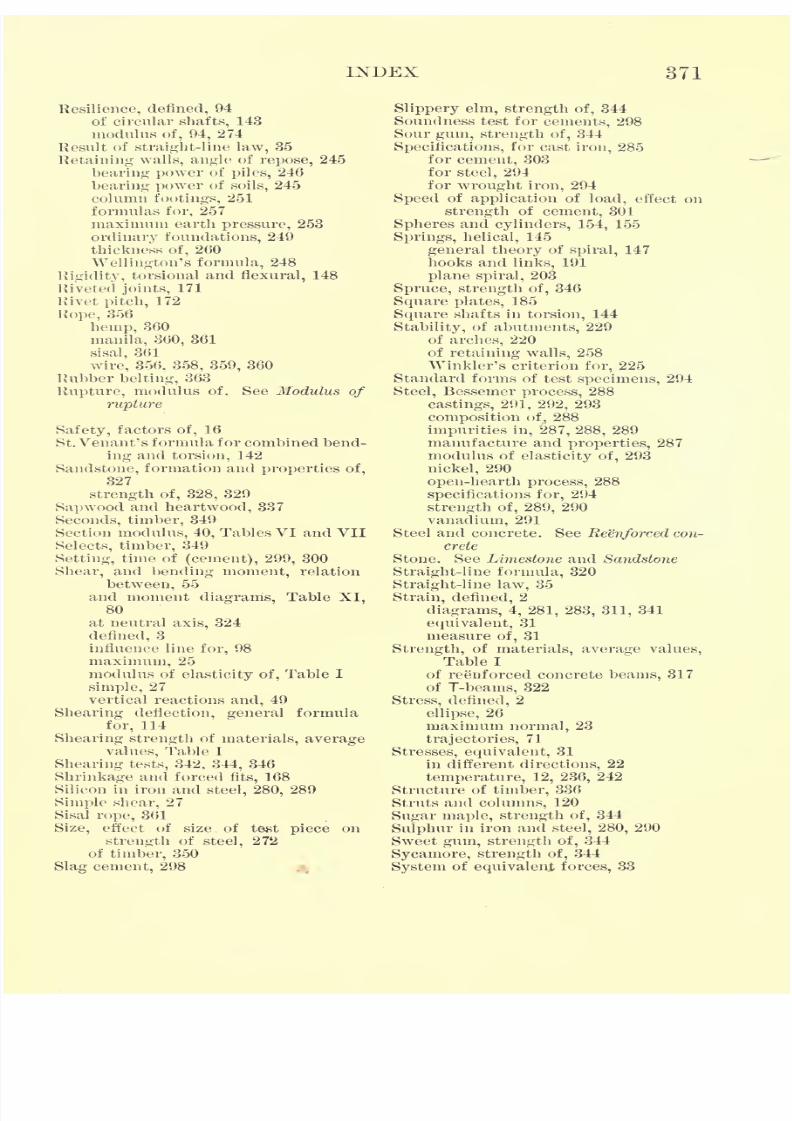
7/30/2019 Textbook on Streng 00 Slo Crich
http://slidepdf.com/reader/full/textbook-on-streng-00-slo-crich 423/433
INDEX 371
Resilience, defined, 94
of circular shafts, 143
modulus of, 94, 274
Result of straight-line law, 35
Retaining walls, angle of repose, 245bearing power of piles, 246
bearing power of soils, 245
column footings, 251
formulas for, 257
maximum earth pressure, 253
ordinary foundations, 249
thickness of, 260
Wellington's formula, 248
Rigidity, torsional and flexural, 148
Riveted joints, 171
Rivetpitch,
172
Rope, 356
hemp, 360
manila, 360, 361
sisal, 361
wire, 356, 358, 359, 360
Rubber belting, 363
Rupture, modulus of. See Modulus of
rupture
Safety, factors of, 16
St. Venant's formula for combined bend-
ing and torsion, 142
Sandstone, formation and properties of,
327
strength of, 328, 329
Sapwood and heartwood, 337
Seconds, timber, 349
Section modulus, 40, Tables VI and VII
Selects, timber, 349
Setting, time of (cement), 299, 300
Shear, and bending moment, relation
between, 55
and moment diagrams, Table XI,80
at neutral axis, 324
defined, 3
influence line for, 98
maximum, 25
modulus of elasticity of, Table I
simple, 27
vertical reactions and, 49
Shearing deflection, general formula
for, 114
Shearing strength of materials, average
values, Table I
Shearing tests, 342, 344, 346
Shrinkage and forced fits, 168
Silicon in iron and steel, 280, 289
Simple shear, 27
Sisal rope, 361
Size, effect of size, of test piece on
strength of steel, 272
of timber, 350
Slag cement, 298
Slippery elm, strength of, 344
Soundness test for cements, 298
Sour gum, strength of, 344
Specifications, for cast iron, 285
for cement, 303for steel, 294
for wrought iron, 294
Speed of application of load, effect on
strength of cement, 301
Spheres and cylinders, 154, 155
Springs, helical, 145
general theory of spiral, 147
hooks and links, 191
plane spiral, 203
Spruce, strength of, 346
Square plates,185
Square shafts in torsion, 144
Stability, of abutments, 229
of arches, 220
of retaining walls, 258
Winkler's criterion for, 225
Standard forms of test specimens, 294
Steel, Bessemer process, 288
castings, 291, 292, 293
composition of, 288
impurities in, 287, 288, 289
manufacture and properties, 287
modulus of elasticity of, 293
nickel, 290
open-hearth process, 288
specifications for, 294
strength of, 289, 290
vanadium, 291
Steel and concrete. See Reenforced con-
crete
Stone. See Limestone and Sandstone
Straight-line formula, 320
Straight-line law, 35
Strain, defined, 2diagrams, 4, 281, 283, 311, 341
equivalent, 31
measure of, 31
Strength, of materials, average values,
Table I
of reenforced concrete beams, 317
of T-beams, 322
Stress, defined, 2
ellipse, 26
maximum normal, 23
trajectories, 71
Stresses, equivalent, 31
in different directions, 22
temperature, 12, 236, 242
Structure of timber, 336
Struts and columns, 120
Sugar maple, strength of, 344
Sulphur in iron and steel, 280, 290
Sweet gum, strength of, 344
Sycamore, strength of, 344
System of equivalent forces, 33

7/30/2019 Textbook on Streng 00 Slo Crich
http://slidepdf.com/reader/full/textbook-on-streng-00-slo-crich 424/433
372 STRENGTH OF MATERIALS
Tamarack, strength of, 344
Temperature, effect on strength of steel,
272
effect of, on strength of concrete, 312
Temperature stresses, 12, 236,242
Tensile strength, average values, 18
Tensile tests, 266
of belting, 362, 363
of cast iron, 280, 286
of cement, 301, 302
of rope, 361
of steel, 289, 290, 292
of timber, 343
of wire rope, 358, 359, 360
of wrought iron, 294
Tension, denned, 2
Tenth census timber tests, 344Test pieces, large and small, 272, 350
Test specimens, standard forms of,
294
Theorem of three moments, 90
Theorems on moment of inertia, 40
Theory of flat plates, 179
Theory of flexure, common, 36
Thick hollow cylinders. See Cylinders
Thickness of retaining walls, 260
Thin hollow cylinders. See Cylinders
Timber, absorption process, 352annual rings, 336
full-cell creosoting process, 352
moisture in, 337
results of tests, 344, 346, 347, 349,
350
Riiping process, 353
sapwood and heartwood, 337
strength of, 337
strength of treated, 353
structure of, 336
tests of treated ties, 354
treated, 351
zinc chloride process, 352
Time effect, 9
Tool steel, 287
Torsion, and bending combined, 32, 141
angle of twist, 139, 145, 274
Torsion, as test for shear, 277
circular shafts in, 138, 139, 140
elliptical shafts in, 144
maximum stress in circular shafts
in,
138
non-circular shafts in, 143
rectangular and square shafts in,
144
resilience of circular shafts in, 143
test specimen, 276
tests, 275
triangular shafts in, 145
Torsional rigidity, 148
Transverse tests. See Flexure
Tubes, collapse of, under external
pressure, 159
practical formulas for collapse of,
166
Ultimate strength, defined, 6, 7
average values for, Table I
Unit deformation, 4
Unit stress, denned, 3
United States Forest Service, 348
Vanadium steel, 291
Vertical reaction and shear, 49
Wellington's formula, 248
Winkler's criterion for stability, 225
Wire, 356
Wire rope. See RopeWood. See Timber
Work, defined. See Resilience
of deformation of beams, 93
Working stress in concrete beams, 322
Wrought iron, impurities in, 290
manufacture and properties, 286,
290
modulus of elasticity of, 293
specifications for, 294
Yield point, defined, 6, 270
Young's modulus, 6
average values for, Table I

7/30/2019 Textbook on Streng 00 Slo Crich
http://slidepdf.com/reader/full/textbook-on-streng-00-slo-crich 425/433
ANNOUNCEMENTS
7/30/2019 Textbook on Streng 00 Slo Crich
http://slidepdf.com/reader/full/textbook-on-streng-00-slo-crich 426/433
7/30/2019 Textbook on Streng 00 Slo Crich
http://slidepdf.com/reader/full/textbook-on-streng-00-slo-crich 427/433
BOOKS ON THE HISTORY OFMATHEMATICS
KARA ARITHMETICABy DAVID EUGENE SMITH, Professor of Mathematics in Teachers College, Columbia
University. 8vo, cloth, 500 pages, illustrated, $4.50
A CATALOGUE of arithmetics printed before 1601, with a descrip-tion of the early textbooks and works bearing upon arithmetic, nowin Mr. George A. Plimpton's library, numbering three hundred and
seventy-four, besides some sixty-eight manuscripts. Among this num-
ber are included most of the important arithmetics of the formative
period in the modern history of the subject. Not only from the bibli-
ographical but also from the historical standpoint, this is a neces-
sary book of reference for all bibliophiles, librarians, and teachers of
secondary mathematics.
Such a volume as this is rarer than rare arithmetics. An admirable
piece of bookwork. The Independent, New York City.
Not only is this publication of interest to teachers and lovers of old
books, but it contains material which will be of marked service to the
historian. The Nation, New York City.
HINDU-ARABIC NUMERALSBy DAVID EUGENE SMITH, Professor of Mathematics in Teachers College, Columbia
University, and Louis C. KARPINSKI, Instructor in Mathematics in the Uni-
versity of Michigan, Ann Arbor. 8vo, cloth, 160 pages, $1.25
ALTHOUGH it has long been known that the numerals ordinarily em-
ployed in business, and commonly attributed to the Arabs, are not ofArabic origin, and although numerous monographs have been written
concerning their derivation, no single work has yet appeared in which
the complete story of their rise and development has been told. In the
preparation of this treatise the authors have examined every importantbook and monograph that has appeared upon the
subject, consulting
the principal libraries of Europe as well as America, examining manymanuscripts, and sifting the evidence with greatest care. The result is
a scholarly discussion of the entire question of the origin of the numer-
als, the introduction of the zero, the influence of the Arabs, and the
spread of the system about the shores of the Mediterranean and into
the various countries of Europe.
uga
GINN AND COMPANY PUBLISHERS
7/30/2019 Textbook on Streng 00 Slo Crich
http://slidepdf.com/reader/full/textbook-on-streng-00-slo-crich 428/433
ADVANCED CALCULUSBy EDWIN BIDWELL WILSON, Professor of Mathematics in the
Massachusetts Institute of Technology
8vo, cloth, 280 pages, $2.75
PROFESSOR WILSON'S" Advanced Calculus
"supplies in a single
volume a comprehensive second course in calculus. Although mod-
ern rigorous tendencies are given due attention, the chief aim of the
book is to confirm and to extend the student's knowledge of the great
formal methods of analysis that are essential alike to the practical
and to the pure mathematician. To connect with elementary texts,
two chapters in review are supplied, and many subsequent chapters
are tempered with material which is essentially review. Advanced
differential calculus is represented by work on Taylor's Formula, with
special reference to approximate analysis, partial differentiation of
explicit and of implicit functions, complex numbers, and vectors.
INTRODUCTORY REVIEW
Chapter I Review of Fundamental Rules
" II Review of Fundamental Theory
PART I. DIFFERENTIAL CALCULUS
" III Taylor's Formula and Allied Topics" IV Partial Differentiation
; Explicit Functions
" V Partial Differentiation; Implicit Functions
" VI Complex Numbers and Vectors
PART II. DIFFERENTIAL EQUATIONS
" VII General Introduction to Differential Equations" VIII The Commoner Ordinary Differential Equations" IX Additional Types of Ordinary Equations" X Differential Equations in more than Two Variables
GINN AND COMPANY PUBLISHERS
7/30/2019 Textbook on Streng 00 Slo Crich
http://slidepdf.com/reader/full/textbook-on-streng-00-slo-crich 429/433
APPLICATIONS OF THE CALCULUS TO MECHANICSBy E. R. HEDRICK, Professor of Mathematics in the University of Missouri,
~nd O. D. KELLOGG, Assistant Professor of Mathematics
in the University of Missouri
8vo, cloth, 116 pages, with diagrams, $1.25
THISbook presents a completed summary of those parts
of mechanics which occur as applications of the calculus.
Although intended primarily as a supplement to the usual
standard course in calculus, it may be used independently as a
text for a short course on the mathematical side of mechanics,
if the time allotted to the former study is not sufficient to in-
clude this work.
As a review it fastens in the student's mind the notions of
mechanics previously gained. It aims also to present these
topics in a new light, as articulated portions of one general
theory, and thus to make mechanics seem an integral subject.
As a preparation for more extended courses in mechanics, or
indeed for courses dealing with any applications of the calcu-
lus, the material presented is valuable in showing concretely
how the theoretical ideas of this subject are used in specific
practical applications.
The course outlined in the book is the result of a number of
years' experience in presenting this material to classes in the;
calculus, both at the University of Missouri and elsewhere. The\
text itself is a modification.
jfa similar text written by Pro-
|
fessor Hedrick and publisher! in mimeograph fot the use of *\
students at the Sheffield Scientific School.
GINN AND COMPANY PUBLISHERS
7/30/2019 Textbook on Streng 00 Slo Crich
http://slidepdf.com/reader/full/textbook-on-streng-00-slo-crich 430/433
A COURSE IN MATHEMATICSBy FREDERICK S. WOODS and FREDERICK H. BAILEY, Professors of
Mathematics in the Massachusetts Institute of Technology
Volume I. Algebraic Equations, Functions of One Variable, An-
alytic Geometry, Differential Calculus. 8vo. Cloth. 385 pages.
With Diagrams. $2.25
Volume II. Integral Calculus, Functions of Several Variables,
Space Geometry, DifferentialEquations. 8vo. Cloth. 410 pages.
With Diagrams. $2.25
THIScourse in mathematics is designed to present in a con-
secutive and homogeneous manner an amount of material
generally given in distinct courses under the various names of
algebra, analytic geometry, differential and integral calculus, and
differential equations. The aim is to give the student a better
grasp of mathematics as a whole and of the interdependence of
its variousparts,
and to accustom him to
use,in later
applications,the method best adapted to the problem in hand. A decided ad-
vantage is gained in the first volume by the introduction of the
principles of analytic geometry and calculus earlier than is usual.
In this way these subjects are studied longer than is otherwise
possible, thus leading to greater familiarity with their methods
and greater freedom and skill in their application.
Special features of the second volume are the early introduction
of a chapter on simple differential equations in close connection
with integration, and a chapter on line integrals.
H. E. SLAUGHT, Assistant Professor of Mathematics, The Univer-
sity of Chicago: It is directly in line with the spirit of our programmeat The University of Chicago, and we wish to register our approval of
its plan and purpose. The book is in the spirit of advance and the authors
are on the right track. We shall use it in two sections next quarter.
WILLIAM F. OSGOOD, Professor of Mathematics, Harvard Univer-
sity: It is a good, clear presentation and will be welcome to manyteachers. As regards the scholarship that characterizes the book, its
order is distinctly higher than that of most American or English books
on analyticgeometry
and calculus.
GINN AND COMPANY PUBLISHERS
7/30/2019 Textbook on Streng 00 Slo Crich
http://slidepdf.com/reader/full/textbook-on-streng-00-slo-crich 431/433
7/30/2019 Textbook on Streng 00 Slo Crich
http://slidepdf.com/reader/full/textbook-on-streng-00-slo-crich 432/433
'"aSBcwIN
woaAn
55*8*35^55=-~ _
7/30/2019 Textbook on Streng 00 Slo Crich
http://slidepdf.com/reader/full/textbook-on-streng-00-slo-crich 433/433
YC
265507
UNIVERSITY OF CALIFORNIA LIBRARY


![[Ansel C. Ugural, Saul K. Fenster] Advanced Streng(BookZa.org) (1) (1)](https://img.pdfslide.us/doc/110x75/563dba5b550346aa9aa4eca0/ansel-c-ugural-saul-k-fenster-advanced-strengbookzaorg-1-1.jpg)