Embed Size (px)
Citation preview
T130 MODELAIRPLANENEWS.COM
THE PREDECESSOR to the DC-7, The DC-6B
Mainliner was the last of the Douglas-built
piston-driven airliners. It went into service in
1947, and 362 were built. The Mainliner
remained in full service until the early ’50s
and more than 100 continued in limited ser-
vice until the 1980s. Many still fly today as
cargo haulers and fire bombers. My dad was
an aircraft mechanic with United Airlines
when the DC-6s were in service; so naturally,
I have a soft spot for the old airliner.
THE DESIGN
With its 5-foot wingspan, the DC-6 is a
relatively large park flyer. I designed it
around the GWS, IPS drive systems, so I
made the structure light yet strong enough
to support its substantial size. It is uncom-
plicated to build and uses formers and
stringers to fill out its shape.
ON THE BENCH
This model is not hard to build, but it has
many parts. To speed construction, I offer a
laser-cut parts kit that contains 271 parts;
contact me at [email protected].
WING
Pin the wing-alignment jig stick over the
plan; then make the wingtip bows using the
patterns provided. Assemble the R3 and R4
assemblies; then glue the main spar shear
webs together, but don’t join the A1 and A2
assemblies yet.
Pin the lower main spar over the plan,
and use the ribs as a guide to align and glue
the shear web to the spar; then attach ribs
R2 thru R12. Fit and glue the landing-gear
mounts, and then glue the top main spar
into place. Then add the leading and trail-
ing edges, the aileron hinge spar and the tip
CONSTRUCTIONTEXT & PHOTOS BY PAT TRITLE
DOUGLASDC-6MAINLINERThis classic multi-engine transport uses e-power and traditional building techniques
The fuselage starts with this basic framework. Rounded formers and external stringers give theDC-6 its final shape.
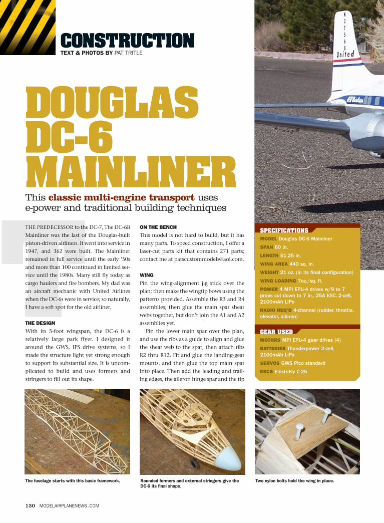
Two nylon bolts hold the wing in place.
SPECIFICATIONSMODEL Douglas DC-6 Mainliner
SPAN 60 in.
LENGTH 51.25 in.
WING AREA 440 sq. in.
WEIGHT 21 oz. (in its final configuration)
WING LOADING 7oz./sq. ft.
POWER 4 MPI EPU-4 drives w/9 to 7props cut down to 7 in., 25A ESC, 2-cell,2100mAh LiPo
RADIO REQ’D 4-channel (rudder, throttle,elevator, aileron)
GEAR USEDMOTORS MPI EPU-4 gear drives (4)
BATTERIES Thunderpower 2-cell,2100mAh LiPo
SERVOS GWS Pico standard
ESCS ElectriFly C-25
Contruct Redesign v3 2/9/09 4:18 PM Page 130
MARCH 2007 131
bow. Fit and glue the aileron spar and con-
trol horn mount into place, and then attach
all the aileron ribs.
To join the wing panels and block the tips,
fit the R1 rib onto the spar and fit the oppo-
site wing panel in place. Trim the leading
and trailing edges and spars as needed; then
glue the left and right wing panels together.
Once the glue has dried, pin the left wing
back over the plan; use the alignment jig to
hold its shape, and glue all the top stringers
into place. Repeat the process for the right
panel; then lift the wing from the board,
rods and horns, and cut the ailerons from
the wing. Sand the ailerons to shape, and
fit the hinges in place, but don’t glue
them in yet.
ENGINE NACELLES
Build four inboard and four outboard
nacelle side frames, and join the frames
together to assemble two inner and two
outer nacelle units. Build the motor
mounts, and glue them into place. Once
the glue has dried, glue the nacelle frames
to the wing. Glue formers N1, N2 and then
the balsa stingers into place.
Now is a good time to install the motors
and run the motor wiring. Test the power
system now while it is still easy to fix
any problems.
FUSELAGE FRAMING
Pin parts B1, B2 and B3 over the fuselage
frame drawing, and then glue the longerons
as well as the vertical and diagonal bracing.
After the glue has dried, remove them from
the board and build the second frame in the
same fashion. Join the sides upside-down
over the plan’s top view; then install former
and glue all the bottom stringers into place.
Fit and glue the trailing edge pieces and
sand them to shape.
Assemble the main landing gear and lash
them to their mounts with Kevlar thread
and glue. Sand the wing to final shape, and
then cut out the leading-edge sections for
the engine nacelle structures.
Fit and glue the aileron servos into the
wing, and then install the aileron control
horns (don’t glue them in yet). Make the
pushrods, and install them when every-
thing is aligned properly; then remove the
It’s best to run the power wires for the motorsbefore the wing is covered.
After the main wing structure is completed,remove the sections shown here for the enginenacelle structures.
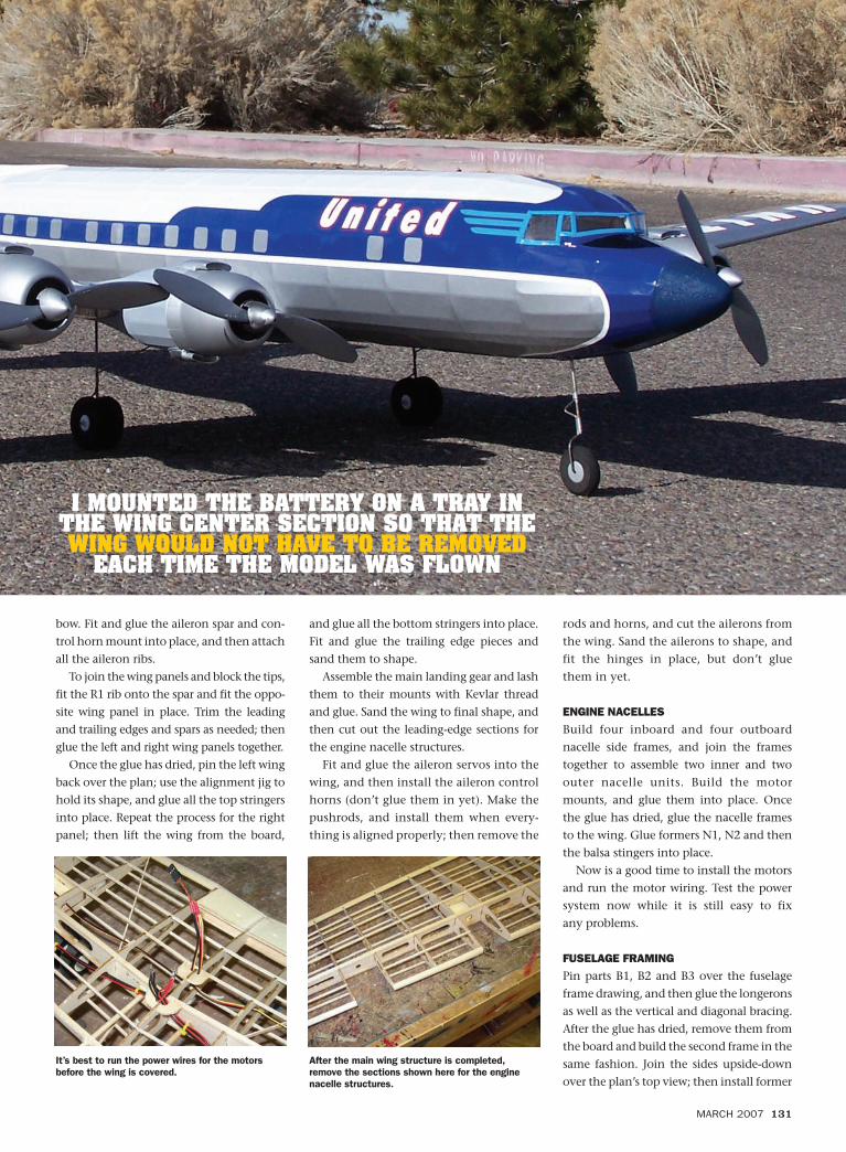
I MOUNTED THE BATTERY ON A TRAY INTHE WING CENTER SECTION SO THAT THEWING WOULD NOT HAVE TO BE REMOVED
EACH TIME THE MODEL WAS FLOWN
Contruct Redesign v3 2/9/09 4:18 PM Page 131
132 MODELAIRPLANENEWS.COM
WM1 and all of the cross-pieces and
diagonal bracing. Be sure not to build a
twist into the framework when you add
the diagonal bracing!
Build the nosewheel assembly, and
attach it to former NGM1. Glue the assem-
bly into place, and secure it with gussets.
Glue the servo mounts and rails into place,
and install the rudder and elevator servos.
Build the nosewheel steering pushrod
with a 1⁄16-inch carbon-fiber dowel. Lash a
threaded pushrod wire at one end and a
0.032-inch wire with a Z-bend at the other.
Wrap the wire ends with Kevlar thread, and
secure them with drops of thin CA. Con-
nect it to the steering arm, and adjust it so
that you achieve about 10 degrees of steer-
ing deflection on each side.
Glue the top and side fuselage formers
into place; then attach the balsa stringers
from former 3 aft. Add the stringers forward
of former 3 separately, and hand-fit them
against former 3 so that they blend
smoothly forward. Trim the stringers away
from the opening where the horizontal stab
passes through; then glue rudder mount B7
to the top of the fuselage.
TAIL SURFACES
Make the vertical-fin template using the
outlines shown on the fuselage side-view
drawing; then form the outline from two
laminations of balsa. Laminate two of the
D1 base strips together directly on top of
part B7. Clamp D1 into place on top of B7;
then frame the fin and rudder directly on
the fuselage. Use the rib alignment gauge to
set the rib angles; then fit and glue the balsa
diagonal bracing into place. Remove the
tail assembly from the fuselage, cut the rud-
der from the fin and sand it to shape. Fit the
hinges, but don’t glue them into place until
final assembly.
Make the horizontal stabilizer tips with
two laminations of balsa, and then build
the stab directly over the plans. Bend the
elevator joiner wire to shape and capture it
with ribs C10 and C4A. After you’ve fin-
ished framing, sand it to shape, and fit the
elevators to the elevator joiner.
Fit the vertical and horizontal stabilizers
onto the fuselage and tape them in place.
Install the pushrod and pushrod guide;
secure them at both ends and at several
places in between to prevent the pushrod
from flexing under load.
FINISHING THE FUSELAGE
Glue the bottom fuselage formers and
stringers into place from the wing trailing
edge aft. Glue the wing saddle formers in
place, and then fit and glue in the wing bolt
plate. Set the wing into the saddle, and drill
the hold-down dowel holes through former
WM1, the wing leading edge and into the
main spar shear web. Glue the dowels into
the wing, and refit the wing into the saddle.
Drill 9⁄64-inch holes in the bolt plate, and
thread the holes for the 8-32 wing bolts.
With the wing still in place, glue the cen-
ter section formers 5B and 5C in place, and
install the balsa stringers so that they flow
nicely into the center section. Use scrap
balsa to blend the hold-down bolt hole
openings flush with the stringers. Next, add
the remaining lower forward fuselage form-
ers and stringers, the blue foam nose cone
CONSTRUCTION DOUGLAS DC-6 MAINLINER
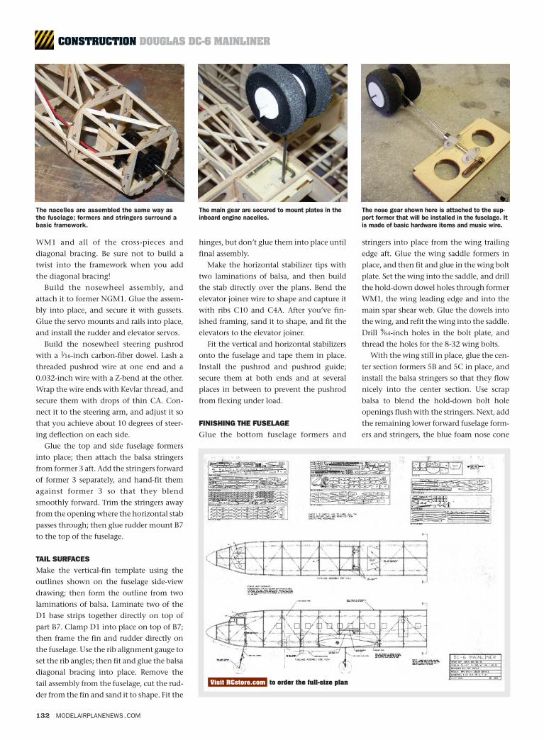
The nacelles are assembled the same way asthe fuselage; formers and stringers surround abasic framework.
The main gear are secured to mount plates in theinboard engine nacelles.
The nose gear shown here is attached to the sup-port former that will be installed in the fuselage. Itis made of basic hardware items and music wire.
Visit RCstore.com to order the full-size plan
Contruct Redesign v3 2/9/09 4:18 PM Page 132
134 MODELAIRPLANENEWS.COM
and balsa tail cone, and sand the entire
model smooth.
COVERING & FINISHING
I used Nelson LiteFilm, but Silkspan and
dope could also be used. Don’t use
MonoKote or UltraCote because they are
too heavy, and they shrink too much. With
the wing bolted into place, build the wing
root fairing using the detail drawings for
reference. This is undoubtedly the trickiest
part of the project, so take your time.
Glue the aileron, rudder and elevator
hinges in place, and then align and glue the
vertical and horizontal stabilizers to the
fuselage. Cut the horizontal stab and
engine nacelle fairings from heavy bond
paper using the patterns provided, and glue
them into place with Pacer 560 canopy
glue. Cut the windshield out of 0.005-inch
acetate and glue it into place.
Paint the model; then add the graphics
for your chosen trim scheme. If you decide
to go with the United Airlines color
scheme, a complete graphics package is
available from Callie Graphics. To finish it
all up, add the wheels, and touch it up as
needed. The cowls and air-inlet ducts are
available from Park Flyer Plastics. Paint
them and glue them into place with
canopy glue. Install the pushrods, and glue
the control horns in place.
Install the receiver and battery pack, and
balance the model. I mounted the battery
on a tray in the wing center section so that
the wing would not have to be removed
each time the model was flown.
IN THE AIR
Make sure that the control throws are
correct and that everything is moving in the
proper direction! The model taxis well, and
it tracks nice and true on the takeoff roll.
Point the model into the breeze, and apply
full power. Once it reaches flying speed, add
a little up-elevator to lift the model into the
air. This DC-6 is not underpowered, but like
its full-scale counterpart, it should be flown
on the wing, not on the props.
Trim the model for level flight. It is very
stable, and its control response is crisp and
precise. Due to the torque of the four
motors, turning the model left feels differ-
ent from turning it right. It’s no big deal
once you get used to it. Right turns require
a little more up-elevator to maintain alti-
tude. If the model is flown smoothly, there
is no adverse yaw with aileron deflection.
On approach, you’ll have to carry a good
bit of power for landing. If the throttle is
pulled back too much, the model will
descend very quickly. Hold the nose up
slightly with the elevator, and control the
rate of sink with power. Once a good rate of
descent is set up, the model will float just a
bit when it enters ground effect. Once the
wheels are on the ground, cut the power
and control the rollout with the rudder.
CONCLUSION
The DC-6 is a very smooth, stable, docile
flyer and has turned out to be everything I
had hoped for. As I mentioned earlier, this
project requires quite a bit of building, but
I guarantee it will be worth it the first time
you fly it!
See the Source Guide for manufacturers’ contact information.
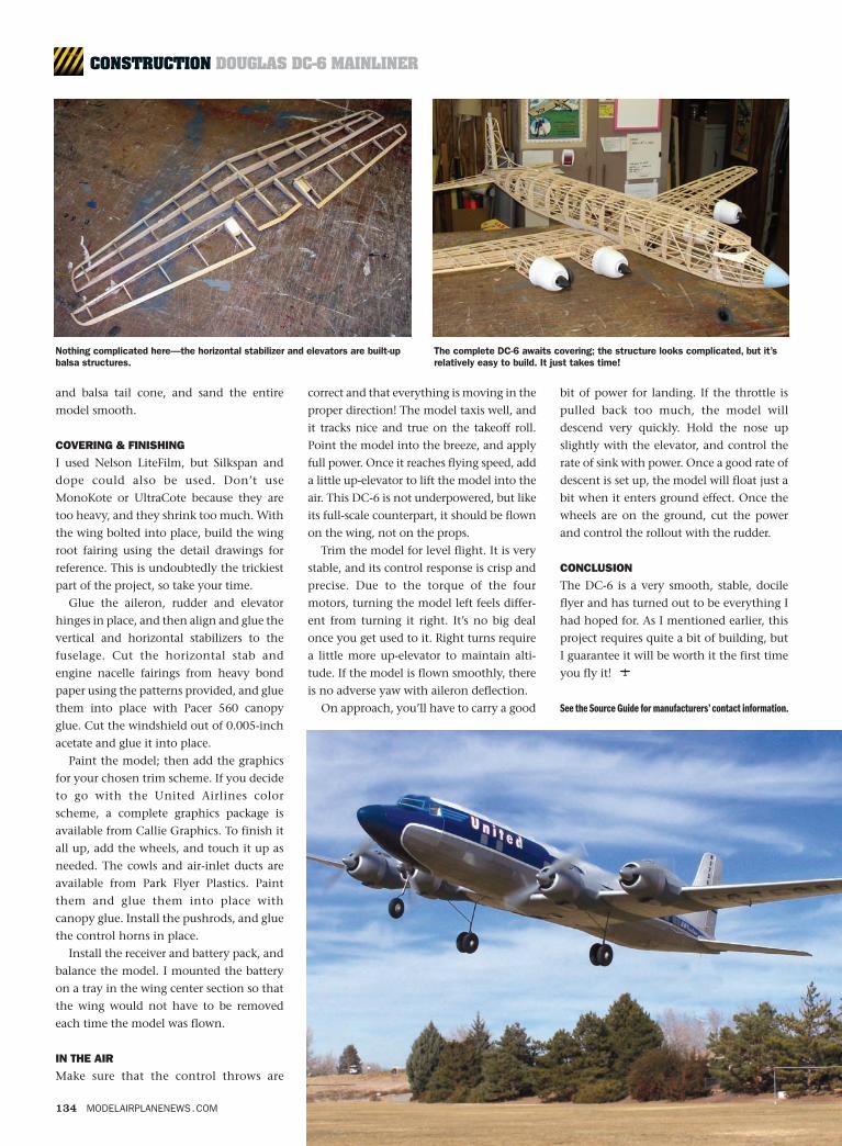
Nothing complicated here—the horizontal stabilizer and elevators are built-upbalsa structures.
The complete DC-6 awaits covering; the structure looks complicated, but it’srelatively easy to build. It just takes time!
CONSTRUCTION DOUGLAS DC-6 MAINLINER
Contruct Redesign v3 2/9/09 4:19 PM Page 134