Embed Size (px)
Citation preview
TEXSTEAM Pumps
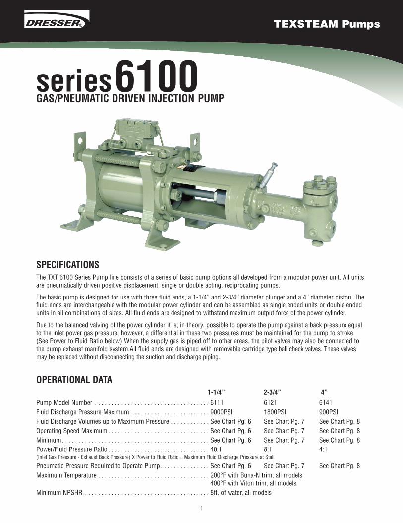
SPECIFICATIONSThe TXT 6100 Series Pump line consists of a series of basic pump options all developed from a modular power unit. All unitsare pneumatically driven positive displacement, single or double acting, reciprocating pumps.
The basic pump is designed for use with three fluid ends, a 1-1/4” and 2-3/4” diameter plunger and a 4” diameter piston. Thefluid ends are interchangeable with the modular power cylinder and can be assembled as single ended units or double endedunits in all combinations of sizes. All fluid ends are designed to withstand maximum output force of the power cylinder.
Due to the balanced valving of the power cylinder it is, in theory, possible to operate the pump against a back pressure equalto the inlet power gas pressure; however, a differential in these two pressures must be maintained for the pump to stroke.(See Power to Fluid Ratio below) When the supply gas is piped off to other areas, the pilot valves may also be connected tothe pump exhaust manifold system.All fluid ends are designed with removable cartridge type ball check valves. These valvesmay be replaced without disconnecting the suction and discharge piping.
OPERATIONAL DATA1-1/4” 2-3/4” 4”
1
Pump Model Number . . . . . . . . . . . . . . . . . . . . . . . . . . . . . . . . . . . 6111 6121 6141Fluid Discharge Pressure Maximum . . . . . . . . . . . . . . . . . . . . . . . . 9000PSI 1800PSI 900PSIFluid Discharge Volumes up to Maximum Pressure . . . . . . . . . . . . See Chart Pg. 6 See Chart Pg. 7 See Chart Pg. 8Operating Speed Maximum . . . . . . . . . . . . . . . . . . . . . . . . . . . . . . . See Chart Pg. 6 See Chart Pg. 7 See Chart Pg. 8Minimum. . . . . . . . . . . . . . . . . . . . . . . . . . . . . . . . . . . . . . . . . . . . . See Chart Pg. 6 See Chart Pg. 7 See Chart Pg. 8Power/Fluid Pressure Ratio . . . . . . . . . . . . . . . . . . . . . . . . . . . . . . . 40:1 8:1 4:1(Inlet Gas Pressure - Exhaust Back Pressure) X Power to Fluid Ratio = Maximum Fluid Discharge Pressure at Stall
Pneumatic Pressure Required to Operate Pump . . . . . . . . . . . . . . . See Chart Pg. 6 See Chart Pg. 7 See Chart Pg. 8Maximum Temperature . . . . . . . . . . . . . . . . . . . . . . . . . . . . . . . . . . 200°F with Buna-N trim, all models
400°F with Viton trim, all modelsMinimum NPSHR . . . . . . . . . . . . . . . . . . . . . . . . . . . . . . . . . . . . . . 8ft. of water, all models
series6100GAS/PNEUMATIC DRIVEN INJECTION PUMP
2
INSTALLATION AND OPERATING INSTRUCTIONS
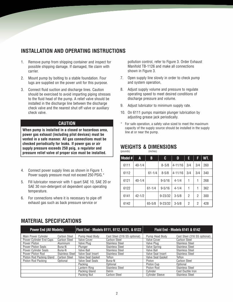
1. Remove pump from shipping container and inspect forpossible shipping damage. If damaged, file claim withcarrier.
2. Mount pump by bolting to a stable foundation. Fourlugs are supplied on the power unit for this purpose.
3. Connect fluid suction and discharge lines. Cautionshould be exercised to avoid imparting piping stressesto the fluid head of the pump. A relief valve should beinstalled in the discharge line between the dischargecheck valve and the nearest shut off valve or auxiliarycheck valve.
CAUTIONWhen pump is installed in a closed or hazardous area,power gas exhaust (including pilot devices) must bevented in a safe manner. All gas connections must bechecked periodically for leaks. If power gas or airsupply pressure exceeds 250 psig, a regulator andpressure relief valve of proper size must be installed.
4. Connect power supply lines as shown in Figure 1.Power supply pressure must not exceed 250 PSIG.*
5. Fill lubricator reservoir with 1 quart SAE 10, SAE 20 orSAE 30 non-detergent oil dependent upon operatingtemperature.
6. For connections where it is necessary to pipe offexhaust gas such as back pressure service or
pollution control, refer to Figure 3. Order ExhaustManifold TB-1126 and make all connectionsshown in Figure 3.
7. Open supply line slowly in order to check pumpand system operation,
8. Adjust supply volume and pressure to regulateoperating speed to meet desired conditions ofdischarge pressure and volume.
9. Adjust lubricator to minimum supply rate.
10. On 6111 pumps maintain plunger lubrication byadjusting grease jack periodically.
* For safe operation, a safety valve sized to meet the maximumcapacity of the supply source should be installed in the supplyline at or near the pump.
WEIGHTS & DIMENSIONS(pounds) (inches)
Model # A B C D E F WT.
6111 40-1/4 8- 5/8 4-11/16 3/4 3/4 260
6112 61-1/4 8-5/8 4-11/16 3/4 3/4 340
6121 40-1/4 9-5/16 4-1/4 1 1 268
6122 61-1/4 9-5/16 4-1/4 1 1 362
6141 42-1/2 9-23/32 3-5/8 2 2 300
6142 65-5/8 9-23/32 3-5/8 2 2 428
MATERIAL SPECIFICATIONS
Power End (All Models) Fluid End - Models 6111, 6112, 6121, & 6122 Fluid End - Models 6141 & 6142
Main Power Cylinder Carbon SteelPower Cylinder End Caps Carbon SteelPower Piston AluminumPower Piston Seals Buna-NPower Cylinder Seals Buna-NPower Piston Rod Stainless SteelPiston Rod Packing Gland Carbon SteelPiston Rod Packing Optional
Pump Head Body Cast Steel (316 SS optional)Valve Cover Carbon SteelValve Plug Stainless SteelPlunger Stainless SteelValve Ball Stainless SteelValve Seat Insert Stainless SteelValve Seat Gasket TeflonValve Seat Seals Buna-NPacking OptionalLantern Ring Stainless SteelPacking Gland DelrinPacking Nut Carbon Steel
Pump Head Body Cast Steel (316 SS optional)Valve Cover Carbon SteelValve Plug Stainless SteelValve Spring Stainless SteelValve Ball Stainless SteelValve Seat Insert Stainless SteelValve Seat Gasket TeflonPiston Carbon SteelPiston Cup OptionalPiston Rod Stainless SteelCylinder Cast Ductile IronCylinder Sleeve Stainless Steel
3
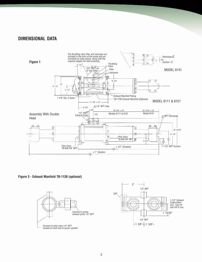
DIMENSIONAL DATA
3”
1 15/32”
1 3/8” 1 3/8”
14 1/2”13”
6 1/2”
3 1/2”12 1/2”
2”
16 3/4”
8 5/8”
17 3/8” ± 1/4”
1 3/8”
1 3/8”
30 5/8” ± 1/2”
B
A
6 3/4” D
F
C
13 1/8”
E
32 3/16” ± 1/2”
16 15/16”
1”2 5/8”
Figure 1
Assembly With DoubleHead
MODEL 6141
MODEL 6111 & 6121
Figure 3 - Exhaust Manifold TB-1126 (optional)
Connect to pilot valve 1/4” NPTlocated on each end of power cylinder
Connect to pumpexhaust ports 1/2” NPT
CAP
1-1/2” ExhaustOutlet eitherend. Cap offend not in use.
1/4” NPT
1/4” NPT
± 1” (Duplex)
± 1/2” (Simplex)Pilot ValveTB-928 3/8” NPT
Pilot ValveTB-928 3/8” NPT
NPT Suction
NPT DischargeModel 6141Models 6111 & 61211/2” FNPT
Exhaust Ports
C 1/2” NPT InletL
1-1/8” Dia. 4 Holes TB-1126 Exhaust Manifold (Optional)Exhaust Manifold Piping
LubricatorFilter
ThrottlingValve
3/4” FNPT Airor Gas Inlet
The throttling valve filter and lubricator areincluded in the price of the pump and arefurnished as loose pieces, along with therequired nipples for field assembly.
Discharge E
Suction F
TB-928 Pilot Valve (Two Required)
4
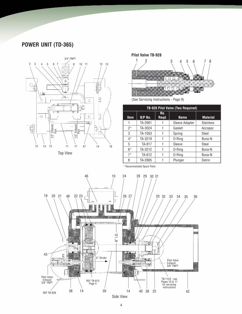
POWER UNIT (TD-365)
2 3 4 5 6 7 8 10 11
12 14 15 11 17 47 14 18
12 13
43
38 14 1439 40 38 25 42
8”I.D
.
26 27 20 32 33 34 35 36
10 24 28 29 30 3146
19 20 21 48 22 23
Top View
Side View
3/4” FNPT
1/2”
Exha
ust
Port
Port
1/2”
Exha
ust
REF TB-813Page 4
Pilot ValveExhaust3/8” FNPT
TB-1124 - seePages 10 & 11for servicinginstructions
6” Stroke
Pilot ValveExhaust
3/8” FNPT
REF TB-928
1 2 3 4 5 6 7 8
(See Servicing Instructions - Page 9)
Pilot Valve TB-928
No.Item B/P No. Reqd. Name Material1 TA-2901 1 Sleeve Adapter Stainless2* TA-3024 1 Gasket Accopac3 TA-1053 1 Spring Steel4* TA-3219 1 O-Ring Buna-N5 TA-817 1 Sleeve Steel6* TA-3212 1 O-Ring Buna-N7* TA-612 1 O-Ring Buna-N8 TA-2805 1 Plunger Delrin
* Recommended Spare Parts
TB-1510 Spool Valve
5
4
3
1
2
5
4
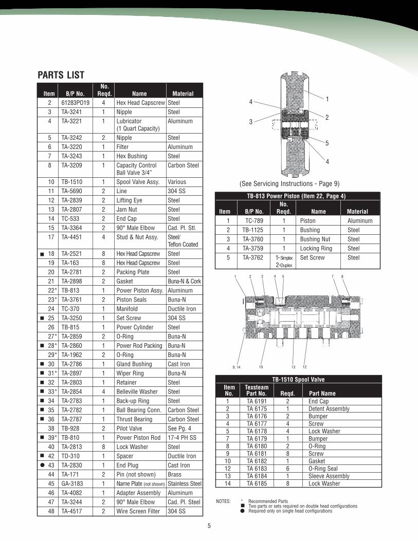
(See Servicing Instructions - Page 9)
No.Item B/P No. Reqd. Name Material
1 TC-789 1 Piston Aluminum2 TB-1125 1 Bushing Steel3 TA-3760 1 Bushing Nut Steel4 TA-3759 1 Locking Ring Steel5 TA-3762 1-Simplex Set Screw Steel
2-Duplex
1 2 3 4 5 7 8
10 13 129, 14
2 61283PO19 4 Hex Head Capscrew Steel3 TA-3241 1 Nipple Steel4 TA-3221 1 Lubricator Aluminum
(1 Quart Capacity)5 TA-3242 2 Nipple Steel6 TA-3220 1 Filter Aluminum7 TA-3243 1 Hex Bushing Steel8 TA-3209 1 Capacity Control Carbon Steel
Ball Valve 3/4”10 TB-1510 1 Spool Valve Assy. Various11 TA-5690 2 Line 304 SS12 TA-2839 2 Lifting Eye Steel13 TA-2807 2 Jam Nut Steel14 TC-533 2 End Cap Steel15 TA-3364 2 90° Male Elbow Cad. Pl. Stl.17 TA-4451 4 Stud & Nut Assy. Steel/
Teflon Coated18 TA-2521 8 Hex Head Capscrew Steel19 TA-163 8 Hex Head Capscrew Steel20 TA-2781 2 Packing Plate Steel21 TA-2898 2 Gasket Buna-N& Cork22* TB-813 1 Power Piston Assy. Aluminum23* TA-3761 2 Piston Seals Buna-N24 TC-370 1 Manifold Ductile Iron25 TA-3250 1 Set Screw 304 SS26 TB-815 1 Power Cylinder Steel27* TA-2859 2 O-Ring Buna-N28* TA-2860 1 Power Rod Packing Buna-N29* TA-1962 2 O-Ring Buna-N30 TA-2786 1 Gland Bushing Cast Iron31* TA-2897 1 Wiper Ring Buna-N32 TA-2803 1 Retainer Steel33* TA-2854 4 Belleville Washer Steel34 TA-2783 1 Back-up Ring Steel35 TA-2782 1 Ball Bearing Conn. Carbon Steel36 TA-2787 1 Thrust Bearing Carbon Steel38 TB-928 2 Pilot Valve See Pg. 439* TB-810 1 Power Piston Rod 17-4 PH SS40 TA-2813 8 Lock Washer Steel42 TD-310 1 Spacer Ductile Iron43 TA-2830 1 End Plug Cast Iron44 TA-171 2 Pin (not shown) Brass45 GA-3183 1 Name Plate (not shown) Stainless Steel46 TA-4082 1 Adapter Assembly Aluminum47 TA-3244 2 90° Male Elbow Cad. Pl. Steel48 TA-4517 2 Wire Screen Filter 304 SS
PARTS LIST
NOTES: * Recommended PartsTwo parts or sets required on double head configurationsRequired only on single head configurations
1 TA 6191 2 End Cap2 TA 6175 1 Detent Assembly3 TA 6176 2 Bumper4 TA 6177 4 Screw5 TA 6178 4 Lock Washer7 TA 6179 1 Bumper8 TA 6180 2 O-Ring9 TA 6181 8 Screw10 TA 6182 1 Gasket12 TA 6183 6 O-Ring Seal13 TA 6184 1 Sleeve Assembly14 TA 6185 8 Lock Washer
TB-813 Power Piston (Item 22, Page 4)
No.Item B/P No. Reqd. Name Material
Item TexsteamNo. Part No. Reqd. Part Name
1
2
3
4
5
5
8 6
78
105
11
8
10
12 13 14 15 20 22 23 16 17 18 19
21
9
3/4” Suctionand Discharge
Stick Lube (White)TA-3179, One Stick
TA-3179-2,(72 Stick Carton)
6
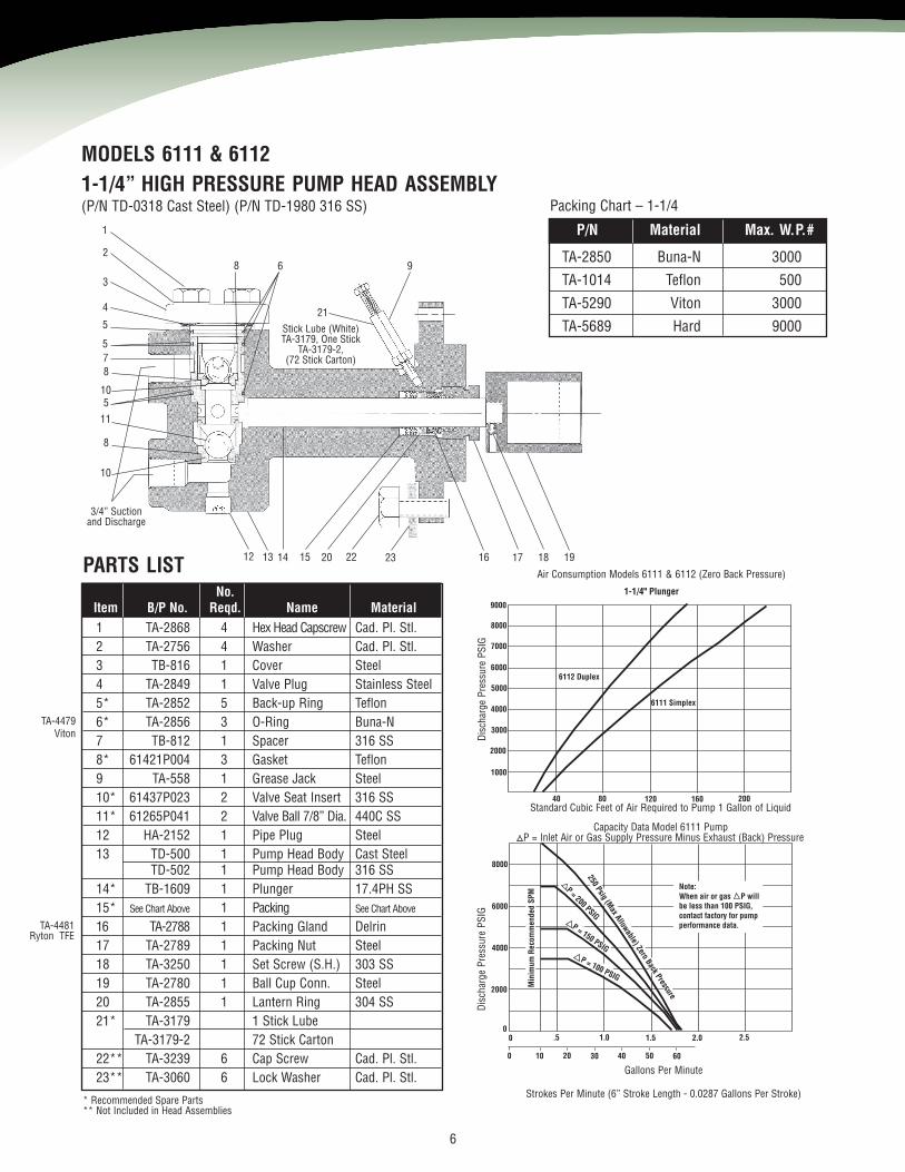
MODELS 6111 & 61121-1/4” HIGH PRESSURE PUMP HEAD ASSEMBLY
9000
8000
40
7000
6000
5000
4000
3000
2000
1000
80 120 160 200
6112 Duplex
6111 Simplex
1-1/4" Plunger
8000
.5
6000
4000
2000
1.0 1.5 2.0 2.5
Min
imum
Rec
omm
ende
dSP
M
250Psig
(Max Allowable), Zero
Back Pressure
P = 200 PSIGP = 150 PSIG
P = 100 PSIG
Min
imum
Rec
omm
ende
dSP
M
250Psig
(Max Allowable) Zero
Back Pressure
P = 200 PSIGP = 150 PSIG
P = 100 PSIG
Note:When air or gas P willbe less than 100 PSIG, contact factory for pump performance data.
00
0 10 20 30 40 50 60
P/N Material Max. W.P.#
TA-2850 Buna-N 3000
TA-1014 Teflon 500
TA-5290 Viton 3000
TA-5689 Hard 9000
Packing Chart – 1-1/4
No.Item B/P No. Reqd. Name Material1 TA-2868 4 Hex Head Capscrew Cad. Pl. Stl.2 TA-2756 4 Washer Cad. Pl. Stl.3 TB-816 1 Cover Steel4 TA-2849 1 Valve Plug Stainless Steel5* TA-2852 5 Back-up Ring Teflon6* TA-2856 3 O-Ring Buna-N7 TB-812 1 Spacer 316 SS8* 61421P004 3 Gasket Teflon9 TA-558 1 Grease Jack Steel10* 61437P023 2 Valve Seat Insert 316 SS11* 61265P041 2 Valve Ball 7/8” Dia. 440C SS12 HA-2152 1 Pipe Plug Steel13 TD-500 1 Pump Head Body Cast Steel
TD-502 1 Pump Head Body 316 SS14* TB-1609 1 Plunger 17.4PH SS15* See Chart Above 1 Packing See Chart Above
16 TA-2788 1 Packing Gland Delrin17 TA-2789 1 Packing Nut Steel18 TA-3250 1 Set Screw (S.H.) 303 SS19 TA-2780 1 Ball Cup Conn. Steel20 TA-2855 1 Lantern Ring 304 SS21* TA-3179 1 Stick Lube
TA-3179-2 72 Stick Carton22** TA-3239 6 Cap Screw Cad. Pl. Stl.23** TA-3060 6 Lock Washer Cad. Pl. Stl.
PARTS LIST
* Recommended Spare Parts** Not Included in Head Assemblies
Air Consumption Models 6111 & 6112 (Zero Back Pressure)
Standard Cubic Feet of Air Required to Pump 1 Gallon of Liquid
Capacity Data Model 6111 PumpP = Inlet Air or Gas Supply Pressure Minus Exhaust (Back) Pressure
Strokes Per Minute (6” Stroke Length - 0.0287 Gallons Per Stroke)
Gallons Per Minute
Disch
arge
Pres
sure
PSIG
Disch
arge
Pres
sure
PSIG
(P/N TD-0318 Cast Steel) (P/N TD-1980 316 SS)
TA-4479Viton
TA-4481Ryton TFE
7
1
2345
6
7
5
7
6
7
5
9 16 17
15
14
11 12 1310
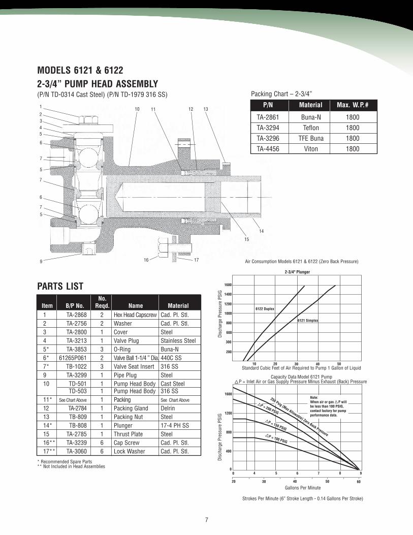
MODELS 6121 & 61222-3/4” PUMP HEAD ASSEMBLY
1600
10
1400
1200
1000
800
600
300
200
20 30 40 50
6122 Duplex
6121 Simplex
2-3/4" Plunger
1600
4
1200
800
400
5 6 7 8
250 Psig (Max Allowable), Zero Back Pressure
250 Psig (Max Allowable) Zero Back Pressure
Note: When air or gas P will be less than 100 PSIG,contact factory for pump performance data.
P = 200 PSIG
P = 200 PSIG
P = 100 PSIGP = 100 PSIG
P = 150 PSIG
P = 150 PSIG
00
20 30 40 60
9
50
P/N Material Max. W.P.#
TA-2861 Buna-N 1800
TA-3294 Teflon 1800
TA-3296 TFE Buna 1800
TA-4456 Viton 1800
Packing Chart – 2-3/4”
No.Item B/P No. Reqd. Name Material1 TA-2868 2 Hex Head Capscrew Cad. Pl. Stl.2 TA-2756 2 Washer Cad. Pl. Stl.3 TA-2800 1 Cover Steel4 TA-3213 1 Valve Plug Stainless Steel5* TA-3853 3 O-Ring Buna-N6* 61265P061 2 Valve Ball 1-1/4 ” Dia. 440C SS7* TB-1022 3 Valve Seat Insert 316 SS9 TA-3299 1 Pipe Plug Steel10 TD-501 1 Pump Head Body Cast Steel
TD-503 1 Pump Head Body 316 SS11* See Chart Above 1 Packing See Chart Above
12 TA-2784 1 Packing Gland Delrin13 TB-809 1 Packing Nut Steel14* TB-808 1 Plunger 17-4 PH SS15 TA-2785 1 Thrust Plate Steel16** TA-3239 6 Cap Screw Cad. Pl. Stl.17** TA-3060 6 Lock Washer Cad. Pl. Stl.
PARTS LIST
* Recommended Spare Parts** Not Included in Head Assemblies
Air Consumption Models 6121 & 6122 (Zero Back Pressure)
Standard Cubic Feet of Air Required to Pump 1 Gallon of Liquid
Capacity Data Model 6121 PumpP = Inlet Air or Gas Supply Pressure Minus Exhaust (Back) Pressure
Strokes Per Minute (6” Stroke Length - 0.14 Gallons Per Stroke)
Gallons Per Minute
Disch
arge
Pres
sure
PSIG
Disch
arge
Pres
sure
PSIG
(P/N TD-0314 Cast Steel) (P/N TD-1979 316 SS)
1 2 3 4 5 6 7 8 9 5 11 12 13 14 15 16 17 18 19 20 21
27 16 18 2124 25
8A 8B 9A29 2622 23
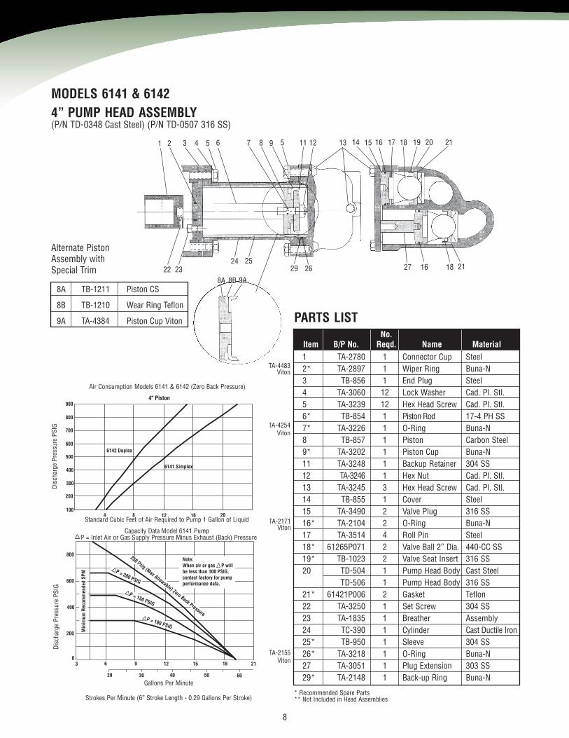
MODELS 6141 & 61424” PUMP HEAD ASSEMBLY
800
4
700
600
500
400
300
200
1008 12 16 20
6142 Duplex
6141 Simplex
4" Piston
800
6
600
400
200
9 12 15 18
250 Psig (Max Allowable), Zero Back Pressure
250 Psig (Max Allowable) Zero Back Pressure
Note:When air or gas P willbe less than 100 PSIG,contact factory for pumpperformance data.
P = 200 PSIG
P = 200 PSIG
P = 100 PSIGP = 100 PSIG
P = 150 PSIG
P = 150 PSIG
03
20 30 40 60
21
50
900
Min
imum
Rec
omm
ende
dSP
MM
inim
umR
ecom
men
ded
SPM
No.Item B/P No. Reqd. Name Material1 TA-2780 1 Connector Cup Steel2* TA-2897 1 Wiper Ring Buna-N3 TB-856 1 End Plug Steel4 TA-3060 12 Lock Washer Cad. Pl. Stl.5 TA-3239 12 Hex Head Screw Cad. Pl. Stl.6* TB-854 1 Piston Rod 17-4 PH SS7* TA-3226 1 O-Ring Buna-N8 TB-857 1 Piston Carbon Steel9* TA-3202 1 Piston Cup Buna-N11 TA-3248 1 Backup Retainer 304 SS12 TA-3246 1 Hex Nut Cad. Pl. Stl.13 TA-3245 3 Hex Head Screw Cad. Pl. Stl.14 TB-855 1 Cover Steel15 TA-3490 2 Valve Plug 316 SS16* TA-2104 2 O-Ring Buna-N17 TA-3514 4 Roll Pin Steel18* 61265P071 2 Valve Ball 2” Dia. 440-CC SS19* TB-1023 2 Valve Seat Insert 316 SS20 TD-504 1 Pump Head Body Cast Steel
TD-506 1 Pump Head Body 316 SS21* 61421P006 2 Gasket Teflon22 TA-3250 1 Set Screw 304 SS23 TA-1835 1 Breather Assembly24 TC-390 1 Cylinder Cast Ductile Iron25* TB-950 1 Sleeve 304 SS26* TA-3218 1 O-Ring Buna-N27 TA-3051 1 Plug Extension 303 SS29* TA-2148 1 Back-up Ring Buna-N
PARTS LIST
* Recommended Spare Parts** Not Included in Head Assemblies
Air Consumption Models 6141 & 6142 (Zero Back Pressure)
Standard Cubic Feet of Air Required to Pump 1 Gallon of Liquid
Capacity Data Model 6141 PumpP = Inlet Air or Gas Supply Pressure Minus Exhaust (Back) Pressure
Strokes Per Minute (6” Stroke Length - 0.29 Gallons Per Stroke)
Gallons Per Minute
Disch
arge
Pres
sure
PSIG
Disch
arge
Pres
sure
PSIG
8
(P/N TD-0348 Cast Steel) (P/N TD-0507 316 SS)
8A TB-1211 Piston CS
8B TB-1210 Wear Ring Teflon
9A TA-4384 Piston Cup Viton
Alternate PistonAssembly withSpecial Trim
TA-4483Viton
TA-4254Viton
TA-2171Viton
TA-2155Viton
9
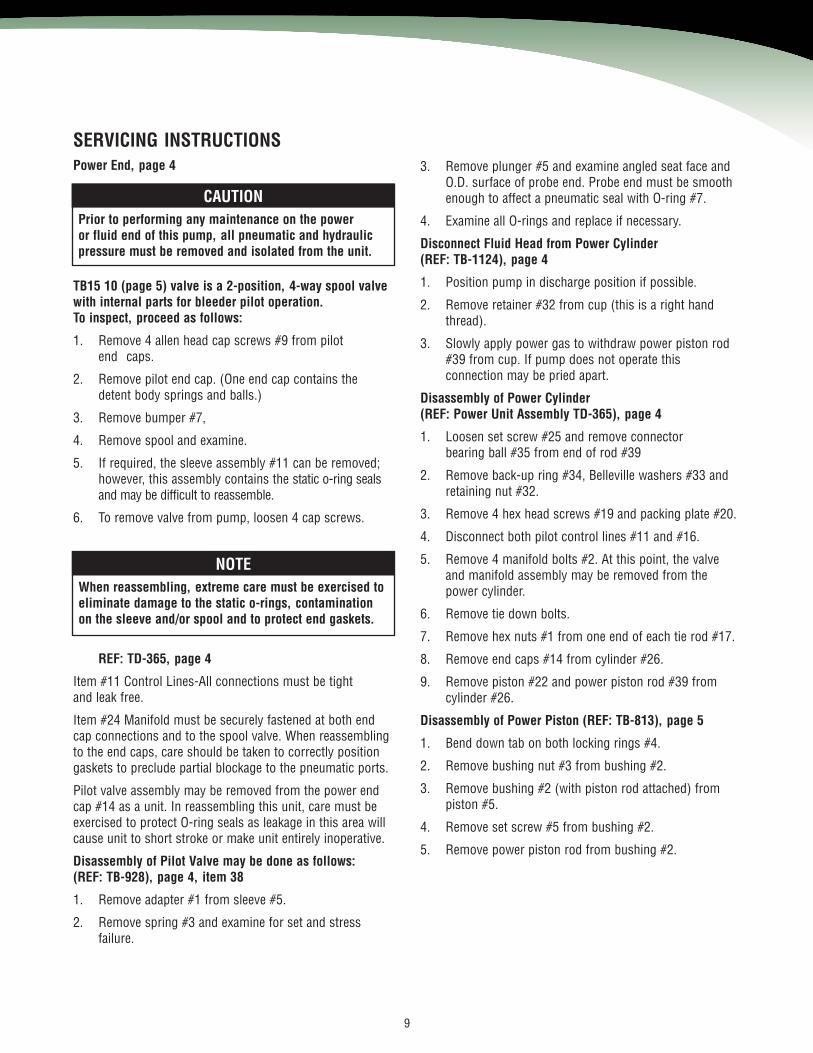
TB15 10 (page 5) valve is a 2-position, 4-way spool valvewith internal parts for bleeder pilot operation.To inspect, proceed as follows:
1. Remove 4 allen head cap screws #9 from pilotend caps.
2. Remove pilot end cap. (One end cap contains thedetent body springs and balls.)
3. Remove bumper #7,
4. Remove spool and examine.
5. If required, the sleeve assembly #11 can be removed;however, this assembly contains the static o-ring sealsand may be difficult to reassemble.
6. To remove valve from pump, loosen 4 cap screws.
3. Remove plunger #5 and examine angled seat face andO.D. surface of probe end. Probe end must be smoothenough to affect a pneumatic seal with O-ring #7.
4. Examine all O-rings and replace if necessary.
Disconnect Fluid Head from Power Cylinder(REF: TB-1124), page 4
1. Position pump in discharge position if possible.
2. Remove retainer #32 from cup (this is a right handthread).
3. Slowly apply power gas to withdraw power piston rod#39 from cup. If pump does not operate thisconnection may be pried apart.
Disassembly of Power Cylinder(REF: Power Unit Assembly TD-365), page 4
1. Loosen set screw #25 and remove connectorbearing ball #35 from end of rod #39
2. Remove back-up ring #34, Belleville washers #33 andretaining nut #32.
3. Remove 4 hex head screws #19 and packing plate #20.
4. Disconnect both pilot control lines #11 and #16.
5. Remove 4 manifold bolts #2. At this point, the valveand manifold assembly may be removed from thepower cylinder.
6. Remove tie down bolts.
7. Remove hex nuts #1 from one end of each tie rod #17.
8. Remove end caps #14 from cylinder #26.
9. Remove piston #22 and power piston rod #39 fromcylinder #26.
Disassembly of Power Piston (REF: TB-813), page 5
1. Bend down tab on both locking rings #4.
2. Remove bushing nut #3 from bushing #2.
3. Remove bushing #2 (with piston rod attached) frompiston #5.
4. Remove set screw #5 from bushing #2.
5. Remove power piston rod from bushing #2.
SERVICING INSTRUCTIONSPower End, page 4
REF: TD-365, page 4
Item #11 Control Lines-All connections must be tightand leak free.
Item #24 Manifold must be securely fastened at both endcap connections and to the spool valve. When reassemblingto the end caps, care should be taken to correctly positiongaskets to preclude partial blockage to the pneumatic ports.
Pilot valve assembly may be removed from the power endcap #14 as a unit. In reassembling this unit, care must beexercised to protect O-ring seals as leakage in this area willcause unit to short stroke or make unit entirely inoperative.
Disassembly of Pilot Valve may be done as follows:(REF: TB-928), page 4, item 38
1. Remove adapter #1 from sleeve #5.
2. Remove spring #3 and examine for set and stressfailure.
CAUTIONPrior to performing any maintenance on the poweror fluid end of this pump, all pneumatic and hydraulicpressure must be removed and isolated from the unit.
NOTEWhen reassembling, extreme care must be exercised toeliminate damage to the static o-rings, contaminationon the sleeve and/or spool and to protect end gaskets.
10
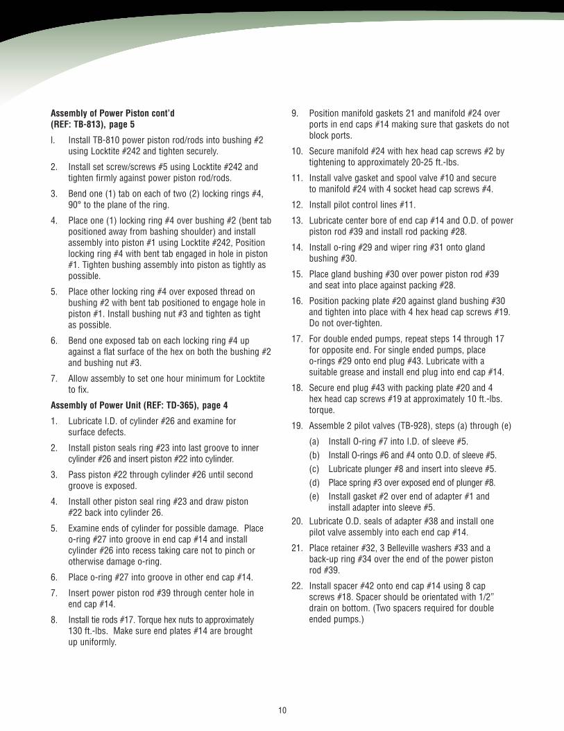
Assembly of Power Piston cont’d(REF: TB-813), page 5
l. Install TB-810 power piston rod/rods into bushing #2using Locktite #242 and tighten securely.
2. Install set screw/screws #5 using Locktite #242 andtighten firmly against power piston rod/rods.
3. Bend one (1) tab on each of two (2) locking rings #4,90° to the plane of the ring.
4. Place one (1) locking ring #4 over bushing #2 (bent tabpositioned away from bashing shoulder) and installassembly into piston #1 using Locktite #242, Positionlocking ring #4 with bent tab engaged in hole in piston#1. Tighten bushing assembly into piston as tightly aspossible.
5. Place other locking ring #4 over exposed thread onbushing #2 with bent tab positioned to engage hole inpiston #1. Install bushing nut #3 and tighten as tightas possible.
6. Bend one exposed tab on each locking ring #4 upagainst a flat surface of the hex on both the bushing #2and bushing nut #3.
7. Allow assembly to set one hour minimum for Locktiteto fix.
Assembly of Power Unit (REF: TD-365), page 4
1. Lubricate I.D. of cylinder #26 and examine forsurface defects.
2. Install piston seals ring #23 into last groove to innercylinder #26 and insert piston #22 into cylinder.
3. Pass piston #22 through cylinder #26 until secondgroove is exposed.
4. Install other piston seal ring #23 and draw piston#22 back into cylinder 26.
5. Examine ends of cylinder for possible damage. Placeo-ring #27 into groove in end cap #14 and installcylinder #26 into recess taking care not to pinch orotherwise damage o-ring.
6. Place o-ring #27 into groove in other end cap #14.
7. Insert power piston rod #39 through center hole inend cap #14.
8. Install tie rods #17. Torque hex nuts to approximately130 ft.-lbs. Make sure end plates #14 are broughtup uniformly.
9. Position manifold gaskets 21 and manifold #24 overports in end caps #14 making sure that gaskets do notblock ports.
10. Secure manifold #24 with hex head cap screws #2 bytightening to approximately 20-25 ft.-lbs.
11. Install valve gasket and spool valve #10 and secureto manifold #24 with 4 socket head cap screws #4.
12. Install pilot control lines #11.
13. Lubricate center bore of end cap #14 and O.D. of powerpiston rod #39 and install rod packing #28.
14. Install o-ring #29 and wiper ring #31 onto glandbushing #30.
15. Place gland bushing #30 over power piston rod #39and seat into place against packing #28.
16. Position packing plate #20 against gland bushing #30and tighten into place with 4 hex head cap screws #19.Do not over-tighten.
17. For double ended pumps, repeat steps 14 through 17for opposite end. For single ended pumps, placeo-rings #29 onto end plug #43. Lubricate with asuitable grease and install end plug into end cap #14.
18. Secure end plug #43 with packing plate #20 and 4hex head cap screws #19 at approximately 10 ft.-lbs.torque.
19. Assemble 2 pilot valves (TB-928), steps (a) through (e)
(a) Install O-ring #7 into I.D. of sleeve #5.(b) Install O-rings #6 and #4 onto O.D. of sleeve #5.(c) Lubricate plunger #8 and insert into sleeve #5.(d) Place spring #3 over exposed end of plunger #8.(e) Install gasket #2 over end of adapter #1 and
install adapter into sleeve #5.20. Lubricate O.D. seals of adapter #38 and install one
pilot valve assembly into each end cap #14.
21. Place retainer #32, 3 Belleville washers #33 and aback-up ring #34 over the end of the power pistonrod #39.
22. Install spacer #42 onto end cap #14 using 8 capscrews #18. Spacer should be orientated with 1/2”drain on bottom. (Two spacers required for doubleended pumps.)
11
Assembly Procedures of Head Assemblies 6111 HeadAssembly (REF: page 6)
l. Examine head body #13 to make sure valve cageseating surface and packing areas are free of nicks andburrs. Check all thread areas for condition of threads.
2. Install seal #8 onto seal surface.
3. Install lower valve cage #10 and ball #11 into valvebore of pump head #13.
4. Install O-rings #6 and back-up rings #5 onto spacercage #7 and lubricate seal area.
5. Install spacer cage #7 from step 4 into pump head #13.
6. Install seal #8 onto seal surface inside spacer cage #7.
7. Install upper valve cage #l0 and ball #11 into spacercage.
6111 Head Assembly cont’d. (REF: page 6)
8. Install o-ring 6 and back-up ring #5 onto valve plug #4.
9. Place seal #8 on top surface of upper valve cage #11.
10. Install valve plug #4 from step 8 into top of pump body.
11. Place cover plate #3 over valve plug #4 and securecover using 4 hex head cap screws #1 with lockwashers #2. Torque to approximately 30-40 ft-lbs.
12. Install pipe plug #12 using Locktite pipe sealant orequal.
13. Install packing #15 and lantern ring #20.
14. Place packing gland #16 into packing gland nut #17and thread assembly into pump body #13. Do nottighten more than hand tight.
15. Assemble ball connector cup #19 onto plunger #14using Locktite 222 if available. Secure connection withset screw #18.
16. Lubricate plunger #14 and insert through packing endof pump head #13.
17. Install grease jack #9, containing 2 sticks of Chennolalubricant.
6121 Head Assembly (REF: page 7)
1. Examine head body #10 to insure valve cage seatingsurfaces and packing areas are free of nicks and burrs.Check threaded areas for thread condition.
2. Install seal #5 onto lower seal surface.
3. Install lower valve cage #7 and valve ball #6 into pumphead #10.
4. Install spacer cage #7.
5. Install seal #5 onto top surface of spacer cage #7.
6. Install top valve cage #7 and valve ball #6 into pumphead #10.
7. Place top seal #5 onto top surface of top valve cage #7.
8. Install valve plug #4.
9. Position cover plate #3 over valve plug #4 and secureusing 2 hex head cap screws #1 with locknuts #2.Torque to approximately 30-40 ft-lbs.
10. Install pipe plug #9 using Locktite pipe seal or equal.
11. Insert packing #11 into packing bore of pumpbody #10.
12. Install packing gland #12 into packing gland nut #13and thread assembly into pump cody #10. Do nottighten more than hand tight.
13. Lubricate O.D. of plunger #14 and insert throughpacking end of pump head #10.
6141 Head Assembly (REF: page 8)
1. Examine pump head #20 to insure valve cage sealingsurfaces and cylinder sealing surface are free ofdefects. Check thread areas for thread condition.
2. Install seals #21 onto lower seal surfaces of eachcavity in pump head #20.
3. Install valve ball #18 into valve cage #19. Insert valveplug #15 into valve cage #19 and fasten with roll pin#17. Install o-ring #16 onto valve plug #15 and lubricate each cavity in pump head #20.
4. Insert plug & insert assembly into each cavity of pumphead #20.
5. Install plug #27 as shown.NOTE
When using teflon packing, replace grease jackwith pipe plug.
10. Position end plug #3 onto spacer and position cylinder#24 using 6 screws #5 and 6 washers #4. Flat end ofcylinder must be used. Do not tighten this joint, leave atleast 1/4” gap.
11. Install sleeve #25 into cylinder #24.
12. With piston rod #6 moved to full forward position,install o-ring #7, piston #8, piston cup #9, back-upretainer #11 and nut #12.
13. Install o-ring #26 and back up #29 onto end ofsleeve #25,
14. Place assembled pump head from step 10 over end ofsleeve #25. Secure cylinder #24 to pump head using 6screws #5 and 6 washers #4, This joint should bebrought face to face. If a gap exists, loosen joint madein step 13.
15. After tightening cylinder to head connection, thentighten cylinder to spacer connection. A gap will exist atthis joint - do not over-tighten.
Assembly of Fluid End to Power Units (REF: page 4)
1. Insert ball joint thrust bearing #36 into connector cup.
2. Insert connector bearing ball #35 (on end ofpreassembled power piston rod #39) into connectorcup and tighten retainer #32. Retainer should shoulderagainst end of connector cup without excessive pressure.
12. Install packing gland #12 into packing gland nut #13and thread assembly into pump cody #10. Do nottighten more than hand tight.
13. Lubricate O.D. of plunger #14 and insert throughpacking end of pump head #10.
6141 Head Assembly (REF: page 8)
1. Examine pump head #20 to insure valve cage sealingsurfaces and cylinder sealing surface are free ofdefects. Check thread areas for thread condition.
2. Install seals #21 onto lower seal surfaces of eachcavity in pump head #20.
3. Install valve ball #18 into valve cage #19. Insertvalve plug #15 into valve cage #19 and fasten withroll pin #17. Install o-ring #16 onto valve plug #15and lubricate each cavity in pump head #20.
4. Insert plug & insert assembly into each cavity ofpump head #20.
5. Install plug #27 as shown.
6. Position cover plate #14 and secure using 3 hex headcap screws #13. Torque to approximately 20-30 ft.-lbs.
7. Assemble ball connector #1 onto end of piston rod#6 and secure with set screw, #22.
8. Install breather #23 and wiper ring #2 into end plug #3.
9. Insert piston rod #6 through end plug #2 as shown.
Series 61008.09
©2008 Dresser, Inc.Texsteam, and Dresser are registered trademark(s) of Dresser, Inc.
Texsteam PumpsDresser, Inc.16240 Port Northwest DriveHouston, Texas 77041-2645 USAPh: 832.590.2306 Fax: 713.849.2879Toll Free Phone: 800.945.9898 Email: [email protected]
www.dresser.com