Embed Size (px)
Citation preview

Tests and Analysis for Composite Action in Glulam Bridges R. M. Gutkowski and J. R. Goodman, Department of Civil Engineering,
Colorado state University J. D. Pault, Hensel Phelps Construction Company
Studies are described that assess the feasibility and value of including the effects of composite behavior in the design of glulam bridges. Analytical and experimental work is presented for the verification of a mathematical model developed for this modern timber bridge system. Six (three southern pine and three Douglas fir) different reduced-scale double T-beams, which modeled glulam-bridge cross sections, were structurally tested in the working-load range and to failure. The specimens were constructed of glulam stringers that ranged in size from 7.6 x 53.3 cm (3 x 21 in) to 12.7 x 76.2 cm (5 1
/8 x 30 in) and had a nominal span of 12.2 m (40 ft). Glulam deck panels 1.2 m (4 ft) wide provided a 7.9- x 209-cm (3 '14 - x 82-in) flange. The mechanical fasteners consisted of steel dowels between panels and lag bolts to provide vertical anchorage into the stringers. Finite-element techniques were used in the verification of the theory and in the analytical evaluation of the test results. The major parameters affecting composite action were (a) discontinuities or gaps in the deck layer, (b) slip moduli or connector properties, and (c) the modulus of elasticity of the deck. Composite-action curves were generated to illustrate the effects of these parameters. These curves were further used to extrapolate the test results to full-size components, which leads to greater understanding of the incomplete composite behavior of the glu lam bridge system.
The recent development of glulam has markedly expanded the use of timber as a basic building material for large buildings and bridges. And as the sources of large, sawn timber members decrease and the costs of other materials increase, laminated timber will experience still wider use. Because of this anticipated growth, a new timber bridge configuration (1, 2), built of preservative-treated glulam stringers and novel glulam deck panels, has been developed and achieves a modern, practical, timber bridge system.
Because it is a multilayer system, the glulam bridge can be expected to, and indeed does, exhibit a degree of composite action. Composite action offers the advantages of added strength and stiffness under working loads. Layered systems perform at maximum structural capability when the individual components interact as a single unit. If the mechanical fasteners provide complete strain compatibility and force transfer at points of physical discontinuity, the system is rendered functionally monolithic. However, most fasteners do not fully achieve this behavior, and the resulting composite action is incomplete.
Theoretical solutions for the behavior of layered systems have been given by earlie.t workers. Clark (3) has developed s olutions for latered beams rigidly connected at discrete inte1·vals; Granholm (4) and Pleshkov (5) have independently presented theories that account for interlayer slip. Newmark, Siess, and Viest @, !) have studied incomplete composite action in steelconcrete T-beams. Norris, Erickson, and Kommers (8) have developed a theory based on sandwich construction, and Kuenzi and Wilkinson (9) have extended the theory to include the effects of elastomeric glues and of fasteners that have finite rigidity. Goodman (.!Q, .!!., 12) has presented comprehensive closed-form solutions for layered wood systems, including plates and shells.
Unfortunately, the equations developed in these earlier studies are strictly correct only if the material properties of the individual layers are constant along
the entire span. For wood, which has properties that are affected by the presence of knots, the orientation of the grain, its moisture content, and its natural variability, this is not true. Consequently, the solutions obtained by using these earlier methods give the designer only an analysis based on average values for the necessary material properties.
This paper uses a finite-element procedure for the prediction of the incomplete composite behavior of glulam-stringer bridge systems. Gaps between individual deck panels and interlayer slip at the deckstringer interface reduce the degree of composite action; these effects are included in the model. The results of structural tests of reduced-scale specimens are given to provide verification of the theoretical work. Composite-action curves are used to illustrate the effects of parameters and to extrapolate the test results and permit understanding of the behavior of full-scale bridge systems.
DESCRIPTION OF THE GLULAM-STRINGER BRIDGE
Glulam bridges are increasing in popularity because of their low material cost, ease of erection, and natural beauty. The· most common type is the longitudinal stringer bridge. Normally simply supported, stringer bridges provide economic spans of 6.1 to 24.4 m (20 to 80 ft) and are particularly suitable for rural roadways where the site requires such a short-to-medium span structure. The stringers used generally range in width from 13.0 to 31.1 cm (5.125 to 12.25 in) and have varying depths. The deck panels are made of nominal 5-cm (2-in) materials vertically laminated to form a flat slab. Individual panels are generally 1.22 m (4 ft) in width and have lengths equal to the full width of the bridge . Deck thickness is usually 13.0 or 17.2 cm (5.125 or 6.75 in) but conditions can necessitate thicker panels. Weatherproofing is accomplished by using an asphalt wearing surface and, consequently, a service life of 50 years (2) can be expected under normal conditions.
The connection devices are the critical features in the glulam bridge system. Commonly, steel dowels are provided to develop shear and moment transfer between adjacent deck panels, and interconnection of the deck panels and the supporting stringers is by lag bolts.
THEORETICAL ANALYSIS
In analyzing the glulam bridge system, both the effects of the two layers of different orthotropic properties and of the interlayer slip associated with the mechanical fasteners that connect them must be considered. In addition, the partial gaps between deck panels affect the transfer of axial force w.ithin this layer. These factors necessitate a sophisticated (e.g., the finite difference or the finite-element) method of analysis for a proper prediction of behavior. A finite-element approach formulated by Thompson and others (13) has been successfully used for a number of layered sys-
1

2
terns [see Kuo (14}, Tremblay (15), Vanderbilt and others (16)] and was adopted foruse in this study.
Thompson's finite element is based on the principle of minimum potential energy. The potential energy functional is
- ro £ Jn w(y)dx
where
n~ = number of layers, Et modulus of elasticity of layer i, It moment of inertia of layer i, kt slip modulus of connector between layers i
and i + 1, n1 number of rows of connectors between
layers i and i + 1, s1 spacing of connectors between layers i and
i + 1, h1 = depth of layer i, w = beam loading, x = length along beam, y vertical displacement of beam, -!. beam length, and
u1 axial displacement of layer i.
(I)
The first and second terms in Equation 1 are the flexural and axial strain energies respectively and the last term is the work due to w. Energy losses due to interlayer slip are accounted for in the third term. In formulating the first and fourth terms, it is necessary to assume that the individual layers have identical curvature.
Two techniques for modeling gaps in the layers of the beam have been suggested. Either a special element or a soft element can be used. The special element consists of releasing the continuity of axial force at the gapped location by making the axial force of the two elements adiacent to the !!3.D indeoendent of each other and is sim"ilar to releasing the moment at an internal hinge of a framed structure. A soft element (used in this study) is an element of finite, but small, length that has a low modulus of elasticity and is placed at the gap location.
EXPERIMENTAL STUDIES
Description of Specimens
Six twin T-beams, all having the configuration shown in .1''igure 1, were built and tested. A double T-beam cross section was used for the test specimens, primarily to eliminate late1·a1 instability . Three spec imens were made entirely (deck and stl'inger) of southern pine, and three were made entirely of Douglas fir. The specific types and sizes of stringer are listed below (1 cm = 0.39 in).
Specimen No. Species Width (cm) Depth (cm)
SP-21 Southern pine 7.6 53.3 SP-25.5 Southern pine 12.7 64.8 SP-30 Southern pine 12.7 76.2 DF-25.5 Douglas fir 7.9 64.8 DF-20.75 Douglas fir 13.0 52.7 DF-30 Dougla~ fir 13.0 76.2
Deck panels were the generally standard field width of 10.4 m (4 ft) but had a reduced thickness of 7.94 cm (3.125 in). Holes for the 25.4-cm (10-in) lag bolts, 10 .1 mm (0. 75 in) in diameter (drilled during erection), were placed at the recommended locations of 20.3 cm (8 in) in from the longtitudinal edge of the deck panels and 50.8 cm (20 in) from the transverse edge to align with the stringers . The lead-hole diameters were 14.3 mm (9.16 in) for the threaded portion. A clear span of 12.1 m (39.5 ft) was used for all specimens.
Test Setup and Instrumentation
The test framework, especially constructed for the project, is shown in Figure 2. The system is a closed frame consisting of a concrete pad tied to the existing floor slab and a pair of overhead steel frames. Each movable tesl frame is equipped with a single Material Tes ting System 445-kN (100 000 lbf) hydraulic actuator. The Material Testing System closed-loop system consists of three basic components: the central powersupply unit, the dual-actuator control console , and the two actuators and their associated load cells. The closed-loop control of load automatically compensates for changing conditions in the test specimens caused by such effects as creep, localized failures, and sudden jumps in deflection caused by interlayer slip and intralayer gap movements.
Transmission of the load from each actuator to the actual test specimen was provided by the assemblage_ illustrated in Figure 3. This type of loading ensured the direct and equal transmission of loads to each stringer, thus eliminating load-distribution considerations , which were not a part of t his study. The two actuators were symmetrically positioned 0.61 m (2 ft) each side of the midspan. Thus, each bridge specimen was tested with four equally applied forces, representative of a static vehicular load. This configuration was used for both the working-load range (WLR) tests and the tests to failure .
The data were recorded by an automatic logger system that consisted of 100 channels of recording and signal conditioning and appropriate transducers to measure the deflections and interlayer slip of the test speci-................... r-rii... ... ..J,...t'1,... ... ~: ............. 'nT,.... ..... ,.. ._,..,.,......,...;1,:H·i h,.,. 11£'.'l;n,.... 1~ 1;nO'll ..... .l.l.l C U.o. J.U.V y111;<J.J.V'-'l...lV.l.lO vv ............. .a. ........ u ............ w folJ U.U.&.Uf) ..................... ...
variable differential transformers (LVDTs) placed at intervals along both stringers. The slip data were obtained by horizontally mounting six L VDTs within the uppermost lamination of the stringers as shown in Figure 4. Data were recorded at various load increments and locations for each of a series of WLR tests. During the subsequent tests to failure, the instruments were removed to avoid possible damage. However, midspan displacements were monitored by mounting scales at the midspan of each stringer and tracing the motion of the girders.
Testing of Materials and Mechanical Fasteners
The longitudinal modulus of elasticity (MOE) for each test girder was obtained by a simple beam flexural test of the individual stringers. Preliminary analytical studies indicated that deck MOE values would ha:ve little

influence on the performance of the particular test specimens used and that accurate measurement of these values was unnecessary. Thus, the average values reported by Bodig and Goodman (17) [specifically, MOE (trans ve:i;"se to grain) values of 966MPa (140 000 lbf/in2
)
and 938 MPa (136 000 lbf/in2) for Douglas f ir and
southern pine respectively J were used in the computer programs.
Moisture-content readings taken as close to the time of testing as possible had a range of values between 7 .0 and 17. 5 percent for southern pine and between 7.4 and 12.3 percent for Douglas fir. The average values were 9.6 and 10.6 percent for southern pine and Douglas fir respectively.
The magnitude of the interlayer slip is a function of the interlayer connection. The stiffness of this connec-
Figure 1. Typical cross section of twin T-beam test specimen.
Noto: 1 m .. 39.4 in.
Figure 2. Test setup.
3
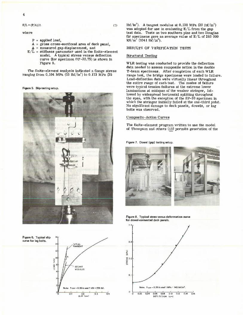
tion, i.e., the slip modulus, was evaluated by using the special laboratory device s hown in Figure 5, which was similar to one used by McLain (18). By the use of this device, specimens comprised ofa small piece of deck panel and bridge stringer fastened together by a single lag bolt were tested in a single shear configuration. The result of each test is a slip curve, such as that shown in Figure 6. As an approximation to the nonlinear slip curve, a secant at the 0.25-mm (0.010-in) slip level was adopted for use in the analytical work. Because the actual slip recorded during WLR testing of the double T-beam specimens ranged up to 0.13 mm (0.005 in), this secant is a conservative choice. Two slip spec imens wer e made for each stringer; the average values of slip modulus obtained were 8.23 MN/m (47 000 lbf/in) and ·8.060 MN/m (46 000 lb.f/in) for southern pine and Douglas fir respectively. The over all average for both species combined was 8.200 .MN/m (46 800 lbf/ in).
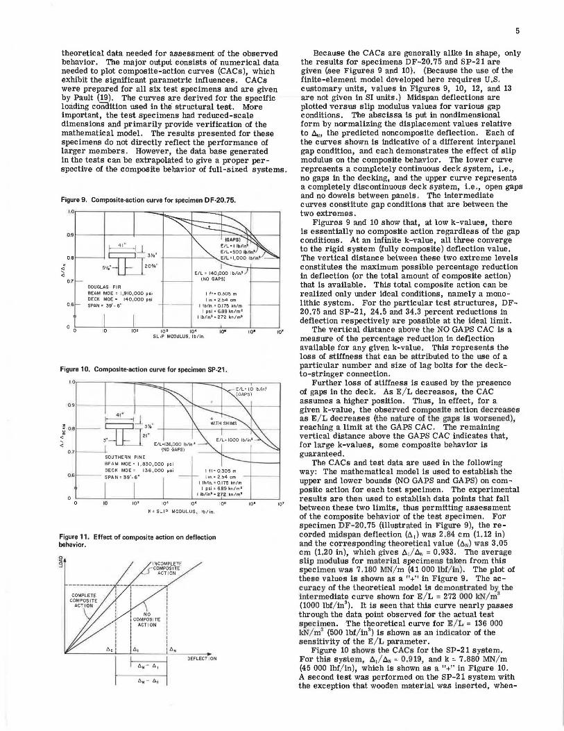
Quantification of the axial stiffness of the dowel connection used between adjacent deck panels is necessary for proper modeling of the joint in the finite-element analysis. To accomplish this, the load frame used in the T-beam tests was adapted as shown in Figure 7 to permit axial tests of the deck material. Test panels were cut to 0.61-m widths to facilitate handling and satisfy the clearance constraint of the framework. Dowel holes were oversize by 0. 79 mm (1/J2 in) and lubricated before assembly (as done in the structural tests). A WB x 15 steel beam was grouted on top of the specimen to distribute the applied loads. Six LVDTs recorded the deformations across the dowel joint to provide the data needed for plotting load versus deflection curves. Conversion to stress versus deflec -tion data permits computation of the axial stiffness according to
Figure 3. Loading apparatus.
r= 20 3cm
LOAD CELL RECEPTICLE VARIABLE NUMBER OF STEEL SHIMS
Nate : 1 m = 39.4 in.
Figure 4. Slip instrumentation.
4
E/L = (P/A)//::; (2)
where
p A b.
E/L =
applied load, gross cross-sectional area of deck panel, measured gap displacement, and stiffness parameter used in the finite-element model. A typical stress versus deflection curve (for specimen DF-20. 75) is shown in Figure 8.
The finite-element analysis indicated a flange stress ranging from 0.104 MPa (15 lbf/in2
) to 0.173 MPa (25
Figure 5. Slip-testing setup.
Figure 6. Typical slip 16
curve for lag bolts. 14 -
12
10
8
INITIAL TAM~NT
Note: 1 cm= 0.39 in and 1 kN = 225 lbf.
· 001?----'----,o,.,., ~, --'--o'"'".z--'--~o ...... l_.__....,,.o 4 SLIP (cml
lbf/in2). A tangent modulus at 0.138 MPa (20 lbf/in2
)
was adopted for use in evaluating E/L from the gap test data. Tests on two southern pine and two Douglas fir specimens gave an average value of E/L of 283 000 kN/m3 (1041 lbf/in3
).
RESULTS OF VERIFICATION TESTS
structural Testing
WLR testing was conducted to provide the deflection data needed to assess composite action in the double T-beam specimens. After completion of each WLR range test, the bridge specimens were loaded to failure. Load-deflection data were virtually linear throughout the entire range of each test. The modes of failure were typical tension failures at the extreme lower laminations at midspan of the weaker stringer, followed by widespread horizontal splitting throughout the span, with the exception of the SP-30 specimen in which the stringer initially failed at the one-third point. No significant damage to deck panels, dowels, or lag bolts was observed.
Composite-Action Curves
The finite-element program written to use the model of Thompson and others (13) permits generation of the
Figure 7. Dowel (gap) testing setup.
Figure 8. Typical stress versus deformation curve for dowel-connected deck panels.
0.3
D
! ~02 w "' ti;
0 . 1
Note: 1 cm= 0.39 in and 1 MPa = 145 lbf/in2 .
0 0 002 0.04 006 008 0.10 012 0 .14 016
DEFLECTION lcml
theoretical data needed for assessment of the observed behavior. The major output consists of numerical data needed to plot composite-action curves (CACs), which exhibit the significant parametric influences. CACs were prepared for all six test specimens and are given by Pault (19). The curves are derived for the specific loading condition used in the structural test. More important, the test specimens had reduced-scale dimensions and primarily provide verification of the mathematical model. The results presented for these specimens do not directly reflect the performance of larger members. However, the data base generated in the tests can be extrapolated to give a proper perspective of the composite behavior of full-sized systems.
Figure 9. Composite-action curve for specimen DF-20.75.
1.or---.----,--...;::r---r- ===---,,-----,
07
06
DOUGLAS· Fl R
BEAM MOE• 1,910,000 poi DECK MOE• 140,000 psi SPAN • 39' - 6"
E/L • 140,000 lb/in.' (NO GAPS)
I 11= 0305 m
I in. "' 2..54 cm I lb/in "'0 175 kn/m
I psi• 6.89 kn/m 2
I lb/ins• 272 kn/ma
0 o~--~10-----:':10~.--~10~,,..---1~0,,.----'-10~•--~10~•---'10• SLIP MOOULUS, lb/in.
Figure 10. Composite-action curve for specimen SP-21.
~-iJ ~~ !LB Cfl=l]2:~•" <l
3l~" --l_J=._ E/L=l36,000 lb/Ins 0.71---- (NO GAPS)
0.6
0 0
SOUTHERN PINE
BEAM MOE• 1,830,000 psi DECK MOE • 136,000 psi
SPAN• 39'-6"
10 101 10• 10•
I fl=0,305 m
tin"' 2 54 cm I lb/in.= 0.175 im/m
I ps i = 6 .89 kn/m 2
I lb/in~"' 272 kn/m 1
10•
K =SLIP MODULUS , lb/in
Figure 11 . Effect of composite action on deflection behavior.
10• 10•
5
Because the CACs are generally alike in shape, only the results for specimens DF-20. 75 and SP-21 are given (see Figures 9 and 10). (Because the use of the finite-element model developed here requires U.S. customary units, values in Figures 9, 10, 12, and 13 are not given in SI units.) Midspan deflections are plotted versus slip modulus values for various gap conditions. The abscissa is put in nondimensional form by normalizing the displacement values relative to ~. the predicted noncomposite deflection. Each of the curves shown is indicative of a different interpanel gap condition, and each demonstrates the effect of slip modulus on the composite behavior. The lower curve represents a completely continuous deck system, i.e., no gaps in the decking, and the upper curve represents a completely discontinuous deck system, i.e., open gaps and no dowels between panels. The intermediate curves constitute gap conditions that are between the two extremes.
Figures 9 and 10 show that, at low k-values, there is essentially no composite action regardless of the gap conditions. At an infinite k-value, all three converge to the rigid system (fully composite) deflection value. The vertical distance between these two extreme levels constitutes the maximum possible percentage reduction in deflection (or the total amount of composite action) that is available. This total composite action can be realized only under ideal conditions, namely a monolithic system. For the particular test structures, DF-20.75 and SP-21, 24.5 and 34 .3 percent reductions in deflection respectively are possible at the ideal limit.
The vertical distance above the NO GAPS CAC is a measure of the percentage reduction in deflection available for any given k-value. This represents the loss of stiffness that can be attributed to the use of a particular number and size of lag bolts for the deckto-stringer connection.
Further loss of stiffness is caused by the presence of gaps in the deck. As E/L decreases, the CAC assumes a higher position. Thus, in effect, for a given k-value, the observed composite action decreases as E/ L decreases (the natw·e of the gaps is worsened), reaching a limit at the GAPS CAC. The remaining vertical distance above the GAPS CAC indicates that, for large k-values, some composite behavior is guaranteed.
The CACs and test data are used in the following way: The mathematical model is used to establish the upper and lower bounds (NO GAPS and GAPS) on composite action for each test specimen. The experimental results are then used to establish data points that fall between these two limits, thus permitting assessment of the composite behavior of the test specimen. For specimen DF-20.75 (illustrated in Figure 9), the recorded midspan deflection (6 1) was 2.84 cm (1.12 in) and the corresponding theoretical value (6N) was 3.05 cm (1.20 in), which gives 6 1/ .6N = 0.933. The average slip modulus for mater ial specimens taken from this specimen was 7 .180 MN/m (41 000 lbf/ in). The plot of these values is shown as a "+" in Figure 9. The accuracy of the theoretical model is demonstrated by the inter mediate curve shown for E/ L = 272 000 kN/ m3
(1000 lbf/ in3). It is seen that this curve nearly passes
through the data point observed for the actual test specimen. The theoretical curve for E/ L = 136 000 kN/ m3 (500 lbf/ in3
) is shown as an indicator of the sensitivity of the E/ L parameter .
Figure 10 shows the CACs for the SP-21 system. For this system, 6./ .6N = 0. 919, and k = 7 .880 MN/ m (45 000 lbf/in), which is shown as a "+" in Figure 10. A second test was performed on the SP-21 system with the exception that wooden material was inserted, when-
6
Figure 12. Composite-action curve for extrapolated specimen DF-20.75.
08
. ~ 07 <l
06
DOUGLAS FIR BEAM MOE" 1,914,000 psi DECK MOE ,. 140,000 psi SPAN• 39'· 6" I fl "0305m
I in .. 2 54cm 05, 1--->--~--~--f.-1 lb/in =0. 175 kn / m
I ps i• 6 89 kn/ml
0 0 10 10 • '° 10• 10 1
SLIP MODULUS, I b/in 10' IO'
Figure 13. Composite-action curve for full-scale bridge that has a 12.2-m (40-ft) span.
1 ,0r---,...---~---.--===--,-----,..--=:::-y-------,
oe
06 . ~ <l
04
02
0 0 10
BEAM MOE• 1,900,000 psi DECK MOE= 140,000 ps i BEAM MOE• 1,900,000 psi DECK MOE• 1,900,000 psi SPAN 39 1- 6 11
102 10• 104
I fl sQ305 m
I in:s2 54cm I lb/in • 0 I 75 kn/m
I psi " 6 89 kn/m2
10 1
SL IP MODULUS, lb/ in
... __
10'
ever possible, in the gaps within the deck layer. This test gave a lower D. 1-value and, consequently, lowered the abscissa (6/ 6i;) to a value of 0.849 (in Figure 10, this is the curve identified as "+WITH SHIMS") . The decrease in deflection is emphasized by noting the position of the t wo data points relative to the gapapf,roximation curve, E/ L = 272 000 kN/ rn" (1000 lbf/ in ). This procedure was repeated for the SP-30 system and led to similar results. The results are significant and serve to illustrate the variability and effect of the gap condition on overall performance .
Numerical Results
Figure 11 schematically illustrates the general load versus deflection curves for the two extremes of composite behavior and for the incomplete composite behavior that is typical of laye1·ed systems. The maximum percentage composite actfon available (CAA) is that realized by the monolithic system and is given by
10'
(3)
where
.:iN = theoretical deflection of system if behavior is not composite and
A, = theoretical deflection of system if behavior is completely composite.
The efficiency (EFF) exhibited by the actual layered
system (the percentage of the CAA that is achieved) is given by
(4)
where 6 1 =the measured deflection. The percentage of the composite action observed (CAO) in the real sys~ tern is given by
CAO = EFF x CAA (5)
For specimen SP-21, the values computed for 6N and 6 0 were 2.62 cm (1.03 in) and 1.72 cm (0.677 in) respectively. In the structural test, 6 1 was recorded as 2.41 cm (0.947 in). These values imply 34.3 percent CAA, 23.5 percent EFF, and 8.1 percent CAO for the specimen. In the second test, that with shimmed gaps, 6 1 was recorded as 2.22 cm (0.874 in). CAA, of course, is unchanged, but EFF is increased to 44.2 percent, thus increasing CAO to 15.2 percent.
The experimental results for the siJC test specimens are given below (1 MPa = 145 lbf/ in2
) ; most of the MOE values listed are the average value for the two stringers.
Working-Load Range
MOE CAA EFF CAO Specimen (MPa) (%) (%) (%)
SP-21 With shims 12 630 34.3 23.5 8.1 Without shims 12 630 34.3 44.2 15.2
SP-25.5 11 730 21 .0 35.9 7.5 SP-30
With shims 12 970 17.6 19.3 3.4 Without shims 12 970 17.6 37.6 6.6
DF-25.5 (west 14 700 26.7 27.0 7.2 stringer only)
DF-20.75 13180 24.5 27.2 6.7 DF-30 13 460 17.2 45.0 7.7
The t heoretical and experimental results for the test specimens are given below (1 N = 0.225 lbf); the load values, Pat failure, listed are the loads applied to the girder by the spreader beam reaction (as observed in the actual, laboratory, failure-load tests).
Theoret· Failure ical
Specimen p (N) MOR (MPa) am (MPa)
SP-21 25.1 37.7 34.5 SP-25.5 71.2 43.4 41.4 SP-30 110.0 47 .6 47.4 DF-25.5 45.8 44.5 42.6 DF-20.75 42.3 38.0 36.1 DF-30 107 .0 46.0 44 .2
The CAAs ranged between 17.6 and 34.3 percent and between 17 .2 and 26. 7 percent for the southern pine and Douglas fir species respectively. The last two columns compare the observed modulus of rupture (MOR) based on the section modulus of the stringer alone with the theoretical outer-fiber tensile stress at the failure load as predicted by the mathematical model.
OBSERVATIONS FROM TEST PROGRAM RESULTS
The CACs show that four key variables have significant effects on the system performance. These are (a) the type and nature of the gaps (i.e., the gap effect) in the deck layer that is characterized by the axial stiffness E / L, (b) the interlayer connectivity achieved by the lag

bolts as characterized by the slip modulus, (c) the size of the deck panels, and (d) the deck panel MOE value.
The thinner deck used in the reduced-scale system is felt to be the primary cause of the large gap effect observed in the reduced-scale tests. The thickness of the deck gave rise to construction difficulties in panel alignment caused by warping (a problem not encountered in normal size deck panels). The gaps were not fully butted in most cases and, thus, the continuity was interrupted to a larger degree than expected in thicker decks.
The slip modulus is a function of the size and number of lag bolts provided for each deck panel. The degree of connection of the deck and girders can be improved by increasing the number of lag bolts or, as shovm by Van Dyer (20), by changing the size of the connectors. Full-sized bridge systems gene1·ally have higher slip moduli than the reduced-scale system because of the larger bolts used and the effect of thicker deck panels.
IMPLICATIONS FOR FULL-SIZE SYSTEMS
The deficiencies of the reduced-scale test specimens were discussed above. By extrapolating the deck dimensions to full-sized cross sections and generating the CA Cs of 'these sections valuable comparisons are possible. This was done for all six test specimens; complete results are given by Pault (19). To illustrate this the CAC for the extrapolated DF-20.75 section is giv~n in Figure 12, in which the stringer size, span, and loads are identical to the test-specimen values, but the deck thickness and effective width have been increased to dimensions more practical for the stringer size (1). When compared with the test specimen, the CAA has increased from 24.5 to 37.3 percent. The average increase in the CAA for all six specimens, as reported by Pault (19), was 14 percent.
Perhaps the characteristic most detrimental to composite behavior in the glulam bridge system is ~he d~ck MOE. Figure 13 emphatically demonstrates this pomt. The solid curves show the limits of composite behavior possible for the existing system, i.e., a deck MOE of 966 MPa (140 000 lbf/ in2
); the dashed curves are the limits corresponding to an identical system except that the deck MOE is 13 100 MPa (1 900 000 lbf/in2
), i.e., the longitudinal MOE value. At the ideal limits, a 68 percent reduction in deflection is possible. Even at practical k-values, conceptual innovations to better orient deck panels can result in greatly improved composite behavior.
CONCLUSION
An experimental and analytical investigation of the composite behavior in glulam bridge systems was successful. Composite action was predicted for a range of reducedscale test specimens. Although this action was relatively low in the test specimens, the levels observed do not directly reflect the much greater degree of interac -tion available in actual bridges. A mathematical model was used to extrapolate the work and permit a study of full-sized systems. These extrapolations indicate that composite design can result in significant reduction in deflection as compared with current design procedures that neglect component interactions. Design improvements, particularly in the decking, could lead to even greater increases in stiffness.
ACKNOWLEDGMENTS
We gratefully acknowledge the support given this project by the Engineering Foundation, the principal sponsor.
7
Material support and continuous input was given by the American Institute of Timber Construction. Several undergraduate students had significant involvement in the construction, testing, and data-reduction phases; we express appreciation for their energetic efforts.
REFERENCES
1. Glulam Bridge Systems. Plans and Details. American Institute of Timber Construction, Englewood, CO, 1974.
2. Modern Timber Highway Bridges. A State-of-theArt Report. American Institute of Timber Construction, Englewood, CO., July 1973.
3. L. G. Clark. Deflections of Laminated Beams. Trans., ASCE, Vol. 119, 1954, pp. 721-736.
4. H. Granholm. Om Sammansatta Balkar Och Pelare Med Sarkilo Hansyn Till Sapikade Trakonstrakioner. Chalmers Tekniska Hogskoas Handlinger, No. 88, 1949.
5. P. F. Pleshkov. Teoria Rashceta Depeviannykh. Moscow, 1952.
6. N. M. Newmark, C. P. Seiss, and I. M. Viest. Tests and Analysis of Composite Beams With Incomplete Interaction. Proc., Society of Experimental Stress Analysis, Vol. 19, No. 1, 1951.
7. C. P. Seiss, I. M. Viest, and N. M. Newmark. Small-Scale Tests of Shear Connectors of Composite T-Beams. Univ. of Illinois Experimental station, Bull. 396, Vol. 49, No. 45, Feb. 1952.
8. C. B. Norris, W. S. Erickson, and W. J. Kommers. Flexural Rigidity of a Rectangular Strip of Sandwich Construction-Comparison Between Mathematical Analysis and Results of Tests. Forest Products Laboratory, Madison, WI, Rept. 1505A, May 1952.
9. E. W. Kuenzi and T. L. Wilkinson. Composite Beams-Effect of Adhesive on Fastener Rigidity. Forest Service, U.S. Department of Agriculture, Res. Paper FPL 152, 1971.
10. J. R. Goodman. Layered Wood Systems With Interlayer Slip. Univ. of California, Berkeley, PhD thesis, 1967.
11. J. R. Goodman. Layered Wood Systems With Interlayer Slip. Wood Science, Vol. 1, No. 3, 1969.
12. J. R. Goodman and E. P. Popov. Layered Beam Systems With Interlayer Slip. Journal of the Structural Division, Proc., ASCE, Vol. 94, No. ST 11, Nov. 1968.
13. E. G. Thompson, J. R. Goodman, and M. C. Vanderbilt. Finite-Element Analysis of Layered Wood Systems. Journal of the Structural Division, Proc., ASCE, Vol. 101, No. ST 12, Dec. 1975, pp. 2659-2672.
14. M. L. Kuo. Verification of a Mathematical Model for Layered T-Beams. Colorado state Univ., Ft. Collins, MS thesis, 1974.
15. G. A. Tremblay. Nonlinear Analysis of Layered T-Beams With Interlayer Slip. Colorado State Univ., Ft. Collins, MS thesis, 1974.
16. M. D. Vanderbilt, J. R. Goodman, and M. E. Criswell. Service and Overload Behavior of Wood Joist Floor Systems. Journal of the Structural Division, Proc., ASCE, Vol. 100, No. ST 1, Jan. 1974, pp. 11-30.
17. J. Bodig and J. R. Goodman. Prediction of the Elastic Parameters for Wood. Wood Science, Vol. 5, No. 4, April 1973.
18. T. E. McLain. Curvilinear Load-Slip Relations in Laterally-Loaded Nailed Joints. Colorado State Univ., Ft. Collins, MS thesis, 1975.
8
19. J. D. Pault. Composite Action in Glulam Timber Bridge Systems. Colorado State Univ., Ft. Collins, MS thesis, 1977.
20. D. B. Van Dyer. strength of Built-Up Timber
Columns. Nova Scotia Technical College, Halifax, PhD thesis, 1976.
Publication of this paper sponsored by Committee on General Structures.
Some Examples of Detection and Repair of Fatigue Damage in Railway Bridge Members R. A. P. Sweeney, CN Rail, Montreal
Examples of details that have caused fatigue damage in recently designed railway structures are given. Procedures for arresting crack growth and some repair details are described. Emphasis is placed on damage caused by secondary and out-of-plane effects often not considered by designers.
This paper is concerned with some details that have caused fatigue damage in recently designed railway structures and that may not be generally recognized as inadequate by the design profession.
Sufficient experience had been gained by World War I to determine the adequacy of various riveted details. In general, any fatigue problems on riveted structures experienced on our railroad are caused by extremely high cycle fatigue, overloading, or details that are well known to be inadequate. Detailing of riveted railway bridge construction has not changed appreciably during the last 40 years. This, together with the greater concern for the teaching of overall analysis brought about by the digital computer, has led to a generation of engineers unconcerned with details. In many cases, major details are left to the discretion of the draftsperson.
Unfortunately, welded structures tend to be less forgiving of small defects than are riveted structures because they normally contain less excess material and because the welds themselves are points of rigidity and residual stress. Details that had been proved over many years of experience to be adequate for riveted structures arc proving to be inadequate for welded st1~uctu1·e:s. In particular, much greater attention must be paid to outof-plane stresses and secondary effects.
It is only within the last few yeus that, as a result of some failures (1), new research and the study of fracture roechanicfl l; :'!) hf!vA pP.rmittP.d including in the codes more detailed advice on the suitability and limitations of various welded details .
On our railway, the change from riveted to welded designs took place in the early 1960s. The first designs incorporated details patterned after existing riveted construction.
DETAILS
1. As an extreme example and to make a point, consider the multibeam structure shown in Figure 1. The cover plates are attached by intermittent welds. Each small length of weld is designed to replace a cer-
tain number of rivets. The current codes classify this as an E-detail because of the lack of adequate test data. Nevertheless, in this case, it is probable that higher strength exists because the intermittent welds are continuing so that the connected plates are about equally strained and because the welds are well made. This last point is crucial in evaluating details. Despite the fact that the structure has been in service since 1961, because of its redundancy, the actual average rootmean-square stress range is far below the limits of category E. Unfortunately, defective details take time to become evident and, because of redundancy, may never show up.
2. On our railway, the first group of problems to develop on welded structures were cracks at the bottoms of stiffeners on skewed structures. Figure 2 shows a typical example-a diaphragm or brace frame attached to a stiffener in which the stiffeners are not extended to the bottom flange. This was in blind obedience to the dictum of an early worker in welded construction that one should not weld to the tension flange. Because of the stresses introduced by the differential deflections of the connected girders and by small out-of-plane movements, cracks appeared in less than 5 years on heavily traveled lines. This type of crack begins at the bottom of the stiffener and then forms a "U" shape around it. If the original stiffener-web weld is of good quality, the crack turns out into the web and slows considerably. A temporary cure is to driii a round hoie containing the crack tip. However, if the web-stiffener weld has a series of surface toe discontinuities (undercut or lack of penetration), the crack can run up the web, which causes the girder to split in half. Fortunately, our railway has not experi&nc&d such a. fa.Huro. Figure 3 shows a crack following a weld upward. A circular hole was drilled to prevent any further propagation.
3. After cracks have occurred as described above, the next point of rigidity is that between the web and flange. If there is any motion out of the plane of the girder, it is only a matter of time before there will be cracks in the web-to-flange weld below the stiffener (Figure 4). Stopping these cracks is very important. Figure 5 summarizes the problems with this type of cracking.
4. Similar cracks have also occurred on a few nonskewed structures at the C-detail at the bottom of the stiffener simply because the stress range was too high.


![Change Mgt 676[1]](https://img.pdfslide.us/doc/110x75/577d1e141a28ab4e1e8db1e6/change-mgt-6761.jpg)


![One Piece 676 [manga-worldjap.com]](https://img.pdfslide.us/doc/110x75/568bd7851a28ab2034a005fb/one-piece-676-manga-worldjapcom.jpg)