Embed Size (px)
Citation preview

Instruction manual en
testo 6740

Preface 2
Preface Preface
Dear Testo Customer
Congratulations for choosing a Testo product. We hope that you will enjoy many years of using the product and that it will help you in your work.
If problems should occur which you cannot rectify yourself, please consult our service department or your dealer. We will endeavour to provide fast and competent assistance to save you long periods out of operation.

General information 3
General informationThis Instruction manual contains important information about the features and use of the product. Please read this document through carefully and familiarise yourself with the operation of the product before putting it to use. Keep the Instruction manual to hand so that you can refer to it when necessary.
Pictograms
This product could be dangerous if operated incorrectly. Information that requires particular attention is identified in this Instruction manual by pictograms:
Warnings are identified by means of a warning triangle. The relevant signal word! indicates the degree of risk:
Warning! means: Serious physical injury could occur if you do not take the precautionary measures indicated.
Caution! means: Slight physical injury or material damage could occur if you do not take the precautionary measures indicated.
Pay particular attention to warnings and take the precautionary measures indicated in order to avoid danger.
Notes on special cases and peculiarities in the handling of the product are indicated by an exclamation mark.
Standards/Approvals
According to the conformity certificate, this product fulfills all2004/108/EEC guidelines.
Signal word!

Contents4
Contents Preface ..................................................................... 2
General information .................................................. 3
Contents ................................................................... 4
1. Basic safety information ........................................... 5
2. Intended use ............................................................ 6
3. Product description .................................................. 73.1 System components ................................................ 73.2 Operating elements ................................................. 73.3 Settings ................................................................... 83.4 Current output intervals ............................................ 8
4. Initial operation .......................................................... 94.1 Mechanical assembly .............................................. 94.2 Electric connection ............................................... 114.3 Analog output / Limit signal outputs ....................... 14
5. Menu guide (0555.6743 / 0555.6744 only) .............. 16
6. Adjustment on site .................................................. 19
7. Care and maintenance ............................................ 23
8. Troubleshooting ...................................................... 24
9. Technical data ....................................................... 259.1 Measurement ranges and accuracies .................... 259.2 Additional instrument data ..................................... 259.3 Uncertainty pressure dewpoint temperature ........... 26
10. Accessories / Spare parts ....................................... 27

1. Basic safety information 5
1. Basic safety informationAvoid electrical hazards:
Never take measurements with the instrument and its probes on or near live components unless the instrument is expressly approved for current and voltage measurements.
Protect the instrument:
Never store the unit together with solvents (e.g. acetone).
Preserving product safety/warranty entitlement:
Operate the instrument only within the parameters specified in the Technical data.
Handle the instrument appropriately and according to its intended purpose.
Never apply force!
Temperature data on sensors/probes refer only to the measurement range of the sensors. Do not subject handles and lines to temperatures greater than 70°C if they are not expressly approved for higher temperatures.
Open the instrument for maintenance and repair purposes only if specifically described in the Instruction Manual.
Maintenance work should only be carried out if described in the Instruction Manual. Please adhere to the steps described. For safety reasons, please only use spare parts from Testo.
Any additional work should only be carried out by authorised trained personnel. Otherwise Testo does not accept responsibility for the functioning of the instrument following maintenance and for the validity of approvals.
Dispose of carefully:
Once its service life has come to an end, return the instrument to us and we will dispose of it.

2. Intended use6
2. Intended useThe instrument is intended for use in the following applications:
The testo 6740 instrument is a pressure dew point transmitter for measuring trace humidity. It is used in the following areas:- Monitoring trace humidity in compressed air systems and gas networks
(e.g. pipeline and container drying).- Controlling and monitoring (compressed air) driers.- Monitoring compressed air humidity in vehicles.- Monitoring humidity and temperature in medical compressed air or
granulate driers.
Application in hazardons areas is not allowed!

3. Product description3.1 System components
7
3. Product description3.1 System components
3.2 Operating elementsThe instruments with the article numbers 0555.6741 and 0555.6742 do not have any additional operating elements.
The instruments with the article numbers 0555.6743 and 0555.6744 have a keypad and a display to input and read off settings (See 5. Menu guide, p. 16).
All of the instruments of Type testo 6740 can be parameterised with the aid of the 0554.3305 scaling adapter.
G½, without display0555.6741
NPT½“, without display0555.6742
G½, with display0555.6743
NPT½“, with display0555.6744
Standard plug, 4 to 20mA (included with all instruments)Accessories:0554.3302 plug (4 to 20mA, 2 switch contacts, 2 LEDs)
1 Only required for process temperatures > 50°C, cooling coil only in connection with measurement chamber
2 Measurement chamber only required if
- incoming flow is to be increased (measurement chamber guarantees a minimum incoming flow of 1l/min at a positive pressure of 6bar).
- fast assembly/dismantling of transmitter without interrupting process is required.
To process
Cooling coil 10554.3304
Measurement chamber 20554.3303
To PLC/control/analysis unit
Standard quick-release device G½ thread
Max. pressure: 15barabs
Max. pressure: 50barabs

3.3 SettingsThe parameters in the instrument are assigned the following values in the factory (default values):
3. Product description3.3 Settings
8
Parameter Pressure dew point 1 Atmospheric dew point 1 Relative humidity Temperature Absolute humidity
Unit °Ctp °Ftp °CtA °FtA %rF, %rh, %Hr °C °F ppmv mg/m3 (Abs)4mA -60 -75 -60 -75 0 0 32 0 020mA 30 85 30 85 100 50 120 30000 2 30000 2
LS 4 40 4 40 30 10 50 8400 7000US 10 55 10 55 50 30 85 13000 9600Hyst 2 2 2 2 2 2 2 2 2
1 With dew point temperatures <0°Ctp / <0°CtA / <32°Ftp / <32°FtA the frostpoint temperature (dewpoint upon ice) is displayed
2 Display is shown to the power of ten: 30E3 (corresponds to 30 x 103 = 30 x 1000 = 30000)
3.4 Current output intervals
Failure information AMeasurement information M Failure information A
4. Initial operation4.1 Mechanical assembly
9
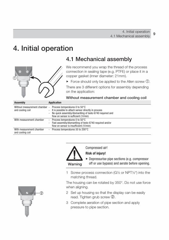
4.1 Mechanical assemblyWe recommend you wrap the thread of the process connection in sealing tape (e.g. PTFE) or place it in a copper gasket (inner diameter: 21mm).
Force should only be applied to the Allen screw .
There are 3 different options for assembly depending on the application:
Without measurement chamber and cooling coil
Compressed air!
Risk of injury!
Depressurise pipe sections (e.g. compressor off or use bypass) and aerate before opening.
1 Screw process connection (G½ or NPT½“) into the matching thread.
The housing can be rotated by 350°. Do not use force when aligning.
2 Set up housing so that the display can be easily read. Tighten grub screw .
3 Complete aeration of pipe section and apply pressure to pipe section.
4. Initial operation
Assembly Application
Without measurement chamber - Process temperatures 0 to 50°Cand cooling coil - It is possible to attach sensor directly in process - No quick assembly/dismantling of testo 6740 required and flow on sensor is sufficient (1l/min)With measurement chamber - Process temperatures 0 to 50°C - Fast assembly/dismantling of testo 6740 required and/or flow on sensor is insufficient (1l/min)With measurement chamber - Process temperatures 50 to 200°Cand cooling coil
Warning

4. Initial operation4.1 Mechanical assembly
10
With measurement chamber (max. 15bar)
1 Connect measurement chamber without measure-ment transmitter to the compressed air push-in quick connection for approx. 10 - 30 s, in order to blow out any dirt deposits
2 Remove measurement chamber from compressed air push-in quick connection.
3 Screw in process connection (G½) of the testo 6741 / 6743 transmitter in measurement chamber thread.
4 Snap push-in quick connection of measurement chamber in standard socket of compressed air line.
With measurement chamber and cooling coil (max. 15bar)
1 Connect measurement chamber without measure-ment transmitter to the compressed air push-in quick connection for approx. 10 - 30 s, in order to blow out any dirt deposits
2 Remove measurement chamber from compressed air push-in quick connection.
3 Screw in process connection (G½) of testo 6741 / 6743 transmitter into thread of measurement chamber.
4 Snap push-in quick connection of measurement chamber in push-in quick connection of the cooling coil.
5 Snap second push-in quick connection of the cooling coil into the standard socket of the compressed air line.

4. Initial operation4.2 Electric connection
11
4.2 Electric connection Standard plug
We recommend an 8 wire cable with a tightly braided screen and a core cross-section of 0.2 to 0.5mm2.
1 Loosen and remove screw at the back of the plug and remove plug from transmitter .
2 Remove plug socket from the plug housing. To do this apply a small screwdriver to the point marked with “lift“ and press out carefully .
3 Screw on the cable positioning device and guide the cables through the plug housing .
4 Connect cable ends to the screw terminals of the plug socket :Plug socket terminals
1: + (4 to 20mA), power: 12...30VDC 2: - (4 to 20mA)3: Not assigned4: Measuring earth (cable screen)
5 Insert plug socket into plug housing again until it snaps into place and screw on cable fixing unit.
6 Attach plug to transmitter and secure with screw .

4. Initial operation4.2 Electric connection
12
Relay board terminals
1: 20 to 28 VDC 2: LS + 3: LS - 4: US + 5: US - 6: 0 VDC
Plug socket terminals
1: I + (4 to 20mA) 2: I - (4 to 20mA) 3: (connected to relay board in factory)
: Put on screen
Current signal and supply 20 to 28 VDC
1
2
3
4
5
6
I +
Flexible lead of relay board
Screen on PE
I -
1
32
Plug socket
Rel
ay b
oard
The supply lines need to be galvanically connected, so connect either - or - !
0554.3302 plug (with 2 switch outputs)
We recommend an 8 wire cable with a tightly braided screen, wire cross-section 0.2 to 0.8mm2.
1 Loosen and remove screw at the back of the plug and remove plug from transmitter .
2 Tilt the cover of the plug housing at an angle and remove .
3 Remove plug socket from the front and the relay board from the back out of the plug housing.
4 Screw on cable positioning device and guide cables through the plug housing.
5 Connect cable ends to the screw terminals of the relay board or the plug socket :

4. Initial operation4.2 Electric connection
13
6 Push plug socket and plug board into the plug housing (pay attention to alignment) and close lid.
7 Screw on cable positioning device.
8 Attach plug to transmitter and screw into place .

4. Initial operation4.3 Analog output / Limit signal outputs
14
4.3 Analog output / Limit signal outputs
Standard plug/ 0554.3302 plug
Both plug variations have a 4 to 20mA analog output available in two-wire technology.
x,y connection:
Connection
x Terminal 1 y Terminal 2
RL
x
y PowerStandard plug:U = 12 to 30V DC0554.3302 plug:U = 20 to 28VDC
Max. load RL (external load):
U Standard 0554.3302
12V 50 Ohm -24V 650 Ohm 650 Ohm30V 950 Ohm -
4 to 20mA
4. Initial operation4.3 Analog output / Limit signal outputs
15
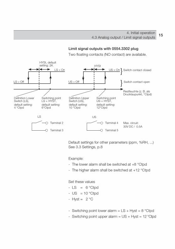
Limit signal outputs with 0554.3302 plug
Two floating contacts (NO contact) are available.
LS = On
LS = Off
US = On
US = Off
Switch contact closed
Switch contact open
Restfeuchte (z. B. als Drucktaupunkt, °Ctpd)
Definition Lower Switch (LS),default setting: 4 °Ctpd
Definition Upper Switch (US),default setting: 10 °Ctpd
HYSt, default setting: 2K HYSt
}
}
LS
Terminal 2
Terminal 3
US
Terminal 4
Terminal 5
Max. circuit:30V DC / 0.5A
Switching point LS + HYST,default setting: 6°Ctpd
Switching point US + HYST,default setting: 12°Ctpd
Default settings for other parameters (ppm, %RH, ...) See 3.3 Settings, p.8
Example:
- The lower alarm shall be switched at +8 °Ctpd
- The higher alarm shall be switched at +12 °Ctpd
Set these values
- LS = 6 °Ctpd
- US = 10 °Ctpd
- Hyst = 2 °C
- Switching point lower alarm = LS + Hyst = 8 °Ctpd
- Switching point upper alarm = US + Hyst = 12 °Ctpd

16 5. Menu guide
5. Menu guide (0555.6743 / 0555.6744 only)
Set unit (Unit)
Pressure dew point °Ctp / °Ftp, atm. dew point 5 °CtA / °FtA, rel. humidity %rF / %Hr / %rh, absolute humidity mg/m3 (display: abs) 5 / ppmv, tempe ra ture °C, °FSelect with
Set 4mA value(S-Lo) 2
Define lower limit of scale 6
= +1 = Next digit
Set 20mA (S-Hi) 2
Define upper limit of scale 6
= +1 = Next digit
Set delay menu query (Pti)
1s / 3s / 5s / 10sSelect using
De/Activate (dS-1) “display can be switched off”
ON = Display can be switched offOFF = Display cannot be switched offSelect using
De/Activate (dS-2)“Change value/unit”
ON = 6s value, 2s unitOFF = Value continuouslySelect using
Set absolute pressure in bar (PrES) 5
= +1 = Next digit
Test analog output (AtES)
-- = No signal 4 = 4mA12 = 12mA20 = 20mASelect using Activate using
ProG
Display: Min. value (Lo)
Display: Max. value (Hi)
Set code (UCod) 7
= +1 = Next digit
Display mode 1, 2, 11, 13
Reading and unit alternately / Reading continuously (see)
Unit
Return to Unit
Return to ProG
3
Display from (see)
CodE
Enter code 10
4 digit password, default setting: 6810
= +1 = next digit
4
Signs and symbols: Press button briefly.
Keep button pressed for 2s.
Change menu using button specified.
Save input using and change menu
or change menu using without
saving input.

175. Menu guide
Set lower switching point (LS) 6
= +1 = Next digit
Set upper switching point (US) 6
= +1 = Next digit
Set hysteresis value (HYSt)
= +1 = Next digit
Test limit signal outputs (tESt)
-0- = Both operating points off-1- = Lower operating point on-2- = Upper operating point onSelect with Activate with
Reference value > - 60°tpd (rEF) 9
= +1 = Next digit
Carry out reset (rES)
nor = No resetrS = Reset (return to default setting))Select using
ALAr 8 AdJ12 rST
Return to ALAr
Return to AdJReturn to rSt
Return to UNIT
Notes:1 If there are breaks in the input, the system returns automatically to
the display mode after approx. 1min.2 In the case of the units ppm and Abs (mg/m3), values are
displayed/entered to the power of ten. Examples: 15E1 corresponds to 15 x 10 = 150, 02E2 corresponds to 2 x 100 = 200, 21E3 corresponds to 21 x 1000 = 21000
3 Keep button pressed (1s / 3s /5s / 10s, corresponding to setting in , default setting: 5s).
4 Only with deactivated code (can be set in Prog - UCod menu).5 Absolute pressure (can be set in Prog - Pres menu) is included
in the calculation of the ppm value and atmospheric dew point (°CtA / °FtA).
6 For negative values: select “-“ at left digit position.7 To deactivate codes: Enter 0000. Important: Note down the code
at a suitable point, operation is impossible without a valid code.8 Can only be used together with the 0554.3302 plug.9 Menu is only available if one of the following units is set: °Ctp, °Ftp,
%rF, %Hr or %rh (can be set in Unit menu). Also see 6. Adjustment on site, p. 18.
10 General password (always valid): 681011 The displayed reading flashes if the scaling limits are exceeded
(can be set in Menu UNIT - S-Lo or S-Hi).12 Compare chapter 6.13 Display blinks if actual values are below 4mA setting or above
20mA setting.

5. Menu guide18
( 0555.6743 only) supplementavailable from versioin June 2007 on. For older versions an updateof the firmware is necessary
Reference value > - 60°tpd (rEF) 9
= +1 = Next digit
Carry out reset (rES)
nor = No resetrS = Reset (return to default setting))Auswahl mit
AdJ rST
Return to AdJReturn to rSt
Set pressure ratioPr= P1/P2
= +1 = Next digit
2PA 14
Return to 2PA
Return to UNIT
Comments:14 Can only be used in combination with a 2-point adjustment (cf.
chap 6.2)15 In this setting point, P1 and the relative humidity at the pressure
level P1 are alternately displayed. Please wait until the relative humidity has a constant value, and
only then press the SET button.16 In this setting point, P2 and the relative humidity at the pressure
level P2 are alternately displayed. Switch the switchover cock of the adjustment device and then wait
until the relative humidity has a constant value, and only then press the SET button.
Display value P1 15
Display value P2 16

6. Adjustment on site 19
6. Adjustment on siteOne point adjustment by inputting one reference value
Using one point adjustment, you can enter a reference value for a working point (e.g. -40°C tpd) specified by you. In this way you will achieve a minimum target/actual deviation from this working point.
A dew point mirror is ideal as a reference measuring instrument.
The Adj menu in which the reference value is entered is only available if one of the following units is set: °Ctp, °Ftp, %rF, %Hr or %rh (See 5. Menu guide, p. 16, Unit menu, Setting unit).
Reference value inputOptimum precision is achieved at reference value-40 °C tpd. In case low dewpoints (<-25 °C tpd) arerelevant, it is suggested to avoid reference values>-30 °C tpd (else loss of precision).1 Expose reference measuring instrument and
testo 6740 to identical, constant conditions and await adjustment time.
2 Measure reference value and compare with testo 6740 reading.
3 If there are deviations in the values, enter reference value in Adj menu.

6. Adjustment on site20
Two-point adjustment for testo 6743available from versioin June 2007 on. For older versions an update of the firmware is necessary(please adress Testo service)
2-pressure adjustment device (0554 3314)
Adjustment chamber
Switchover cock
Sintered filter
A two-point adjustment can be carried out with the testo 6743 and the 2-pressure adjustment device (). The two-point adjustment serves to adjust the testo 6743 to trace humidity. A reference instrument or humidity generator is not necessary. Depending on the position of the switchover cock () of the 2-pressure adjustment device (), the sensor of the testo 6743 is exposed to two different pressure levels.
In front of the switchover cock () of the 2-pressure adjustment device () is a sintered filter () which prevents dirt particles, rust and oil from entering the adjustment chamber ().
The 2-pressure adjustment device () must be under an absolute pressure of min. 3 bar and max. 16 bar.
The calibration certificate of the 2-pressure adjustment device is obligatorily required for the pressure relationship P1/P2.

6. Adjustment on site 21
Installation
1 Screw instrument testo 6743 (G1/2“process connection) into the adjustment chamber ().
2 Connect 2-pressure adjustment device () to the compressed air pipe with the compressed air fast coupling (diameter 7.2).
The permitted operating pressure is 3-16 bar.
Adjustment
1 Read off process pressure / system pressure P1, e. g. from a manometer, and note value.
The manometer should be installed close to the measurement site.
Take the pressure relationship P1/P2 from the calibration certificate (page 2) based on the process pressure. Linear interpolation (calculation) is possible between the two values.
2 Open menu 2PA (see chapter 5 „Menu guide“). P1 and the relative humidity %rF at the pressure level P1 are alternately displayed.
The measuring instrument testo 6743 requires stable pressure values for the two-pressure-adjustment.
3 Wait until the value is constant and then press the SET button (see chapter 5 „Menu guide“).
P2 and the relative humidity %rF at the pressure level P2 are alternately displayed. P2 stands for the pressure in the adjustment chamber () when the switchover cock is closed ().
4 Close valve (position switchover cock () across the measurement chamber () and wait until the relative humidity displayed has a constant value.
5 When the value is constant, confirm with the SET button (see chapter 5 „Menu guide“).
22 6. Adjustment on site
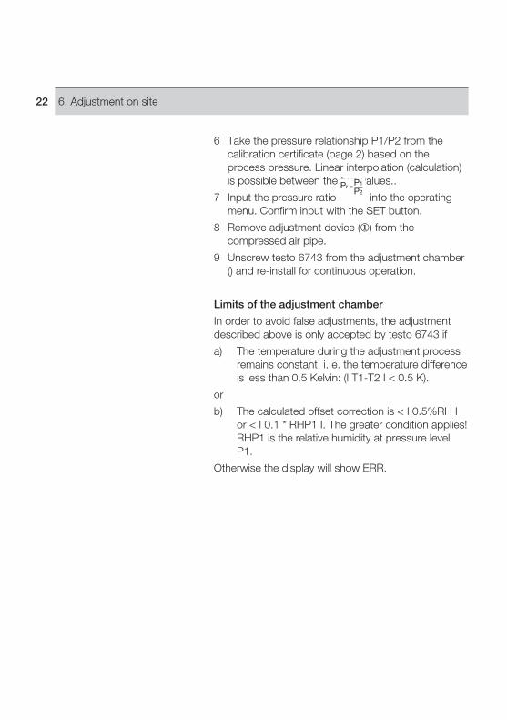
6 Take the pressure relationship P1/P2 from the calibration certificate (page 2) based on the process pressure. Linear interpolation (calculation) is possible between the two values..
7 Input the pressure ratio into the operating menu. Confirm input with the SET button.
8 Remove adjustment device () from the compressed air pipe.
9 Unscrew testo 6743 from the adjustment chamber () and re-install for continuous operation.
Limits of the adjustment chamber
In order to avoid false adjustments, the adjustment described above is only accepted by testo 6743 if
a) The temperature during the adjustment process remains constant, i. e. the temperature difference is less than 0.5 Kelvin: (I T1-T2 I < 0.5 K).
or
b) The calculated offset correction is < I 0.5%RH I or < I 0.1 * RHP1 I. The greater condition applies! RHP1 is the relative humidity at pressure level P1.
Otherwise the display will show ERR.

237. Care and Maintenance
7. Care and MaintenanceFilter, measurement chamber, cooling coil
If process conditions are oily or dusty, the stainless steel sintered filter should be cleaned and also the measurement chamber and cooling coil should be cleaned if used.
Unscrew/remove filter, measurement chamber and cooling coil, purge with compressed air or place in an ultrasonic bath.
Sensor cleaning
During cleaning, avoid touching the sensor at all costs.
Do not clean the sensor mechanically, as this can damage the cover electrode.
Screw off filter cover.
Carefully rinse the sensor with isopropyl alcohol and/or distilled water.
Allow the sensor to dry completely
Cleaning the adjustment chamber
The sintered filter integrated into the adjustment device should be blasted clean with compressed air at regular intervals, depending on the degree of contamination.
Unscrew the sintered filter from the adjustment device and blast clean against the flow-through direction.
After blasting clean, pay attention that the sintered filter is installed in flow-through direction (observe the arrow on the adjustment device, which shows the flow-through direction).
For oily media, the sintered filter, and possibly also the adjustment device, should be cleaned in an ultrasound bath.
After long periods of high humidity, the switchover cock must be opened for drying.

24 8. Troubleshooting
8. TroubleshootingFault Possible causes Remedy
Analog output values - Incorrect scaling or unit Change scaling or unit in Unit menutoo low/too high No signal - Connection interrupted Check cables or - Supply voltage too low Check power: - Polarity incorrect Standard plug min. 12VDC 0554.3302 plug: min. 20VDCSignal >21mA - Sensor defect (broken). Sensor must be replaced. Contact your local distributor or Testo´s Customer Service.Signal <4mA - Sensor corroded Sensor must be replaced. Contact your local distributor or Testo´s Customer Service.Display oF - No signal from sensor Contact your local distributor or Testo´s Customer Service.Displayed reading flashes - Scaling limits exceeded Change scaling limits in Unit - S-Lo or S-Hi Menu
If the fault cannot be repaired by following the suggestions given in the above table, please contact your local distributor or Testo`s Customer service department. For contact data, see back of this document or web page www.testo.com/service-contact

259. Technical data
9.1 Measurement ranges and accuracies
9. Technical data
9.1 Measurement ranges and accuraciesType of mreasurement Measurement range Accuracy
Pressure dew point -45 to +30 °C tpd ±1 K at ±0 °Ctptemperature ±3 K at -20 °C tp (trace humidity) ±4 K at -40 °C tp (at 25 °C)atm. dew point -70 to -15 °C td at 30 barrel cf. pressure dew point temperature -54 to +10 °C td at 3 barrel -45 to +30 °C td at 0 barrelTemperature ±0 to +50°C ±0.5 K
9.2 Additional instrument dataCharacteristic Values
Supply voltage 24 VDC (standard plug: 10 to 30 VDC allowed, 0554.3302 plug: 20 to 28VDC allowed)Max. load 12 V: 100 Ohm, 24 V: 500 Ohm, 30 V: 900 OhmAmbient temperature -20 to +70 °CStorage/transport temperature -40 to +80 °CProtection class IP 65 (with plug attached and cable connected)Rotatability 350°(display alignment) Humidity sensor Testo humidity sensor with logged trace humidity-adjustment at -40 °Ctp / 6 bar Temperature sensor NTCSensor protection Stainless steel sintered capPressure resistance -1 barrel to +50 barabs Measurement chamber 0554.3303: max. 15barabsDimensions 199.5 x 37 x 37 (with standard plug), 203.5 x 37 x 37 (with 0554.3302 plug)Warranty 2 years
Analog output
Signal 4 to 20mA, two-wire technologyScaling Standard: 4 to 20 mA = -60 to +30 °Ctpd, with freely scalable displayOutput parameters °Ctp, °Ftp, °CtA, °FtA, %RH, ppmv, mg/m3, °C, °FResolution 12 bitAccuracy ±40μA
Limit value outputs (optional, only with 0554.3302 plug)
Contacts 2 NO contacts, potential-free, max. circuit 30 V / 0.5 ALower switching point +6°Ctp , with display / scaling adapter freely programmable(LS + HYST)Upper switching point +12°Ctp , with display / scaling adapter freely programmable(US + HYST)

9. Technical data9.3 Uncertainty pressure dewpoint temperature
26
9.3 Uncertainty pressure dewpoint temperature

10. Accessories/Spare parts 27
Name Part no.
Basic instruments (incl. plug for analog signal output)
with process connection G1/2, without display 0555 6741with process connection NPT1/2”, without display 0555 6742with process connection G1/2, with display 0555 6743with process connection NPT1/2”, with display 0555 6744
Accessories
Cable connection plug for power/analog output 4 to 20 mA, with 2 floating switch contacts and 0554 33022 LEDs (limit signal output, alarm output) Measurement chamber for optimum flow on humidity sensor, max. 15 bar, for thread G½ 0554 3303Cooling coil for process temperatures above 50 °C (up to 200 °C) 0554 3304Scaling adapter for testo 6740 0554 3305ISO calibration certificate for pressure dew point (-40° to 0° Ctp at 6 bar), free choice of points 0520 0116ISO calibration certificate for pressure dew point at -10° Ctp and -40° Ctp 0520 0136External display testo 54-2AC, 2 relay outputs (to 300VAC, 3A), 230VAC 5400 7553PTFE hose with compressed air connections, 2m, max. 9bar 0699 2824/4Power unit (desk-top unit), 90 to 264VAC / 24VDC (3A) 0554 1748Power unit (DIN rail mounting), 90 to 264VAC / 24VDC (3A) 0554 1749
10. Accessories / Spare parts

0971 6740 en 09


![Instruction manual [en-US] - Testo · • Only use in accordance with the directions in the instruction manual. • Do not short, ... The testo 310 is a handheld measuring instrument](https://img.pdfslide.us/doc/110x75/5b20730c7f8b9aba568b46c0/instruction-manual-en-us-testo-only-use-in-accordance-with-the-directions.jpg)

![testo 445 · testo 645 Instruction manual en · m/s fpm [ft/min] (testo 445) Factory reset Print parameters hPa mbar psi in W [”H 2O] (testo 445) °C, %, Abs.mbar, rho-g/m3, Pitot](https://img.pdfslide.us/doc/110x75/5fcaa8d7b6565f387c2d2876/testo-445-testo-645-instruction-manual-en-ms-fpm-ftmin-testo-445-factory-reset.jpg)