Embed Size (px)
Citation preview
Testing Telecom Packet Clocks (G.8273)
WSTS 2014, San Jose
Kishan Shenoi CTO, Qulsar, Inc.
Email: [email protected] www.qulsar.com
@qulsar
Presentation Outline
Testing Telecom Packet Clocks Focus on phase/time performance
Protocol not addressed here
Test Principles (G.8273 Annex A)
Testing Configurations (G.8273 Annex B)
Concluding Remarks
(Back-up slides for information)
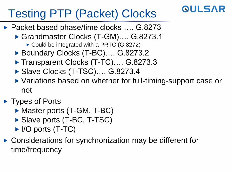
Testing PTP (Packet) Clocks Packet based phase/time clocks …. G.8273
Grandmaster Clocks (T-GM)…. G.8273.1 Could be integrated with a PRTC (G.8272)
Boundary Clocks (T-BC)…. G.8273.2
Transparent Clocks (T-TC)…. G.8273.3
Slave Clocks (T-TSC)…. G.8273.4
Variations based on whether for full-timing-support case or
not
Types of Ports
Master ports (T-GM, T-BC)
Slave ports (T-BC, T-TSC)
I/O ports (T-TC)
Considerations for synchronization may be different for
time/frequency
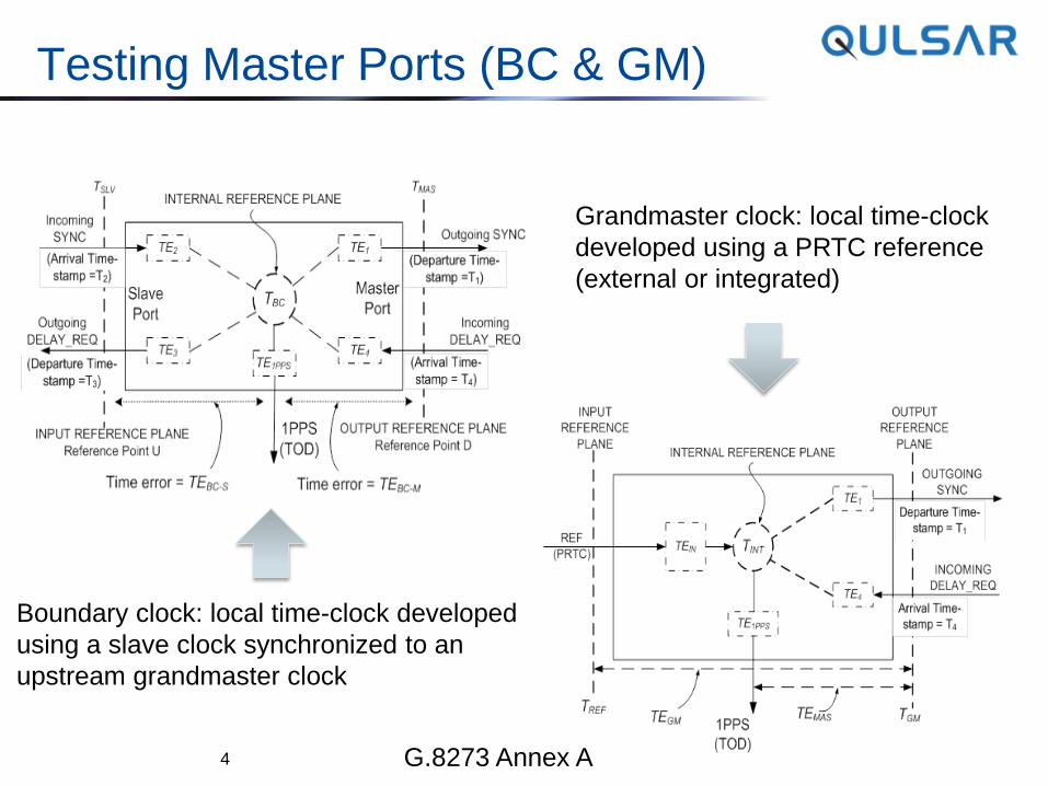
Testing Master Ports (BC & GM)
4
Boundary clock: local time-clock developed
using a slave clock synchronized to an
upstream grandmaster clock
Grandmaster clock: local time-clock
developed using a PRTC reference
(external or integrated)
G.8273 Annex A
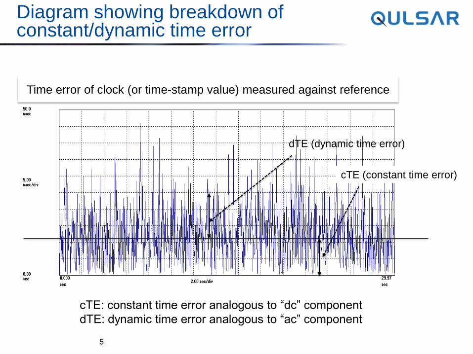
Diagram showing breakdown of constant/dynamic time error
5
Time error of clock (or time-stamp value) measured against reference
cTE (constant time error)
dTE (dynamic time error)
cTE: constant time error analogous to “dc” component
dTE: dynamic time error analogous to “ac” component
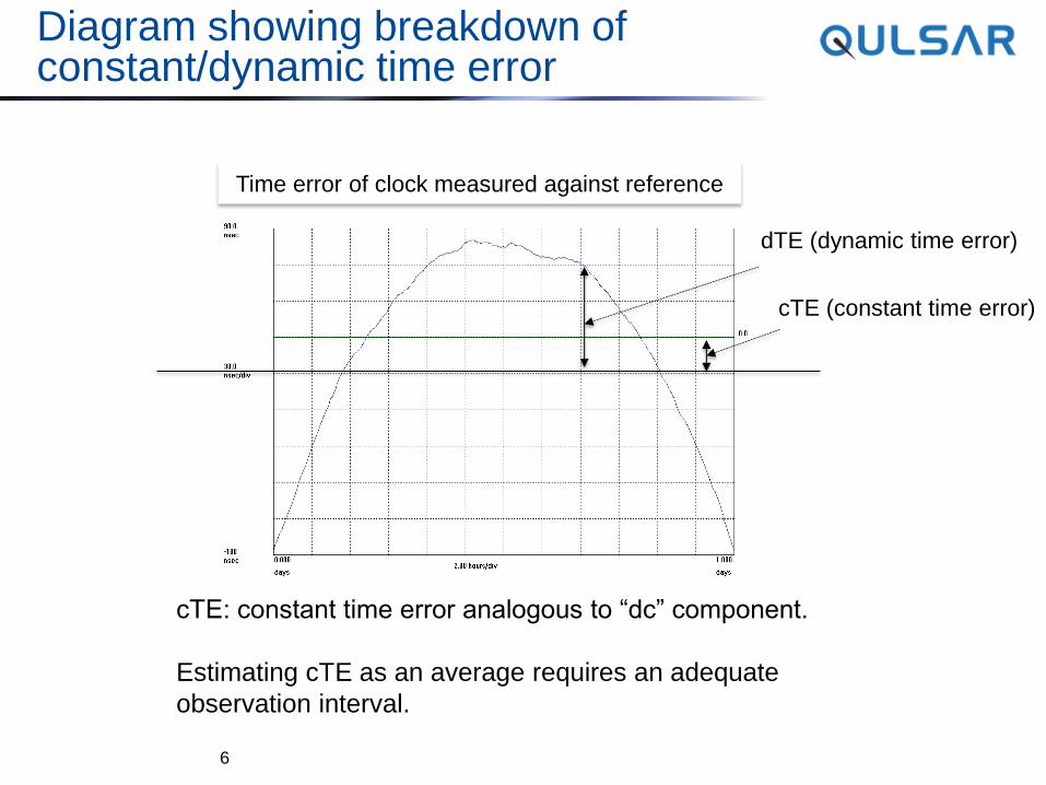
Diagram showing breakdown of constant/dynamic time error
6
Time error of clock measured against reference
cTE (constant time error)
dTE (dynamic time error)
cTE: constant time error analogous to “dc” component.
Estimating cTE as an average requires an adequate
observation interval.
Testing Master Ports (Equipment)
Two key parameters (G.8273 Annex A):
Time-stamp error (TSE) “Does the time-stamp reflect the true time-clock of the
device”?
Time-stamp errors: |TE1| and |TE4| TE1: error in time-stamp of Sync Message
TE4: error in time-stamp of Delay_Request Message
Can be performed on individual packets
Note: time-stamp value involves multiple fields
Time-transfer error (TXE) “Is device capable of delivering proper time
synchronization to a downstream slave”?
Time-transfer error proportional to |TE1 ─ TE4| Extra signal processing involved to address impact of different
rates and time-alignment of Sync and Delay_Request packets
7
Testing Master Ports
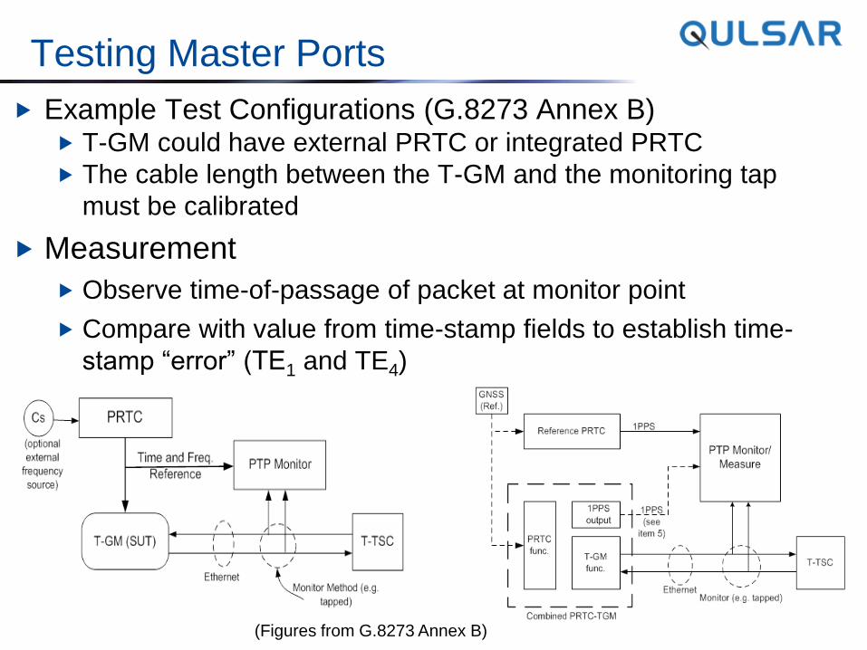
Example Test Configurations (G.8273 Annex B) T-GM could have external PRTC or integrated PRTC
The cable length between the T-GM and the monitoring tap
must be calibrated
Measurement
Observe time-of-passage of packet at monitor point
Compare with value from time-stamp fields to establish time-
stamp “error” (TE1 and TE4)
(Figures from G.8273 Annex B)
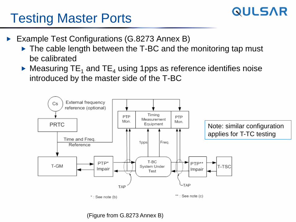
Testing Master Ports
Example Test Configurations (G.8273 Annex B)
The cable length between the T-BC and the monitoring tap must
be calibrated
Measuring TE1 and TE4 using 1pps as reference identifies noise
introduced by the master side of the T-BC
Note: similar configuration
applies for T-TC testing
(Figure from G.8273 Annex B)
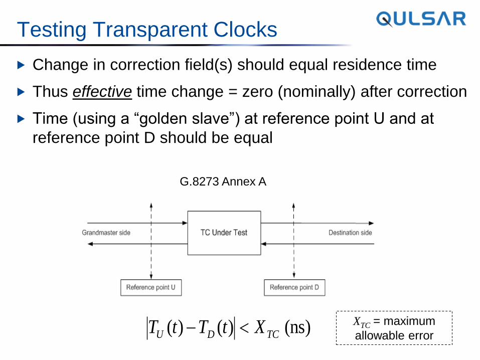
Testing Transparent Clocks
Change in correction field(s) should equal residence time
Thus effective time change = zero (nominally) after correction
Time (using a “golden slave”) at reference point U and at
reference point D should be equal
G.8273 Annex A
(ns) )()( TCDU XtTtT XTC = maximum
allowable error
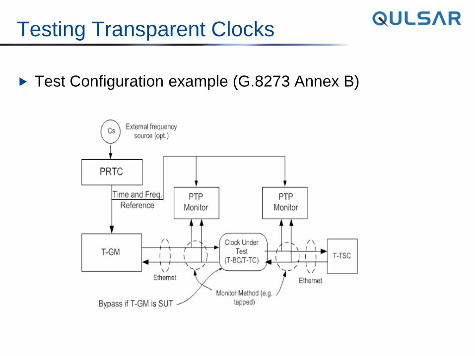
Testing Transparent Clocks
Test Configuration example (G.8273 Annex B)
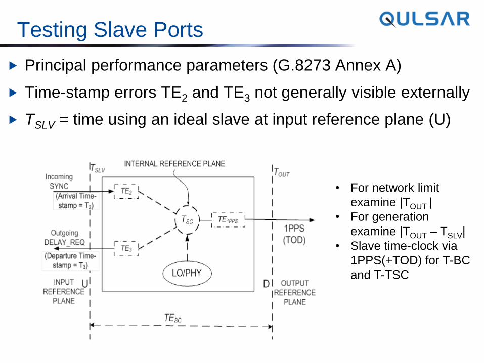
Testing Slave Ports
Principal performance parameters (G.8273 Annex A)
Time-stamp errors TE2 and TE3 not generally visible externally
TSLV = time using an ideal slave at input reference plane (U)
• For network limit
examine |TOUT |
• For generation
examine |TOUT – TSLV|
• Slave time-clock via
1PPS(+TOD) for T-BC
and T-TSC
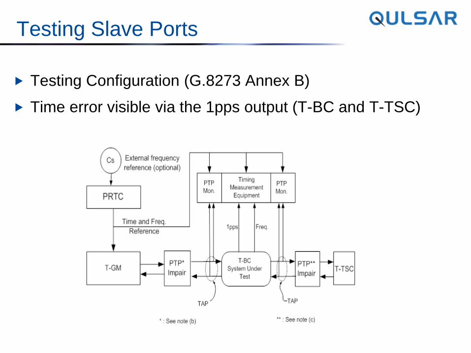
Testing Slave Ports
Testing Configuration (G.8273 Annex B)
Time error visible via the 1pps output (T-BC and T-TSC)
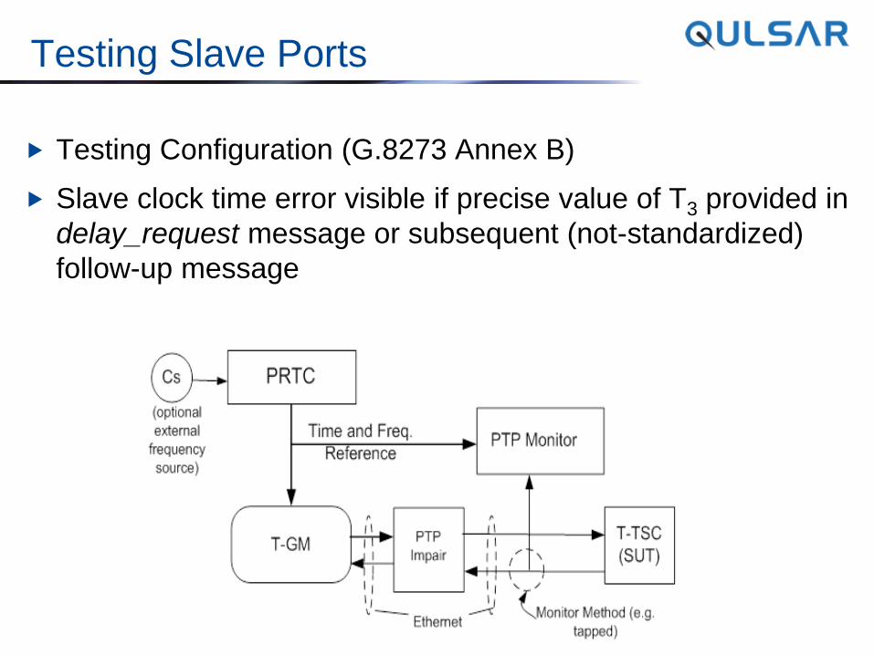
Testing Slave Ports
Testing Configuration (G.8273 Annex B)
Slave clock time error visible if precise value of T3 provided in
delay_request message or subsequent (not-standardized)
follow-up message
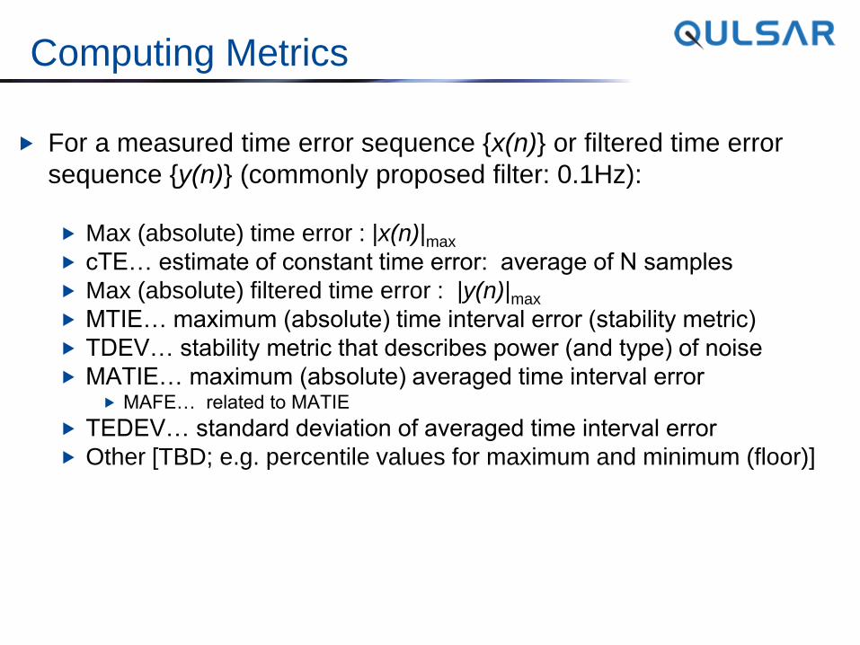
Computing Metrics
For a measured time error sequence {x(n)} or filtered time error
sequence {y(n)} (commonly proposed filter: 0.1Hz):
Max (absolute) time error : |x(n)|max
cTE… estimate of constant time error: average of N samples
Max (absolute) filtered time error : |y(n)|max
MTIE… maximum (absolute) time interval error (stability metric)
TDEV… stability metric that describes power (and type) of noise
MATIE… maximum (absolute) averaged time interval error MAFE… related to MATIE
TEDEV… standard deviation of averaged time interval error
Other [TBD; e.g. percentile values for maximum and minimum (floor)]
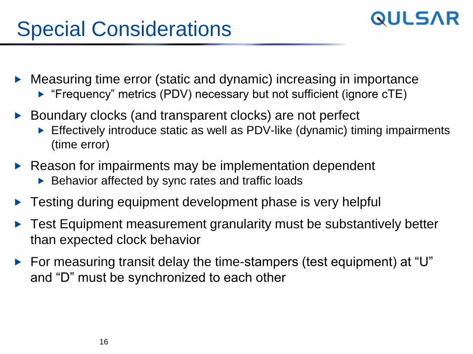
Special Considerations
Measuring time error (static and dynamic) increasing in importance “Frequency” metrics (PDV) necessary but not sufficient (ignore cTE)
Boundary clocks (and transparent clocks) are not perfect Effectively introduce static as well as PDV-like (dynamic) timing impairments
(time error)
Reason for impairments may be implementation dependent Behavior affected by sync rates and traffic loads
Testing during equipment development phase is very helpful
Test Equipment measurement granularity must be substantively better
than expected clock behavior
For measuring transit delay the time-stampers (test equipment) at “U”
and “D” must be synchronized to each other
16
17
Thank You! Questions?
Back-up Slides
18
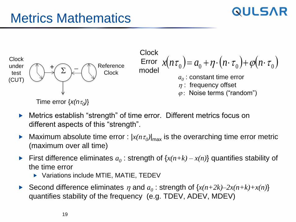
Metrics Mathematics
Metrics establish “strength” of time error. Different metrics focus on
different aspects of this “strength”.
Maximum absolute time error : |x(nt0)|max is the overarching time error metric
(maximum over all time)
First difference eliminates a0 : strength of {x(n+k) – x(n)} quantifies stability of
the time error Variations include MTIE, MATIE, TEDEV
Second difference eliminates h and a0 : strength of {x(n+2k)–2x(n+k)+x(n)}
quantifies stability of the frequency (e.g. TDEV, ADEV, MDEV)
19
Clock
under
test
(CUT)
+ S Reference
Clock
Time error {x(nt0)}
Clock
Error
model 0000 ttht nnanx
a0 : constant time error
h : frequency offset
: Noise terms (“random”)
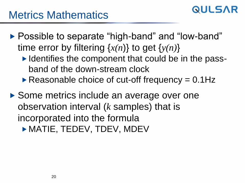
Metrics Mathematics
Possible to separate “high-band” and “low-band”
time error by filtering {x(n)} to get {y(n)} Identifies the component that could be in the pass-
band of the down-stream clock
Reasonable choice of cut-off frequency = 0.1Hz
Some metrics include an average over one
observation interval (k samples) that is
incorporated into the formula MATIE, TEDEV, TDEV, MDEV
20
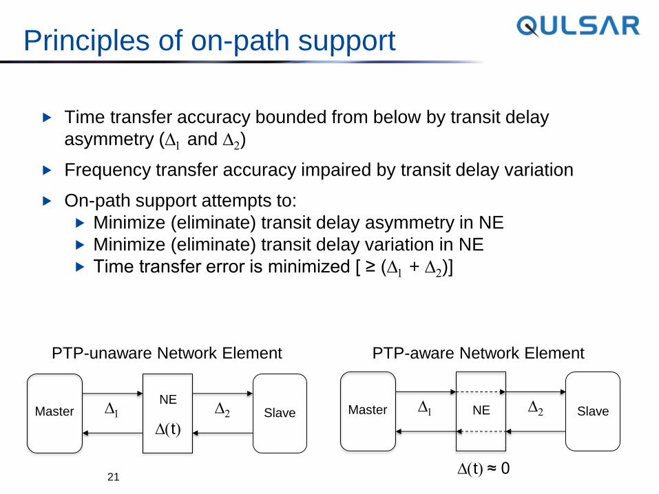
Principles of on-path support
Time transfer accuracy bounded from below by transit delay
asymmetry (D1 and D2)
Frequency transfer accuracy impaired by transit delay variation
On-path support attempts to:
Minimize (eliminate) transit delay asymmetry in NE
Minimize (eliminate) transit delay variation in NE
Time transfer error is minimized [ ≥ (D1 + D2)]
21
Master Slave NE
D1 D2
Dt
PTP-unaware Network Element
Master Slave NE D1 D2
Dt ≈ 0
PTP-aware Network Element
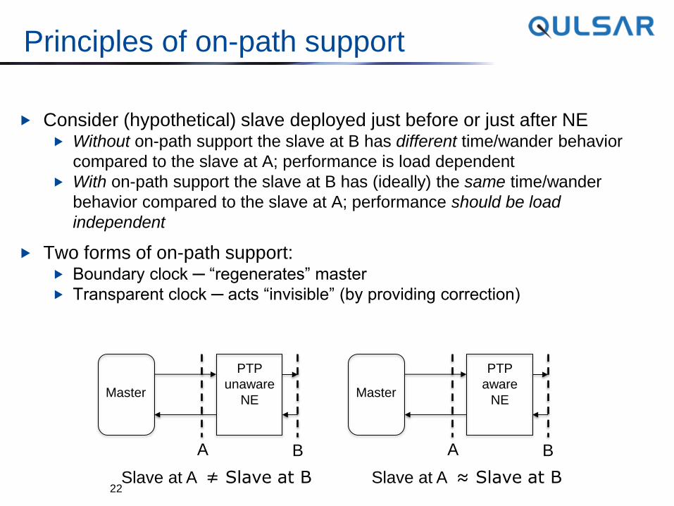
Principles of on-path support
Consider (hypothetical) slave deployed just before or just after NE Without on-path support the slave at B has different time/wander behavior
compared to the slave at A; performance is load dependent
With on-path support the slave at B has (ideally) the same time/wander
behavior compared to the slave at A; performance should be load
independent
Two forms of on-path support: Boundary clock ─ “regenerates” master
Transparent clock ─ acts “invisible” (by providing correction)
22
Master
PTP
unaware
NE
A B
Slave at A ≠ Slave at B
Master
PTP
aware
NE
A B
Slave at A ≈ Slave at B
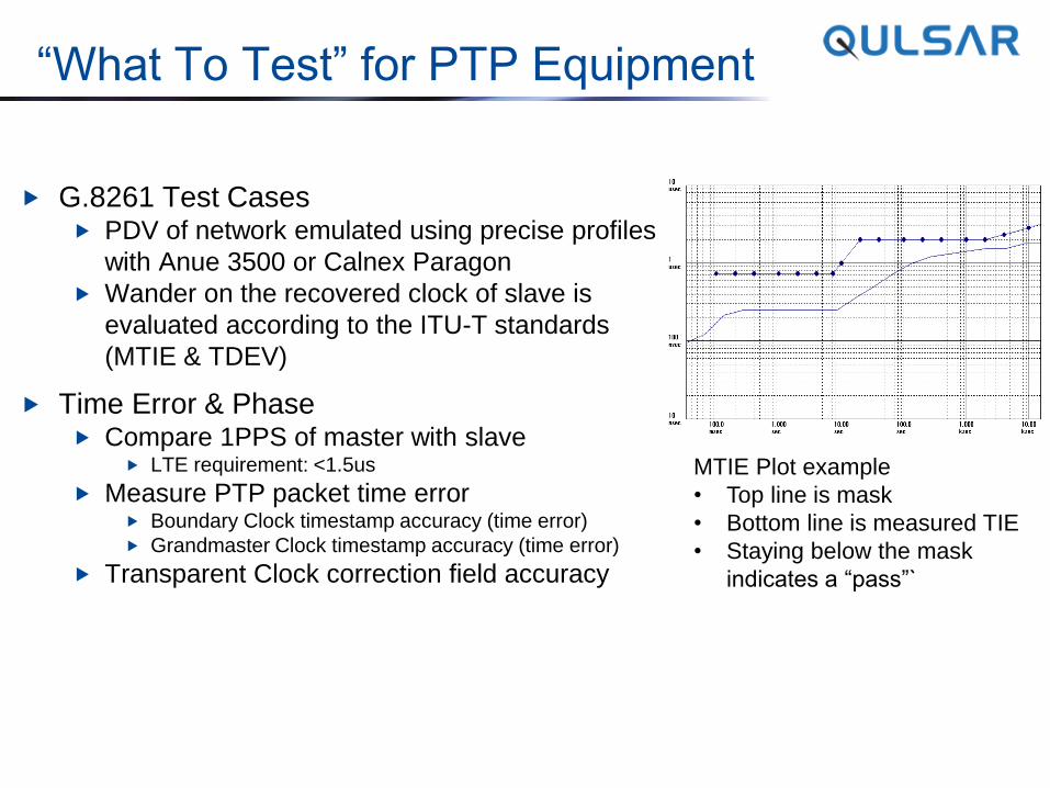
“What To Test” for PTP Equipment
G.8261 Test Cases PDV of network emulated using precise profiles
with Anue 3500 or Calnex Paragon
Wander on the recovered clock of slave is
evaluated according to the ITU-T standards
(MTIE & TDEV)
Time Error & Phase Compare 1PPS of master with slave
LTE requirement: <1.5us
Measure PTP packet time error Boundary Clock timestamp accuracy (time error)
Grandmaster Clock timestamp accuracy (time error)
Transparent Clock correction field accuracy
MTIE Plot example
• Top line is mask
• Bottom line is measured TIE
• Staying below the mask
indicates a “pass”`
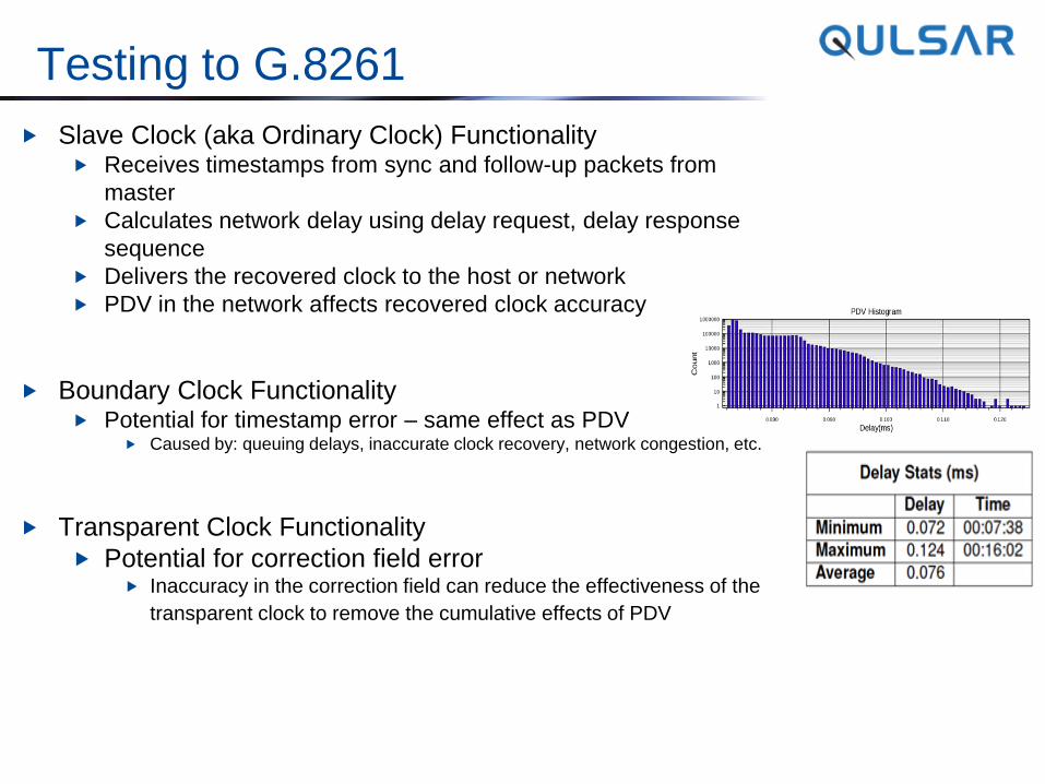
Testing to G.8261
Slave Clock (aka Ordinary Clock) Functionality Receives timestamps from sync and follow-up packets from
master
Calculates network delay using delay request, delay response
sequence
Delivers the recovered clock to the host or network
PDV in the network affects recovered clock accuracy
Boundary Clock Functionality Potential for timestamp error – same effect as PDV
Caused by: queuing delays, inaccurate clock recovery, network congestion, etc.
Transparent Clock Functionality
Potential for correction field error Inaccuracy in the correction field can reduce the effectiveness of the
transparent clock to remove the cumulative effects of PDV
Boundary/Transparent Clock Testing Suggested Best Practices
Monitoring/measuring time error on both sides of a boundary/transparent clock
Comparison between input and output reveals the static and dynamic impact
of the device and we can verify whether it is affected by Background traffic, incoming and outgoing sync packet interval, QoS, routing, etc
Impairment on both sides of a boundary/transparent clock
Impairment is added between the GM Clock and BC/TC, and between the
BC/TC and slave clock, simultaneously; recovered clock at remote slave is
measured Profiles need to be developed
Measure ToD error and phase (1PPS) error introduced by boundary clocks
Monitor and measure timestamp accuracy of sync, follow-up packets from
master port of boundary clock and measure phase offset of 1PPS between
GM Clock and Slave with boundary clock in between

Thank You!
Further Questions?
Kishan Shenoi CTO, Qulsar, Inc.
Email: [email protected]
www.qulsar.com
@qulsar