Embed Size (px)
Citation preview
j
Summary:
Paper No. 98 3102 An ASAE Meeting Presentation
Testing Stand for Yield Measurement Systems in Combine Harvesters
by
Konnann G., Demmel M., Auerohammer H. Institut für Landtechnik, Technische Universität München
85350 Freising-Weihenstephan, Gennany
Written for Presentation at the 1998 ASAE Annual International Meeting
Sponsored by ASAE
Disney's Coronado Springs Resort Orlando, Florida July 12-16, 1988
To evaluate the influences on the accuracy of yield measurement systems a testing stand was developed. Four yield measurement systems were examined on the testing stand within different operating conditions.
Keywords:
Yield measurement system, testing stand, accuracy , combine harvester.
The author(s) is solely responsible for the content of this technical presentation. The technical presentation does not necessarily reflect the offical position of ASAE, and its printing and distribution does not constitute an endorsement of views which may be expressed.
Technical presentations are not subject to the formal peer review process by ASAE editorial committees; therefore, they are not to be presented as refereed publications.
Quotation from this work should state that it is from presentation made by (name of author) at the listed ASAE meeting.
EXAMPLE-From Author's Last Name, Initials . .,Title of Presentation". Presented at the Date and Title of meeting. Paper No. X. ASAE, 2950 Niles Rd., St. Joseph, MI 49085-9659 USA. For information about securing permission to reprint or reproduce a technical presentation, please address inquiries to ASAE.
ASAE, 2950 Niles Rd., St. Joseph, MI 49085-9659 USA Voice: 616.429.0300 FAX: 616429.3852 E-Mail: <[email protected]>

Testing stand for yield measurement systems in combine harvesters
Kormann G., Auerohammer H., Demmel M. Institut für Landtechnik, Technische Universität München Am Staudengarten 2, 85350 Freising-Weihenstephan, Germany
Introduction For precision farming new ideas in agricultural engineering are needed. As a result of the increased capital requirement for agricultural machinery initial forms of multi concem machine usage were created. Therefore coordination of all machines are necessary. Apart from the pure work completion, information about the yield variation within the rotations was thus in many cases also taken out of the concem. The hitherto closed information circuit of own management, with extensive knowledge of the local circumstances, was broken.
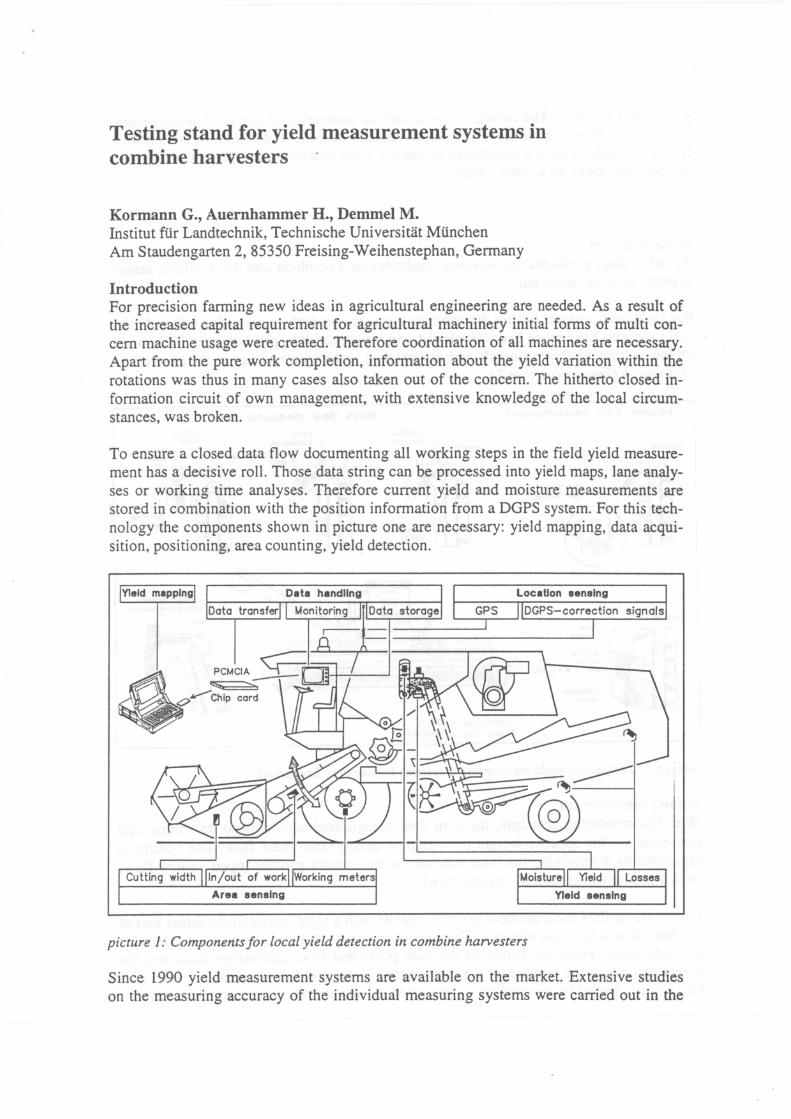
To ensure a closed data flow documenting all working steps in the field yield measurement has a decisive roll. Those data string can be processed into yield maps, lane analyses or working time analyses. Therefore current yield and moisture measurements are stored in combination with the position information from a DGPS system. Forthis technology the components shown in picture one are necessary: yield mapping, data acquisition, positioning, area counting, yield detection.
Yleld mapplng Data handllng
Doto tronsfer Monitaring Doto storoge
r---------'
Cutting width
picture 1: Components for local yield detection in combine harvesters
Since 1990 yield measurement systems are available on the market. Extensive studies on the measuring accuracy of the individual measuring systems were carried out in the
years 1991 to 1995. The results showed various accuracies of the yield measurement systems, but details about the error sources couldn't be evaluated within the field trails. It was the aim, to have a possibility to test the yield measurement systems within weil defined conditions on a testing stand.
State of the art To solve those problems the working conditions on a combine and the available sensor systems must be found out.
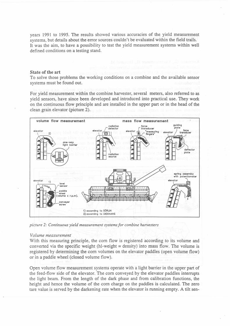
For yield measurement within the combine harvester, several meters, also referred to as yield sensors, have since been developed and introduced into practical use. They work on the continuous flow principle and are installed in the upper part or in the head of the clean grain elevator (picture 2).
volume flow measurement
elevotor Ievei sonsor
paddle ~_.,_~wheel
( volume x r.p.m).
1) occordlng to SÖRUN 2) occording to OIEKHANS
mass flow measurement force transducer
"meoaurlng tlngers"
picture 2: Continuous yield measurement systemsfor combine harvesters
Valurne measurement
guldlng plate
spring asaembly with potentlometer
With this measuring principle, the com flow is registered according to its volume and converted via the specific weight (hl-weight = density) into mass flow. The volume is registered by determining the com volumes on the elevator paddles ( open volume flow) or in a paddle wheel (closed volume flow).
Open volume flow measurement systems operate with a light barrier in the upper part of the feed-flow side of the elevator. The com conveyed by the elevator paddles interrupts the light beam. From the length of the dark phase and from calibration functions, the height and hence the volume of the com charge on the paddles is calculated. The zero tare value is served by the darkening rate when the elevator is running empty. A tilt sen-
sor is designed to compensate the influence of a non-uniform lading of the elevator paddles on a side slope. The hl-weight, which has to be deterrnined with a beambalance, is used by the evaluation electronics to deduce the mass flow [t/h]. As in all other measuring systems, this is converted into the area yield [t/ha] by being offset against the harvested area produced from the entered cutting width and measured threshing distance (wheel sensor). In addition, the harvested area is used to determine the areal output [ha/h].
With this particular system, the mass flow and the yield can be adjusted to Standard moisture by the use of a continuous-working moisture sensor in the grain thank filling worm.
For the 1997 harvest season, the company CLAAS is offering the volumetrically operating QUANTIM:ETER 2 measuring system with connection to the CEBIS or IMO onboard electronics (LEXION) and to the ACT Terminal (retrofitting to DOMINA TOR). The sensor arrangement is identical to that of the RDS CERES 2 system. The balancing of the measurement values is effected either directly in the on-board electronics (LEXION series) or in the ACT Terminal.
Mass flow determination In determining the mass of the corn flow, either the force/impetus measurement principle or the absorption of gamma rays by mass in a radiometric measuring system is relied upon. The DAT AVISION FLOWCONTROL yield measuring system from MASSEY FERGOUSON is arranged in the elevator head and operates according to the radiometric principle.
The corn discharged from the elevator paddles passes through the region between weakly radioactive source (Americium 241, activity 35 MBq) and radiation sensor. As it does so, radiation is absorbed. The degree of absorption corresponds to the areal weight of the corn in the region of the measuring window. The material velocity, which is deduced from the elevator speed, is used to calculate the massflow. Similar systems are today also used in food processing.
From the 1997 season, the measuring system is being used in combination with new electronics installation (BUS system) and new terminal and bears the name FJELDSTAR.
The YIELD MONITOR 2000 yield measuring system from Ag-Leader (identical in construction to the LH AGRO LH 565, CASE AFS and Deutz-Fahr Teris) uses the force/impetus measurement and is likewise fitted in the elevator head in the discharge path of the corn. The sensor consists of a baffle plate which is fitted to a forcemeasuring cell. Corn hitting the baffle plate causes a force effect at right angles to the bending bar, which force effect is electrically sensed with strain gauges. Since this impetus is the product of mass and velocity, it is possible to calculate the mass flow. The material velocity is deduced, in turn, from the elevator velocity.
The yield measurement system GRAIN-TRAK from MICRO-TRAK (sensor identical in construction with the MÜLLER UNIPILOT system) works also on the force/impetus measurement principle. Instead of the baffle plate two measuring fingers are used. The speed of the grain is detected by measuring the frequency of the grain bundles coming from each elevator paddle.
JOHN DEERE Greenstar system measures the force/impetus by the elongation of a potentiometer. A half rounded impactplate is mounted on spring elements. According to HOOK the deformation of a spring is depending on the added force. So the elongation of a potentiometer can be converted into the impetus and to the rnassflow. The material velocity is deduced, in turn, from the elevator velocity.
For all those measurernent systerns continuous working moisture sensors integrated in the grain tank filling worm are available. This way the mass flow and the yield can be adjusted to standard moisture.
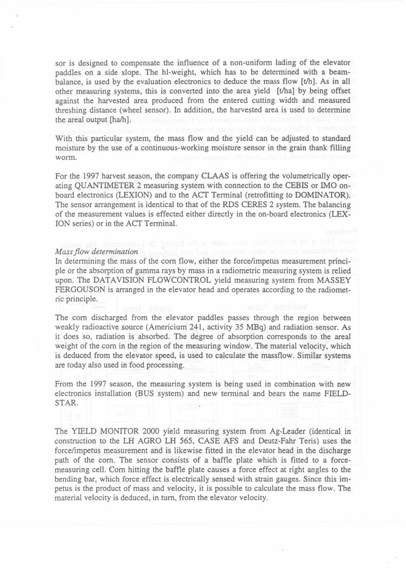
Problem Since 1991 a lot of field trials were rnade at the Institut für Landtechnik. The results show calibration errors (= mean deviation) and also different measuring errors (= standard deviation or 95 % confidential interval) (picture 3).
volume flow
12
-"' 2 8 c: 6
·~ 4+---....... c 2 ., E 0 -+---="':".----., ~ -2 0 E-4-+---- -6 0
a -8+---~-1o
mass flow
r.ilCcon-
lnt....,. ~--.. 8,40
m~ -1,04 - -a.-48
100
80 c: .2 ö
60 ~
40 1i a.
~ 20 ~ ...
picture 3: Accuracy and error sources ofyield measurement systems in combine harvesters
The mean relative error represents the measure of the calibration quality. It should ideally measure zero, or at least close to zero. This requirement was successfully achieved by all meters. The standard deviation (s) or the 95% confidence interval is the measure of the measuring accuracy. The 95% confidence interval indicates the range of error within which around 2/3 of all measurements lie. Despite the different measuring principles, all measuring systems are characterized by approximately equal ranges of error between ± 7 % and ± 8 %.
Details about the error sources couldn't be evaluated in detail within the field trials. Therefore it was the aim, to analyze the influence of different working conditions on the measuring systems accuracy.
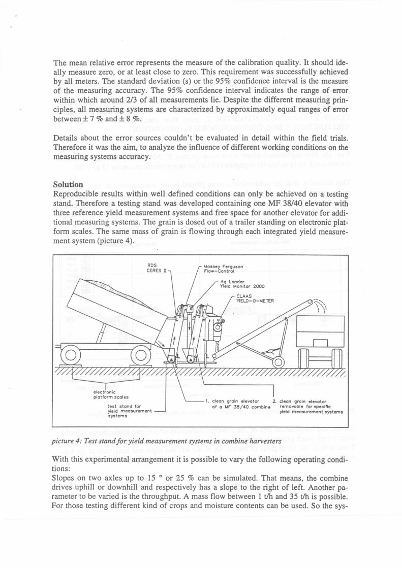
Solution Reproducible results within weil defined conditions can only be achieved on a testing stand. Therefore a testing stand was developed containing one MF 38/40 elevator with three reference yield measurement systems and free space for another elevator for additional measuring systems. The grain is dosed out of a trailer standing on electronic platforrn scales. The same mass of grain is flowing through each integrated yield measurement system (picture 4).
test stand for yield meosurement systems
Ag Leader Yield Monitor 2000
1. clean groin elevotor 2. clean groin elevotor of o MF 38/40 combine removoble for specific
yield meosurement systems
picture 4: Test standfor yield measurement systems in combine harvesters
With this experimental arrangement it is possible to vary the following operating conditions: Slopes on two axles up to 15 ° or 25 % can be simulated. That means, the combine drives uphill or downhill and respectively has a slope to the right of left. Another parameter to be varied is the throughput. A mass flow between I tJh and 35 tJh is possible. For those testing different kind of crops and moisture contents can be used. So the sys-
tems accuracy depending on slopes and on throughput can be determined for different kind of crops.
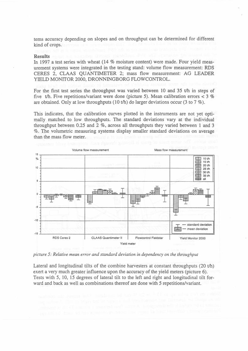
Results In 1997 a test series with wheat (14% moisture content) were made. Four yield measurement systems were integrated in the testing stand: volume flow measurement: RDS CERES 2, CLAAS QUANTIMETER 2; mass flow measurement: AG LEADER YIELD MONITOR 2000, DRONNINGBORG FLOWCONTROL.
For the first test series the throughput was varied between 10 and 35 tlh in steps of five tlh. Five repetitions/variant were done (picture 5). Mean calibration errors < 3 % are obtained. Only at low throughputs (10 tlh) do larger deviations occur (3 to 7 %).
This indicates, that the calibration curves plotted in the instruments are not yet optimally matched to low throughputs. The standard deviations vary at the individual throughput between 0.25 and 2 %, across all throughputs they varied between 1 and 3 %. The volumetric measuring systems display smaller standard deviations on average than the mass flow meter.
Volume flow measurement Mass flow measurement
15.---------------,---------------,---------------~-------r======~ % ml!!IJ 1 0 tlh
~ 151/h m 2ot/h
10+---------------~--------------~--------------+-------~~251/h
I:E 30 tlh Im 351/h fl!§B!Iall
·10+---------------,r--------------,r--------------+r--------------~ ..I.. - standard deviation
~- mean deviation
-15~--------------~--------------~--------------~==============~ RDS Ceres 2 CLAAS Quantimeter II Flowcontrol Fieldstar Yield Monitor 2000
Yield meter
picture 5: Relative mean error and standard deviation in dependency on the throughput
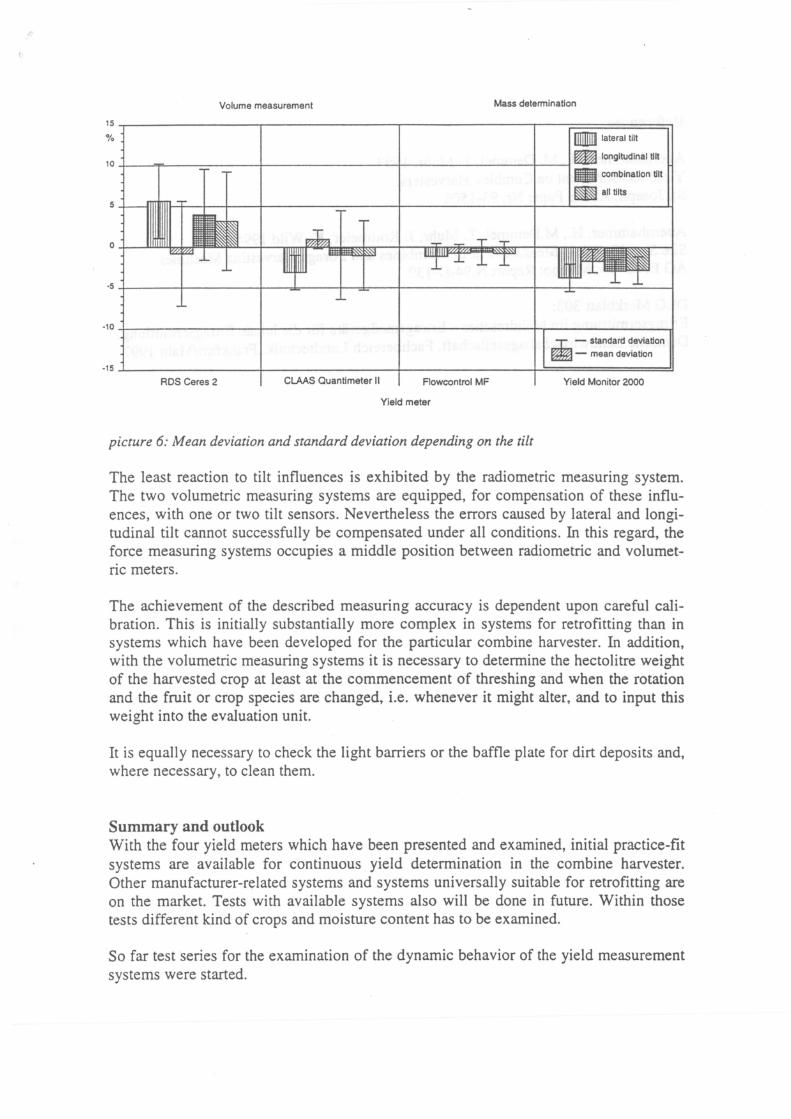
Lateral and longitudinal tilts of the combine harvesters at constant throughputs (20 t/h) exert a very much greater influence upon the accuracy of the yield meters (picture 6). Tests with 5, 10, 15 degrees of lateral tilt to the left and right and longitudinal tilt forward and back as weil as combinations thereof are done with 5 repetitions/variant.
Volume measurement Mass deterrnination
15~---------------r--------------~r---------------r---r===========~ ffiiiDill lateral tilt %
~ longitudinal tilt 10+---~----=-----~--------------~r---------------+-__,~
• combination tilt
~alltilts
·10+----------------r--------------~r---------------+T--------------~ ..I.. - standard deviation ~- mean deviation
·15i---------------~--------------~~--------------~==============~ RDS Ceres 2 CLAAS Quantimeter II Flowcontrol MF Yield Monitor 2000
Yield meter
picture 6: Mean deviation and standard deviation depending on the tilt
The least reaction to tilt influences is exhibited by the radiometric measuring system. The two volumetric measuring systems are equipped, for compensation of these influences, with one or two tilt sensors. Nevertheless the errors caused by lateral and longitudinal tilt cannot successfully be compensated under all conditions. In this regard, the force measuring systems occupies a middle position between radiometric and volumetric meters.
The achievement of the described measuring accuracy is dependent upon careful calibration. This is initially substantially more complex in systems for retrofitting than in systems which have been developed for the particular combine harvester. In addition, with the volumetric measuring systems it is necessary to determine the hectolitre weight of the harvested crop at least at the commencement of threshing and when the rotation and the fruit or crop species are changed, i.e. whenever it might alter, and to input this weight into the evaluation unit.
lt is equally necessary to check the light barriers or the baffle plate for dirt deposits and, where necessary, to clean them.
Summary and outlook With the four yield meters which have been presented and examined, initial practice-fit systems are available for continuous yield determination in the combine harvester. Other manufacturer-related systems and systems universally suitable for retrofitting are on the market. Tests with available systems also will be done in future. Within those tests different kind of crops and moisture content has to be examined.
So far test series for the examination of the dynamic behavior of the yield measurement systems were started.
References
Auernhammer, H., M. Demmel, T. Muhr, 1993: Yield measurement on Combine Harvesters. St. Joseph, ASAE Paper Nr. 93-1506
Auernhammer, H., M.Demmel, T. Muhr, J. Rottmeier, K. Wild 1994: Site Specific Yield Measurement in Combines and Forage Harvesting Machines. AG ENG '94; Milano: Report N.94-D-139
DLG Merkblatt 303: Ertragsermittlung im Mähdrescher- Ertragsmeßgeräte für die lokale Ertragsermittlung. Deutsche Landwirtschaftsgesellschaft, Fachbereich Landtechnik, Frankfurt/Main 1997


![SECTION DIVIDER - ENGINE 620DSL - AutoCD.BIZENGINE 620 DSLP TO NO H7] MFMF000 COMBINE COMBINE COMBINE,,,T TT - - - - 1637219 1637219 MASSEYMASSEYNN 9 9 MFMF000 COMBINE COMBINE COMBINE,,,T](https://img.pdfslide.us/doc/110x75/60fa78029790e3414c2da5c0/section-divider-engine-620dsl-engine-620-dslp-to-no-h7-mfmf000-combine-combine.jpg)