Embed Size (px)
Citation preview
Testing Solutions for Protection Systems
Reliable and Efficient Testing for all Kinds of Protective Relays
2
Protection Testing: Ensuring Reliability
Protection systems play a key role for the safe and reliable opera-tion of today’s electricity power systems. This is relevant for all power system grids in generation, transmission and distribution, industrial, railway, and marine applications. Properly working protection devices help to maintain the safety of the system and to safeguard assets from damage while assisting to ensure security of supply. In order to guarantee reliable operation, protection relays must be tested throughout their life-cycle, from their initial development through production and commissioning to periodical maintenance during operation.
There are many different reasons why protection relays may suffer from malfunctions and these can vary depending on the various generations of relay that are in service today: Electromechanical
relays may cause problems due to aging of mechanical components, such as coils or contacts, static relays are subject to drifting or can have failures of electronic circuits or components, and numerical relays may exhibit undesirable effects because of software
issues, e.g. following firmware updates. Hence, commissioning and routine testing should be performed thoroughly so that shortcomings in the reliability of the protection system are discovered before a power system fault occurs.
In addition to numerous technical challenges, commissioning engineers and protection departments are also faced with the need to operate efficiently to meet the economic demands of developments such as the liberalization of the energy market. The use of innovative testing solutions from OMICRON offers a high degree of efficiency and effectiveness for testing the complete range of different protection equipment, and contributes to the future reliability of the protection system.
Electrical Utilities
Protection devices used in electricity generation are often customized for special applications and philosophies and therefore require flexible testing equipment to support special test procedures. The testing philoso-
phy of OMICRON allows a combination of individual testing functions – both standard and customized – within an overall test plan, which also allows the generation of flexible, comprehensive test reports.
Protection engineers working with transmission systems are increasingly faced with multifunctional protection relays with a high degree of complexity that have to be tested efficiently. For this purpose, OMICRON
provides a template library with test plans for commonly used relays. For applications which go beyond the scope of the usual parameter testing and functional verification, the editing and playing back of recorded transient fault signals and the calculation of fault conditions by means of network simulation is also possible.
The requirements for protection engineers in the field of distribution are characterized by a huge number of feeders, where routine testing has to be carried out very efficiently. OMICRON’s unique approach of using one
central test document allows the easy application of predefined test plans and the re-use of existing automated test procedures for maintenance and routine testing.
In many cases, testing in substations in transmission and distribu-tion networks also involves monitoring of messages and process control functions. The OMICRON test modules support such tasks and also offer full integration of the functionality of the communi-cation protocol defined by the IEC 61850 specification.
3
Industry
A protection system in a large industrial plant often incorporates a large number of different devices from various manufacturers. OMICRON provides predefined test templates for many of these different relays and thereby
facilitates efficient testing. Hence, downtime in the plant for testing purposes can be kept extremely short.Engineers in industry, who are responsible for the protection equipment, often also take care of a wide range of other tasks. The operation of test equipment which is not used on a daily basis should therefore be as simple as possible. OMICRON test sets provide an intuitive testing environment for quick and simple manual operation.
Test equipment with a high degree of versatility is ideally suited for industry. In addition to their protection testing functionality, OMICRON test sets can also be used for calibrating measuring transducers, which are used in large numbers in industrial facilities for interfacing electrical quantities with control systems, as well as electricity meters, power quality measurement devices and other measurement equipment.
Manufacturers
Very specific requirements apply to test equipment used by manufacturers of protec-tion devices. High precision, flexibility, and reliability are indispensable requirements for its use in the development process as well as
type testing and testing during the manufacturing process. To facilitate acceptance testing the test sets have to be integrated into the production process and the documentation system.
OMICRON test sets have been developed in close cooperation with relay manufacturers. Therefore, they meet all of these require-ments and are the preferred solution for this field of application all over the world. An open programming interface facilitates the integration of the test sets into the manufacturers´ own test environments.
This brochure offers information about the following:
The CMC Test Sets ........................................................................4Manual Testing.............................................................................6Automated Testing of Protection Functions ...................................7Efficient Use of Test Plans .............................................................8Programming with CM Engine ......................................................9Protection Testing Library PTL ...................................................... 10Testing in IEC 61850 Environments ............................................. 12Network Simulation with NetSim ................................................ 14Measuring and Recording with EnerLyzer .................................... 14Line Impedance Measurement and k-Factor Determination .......... 15Coupling Impedance Measurement of Parallel Systems ................ 15Current Transformer Testing ........................................................ 15
Service Providers
Carrying out the commissioning and routine testing of protection systems requires test equipment with a high level of flexibility. This is particularly relevant if the services are provided internationally. OMICRON test sets
are used in more than 130 countries and the experience gained is incorporated into the products and ensures the flexibility demanded by testing companies, such as the ability to work with different protection technologies and philosophies.Since service providers often work under extreme time pressure, the test equipment has to be very efficient. The test philosophy of OMICRON allows tests to be largely prepared in the office and thereby minimizes the necessary time on-site.It is beneficial for service providers to keep the number of differ-ent types of test sets taken on site to a minimum. OMICRON’s versatility with the integration of tools such as analog measure-ment and transient signal recording helps to meet this objective.
Railway
Testing the protection systems of electrified railways presents some special challenges. Systems in various countries often have special frequencies and different numbers of phases and hence a flexible testing system is required.
OMICRON test sets can meet these needs with users being offered the same testing performance and convenience as for applications in other power systems.
4
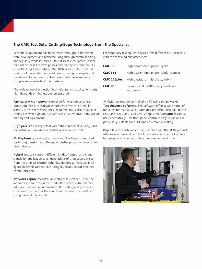
Secondary equipment has to be tested throughout its lifetime from development and manufacturing through commissioning and regularly while in service. OMICRON test equipment is ideal for each of these life-cycle phases and for any environment. As a reliable long-term partner, OMICRON offers state-of-the-art testing solutions which are continuously being developed and maintained to help users to keep pace with the increasingly complex requirements of their systems.
The wide range of protection technologies and applications puts high demands on the test equipment used:
Particularly high power is required for electromechanical protection relays, considerable numbers of which are still in service. A test set meeting these requirements is also capable of testing CTs with high input currents as an alternative to the use of primary test equipment.
High precision is important when the equipment is being used for calibration, for which a reliable reference is crucial.
Multi-phase capability (6 currents and 4 voltages) is required for testing transformer differential, busbar protection or synchro-nizing devices.
Hybrid test sets support different kinds of output and input signals for application to all generations of protection devices from the simplest electromechanical designs to the latest Intel-ligent Electronic Devices (IED) using IEC 61850 based Ethernet communication.
Network capability offers advantages for test set-ups in the laboratory or for tests in the production process. An Ethernet interface is a basic requirement for IED testing and provides a convenient method for the connection between the notebook computer and the test set.
For secondary testing, OMICRON offers different CMC test sets with the following characteristics:
CMC 356 High power, multi-phase, hybrid
CMC 353 High power, three-phase, hybrid, compact
CMC 256plus High precision, multi-phase, hybrid
CMC 850 Focused on IEC 61850, very small and light-weight
All CMC test sets are controlled via PC using the powerful Test Universe software. This software offers a wide range of functions for manual and automated protection testing. For the CMC 356, CMC 353, and CMC 256plus the CMControl can be used alternatively. This front panel control is easy to use and is particularly suitable for quick and easy manual testing.
Regardless of which variant the user chooses, OMICRON products offer excellent reliability in the functional assessment of protec-tion relays and other secondary measurement instruments.
The CMC Test Sets: Cutting-Edge Technology from the Specialist
5
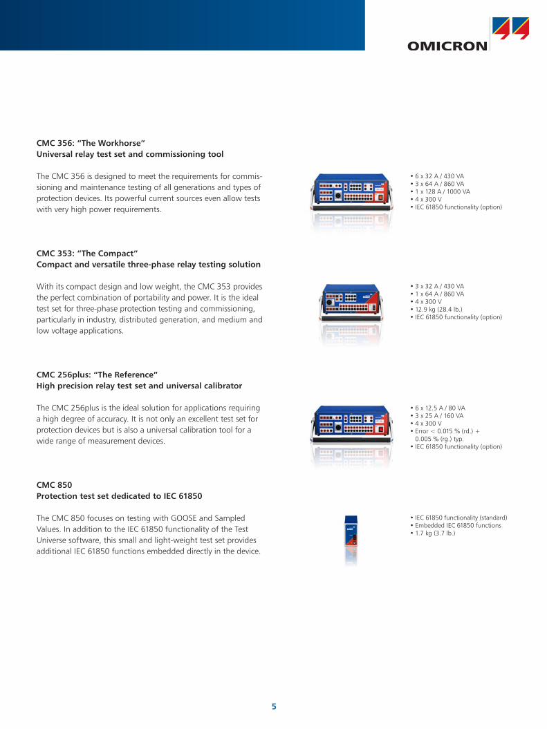
CMC 256plus: “The Reference”High precision relay test set and universal calibrator
CMC 850Protection test set dedicated to IEC 61850
The CMC 850 focuses on testing with GOOSE and Sampled Values. In addition to the IEC 61850 functionality of the Test Universe software, this small and light-weight test set provides additional IEC 61850 functions embedded directly in the device.
CMC 356: “The Workhorse”Universal relay test set and commissioning tool
The CMC 356 is designed to meet the requirements for commis-sioning and maintenance testing of all generations and types of protection devices. Its powerful current sources even allow tests with very high power requirements.
CMC 353: “The Compact”Compact and versatile three-phase relay testing solution
With its compact design and low weight, the CMC 353 provides the perfect combination of portability and power. It is the ideal test set for three-phase protection testing and commissioning, particularly in industry, distributed generation, and medium and low voltage applications.
•6 x 12.5 A / 80 VA•3 x 25 A / 160 VA•4 x 300 V•Error < 0.015 % (rd.) +
0.005 % (rg.) typ.•IEC 61850 functionality (option)
•3 x 32 A / 430 VA•1 x 64 A / 860 VA•4 x 300 V•12.9 kg (28.4 lb.)•IEC 61850 functionality (option)
•6 x 32 A / 430 VA•3 x 64 A / 860 VA•1 x 128 A / 1000 VA•4 x 300 V•IEC 61850 functionality (option)
The CMC 256plus is the ideal solution for applications requiring a high degree of accuracy. It is not only an excellent test set for protection devices but is also a universal calibration tool for a wide range of measurement devices.
•IEC 61850 functionality (standard)•Embedded IEC 61850 functions•1.7 kg (3.7 lb.)
6
Manual Testing
To control the CMC test set, OMICRON provides the Test Universe software which offers a wide range of specialized test modules for automated testing of secondary devices. For applications where test engineers simply want to apply current and voltage to a test object and measure its response as quickly as possible, OMICRON offers two alternatives: the optional front panel control CMControl or the Test Universe software module QuickCMC.
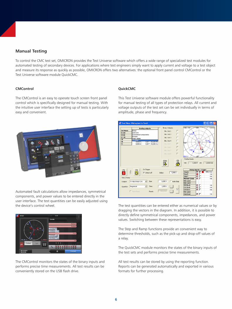
The test quantities can be entered either as numerical values or by dragging the vectors in the diagram. In addition, it is possible to directly define symmetrical components, impedances, and power values. Switching between these representations is easy.
The Step and Ramp functions provide an convenient way to determine thresholds, such as the pick-up and drop-off values of a relay.
The QuickCMC module monitors the states of the binary inputs of the test sets and performs precise time measurements.
All test results can be stored by using the reporting function. Reports can be generated automatically and exported in various formats for further processing.
QuickCMC
This Test Universe software module offers powerful functionality for manual testing of all types of protection relays. All current and voltage outputs of the test set can be set individually in terms of amplitude, phase and frequency.
CMControl
The CMControl is an easy to operate touch screen front panel control which is specifically designed for manual testing. With the intuitive user interface the setting up of tests is particularly easy and convenient.
Automated fault calculations allow impedances, symmetrical components, and power values to be entered directly in the user interface. The test quantities can be easily adjusted using the device’s control wheel.
The CMControl monitors the states of the binary inputs and performs precise time measurements. All test results can be conveniently stored on the USB flash drive.
7
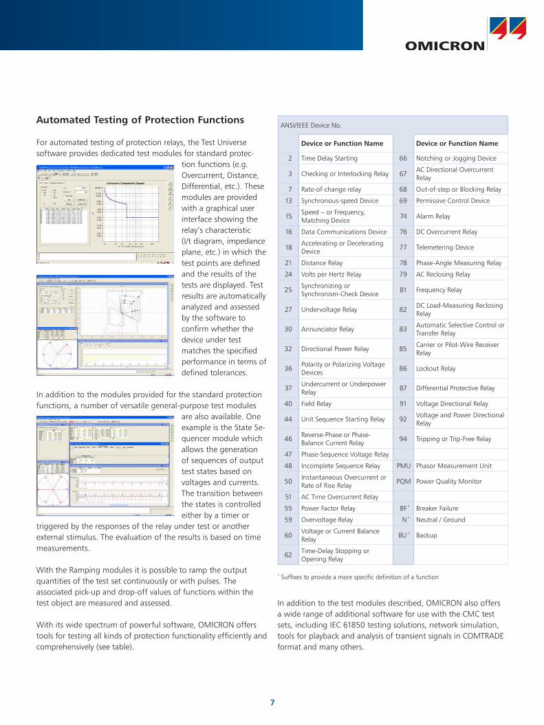
Automated Testing of Protection Functions
For automated testing of protection relays, the Test Universe software provides dedicated test modules for standard protec-
tion functions (e.g. Overcurrent, Distance, Differential, etc.). These modules are provided with a graphical user interface showing the relay’s characteristic (I/t diagram, impedance plane, etc.) in which the test points are defined and the results of the tests are displayed. Test results are automatically analyzed and assessed by the software to confirm whether the device under test matches the specified performance in terms of defined tolerances.
In addition to the modules provided for the standard protection functions, a number of versatile general-purpose test modules
are also available. One example is the State Se-quencer module which allows the generation of sequences of output test states based on voltages and currents. The transition between the states is controlled either by a timer or
triggered by the responses of the relay under test or another external stimulus. The evaluation of the results is based on time measurements.
With the Ramping modules it is possible to ramp the output quantities of the test set continuously or with pulses. The associated pick-up and drop-off values of functions within the test object are measured and assessed.
With its wide spectrum of powerful software, OMICRON offers tools for testing all kinds of protection functionality efficiently and comprehensively (see table).
In addition to the test modules described, OMICRON also offers a wide range of additional software for use with the CMC test sets, including IEC 61850 testing solutions, network simulation, tools for playback and analysis of transient signals in COMTRADE format and many others.
ANSI/IEEE Device No.
Device or Function Name Device or Function Name
2 Time Delay Starting 66 Notching or Jogging Device
3 Checking or Interlocking Relay 67AC Directional Overcurrent Relay
7 Rate-of-change relay 68 Out-of-step or Blocking Relay
13 Synchronous-speed Device 69 Permissive Control Device
15Speed – or Frequency, Matching Device
74 Alarm Relay
16 Data Communications Device 76 DC Overcurrent Relay
18Accelerating or Decelerating Device
77 Telemetering Device
21 Distance Relay 78 Phase-Angle Measuring Relay
24 Volts per Hertz Relay 79 AC Reclosing Relay
25Synchronizing or Synchronism-Check Device
81 Frequency Relay
27 Undervoltage Relay 82DC Load-Measuring Reclosing Relay
30 Annunciator Relay 83Automatic Selective Control or Transfer Relay
32 Directional Power Relay 85Carrier or Pilot-Wire Receiver Relay
36Polarity or Polarizing Voltage Devices
86 Lockout Relay
37Undercurrent or Underpower Relay
87 Differential Protective Relay
40 Field Relay 91 Voltage Directional Relay
44 Unit Sequence Starting Relay 92Voltage and Power Directional Relay
46Reverse-Phase or Phase-Balance Current Relay
94 Tripping or Trip-Free Relay
47 Phase-Sequence Voltage Relay
48 Incomplete Sequence Relay PMU Phasor Measurement Unit
50Instantaneous Overcurrent or Rate of Rise Relay
PQM Power Quality Monitor
51 AC Time Overcurrent Relay
55 Power Factor Relay BF * Breaker Failure
59 Overvoltage Relay N * Neutral / Ground
60Voltage or Current Balance Relay
BU * Backup
62Time-Delay Stopping or Opening Relay
* Suffixes to provide a more specific definition of a function
8
Efficient Use of Test Plans
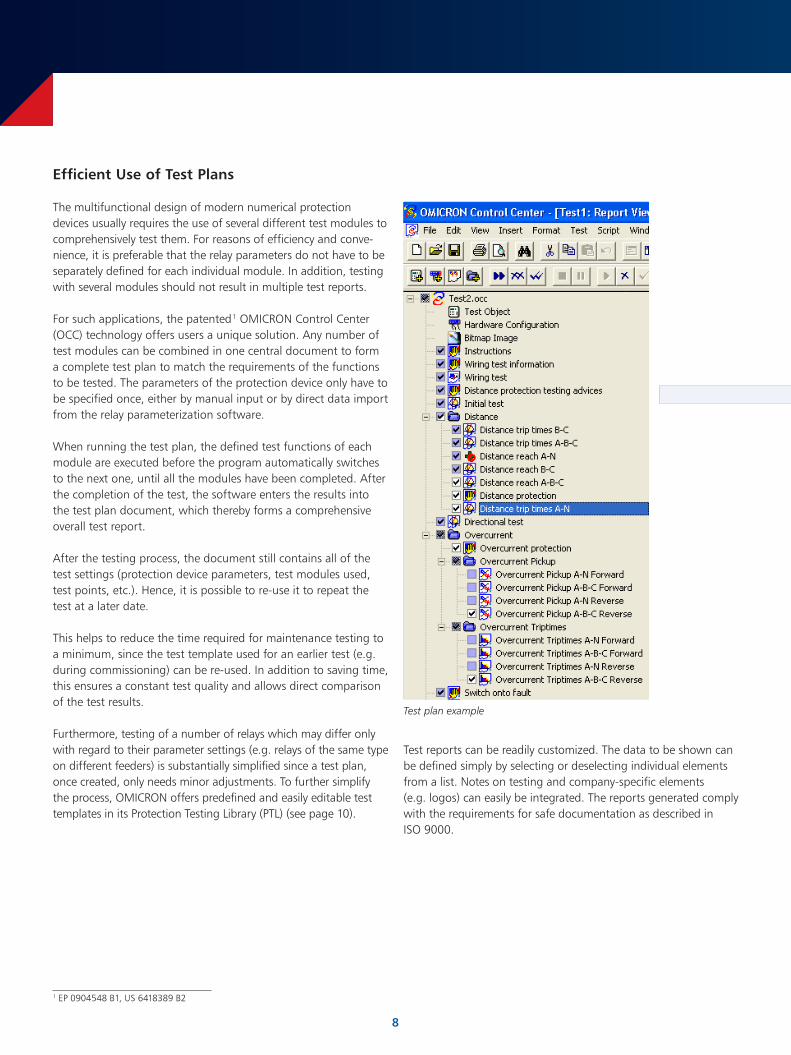
The multifunctional design of modern numerical protection devices usually requires the use of several different test modules to comprehensively test them. For reasons of efficiency and conve-nience, it is preferable that the relay parameters do not have to be separately defined for each individual module. In addition, testing with several modules should not result in multiple test reports.
For such applications, the patented 1 OMICRON Control Center (OCC) technology offers users a unique solution. Any number of test modules can be combined in one central document to form a complete test plan to match the requirements of the functions to be tested. The parameters of the protection device only have to be specified once, either by manual input or by direct data import from the relay parameterization software.
When running the test plan, the defined test functions of each module are executed before the program automatically switches to the next one, until all the modules have been completed. After the completion of the test, the software enters the results into the test plan document, which thereby forms a comprehensive overall test report.
After the testing process, the document still contains all of the test settings (protection device parameters, test modules used, test points, etc.). Hence, it is possible to re-use it to repeat the test at a later date.
This helps to reduce the time required for maintenance testing to a minimum, since the test template used for an earlier test (e.g. during commissioning) can be re-used. In addition to saving time, this ensures a constant test quality and allows direct comparison of the test results.
Furthermore, testing of a number of relays which may differ only with regard to their parameter settings (e.g. relays of the same type on different feeders) is substantially simplified since a test plan, once created, only needs minor adjustments. To further simplify the process, OMICRON offers predefined and easily editable test templates in its Protection Testing Library (PTL) (see page 10).
1 EP 0904548 B1, US 6418389 B2
Test plan example
Test reports can be readily customized. The data to be shown can be defined simply by selecting or deselecting individual elements from a list. Notes on testing and company-specific elements (e.g. logos) can easily be integrated. The reports generated comply with the requirements for safe documentation as described in ISO 9000.
9
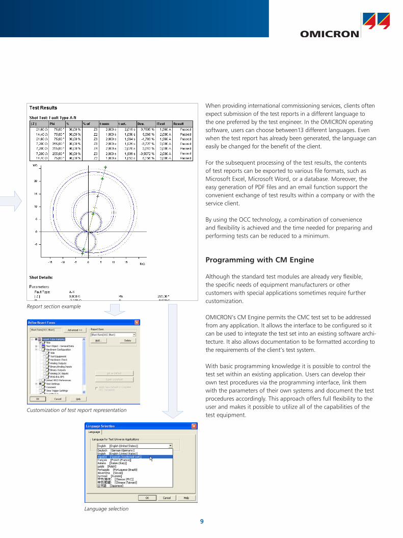
When providing international commissioning services, clients often expect submission of the test reports in a different language to the one preferred by the test engineer. In the OMICRON operating software, users can choose between13 different languages. Even when the test report has already been generated, the language can easily be changed for the benefit of the client.
For the subsequent processing of the test results, the contents of test reports can be exported to various file formats, such as Microsoft Excel, Microsoft Word, or a database. Moreover, the easy generation of PDF files and an email function support the convenient exchange of test results within a company or with the service client.
By using the OCC technology, a combination of convenience and flexibility is achieved and the time needed for preparing and performing tests can be reduced to a minimum.
Programming with CM Engine
Although the standard test modules are already very flexible, the specific needs of equipment manufacturers or other customers with special applications sometimes require further customization.
OMICRON’s CM Engine permits the CMC test set to be addressed from any application. It allows the interface to be configured so it can be used to integrate the test set into an existing software archi-tecture. It also allows documentation to be formatted according to the requirements of the client’s test system.
With basic programming knowledge it is possible to control the test set within an existing application. Users can develop their own test procedures via the programming interface, link them with the parameters of their own systems and document the test procedures accordingly. This approach offers full flexibility to the user and makes it possible to utilize all of the capabilities of the test equipment.
Language selection
Customization of test report representation
Report section example
10
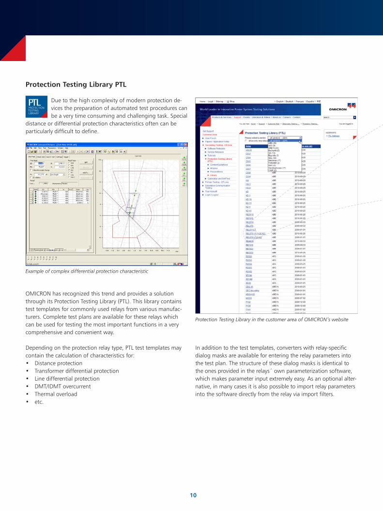
Due to the high complexity of modern protection de-vices the preparation of automated test procedures can be a very time consuming and challenging task. Special
distance or differential protection characteristics often can be particularly difficult to define.
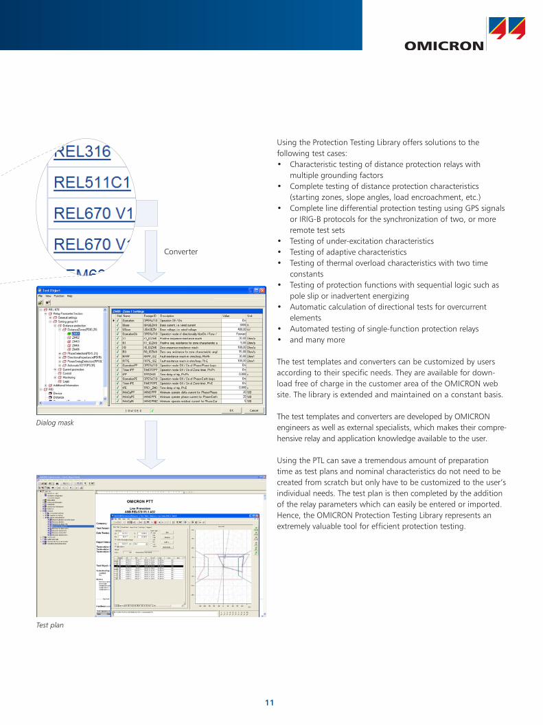
In addition to the test templates, converters with relay-specific dialog masks are available for entering the relay parameters into the test plan. The structure of these dialog masks is identical to the ones provided in the relays´ own parameterization software, which makes parameter input extremely easy. As an optional alter-native, in many cases it is also possible to import relay parameters into the software directly from the relay via import filters.
OMICRON has recognized this trend and provides a solution through its Protection Testing Library (PTL). This library contains test templates for commonly used relays from various manufac-turers. Complete test plans are available for these relays which can be used for testing the most important functions in a very comprehensive and convenient way.
Depending on the protection relay type, PTL test templates may contain the calculation of characteristics for:• Distance protection• Transformer differential protection• Line differential protection• DMT/IDMT overcurrent• Thermal overload• etc.
Protection Testing Library PTL
Example of complex differential protection characteristic
Protection Testing Library in the customer area of OMICRON’s website
PROTECTIONTESTINGLIBRARY
LTP
11
Converter
Using the Protection Testing Library offers solutions to the following test cases:• Characteristic testing of distance protection relays with
multiple grounding factors• Complete testing of distance protection characteristics
(starting zones, slope angles, load encroachment, etc.)• Complete line differential protection testing using GPS signals
or IRIG-B protocols for the synchronization of two, or more remote test sets
• Testing of under-excitation characteristics• Testing of adaptive characteristics• Testing of thermal overload characteristics with two time
constants• Testing of protection functions with sequential logic such as
pole slip or inadvertent energizing• Automatic calculation of directional tests for overcurrent
elements• Automated testing of single-function protection relays• and many more
The test templates and converters can be customized by users according to their specific needs. They are available for down-load free of charge in the customer area of the OMICRON web site. The library is extended and maintained on a constant basis.
The test templates and converters are developed by OMICRON engineers as well as external specialists, which makes their compre-hensive relay and application knowledge available to the user.
Using the PTL can save a tremendous amount of preparation time as test plans and nominal characteristics do not need to be created from scratch but only have to be customized to the user’s individual needs. The test plan is then completed by the addition of the relay parameters which can easily be entered or imported. Hence, the OMICRON Protection Testing Library represents an extremely valuable tool for efficient protection testing.
Dialog mask
Test plan
12
Testing in IEC 61850 Environments
IEC 61850 (“Communication Networks and Systems in Substa-tions”) is the international standard for device communication in substations. It defines the communication between equip-ment known as Intelligent Electronic Devices (IED). It specifies common data models for the IEDs and also the complete engineering process.
In contrast with previous communication standards, IEC 61850 aims at safeguarding the flexibility, the expandability, the interoperability (exchange of information among devices of various manufacturers) and also future compatibility regardless of the specific communication technology used. Today, there are a large number of substations already in operation using IEC 61850 compliant devices, and so the technology has already had a significant effect on the world of protection engineering.
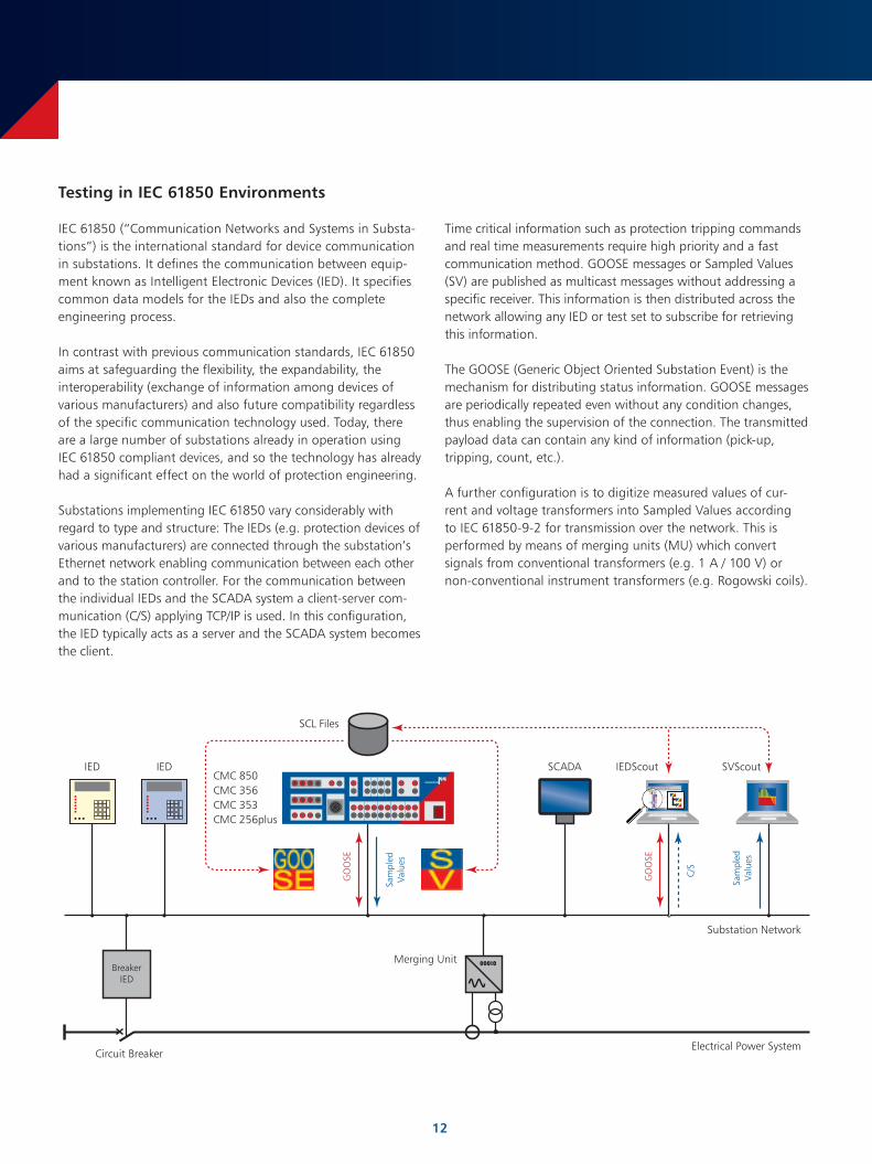
Substations implementing IEC 61850 vary considerably with regard to type and structure: The IEDs (e.g. protection devices of various manufacturers) are connected through the substation’s Ethernet network enabling communication between each other and to the station controller. For the communication between the individual IEDs and the SCADA system a client-server com-munication (C/S) applying TCP/IP is used. In this configuration, the IED typically acts as a server and the SCADA system becomes the client.
Time critical information such as protection tripping commands and real time measurements require high priority and a fast communication method. GOOSE messages or Sampled Values (SV) are published as multicast messages without addressing a specific receiver. This information is then distributed across the network allowing any IED or test set to subscribe for retrieving this information.
The GOOSE (Generic Object Oriented Substation Event) is the mechanism for distributing status information. GOOSE messages are periodically repeated even without any condition changes, thus enabling the supervision of the connection. The transmitted payload data can contain any kind of information (pick-up, tripping, count, etc.).
A further configuration is to digitize measured values of cur-rent and voltage transformers into Sampled Values according to IEC 61850-9-2 for transmission over the network. This is performed by means of merging units (MU) which convert signals from conventional transformers (e.g. 1 A / 100 V) or non-conventional instrument transformers (e.g. Rogowski coils).
00010
IED
Substation Network
Electrical Power System
IEDScoutSCADA
Merging UnitBreaker
IED
SCL Files
GO
OSE
Sam
pled
Valu
es
IED
Circuit Breaker
SVScout
Sam
pled
Valu
es
GO
OSE
C/S
CMC 850CMC 356CMC 353CMC 256plus
13
Most IEDs contain data models consisting of the elements described in IEC 61850, these are the standardized Logical Nodes (LN) and the data classes contained within them. Various services, such as a report to a client or the GOOSE utilize data sets based on that data model.
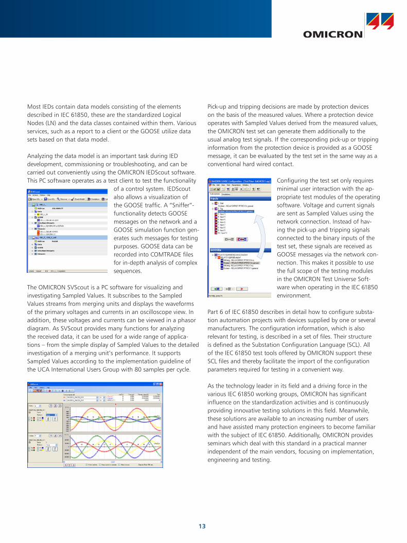
Analyzing the data model is an important task during IED development, commissioning or troubleshooting, and can be carried out conveniently using the OMICRON IEDScout software. This PC software operates as a test client to test the functionality
of a control system. IEDScout also allows a visualization of the GOOSE traffic. A “Sniffer”-functionality detects GOOSE messages on the network and a GOOSE simulation function gen-erates such messages for testing purposes. GOOSE data can be recorded into COMTRADE files for in-depth analysis of complex sequences.
The OMICRON SVScout is a PC software for visualizing and investigating Sampled Values. It subscribes to the Sampled Values streams from merging units and displays the waveforms of the primary voltages and currents in an oscilloscope view. In addition, these voltages and currents can be viewed in a phasor diagram. As SVScout provides many functions for analyzing the received data, it can be used for a wide range of applica-tions – from the simple display of Sampled Values to the detailed investigation of a merging unit’s performance. It supports Sampled Values according to the implementation guideline of the UCA International Users Group with 80 samples per cycle.
Pick-up and tripping decisions are made by protection devices on the basis of the measured values. Where a protection device operates with Sampled Values derived from the measured values, the OMICRON test set can generate them additionally to the usual analog test signals. If the corresponding pick-up or tripping information from the protection device is provided as a GOOSE message, it can be evaluated by the test set in the same way as a conventional hard wired contact.
Configuring the test set only requires minimal user interaction with the ap-propriate test modules of the operating software. Voltage and current signals are sent as Sampled Values using the network connection. Instead of hav-ing the pick-up and tripping signals connected to the binary inputs of the test set, these signals are received as GOOSE messages via the network con-nection. This makes it possible to use the full scope of the testing modules in the OMICRON Test Universe Soft-ware when operating in the IEC 61850 environment.
Part 6 of IEC 61850 describes in detail how to configure substa-tion automation projects with devices supplied by one or several manufacturers. The configuration information, which is also relevant for testing, is described in a set of files. Their structure is defined as the Substation Configuration Language (SCL). All of the IEC 61850 test tools offered by OMICRON support these SCL files and thereby facilitate the import of the configuration parameters required for testing in a convenient way.
As the technology leader in its field and a driving force in the various IEC 61850 working groups, OMICRON has significant influence on the standardization activities and is continuously providing innovative testing solutions in this field. Meanwhile, these solutions are available to an increasing number of users and have assisted many protection engineers to become familiar with the subject of IEC 61850. Additionally, OMICRON provides seminars which deal with this standard in a practical manner independent of the main vendors, focusing on implementation, engineering and testing.
14
Network Simulation with NetSim
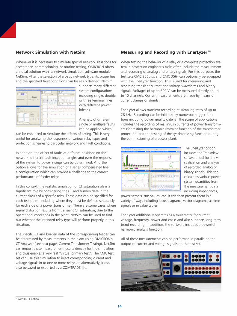
Whenever it is necessary to simulate special network situations for acceptance, commissioning, or routine testing, OMICRON offers an ideal solution with its network simulation software module NetSim. After the selection of a basic network type, its properties and the specified fault conditions can be easily defined. NetSim
supports many different system configurations including single, double or three terminal lines with different power infeeds.
A variety of different single or multiple faults can be applied which
can be enhanced to simulate the effects of arcing. This is very useful for analyzing the responses of various relay types and protection schemes to particular network and fault conditions.
In addition, the effect of faults at different positions on the network, different fault inception angles and even the response of the system to power swings can be determined. A further option allows for the simulation of a series compensated line, a configuration which can provide a challenge to the correct performance of feeder relays.
In this context, the realistic simulation of CT saturation plays a significant role by considering the CT and burden data in the current circuit of a specific relay. These data can be specified for each test point, including where they must be defined separately for each side of a power transformer. There are some cases where signal distortion results from transient CT saturation, due to the operational conditions in the plant. NetSim can be used to find out whether the intended relay type will perform properly in this situation.
The specific CT and burden data of the corresponding feeder can be determined by measurements in the plant using OMICRON’s CT Analyzer (see next page: Current Transformer Testing). NetSim can import these measurement results directly for the simulation and thus enables a very fast “virtual primary test”. The CMC test set can use this simulation to inject corresponding current and voltage signals in to one or more relays or, alternatively, it can also be saved or exported as a COMTRADE file.
Measuring and Recording with EnerLyzer™
When testing the behavior of a relay or a complete protection sys-tem, a protection engineer’s tasks often include the measurement and recording of analog and binary signals. For this purpose, the test sets CMC 256plus and CMC 356 2 can optionally be equipped with the EnerLyzer function. This is used for measuring and recording transient current and voltage waveforms and binary signals. Voltages of up to 600 V can be measured directly on up to 10 channels. Current measurements are made by means of current clamps or shunts.
EnerLyzer allows transient recording at sampling rates of up to 28 kHz. Recording can be initiated by numerous trigger func-tions including power quality criteria. The scope of applications includes the recording of real inrush currents of power transform-ers (for testing the harmonic restraint function of the transformer protection) and the testing of the synchronizing function during the commissioning of a power plant.
The EnerLyzer option includes the TransView software tool for the vi-sualization and analysis of recorded analog or binary signals. This tool calculates various power system quantities from the measurement data including impedances,
power vectors, rms values, etc. It can then present them in a variety of ways including locus diagrams, vector diagrams, as time signals or in value tables.
EnerLyzer additionally operates as a multimeter for current, voltage, frequency, power and cos ϕ and also supports long-term trend recording. In addition, the software includes a powerful harmonic analysis function.
All of these measurements can be performed in parallel to the output of current and voltage signals on the test set.
2 With ELT-1 option

15
Line Impedance Measurement and k-Factor Determination
For the correct setting of a distance protection relay, the values of the positive and zero sequence impedance of the line to be protected are of utmost importance. Incorrect values lead to zone over- or under-reaching which in turn could cause the incorrect operation of the relay under fault conditions. Proper settings allow selective tripping, minimum fault duration times and ensure that the relay’s fault location functionality can be utilized to its full extend.
The impedances and the k-factor (residual compensation factor) are usually calculated using a network simulation program or are the results of a systems study. The calculations however are very prone to errors due to the large number of influencing factors (e.g. conductor type, spiraling and average sag of the lines, cable shield handling, specific soil resistivity etc.). Therefore, actual measurement of the fault-loop impedance is the best way to ensure that the distance protection relay settings are correct.
For this task the OMICRON CPC 100 and the CP CU1 are used together. The ability of the CPC 100 to operation away from the line frequency range overcomes the problem of power system frequency interference that has previously made it necessary to use extremely large, high-power equipment to carry out these measurements. This system allows the user to measure the im-pedance of all fault loops (phase-to-ground, phase-to-phase and three-phase-to-ground) with compact and portable equipment.
Current Transformer Testing
The parameters of current transformers have a direct influence on the reliability of the protection system. With the CT Analyzer, OMICRON offers a unique solution for the efficient determination of the essential CT parameters including CT ratio, phase and cur-rent ratio errors for different burden values, the excitation curve, winding resistance, transient behavior and many others. Due to its small size, low weight and its high precision it is the perfect tool for CT testing both at the CT manufacturers’ premises as well as on-site. The patented 3 measurement method allows very quick automated testing and reporting while ensuring the maximum level of operator safety.For more information please refer to the “CT Analyzer” brochure (see last page).
Coupling Impedance Measurement of Parallel Systems
Distance protection relays protecting one of two parallel lines often compensate for induced currents between the two systems. The setting required for this is the so-called Mutual Coupling factor. This can be determined in the same way as the k-factor using the combination of the CPC 100 and CP CU1.
For more information about the CPC 100 and CP CU1 combina-tion, please refer to the brochure “CP CU1 – Multifunctional Coupling Unit for CPC 100” (see last page).
3 EP1653238 B1, EP1398644 B1, US6987390 B2
© OMICRON L206, September 2011Subject to change without notice www.omicron.at • www.omicronusa.com
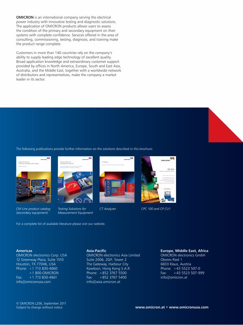
CM Line product catalog (secondary equipment)
Testing Solutions for Measurement Equipment
CT Analyzer CPC 100 and CP CU1
The following publications provide further information on the solutions described in this brochure:
Testing Solutions for Protection and Measurement Systems
PRODUCT CATALOG
Mea su r emen t S y s t em f o r
Multi-purpose coupling unit for CPC 100
CP Cu1
Line Impedances and k-Factors
Mutual Coupling of Parallel Lines
Ground Impedances of Large Substations
Step and Touch Voltages
Coupling of Power Lines into Signal Cables
Variable Frequency
CT Analyzer
Revolution in Current Transformer Testing and Calibration
Testing Solutions for Measurement Equipment
Power Quality Measurement Devices • Electricity Meters Measuring Transducers • Equipment Calibration
AmericasOMICRON electronics Corp. USA12 Greenway Plaza, Suite 1510Houston, TX 77046, USAPhone: +1 713 830-4660 +1 800-OMICRONFax: +1 713 [email protected]
Asia-PacificOMICRON electronics Asia LimitedSuite 2006, 20/F, Tower 2The Gateway, Harbour CityKowloon, Hong Kong S.A.R.Phone: +852 3767 5500Fax: +852 3767 [email protected]
Europe, Middle East, AfricaOMICRON electronics GmbHOberes Ried 16833 Klaus, AustriaPhone: +43 5523 507-0Fax: +43 5523 [email protected]
For a complete list of available literature please visit our website.
OMICRON is an international company serving the electrical power industry with innovative testing and diagnostic solutions. The application of OMICRON products allows users to assess the condition of the primary and secondary equipment on their systems with complete confidence. Services offered in the area of consulting, commissioning, testing, diagnosis, and training make the product range complete.
Customers in more than 140 countries rely on the company’s ability to supply leading edge technology of excellent quality. Broad application knowledge and extraordinary customer support provided by offices in North America, Europe, South and East Asia, Australia, and the Middle East, together with a worldwide network of distributors and representatives, make the company a market leader in its sector.