Embed Size (px)
Citation preview
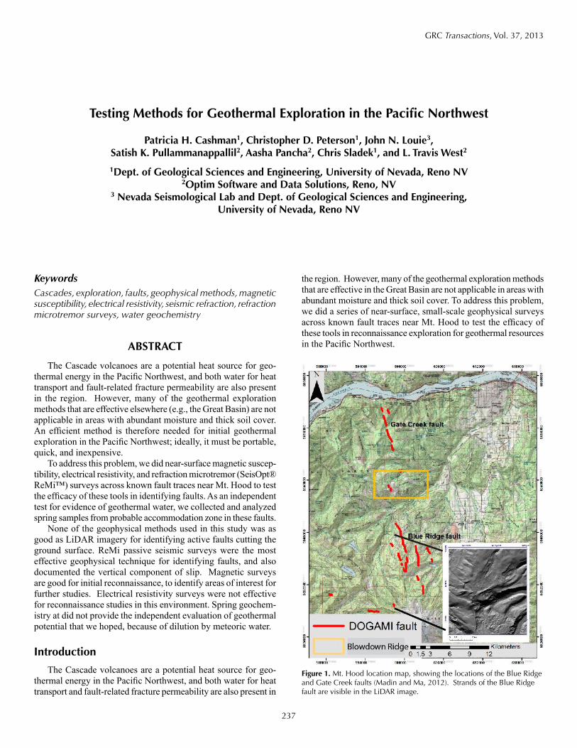
GRC Transactions, Vol. 37, 2013
237
KeywordsCascades, exploration, faults, geophysical methods, magnetic susceptibility, electrical resistivity, seismic refraction, refraction microtremor surveys, water geochemistry
ABSTRACT
The Cascade volcanoes are a potential heat source for geo-thermal energy in the Pacific Northwest, and both water for heat transport and fault-related fracture permeability are also present in the region. However, many of the geothermal exploration methods that are effective elsewhere (e.g., the Great Basin) are not applicable in areas with abundant moisture and thick soil cover. An efficient method is therefore needed for initial geothermal exploration in the Pacific Northwest; ideally, it must be portable, quick, and inexpensive.
To address this problem, we did near-surface magnetic suscep-tibility, electrical resistivity, and refraction microtremor (SeisOpt® ReMi™) surveys across known fault traces near Mt. Hood to test the efficacy of these tools in identifying faults. As an independent test for evidence of geothermal water, we collected and analyzed spring samples from probable accommodation zone in these faults.
None of the geophysical methods used in this study was as good as LiDAR imagery for identifying active faults cutting the ground surface. ReMi passive seismic surveys were the most effective geophysical technique for identifying faults, and also documented the vertical component of slip. Magnetic surveys are good for initial reconnaissance, to identify areas of interest for further studies. Electrical resistivity surveys were not effective for reconnaissance studies in this environment. Spring geochem-istry at did not provide the independent evaluation of geothermal potential that we hoped, because of dilution by meteoric water.
Introduction
The Cascade volcanoes are a potential heat source for geo-thermal energy in the Pacific Northwest, and both water for heat transport and fault-related fracture permeability are also present in
the region. However, many of the geothermal exploration methods that are effective in the Great Basin are not applicable in areas with abundant moisture and thick soil cover. To address this problem, we did a series of near-surface, small-scale geophysical surveys across known fault traces near Mt. Hood to test the efficacy of these tools in reconnaissance exploration for geothermal resources in the Pacific Northwest.
Testing Methods for Geothermal Exploration in the Pacific Northwest
Patricia H. Cashman1, Christopher D. Peterson1, John N. Louie3, Satish K. Pullammanappallil2, Aasha Pancha2, Chris Sladek1, and L. Travis West2
1Dept. of Geological Sciences and Engineering, University of Nevada, Reno NV2Optim Software and Data Solutions, Reno, NV
3 Nevada Seismological Lab and Dept. of Geological Sciences and Engineering, University of Nevada, Reno NV
Figure 1. Mt. Hood location map, showing the locations of the Blue Ridge and Gate Creek faults (Madin and Ma, 2012). Strands of the Blue Ridge fault are visible in the LiDAR image.
238
Cashman, et al.
The study area, on the north flank of Mt. Hood, has several characteristics favorable for geothermal potential: proximity to an active volcanic heat source, active faults, and a zone that could be favorable for the upwelling of geothermal fluids. The study area includes parts of two active normal fault systems recently identified on LiDAR imagery, the west-dipping Blue Ridge fault and the east-dipping Gate Creek fault (Madin and Ma, 2012) (Fig. 1). Blowdown Ridge, along strike north of the Blue Ridge fault and south of the Gate Creek fault, is a prob-able accommodation zone between the two. Accommodation zones typically have pervasive fracturing associated with the terminations of the two fault systems; this fracture permeability can be favorable for the development of geothermal systems (e.g., Faulds, 2004, 2006, 2011). Blowdown Ridge is also a topographic high, isolated from glacial meltwater derived from Mt. Hood. Finally, existing roads provide relatively good ac-cess to the fault scarps as well as cleared space for survey lines through the typically thick vegetation.
We ran geophysical survey lines across the known faults, to establish the fault signature, if present, with each method. The shallow geophysical methods -- magnetic susceptibility, electri-cal resistivity, and refraction microtremor (SeisOpt® ReMi™) surveys -- are fast and relatively inexpensive, and therefore ap-propriate for use as reconnaissance exploration tools. We then did magnetic surveys across parts of the accommodation zone where no faults are mapped. As an independent test for evidence of geothermal water, we collected and analyzed spring samples from Blowdown Ridge, the topographic high and probable ac-commodation zone between the two fault sets.
In this paper, we summarize the structural setting of the Blue Ridge and Gate Creek faults, and then briefly describe the geo-physical methods used in the study. We report the results from magnetic, resistivity, and seismic velocity surveys across known fault traces. We identify anomalies associated with the faults, and compare the geologic information gleaned from the differ-ent methods. We then summarize the spring geochemistry data and conclude with a discussion of implications of the results for geothermal resource exploration in the Pacific Northwest.
BackgroundGeologic Setting
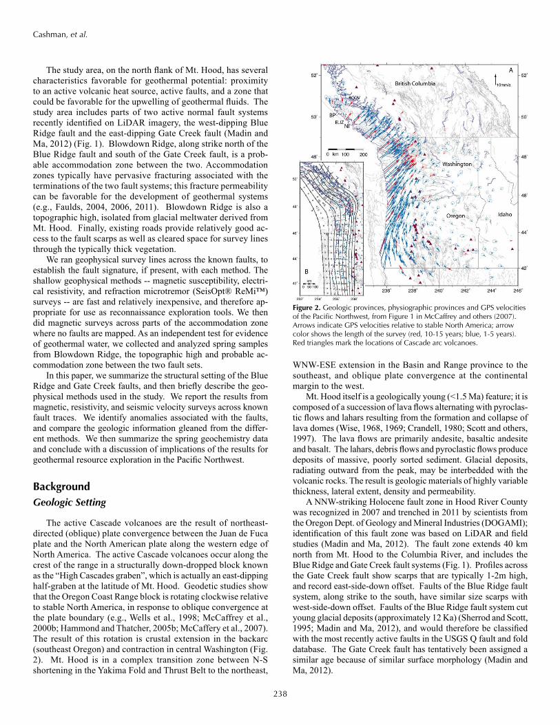
The active Cascade volcanoes are the result of northeast-directed (oblique) plate convergence between the Juan de Fuca plate and the North American plate along the western edge of North America. The active Cascade volcanoes occur along the crest of the range in a structurally down-dropped block known as the “High Cascades graben”, which is actually an east-dipping half-graben at the latitude of Mt. Hood. Geodetic studies show that the Oregon Coast Range block is rotating clockwise relative to stable North America, in response to oblique convergence at the plate boundary (e.g., Wells et al., 1998; McCaffrey et al., 2000b; Hammond and Thatcher, 2005b; McCaffery et al., 2007). The result of this rotation is crustal extension in the backarc (southeast Oregon) and contraction in central Washington (Fig. 2). Mt. Hood is in a complex transition zone between N-S shortening in the Yakima Fold and Thrust Belt to the northeast,
WNW-ESE extension in the Basin and Range province to the southeast, and oblique plate convergence at the continental margin to the west.
Mt. Hood itself is a geologically young (<1.5 Ma) feature; it is composed of a succession of lava flows alternating with pyroclas-tic flows and lahars resulting from the formation and collapse of lava domes (Wise, 1968, 1969; Crandell, 1980; Scott and others, 1997). The lava flows are primarily andesite, basaltic andesite and basalt. The lahars, debris flows and pyroclastic flows produce deposits of massive, poorly sorted sediment. Glacial deposits, radiating outward from the peak, may be interbedded with the volcanic rocks. The result is geologic materials of highly variable thickness, lateral extent, density and permeability.
A NNW-striking Holocene fault zone in Hood River County was recognized in 2007 and trenched in 2011 by scientists from the Oregon Dept. of Geology and Mineral Industries (DOGAMI); identification of this fault zone was based on LiDAR and field studies (Madin and Ma, 2012). The fault zone extends 40 km north from Mt. Hood to the Columbia River, and includes the Blue Ridge and Gate Creek fault systems (Fig. 1). Profiles across the Gate Creek fault show scarps that are typically 1-2m high, and record east-side-down offset. Faults of the Blue Ridge fault system, along strike to the south, have similar size scarps with west-side-down offset. Faults of the Blue Ridge fault system cut young glacial deposits (approximately 12 Ka) (Sherrod and Scott, 1995; Madin and Ma, 2012), and would therefore be classified with the most recently active faults in the USGS Q fault and fold database. The Gate Creek fault has tentatively been assigned a similar age because of similar surface morphology (Madin and Ma, 2012).
Figure 2. Geologic provinces, physiographic provinces and GPS velocities of the Pacific Northwest, from Figure 1 in McCaffrey and others (2007). Arrows indicate GPS velocities relative to stable North America; arrow color shows the length of the survey (red, 10-15 years; blue, 1-5 years). Red triangles mark the locations of Cascade arc volcanoes.
239
Cashman, et al.
Choice of Exploration ToolsMany of the exploration methods that are effective in the Great
Basin (e.g., geologic field mapping, structural analysis, or shallow temperature surveys) are not applicable in the Cascades. The ter-rain is often steep and densely wooded. Bedrock exposures are rare, and exposures of faults with kinematic data are rarer. Shal-low temperature methods sample only the top 2m of soil; this is not enough to get past the abundant meteoric water that can mask geothermal signals.
Active faults, which can provide the permeability for geo-thermal fluids to reach the surface, are easily recognizable on LiDAR imagery in a heavily vegetated environment. However, LiDAR imagery is not available everywhere and is expensive to acquire, prompting this test of reconnaissance geophysical tools as a potential alternative.
Spring geochemistry is a reliable detector of high-temperature water at depth, but sampling springs for geochemical analyses is time-consuming and costly; it is not a practical reconnaissance exploration tool. Water chemistry retains a record of high tem-perature at depth, because some minerals dissolve only at high temperatures. This method can therefore identify presence of hot water, but not its source. An additional problem is that water temperature measured at springs can be strongly influenced by rainwater and meltwater, so any geothermal signal may be masked. However, in a study at Mt. Hood, Nathenson (2004) confirmed the presence of geothermal water. He also found springs that are not mapped, usually where creeks start, and suggested there are more unmapped springs.
This study was therefore designed to test three reconnais-sance geophysical tools at the study area on the north flank of Mt. Hood. We started with surveys across known fault traces in the Blue Ridge and Gate Creek fault systems (Fig. 1), to identify any shallow magnetic, resistivity, or velocity anomalies associated with the faults. In some environments, a combination of ground-magnetic and shallow electrical resistivity surveys can locate and characterize near-surface fault traces (Shields et al., 1998). SeisOpt® ReMi™ surveys, in their normal shallow geotechnical mode, have also been able to identify the fractured areas around fault traces (Scott et al., 2006). After surveying across known faults, we then ran two magnetic surveys on Blowdown Ridge, in the apparent accommodation zone between the Blue Ridge fault and the Gate Creek fault, to see whether we could identify previ-ously unmapped faults. All traverses were along logging roads, for easy access and efficient data collection. As an independent test of geothermal potential, we sampled the springs at Blowdown Ridge, and analyzed the samples for geochemical evidence of high-temperature water at depth.
Methods
All data were collected using standard sampling methods. The geophysical surveys were done according to the techniques already developed by Louie and by Optim, the collaborating geophysical exploration company on this project. Water samples were analyzed at the University of Nevada, Reno laboratories.
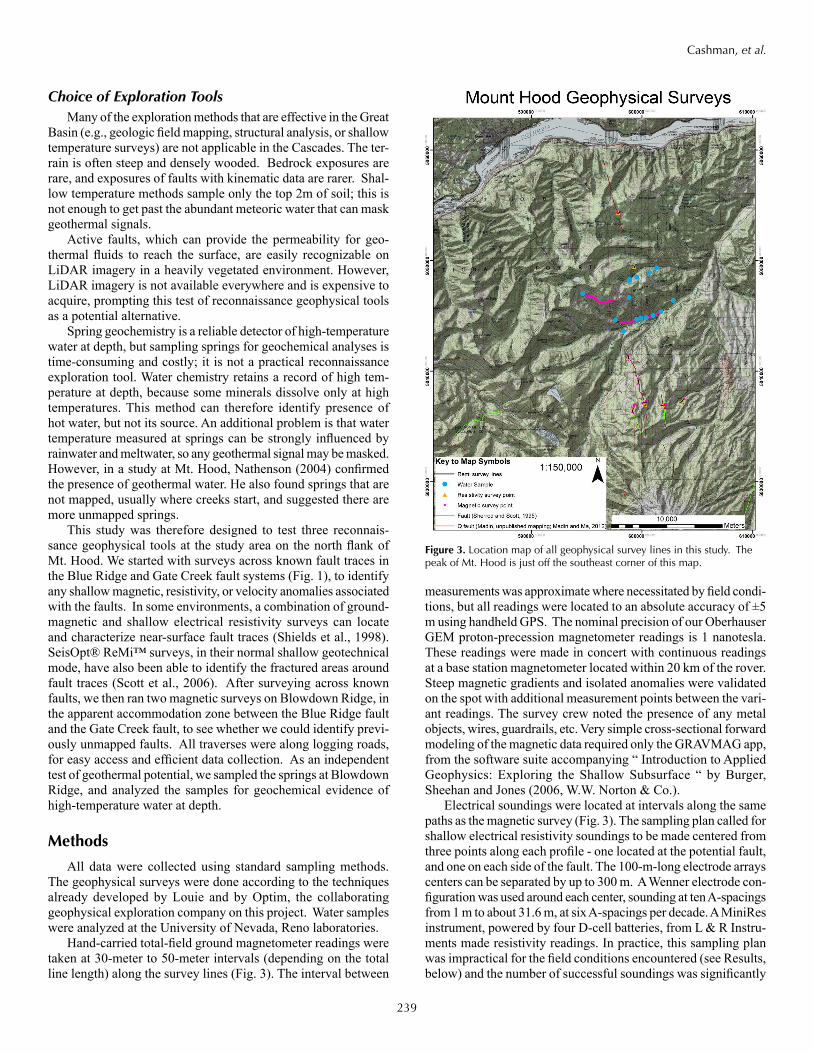
Hand-carried total-field ground magnetometer readings were taken at 30-meter to 50-meter intervals (depending on the total line length) along the survey lines (Fig. 3). The interval between
measurements was approximate where necessitated by field condi-tions, but all readings were located to an absolute accuracy of ±5 m using handheld GPS. The nominal precision of our Oberhauser GEM proton-precession magnetometer readings is 1 nanotesla. These readings were made in concert with continuous readings at a base station magnetometer located within 20 km of the rover. Steep magnetic gradients and isolated anomalies were validated on the spot with additional measurement points between the vari-ant readings. The survey crew noted the presence of any metal objects, wires, guardrails, etc. Very simple cross-sectional forward modeling of the magnetic data required only the GRAVMAG app, from the software suite accompanying “ Introduction to Applied Geophysics: Exploring the Shallow Subsurface “ by Burger, Sheehan and Jones (2006, W.W. Norton & Co.).
Electrical soundings were located at intervals along the same paths as the magnetic survey (Fig. 3). The sampling plan called for shallow electrical resistivity soundings to be made centered from three points along each profile - one located at the potential fault, and one on each side of the fault. The 100-m-long electrode arrays centers can be separated by up to 300 m. A Wenner electrode con-figuration was used around each center, sounding at ten A-spacings from 1 m to about 31.6 m, at six A-spacings per decade. A MiniRes instrument, powered by four D-cell batteries, from L & R Instru-ments made resistivity readings. In practice, this sampling plan was impractical for the field conditions encountered (see Results, below) and the number of successful soundings was significantly
Figure 3. Location map of all geophysical survey lines in this study. The peak of Mt. Hood is just off the southeast corner of this map.
240
Cashman, et al.
smaller than originally intended. Resistivity versus depth profiles were very simply modeled from the apparent-resistivity soundings withthe RESIST app, again from the software suite accompanying Burger, Sheehan and Jones ( 2006, W.W. Norton & Co.). Since the electrical arrays were so simple and data are relatively sparse, more advanced modeling would not be justified.
Shallow SeisOpt® ReMi™ refraction microtremor arrays were co-located with the electrical arrays, along the magnetic survey lines (Fig. 3) and consisted of a 24-channel or, more commonly, 48-channel array of 4.5-Hz geophones spaced at 8 m. Each ar-ray placement collected several ambient noise records, including sledgehammer hits as needed. They were modeled for shear-wave seismic velocity versus depth profiles in accordance with standard industry practice (Louie, 2001). Aasha Pancha (Optim SDS) donated two-dimensional SeisOpt® ReMi™analysis of each array, resulting in a cross-section of shear velocities to a depth of approximately 100m.
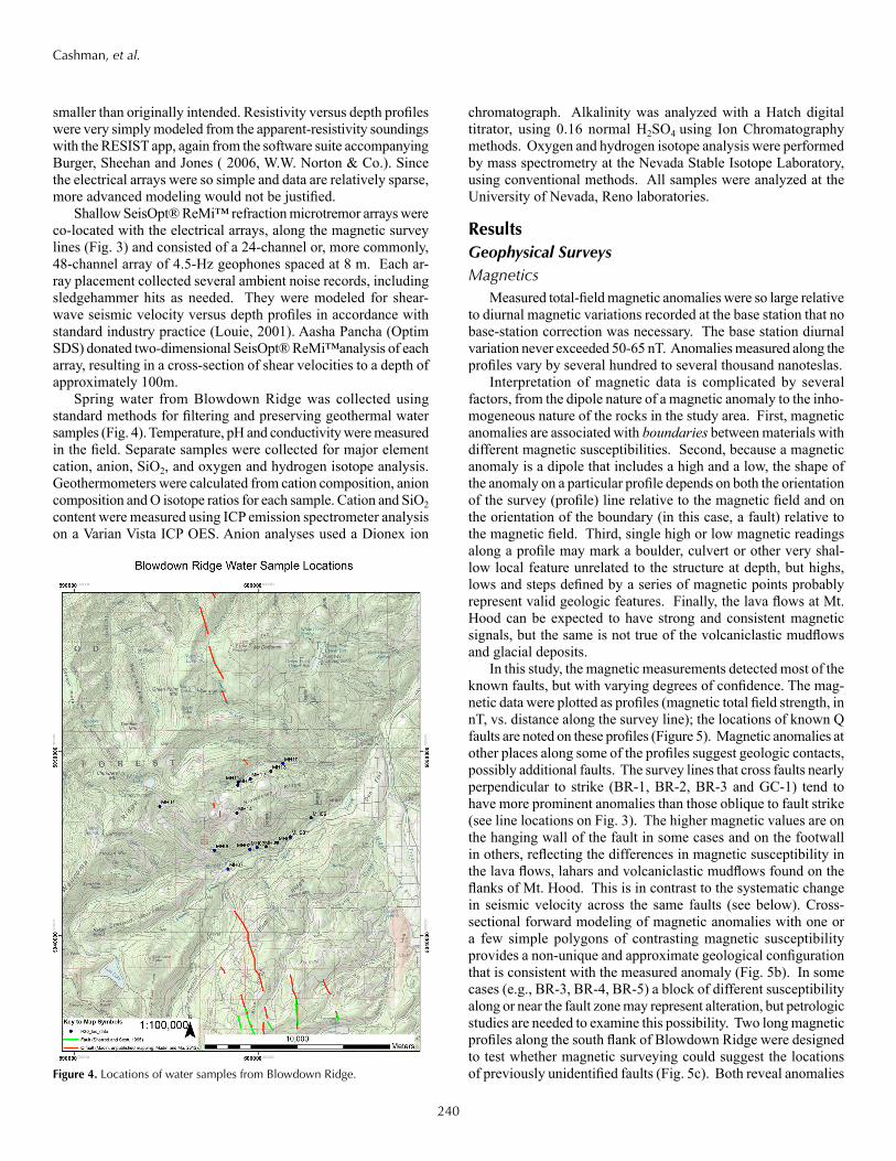
Spring water from Blowdown Ridge was collected using standard methods for filtering and preserving geothermal water samples (Fig. 4). Temperature, pH and conductivity were measured in the field. Separate samples were collected for major element cation, anion, SiO2, and oxygen and hydrogen isotope analysis. Geothermometers were calculated from cation composition, anion composition and O isotope ratios for each sample. Cation and SiO2 content were measured using ICP emission spectrometer analysis on a Varian Vista ICP OES. Anion analyses used a Dionex ion
chromatograph. Alkalinity was analyzed with a Hatch digital titrator, using 0.16 normal H2SO4 using Ion Chromatography methods. Oxygen and hydrogen isotope analysis were performed by mass spectrometry at the Nevada Stable Isotope Laboratory, using conventional methods. All samples were analyzed at the University of Nevada, Reno laboratories.
ResultsGeophysical SurveysMagnetics
Measured total-field magnetic anomalies were so large relative to diurnal magnetic variations recorded at the base station that no base-station correction was necessary. The base station diurnal variation never exceeded 50-65 nT. Anomalies measured along the profiles vary by several hundred to several thousand nanoteslas.
Interpretation of magnetic data is complicated by several factors, from the dipole nature of a magnetic anomaly to the inho-mogeneous nature of the rocks in the study area. First, magnetic anomalies are associated with boundariesbetween materials with different magnetic susceptibilities. Second, because a magnetic anomaly is a dipole that includes a high and a low, the shape of the anomaly on a particular profile depends on both the orientation of the survey (profile) line relative to the magnetic field and on the orientation of the boundary (in this case, a fault) relative to the magnetic field. Third, single high or low magnetic readings along a profile may mark a boulder, culvert or other very shal-low local feature unrelated to the structure at depth, but highs, lows and steps defined by a series of magnetic points probably represent valid geologic features. Finally, the lava flows at Mt. Hood can be expected to have strong and consistent magnetic signals, but the same is not true of the volcaniclastic mudflows and glacial deposits.
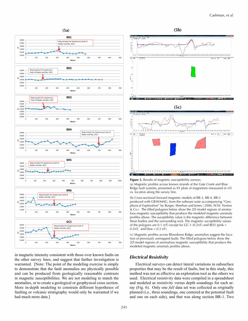
In this study, the magnetic measurements detected most of the known faults, but with varying degrees of confidence. The mag-netic data were plotted as profiles (magnetic total field strength, in nT, vs. distance along the survey line); the locations of known Q faults are noted on these profiles (Figure 5). Magnetic anomalies at other places along some of the profiles suggest geologic contacts, possibly additional faults. The survey lines that cross faults nearly perpendicular to strike (BR-1, BR-2, BR-3 and GC-1) tend to have more prominent anomalies than those oblique to fault strike (see line locations on Fig. 3). The higher magnetic values are on the hanging wall of the fault in some cases and on the footwall in others, reflecting the differences in magnetic susceptibility in the lava flows, lahars and volcaniclastic mudflows found on the flanks of Mt. Hood. This is in contrast to the systematic change in seismic velocity across the same faults (see below). Cross-sectional forward modeling of magnetic anomalies with one or a few simple polygons of contrasting magnetic susceptibility provides a non-unique and approximate geological configuration that is consistent with the measured anomaly (Fig. 5b). In some cases (e.g., BR-3, BR-4, BR-5) a block of different susceptibility along or near the fault zone may represent alteration, but petrologic studies are needed to examine this possibility. Two long magnetic profiles along the south flank of Blowdown Ridge were designed to test whether magnetic surveying could suggest the locations of previously unidentified faults (Fig. 5c). Both reveal anomalies Figure 4. Locations of water samples from Blowdown Ridge.
241
Cashman, et al.
in magnetic intensity consistent with those over known faults on the other survey lines, and suggest that further investigation is warranted. [Note: The point of the modeling exercise is simply to demonstrate that the fault anomalies are physically possible and can be produced from geologically reasonable contrasts in magnetic susceptibilities. We are not modeling to match the anomalies, or to create a geological or geophysical cross section. More in-depth modeling to constrain different hypotheses of faulting or volcanic stratigraphy would only be warranted if we had much more data.]
Electrical Resistivity
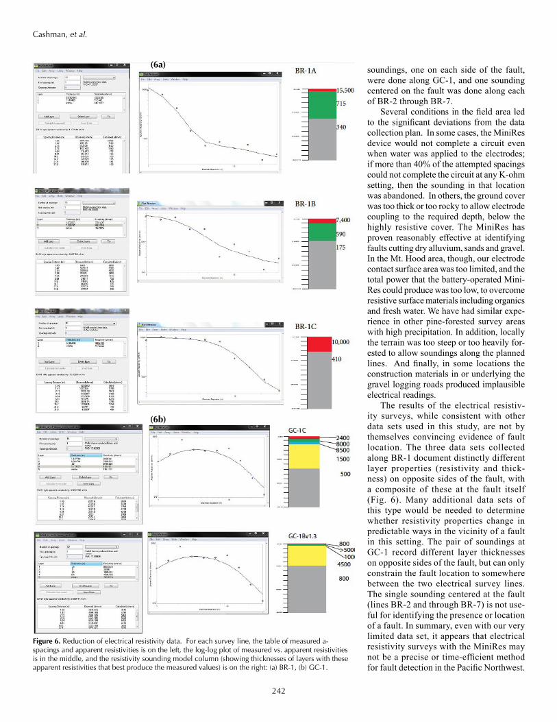
Electrical surveys can detect lateral variations in subsurface properties that may be the result of faults, but in this study, this method was not as effective an exploration tool as the others we used. Electrical resistivity data were compiled in a spreadsheet and modeled as resistivity versus depth soundings for each ar-ray (Fig. 6). Only one full data set was collected as originally planned (i.e., three soundings, one centered at the potential fault and one on each side), and that was along section BR-1. Two
Figure 5. Results of magnetic susceptibility surveys.(a) Magnetic profiles across known strands of the Gate Creek and Blue Ridge fault systems, presented as XY plots of magnetism (measured in nT) vs. location along the survey line.
(b) Cross-sectional forward magnetic models of BR-3, BR-4, BR-5 produced with GRAVMAG, from the software suite accompanying “Geo-physical Exploration” by Burger, Sheehan and Jones ( 2006, W.W. Norton & Co.). The filled polygons below show the 2D model regions of anoma-lous magnetic susceptibility that produce the modeled magnetic-anomaly profiles above. The suceptibility value is the magnetic difference between these bodies and the surrounding rock. The magnetic suceptibility values of the polygons are 0.1 (nT) except for GC-1 (0.2nT) and BD3 (pink = 0.2nT; and blue = 0.3 nT).
(c) Magnetic profiles across Blowdown Ridge; anomalies suggest the loca-tion of previously unmapped faults. The filled polygons below show the 2D model regions of anomalous magnetic susceptibility that produce the modeled magnetic-anomaly profiles above.
51000
52000
53000
54000
55000
56000
0 100 200 300 400 500 600 700 800 900
nT
Meters
BR1
Map location for Quaternary Fault of Madin and Ma, 2012
51000
52000
53000
54000
55000
56000
0 100 200 300 400 500 600 700 800 900
nT
Meters
BR2 Map location for Quaternary Fault of Madin and Ma, 2012
50000510005200053000540005500056000
0 100 200 300 400 500 600 700 800 900
nT
Meters
BR3 Map location for Quaternary Fault of Madin and Ma, 2012
51000
52000
53000
54000
55000
56000
0 100 200 300 400 500 600 700 800 900
nT
Meters
BR4 Map location for Quaternary Fault of Madin and Ma, 2012
51000
52000
53000
54000
55000
56000
0 100 200 300 400 500 600 700 800 900 1000
nT
Meters
BR5 Map location for Quaternary Fault of Madin and Ma, 2012
51000
52000
53000
54000
55000
56000
0 100 200 300 400 500 600 700 800 900
nT
Meters
BR6 Map location for Quaternary Fault of Madin and Ma, 2012
51000
52000
53000
54000
55000
56000
0 100 200 300 400 500 600 700 800 900
nT
Meters
GC1 Map location for Quaternary Fault of Madin and Ma, 2012
(5a) (5b)
(5c)
242
Cashman, et al.
soundings, one on each side of the fault, were done along GC-1, and one sounding centered on the fault was done along each of BR-2 throughBR-7.
Several conditions in the field area led to the significant deviations from the data collection plan. In some cases, the MiniRes device would not complete a circuit even when water was applied to the electrodes; if more than 40% of the attempted spacings could not complete the circuit at any K-ohm setting, then the sounding in that location was abandoned. In others, the ground cover was too thick or too rocky to allow electrode coupling to the required depth, below the highly resistive cover. The MiniRes has proven reasonably effective at identifying faults cutting dry alluvium, sands and gravel. In the Mt. Hood area, though, our electrode contact surface area was too limited, and the total power that the battery-operated Mini-Res could produce was too low, to overcome resistive surface materials including organics and fresh water. We have had similar expe-rience in other pine-forested survey areas with high precipitation. In addition, locally the terrain was too steep or too heavily for-ested to allow soundings along the planned lines. And finally, in some locations the construction materials in or underlying the gravel logging roads produced implausible electrical readings.
The results of the electrical resistiv-ity surveys, while consistent with other data sets used in this study, are not by themselves convincing evidence of fault location. The three data sets collected along BR-1 document distinctly different layer properties (resistivity and thick-ness) on opposite sides of the fault, with a composite of these at the fault itself (Fig. 6). Many additional data sets of this type would be needed to determine whether resistivity properties change in predictable ways in the vicinity of a fault in this setting. The pair of soundings at GC-1 record different layer thicknesses on opposite sides of the fault, but can only constrain the fault location to somewhere between the two electrical survey lines. The single sounding centered at the fault (lines BR-2 and through BR-7) is not use-ful for identifying the presence or location of a fault. In summary, even with our very limited data set, it appears that electrical resistivity surveys with the MiniRes may not be a precise or time-efficient method for fault detection in the Pacific Northwest.
Figure 6. Reduction of electrical resistivity data. For each survey line, the table of measured a-spacings and apparent resistivities is on the left, the log-log plot of measured vs. apparent resistivities is in the middle, and the resistivity sounding model column (showing thicknesses of layers with these apparent resistivities that best produce the measured values) is on the right: (a) BR-1, (b) GC-1.
(6a)
(6b)
243
Cashman, et al.
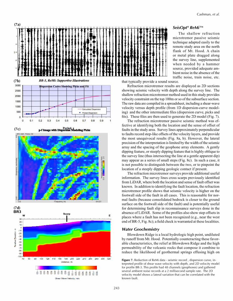
SeisOpt® ReMi™The shallow refraction
microtremor passive seismic technique adapted easily to the remote study area on the north flank of Mt. Hood. A chain or metal plate dragged along the survey line, supplemented when needed by a hammer source, provided adequate am-bient noise in the absence of the traffic noise, train noise, etc.
that typically provide a sound source.Refraction microtremor results are displayed as 2D sections
showing seismic velocity with depth along the survey line. The shallow refraction microtremor method used in this study provides velocity constraint on the top 100m or so of the subsurface section. The raw data are compiled in a spreadsheet, including a shear-wave velocity versus depth profile (from 1D dispersion-curve model-ing) and the other intermediate files (dispersion curve, picks and fits). These files are then used to generate the 2D model (Fig. 7).
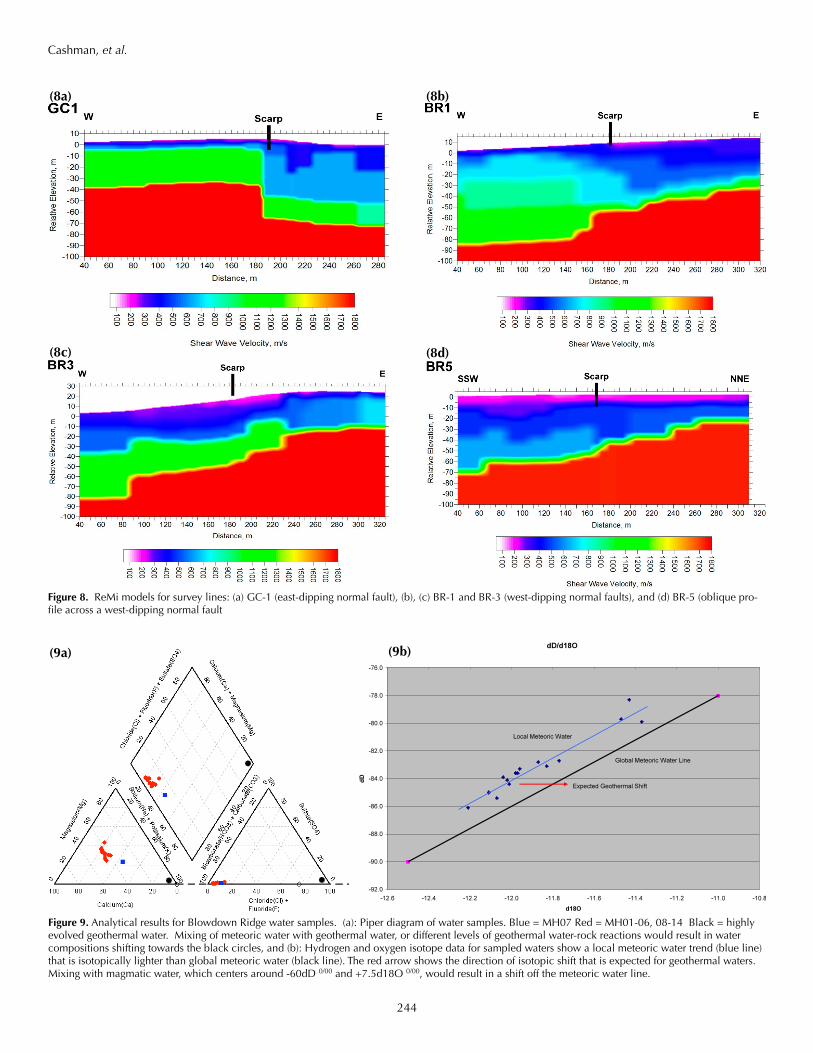
The refraction microtremor passive seismic method was ef-fective at identifying both the location and the sense of offset of faults in the study area. Survey lines approximately perpendicular to faults record step-like offsets of the velocity layers, and provide the most unequivocal results (Fig. 8a, b). However, the lateral precision of the interpretation is limited by the width of the seismic array and the spacing of the geophone array elements. A gently dipping feature, or steeply dipping feature that is highly oblique to the survey line (thus intersecting the line at a gentle apparent dip) may appear as a series of small steps (Fig. 8c). In such a case, it is not possible to distinguish between the two, or to pinpoint the location of a steeply dipping geologic contact if present.
The refraction microtremor surveys provide additional useful information. The survey lines cross scarps previously identified from LiDAR, where both the location and sense of fault offset was known. In addition to identifying the fault location, the refraction microtremor profile shows that seismic velocity is higher on the footwall side of the fault in all cases. This is reasonable for nor-mal faults (because consolidated bedrock is closer to the ground surface on the footwall side of the fault) and is potentially useful for determining fault slip in reconnaissance surveys done in the absence of LiDAR. Some of the profiles also show step offsets in places where a fault has not been recognized (e.g., near the west end of BR-5, Fig. 8c); a field check is warranted at these localities.
Water GeochemistryBlowdown Ridge is a local hydrologic high point, undiluted
by runoff from Mt. Hood. Potentially counteracting these favor-able characteristics, the relief at Blowdown Ridge and the high permeability of the volcanic rocks that compose it combine to reduce the likelihood of geothermal springs effusing high on
Figure 7. Reduction of ReMi data - seismic record , dispersion curve, in-terpreted profile of shear wave velocity with depth, and 2D velocity model for profile BR-3. This profile had 48 channels (geophones) and gathered several ambient noise records at a 2 millisecond sample rate. The 2D velocity model shows a lateral variation that can be correlated with the known fault.
(7b)
(7a)
(7c)
(7d)
244
Cashman, et al.
Figure 8. ReMi models for survey lines: (a) GC-1 (east-dipping normal fault), (b), (c) BR-1 and BR-3 (west-dipping normal faults), and (d) BR-5 (oblique pro-file across a west-dipping normal fault
(8a) (8b)
(8c) (8d)
!
(9a)!
(9b)
Figure 9. Analytical results for Blowdown Ridge water samples. (a): Piper diagram of water samples. Blue = MH07 Red = MH01-06, 08-14 Black = highly evolved geothermal water. Mixing of meteoric water with geothermal water, or different levels of geothermal water-rock reactions would result in water compositions shifting towards the black circles, and (b): Hydrogen and oxygen isotope data for sampled waters show a local meteoric water trend (blue line) that is isotopically lighter than global meteoric water (black line). The red arrow shows the direction of isotopic shift that is expected for geothermal waters. Mixing with magmatic water, which centers around -60dD 0/00 and +7.5d18O 0/00, would result in a shift off the meteoric water line.
245
Cashman, et al.
##
598000.000000
598000.000000
5054
000.0
0000
0
5054
000.0
0000
0
1,000
Key to Map SymbolsRemi survey lines
# Resistivity survey pointFault (Sherrod and Scott, 1995)
Q fault (Madin, unpublished mapping; Madin and Ma, 2012)
BR1$ Events
Meters
0 m
10m
20m
30 m
GC-1Bv1.3GC-1C2400800085001500
500
0 m
30 m
10m
20m
800>5000
10004500
800
0 m
30 m
10m
20m
0 m
30 m
10m
20m
EW
LiDAR mapped fault scarp
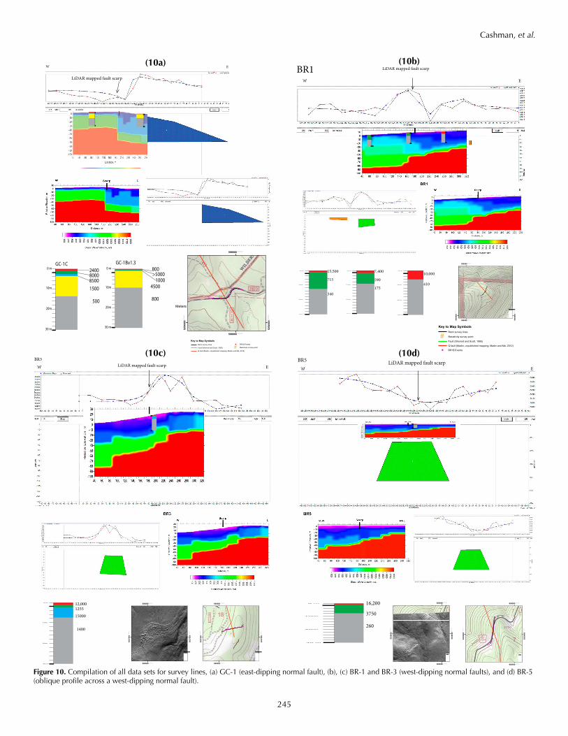
Figure 10. Compilation of all data sets for survey lines, (a) GC-1 (east-dipping normal fault), (b), (c) BR-1 and BR-3 (west-dipping normal faults), and (d) BR-5 (oblique profile across a west-dipping normal fault).
BR1 LiDAR mapped fault scarp
0 m
30 m
10m
20m
0 m
30 m
10m
20m
0 m
30 m
10m
20m
EW
0 m
30 m
10m
20m
0 m
30 m
10m
20m
0 m
30 m
10m
20m
#
599000.000000
Key to Map SymbolsRemi survey lines
# Resistivity survey point
Fault (Sherrod and Scott, 1995)
Q fault (Madin, unpublished mapping; Madin and Ma, 2012)
BR1$ Events
1,000Meters
#
599000.000000
599000.0000005049
000.0
0000
0
5049
000.0
0000
0
1,000Meters
¯
10,000
410
7,400
590
175
15,500
715
340
BR3LiDAR mapped fault scarp
0 m
30 m
10m
20m
EW
600000.000000
600000.000000
5037
000.0
0000
0
5037
000.0
0000
0
Key to Map Symbols
1,000Meters
1:10,000
¯#
##
600000.000000
600000.000000
5037
000.0
0000
0
5037
000.0
0000
0
¯
0 m
30 m
10m
20m
12,0001255
15000
1400
BR5 LiDAR mapped fault scarp
0 m
30 m
10m
20m
EW
0 m
30 m
10m
20m
600000.000000
600000.000000
5 039
000.0
0000
0
5039
000.0
0000
0
Key to Map Symbols
1,000Meters
1:10,000
¯
#
600000.000000
600000.000000
5039
000.0
0000
0
5039
000.0
0000
0
1,000Mete
¯
16,200
3750
260
(10a) (10b)
(10c) (10d)
246
Cashman, et al.
the ridge. If they emerge near the base of the ridge, they are more likely to be mixed with colder water, making detection more difficult. Due to unanticipated access problems, most of the samples for this study were collected near the bottom of the ridge (Fig. 4).
Although it is preferable to sample a flowing spring at the source of a creek, this was not possible in most cases because of limited and difficult access due to private land ownership. Water sampled from Blowdown Ridge was dominantly surface water collected from creeks on the flanks of the ridge. Where observed, the small creeks were fed by diffuse seeps or by small springs along the course of the creek; this is also demonstrated by increasing flow rate downstream. One road cut exposed a several-meter-long seep area (MH15) where water was dripping from an undercut slope. All of these observations are consistent with meteoric water from saturated soil being the primary water source for the creeks on Blowdown Ridge. The only mapped spring sampled, Rock Springs (MH07), is a developed municipal water source. Here, a sample was collected from an apparent well/cistern overflow.
The water samples from Blowdown Ridge are primarily Ca-Mg bicarbonate type waters, and cluster in a relatively nar-row compositional field consistent with meteoric water (Fig. 9). There does not appear to be significant mixing of the meteoric water with water having the characteristics typical of geothermal water (i.e., high chloride and low Ca+Mg). Sample MH07 has a slightly higher ratio of Na+K to Ca+Mg. However, this is the only sample taken from a spring, and it is also from a valley bottom immediately south of Blowdown Ridge, so it samples a broader hydrologic area from the other samples (Fig. 4). Slight chemical differences between this sample and the others are therefore not surprising.
Discussion and Conclusions
Reconnaissance field studies are logistically challenging in the steep and densely forested terrain of the Cascade Range, but are feasible when conducted along logging roads or abandoned logging roads. These provide a level and uniform gravel surface, but buried culverts or inhomogeneous fill material may produce local anomalous readings. A bigger constraint is that surveys are limited to the locations and orientations of the roads, which may not be the best for detecting the geologic features of interest.
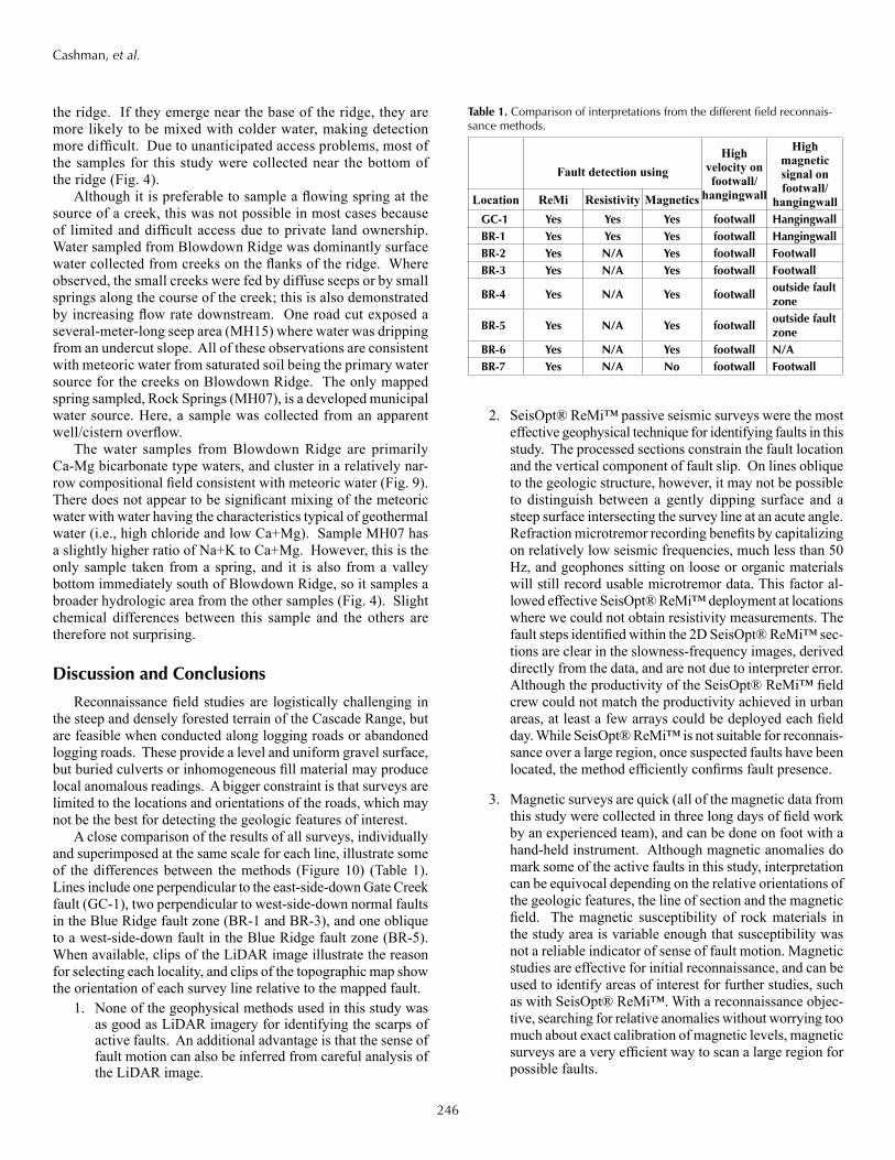
A close comparison of the results of all surveys, individually and superimposed at the same scale for each line, illustrate some of the differences between the methods (Figure 10) (Table 1). Lines include one perpendicular to the east-side-down Gate Creek fault (GC-1), two perpendicular to west-side-down normal faults in the Blue Ridge fault zone (BR-1 and BR-3), and one oblique to a west-side-down fault in the Blue Ridge fault zone (BR-5). When available, clips of the LiDAR image illustrate the reason for selecting each locality, and clips of the topographic map show the orientation of each survey line relative to the mapped fault.
1. None of the geophysical methods used in this study was as good as LiDAR imagery for identifying the scarps of active faults. An additional advantage is that the sense of fault motion can also be inferred from careful analysis of the LiDAR image.
2. SeisOpt® ReMi™ passive seismic surveys were the most effective geophysical technique for identifying faults in this study. The processed sections constrain the fault location and the vertical component of fault slip. On lines oblique to the geologic structure, however, it may not be possible to distinguish between a gently dipping surface and a steep surface intersecting the survey line at an acute angle. Refraction microtremor recording benefits by capitalizing on relatively low seismic frequencies, much less than 50 Hz, and geophones sitting on loose or organic materials will still record usable microtremor data. This factor al-lowed effective SeisOpt® ReMi™ deployment at locations where we could not obtain resistivity measurements. The fault steps identified within the 2D SeisOpt® ReMi™ sec-tions are clear in the slowness-frequency images, derived directly from the data, and are not due to interpreter error. Although the productivity of the SeisOpt® ReMi™ field crew could not match the productivity achieved in urban areas, at least a few arrays could be deployed each field day. While SeisOpt® ReMi™ is not suitable for reconnais-sance over a large region, once suspected faults have been located, the method efficiently confirms fault presence.
3. Magnetic surveys are quick (all of the magnetic data from this study were collected in three long days of field work by an experienced team), and can be done on foot with a hand-held instrument. Although magnetic anomalies do mark some of the active faults in this study, interpretation can be equivocal depending on the relative orientations of the geologic features, the line of section and the magnetic field. The magnetic susceptibility of rock materials in the study area is variable enough that susceptibility was not a reliable indicator of sense of fault motion. Magnetic studies are effective for initial reconnaissance, and can be used to identify areas of interest for further studies, such as with SeisOpt® ReMi™. With a reconnaissance objec-tive, searching for relative anomalies without worrying too much about exact calibration of magnetic levels, magnetic surveys are a very efficient way to scan a large region for possible faults.
Table 1. Comparison of interpretations from the different field reconnais-sance methods.
High velocity on footwall/
hangingwall
High magnetic signal on footwall/
hangingwall
Fault detection using
Location ReMi Resistivity MagneticsGC-1 Yes Yes Yes footwall HangingwallBR-1 Yes Yes Yes footwall HangingwallBR-2 Yes N/A Yes footwall FootwallBR-3 Yes N/A Yes footwall Footwall
BR-4 Yes N/A Yes footwalloutside fault zone
BR-5 Yes N/A Yes footwalloutside fault zone
BR-6 Yes N/A Yes footwall N/ABR-7 Yes N/A No footwall Footwall
247
Cashman, et al.
4. Electrical resistivity surveys were not effective for recon-naissance studies in this environment. The topography, high surface resistivity, and heterogeneity of the geologic materials contributed to the problems with this technique. Several conditions in the field area limited the number of complete circuits (see Results, above) and resulted in too small a database to be useful.
Magnetic surveys at Blowdown Ridge, where no through-going faults were mapped, suggest the locations of several fault offsets. Numerous small faults would be expected in an accommodation zone, and the related fracturing is the reason accommodation zones can be good sites for geothermal upwelling. To follow up on this possibility, refraction microtremor surveys could focus on the potential faults, and water samples from the vicinity of confirmed faults could test for the presence of geothermal water.
Spring geochemistry at Blowdown Ridge did not provide the independent evaluation of geothermal potential that we hoped, because of dilution by meteoric water. This outcome illustrates another ongoing challenge for geothermal exploration in the Cascades. Even though Blowdown Ridge is an isolated topo-graphic high therefore its springs and creeks not diluted by rain and meltwater from Mt. Hood, the water samples from Blowdown Ridge have a strong meteoric signature. Meteoric water from Blowdown Ridge itself feeds the creeks; if geothermal water is present, it does effuse high on the ridge or in enough quantity to overcome the abundant meteoric water.
The ultimate goal of the research -- determining whether any of the methods can locate a geothermal system directly -- is not as straightforward as we hoped. We did not find evidence in the water geochemistry for a good upwelling zone at Blowdown Ridge. In the absence of known upwelling, we cannot compare geophysical survey results for places where it is, and is not, present.
ReferencesBurger, R.H., Sheehan, A.F. and Jones, C.H., 2006, “Introduction to Applied
Geophysics: Exploring the Shallow Subsurface”: W.W. Norton & Co., 600 pp. ISBN-13: 978-0393926378
Crandell, D.R., 1980, Recent eruptive history of Mount Hood, Oregon, and potential hazards from future eruptions: U.S. Geological Survey Bul-letin 1492, 81 p.
Faulds, J.E., Coolbaugh, M., Blewitt, G., and Henry, C.D., 2004, Why is Nevada in hotwater? Structural controls and tectonic model of geothermal systems in the northwestern Great Basin: Geothermal Resources Council Transactions, p. 649-654.
Faulds, J.E., Coolbaugh, M.F., Vice, G.S., and Edwards, M.L., 2006, Charac-terizing structural controls of geothermal fields in the northwestern Great Basin: A progress report: Geothermal Resources Council Transactions, v. 30, p. 69-76.
Faulds, J.E., Coolbaugh, M., Bouchot, V., and Moeck, I., 2009, Structural Controls of Geothermal Reservoirs in Extensional Tectonic Settings: Developing Successful Exploration Strategies, in Huenges, E. and Bruhn, D., eds., Conference Contributions of the I-GET Final Conference, 23-24 February 2009, Potsdam, Germany, p. 51-53.
Faulds, J.E., Hinz, N.H., Coolbaugh, M.F., Cashman, P.H., Kratt, C., Dering, G., Edwards, J., Mayhew, B. and McLachlan, H., 2011, Assessment of favorable structural settings of geothermal systems in the Great Basin, western USA: Geothermal Resources Council Transactions, v. 35, p.
Hammond, W.C., and Thatcher, W., 2005a, Northwest Basin and Range tectonic deformation observed with the Global Positioning System, 1999-2003: Journal of Geophysical Research, v. 110, p. 12.
Louie, J. N., 2001, Faster, better: shear-wave velocity to 100 meters depth from refraction microtremor arrays: Bull. Seismol. Soc. Amer., 91, no. 2 (April), 347-364.
Madin, I. P. and Ma, L., 2012, The Blue Ridge fault, a newly discovered Holocene fault near Mt. Hood, Oregon: SSA meeting, April, 2010
McCaffrey, R., Long, M.D., Goldfinger, C., Zwick, P.C., Nabelek, J.L., Johnson, C.K., and Smith, C., 2000b, Rotation and plate locking at the southern Cascadia subduction zone: Geophysical Research Letters, v. 27, p. 3117-3120.
McCaffrey, R., Qamar, A.I., King, R.W., Wells, R.E., Khazaradze, G., Wil-liams, C.A., Stevens, C.W., Vollick, J.J., and Zwick, P.C., 2007, Fault locking, block rotation and crustal deformation in the Pacific Northwest: GJI Tectonics and Geodynamics, v. 169, p. 27.
Nathenson, M., 2004, Springs on and in the vicinity of Mount Hood volcano, Oregon: USGS Open File Report 2004-1298, 43 p.
Scott, James B., Tiana Rasmussen, Barbara Luke, Wanda Taylor, J. L.,Wagoner, Shane B. Smith, and John N. Louie, 2006, Shallow shear velocity and seismic microzonation of the urban Las Vegas, Nevada ba-sin: Bulletin of the Seismological Society of America, 96, no. 3 (June), 1068-1077, doi: 10.1785/0120050044.
Sherrod, D.R., and Scott, W.E., 1995, Preliminary geologic map of the Mount Hood 30- by 60-minute quadrangle, Cascade Range, north-central Or-egon: U.S. Geological Survey Open-File Report 95-219, scale 1:100,000.
Shields, G., K. Allander, R. Brigham, R. Crosbie, L. Trimble, M. Sleeman, R. Tucker, H. Zhan, and J. N. Louie, 1998, Geophysical surveys of an active fault: results from Pahrump Valley, California-Nevada border: Bulletin of the Seismological Society of America, 88, 270-275.
Wells, R.E., Weaver, C.S. and Blakely, R.J., 1998, Fore-arc migration in Cas-cadia and its neotectonic significance: Geology, v. 26, no. 8, p. 759-762.
Wise, W.S., 1968, Geology of the Mount Hood volcano, inDole, H.M., ed., Andesite Conference Guidebook: Oregon Department of Geology and Mineral Industries Bulletin 62, p. 81-98.

248