Embed Size (px)
Citation preview
39th IABSE Symposium – Engineering the Future September 21-23 2017, Vancouver, Canada
1
Testing Bridges to Failure - Experiences
Jens Häggström, Niklas Bagge, Jonny Nilimaa, Gabriel Sas, Thomas Blanksvärd, Björn Täljsten, Lennart Elfgren
Luleå University of Technology, Luleå, Sweden
Arto Puurula
Savonia University of Applied Sciences, Kuopio, Finland
Lahja Rydberg-Forssbeck, Anders Carolin
Trafikverket, Stockholm & Luleå, Sweden
Contact: [email protected]
Abstract
Four bridges of different types have been tested to failure and the results have been compared to the load-carrying capacity calculated using standard code models and advanced numerical methods. The results may help to make accurate assessments of similar existing bridges. Here it is necessary to know the real behaviour, weak points, and to be able to model the load-carrying capacity in a correct way. The four bridges were: (1) a one span steel truss railway bridge; (2) a two span strengthened concrete trough railway bridge; (3) a one span concrete trough bridge tested in fatigue; and (4) a five span prestressed concrete road bridge. The unique results in the paper are the experiences of the real failure types, the robustness/weakness of the bridges, and the accuracy of different codes and models.
Keywords: bridges, testing, assessment, load-carrying capacity, reinforced concrete, prestressed concrete, steel, analysis, codes.
1 Introduction
Assessment of the load-carrying capacity of existing bridges is an important task. Four bridges in Sweden have been tested to failure and assessed using standard code models and advanced numerical methods.
The results may help to make more accurate assessments of similar existing bridges. Here it is necessary to know the real behaviour, weak points, and to be able to model the load-carrying capacity in a correct way.
39th IABSE Symposium – Engineering the Future September 21-23 2017, Vancouver, Canada
2
2 The Åby Steel Truss Railway Bridge
2.1 Background
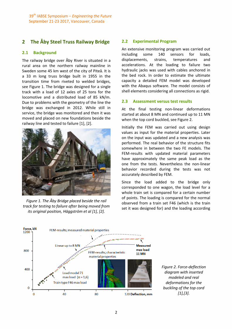
The railway bridge over Åby River is situated in a rural area on the northern railway mainline in Sweden some 45 km west of the city of Piteå. It is a 33 m long truss bridge built in 1955 in the transition time from riveted to welded bridges, see Figure 1. The bridge was designed for a single track with a load of 12 axles of 25 tons for the locomotive and a distributed load of 85 kN/m. Due to problems with the geometry of the line the bridge was exchanged in 2012. While still in service, the bridge was monitored and then it was moved and placed on new foundations beside the railway line and tested to failure [1], [2].
Figure 1. The Åby Bridge placed beside the rail track for testing to failure after being moved from
its original position, Häggström et al [1], [2].
2.2 Experimental Program
An extensive monitoring program was carried out including some 140 sensors for loads, displacements, strains, temperatures and accelerations. At the loading to failure two hydraulic jacks was used with cables anchored in the bed rock. In order to estimate the ultimate capacity a detailed FEM model was developed with the Abaqus software. The model consists of shell elements considering all connections as rigid.
2.3 Assessment versus test results
At the final testing non-linear deformations started at about 8 MN and continued up to 11 MN when the top cord buckled, see Figure 2.
Initially the FEM was carried out using design values as input for the material properties. Later on the input was updated and a new analysis was performed. The real behavior of the structure fits somewhere in between the two FE models. The FEM-results with updated material parameters have approximately the same peak load as the one from the tests. Nevertheless the non-linear behavior recorded during the tests was not accurately described by FEM.
Since the load added to the bridge only corresponded to one wagon, the load level for a whole train set is compared for a certain number of points. The loading is compared for the normal observed from a train set F46 (which is the train set it was designed for) and the loading according
Figure 2. Force-deflection diagram with inserted
modeled and real deformations for the
buckling of the top cord [1],[3].
39th IABSE Symposium – Engineering the Future September 21-23 2017, Vancouver, Canada
3
to current standards (Eurocode) for new bridges along the line subjected to the heaviest axle loads
in Sweden (Load model 71 with =1,6). Safety or dynamic amplification factors are disregarded. The comparison shows that the bridge could withstand
loading that substantially exceeds both the load it was designed for as well as the load the model in use today before failing.
The influence of damages to the bridge has been studied in the EU-project MAINLINE [3], [4].
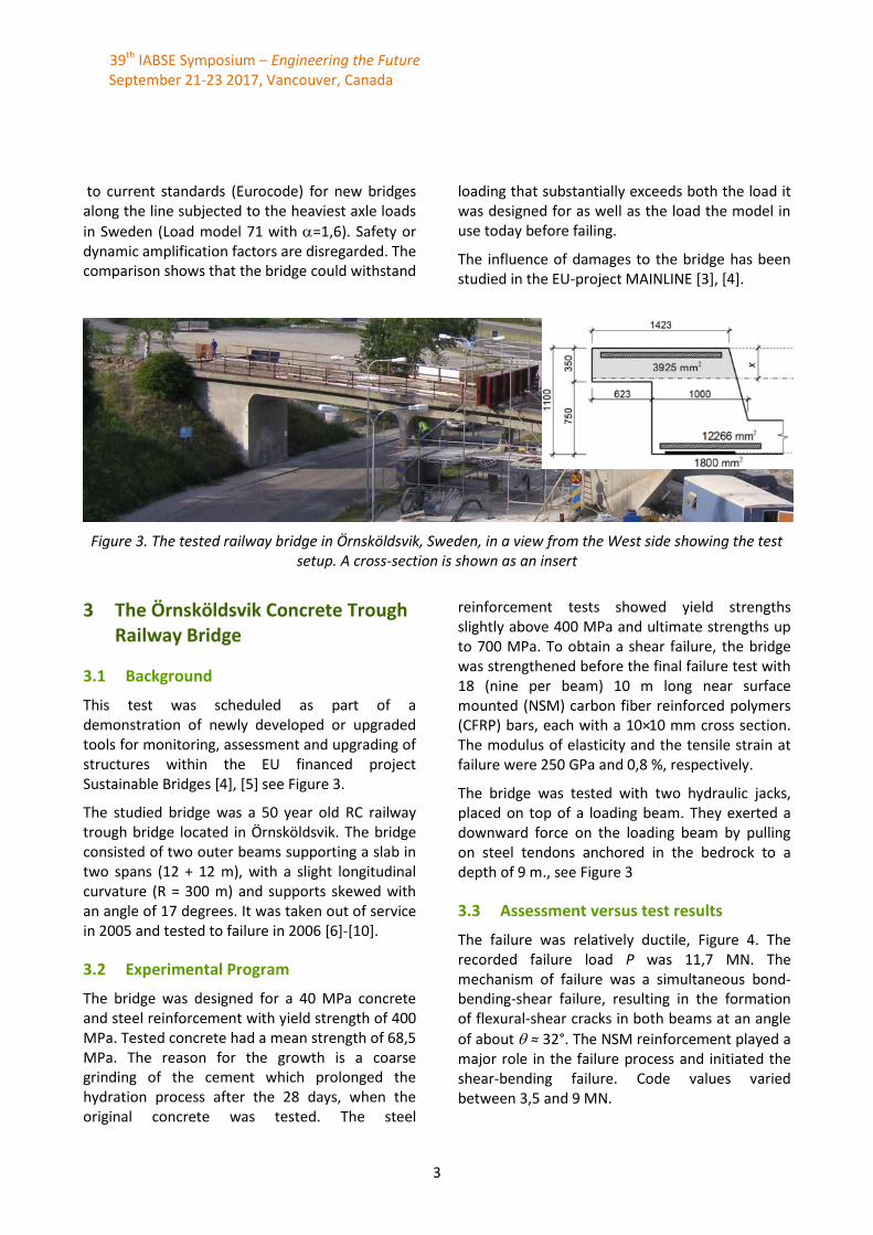
Figure 3. The tested railway bridge in Örnsköldsvik, Sweden, in a view from the West side showing the test setup. A cross-section is shown as an insert
3 The Örnsköldsvik Concrete Trough Railway Bridge
3.1 Background
This test was scheduled as part of a demonstration of newly developed or upgraded tools for monitoring, assessment and upgrading of structures within the EU financed project Sustainable Bridges [4], [5] see Figure 3.
The studied bridge was a 50 year old RC railway trough bridge located in Örnsköldsvik. The bridge consisted of two outer beams supporting a slab in two spans (12 + 12 m), with a slight longitudinal curvature (R = 300 m) and supports skewed with an angle of 17 degrees. It was taken out of service in 2005 and tested to failure in 2006 [6]-[10].
3.2 Experimental Program
The bridge was designed for a 40 MPa concrete and steel reinforcement with yield strength of 400 MPa. Tested concrete had a mean strength of 68,5 MPa. The reason for the growth is a coarse grinding of the cement which prolonged the hydration process after the 28 days, when the original concrete was tested. The steel
reinforcement tests showed yield strengths slightly above 400 MPa and ultimate strengths up to 700 MPa. To obtain a shear failure, the bridge was strengthened before the final failure test with 18 (nine per beam) 10 m long near surface mounted (NSM) carbon fiber reinforced polymers (CFRP) bars, each with a 10×10 mm cross section. The modulus of elasticity and the tensile strain at failure were 250 GPa and 0,8 %, respectively.
The bridge was tested with two hydraulic jacks, placed on top of a loading beam. They exerted a downward force on the loading beam by pulling on steel tendons anchored in the bedrock to a depth of 9 m., see Figure 3
3.3 Assessment versus test results
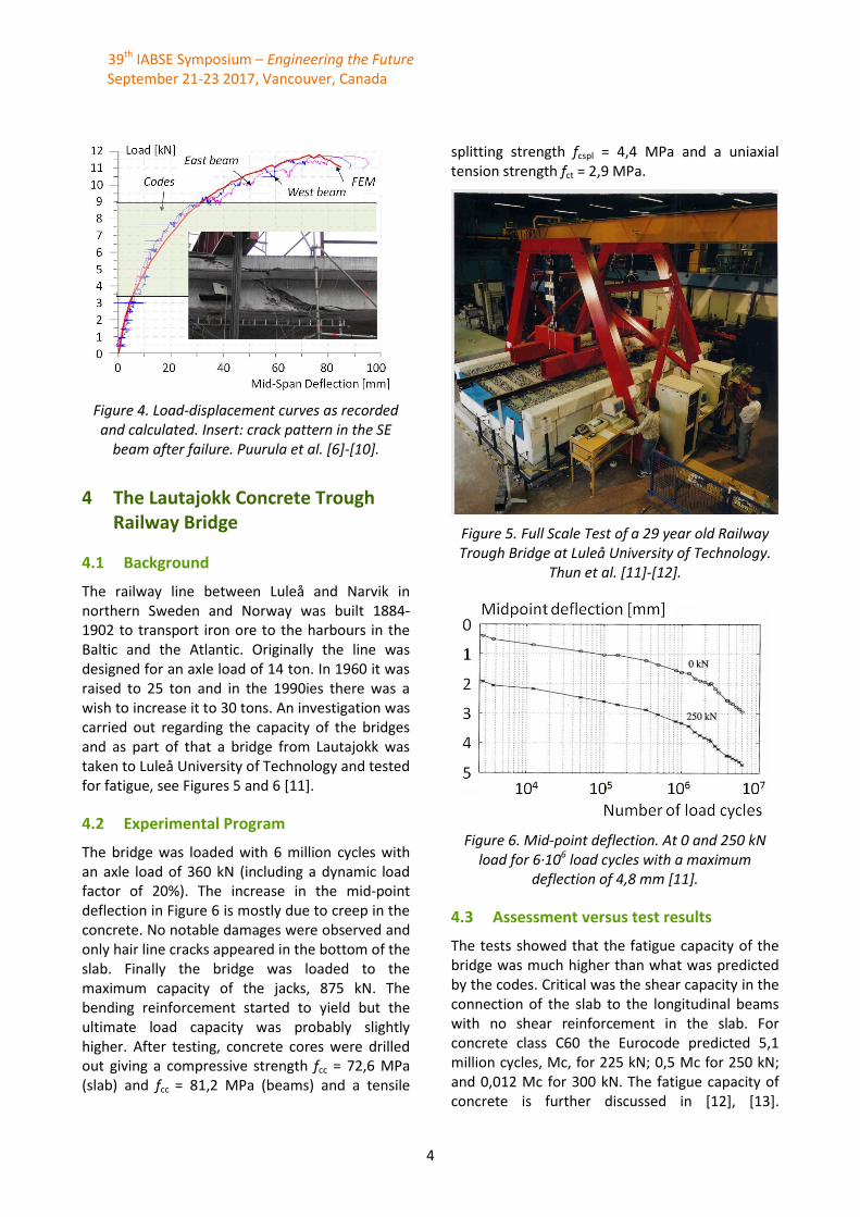
The failure was relatively ductile, Figure 4. The recorded failure load P was 11,7 MN. The mechanism of failure was a simultaneous bond-bending-shear failure, resulting in the formation of flexural-shear cracks in both beams at an angle
of about ≈ 32°. The NSM reinforcement played a major role in the failure process and initiated the shear-bending failure. Code values varied between 3,5 and 9 MN.
39th IABSE Symposium – Engineering the Future September 21-23 2017, Vancouver, Canada
4
Figure 4. Load-displacement curves as recorded and calculated. Insert: crack pattern in the SE
beam after failure. Puurula et al. [6]-[10].
4 The Lautajokk Concrete Trough Railway Bridge
4.1 Background
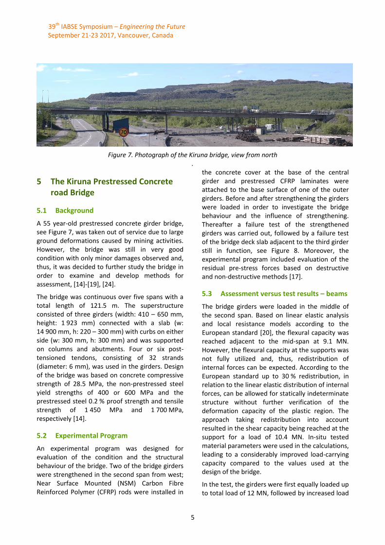
The railway line between Luleå and Narvik in northern Sweden and Norway was built 1884-1902 to transport iron ore to the harbours in the Baltic and the Atlantic. Originally the line was designed for an axle load of 14 ton. In 1960 it was raised to 25 ton and in the 1990ies there was a wish to increase it to 30 tons. An investigation was carried out regarding the capacity of the bridges and as part of that a bridge from Lautajokk was taken to Luleå University of Technology and tested for fatigue, see Figures 5 and 6 [11].
4.2 Experimental Program
The bridge was loaded with 6 million cycles with an axle load of 360 kN (including a dynamic load factor of 20%). The increase in the mid-point deflection in Figure 6 is mostly due to creep in the concrete. No notable damages were observed and only hair line cracks appeared in the bottom of the slab. Finally the bridge was loaded to the maximum capacity of the jacks, 875 kN. The bending reinforcement started to yield but the ultimate load capacity was probably slightly higher. After testing, concrete cores were drilled out giving a compressive strength fcc = 72,6 MPa (slab) and fcc = 81,2 MPa (beams) and a tensile
splitting strength fcspl = 4,4 MPa and a uniaxial tension strength fct = 2,9 MPa.
Figure 5. Full Scale Test of a 29 year old Railway Trough Bridge at Luleå University of Technology.
Thun et al. [11]-[12].
Figure 6. Mid-point deflection. At 0 and 250 kN load for 6·106 load cycles with a maximum
deflection of 4,8 mm [11].
4.3 Assessment versus test results
The tests showed that the fatigue capacity of the bridge was much higher than what was predicted by the codes. Critical was the shear capacity in the connection of the slab to the longitudinal beams with no shear reinforcement in the slab. For concrete class C60 the Eurocode predicted 5,1 million cycles, Mc, for 225 kN; 0,5 Mc for 250 kN; and 0,012 Mc for 300 kN. The fatigue capacity of concrete is further discussed in [12], [13].
39th IABSE Symposium – Engineering the Future September 21-23 2017, Vancouver, Canada
5
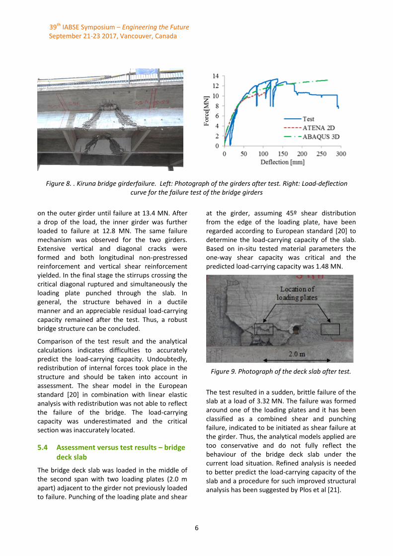
Figure 7. Photograph of the Kiruna bridge, view from north .
5 The Kiruna Prestressed Concrete road Bridge
5.1 Background
A 55 year-old prestressed concrete girder bridge, see Figure 7, was taken out of service due to large ground deformations caused by mining activities. However, the bridge was still in very good condition with only minor damages observed and, thus, it was decided to further study the bridge in order to examine and develop methods for assessment, [14]-[19], [24].
The bridge was continuous over five spans with a total length of 121.5 m. The superstructure consisted of three girders (width: 410 – 650 mm, height: 1 923 mm) connected with a slab (w: 14 900 mm, h: 220 – 300 mm) with curbs on either side (w: 300 mm, h: 300 mm) and was supported on columns and abutments. Four or six post-tensioned tendons, consisting of 32 strands (diameter: 6 mm), was used in the girders. Design of the bridge was based on concrete compressive strength of 28.5 MPa, the non-prestressed steel yield strengths of 400 or 600 MPa and the prestressed steel 0.2 % proof strength and tensile strength of 1 450 MPa and 1 700 MPa, respectively [14].
5.2 Experimental Program
An experimental program was designed for evaluation of the condition and the structural behaviour of the bridge. Two of the bridge girders were strengthened in the second span from west; Near Surface Mounted (NSM) Carbon Fibre Reinforced Polymer (CFRP) rods were installed in
the concrete cover at the base of the central girder and prestressed CFRP laminates were attached to the base surface of one of the outer girders. Before and after strengthening the girders were loaded in order to investigate the bridge behaviour and the influence of strengthening. Thereafter a failure test of the strengthened girders was carried out, followed by a failure test of the bridge deck slab adjacent to the third girder still in function, see Figure 8. Moreover, the experimental program included evaluation of the residual pre-stress forces based on destructive and non-destructive methods [17].
5.3 Assessment versus test results – beams
The bridge girders were loaded in the middle of the second span. Based on linear elastic analysis and local resistance models according to the European standard [20], the flexural capacity was reached adjacent to the mid-span at 9.1 MN. However, the flexural capacity at the supports was not fully utilized and, thus, redistribution of internal forces can be expected. According to the European standard up to 30 % redistribution, in relation to the linear elastic distribution of internal forces, can be allowed for statically indeterminate structure without further verification of the deformation capacity of the plastic region. The approach taking redistribution into account resulted in the shear capacity being reached at the support for a load of 10.4 MN. In-situ tested material parameters were used in the calculations, leading to a considerably improved load-carrying capacity compared to the values used at the design of the bridge.
In the test, the girders were first equally loaded up to total load of 12 MN, followed by increased load
39th IABSE Symposium – Engineering the Future September 21-23 2017, Vancouver, Canada
6
Figure 8. . Kiruna bridge girderfailure. Left: Photograph of the girders after test. Right: Load-deflection curve for the failure test of the bridge girders
on the outer girder until failure at 13.4 MN. After a drop of the load, the inner girder was further loaded to failure at 12.8 MN. The same failure mechanism was observed for the two girders. Extensive vertical and diagonal cracks were formed and both longitudinal non-prestressed reinforcement and vertical shear reinforcement yielded. In the final stage the stirrups crossing the critical diagonal ruptured and simultaneously the loading plate punched through the slab. In general, the structure behaved in a ductile manner and an appreciable residual load-carrying capacity remained after the test. Thus, a robust bridge structure can be concluded.
Comparison of the test result and the analytical calculations indicates difficulties to accurately predict the load-carrying capacity. Undoubtedly, redistribution of internal forces took place in the structure and should be taken into account in assessment. The shear model in the European standard [20] in combination with linear elastic analysis with redistribution was not able to reflect the failure of the bridge. The load-carrying capacity was underestimated and the critical section was inaccurately located.
5.4 Assessment versus test results – bridge deck slab
The bridge deck slab was loaded in the middle of the second span with two loading plates (2.0 m apart) adjacent to the girder not previously loaded to failure. Punching of the loading plate and shear
at the girder, assuming 45º shear distribution from the edge of the loading plate, have been regarded according to European standard [20] to determine the load-carrying capacity of the slab. Based on in-situ tested material parameters the one-way shear capacity was critical and the predicted load-carrying capacity was 1.48 MN.
Figure 9. Photograph of the deck slab after test.
The test resulted in a sudden, brittle failure of the slab at a load of 3.32 MN. The failure was formed around one of the loading plates and it has been classified as a combined shear and punching failure, indicated to be initiated as shear failure at the girder. Thus, the analytical models applied are too conservative and do not fully reflect the behaviour of the bridge deck slab under the current load situation. Refined analysis is needed to better predict the load-carrying capacity of the slab and a procedure for such improved structural analysis has been suggested by Plos et al [21].
39th IABSE Symposium – Engineering the Future September 21-23 2017, Vancouver, Canada
7
6 Conclusions
The results of the tests to failure of four different bridges were presented. The tests were carried out on decommissioned structures deemed for demolition. Numerical tools are proven to be reliable instruments for assessment especially when combined with material testing. All the tested structures had a considerable “hidden” capacity which is little reflected during ordinary assessment processes and which is accounted for neither in standards nor in design guidelines [22]. Perhaps some of these differences arise from redistribution of loads during the testing in the statically indeterminate structures. Another reason is the high safety factors that are used both for loads and materials. Methods to strengthen structures with insufficient capacity are given and discussed in e.g. [3], [5] and [23].
7 Acknowledgements
The authors gratefully acknowledge financial support from the European Union, Trafikverket, Network Rail, LKAB/HLRC, SBUF and LTU. They also thank colleagues and collaborators who have worked in the projects Sustainable Bridges and Mainline, and the Swedish Universities of the Built Environment (Oskar Larsson and Sven Thelandersson, LTH; Kent Gylltoft, Karin Lundgren and Mario Plos, Chalmers; and Raid Karoumi, Mikael Hallgren and Håkan Sundquist, KTH).
The experimental work and monitoring campaigns in Sweden were carried out in cooperation with staff of Complab at LTU.
8 References
[1] Häggström, J. (2016). Evaluation of the Load Carrying Capacity of a Steel Truss Railway Bridge: Testing, Theory and Evaluation. Licentiate Thesis, Luleå University of Technology, 2016, 142 pp. ISBN: 978-91-7583-740-6, see http://ltu.diva-portal.org/
[2] Häggström, J., Blanksvärd, T., Täljsten, B. (2017). Bridge over Åby River: Evaluation
of full scale testing. Report, Luleå University of Technology, 2017, 131 pp., see http://ltu.diva-portal.org/
[3] MAINLINE (2014). MAINtenance, renewal and Improvement of rail transport Infra-structure to reduce Economic and environmental impacts. A European FP7 Research Project during 2011-2014. Some 20 reports are available, see e.g. D1.2 at http://www.mainline-project.eu/
[4] Paulsson, B., Bell, B., Schewe, B., Jensen, J. S., Carolin, A., and Elfgren, L. (2016). Results and Experiences from European Research Projects on Railway Bridges. 19th IABSE Congress Stockholm 21-23 September 2016, Zürich, 2016, pp. 2570 – 2578. ISBN 978-3-85748-144-4.
[5] Sustainable Bridges (2007). Assessment for Future Traffic Demands and Longer Lives. A European FP 6 Integrated Research Project during 2003-2007. Four guidelines and 35 background documents are available at www.sustainablebridges.net
[6] Elfgren L., Enochsson O., Puurula A., Thun H. (2008). Field Test of a Concrete Bridge in Örnsköldsvik. Sustainable Bridges, Report SB-7.3, 2008, 406 pp. www.sustainablebridges.net
[7] Puurula, A. (2012), Load-carrying Capacity of a Strengthened Reinforced Concrete Bridge: Non-linear Finite Element Modeling of a Test to Failure. Assessment of Train Load Capacity of a Two Span Railway Trough Bridge in Örnsköldsvik Strengthened with Bars of Carbon Fibre Reinforced Polymers (CFRP). Doctoral Thesis, Luleå University of Technology, 2012, 332 p.
[8] Puurula, A., Enochsson, O., Sas, G., Blanksvärd, T., Ohlsson, U., Bernspång, L., Elfgren, L. (2014). Loading to failure and 3D nonlinear FE modelling of a strengthened RC bridge. Str.. & Infrastruct. Engin., 10(12), 1606-1619.
[9] Puurula, A., Enochsson, O., Sas, G., Blanksvärd, T., Ohlsson, U., Bernspång, L., Täljsten, B., Carolin, A., Paulsson, B., Elfgren, L. (2015). Assessment of the Strengthening of an RC Railway Bridge with CFRP Utilizing a Full-Scale Failure Test and Finite-Element
39th IABSE Symposium – Engineering the Future September 21-23 2017, Vancouver, Canada
8
Analysis, J. Struct. Engineering, ASCE, 2015, 141, D4014008, 11 p.
[10] Puurula, A., Enochsson, O., Sas, G., Blank-svärd, Th., Ohlsson, U., Bernspång, L., Täljsten, B., Elfgren, L. (2016). 3D non-linear FE analysis of a full scale test to failure of a RC Railway Bridge strengthened with carbon fibre bars. 19th IABSE Congress Stockholm 21-23 September 2016, Zürich, 2016, pp. 2527 – 2535. ISBN 978-3-85748-144-4.
[11] Thun, H., Ohlsson, U., Elfgren, L. (2000). Fatigue Capacity of Small Railway Concrete Bridges: Prevision of the Results of Swedish Full-scale Tests. Comparison and Analyses. Final Report to the European Rail Research Institute, ERRI D216, Structural Engineering, Luleå University of Technology, 99pp. http://ltu.diva-portal.org/
[12] Thun, H., Ohlsson, U., Elfgren, L. (2011): A deformation criterion for fatigue of concrete in tension. Structural Concrete, Journal of fib, Vol 12, Issue 3, pp 187-197.
[13] Elfgren, L. (2015): Fatigue Capacity of Concrete Structures: Assessment of Railway Bridges. Research Report, Luleå University of Technology, 103 pp. Available at http://ltu.diva-portal.org/
[14] Bagge, N., Nilimaa, J., Blanksvärd, T., Elfgren, L. (2014). Instrumentation and full-scale test of a post-tensioned concrete bridge. Nordic Concrete Research, 51, 63-83.
[15] Bagge, N., Shu, J., Plos, M., Elfgren, L. (2015). Punching Capacity of a Reinforced Concrete Bridge Deck Slab Loaded to Failure. Paper presented at the Nordic Concrete Federation: Residual capacity of deteriorated concrete structures, Oslo, Norway, http://ltu.diva-portal.org/
[16] Bagge, N., Nilimaa, J., Blanksvärd, T., Täljsten, B., Elfgren, L., Sundquist, H., Carolin, A. (2016). Assessment and failure test of a prestressed concrete bridge. In "Life-Cycle of Engineering Systems: Empahasis on Sustainable Civil Infrastructure", Ed. by Bakker, Frangopol &
van Breugel, London, Taylor & Francis Group, ISBN 978-1-138-02847-0, paper C134, Abstract p 194, Full paper on USB card pp 1958-1063.
[17] Bagge, N., Nilimaa, J., Elfgren, L. (2017). In situ methods to determine residual prestress forces in concrete bridges. Engineering Structures, Vol. 135, 41-52p.
[18] Huang, Z., Grip, N., Sabourova, N., Bagge, N., Tu, Y., Elfgren, L. (2016). Modelling of damage and its use in assessment of a prestressed bridge. In Proceedings of the 19th Congress of IABSE in Stockholm, pp 2093-2108. A version was also published 2016-04-30 as a Research Report, Luleå Univ. of Technology, 22 pp,. http://ltu.diva-portal.org/
[19] Nilimaa, Jonny. (2015). Concrete bridges: Improved load capacity. (Ph.D. Thesis), Luleå University of Technology, Luleå, Sweden, 176 pp.
[20] CEN. (2005). Eurocode 2: Design of concrete structures - Concrete bridges - Design and detailing rules SS-EN 1992-2:2005 (pp. 104). Brussels: Eur. Com. for Standard. (CEN).
[21] Plos, M., Shu, J., Zandi, K. Z., & Lundgren, K. (2017). A multi-level structural assessment strategy for reinforced concrete bridge deck slabs. Structure and Infrastructure Engineering, 13(2), 223-241
[22] Nilimaa, J., Bagge, N., Häggström, J., Blanksvärd, Th., Sas, Gabriel., Täljsten, B., Elfgren, L. (2016). More realistic Codes for Exisiting Bridges. 19th IABSE Congress, Stockholm 21-23 September 2016. Zürich, pp 399-407, ISBN 978-3-85748-144-4.
[23] Täljsten B., Blanksvärd T., Sas G. (2016). Kompositförstärkning av betong (Strength-ening of Concrete Structures with Composites. In Swedish) Svensk Byggtjänst, Stockholm 2016. ISBN:978-91-7333-763-2, pp. 177.
[24] Bagge, Niklas (2017). Structural Assessment Procedures for Existing Concrete Bridges. Experiences from failure tests of the Kiruna Bridge. Doctoral thesis, LTU. 310 pp.