Embed Size (px)
Citation preview
Testing and Evaluation to Improve Data Security ofAutomotive Embedded SystemsMaster’s thesis in Computer Systems & Networks
JOHANNES WESCHKEFILIP HESSLUND
Department of Computer Science and EngineeringCHALMERS UNIVERSITY OF TECHNOLOGYGoteborg, Sweden 2015Master’s thesis 2011:01
Testing and Evaluation to Improve Data Security of Automotive Embedded SystemsJOHANNES WESCHKEFILIP HESSLUND
c© JOHANNES WESCHKE , FILIP HESSLUND , 2015
Master’s thesis 2011:01ISSN 1652-8557Department of Computer Science and EngineeringChalmers University of TechnologySE-412 96 GoteborgSwedenTelephone: +46 (0)31-772 1000
Chalmers ReproserviceGoteborg, Sweden 2015
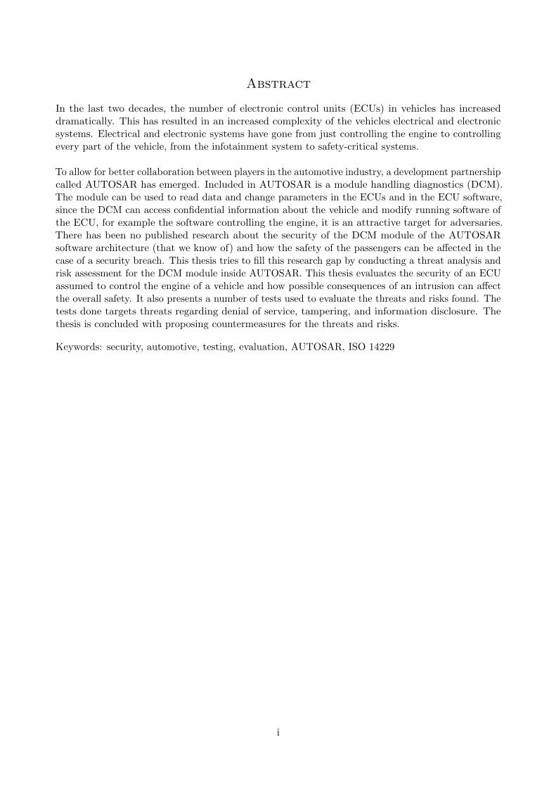
Abstract
In the last two decades, the number of electronic control units (ECUs) in vehicles has increaseddramatically. This has resulted in an increased complexity of the vehicles electrical and electronicsystems. Electrical and electronic systems have gone from just controlling the engine to controllingevery part of the vehicle, from the infotainment system to safety-critical systems.
To allow for better collaboration between players in the automotive industry, a development partnershipcalled AUTOSAR has emerged. Included in AUTOSAR is a module handling diagnostics (DCM).The module can be used to read data and change parameters in the ECUs and in the ECU software,since the DCM can access confidential information about the vehicle and modify running software ofthe ECU, for example the software controlling the engine, it is an attractive target for adversaries.There has been no published research about the security of the DCM module of the AUTOSARsoftware architecture (that we know of) and how the safety of the passengers can be affected in thecase of a security breach. This thesis tries to fill this research gap by conducting a threat analysis andrisk assessment for the DCM module inside AUTOSAR. This thesis evaluates the security of an ECUassumed to control the engine of a vehicle and how possible consequences of an intrusion can affectthe overall safety. It also presents a number of tests used to evaluate the threats and risks found. Thetests done targets threats regarding denial of service, tampering, and information disclosure. Thethesis is concluded with proposing countermeasures for the threats and risks.
Keywords: security, automotive, testing, evaluation, AUTOSAR, ISO 14229
i

Acknowledgements
We would like to thank Tomas Olovsson, at Chalmers Univerity of Technology, and Christian Sandbergand Mafijul Islam, from Volvo AB, for supervising this thesis, and for their invaluable help and inputduring this work. We would also like to thank Erland Jonsson, at Chalmers University of Technology,for being our examiner.
ii
Contents
Abstract i
Acknowledgements ii
Contents iii
1 Introduction 11.1 Related Work . . . . . . . . . . . . . . . . . . . . . . . . . . . . . . . . . . . . . . . . . . . 21.2 Research Methodology . . . . . . . . . . . . . . . . . . . . . . . . . . . . . . . . . . . . . . 31.3 Thesis outline . . . . . . . . . . . . . . . . . . . . . . . . . . . . . . . . . . . . . . . . . . . 4
2 Terms and Definitions 5
3 Security model 63.1 The HEAVENS Security Model . . . . . . . . . . . . . . . . . . . . . . . . . . . . . . . . . 63.1.1 STRIDE . . . . . . . . . . . . . . . . . . . . . . . . . . . . . . . . . . . . . . . . . . . . 63.2 Penetration testing . . . . . . . . . . . . . . . . . . . . . . . . . . . . . . . . . . . . . . . . 103.3 Fuzzing . . . . . . . . . . . . . . . . . . . . . . . . . . . . . . . . . . . . . . . . . . . . . . 11
4 AUTOSAR 124.1 Automotive Open System Architecture 4.1 . . . . . . . . . . . . . . . . . . . . . . . . . . 124.2 ISO standards for vehicle diagnostic . . . . . . . . . . . . . . . . . . . . . . . . . . . . . . 15
5 Threat modeling 175.1 Diagnostic communication . . . . . . . . . . . . . . . . . . . . . . . . . . . . . . . . . . . . 185.2 ECU . . . . . . . . . . . . . . . . . . . . . . . . . . . . . . . . . . . . . . . . . . . . . . . . 185.3 Tester . . . . . . . . . . . . . . . . . . . . . . . . . . . . . . . . . . . . . . . . . . . . . . . 195.4 Security requirements . . . . . . . . . . . . . . . . . . . . . . . . . . . . . . . . . . . . . . 19
6 Security Tests 216.1 Experimental Environment . . . . . . . . . . . . . . . . . . . . . . . . . . . . . . . . . . . 216.2 Attack Trees . . . . . . . . . . . . . . . . . . . . . . . . . . . . . . . . . . . . . . . . . . . 236.2.1 Information Disclosure / System Reconnaissance . . . . . . . . . . . . . . . . . . . . . . 236.2.2 Tampering of ECU Software . . . . . . . . . . . . . . . . . . . . . . . . . . . . . . . . . 236.2.3 Denial of Service . . . . . . . . . . . . . . . . . . . . . . . . . . . . . . . . . . . . . . . . 236.3 Information Disclosure / System Reconnaissance Test . . . . . . . . . . . . . . . . . . . . 236.3.1 System Scan . . . . . . . . . . . . . . . . . . . . . . . . . . . . . . . . . . . . . . . . . . 236.3.2 System Probing . . . . . . . . . . . . . . . . . . . . . . . . . . . . . . . . . . . . . . . . 276.3.3 Packet sniffing . . . . . . . . . . . . . . . . . . . . . . . . . . . . . . . . . . . . . . . . . 276.3.4 Restricted Memory Address scan . . . . . . . . . . . . . . . . . . . . . . . . . . . . . . . 276.3.5 Message handling rate . . . . . . . . . . . . . . . . . . . . . . . . . . . . . . . . . . . . . 276.4 Tampering of ECU Software Test . . . . . . . . . . . . . . . . . . . . . . . . . . . . . . . . 286.4.1 Man In The Middle . . . . . . . . . . . . . . . . . . . . . . . . . . . . . . . . . . . . . . 286.4.2 Brute force security access key . . . . . . . . . . . . . . . . . . . . . . . . . . . . . . . . 286.4.3 Seed/Key Sniffing . . . . . . . . . . . . . . . . . . . . . . . . . . . . . . . . . . . . . . . 286.4.4 Seed Entropy . . . . . . . . . . . . . . . . . . . . . . . . . . . . . . . . . . . . . . . . . . 286.4.5 Restricted Memory Address Write . . . . . . . . . . . . . . . . . . . . . . . . . . . . . . 296.5 Denial of Service Test . . . . . . . . . . . . . . . . . . . . . . . . . . . . . . . . . . . . . . 29
iii
6.5.1 Fuzzing based Security Tests . . . . . . . . . . . . . . . . . . . . . . . . . . . . . . . . . 296.5.2 Random Fuzzing . . . . . . . . . . . . . . . . . . . . . . . . . . . . . . . . . . . . . . . . 296.5.3 Intelligent Fuzzing . . . . . . . . . . . . . . . . . . . . . . . . . . . . . . . . . . . . . . . 306.5.4 Flooding . . . . . . . . . . . . . . . . . . . . . . . . . . . . . . . . . . . . . . . . . . . . 30
7 Results and test evaluations 337.1 Information Disclosure / System Reconnaissance . . . . . . . . . . . . . . . . . . . . . . . 337.1.1 System Scan . . . . . . . . . . . . . . . . . . . . . . . . . . . . . . . . . . . . . . . . . . 337.1.2 System Probing . . . . . . . . . . . . . . . . . . . . . . . . . . . . . . . . . . . . . . . . 337.1.3 Packet sniffing . . . . . . . . . . . . . . . . . . . . . . . . . . . . . . . . . . . . . . . . . 337.1.4 Restricted Memory Address scan . . . . . . . . . . . . . . . . . . . . . . . . . . . . . . . 337.1.5 Message handling rate . . . . . . . . . . . . . . . . . . . . . . . . . . . . . . . . . . . . . 347.2 Tampering of ECU Software . . . . . . . . . . . . . . . . . . . . . . . . . . . . . . . . . . . 347.2.1 Man In The Middle . . . . . . . . . . . . . . . . . . . . . . . . . . . . . . . . . . . . . . 347.2.2 Brute force security access key . . . . . . . . . . . . . . . . . . . . . . . . . . . . . . . . 347.2.3 Seed/Key sniffing . . . . . . . . . . . . . . . . . . . . . . . . . . . . . . . . . . . . . . . 347.2.4 Seed Entropy . . . . . . . . . . . . . . . . . . . . . . . . . . . . . . . . . . . . . . . . . . 347.2.5 Restricted Memory Address Write . . . . . . . . . . . . . . . . . . . . . . . . . . . . . . 357.3 Denial of Service . . . . . . . . . . . . . . . . . . . . . . . . . . . . . . . . . . . . . . . . . 357.3.1 Random Fuzzing . . . . . . . . . . . . . . . . . . . . . . . . . . . . . . . . . . . . . . . . 357.3.2 Intelligent Fuzzing . . . . . . . . . . . . . . . . . . . . . . . . . . . . . . . . . . . . . . . 357.3.3 Flooding . . . . . . . . . . . . . . . . . . . . . . . . . . . . . . . . . . . . . . . . . . . . 35
8 Discussion and countermeasures 378.1 Information Disclosure / System Reconnaissance . . . . . . . . . . . . . . . . . . . . . . . 378.1.1 System Scan . . . . . . . . . . . . . . . . . . . . . . . . . . . . . . . . . . . . . . . . . . 378.1.2 System Probing . . . . . . . . . . . . . . . . . . . . . . . . . . . . . . . . . . . . . . . . 378.1.3 Packet sniffing . . . . . . . . . . . . . . . . . . . . . . . . . . . . . . . . . . . . . . . . . 388.1.4 Restricted Memory Address scan . . . . . . . . . . . . . . . . . . . . . . . . . . . . . . . 388.1.5 Message handling rate . . . . . . . . . . . . . . . . . . . . . . . . . . . . . . . . . . . . . 388.2 Tampering of ECU Software . . . . . . . . . . . . . . . . . . . . . . . . . . . . . . . . . . . 388.2.1 Man In The Middle . . . . . . . . . . . . . . . . . . . . . . . . . . . . . . . . . . . . . . 388.2.2 Brute force security access key test . . . . . . . . . . . . . . . . . . . . . . . . . . . . . . 398.2.3 Seed/Key sniffing . . . . . . . . . . . . . . . . . . . . . . . . . . . . . . . . . . . . . . . 408.2.4 Seed Entropy . . . . . . . . . . . . . . . . . . . . . . . . . . . . . . . . . . . . . . . . . . 408.2.5 Restricted Memory Address Write . . . . . . . . . . . . . . . . . . . . . . . . . . . . . . 408.3 Denial of Service . . . . . . . . . . . . . . . . . . . . . . . . . . . . . . . . . . . . . . . . . 408.3.1 Fuzzing based Security Tests . . . . . . . . . . . . . . . . . . . . . . . . . . . . . . . . . 408.3.2 Flooding . . . . . . . . . . . . . . . . . . . . . . . . . . . . . . . . . . . . . . . . . . . . 418.4 ISO 14229 . . . . . . . . . . . . . . . . . . . . . . . . . . . . . . . . . . . . . . . . . . . . . 428.5 Overall Discussion . . . . . . . . . . . . . . . . . . . . . . . . . . . . . . . . . . . . . . . . 42
9 Conclusions 449.1 Future work . . . . . . . . . . . . . . . . . . . . . . . . . . . . . . . . . . . . . . . . . . . . 44
References 46
iv
1 Introduction
The automotive industry has in the last two decades gone through a large development regarding thecomputerization of the vehicle’s embedded systems. The systems have gone from only controllingparameters in the engine to controlling almost all parts of the vehicle. The on-board computers,electronic control units (ECUs), have come to include everything from the infotainment system tocontrolling safety-critical systems.
The increasing number of ECUs and software components forming these new services has led to arising complexity of the vehicles electrical and electronic systems. To decrease this problem and allowfor better collaboration between players in the automotive industry, a development partnership calledAUTOSAR has emerged.
AUTOSAR is a software architecture that is based on modular components to form a complete system.This allows developers to focus on and develop one component at a time.
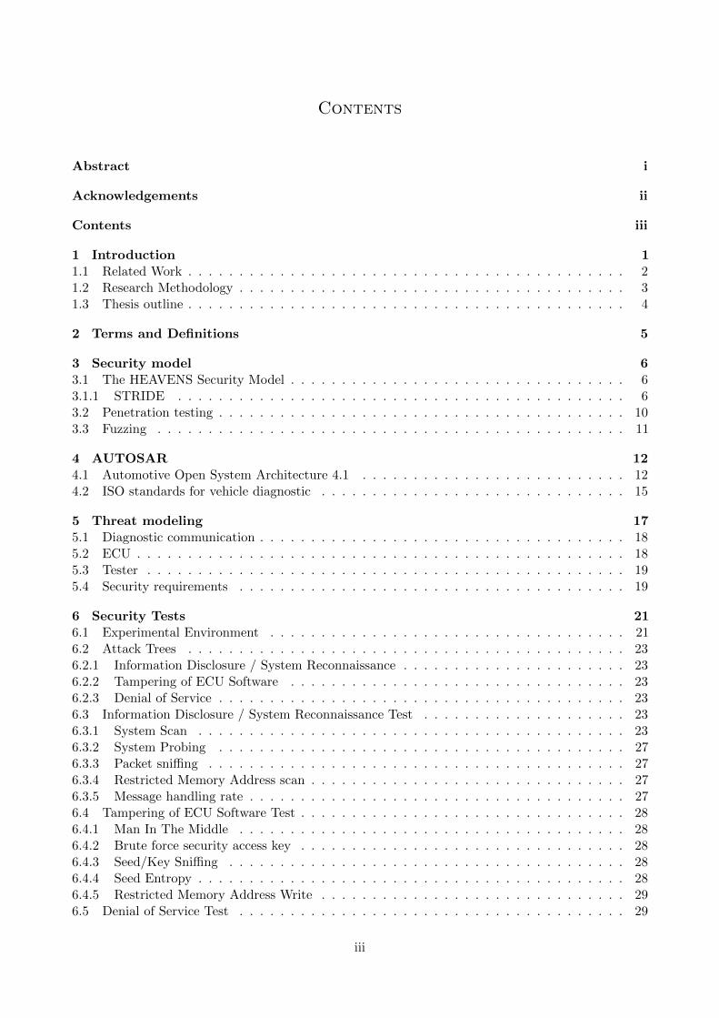
At the bottom of the architecture is the Basic Software Layer (BSW) which acts like a base to buildservice specific software on, see Figure 1.1. The BSW includes the standardized software such asthe Operating System, the Memory Manager and the Diagnostic module that are necessary for thesystem to work.
Figure 1.1: The layered AUTOSAR architecture
The Diagnostic module in the BSW layer is responsible for the communication between the vehiclesoftware and the manufacturer. The Diagnostic module is used to manage, update and reprogramthe components that are running inside the ECU, which makes the module an attractive target foradversaries. If unauthorized access is granted, an adversary could be able to reprogram the softwareand possibly endanger the safety of the vehicle’s passengers.
This thesis aims to evaluate the security of the standardized Diagnostic module of AUTOSAR, leadingto the following research questions.
• What vulnerabilities can be found in the AUTOSAR diagnostics Basic Softwaremodule?
• What are the possible threats and risks of these vulnerabilities?
1
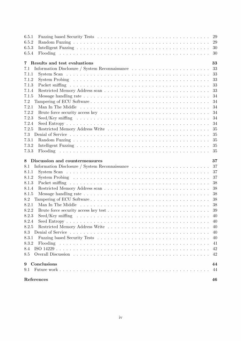
Figure 1.2: Simplified Microsoft Secure Development Lifecycle. [23]
• Can the vulnerabilities be mitigated and the security be improved?
This thesis is a part of the HEAVENS project that aims to create a common strategy to identifyvulnerabilities and define methodologies to evaluate security inside vehicles electrical and electronicssystem [31].
Previous parts of the project have included creating a threat model and declaring a common view ofhow to address security (see Section 3.1), and this thesis follows the HEAVENS terminology [14].
This thesis investigates the security of the AUTOSAR architecture Diagnostic Module, it evaluateshow security vulnerabilities are related to threats and safety risks. Proof of concept security tests ofthe found vulnerabilities are shown, and as such this thesis fits into the Verification step of MicrosoftsSecure Development Lifecycle (SDL) (see Figure 1.2).
1.1 Related Work
Vehicular security has gained some focus in recent years, and much academic research has been doneon the subject. Many security protocol implementations have been suggested to secure the onboardnetwork of a vehicle. Both software and hardware modules have been shown to mitigate the securityvulnerabilities of the advanced electronic devices present in today’s vehicles [11]. Most of the researchdone has been to reduce the threat of an external adversary, but less research has been done onvulnerabilities exploited by an internal adversary. A typical example is where a vehicle owner whoexploits vulnerabilities to gain access to restricted features of the vehicle, such as more engine power,without paying for the feature.
In Securing Vehicle Diagnostics in Repair Shops, Kleberger and Olovsson [19] describe suggestionson how to secure both wired and wireless remote diagnostic inside a repair shop. They suggest thatwell known security protocols for secure data transmission over LAN:s and internet (such as IPsec,SLL, Certificates and PKI) can be used to secure remote vehicle diagnostics. They also conclude thatIPsec is the most desirable security architecture to achieve secure diagnostics and that it additionallyincludes the possibility to perform secure diagnostics over the Internet. Their focus is on the commu-nication with an ECU, whereas our thesis focuses on vulnerabilities inside the ECUs diagnostics module.
Koscher et al. [20] wrote a widely cited paper in 2010 that included multiple frightening scenarios ofthe lack of security in vehicles at that time. Their work included defining a threat model, and anexperimental analysis on both stationary and moving targets.
2
Bayer et al. [4] wrote a paper providing insight on some motivations and possible attacks on automo-tive systems, as well as a theoretical evaluation of penetration testing techniques. We feel that theirwork misses a more practical approach, however, some of their ideas will be the foundation for ourtesting.
Vyleta [42] presented a thesis in which they did some security fuzz-testing on a simulated ECU. Thetests were conducted on only two services available in the DCM: WriteMemory and RequestDownload.Our thesis presents tests made on hardware using a real implementation, and includes more services.
This shows that researchers have been aware of the problem with security in the automotive industryfor quite some time, but new standards still doesn’t include security in a complete way. As pointedout by Kleberger and Olovsson [19] some existing standards have even removed previously presentsecurity ”best-practices”.
1.2 Research Methodology
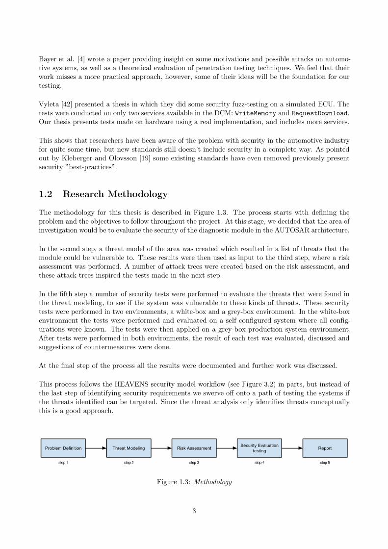
The methodology for this thesis is described in Figure 1.3. The process starts with defining theproblem and the objectives to follow throughout the project. At this stage, we decided that the area ofinvestigation would be to evaluate the security of the diagnostic module in the AUTOSAR architecture.
In the second step, a threat model of the area was created which resulted in a list of threats that themodule could be vulnerable to. These results were then used as input to the third step, where a riskassessment was performed. A number of attack trees were created based on the risk assessment, andthese attack trees inspired the tests made in the next step.
In the fifth step a number of security tests were performed to evaluate the threats that were found inthe threat modeling, to see if the system was vulnerable to these kinds of threats. These securitytests were performed in two environments, a white-box and a grey-box environment. In the white-boxenvironment the tests were performed and evaluated on a self configured system where all config-urations were known. The tests were then applied on a grey-box production system environment.After tests were performed in both environments, the result of each test was evaluated, discussed andsuggestions of countermeasures were done.
At the final step of the process all the results were documented and further work was discussed.
This process follows the HEAVENS security model workflow (see Figure 3.2) in parts, but instead ofthe last step of identifying security requirements we swerve off onto a path of testing the systems ifthe threats identified can be targeted. Since the threat analysis only identifies threats conceptuallythis is a good approach.
Figure 1.3: Methodology
3

1.3 Thesis outline
The rest of this thesis is structured as follows: chapter 2 contains a list of terms and definitions used,chapter 3 introduces security concepts, chapter 4 treats basic concepts used later on in the thesis.Chapter 5 contains the threat model of the system on which the tests were made, chapter 6 presentsthe tests made. Chapter 7 presents results and an evaluation of them. Chapters 8 and 9 contains adiscussion and our conclusions.
4
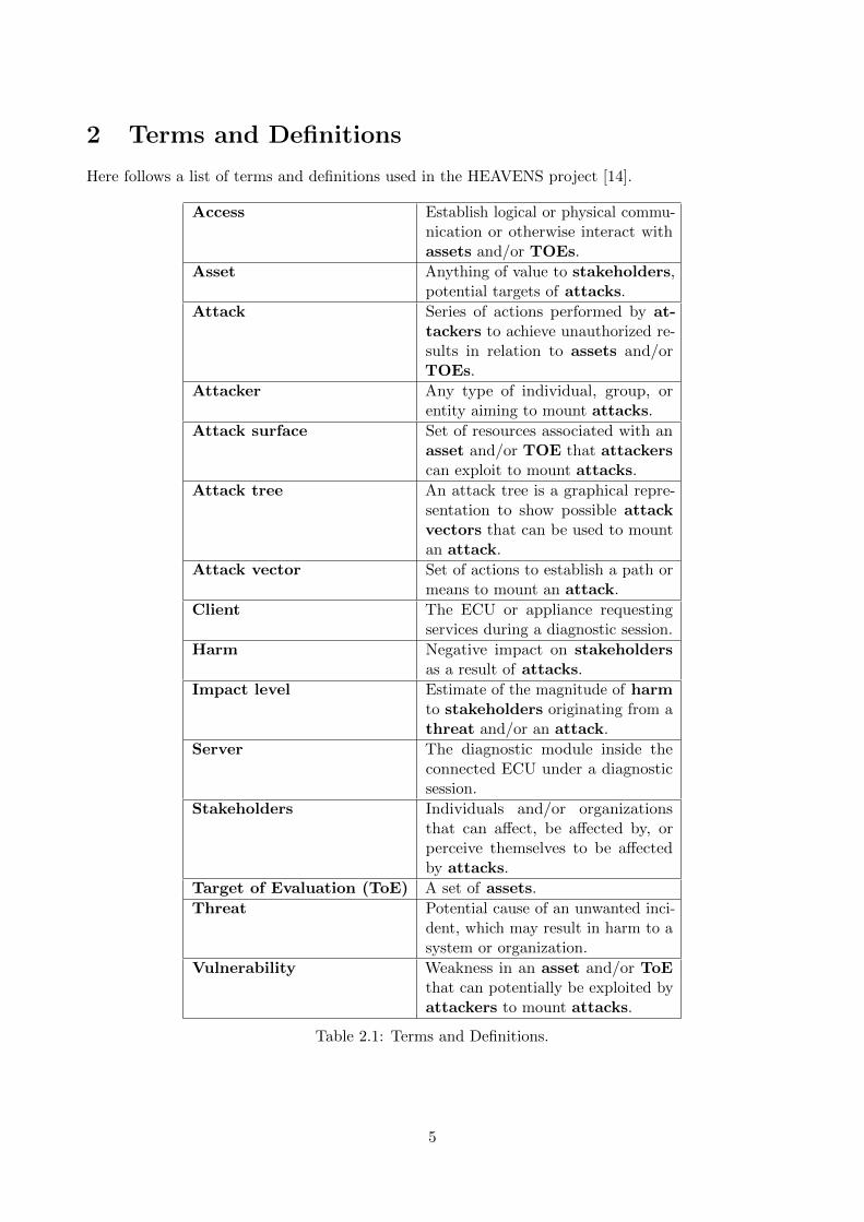
2 Terms and Definitions
Here follows a list of terms and definitions used in the HEAVENS project [14].
Access Establish logical or physical commu-nication or otherwise interact withassets and/or TOEs.
Asset Anything of value to stakeholders,potential targets of attacks.
Attack Series of actions performed by at-tackers to achieve unauthorized re-sults in relation to assets and/orTOEs.
Attacker Any type of individual, group, orentity aiming to mount attacks.
Attack surface Set of resources associated with anasset and/or TOE that attackerscan exploit to mount attacks.
Attack tree An attack tree is a graphical repre-sentation to show possible attackvectors that can be used to mountan attack.
Attack vector Set of actions to establish a path ormeans to mount an attack.
Client The ECU or appliance requestingservices during a diagnostic session.
Harm Negative impact on stakeholdersas a result of attacks.
Impact level Estimate of the magnitude of harmto stakeholders originating from athreat and/or an attack.
Server The diagnostic module inside theconnected ECU under a diagnosticsession.
Stakeholders Individuals and/or organizationsthat can affect, be affected by, orperceive themselves to be affectedby attacks.
Target of Evaluation (ToE) A set of assets.
Threat Potential cause of an unwanted inci-dent, which may result in harm to asystem or organization.
Vulnerability Weakness in an asset and/or ToEthat can potentially be exploited byattackers to mount attacks.
Table 2.1: Terms and Definitions.
5
3 Security model
This chapter introduces the risk assessment and threat analysis processes used in the HEAVENSsecurity model. Sections 3.2 and 3.3 introduces different kinds of penetration testing and fuzz testingtechniques used to verify the conceptual findings from the threat analysis.
3.1 The HEAVENS Security Model
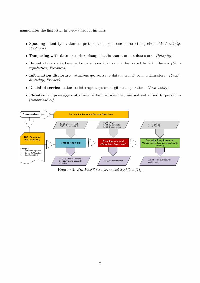
The workflow for the HEAVENS security model can be seen in Figure 3.2 and consists of four modules:defining the target of evaluation, threat analysis, risk assessment, and identifying security requirements.
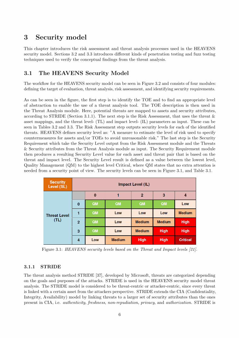
As can be seen in the figure, the first step is to identify the TOE and to find an appropriate levelof abstraction to enable the use of a threat analysis tool. The TOE description is then used inthe Threat Analysis module. Here, potential threats are mapped to assets and security attributes,according to STRIDE (Section 3.1.1). The next step is the Risk Assessment, that uses the threat &asset mappings, and the threat level- (TL) and impact level- (IL) parameters as input. These can beseen in Tables 3.2 and 3.3. The Risk Assessment step outputs security levels for each of the identifiedthreats. HEAVENS defines security level as: ”A measure to estimate the level of risk used to specifycountermeasures for assets and/or TOEs to avoid unreasonable risk.” The last step is the SecurityRequirement which take the Security Level output from the Risk Assessment module and the Threats& Security attributes from the Threat Analysis module as input. The Security Requirement modulethen produces a resulting Security Level value for each asset and threat pair that is based on thethreat and impact level. The Security Level result is defined as a value between the lowest level,Quality Management (QM) to the highest level Critical, where QM states that no extra attention isneeded from a security point of view. The security levels can be seen in Figure 3.1, and Table 3.1.
Figure 3.1: HEAVENS security levels based on the Threat and Impact levels [21].
3.1.1 STRIDE
The threat analysis method STRIDE [37], developed by Microsoft, threats are categorized dependingon the goals and purposes of the attacks. STRIDE is used in the HEAVENS security model threatanalysis. The STRIDE model is considered to be threat-centric or attacker-centric, since every threatis linked with a certain asset from the attackers perspective. STRIDE extends the CIA (Confidentiality,Integrity, Availability) model by linking threats to a larger set of security attributes than the onespresent in CIA, i.e. authenticity, freshness, non-repudiation, privacy, and authorization. STRIDE is
6
named after the first letter in every threat it includes.
• Spoofing identity - attackers pretend to be someone or something else - (Authenticity,Freshness)
• Tampering with data - attackers change data in transit or in a data store - (Integrity)
• Repudiation - attackers performs actions that cannot be traced back to them - (Non-repudiation, Freshness)
• Information disclosure - attackers get access to data in transit or in a data store - (Confi-dentiality, Privacy)
• Denial of service - attackers interrupt a systems legitimate operation - (Availability)
• Elevation of privilege - attackers perform actions they are not authorized to perform -(Authorization)
Figure 3.2: HEAVENS security model workflow [21].
7
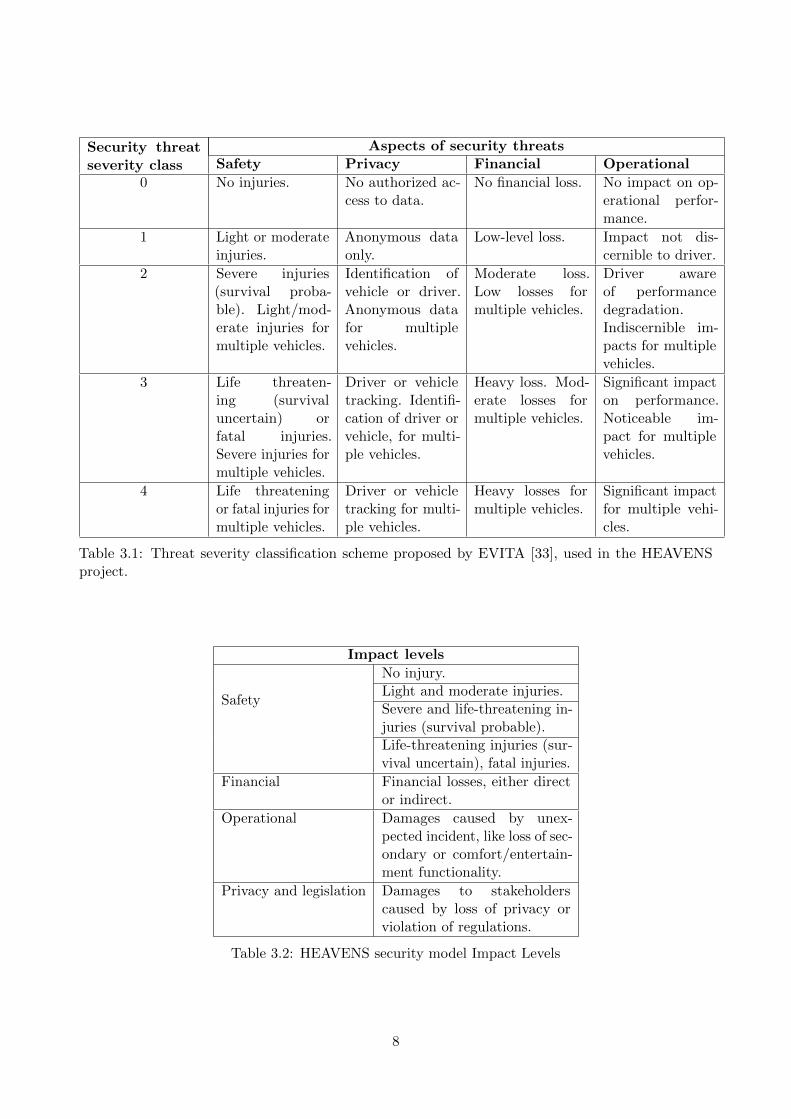
Security threatseverity class
Aspects of security threatsSafety Privacy Financial Operational
0 No injuries. No authorized ac-cess to data.
No financial loss. No impact on op-erational perfor-mance.
1 Light or moderateinjuries.
Anonymous dataonly.
Low-level loss. Impact not dis-cernible to driver.
2 Severe injuries(survival proba-ble). Light/mod-erate injuries formultiple vehicles.
Identification ofvehicle or driver.Anonymous datafor multiplevehicles.
Moderate loss.Low losses formultiple vehicles.
Driver awareof performancedegradation.Indiscernible im-pacts for multiplevehicles.
3 Life threaten-ing (survivaluncertain) orfatal injuries.Severe injuries formultiple vehicles.
Driver or vehicletracking. Identifi-cation of driver orvehicle, for multi-ple vehicles.
Heavy loss. Mod-erate losses formultiple vehicles.
Significant impacton performance.Noticeable im-pact for multiplevehicles.
4 Life threateningor fatal injuries formultiple vehicles.
Driver or vehicletracking for multi-ple vehicles.
Heavy losses formultiple vehicles.
Significant impactfor multiple vehi-cles.
Table 3.1: Threat severity classification scheme proposed by EVITA [33], used in the HEAVENSproject.
Impact levels
Safety
No injury.Light and moderate injuries.Severe and life-threatening in-juries (survival probable).Life-threatening injuries (sur-vival uncertain), fatal injuries.
Financial Financial losses, either director indirect.
Operational Damages caused by unex-pected incident, like loss of sec-ondary or comfort/entertain-ment functionality.
Privacy and legislation Damages to stakeholderscaused by loss of privacy orviolation of regulations.
Table 3.2: HEAVENS security model Impact Levels
8
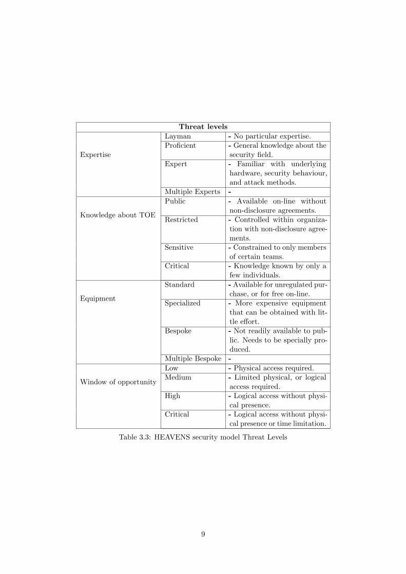
Threat levels
Expertise
Layman - No particular expertise.Proficient - General knowledge about the
security field.Expert - Familiar with underlying
hardware, security behaviour,and attack methods.
Multiple Experts -
Knowledge about TOE
Public - Available on-line withoutnon-disclosure agreements.
Restricted - Controlled within organiza-tion with non-disclosure agree-ments.
Sensitive - Constrained to only membersof certain teams.
Critical - Knowledge known by only afew individuals.
Equipment
Standard - Available for unregulated pur-chase, or for free on-line.
Specialized - More expensive equipmentthat can be obtained with lit-tle effort.
Bespoke - Not readily available to pub-lic. Needs to be specially pro-duced.
Multiple Bespoke -
Window of opportunity
Low - Physical access required.Medium - Limited physical, or logical
access required.High - Logical access without physi-
cal presence.Critical - Logical access without physi-
cal presence or time limitation.
Table 3.3: HEAVENS security model Threat Levels
9
3.2 Penetration testing
Penetration testing is a non-malicious process in which the goal is to find vulnerabilities in a systemor a software. This is usually done by analyzing the system using some tool, for example OpenVASused to analyze network vulnerabilities [27]. Tools like OpenVAS will produce a report specifyingwhat services (and versions of them) are available on the TOE and what vulnerabilities are presentfor the versions of the services available. When the system has been identified the penetration testercan use known attacks on the systems assets and access points.
The first step of a penetration test is reconnaissance, to determine what interfaces and specificationswould be open to a potential attacker. The second step could be to mount small scale attacks on someexternal interfaces. In a web server one such interface could be an open port, and in an automotivesetting it could be the CAN bus [4].
Penetration testing is divided into three main categories, Black-box, White-box and Grey-box dependingon the amount of information that the attacker has about the target [24].
White-box testing technique is a technique where the tester has full knowledge of the internalarchitecture of the system and has full access to the software source code. This technique give adetailed test of the internal logic and the code structure of the system. By testing the system withthis approach implementation errors such as poor key and cryptographic algorithms can be revealed.
Black-box is a testing technique where the tester instead has no knowledge about the source codeand how the internal system is working. Here the tester only has access to the external interfacesthat are available from the software.
Grey-box is a technique where the black- and the white-box techniques are combined. Here thetests are performed without access to the source code but with fundamental knowledge of the systemsoftware structure.
The different techniques have different advantages and disadvantages. The White-box technique hasthe advantage of giving a full coverage of the tested areas of the software and can also find unusedcode that is still present. This techniques is however expensive and need the tester to be highly skilledof the tested software.
The advantage of the Black-box is that the tester knows less about the system and that the develop-ment of tests are quicker. The disadvantages of this approach is however that the testing becomesinefficient and only a limited number of scenarios are covered.
In the Grey-box technique the benefits of both the white- and the black-box approaches are combined.Here the tester can rely on the interface definitions and the system functions rather than focuson gaining a deeper understanding of the source code. In this technique the tester can create wellspecified test scenarios that are tested from the user, attacker, point of view instead of the developersview.
The Grey-box has the same disadvantage as the black-box, where the coverage of the test are limitedas the source code is unavailable when the designing the tests are done. Many data flow path mayalso be untested due to the same reason.
10
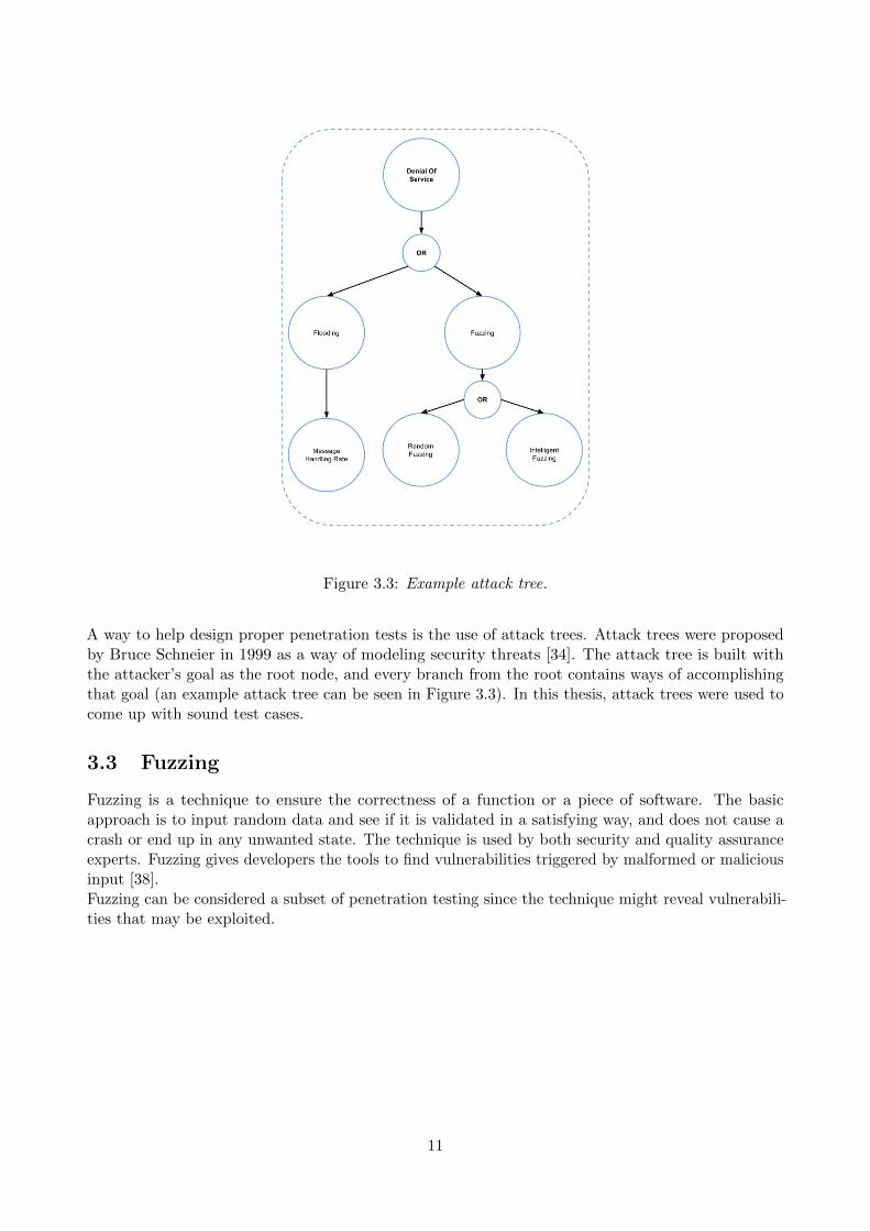
Figure 3.3: Example attack tree.
A way to help design proper penetration tests is the use of attack trees. Attack trees were proposedby Bruce Schneier in 1999 as a way of modeling security threats [34]. The attack tree is built withthe attacker’s goal as the root node, and every branch from the root contains ways of accomplishingthat goal (an example attack tree can be seen in Figure 3.3). In this thesis, attack trees were used tocome up with sound test cases.
3.3 Fuzzing
Fuzzing is a technique to ensure the correctness of a function or a piece of software. The basicapproach is to input random data and see if it is validated in a satisfying way, and does not cause acrash or end up in any unwanted state. The technique is used by both security and quality assuranceexperts. Fuzzing gives developers the tools to find vulnerabilities triggered by malformed or maliciousinput [38].Fuzzing can be considered a subset of penetration testing since the technique might reveal vulnerabili-ties that may be exploited.
11
4 AUTOSAR
This chapter introduces concepts that are important to this thesis. It starts by describing theAUTOSAR architecture and then quickly narrows down towards the Diagnostic module and how thecommunication for the diagnostic module is standardized.
4.1 Automotive Open System Architecture 4.1
The Automotive Open System Architecture (AUTOSAR) is an alliance of vehicle manufacturers andautomotive suppliers with the purpose to develop an open industry standard software architecturefor the automotive E/E systems. The standardization of automotive electronic development byAUTOSAR aids to remove the previously used OEM specific standards and reduce the need for everysupplier to develop their own software architecture. The standardization is intended to reduce thelarge development cost and remove the need of a large number of tools and communication protocolsthat was needed by the suppliers earlier. The aim of AUTOSAR is to change the development ofnew software application from coding based to configuration based development. This allows thedevelopers to focus more on the innovation process of new functions instead of the OEM specificstandard configuration coding for each new software.
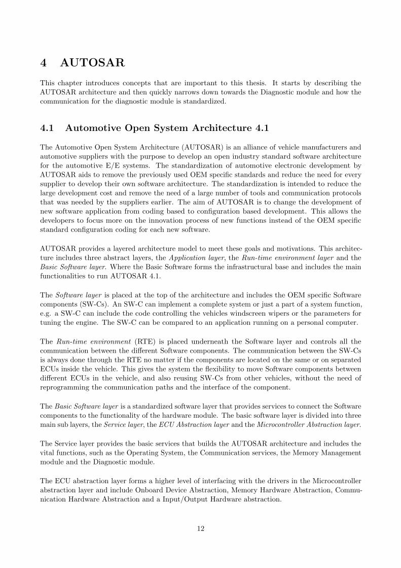
AUTOSAR provides a layered architecture model to meet these goals and motivations. This architec-ture includes three abstract layers, the Application layer, the Run-time environment layer and theBasic Software layer. Where the Basic Software forms the infrastructural base and includes the mainfunctionalities to run AUTOSAR 4.1.
The Software layer is placed at the top of the architecture and includes the OEM specific Softwarecomponents (SW-Cs). An SW-C can implement a complete system or just a part of a system function,e.g. a SW-C can include the code controlling the vehicles windscreen wipers or the parameters fortuning the engine. The SW-C can be compared to an application running on a personal computer.
The Run-time environment (RTE) is placed underneath the Software layer and controls all thecommunication between the different Software components. The communication between the SW-Csis always done through the RTE no matter if the components are located on the same or on separatedECUs inside the vehicle. This gives the system the flexibility to move Software components betweendifferent ECUs in the vehicle, and also reusing SW-Cs from other vehicles, without the need ofreprogramming the communication paths and the interface of the component.
The Basic Software layer is a standardized software layer that provides services to connect the Softwarecomponents to the functionality of the hardware module. The basic software layer is divided into threemain sub layers, the Service layer, the ECU Abstraction layer and the Microcontroller Abstraction layer.
The Service layer provides the basic services that builds the AUTOSAR architecture and includes thevital functions, such as the Operating System, the Communication services, the Memory Managementmodule and the Diagnostic module.
The ECU abstraction layer forms a higher level of interfacing with the drivers in the Microcontrollerabstraction layer and include Onboard Device Abstraction, Memory Hardware Abstraction, Commu-nication Hardware Abstraction and a Input/Output Hardware abstraction.
12
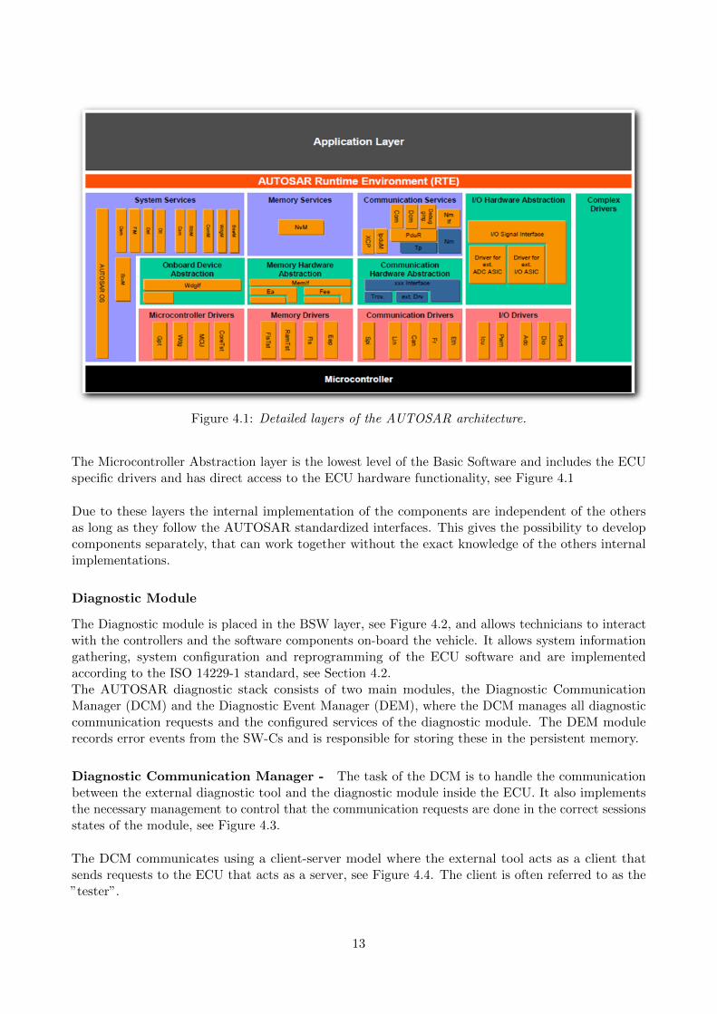
Figure 4.1: Detailed layers of the AUTOSAR architecture.
The Microcontroller Abstraction layer is the lowest level of the Basic Software and includes the ECUspecific drivers and has direct access to the ECU hardware functionality, see Figure 4.1
Due to these layers the internal implementation of the components are independent of the othersas long as they follow the AUTOSAR standardized interfaces. This gives the possibility to developcomponents separately, that can work together without the exact knowledge of the others internalimplementations.
Diagnostic Module
The Diagnostic module is placed in the BSW layer, see Figure 4.2, and allows technicians to interactwith the controllers and the software components on-board the vehicle. It allows system informationgathering, system configuration and reprogramming of the ECU software and are implementedaccording to the ISO 14229-1 standard, see Section 4.2.The AUTOSAR diagnostic stack consists of two main modules, the Diagnostic CommunicationManager (DCM) and the Diagnostic Event Manager (DEM), where the DCM manages all diagnosticcommunication requests and the configured services of the diagnostic module. The DEM modulerecords error events from the SW-Cs and is responsible for storing these in the persistent memory.
Diagnostic Communication Manager - The task of the DCM is to handle the communicationbetween the external diagnostic tool and the diagnostic module inside the ECU. It also implementsthe necessary management to control that the communication requests are done in the correct sessionsstates of the module, see Figure 4.3.
The DCM communicates using a client-server model where the external tool acts as a client thatsends requests to the ECU that acts as a server, see Figure 4.4. The client is often referred to as the”tester”.
13
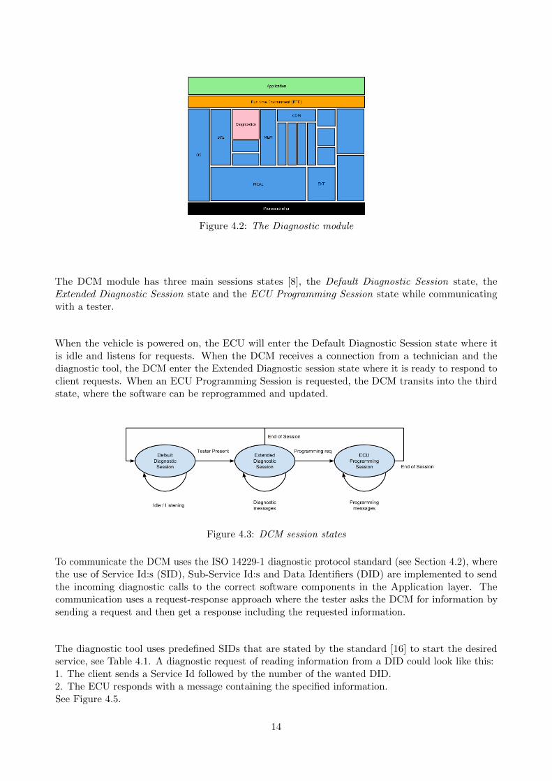
Figure 4.2: The Diagnostic module
The DCM module has three main sessions states [8], the Default Diagnostic Session state, theExtended Diagnostic Session state and the ECU Programming Session state while communicatingwith a tester.
When the vehicle is powered on, the ECU will enter the Default Diagnostic Session state where itis idle and listens for requests. When the DCM receives a connection from a technician and thediagnostic tool, the DCM enter the Extended Diagnostic session state where it is ready to respond toclient requests. When an ECU Programming Session is requested, the DCM transits into the thirdstate, where the software can be reprogrammed and updated.
Figure 4.3: DCM session states
To communicate the DCM uses the ISO 14229-1 diagnostic protocol standard (see Section 4.2), wherethe use of Service Id:s (SID), Sub-Service Id:s and Data Identifiers (DID) are implemented to sendthe incoming diagnostic calls to the correct software components in the Application layer. Thecommunication uses a request-response approach where the tester asks the DCM for information bysending a request and then get a response including the requested information.
The diagnostic tool uses predefined SIDs that are stated by the standard [16] to start the desiredservice, see Table 4.1. A diagnostic request of reading information from a DID could look like this:1. The client sends a Service Id followed by the number of the wanted DID.2. The ECU responds with a message containing the specified information.See Figure 4.5.
14
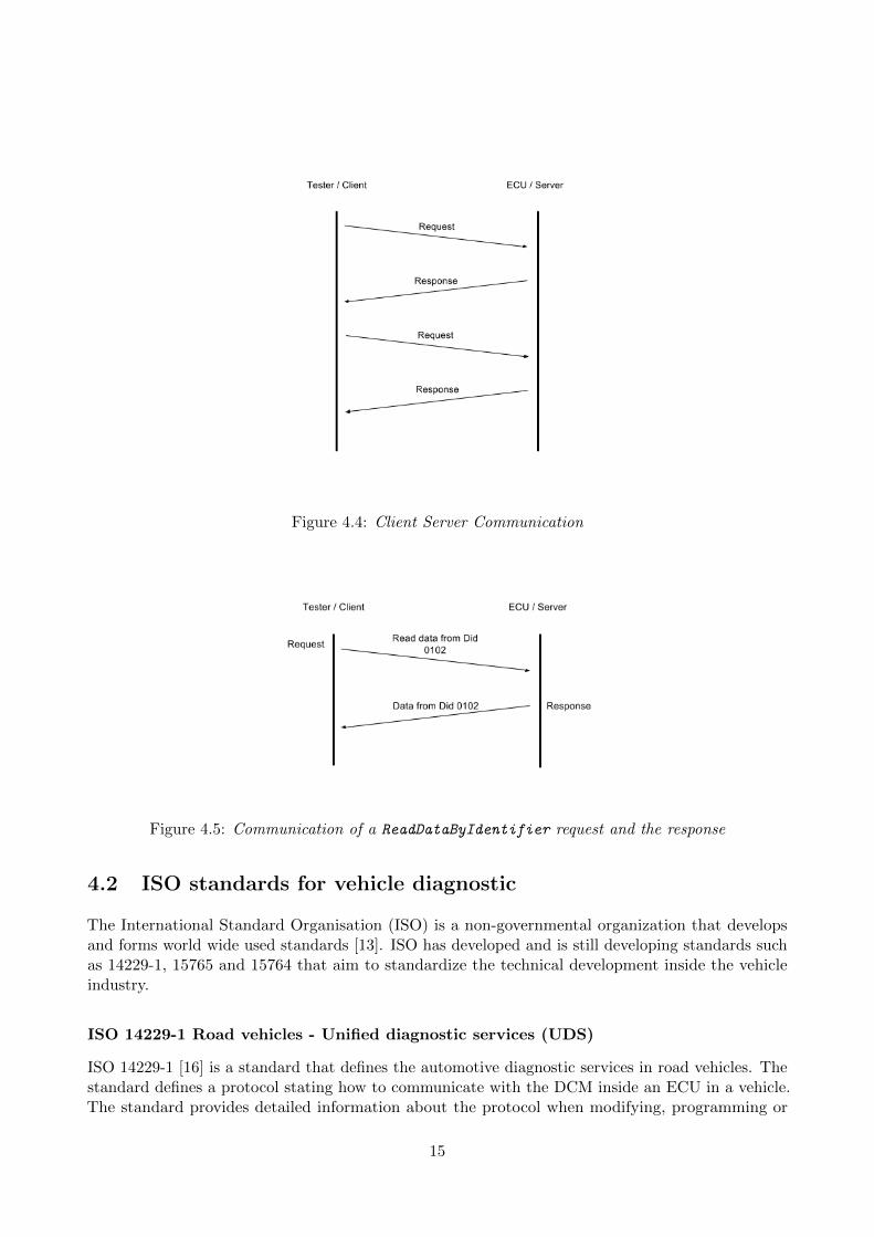
Figure 4.4: Client Server Communication
Figure 4.5: Communication of a ReadDataByIdentifier request and the response
4.2 ISO standards for vehicle diagnostic
The International Standard Organisation (ISO) is a non-governmental organization that developsand forms world wide used standards [13]. ISO has developed and is still developing standards suchas 14229-1, 15765 and 15764 that aim to standardize the technical development inside the vehicleindustry.
ISO 14229-1 Road vehicles - Unified diagnostic services (UDS)
ISO 14229-1 [16] is a standard that defines the automotive diagnostic services in road vehicles. Thestandard defines a protocol stating how to communicate with the DCM inside an ECU in a vehicle.The standard provides detailed information about the protocol when modifying, programming or
15
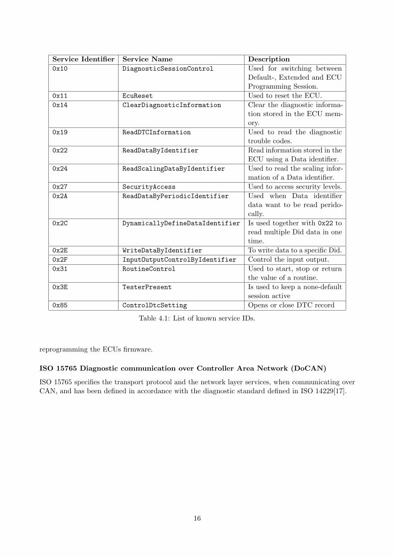
Service Identifier Service Name Description
0x10 DiagnosticSessionControl Used for switching betweenDefault-, Extended and ECUProgramming Session.
0x11 EcuReset Used to reset the ECU.
0x14 ClearDiagnosticInformation Clear the diagnostic informa-tion stored in the ECU mem-ory.
0x19 ReadDTCInformation Used to read the diagnostictrouble codes.
0x22 ReadDataByIdentifier Read information stored in theECU using a Data identifier.
0x24 ReadScalingDataByIdentifier Used to read the scaling infor-mation of a Data identifier.
0x27 SecurityAccess Used to access security levels.
0x2A ReadDataByPeriodicIdentifier Used when Data identifierdata want to be read perido-cally.
0x2C DynamicallyDefineDataIdentifier Is used together with 0x22 toread multiple Did data in onetime.
0x2E WriteDataByIdentifier To write data to a specific Did.
0x2F InputOutputControlByIdentifier Control the input output.
0x31 RoutineControl Used to start, stop or returnthe value of a routine.
0x3E TesterPresent Is used to keep a none-defaultsession active
0x85 ControlDtcSetting Opens or close DTC record
Table 4.1: List of known service IDs.
reprogramming the ECUs firmware.
ISO 15765 Diagnostic communication over Controller Area Network (DoCAN)
ISO 15765 specifies the transport protocol and the network layer services, when communicating overCAN, and has been defined in accordance with the diagnostic standard defined in ISO 14229[17].
16
5 Threat modeling
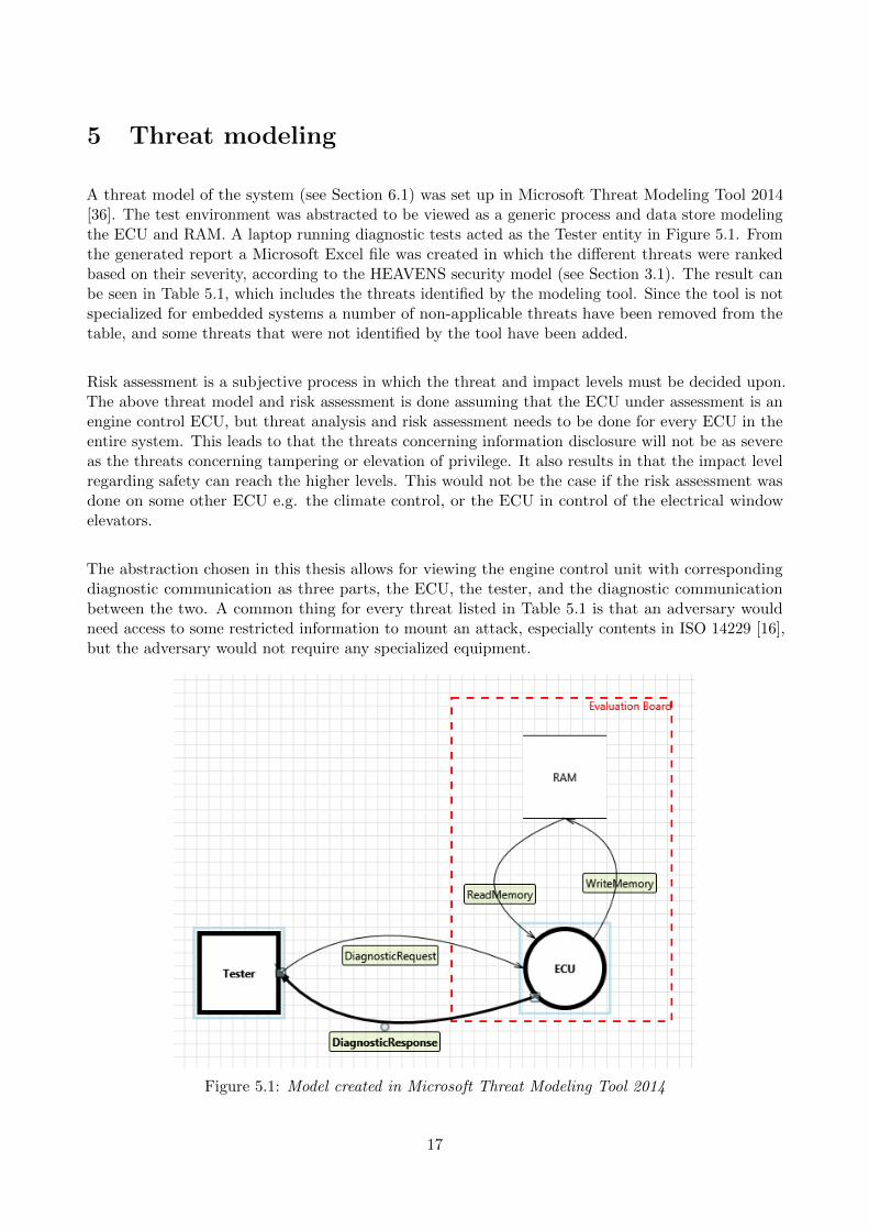
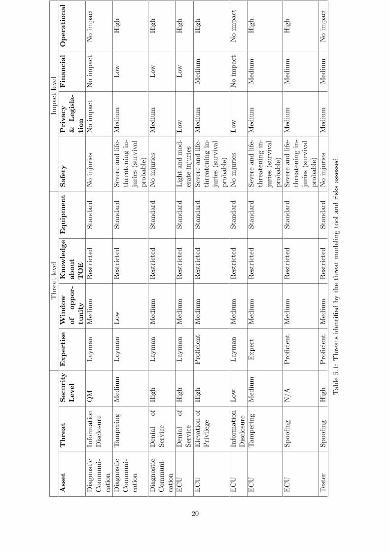
A threat model of the system (see Section 6.1) was set up in Microsoft Threat Modeling Tool 2014[36]. The test environment was abstracted to be viewed as a generic process and data store modelingthe ECU and RAM. A laptop running diagnostic tests acted as the Tester entity in Figure 5.1. Fromthe generated report a Microsoft Excel file was created in which the different threats were rankedbased on their severity, according to the HEAVENS security model (see Section 3.1). The result canbe seen in Table 5.1, which includes the threats identified by the modeling tool. Since the tool is notspecialized for embedded systems a number of non-applicable threats have been removed from thetable, and some threats that were not identified by the tool have been added.
Risk assessment is a subjective process in which the threat and impact levels must be decided upon.The above threat model and risk assessment is done assuming that the ECU under assessment is anengine control ECU, but threat analysis and risk assessment needs to be done for every ECU in theentire system. This leads to that the threats concerning information disclosure will not be as severeas the threats concerning tampering or elevation of privilege. It also results in that the impact levelregarding safety can reach the higher levels. This would not be the case if the risk assessment wasdone on some other ECU e.g. the climate control, or the ECU in control of the electrical windowelevators.
The abstraction chosen in this thesis allows for viewing the engine control unit with correspondingdiagnostic communication as three parts, the ECU, the tester, and the diagnostic communicationbetween the two. A common thing for every threat listed in Table 5.1 is that an adversary wouldneed access to some restricted information to mount an attack, especially contents in ISO 14229 [16],but the adversary would not require any specialized equipment.
Figure 5.1: Model created in Microsoft Threat Modeling Tool 2014
17
5.1 Diagnostic communication
There are three threats linked to the diagnostic communication: information disclosure, denial ofservice, and tampering.
Information disclosure From the risk assessment done, it can be seen that information disclosurefrom the diagnostic communication does not pose a serious risk, even though an adversary does notneed any particular skills or non-standard equipment. It receives such a low security level because ofthe low impact levels, there are no impacts to either safety, privacy, financial, nor operational categories.
Tampering The tampering threat receives a higher security level. The tampering of the diagnosticscommunication might result in changed engine control parameters that can lead to involuntarilyacceleration or other consequences of that sort. Involuntary acceleration can of course lead to safetyissues, it might lead to legislative issues for the stakeholders, and it of course can lead to a highoperational impact since the driver might lose control of the vehicle.
Denial of service Denial of service of the diagnostic communication could be done by cuttingcables, which means that no expertise is necessary for an adversary realize the threat. It would mostlikely not result in any impact on safety, but it could result in damage to the vehicle. Assume forexample that no error messages are shown when oil level was low for a long period of time withoutany stakeholders knowledge.
5.2 ECU
Five threats are connected to the ECU asset.
Denial of service Denial of service of the ECU results in a high security level. Having the enginecontrol ECU unreachable might lead to the vehicle stopping in unsuitable places and could potentiallylead to minor injuries. The operational impact level however is set to high since the engine controlwill no longer work. The security level reaches a high level since an adversary does not require anyspecific expertise to realize this threat.
Elevation of privilege A threat concerning elevation of privilege has been identified and rankedhigh on the security level scale. If an adversary were to gain elevated privileges on the engine controlECU we would see impacts similar to that of the tampering with the diagnostics communication werethe adversary could potentially modify engine control parameters resulting in unwanted behaviour ofthe vehicle and potential harm to persons in and around it.
Information disclosure The information disclosure threat on the ECU asset does not pose anyparticular risk, it receives a low security level rating. It would most likely not result in any injuries orhave any operational impact.
18
Tampering Tampering with the engine control ECU would require expert knowledge, and includesreprogramming it. If successful, the results would be similar to the tampering of diagnostic communi-cation, with severe injuries and high operational impact. It could also potentially lead to legislativerepercussions for the stakeholders and therefore also have financial impact.
Spoofing Spoofing the ECU into thinking the adversary is a legitimate tester could potentiallyallow the adversary to change engine control parameters. This would have similar impact to tam-pering with the ECU, or gaining elevated privileges, resulting in severe injuries and operational impact.
5.3 Tester
Only one threat was identified against the tester asset. Spoofing the tester into thinking the adversaryis the engine control ECU would most likely not result in any injuries or have an operational impact,but could potentially have legislative and financial impact since measurements from the engine couldbe faked.
5.4 Security requirements
Assets with special security requirements can be identified from Table 5.1. In this specific case eachasset in the system has need of special security requirements, since each asset has at least one threatresulting in a higher than Quality Management (QM) security level [21].Since this is just a conceptual evaluation, it should be tested in practice as well to see if the threatsand risks have been assessed correctly. To do this, a number of tests have been designed, and executed(see Chapter 6).
19
Th
reat
level
Imp
act
level
Ass
et
Th
reat
Secu
rity
Level
Exp
ert
ise
Win
dow
of
op
por-
tun
ity
Kn
ow
led
ge
ab
ou
tT
OE
Equ
ipm
ent
Safe
tyP
rivacy
&L
egis
la-
tion
Fin
an
cia
lO
pera
tion
al
Dia
gn
ost
icC
om
mu
ni-
cati
on
Info
rmati
on
Dis
closu
reQ
ML
aym
anM
ediu
mR
estr
icte
dS
tan
dard
No
inju
ries
No
imp
act
No
imp
act
No
imp
act
Dia
gn
ost
icC
om
mu
ni-
cati
on
Tam
per
ing
Med
ium
Lay
man
Low
Res
tric
ted
Sta
nd
ard
Sev
ere
and
life
-th
reate
nin
gin
-ju
ries
(su
rviv
al
pro
bab
le)
Med
ium
Low
Hig
h
Dia
gn
ost
icC
om
mu
ni-
cati
on
Den
ial
of
Ser
vic
eH
igh
Lay
man
Med
ium
Res
tric
ted
Sta
nd
ard
No
inju
ries
Med
ium
Low
Hig
h
EC
UD
enia
lof
Ser
vic
eH
igh
Lay
man
Med
ium
Res
tric
ted
Sta
nd
ard
Lig
ht
and
mod-
erat
ein
juri
esL
owL
owH
igh
EC
UE
leva
tion
ofP
rivil
ege
Hig
hP
rofi
cien
tM
ediu
mR
estr
icte
dS
tan
dard
Sev
ere
and
life
-th
reate
nin
gin
-ju
ries
(su
rviv
al
pro
bab
le)
Med
ium
Med
ium
Hig
h
EC
UIn
form
ati
on
Dis
closu
reL
owL
aym
anM
ediu
mR
estr
icte
dS
tan
dard
No
inju
ries
Low
No
imp
act
No
imp
act
EC
UT
am
per
ing
Med
ium
Exp
ert
Med
ium
Res
tric
ted
Sta
nd
ard
Sev
ere
and
life
-th
reate
nin
gin
-ju
ries
(su
rviv
al
pro
bab
le)
Med
ium
Med
ium
Hig
h
EC
US
poofi
ng
N/A
Pro
fici
ent
Med
ium
Res
tric
ted
Sta
nd
ard
Sev
ere
and
life
-th
reate
nin
gin
-ju
ries
(su
rviv
al
pro
bab
le)
Med
ium
Med
ium
Hig
h
Tes
ter
Sp
oofi
ng
Hig
hP
rofi
cien
tM
ediu
mR
estr
icte
dS
tan
dard
No
inju
ries
Med
ium
Med
ium
No
imp
act
Tab
le5.1
:T
hre
ats
iden
tifi
edby
the
thre
atm
od
elin
gto
olan
dri
sks
asse
ssed
.
20
6 Security Tests
This section describes the tests that were done in this thesis work to evaluate if a system is vulnerable todifferent security threats and to see what information an attacker performing similar attacks could gain.
The test are describe here and the test results are described in Section 7. The outcome of the test arefurther described in Section 8.
The security evaluation tests were conducted on two systems. The first system was an evaluationboard running AUTOSAR 4.1.1 where we configured and implemented the running services thatconstitute the complete DCM system. This gave us the advantage of possessing all information aboutthe system. The second test system was a part of an existing production system. This system gave usthe ability to evaluate the security of a real system that is used in vehicles today.
The tests to evaluate the security vulnerabilities of the DCM module in the different systems areperformed using two approaches. On the evaluation board the tests were conducted in a white-boxenvironment (see Section 3.2). The production system could be seen as a grey-box system (Section3.2) due to that it complied to the ISO 14229-1 standard [16], which means that some informationabout how it would respond was already known.
The security tests are divided according to three root goals of an adversary extracted from the threatmodeling, see Section 5. The Information Disclosure / System Reconniassance, the Tampering of ECUsoftware and Denial of Service goal. How the tests are related to the adversary goals are describedand graphically shown in the following section, see Section 6.2 regarding attack trees.
6.1 Experimental Environment
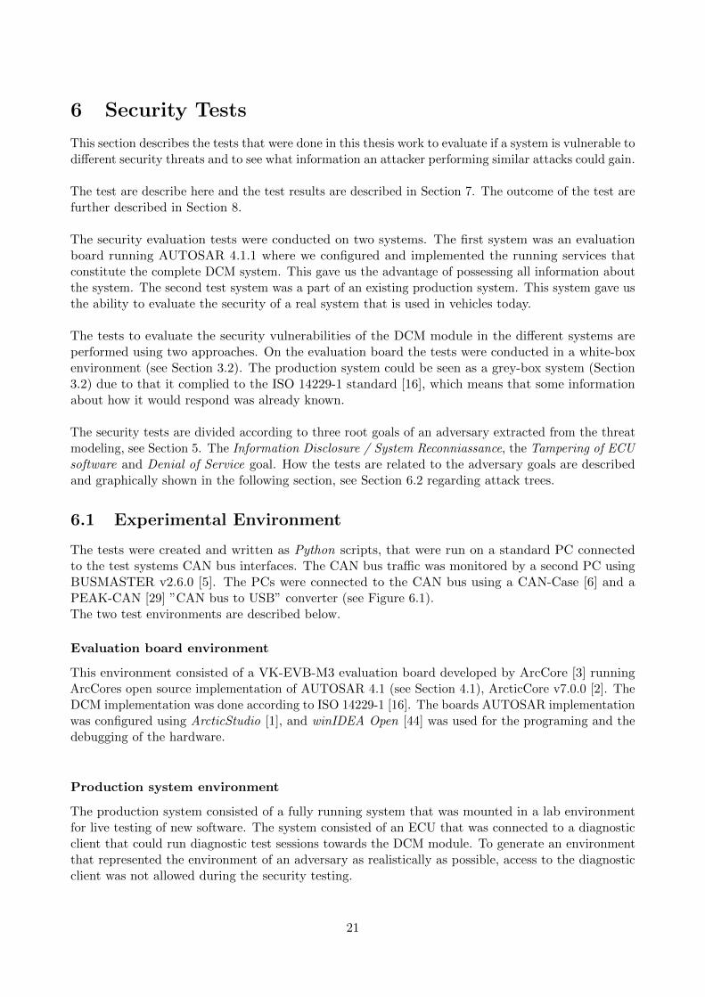
The tests were created and written as Python scripts, that were run on a standard PC connectedto the test systems CAN bus interfaces. The CAN bus traffic was monitored by a second PC usingBUSMASTER v2.6.0 [5]. The PCs were connected to the CAN bus using a CAN-Case [6] and aPEAK-CAN [29] ”CAN bus to USB” converter (see Figure 6.1).The two test environments are described below.
Evaluation board environment
This environment consisted of a VK-EVB-M3 evaluation board developed by ArcCore [3] runningArcCores open source implementation of AUTOSAR 4.1 (see Section 4.1), ArcticCore v7.0.0 [2]. TheDCM implementation was done according to ISO 14229-1 [16]. The boards AUTOSAR implementationwas configured using ArcticStudio [1], and winIDEA Open [44] was used for the programing and thedebugging of the hardware.
Production system environment
The production system consisted of a fully running system that was mounted in a lab environmentfor live testing of new software. The system consisted of an ECU that was connected to a diagnosticclient that could run diagnostic test sessions towards the DCM module. To generate an environmentthat represented the environment of an adversary as realistically as possible, access to the diagnosticclient was not allowed during the security testing.
21
Figure 6.1: Laptop connected to the evaluation board from ArcCore, using a PEAK CAN to USBadapter.
22
6.2 Attack Trees
In this section, attack trees based on the results from the threat modeling of the system are introduced,see Chapter 5. The attack trees gives a graphical representation of possible sequences of events thatcan be implemented by an adversary to achieve the root goal of an attack [35]. At the root of thetrees the main goals of the adversary are placed, then the trees branches shows possible attack vectorsto achieve it. At the bottom of the tree the leafs represent possible footholds for the adversary. Thesefootholds are presented as security tests and has been performed throughout this thesis work. Thetests are described in the following sections, see Sections 6.3, 6.4, 6.5.
6.2.1 Information Disclosure / System Reconnaissance
This attack tree represent the goal of an adversary trying to retrieve initial information of the system.Getting a view of the configured system is a top priority for an adversary to make qualified attacksand discover vulnerabilities present in the system. This attack tree contains three adverse actionsthat an adversary can attempt to gain information about the DCM module, see Figure 6.4. Eachof the actions can be used separately to disclose partial information, or can be combined to get analmost complete view of the system. The leaves contains four security tests to address the informationdisclosure threat. The tests are further described in Sections 6.3.1, 6.3.2, 6.3.3.
6.2.2 Tampering of ECU Software
The attack tree of this threat includes two main attack vectors that the adversary can use to tamperwith the ECU software, see Figure 6.3. The first vector is the left branch where the software uploadof new content is performed, and the second vector is the right branch where an adversary is ableto modify the memory of the ECU. At the bottom of the tree the adverse action to be able tocompromise the software are placed. The adversary’s action leafs are implemented as security tests,and are described in Sections 6.4.1, 6.4.2, 6.4.3, 6.4.4, 6.4.5.
6.2.3 Denial of Service
The Denial of Service threat resulted in a attack tree including two branches. The first branchincludes the possibility for an adversary to flood the DCM module, and the other branch covers thepossibility to send invalidly formed messages that could potentially result in that the module endup in an unresponsive state. In the first branch an adversary starts by getting information aboutthe request handling rate of the DCM module, see Section 6.3.5. The information is then used toperform a flooding attack, see Section 6.5.4. At the bottom of the second branch the adverse actionsis performed through two fuzzing tests, see Section 6.5.2, 6.5.3.
6.3 Information Disclosure / System Reconnaissance Test
This section describes the test derived from the bottom of the Information Disclosure / SystemReconnaissance attack tree adversary actions. It describe how the test was performed in this thesis toachieve the root goal at the top of the tree.
6.3.1 System Scan
The scan test is built in three steps, the service identifier-, the sub-service/data identifier- and theinput size step. The test takes advantage of the response codes that are specified in ISO 14229-1.
23
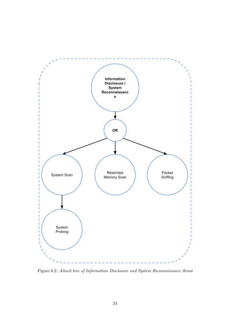
Figure 6.2: Attack tree of Information Disclosure and System Reconnaissance threat
24
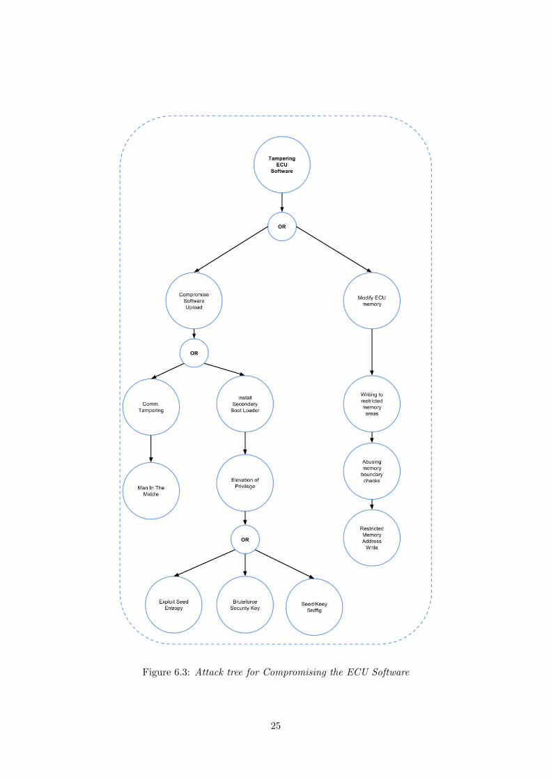
Figure 6.3: Attack tree for Compromising the ECU Software
25
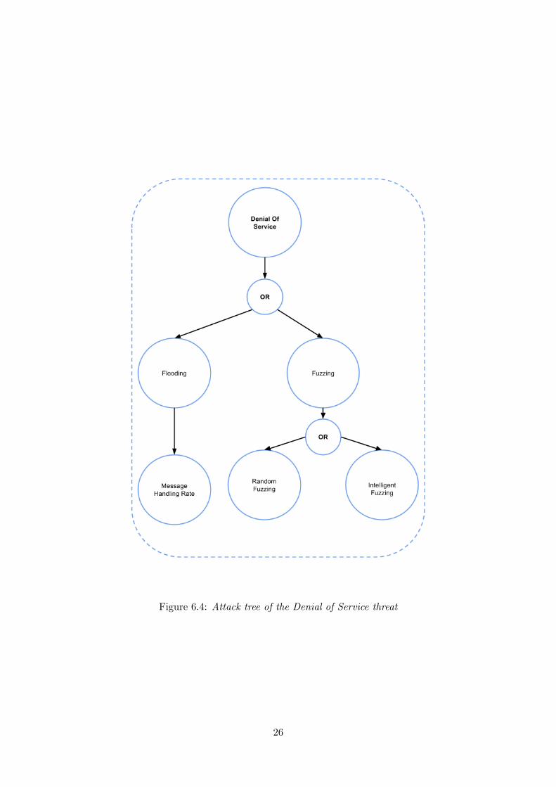
Figure 6.4: Attack tree of the Denial of Service threat
26
In the first step the test sends messages with all possible service ID numbers, the test is then able toverify if the service is present in the system or not depending on the response.In the second step the test uses information from step one to scan the running services for possible dataidentifiers. The scan sends messages with all possible data identifiers to the services and categorizesthe data identifiers in three categories:
• Present
• Present but not available in current security/session level
• Not present
In the final step of the test, different lengths of input is sent to each found data identifier and therequest depending on the service to find the expected length. The scan outputs a list of presentservices, their associated DIDs and the input length. The list can be seen as a mapping of the DCMstructure and can be used as input to the Intelligent Fuzzing test.
6.3.2 System Probing
The DCM module in each of the ECU:s has an identification number that acts as an address forcommunicating. The ISO 15765-1 states that the address of a module is a number between 0 and 2047.This test aims to find the identification number of the DCM module, that is used to communicate, byprobing the system [26]. The test is conducted by sending a DCM requested message towards all thepossible identification numbers in the system. If the test detects a proper DCM response message thetest logs the identification number and alerts the tester that a possible DCM module has been detected.
6.3.3 Packet sniffing
This test is used to find information about the system architecture and how the system is commu-nicating. It aims to find the identification numbers of the running modules and components of thesystem. This test is a compliment to the previous test 6.3.2 to find the identification number that theDCM module listens to during communication and how other non-DCM modules are addressed.
The test is conducted by connecting a node to the network that listens to the communication trafficfor DCM requests/responses and record the ID number used.Since the communication in vehicles today is unencrypted the test can also be used to find sensitiveinformation such as seed/key pairs that are used to unlock security levels.
6.3.4 Restricted Memory Address scan
This test aims to find out information about memory sections that are restricted for reading withoutsecurity access. If an area is restricted it can potentially contain the security access key, and couldmaybe be read if the binary file of the ECU could be extracted.
6.3.5 Message handling rate
This test aims to gather information about the DCMs ability to handle messages that are receivedat an unusual rate. The test sends 100 valid requests to the DCM at different rates. The rate ischanged using different delays between sending each request. By counting the responses received thetest calculates the number of requests the DCM has dropped or has been unable to handle. The testchanges the delays from a zero millisecond delay up until it reaches a delay where all request receives
27
a response. The test runs the test cycle three times to verify the result.
6.4 Tampering of ECU Software Test
This section describes the test performed to gain the access to tamper with the software inside theECU. The test are derived from the entry point leafs at the bottom of each attack vector in the tree,see Figure 6.3.
6.4.1 Man In The Middle
The Man in the Middle test [22] is a well known spoofing attack in the computer security field. In theattack an adversary places itself between two or more nodes and pretends to be the other part ofthe communication. This test is based on the same approach, where an undetectable malicious nodeis connected to the communication network that can control the traffic between the DCM and thelegitimate client. The test aims to evaluate the possibility of client spoofing and alteration of requestmessages on the way between the test client and the server.
The test was conducted by placing a PC between the TOE node and the test client. The computerforwards all traffic to and from the node until certain conditions are met. When the condition is metthe computer can block all traffic from the client and start communicating with the node acting asthe legitimate client and gain elevated privileges.
6.4.2 Brute force security access key
This test aims to test the size of the key use to unlock the security access. The security access protocolallows 5 failed key tries before invoking a time penalty of 10 seconds. To reduce the brute force timethe test abuses the ECU hard reset service to bypass the penalty time. A hard reset takes about1 second, therefore it reduces the time it takes by a factor of 10. The test can only be used if itcan be determined that the key is fixed and will not change during the time it takes to complete the test.
6.4.3 Seed/Key Sniffing
This test aims to listen to legitimate traffic in the CAN network. Specifically looking for diagnosticmessages requesting security access using seeds and keys. The test builds a database of seeds andthe corresponding keys that can later be used to be granted elevated privileges. After building thedatabase it starts sending frames to the DCM requesting seeds until it receives one it has seen before,and can then send the corresponding key and be granted elevated privileges.
6.4.4 Seed Entropy
This test is aimed to test the entropy of the seed algorithm in the SecurityAccess service of theDCM. The test is sending a request seed message to the SecurityAccess that is responding with alegitimate seed response. The seed is stored and the tests send a new request seed message. The testcan run until a seed collision is detected, and can then analyze the seeds to find a pattern in theirgeneration.
28
6.4.5 Restricted Memory Address Write
This test is implemented to check the possibility of writing data to restricted parts of the ECUsmemory. The test is performed by first finding an unrestricted memory area that allows writing, andthen by using the WriteMemoryByAddress service it tries to write over the boundaries to restrictedareas. Due to that the restricted memory areas still allow reading, the test can read the memory areait tried to write to and validate if the write was successful or not.
The test is performed in two parts. First the write request has a validly formed message where theNoB field in the header corresponds to the size of the payload of the request. In the second part, thetest sets the value of the NoB to be inside the memory area that allows writing, but includes a longerpayload.
6.5 Denial of Service Test
In this section the tests performed to achieve the root goal of a Denial of Service attack are described.
6.5.1 Fuzzing based Security Tests
The tests in this section are based on fuzzing [38], where packets with random or partially ran-dom data are sent to the DCM. This approach can be applied to all modules inside the ECU andis a good way to retrieve information about implementation flaws and system behaviour. Fuzzingcan also be of use to get a view of the system and the services implemented inside the diagnostic module.
The tests are constructed in a way that makes it possible to retrieve information from an unknownsystem and to identify possible vulnerabilities and attack surfaces.
6.5.2 Random Fuzzing
This test is constructed to check the request input validation of the DCM module, where incorrectlyformed request should be disregarded and dropped. The test retrieves information if it is possible toset the system in a non responsive state by sending special formed requests.
The test is performed in two parts. In the first part the test is performed using a fixed payload, whereall bytes has the value of 0xFF (the value is insignificant and could be any value between 0x00 and0xFF). In the second part, the bytes in the payload have a random value.
The test is done in three steps, where each step tests different variant of incorrectly formed requests.
In the first step the test checks the validation of DCM request of unexpected length, such as verylong or very short sized requests. The standard request message has the length of 4-8 bytes, thetest uses different lengths varying between 0 and 255 bytes long. The first step sends a valid sizedDCM message where the numberOfBytes (NoB) field correctly corresponds to the length of the payload.
Step 1 message example:
[NoB, Payload]
(NoB == Payload size)
29
In the second step the test check the validation of request messages that has longer or shorter payloadthen stated in the NoB field. In this step the test sets that the message length is between 0 and 255bytes long and create a payload length different from that.
Step 2 message example:
[NoB, Payload]
(NoB != Payload size)
The third step of the test sets the NoB to a fixed size value and change the payload length between 0and 1000 bytes long.
Step 3 message example:
[0x07, 0xFF,...,0xFF]
(NoB = 7, Payload size = range(0,1000))
The steps are repeated in the second part but using random values for the payload.
All the steps follow the flowchart, see Figure 6.5, where the test starts by creating a reference answerby sending a valid message and storing the response. Next, a message is created according to the testparameters of each test setup and sent to the DCM, the test then waits for a response for 5 secondsbefore timing out. If a timeout occurs the test logs the crash and alerts the penetration tester. If aresponse is received the test sends the reference message and compares the corresponding response tothe reference answer. If the responses differ the test logs the result and restart. Each test consists of500 000 different messages.
6.5.3 Intelligent Fuzzing
This test sends arbitrarily long messages to known services running in the DCM. The test checkshow the running services handle invalid diagnostic messages. The test is applied when the runningservices are known or as an additional step to the System Scan test (see Section 6.3.1) where theservices and input sizes are revealed.
The test works in the same way as the Random Fuzzing test but with a more specified target for themessages that are being sent.
Example:If the DCM is running the services in Table 6.1 the test creates fuzzing messages according to thesame steps in the Random Fuzzing test but with the focus on the Service Id numbers of the specificservices.
The test is a more intelligent fuzzing test where the scope is focused to known services and inputsizes. The test controls the input validation of the services running on the system.
6.5.4 Flooding
This test aims to test the DCM modules ability to handle abnormal amounts of messages and see if itis vulnerable to flooding attacks [18]. The test is conducted by sending a large amount of messages
30
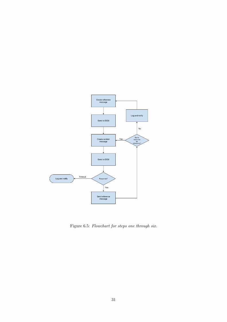
Figure 6.5: Flowchart for steps one through six.
31
Service Input size
DiagnosticSessionControl 1 byte
EcuReset 1 byte
ReadDataByIdentifier 2 bytes
ReadMemoryByAddress >3 bytes
SecurityAccess 4 byte
WriteDataByIdentifier 2 bytes
WriteMemoryByAddress >3 bytes
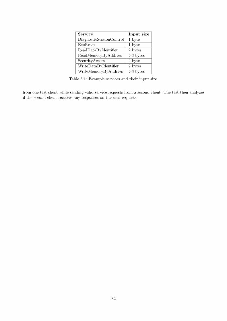
Table 6.1: Example services and their input size.
from one test client while sending valid service requests from a second client. The test then analyzesif the second client receives any responses on the sent requests.
32
7 Results and test evaluations
This section includes a presentation of the results from the tests described in Section 6. What thetest results can be used for as an adversary and possible countermeasures will be discussed in Section8. The results are evaluated for the two different test environments described in Section 6.
7.1 Information Disclosure / System Reconnaissance
7.1.1 System Scan
The scanning experiments were successful and found all enabled services and available DIDs as wellas their respective data lengths. On the evaluation board the results could be confirmed since it wasa white-box system. This gives confidence that the results from the production system also includedevery service present.
In the production system environment the scan resulted in an complete view of the DCM moduleconfiguration running. The scan was able to report all running services including the implementedsubfunctions and corresponding data identifiers. The scan discovered the specified input length of allreachable services. The scan reported that some subfuctions and data identifiers were placed behinda higher security level and were therefore not reachable at the default security level.
7.1.2 System Probing
The probing of the system was successful and was able to find the correct identification number ofthe DCM module in both of the test systems. The test also recorded the identification number of theresponse messages successfully in the systems.
7.1.3 Packet sniffing
Sniffing the CAN traffic allowed for the identification of the DCMs arbitration ID. Sniffing was doneon both a production system and an evaluation board.
In the production system the test resulted in a clear view of what nodes were communicating on theCAN bus. Identifying the arbitration ID of the DCM was only a matter of recognizing a frame as adiagnostics message. In this case a TesterPresent message was found, and the DCMs arbitration IDcould be identified by manually looking at the CAN traffic using the BusMaster logging software.
The evaluation board did not communicate externally, and therefore there were no packets to sniff.
7.1.4 Restricted Memory Address scan
This test could not be performed on the evaluation board due to that the ReadMemoryByAddress
service was not configured on the evaluation board.
In the production environment the test showed that it was possible to scan the memory that isreachable of the DCM module. It showed that it was possible to read all data in RAM but notpossible to write without having the right security access level.
33
7.1.5 Message handling rate
This test gave information about the rate at which the DCM module was able to handle requests. Onthe evaluation board the DCM module was able to respond and act on requests every 20 millisecondsand on the production system the DCM was able to handle requests every 10 milliseconds. The testalso discovered that if messages were sent to the evaluation board with no delay in between, thesystem crashed after a small amount of time and did not recover without a complete reset. Theproduction system was not negatively affected by the huge number of messages.
7.2 Tampering of ECU Software
7.2.1 Man In The Middle
The Man In The Middle test showed that it was possible to connect a malicious node inside thesystem and record the message received from the legitimate client and manipulate the payload beforeredirecting it to the DCM module without detection. The results was equal in both the evaluationenvironment and the production environment.
7.2.2 Brute force security access key
The test showed that the security access key could not be discovered by a brute force test within areasonable time if the key length is 4 bytes or longer. The test could only try two keys every seconddue to communication delays. And the brute force technique is only applicable if the access key staysthe same during the entire test. In the production system the test could not be applied due to thatthe security key algorithm was implemented in such a way that a new key was used after each reset.
7.2.3 Seed/Key sniffing
The sniffing test was done on an ECU ready for production. The test was able to pick up sevenseed/key pairs while sniffing the traffic of the system. It was also able to retrieve information aboutthe seed sized used in the system, in this system a seed size of 4 bytes was used. They were storedin a database before the test started to request seeds. Within just 5 minutes a match was found,allowing other scripts to write to any address in RAM.
There was no security access implementation ready on the evaluation board which made it impossibleto run the test on that specific system.
7.2.4 Seed Entropy
This test was only available to be performed in the production system environment. The SecurityAccessservice in the evaluation board was not configured to use a seed/key algorithm and we did not havethe knowledge to implement the service.
The result in the production system showed that it was possible to find a seed collision and to retrieveall possible seeds in 15 minutes. The test also resulted that it was possible to manually analyse thelist of seeds and find the seed generation algorithm.
34
7.2.5 Restricted Memory Address Write
This test showed that both evaluation environment and the production environment were able tovalidate the messages and therefore nullify the possibility to write to the restricted parts of thememory using the WriteMemoryByAddress service.
7.3 Denial of Service
7.3.1 Random Fuzzing
The Random fuzzing test is a tool to allow a security evaluator to test the robustness of the TOE. Inthe tests made the results differed depending on what system being tested.
Testing the evaluation board resulted in two major discoveries. The first was that when the systemreceived more than 30 000 messages the entire system crashed and stopped responding to requests,not only the DCM. The second discovery was that when the system received a valid service messagerequesting a reading of a DID longer than 16 bytes, the DCM stopped working. In neither of thecases the system recovered to a running state.
The test was conducted on the production system by sending over 3 million requests. The resultsshowed that the system was able to validate and discard the invalid requests out of all of the requestssent. The test showed that the system is not vulnerable to random messages that exceed boundariesand that it performs input validation.
The Random Fuzzing test showed that the configurations of both test environments give a highprotection against invalid request that is sent to the systems. The test also showed how importantmessage validation is, as could be seen in the first test when the evaluation system completely stoppedworking when a specific request was sent.
7.3.2 Intelligent Fuzzing
This test was preformed on both of the systems after running the System Scan test, where the servicesrunning on each of the systems was revealed. This information was then used as input for this test.In the evaluation board environment we also had knowledge about what services the DCM modulewas running, and could therefore verify the result.
When running the test on the evaluation board a limit had to be put in place so that the system wouldnot crash from receiving more than 30 000 messages, the limit found in the Random Fuzzing test. Thetest showed that the system could single out the invalid messages and exclude the processing of these re-quests. The test showed the same results as we could see in Random Fuzzing test, that the DCM modulestopped working when valid message was sent to service that requested a response longer than 16 bytes.
In the production system the intelligent fuzzing gave the same result as in Random Fuzzing test, thesystem was able to discard invalid or unexpected requests.
7.3.3 Flooding
The DCM was successfully flooded when sending messages at higher rates than it could handle(identified in the Message handling rate test). Legitimate traffic to the DCM was unable to getresponses from the DCM since it was busy handling the bogus traffic sent to flood it. Additionally,
35

the evaluation board crashed when receiving messages at a high rate and was unable to recover to aworking state.
36
8 Discussion and countermeasures
This section includes discussions and suggestions of countermeasures for each of the performed tests.The countermeasures discussed are meant to help securing a system running in a production systemenvironment. At the end of the chapter a general discussion is presented that covers the overallsecurity of the DCM module. It also includes a general way to counter the vulnerabilities of thesystem.
8.1 Information Disclosure / System Reconnaissance
8.1.1 System Scan
This test collects information about the target of evaluation and gets a view of the systems config-uration. The test can be compared to a server scan in the web domain where the goal is to findinformation of the running services and the server configurations. When a clear picture of the DCMmodule has been collected an adversary can start to look for vulnerabilities in a structured way.Many of the tests performed in this report build upon knowledge collected through this test. Thetest can also be a tool for developers to verify that the target system is configured according to thespecifications. It can also help security evaluation of the system by revealing if any old services thatwas used under development has been left in.
The System Scan test uses the ISO 14229-1 standard and that the DCM responds with specific errorresponses depending on how the services, sub-services and input lengths are configured.
The scan can be hard to counter, as explained in the previous section the communication can beencrypted and require authentication, but this can be computationally heavy and can be hard toimplement on all traffic and still cope with the real time demands of the system tasks. To cope withthis information leakage the developer can use this test and learn what the adversary might find outand prevent possible threats through that. This information leakage can be mitigated by havingthe DCM not responding unless the tester/client has been authenticated in some way. The systemwould then ignore to reply with the negative return codes found in ISO 14229-1 unless the clienthas been validated. The system could comply with the standard when the client has authenticated itself.
The test can easily be modified to scan other parts of the AUTOSAR system and not only the DCMmodule that was scanned in this thesis. In this way an even larger picture of the internal system canbe revealed.
8.1.2 System Probing
System probing is the first test used to gain information of a system when the adversary has minimalknowledge about the software architecture. By probing the system the adversary can not only findinformation about the ID of the DCM module, but could also be able to find other interesting IDnumbers. This test could also be used to find components that should not be present when the systemis deployed in production.
The difference between this test and the System Scan is that this test finds arbitration ID numbers(belonging to for example SW-Cs and specific ECUs), and the System Scan finds services available inthe DCM.
37
This test does however require some working knowledge about automotive systems, otherwise it wouldbe more like a fuzzing test only sending random messages.
8.1.3 Packet sniffing
The test gives a clear view of what an adversary can see and what information can be discovered fromonly listening to the communication. To an adversary with knowledge of the automotive systems thetest can supply information about what nodes are connected and how they are communicating on thenetwork. The test can very quickly discover the node IDs used.
Packet sniffing can also be very useful for an adversary due to the fact that the system communicationis in plain text and that the test can log secret seed/key communication. If the seed and the key canbe reused, the adversary can use the information to mount an impersonation attack.
To mitigate the possibility of packet sniffing a solution would be to encrypt all communication senton the network.
8.1.4 Restricted Memory Address scan
The memory address space of the DCM is laid out according to the locality principle, meaning that thememory used by the DCM is continuous in the RAM. With this test it is possible to find informationof accessible, writable, memory areas. If the test reveals that some memory addresses can be accessedwithout extra security privileges, the adversary can try to exploit this in different ways. An adversarycan use an accessible memory address to start a writing session and attempt to write over theallowed memory space and continue writing into restricted areas. The adversary could also exploit thepossibility that the open memory area could contain sensitive data that is used by services in the DCM.
This test can also be a tool for developers to test that the memory accessibility works as it is expectedbefore deploying the system.
8.1.5 Message handling rate
The message handling rate test gets information about at what rate requests can be managed. Thetest reveals information that can be used in further security tests, such as the flooding test or asystem stability test. The results from the two test environments show that the evaluation board wasconfigured to handle messages at a rate of one request every 20 milliseconds. The tested productionsystem was configured to handle a request every 10 milliseconds. The test also showed that theevaluation board crashed and did not recover when messages were sent without any delay and thatthe production system was able to handle it without crashing. The production system might have anupper limit unreachable by the test setup used in this project.
8.2 Tampering of ECU Software
8.2.1 Man In The Middle
This test reveals one of the most severe threats based on the result. Due to the problem of unau-thenticated plain text communication inside the vehicle an adversary could place itself on the busbetween a legitimate client and the targeted DCM module. The adversary can in this way decide whatinformation should be sent to and from the DCM. The adversary can thereby change or block requestsand responses that are being sent to and from the DCM. Due to the nature of the CAN bus, the
38
SecurityAccess service unlocks privileges for the entire bus and not only for the client that performsa valid authentication session, the adversary can take over the bus when the privileges are unlocked.This makes it possible for an adversary to connect to the CAN bus network, not only as a man inthe middle, and wait for the security authentication is performed before taking over the communication.
After the authentication is complete an adversary can record the data transferred during a repro-gramming session and replay the programming session in another vehicle and yield the same result.For example to unlock higher performance of the engine and only paying for one vehicle.
For an adversary with previous knowledge about ECU programming and the expertise to programtheir own software component, the system can be severely vulnerable to both security and safetythreats. An adversary able to add new software components could for example add a trojan thattriggers under specific conditions, such as a speed over 100 km/h and create a total block of the brakesystems.
This threat can be countered by always using an authentication scheme of the client that ensures thatthe client is authorized to perform the changes of the software. It can also be countered by usingencrypted communication while performing a reprogramming session.
8.2.2 Brute force security access key test
This test can be used to check that the system behaves in an expected way when an adversary tries toguess security access passwords. The test should not be applicable in real production systems wherethe security key should depend on a seed key response and not be hardcoded as in the evaluationboard setup used in this project.
A possible scenario could be:The standard states that a seed/key approach should be used to gain elevated privileges, it also statesthat a penalty time should be applied if a number of failed keys has been attempted [16]. The standarddoes not state how this should be implemented. This could potentially result in a insecure seed/keyimplementation that still is valid according to the standard. If the seed/key algorithm e.g. uses a hard-coded seed and key pair or a small sized key the implementation could potentially be insecure but valid.
Examples of insecure configurations, but valid according to the ISO standard, could be:
• Key length of less than 4 bytes. The ISO 14229-1 does not state a required length to beused for the security key. This open the possibility for a valid configuration using a very shortkey length. The test concluded that a key length over 4 bytes is desirable, resulting in a bruteforce time of over 50 years.
• Key hardcoded and less than 4 bytes. The standard states the Seed/key handshake asoptional. This open the configuration to be implemented using a fixed key that is used to unlockthe security access every time needed, resulting in a valid but insecure implementation.
• Number of failed key attempts before penalty back off time is too high, over 10tries. The standard does only state that there need to be a back off time penalty after anumber of failed attempts, but not the number of attempts. This open the configuration to beimplemented using a insecure large number of attempts before a penalty is applied, resulting ina very reduced time to brute force the key.
39
8.2.3 Seed/Key sniffing
This test is a sub-test to the packet sniffing test, but this test only targets the vital part of the securityaccess session data needed to unlock the security levels. The test looks for and stores the informationas soon as a login session is started by any legitimate client. This information can then be shared inan adversary community and might lead to a large database of seed/key pairs allowing adversaries toaccess the security levels or to reverse engineer the algorithm for computing the key.
8.2.4 Seed Entropy
Since the security access is built as a seed/key challenge response protocol, seed entropy is important.The security access key responses are limited to 5 tries before applying a penalty time of 10 secondsmaking a bruteforce attack on the key hard for an adversary. The seed request does not have apenalty rule similar to that of the key sending, but instead allows the adversary to request seeds at aspeed only limited by the message handling rate of the DCM. The advantage for an adversary is thatit can request seeds until one matches another previously recorded seed, and the key can be reused.This makes the the entropy of the seed very important. This test can be a good way to test the seedentropy of the system before deploying it.
As we could see from the result in Section 7.2.4 a seed collision was found within a few minutes andby recording the seeds it could quickly be determined that there was no randomness in the seedgeneration, making the entropy of the seed to small to be secure. In tested system we found that aseed size of 4 bytes was used. Implemented using a complete random seed algorithm this could be asecure entropy size but as it was configured the entropy became just a fraction of the possible entropyspace.
A recommendation for mitigating this vulnerability would be to require that the seed is generatedin a cryptographically secure way, and not through a counter or something of that sort. The statedsecurity implementations and restrictions for the key should also apply on the seed since they aredependent on each other.
8.2.5 Restricted Memory Address Write
This test concluded that in both of the test environments the systems were able to detect and protectagainst writing to the restricted areas.
This is a required security test to perform before any release of new DCM software. If the test wereto succeed, an adversary would be able to overwrite crucial memory areas that could lead to systemfailure. An adversary could possibly be able to upload a secondary boot loader including flash routinesto reprogram the full ECU software.
8.3 Denial of Service
8.3.1 Fuzzing based Security Tests
The fuzzing based tests only control the handling of malformed and invalid request messages and notthe rate at which the DCM handles requests.
40
Random Fuzzing
This test is constructed to reveal weaknesses in the systems input validation. The test is usefulfor validating the system before applying it in production. For an adversary the test can revealuntested input validation and invalidly formed requests that can result in safety and security risks ofthe vehicle. The test can be used to complement the intelligent fuzzing test due to that it createsmalformed requests that neither the developer nor the adversary would have thought of to test. Dueto the randomization and the lack of structure when creating requests the test can lead to very longexecution times before giving any results, if there are any. The test does not ensure that even knownvulnerabilities will be found and should be complemented with a more intelligent fuzzing method.
Due to that the test uses the valid communication path with the DCM the test can only be mitigatedby a well tested message validation, as the one implemented in both of the tested systems. To ensurethat the system has a correct boundary control and that the input validation works as expected atest like this should be applied in all steps of production, when each node DCM is configured andalso when a fully deployed system running multiple nodes is configured.
Intelligent Fuzzing
This test has the same capability as the dumb fuzzing test but with the advantage of being ableto aim the fuzzing towards known services in the system. Since there often are multiple devel-opers involved when implementing a system this can be a good way for each of the developersto test their service implementations individually before deploying it to be a part of the full sys-tem. For an adversary trying to perform this test the knowledge of how the system is configuredand what services are running is important. This information can be collected by the System Scan test.
To protect the system against an adversary able to run this test the same advice as in the RandomFuzzing test should be applied here.
8.3.2 Flooding
This test shows that it can be possible to deny communication with the DCM by sending a largenumber of requests. The test showed how vulnerable the systems are against blocking legitimateclients or other nodes from communicating with DCM modules. It also showed that it was possible toblock requests under selected times, such as software update sessions. This can potentially lead toboth safety and security problems.
If a reprogramming session were to take place and a flooding was being performed at the same time,the reprogramming frames would be blocked out. The scenario of a lost reprogramming session is notaddressed in ISO 14229-1, and since the DCM is configured to suppress positive responses a techniciancan believe that a software component has been updated even if the reprogramming was not actuallyperformed. If the reprogramming was a security patch, the system would still be vulnerable andcould be exploited by an adversary. If flooding can be performed while the vehicle is in motion andthe flooding can result in that a crucial ECUReset request to the DCM was dropped, the safety ofpassengers or people close to the vehicle can be affected. According to our contacts in the industry,there are cases where such ECUReset messages are sent while the vehicle is in motion to force anECU into a safe state. If this message was denied the ECU in question could be stuck in a non-safe state.
The flooding problem is hard to mitigate due to the CAN communication structure. The messagestructure does not include source information that can be used to exclude a node that sends an unusualamount of requests. In the case where a communication protocol has source information included, as
41
in the 29 bit extended mode of CAN [32], the attack can be mitigated by using an excluding policy. Ifthe adversary could be able to change the source identification in the messages the attack would stillbe possible and an authentication policy would be preferred instead. To protect against flooding whencommunication without identification is used, that is the most common communication protocol invehicles and also in our setup, the separation of critical nodes can be used, where the critical nodes areplaced in separate sub-networks. This would make sure that the more easily accessible ECUs for anattacker, i.e. infotainment and the like, would not be able to deny communication in the more criticalnetwork where for example engine control would reside. The use of a low speed communication buswhere nodes are not able to send messages faster than the DCM module can handle can be one wayof mitigating the problem. A token based communication protocol can be used where all the involvedcommunicating nodes have their allotted time slot where they are able to send message on the bus.
8.4 ISO 14229
ISO 14229-1 defines how the information flow of the DCM services should be done. The flow toperform a service execution is divided into three parts, the standardized steps, optional/recommendedsteps and the vehicle manufacturer steps. The standardized steps are the only mandatory stepsneeded to comply with the standard. Following the standardized steps, the programming of an ECUwill be performed through an insecure session without any authentication or integrity.
If the Optional/recommended step were instead included in the standardized flow, the services wouldbe implemented more securely.
8.5 Overall Discussion
The tests presented in this report shows that it was possible to find security weaknesses of anAUTOSAR DCM module. It also shows that even if the security rules of ISO 14229-1 are implementedin the system it can still be vulnerable to attacks.
Our tests can be expanded to include more tests that explore more and other attack surfaces of theDCM module. The number of security tests in this report was limited due to the time limit of theproject and the ability to configure the evaluation system to include more services. We decided toinclude these tests due to that they all together are in the scope of the possible threats presented inthe threat model.
The tests done in this report was limited to the scope of just embracing the DCM module but couldbe adapted to test a more complete set and other modules of the AUTOSAR implementation.
When doing a threat model of a system it is important to have both security experts and experts inthe area in which the system operates present. Otherwise the threat model and risk assessment maybe skewed to be either to lenient or to strict. Having developers with an education in security shouldalso be preferred since they have knowledge of the most frequent pitfalls.
Today most developers in the automotive industry are encouraged to follow the MISRA-C standard[7], which has a goal to ”promote best practice in developing safety related electronic systems in roadvehicles and other embedded systems”. Another set of coding guidelines targeting security insteadof safety is the CERT secure coding guidelines. It’s a community driven effort to provide rules andrecommendations to ”eliminate insecure coding practices and undefined behaviours that can lead to
42
exploitable vulnerabilities”.
As presented by Vembar and Holle [40] 43% of the security recommendations in CERT are not coveredin MISRA, 37% of the guidelines are covered, and 1% of the guidelines in CERT are contradicted byMISRA. The rest of the CERT guidelines are only partially covered by MISRA.
Developers of automotive embedded systems must have guidelines not only for safety, but for securityas well, since vulnerabilities in security will affect safety.
Quantitative security such as threat modeling and risk assessment are very subjective processes. Twoteams assessing the risks of one system may very well come up with different assessments. A researchpaper by Verendel [41] concludes that there’s a lack of validation of quantitative methods regardingsecurity. It does not, however, rule out quantitative processes as inherently lacking, but states thatmore empirical validation of such processes would be beneficial.
43
9 Conclusions
This report has shown that it is possible to gain unauthorized access to vital parts of the vehicle’sembedded system by using common attacks and vulnerabilities found in the computer security domain.We have shown that some implementations of the AUTOSAR diagnostic basic software module maybe susceptible to denial of service attacks even by adversaries that are new to the automotive setting,even when the implementations were following the ISO standard. We also discuss the potential riskthat the security vulnerabilities can lead to and how they can endanger safety of the vehicle’s passengers.
A number of the vulnerabilities found in the diagnostic communication manager in this thesis can alsobe found in the OWASP Top 10 web security risks from 2013 [28]. OWASP (Open Web ApplicationSecurity Project) is an international organization aiming to enable other organizations develop andmaintain web applications that can be trusted, through rigorous security.
The threats from OWASPs Top 10 list that has been identified in our tests are:
• Broken Authentication and Session Management
• Sensitive Data Exposure
The broken authentication management vulnerability was identified in the Seed/Key sniffing test (seeSection 7.2.3). OWASP describes this vulnerability as: ”Credentials can be guessed or overwrittenthrough weak account management functions”. In this case the Seed/Key algorithm could be guessedquite easily, which is a direct mapping from the OWASP vulnerability description.
A sensitive data exposure vulnerability was found through the packet sniffing test (see Section7.1.3). This vulnerability is described as: ”Is any of this data transmitted in clear text, internally orexternally?”. In the setting for this thesis all data is transmitted in clear text, this vulnerability isclearly present in the system.
We present different possible attack scenarios and show how the tested systems responded to thedifferent scenarios. We also give examples on how the security vulnerabilities can be mitigated.
By creating attack trees for the three threats identified (see Section 6.2) we have designed a numberof tests that should be done during the development phase of the diagnostic system. The threatscould all be mitigated through the use of encrypted communication and an authentication scheme forthe communication channels. As presented by Kleberger and Olovsson, an IPSec implementationcould counter these security threats if ethernet is used together with the IP stack to communicatebetween the nodes inside the future vehicles.
Van Herrewege et al. presents an authentication scheme specifically for CAN they call CANAuth[39]. The authentication scheme is backwards compatible and can be run on any CAN bus withoutmodifying existing nodes. However, it does not enable encryption of the communication, and is notprotected against denial of service attacks.
9.1 Future work
This report shows that it is possible to endanger the safety of a vehicle if it is possible to gain accessto its internal communication network. With this knowledge, future work can be done on investigatethe possibility of employing the same security tests from a remote system gaining access via any
44

wireless interface, such as Bluetooth, RFID or WLAN.We have focused on tests on the internal communcation, but one could imagine tests done more onhardware, for example analysing a binary file extracted from JTAG.It could also be an interesting project to implement some security mechanisms that counter thethreats and vulnerabilities found in this thesis. For example a project could be to implement somecryptographic authentication scheme similar to IPSec for the CAN bus.
45
References
[1] ArcCore. Arctic Studio. Feb. 2015. url: http://www.arccore.com/products/arctic-
studio/.[2] ArcCore. ArcticCore v.7.0.0. May 2015. url: http://www.arccore.com/products/arctic-
core/arctic-core-for-autosar-4-x/.[3] ArcCore. VK-EVB-M3 Evaluation board. May 2015. url: http://www.arccore.com/products/
vk-evb/vk-evb-m3/.[4] S. Bayer et al. Automotive Security Testing - The Digital Crash Test.[5] BUSMASTER homepage. Feb. 2015. url: http://rbei-etas.github.io/busmaster/.[6] CAN-Case homepage. Feb. 2015. url: http://vector.com/vi_cancase_xl_log_en.html.[7] M. Consortium. MISRA homepage. May 2015. url: http://www.misra-c.com/.[8] C. K. Deepika, G. Bjyu, and V. S. Vishnu. Implementation of DCM module for AUTOSAR
Version 4.0 (2013).[9] Hackers Reveal Nasty New Car Attacks–With Me Behind The Wheel. July 2013. url: http:
//www.forbes.com/sites/andygreenberg/2013/07/24/hackers-reveal-nasty-new-car-
attacks-with-me-behind-the-wheel-video/.[10] F. Holik et al. “Effective penetration testing with Metasploit framework and methodologies”.
Nov. 2014.[11] M. S. Idrees et al. “Secure automotive on-board protocols: a case of over-the-air firmware
updates”. Communication Technologies for Vehicles. Springer, 2011, pp. 224–238.[12] IHS Global Insight, Inc. Resistance is Futile - Electronics are on the rise: Electronic Control
units and ommunication protocols (2009).[13] International Organization for Standardization homepage. Feb. 2015. url: http://www.iso.org.[14] M. Islam. HEAVENS Project Terminologies. Jan. 2015.[15] ISO 11898-1. 2003.[16] ISO 14229-1. 2013.[17] ISO 15765-2. 2011.[18] M. Jensen, N. Gruschka, and N. Luttenberger. The Impact of Flooding Attacks on Network-based
Services (2008).[19] P. Kleberger and T. Olovsson. Securing Vehicle Diagnostics in Repair Shops (2014).[20] K. Koscher et al. “Experimental security analysis of a modern automobile”. In Proceedings of
IEEE Symposium on Security and Privacy in. 2010.[21] A. Lautenbach and M. Islam. HEAVENS Deliverable D2 - Security models, ver. 1.0. Dec. 2014.[22] B. M. Luettmann and A. C. Bender. Man-in-the-middle attacks on auto-updating software
(2007).[23] Microsoft. “Simplified implementation of the Microsoft SDL”. Nov. 2010.[24] E. K. Mohd and F. Khan. A Comparative Study of White Box, Black Box and Grey Box Testing
Techniques (2012).[25] S. Myagmar, A. J. Lee, and W. Yurcik. “Threat modeling as a basis for security requirements”.
Symposium on requirements engineering for information security (SREIS). Vol. 2005. 2005,pp. 1–8.
[26] Nmap. url: http://nmap.org.[27] OpenVAS homepage. Feb. 2015. url: http://openvas.com/about.html.[28] OWASP. OWASP Top Ten Project 2013. May 2015. url: https://www.owasp.org/index.
php/Top10#OWASP_Top_10_for_2013.[29] PEAK-CAN homepage. Feb. 2015. url: http://www.peak-system.com/.[30] E. Project. E-safety Vehicle Intrusion Protected Applications (EVITA). url: http://www.evita-
project.org/.
46
[31] H. Project. HEAling Vulnerabilities to ENhance Software Security and Safety. url: http:
//www.sp.se/en/index/research/dependable_systems/heavens/Sidor/default.aspx.[32] H.-C. Reuss. Extended Frame Format - A New Option of the CAN protocol. May 1993.[33] A. Ruddle et al. EVITA Deliverable D2.3: Security requirements for automotive on-board
networks based on dark-side scenarios. Dec. 2009.[34] B. Schneier. Attack trees. Dr. Dobb’s Journal 24 (12 Dec. 2009), 21–29.[35] B. Schneier and J. Wiley. Secrets and Lies: Digital Security in a Network World (2000).[36] A. Shostack. Threat Modeling: Designing for Security. John Wiley & Sons, Inc., 2014, pp. 209–
213. isbn: 978-1-118-80999-0.[37] F. Swiderski and W. Snyder. Threat modeling. Microsoft Press, 2004.[38] A. Takanen. Fuzzing for the Masses. Network Security 2008.8 (Aug. 2008), 4–6.[39] A. Van Herrewege, D. Singelee, and I. Verbauwhede. “CANAuth-a simple, backward com-
patible broadcast authentication protocol for CAN bus”. ECRYPT Workshop on LightweightCryptography 2011. 2011.
[40] P. Vembar and J. Holle. Secure Coding and MISRA C in ECU Development. ESCAR, Hamburg.Nov. 2014.
[41] V. Verendel. “Quantified security is a weak hypothesis: a critical survey of results and assump-tions”. Proceedings of the 2009 workshop on New security paradigms workshop. ACM. 2009,pp. 37–50.
[42] P. Vyleta. “Automated penetration testing in automotive industry”. MA thesis. Czech TechnicalUniversity in Prague, 2014.
[43] G. Weidman. Penetration testing: a hands-on introduction to hacking. English. San Francisco,CA: No Starch Press, 2014. isbn: 9781593275648; 1593275641. url: www.summon.com.
[44] winIDEA open homepage. Feb. 2015. url: http://www.isystem.com/download/winideaopen.[45] M. Wolf, A. Weimerskirch, and C. Paar. “Security in automotive bus systems”. in: Proceedings
of the Workshop on Embedded Security in Cars (escar)’04. 2004.
47