Embed Size (px)
Citation preview

8/13/2019 Testing & Adjusting Your MVP Pumping System
http://slidepdf.com/reader/full/testing-adjusting-your-mvp-pumping-system 1/47
Rev. 01/2013
TESTING & ADJUSTING
YOUR MVP PUMPINGSYSTEM

8/13/2019 Testing & Adjusting Your MVP Pumping System
http://slidepdf.com/reader/full/testing-adjusting-your-mvp-pumping-system 2/47
Testing & Adjusting Manual
Rev. 01/2013 Page | 2
CORPORATE HEADQUARTERS and MANUFACTURING11692 56
th Court * Clearwater, FL 33760 * Tel 727-573-2955 * Fax 727-571-3636
TECHNOLOGY CENTER and MANUFACTURING1862 Ives Ave. * Kent, WA 98032 * Tel 253-854-2660 * Fax 253-854-1666
MVP Plastech UKChilsworthy Beam, Gunnislake, Cornwall, PL18 9AT UK, * Tel: +44 (0) 1822 832621
Fax: +44 (0) 1822 833999
www.mvpind.com
8/13/2019 Testing & Adjusting Your MVP Pumping System
http://slidepdf.com/reader/full/testing-adjusting-your-mvp-pumping-system 3/47
Testing & Adjusting Manual
Rev. 01/2013 Page | 3
Table of Contents
SECTION: Page
TERMS & CONDITIONS OF SALE 4
SAFETY & WARNINGS 7
INTRODUCTION 16
ESTABLISHING A SPRAY FAN 19
SPRAY TESTING 22
POUR TESTING 31
CHARGEABLE ACCUMULATORS 34
INTERNAL START-UP & SHUT-DOWN 38
APPENDIX 43
REVISION INFORMATION 45
8/13/2019 Testing & Adjusting Your MVP Pumping System
http://slidepdf.com/reader/full/testing-adjusting-your-mvp-pumping-system 4/47
Testing & Adjusting Manual
Rev. 01/2013 Page | 4
Terms & Conditions of Sale: 1. ACCEPTANCE: Acceptance of any purchase order from a customer or potential customer (“Buyer”) is subject to credit approval byGSSC, Inc. (“Seller”), acceptance of the purchase order by Seller and, when applicable, any manufacturer, vendor, or other third party thatprovides goods to Seller for resale to Buyer (“Vendor”). If Seller, in its sole discretion, determines that Buyer's credit becomes unsatisfactory
or it has reasonable grounds for insecurity, Seller reserves the right, upon notice to Buyer, to demand adequate assurance of dueperformance from Buyer and/or terminate any purchase order with no liability to Seller. BY REQUESTING A QUOTE FROM SELLER, ACCEPTING AN INVOICE FROM SELLER, OR PRESENTING A PURCHASE ORDER TO SELLER, BUYER CONFIRMS THAT THESETERMS & CONDITIONS SHALL GOVERN ALL PURCHASES OF PRODUCTS OR MATERIALS PROVIDED TO BUYER BY SELLER(“GOODS”). GOODS SOLD BY SELLER ARE EXPRESSLY SUBJECT TO THE TERMS AND CONDITIONS SET FORTH HEREIN AND ANY DIFFERENT OR ADDITIONAL TERMS OR CONDITIONS SET FORTH IN A PURCHASE ORDER OR SIMILARCOMMUNICATION RECEIVED FROM BUYER ARE OBJECTED TO A ND SHALL NOT BE BINDING UPON SELLERUNLESS SPECIFICALLY AGREED TO IN WRITING BY AN AUTHORIZED CORPORATE OFFICER OF SELLER.NO SELLEREMPLOYEE OR AGENT HAS THE AUTHORITY TO MODIFY THESE TERMS & CONDITIONS VERBALLY. SELLER OBJECTS TO ANDREJECTS ANY TERMS BETWEEN BUYER AND ANY OTHER PARTY, AND NO SUCH TERMS, INCLUDING BUT NOT LIMITED TO ANYGOVERNMENT REGULATIONS OR “FLOWDOWN” TERMS, SHALL BE A PART OF OR INCORPORATED INTO ANY PURCHASE ORDERFROM BUYER TO SELLER, UNLESS AGREED TO IN WRITING BY AN AUTHORIZED REPRESENTATIVE OF SELLER.2. PRICES AND TAXES: Buyer agrees to pay the prices quoted by Seller or listed on any related invoice, and is responsible for additionalapplicable shipping and handling charges, taxes, duties, and charges for import and export licenses and certificates. All prices quoted bySeller are subject to change without notice. Seller will generally collect applicable taxes along with the purchase price unless Buyer submitsa valid tax exemption certificate, and indicates which Goods are covered by it. Prices on special-order Goods may be subject to changebefore shipment. In order to be corrected any discrepancies in pricing and/or quantities on invoices must be reported by Buyer within thirty(30) days of the invoice date.3. PAYMENT: Payment terms are 30 days net from the invoice date or upon such other terms approved by Seller in writing. Retainage shall notapply, and Buyer shall not hold back any retainage from Seller, even if retainage is part of any contract between Buyer and any other party.Payment is not contingent on Buyer’s ability to collect or obtain funds from any other party. Credit card sales are billed at the time of purchase.Buyer expressly represents it is solvent at the time it places any purchase order with Seller. Seller, in its sole discretion, may determine that Buyer’sfinancial condition requires full or partial payment prior to manufacture or shipment. If Buyer fails to make any payment when due, Seller reservesthe right to suspend performance. Buyer agrees to pay a charge on all amounts past due at the rate of 1 ½% per month (18% per year) or themaximum lawful rate, whichever is less. In the event of non-payment, Buyer agrees to pay Seller’s reasonable attorney fees and court costs, if any,incurred by Seller to collect payment, and all applicable interest charges. Seller may apply payments to any outstanding invoices unlessBuyer provides specific payment direction. 4. TITLE AND RISK OF LOSS OR DAMAGE: As to Goods delivered directly by Seller, title passes upon delivery at the place Buyerreceives possession; and, thereafter, all risk of loss or damage shall be on Buyer. All other sales are F.O.B., point of shipment, and Buyertakes title and assumes responsibility for risk of loss or damage at the point of shipment for such sales. Claims for Goods damaged in transitare Buyer’s sole responsibility when not delivered directly by Seller.5. QUOTATIONS: All quotations expire thirty (30) days from the date of the quotation unless otherwise noted on the quotation. This timelimit applies even if Buyer uses the quotation to submit a job or project bid to any other party.
6. ASSIGNMENT: The Buyer’s rights and responsibilities under any purchase order or these Terms & Conditions shall not be assigned byBuyer without the express written consent of the Seller.7. RETURN OF GOODS: Permission to return items must be requested and granted in advance. No credit will be given if items arereturned prior to requesting and receiving permission. Subject to the foregoing, Seller shall accept returns of Goods for any reason for aperiod of thirty (30) days following shipment for exchange or refund of the purchase price; provided, that such Goods must be unused and aresubject to a 15% restocking charge, which may be increased or decreased, in the Seller’s sole discretion, depending on the reason for such return. Any Goods which were special ordered by Buyer are may not be returned, and any such Goods which are returned are subject to arestocking/cancellation fee of 100% of the cost of the Goods. Goods shall be deemed accepted by Buyer (and cannot thereafter bereturned), if Buyer fails to object to the Goods within thirty (30) days after the Goods are received by Buyer.8. CANCELLATION: The Buyer may cancel any purchase order prior to shipment of the Goods by mutual agreement of the partiesand upon payment to Seller of reasonable and proper cancellation charges.9. TERMINATION: Seller may terminate the whole or any part of any purchase order if there is a material breach of these Terms & Conditions. Inthe event of any such breach, the Seller will provide Buyer with written notice of the nature of the breach and the Seller’s intention to terminate fordefault. In the event Buyer does not cure such failure within ten (10) days of such notice, Seller may, by written notice, terminate the purchaseorder; provided, that Buyer shall continue its performance to the extent not terminated.10. CHANGE IN BUYER’S FINANCIAL CONDITION: Seller reserves the right to cancel any order or to require full or partialpayment in advance without liability to Seller in the event of: (i) insolvency of the Buyer; (ii) the filing of voluntary petition in
bankruptcy by Buyer; (iii) the appointment of a Receiver or Trustee for the Buyer; (iv) the execution by Buyer of an assignment forbenefit of creditors; or (v) past due payment on previous shipments to Buyer by Seller. Seller reserves the right to cancel Buyerscredit at any time for any reason.11. INTERPRETATION RESPONSIBILITY; PRODUCT USE AND SAFETY: Seller does not guarantee that the Goods it sells conform toany plans and specifications or intended use. When plans and specifications are involved, Buyer is solely responsible for verifying Seller’sinterpretations of such plans and specifications, and it is Buyer’s sole responsibility to assure that Seller’s Goods will be acceptable for anyspecific job. When Seller offers substitute Goods on any proposal, Buyer is solely responsible for confirming their acceptability.12. DELIVERY: Shipping dates given in advance of actual shipment are approximate and not guaranteed. All contract dates and timelinesbegin upon receipt by Seller of a purchase order, Buyer’s acceptance of these Terms & Conditions, and the payment of any required downpayment.
8/13/2019 Testing & Adjusting Your MVP Pumping System
http://slidepdf.com/reader/full/testing-adjusting-your-mvp-pumping-system 5/47
Testing & Adjusting Manual
Rev. 01/2013 Page | 5
13. EXCUSABLE DELAYS: Seller shall have no liability if its performance is delayed or prevented by causes beyond its reasonable control,including, without limitation, acts of nature, labor disputes, government priorities, transportation delays, insolvency or other inability toperform by any Vendor, or any other commercial impracticability. In the event of any such delay, the date of delivery or performance shallbe extended for a period equal to the time lost by reason of delay. If Goods are held or stored beyond the delivery date for the convenienceof Buyer, such Goods shall be so stored at the risk and expense of Buyer.14. CLAIMS: Claims for any nonconforming Goods must be made by Buyer, in writing, within ten (10) days of Buyer’s receipt of such Goodsand must state with particularity all material facts concerning the claim then known to Buyer. Failure by Buyer to give notice within such ten(10) day period shall constitute an unqualified acceptance of such Goods by Buyer, and a waiver of any right to reject or revoke acceptance
of such Goods.15. WARRANTIES:(a) SELLER’S WARRANTIES: Seller warrants that all Goods sold shall mechanically operate as specified and shall be free from faults inrespect to materials and workmanship for a period of: (i) for parts, twelve (12) months from the date of invoice, and (ii) for systems, twelve(12) months from start-up, or, if earlier, eighteen (18) months from the date of the bill of lading. Seller also warrants that the Goods shall,upon payment in full by Buyer for the Goods, be free and clear of any security interests or liens. Buyer’s exclusive remedy for breach of suchwarranties shall be limited to repair or replacement costs or termination of any security interests or liens, and Seller shall have noresponsibility for reimbursing repair costs incurred by Byer in connection with Goods without first giving written authorization for suchcharges. In any claims by the Buyer against the Seller in respect of the Goods, the liability of the Seller shall be limited to the value of theGoods. This warranty applies only to Goods properly used and maintained and does not apply to any Goods which are misused,neglect or accident, or which has been installed, operated, repaired, altered or modified other than in accordance with instructions orwritten authorization by Seller. This warranty does not apply to any Goods not manufactured by Seller, and Buyer's sole warrantywith respect to such Goods shall be that of the Seller’s Vendor, if any.(b) VENDOR’S WARRANTIES: Seller shall assign to Buyer any Vendor warranties and/or remedies provided to Seller by its Vendor.(c) INTELLECTUAL PROPERTY INFRINGEMENT: SELLER DISCLAIMS ANY AND ALL WARRANTIES AND/OR INDEMNIFICATIONS AGAINST INFRINGEMENT OF ANY INTELLECTUAL PROPERTY RIGHTS OF ANY NATURE. SELLER SHALL, IF GIVEN PROMPTNOTICE BY BUYER OF ANY CLAIM OF INTELLECTUAL PROPERTY INFRINGEMENT WITH RESPECT TO ANY GOODS SOLD
HEREUNDER, REQUEST THE APPLICABLE VENDOR TO GRANT FOR THE BUYER SUCH WARRANTY OR INDEMNITY RIGHTS ASSUCH VENDOR MAY CUSTOMARILY GIVE WITH RESPECT TO SUCH GOODS.(d) LIMITATIONS: THERE ARE NO OTHER WARRANTIES WRITTEN OR ORAL, EXPRESS, IMPLIED OR BY STATUTE. SELLERSPECIFICALLY DISCLAIMS ALL IMPLIED WARRANTIES OF MERCHANTABILITY OR FITNESS FOR A PARTICULAR PURPOSE. NOREPAIR OF GOODS OR OTHER COSTS ARE ASSUMED BY SELLER UNLESS AGREED TO, IN ADVANCE, IN WRITING.16. LIMITATIONS OF LIABILITY: UNLESS APPLICABLE LAW OTHERWISE REQUIRES, SELLER’S AND ANY VENDOR’S TOTALLIABILITY TO BUYER, BUYER’S CUSTOMERS OR TO ANY OTHER PERSON, RELATING TO ANY PURCHASES GOVERNED BYTHESE TERMS & CONDITIONS, FROM THE USE OF THE GOODS FURNISHED OR FROM ANY ADVICE, INFORMATION OR ASSISTANCE PROVIDED BY SELLER (BY ANY METHOD, INCLUDING A WEB SITE), IS LIMITED TO THE PRICE OF THE GOODSGIVING RISE TO THE CLAIM. NEITHER SELLER NOR ITS VENDORS SHALL BE LIABLE FOR ANY SPECIAL, INCIDENTAL, DIRECT,CONSEQUENTIAL OR PENAL DAMAGES, INCLUDING, BUT NOT LIMITED TO BACKCHARGES, LABOR COSTS, COSTS OFREMOVAL, REPLACEMENT, TESTING OR INSTALLATION, LOSS OF EFFICIENCY, LOSS OF PROFITS OR REVENUES, LOSS OF USEOF THE GOODS OR ANY ASSOCIATED GOODS, DAMAGE TO ASSOCIATED GOODS, LATENESS OR DELAYS IN DELIVERY,UNAVAILABILITY OF GOODS, COST OF CAPITAL, COST OF SUBSTITUTE GOODS, FACILITIES OR SERVICES, DOWNTIME, ORCLAIMS FROM BUYER’S CUSTOMERS OR OTHER PARTIES. IF SELLER FURNISHES BUYER WITH ADVICE OR OTHER ASSISTANCE WHICH CONCERNS ANY GOODS SUPPLIED HEREUNDER, OR ANY SYSTEM OR EQUIPMENT IN WHICH ANY SUCHGOODS MAY BE INSTALLED, AND WHICH IS NOT REQUIRED PURSUANT TO THESE TERMS & CONDITIONS, THE FURNISHING OFSUCH ADVICE OR ASSISTANCE WILL NOT SUBJECT SELLER TO ANY LIABILITY, WHETHER BASED ON CONTRACT, WARRANTY,TORT (INCLUDING NEGLIGENCE) OR OTHER GROUNDS.17. BUYER’S USE OF GOODS: Many factors beyond Seller’s control contribute to the success of the Buyer’s finished products, such as rawmaterials used to manufacture the products. Seller is not liability for the quality or quantity of finished products produced by Buyer with the use ofthe Goods.18. EXPORTS: If Goods are sold for export, Seller’s standard terms & condition for export sales, if any, shall also apply. Acceptance of exportorders is not valid unless confirmed in writing by Seller. Buyer, and not Seller, is responsible for compliance with all United States export controlrules and regulations. Buyer shall not name Seller as shipper or exporter of record in connection with the export of any Goods purchased fromSeller.19. INSTALLATION: Installation of the Goods is the responsibility of Buyer, unless otherwise indicated in the quotation or invoice provided toBuyer. Notwithstanding the foregoing, however, Seller will provide installation supervision personnel within thirty (30) days of Buyer’s request. Ifan installation for which the Seller is to participate is delayed by the Buyer more than six (6) months after the date of shipment of the Goods, or ifBuyer’s facility, materials, or parts are not prepared for installation for such period of time, Seller shall be entitled to invoice the Buyer for theanticipated installation costs, up to $1,250 per day plus expenses, for each of Seller’s installations technicians which are on site.20. ANTI-MONEY LAUNDERING RESTRICTIONS: Seller rejects questionable purchase orders and payments: Except for pre-approvedcredit arrangements, Seller rejects third-party payments, cashiers' checks, money orders and bank drafts. Seller accepts only checks
imprinted with Buyer’s name; wire transfers originated in Buyer's account; letters of credit with Buyer as account party; and credit or debitcards in Buyer’s name. All payments must be by single instrument in the amount of the invoice, less credits, from banks acceptable toSeller.21. GOVERNING LAW: These Terms & Conditions and all disputes related to it shall be governed by the laws of the State of Florida, UnitedStates of America, without giving effect to its conflict of law rules.
8/13/2019 Testing & Adjusting Your MVP Pumping System
http://slidepdf.com/reader/full/testing-adjusting-your-mvp-pumping-system 6/47
Testing & Adjusting Manual
Rev. 01/2013 Page | 6
22. JURISDICTION AND VENUE: The parties hereby irrevocably submit to the jurisdiction of the state courts of the State of Floridaand to the jurisdiction of the United States District Court for the Middle District of Florida, for the purpose of any suit, action, or otherproceeding related to, arising out of or based upon these Terms & Conditions or in any way related to, arising out of or involving saleof Goods hereunder; waive and agree not to assert by way of motion, as a defense, or otherwise, in any such suit, action, orproceeding, any claim that it is not subject personally to the jurisdiction of the above-named courts, that its property is exempt orimmune from attachment or execution, that the suit, action, or proceeding is brought in any inconvenient forum, that the venue of thesuit, action, or proceeding is improper, or that these Terms & Conditions or the subject matter hereof may not be enforced in or bysuch court; and waive and agree not to seek any review by any court of any other jurisdiction which may be called upon to grant an
enforcement of the judgment of any such Florida state or federal court. The parties hereby consent to service of process byregistered mail at the address to which notice is to be given. The exclusive venue for any proceeding under these Terms &Conditions shall be solely in any state court in Pinellas County, Florida, or the Federal District Court for the Middle District of Florida,Tampa Division, sitting in Tampa, Florida. Buyer acknowledges that the prices for Goods offered hereunder are in part dependenton Buyer’s consent to jurisdiction in Florida and exclusive venue in Pinellas County, Florida or the Federal District Court for theMiddle District of Florida, Tampa Division, sitting in Tampa, Florida, and without Buyer’s consent to this jurisdiction and venueprovision the prices for the Goods may be higher.23. GENERAL: Any representation, affirmation of fact and course of dealing, promise or condition in connection therewith or usageof trade not contained herein, shall not be binding on either party. If any provision hereof shall be unenforceable, invalid or void forany reason, such provision shall be automatically voided and shall not be part of these Terms & Conditions and the enforceability orvalidity of the remaining provisions of these Terms & Conditions shall not be affected thereby.TO THE EXTENT NOT CONTRARY TO APPLICABLE LAW, THE FOLLOWING SHALL APPLY:24. Buyer waives any available homestead exemption as well as any and all requirements or rights with regard to notice, demand,presentment, or protest and appoint any employee or attorney of Seller to appear in any court of competent jurisdiction for thepurpose of confessing judgment for all amounts due Seller pursuant to these terms and conditions.25. Buyer hereby waives all rights to notice, judicial hearing or prior court order in connection with Seller’s obtaining any prejudgmentremedy in connection with said transactions or extensions of same. Buyer also waives any and all objection which Buyer might
otherwise be able to assert now or in the future to the exercise or use by Seller of any right of setoff, repossession or self-help asmay presently exist under statute, including the Uniform Commercial Code and common law.IMPORTANT NOTICE: THIS INSTRUMENT PERMITS SELLER TO OBTAIN AND USE YOUR INDIVIDUAL CREDIT HISTORY FOR
CREDIT EVALUATION PURPOSES. THIS INSTRUMENT FURTHER CONTAINS A CONFESSION OF JUDGMENT PROVISION AND
OTHER WAIVERS, WHICH CONSTITUTES A WAIVER OF IMPORTANT RIGHTS YOU MAY HAVE, AND IF YOU DO NOT PAY ON TIME,
ALLOWS SELLER TO OBTAIN A JUDGMENT AGAINST YOU WITHOUT FURTHER NOTICE OR YOUR PRIOR KNOWLEDGE. BY
ACCEPTING THESE TERMS YOU GIVE UP YOUR RIGHT TO NOTICE AND TRIAL. THE POWERS OF THE COURT CAN BE USED TO
COLLECT THE AMOUNT DUE REGARDLESS OF ANY CLAIMS YOU MAY HAVE WHETHER FOR RETURNED OR FAULTY GOODS,
FAILURE BY SELLER TO COMPLY WITH THESE TERMS & CONDITIONS, OR ANY OTHER CAUSE.
8/13/2019 Testing & Adjusting Your MVP Pumping System
http://slidepdf.com/reader/full/testing-adjusting-your-mvp-pumping-system 7/47
Testing & Adjusting Manual
Rev. 01/2013 Page | 7
SAFETY & WARNING INFORMATION
OPERATING YOUR POLYESTER SYSTEM SAFELY
1. Introduction
Any tool, if used improperly, can be dangerous. Safety is ultimately the responsibility of thoseusing the tool. In like manner, safe operation of polyester processes is the responsibility of thosewho use such processes and those who operate the equipment. This manual outlinesprocedures to be followed in conducting polyester operations safety. This system has beenspecifically designed for use of Polyester Resin, Gel-Coat, and Methyl Ethyl Ketone Peroxides(MEKP) applications. Other formulations or blends considered for use in this equipment isstrictly prohibited without the expressed consent by Magnum Venus Plastech Inc. MagnumVenus Plastech cannot eliminate every danger nor foresee every circumstance that might causean injury during equipment operation. Some risks, such as the high pressure liquid stream thatexits the spray tip, are inherent to the nature of the machine operation and are necessary to theprocess in order to manufacture the end-product. For this reason, ALL personnel involved inpolyester operations should read and understand the Safety Manual. It is very important for thesafety of employees involved in the operation that equipment operators, maintenance andsupervisory personnel understand the requirements for safe operation. Each user shouldexamine his own operation, develop his own safety program and be assured that his equipmentoperators follow correct procedures. Magnum Venus Plastech hopes that this manual is helpfulto the user and recommends that the precautions in this manual be included in any suchprogram. Magnum Venus Plastech recommends this Safety Manual remain on your equipmentat all times for your personnel safety. In addition to the manual, Magnum Venus Plastechrecommends that the user consult the regulations established under the Occupational Safety &Health Act (OSHA), particularly the following sections:
1910.94 Pertaining to Ventilation.
1910.106 Pertaining to flammable liquids
1910.107 Pertaining to spray finishing operations, particularly Paragraph (m) Organic Peroxidesand Dual Component Coatings.
Other standards and recognized authorities to consult are the National Fire Protection Association (NFPA) bulletins as follows:
NFPA No.33 Chapter 14, Organic Peroxides and Dual Component Materials
NFPA No.63 Dust Explosion Prevention
NFPA No.70 National Electrical Code
NFPA No.77 Static Electricity
NFPA No.91 Blower and Exhaust System
NFPA No.654 Plastics Industry Dust Hazards
Type of Fire Extinguishing equipment recommended: Fire Extinguisher – code ABC, ratingnumber 4a60bc.
8/13/2019 Testing & Adjusting Your MVP Pumping System
http://slidepdf.com/reader/full/testing-adjusting-your-mvp-pumping-system 8/47
Testing & Adjusting Manual
Rev. 01/2013 Page | 8
Extinguishing Media – Foam, Carbon Dioxide, Dry Chemical, Water Fog.
Copies of the above bulletins are available, at a nominal charge from:
National Fire Protection Association470 Atlantic Avenue
Boston, MA 02210Research Report No.11 of the American Insurance Association deal with “Fire, Explosion andHealth Hazards of Organic Peroxides”. It is published by:
American Insurance Association85 John StreetNew York, NY 10038
Local codes and authorities also have standards to be followed in the operation of your sprayingequipment. Your insurance carrier will be helpful in answering questions that arise in yourdevelopment of safe procedures.
1.2 Personal Safety Equipment
Magnum Venus Plastech recommends the following Personal Safety Equipment for conductingsafe operations of the Polyester Systems:
Magnum Venus Plastech recommends that the user consult the state and local regulationsestablished for all Safety equipment listed.
2.0 Material Safety
2.1 Hazards Associated with Laminating Operations
The major hazards which should be guarded against in polyester laminating operations arethose associated with:
1. The flammability and explosion dangers of the catalyst normally used – Methyl Ethyl KetonePeroxide (MEKP).
2. The flammability dangers of clean-up solvents sometimes used (Magnum Venus Plastechrecommends that clean-up solvents be non-flammable), and of resin diluents used, such asstyrene.
3. The flammability dangers of catalyst diluents, if used. (Magnum Venus Plastech recommendsthat catalyst not be diluted.
4. The flammability dangers of the uncured liquid resins used.
5. The combustibility dangers of the cured laminate, accumulations of over spray, and laminatesandings.
6. The toxicity dangers of all the chemicals used in laminating operations with respect toingestion, inhalation and skin and eye hazards.
8/13/2019 Testing & Adjusting Your MVP Pumping System
http://slidepdf.com/reader/full/testing-adjusting-your-mvp-pumping-system 9/47
Testing & Adjusting Manual
Rev. 01/2013 Page | 9
2.2 Catalyst (Methyl Ethyl Ketone Peroxide)
MEKP is among the more hazardous materials found in commercial channels. The safehandling of the “unstable (reactive)” chemicals presents a definite challenge to the plasticsindustry. The highly reactive property which makes MEKP valuable to the plastics industry inproducing the curing reaction of polyester resins also produces the hazards which require great
care and caution in its storage, transportation, handling, processing and disposal. MEKP is asingle chemical. Various polymeric forms may exist which are more or less hazardous withrespect to each other. These differences may arise not only from different molecular structures(all are, nevertheless, called “MEKP”) and from possible trace impurities left from themanufacture of the chemicals, but may also arise by contamination of MEKP with othermaterials in its storage or use. Even a small amount of contamination with acetone, for instance,may produce an extremely shock-sensitive and explosive compound.
Contamination with promoters or materials containing promoters, such as laminatesandings, or with any readily oxidizing material, such as brass or iron, will causeexothermic “redox” reactions which can become explosive in nature. Heat applied toMEKP, or heat build-up from contamination reactions can cause it to reach what is called
its Self-Accelerating Decomposition Temperature (SADT).
Researchers have reported measuring pressure rates-of-rise well in excess of 100,000 psi persecond when certain MEKP’s reach their SADT. (For comparison, the highest pressure rate-of-rise listed in NFPA Bulletin NO.68, “Explosion Venting”, is 12,000 psi per second for anexplosion of 12% acetylene and air. The maximum value listed for a hydrogen explosion is10,000 psi per second. Some forms of MEKP, if allowed to reach their SADT, will burst even anopen topped container. This suggests that it is not possible to design a relief valve to vent thisorder of magnitude of pressure rate-of-rise. The user should be aware that any closedcontainer, be it a pressure vessel, surge chamber, or pressure accumulator, could explodeunder certain conditions. There is no engineering substitute for care by the user in handlingorganic peroxide catalysts. If, at any time, the pressure relieve valve on top of the catalyst tankshould vent, the area should be evacuated at once and the fire department called. The ventingcould be the first indication of a heat, and therefore, pressure build-up that could eventually leadto an explosion. Moreover, if a catalyst tank is sufficiently full when the pressure relief valvevents, some catalyst may spray out, which could cause eye injury. For this reason, and manyothers, anyone whose job puts them in an area where this vented spray might go, shouldalways wear full eye protection even when laminating operations are not taking place.
Safety in handling MEKP depends to a great extent on employee education, proper safetyinstructions and safe use of the chemicals and equipment. Workers should be thoroughlyinformed of the hazards that may result from improper handling of MEKP, especially in regardsto contamination, heat, friction and impact. They should be thoroughly instructed regarding theproper action to be taken in the storage, use and disposal of MEKP and other hazardousmaterials used in the laminating operation. In addition, users should make every effort to:
A. Store MEKP in a cool, dry place in original containers away from direct sunlight and awayfrom other chemicals.
B. Keep MEKP away from heat, sparks and open flames.
C. Prevent contamination of MEKP with other materials, including polyester over spray andsandings, polymerization accelerators and promoters, brass, aluminum and non-stainlesssteels.
8/13/2019 Testing & Adjusting Your MVP Pumping System
http://slidepdf.com/reader/full/testing-adjusting-your-mvp-pumping-system 10/47
Testing & Adjusting Manual
Rev. 01/2013 Page | 10
D. Never add MEKP to anything that is hot, since explosive decomposition may result.
E. Avoid contact with skin, eyes and clothing. Protective equipment should be worn at all times.During clean-up of spilled MEKP, personal safety equipment, gloves and eye protection must beworn. Firefighting equipment should be at hand and ready.
F. Avoid spillage, which can heat up to the point of self-ignition.
G. Repair any leaks discovered in the catalyst system immediately, and clean up the leakedcatalyst at once in accordance with the catalyst manufacturer’s instructions.
H. Use only original equipment or equivalent parts from Magnum Venus Plastech in the catalystsystem (i.e.: hoses, fitting, etc.) because a dangerous chemical reaction may result betweensubstituted parts and MEKP.
I. Catalyst accumulated from the purging of hoses or the measurement of fluid output deliveriesshould never be returned to the supply tank, such catalyst should be diluted with copiousquantities of clean water and disposed of in accordance with the catalyst manufacturer’sinstructions.
The extent to which the user is successful in accomplishing these ends and any additionalrecommendations by the catalyst manufacturer determines largely the safety that will be presentin his operation.
2.3 Clean-Up Solvents and Resin Diluents
WARNING
A hazardous situation may be present in your pressurized fluid system! HydrocarbonSolvents can cause an explosion when used with aluminum or galvanized components ina closed (pressurized) fluid system (pump, heaters, filters, valves, spray guns, tanks,etc.). The explosion could cause serious injury, death and/or substantial property
damage. Cleaning agents, coatings, paints, etc. may contain Halogenated HydrocarbonSolvents. Some Magnum Venus Plastech spray equipment includes aluminum orgalvanized components and will be affected by Halogenated Hydrocarbon Solvents.
A. There are three key elements to the Halogenated Hydrocarbon (HHC) solvent hazard.
a. The presence of HHC solvents. 1,1,1 – Trichloroethane and Methylene Chloride arethe most common of these solvents. However, other HHC solvents are suspect ifused; either as part of paint or adhesives formulation, or for clean-up flushing. b.
Aluminum or Galvanized Parts. Most handling equipment contains these elements. Incontact with these metals, HHC solvents could generate a corrosive reaction of acatalytic nature.
b. Equipment capable of withstanding pressure. When HHC solvent contact aluminum orgalvanized parts inside a closed container such as a pump, spray gun, or fluidhandling system, the chemical reaction can, over time, result in a build-up of heat andpressure, which can reach explosive proportions.
When all three elements are present, the result can be an extremely violent explosion. Thereaction can be sustained with very little aluminum or galvanized metal; any amount ofaluminum is too much.
8/13/2019 Testing & Adjusting Your MVP Pumping System
http://slidepdf.com/reader/full/testing-adjusting-your-mvp-pumping-system 11/47
Testing & Adjusting Manual
Rev. 01/2013 Page | 11
A. The reaction is unpredictable. Prior use of an HHC solvent without incident (corrosion orexplosion) does NOT mean that such use is safe. These solvents can be dangerous alone (as aclean-up or flushing agent) or when used as a component or a coating material. There is noknown inhibitor that is effective under all circumstances. Furthermore, the mixing of HHCsolvents with other materials or solvents, such as MEKP, alcohol, and toluene, may render theinhibitors ineffective.
B. The use of reclaimed solvents is particularly hazardous. Reclaimers may not add anyinhibitors. Also, the possible presence of water in reclaimed solvents could feed the reaction.
C. Anodized or other oxide coatings cannot be relied upon to prevent the explosive reaction.Such coatings can be worn, cracked, scratched, or too thin to prevent contact. There is noknown way to make oxide coatings or to employ aluminum alloys, which will safely prevent thechemical reaction under all circumstances.
D. Several solvent suppliers have recently begun promoting HHC solvents for use in coatingsystems. The increasing use of HHC solvents is increasing the risk. Because of their exemptionfrom many State Implementation Plans as Volatile Organic Compounds
(VOC’s), their low flammability hazard, and their not being classified as toxic or carcinogenicsubstances, HHC solvents are very desirable in many respects.
WARNING: Do not use Halogenated Hydrocarbon solvents in pressurized fluid systemshaving aluminum or galvanized wetted parts.
NOTE: Magnum Venus Plastech is aware of NO stabilizers available to preventHalogenated Hydrocarbon solvents from reaction under all conditions with aluminumcomponents in closed fluid system. TAKE IMMEDIATE ACTION HalogenatedHydrocarbon solvents are dangerous when used with aluminum components in a closedfluid system.
A. Consult your material supplier to determine whether your solvent or coating containsHalogenated Hydrocarbon Solvents.
B. Magnum Venus Plastech recommends that you contact your solvent supplier regarding thebest non-flammable clean-up solvent with the heat toxicity for your application.
C. If, however, you find it necessary to use flammable solvents, they must be kept in approved,electrically grounded containers.
D. Bulk solvent should be stored in a well-ventilated, separate building, 50 feet away from yourmain plant.
E. You should allow only enough solvent for one day’s use in your laminating area.
F. “NO SMOKING” signs must be posted and observed in all areas of storage or where solventsand other flammable materials are used.
G. Adequate ventilation (as covered in OSHA Section 1910.94 and NFPA No.91) is importantwherever solvents are stored or used, to minimize, confine and exhaust the solvent vapors.
H. Solvents should be handled in accordance with OSHA Section 1910.106 and 1910.107.
8/13/2019 Testing & Adjusting Your MVP Pumping System
http://slidepdf.com/reader/full/testing-adjusting-your-mvp-pumping-system 12/47
Testing & Adjusting Manual
Rev. 01/2013 Page | 12
2.4 Catalyst Diluents
Magnum Venus Plastech spray-up and gel-coat systems currently produced are designed sothat catalyst diluents are not required. Magnum Venus Plastech, therefore, recommends thatdiluents not be used. This avoids the possible contamination which could lead to an explosiondue to the handling and mixing of MEKP and diluents. In addition, it eliminates any problems
from the diluents being contaminated through rust particles in drums, poor quality control on thepart of the diluent suppliers, or any other reason. If, however, diluents are absolutely required,contact your catalyst supplier and follow his instructions explicitly. Preferable, the suppliershould premix the catalyst to prevent possible “on the job” contamination while mixing.
WARNING
If diluents are not used, it should be remembered that catalyst spillage, gun, hose andpacking leaks are potentially more hazardous, since each drop contains a higherconcentration of catalyst, and therefore will react quicker with over spray and the leak.
2.5 Cured Laminate, Overspray and Laminate Sandings Accumulation
A. Remove all accumulations of overspray, FRP sandings, etc. from the building as they occur.If this waste is allowed to build up, spillage of catalyst is more likely to start a fire, in addition, thefire would burn hotter and longer.
B. Floor coverings, if used, should be non-combustible.
C. Spilled or leaked catalyst may cause a fire if it comes in contact with an FRP product, over-sprayed chop or resin, FRP sandings or any other material with MEKP.
To prevent this spillage and leakage, you should:
1. Maintain your Magnum Venus Plastech System. Check the gun several times daily for
catalyst and resin packing or valve leaks. REPAIR ALL LEAKS IMMEDIATELY.
2. Never leave the gun hanging over, or lying inside the mold. A catalyst leak in this situationwould certainly damage the part, possibly the mold, and may cause a fire.
3. Inspect resin and catalyst hoses daily for wear or stress at the entry and exits of the boomsections and at the hose and fittings. Replace if wear or weakness is evident or suspected.
4. Arrange the hoses and fiberglass roving guides so that the fiberglass strands DO NOT rubagainst any of the hoses at any point. If allowed to rub, the hose will be cut through, causing ahazardous leakage of material which could increase the danger of fire. Also, the material mayspew onto personnel in the area.
2.7 Toxicity of Chemicals
A. Magnum Venus Plastech recommends that you consult OSHA Sections 1910.94, 1910.106,1910.107 and NFPA No.33, Chapter 14, and NFPA No.91.
B. Contact your chemical supplier(s) and determine the toxicity of the various chemicals used aswell as the best methods to prevent injury, irritation and danger to personnel.
C. Also determine the best methods of first aid treatment for each chemical used in your plant.
8/13/2019 Testing & Adjusting Your MVP Pumping System
http://slidepdf.com/reader/full/testing-adjusting-your-mvp-pumping-system 13/47
Testing & Adjusting Manual
Rev. 01/2013 Page | 13
2.8 Treatment of Chemical Injuries
Great care should be used in handling the chemicals (resins, catalyst and solvents) used inpolyester systems. Such chemicals should be treated as if they hurt your skin and eyes and as ifthey are poison to your body. For this reason, Magnum Venus Plastech recommends the use ofprotective clothing and eye wear in using polyester systems. However, users should be
prepared in the event of such an injury. Precautions include:
1. Know precisely what chemicals you are using and obtain information from your chemicalsupplier on what to do in the event the chemical gets onto your skin or into the eyes, or isswallowed.
2. Keep this information together and easily available so that it may be used by thoseadministering first aid or treating the injured person.
3. Be sure the information from your chemical supplier includes instructions on how to treat anytoxic effects the chemicals have.
WARNING
Contact your doctor immediately in the event of any injury and give him the informationyou have collected. If your information includes first aid instructions, administer first aidimmediately while you are contacting your doctor.
Fast treatment of the outer skin and eyes that contact such chemicals generally includesimmediate and thorough washing of the exposed skin and immediate and continuous flushing ofthe eyes with lots of clean water for at least 15 minutes or more. These general instructions offirst aid treatment, however, may be incorrect for some chemicals; that is why you must knowthe chemicals and treatment before an accident occurs. Treatment for swallowing a chemicalfrequently depends upon the nature of the chemical.
NOTE: Refer to your System User Manual for complete and detailed operatinginstructions and service information.
8/13/2019 Testing & Adjusting Your MVP Pumping System
http://slidepdf.com/reader/full/testing-adjusting-your-mvp-pumping-system 14/47
Testing & Adjusting Manual
Rev. 01/2013 Page | 14
3.0 Equipment Safety
WARNING
Magnum Venus Plastech suggests that personal safety equipment such as EYEGOGGLES, GLOVES, EAR PROTECTION, and RESPIRATORS be worn when servicing or
operating this equipment. Ear protection should be worn when operating a fiberglasschopper to protect against hearing loss since noise levels can be as high as 116 dB(decibels). This equipment should only be operated or serviced by technically trainedpersonnel!
WARNING
Never place fingers, hands, or any body part near or directly in front of the spray gunfluid tip. The force of the liquid as it exits the spray tip can cause serious injury byshooting liquid through the skin. NEVER LOOK DIRECTLY INTO THE GUN SPRAY TIP ORPOINT THE GUN AT OR NEAR ANOTHER PERSON. (TREAT THE GUN AS IF IT WERE ALOADED PISTOL.)
3.1 Emergency Stop Procedures
The following steps should be followed in order to stop the machinery in an emergency situation
1. The ball valve located where the air enters the power head of the resin pump, should bemoved to the “OFF” or closed position. To do this, simply rotate the lever on the ball valve90 degrees. Doing this will cause all the system air to bleed out of the system in a matter ofa few seconds, making the system incapable of operating
NOTE: Step 2 is a precautionary step and should be followed whenever the abovementioned ball valve is activated to the stop mode. Failure to do so, can damage theregulators and components on reactivating to the “ON” position.
2. Turn all system regulators to the “OFF” position (counter-clockwise) position
NOTE: Verify that the Catalyst relief line, located on the catalyst manifold, and the resinreturn line, located on the resin filter, are secured relieving catalyst and resin fluid
pressure.
3. Catalyst pressure in the catalyst pump can be eliminated by rotating the ball valve on thecatalyst manifold 90 degrees to the “open” or “on” position.
Note: The “open” or “on” position is when the ball valve handle is parallel (in line) withthe ball valve body. The “closed” or “off” position is when the ball valve handle is
perpendicular (across) the ball valve body.
4. Resin pressure in the resin pump can be eliminated by rotating the ball valve on the resinfilter 90 degrees to the “open” or “on” position. Place a container under the ball valve tocatch any resin that is ejected out of the valve.
8/13/2019 Testing & Adjusting Your MVP Pumping System
http://slidepdf.com/reader/full/testing-adjusting-your-mvp-pumping-system 15/47
Testing & Adjusting Manual
Rev. 01/2013 Page | 15
3.2 Grounding
Grounding an object means providing an adequate path for the flow of the electrical charge fromthe object to the ground. An adequate path is one that permits charge to flow from the object fastenough that it will not accumulate to the extent that a spark can be formed. It is not possible todefine exactly what will be an adequate path under all conditions since it depends on many
variables. In any event, the grounding means should have the lowest possible electricalresistance. Grounding straps should be installed on all loose conductive objects in the sprayingarea. This includes material containers and equipment. Magnum Venus Plastech recommendsgrounding straps be made of AWG No.18 stranded wire as a minimum and the larger wire be usedwhere possible. NFPA Bulletin No77 states that the electrical resistance of such a leakage pathmay be as low as 1 meg ohm (10 ohms) but that resistance as high as 10,000 meg ohms willproduce an adequate leakage path in some cases. Whenever flammable or combustible liquidsare transferred from one container to another, or from one container to the equipment, bothcontainers or container and equipment shall be effectively bonded and grounded to dissipate staticelectricity. For further information, see National Fire Protection Association ( NFPA) 77, titled“Recommended Practice on Static Electrical”. Refer especially to section 7-7 titled “Spray
Application of Flammable and Combustible Materials”. Check with local codes and authorities for
other specific standards that might apply to your application. NEVER USE HARD MATERIALSSUCH AS WIRE, PINS, ETC., TO CLEAR A PLUGGED GUN. HARD MATERIALS CAN CAUSEPERMANENT DAMAGE. DAB WITH A BRISTLE BRUSH, BLOW BACKWARDS WITH AIR UNTILCLEAR WHILE WEARING A PROTECTIVE EYE SHIELD. REPEAT AS MANY TIMES ASNECESSARY. DO NOT PERFORM ANY MAINTENANCE OR REPAIRS UNTIL YOU HAVEFOLLOWED THE PRECAUTIONS STATED ABOVE. IF YOU, AS AN EQUIPMENT OPERATOROR SUPERVISOR, DO NOT FEEL THAT YOU HAVE BEEN ADEQUATELY TRAINED ORINSTRUCTED AND THAT YOU LACK THE TECHNICAL KNOWLEDGE TO OPERATE ORPERFORM MAINTENANCE ON A PIECE OF MAGNUM VENUS PLASTECH EQUIPMENT,PLEASE CALL MAGNUM VENUS PLASTECH BEFORE OPERATING OR PERFORMINGMAINTENANCE ON THE EQUIPMENT. IF YOU HAVE ANY QUESTIONS REGARDING THE
ABOVE PRECAUTIONS OR ANY SERVICE OR OPERATION PRECEDURES, CALL YOUR
MAGNUM VENUS PLASTECH DISTRIBUTOR OR MAGNUM VENUS PLASTECH.
NOTICE: All statements, information and data given herein are believed to be accurate andreliable but are presented without guaranty, warranty or responsibility of any kind expressor implied. The user should not assume that all safety measures are indicated or that othermeasures are not required.
DANGER: Contaminated catalyst may cause Fire or Explosion. Before working on thecatalyst pump or catalyst accumulator, wash hands and tools thoroughly. Be sure workarea is free of dirt, grease or resin. Clean catalyst system components with clean wateronly.
DANGER: Eye, skin and respiration hazard. The Catalyst, MEKP, may cause blindness,skin irritation or breathing difficulty. Keep hands away from face. Keep food and drinkaway from work area.
WARNING: Please refer to your catalyst manufacturer’s safety information regarding thesafe handling and storage of catalyst. Wear appropriate safety equipment asrecommended.
8/13/2019 Testing & Adjusting Your MVP Pumping System
http://slidepdf.com/reader/full/testing-adjusting-your-mvp-pumping-system 16/47
Testing & Adjusting Manual
Rev. 01/2013 Page | 16
RESIN PUMP OUTLET
CATALYST PUMP OUTLET
PIVOT PIN
Introduction:
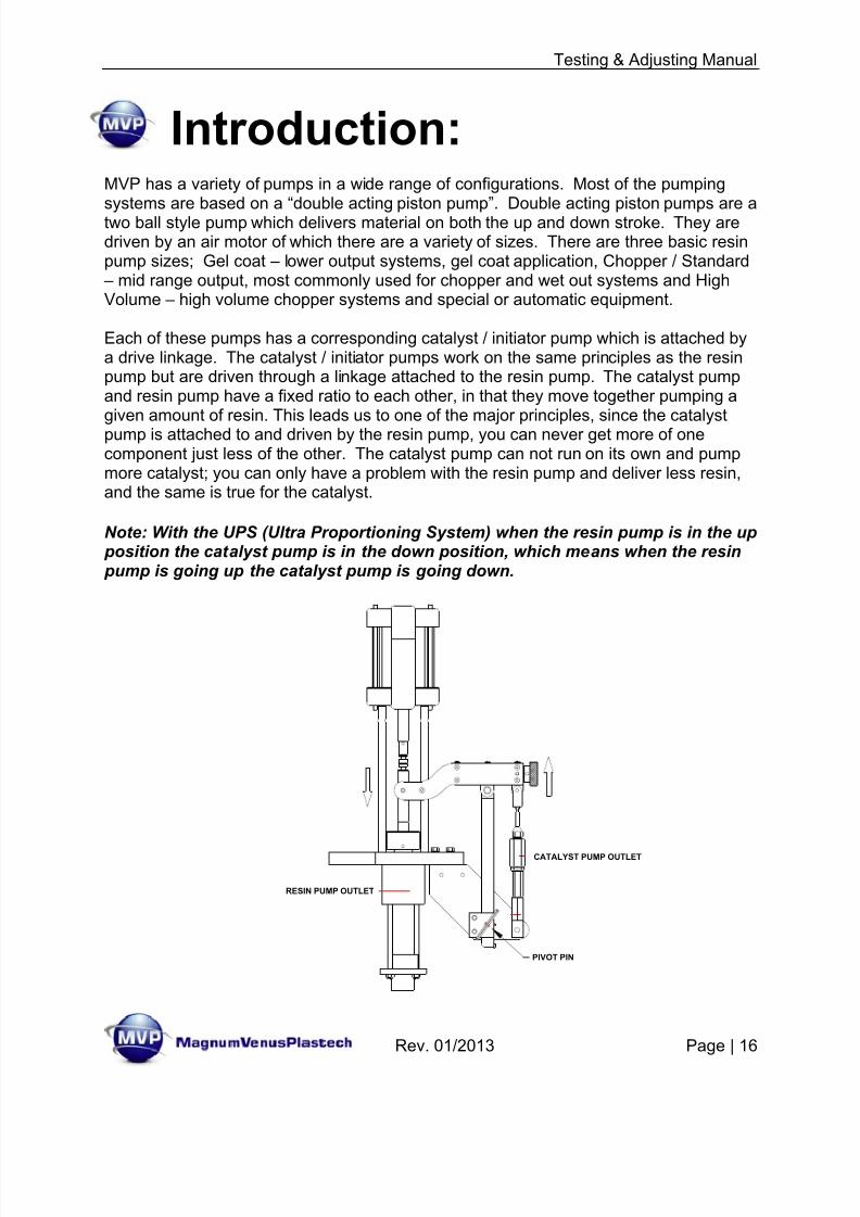
MVP has a variety of pumps in a wide range of configurations. Most of the pumpingsystems are based on a “double acting piston pump”. Double acting piston pumps are atwo ball style pump which delivers material on both the up and down stroke. They aredriven by an air motor of which there are a variety of sizes. There are three basic resinpump sizes; Gel coat – lower output systems, gel coat application, Chopper / Standard
– mid range output, most commonly used for chopper and wet out systems and HighVolume – high volume chopper systems and special or automatic equipment.
Each of these pumps has a corresponding catalyst / initiator pump which is attached bya drive linkage. The catalyst / initiator pumps work on the same principles as the resinpump but are driven through a linkage attached to the resin pump. The catalyst pumpand resin pump have a fixed ratio to each other, in that they move together pumping agiven amount of resin. This leads us to one of the major principles, since the catalystpump is attached to and driven by the resin pump, you can never get more of onecomponent just less of the other. The catalyst pump can not run on its own and pumpmore catalyst; you can only have a problem with the resin pump and deliver less resin,and the same is true for the catalyst.
Note: With the UPS (Ultra Proportioning System) when the resin pump is in the up position the catalyst pump is in the down position, which means when the resin pump is going up the catalyst pump is going down.
8/13/2019 Testing & Adjusting Your MVP Pumping System
http://slidepdf.com/reader/full/testing-adjusting-your-mvp-pumping-system 17/47
Testing & Adjusting Manual
Rev. 01/2013 Page | 17
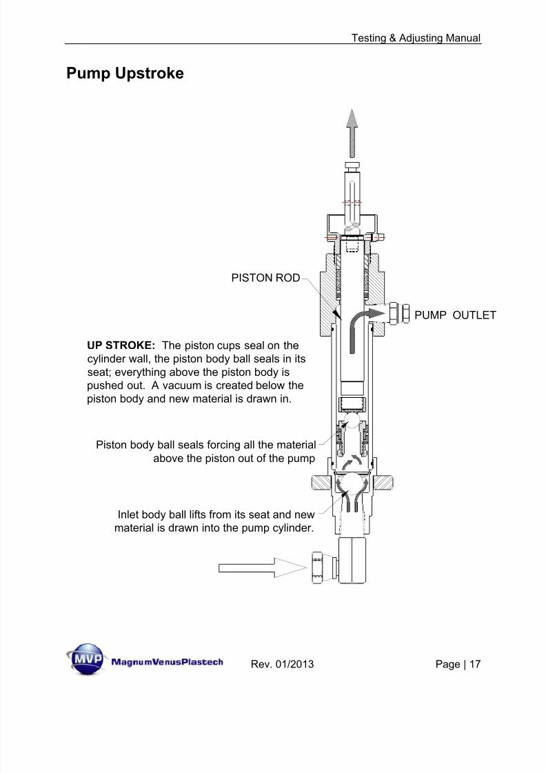
Pump Upstroke
UP STROKE: The piston cups seal on thecylinder wall, the piston body ball seals in itsseat; everything above the piston body ispushed out. A vacuum is created below thepiston body and new material is drawn in.
Inlet body ball lifts from its seat and new material is drawn into the pump cylinder.
Piston body ball seals forcing all the materialabove the piston out of the pump
PISTON ROD
PUMP OUTLET
8/13/2019 Testing & Adjusting Your MVP Pumping System
http://slidepdf.com/reader/full/testing-adjusting-your-mvp-pumping-system 18/47
Testing & Adjusting Manual
Rev. 01/2013 Page | 18
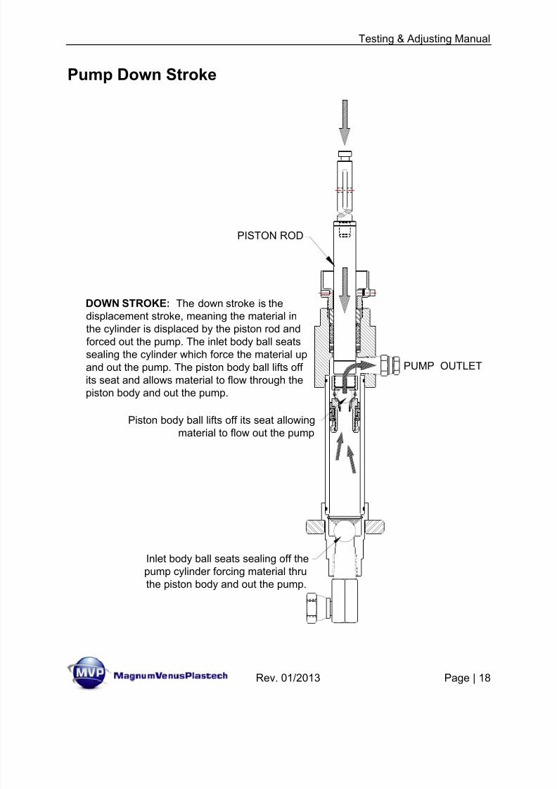
Pump Down Stroke
DOWN STROKE: The down stroke is thedisplacement stroke, meaning the material inthe cylinder is displaced by the piston rod andforced out the pump. The inlet body ball seatssealing the cylinder which force the material upand out the pump. The piston body ball lifts offits seat and allows material to flow through thepiston body and out the pump.
Piston body ball lifts off its seat allowingmaterial to flow out the pump
Inlet body ball seats sealing off the pump cylinder forcing material thru the piston body and out the pump.
PISTON ROD
PUMP OUTLET
8/13/2019 Testing & Adjusting Your MVP Pumping System
http://slidepdf.com/reader/full/testing-adjusting-your-mvp-pumping-system 19/47
Testing & Adjusting Manual
Rev. 01/2013 Page | 19
Establishing a Spray Fan:
If you know what is happening on both the upstroke and down stroke of the pump youwill know where to look when you have a problem. Adjusting your pumping system willbe easier with some understanding of pump ratios and fluid pressure.
Adjusting & Establishing a Fan Pattern
Magnum Venus Products spray equipment provides one of the most efficient methodsof quickly applying material to a surface or mold. To make the most of our low-pressurepumping systems and airless, internal mix guns, the operator must understand how toadjust the system for maximum efficiency.
Note: Because conditions and material vary widely, we cannot give you specificinstructions. We do offer guidelines and tests so that you can tune your Magnum
Venus Products equipment to meet your needs.
The basic idea is to use just enough pressure to the power head to establish the sprayfan, and no more.
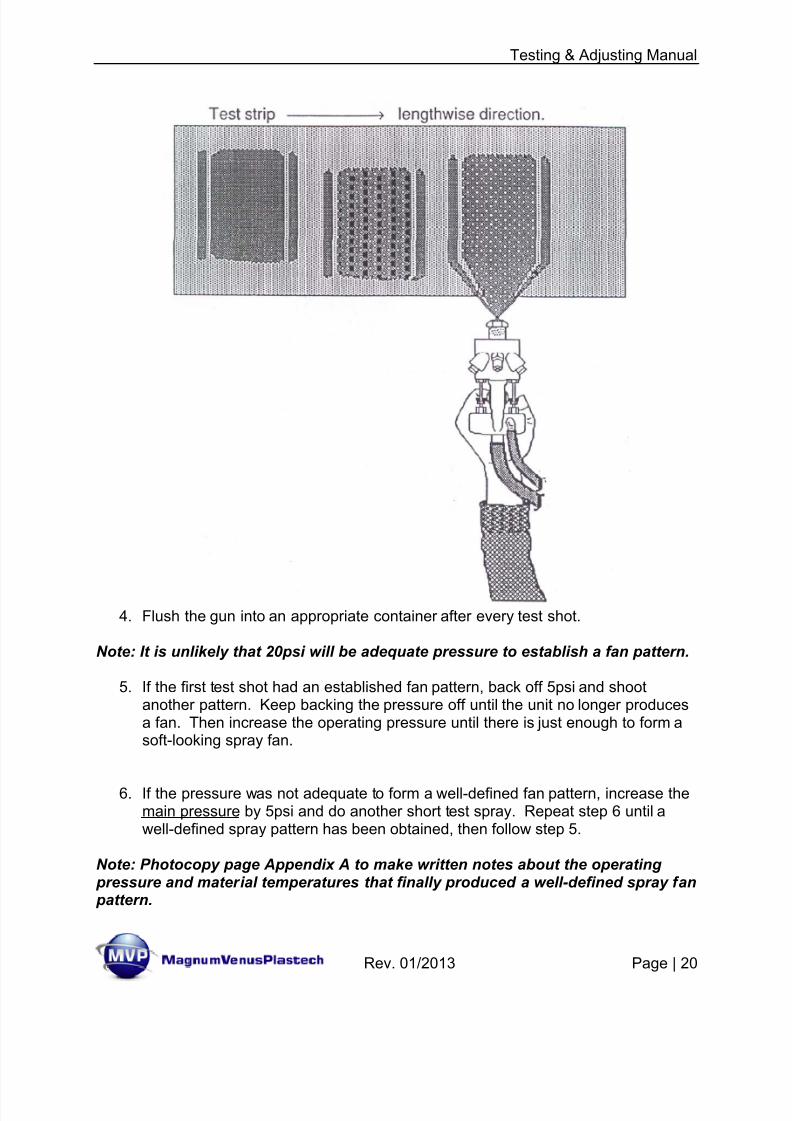
1. Lay out a strip of material for the test. For testing the material can be paper orcardboard.
2. Adjust the main pressure regulator until the operating pressure is 20psi.
Definition: Operating Pressure is the air pressure used to operate theresin/catalyst pump. The gauge and regulator are usually labeled “MainPressure” or “Pump Pressure”.
3. Do a short test spray on the material.
Note: To save material and make identification easier, spray perpendicular(across the material strip) tests.
8/13/2019 Testing & Adjusting Your MVP Pumping System
http://slidepdf.com/reader/full/testing-adjusting-your-mvp-pumping-system 20/47
Testing & Adjusting Manual
Rev. 01/2013 Page | 20
4. Flush the gun into an appropriate container after every test shot.
Note: It is unlikely that 20psi will be adequate pressure to establish a fan pattern.
5. If the first test shot had an established fan pattern, back off 5psi and shootanother pattern. Keep backing the pressure off until the unit no longer producesa fan. Then increase the operating pressure until there is just enough to form asoft-looking spray fan.
6. If the pressure was not adequate to form a well-defined fan pattern, increase themain pressure by 5psi and do another short test spray. Repeat step 6 until awell-defined spray pattern has been obtained, then follow step 5.
Note: Photocopy page Appendix A to make written notes about the operating pressure and material temperatures that finally produced a well-defined spray fan pattern.
8/13/2019 Testing & Adjusting Your MVP Pumping System
http://slidepdf.com/reader/full/testing-adjusting-your-mvp-pumping-system 21/47
Testing & Adjusting Manual
Rev. 01/2013 Page | 21
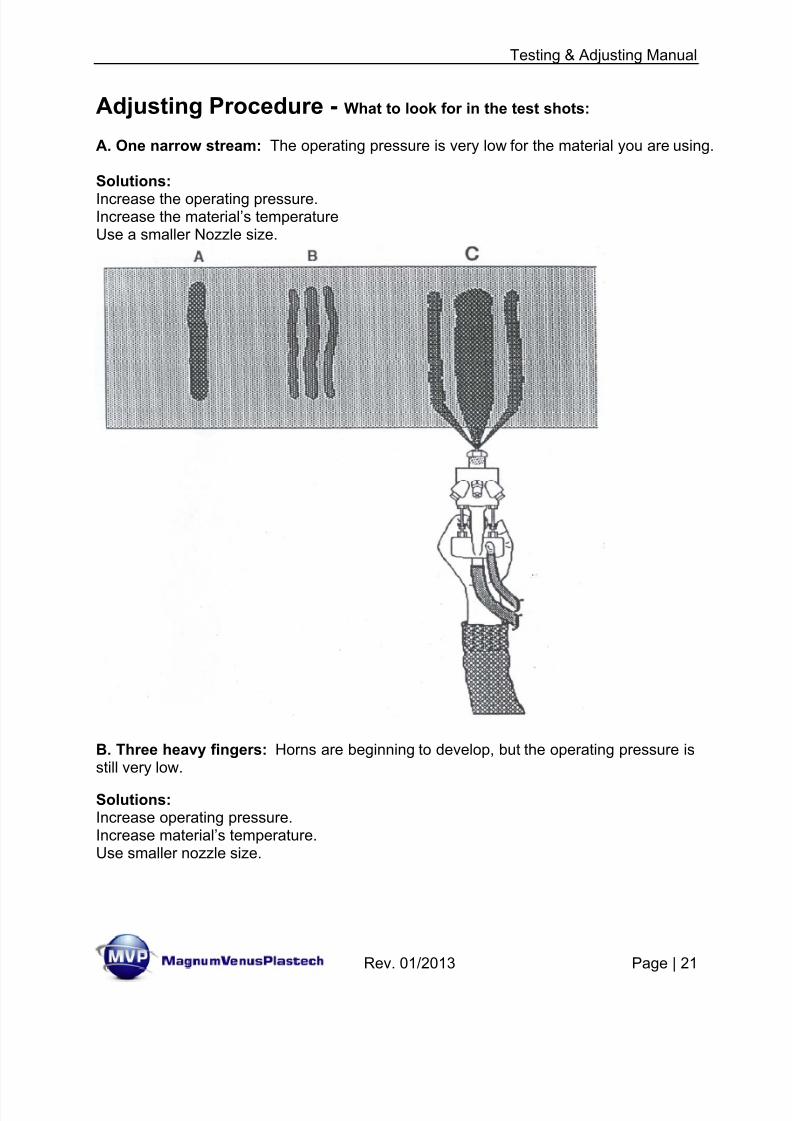
Adjusting Procedure - What to look for in the test shots:
A. One narrow stream: The operating pressure is very low for the material you are using.
Solutions:
Increase the operating pressure.Increase the material’s temperatureUse a smaller Nozzle size.
B. Three heavy fingers: Horns are beginning to develop, but the operating pressure isstill very low.
Solutions:Increase operating pressure.Increase material’s temperature.Use smaller nozzle size.
8/13/2019 Testing & Adjusting Your MVP Pumping System
http://slidepdf.com/reader/full/testing-adjusting-your-mvp-pumping-system 22/47
Testing & Adjusting Manual
Rev. 01/2013 Page | 22
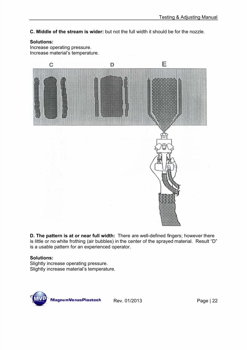
C. Middle of the stream is wider: but not the full width it should be for the nozzle.
Solutions:Increase operating pressure.Increase material’s temperature.
D. The pattern is at or near full width: There are well-defined fingers; however thereis little or no white frothing (air bubbles) in the center of the sprayed material. Result “D”
is a usable pattern for an experienced operator.
Solutions:Slightly increase operating pressure.Slightly increase material’s temperature.
8/13/2019 Testing & Adjusting Your MVP Pumping System
http://slidepdf.com/reader/full/testing-adjusting-your-mvp-pumping-system 23/47
Testing & Adjusting Manual
Rev. 01/2013 Page | 23
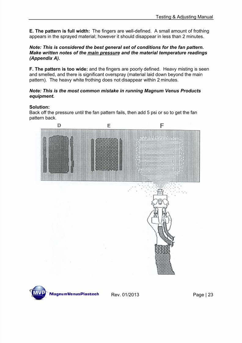
E. The pattern is full width: The fingers are well-defined. A small amount of frothingappears in the sprayed material; however it should disappear in less than 2 minutes.
Note: This is considered the best general set of conditions for the fan pattern.Make written notes of the main pressure and the material temperature readings
(Appendix A).
F. The pattern is too wide: and the fingers are poorly defined. Heavy misting is seenand smelled, and there is significant overspray (material laid down beyond the mainpattern). The heavy white frothing does not disappear within 2 minutes.
Note: This is the most common mistake in running Magnum Venus Productsequipment.
Solution:Back off the pressure until the fan pattern fails, then add 5 psi or so to get the fan
pattern back.
8/13/2019 Testing & Adjusting Your MVP Pumping System
http://slidepdf.com/reader/full/testing-adjusting-your-mvp-pumping-system 24/47
Testing & Adjusting Manual
Rev. 01/2013 Page | 24
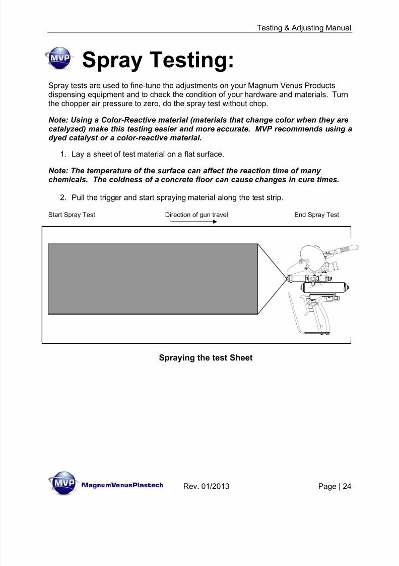
Spray Testing:
Spray tests are used to fine-tune the adjustments on your Magnum Venus Productsdispensing equipment and to check the condition of your hardware and materials. Turnthe chopper air pressure to zero, do the spray test without chop.
Note: Using a Color-Reactive material (materials that change color when they arecatalyzed) make this testing easier and more accurate. MVP recommends using adyed catalyst or a color-reactive material.
1. Lay a sheet of test material on a flat surface.
Note: The temperature of the surface can affect the reaction time of manychemicals. The coldness of a concrete floor can cause changes in cure times.
2. Pull the trigger and start spraying material along the test strip.
Start Spray Test Direction of gun travel End Spray Test
Spraying the test Sheet
8/13/2019 Testing & Adjusting Your MVP Pumping System
http://slidepdf.com/reader/full/testing-adjusting-your-mvp-pumping-system 25/47
Testing & Adjusting Manual
Rev. 01/2013 Page | 25
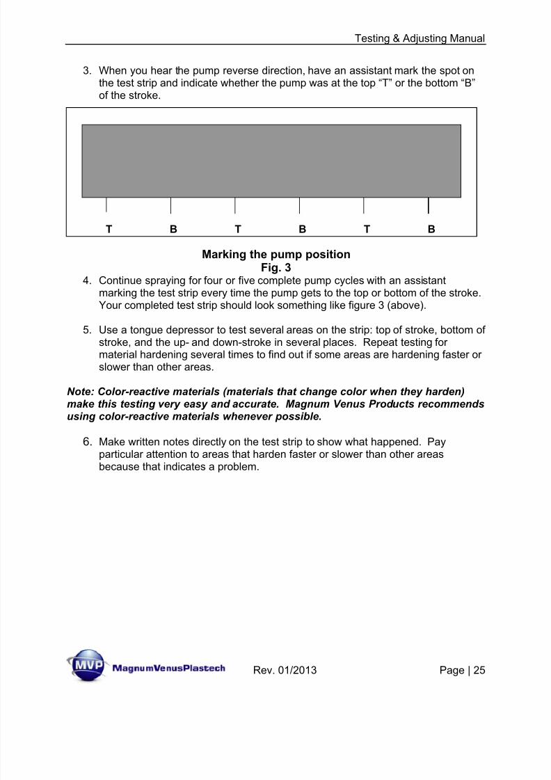
T B T B T B
3. When you hear the pump reverse direction, have an assistant mark the spot onthe test strip and indicate whether the pump was at the top “T” or the bottom “B”of the stroke.
Marking the pump position
Fig. 34. Continue spraying for four or five complete pump cycles with an assistantmarking the test strip every time the pump gets to the top or bottom of the stroke.Your completed test strip should look something like figure 3 (above).
5. Use a tongue depressor to test several areas on the strip: top of stroke, bottom ofstroke, and the up- and down-stroke in several places. Repeat testing formaterial hardening several times to find out if some areas are hardening faster orslower than other areas.
Note: Color-reactive materials (materials that change color when they harden)make this testing very easy and accurate. Magnum Venus Products recommendsusing color-reactive materials whenever possible.
6. Make written notes directly on the test strip to show what happened. Payparticular attention to areas that harden faster or slower than other areasbecause that indicates a problem.
8/13/2019 Testing & Adjusting Your MVP Pumping System
http://slidepdf.com/reader/full/testing-adjusting-your-mvp-pumping-system 26/47
Testing & Adjusting Manual
Rev. 01/2013 Page | 26
T B T B T B
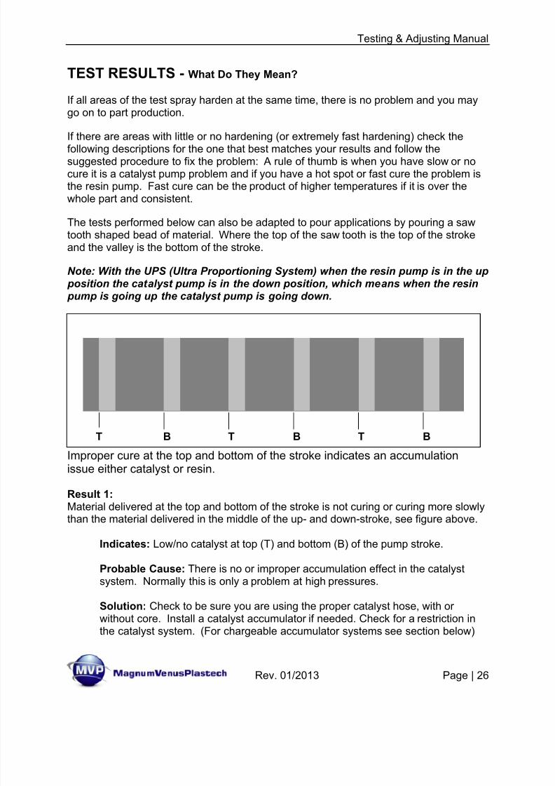
TEST RESULTS - What Do They Mean?
If all areas of the test spray harden at the same time, there is no problem and you maygo on to part production.
If there are areas with little or no hardening (or extremely fast hardening) check thefollowing descriptions for the one that best matches your results and follow thesuggested procedure to fix the problem: A rule of thumb is when you have slow or nocure it is a catalyst pump problem and if you have a hot spot or fast cure the problem isthe resin pump. Fast cure can be the product of higher temperatures if it is over thewhole part and consistent.
The tests performed below can also be adapted to pour applications by pouring a sawtooth shaped bead of material. Where the top of the saw tooth is the top of the strokeand the valley is the bottom of the stroke.
Note: With the UPS (Ultra Proportioning System) when the resin pump is in the up position the catalyst pump is in the down position, which means when the resin pump is going up the catalyst pump is going down.
Improper cure at the top and bottom of the stroke indicates an accumulationissue either catalyst or resin.
Result 1:Material delivered at the top and bottom of the stroke is not curing or curing more slowlythan the material delivered in the middle of the up- and down-stroke, see figure above.
Indicates: Low/no catalyst at top (T) and bottom (B) of the pump stroke.
Probable Cause: There is no or improper accumulation effect in the catalystsystem. Normally this is only a problem at high pressures.
Solution: Check to be sure you are using the proper catalyst hose, with orwithout core. Install a catalyst accumulator if needed. Check for a restriction inthe catalyst system. (For chargeable accumulator systems see section below)
8/13/2019 Testing & Adjusting Your MVP Pumping System
http://slidepdf.com/reader/full/testing-adjusting-your-mvp-pumping-system 27/47
Testing & Adjusting Manual
Rev. 01/2013 Page | 27
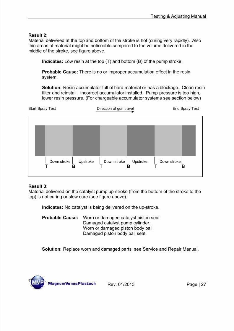
Down stroke Upstroke Down stroke Upstroke Down stroke
T B T B T B
Result 2:Material delivered at the top and bottom of the stroke is hot (curing very rapidly). Alsothin areas of material might be noticeable compared to the volume delivered in themiddle of the stroke, see figure above.
Indicates: Low resin at the top (T) and bottom (B) of the pump stroke.
Probable Cause: There is no or improper accumulation effect in the resinsystem.
Solution: Resin accumulator full of hard material or has a blockage. Clean resinfilter and reinstall. Incorrect accumulator installed. Pump pressure is too high,lower resin pressure. (For chargeable accumulator systems see section below)
Start Spray Test Direction of gun travel End Spray Test
Result 3:Material delivered on the catalyst pump up-stroke (from the bottom of the stroke to thetop) is not curing or slow cure (see figure above).
Indicates: No catalyst is being delivered on the up-stroke.
Probable Cause: Worn or damaged catalyst piston seal Damaged catalyst pump cylinder.Worn or damaged piston body ball.
Damaged piston body ball seat.
Solution: Replace worn and damaged parts, see Service and Repair Manual.
8/13/2019 Testing & Adjusting Your MVP Pumping System
http://slidepdf.com/reader/full/testing-adjusting-your-mvp-pumping-system 28/47
Testing & Adjusting Manual
Rev. 01/2013 Page | 28
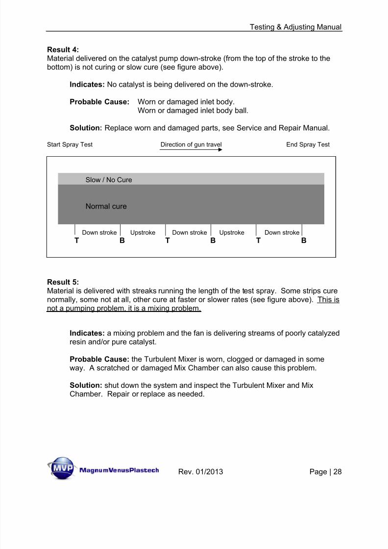
Down stroke Upstroke Down stroke Upstroke Down stroke
T B T B T B
Result 4:Material delivered on the catalyst pump down-stroke (from the top of the stroke to thebottom) is not curing or slow cure (see figure above).
Indicates: No catalyst is being delivered on the down-stroke.
Probable Cause: Worn or damaged inlet body. Worn or damaged inlet body ball.
Solution: Replace worn and damaged parts, see Service and Repair Manual.
Start Spray Test Direction of gun travel End Spray Test
Result 5:
Material is delivered with streaks running the length of the test spray. Some strips curenormally, some not at all, other cure at faster or slower rates (see figure above). This isnot a pumping problem, it is a mixing problem.
Indicates: a mixing problem and the fan is delivering streams of poorly catalyzedresin and/or pure catalyst.
Probable Cause: the Turbulent Mixer is worn, clogged or damaged in someway. A scratched or damaged Mix Chamber can also cause this problem.
Solution: shut down the system and inspect the Turbulent Mixer and MixChamber. Repair or replace as needed.
Normal cure
Slow / No Cure
8/13/2019 Testing & Adjusting Your MVP Pumping System
http://slidepdf.com/reader/full/testing-adjusting-your-mvp-pumping-system 29/47
Testing & Adjusting Manual
Rev. 01/2013 Page | 29
Down stroke Upstroke Down stroke Upstroke Down stroke
Start Spray Test Direction of gun travel End Spray Test
T B T B T B
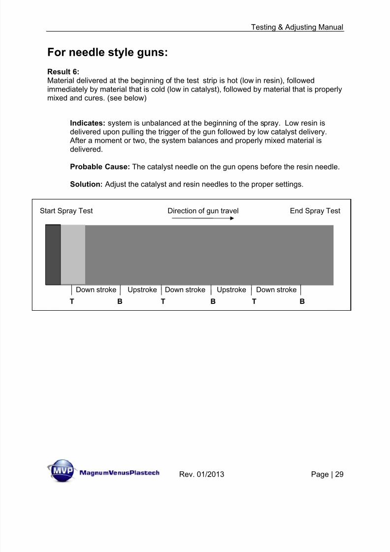
For needle style guns:
Result 6:Material delivered at the beginning of the test strip is hot (low in resin), followedimmediately by material that is cold (low in catalyst), followed by material that is properly
mixed and cures. (see below)
Indicates: system is unbalanced at the beginning of the spray. Low resin isdelivered upon pulling the trigger of the gun followed by low catalyst delivery.
After a moment or two, the system balances and properly mixed material isdelivered.
Probable Cause: The catalyst needle on the gun opens before the resin needle.
Solution: Adjust the catalyst and resin needles to the proper settings.
8/13/2019 Testing & Adjusting Your MVP Pumping System
http://slidepdf.com/reader/full/testing-adjusting-your-mvp-pumping-system 30/47
Testing & Adjusting Manual
Rev. 01/2013 Page | 30
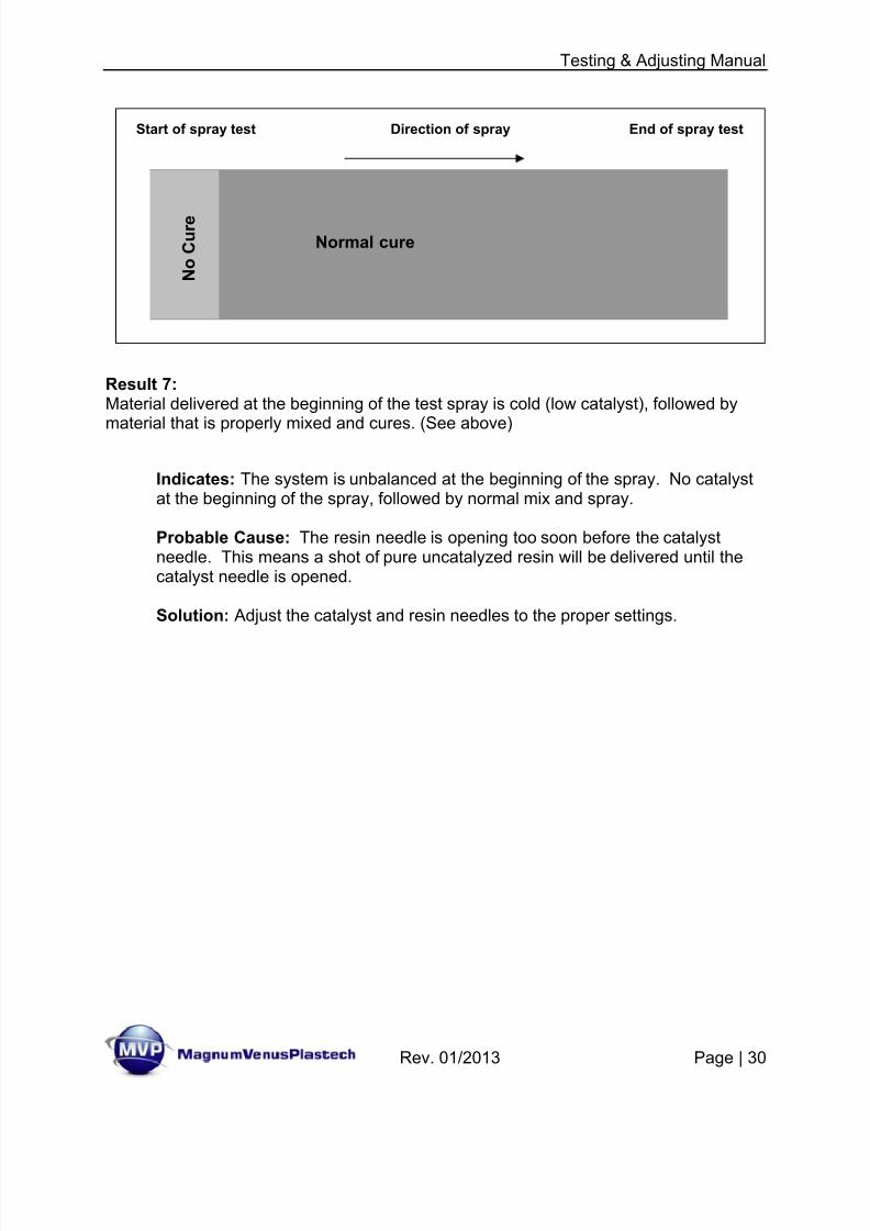
Result 7:Material delivered at the beginning of the test spray is cold (low catalyst), followed by
material that is properly mixed and cures. (See above)
Indicates: The system is unbalanced at the beginning of the spray. No catalystat the beginning of the spray, followed by normal mix and spray.
Probable Cause: The resin needle is opening too soon before the catalystneedle. This means a shot of pure uncatalyzed resin will be delivered until thecatalyst needle is opened.
Solution: Adjust the catalyst and resin needles to the proper settings.
Start of spray test Direction of spray End of spray test
Normal cure
N o
C u r e
8/13/2019 Testing & Adjusting Your MVP Pumping System
http://slidepdf.com/reader/full/testing-adjusting-your-mvp-pumping-system 31/47
Testing & Adjusting Manual
Rev. 01/2013 Page | 31
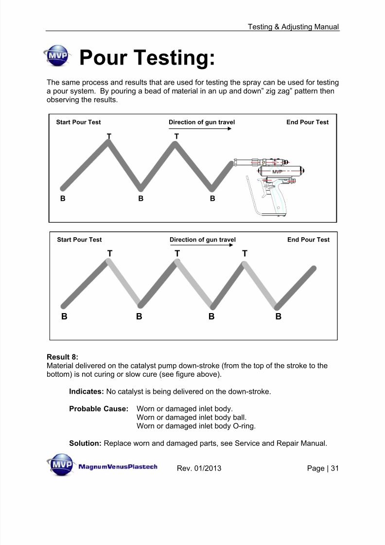
Pour Testing:
The same process and results that are used for testing the spray can be used for testinga pour system. By pouring a bead of material in an up and down” zig zag” pattern thenobserving the results.
Result 8:Material delivered on the catalyst pump down-stroke (from the top of the stroke to thebottom) is not curing or slow cure (see figure above).
Indicates: No catalyst is being delivered on the down-stroke.
Probable Cause: Worn or damaged inlet body. Worn or damaged inlet body ball.Worn or damaged inlet body O-ring.
Solution: Replace worn and damaged parts, see Service and Repair Manual.
Start Pour Test Direction of gun travel End Pour Test
B B B
T T
Start Pour Test Direction of gun travel End Pour Test
B B B B
T T T
Start Pour Test Direction of gun travel End Pour Test
B B B B
T T T
8/13/2019 Testing & Adjusting Your MVP Pumping System
http://slidepdf.com/reader/full/testing-adjusting-your-mvp-pumping-system 32/47
Testing & Adjusting Manual
Rev. 01/2013 Page | 32
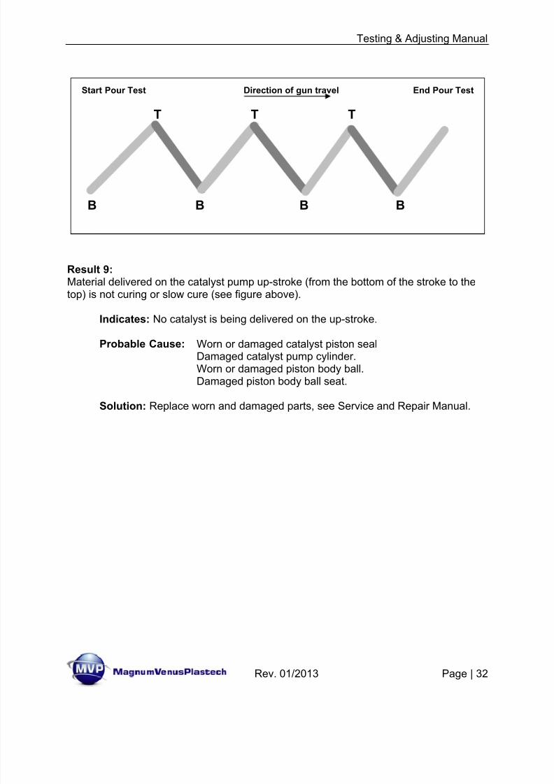
Result 9:Material delivered on the catalyst pump up-stroke (from the bottom of the stroke to thetop) is not curing or slow cure (see figure above).
Indicates: No catalyst is being delivered on the up-stroke.
Probable Cause: Worn or damaged catalyst piston seal Damaged catalyst pump cylinder.Worn or damaged piston body ball.Damaged piston body ball seat.
Solution: Replace worn and damaged parts, see Service and Repair Manual.
Start Pour Test Direction of gun travel End Pour Test
B B B B
T T T
8/13/2019 Testing & Adjusting Your MVP Pumping System
http://slidepdf.com/reader/full/testing-adjusting-your-mvp-pumping-system 33/47
Testing & Adjusting Manual
Rev. 01/2013 Page | 33
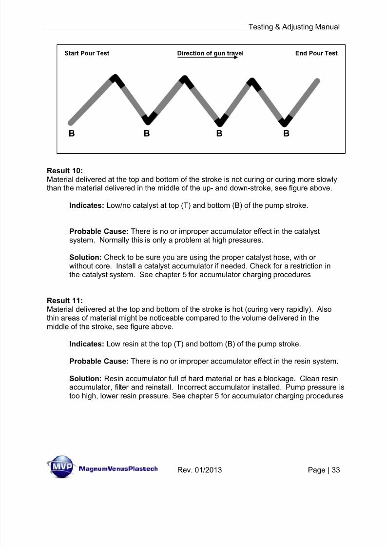
Result 10:Material delivered at the top and bottom of the stroke is not curing or curing more slowly
than the material delivered in the middle of the up- and down-stroke, see figure above.
Indicates: Low/no catalyst at top (T) and bottom (B) of the pump stroke.
Probable Cause: There is no or improper accumulator effect in the catalystsystem. Normally this is only a problem at high pressures.
Solution: Check to be sure you are using the proper catalyst hose, with orwithout core. Install a catalyst accumulator if needed. Check for a restriction inthe catalyst system. See chapter 5 for accumulator charging procedures
Result 11:Material delivered at the top and bottom of the stroke is hot (curing very rapidly). Alsothin areas of material might be noticeable compared to the volume delivered in themiddle of the stroke, see figure above.
Indicates: Low resin at the top (T) and bottom (B) of the pump stroke.
Probable Cause: There is no or improper accumulator effect in the resin system.
Solution: Resin accumulator full of hard material or has a blockage. Clean resinaccumulator, filter and reinstall. Incorrect accumulator installed. Pump pressure istoo high, lower resin pressure. See chapter 5 for accumulator charging procedures
Start Pour Test Direction of gun travel End Pour Test
B B B B
8/13/2019 Testing & Adjusting Your MVP Pumping System
http://slidepdf.com/reader/full/testing-adjusting-your-mvp-pumping-system 34/47
Testing & Adjusting Manual
Rev. 01/2013 Page | 34
Chargeable Accumulators:
Many applications will not require charging the accumulators; in those applications theaccumulator can be used as a surge chamber. These are low pressure spray or pourapplications where fluid pressures are medium to low.
In some cases only a line pressure charge on the resin accumulator will be necessary.These will be applications where a medium fluid pressure is being used, most likely aspray or a medium viscosity pour application. The line charge procedure uses thecharging hose attached to the air manifold.
For high fluid pressure applications charging the accumulators to 280psi to 300psi maybe required. These are applications using filled resins or spray putties. This will requirea charging pump or similar device a high pressure tank and regulators can also beused.
If you do a test and find it necessary to charge the resin accumulator or bothaccumulators repeat the test after performing the charging procedure to confirm aneven cure.
• Charging Procedures: Line Charge
1. Shut off air to the resin pump by either turning regulator to zero or turning thepump control valve to the off position.
2. Lock the gun in the on position over an appropriate container, or open the ballvalve at the bottom of the resin filter if one is installed.
Note: For catalyst charging lock the gun in the open position over an appropriatecontainer, or open the recirculation/dump valve on the manifold.
3. Relieve any existing charge by inserting a blunt object (allen wrench) into the topof the charging valve.
4. Push the quick coupling on charging hose onto the charging valve on top of theresin accumulator. Hold the in place for approximately 5 seconds.
Note: During charging of the accumulator, if air is heard exiting the front of thegun or appropriate valve, this indicates that the polyball in the accumulator is notseating properly. Repair the accumulator as needed.
5. Remove the charging hose from the resin accumulator. Check the top of theaccumulator for air leaks by applying a light fluid (water) to the top of theaccumulator valve body. If air leaks remove and repair charging valve.
8/13/2019 Testing & Adjusting Your MVP Pumping System
http://slidepdf.com/reader/full/testing-adjusting-your-mvp-pumping-system 35/47
Testing & Adjusting Manual
Rev. 01/2013 Page | 35
6. Close the gun and flush into appropriate container or close the resin return valve.
7. Normally in line charge applications the catalyst accumulator will not need to becharged. If needed follow the above procedures on the catalyst system.
a. Charging Procedures: Using Hand pump
8. Shut off air to the resin pump by either turning regulator to zero or turning thepump control valve to off position.
9. Lock the gun in the on position over an appropriate container, or open the ballvalve at the bottom of the resin filter if one is installed.
Note: For catalyst charging lock the gun in the open position over an appropriatecontainer, or open the recirculation/dump valve on the manifold.
10. Relieve any existing charge by inserting a blunt object (allen wrench) into the topof the charging valve.
11. Attach charging pump to the resin accumulator by connecting the black charginghose to the charging valve on top of the resin accumulator.
Note: Do not over tighten charging pump hose.
12. Pull the charging pump handle all the way out, connect air hose to male quickdisconnect on charging pump.
Note: not pulling out the handle of the charging pump before attaching the airline can cause damage to the charging pump or bodily injury.
13. Pump charging pump handle with steady even strokes until gauge on chargingpump read approximately 280psi.
Note: Gauge will only show accurate reading on the down / in stroke, while pressure is building (peak pressure). During charging of accumulator, if air isheard exiting the front of the gun or appropriate valve, this indicates that the polyball in the accumulator is not seating properly. Repair the accumulator as
needed.
8/13/2019 Testing & Adjusting Your MVP Pumping System
http://slidepdf.com/reader/full/testing-adjusting-your-mvp-pumping-system 36/47
Testing & Adjusting Manual
Rev. 01/2013 Page | 36
Note: A general rule of thumb
For Spray Application: Charge Accumulators to 280psi to 300psi.
Note: The above is a general rule of thumb some materials and applications
may require different charging pressures to achieve an even flow of material.Increase or decrease the charge by 5psi increments as required to fine tune theaccumulator charge.
14. Disconnect air hose form the charging pump and remove the charging pump hosefrom the resin accumulator. Check the top of the accumulator for air leaks byapplying a light fluid (water) to the top of the accumulator valve body. If air leaksremove and repair charging valve.
15. Close the gun and flush into appropriate container or close the appropriate. Forthe catalyst, close the recirculation valve on the catalyst manifold.
16. Repeat the above procedures for the catalyst accumulator.
a. Charging Procedures: Using High Pressure Tank & Regulators
17. Shut off air to the resin pump by either turning regulator to zero or turning thepump control valve to off position.
18. Lock the gun in the on position over an appropriate container, or open the ballvalve at the bottom of the resin filter.
Note: For catalyst charging lock the gun in the open position over an appropriate
container, or open the recirculation/dump valve on the manifold.
19. Relieve any existing charge by inserting a blunt object (allen wrench) into the top ofthe charging valve.
20. Attach charging system to the resin accumulator by connecting the black charginghose to the charging valve on top of the resin accumulator.
Note: Do not over tighten charging pump hose.
21. Open the main regulator on the top of the tank.
22. Set the desired pressure on the charging regulator attached to the charging valve.
23. Slowly open the ball valve connected to the charging hose to charge the accumulator. Allow approximately 5 seconds for charging before closing the valve again.
Note: During charging of the accumulator, if air is heard exiting the front of thegun or appropriate valve, this indicates that the polyball in the accumulator is notseating properly. Repair the accumulator as needed.
8/13/2019 Testing & Adjusting Your MVP Pumping System
http://slidepdf.com/reader/full/testing-adjusting-your-mvp-pumping-system 37/47
Testing & Adjusting Manual
Rev. 01/2013 Page | 37
Note: A general rule of thumb
For Spray Application: Charge Accumulators to 280psi to 300psi.
Note: The above is a general rule of thumb some materials and applicationsmay require different charging pressures to achieve an even flow of material.Increase or decrease the charge by 5psi increments as required to fine tune theaccumulator charge.
24. Disconnect charging hose from the resin accumulator. Check the top of theaccumulator for air leaks by applying a light fluid (water) to the top of theaccumulator valve body. If air leaks remove and repair charging valve.
25. Close the gun and flush into appropriate container or close the resin return valve
at the bottom of the filter. For the catalyst, close the recirculation valve on thecatalyst manifold.
26. Repeat the above procedures for the catalyst accumulator.

8/13/2019 Testing & Adjusting Your MVP Pumping System
http://slidepdf.com/reader/full/testing-adjusting-your-mvp-pumping-system 38/47
Testing & Adjusting Manual
Rev. 01/2013 Page | 38
Internal Start-up & Shut-down:
PRE-START CHECKLIST - Internal Mix System
FIRST TIME START-UP CHECK LIST - Internal Mix System
DAILY START UP - Internal Mix System
DAILY SHUT DOWN CHECKLIST - Internal Mix Systems
8/13/2019 Testing & Adjusting Your MVP Pumping System
http://slidepdf.com/reader/full/testing-adjusting-your-mvp-pumping-system 39/47
Testing & Adjusting Manual
Rev. 01/2013 Page | 39
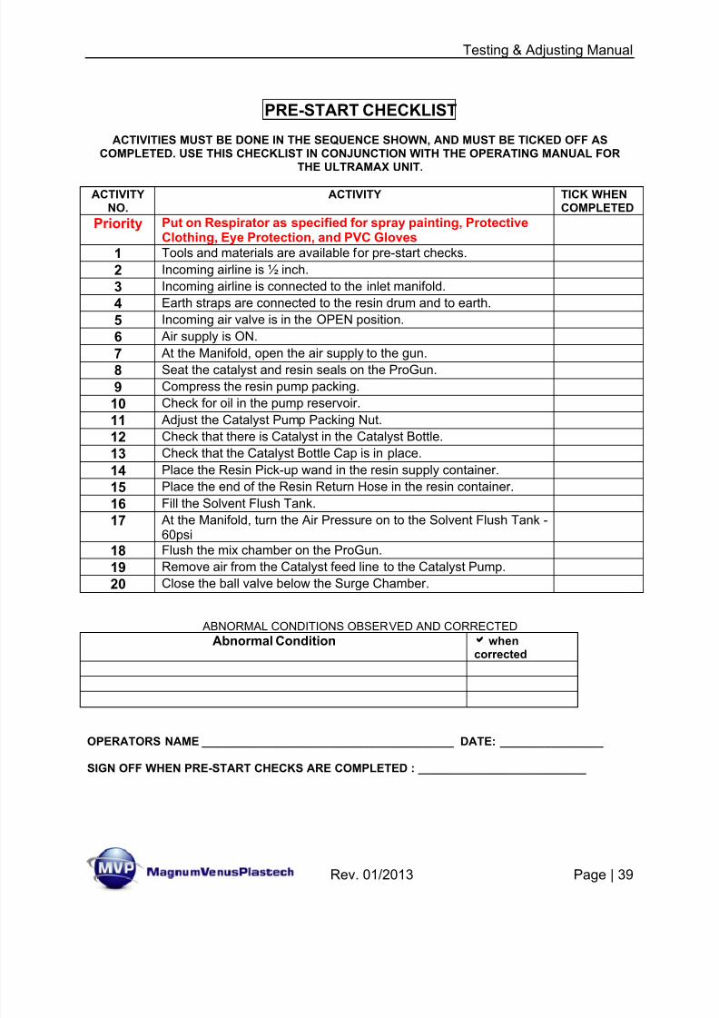
PRE-START CHECKLIST
ACTIVITIES MUST BE DONE IN THE SEQUENCE SHOWN, AND MUST BE TICKED OFF ASCOMPLETED. USE THIS CHECKLIST IN CONJUNCTION WITH THE OPERATING MANUAL FOR
THE ULTRAMAX UNIT.
ACTIVITYNO.
ACTIVITY TICK WHENCOMPLETED
Priority Put on Respirator as specified for spray painting, ProtectiveClothing, Eye Protection, and PVC Gloves
1 Tools and materials are available for pre-start checks.
2 Incoming airline is ½ inch.
3 Incoming airline is connected to the inlet manifold.
4 Earth straps are connected to the resin drum and to earth.
5 Incoming air valve is in the OPEN position.
6 Air supply is ON.
7 At the Manifold, open the air supply to the gun.8 Seat the catalyst and resin seals on the ProGun.
9 Compress the resin pump packing.
10 Check for oil in the pump reservoir.
11 Adjust the Catalyst Pump Packing Nut.
12 Check that there is Catalyst in the Catalyst Bottle.
13 Check that the Catalyst Bottle Cap is in place.
14 Place the Resin Pick-up wand in the resin supply container.
15 Place the end of the Resin Return Hose in the resin container.
16 Fill the Solvent Flush Tank.
17 At the Manifold, turn the Air Pressure on to the Solvent Flush Tank -
60psi18 Flush the mix chamber on the ProGun.
19 Remove air from the Catalyst feed line to the Catalyst Pump.
20 Close the ball valve below the Surge Chamber.
ABNORMAL CONDITIONS OBSERVED AND CORRECTED
Abnormal Condition aaaa whencorrected
OPERATORS NAME _______________________________________ DATE: ________________
SIGN OFF WHEN PRE-START CHECKS ARE COMPLETED : __________________________
8/13/2019 Testing & Adjusting Your MVP Pumping System
http://slidepdf.com/reader/full/testing-adjusting-your-mvp-pumping-system 40/47
Testing & Adjusting Manual
Rev. 01/2013 Page | 40
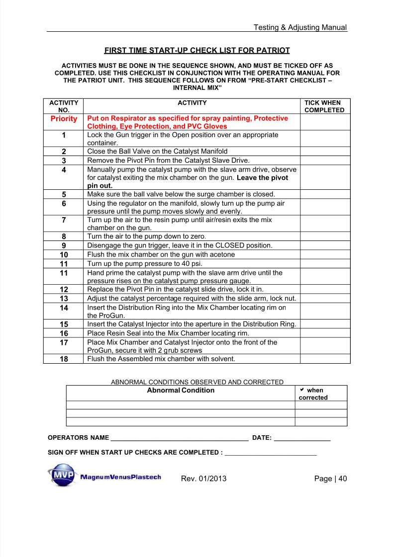
FIRST TIME START-UP CHECK LIST FOR PATRIOT
ACTIVITIES MUST BE DONE IN THE SEQUENCE SHOWN, AND MUST BE TICKED OFF ASCOMPLETED. USE THIS CHECKLIST IN CONJUNCTION WITH THE OPERATING MANUAL FOR
THE PATRIOT UNIT. THIS SEQUENCE FOLLOWS ON FROM “PRE-START CHECKLIST –INTERNAL MIX”
ACTIVITYNO.
ACTIVITY TICK WHENCOMPLETED
Priority Put on Respirator as specified for spray painting, ProtectiveClothing, Eye Protection, and PVC Gloves
1 Lock the Gun trigger in the Open position over an appropriatecontainer.
2 Close the Ball Valve on the Catalyst Manifold
3 Remove the Pivot Pin from the Catalyst Slave Drive.
4 Manually pump the catalyst pump with the slave arm drive, observefor catalyst exiting the mix chamber on the gun. Leave the pivotpin out.
5 Make sure the ball valve below the surge chamber is closed.6 Using the regulator on the manifold, slowly turn up the pump air
pressure until the pump moves slowly and evenly.
7 Turn up the air to the resin pump until air/resin exits the mixchamber on the gun.
8 Turn the air to the pump down to zero.
9 Disengage the gun trigger, leave it in the CLOSED position.
10 Flush the mix chamber on the gun with acetone
11 Turn up the pump pressure to 40 psi.
11 Hand prime the catalyst pump with the slave arm drive until thepressure rises on the catalyst pump pressure gauge.
12 Replace the Pivot Pin in the catalyst slide drive, lock it in.13 Adjust the catalyst percentage required with the slide arm, lock nut.
14 Insert the Distribution Ring into the Mix Chamber locating rim onthe ProGun.
15 Insert the Catalyst Injector into the aperture in the Distribution Ring.
16 Place Resin Seal into the Mix Chamber locating rim.
17 Place Mix Chamber and Catalyst Injector onto the front of theProGun, secure it with 2 grub screws
18 Flush the Assembled mix chamber with solvent.
ABNORMAL CONDITIONS OBSERVED AND CORRECTED
Abnormal Condition aaaa whencorrected
OPERATORS NAME _______________________________________ DATE: ________________
SIGN OFF WHEN START UP CHECKS ARE COMPLETED : __________________________
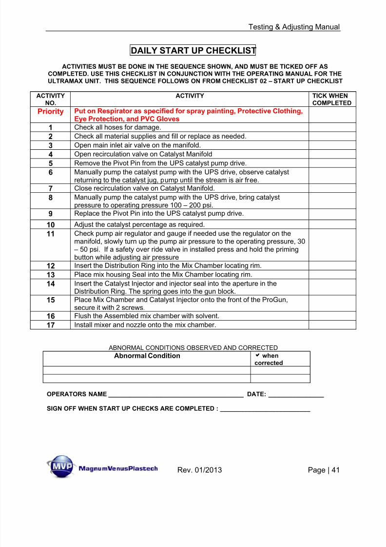
8/13/2019 Testing & Adjusting Your MVP Pumping System
http://slidepdf.com/reader/full/testing-adjusting-your-mvp-pumping-system 41/47
Testing & Adjusting Manual
Rev. 01/2013 Page | 41
DAILY START UP CHECKLIST
ACTIVITIES MUST BE DONE IN THE SEQUENCE SHOWN, AND MUST BE TICKED OFF ASCOMPLETED. USE THIS CHECKLIST IN CONJUNCTION WITH THE OPERATING MANUAL FOR THEULTRAMAX UNIT. THIS SEQUENCE FOLLOWS ON FROM CHECKLIST 02 – START UP CHECKLIST
ACTIVITYNO.
ACTIVITY TICK WHENCOMPLETED
Priority Put on Respirator as specified for spray painting, Protective Clothing,Eye Protection, and PVC Gloves
1 Check all hoses for damage.
2 Check all material supplies and fill or replace as needed.
3 Open main inlet air valve on the manifold.
4 Open recirculation valve on Catalyst Manifold
5 Remove the Pivot Pin from the UPS catalyst pump drive.
6 Manually pump the catalyst pump with the UPS drive, observe catalystreturning to the catalyst jug, pump until the stream is air free.
7 Close recirculation valve on Catalyst Manifold.8 Manually pump the catalyst pump with the UPS drive, bring catalystpressure to operating pressure 100 – 200 psi.
9 Replace the Pivot Pin into the UPS catalyst pump drive.
10 Adjust the catalyst percentage as required.
11 Check pump air regulator and gauge if needed use the regulator on themanifold, slowly turn up the pump air pressure to the operating pressure, 30
– 50 psi. If a safety over ride valve in installed press and hold the primingbutton while adjusting air pressure
12 Insert the Distribution Ring into the Mix Chamber locating rim.
13 Place mix housing Seal into the Mix Chamber locating rim.
14Insert the Catalyst Injector and injector seal into the aperture in theDistribution Ring. The spring goes into the gun block.
15 Place Mix Chamber and Catalyst Injector onto the front of the ProGun,secure it with 2 screws.
16 Flush the Assembled mix chamber with solvent.
17 Install mixer and nozzle onto the mix chamber.
ABNORMAL CONDITIONS OBSERVED AND CORRECTED
Abnormal Condition aaaa whencorrected
OPERATORS NAME _______________________________________ DATE: ________________
SIGN OFF WHEN START UP CHECKS ARE COMPLETED : __________________________
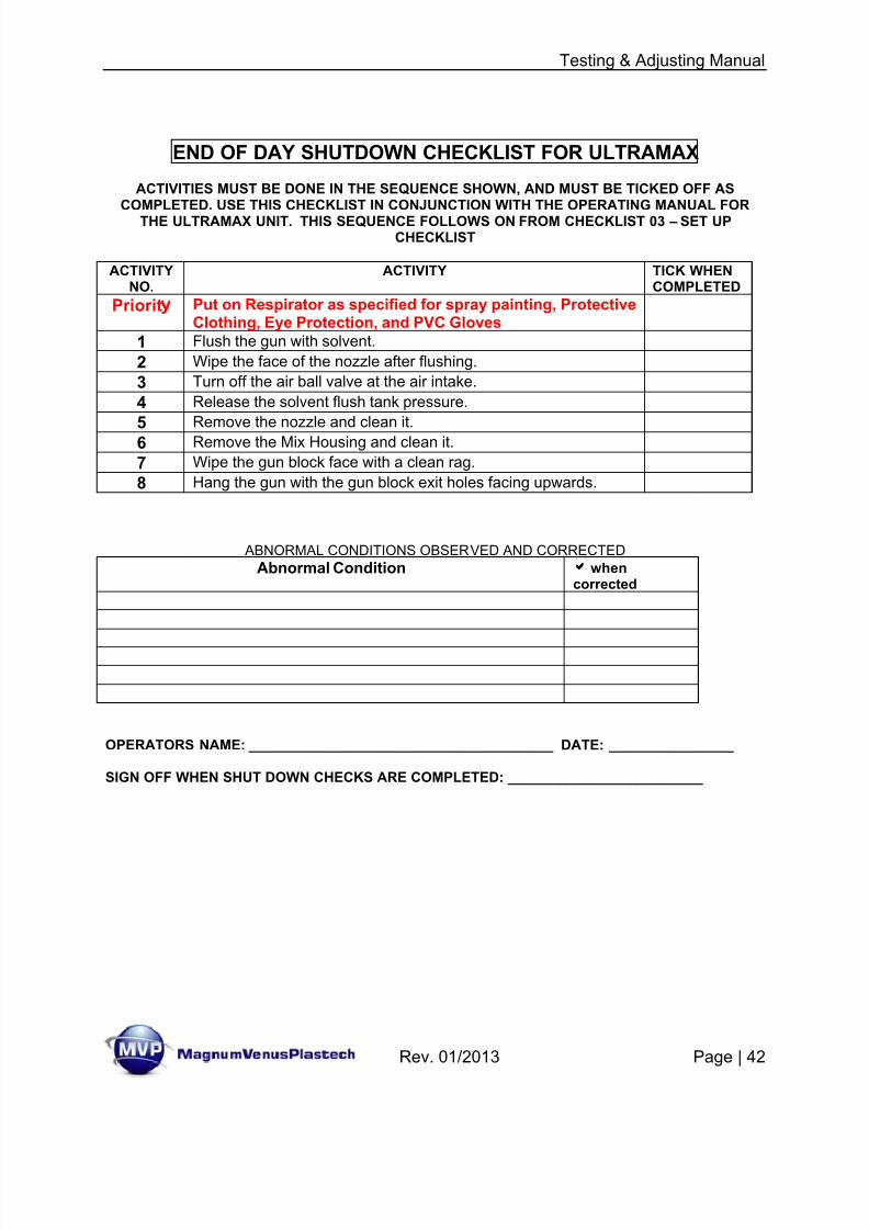
8/13/2019 Testing & Adjusting Your MVP Pumping System
http://slidepdf.com/reader/full/testing-adjusting-your-mvp-pumping-system 42/47
Testing & Adjusting Manual
Rev. 01/2013 Page | 42
END OF DAY SHUTDOWN CHECKLIST FOR ULTRAMAX
ACTIVITIES MUST BE DONE IN THE SEQUENCE SHOWN, AND MUST BE TICKED OFF ASCOMPLETED. USE THIS CHECKLIST IN CONJUNCTION WITH THE OPERATING MANUAL FOR
THE ULTRAMAX UNIT. THIS SEQUENCE FOLLOWS ON FROM CHECKLIST 03 – SET UPCHECKLIST
ACTIVITYNO.
ACTIVITY TICK WHENCOMPLETED
Priorit Put on Respirator as specified for spray painting, ProtectiveClothing, Eye Protection, and PVC Gloves
1 Flush the gun with solvent.
2 Wipe the face of the nozzle after flushing.
3 Turn off the air ball valve at the air intake.
4 Release the solvent flush tank pressure.
5Remove the nozzle and clean it.
6 Remove the Mix Housing and clean it.
7 Wipe the gun block face with a clean rag.
8 Hang the gun with the gun block exit holes facing upwards.
ABNORMAL CONDITIONS OBSERVED AND CORRECTED
Abnormal Condition aaaa whencorrected
OPERATORS NAME: _______________________________________ DATE: ________________
SIGN OFF WHEN SHUT DOWN CHECKS ARE COMPLETED: _________________________

8/13/2019 Testing & Adjusting Your MVP Pumping System
http://slidepdf.com/reader/full/testing-adjusting-your-mvp-pumping-system 43/47
Testing & Adjusting Manual
Rev. 01/2013 Page | 43
Appendix:
Test Notes – use the form below for recording the information from theSpray or Pour test.
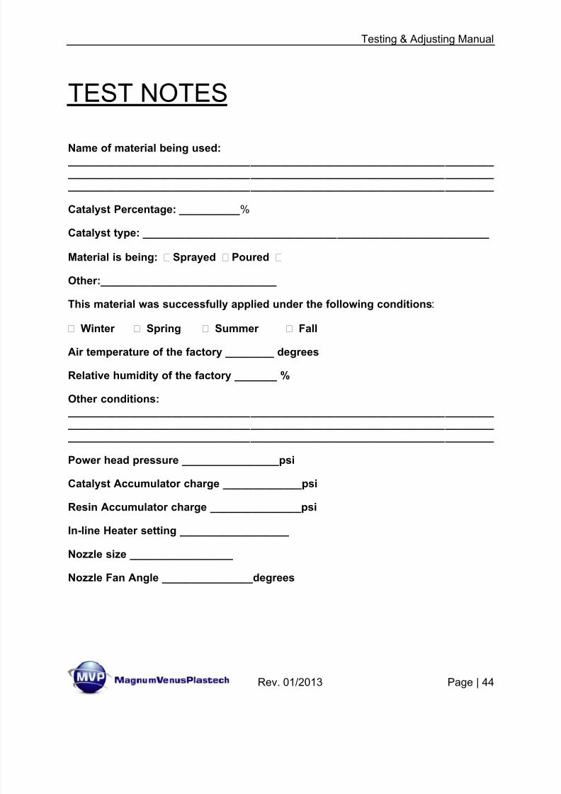
8/13/2019 Testing & Adjusting Your MVP Pumping System
http://slidepdf.com/reader/full/testing-adjusting-your-mvp-pumping-system 44/47
Testing & Adjusting Manual
Rev. 01/2013 Page | 44
TEST NOTES
Name of material being used: ______________________________________________________________________ ______________________________________________________________________ ______________________________________________________________________
Catalyst Percentage: __________ %
Catalyst type: _________________________________________________________
Material is being: Sprayed Poured
Other:_____________________________
This material was successfully applied under the following conditions:
Winter Spring Summer Fall
Air temperature of the factory ________ degrees
Relative humidity of the factory _______ %
Other conditions:
______________________________________________________________________ ______________________________________________________________________ ______________________________________________________________________
Power head pressure ________________psi
Catalyst Accumulator charge _____________psi
Resin Accumulator charge _______________psi
In-line Heater setting __________________
Nozzle size _________________
Nozzle Fan Angle _______________degrees

8/13/2019 Testing & Adjusting Your MVP Pumping System
http://slidepdf.com/reader/full/testing-adjusting-your-mvp-pumping-system 45/47
Testing & Adjusting Manual
Rev. 01/2013 Page | 45
Revision Information:
Rev. 01/2013 Updated the manual format and Address. We added theTerms & Conditions of Sale and Revision Informationsections to this manual. Added the Start-up and Shut-down sections

8/13/2019 Testing & Adjusting Your MVP Pumping System
http://slidepdf.com/reader/full/testing-adjusting-your-mvp-pumping-system 46/47
Testing & Adjusting Manual
Rev. 01/2013 Page | 46

8/13/2019 Testing & Adjusting Your MVP Pumping System
http://slidepdf.com/reader/full/testing-adjusting-your-mvp-pumping-system 47/47
Testing & Adjusting Manual
MAGNUM VENUS PLASTECH
CORPORATE HEADQUARTERS and MANUFACTURING11692 56
th Court * Clearwater, FL 33760 * Tel 727-573-2955 * Fax 727-571-3636
TECHNOLOGY CENTER and MANUFACTURING1862 Ives Ave. * Kent, WA 98032 * Tel 253-854-2660 * Fax 253-854-1666
MVP Plastech UKChilsworthy Beam, Gunnislake, Cornwall, PL18 9AT UK, * Tel: +44 (0) 1822 832621
Fax: +44 (0) 1822 833999
www.mvpind.com