Embed Size (px)
Citation preview
D J
.
IC TESTER DAVID H. DAGE
Test your digital ICs with this handy device. It a breakout box, pulse generator, pulse detector and more!
TESTING DIGITAL. CIRCUITS SHOULD BE
easy. After all, there are only two voltage levels involved. If the signal isn't high, then it's low. So your voltmeter or os- cilloscope should he all that you need. right? How wrong that is! Working with digital circuits requires a whole new gen- eration of test instruments ranging from the indispensable logic probe up to the sophisticated logic analyzers and emu- lators.
We'll show you how to build a device that's several digital test instruments rolled into one. It's a monitor, breakout box, comparator. pulse generator, and pulse detector. It can be used to trou- bleshoot digital circuits that contain 14-
and I6 -pin TTL or CMOS IC's. And it makes a great IC tester and trainer.
To use the analyzer for troubleshooting your digital circuits, you connect the ana- lyzer to the in- circuit IC using ribbon ca- ble and an IC test clip. If the analyzer is being used as a monitor. the logic level of each pin is displayed by an LED right next to a pictorial pinout of the IC. Each pin of the IC is accessible at the analyzer for
signal injection or simply for observation. That combination is hard to beat -it's cer- tainly better than tilting your head, hold- ing a databook open with your elbow, and jabbing spasmodically with a logic probe on what may very well be pin 10.
The analyzer gives you a remarkably simple way to troubleshoot an in- circuit IC. You can compare the outputs of the IC operating in- circuit to an IC of the same type that you know to be good. The good IC is inserted in the analyzer, and the power and input pins are connected to- gether using slide switches, while the out- puts are compared using EXCLUSIVE OR
(XOR) gates. If the LED's remain off, the in- circuit IC is good. Its as simple as that.
The analyzer can also be used to check IC's before installation. Slide switches are used to set logic levels on appropriate pins. while the built -in pulse generator is used to inject single or multiple pulses.
A look at the circuit The IC analyzer is made up of four
main parts: the power feed, a pulse gener- ator, a pulse stretcher, and a set of 16 pin-
monitor circuits. To explain the circuit operation as clearly as possible, we will discuss those sections separately.
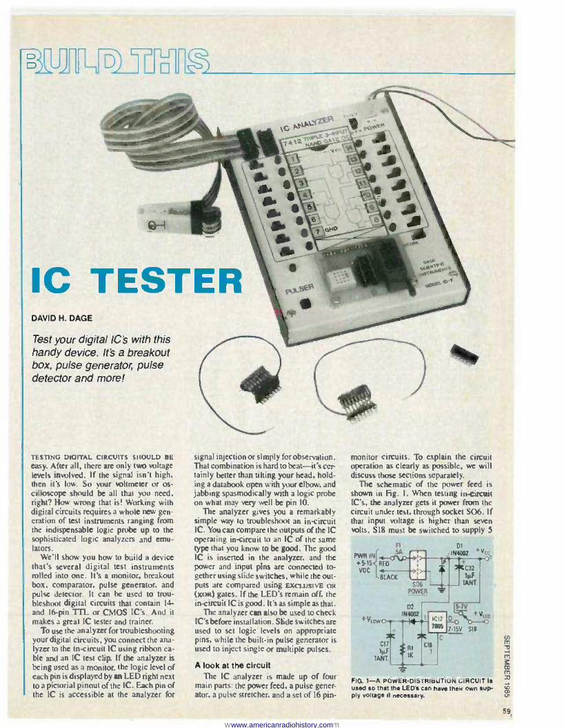
The schematic of the power feed is shown in Fig. I. When testing in- circuit IC's, the analyzer gets it power from the circuit under test, through socket S06. If that input voltage is higher than seven volts. 518 must be switched to supply 5
PWR IN
+5-15{ vDC
+Vt
Ft DI IN/08R Vcc . .
BLACK TANT S06
POWER r 02 5-7V
IN002 I Ic1z o' ' Viro . . . .
71105 7-15V
518
c C17 C 8
lyF RK
1
TANT.
FIG. 1 -A POWER -DISTRIBUTION CIRCUIT is used so that the LEDs can have their own sup- ply voltage if necessary.
59
sc TESTERDAVID H. DAGE
Test your digital Ie's with thishandy device. It's a breakoutbox, pulse generator, pulsedetector and more!
FIG. 1-A POWER-DISTRIBUTION CIRCUIT isused so that the LED's can have their own sup-ply voltage If necessary.
enm\J-lms:rnmJJ
+C32lv-F
'---+-1----' TANT.
CIS.1Rl
lK
+
CllIv-F
TA NT.
monitor circuits . To explain the circuitoperation as clearly as possible, we willdiscuss those sections separately.
The schematic of the power feed isshown in Fig.I. When testing in-circuitIC's, the analyzer gets it power from thecircuit under test , through socket506. Ifthat input voltage is higher than sevenvolts, 518 must be switched to supply 5
01IN4002 + Vcc
signal injection or simply for observation .That combinati on is hard tobeat-it's cer-tainly better than tilting your head, hold-ing a databook open with your elbow, andjabbing spasmodica lly with a logic probeon what may very well be pin 10.
The analyzer gives you a remarkablysimple way to troubleshoot an in-circuitIC. You can compare the outputs of the ICoperating in-circuit to an IC of the sametype that you know to be good. The goodIC is inserted in the analyzer, and thepower and input pins are connected to-gether using slide switches, while the out-puts are compared usingEXCLUSIVE OR
(XOR) gates.If the LED's remain off, thein-circuit IC is good. It's as simple as that.
The analyzer can also be used to checkIC' s before installation. Slide switches areused to set logic levels on app ropriatepins, while the built-in pulse generator isused to inject single or multiple pulses.
A look at the circuitThe IC analyzer is made up of four
main parts: the power feed, a pulse gener-ator, a pulse stretcher, and a set of 16 pin-
TESTING DIGITAL CIRCUITS SHOU LD BE
easy. After all, there are only two voltagelevels involved . If the signal isn't high,then it's low. So your voltmeter or os-cilloscope should be all that you need,right? How wrong that is! Working withdigital circuits requi res a whole new gen-eration of test instruments ranging fromthe indispensable logic probe up to thesophisticated logic analyzers and emu-lators.
We'll show you how to build a devicethat's several di gital test ins trumentsrolled into one . It 's a monitor, breakoutbox , comparator, pulse generator, andpulse detector. It can be used to trou-bleshoot digital circuits that contain 14-and 16-pinTIL or CMOS IC's. And itmakes a great IC tester and trainer.
To use the analyzer for troubleshootingyour digital circuits, you connect the ana-lyzer to the in-circ uit IC using ribbon ca-ble and an IC test clip. If the analyzer isbeing used as a monitor, the logic level ofeach pin is displayed by an LED right nextto a pictorial pinout of theIe. Each pin ofthe IC is accessible at the analyzer for
59
www.americanradiohistory.comwww.americanradiohistory.com

60
volts to the LED's. Otherwise. the current through them will be too high.
Supply voltage VI ow. is 0.8 volt less than Vcc and powers the XOR gates and the flip -flops used for the individual pin - monitor circuits. The voltage is derived through D2 and is filtered by C17. This provides a high threshold voltage of 2.1 volts during 5 -volt operation (which is necessary for TTL). The rest of the cir- cuits operate between 5 and 15 volts DC.
A block diagram of the pin -monitor logic is shown in fig. 2. while the sche- matic is shown in fig. 3. Since the ana- lyzer can be used to examine I6 -pin IC's. it must contain 16 pin -monitor circuits. Instead of showing the circuit 16 times. we have shown it once and have used lettered subscripts. Although that is dif- ferent from what we normally do in Ra- dio- Electronics, it should serve to make
FIG. 2 -THE PIN -MONITOR CIRCUIT Is shown here in a block diaaram.
R3
15 MEG
- Vcc
C29
001
W D3
114414/
R5
100K OC
K C27
900pF R7
68K l- 503
PULSE IN
Cao 001
K C28
100pF
14 D4
1N4141 R6
100K PC
V11 R4
1.5 MEG
IC9-e A4584
132 0
"D O
IC9-d
ASIA
06 1841148
IC9-c
K4584
R8
150K
C31
.1
1.5
R9
MEG IC9-a IC9-b
A45114 ANN
V1q R24
12K
Ve
LED17
R25
non
021
2842222
PG 5- SCHEMATIC OF THE PULSE STRETCHER. LEDI7 will light on both positive and negative transitions .
the circuit clearer. When referring to those parts, we'll use an "N" subscript. In Fig. 3. of course. N = I. (Since the XOR gate and S -R flip -flop are sections of IC's. we couldn't do that. So we'll mention here that the XOR gates in the pin -monitor cir- cuits are contained in ICI, 1C2, 105. and IC6. while the S -R flip -flops are con- tained in IC3. IC4, IC7. and 1C8.I Just
A SOCKETS `Vcc + view vc
SINGLE
FROM PULSE
519 1 CONTINUOUS_ 517
100 PPS STORE
R2
10K
FIG. 3- SCHEMATIC OF THE PIN MONITOR CIRCUIT. Note that because this circuit is repeated 16
times In the analyzer, the part numbers use lettered subscripts.
FIG. 4 -THE PULSE STRETCHER block dia- gram.
keep it in mind when you go through the Parts List.
When switch S., is in the out- position. the logic level on pin AN is compared with logic level on pin BN by the EXCLUSIVE OR
gate. If the two levels are different, the high output will set a 4043 flip -flop. Pulses less than 800 ns are considered glitches and are filtered out by R1.-N and CN.
A high output from the 4043 flip -flop
will turn on transistor Q,t, and thus the LED. Resistors RAN and RUN isolate and protect the analyzer circuits while RCN and RI)N limit current flow.
When switch S17 is in the sroRE position. the flip -flop can be reset man- ually using the PULSER switch, S19. When S17 is not in the STORE position. the flip - flop is continually reset by a 100 -pps pulse train.
Placing SN to the IN position. connects pin AN to pin BN. so that an in- circuit IC can be compared to an out -of- circuit test
IC. The analyzer has a built in pulse
stretcher and pulse generator. Both of those functions can be connected inde- pendently to any pin on the IC under test. The pulse stretcher will allow a single pulse or a fast pulse train can be caught and displayed on a separate LED. It is
highly sensitive to true logic changes but is immune to low -level noise.
A block diagram of the pulse stretcher is shown in Fig. 4, and its schematic is
shown in Fg. 5. As you can see. it uses five of the Schmitt -trigger inverters of IC9. The DC level on the input pins 13 and 11 of that IC is held midway between the switching point by R3 through R7. and diodes D3 and D4.
A negative transition discharges C27 and pulls pin 13 low. The capacitor is then charged through R3 until D3 conducts. The time constant of R3 and C27 coupled to the Schmitt trigger, produces a positive pulse of sufficient duration to then trigger the monostable flip -flop made up of R8. R9, C31 and two inverters, IC9 -a and IC9 - b. When triggered. output from pin 4 of 1C9 will go and remain high for approx-
06lN4148
0212N2222
07IC9-c lN4148セ T U XT
IC9-dセ T UX T
R2412K
C29.001
C30.001
will turn on transistor QN' and thus theLED . Resistors RANand RBNisolate andprotect the analyzer circuits while RCNand RDN limit current flow.
Whe n sw itch S17 is in theSTOREposition, the flip-flop can be reset man-ually using thePULSERswitch, S19. WhenSI7 is not in theSTORE position, the flip-flop is continually reset by a 100-pps pulsetrain.
Placing SN to theIN position , connectspin AN to pin BN, so that an in-circuit ICcan be compared to an out-of-circuit testIe.
Th e analyzer has abuilt in pulsestretcher and pulse generator. Both ofthose functions can be connected inde-pendentl y to any pin on the IC under test.The pulse stretcher will allow a sing lepulse or a fast pulse train can be caughtand displayed on a separate LED. It ishighly sensi tive to true logic changes butis immune to low-level noise .
A block diagram of the pulse stretcheris shown in Fig . 4 , and its schematic isshown in Fig . 5 . As you can see, it usesfive of the Schmitt-trigger inverters ofIC9. The DC level on the input pins 13 andII of that IC is held midway between theswitching point by R3 through R7, anddiodes03 and 0 4.
A nega tive transitiondischarges C27and pulls pin 13 low. Thecapacitoris thenchargedthrough R3 until 0 3conducts.The time constant of R3 and C27 coupledto the Schmitt trigger, produces a positivepulse of sufficie nt duratio n to then triggerthe monostable flip-flop made up of R8,R9, C3 1and two inverters, IC9-a and IC9-b. When triggered, output from pin 4 ofIC9 will go and remain high for approx-
C31.1
R768K
R6lOOK
R5lOOK
IC9·a IC9-blH 584 セ T U X T
03IN4148
04lN4148
R3 + Vee1.5 MEG
R41.5 MEG '="
IC9-eセ T UX T
'-- -!-- セ Q S セ x G R セ M MM ⦅ ⦅ ャ セ
C28100pF
C2l100pF
R91.5 MEG
thecircuit clearer. When referringto thoseparts, we'll use an" N" subscript. In Fig.3, of course,N = I. (Since theXOR gateand S-R flip-flop aresections of Ie's, wecouldn't do that. So we'll menti on herethat theXOR gates in the pin-monitorcir-cuits are contained in ICI , IC2, IC5, andIC6, whi le the S-R flip-flops are con-tained in IC3, IC4, IC7 , and IC8.) Just
keep it in mind when you go through theParts List.
WhenswitchSNis in the OUT position ,the logic level on pin ANis comparedwithlogic level on pin BNby the EXCLUSIVEORgate . If the two levels are different , thehigh output will set a 4043 fl ip-flop.Pulses less than 800 ns are consideredglitches and are filtered out by RFN andCN'
A high output from the 4043flip-flop
FIG. 5-SCHEMATIC OF THE PULSE STRETCHER. LED17 will light on both positive and negat ivetransitions.
BSOCKETS
RBI1.5K
RAt 21.5K
LED1-LED16
REt4.7K
OUT
IN
ASOCKETS + Vee
{
SINGLEFROM PULSE- - - --
S19 CONTINUOUS_ j' S17100 PPS STORE
PULSER.........-<roo-<:}--"= o.:-.J
volts to theLED's. Otherwise,the currentthrough them will be too high .
Supply voltageV l セw is 0 .8 volt lessthan Vcc and powers theXOR gates andthe flip-flops used for the individual pin-monitor circuits . The voltage is derive dthrough 0 2 and is filtered by C17. Thisprovide s a high threshold voltage of 2.1volts durin g 5-volt operation (which isnecessary forTTL). The rest of the cir-cuit s operate between 5 and 15 voltsDe.
A block diagram of the pin-monitorlogic is shown in Fig. 2 , while the sche -matic is shown in Fig . 3. Since the ana-lyzer can be used to exami ne 16-pi n Ie's,it must contain 16 pin-monitor circuits .Instead of showing the circuit 16 times ,we have shown it once and have usedlettered subscripts . Although that is dif-ferent from what we normally do inRa-dio-Electronics , it should serve to make
FIG. 4-THE PULSE STRETCHER block dia -gram.
FIG. 3-SCHEMATIC OF THE PIN MONITOR CIRCUIT. Note that because th is circu it is repeated 16times in the analyzer, the part numbers use lettered subscrlpts.
FIG. 2-THE PIN-MONITOR CIRCUIT Is show nhere in a block dlaaram.
(J)
ozoa:I-oW-lWao-ca:
60
www.americanradiohistory.comwww.americanradiohistory.com

PUSH
BUTTON
SOO
--r 100 ppS OSC
TIME DELAY
PULSE
GEN r HIGH
F.
Low DRIVER POWER
OUTPUT
SENSE INPUT
STATE
SENSE
HIGH DRIVER
Vcc
F G. 6 -THE PULSE GENERATOR block dia- gram.
imately 50 ms. This output drives the LEDI7.
Positive transitions charge C28 and pulls pin 11 of IC9 high. An output blink of LEDI7 is produced in a similar fashion. Capacitors C29 and C30 hold the midway reference voltage constant, while diodes D6 and D7 isolate the two outputs from pin 8 and pin 12 of IC9.
The pulse generator can be used to change the logic level voltage to the op- posite state for a short time, overriding any logic output that is in control. Inject- ing pulse(s) to stimulate digital circuitry is indispensable for troubleshooting. The
Vcc S19
C19
PULSER R12
7 D5 L MEG * 1141118
ot
C21
+Vcc
R15
LOOK
R16
47K
817
12K
R13
1K
3101
3301
duration of the pulse is so short that no damage is donc to the output device. The pulse output can be either a single pulse of a 100 pps (Pulse- Per -Second) pulse train.
A block diagram of the pulse generator is shown in Fig. 6, while its schematic is shown in Fg. 7. The logic level of the external circuit is sensed through RI6, and is fed to the DATA input of flip -flop ICIO -b. When switch S19 is pushed, a
single positive pulse is generated by CI9 and RI3, setting flip -flop ICIO -a.
A multivibrator that generates a 100 -
pps squarewave is made up of RIO. C21, and IC9 -f, a Schmitt -trigger inverter. The squarewave is fed to AND gate ICI I -c. If S19 is held closed, C20 charges thni R12 and, after about 2 seconds. turns on ICI I- c. That allows flip -flop ICIO -a to be clocked as long as S19 is pushed. When S19 is released, C20 rapidly discharges thru D5 and RI1. Flip -flop ICIO -a resets
2
R26
R27
BLACK I R42
LEAD 1143
1128 i R44
R41
16
R26-R41-220 1
"SHORTING" PWG
RED
LEAD 1157
2
16 R42- R57 -150K
-PULL uP" PLUG
FIG. 8 -THE PULL -UP AND SHORTING PLUGS are shown here schematically.
6
D 01 +- R14
12K
IC10 a
44013
R T C21 220
pf
9
8 ' 13
S
D
IC10-b
01013
0
0
75 C23 100pF
C22
001
C25
001
____)
'.4011
S17
STORE
R19 Vcc 19 A
10011 W 017
2/43702
R20
10011
R23
1K
C26
001
Vc
019
2143102 R22
10011 W R21
10011
020 2144275
OOO S03
PULSE OUT
FIG. 7- SCHEMATIC OF THE PULSE GENERATOR. The generators output is sent to the solderless breadboard socket.
PARTS LIST All resistors 1/4-watt. 5%
RA1 -RAIS. RBI-R[316-1500 ohms Rct -RC16- 12,000 ohms R01 -RD16 -220 ohms RE1 -RE18 -4700 ohms RFI -RF16- 15.000 ohms Rl. R11. R13, R18, R23 -1000 ohms R2- 10.000 ohms R3. R4, R9-1.5 megohms R5, R6, R15- 100.000 ohms R7 -68.000 ohms R8. R42- R57- 150.000 ohms R10- 330,000 ohms R12 -4.7 megohms R14, R17. R24- 12.000 ohms R16- 47.000 ohms R17- 12,000 ohms R19 -R22 -100 ohms R25. R26 -R41 -220 ohms
Capacitors CAI- CA16 -15 pF. ceramic disc C17. C20, C32- 1.0µF, 25 volts, tantalum C18. C21, C31 -0.1 ceramic disc C19-0.01 ceramic disc C22. C25 -C26. C29, C30-0.001 µF, ce-
ramic disc C23. C27, C28 -100 pF ceramic disc C24 -220 pF polystyrene
Semiconductors IC1,1C2, 105, 106 -4070 quad EXCWSIVE
on gate 1C3 -1C4. IC7, IC8 -4043 quad 3 -state
latches 1C9 -4584 Hex Schmitt trigger inverters IC10-4013 dual D -type flip -flop IC11 -4011 quad NAND gate IC12 -7805 5 -volt regulator (TO -220
case) Q1 -016. Q21- 2N2222 017, 019-- 2N3702 018, Q20- 2N4275 Dl. D2- 1N4002 D3-D7-1N4148 LED1- LED17- standard red LED
Other components S1 -S18 -SPDT slide switches S19- Pushbutton switch, normally open S01. S02. SO4- wirewrap type. 16 -pin
DIP sockets S03- Solderless breadboard strip (4 . 4) S05 -ZIF socket S06-2 -pin power connector S07 -20 -pin single -row female header
Miscellaneous: Main PC board: B -sock- et PC board: IC sockets, cabinet. DIP headers for plugs. etc.
The following are available from Dage Scientific Instruments. P.O. Box 144, Valley Springs, CA 95252: Plated -thru PC boards. IC pin -out cards and de- tailed instructions (order number IC -18). 530.00 plus 52.00 shipping. Complete kit of parts less chassis, DIP - clip cable. and sockets (order number IC-20). 579.95 plus 53.00 shipping. Complete kit, includes assembled dip - clip cable, zero insertion force socket, even solder (order number IC -22). 5119.00 plus 54.00 shipping. California residents please add sales tax. Coun- tries other than U.S.A. and Canada. please add 58.00.
61
enm""tJ-Ims:OJmIJ
Other componentsS1 -S1 8-SPDT slide switchesS19-Pushbutton switch, normally openS01, S02, S04-wirewrap type, 16-pin
DIP socketsS03-Solderless breadboard strip (4 x 4)S05--ZIF socketS06-2-pin power connectorS07-20-pin single-row female header
Miscellaneous: Main PC board; B-sock-et PC board; IC sockets, cabinet, DIPheaders for plugs, etc.
The following are available from DageScientific Instruments, P.O. Box 144,Valley Springs, CA 95252: Plated- thruPC boards, IC pin-out cards andde-tailed inst ruc t ions (order numberIC-18), $30.00 plus $2.00 sh ip ping.Complete kit of parts less chassis, DIP-clip cable , and sockets (order 'numberIC-20), $79.95 plus $3.00 shipping.Comp lete kit , includes assem bled dip-clip cable, zero insert ion force socket,even solder (order number IC-22),$119.00 plus $4.00 shipping. Californiaresidents please add sales tax: Coun-tries other than U.S.A. and Canada,please add $8.00.
CapacitorsCA1-CA16- 15 pF, ceramic discC17, C20, C32-1 .0 p.F,25 volts, tantalumC18, C21, C31-Q.1 ceramic discC19-Q.01 ceramic discC22, C25-C26, C29, C3O-Q.001 f.lF, ce-
ramic discC23, C27, C28-100 pF ceramic discC24-220 pF polystyrene
SemiconductorsIC1,IC2, IC5, IC6-4070 quad EXCLUSIVE
O R gateIC3-IC4, IC7, IC8- 4043 quad 3-state
latchesIC9-4584 Hex Schmitt trigger invertersIC10-4013 dual D-type flip-flop セ
IC11-4011 quad NAND gateIC12-7805 5-vo lt regulator (TO-220
case) .0 1-o16,021-2N22220 17, 0 19- -2N3702018, 02D-2N4275D1 , D2- 1N4002D3-D7- 1N41 48LED1-LED17-standard red LED
PARTS LISTAll resistors V4-watt , 5%
RA1-RA16' rbQMr セ Q V M QUPP ohmsRC1-Rc1 6- 12,OOO ohmsRD1-RD16-220 ohmsRE1-RE1 6-4700 ohmsRF1-RF 16-15,OOO ohmsR1, R1 1, R13, R18, R23-1000 ohmsR2- 10,OOOohmsR3, R4, R9-1.5 megohmsR5, R6, R15--100,OOO ohmsR7-68,OOO ohmsR8, R42-R57-150,OOO ohmsR1D-330,OOOohmsR12-4.7 megohmsR1 4, R17, R24-12,OOO ohmsR16-47,OOO ohmsR17- 12,OOO ohmsR19-R22- 100 ohmsR25, R26-R41-220 ohms
R42
R43
R44
I セセャ 0 16+t¥T
R42-R57-150K"PULL UP"PWG
0172N3102
REOLEAD
+vR19 cc
lOOn
BLACKLEAD
IC22.001
1 R26
2 R27
3 R2B
Q セ セ PR26-R41-220n
"SHORTING" PWG
FIG. 8- THE PULL-UP AND SHORTING PLUGSare shown here schematically.
duration of the pulse is so short that nodamage is done to the output device . Thepulse output can be either a single pulse ofa 100 pps (Puls e-Per-Second) pulse train .
A block diagram of the pulse generatoris shown in Fig. 6, while its schematic isshown in Fig. 7. The logic level of theexternal circuit is sensed through R16,and is fed to theDATA input of flip-floplelO-b. When switch S19 is pushed , asingle positive pulse is generated by CI9and R13, setting flip-flop ICIO-a.
A multivibrator that generates a 100-pps squarewave is made up of RIO, C21,and IC9-f, aSchmitt-trigger inverter. Thesquarewave is fed toAND gate ICIl-c . IfS19 is held closed, C20 charges thru RI2and, after about 2 seconds,turns on ICII -c. That allows flip-flop ICIO-a to beclocked as long as SI9 is pushed . WhenS19 is released , C20 rapidlydischargesthru D5 and Rii. Flip-flop ICIO-a resets
R4
ICIO-aY,4013
R131K
...-----------------<HO-O-O-OS03
PULSE OUT
6
5 D S 01-'-'_""""-'3 C
POWEROUTPUTSENSEINPUT
05IN4t48
A10330K
A10
ICIO-bY, 401 :1.. 12
o
I C23'=' lOOpF
A1712K
R15lOOK
R1647K
8 ':'
........_ +-19 S 13r D 0
11 C
+v S19ccPULSER R12
+セ t セセgLo +
Rll C20r1pJ .
lK '=' TANT.':'
+Vcc
FIG. 7-SCHEMATIC OF THE PULSE GENERATOR. The genera tor's output Is sent to the so lder lessbreadboard socket.
FIG. 6-THE PULSE GENERATOR block dIa-gram.
imately 50 ms. This output drives theLEOl7.
Positi ve transitions charge C28 andpulls pin II of IC9 high . AnoutputblinkofLED17 is produced in a similar fashion.Capacitors C29 and C30 hold the midwayreference voltageconstant, while diodes06 and 07 isolate the two outp uts frompin 8 and pin 12 of IC9 .
The pul se generator can be used tochange the logic level voltage to the op-posite state for a short time, overridingany logic output that is incontrol. Inject -ing pulse(s) to stimulate digitalcircuitryis indispensable fortroubleshooting. The
C19.01
61
www.americanradiohistory.comwww.americanradiohistory.com

62
R9-- 21-ss R,8- - R,7- - R,6- -R , S
--RtiO 1111.-R e -
C10
1C
D8 e
- D 7 -1118-- {-- - -11114--
--121 -
0
OUT
S6
O N
9 OUT
pst ON
9 OUT 0 S 0 I
R17 - 9 o p S2
ON
40UT
O S1
O [N
.
i.0 TTT Ti1 T1 a a Qt «a
a i;;C11a111Oe 07 e 05 04 U!1- tr O
11R -R.7- -p,6 -R,5_ :Rc7- +R t-
Ì
R.t
c .. -C9- -R,e-4 C541-11-R,S-a Ceo s.-R,a eC1+-.-Rrl _C7- ..._Rr2-4 CS* F-R,6 C24 4--.Ra- C2D-Rr2-- -C 0- -11110, 12<1R,1E tCI10 R,1A 1661.6-R,IS- -'9- C11i 4)-R,1 UCI* 44-.R,17-4 OCIS* 11-21,16-
-C 18-
-C24- --11th
t ri
IC11
iI i 0111= 0 111
. t en el 40 _
Ili 11$11111111 ta o
p;6
OS11
(5 OW.
OIN
Q Se ó ®IN
510 d«
rIre sil - IN
S12 ¿OW
QiN
QS13
doT
Q iN 0 51 ó,,
p'' O S'S
¿AP
OINti
pSl ó -RrS-43 0- r-1t11V- R112-It ROR117.0 FR111-4 4-R11S
FIG. 9 -PARTS PLACEMENT DIAGRAM FOR THE MAIN BOARD. Nob 1307, the connection to the 6- Socket board.
itself by R I4 and C24 producing a positive pulse of a few microseconds. That positive pulse latches the external circuit level sensed by ICIO -b and. after a slight delay produced by RI7 and C23, drives NAND gates ICII -a and ICI I -d
If the external circuit is high. the Q output of ICIO -b will be high allowing ICI I -a to turn on the negative -drive circuit containing QI9 and Q20. Conversely. if the external circuit is low, 0 will be high which will turn on gates ICI I-d and ICI I- b. and then the positive drive circuits con- taining QI7 and Q18.
The final part of the analyzer's circuit are two plugs. each of which contains 16
identical resistors mounted on a header with all resistors connected to a common lead. The "shorting" plug uses 220 ohm resistors while the "pull -up" plug uses 150K resistors. The schematics of the plugs are shown in Fig. 8.
Building the IC analyzer The easiest way to build the analyzer is
to use printed -circuit boards. See our new "PC Service" section starting on page 81
for foil patterns for a double sided board.
A parts -placement diagram for the 5 x 6P2-inch board is shown in Fig. 9. That main board contains all the ana- lyzer's active circuitry. (We'll also need a
second board, called the B- socket board. but we're getting ahead of ourselves.)
In the author's prototype. the 18 iNìot r
slide switches determined the front panel height above this board. Mount a switch and measure this distance. For the unit shown. the distance is 0.35 inch. Make sure that all components that are not sup- pose to extend above the panel. are in- stalled no higher than the switches. This will require careful assembly and selec- tion of parts. Keep in mind, however. that you can mount switches to the front panel and use point -to -point wiring to connect them to the board. That will make your component sizes less critical. A cover for the analyzer is not absolutely necessary. but you must find some way to protect the circuitry from shorts or mechanical damage.
Install the 17 LED's first. They should extend above the panel by Vs inch, and their height should be as even as possible. That can be accomplished by making a
61
-C2]-
SII
mounting jig. A simple strip of aluminum 31/4 inches long and Y. inch high can be placed between the LED leads before sol- dering. After soldering. the strip is re- moved. leaving the LED's at a uniform height.
The two "A" sockets, SOI and S02. must also be installed about yt inch above
II0111111//11/tis11t '
i
S03 SUS
-v
SUS
FIG. 10-THE B- SOCKET BOARD parts place- ment. Note that S03 is a small solderless bread- board socket.
the PC board so that they protrude about Vis
inch above the panel. Wire wrap IC sock- ets have the necessary pin length for such above -board mounting. Excess pin length should be trimmed even with the bottom side of the board.
continued on page 101
•
FIG. 9-PARTS PLACEMENT DIAGRAM FOR THE MAIN BOARD. Note S07, the connec tion to the B·socket board.
I rf 11J: co U")
C20 セ セ
I
+
,C32I
•
FIG. 10-THE B·SOCKET BOARD parts place-ment. Note that S03 is a small solderless bread·board socket.
the PC board so that they protrude aboutYsinch above the panel. Wire wrap IC sock-ets have the necessary pin length for suchabove-board mounting. Excess pin lengthshould be trimmed even with the bottomside of the board.
continued on page 101
mounting j ig. A simple strip of aluminum3Y4 inches long andY4 inch high can beplaced between the LED leads before sol-dering. After soldering, the strip is re-moved, leaving the LED's at a uniformheight.
The two "A" sockets,SOl andS02,must also be installed aboutV4 inch above
•
•
•
A parts-p lacement diagram fo r th e5 x 6Yz-inch board is shown in Fig. 9.That main board con tains all the ana-lyzer's active circuitry. (We' ll also need asecond board, called the B-socket board,but we'regett ing ahead of ourselves.)
In the author'sprototype, the 18IN /OUT
slide switches determined the front panelheight above this board. Mount a switchand measure this distance. For the unitshown, the distance is 0. 35 inch . Makesure that allcomponents that are not sup-pose to extend above the panel , are in-stalled no higher than the switches. Thiswill require carefu l assembly and selec-tion of parts. Keep in mind , however, thatyou can mount switches to the front paneland use point-to-point wiring to connectthem to the board. That will make yourcomponentsizes less critical. A cover forthe analyzer is not absolutely necessary,but you must find some way to protect thecircuitry from shorts or mechanicaldamage.
Install the 17 LED's first. They shouldextend above the panel by Ys inch, andtheir height should be as even as possible.That can be accomplished by making a
itself by RI4 and C24 producing a positivepul se of a few microseconds . Th atpositive pulse latches the external circuitlevel sensed by ICIO-b and, after a slightdelay produced by RI7 and C23, drivesNAND gates IClI- a and ICll-d
If the external circuit is high, theQoutput of ICIO-b will be high allowingICll-a to turn on the negative-drive circuitcontaining QI9 and Q20 . Conversely, ifthe external circuit is low,Q will be highwhich will turn on gates ICll -d and ICl l-b, and then the positive drive circuits con-taining Q17 and Q18.
The final part of the analyzer's circuitare two plugs, each of whichcontains16identical resis tors mounted on a headerwith all resistors connecte d to acommonlead. The"shorting" plug uses 220 ohm
en resistors while the"pull-up" plug useso 150K resis tors. The schematicsof theZo plugs are shown in Fig. 8.ecI-o Building the Ie analyzerUJm The easies t way to build the analyzer iso to use printed-circ uit boards. See our newCi " PC Service" section starting on page 81r? for foil patterns for a double sided board.
62www.americanradiohistory.comwww.americanradiohistory.com

IC TESTER
continued from pace 62
All of the resistors are mounted hori- zontally on 0.4 -inch centers except for Rct to kits. Mount those resistors ver- tically with the resistor body down and the bare lead toward the top of the board. (The bare lead will be used as a test point for checking the LED circuitry.) Be sure that the resistors do not extend high enough to touch the top panel when installed. The finished PC board should look something like that shown in Fig. 9.
A second PC board, the B- socket board, contains a small solderless bread- board socket (S03), a standard 16 pin DIP socket (SO4), and a zero- insertion -force or ZIF socket (S05). It sits above the main board and the cabinet top and mates to the
c
' + M'oo o
. I f.-
i "V-Ifr?Str-V3!
o FIG. 11 -YOUR FINISHED MAIN BOARD should look like this before you install a top cover.
main board with a 20 -pin connector. The foil patterns for that double -sided board are shown in our special "PC Service" section, and the parts -placement diagram is shown in Fig. 10.
The I6 -pin resistor plugs can be as-
sembled by using a standard 16 pin header as shown in Fig. 11. The common connec- tion can be made with a tiny PC board or simply by tying the leads together. The shorting plug uses 220 -ohm resistors while the pull -up plug uses 150K re- sistors.
Power is supplied from the circuit under test using a 2 -pin connector with leads, mini clips and an in -line fuse. Connection to the IC under test is via an IC test clip. which we'll call a DIP clip. The plugs, DIP clip, and power connector are shown in Fig. I I .
Circuit checkout Before applying power, check over the
entire assembly for solder bridging. poor solder connections or missing solder points. Verify that all I I DIP IC's are ori- ented with pin I up toward the top of the board. Check all LED's and transistors for polarity, and correct any mistakes now.
Mount the main PC board on the bot- tom chassis, but don't install the top cover until we're done testing. Plug the small PC board into the main board (through
SO6) and place all of the IN /our slide switches to the OUT position (toward the outside). Put the power switch in the 5-7- volt position and apply 5 volts from a
regulated external DC source. 'Ib check the pulse detector, connect a
1K resistor between the pulse input (PULSE IN) and Vcc on the solderless con- nector, S03. Short PULSE IN to ground with a wire lead. The pulser LED must blink each time the short is made or broken. That verifies that either a rising or falling edge will trigger the pulse detector. Remove the resistor and lead.
Immediately to the left of the solderless connector is IC9. Connect pin 6, a square wave output, to PULSE IN using a short piece of wire. The pulser LED should pulse on and off rapidly. Remove the wire. If you have a pulse generator, feed a 25 -ns pulse to PULSE IN. The pulser LED should blink for each pulse. Do that with both positive- and negative -going pulses.
To check the output pulser, use a
short length of wire to connect PULSE OUT
to PULSE IN on the solderless connector. Then connect a 22 -ohm resistor from PULSE OUT to Vcc. When you momen- tarily press the pulser button, the pulser LED (LEDI7) should blink. Next, con- nect the 22 -ohm resistor from PULSE Our to ground. Once that is done, when you momentarily press the pulser button, the LEDI7 should blink. Depress and hold the pulser button again. In about 2 sec- onds the pulser LED should start and keep pulsing on as long as the button is de- pressed. Remove jumper and resistor.
To check the individual pin logic, in- sert the 220 -ohm shorting plug into one of the A sockets (SOL or 502) and connect its common lead to ground. Place the STORE switch to the not -stored position, and cycle each of the individual pin slide switches to verify that the corresponding LED is on when the switch is in the OUT
position and off when in the IN position. If an LED does not perform properly, a sim- ple check can determine if the LED and drive transistor are working.
The test is done as follows. To turn off the LED, connect one end of a 1K resistor to ground. With a clip lead or jumper wire, connect the free end of the resistor to the top of RCN. (RcN is the vertically mounted resistor; there's one for each pin). To turn on an LED, connect one end of a IK resistor to Vcc and repeat the above.
'Ib check the STORE function, place the STORE switch to the STORE position. Turn each LED on by placing its switch to the OUT position, then place all IC switch- es to the Ih position. The LED's should remain on until either the store switch is moved "out" or the pulser is pulsed.
Do not continue if the analyzer is not operating as described. Correct any prob- lems before you go on. Next time, we'll see how to use the analyzer. R -E
DIGITAL IC's
continued from page 80
Other shift registers A recirculating shift register is a special
type of shift register whose output is fed back to its input. A block diagram of such a circuit is shown in Fig. 11.
In that circuit. as data is clocked out of the serial output, it is re- entered into the register via the serial input. The result is that after every n + I clock pulses, where n
is the number of stages, or "bits ". in the register, the contents of the register is reset to its original state.
One application for that type of shift register is in a digital storage os- cilloscope; a block diagram of such a de- vice is shown in Fig. 12. In such a scope, the analog input is converted to digital form by the A/D converter and then stored in the shift register. The section of that register denoted as the "cache" is four to eight bytes of parallel data that are used to update the stored waveform. The serial output of the register is re- converted to analog form by the D/A converter for dis- play on the scope's CRT, and also fed back to the register's input for reinsertion.
Figure 13 shows a bucket brigade de- vice, or stepper; the timing diagram for that circuit is shown in Fig. 14. That cir- cuit is an electronic version of the elec- tromechanical stepper. where a voltage is applied sequentially to a series of con- tacts.
In that type of shift register, J -K flip - flops are connected so that the t inputs are always high and the K inputs are always low. In that state, the o outputs of each flip -flop are usually high. However, if a
reset pulse is applied, it will force the o output of the first stage low. As shown in Fig. 14, that low will be passed, in "buck- et- brigade" fashion. to each succeeding stage of the register on negative -going transitions of the clock signal.
Figure 15 shows a pseudo -random se- quencer. The output of that circuit is a
pseudo -random signal (i.e., noise). Such a signal can be used to test a variety of equipment, such as audio amplifiers and radio receivers.
The pseudo -random sequencer can out- put 26 I (where n is the number of stages in the device) different states. The par- ticular state output on a given clock pulse appears to be random. We say "appears" because the outputs do repeat in a sequen- tial manner; however, that sequence is not apparent over a "short" period of time. (Short is a relative term; a 64 stage pseudo -random sequencer will repeat only after 264 I, or 1.84467 x 10¹⁹,
clock pulses.) Next time, we will look at another cir-
cuit in which flip -flops are used -the counter. R -E
101
IC TESTER
continued from page 62
All of the resistors are mounted hori-zontally on O.4-inch centers except forRC I to RC16' Mount those resistors ver-tically with theresistorbody down and thebare lead toward the top of the board. (Thebare lead will be used as a test point forcheckingthe LED circuitry.) Be sure that
, the resistors do not extend high enough totouch the top panel when installed . Thefinished PC boardshouldlook somethinglike that shown in Fig.9.
A second PC board, the B-socketboard, contains a small solderless bread-board socket(S03),astandard16pin DIPsocket (S04), and a zero-insertion-forceor ZIF socket(S05). It sits above the mainboard and thecabinettop and mates to the
FIG.11-YOUR FINISHED MAIN BOARD shouldlook like this before you install a top cover. ,
main board with a 20-pin connector. Thefoil patterns for thatdouble-sidedboardare shown in our special"PC Service"section, and theparts-placementdiagramis shown in Fig.10.
The 16-pin resistor plugs can be as-sembled by using astandard16pin headeras shown in Fig. II . The common connec-tion can be made with a tiny PC board orsimply by tying the leadstogether. Theshorting plug uses 220-ohm resistorswhile the pull-up plug uses 150K re-sistors.
Power is supplied from the circuit undertest using a 2-pinconnectorwith leads,mini clips and an in-line fuse.Connectionto the IC under test is via an IC test clip,which we'll call a DIP clip. The plugs,DIP clip, and powerconnectorare shownin Fig. I\.
Circuit checkoutBefore applying power, check over the
entire assembly forsolderbridging, poorsolder connectionsor missing solderpoints. Verify that all II DIPIe'sare ori-ented with pin I up toward the top of theboard.Checkall LED'sandtransistorsforpolarity, and correct any mistakes now.
Mount the main PC board on the bot-tomchassis,butdon'tinstall the top coveruntil we're done testing. Plug the smallPC board into the main board (through
S06) and place all of theIN/OUT slideswitches to theOUT position (toward theoutside). Put the power switch in the5-7-volt position and apply 5 volts from aregulated external DC source.
Tocheckthepulsedetector,connect aIK resistor between the pulse input(PULSEIN) and Vccon thesolderlesscon-nector,S03. Short PULSE IN to groundwith a wire lead. The pulser LED mustblink each time the short is made orbroken. That verifies that either a rising orfalling edge will trigger the pulse detector.Remove the resistor and lead.
Immediatelyto the left of the solderlessconnectoris IC9. Connectpin 6, a squarewaveoutput, to PULSE IN using a shortpiece of wire. The pulser LED shouldpulse on andoff rapidly. Removethe wire.If you have a pulse generator, feed a 25-nspulse toPULSEIN. The pulser LED shouldblink for each pulse. Do that with bothpositive- andnegative-goingpulses.
To check the output pulser, use ashort length of wire to connectPULSEOUT
to PULSE IN on thesolderlessconnector.Then connect a 22-ohm resistor fromPULSE OUT to Vceo When you momen-tarily press the pulser button, the pulserLED (LEDI7) should blink. Next, con-nect the 22-ohm resistor fromPULSEOUT
to ground. Once that is done, when youmomentarily press the pulser button, theLEDl7 should blink. Depress and holdthe pulser button again. In about 2 sec-onds the pulser LED should start and keeppulsing on as long as the button is de-pressed. Removejumperand resistor.
Tocheckthe individual pin logic, in-sert the 220-ohm shorting plug into one ofthe A sockets (SOi orS02)and connectits common lead to ground. Place theSTORE switch to the not-stored position,and cycle each of the individual pin slideswitches to verify that thecorrespondingLED is on when the switch is in theOUT
position and off when in theIN position. Ifan LED does not perform properly, a sim-ple check candetermineif the LED anddrive transistorare working.
The test is doneasfollows. To tum offthe LED, connect one end of a IK resistorto ground. With a clip lead orjumperwire, connectthe free end of the resistorto the top of RCN ' (RCN is the verticallymounted resistor; there's one for eachpin). To tum on an LED, connect one endof a IK resistor to Vcc and repeat theabove.
To check the STORE function, placethe STORE switch to theSTORE position.Tum each LED on by placing its switch totheOUT position; then place all IC switch-es to theIN position. The LED's shouldremain on untileitherthe store switch ismoved"out" or the pulser is pulsed.
Do not continueif the analyzeris notoperating asdescribed.Correct any prob-lems before you go on. Next time, we'llsee how to use the analyzer. R·E
DIGITAL IC's
continued from page 80
Other shift registersA recirculatingshift register is a special
type of shift register whose output is fedback to its input. A block diagram of sucha circuit is shown in Fig. I\.
In thatcircuit, as data is clocked out ofthe serialoutput, it is re-entered into theregister via the serial input. The result isthat after every n+ I clock pulses, where nis the number of stages, or"bits", in theregister, the contents of the register is resetto its original state.
One application for that type of shiftregister is in a digital storage os-cilloscope; a block diagram of such a de-vice is shown in Fig. 12. In such a scope,the analog input is converted to digitalform by the A/D converter and then storedin the shift register. The section of thatregister denoted as the"cache"is four toeight bytes of parallel data that are used toupdate the stored waveform.The serialoutput of the register is re-converted toanalog form by the D/A converter for dis-play on thescope'sCRT,and also fed backto the register's input for reinsertion.
Figure 13 shows a bucket brigade de-vice, or stepper; the timing diagram forthat circuit is shown in Fig. 14. That cir-cuit is an electronic version of the elec-tromechanical stepper, where a voltage isapplied sequentiallyto a series of con-tacts.
In that type of shift register, J-K flip-flops areconnectedso that theJ inputs arealways high and theK inputs are alwayslow. In that state, theQ outputsof eachflip-flop are usually high. However, if areset pulse isapplied, it will force the Q
output of the first stage low. As shown inFig. 14, that low will be passed, in"buck-et-brigade"fashion, to each succeedingstage of the register on negative-goingtransitions of the clock signal.
Figure 15 shows apseudo-randomse-quencer. The output of that circuit is apseudo-randomsignal (i.e., noise). Sucha signal can be used to test a variety ofequipment,such as audio amplifiers andradio receivers.
Thepseudo-randomsequencercan out-put 2n - I (where n is the number of stagesin the device) different states. The par-ticular state output on a given clock pulseappears to be random. We say"appears"because the outputs do repeat in a sequen-tial manner; however, that sequence is notapparent over a"short" period of time .(Short is a relative term; a 64 stagepseudo-randomsequencerwill repeatonly after 264 - I, or 1.84467 X 10¹⁹,
clock pulses.) .Next time, we will look at another cir-
cuit in which flip-flops are used-thecounter. R·E
(J)m"U-im:i:IIIm::Il
101
www.americanradiohistory.comwww.americanradiohistory.com

2-
L
IC TESTER DAVID H. DAGE
Last month, we showed you how to build an IC tester and analyzer. This month, we'll show you how to use it.
WHEN WE LEFT OFF last month, we had
put the IC analyzer or tester together and had just finished checking its various functions. This month, we'll show you how to put the tester to work. Before we get started, we should mention that the foil pattern for the solder side of the main board was not shown in the "PC Service" section because of space restrictions. It does, however, appear this month. (See page 83)
IC pinout cards When using the IC analyzer as a
monitor or tester, you must know how the IC is supposed to function, i.e., how the input pins affect the output pins. The IC pinout cards supply that'information.
While the pinout cards cannot supply all the information that you would expect to find on data sheets, they can come surprisingly close. For example, see Fig. 12-a, which shows the pinout card for a 7400 quad NAND gate. To use the IC tester in its comparator mode, set each switch either IN (for an input) or OUT (for an
Part 2 7400 QUADNAND 2-INPUTGATE
Vcc C 2} 13
3 12
-4y 1--_
111 Y l' ]GND
74175 QUAD D Reg Common Clock & Clear
1 CLEAR VCC16
E Oa
--E Oa
J Da
] Db
Qb
7 Ob
$ I GND
D
>C0 Clr
Qd 15
Qd 14
Dd 13
Dc 12
oc 11
Qc 10
CLK E. a b
FIG.12-THE PINOUT CARDS should contain as much information as possible.
output). Setting up the analyzer can be done quickly and easily if each pin on the card is marked appropriately.
A set of pinout cards for the 74xx series of ICs is available from the source men- tioned in the Parts List. If you make up your own set, you'll want to include on the cards an easy way to distinguish between inputs and outputs. Our convention is to mark inputs with a bold line toward the
inside of the card, and outputs with a bold line toward the edge. You'll also want to indicate which inputs and outputs are nu- merically weighted. etc.
To monitor and check an IC, we need to know how its inputs affect its outputs. For the most part. that information will be obtained from reading the IC cards, and using a little prior knowledge. The 7400 card is an example of simple gates shown in symbols. Prior knowledge of gate oper- ation is necessary in order to know that when pins 1 and 2 are high, the output at pin 3 will be low.
As another example. look at the 74175 quad D flip-flop with common clock and clear shown in Fig. 12-b. You may already know that a D -type flip-flop stores the data on its D input when clocked and that it may be preset (set) or cleared (reset). The data stored is available at the Q output. and it's complement is available at the Q output. The 74175 flip-flop can be cleared, but no preset is available. To clear the flip-flop, a low level signal is required (as indicated by the tiny circle). The flip-flop is clocked with a rising edge.
80
www.americanradiohistory.com

The title "quad D flip-flop with common clock and clear" indicates that there are four separate flip-flops that are clocked and cleared together. The four inputs, the four true outputs, and the four compli- mented outputs are designated with sub- scripts a, b. c, and d.
Putting all that togethér in words and using the pin designations on the card we have: data on pins 4, 5, 12, and 13 will be stored when pin 9 (clock) goes high providing pin l is high and remains high. This data will be present on pins 2, 7, 10, 15 and its compliment on pins 3, 6, 11. 14
respectively. After pin 1 goes low, outputs on pins 2, 7, 10, and 15 will go low and pins 3, 6. 11 and 14 will go high.
Using the analyzer The IC analyzer requires an external
source of between 5 and 15 volts DC. It draws approximately 300 mA with all LED's lit. If possible, you should power the analyzer from the circuit under test. For safety's sake, first connect the power cable to the circuit, and then measure the voltage magnitude and polarity at the ca- ble connector. Place the power switch to the proper range, and only then connect the cable to the analyzer.
If the external circuit cannot supply the 300 mA needed, you'll have to use a sepa- rate power source. If you do that, it is important that the t'no supplies have a common ground (or that the individual grounds remain within 1/2 volt of each other).
The pinout card corresponding to the IC under test should be inserted in the analyzer, and all switches should be ini- tially in the ou -r position, as shown in Fig. 13. However, if you're testing 14 -pin IC's, you may want to switch the two bottom (unused) switches to the IN position so that the LED's will stay off and won't be distracting.
The DISPLAY STORE switch should also be left in the OUT (not stored) position until needed. When installing IC's or the DIP clip, always orient pin 1 correctly. Pin 1 is always at the top left-even when installing 14 pin devices.
Be aware of the voltages present on an in -circuit IC before connecting the DIP clip. Many IC's operate as input or output buffers and their pins may not be at logic voltage levels. Any IC with open -collec- tor outputs should be suspect. Remember to orient the DIP clip to pin one.
Using the pulse stretcher Connection to the pulse stretcher is
made at the second row of S03, the sol- derless breadboard. Any transition from high to low (or low to high) greater than 20 ns will cause the pulse -stretcher LED to
y POWER NAND GATE OC
TORE -
DACE,
SCIENTIFIC INSTRUMENTS
MODEL IC -2
FIG. 13-WHEN THE PINOUT CARD is mounted on the front panel. the function of each switch becomes apparent. And since each IC has its own card. no numbering confusion exists between 14 and 16 pin IC's.
blink on for about 50 ms. Rapid pulse activity below 50 MHz will cause the LED to blink continually. Connecting the pulse stretcher to an in -circuit IC is usu- ally made by connecting the IC to one of the A sockets (using the DIP clip) and connecting the pulse stretcher input from socket B to socket A using an 8 -inch length of 24 -gauge solid wire stripped at both ends.
The pulser The pulser or pulse generator is ac-
cessed at the third row of the solderless connector, S03, and it can be connected to an in -circuit IC in the same manner as described for the pulse stretcher. The pulse generator senses the external logic level, and when the PULSER pushbutton (S19) is pressed, it will drive the circuit to the opposite state. If S19 is held closed for more than 2 seconds, the generator will deliver a 100-pps pulse train as shown in the oscilloscope photograph of Fig. 14.
Let's see how we would use the pulse generator to troubleshoot the circuit shown in Fig.. 15. Suppose we want to
verify that the AND gate IC1-a is operating properly. and suppose that an initial check shows that pin 2 is high and pin 1 is low. In order to see if the gate is operating cor- rectly, we have to override the low level output from ICI -c. The pulse generator output is connected to pin l of ICI -a and is activated. If the circuit is operating prop- erly. pin 3 should change state. If it doesn't, both pin 1 and pin 3 must be monitored.
If pin 1 is shorted to ground (and there- fore cannot be pulsed), monitoring pin 3 is useless. So let's assume at this point that pin I did go high when pulsed, but pin 3
stayed low. One of the internal compo- nents of the gate could be faulty, holding pin 3 low. Let's label this a "logic short," which is typically several ohms. Pin 3, on the other hand, could be shorted exter- nally by a solder bridge or an unetched PC trace. Let's label this kind of a short as a "hard short," which is typically less than an ohm.
The pulser can change the level of a logic short but not of a hard short. If you verify that pin I pulsed high but pin 3 did
81
www.americanradiohistory.com

FIG. 14-THE PULSER OUTPUT is shown on this oscilloscope photograph. (Courtesy Tektronix.)
FIG. 15-TROUBLESHOOTING THIS CIRCUIT is easy using the IC tester.
not, the pulser should then be connected to pin 3 and pulsed. If pin 3 can't be pulsed with the pulse generator, look for an external short first before replacing gate A. By using the pulse generator in this manner it is possible to distinguish between logic shorts and jiard-wire shorts.
While hard shorts can occur in IC de- vices. they are not as common as logic shorts. To complicate matters, shorts may exist between inputs (pin 1 and 2), be- tween outputs, outputs to inputs, and cir- cuits shown here to circuits on the other side of a schematic. When using the pulse generator along with the monitor, observe any input or output that changes.
If both pins I and 2 are low, they could be connected together and pulsed. The pulse generator has plenty of power to pulse several inputs at once. By tying pins I and 2 together, output pins 8 and II are also tied together. Should pin II change state, it would be shorted through output pin 8. Diodes can be used to pulse more than one input while maintaining output isolation. Use diodes with a low forward drop, such as germanium or Schottky di- odes.
Using the in -circuit monitor To use the IC analyzer as an in -circuit
monitor, it should be set up as follows: Connect power from circuit under test
(or a separate supply) Connect jumper cable to socket "A". Connect shorting plug to socket "B"
and ground at solderless connector. Place all IC switches, including the
DISPLAY STORE switch, to the OUT position.
Select the appropriate IC card, insert it
into the IC analyzer, and connect the DIP clip to the in -circuit IC. If an LED is off, then the corresponding pin is at a low logic level. If the LED is on, then the pin is either at a high logic level or it is pulsing rapidly. A blinking LED indicates slow pulse activity.
The A sockets (SOI or S02) are di- rectly connected to the IC under test. Volt- age measurements can be made at that point with an oscilloscope or voltmeter. The built-in pulse generator and pulse stretcher can also be connected there.
When an LED is on, its meaning is
ambiguous-it can mean that the pin is at
a steady state or that it is pulsing rapidly. However, you can determine which state
it's really in by using the pulse stretcher. To determine pulse activity, the built in
pulser detector could be connected to one pin at a time at socket "A". That's the recommended procedure when tracing logic or using the pulser. However a much faster method is available. With the short- ing plug grounded, the LED will be on if the logic voltage is high or rapid pulse activity is present. If you lift the shorting plug's ground and the LED remains on, rapid pulse activity is present. If the LED goes off, the voltage level is high with no pulse activity. Lifting the ground on the shorting plug to observe pulse activity can be accomplished very quickly. The monitor circuit alone is capable of detect- ing single pulses greater than 1µs. They are stored in a flip-flop until reset by the internal 100-pps generator.
If you remove the shorting plug from ground, the LED's will display the com- plement logic, i.e. on for low, off for high. That is useful when observing comple- mented inputs or outputs. As an example, the 7447 decoder that is driving a 7 seg- ment display will have active low output when displaying a segment. By using the compliment a lighted LED will corre- spond to a display segment that is on.
Pull-up plugs For TTL devices, a floating input is
considered to be high. However, depend- ing on internal leakage, its voltage could fall into the undefined area of 1.7 volts or so. Since many designers choose to leave unused TTL inputs floating, incorrect monitoring may result.
That problem can be eliminated by using the pull up plug. Insert it into the A socket and connect its lead to + Vcc at the solderless connector.
CMOS devices have very high input impedances, and their inputs must not be left unconnected (floating). A floating CMOS input can, and will, switch from one state to the other. For new designs, that can make troubleshooting difficult.
The pull-up plug can be installed in one of the A sockets and alternately connected from + Vcc to ground at the solderless connector. Any input which changes
ORDERING INFORMATION
The following are available from Dage Sci- entific Instruments, P.O. Box 144, Valley Springs, CA 95252: Plated-thru PC boards, IC pin -out cards and detailed in- structions (order number IC -18), $30.00 plus $2,00 shipping. Complete kit of parts less chassis, DIP -clip cable, and sockets (order number IC -20), $79.95 plus $3.00 shipping. Complete kit, includes as- sembled dip -clip cable, zero insertion force socket, even solder (order number IC -22) $119.00 plus $4.00 shipping. Cal- ifornia residents please add sales tax. Countries other than U.S.A. and Canada, please add $8.00
ölteii.
when the pull up plug is changed should be examined more closely. The pull-up plug is not needed for normal CMOS op- erations, and should be removed from the circuit after checking the inputs.
The in -circuit comparator To use the in -circuit comparator: Connect power from the above circuit. Connect the jumper cable with DIP clip
to socket A. Place all switches in the OUT position. Select the proper card and insert it in
the tester. Then connect the DIP clip to the in -circuit IC and install a good IC in sock- et B. You are then ready to put the switch- es for ground, power, and the inputs to the IN position.
All the LED's should remain off if the in -circuit IC is operating properly. If an output LED blinks or stays on, something is wrong. If an input LED blinks or stays on, the input is probably floating and should be ignored. To catch and hold sin- gle momentary faults, switch S17 to the STORE position. To clear, press S19, the PULSER switch.
Output LED's will go on if an output pin on one IC changes more than 800 ns
before the same pin on the other. The old style CMOS outputs called A -Series do not have the drive capabilities that the newer B -Series devices have. It is possible that the A -Series device is driving a large capacitive load and may take longer than 800 ns to switch. The analyzer's good IC is driving practically no load at all and therefore switches very rapidly. Viewing the output on a scope should reveal such timing problems.
For the comparison test to work, both IC's must be synchronized. As an exam- ple, assume that a 4060, I4 -stage ripple counter is used as a simple divider and that the circuit does not require the divider to be reset or start from zero. To reset this device, pin 12 must be made high. 1f pin 12 is held low with a resistor, the pulse generator can reset both the in -circuit and the known good IC. They will now run in
continua( on page 115
82
www.americanradiohistory.com

- 11 / t 4 ,Y
PC SERVICE One of the most difficult tasks in build-
ing any construction project featured in Radio -Electronics is making the PC board using just the foil pattern provided with the article. Well, we're doing some- thing about it.
We've moved all the foil patterns to this new section, where they're printed by themselves, full sized, with nothing on the back side of the page. What that means for you is that the printed page can be used directly to produce PC boards!
e
In order to produce a board directly from the magazine page, remove the page and carefully inspect it under a strong light and/or on a light table. Look for breaks in the traces, bridges between traces, and, in general, all the kinds of things you look for in the final etched board. You can clean up the published artwork the same way you clean up you own artwork. Drafting tape and graphic aids can fix incomplete traces and doughnuts, and you can use a hobby knife to get rid of bridges and dirt.
An optional step, once you're satisfied that the artwork is clean, is to take a little bit of mineral oil and carefully wipe it
across the back of the artwork. That helps make the paper transluscent. Don't get any oil on the front side of the paper (the side with the pattern) because you'll con- taminate the sensitized surface of the copper blank. After the oil has "dried" a bit-patting with a paper towel will help speed up the process-place the pattern front side down on the sensitized copper
l '° d' rti `'`. 'l i oeo°v
6'/ INCHES
r o
THE SOLDER SIDE OF THE IC TESTER BOARD. See page 80 for more information.
83
www.americanradiohistory.com

PC SERVICE blank, and make the exposure. You'll probably have to use a longer exposure time than you are used to.
We can't tell you exactly how long an exposure time you will need because we don't know what kind of light source you use. As a starting point, figure that there's a 50 percent increase in exposure time
over lithographic film. But you'll have to experiment to find the best method to use with the chemicals you're familiar with. And once you find it, stick with it. Don't forget the "three C's" of making PC boards-care, cleanliness, and con- sistency.
Finally, we would like to hear how you
make out using our method. Write and tell us of your successes, and failures, and what techniques work best for you. Ad- dress your letters to:
Radio -Electronics Department PCB
200 Park Avenue South New York, NY 10003
84
www.americanradiohistory.com
MULTIPATH RECEPTION
continued from page 76
nal and the direct signal are amplified by the same gain factor and then rectified to produce DC voltages.
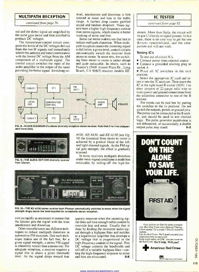
The comparator/control circuit com- pares the levels of the DC voltages derived from the two IF signals and immediately selects the antenna and tuner combination with the lowest DC voltage from the AM component of a multipath signal. The control circuit switches the input of the audio amplifier to the output of the tuner providing the better signal. Switching oc -
level, interference and distortion is first noticed as noise and hiss in the treble range. A further drop causes garbled sound and random dropouts. Mono sig- nals have a higher high -frequency content than stereo signals, which results in better masking of noise and hiss.
Some car stereo makers use that fact to reduce multipath distortion. When multi - path reception causes the incoming signal to fall below a given level, control circuits automatically switch the receiver from stereo to mono. In some sets, the switch- ing from stereo to mono is rather abrupt and quite noticeable. In others, such as Pioneer's (5000 Airport Plaza Dr. , Long Beach, CA 90815) receiver models KE-
ANT 1
ANT 2
TUNER 1
LOCAL OSC
TUNER 2
COMPARATOR CONTROL
IF
FM
DET1
SWITCH
FM
DET2
AUDIO AMP ElSPEAKER
FIG. 8-BLOCK DIAGRAM of a stereo diversity reception stereo receiver. Note that it has two indepen- dent front ends.
: ; :.. to .7.5 .
FIG. 9-THE AUDIA DXT-1000 diversity receiver from Clarion.
A630, KE-A430, and KE-A330 (see Fig. 10) the transition from stereo to mono is achieved by a gradual blend of the left - and right -channel signals. As the FM sig- nal gets stronger, the effect is gradually reversed.
In some receivers multipath distortion under weak -signal conditions is made less noticeable by rolling -off the high-fre-
FIG. 10-THE KE-A330 stereo receiver from Pioneer automatically switches to mono when the signal strength drops below the level required for acceptable stereo reception..
curs as rapidly as necessary to ensure that the listener gets the signal with the least interference and distortion.
Other manufacturers use different tech- niques to reduce multipath distortion in automotive FM receivers. One such tech- nique makes use of the fact that, for a given signal strength, a stereo FM signal is inherently noisier than a mono one. For adequate reception, a receiver requires a signal that is above a given threshold level. As the signal drops toward that
quency response when the incoming sig- nal does not have enough treble content to over -ride hiss and noise. Usually that is done by feeding the recovered audio sig- nal through a highpass filter and rectifier to a logarithmic amplifier that develops a DC voltage that is proportional to the high -frequency content of the signal. That DC voltage controls the bandwidth and roll -off of a variable highpass filter-cut- ting the high -frequency response so noise and hiss are eliminated. R -E
IC TESTER
continued from page 82
unison. More than likely, the circuit will tie pin 12 directly to signal ground. In that case, there is no easy way to get the two devices synchronized, and the com- parison test will not work.
Testing IC's To test out -of -circuit ICs: Connect power from external source Connect a grounded shorting plug to
socket A Place all IC switches in the OUT
position. Select the appropriate IC card and in-
sert it into the IC analyzer. Then insert the IC in the right-hand B socket (SO5). Use short jumpers of 22 -gauge solid wire to make power and ground connections from the solderless connector to one of the B sockets.
The inputs can be tied low by putting the switches to the IN position. Do not switch the outputs, power, or ground pins. The pulser can be connected at the B sock- et, and should be used to test clocked logic. The pulse generator pushbutton is not debounced, so occasionally a double output pulse may result. R -E
DON'T COUNT ON THIS ALONE
TO SAVE YOUR LIFE.
First -aid kits are fine for some emergen- cies. But what if you were choking? Having a heart attack? Or a stroke? This kit would be useless. Call the Red Cross. We'll teach you and your employees how to save a life. From work -safety to CPR, you can count on the Red Cross. We'll help. Will you? + American Red Cross
. 1.1C4 S..+w d The Nilwein
115
www.americanradiohistory.com