Embed Size (px)
Citation preview
The results refer only to the specimens above mentioned. This Test Report must always be copied entirely. Any copying of extracts and publication require the prior consent of the Laboratory.
Test Report No. P50-18-0403_1-en Environmental Tests
Order No.: 50-18-0403 This report includes Date: 20/12/2018 27 pages. Editor: Mr. Koch Documentation: kr phone: 03302 49982 58
Delivery date specimen: 10/09/2018
Test date: 12/09/2018 until 04/11/2018
Specimen: - 1 Ultrasonic wind sensor
- 1 ARCO-SERIAL combined wind sensor NMEA
- 1 PRO-WEA WG-SENSOR 4-20 mA, 0-60 m/s
- 1 PRO-WEA WR-SONSOR 4-20 mA,
- 1 PROFESSIONAL Sensor ice free IX 3.0 WR
- 1 PROFESSIONAL Sensor ice free IX 2.0 WG
- 1 INDUSRTY wind direction sensor
- 1 THP-NAV temp.-humid.-pressure-sensor in a sensor-protection housing
Specimens No. 50-18-0403-1..-8(a/b), for details see page 2
Relevant specification: Cold test Ad according to DIN EN 60068-2-1 (01/2008)
Condensation test CH according to ISO 6270-2 (09/2005) and based on DIN EN ISO 12944-6 (07/1998), category C4
Salt mist test based on DIN EN ISO 7253 (04/2002) and based on DIN EN ISO 12944-6 (07/1998), category C4
(for details see page 2)
Objective: Proof of the stability of the specimens at the conditions mentioned in the relevant specification.
Results: The specimens were tested according to the relevant specification. After the condensation test and salt mist test, signs of corrosion were visually detected at the surfaces of the specimens (stains on the surfaces, surface defects at the black anodized layer, white deposits, swollen seal and red rust), for details see page 7. Operability test after all exposures was done by the customer, see page
Andreas Litzba Head of the Environmental Lab
Customer: LAMBRECHT meteo GmbH Mrs. Molthan Friedländer Weg 65-67 37085 Göttingen
Page 2 of 27 to test report No. P50-18-0403_1-en
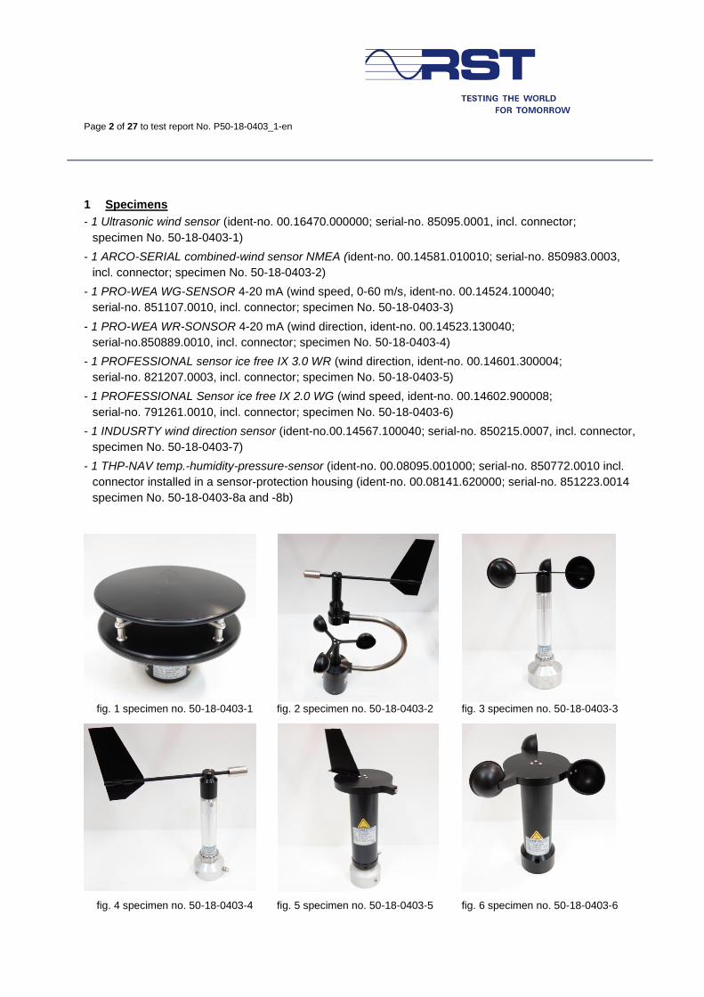
1 Specimens
- 1 Ultrasonic wind sensor (ident-no. 00.16470.000000; serial-no. 85095.0001, incl. connector;
specimen No. 50-18-0403-1)
- 1 ARCO-SERIAL combined-wind sensor NMEA (ident-no. 00.14581.010010; serial-no. 850983.0003,
incl. connector; specimen No. 50-18-0403-2)
- 1 PRO-WEA WG-SENSOR 4-20 mA (wind speed, 0-60 m/s, ident-no. 00.14524.100040;
serial-no. 851107.0010, incl. connector; specimen No. 50-18-0403-3)
- 1 PRO-WEA WR-SONSOR 4-20 mA (wind direction, ident-no. 00.14523.130040;
serial-no.850889.0010, incl. connector; specimen No. 50-18-0403-4)
- 1 PROFESSIONAL sensor ice free IX 3.0 WR (wind direction, ident-no. 00.14601.300004;
serial-no. 821207.0003, incl. connector; specimen No. 50-18-0403-5)
- 1 PROFESSIONAL Sensor ice free IX 2.0 WG (wind speed, ident-no. 00.14602.900008;
serial-no. 791261.0010, incl. connector; specimen No. 50-18-0403-6)
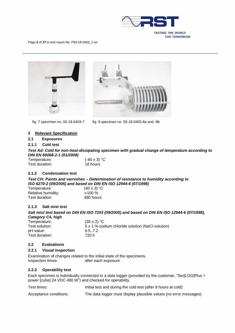
- 1 INDUSRTY wind direction sensor (ident-no.00.14567.100040; serial-no. 850215.0007, incl. connector,
specimen No. 50-18-0403-7)
- 1 THP-NAV temp.-humidity-pressure-sensor (ident-no. 00.08095.001000; serial-no. 850772.0010 incl.
connector installed in a sensor-protection housing (ident-no. 00.08141.620000; serial-no. 851223.0014
specimen No. 50-18-0403-8a and -8b)
fig. 1 specimen no. 50-18-0403-1 fig. 2 specimen no. 50-18-0403-2 fig. 3 specimen no. 50-18-0403-3
fig. 4 specimen no. 50-18-0403-4 fig. 5 specimen no. 50-18-0403-5 fig. 6 specimen no. 50-18-0403-6
Page 3 of 27 to test report No. P50-18-0403_1-en
fig. 7 specimen no. 50-18-0403-7 fig. 8 specimen no. 50-18-0403-8a and -8b
2 Relevant Specification
2.1 Exposures
2.1.1 Cold test
Test Ad: Cold for non-heat-dissipating specimen with gradual change of temperature according to DIN EN 60068-2-1 (01/2008) Temperature: (-40 ± 3) °C Test duration: 16 hours
2.1.2 Condensation test
Test CH: Paints and varnishes – Determination of resistance to humidity according to ISO 6270-2 (09/2005) and based on DIN EN ISO 12944-6 (07/1998) Temperature: (40 ± 3) °C
Relative humidity: ≈100 % Test duration: 480 hours
2.1.3 Salt mist test
Salt mist test based on DIN EN ISO 7253 (09/2005) and based on DIN EN ISO 12944-6 (07/1998), Category C4, high Temperature: (35 ± 2) °C Test solution: 5 ± 1 % sodium chloride solution (NaCl-solution) pH-value: 6.5..7.2 Test duration: 720 h
2.2 Evaluations
2.2.1 Visual inspection
Examination of changes related to the initial state of the specimens. Inspection times: after each exposure
2.2.2 Operability test
Each specimen is individually connected to a data logger (provided by the customer, “Ser[LOG]Plus + power [cube] 24 VDC 480 W”) and checked for operability.
Test times: Initial test and during the cold test (after 8 hours at cold)
Acceptance conditions: The data logger must display plausible values (no error messages)
Page 4 of 27 to test report No. P50-18-0403_1-en
3 Test procedure
3.1 Test equipment
The test and measuring instruments as well as the calibration status were checked before using.
Test and measuring equipment Inv. No.
Climate test chamber type C-70/1000, Manufacturer CTS GmbH M574355
Salt mist test chamber type HSA 400, Manufacturer Vötsch M566579
Refractometer type HI-96821 Manufacturer ATP Messtechnik M563459
Precision balance type MB200 M564827
3.2 Test sequence
The tests were carried out in the following sequence:
Pos. Exposure
1. Operability test (initial test)
2. Cold test, 16 hours (operability test after the first 8 h)
3. Condensation test, CH 480 h
4. Salt mist test 720 h
3.3 Test setup
The test setups of the climate and corrosion tests are shown in the following figures.
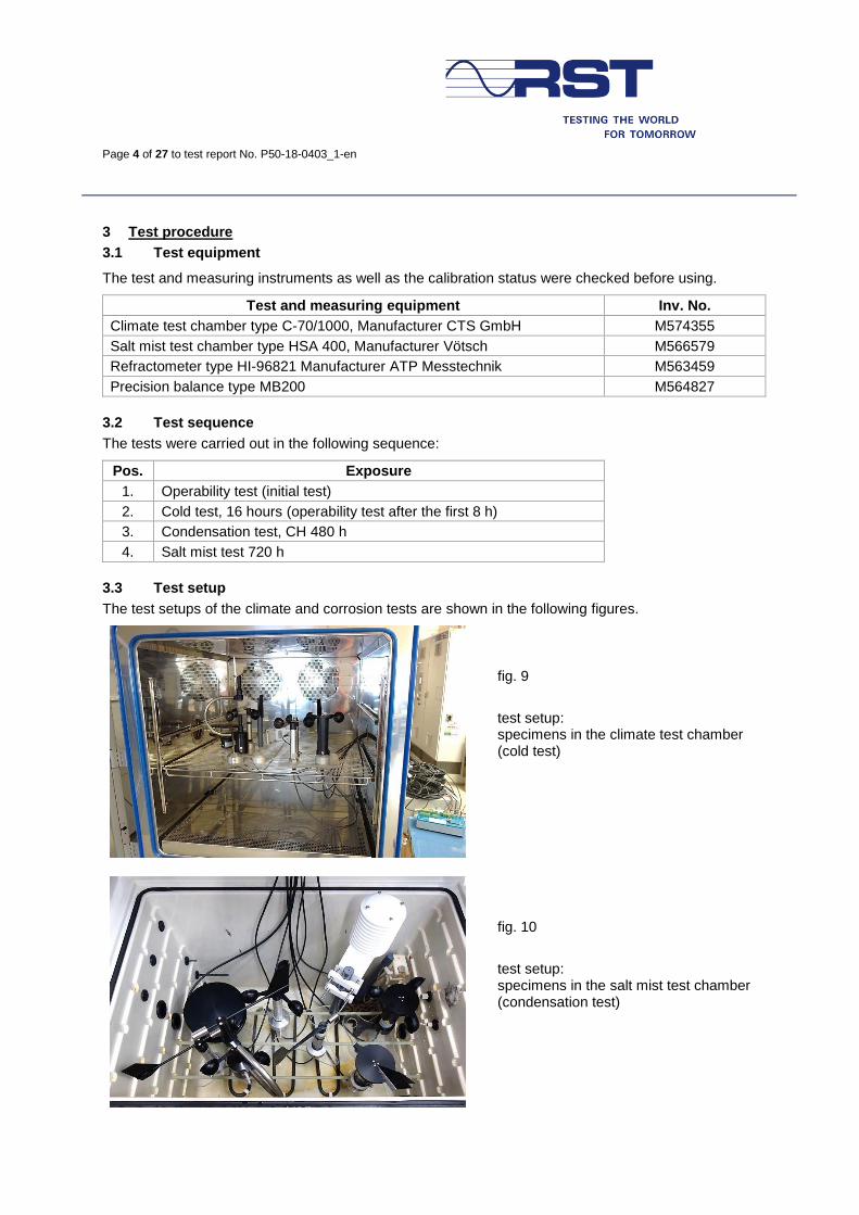
fig. 9
test setup: specimens in the climate test chamber (cold test)
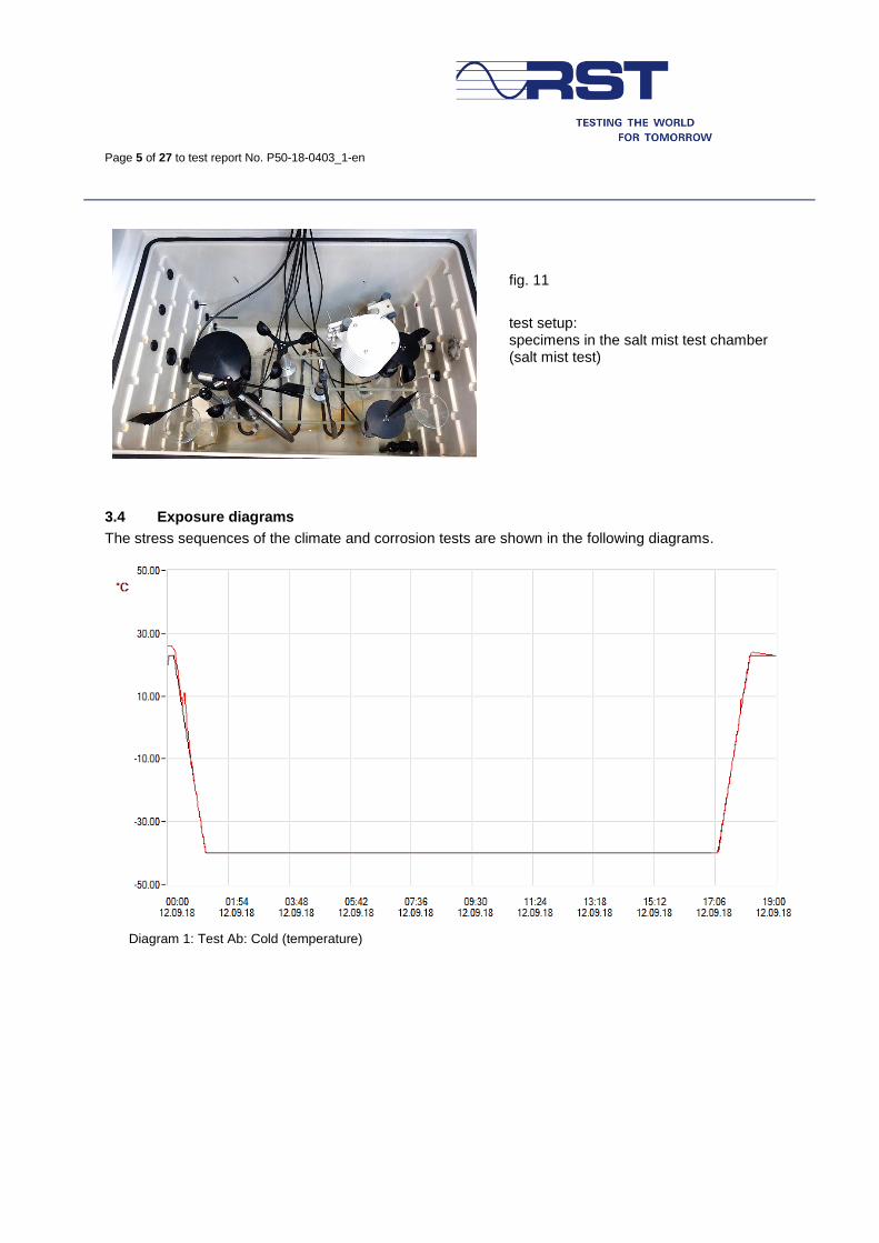
fig. 10
test setup: specimens in the salt mist test chamber (condensation test)
Page 5 of 27 to test report No. P50-18-0403_1-en
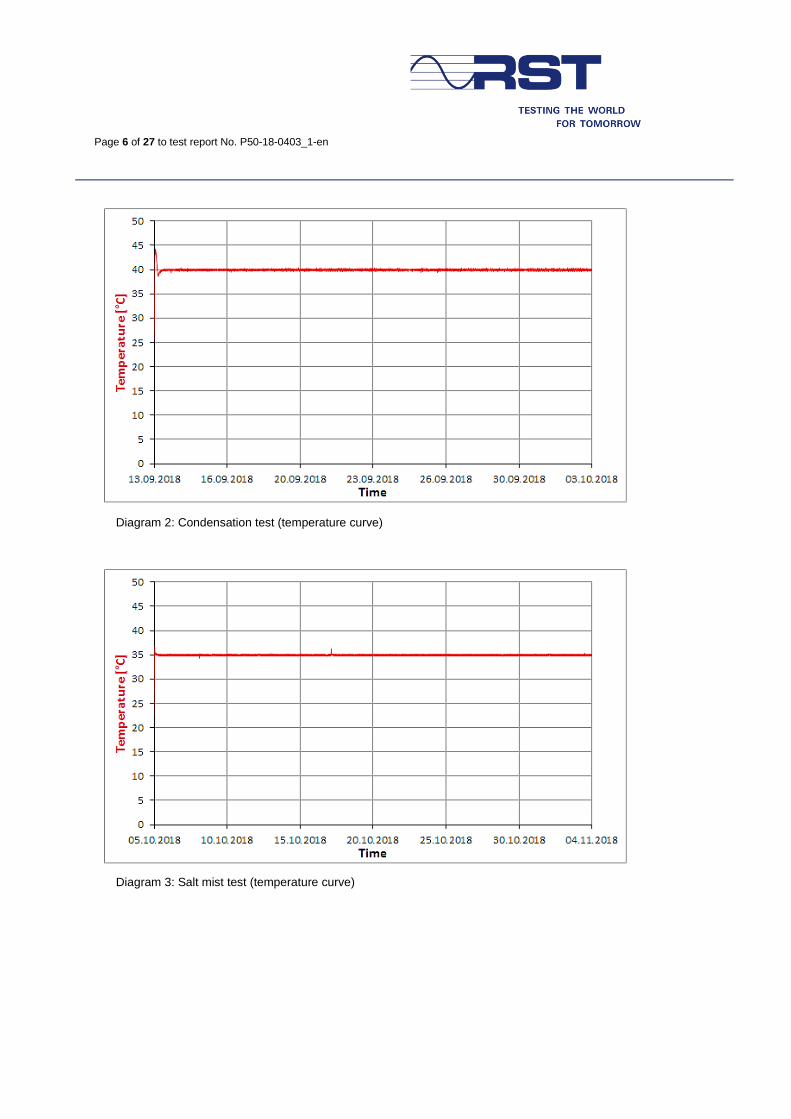
fig. 11
test setup: specimens in the salt mist test chamber (salt mist test)
3.4 Exposure diagrams
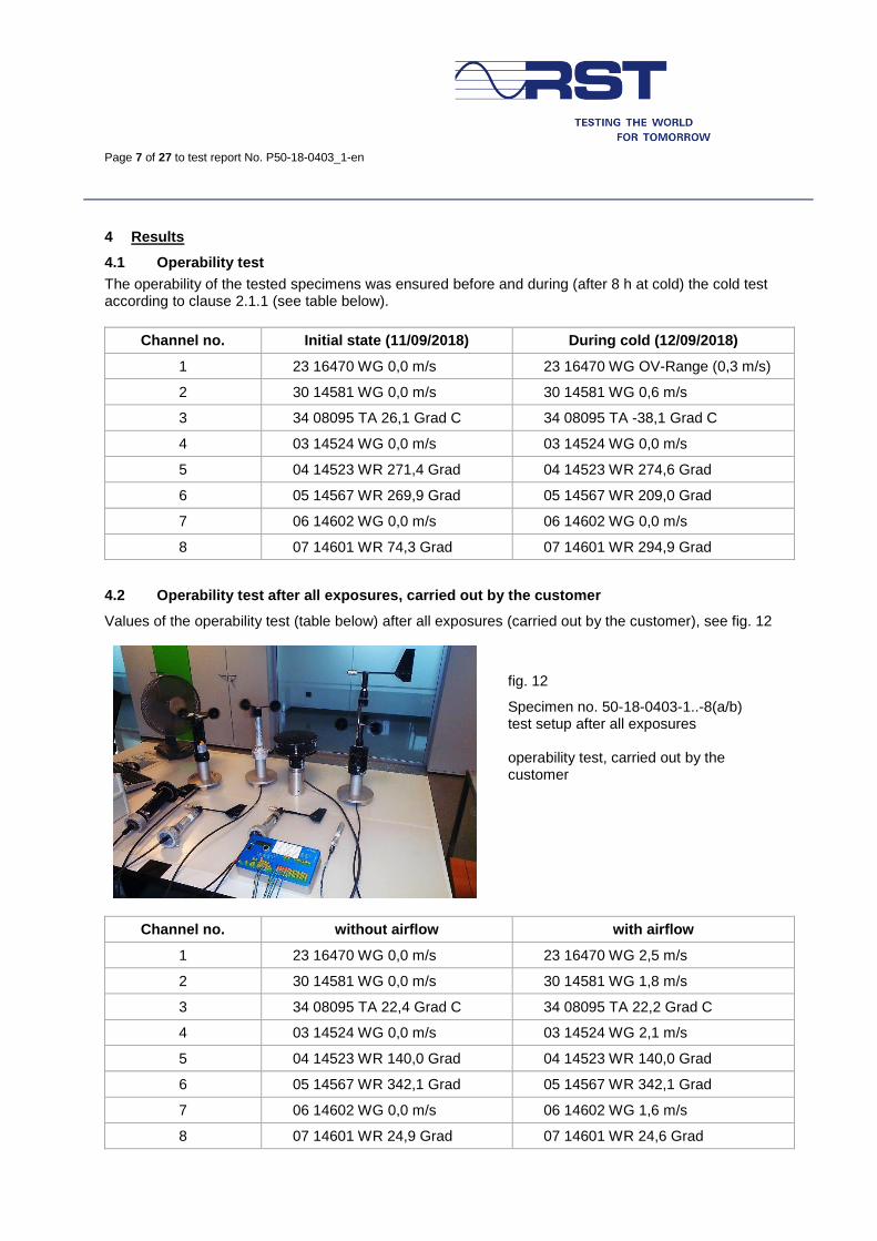
The stress sequences of the climate and corrosion tests are shown in the following diagrams.
Diagram 1: Test Ab: Cold (temperature)
Page 6 of 27 to test report No. P50-18-0403_1-en
Diagram 2: Condensation test (temperature curve)
Diagram 3: Salt mist test (temperature curve)
Page 7 of 27 to test report No. P50-18-0403_1-en
4 Results
4.1 Operability test
The operability of the tested specimens was ensured before and during (after 8 h at cold) the cold test according to clause 2.1.1 (see table below).
Channel no. Initial state (11/09/2018) During cold (12/09/2018)
1 23 16470 WG 0,0 m/s 23 16470 WG OV-Range (0,3 m/s)
2 30 14581 WG 0,0 m/s 30 14581 WG 0,6 m/s
3 34 08095 TA 26,1 Grad C 34 08095 TA -38,1 Grad C
4 03 14524 WG 0,0 m/s 03 14524 WG 0,0 m/s
5 04 14523 WR 271,4 Grad 04 14523 WR 274,6 Grad
6 05 14567 WR 269,9 Grad 05 14567 WR 209,0 Grad
7 06 14602 WG 0,0 m/s 06 14602 WG 0,0 m/s
8 07 14601 WR 74,3 Grad 07 14601 WR 294,9 Grad
4.2 Operability test after all exposures, carried out by the customer
Values of the operability test (table below) after all exposures (carried out by the customer), see fig. 12
fig. 12
Specimen no. 50-18-0403-1..-8(a/b) test setup after all exposures operability test, carried out by the customer
Channel no. without airflow with airflow
1 23 16470 WG 0,0 m/s 23 16470 WG 2,5 m/s
2 30 14581 WG 0,0 m/s 30 14581 WG 1,8 m/s
3 34 08095 TA 22,4 Grad C 34 08095 TA 22,2 Grad C
4 03 14524 WG 0,0 m/s 03 14524 WG 2,1 m/s
5 04 14523 WR 140,0 Grad 04 14523 WR 140,0 Grad
6 05 14567 WR 342,1 Grad 05 14567 WR 342,1 Grad
7 06 14602 WG 0,0 m/s 06 14602 WG 1,6 m/s
8 07 14601 WR 24,9 Grad 07 14601 WR 24,6 Grad
Page 8 of 27 to test report No. P50-18-0403_1-en
4.3 Visual inspection
Test time Result
16 h Cold No changes compared to the initial state of the specimens were visually detected
480 h Condensation
- Stains at the surfaces - Surface defects at the black anodized layer - White deposits / signs of corrosion - Swollen seal
See fig. 13 to fig. 41
720 h Salt mist
- Stains at the surfaces - Surface defects at the black anodized layer - White deposits / signs of corrosion - Swollen seal - Red rust
See fig. 42..fig. 71
4.4 Photographic representation of the results
4.4.1 After the condensation test
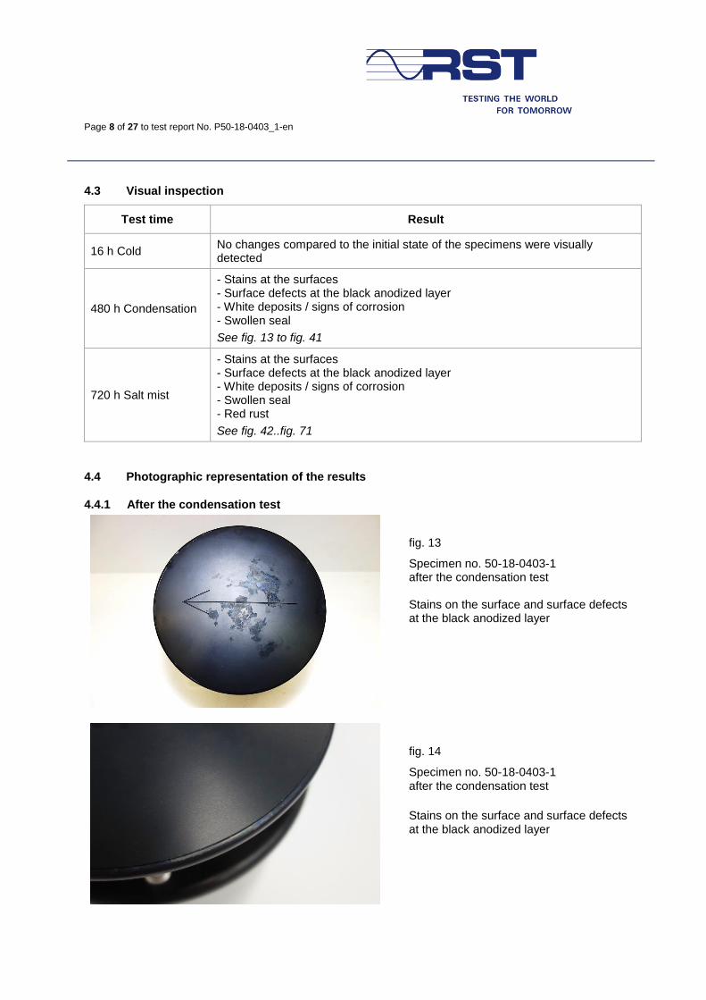
fig. 13
Specimen no. 50-18-0403-1 after the condensation test Stains on the surface and surface defects at the black anodized layer
fig. 14
Specimen no. 50-18-0403-1 after the condensation test
Stains on the surface and surface defects at the black anodized layer
Page 9 of 27 to test report No. P50-18-0403_1-en
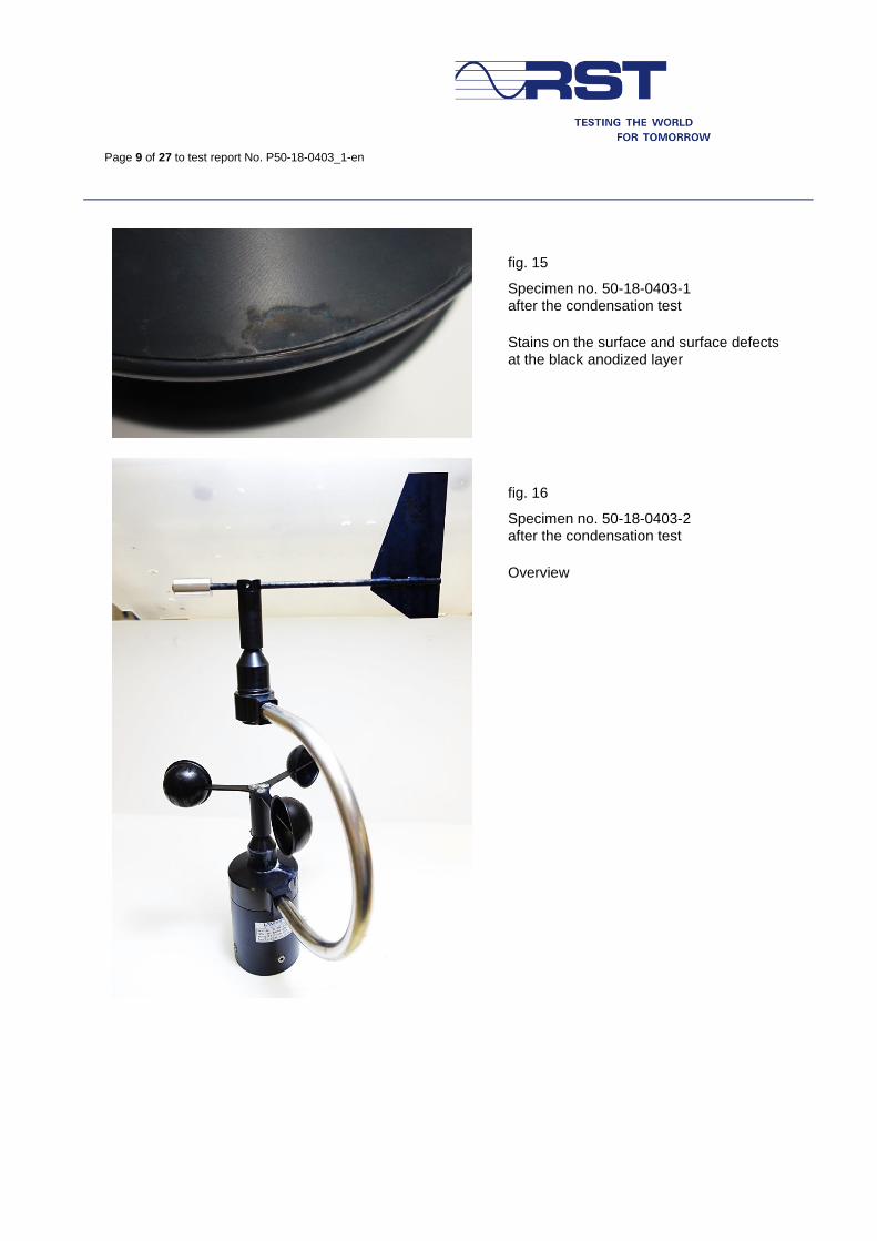
fig. 15
Specimen no. 50-18-0403-1 after the condensation test
Stains on the surface and surface defects at the black anodized layer
fig. 16
Specimen no. 50-18-0403-2 after the condensation test
Overview
Page 10 of 27 to test report No. P50-18-0403_1-en
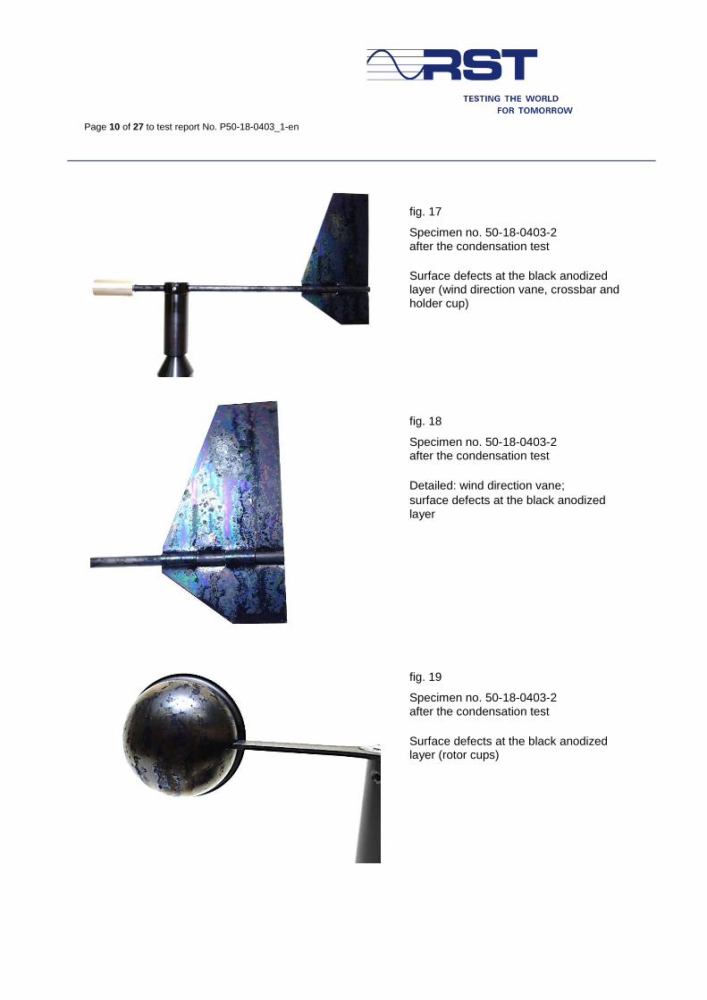
fig. 17
Specimen no. 50-18-0403-2 after the condensation test
Surface defects at the black anodized layer (wind direction vane, crossbar and holder cup)
fig. 18
Specimen no. 50-18-0403-2 after the condensation test
Detailed: wind direction vane;
surface defects at the black anodized layer
fig. 19
Specimen no. 50-18-0403-2 after the condensation test
Surface defects at the black anodized layer (rotor cups)
Page 11 of 27 to test report No. P50-18-0403_1-en
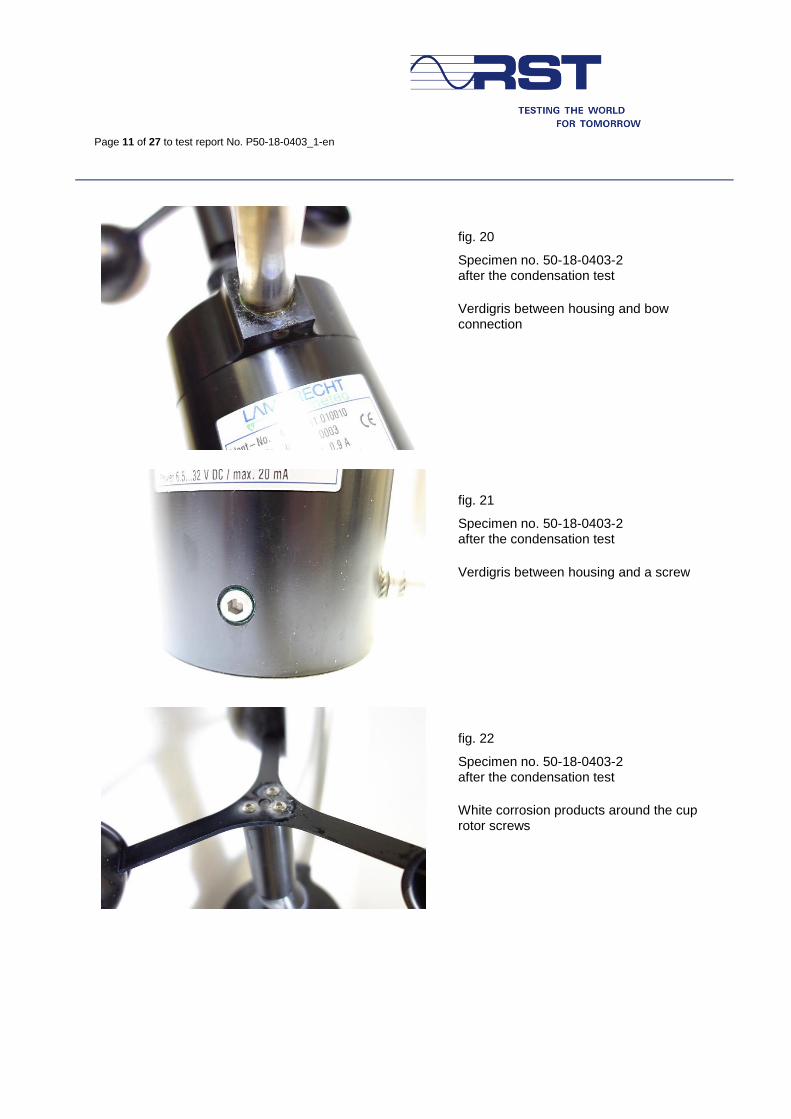
fig. 20
Specimen no. 50-18-0403-2 after the condensation test
Verdigris between housing and bow connection
fig. 21
Specimen no. 50-18-0403-2 after the condensation test
Verdigris between housing and a screw
fig. 22
Specimen no. 50-18-0403-2 after the condensation test
White corrosion products around the cup rotor screws
Page 12 of 27 to test report No. P50-18-0403_1-en
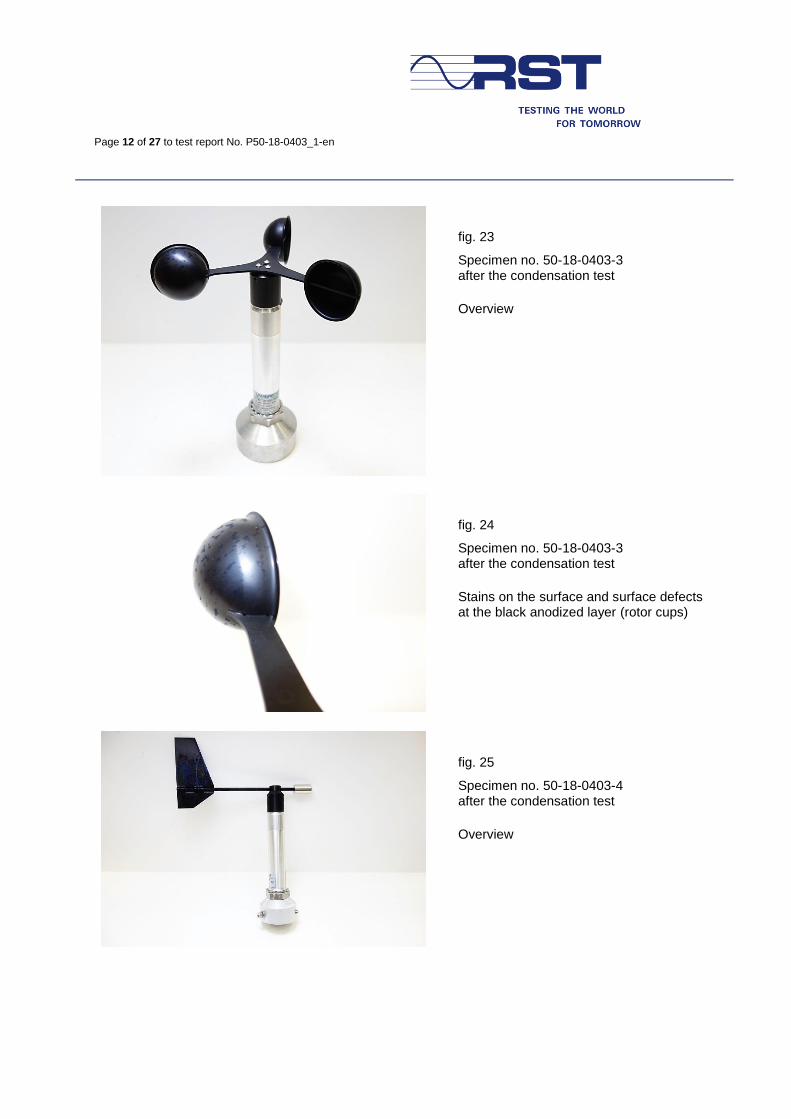
fig. 23
Specimen no. 50-18-0403-3 after the condensation test
Overview
fig. 24
Specimen no. 50-18-0403-3 after the condensation test
Stains on the surface and surface defects at the black anodized layer (rotor cups)
fig. 25
Specimen no. 50-18-0403-4 after the condensation test
Overview
Page 13 of 27 to test report No. P50-18-0403_1-en
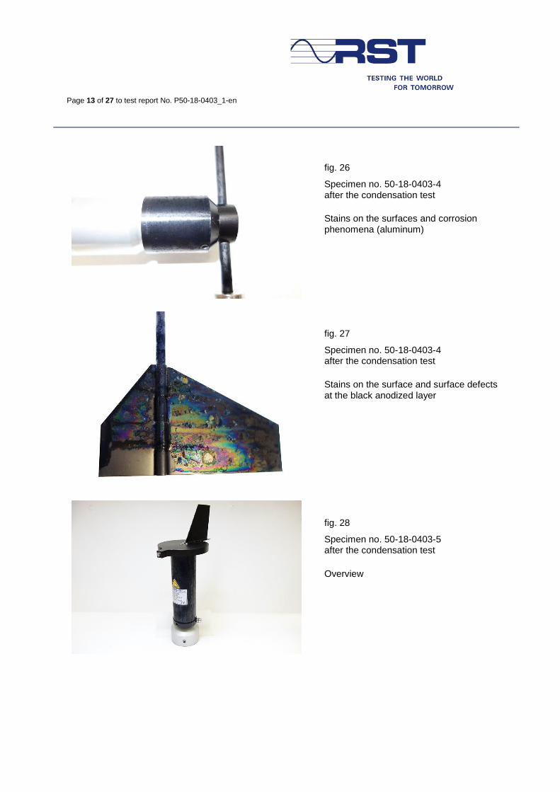
fig. 26
Specimen no. 50-18-0403-4 after the condensation test
Stains on the surfaces and corrosion phenomena (aluminum)
fig. 27
Specimen no. 50-18-0403-4 after the condensation test
Stains on the surface and surface defects at the black anodized layer
fig. 28
Specimen no. 50-18-0403-5 after the condensation test
Overview
Page 14 of 27 to test report No. P50-18-0403_1-en
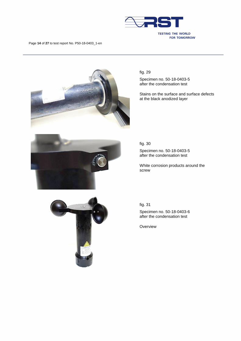
fig. 29
Specimen no. 50-18-0403-5 after the condensation test
Stains on the surface and surface defects at the black anodized layer
fig. 30
Specimen no. 50-18-0403-5 after the condensation test
White corrosion products around the screw
fig. 31
Specimen no. 50-18-0403-6 after the condensation test
Overview
Page 15 of 27 to test report No. P50-18-0403_1-en
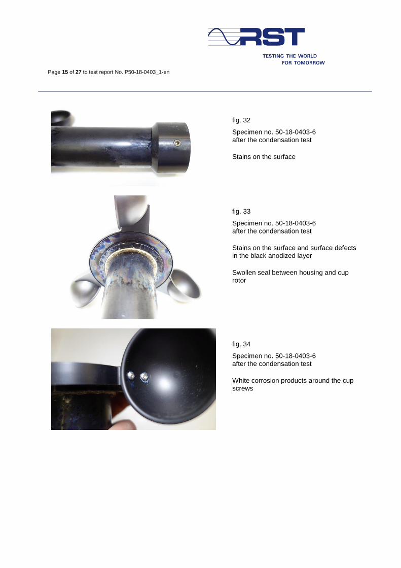
fig. 32
Specimen no. 50-18-0403-6 after the condensation test
Stains on the surface
fig. 33
Specimen no. 50-18-0403-6 after the condensation test
Stains on the surface and surface defects in the black anodized layer
Swollen seal between housing and cup rotor
fig. 34
Specimen no. 50-18-0403-6 after the condensation test
White corrosion products around the cup screws
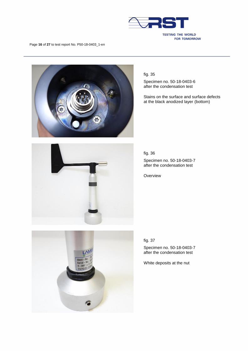
Page 16 of 27 to test report No. P50-18-0403_1-en
fig. 35
Specimen no. 50-18-0403-6 after the condensation test
Stains on the surface and surface defects at the black anodized layer (bottom)
fig. 36
Specimen no. 50-18-0403-7 after the condensation test
Overview
fig. 37
Specimen no. 50-18-0403-7 after the condensation test
White deposits at the nut
Page 17 of 27 to test report No. P50-18-0403_1-en
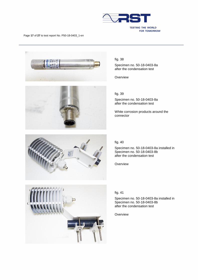
fig. 38
Specimen no. 50-18-0403-8a after the condensation test
Overview
fig. 39
Specimen no. 50-18-0403-8a after the condensation test
White corrosion products around the connector
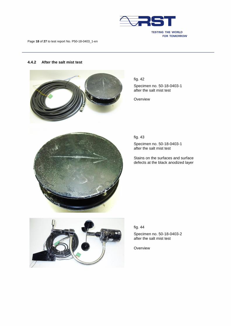
fig. 40
Specimen no. 50-18-0403-8a installed in Specimen no. 50-18-0403-8b after the condensation test
Overview
fig. 41
Specimen no. 50-18-0403-8a installed in Specimen no. 50-18-0403-8b after the condensation test
Overview
Page 18 of 27 to test report No. P50-18-0403_1-en
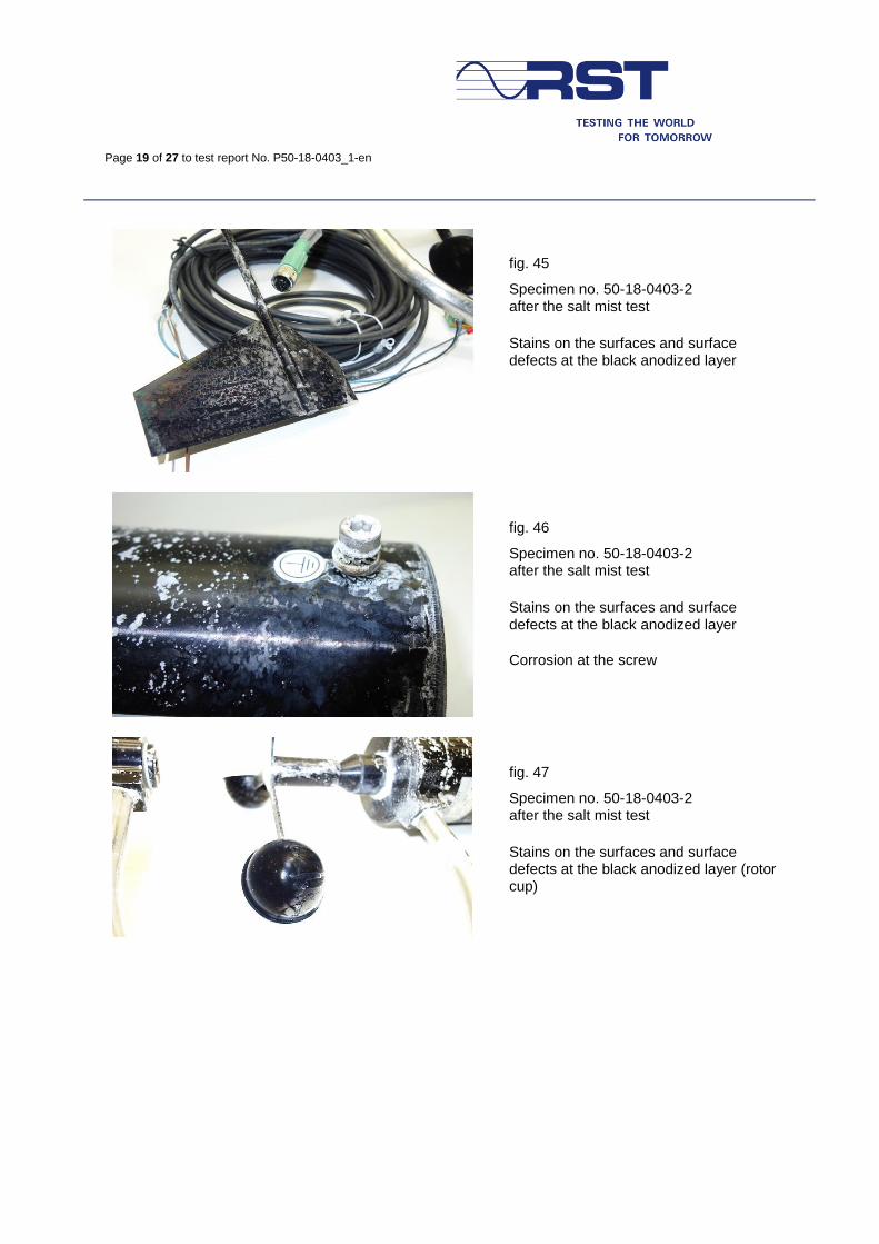
4.4.2 After the salt mist test
fig. 42
Specimen no. 50-18-0403-1 after the salt mist test Overview
fig. 43
Specimen no. 50-18-0403-1 after the salt mist test
Stains on the surfaces and surface defects at the black anodized layer
fig. 44
Specimen no. 50-18-0403-2 after the salt mist test
Overview
Page 19 of 27 to test report No. P50-18-0403_1-en
fig. 45
Specimen no. 50-18-0403-2 after the salt mist test
Stains on the surfaces and surface defects at the black anodized layer
fig. 46
Specimen no. 50-18-0403-2 after the salt mist test
Stains on the surfaces and surface defects at the black anodized layer
Corrosion at the screw
fig. 47
Specimen no. 50-18-0403-2 after the salt mist test
Stains on the surfaces and surface defects at the black anodized layer (rotor cup)
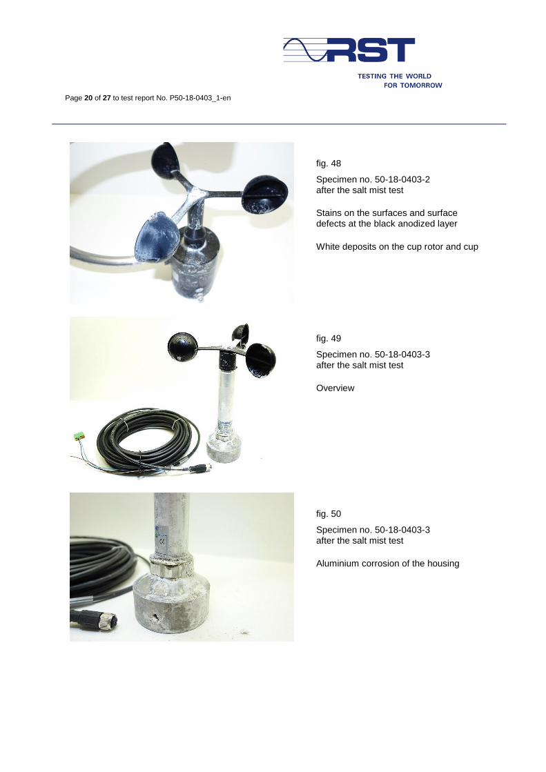
Page 20 of 27 to test report No. P50-18-0403_1-en
fig. 48
Specimen no. 50-18-0403-2 after the salt mist test
Stains on the surfaces and surface defects at the black anodized layer
White deposits on the cup rotor and cup
fig. 49
Specimen no. 50-18-0403-3 after the salt mist test
Overview
fig. 50
Specimen no. 50-18-0403-3 after the salt mist test
Aluminium corrosion of the housing
Page 21 of 27 to test report No. P50-18-0403_1-en
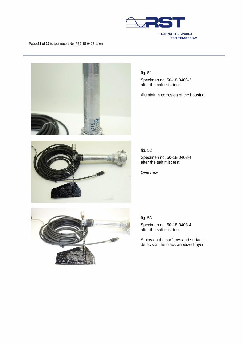
fig. 51
Specimen no. 50-18-0403-3 after the salt mist test
Aluminium corrosion of the housing
fig. 52
Specimen no. 50-18-0403-4 after the salt mist test
Overview
fig. 53
Specimen no. 50-18-0403-4 after the salt mist test
Stains on the surfaces and surface defects at the black anodized layer
Page 22 of 27 to test report No. P50-18-0403_1-en
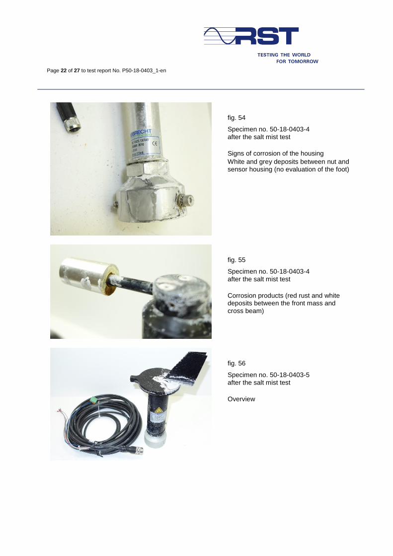
fig. 54
Specimen no. 50-18-0403-4 after the salt mist test
Signs of corrosion of the housing
White and grey deposits between nut and sensor housing (no evaluation of the foot)
fig. 55
Specimen no. 50-18-0403-4 after the salt mist test
Corrosion products (red rust and white deposits between the front mass and cross beam)
fig. 56
Specimen no. 50-18-0403-5 after the salt mist test
Overview
Page 23 of 27 to test report No. P50-18-0403_1-en
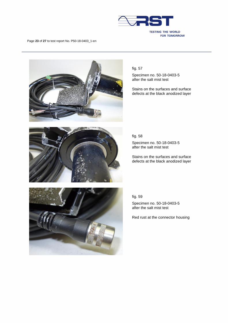
fig. 57
Specimen no. 50-18-0403-5 after the salt mist test
Stains on the surfaces and surface defects at the black anodized layer
fig. 58
Specimen no. 50-18-0403-5 after the salt mist test
Stains on the surfaces and surface defects at the black anodized layer
fig. 59
Specimen no. 50-18-0403-5 after the salt mist test
Red rust at the connector housing
Page 24 of 27 to test report No. P50-18-0403_1-en
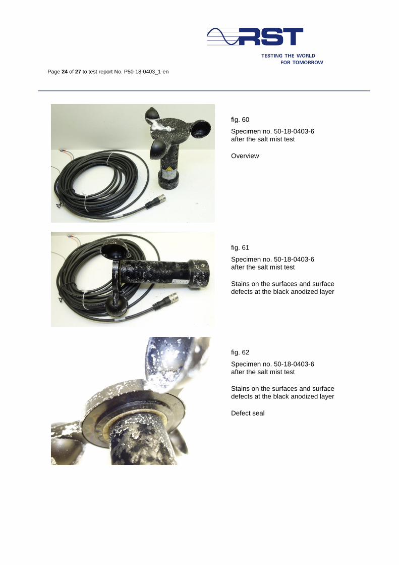
fig. 60
Specimen no. 50-18-0403-6 after the salt mist test
Overview
fig. 61
Specimen no. 50-18-0403-6 after the salt mist test
Stains on the surfaces and surface defects at the black anodized layer
fig. 62
Specimen no. 50-18-0403-6 after the salt mist test
Stains on the surfaces and surface defects at the black anodized layer
Defect seal
Page 25 of 27 to test report No. P50-18-0403_1-en
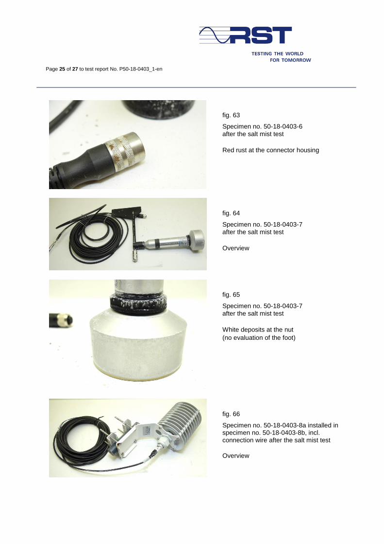
fig. 63
Specimen no. 50-18-0403-6 after the salt mist test
Red rust at the connector housing
fig. 64
Specimen no. 50-18-0403-7 after the salt mist test
Overview
fig. 65
Specimen no. 50-18-0403-7 after the salt mist test
White deposits at the nut
(no evaluation of the foot)
fig. 66
Specimen no. 50-18-0403-8a installed in specimen no. 50-18-0403-8b, incl. connection wire after the salt mist test
Overview
Page 26 of 27 to test report No. P50-18-0403_1-en
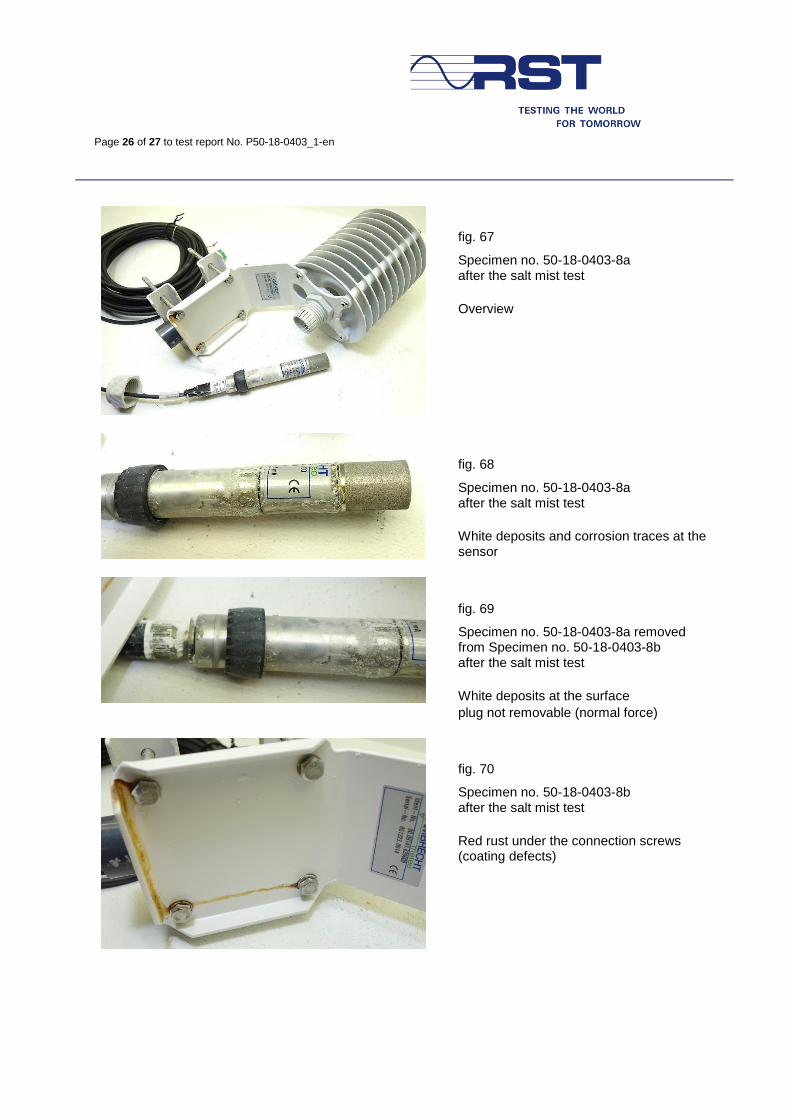
fig. 67
Specimen no. 50-18-0403-8a after the salt mist test
Overview
fig. 68
Specimen no. 50-18-0403-8a after the salt mist test
White deposits and corrosion traces at the sensor
fig. 69
Specimen no. 50-18-0403-8a removed from Specimen no. 50-18-0403-8b after the salt mist test
White deposits at the surface
plug not removable (normal force)
fig. 70
Specimen no. 50-18-0403-8b after the salt mist test
Red rust under the connection screws (coating defects)
Page 27 of 27 to test report No. P50-18-0403_1-en
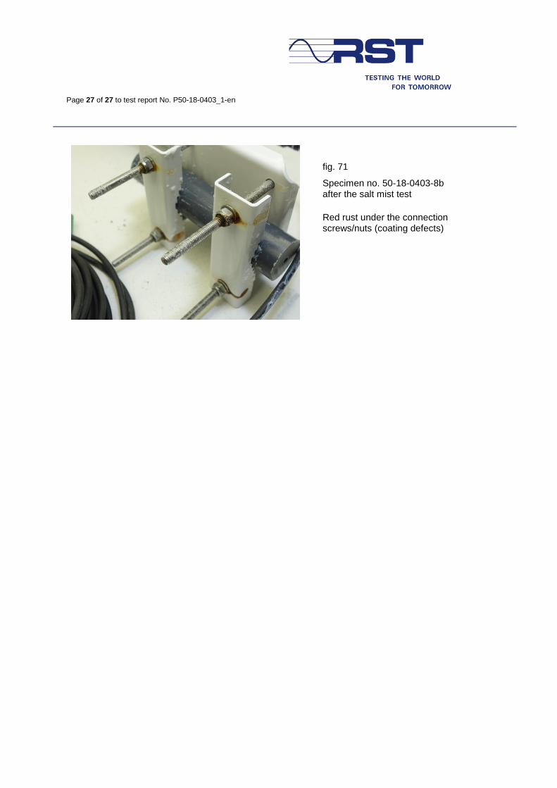
fig. 71
Specimen no. 50-18-0403-8b after the salt mist test
Red rust under the connection screws/nuts (coating defects)