Embed Size (px)
Citation preview
TEST REPORT IEC 60884-1
Plugs and socket-outlets for household and similar purposes Part 1: General requirements
Report Reference No. .................... : SH12030248-001
Date of issue .................................... : 2012-04-28
Total number of pages 46
Testing Laboratory......................... : INTERTEK TESTING SERVICES Shanghai
Address ............................................ : Building No.86, 1198 Qinzhou Road (North), Shanghai 200233, China
Applicant’s name............................ : Ningbo Linsheng Electric Co., Ltd.
Address ............................................ : Xiaodong Industrial Zone, Yuyao, Zhejiang, China/315409 Test specification:
Standard ........................................... : IEC 60884-1:2002 (Third Edition) + A1:2006;
SANS 164-0:2007 + SANS 164-1:2007
Test procedure ................................. : Testing
Non-standard test method…………..: N/A Test Report Form No...................... : IEC60884_1C
Test Report Form(s) Originator ........ : IMQ
Master TRF ...................................... : Dated 2006-10
Copyright © 2006 IEC System for Conformity Testing and Certification of Electrical Equipment (IECEE), Geneva, Switzerland. All rights reserved.
This publication may be reproduced in whole or in part for non-commercial purposes as long as the IECEE is acknowledged as copyright owner and source of the material. IECEE takes no responsibility for and will not assume liability for damages resulting from the reader's interpretation of the reproduced material due to its placement and context.
If this Test Report Form is used by non-IECEE members, the IECEE/IEC logo and the reference to the CB Scheme procedure shall be removed.
This report is not valid as a CB Test Report unless signed by an approved CB Testing Laboratory and appended to a CB Test Certificate issued by an NCB in accordance with IECEE 02. Test item description .....................: South Africa Plug, non-rewirable
Trade Mark ....................................... :
Manufacturer .................................... : Same as the applicant
Model/Type reference ...................... : LA151A, LA151B
Ratings ............................................. : 16A, 250V~
Page 2 of 46 Report No.: SH12030248-001
Testing procedure and testing location:
k8l Testing Laboratory:
Testing location/ address ....................... : Associated CB Test Laboratory:
Testing location/ address ....................... :
Tested by (name+ signature) ......:
Approved by (name + signature).:
INTERTEK TESTING SERVICES Shanghai
Building No.86, 1198 Qinzhou Road (North), Shanghai 200233, China
Mathew Shen ... ···········
Testing procedure: TMP Tested by (name+ signature) ...... : ................................................... Approved by (name + signature) .: ...................................................
Testing location/ address ....................... :
Testing procedure: WMT Tested by (name+ signature) ......: .................................................. , Witnessed by (name + signature): ................................................... Approved by (name + signature).: ...................................................
Testing location/ address ....................... :
Testing procedure: SMT Tested by (name+ signature) ...... : ................................................... Approved by (name + signature).: ' '.........................'........' .' ............ Supervised by (name+ signature): ...................................................
Testing location/ address ....................... :
Testing procedure: RMT Tested by (name+ signature) ......: ................................................... Approved by (name + signature).: ................................................... Supervised by (name+ signature): ......,............................................
Testing location/ address ....................... :
TRF No.IEC60884_1C South Africa Power Cord Set Manufacturer www.yunhuanelectric.com
Page 3 of 47 Report No.: SH12030248-001
Summary of testing:
Tests performed (name of test and test clause): This test report complies with IEC 60884-1:2002 (Third Edition) + A1:2006 + SANS 164-0:2007+ SANS 164-1:2007
Testing location: Intertek Testing Services Shanghai
Summary of compliance with National Differences:
This test report complies with IEC 60884-1:2002 (Third Edition) + A1:2006 + SANS 164-0:2007+ SANS 164- 1:2007.
Factory information:
Ningbo Linsheng Electric Co., Ltd.
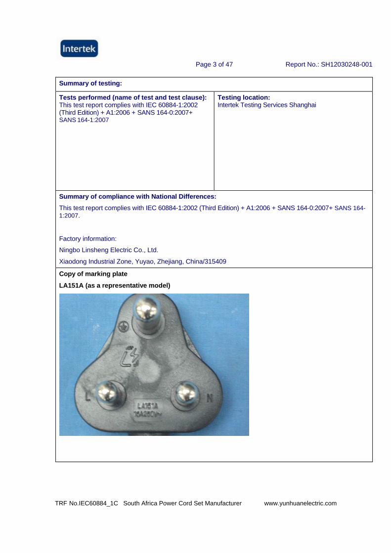
Xiaodong Industrial Zone, Yuyao, Zhejiang, China/315409 Copy of marking plate
LA151A (as a representative model)
TRF No.IEC60884_1C South Africa Power Cord Set Manufacturer www.yunhuanelectric.com
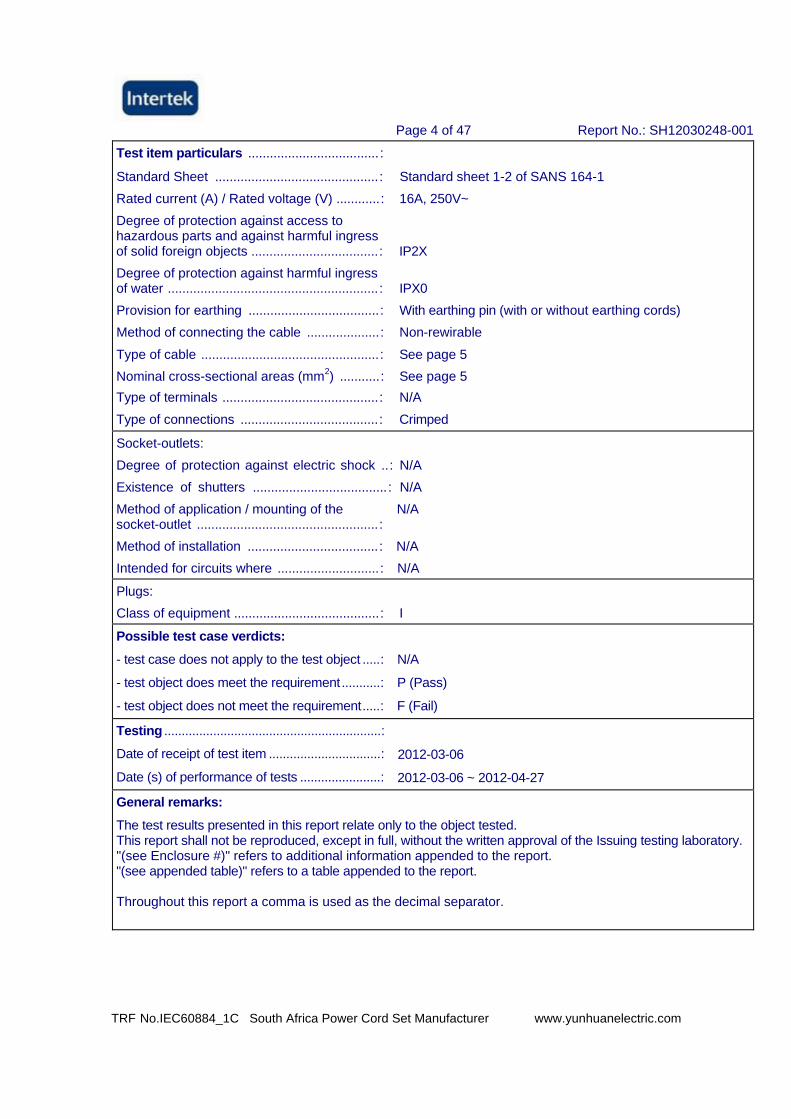
Page 4 of 47 Report No.: SH12030248-001
Test item particulars .................................... :
Standard Sheet .............................................: Standard sheet 1-2 of SANS 164-1 Rated current (A) / Rated voltage (V) ............: 16A, 250V~ Degree of protection against access to hazardous parts and against harmful ingress of solid foreign objects ...................................: IP2X
Degree of protection against harmful ingress of water ..........................................................: IPX0
Provision for earthing ....................................: With earthing pin (with or without earthing cords) Method of connecting the cable ....................: Non-rewirable
Type of cable .................................................: See page 5 Nominal cross-sectional areas (mm2) ...........: See page 5 Type of terminals ...........................................: N/A Type of connections ......................................: Crimped Socket-outlets: Degree of protection against electric shock ..: N/A Existence of shutters .....................................: N/A Method of application / mounting of the N/A socket-outlet ..................................................:
Method of installation ....................................: N/A
Intended for circuits where ............................: N/A Plugs:
Class of equipment ........................................: I Possible test case verdicts:
- test case does not apply to the test object .....: N/A
- test object does meet the requirement ...........: P (Pass)
- test object does not meet the requirement.....: F (Fail) Testing ..............................................................:
Date of receipt of test item ................................: 2012-03-06
Date (s) of performance of tests .......................: 2012-03-06 ~ 2012-04-27 General remarks:
The test results presented in this report relate only to the object tested. This report shall not be reproduced, except in full, without the written approval of the Issuing testing laboratory. "(see Enclosure #)" refers to additional information appended to the report. "(see appended table)" refers to a table appended to the report.
Throughout this report a comma is used as the decimal separator.
TRF No.IEC60884_1C South Africa Power Cord Set Manufacturer www.yunhuanelectric.com
Page 5 of 47 Report No.: SH12030248-001
General product information:
16A 250V~, IP20, Class I, non-rewirable, comply with Standard sheet 1-2 of SANS 164-1, with non-solid pin with or without insulating sleeves, with or without earthing cords for earthing pin, with lateral cord entry, with flexible cable as listed below. LA151A: with non-solid pin without insulating sleeves; LA151B: with non-solid pin with insulating sleeves
Remarks:
1. The samples for each group of testing were selected randomly from the samples provided by the manufacturer.
2. The test results reported in this test report shall refer only to the sample actually tested and shall not refer or be deemed to refer to bulk from which such a sample may be said to have been obtained.
3. Determination of the test result includes consideration of measurement uncertainty from the test equipment and methods.
4. We conclude that the product(s) presented in this test report complies (comply) with the standard according to the test results on the submitted samples.
Components certified:
HD type
Manufacturer
Nominal cross- sectional area
IEC type
Remarks
H05VV-F NINGBO LINSHENG ELECTRIC
CO.,LTD.
2x0,75mm2 HD21.5 (227 IEC 53)
VDE: 134675
H05VV-F NINGBO LINSHENG ELECTRIC
CO.,LTD.
3G0,75-1,5mm2 HD21.5 (227 IEC 53)
VDE: 134675
Material Declaration:
Main Parts Type Ingredient Manufacturer / Trade name Enclosure
P701
PVC
NINGBO LINSHENG ELECTRIC CO.,LTD.
Live part carrier 4306G
30
PBT
CiXi Yinsheng Electronic Components Factory
TRF No. IEC60884_1C
Page 6 of 47 Report No.: SH12030248-001
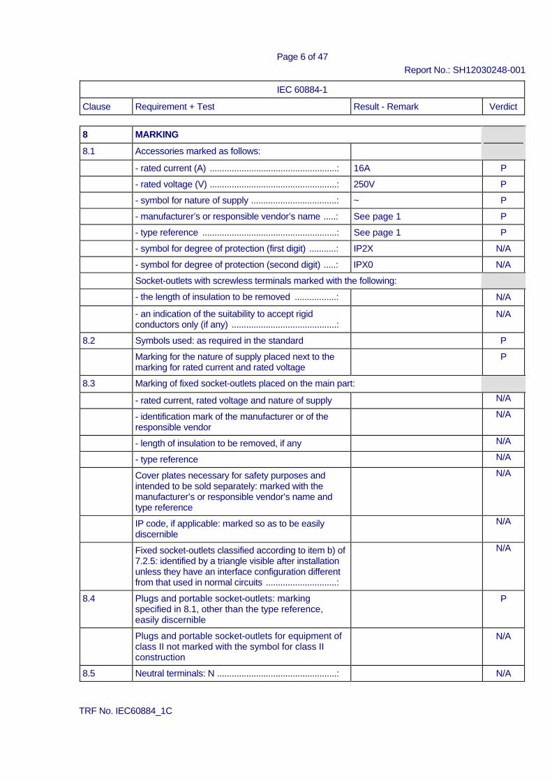
IEC 60884-1 Clause Requirement + Test Result - Remark Verdict
8 MARKING 8.1 Accessories marked as follows: - rated current (A) ....................................................: 16A P - rated voltage (V) ....................................................: 250V P - symbol for nature of supply ...................................: ~ P - manufacturer’s or responsible vendor’s name .....: See page 1 P - type reference .......................................................: See page 1 P - symbol for degree of protection (first digit) ...........: IP2X N/A - symbol for degree of protection (second digit) .....: IPX0 N/A Socket-outlets with screwless terminals marked with the following: - the length of insulation to be removed .................: N/A - an indication of the suitability to accept rigid
conductors only (if any) ...........................................: N/A
8.2 Symbols used: as required in the standard P Marking for the nature of supply placed next to the
marking for rated current and rated voltage P
8.3 Marking of fixed socket-outlets placed on the main part: - rated current, rated voltage and nature of supply N/A - identification mark of the manufacturer or of the
responsible vendor N/A
- length of insulation to be removed, if any N/A - type reference N/A Cover plates necessary for safety purposes and
intended to be sold separately: marked with the manufacturer’s or responsible vendor’s name and type reference
N/A
IP code, if applicable: marked so as to be easily discernible
N/A
Fixed socket-outlets classified according to item b) of 7.2.5: identified by a triangle visible after installation unless they have an interface configuration different from that used in normal circuits .............................:
N/A
8.4 Plugs and portable socket-outlets: marking specified in 8.1, other than the type reference, easily discernible
P
Plugs and portable socket-outlets for equipment of class II not marked with the symbol for class II construction
N/A
8.5 Neutral terminals: N .................................................: N/A
TRF No. IEC60884_1C
Page 7 of 47 Report No.: SH12030248-001
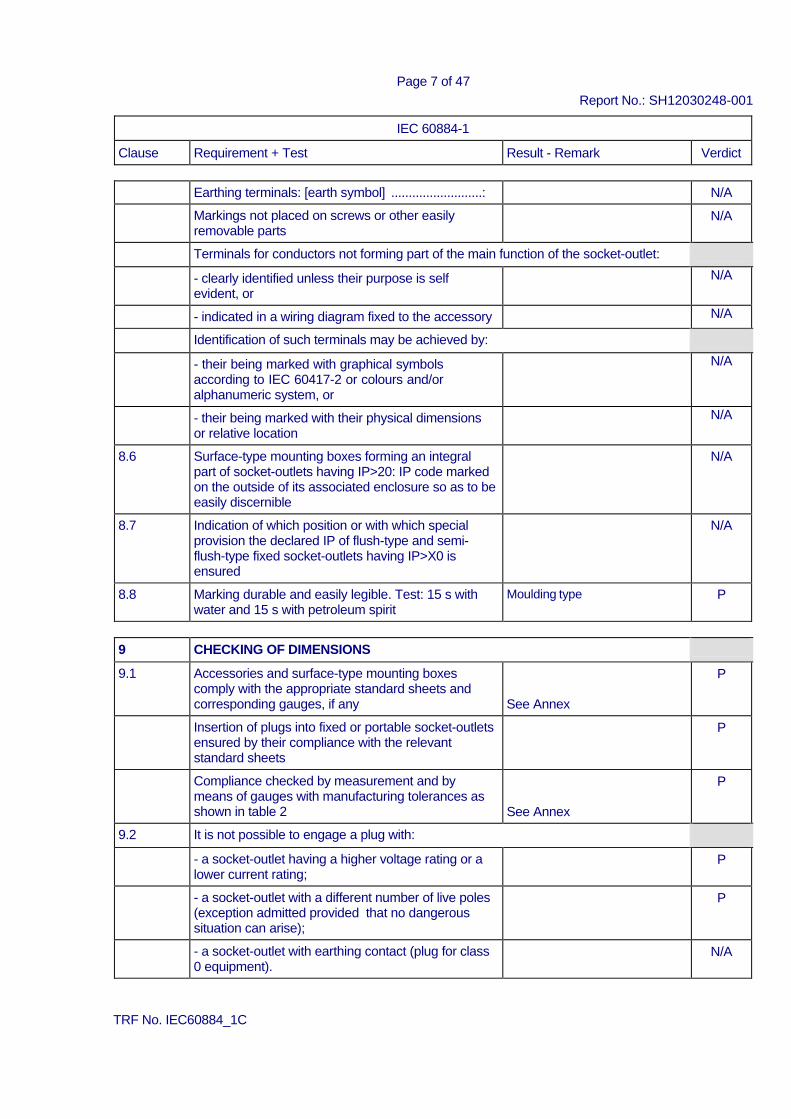
IEC 60884-1 Clause Requirement + Test Result - Remark Verdict
Earthing terminals: [earth symbol] ..........................: N/A Markings not placed on screws or other easily
removable parts N/A
Terminals for conductors not forming part of the main function of the socket-outlet: - clearly identified unless their purpose is self
evident, or N/A
- indicated in a wiring diagram fixed to the accessory N/A Identification of such terminals may be achieved by: - their being marked with graphical symbols
according to IEC 60417-2 or colours and/or alphanumeric system, or
N/A
- their being marked with their physical dimensions or relative location
N/A
8.6 Surface-type mounting boxes forming an integral part of socket-outlets having IP>20: IP code marked on the outside of its associated enclosure so as to be easily discernible
N/A
8.7 Indication of which position or with which special provision the declared IP of flush-type and semi- flush-type fixed socket-outlets having IP>X0 is ensured
N/A
8.8 Marking durable and easily legible. Test: 15 s with water and 15 s with petroleum spirit
Moulding type P
9 CHECKING OF DIMENSIONS 9.1 Accessories and surface-type mounting boxes
comply with the appropriate standard sheets and corresponding gauges, if any
See Annex
P
Insertion of plugs into fixed or portable socket-outlets ensured by their compliance with the relevant standard sheets
P
Compliance checked by measurement and by means of gauges with manufacturing tolerances as shown in table 2
See Annex
P
9.2 It is not possible to engage a plug with: - a socket-outlet having a higher voltage rating or a
lower current rating; P
- a socket-outlet with a different number of live poles (exception admitted provided that no dangerous situation can arise);
P
- a socket-outlet with earthing contact (plug for class 0 equipment).
N/A
TRF No. IEC60884_1C
Page 8 of 47 Report No.: SH12030248-001
IEC 60884-1 Clause Requirement + Test Result - Remark Verdict
Engagement of a plug for class 0 or class I
equipment with a socket-outlet designed to accept plugs for class II equipment, not possible
P
Impossibility of insertion checked by applying a gauge, for 1 min, with a force of: - 150 N (rated current ≤ 16A); P - 250 N (rated current > 16A) N/A Accessories with elastomeric or thermoplastic
material: test carried out at (35 ± 2) °C P
9.3 Deviations from standard sheets made only if they provide technical advantage and do not affect the purpose and safety of accessories complying with standard sheet
N/A
10 PROTECTION AGAINST ELECTRIC SHOCK 10.1 Socket-outlets: live parts not accessible N/A Live parts of plugs: not accessible when the plug is
in partial or complete engagement with a socket- outlet
P
Test with test probe B of IEC 61032 P Accessories with elastomeric or thermoplastic
material: additional test carried out at (35 ± 2) °C with test probe 11 of IEC 61032 (75 N for 1 min)
P
During the test: accessories not deform and no live parts accessible
P
Plugs and portable socket-outlets pressed with a force of 150 N for 5 min as shown in figure 8: specimens not show deformation
P
10.2 Accessible parts (with exception of small screws and the like for fixing bases and covers or cover plates): made of insulating material
P
Cover or cover plates of fixed socket-outlets and accessible parts of plugs and portable socket-outlets: made of metal if the requirements of 10.2.1 or 10.2.2 are fulfilled
N/A
10.2.1 Metal covers or cover plates protected by supplementary insulation made by insulating linings or insulating barriers
N/A
Insulating linings or insulating barriers cannot be removed without being permanently damaged
N/A
Insulating linings or insulating barriers cannot be replaced in an incorrect position and, if they are omitted, accessories are rendered inoperable or manifestly incomplete
N/A
TRF No. IEC60884_1C
Page 9 of 47 Report No.: SH12030248-001
IEC 60884-1 Clause Requirement + Test Result - Remark Verdict
There is no risk of accidental contact between live
parts and metal covers or cover plates N/A
10.2.2 Metal covers or cover plates automatically connected, through a low-resistance connection, to the earth during fixing
N/A
10.3 Contact between a pin of a plug and a live socket- contact of a socket-outlet not possible while any other pin is accessible
P
Compliance checked by manual test and by means of gauges with tolerances as specified in table 2
P
Accessories with elastomeric or thermoplastic material: test carried out at (35 ± 2) °C
P
Socket-outlets with enclosure or bodies of rubber or polyvinyl chloride: test carried out with a force of 75 N for 1 min
N/A
Fixed socket-outlets provided with metal covers or cover plates: clearance of at least 2 mm required between a pin and a socket-contact when another pin(s) is(are) in contact with the metal covers or cover plates (mm).....................................................:
N/A
10.4 External parts of plugs made of insulating material P Overall dimensions of rings around pins not exceed
8 mm concentric with respect to the pin N/A
10.5 Shuttered socket-outlets: live parts not accessible, without a plug in engagement, with the gauges shown in figure 9 and 10
N/A
Live contacts automatically screened when the plug is withdrawn
N/A
Means cannot easily be operated by anything other than a plug and not depend upon parts which are liable to be lost
N/A
Gauge of figure 9, applied to the entry holes corresponding to live contacts with a force of 20 N, for approximately 5 s, successively in three directions, does not touch live parts
N/A
Steel gauge of figure 10, applied to the entry holes corresponding to live contacts with a force of 1 N for approximately 5 s, in three directions, does not touch live parts
N/A
Accessories with elastomeric or thermoplastic material: test carried out at (35 ± 2) °C
N/A
10.6 Earthing contacts of a socket-outlet designed that they cannot be deformed by the insertion of a plug
N/A
Test plug inserted into the socket-outlet with a force of 150 N for 1 min
TRF No. IEC60884_1C
Page 10 of 47 Report No.: SH12030248-001
IEC 60884-1 Clause Requirement + Test Result - Remark Verdict
10.6 Earthing contacts of a socket-outlet designed that
they cannot be deformed by the insertion of a plug N/A
After this test: socket-outlet still comply with the requirements of clause 9
N/A
10.7 Socket-outlet with increased protection: live parts not accessible
N/A
Test wire of 1 mm diameter (figure 10) applied with a force of 1 N on all accessible surfaces does not touch live parts
N/A
Accessories with elastomeric or thermoplastic material: test carried out at (35 ± 2) °C
N/A
11 PROVISION FOR EARTHING 11.1 Earth connection made before the current-carrying
contacts of the plug become live P
Current-carrying pins are separated before the earth connection is broken
P
11.2 Earthing terminals of rewirable accessories comply with clause 12
N/A
Earthing terminals of the same size as the corresponding terminals for the supply conductors
N/A
Earthing terminals of rewirable accessories: internal N/A Additional external earthing terminal of fixed socket-
outlets of size suitable for conductors of at least 6 mm2 ......................................................................... :
N/A
Earthing terminals of fixed socket-outlets: fixed to the base or to a part reliably fixed to the base
N/A
Earthing contacts of fixed socket-outlets: - fixed to the base, or N/A - fixed to the cover (reliably connected to the earthing
terminals; contact pieces silver plated or with adequate protection)
N/A
Parts of earthing circuit in one piece or reliably connected by riveting, welding, or the like
crimping
P
11.3 Accessible metal parts of fixed socket-outlets: permanently and reliably connected to the earthing terminal
N/A
11.4 Socket-outlets, having an IP>X0, with enclosure of insulating material and more than one cable inlet, provided with:
- an internal fixed earthing terminal, or N/A
TRF No. IEC60884_1C
Page 11 of 47 Report No.: SH12030248-001
IEC 60884-1 Clause Requirement + Test Result - Remark Verdict
- adequate space for a floating terminal (test
connection using the type of terminal specified by the manufacturer), unless
N/A
- earthing terminal of socket-outlet itself allows the connection of an incoming and an outgoing earthing conductor
N/A
11.5 Connection between earthing terminal and accessible metal parts: of low resistance
N/A
Test current equal to 1,5 times the rated current or 25 A (A) ................................................................... :
⎯
Resistance not exceed 0,05 Ω (Ω) ........................ : N/A 11.6 Fixed socket-outlets according to item b) of 7.2.5:
earthing socket contact and its terminal electrically separated from any metal mounting means or other exposed conductive parts which may be conncted to the protective earthing circuit of the installation
N/A
12 TERMINALS AND TERMINATIONS All the test on terminals, with the exception of the
tests of 12.3 11 and 12.3.12, made after the test of clause 16
P
12.1 General 12.1.1 Rewirable fixed socket-outlets provided with screw-
type terminals or with screwless terminals ............ : N/A
Rewirable plugs and portable socket-outlets provided with terminals with screw clamping ........ :
N/A
Pre-soldered flexible conductors used: pre-soldered area outside the clamp area of screw-type terminals
N/A
Clamping means of terminals: not serve to fix any other components
N/A
12.1.2 Non-rewirable accessories provided with soldered, welded, crimped or equally effective permanent connections (termination) ....................................... :
Crimped
P
Screwed or snap-on connections not used P Connections made by crimping a pre-soldered
flexible conductor not permitted N/A
12.2 Terminals with screw clamping for external copper conductors N/A 12.3 Screwless terminals for external copper conductors N/A
13 CONSTRUCTION OF FIXED SOCKET-OUTLETS N/A
14 CONSTRUCTION OF PLUGS AND PORTABLE SOCKET-OTLETS
TRF No. IEC60884_1C
Page 12 of 47 Report No.: SH12030248-001
IEC 60884-1 Clause Requirement + Test Result - Remark Verdict
14.1 Non-rewirable portable accessories: flexible cable cannot be separated from the
accessory without making it permanently useless P
Accessory cannot be opened by hand or by using a generaI purpose tool, for example a screwdriver used as such
P
14.2 Pins of portable accessories: adequate mechanical strength
Non-solid pin
P
Test for pins not solid (made after clause 21): force of 100 N exerted on the pin, according to figure 14, for 1 min by means of a steel rod Ø 4,8 mm
During the application of the force: reduction of the dimension of the pin not exceed 0,15 mm
0,08mm
P
After removal of the rod: dimensions of the pin not changed by more than 0,06 mm
0,03mm
P
14.3 Pins of plugs: - locked against rotation P - not removable without dismantling the plug P - adequately fixed in the body of the plug when the
plug is wired and assembled as in normal use P
Earthing or neutral pins or contacts of plugs: not possible to arrange in an incorrect position
P
14.4 Earthing contacts and neutral contacts of portable socket-outlets: - locked against rotation N/A - removable only with the aid of a tool, after
dismantling the socket-outlet N/A
14.5 Socket-contact assemblies: sufficient resilience N/A Parts of socket-contact assemblies: - are not of insulating material except ceramic, or
other material with no less suitable characteristics N/A
- ensure metallic contacts at least on two opposing sides of each pin
N/A
Contact pressure of the contact tube does not depend on soldered connection only
N/A
14.6 Pins and socket-contacts: resistant to corrosion and abrasion
P
14.7 Enclosures of rewirable portable accessories: completely enclose terminals and ends of flexible cable
N/A
Construction of rewirable accessories: - conductors can be properly connected N/A
TRF No. IEC60884_1C
Page 13 of 47 Report No.: SH12030248-001
IEC 60884-1 Clause Requirement + Test Result - Remark Verdict
- cores not pressed against each other N/A - cores of live conductor not pressed against
accessible metal parts N/A
- core of earthing conductor not pressed against live parts
N/A
14.8 Rewirable portable accessories: terminal screws or nuts cannot become loose and fall out of position and establish an electrical connection between live parts and earthing terminal or metal parts
N/A
14.9 Rewirable portable accessories with earthing contact: ampIe space for slack of earthing (test)
N/A
Non-rewirable non-moulded-on accessories with earthing contact: current-carrying conductors stressed before the earthing conductor if the flexible cable slips in its anchorage
N/A
14.10 Terminals of rewirable portable accessories and terminations of non-rewirable portable accessories: located and shielded that loose wires not present a risk of electric shock
P
Non-rewirable moulded-on portable accessories: provided with means to prevent loose wires of a conductor from reducing the minimum isolation distance requirements
P
14.10.1 Rewirable accessories: test with 6 mm free wire free wire of a conductor connected to a live
terminal not touch any accessible metal part or able to emerge from the enclosure
N/A
free wire of a conductor connected to an earthing terminal not touch a live part
N/A
14.10.2 Non-rewirable, non-moulded-on accessories: test with a free wire of length equivalent to the maximum designed stripping length declared by the manufacturer plus 2 mm
N/A
free wire of a conductor connected to a live termination not touch any accessible metal part or reduce creepage distance and clearance below 1,5 mm to the external surface
N/A
free wire of a conductor connected to an earth termination not touch any live part
N/A
14.10.3 Non-rewirable, moulded-on accessories: Verification of means to prevent stray wires
reducing the minimum distance through insulation to external accessible surface below 1,5 mm
P
14.11 Rewirable portable accessories:
TRF No. IEC60884_1C
Page 14 of 47 Report No.: SH12030248-001
IEC 60884-1 Clause Requirement + Test Result - Remark Verdict
- clear how relief from strain and prevention of
twisting is intended to be effected N/A
- cord anchorage, or at Ieast part of it, integraI with or fixed to one of the component parts of the plug or portable socket-outlet
N/A
- makeshift methods not used N/A - cord anchorage suitable for the different types of
flexible cable which may be connected to it; screws, if any: not serve to fix any other component
N/A
- cord anchorages: of insulating material or provided with an insulating lining fixed to the metal parts
N/A
- metal parts of cord anchorages, including clamping screws: insulated from the earthing circuit
N/A
14.12 Rewirable portable accessories and non-rewirable non-moulded on portable accessories: it is not possible to remove covers, cover-plates or parts of them intended to ensure protection against electric shock without the use of a tool
N/A
14.13 Covers of portable socket-outlets: bushings for entry holes for the pins not removable from the outside or detachable inadvertently from the inside
N/A
14.14 Screws intended to allow access to interior of the accessory: captive
N/A
14.15 Engagement face of plugs: no projections P 14.16 Engagement face of portable socket-outlets: no
projection N/A
14.17 Portable accessories of IP>20: enclosed according to their IP classification
IP20
N/A
Plugs having IP>20: adequately enclosed with the exception of the engagement face
N/A
Portable socket-outlets having IP>20: adequately enclosed without a plug in engagement
N/A
Lid springs (if any): of corrosion-resistant material (bronze or stainless steel) ......................................:
N/A
14.18 Portable socket-outlets: means for suspension from a wall or other mounting surfaces not allow access to live parts
N/A
No free openings between space intended for suspension means by which the socket-outlet is fixed to the wall, or other mounting surface and live parts
N/A
TRF No. IEC60884_1C
Page 15 of 47 Report No.: SH12030248-001
IEC 60884-1 Clause Requirement + Test Result - Remark Verdict
14.19 Combinations of portable accessories and
switches, circuit-breakers or other devices comply with relevant individual IEC standards, if relevant combined product standard does not exist ...........:
N/A
14.20 Portable accessories: not integral part of Iampholders
P
14.21 Plugs for equipment of class II: N/A - rewirable or non-rewirable N/A - if part of a cord set: provided with a connector for
equipment of class II N/A
- if part of a cord extension set: provided with a portable socket-outlet for equipment of class II
N/A
14.22 Components (switches and fuses) incorporated in accessories: comply with the relevant IEC standard
N/A
14.23 Plug-in equipment: not cause overheating of the pins or impose undue strain
N/A
Plugs with rating above 16 A and 250 V: not integral part of other equipment
N/A
Tests for two-pole plugs, with or without earthing contact, with rating up to and including 16 A and 250 V (plug of equipment inserted into a fixed socket-outlet complying with this standard):
14.23.1 Socket-outlet connected to a supply voltage equal to 1,1 times the highest rated voltage of the equipment (V) .........................................................:
⎯
Temperature rise of the pins after 1 h not exceed 45 K (K) ...................................................................:
N/A
14.23.2 Additional torque applied to the socket-outlet in order to maintain the engagement face in the vertical plane not exceed 0,25 Nm (Nm) ..............:
N/A
14.24 Plugs can easily withdrawn by hand from the relevant socket-outlets
P
Gripping surfaces are so designed that the plug can be withdrawn without having to pull the flexible cable
P
14.25 Membranes in inlet openings of portable accessorie: meet the requirements of 13.22 and 13.23
N/A
15 INTERLOCKED SOCKET-OUTLETS N/A
16 RESISTANCE TO AGEING, PROTECTION PROVIDED BY ENCLOSURES, AND RESISTANCE TO HUMIDITY
TRF No. IEC60884_1C
Page 16 of 47 Report No.: SH12030248-001
IEC 60884-1 Clause Requirement + Test Result - Remark Verdict
16.1 Resistance to ageing Accessories are resistant to ageing P Portable socket-outlets: test plug as specified in
Clause 20 inserted into the socket-outlets N/A
Accessories subjected to a test in a heating cabinet at (70 ± 2) °C for seven days (168 h)
P
After the tests, the specimens show: - no crack visible with normal or corrected vision
without additional magnification P
- no sticky or greasy material P - no trace of cloth (forefinger pressed with 5 N) P - no damage P Portable socket-outlets: contact pressure of the
contact assembly checked as specified in subclause 22.2 with the single-pin gauge
N/A
16.2 Protection provided by enclosures Enclosures provide a degree of protection in
accordance with the IP designation of the accessory
IP20
P
16.2.1 Protection against access to hazardous parts and against harmful effects due to ingress of solid foreign objects
Accessories and their enclosures provide a degree of protection against access to hazardous parts and against harmful effects due to ingress of solid foreign objects
IP20
P
Fixed socket-outlets: mounted as in normal use on a vertical surface
N/A
Flush-type and semi-flush type socket-outlets: mounted in an appropriate box according to the manufacturer’s instructions
N/A
Accessories with screwed glands or membranes fitted with flexible cables within the range specified in table 3:
- largest cross-sectional area (mm2); type of cable (table 17) .................................................................:
⎯
- smallest cross-sectional area (mm2); type of cable (table 17) .................................................................:
⎯
Glands tightened with a torque equal to 2/3 of the torque applied during the test of 24.6 (Nm) ..........:
⎯
Screws of the enclosure tightened with a torque equal to 2/3 of the torque given in table 6 (Nm) ...:
⎯
16.2.1.1 Protection against access to hazardous parts
TRF No. IEC60884_1C
Page 17 of 47 Report No.: SH12030248-001
IEC 60884-1 Clause Requirement + Test Result - Remark Verdict
Appropriate test performed as specified in IEC
60529 (see also clause 10) IP20
P
16.2.1.2 Protection against harmful effects due to ingress of solid foreign objects Appropriate test performed as specified in IEC
60529 IP20
P
Test on accessories with IP5X (considered to be of category 2): dust not penetrated in a quantity to interfere with satisfactory operation or to impair safety
N/A
16.2.2 Protection against harmful effects due to ingress of water Accessories and their enclosures provide a degree
of protection against harmful effects due to ingress of water in accordance with their IP classification
IP20
N/A
Appropriate test performed as specified in IEC 60529 under the following conditions:
Flush-type and semi-flush type socket-outlets: fixed in a vertical test wall using an appropriate box according to the manufacturer’s instructions
N/A
Accessory suitable to be installed on a rough wall: test wall according to figure 15 is used
N/A
Surface-type socket-outlets mounted as for normal use in a vertical position and fitted with cables (having conductors of the largest and smallest nominal cross- sectional area given in table 3) or conduits or both in accordance with the manufacturer’s instructions:
- largest cross-sectional area (mm2); type of cable (table 17) .................................................................:
⎯
- smallest cross-sectional area (mm2); type of cable (table 17) .................................................................:
⎯
Portable socket-outlets tested on a plain, horizontal surface in a position as in normal use and fitted with flexible cables (having conductors of the largest and smallest nominal cross-sectional area given in table 3) according to table 17:
- largest cross-sectional area (mm2); type of cable (table 17) .................................................................:
⎯
- smallest cross-sectional area (mm2); type of cable (table 17) .................................................................:
⎯
Screws of enclosure tightened with a torque equal to 2/3 of the torque given in table 6 (Nm) .............:
⎯
Glands tightened with a torque equal to 2/3 of the torque applied during the test of 24.6 (Nm) ..........:
⎯
Accessory with drain holes opened during the test: any accumulation of water proved by inspection
N/A
Socket-outlets tested without a plug in engagement N/A
TRF No. IEC60884_1C
Page 18 of 47 Report No.: SH12030248-001
IEC 60884-1 Clause Requirement + Test Result - Remark Verdict
Plugs tested when in full engagement with: - a fixed socket-outlets N/A - a portable socket-outlets N/A of the same system and with the same degree of
protection against harmful effects due to ingress of water
⎯
Specimens withstand an electric strength test specified in 17.2 which is started within 5 min of completion of the IP test
N/A
16.3 Resistance to humidity Accessories proof against humidity which may
occur in normal use P
Compliance checked by a humidity treatment carried out in a humidity cabinet containing air with relative humidity maintained between 91 % and 95 %
93% P
Specimens kept in the cabinet for: - two days (48 h) for accessories having IPX0 IP20 P - seven days (168 h) for accessories having IP>X0 N/A After this treatment the specimens show no
damage P
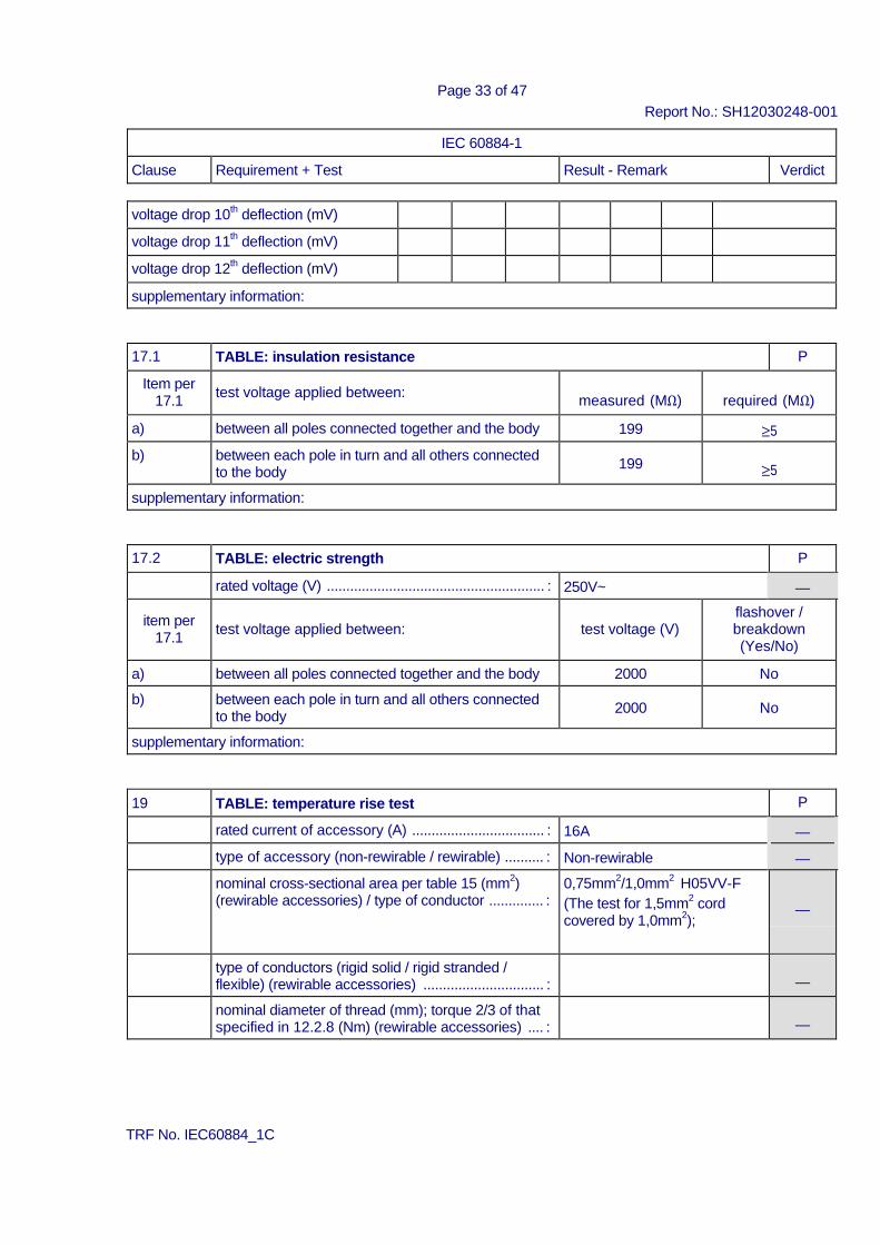
17 INSULATION RESISTANCE AND ELECTRIC STRENGTH 17.1 Insulation resistance measured 1 min after
application of 500 V d.c. See appended table 17.1
P
17.2 Electric strength: a.c. test voltage applied for 1 min See appended table 17.2 P
18 OPERATION OF EARTHING CONTACTS Earthing contacts provide adequate contact
pressure and not deteriorate in normal use N/A
Compliance checked by the tests of clauses 19 and 21
N/A
19 TEMPERATURE RISE Temperature rise test See appended table 19 P Socket-outlets tested using a test plug with brass
pins having the minimum specified dimensions N/A
Plugs tested with clamping units having dimensions specified in Figure 44 fitted on each live pin and earthing pin, if any
P
TRF No. IEC60884_1C
Page 19 of 47 Report No.: SH12030248-001
IEC 60884-1 Clause Requirement + Test Result - Remark Verdict
Plugs having lateral earthing contacts and resilient
earthing contacts tested using a fixed socket-outlet complying with the standard and having as near to- average characteristics as can be selected, but with minimum size of the earthing pin, if any
N/A
20 BREAKING CAPACITY Accessories have adequate breaking capacity P Compliance checked by testing: - socket-outlets; See appended table 20 N/A - plugs with pins which are not solid See appended table 20 P Multiple socket-outlets: test carried out on one
socket-outlet of each type and current rating See appended table 20
N/A
During the test: no sustained arcing occur P After the test: - specimens show no damage impairing their
further use; P
- entry holes for the pins not show any damage which may impair the safety
N/A
21 NORMAL OPERATION Accessories withstand without excessive wear or
other harmful effect, the mechanical, electrical and thermal stresses occurring in normal use
P
Compliance checked by testing: - socket-outlets; See appended table 21 N/A - plugs with resilient earthing socket-contacts; See appended table 21 N/A - plugs with pins which are not solid See appended table 21 P Test performed according to the procedure
specified in Figure 43; point of Figure 43 at which the test program has begun (1, 2, 3) ................... :
⎯
Test current passed: - during each insertion and withdrawal of the plug
(In ≤ 16A) P
- during alternate insertion and withdrawal, the other insertion and withdrawal being made without current flowing (In > 16A)
N/A
Multiple socket-outlets: test carried out on one socket-outlet of each type and current rating
See appended table 20
N/A
During the test: no sustained arcing occur P After the test the specimens do not show:
TRF No. IEC60884_1C
Page 20 of 47 Report No.: SH12030248-001
IEC 60884-1 Clause Requirement + Test Result - Remark Verdict
- wear impairing their further use; P - deterioration of enclosures, insulating lining or
barriers; P
- damage to the entry holes for the pins, that might impair proper working;
N/A
- loosening of electrical or mechanical connections; P - seepage of sealing compound N/A Shuttered socket-outlets: gauges of figure 9 and 10
applied to the entry holes corresponding to live contacts do not touch live parts when they remain under the relevant forces
See appended table 21
N/A
Temperature-rise test (requirements of clause 19) See appended table 21 P Electric strength (sub-clause 17.2) See appended table 21 P Pins which are not solid: test according to 14.2 P
22 FORCE NECESSARY TO WITHDRAW THE
PLUG
Construction of accessory does allow the easy insertion and withdrawal of the plug, and prevent the plug from working out of the socket-outlet in normal use
N/A
22.1 Verification of the maximum withdrawal force See appended table 22 N/A
22.2 Verification of the minimum withdrawal force See appended table 22 N/A
23 FLEXIBLE CABLES AND THEIR CONNECTIONS 23.1 Rewirable plugs and rewirable portable socket-
outlets are provided with a cord anchorage N/A
Sheath of flexible cable is clamped within the cord anchorage
N/A
In non-rewirable plugs and non-rewirable portable socket-outlets the cable is maintained in position and the terminations are relieved from strain and twisting
P
Sheath of flexible cable is maintained inside the accessory
P
23.2 Pull and torque test Non-rewirable accessories: P After the test: displacement ≤ 2 mm See appended table 23.2 P No break in the electrical connections P Rewirable accessories: N/A
TRF No. IEC60884_1C
Page 21 of 47 Report No.: SH12030248-001
IEC 60884-1 Clause Requirement + Test Result - Remark Verdict
After the test: displacement ≤ 2 mm N/A End of conductors not have moved noticeably in
the terminals N/A
Rewirable accessories having rated current up to and including 16 A: Suitable for fitting with the appropriate cable as
shown in table 19 N/A
Type of flexible cable; number of conductors and nominal cross-sectional area (mm2) ..................... :
⎯
23.3 Non-rewirable plugs and non-rewirable portable socket-outlets are provided with a flexible cable complying with IEC 60227 or IEC 60245
IEC 60227
P
Flexible cables have the same number of conductors as there are poles in the plug or socket- outlet
P
Conductor connected to the earthing contact is identified by the colour combination green/yellow
P
23.4 Non-rewirable plugs and non-rewirable portable socket-outlets: designed that the flexible cable is protected against excessive bending
P
Guards of insulating material and fixed in reliable manner
P
Flexing test (10.000 flexings) P During the test: no interruption of the test current
and no short-circuit between conductors See appended table 23.4
P
After the test: guard no separated from the body, insulation shows no sign of abrasion or wear, broken strands become no accessible
See appended table 23.4
P
24 MECHANICAL STRENGTH Accessories, surface mounting boxes, screwed
glands and shrouds have adequate mechanical strength
P
24.1 Fixed socket-outlets, portable multiple socket- outlets and surface-type mounting boxes: impact test (apparatus shown in fig. 22, 23, 24 and 25)
See appended table 24.1
N/A
After the test: no damage, live parts no become accessible
N/A
24.2 Portable single socket-outlets and plugs: subjected to test Ed: Free fall, procedure 2 of IEC 60068-2-32 (tumbling barrel); number of falls ......................... :
1000
P
After the test: - no part become detached or loosened; P
TRF No. IEC60884_1C
Page 22 of 47 Report No.: SH12030248-001
IEC 60884-1 Clause Requirement + Test Result - Remark Verdict
- pins no become so deformed that the plug cannot
be introduced into a socket-outlet and also fails to comply with the requirements of 9.1 and 10.3;
P
- pins no turn when a torque of 0,4 Nm is applied for 1 min in each direction
P
24.3 Bases of surface-type socket-outlets: first fixed to a cylinder of rigid steel sheet and then fixed to a flat steel sheet
N/A
During and after the tests: no damage N/A 24.4 Portable single socket-outlets, multiple socket-outlets and plugs (elastomeric or
thermoplastic material): impact test, weight (1000 ± 2) g, height 100 mm (apparatus shown in fig. 27)
P
Specimens placed in a freezer at (-15 °C ± 2) °C for at least 16 h. After the test: no damage
P
24.5 Portable single socket-outlets and plugs (elastomeric or thermoplastic material): compression test, 300 N for 1 min, position a) and b) (apparatus shown in fig. 8)
P
After the test: no damage P 24.6 Screwed glands of accessories having IP>20: torque test (1 min) N/A - diameter of test rod (mm) ................................... : ⎯ - type of material (metal / moulded) ...................... : ⎯ - torque (Nm) .......................................................... : ⎯ After the test: no damage of glands and enclosures
of the specimens N/A
24.7 Plug pins provided with insulating sleeves: 20000 movements, 4 N (apparatus shown in fig. 28)
P
After the test: no damage of pins, insulating sleeve not have punctured or rucked up
P
24.8 Shuttered socket-outlets: mechanical test carried out on specimens submitted to the normal operation test according to clause 21
N/A
Force (40 N / 75 N) applied for 1 min against the shutter of an entry hole by means of one pin (N) :
⎯
Pin did not come in contact with live parts N/A After the test: no damage N/A 24.9 Mechanical test for multiple portable socket-outlet: 8 falls on concrete floor with the
specimens arranged as shown in figure 29 N/A
Rewirable multiple socket-outlets: flexible cable of the smallest cross-sectional area specified in table 3 ...............................................................................:
⎯
After the test: no damage, no part have become detached or loosened
N/A
Accessories having IP>X0 submitted again to the tests as specified in 16.2
N/A
TRF No. IEC60884_1C
Page 23 of 47 Report No.: SH12030248-001
IEC 60884-1 Clause Requirement + Test Result - Remark Verdict
24.10 Plugs: pull test to verify the fixation of pins in the body of the plug (new specimens) P Maximum withdrawal force (table 16) applied for 1
min on each pin in turn, after the specimen has been placed at (70 ± 2) °C for 1 h (N) .................. :
54N ⎯
After the test: displacement of pins in the body of the plug ≤ 1 mm (mm) ........................................... :
0.4mm
P
24.11 Barriers of portable socket-outlets having means for suspension on a mounting surface:
N/A
Force applied for 10 s against the barrier by means of a cylindrical steel rod (1,5 times the maximum plug withdrawal force in 22.1, table 16) (N) ......... :
⎯
Rod did not pierce the barrier N/A 24.12 Portable socket-outlets having means for suspension on a mounting surface (pull
test): N/A
Pull applied to the supply flexible cable for 10 s (force prescribed in 23.2 for checking the flexible cable anchorage) (N) ............................................ :
⎯
During the test: no break of the means for suspension on a mounting surface
N/A
24.13 Portable socket-outlets having means for suspension on a mounting surface (pull test):
N/A
Pull applied to the engagement face of the socket- outlet for 10 s (maximum withdrawal force specified, for the corresponding plug, in table 16) (N) ........................................................................... :
⎯
During the test: no break of the means for suspension on a mounting surface
N/A
24.14 Forces necessary to retain or remove covers, cover-plates or parts of them (accessibility with the test finger to live parts)
N/A
24.14.1 Verification of the retention of covers or cover-plates (fixed socket-outlets) N/A Force (40 N / 80 N) applied for 1 min perpendicular
to the mounting surface (N) .................................. :
⎯ Covers or cover-plates did not come off N/A Test repeated on new specimens with a sheet of
hard material, (1 ± 0,1) mm thick, fitted around the supporting frame (fig. 31): covers or cover-plates did not come off
N/A
After the test: no damage N/A 24.14.2 Verification of the removal of covers or cover-plates (fixed socket-outlets) N/A Force not exceeding 120 N applied 10 times
perpendicular to the mounting / supporting surface: covers or cover-plates came off
N/A
TRF No. IEC60884_1C
Page 24 of 47 Report No.: SH12030248-001
IEC 60884-1 Clause Requirement + Test Result - Remark Verdict
Test repeated on new specimens with a sheet of
hard material, (1 ± 0,1) mm thick, fitted around the supporting frame (fig. 31): covers or cover-plates came off
N/A
After the test: no damage N/A 24.14.3 Verification of the retention of covers or cover-plates (plugs and portable socket-
outlets) N/A
Force 80 N applied for 1 min perpendicular to the mounting surface: covers, cover-plates or parts of them did not come off
N/A
Test repeated with a force of 120 N: N/A Rewirable plugs and rewirable portable socket-
outlets: covers, cover-plates or parts of them came off but the specimen showed no damage
N/A
Non-rewirable, non moulded-on accessories: covers, cover-plates or parts of them came off but the accessories were permanently useless according to 14.1
N/A
24.15 Force necessary for covers or cover-plates to come off or not to come off (accessibility with the test finger to non-earthed metal parts separated from live parts by creepage distances and clearances according to table 23)
N/A
24.14.1 Verification of the non-removal of covers or cover-plates N/A Force (10 N / 20 N) applied for 1 min in direction
perpendicular to the mounting surface (N) .......... :
⎯ Covers or cover-plates did not come off N/A Test repeated on new specimens with a sheet of
hard material, 1 mm ± 0,1 mm thick, fitted around the supporting frame (fig. 31): covers or cover- plates did not come off
N/A
After the test: no damage N/A 24.14.2 Verification of the removal of covers or cover-plates N/A Force not exceeding 120 N applied 10 times in
direction perpendicular to the mounting / supporting surface: covers or cover-plates came off
N/A
Test repeated on new specimens with a sheet of hard material, 1 mm ± 0,1 mm thick, fitted around the supporting frame (fig. 31): covers or cover- plates came off
N/A
After the test: no damage N/A 24.16 Force necessary for covers or cover-plates to come off or not to come off
(accessibility to insulating parts, earthed metal parts, live parts of SELV ≤ 25 V a.c. or metal parts separated from live parts by creepage distances twice those according to table 23)
N/A
TRF No. IEC60884_1C
Page 25 of 47 Report No.: SH12030248-001
IEC 60884-1 Clause Requirement + Test Result - Remark Verdict
24.14.1 Verification of the non-removal of covers or cover-plates N/A Force 10 N applied for 1 min in direction
perpendicular to the mounting surface: covers or cover-plates did not come off
N/A
Test repeated on new specimens with a sheet of hard material, 1 mm ± 0,1 mm thick, fitted around the supporting frame (fig. 31): covers or cover- plates did not come off
N/A
After the test: no damage N/A 24.14.2 Verification of the removal of covers or cover-plates N/A Force not exceeding 120 N applied 10 times in
direction perpendicular to the mounting / supporting surface: covers or cover-plates came off
N/A
Test repeated on new specimens with a sheet of hard material, 1 mm ± 0,1 mm thick, fitted around the supporting frame (fig. 31): covers or cover- plates came off
N/A
After the test: no damage N/A 24.17 Test with gauge of figure 7 applied according to
figure 9 for verification of the outline of covers or cover-plates: distances between face C of gauge and outline of side under test, not decrease ....... :
⎯
24.18 Test with gauge according to figure 5 applied as shown in figure 11 (1 N): gauge not enter more than 1mm ............................................................... :
⎯
24.19 Shroud of portable socket-outlets: compression test (20 ± 2) N at (25 ± 5) °C by means of the apparatus shown in figure 38
N/A
After 1 min and while the shrouds are still under pressure the dimensions did comply with the appropriate standard sheet
N/A
Test repeated with the specimen rotated 90 ° N/A
25 RESISTANCE TO HEAT 25.1 Specimens kept for 1 h in a heating cabinet at (100 ± 2) °C for 1 h During the test: no change impairing their further use
and sealing compound, if any, not flow P
After the test: - no access to live parts with probe B of IEC 61032
applied with a force not exceeding 5 N P
- markings still legible P
TRF No. IEC60884_1C
Page 26 of 47 Report No.: SH12030248-001
IEC 60884-1 Clause Requirement + Test Result - Remark Verdict
25.2 Parts of insulating material necessary to retain
current-carrying parts and parts of the earthing circuit in position, as well as parts of the front surface zone, 2 mm wide, surrounding the phase and neutral pin entry holes: ball-pressure test at (125 ± 2)°C for 1 h
See appended table 25.2
P
25.3 Parts of insulating material not necessary to retain current-carrying parts and parts of the earthing circuit in position, even though in contact with them: ball- pressure test (1 h)
See appended table 25.3
N/A
25.4 Portable accessories: compression test (20 N) at (80 ± 2)°C for 1 h by means of the apparatus shown in figure 38
After the test: no damage P
26 SCREWS, CURRENT-CARRYING PARTS AND CONNECTIONS 26.1 Connections withstand mechanical stresses Thread-forming or thread-cutting screws used only
if supplied together with the piece in which they are intended to be inserted
N/A
Thread-cutting screws intended to be used during installation: captive
N/A
Screws and nuts which transmit contact pressure: in engagement with a metal thread
N/A
Threaded part torque test N/A 26.2 Screws in engagement with a thread of insulating
material: correct introduction into the screw hole or nut ensured
N/A
26.3 Contact pressure: not transmitted through insulating material other than ceramic, pure mica or other material no less suitable unless there is sufficient resiliency in metallic parts
P
Connections made by insulation piercing of tinsel cord reliable
N/A
26.4 Screws and rivets locked against loosening and/or turning
N/A
26.5 Current-carrying parts (including earthing terminals) have mechanical strength, electrical conductivity and resistance to corrosion adequate:
- copper; N/A - alloy with at least 58 % copper for parts made from
cold-rolled sheet or with at least 50 % copper for other parts;
>59%
P
- stainless steel with at least 13 % chromium and not more than 0,09 % carbon
N/A
TRF No. IEC60884_1C
Page 27 of 47 Report No.: SH12030248-001
IEC 60884-1 Clause Requirement + Test Result - Remark Verdict
- steel with electroplated coating of zinc (ISO 2081):
service condition ISO no. (1/2/3); IP (X0/X4/X5); thickness (µm) ........................................................... :
N/A
- steel with electroplated coating of nickel and chromium (ISO 1456): service condition ISO no. (2/3/4); IP (X0/X4/X5); thickness (µm) ...................... :
N/A
- steel with electroplated coating of tin (ISO 2093): service condition ISO no. (2/3/4); IP (X0/X4/X5); thickness (µm) ........................................................... :
N/A
Current-carrying parts subjected to mechanical wear: not of steel with electroplated coating
P
Metals having a great difference of electrochemical potential: not used in contact with each other
N/A
26.6 Contacts subjected to a sliding action are of metal resistant to corrosion
N/A
26.7 Thread-forming screws and thread-cutting screws are not used for the connection of current-carrying parts
P
Thread-forming screws and thread-cutting screws used to provide earthing connection: it is not necessary to disturb the connection and at least two screws are used for each connection
N/A
27 CREEPAGE DISTANCES, CLEARANCES AND DISTANCES THROUGH SEALING
COMPOUND
27.1 Creepage distances, clearances and distances through sealing compound are not less than the values shown in table 23
See appended table 27.1
P
27.2 Insulating sealing compound does not protrude above the edge of the cavity in which it is contained
N/A
27.3 Surface-type socket-outlets do not have bare current-carrying strips at the back
N/A
28 RESISTANCE OF INSULATING MATERIAL TO ABNORMAL HEAT, TO FIRE AND
TO TRACKING
28.1 Resistance to abnormal heat and to fire 28.1.1 Glow-wire test according to IEC 60695-2-10 and IEC
60695-2-11 See appended table 28.1.1
P
28.1.2 Plugs with pins provided with insulating sleeves: P Test temperature maintained for 3 h by means of the
apparatus shown in figure 40 at (120 ± 5) °C / (180 ± 5) °C ........................................................................ :
180°C ⎯
TRF No. IEC60884_1C
Page 28 of 47 Report No.: SH12030248-001
IEC 60884-1 Clause Requirement + Test Result - Remark Verdict
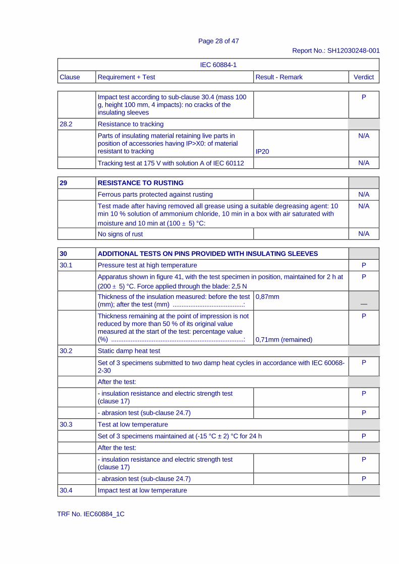
Impact test according to sub-clause 30.4 (mass 100
g, height 100 mm, 4 impacts): no cracks of the insulating sleeves
P
28.2 Resistance to tracking Parts of insulating material retaining live parts in
position of accessories having IP>X0: of material resistant to tracking
IP20
N/A
Tracking test at 175 V with solution A of IEC 60112 N/A
29 RESISTANCE TO RUSTING Ferrous parts protected against rusting N/A Test made after having removed all grease using a suitable degreasing agent: 10
min 10 % solution of ammonium chloride, 10 min in a box with air saturated with moisture and 10 min at (100 ± 5) °C:
N/A
No signs of rust N/A
30 ADDITIONAL TESTS ON PINS PROVIDED WITH INSULATING SLEEVES 30.1 Pressure test at high temperature P Apparatus shown in figure 41, with the test specimen in position, maintained for 2 h at
(200 ± 5) °C. Force applied through the blade: 2,5 N P
Thickness of the insulation measured: before the test (mm); after the test (mm) ........................................:
0,87mm ⎯
Thickness remaining at the point of impression is not reduced by more than 50 % of its original value measured at the start of the test: percentage value (%) ...........................................................................:
0,71mm (remained)
P
30.2 Static damp heat test Set of 3 specimens submitted to two damp heat cycles in accordance with IEC 60068-
2-30 P
After the test: - insulation resistance and electric strength test
(clause 17) P
- abrasion test (sub-clause 24.7) P 30.3 Test at low temperature Set of 3 specimens maintained at (-15 °C ± 2) °C for 24 h P After the test: - insulation resistance and electric strength test
(clause 17) P
- abrasion test (sub-clause 24.7) P 30.4 Impact test at low temperature
TRF No. IEC60884_1C
Page 29 of 47 Report No.: SH12030248-001
IEC 60884-1 Clause Requirement + Test Result - Remark Verdict
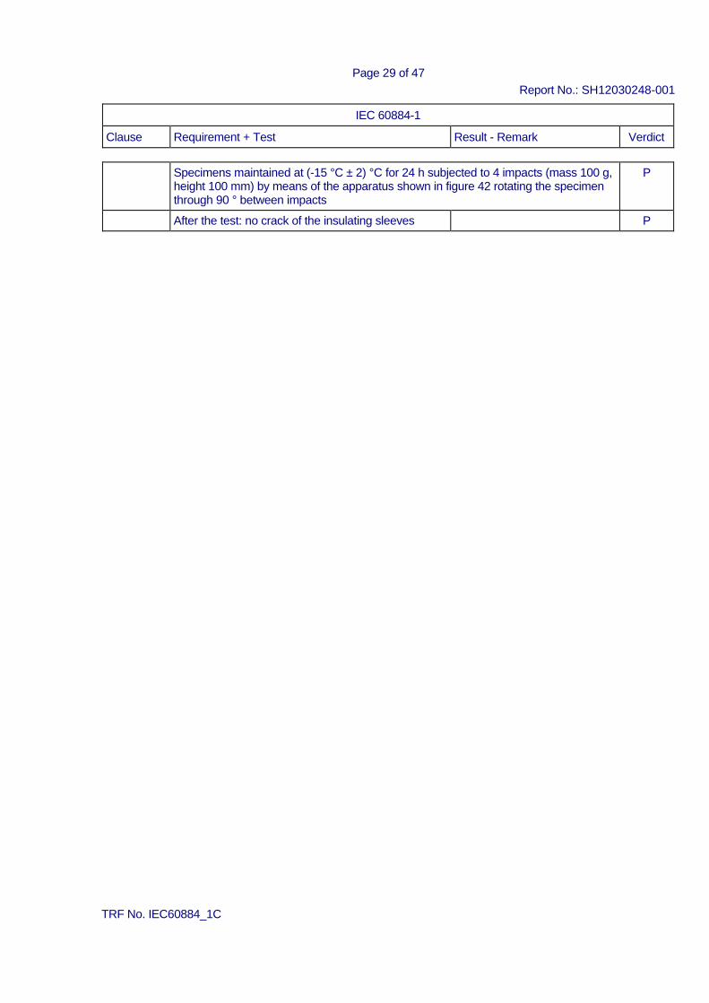
Specimens maintained at (-15 °C ± 2) °C for 24 h subjected to 4 impacts (mass 100 g,
height 100 mm) by means of the apparatus shown in figure 42 rotating the specimen through 90 ° between impacts
P
After the test: no crack of the insulating sleeves P
TRF No. IEC60884_1C
Page 30 of 47 Report No.: SH12030248-001
IEC 60884-1 Clause Requirement + Test Result - Remark Verdict
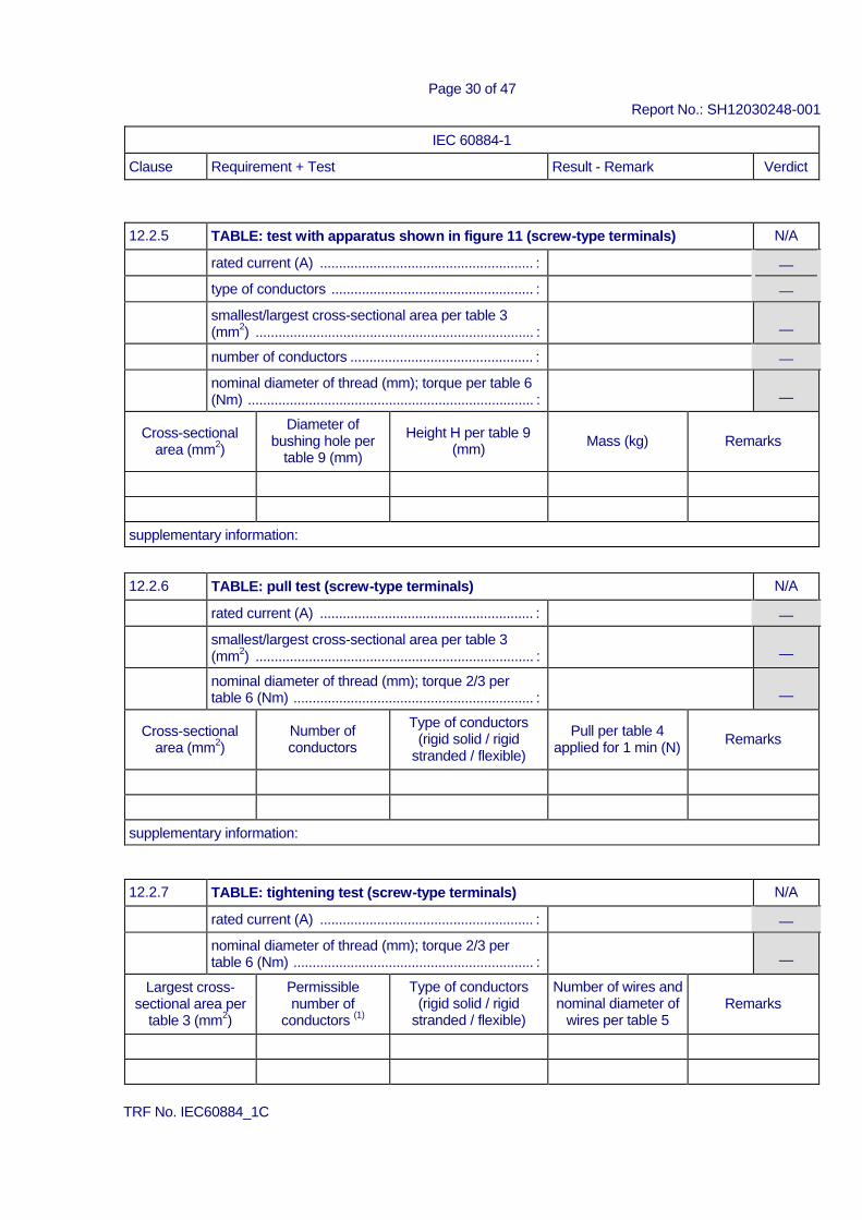
12.2.5 TABLE: test with apparatus shown in figure 11 (screw-type terminals) N/A rated current (A) ........................................................ : ⎯ type of conductors ..................................................... : ⎯ smallest/largest cross-sectional area per table 3
(mm2) ......................................................................... :
⎯ number of conductors ................................................ : ⎯ nominal diameter of thread (mm); torque per table 6
(Nm) ........................................................................... :
⎯
Cross-sectional area (mm2)
Diameter of bushing hole per
table 9 (mm)
Height H per table 9
(mm)
Mass (kg)
Remarks
supplementary information:
12.2.6 TABLE: pull test (screw-type terminals) N/A rated current (A) ........................................................ : ⎯ smallest/largest cross-sectional area per table 3
(mm2) ......................................................................... :
⎯ nominal diameter of thread (mm); torque 2/3 per
table 6 (Nm) ............................................................... :
⎯
Cross-sectional area (mm2)
Number of conductors
Type of conductors (rigid solid / rigid
stranded / flexible)
Pull per table 4
applied for 1 min (N)
Remarks
supplementary information:
12.2.7 TABLE: tightening test (screw-type terminals) N/A rated current (A) ........................................................ : ⎯ nominal diameter of thread (mm); torque 2/3 per
table 6 (Nm) ............................................................... :
⎯ Largest cross-
sectional area per table 3 (mm2)
Permissible number of
conductors (1)
Type of conductors (rigid solid / rigid
stranded / flexible)
Number of wires and nominal diameter of
wires per table 5
Remarks
TRF No. IEC60884_1C
Page 31 of 47 Report No.: SH12030248-001
IEC 60884-1 Clause Requirement + Test Result - Remark Verdict
supplementary information: (1) terminals intended for looping-in 2 or 3 conductors
12.3.10 TABLE: mechanical strength test (screwless-type terminals) N/A rated current (A) ........................................................ : ⎯ largest/smallest cross-sectional area per table 7
(mm2) ......................................................................... :
⎯ Number of connection (after that
conductor subjected to a pull of 30 N for 1 min) / disconnection
Type of conductor (solid / rigid stranded / flexible
Cross-sectional area (mm2)
Remarks
TABLE: test with apparatus shown in figure 11 Cross-sectional
area (mm2) Type of conductor
(solid / rigid stranded / flexible
Diameter of bushing hole
per table 9 (mm)
Height H per table
9 (mm)
Mass (kg)
Remarks
supplementary information:
12.3.11 TABLE: electrical and thermal strength test (screwless-type terminals) N/A Test a) Test carried out for 1 h connecting rigid solid conductors: test current per table 10 (A) ...................................... : ⎯ nominal cross-sectional area (mm2) ......................... : ⎯
Screwless terminal number Voltage drop (mV) Required voltage drop (mV) Test b) Temperature cycles test carried out on terminals subjected to Test a): test current per table 10 (A) ...................................... : ⎯ nominal cross-sectional area (mm2) ......................... : ⎯ allowed voltage drop (mV) ........................................ : ⎯ Screwless terminal number 1 2 3 4 5 Remarks 12.3.10 TABLE: mechanical strength test (screwless-type terminals)
TRF No. IEC60884_1C
Page 32 of 47 Report No.: SH12030248-001
IEC 60884-1 Clause Requirement + Test Result - Remark Verdict
rated current (A) ........................................................ : ⎯ largest/smallest cross-sectional area per table 7
(mm2) ......................................................................... :
⎯ Number of connection (after that
conductor subjected to a pull of 30 N for 1 min) / disconnection
Type of conductor (solid / rigid stranded / flexible
Cross-sectional area (mm2)
Remarks
TABLE: test with apparatus shown in figure 11 Cross-sectional
area (mm2) Type of conductor
(solid / rigid stranded / flexible
Diameter of bushing hole
per table 9 (mm)
Height H per table
9 (mm)
Mass (kg)
Remarks
supplementary information:
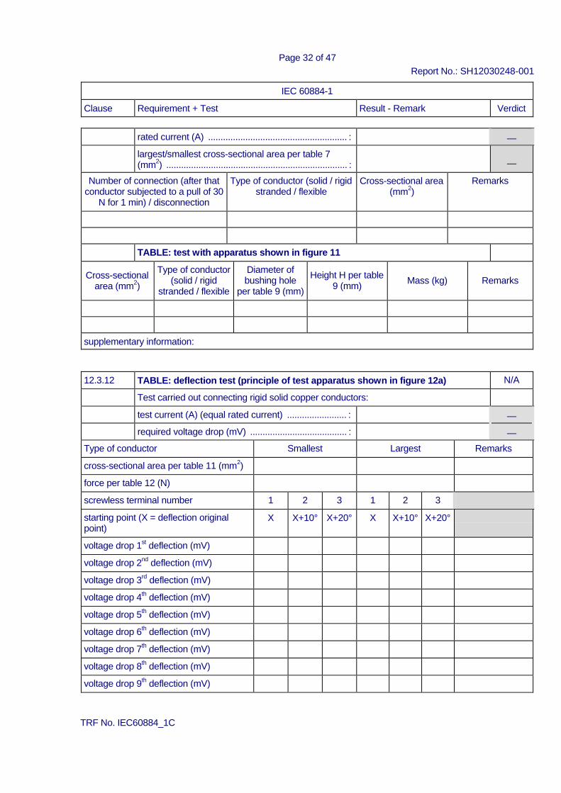
12.3.12 TABLE: deflection test (principle of test apparatus shown in figure 12a) N/A Test carried out connecting rigid solid copper conductors: test current (A) (equal rated current) ........................ : ⎯ required voltage drop (mV) ....................................... : ⎯ Type of conductor Smallest Largest Remarks cross-sectional area per table 11 (mm2) force per table 12 (N) screwless terminal number 1 2 3 1 2 3 starting point (X = deflection original point)
X X+10° X+20° X X+10° X+20°
voltage drop 1st deflection (mV) voltage drop 2nd deflection (mV) voltage drop 3rd deflection (mV) voltage drop 4th deflection (mV) voltage drop 5th deflection (mV) voltage drop 6th deflection (mV) voltage drop 7th deflection (mV) voltage drop 8th deflection (mV) voltage drop 9th deflection (mV)
TRF No. IEC60884_1C
Page 33 of 47 Report No.: SH12030248-001
IEC 60884-1 Clause Requirement + Test Result - Remark Verdict
voltage drop 10th deflection (mV) voltage drop 11th deflection (mV) voltage drop 12th deflection (mV) supplementary information:
17.1 TABLE: insulation resistance P Item per
17.1 test voltage applied between: measured (MΩ) required (MΩ)
a) between all poles connected together and the body 199 ≥5 b) between each pole in turn and all others connected
to the body
199 ≥5 supplementary information:
17.2 TABLE: electric strength P rated voltage (V) ........................................................ : 250V~ ⎯
item per 17.1
test voltage applied between:
test voltage (V)
flashover / breakdown (Yes/No)
a) between all poles connected together and the body 2000 No b) between each pole in turn and all others connected
to the body
2000
No
supplementary information:
19 TABLE: temperature rise test P rated current of accessory (A) .................................. : 16A ⎯ type of accessory (non-rewirable / rewirable) .......... : Non-rewirable ⎯ nominal cross-sectional area per table 15 (mm2)
(rewirable accessories) / type of conductor .............. : 0,75mm2/1,0mm2 H05VV-F (The test for 1,5mm2 cord covered by 1,0mm2); ⎯
type of conductors (rigid solid / rigid stranded / flexible) (rewirable accessories) ............................... :
⎯
nominal diameter of thread (mm); torque 2/3 of that specified in 12.2.8 (Nm) (rewirable accessories) .... :
⎯
TRF No. IEC60884_1C
Page 34 of 47 Report No.: SH12030248-001
IEC 60884-1 Clause Requirement + Test Result - Remark Verdict
specimen
type of flexible cable (1)
number of
conductors and nominal cross- sectional area
(mm2) (1)
test circuit (L-L/L-N/L-E)
test
current (table 20)
for 1 h (A)
measured dT (K)
allowed dT (K)
temperature rise of
external parts of insulating
material (25.3)
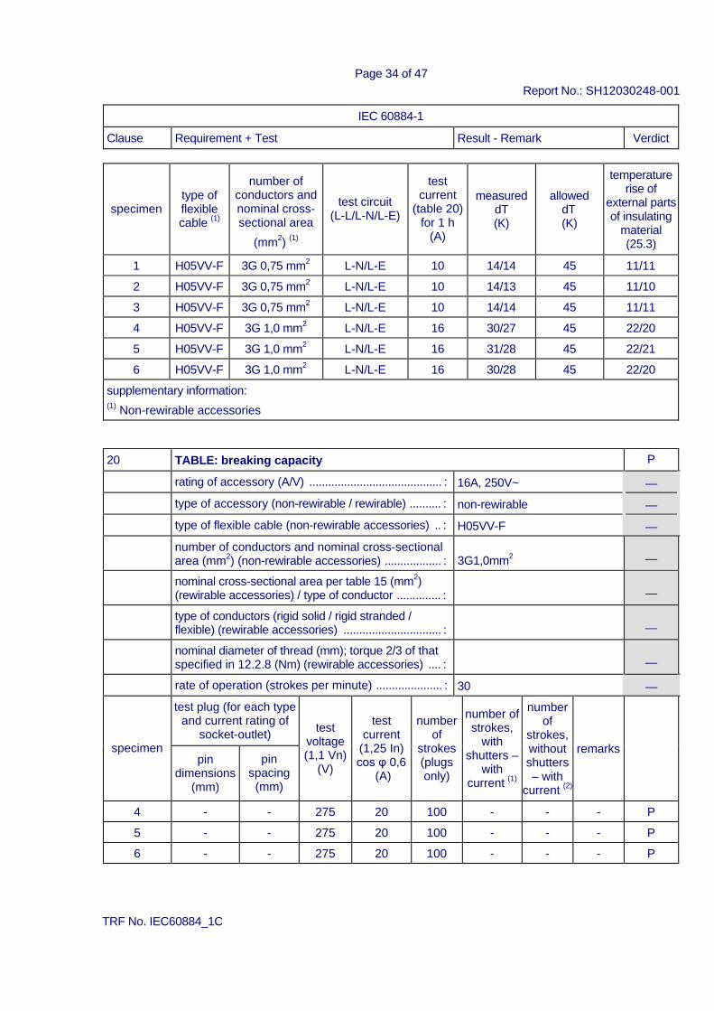
1 H05VV-F 3G 0,75 mm2 L-N/L-E 10 14/14 45 11/11 2 H05VV-F 3G 0,75 mm2 L-N/L-E 10 14/13 45 11/10 3 H05VV-F 3G 0,75 mm2 L-N/L-E 10 14/14 45 11/11 4 H05VV-F 3G 1,0 mm2 L-N/L-E 16 30/27 45 22/20 5 H05VV-F 3G 1,0 mm2 L-N/L-E 16 31/28 45 22/21 6 H05VV-F 3G 1,0 mm2 L-N/L-E 16 30/28 45 22/20
supplementary information: (1) Non-rewirable accessories
20 TABLE: breaking capacity P rating of accessory (A/V) .......................................... : 16A, 250V~ ⎯ type of accessory (non-rewirable / rewirable) .......... : non-rewirable ⎯ type of flexible cable (non-rewirable accessories) .. : H05VV-F ⎯ number of conductors and nominal cross-sectional
area (mm2) (non-rewirable accessories) .................. : 3G1,0mm2 ⎯
nominal cross-sectional area per table 15 (mm2) (rewirable accessories) / type of conductor .............. :
⎯
type of conductors (rigid solid / rigid stranded / flexible) (rewirable accessories) ............................... :
⎯
nominal diameter of thread (mm); torque 2/3 of that specified in 12.2.8 (Nm) (rewirable accessories) .... :
⎯
rate of operation (strokes per minute) ..................... : 30 ⎯
specimen
test plug (for each type and current rating of
socket-outlet)
test voltage (1,1 Vn)
(V)
test
current (1,25 In) cos φ 0,6
(A)
number
of strokes (plugs only)
number of strokes,
with shutters –
with current (1)
number of
strokes, without shutters – with
current (2)
remarks
pin dimensions
(mm)
pin spacing
(mm)
4 - - 275 20 100 - - - P 5 - - 275 20 100 - - - P 6 - - 275 20 100 - - - P
TRF No. IEC60884_1C
Page 35 of 47 Report No.: SH12030248-001
IEC 60884-1 Clause Requirement + Test Result - Remark Verdict
supplementary information: (1) starting point 1 or 3 of Figure 43 (2) starting point 2 of Figure 43
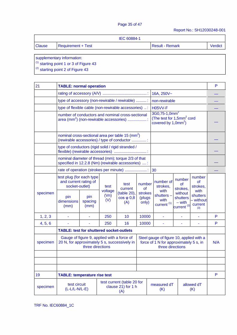
21 TABLE: normal operation P rating of accessory (A/V) .......................................... : 16A, 250V~ ⎯ type of accessory (non-rewirable / rewirable) .......... : non-rewirable ⎯ type of flexible cable (non-rewirable accessories) .. : H05VV-F ⎯ number of conductors and nominal cross-sectional
area (mm2) (non-rewirable accessories) .................. : 3G0,75-1,0mm2
(The test for 1,5mm2 cord covered by 1,0mm2) ⎯
nominal cross-sectional area per table 15 (mm2) (rewirable accessories) / type of conductor .............. :
⎯
type of conductors (rigid solid / rigid stranded / flexible) (rewirable accessories) ............................... :
⎯
nominal diameter of thread (mm); torque 2/3 of that specified in 12.2.8 (Nm) (rewirable accessories) .... :
⎯
rate of operation (strokes per minute) ..................... : 30 ⎯
specimen
test plug (for each type and current rating of
socket-outlet)
test voltage
(Vn) (V)
test current
(table 20), cos φ 0,8
(A)
number
of strokes (plugs only)
number of strokes,
with shutters –
with current (1)
number
of strokes, without shutters – with
current (2)
number of
strokes, with
shutters – without current
(3)
pin
dimensions (mm)
pin
spacing (mm)
1, 2, 3 - - 250 10 10000 - - - P 4, 5, 6 - - 250 16 10000 - - - P
TABLE: test for shuttered socket-outlets
specimen Gauge of figure 9, applied with a force of
20 N, for approximately 5 s, successively in three directions
Steel gauge of figure 10, applied with a force of 1 N for approximately 5 s, in
three directions
N/A
19 TABLE: temperature rise test P
specimen
test circuit (L-L/L-N/L-E)
test current (table 20 for clause 21) for 1 h
(A)
measured dT
(K)
allowed dT
(K)
TRF No. IEC60884_1C
Page 36 of 47 Report No.: SH12030248-001
IEC 60884-1 Clause Requirement + Test Result - Remark Verdict
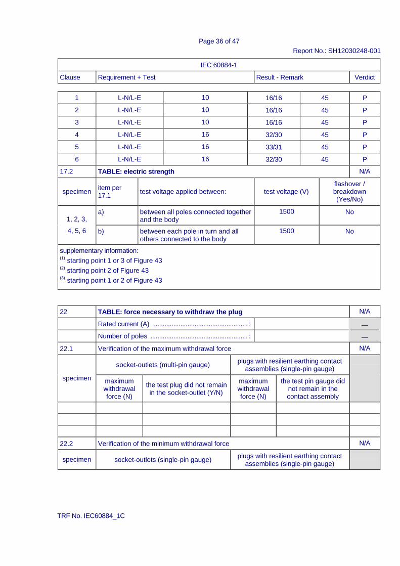
1 L-N/L-E 10 16/16 45 P 2 L-N/L-E 10 16/16 45 P 3 L-N/L-E 10 16/16 45 P 4 L-N/L-E 16 32/30 45 P 5 L-N/L-E 16 33/31 45 P 6 L-N/L-E 16 32/30 45 P
17.2 TABLE: electric strength N/A
specimen item per 17.1
test voltage applied between:
test voltage (V)
flashover / breakdown (Yes/No)
1, 2, 3,
4, 5, 6
a) between all poles connected together and the body
1500 No
b) between each pole in turn and all others connected to the body
1500 No
supplementary information: (1) starting point 1 or 3 of Figure 43 (2) starting point 2 of Figure 43 (3) starting point 1 or 2 of Figure 43
22 TABLE: force necessary to withdraw the plug N/A Rated current (A) ...................................................... : ⎯ Number of poles ....................................................... : ⎯ 22.1 Verification of the maximum withdrawal force N/A
specimen
socket-outlets (multi-pin gauge) plugs with resilient earthing contact
assemblies (single-pin gauge)
maximum withdrawal force (N)
the test plug did not remain in the socket-outlet (Y/N)
maximum withdrawal force (N)
the test pin gauge did not remain in the contact assembly
22.2 Verification of the minimum withdrawal force N/A
specimen
socket-outlets (single-pin gauge) plugs with resilient earthing contact
assemblies (single-pin gauge)
TRF No. IEC60884_1C
Page 37 of 47 Report No.: SH12030248-001
IEC 60884-1 Clause Requirement + Test Result - Remark Verdict
minimum withdrawal force (N)
the test pin gauge did not fall from each individual
contact-assembly within 30 s (Y/N)
minimum
withdrawal force (N)
the test pin gauge did not fall from each individual earthing contact-assembly within 30 s (Y/N)
supplementary information:
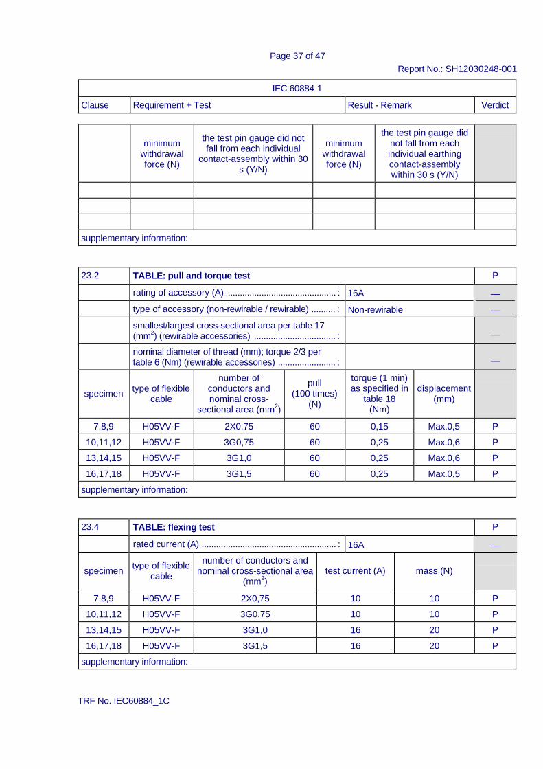
23.2 TABLE: pull and torque test P rating of accessory (A) ............................................. : 16A ⎯ type of accessory (non-rewirable / rewirable) .......... : Non-rewirable ⎯ smallest/largest cross-sectional area per table 17
(mm2) (rewirable accessories) .................................. :
⎯ nominal diameter of thread (mm); torque 2/3 per
table 6 (Nm) (rewirable accessories) ........................ :
⎯
specimen type of flexible
cable
number of conductors and nominal cross-
sectional area (mm2)
pull
(100 times) (N)
torque (1 min) as specified in
table 18 (Nm)
displacement
(mm)
7,8,9 H05VV-F 2X0,75 60 0,15 Max.0,5 P 10,11,12 H05VV-F 3G0,75 60 0,25 Max.0,6 P 13,14,15 H05VV-F 3G1,0 60 0,25 Max.0,6 P 16,17,18 H05VV-F 3G1,5 60 0,25 Max.0,5 P
supplementary information:
23.4 TABLE: flexing test P rated current (A) ........................................................ : 16A ⎯
specimen type of flexible
cable number of conductors and
nominal cross-sectional area (mm2)
test current (A)
mass (N)
7,8,9 H05VV-F 2X0,75 10 10 P 10,11,12 H05VV-F 3G0,75 10 10 P 13,14,15 H05VV-F 3G1,0 16 20 P 16,17,18 H05VV-F 3G1,5 16 20 P
supplementary information:
TRF No. IEC60884_1C
Page 38 of 47 Report No.: SH12030248-001
IEC 60884-1 Clause Requirement + Test Result - Remark Verdict
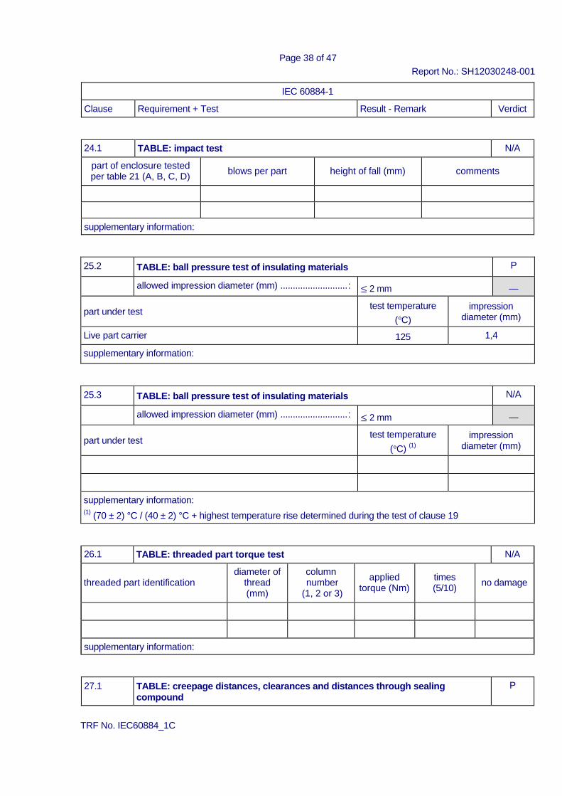
24.1 TABLE: impact test N/A part of enclosure tested per table 21 (A, B, C, D)
blows per part
height of fall (mm)
comments
supplementary information:
25.2 TABLE: ball pressure test of insulating materials P
allowed impression diameter (mm) ...........................: ≤ 2 mm ⎯ part under test test temperature
(°C) impression
diameter (mm) Live part carrier 125 1,4 supplementary information:
25.3 TABLE: ball pressure test of insulating materials N/A
allowed impression diameter (mm) ...........................: ≤ 2 mm ⎯ part under test test temperature
(°C) (1) impression
diameter (mm)
supplementary information: (1) (70 ± 2) °C / (40 ± 2) °C + highest temperature rise determined during the test of clause 19
26.1 TABLE: threaded part torque test N/A threaded part identification
diameter of thread (mm)
column number
(1, 2 or 3)
applied
torque (Nm)
times (5/10)
no damage
supplementary information:
27.1 TABLE: creepage distances, clearances and distances through sealing compound
P
TRF No. IEC60884_1C
Page 39 of 47 Report No.: SH12030248-001
IEC 60884-1 Clause Requirement + Test Result - Remark Verdict
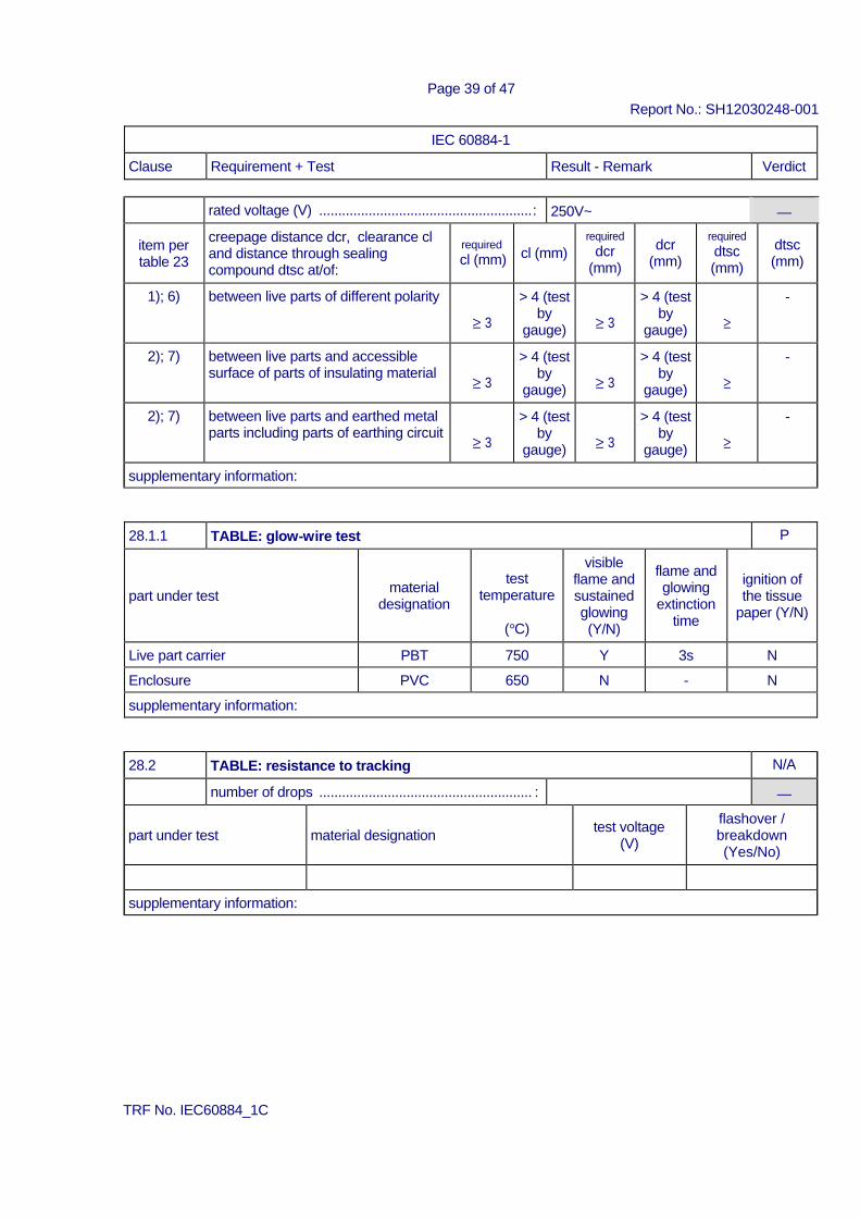
rated voltage (V) ........................................................: 250V~ ⎯
item per table 23
creepage distance dcr, clearance cl and distance through sealing compound dtsc at/of:
required cl (mm)
cl (mm)
required dcr
(mm)
dcr
(mm) required dtsc (mm)
dtsc (mm)
1); 6) between live parts of different polarity ≥ 3
> 4 (test by
gauge) ≥ 3 > 4 (test
by gauge) ≥
-
2); 7) between live parts and accessible surface of parts of insulating material
≥ 3 > 4 (test
by gauge) ≥ 3
> 4 (test by
gauge) ≥ -
2); 7) between live parts and earthed metal parts including parts of earthing circuit
≥ 3 > 4 (test
by gauge) ≥ 3
> 4 (test by
gauge) ≥ -
supplementary information:
28.1.1 TABLE: glow-wire test P part under test
material designation
test
temperature
(°C)
visible flame and sustained glowing (Y/N)
flame and glowing
extinction time
ignition of the tissue
paper (Y/N)
Live part carrier PBT 750 Y 3s N Enclosure PVC 650 N - N supplementary information:
28.2 TABLE: resistance to tracking N/A number of drops ........................................................ : ⎯ part under test
material designation
test voltage
(V) flashover / breakdown (Yes/No)
supplementary information:
TRF No. IEC60884_1C
Page 40 of 47 Report No.: SH12030248-001
Annex A Additional requirements and test according to SANS 164-1:2007 (The clause No in brackets refers to SANS 164-1 standard sheet 1-2)
Clause ANNEX Special tests according to SANS 164-1 Standard Sheet 1-2
9 (8a)
DIMENSIONS Compliance with appropriate Standard Sheet checked by Means of gauges and by measurement, see below
10,0max 8,9
6,8max N/A
21,1±0,6 21,2
2,75±0,75 3,10
29,0±0,6 28,8
3,35±1,00 3,45
Φ8,7±0,0 4
8,68
Φ7,05±0, 04
7,06
9.5 min 9,6
Comments: all applicable dimensions comply with the standard sheet.
TRF No. IEC60884_1C
Page 41 of 47 Report No.: SH12030248-001
Annex B Additional requirement according to Standard SANS 164-0:2007
SANS 164-0 Clause Requirement + Test Result - Remark Verdict 4 Requirements 4.1 General 4.1.1 Plugs, socket-outlets and socket-outlet adaptors
shall comply with the appropriate requirements of SANS 60884-1, and the relevant of SANS 60884-2- 2, SANS 60884-2-3, SANS 60884-2-4, SANS 60884-2-5, and SANS 60884-2-6.
P
4.1.2 Socket-outlets shall comply with the requirements for increased protection of SANS 60884-1.
N/A
4.1.3 A socket-outlet for a fixed installation shall have an earthing contact. A multiple socket-outlet for a fixed installation shall have at least one socket-outlet with an earthing contact.
N/A
4.1.4 A dedicated plug shall comply with all relevant requirements of all parts of SANS 60884 when used in combination with both a dedicated socket- outlet (SANS 164-4) and a conventional socket- outlet (SANS 164-1), and a conventional socket- outlet shall comply with all relevant requirements of all parts of SANS 60884 when used in combination with both a conventional plug and a dedicated plug.
N/A
4.1.5 The earth contact of a dedicated socket-outlet shall withstand a torque of 2,6 Nm for one minute in a clockwise direction and then for one minute in an anti-clockwise direction, the torque being applied using a D-shaped earthpin.
N/A
4.1.6 A surge protection device (SPD) incorporated in a plug, in an adaptor or in a portable socketoutlet shall comply with the requirements of SANS 61643- 1, with special attention to the temporary overvoltage (TOV) requirements. An SPD without an internal disconnecting mechanism shall only be fitted between line and earth and between neutral and earth, and not between line and neutral. SPDs without internal disconnecting mechanisms shall not be fitted to dedicated plug and socketoutlet systems.
N/A
Fixed socket-outlets fall within the scope of SANS 10142-1, and incorporated SPDs are covered in that standard.
N/A
4.2 Dimensions 4.2.1 The dimensions of a plug shall comply with the plug
dimensions given in one of the following: P
SANS 164-1, SANS 164-2, SANS 164-3, SANS 164-4, SANS 164-5, SANS 164-6, or SANS 60906- 3.
Plug comply with SANS 164-1 P
TRF No. IEC60884_1C
Page 42 of 47 Report No.: SH12030248-001
SANS 164-0 Clause Requirement + Test Result - Remark Verdict 4.2.2 The dimensions of a socket-outlet shall comply with
the socket-outlet dimensions of one of the following:
N/A
SANS 164-1, SANS 164-2, SANS 164-3, SANS 164-4, SANS 164-6 or SANS 60906-3.
N/A
4.2.3 The plug of an adaptor shall comply with the dimensions of SANS 164-1 or SANS 164-2. The earthpin of an adaptor may be of insulation material, provided the adaptor does not include a socket-outlet that will accept a plug with an earthpin. (See also 4.2.5.)
N/A
4.2.4 The socket-outlets of an adaptor shall comply with the socket-outlet dimensions of one or more of SANS 164-1, SANS 164-2, SANS 164-3 or SANS 164-6. (See also 4.2.5.)
N/A
4.2.5 The pins of an adaptor may comply with the dimensions of SANS 164-4, provided all the socket contacts are of the same dedicated type, i.e. no adapting from a dedicated socket-outlet to a non- dedicated socket-outlet, or to another type of dedicated socket-outlet, is permitted.
N/A
4.2.6 An adaptor shall not fit into a lampholder. N/A 4.2.7 The means of mounting a fixed socket-outlet in a
wall outlet box shall permit rotational adjustment of the socket-outlet relative to the box through an angle of at least 10°.
N/A
4.2.8 A socket-outlet for fixed installation, which is not supplied with its own outlet box, shall have mounting centres that comply with SANS 1085.
N/A
4.3 Rating The voltage and current ratings of an accessory
shall comply with the requirements of the relevant of SANS 164-1, SANS 164-2, SANS 164-3, SANS 164-4, SANS 164-5, SANS 164-6, or SANS 60906- 3.
Comply with SANS 164-1 P
TRF No. IEC60884_1C
Page 43 of 47 Report No.: SH12030248-001
Annex C Additional requirement according to Standard SANS 164-1:2007
SANS 164-1 Clause Requirement + Test Result - Remark Verdict 4 Requirements 4.1 The requirements of SANS 164-0 apply. P 4.2 Socket-outlets, socket-outlet adaptors and rewirable
plugs shall be rated at 16A and 250Va.c. N/A
4.3 Plugs and socket-outlets shall comply with the dimensions given on the appropriate of standard sheets 1-1 or 1-2.
comply with standard sheet 1-2 P
Use the gauges given in annexes A to F for checking the dimensions.
P
TRF No. IEC60884_1C
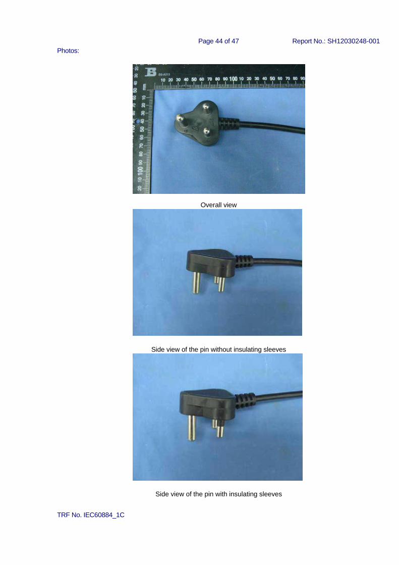
Page 44 of 47 Report No.: SH12030248-001 Photos:
Overall view
Side view of the pin without insulating sleeves
Side view of the pin with insulating sleeves
TRF No. IEC60884_1C
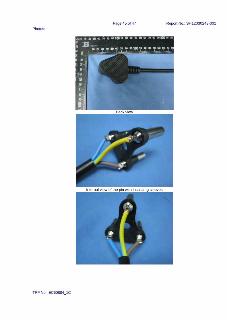
Page 45 of 47 Report No.: SH12030248-001 Photos:
Back view
Internal view of the pin with insulating sleeves
TRF No. IEC60884_1C
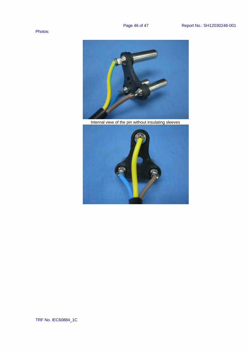
Page 46 of 47 Report No.: SH12030248-001 Photos:
Internal view of the pin without insulating sleeves
TRF No. IEC60884_1C
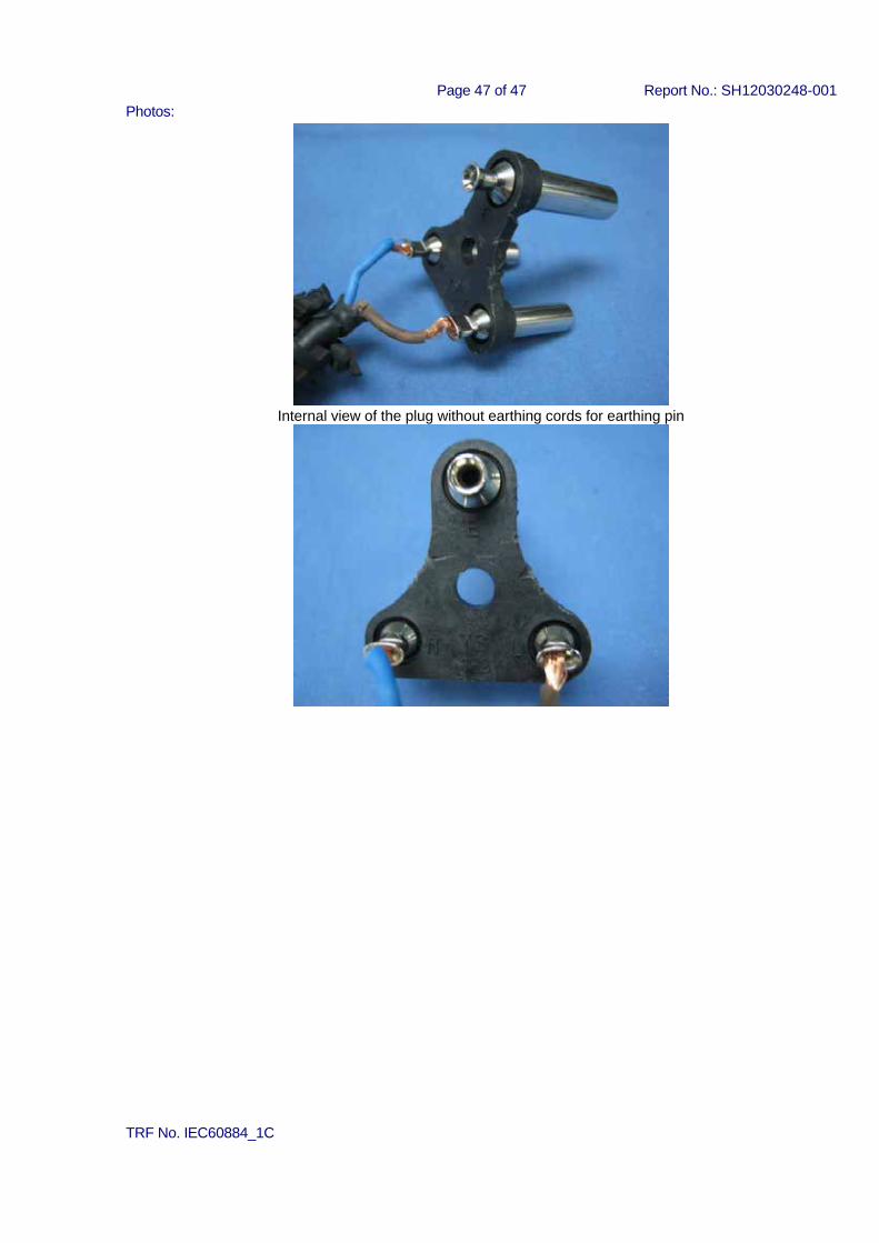
Page 47 of 47 Report No.: SH12030248-001 Photos:
Internal view of the plug without earthing cords for earthing pin
TRF No. IEC60884_1C