Embed Size (px)
Citation preview
Registration
No.788871
TEST REPORT FOR BLUETOOTH
TESTING
Report No: SRTC2018-9004(F)-18020601(D)
Product Name: OnePlus Bullets Wireless
Product Model: BT31B
Applicant: OnePlus Technology (Shenzhen) Co., Ltd.
Manufacturer: OnePlus Technology (Shenzhen) Co., Ltd.
Specification: FCC Part 15, Subpart C (2017)
FCC ID: 2ABZ2-BT31B
The State Radio_monitoring_center Testing Center (SRTC)
15th Building, No.30, Shixing Street, Shijingshan District,
Beijing, P.R.China
Tel: 86-10-57996183 Fax: 86-10-57996388
No.: SRTC2018-9004(F)-18020601(D) FCC ID: 2ABZ2-BT31B
The State Radio_monitoring_center Testing Center (SRTC) Page number: 1 of 65
Tel: 86-10-5799 6183 Fax: 86-10-57996388 20170915V1.0.0
CONTENTS
1. GENERAL INFORMATION .................................................................................................................................... 2
1.1 NOTES OF THE TEST REPORT .................................................................................................................................... 2
1.2 INFORMATION ABOUT THE TESTING LABORATORY ..................................................................................................... 2
1.3 APPLICANT’S DETAILS ................................................................................................................................................ 2
1.4 MANUFACTURER’S DETAILS ....................................................................................................................................... 2
1.5 TEST ENVIRONMENT .................................................................................................................................................. 3
2 DESCRIPTION OF THE DEVICE UNDER TEST .................................................................................................. 4
2.1 FINAL EQUIPMENT BUILD STATUS ............................................................................................................................. 4
2.2 DESCRIPTION OF TEST MODES ................................................................................................................................ 5
2.2.1 TEST MODE APPLICABILITY AND TESTED CHANNEL DETAIL ................................................................................. 5
2.3 DUTY CYCLE OF TEST SIGNAL ................................................................................................................................. 7
2.4 EUT OPERATING CONDITIONS ................................................................................................................................... 7
2.5 SUPPORT EQUIPMENT................................................................................................................................................ 7
3 REFERENCE SPECIFICATION ............................................................................................................................. 8
4 KEY TO NOTES AND RESULT CODES ............................................................................................................... 9
5 RESULT SUMMARY ............................................................................................................................................. 10
6 TEST RESULT ....................................................................................................................................................... 11
6.1 OCCUPIED BANDWIDTH............................................................................................................................................ 11
6.2 CHANNEL SEPARATION ............................................................................................................................................ 12
6.3 OUTPUT POWER ...................................................................................................................................................... 13
6.4 DWELL TIME ............................................................................................................................................................. 14
6.5 NUMBER OF HOPPING FREQUENCIES...................................................................................................................... 16
6.6 CONDUCTED OUT OF BAND EMISSION MEASUREMENT ............................................................................................ 17
6.7 BAND-EDGE MEASUREMENT .................................................................................................................................... 18
6.8 SPURIOUS RADIATED EMISSIONS ............................................................................................................................ 19
6.9 AC POWER LINE CONDUCTED EMISSION ................................................................................................................ 24
7 MEASUREMENT UNCERTAINTIES ................................................................................................................... 26
8 TEST EQUIPMENTS ............................................................................................................................................. 27
APPENDIX A – TEST DATA OF CONDUCTED EMISSION ................................................................................ 28
CHANNEL SEPARATION .................................................................................................................................................. 34
PEAK POWER OUTPUT ................................................................................................................................................... 35
DWELL TIME ................................................................................................................................................................... 36
NUMBER OF HOPPING FREQUENCIES ............................................................................................................................ 42
CONDUCTED OUT OF BAND EMISSION MEASUREMENT................................................................................................... 43
BAND EDGE MEASUREMENT ........................................................................................................................................... 46
APPENDIX B – TEST DATA OF RADIATED EMISSION ...................................................................................... 49
No.: SRTC2018-9004(F)-18020601(D) FCC ID: 2ABZ2-BT31B
The State Radio_monitoring_center Testing Center (SRTC) Page number: 2 of 65
Tel: 86-10-5799 6183 Fax: 86-10-57996388 20170915V1.0.0
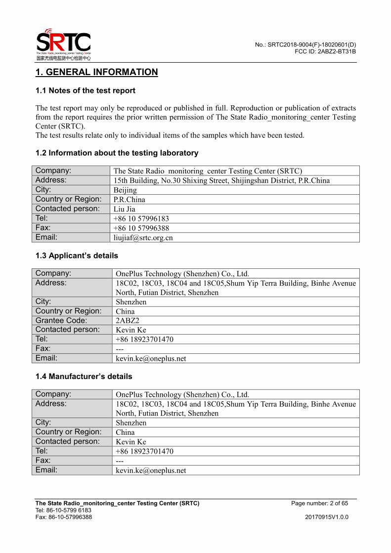
1. GENERAL INFORMATION
1.1 Notes of the test report
The test report may only be reproduced or published in full. Reproduction or publication of extracts
from the report requires the prior written permission of The State Radio_monitoring_center Testing
Center (SRTC).
The test results relate only to individual items of the samples which have been tested.
1.2 Information about the testing laboratory
Company: The State Radio_monitoring_center Testing Center (SRTC)
Address: 15th Building, No.30 Shixing Street, Shijingshan District, P.R.China
City: Beijing
Country or Region: P.R.China
Contacted person: Liu Jia
Tel: +86 10 57996183
Fax: +86 10 57996388
Email: [email protected]
1.3 Applicant’s details
Company: OnePlus Technology (Shenzhen) Co., Ltd.
Address: 18C02, 18C03, 18C04 and 18C05,Shum Yip Terra Building, Binhe Avenue
North, Futian District, Shenzhen
City: Shenzhen
Country or Region: China
Grantee Code: 2ABZ2 Contacted person: Kevin Ke
Tel: +86 18923701470
Fax: ---
Email: [email protected]
1.4 Manufacturer’s details
Company: OnePlus Technology (Shenzhen) Co., Ltd.
Address: 18C02, 18C03, 18C04 and 18C05,Shum Yip Terra Building, Binhe Avenue
North, Futian District, Shenzhen
City: Shenzhen
Country or Region: China
Contacted person: Kevin Ke
Tel: +86 18923701470
Fax: ---
Email: [email protected]

No.: SRTC2018-9004(F)-18020601(D) FCC ID: 2ABZ2-BT31B
The State Radio_monitoring_center Testing Center (SRTC) Page number: 3 of 65
Tel: 86-10-5799 6183 Fax: 86-10-57996388 20170915V1.0.0
1.5 Test Environment
Date of Receipt of test sample at SRTC: 2018-02-06
Testing Start Date: 2018-02-26
Testing End Date: 2018-02-28
Environmental Data: Temperature (°C) Humidity (%)
Ambient 22 33
Normal Supply Voltage (V d.c.): 3.70
No.: SRTC2018-9004(F)-18020601(D) FCC ID: 2ABZ2-BT31B
The State Radio_monitoring_center Testing Center (SRTC) Page number: 4 of 65
Tel: 86-10-5799 6183 Fax: 86-10-57996388 20170915V1.0.0
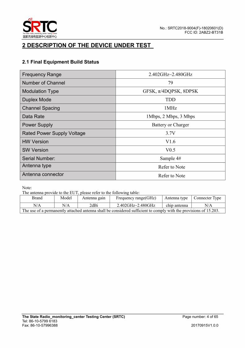
2 DESCRIPTION OF THE DEVICE UNDER TEST
2.1 Final Equipment Build Status
Frequency Range 2.402GHz~2.480GHz
Number of Channel 79
Modulation Type GFSK, π/4DQPSK, 8DPSK
Duplex Mode TDD
Channel Spacing 1MHz
Data Rate 1Mbps, 2 Mbps, 3 Mbps
Power Supply Battery or Charger
Rated Power Supply Voltage 3.7V
HW Version V1.6
SW Version V0.5
Serial Number: Sample 4#
Antenna type Refer to Note
Antenna connector Refer to Note
Note:
The antenna provide to the EUT, please refer to the following table:
Brand Model Antenna gain Frequency range(GHz) Antenna type Connecter Type
N/A N/A 2dBi 2.402GHz~2.480GHz chip antenna N/A
The use of a permanently attached antenna shall be considered sufficient to comply with the provisions of 15.203.
No.: SRTC2018-9004(F)-18020601(D) FCC ID: 2ABZ2-BT31B
The State Radio_monitoring_center Testing Center (SRTC) Page number: 5 of 65
Tel: 86-10-5799 6183 Fax: 86-10-57996388 20170915V1.0.0
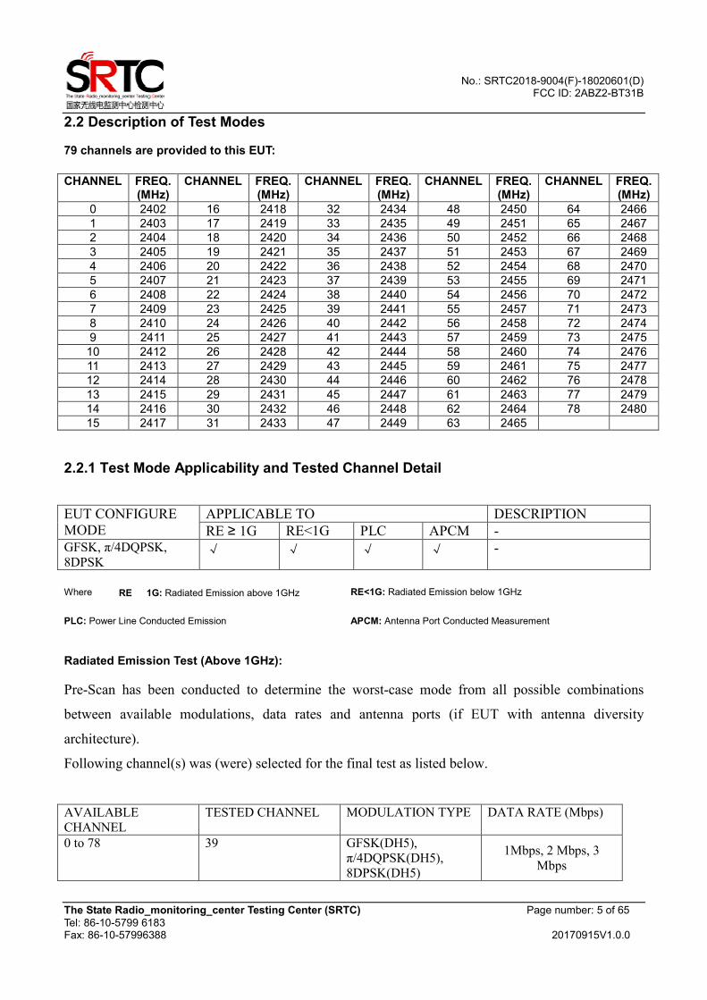
2.2 Description of Test Modes
79 channels are provided to this EUT:
CHANNEL FREQ.
(MHz) CHANNEL FREQ.
(MHz) CHANNEL FREQ.
(MHz) CHANNEL FREQ.
(MHz) CHANNEL FREQ.
(MHz)
0 2402 16 2418 32 2434 48 2450 64 2466
1 2403 17 2419 33 2435 49 2451 65 2467
2 2404 18 2420 34 2436 50 2452 66 2468
3 2405 19 2421 35 2437 51 2453 67 2469
4 2406 20 2422 36 2438 52 2454 68 2470
5 2407 21 2423 37 2439 53 2455 69 2471
6 2408 22 2424 38 2440 54 2456 70 2472
7 2409 23 2425 39 2441 55 2457 71 2473
8 2410 24 2426 40 2442 56 2458 72 2474
9 2411 25 2427 41 2443 57 2459 73 2475
10 2412 26 2428 42 2444 58 2460 74 2476
11 2413 27 2429 43 2445 59 2461 75 2477
12 2414 28 2430 44 2446 60 2462 76 2478
13 2415 29 2431 45 2447 61 2463 77 2479
14 2416 30 2432 46 2448 62 2464 78 2480
15 2417 31 2433 47 2449 63 2465
2.2.1 Test Mode Applicability and Tested Channel Detail
EUT CONFIGURE
MODE
APPLICABLE TO DESCRIPTION
RE ≥ 1G RE<1G PLC APCM -
GFSK, π/4DQPSK,
8DPSK √ √ √ √ -
Where RE 1G: Radiated Emission above 1GHz RE<1G: Radiated Emission below 1GHz
PLC: Power Line Conducted Emission APCM: Antenna Port Conducted Measurement
Radiated Emission Test (Above 1GHz):
Pre-Scan has been conducted to determine the worst-case mode from all possible combinations
between available modulations, data rates and antenna ports (if EUT with antenna diversity
architecture).
Following channel(s) was (were) selected for the final test as listed below.
AVAILABLE
CHANNEL TESTED CHANNEL MODULATION TYPE DATA RATE (Mbps)
0 to 78 39 GFSK(DH5),
π/4DQPSK(DH5),
8DPSK(DH5)
1Mbps, 2 Mbps, 3
Mbps
No.: SRTC2018-9004(F)-18020601(D) FCC ID: 2ABZ2-BT31B
The State Radio_monitoring_center Testing Center (SRTC) Page number: 6 of 65
Tel: 86-10-5799 6183 Fax: 86-10-57996388 20170915V1.0.0
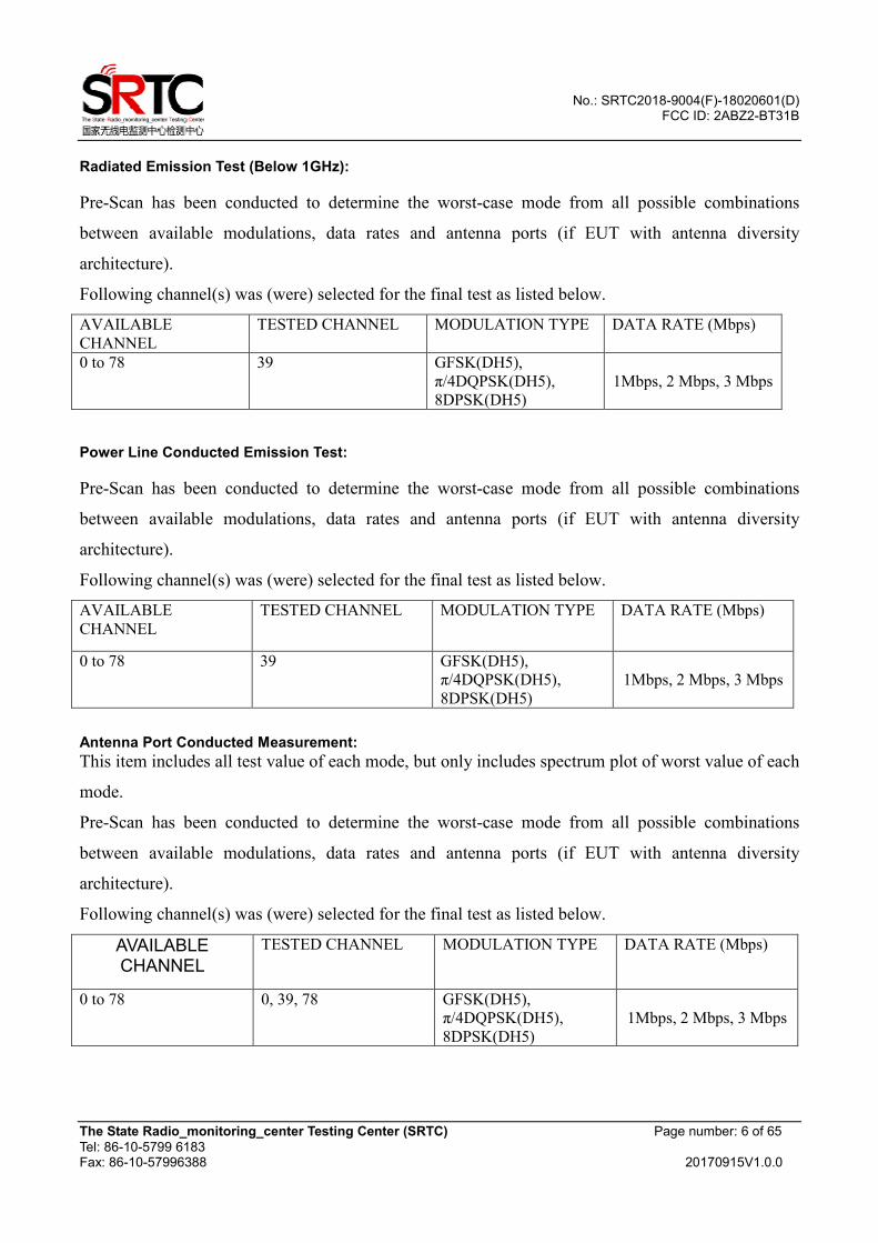
Radiated Emission Test (Below 1GHz):
Pre-Scan has been conducted to determine the worst-case mode from all possible combinations
between available modulations, data rates and antenna ports (if EUT with antenna diversity
architecture).
Following channel(s) was (were) selected for the final test as listed below.
AVAILABLE
CHANNEL
TESTED CHANNEL MODULATION TYPE DATA RATE (Mbps)
0 to 78 39 GFSK(DH5),
π/4DQPSK(DH5),
8DPSK(DH5)
1Mbps, 2 Mbps, 3 Mbps
Power Line Conducted Emission Test:
Pre-Scan has been conducted to determine the worst-case mode from all possible combinations
between available modulations, data rates and antenna ports (if EUT with antenna diversity
architecture).
Following channel(s) was (were) selected for the final test as listed below.
AVAILABLE
CHANNEL
TESTED CHANNEL MODULATION TYPE DATA RATE (Mbps)
0 to 78 39 GFSK(DH5),
π/4DQPSK(DH5),
8DPSK(DH5)
1Mbps, 2 Mbps, 3 Mbps
Antenna Port Conducted Measurement:
This item includes all test value of each mode, but only includes spectrum plot of worst value of each
mode.
Pre-Scan has been conducted to determine the worst-case mode from all possible combinations
between available modulations, data rates and antenna ports (if EUT with antenna diversity
architecture).
Following channel(s) was (were) selected for the final test as listed below.
AVAILABLE CHANNEL
TESTED CHANNEL MODULATION TYPE DATA RATE (Mbps)
0 to 78 0, 39, 78 GFSK(DH5),
π/4DQPSK(DH5),
8DPSK(DH5)
1Mbps, 2 Mbps, 3 Mbps
No.: SRTC2018-9004(F)-18020601(D) FCC ID: 2ABZ2-BT31B
The State Radio_monitoring_center Testing Center (SRTC) Page number: 7 of 65
Tel: 86-10-5799 6183 Fax: 86-10-57996388 20170915V1.0.0
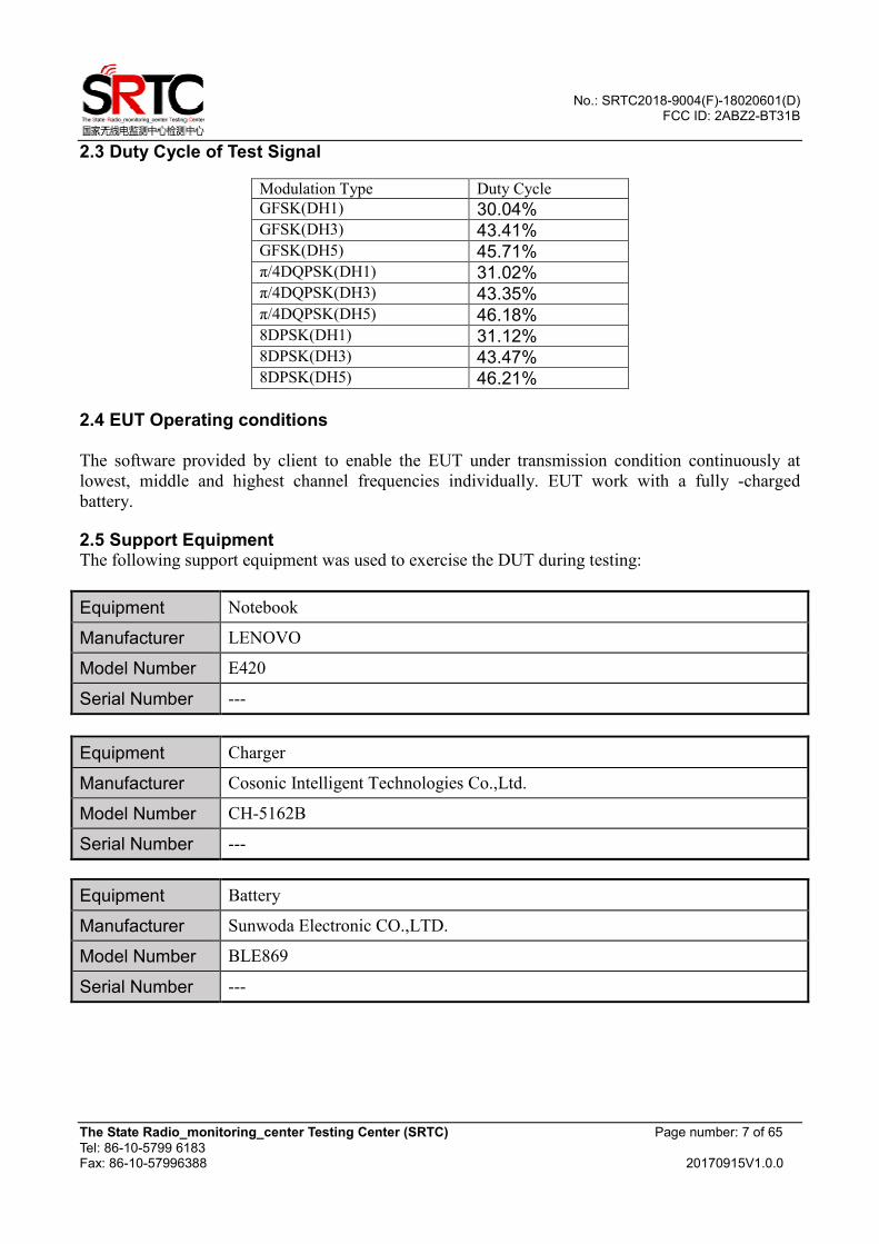
2.3 Duty Cycle of Test Signal
Modulation Type Duty Cycle
GFSK(DH1) 30.04% GFSK(DH3) 43.41% GFSK(DH5) 45.71% π/4DQPSK(DH1) 31.02% π/4DQPSK(DH3) 43.35% π/4DQPSK(DH5) 46.18% 8DPSK(DH1) 31.12% 8DPSK(DH3) 43.47% 8DPSK(DH5) 46.21%
2.4 EUT Operating conditions The software provided by client to enable the EUT under transmission condition continuously at
lowest, middle and highest channel frequencies individually. EUT work with a fully -charged
battery.
2.5 Support Equipment The following support equipment was used to exercise the DUT during testing:
Equipment Notebook
Manufacturer LENOVO
Model Number E420
Serial Number ---
Equipment Charger
Manufacturer Cosonic Intelligent Technologies Co.,Ltd.
Model Number CH-5162B
Serial Number ---
Equipment Battery
Manufacturer Sunwoda Electronic CO.,LTD.
Model Number BLE869
Serial Number ---
No.: SRTC2018-9004(F)-18020601(D) FCC ID: 2ABZ2-BT31B
The State Radio_monitoring_center Testing Center (SRTC) Page number: 8 of 65
Tel: 86-10-5799 6183 Fax: 86-10-57996388 20170915V1.0.0
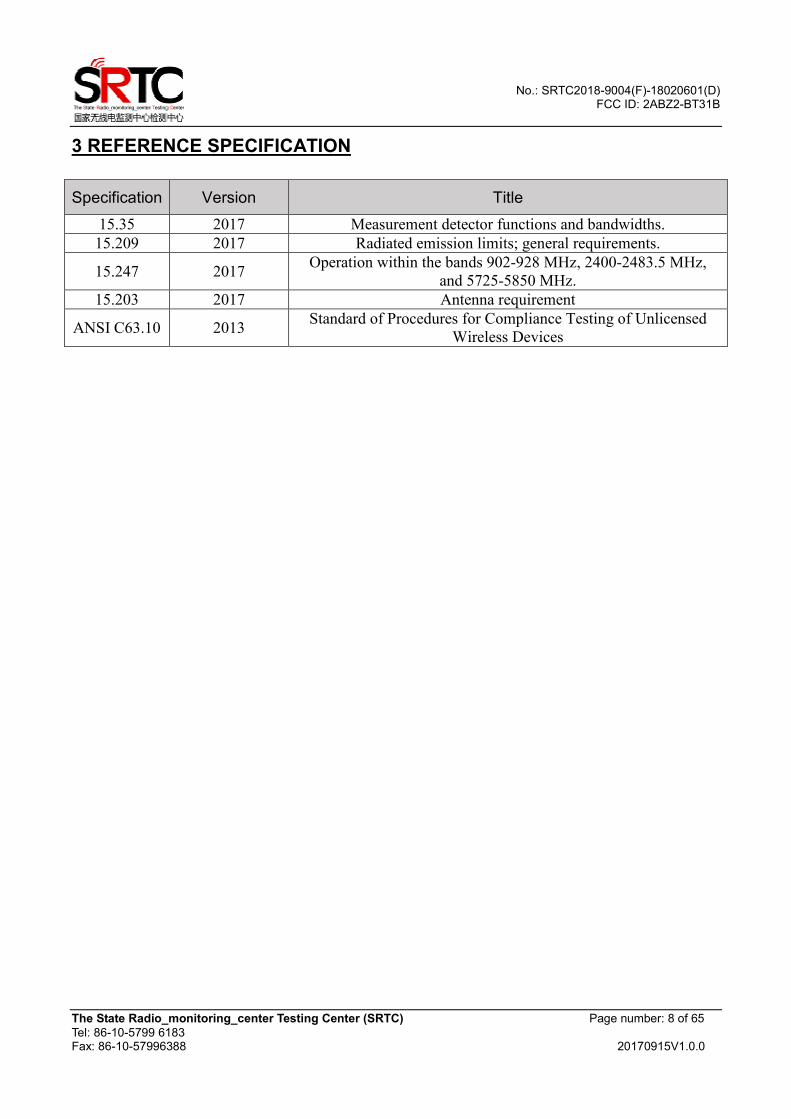
3 REFERENCE SPECIFICATION
Specification Version Title
15.35 2017 Measurement detector functions and bandwidths.
15.209 2017 Radiated emission limits; general requirements.
15.247 2017 Operation within the bands 902-928 MHz, 2400-2483.5 MHz,
and 5725-5850 MHz.
15.203 2017 Antenna requirement
ANSI C63.10 2013 Standard of Procedures for Compliance Testing of Unlicensed
Wireless Devices
No.: SRTC2018-9004(F)-18020601(D) FCC ID: 2ABZ2-BT31B
The State Radio_monitoring_center Testing Center (SRTC) Page number: 9 of 65
Tel: 86-10-5799 6183 Fax: 86-10-57996388 20170915V1.0.0
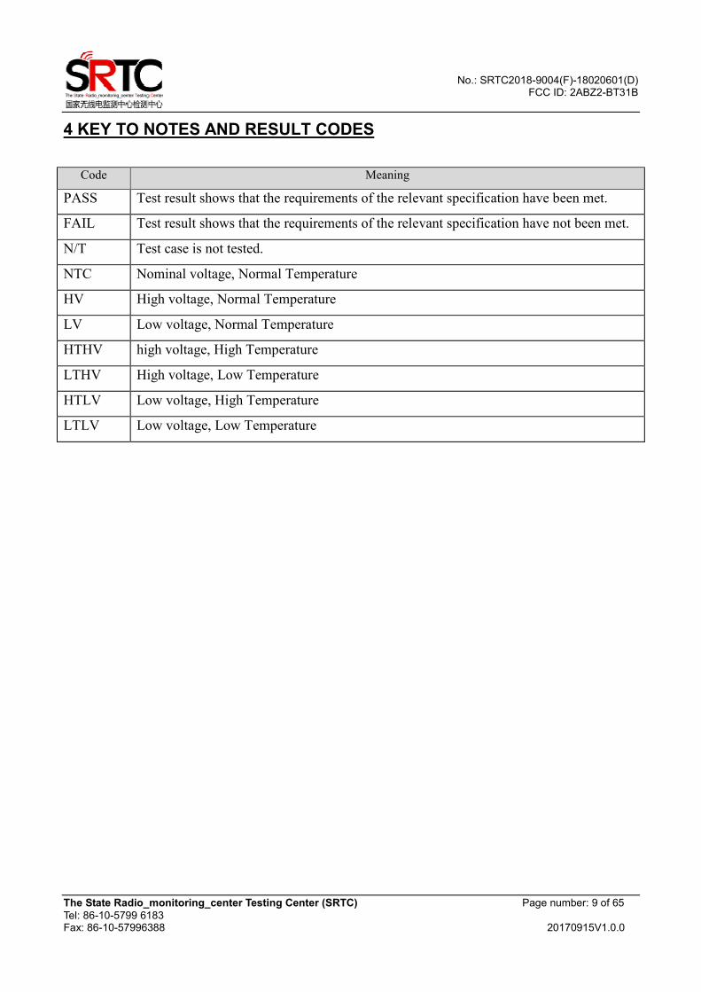
4 KEY TO NOTES AND RESULT CODES
Code Meaning
PASS Test result shows that the requirements of the relevant specification have been met.
FAIL Test result shows that the requirements of the relevant specification have not been met.
N/T Test case is not tested.
NTC Nominal voltage, Normal Temperature
HV High voltage, Normal Temperature
LV Low voltage, Normal Temperature
HTHV high voltage, High Temperature
LTHV High voltage, Low Temperature
HTLV Low voltage, High Temperature
LTLV Low voltage, Low Temperature
No.: SRTC2018-9004(F)-18020601(D) FCC ID: 2ABZ2-BT31B
The State Radio_monitoring_center Testing Center (SRTC) Page number: 10 of 65
Tel: 86-10-5799 6183 Fax: 86-10-57996388 20170915V1.0.0
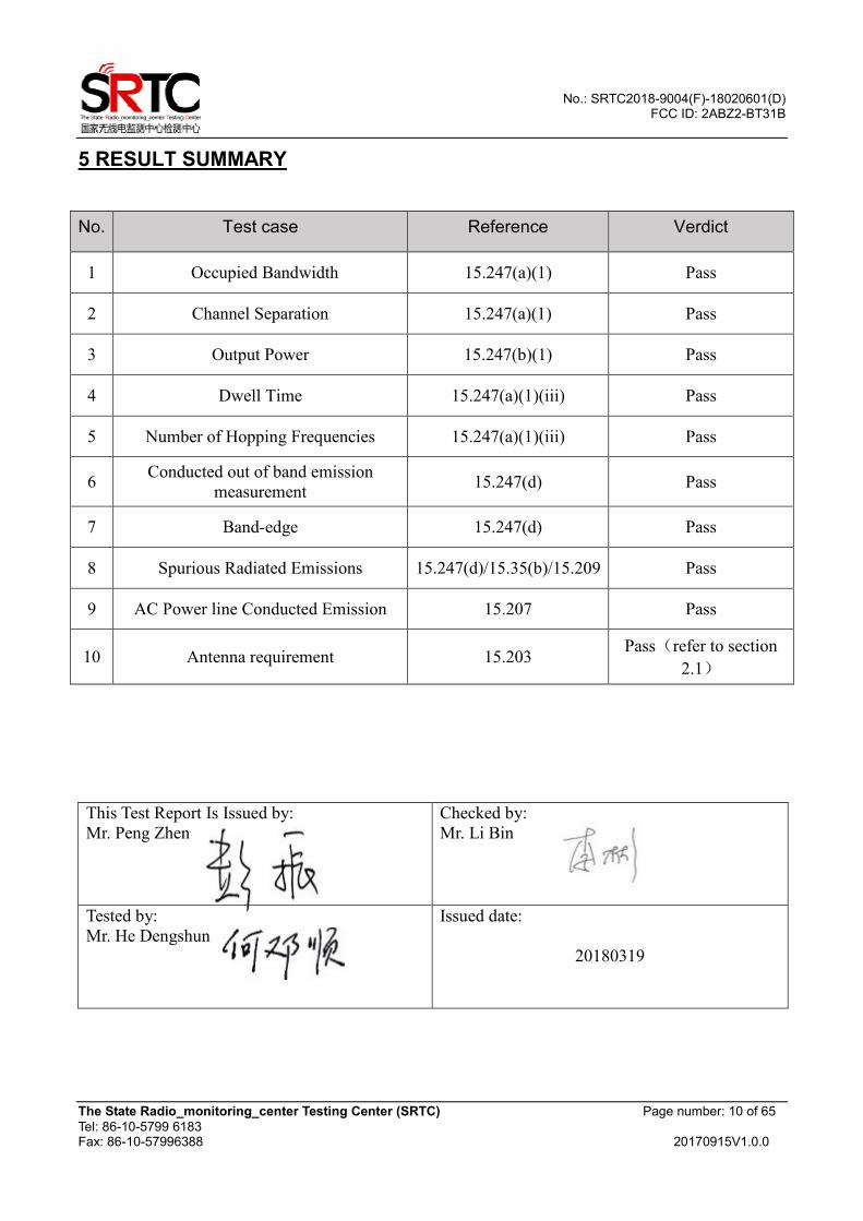
5 RESULT SUMMARY
No. Test case Reference Verdict
1 Occupied Bandwidth 15.247(a)(1) Pass
2 Channel Separation 15.247(a)(1) Pass
3 Output Power 15.247(b)(1) Pass
4 Dwell Time 15.247(a)(1)(iii) Pass
5 Number of Hopping Frequencies 15.247(a)(1)(iii) Pass
6 Conducted out of band emission
measurement 15.247(d) Pass
7 Band-edge 15.247(d) Pass
8 Spurious Radiated Emissions 15.247(d)/15.35(b)/15.209 Pass
9 AC Power line Conducted Emission 15.207 Pass
10 Antenna requirement 15.203 Pass(refer to section
2.1)
This Test Report Is Issued by:
Mr. Peng Zhen
Checked by:
Mr. Li Bin
Tested by:
Mr. He Dengshun
Issued date:
20180319
No.: SRTC2018-9004(F)-18020601(D) FCC ID: 2ABZ2-BT31B
The State Radio_monitoring_center Testing Center (SRTC) Page number: 11 of 65
Tel: 86-10-5799 6183 Fax: 86-10-57996388 20170915V1.0.0
6 TEST RESULT
6.1 Occupied Bandwidth
6.1.1 Ambient condition
Temperature Relative humidity Pressure
22°C 33% 101.5kPa
6.1.2 Test Description The bandwidth at 20dB down from the highest in-band spectral density is measured with a spectrum
analyzer and Bluetooth test set via a power splitter with a known loss which connected to the
transmitter antenna terminal of the EUT while the EUT is operating at maximum power and at the
appropriate frequencies. All modes of operation were investigated and the worst case configuration
results are reported in this section.
6.1.3 Test limit FCC Part15.247 (a)
For frequency hopping system operating in the 2400-2483.5MHz, If the 20dB bandwidth of hopping
channel is greater than 25kHz, two-thirds 20dB bandwidth of hopping channel shell be a minimum
limit for the hopping channel separation.
6.1.4 Test settings a. Check the calibration of the measuring instrument using either an internal calibrator or a known
signal from an external generator.
b. Turn on the EUT and connect it to measurement instrument. Then set it to any one convenient
frequency within its operating range. Set a reference level on the measuring instrument equal to the
highest peak value.
c. Measure the frequency difference of two frequencies that were attenuated 30dB from the reference
level. Record the frequency difference as the emission bandwidth.
d. Repeat above procedures until all frequencies measured were complete.
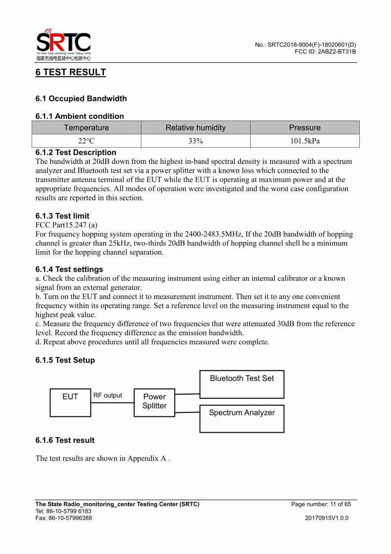
6.1.5 Test Setup
6.1.6 Test result The test results are shown in Appendix A .
Bluetooth Test Set
EUT RF output Power Splitter
Spectrum Analyzer
No.: SRTC2018-9004(F)-18020601(D) FCC ID: 2ABZ2-BT31B
The State Radio_monitoring_center Testing Center (SRTC) Page number: 12 of 65
Tel: 86-10-5799 6183 Fax: 86-10-57996388 20170915V1.0.0
6.2 Channel Separation
6.2.1 Ambient condition
Temperature Relative humidity Pressure
22°C 33% 101.5kPa
6.2.2 Test Description The Equipment Under Test (EUT) was set up in a shielded room to perform the channel separation
measurements. The EUT was connected to the spectrum analyzer and Bluetooth test set via a power
splitter with a known loss.
6.2.3 Test limit FCC Part15.247 (a)(1)
Measurement is made with EUT operating in hopping mode. The minimum permissible channel
separation for this system is 2/3 the value of the 20dB BW.
6.2.4 Test Settings ANSI C63.10-2013 Section 7.8.2
The EUT shall have its hopping function enabled. Use the following spectrum analyzer settings:
a) Span: Wide enough to capture the peaks of two adjacent channels.
b) RBW: Start with the RBW set to approximately 30% of the channel spacing; adjust as necessary
to best identify the center of each individual channel.
c) Video (or average) bandwidth (VBW) ≥ RBW.
d) Sweep: Auto.
e) Detector function: Peak.
f) Trace: Max hold.
g) Allow the trace to stabilize.
Use the marker-delta function to determine the separation between the peaks of the adjacent channels.
Compliance of an EUT with the appropriate regulatory limit shall be determined. A plot of the data
shall be included in the test report.
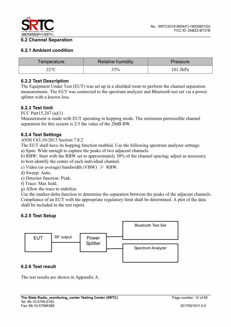
6.2.5 Test Setup
6.2.6 Test result The test results are shown in Appendix A .
Bluetooth Test Set
EUT RF output Power
Splitter Spectrum Analyzer
No.: SRTC2018-9004(F)-18020601(D) FCC ID: 2ABZ2-BT31B
The State Radio_monitoring_center Testing Center (SRTC) Page number: 13 of 65
Tel: 86-10-5799 6183 Fax: 86-10-57996388 20170915V1.0.0
6.3 Output Power
6.3.1 Ambient condition
Temperature Relative humidity Pressure
22°C 33% 101.5kPa
6.3.2 Test Description Measurement is made while the EUT is operating in non-hopping transmission mode. The powers
shown below were measured using a spectrum analyzer with a Bluetooth signalling test set used only
to maintain a Bluetooth link with the EUT.
6.3.3 Test limit FCC Part15.247(b)(1)
For frequency hopping systems operating in the 2400-2483.5 MHz band employing at least 75
non-overlapping hopping channels, and all frequency hopping systems in the 5725-5850 MHz band:
1 watt.
Used conversion factor: Limit (dBm) = 10 log (Limit (W)/1mW) �
Modulation type GFSK π/4DQPSK 8DPSK
Maximum Output Power 30.0dBm 30.0dBm 30.0dBm
For all other frequency hopping systems in the 2400-2483.5 MHz band: 0.125 watts.
Used conversion factor: Limit (dBm) = 10 log (Limit (W)/1mW) �
Modulation type GFSK π/4DQPSK 8DPSK
Maximum Output Power 21.0dBm 21.0dBm 21.0dBm
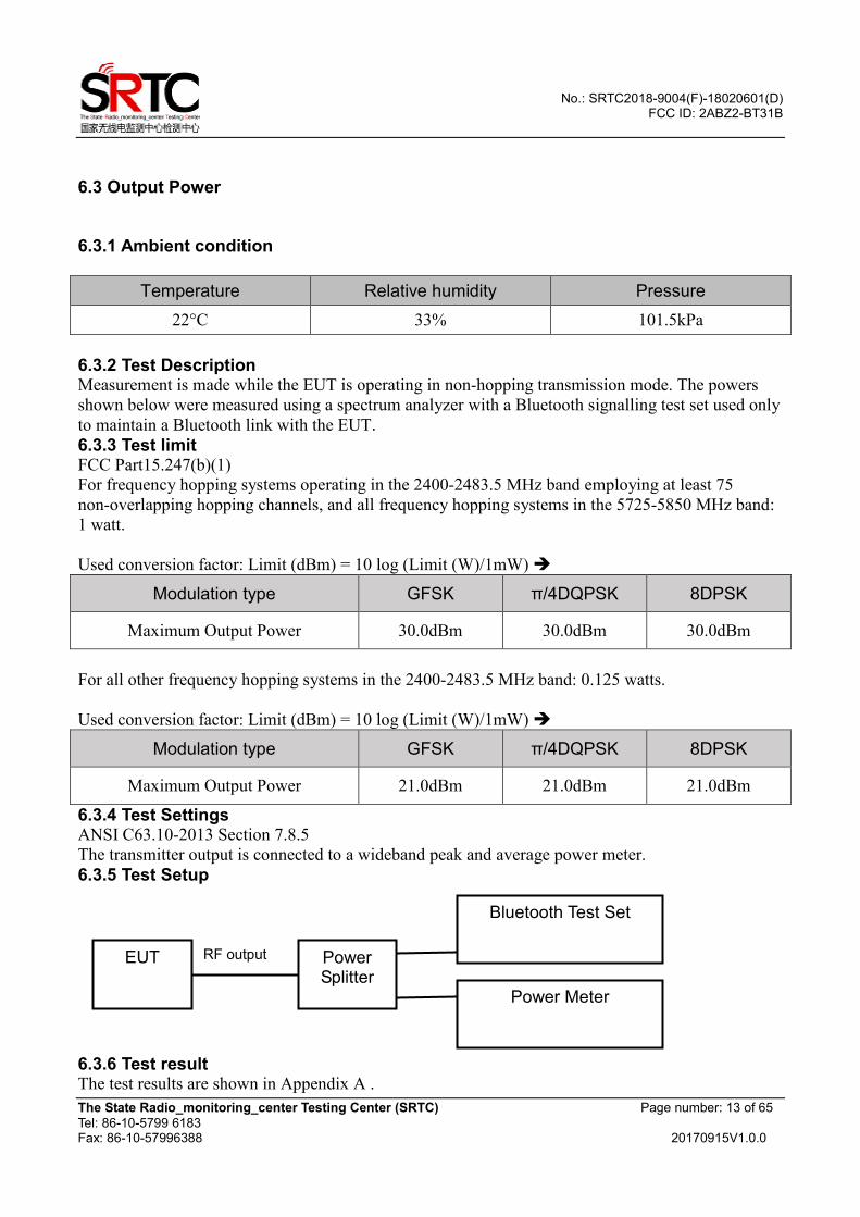
6.3.4 Test Settings ANSI C63.10-2013 Section 7.8.5
The transmitter output is connected to a wideband peak and average power meter.
6.3.5 Test Setup
6.3.6 Test result The test results are shown in Appendix A .
Bluetooth Test Set
EUT RF output Power Splitter
Power Meter
No.: SRTC2018-9004(F)-18020601(D) FCC ID: 2ABZ2-BT31B
The State Radio_monitoring_center Testing Center (SRTC) Page number: 14 of 65
Tel: 86-10-5799 6183 Fax: 86-10-57996388 20170915V1.0.0
6.4 Dwell Time
6.4.1 Ambient condition
Temperature Relative humidity Pressure
22°C 33% 101.5kPa
6.4.2 Test Description
The Equipment Under Test (EUT) was set up in a shielded room to perform the dwell time
measurements.
The EUT was connected to the spectrum analyzer and Bluetooth test set via a power splitter with a
known loss.
The time slot length is measured of three different packet types which are available in the Bluetooth
technology. Those are DH1, DH3 and DH5 packets. The dwell time is calculated by:
Dwell time = time slot length * hop rate * 31.6/ number of hopping channels with:
- hop rate=1600/2 * 1/s for DH1 packets =800
- hop rate=1600/4 * 1/s for DH3 packets =400
- hop rate=1600/6 * 1/s for DH5 packets =266.67
- number of hopping channels=79
- 31.6 s=0.4 seconds multiplied by the number of hopping channels=0.4s * 79
6.4.3 Test limit FCC Part15.247(a)(1)(iii)
Frequency hopping systems in the 2400-2483.5 MHz band shall use at least 15 channels. The
average time of occupancy on any channel shall not be greater than 0.4 seconds within a period of
0.4 seconds multiplied by the number of hopping channels employed.
6.4.4 Test Settings ANSI C63.10-2013 Section 7.8.4 The EUT shall have its hopping function enabled. Use the following spectrum analyzer settings:
a) Span: Zero span, centered on a hopping channel.
b) RBW shall be ≤ channel spacing and where possible RBW should be set >> 1 / T, where T is
the expected dwell time per channel.
c) Sweep: As necessary to capture the entire dwell time per hopping channel; where possible use a
video trigger and trigger delay so that the transmitted signal starts a little to the right of the start of
the plot. The trigger level might need slight adjustment to prevent triggering when the system hops
on an adjacent channel; a second plot might be needed with a longer sweep time to show two
successive hops on a channel.
d) Detector function: Peak.
e) Trace: Max hold.
Use the marker-delta function to determine the transmit time per hop. If this value varies with
different modes of operation (data rate, modulation format, number of hopping channels, etc.), then
repeat this test for each variation in transmit time.
No.: SRTC2018-9004(F)-18020601(D) FCC ID: 2ABZ2-BT31B
The State Radio_monitoring_center Testing Center (SRTC) Page number: 15 of 65
Tel: 86-10-5799 6183 Fax: 86-10-57996388 20170915V1.0.0
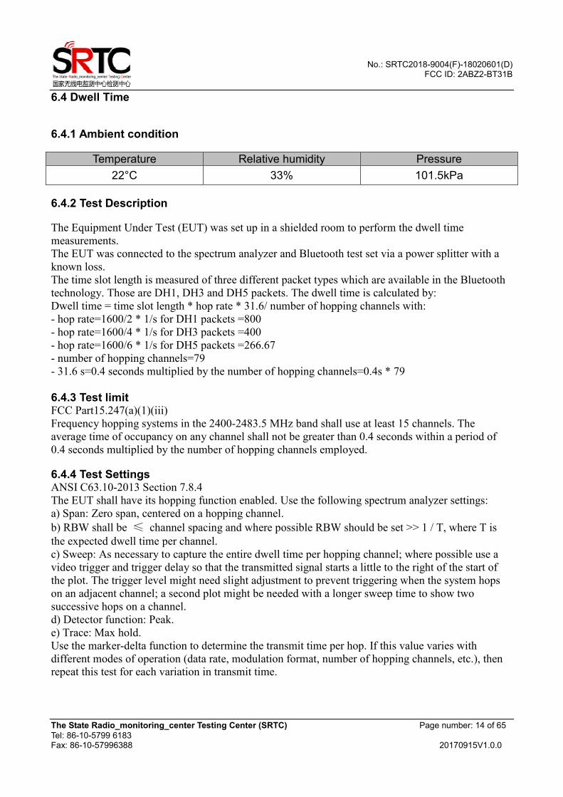
6.4.5 Test Setup
6.4.6 Test result The test results are shown in Appendix A .
Bluetooth Test Set
EUT RF output Power
Splitter Spectrum Analyzer
No.: SRTC2018-9004(F)-18020601(D) FCC ID: 2ABZ2-BT31B
The State Radio_monitoring_center Testing Center (SRTC) Page number: 16 of 65
Tel: 86-10-5799 6183 Fax: 86-10-57996388 20170915V1.0.0
6.5 Number of Hopping Frequencies
6.5.1 Ambient condition
Temperature Relative humidity Pressure 22°C 33% 101.5kPa
6.5.2 Test Description The Equipment Under Test (EUT) was set up in a shielded room to perform the number of hopping
frequencies measurement. The EUT was connected to the spectrum analyzer and Bluetooth test set
via a power splitter with a known loss.
6.5.3 Test limit FCC Part15.247(a)(1)(iii)
Frequency hopping systems in the 2400-2483.5 MHz band shall use at least 15 channels.
6.5.4 Test Settings ANSI C63.10-2013 Section 7.8.3
The EUT shall have its hopping function enabled. Use the following spectrum analyzer settings:
a) Span: The frequency band of operation. Depending on the number of channels the device supports,
it may be necessary to divide the frequency range of operation across multiple spans, to allow the
individual channels to be clearly seen.
b) RBW: To identify clearly the individual channels, set the RBW to less than 30% of the channel
spacing or the 20 dB bandwidth, whichever is smaller.
c) VBW ≥ RBW.
d) Sweep: Auto.
e) Detector function: Peak.
f) Trace: Max hold.
g) Allow the trace to stabilize.
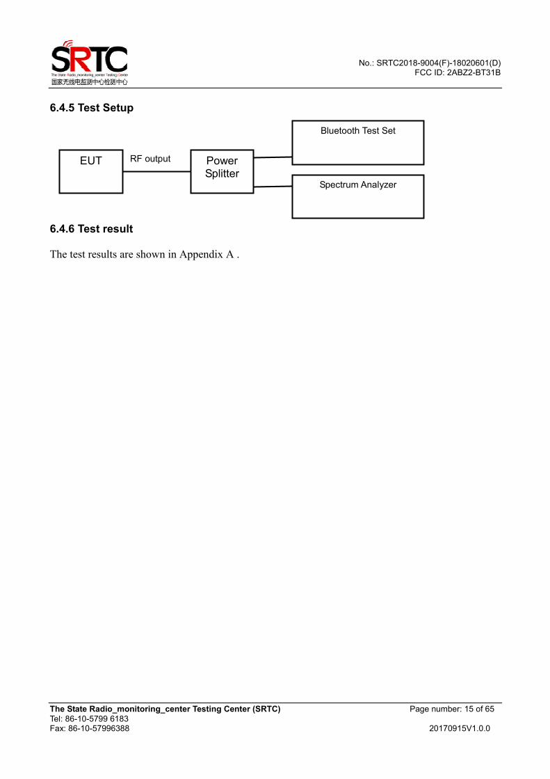
6.5.5 Test Setup
6.5.6 Test result The test results are shown in Appendix A.
Bluetooth Test Set
EUT RF output Power
Splitter Spectrum Analyzer
No.: SRTC2018-9004(F)-18020601(D) FCC ID: 2ABZ2-BT31B
The State Radio_monitoring_center Testing Center (SRTC) Page number: 17 of 65
Tel: 86-10-5799 6183 Fax: 86-10-57996388 20170915V1.0.0
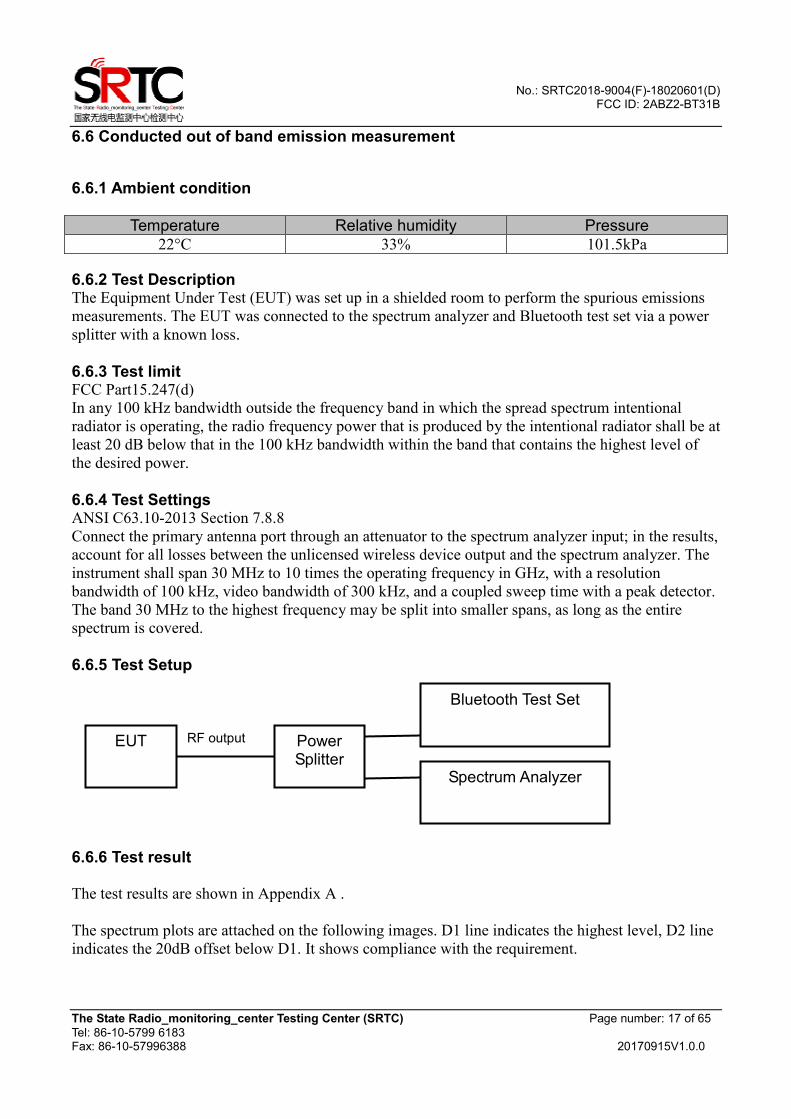
6.6 Conducted out of band emission measurement
6.6.1 Ambient condition
Temperature Relative humidity Pressure 22°C 33% 101.5kPa
6.6.2 Test Description The Equipment Under Test (EUT) was set up in a shielded room to perform the spurious emissions
measurements. The EUT was connected to the spectrum analyzer and Bluetooth test set via a power
splitter with a known loss.
6.6.3 Test limit FCC Part15.247(d)
In any 100 kHz bandwidth outside the frequency band in which the spread spectrum intentional
radiator is operating, the radio frequency power that is produced by the intentional radiator shall be at
least 20 dB below that in the 100 kHz bandwidth within the band that contains the highest level of
the desired power.
6.6.4 Test Settings ANSI C63.10-2013 Section 7.8.8
Connect the primary antenna port through an attenuator to the spectrum analyzer input; in the results,
account for all losses between the unlicensed wireless device output and the spectrum analyzer. The
instrument shall span 30 MHz to 10 times the operating frequency in GHz, with a resolution
bandwidth of 100 kHz, video bandwidth of 300 kHz, and a coupled sweep time with a peak detector.
The band 30 MHz to the highest frequency may be split into smaller spans, as long as the entire
spectrum is covered.
6.6.5 Test Setup
6.6.6 Test result The test results are shown in Appendix A .
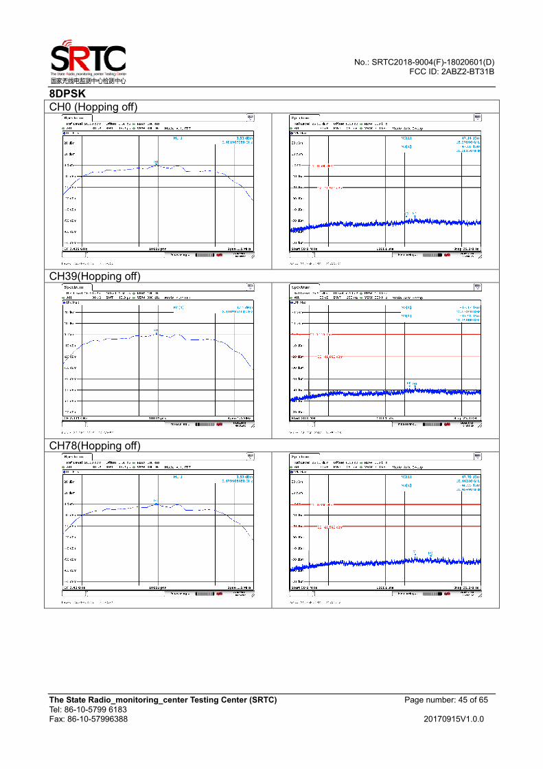
The spectrum plots are attached on the following images. D1 line indicates the highest level, D2 line
indicates the 20dB offset below D1. It shows compliance with the requirement.
Bluetooth Test Set
EUT RF output Power Splitter
Spectrum Analyzer
No.: SRTC2018-9004(F)-18020601(D) FCC ID: 2ABZ2-BT31B
The State Radio_monitoring_center Testing Center (SRTC) Page number: 18 of 65
Tel: 86-10-5799 6183 Fax: 86-10-57996388 20170915V1.0.0
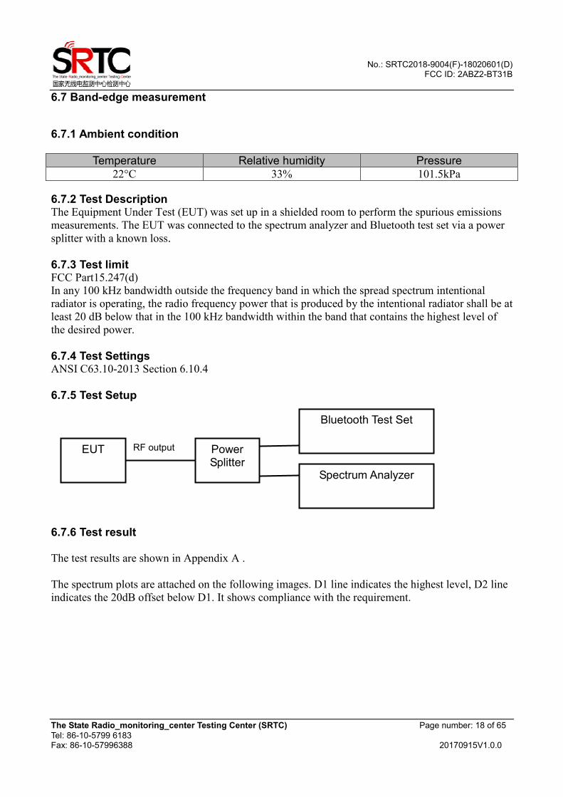
6.7 Band-edge measurement
6.7.1 Ambient condition
Temperature Relative humidity Pressure 22°C 33% 101.5kPa
6.7.2 Test Description The Equipment Under Test (EUT) was set up in a shielded room to perform the spurious emissions
measurements. The EUT was connected to the spectrum analyzer and Bluetooth test set via a power
splitter with a known loss.
6.7.3 Test limit FCC Part15.247(d)
In any 100 kHz bandwidth outside the frequency band in which the spread spectrum intentional
radiator is operating, the radio frequency power that is produced by the intentional radiator shall be at
least 20 dB below that in the 100 kHz bandwidth within the band that contains the highest level of
the desired power.
6.7.4 Test Settings ANSI C63.10-2013 Section 6.10.4
6.7.5 Test Setup
6.7.6 Test result The test results are shown in Appendix A .
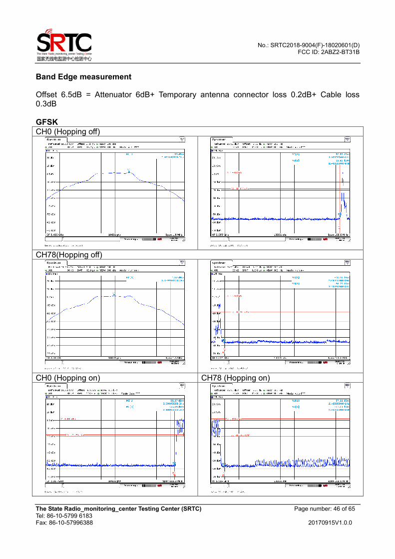
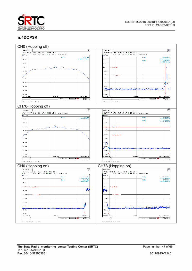
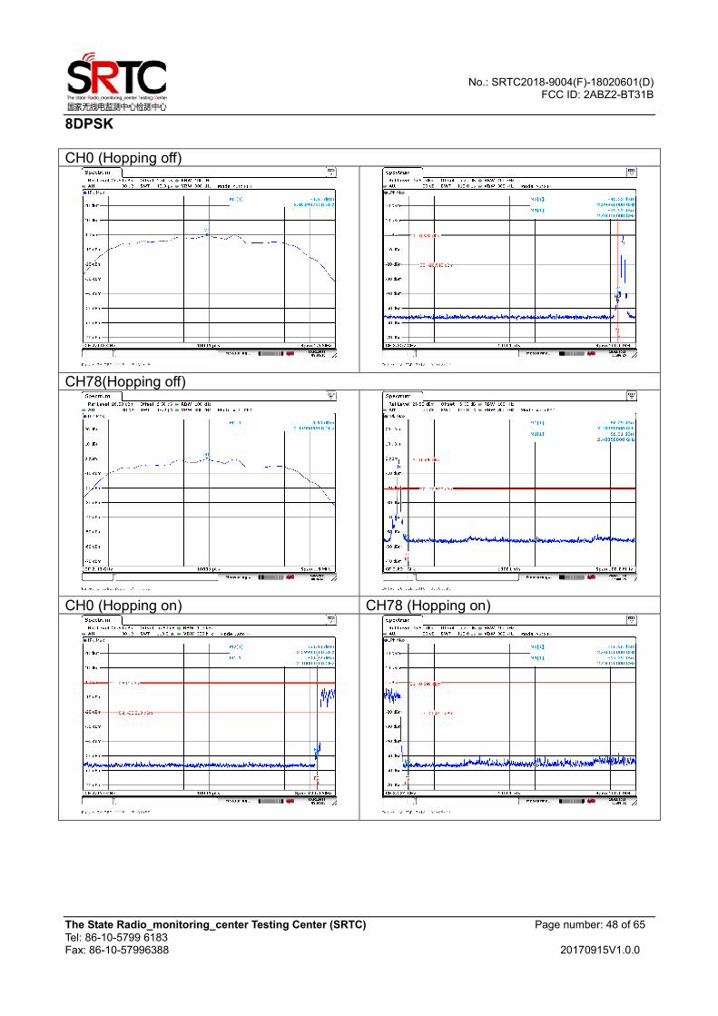
The spectrum plots are attached on the following images. D1 line indicates the highest level, D2 line
indicates the 20dB offset below D1. It shows compliance with the requirement.
Bluetooth Test Set
EUT RF output Power Splitter
Spectrum Analyzer
No.: SRTC2018-9004(F)-18020601(D) FCC ID: 2ABZ2-BT31B
The State Radio_monitoring_center Testing Center (SRTC) Page number: 19 of 65
Tel: 86-10-5799 6183 Fax: 86-10-57996388 20170915V1.0.0
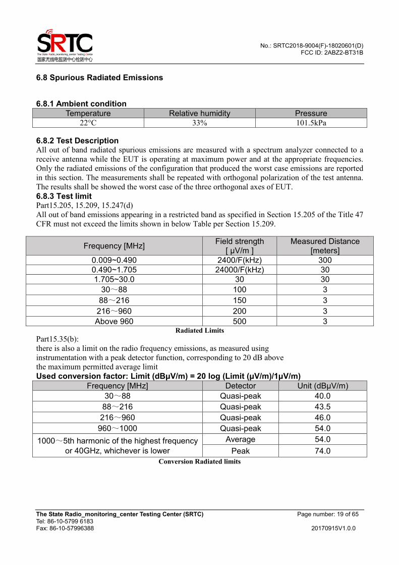
6.8 Spurious Radiated Emissions
6.8.1 Ambient condition
Temperature Relative humidity Pressure 22°C 33% 101.5kPa
6.8.2 Test Description All out of band radiated spurious emissions are measured with a spectrum analyzer connected to a
receive antenna while the EUT is operating at maximum power and at the appropriate frequencies.
Only the radiated emissions of the configuration that produced the worst case emissions are reported
in this section. The measurements shall be repeated with orthogonal polarization of the test antenna.
The results shall be showed the worst case of the three orthogonal axes of EUT.
6.8.3 Test limit Part15.205, 15.209, 15.247(d)
All out of band emissions appearing in a restricted band as specified in Section 15.205 of the Title 47
CFR must not exceed the limits shown in below Table per Section 15.209.
Frequency [MHz] Field strength
[ µV/m ] Measured Distance
[meters]
0.009~0.490 2400/F(kHz) 300
0.490~1.705 24000/F(kHz) 30
1.705~30.0 30 30
30~88 100 3
88~216 150 3
216~960 200 3
Above 960 500 3 Radiated Limits
Part15.35(b):
there is also a limit on the radio frequency emissions, as measured using
instrumentation with a peak detector function, corresponding to 20 dB above
the maximum permitted average limit
Used conversion factor: Limit (dBµV/m) = 20 log (Limit (µV/m)/1µV/m)
Frequency [MHz] Detector Unit (dBµV/m)
30~88 Quasi-peak 40.0
88~216 Quasi-peak 43.5
216~960 Quasi-peak 46.0
960~1000 Quasi-peak 54.0
1000~5th harmonic of the highest frequency
or 40GHz, whichever is lower
Average 54.0
Peak 74.0
Conversion Radiated limits
No.: SRTC2018-9004(F)-18020601(D) FCC ID: 2ABZ2-BT31B
The State Radio_monitoring_center Testing Center (SRTC) Page number: 20 of 65
Tel: 86-10-5799 6183 Fax: 86-10-57996388 20170915V1.0.0
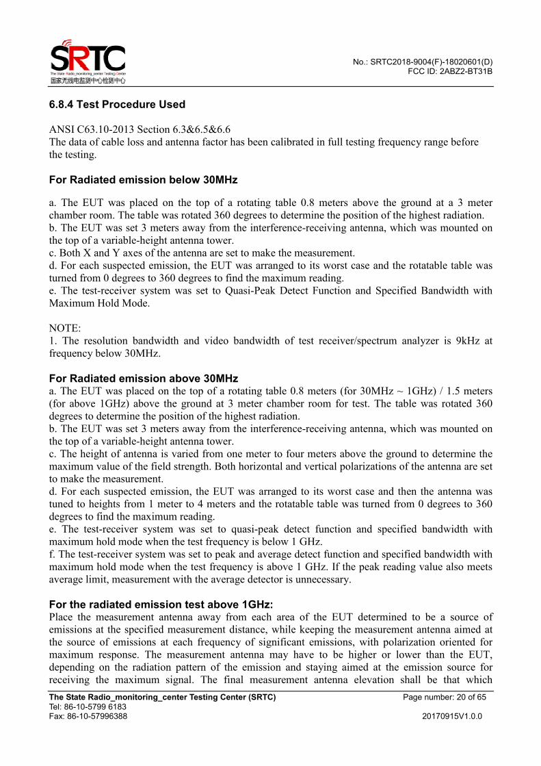
6.8.4 Test Procedure Used ANSI C63.10-2013 Section 6.3&6.5&6.6
The data of cable loss and antenna factor has been calibrated in full testing frequency range before
the testing.
For Radiated emission below 30MHz
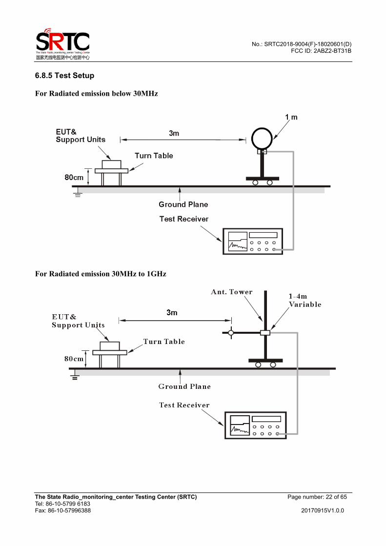
a. The EUT was placed on the top of a rotating table 0.8 meters above the ground at a 3 meter
chamber room. The table was rotated 360 degrees to determine the position of the highest radiation.
b. The EUT was set 3 meters away from the interference-receiving antenna, which was mounted on
the top of a variable-height antenna tower.
c. Both X and Y axes of the antenna are set to make the measurement.
d. For each suspected emission, the EUT was arranged to its worst case and the rotatable table was
turned from 0 degrees to 360 degrees to find the maximum reading.
e. The test-receiver system was set to Quasi-Peak Detect Function and Specified Bandwidth with
Maximum Hold Mode.
NOTE:
1. The resolution bandwidth and video bandwidth of test receiver/spectrum analyzer is 9kHz at
frequency below 30MHz.
For Radiated emission above 30MHz a. The EUT was placed on the top of a rotating table 0.8 meters (for 30MHz ~ 1GHz) / 1.5 meters
(for above 1GHz) above the ground at 3 meter chamber room for test. The table was rotated 360
degrees to determine the position of the highest radiation.
b. The EUT was set 3 meters away from the interference-receiving antenna, which was mounted on
the top of a variable-height antenna tower.
c. The height of antenna is varied from one meter to four meters above the ground to determine the
maximum value of the field strength. Both horizontal and vertical polarizations of the antenna are set
to make the measurement.
d. For each suspected emission, the EUT was arranged to its worst case and then the antenna was
tuned to heights from 1 meter to 4 meters and the rotatable table was turned from 0 degrees to 360
degrees to find the maximum reading.
e. The test-receiver system was set to quasi-peak detect function and specified bandwidth with
maximum hold mode when the test frequency is below 1 GHz.
f. The test-receiver system was set to peak and average detect function and specified bandwidth with
maximum hold mode when the test frequency is above 1 GHz. If the peak reading value also meets
average limit, measurement with the average detector is unnecessary.
For the radiated emission test above 1GHz: Place the measurement antenna away from each area of the EUT determined to be a source of
emissions at the specified measurement distance, while keeping the measurement antenna aimed at
the source of emissions at each frequency of significant emissions, with polarization oriented for
maximum response. The measurement antenna may have to be higher or lower than the EUT,
depending on the radiation pattern of the emission and staying aimed at the emission source for
receiving the maximum signal. The final measurement antenna elevation shall be that which
No.: SRTC2018-9004(F)-18020601(D) FCC ID: 2ABZ2-BT31B
The State Radio_monitoring_center Testing Center (SRTC) Page number: 21 of 65
Tel: 86-10-5799 6183 Fax: 86-10-57996388 20170915V1.0.0
maximizes the emissions. The measurement antenna elevation for maximum emissions shall be
restricted to a range of heights of from 1 m to 4 m above the ground or reference ground plane.
NOTE:
1. The resolution bandwidth and video bandwidth of test receiver/spectrum analyzer is 120kHz for
Quasi-peak detection (QP) at frequency below 1GHz.
2. The resolution bandwidth of test receiver/spectrum analyzer is 1 MHz and the video bandwidth is
3 MHz for Peak detection (PK) at frequency above 1GHz.
3. The resolution bandwidth of test receiver/spectrum analyzer is 1 MHz and the video bandwidth is
3 MHz for Average detection (AV) at frequency above 1GHz. If duty cycle of test signal is < 98%,
the duty factor need added to measured value.
4. All modes of operation were investigated and the worst-case emissions are reported.
No.: SRTC2018-9004(F)-18020601(D) FCC ID: 2ABZ2-BT31B
The State Radio_monitoring_center Testing Center (SRTC) Page number: 22 of 65
Tel: 86-10-5799 6183 Fax: 86-10-57996388 20170915V1.0.0
6.8.5 Test Setup
For Radiated emission below 30MHz
For Radiated emission 30MHz to 1GHz

No.: SRTC2018-9004(F)-18020601(D) FCC ID: 2ABZ2-BT31B
The State Radio_monitoring_center Testing Center (SRTC) Page number: 23 of 65
Tel: 86-10-5799 6183 Fax: 86-10-57996388 20170915V1.0.0
For Radiated emission above 1GHz
6.8.6 Test result
The test results are shown in Appendix B.
No.: SRTC2018-9004(F)-18020601(D) FCC ID: 2ABZ2-BT31B
The State Radio_monitoring_center Testing Center (SRTC) Page number: 24 of 65
Tel: 86-10-5799 6183 Fax: 86-10-57996388 20170915V1.0.0
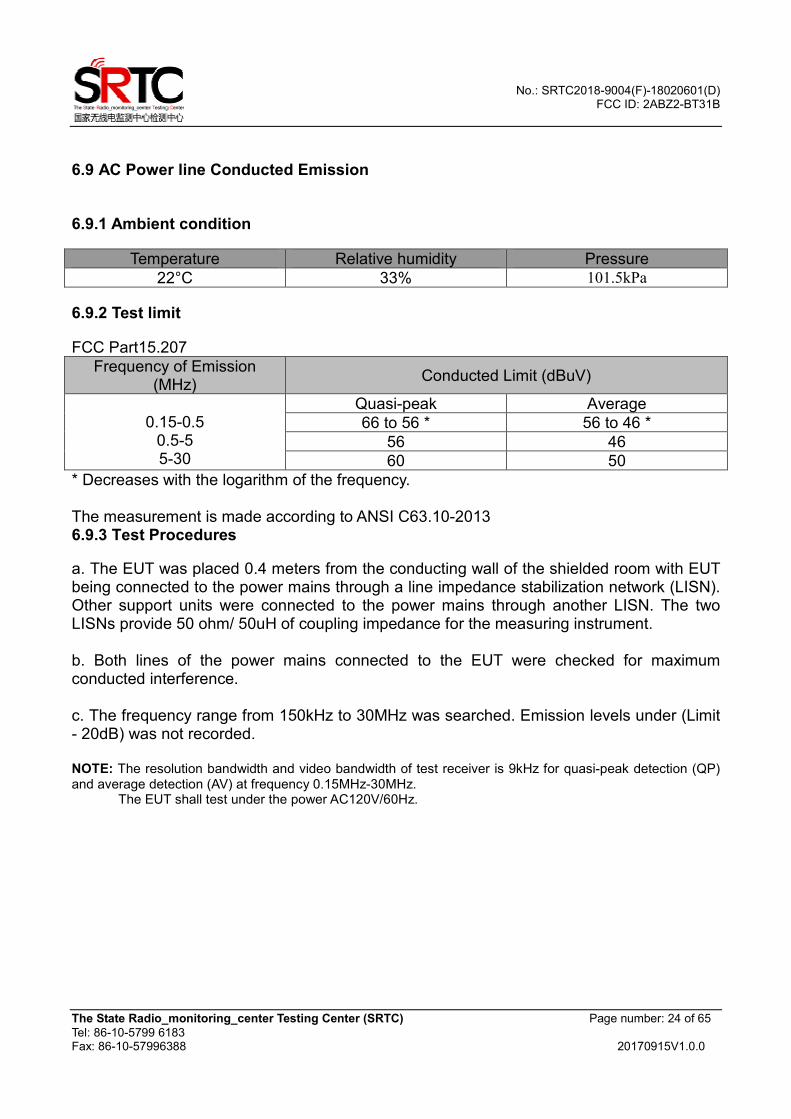
6.9 AC Power line Conducted Emission
6.9.1 Ambient condition
Temperature Relative humidity Pressure
22°C 33% 101.5kPa
6.9.2 Test limit
FCC Part15.207
Frequency of Emission (MHz)
Conducted Limit (dBuV)
0.15-0.5
0.5-5 5-30
Quasi-peak Average
66 to 56 * 56 to 46 *
56 46
60 50
* Decreases with the logarithm of the frequency. The measurement is made according to ANSI C63.10-2013 6.9.3 Test Procedures
a. The EUT was placed 0.4 meters from the conducting wall of the shielded room with EUT being connected to the power mains through a line impedance stabilization network (LISN). Other support units were connected to the power mains through another LISN. The two LISNs provide 50 ohm/ 50uH of coupling impedance for the measuring instrument. b. Both lines of the power mains connected to the EUT were checked for maximum conducted interference. c. The frequency range from 150kHz to 30MHz was searched. Emission levels under (Limit - 20dB) was not recorded. NOTE: The resolution bandwidth and video bandwidth of test receiver is 9kHz for quasi-peak detection (QP) and average detection (AV) at frequency 0.15MHz-30MHz. The EUT shall test under the power AC120V/60Hz.
No.: SRTC2018-9004(F)-18020601(D) FCC ID: 2ABZ2-BT31B
The State Radio_monitoring_center Testing Center (SRTC) Page number: 25 of 65
Tel: 86-10-5799 6183 Fax: 86-10-57996388 20170915V1.0.0
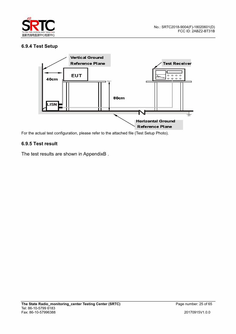
6.9.4 Test Setup
For the actual test configuration, please refer to the attached file (Test Setup Photo). 6.9.5 Test result
The test results are shown in AppendixB .
No.: SRTC2018-9004(F)-18020601(D) FCC ID: 2ABZ2-BT31B
The State Radio_monitoring_center Testing Center (SRTC) Page number: 26 of 65
Tel: 86-10-5799 6183 Fax: 86-10-57996388 20170915V1.0.0
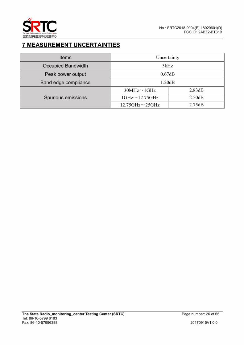
7 MEASUREMENT UNCERTAINTIES
Items Uncertainty
Occupied Bandwidth 3kHz
Peak power output 0.67dB
Band edge compliance 1.20dB
Spurious emissions
30MHz~1GHz 2.83dB
1GHz~12.75GHz 2.50dB
12.75GHz~25GHz 2.75dB
No.: SRTC2018-9004(F)-18020601(D) FCC ID: 2ABZ2-BT31B
The State Radio_monitoring_center Testing Center (SRTC) Page number: 27 of 65
Tel: 86-10-5799 6183 Fax: 86-10-57996388 20170915V1.0.0
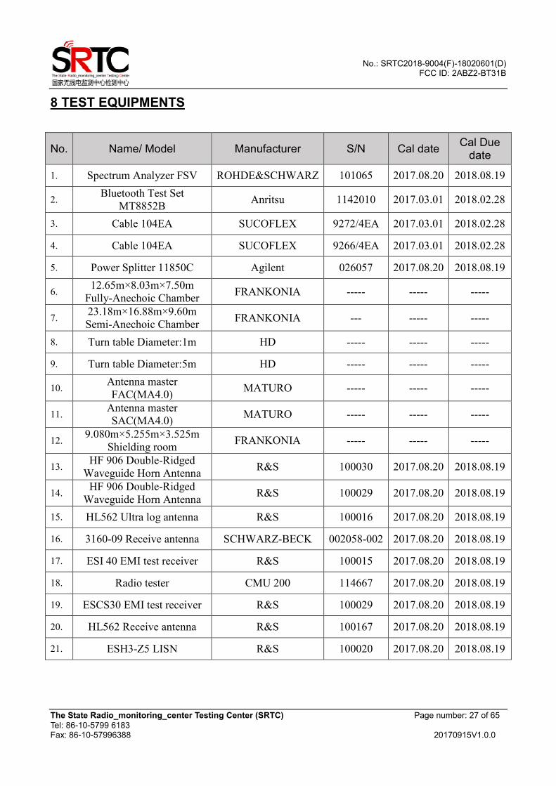
8 TEST EQUIPMENTS
No. Name/ Model Manufacturer S/N Cal date Cal Due
date
1. Spectrum Analyzer FSV ROHDE&SCHWARZ 101065 2017.08.20 2018.08.19
2. Bluetooth Test Set
MT8852B Anritsu 1142010 2017.03.01 2018.02.28
3. Cable 104EA SUCOFLEX 9272/4EA 2017.03.01 2018.02.28
4. Cable 104EA SUCOFLEX 9266/4EA 2017.03.01 2018.02.28
5. Power Splitter 11850C Agilent 026057 2017.08.20 2018.08.19
6. 12.65m×8.03m×7.50m
Fully-Anechoic Chamber FRANKONIA ----- ----- -----
7. 23.18m×16.88m×9.60m
Semi-Anechoic Chamber FRANKONIA --- ----- -----
8. Turn table Diameter:1m HD ----- ----- -----
9. Turn table Diameter:5m HD ----- ----- -----
10. Antenna master
FAC(MA4.0) MATURO ----- ----- -----
11. Antenna master
SAC(MA4.0) MATURO ----- ----- -----
12. 9.080m×5.255m×3.525m
Shielding room FRANKONIA ----- ----- -----
13. HF 906 Double-Ridged
Waveguide Horn Antenna R&S 100030 2017.08.20 2018.08.19
14. HF 906 Double-Ridged
Waveguide Horn Antenna R&S 100029 2017.08.20 2018.08.19
15. HL562 Ultra log antenna R&S 100016 2017.08.20 2018.08.19
16. 3160-09 Receive antenna SCHWARZ-BECK 002058-002 2017.08.20 2018.08.19
17. ESI 40 EMI test receiver R&S 100015 2017.08.20 2018.08.19
18. Radio tester CMU 200 114667 2017.08.20 2018.08.19
19. ESCS30 EMI test receiver R&S 100029 2017.08.20 2018.08.19
20. HL562 Receive antenna R&S 100167 2017.08.20 2018.08.19
21. ESH3-Z5 LISN R&S 100020 2017.08.20 2018.08.19
No.: SRTC2018-9004(F)-18020601(D) FCC ID: 2ABZ2-BT31B
The State Radio_monitoring_center Testing Center (SRTC) Page number: 28 of 65
Tel: 86-10-5799 6183 Fax: 86-10-57996388 20170915V1.0.0
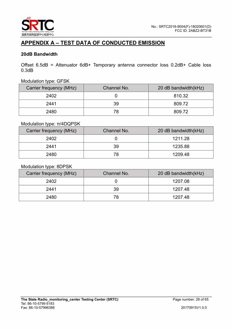
APPENDIX A – TEST DATA OF CONDUCTED EMISSION 20dB Bandwidth Offset 6.5dB = Attenuator 6dB+ Temporary antenna connector loss 0.2dB+ Cable loss 0.3dB Modulation type: GFSK
Carrier frequency (MHz) Channel No. 20 dB bandwidth(kHz)
2402 0 810.32
2441 39 809.72
2480 78 809.72
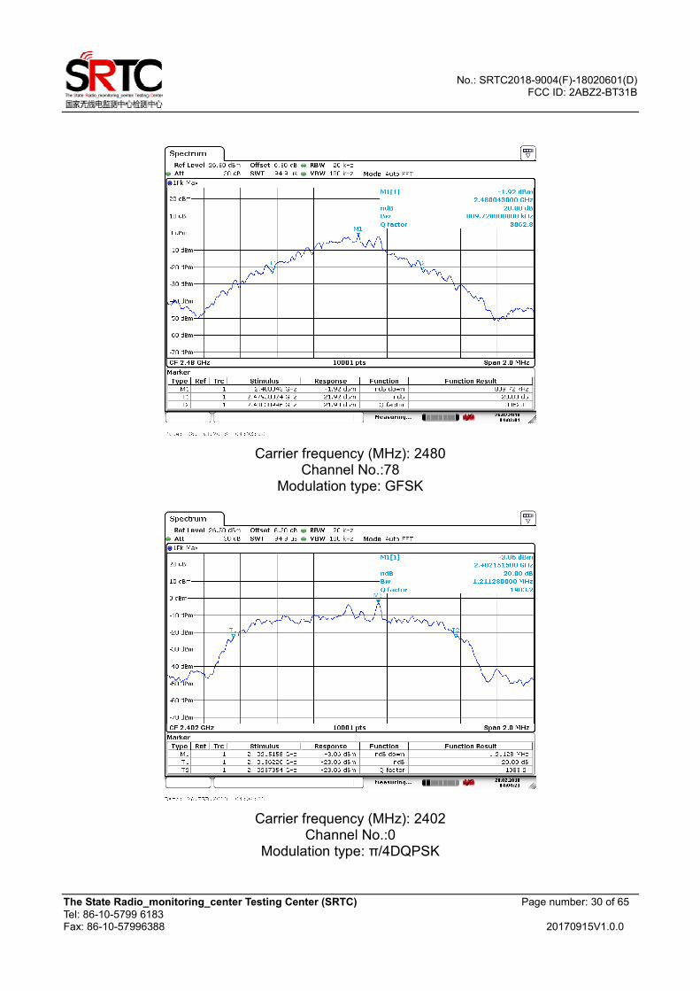
Modulation type: π/4DQPSK
Carrier frequency (MHz) Channel No. 20 dB bandwidth(kHz)
2402 0 1211.28
2441 39 1235.88
2480 78 1209.48
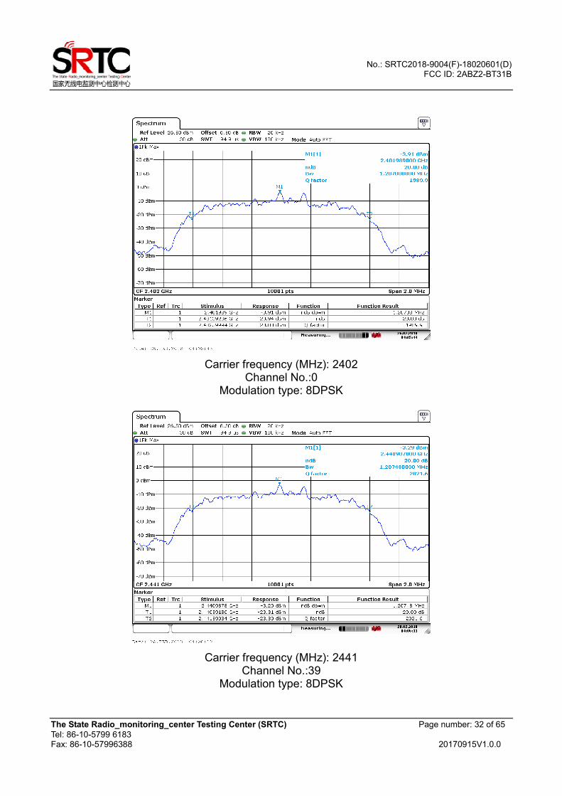
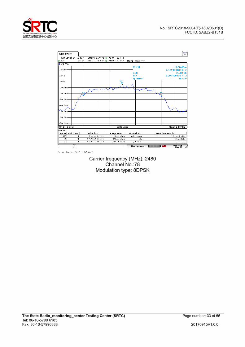
Modulation type: 8DPSK
Carrier frequency (MHz) Channel No. 20 dB bandwidth(kHz)
2402 0 1207.08
2441 39 1207.48
2480 78 1207.48
No.: SRTC2018-9004(F)-18020601(D) FCC ID: 2ABZ2-BT31B
The State Radio_monitoring_center Testing Center (SRTC) Page number: 29 of 65
Tel: 86-10-5799 6183 Fax: 86-10-57996388 20170915V1.0.0
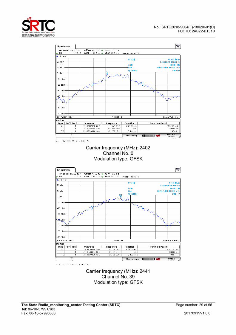
Carrier frequency (MHz): 2402
Channel No.:0 Modulation type: GFSK
Carrier frequency (MHz): 2441
Channel No.:39 Modulation type: GFSK
No.: SRTC2018-9004(F)-18020601(D) FCC ID: 2ABZ2-BT31B
The State Radio_monitoring_center Testing Center (SRTC) Page number: 30 of 65
Tel: 86-10-5799 6183 Fax: 86-10-57996388 20170915V1.0.0
Carrier frequency (MHz): 2480
Channel No.:78 Modulation type: GFSK
Carrier frequency (MHz): 2402
Channel No.:0 Modulation type: π/4DQPSK

No.: SRTC2018-9004(F)-18020601(D) FCC ID: 2ABZ2-BT31B
The State Radio_monitoring_center Testing Center (SRTC) Page number: 31 of 65
Tel: 86-10-5799 6183 Fax: 86-10-57996388 20170915V1.0.0
Carrier frequency (MHz): 2441
Channel No.:39 Modulation type: π/4DQPSK
Carrier frequency (MHz): 2480
Channel No.:78 Modulation type: π/4DQPSK
No.: SRTC2018-9004(F)-18020601(D) FCC ID: 2ABZ2-BT31B
The State Radio_monitoring_center Testing Center (SRTC) Page number: 32 of 65
Tel: 86-10-5799 6183 Fax: 86-10-57996388 20170915V1.0.0
Carrier frequency (MHz): 2402
Channel No.:0 Modulation type: 8DPSK
Carrier frequency (MHz): 2441
Channel No.:39 Modulation type: 8DPSK
No.: SRTC2018-9004(F)-18020601(D) FCC ID: 2ABZ2-BT31B
The State Radio_monitoring_center Testing Center (SRTC) Page number: 33 of 65
Tel: 86-10-5799 6183 Fax: 86-10-57996388 20170915V1.0.0
Carrier frequency (MHz): 2480
Channel No.:78 Modulation type: 8DPSK
No.: SRTC2018-9004(F)-18020601(D) FCC ID: 2ABZ2-BT31B
The State Radio_monitoring_center Testing Center (SRTC) Page number: 34 of 65
Tel: 86-10-5799 6183 Fax: 86-10-57996388 20170915V1.0.0
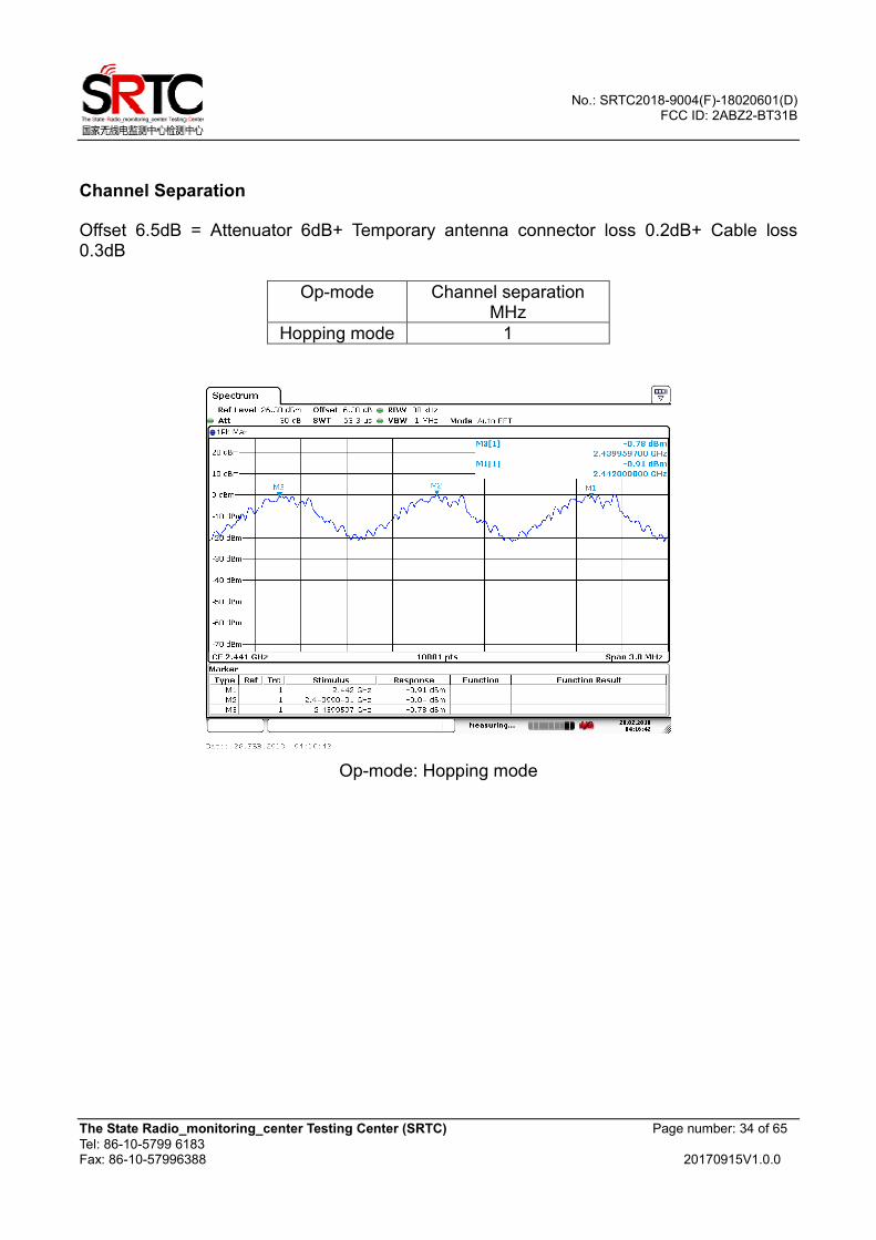
Channel Separation
Offset 6.5dB = Attenuator 6dB+ Temporary antenna connector loss 0.2dB+ Cable loss 0.3dB
Op-mode Channel separation MHz
Hopping mode 1
Op-mode: Hopping mode
No.: SRTC2018-9004(F)-18020601(D) FCC ID: 2ABZ2-BT31B
The State Radio_monitoring_center Testing Center (SRTC) Page number: 35 of 65
Tel: 86-10-5799 6183 Fax: 86-10-57996388 20170915V1.0.0
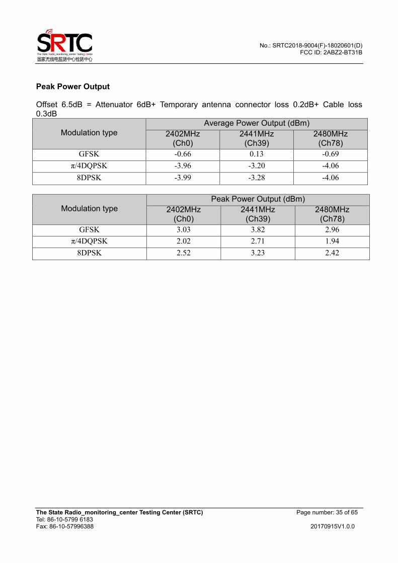
Peak Power Output
Offset 6.5dB = Attenuator 6dB+ Temporary antenna connector loss 0.2dB+ Cable loss 0.3dB
Modulation type
Average Power Output (dBm)
2402MHz (Ch0)
2441MHz (Ch39)
2480MHz (Ch78)
GFSK -0.66 0.13 -0.69
π/4DQPSK -3.96 -3.20 -4.06
8DPSK -3.99 -3.28 -4.06
Modulation type
Peak Power Output (dBm)
2402MHz (Ch0)
2441MHz (Ch39)
2480MHz (Ch78)
GFSK 3.03 3.82 2.96
π/4DQPSK 2.02 2.71 1.94
8DPSK 2.52 3.23 2.42
No.: SRTC2018-9004(F)-18020601(D) FCC ID: 2ABZ2-BT31B
The State Radio_monitoring_center Testing Center (SRTC) Page number: 36 of 65
Tel: 86-10-5799 6183 Fax: 86-10-57996388 20170915V1.0.0
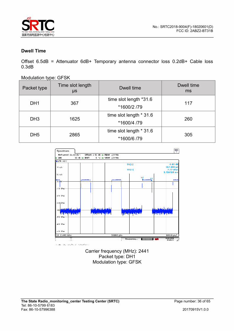
Dwell Time
Offset 6.5dB = Attenuator 6dB+ Temporary antenna connector loss 0.2dB+ Cable loss 0.3dB Modulation type: GFSK
Packet type Time slot length
µs Dwell time
Dwell time ms
DH1 367 time slot length *31.6
*1600/2 /79 117
DH3 1625 time slot length * 31.6
*1600/4 /79 260
DH5 2865 time slot length * 31.6
*1600/6 /79 305
Carrier frequency (MHz): 2441
Packet type: DH1 Modulation type: GFSK

No.: SRTC2018-9004(F)-18020601(D) FCC ID: 2ABZ2-BT31B
The State Radio_monitoring_center Testing Center (SRTC) Page number: 37 of 65
Tel: 86-10-5799 6183 Fax: 86-10-57996388 20170915V1.0.0
Carrier frequency (MHz): 2441
Packet type: DH3 Modulation type: GFSK
Carrier frequency (MHz): 2441
Packet type: DH5 Modulation type: GFSK
No.: SRTC2018-9004(F)-18020601(D) FCC ID: 2ABZ2-BT31B
The State Radio_monitoring_center Testing Center (SRTC) Page number: 38 of 65
Tel: 86-10-5799 6183 Fax: 86-10-57996388 20170915V1.0.0
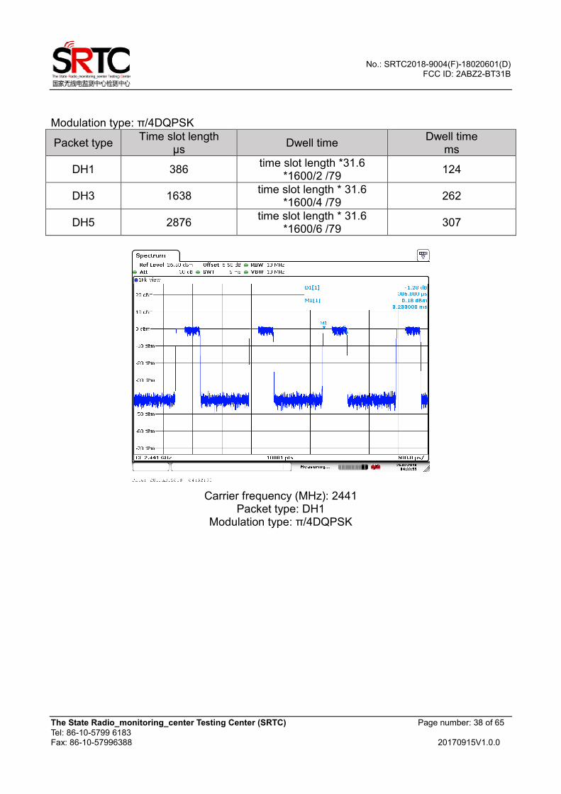
Modulation type: π/4DQPSK
Packet type Time slot length
µs Dwell time
Dwell time ms
DH1 386 time slot length *31.6
*1600/2 /79 124
DH3 1638 time slot length * 31.6
*1600/4 /79 262
DH5 2876 time slot length * 31.6
*1600/6 /79 307
Carrier frequency (MHz): 2441
Packet type: DH1 Modulation type: π/4DQPSK
No.: SRTC2018-9004(F)-18020601(D) FCC ID: 2ABZ2-BT31B
The State Radio_monitoring_center Testing Center (SRTC) Page number: 39 of 65
Tel: 86-10-5799 6183 Fax: 86-10-57996388 20170915V1.0.0
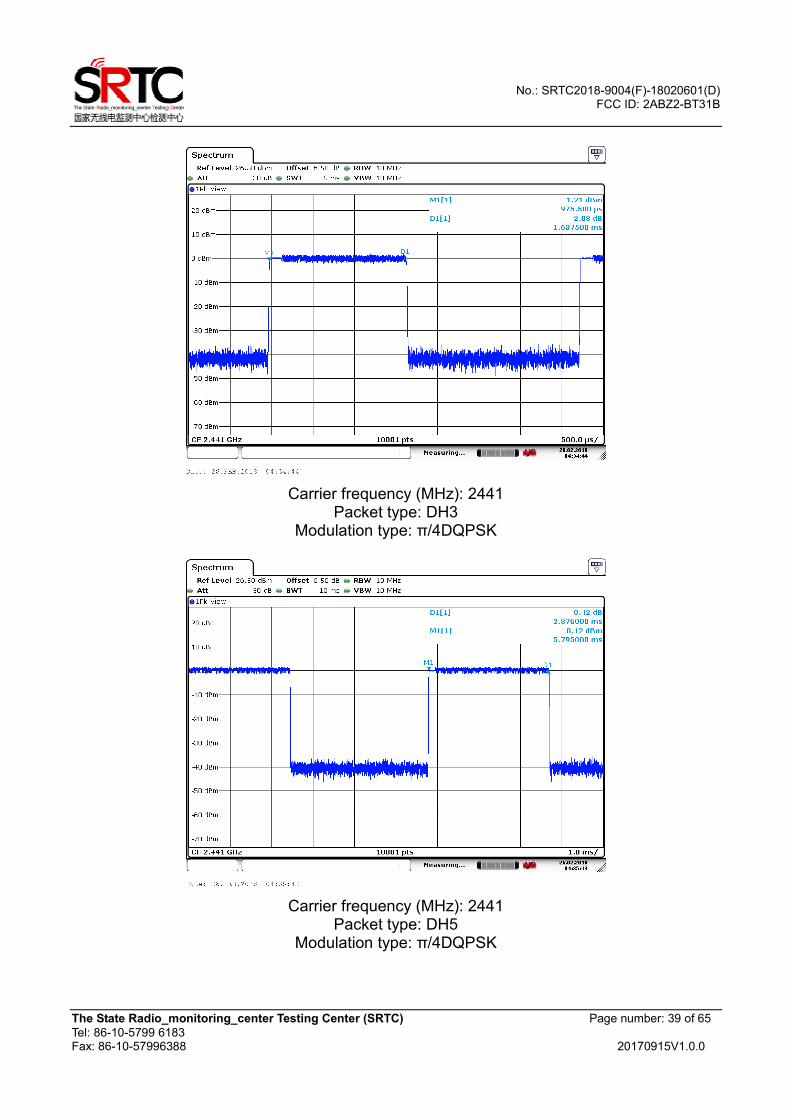
Carrier frequency (MHz): 2441
Packet type: DH3 Modulation type: π/4DQPSK
Carrier frequency (MHz): 2441
Packet type: DH5 Modulation type: π/4DQPSK
No.: SRTC2018-9004(F)-18020601(D) FCC ID: 2ABZ2-BT31B
The State Radio_monitoring_center Testing Center (SRTC) Page number: 40 of 65
Tel: 86-10-5799 6183 Fax: 86-10-57996388 20170915V1.0.0
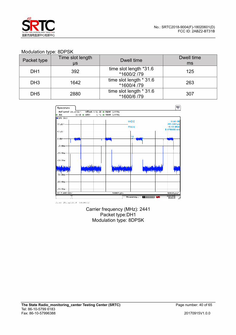
Modulation type: 8DPSK
Packet type Time slot length
µs Dwell time
Dwell time ms
DH1 392 time slot length *31.6
*1600/2 /79 125
DH3 1642 time slot length * 31.6
*1600/4 /79 263
DH5 2880 time slot length * 31.6
*1600/6 /79 307
Carrier frequency (MHz): 2441
Packet type:DH1 Modulation type: 8DPSK
No.: SRTC2018-9004(F)-18020601(D) FCC ID: 2ABZ2-BT31B
The State Radio_monitoring_center Testing Center (SRTC) Page number: 41 of 65
Tel: 86-10-5799 6183 Fax: 86-10-57996388 20170915V1.0.0
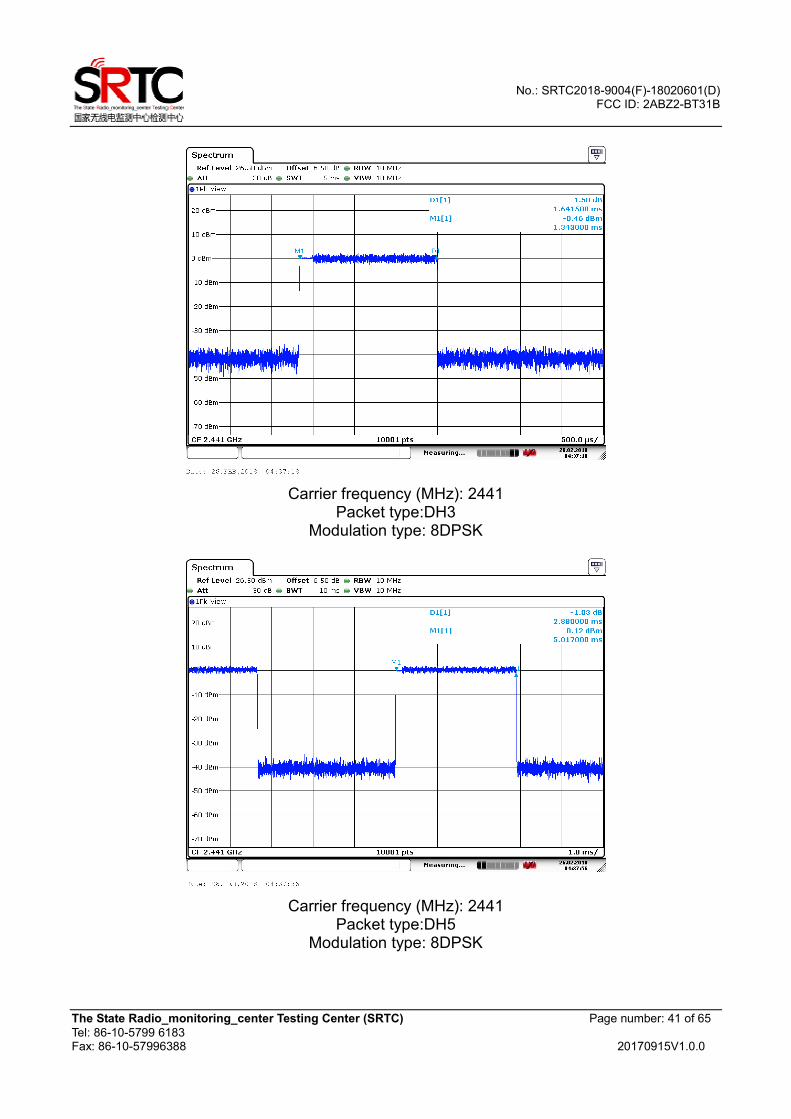
Carrier frequency (MHz): 2441
Packet type:DH3 Modulation type: 8DPSK
Carrier frequency (MHz): 2441
Packet type:DH5 Modulation type: 8DPSK
No.: SRTC2018-9004(F)-18020601(D) FCC ID: 2ABZ2-BT31B
The State Radio_monitoring_center Testing Center (SRTC) Page number: 42 of 65
Tel: 86-10-5799 6183 Fax: 86-10-57996388 20170915V1.0.0
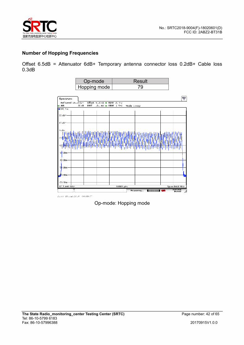
Number of Hopping Frequencies
Offset 6.5dB = Attenuator 6dB+ Temporary antenna connector loss 0.2dB+ Cable loss 0.3dB
Op-mode Result
Hopping mode 79
Op-mode: Hopping mode
No.: SRTC2018-9004(F)-18020601(D) FCC ID: 2ABZ2-BT31B
The State Radio_monitoring_center Testing Center (SRTC) Page number: 43 of 65
Tel: 86-10-5799 6183 Fax: 86-10-57996388 20170915V1.0.0
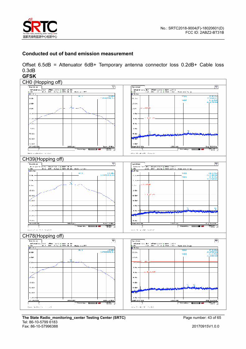
Conducted out of band emission measurement
Offset 6.5dB = Attenuator 6dB+ Temporary antenna connector loss 0.2dB+ Cable loss 0.3dB GFSK
CH0 (Hopping off)
CH39(Hopping off)
CH78(Hopping off)

No.: SRTC2018-9004(F)-18020601(D) FCC ID: 2ABZ2-BT31B
The State Radio_monitoring_center Testing Center (SRTC) Page number: 44 of 65
Tel: 86-10-5799 6183 Fax: 86-10-57996388 20170915V1.0.0
π/4DQPSK
CH0 (Hopping off)
CH39(Hopping off)
CH78(Hopping off)
No.: SRTC2018-9004(F)-18020601(D) FCC ID: 2ABZ2-BT31B
The State Radio_monitoring_center Testing Center (SRTC) Page number: 45 of 65
Tel: 86-10-5799 6183 Fax: 86-10-57996388 20170915V1.0.0
8DPSK
CH0 (Hopping off)
CH39(Hopping off)
CH78(Hopping off)
No.: SRTC2018-9004(F)-18020601(D) FCC ID: 2ABZ2-BT31B
The State Radio_monitoring_center Testing Center (SRTC) Page number: 46 of 65
Tel: 86-10-5799 6183 Fax: 86-10-57996388 20170915V1.0.0
Band Edge measurement
Offset 6.5dB = Attenuator 6dB+ Temporary antenna connector loss 0.2dB+ Cable loss 0.3dB GFSK
CH0 (Hopping off)
CH78(Hopping off)
CH0 (Hopping on) CH78 (Hopping on)
No.: SRTC2018-9004(F)-18020601(D) FCC ID: 2ABZ2-BT31B
The State Radio_monitoring_center Testing Center (SRTC) Page number: 47 of 65
Tel: 86-10-5799 6183 Fax: 86-10-57996388 20170915V1.0.0
π/4DQPSK
CH0 (Hopping off)
CH78(Hopping off)
CH0 (Hopping on) CH78 (Hopping on)
No.: SRTC2018-9004(F)-18020601(D) FCC ID: 2ABZ2-BT31B
The State Radio_monitoring_center Testing Center (SRTC) Page number: 48 of 65
Tel: 86-10-5799 6183 Fax: 86-10-57996388 20170915V1.0.0
8DPSK
CH0 (Hopping off)
CH78(Hopping off)
CH0 (Hopping on) CH78 (Hopping on)
No.: SRTC2018-9004(F)-18020601(D) FCC ID: 2ABZ2-BT31B
The State Radio_monitoring_center Testing Center (SRTC) Page number: 49 of 65
Tel: 86-10-5799 6183 Fax: 86-10-57996388 20170915V1.0.0
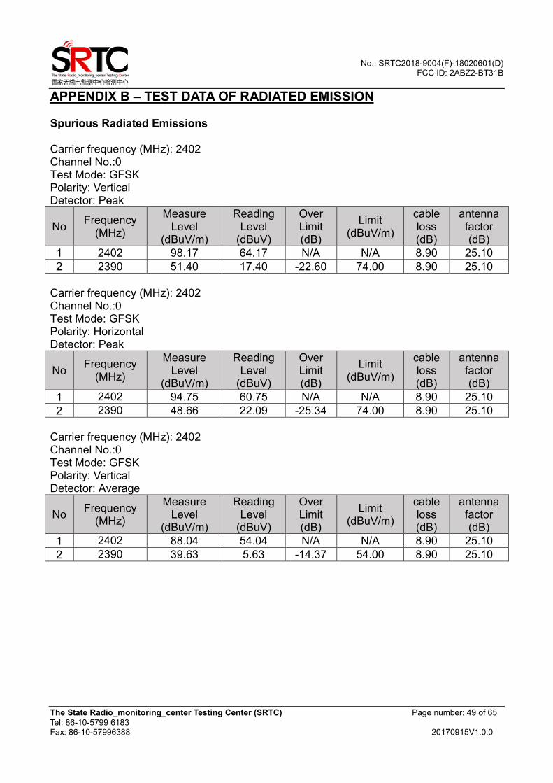
APPENDIX B – TEST DATA OF RADIATED EMISSION Spurious Radiated Emissions Carrier frequency (MHz): 2402 Channel No.:0 Test Mode: GFSK Polarity: Vertical Detector: Peak
No Frequency
(MHz)
Measure Level
(dBuV/m)
Reading Level
(dBuV)
Over Limit (dB)
Limit (dBuV/m)
cable loss (dB)
antenna factor (dB)
1 2402 98.17 64.17 N/A N/A 8.90 25.10
2 2390 51.40 17.40 -22.60 74.00 8.90 25.10
Carrier frequency (MHz): 2402 Channel No.:0 Test Mode: GFSK Polarity: Horizontal Detector: Peak
No Frequency
(MHz)
Measure Level
(dBuV/m)
Reading Level
(dBuV)
Over Limit (dB)
Limit (dBuV/m)
cable loss (dB)
antenna factor (dB)
1 2402 94.75 60.75 N/A N/A 8.90 25.10
2 2390 48.66 22.09 -25.34 74.00 8.90 25.10
Carrier frequency (MHz): 2402 Channel No.:0 Test Mode: GFSK Polarity: Vertical Detector: Average
No Frequency
(MHz)
Measure Level
(dBuV/m)
Reading Level
(dBuV)
Over Limit (dB)
Limit (dBuV/m)
cable loss (dB)
antenna factor (dB)
1 2402 88.04 54.04 N/A N/A 8.90 25.10
2 2390 39.63 5.63 -14.37 54.00 8.90 25.10
No.: SRTC2018-9004(F)-18020601(D) FCC ID: 2ABZ2-BT31B
The State Radio_monitoring_center Testing Center (SRTC) Page number: 50 of 65
Tel: 86-10-5799 6183 Fax: 86-10-57996388 20170915V1.0.0
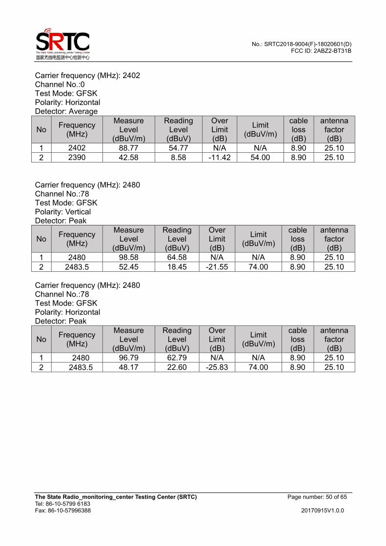
Carrier frequency (MHz): 2402 Channel No.:0 Test Mode: GFSK Polarity: Horizontal Detector: Average
No Frequency
(MHz)
Measure Level
(dBuV/m)
Reading Level
(dBuV)
Over Limit (dB)
Limit (dBuV/m)
cable loss (dB)
antenna factor (dB)
1 2402 88.77 54.77 N/A N/A 8.90 25.10
2 2390 42.58 8.58 -11.42 54.00 8.90 25.10
Carrier frequency (MHz): 2480 Channel No.:78 Test Mode: GFSK Polarity: Vertical Detector: Peak
No Frequency
(MHz)
Measure Level
(dBuV/m)
Reading Level
(dBuV)
Over Limit (dB)
Limit (dBuV/m)
cable loss (dB)
antenna factor (dB)
1 2480 98.58 64.58 N/A N/A 8.90 25.10
2 2483.5 52.45 18.45 -21.55 74.00 8.90 25.10
Carrier frequency (MHz): 2480 Channel No.:78 Test Mode: GFSK Polarity: Horizontal Detector: Peak
No Frequency
(MHz)
Measure Level
(dBuV/m)
Reading Level
(dBuV)
Over Limit (dB)
Limit (dBuV/m)
cable loss (dB)
antenna factor (dB)
1 2480 96.79 62.79 N/A N/A 8.90 25.10
2 2483.5 48.17 22.60 -25.83 74.00 8.90 25.10
No.: SRTC2018-9004(F)-18020601(D) FCC ID: 2ABZ2-BT31B
The State Radio_monitoring_center Testing Center (SRTC) Page number: 51 of 65
Tel: 86-10-5799 6183 Fax: 86-10-57996388 20170915V1.0.0
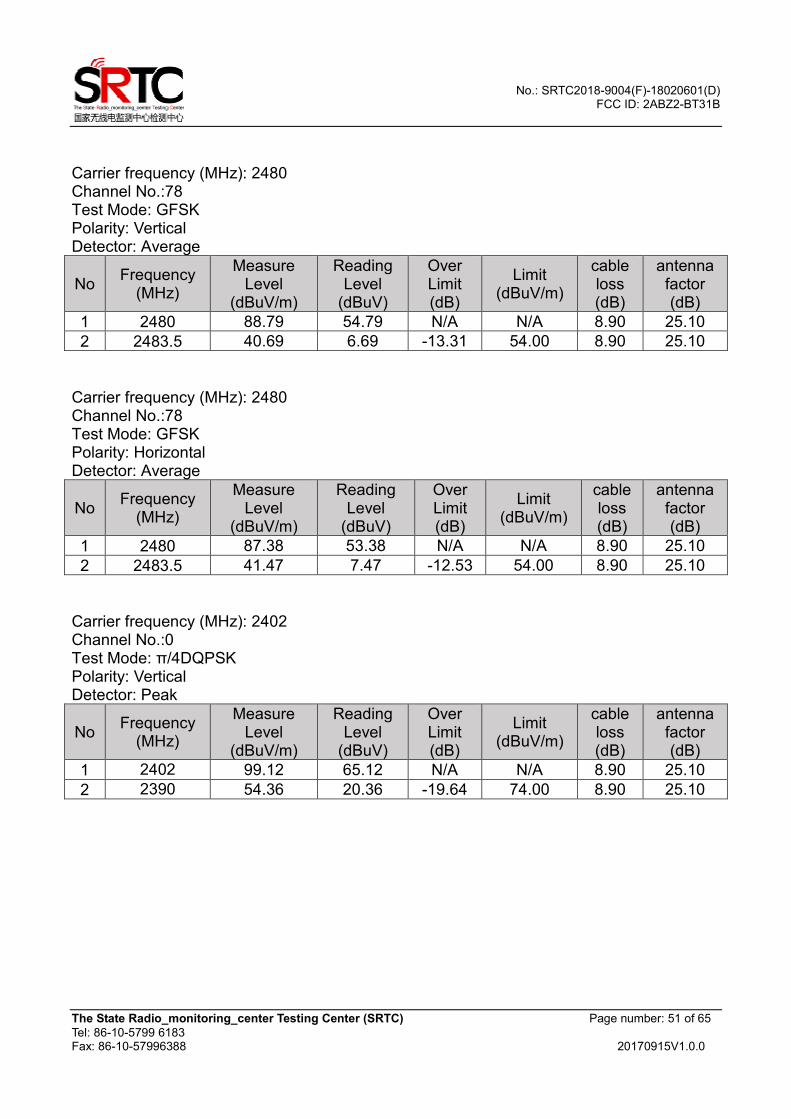
Carrier frequency (MHz): 2480 Channel No.:78 Test Mode: GFSK Polarity: Vertical Detector: Average
No Frequency
(MHz)
Measure Level
(dBuV/m)
Reading Level
(dBuV)
Over Limit (dB)
Limit (dBuV/m)
cable loss (dB)
antenna factor (dB)
1 2480 88.79 54.79 N/A N/A 8.90 25.10
2 2483.5 40.69 6.69 -13.31 54.00 8.90 25.10
Carrier frequency (MHz): 2480 Channel No.:78 Test Mode: GFSK Polarity: Horizontal Detector: Average
No Frequency
(MHz)
Measure Level
(dBuV/m)
Reading Level
(dBuV)
Over Limit (dB)
Limit (dBuV/m)
cable loss (dB)
antenna factor (dB)
1 2480 87.38 53.38 N/A N/A 8.90 25.10
2 2483.5 41.47 7.47 -12.53 54.00 8.90 25.10
Carrier frequency (MHz): 2402 Channel No.:0 Test Mode: π/4DQPSK Polarity: Vertical Detector: Peak
No Frequency
(MHz)
Measure Level
(dBuV/m)
Reading Level
(dBuV)
Over Limit (dB)
Limit (dBuV/m)
cable loss (dB)
antenna factor (dB)
1 2402 99.12 65.12 N/A N/A 8.90 25.10
2 2390 54.36 20.36 -19.64 74.00 8.90 25.10
No.: SRTC2018-9004(F)-18020601(D) FCC ID: 2ABZ2-BT31B
The State Radio_monitoring_center Testing Center (SRTC) Page number: 52 of 65
Tel: 86-10-5799 6183 Fax: 86-10-57996388 20170915V1.0.0
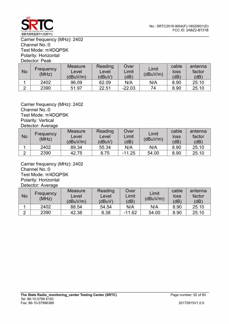
Carrier frequency (MHz): 2402 Channel No.:0 Test Mode: π/4DQPSK Polarity: Horizontal Detector: Peak
No Frequency
(MHz)
Measure Level
(dBuV/m)
Reading Level
(dBuV)
Over Limit (dB)
Limit (dBuV/m)
cable loss (dB)
antenna factor (dB)
1 2402 96.09 62.09 N/A N/A 8.90 25.10
2 2390 51.97 22.51 -22.03 74 8.90 25.10
Carrier frequency (MHz): 2402 Channel No.:0 Test Mode: π/4DQPSK Polarity: Vertical Detector: Average
No Frequency
(MHz)
Measure Level
(dBuV/m)
Reading Level
(dBuV)
Over Limit (dB)
Limit (dBuV/m)
cable loss (dB)
antenna factor (dB)
1 2402 89.34 55.34 N/A N/A 8.90 25.10
2 2390 42.75 8.75 -11.25 54.00 8.90 25.10
Carrier frequency (MHz): 2402 Channel No.:0 Test Mode: π/4DQPSK Polarity: Horizontal Detector: Average
No Frequency
(MHz)
Measure Level
(dBuV/m)
Reading Level
(dBuV)
Over Limit (dB)
Limit (dBuV/m)
cable loss (dB)
antenna factor (dB)
1 2402 88.54 54.54 N/A N/A 8.90 25.10
2 2390 42.38 8.38 -11.62 54.00 8.90 25.10
No.: SRTC2018-9004(F)-18020601(D) FCC ID: 2ABZ2-BT31B
The State Radio_monitoring_center Testing Center (SRTC) Page number: 53 of 65
Tel: 86-10-5799 6183 Fax: 86-10-57996388 20170915V1.0.0
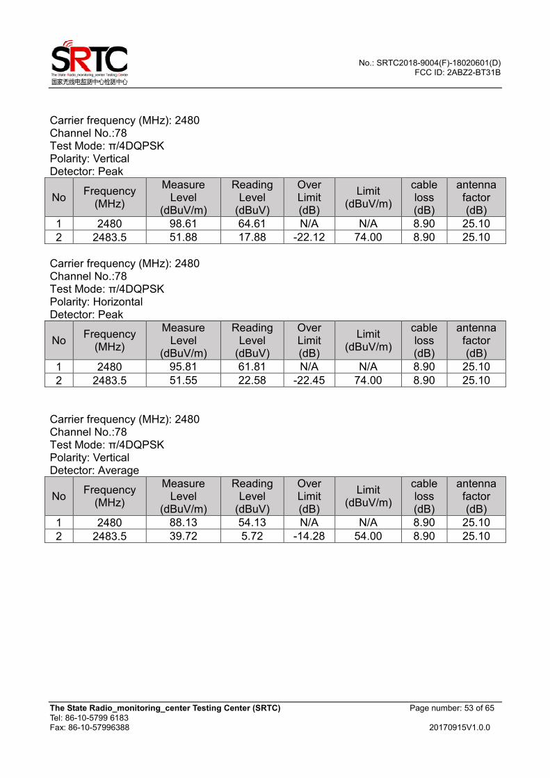
Carrier frequency (MHz): 2480 Channel No.:78 Test Mode: π/4DQPSK Polarity: Vertical Detector: Peak
No Frequency
(MHz)
Measure Level
(dBuV/m)
Reading Level
(dBuV)
Over Limit (dB)
Limit (dBuV/m)
cable loss (dB)
antenna factor (dB)
1 2480 98.61 64.61 N/A N/A 8.90 25.10
2 2483.5 51.88 17.88 -22.12 74.00 8.90 25.10
Carrier frequency (MHz): 2480 Channel No.:78 Test Mode: π/4DQPSK Polarity: Horizontal Detector: Peak
No Frequency
(MHz)
Measure Level
(dBuV/m)
Reading Level
(dBuV)
Over Limit (dB)
Limit (dBuV/m)
cable loss (dB)
antenna factor (dB)
1 2480 95.81 61.81 N/A N/A 8.90 25.10
2 2483.5 51.55 22.58 -22.45 74.00 8.90 25.10
Carrier frequency (MHz): 2480 Channel No.:78 Test Mode: π/4DQPSK Polarity: Vertical Detector: Average
No Frequency
(MHz)
Measure Level
(dBuV/m)
Reading Level
(dBuV)
Over Limit (dB)
Limit (dBuV/m)
cable loss (dB)
antenna factor (dB)
1 2480 88.13 54.13 N/A N/A 8.90 25.10
2 2483.5 39.72 5.72 -14.28 54.00 8.90 25.10
No.: SRTC2018-9004(F)-18020601(D) FCC ID: 2ABZ2-BT31B
The State Radio_monitoring_center Testing Center (SRTC) Page number: 54 of 65
Tel: 86-10-5799 6183 Fax: 86-10-57996388 20170915V1.0.0
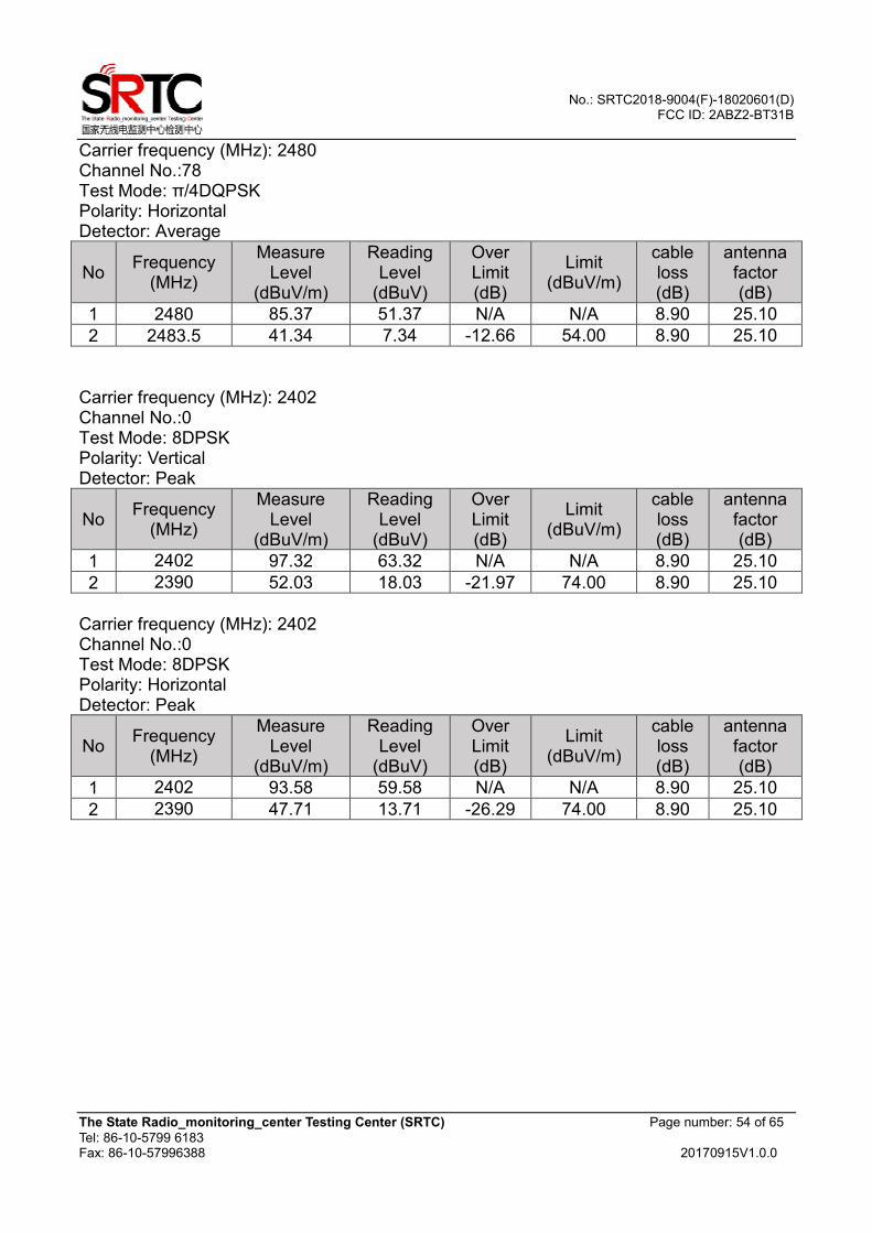
Carrier frequency (MHz): 2480 Channel No.:78 Test Mode: π/4DQPSK Polarity: Horizontal Detector: Average
No Frequency
(MHz)
Measure Level
(dBuV/m)
Reading Level
(dBuV)
Over Limit (dB)
Limit (dBuV/m)
cable loss (dB)
antenna factor (dB)
1 2480 85.37 51.37 N/A N/A 8.90 25.10
2 2483.5 41.34 7.34 -12.66 54.00 8.90 25.10
Carrier frequency (MHz): 2402 Channel No.:0 Test Mode: 8DPSK Polarity: Vertical Detector: Peak
No Frequency
(MHz)
Measure Level
(dBuV/m)
Reading Level
(dBuV)
Over Limit (dB)
Limit (dBuV/m)
cable loss (dB)
antenna factor (dB)
1 2402 97.32 63.32 N/A N/A 8.90 25.10
2 2390 52.03 18.03 -21.97 74.00 8.90 25.10
Carrier frequency (MHz): 2402 Channel No.:0 Test Mode: 8DPSK Polarity: Horizontal Detector: Peak
No Frequency
(MHz)
Measure Level
(dBuV/m)
Reading Level
(dBuV)
Over Limit (dB)
Limit (dBuV/m)
cable loss (dB)
antenna factor (dB)
1 2402 93.58 59.58 N/A N/A 8.90 25.10
2 2390 47.71 13.71 -26.29 74.00 8.90 25.10

No.: SRTC2018-9004(F)-18020601(D) FCC ID: 2ABZ2-BT31B
The State Radio_monitoring_center Testing Center (SRTC) Page number: 55 of 65
Tel: 86-10-5799 6183 Fax: 86-10-57996388 20170915V1.0.0
Carrier frequency (MHz): 2402 Channel No.:0 Test Mode: 8DPSK Polarity: Vertical Detector: Average
No Frequency
(MHz)
Measure Level
(dBuV/m)
Reading Level
(dBuV)
Over Limit (dB)
Limit (dBuV/m)
cable loss (dB)
antenna factor (dB)
1 2402 88.05 54.05 N/A N/A 8.90 25.10
2 2390 42.82 8.82 -11.18 54.00 8.90 25.10
Carrier frequency (MHz): 2402 Channel No.:0 Test Mode: 8DPSK Polarity: Horizontal Detector: Average
No Frequency
(MHz)
Measure Level
(dBuV/m)
Reading Level
(dBuV)
Over Limit (dB)
Limit (dBuV/m)
cable loss (dB)
antenna factor (dB)
1 2402 87.38 53.38 N/A N/A 8.90 25.10
2 2390 41.06 7.06 -12.94 54.00 8.90 25.10
Carrier frequency (MHz): 2480 Channel No.:78 Test Mode: 8DPSK Polarity: Vertical Detector: Peak
No Frequency
(MHz)
Measure Level
(dBuV/m)
Reading Level
(dBuV)
Over Limit (dB)
Limit (dBuV/m)
cable loss (dB)
antenna factor (dB)
1 2480 97.35 63.35 N/A N/A 8.90 25.10
2 2483.5 50.40 16.40 -23.60 74.00 8.90 25.10
Carrier frequency (MHz): 2480 Channel No.:78 Test Mode: 8DPSK Polarity: Horizontal Detector: Peak
No Frequency
(MHz)
Measure Level
(dBuV/m)
Reading Level
(dBuV)
Over Limit (dB)
Limit (dBuV/m)
cable loss (dB)
antenna factor (dB)
1 2480 93.30 59.30 N/A N/A 8.90 25.10
2 2483.5 46.03 12.03 -27.97 74.00 8.90 25.10
No.: SRTC2018-9004(F)-18020601(D) FCC ID: 2ABZ2-BT31B
The State Radio_monitoring_center Testing Center (SRTC) Page number: 56 of 65
Tel: 86-10-5799 6183 Fax: 86-10-57996388 20170915V1.0.0
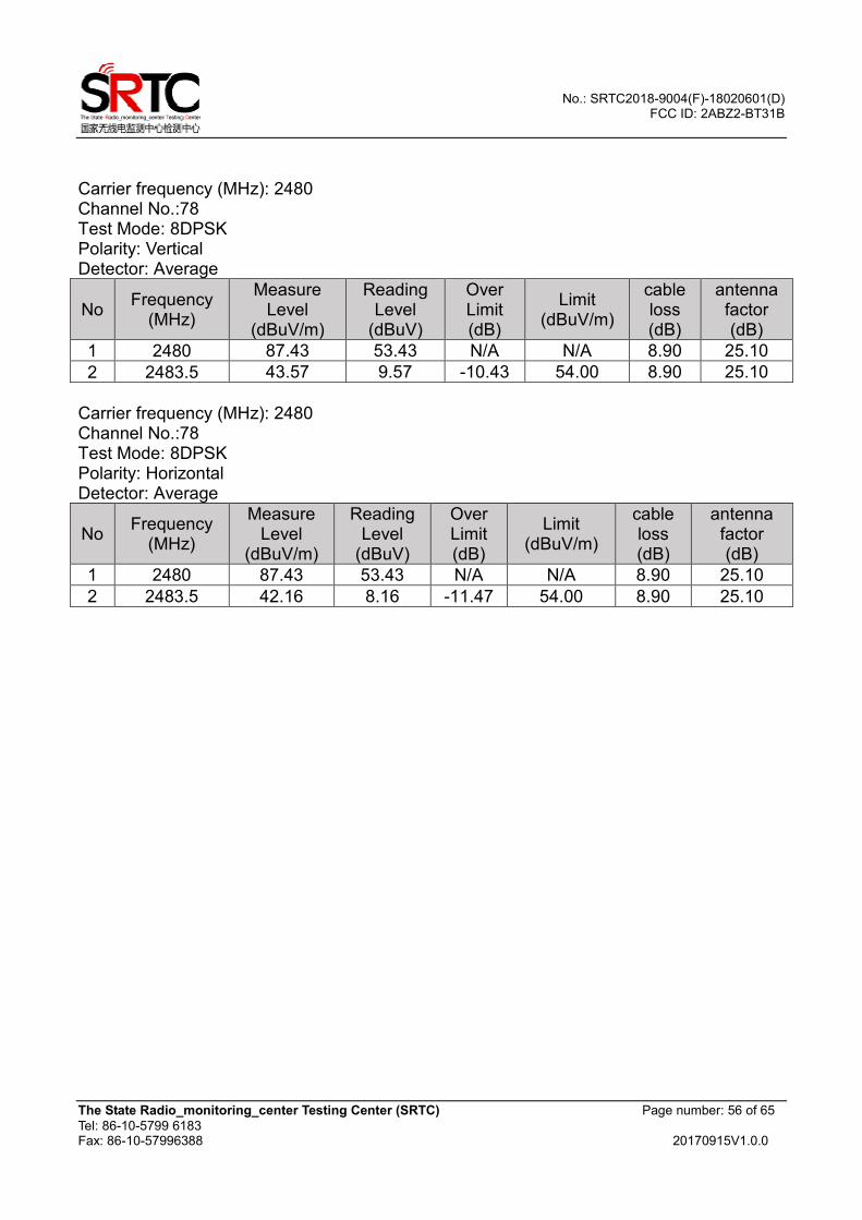
Carrier frequency (MHz): 2480 Channel No.:78 Test Mode: 8DPSK Polarity: Vertical Detector: Average
No Frequency
(MHz)
Measure Level
(dBuV/m)
Reading Level
(dBuV)
Over Limit (dB)
Limit (dBuV/m)
cable loss (dB)
antenna factor (dB)
1 2480 87.43 53.43 N/A N/A 8.90 25.10
2 2483.5 43.57 9.57 -10.43 54.00 8.90 25.10
Carrier frequency (MHz): 2480 Channel No.:78 Test Mode: 8DPSK Polarity: Horizontal Detector: Average
No Frequency
(MHz)
Measure Level
(dBuV/m)
Reading Level
(dBuV)
Over Limit (dB)
Limit (dBuV/m)
cable loss (dB)
antenna factor (dB)
1 2480 87.43 53.43 N/A N/A 8.90 25.10
2 2483.5 42.16 8.16 -11.47 54.00 8.90 25.10
No.: SRTC2018-9004(F)-18020601(D) FCC ID: 2ABZ2-BT31B
The State Radio_monitoring_center Testing Center (SRTC) Page number: 57 of 65
Tel: 86-10-5799 6183 Fax: 86-10-57996388 20170915V1.0.0
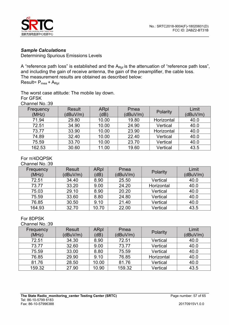
Sample Calculations Determining Spurious Emissions Levels A “reference path loss” is established and the ARpl is the attenuation of “reference path loss”, and including the gain of receive antenna, the gain of the preamplifier, the cable loss. The measurement results are obtained as described below: Result= Pmea + ARpl
The worst case attitude: The mobile lay down. For GFSK Channel No.:39
Frequency (MHz)
Result (dBuV/m)
ARpl (dB)
Pmea (dBuV/m)
Polarity Limit
(dBuV/m)
71.94 29.80 10.00 19.80 Horizontal 40.0
72.51 34.90 10.00 24.90 Vertical 40.0
73.77 33.90 10.00 23.90 Horizontal 40.0
74.89 32.40 10.00 22.40 Vertical 40.0
75.59 33.70 10.00 23.70 Vertical 40.0
162.53 30.60 11.00 19.60 Vertical 43.5
For π/4DQPSK Channel No.:39
Frequency (MHz)
Result (dBuV/m)
ARpl (dB)
Pmea (dBuV/m)
Polarity Limit
(dBuV/m)
72.51 34.40 8.90 25.50 Vertical 40.0
73.77 33.20 9.00 24.20 Horizontal 40.0
75.03 29.10 8.90 20.20 Vertical 40.0
75.59 33.60 8.80 24.80 Vertical 40.0
76.85 30.50 9.10 21.40 Vertical 40.0
164.93 32.70 10.70 22.00 Vertical 43.5
For 8DPSK Channel No.:39
Frequency (MHz)
Result (dBuV/m)
ARpl (dB)
Pmea (dBuV/m)
Polarity Limit
(dBuV/m)
72.51 34.30 8.90 72.51 Vertical 40.0
73.77 32.60 9.00 73.77 Vertical 40.0
75.59 33.00 8.80 75.59 Vertical 40.0
76.85 29.90 9.10 76.85 Horizontal 40.0
81.76 28.50 10.00 81.76 Vertical 40.0
159.32 27.90 10.90 159.32 Vertical 43.5
No.: SRTC2018-9004(F)-18020601(D) FCC ID: 2ABZ2-BT31B
The State Radio_monitoring_center Testing Center (SRTC) Page number: 58 of 65
Tel: 86-10-5799 6183 Fax: 86-10-57996388 20170915V1.0.0
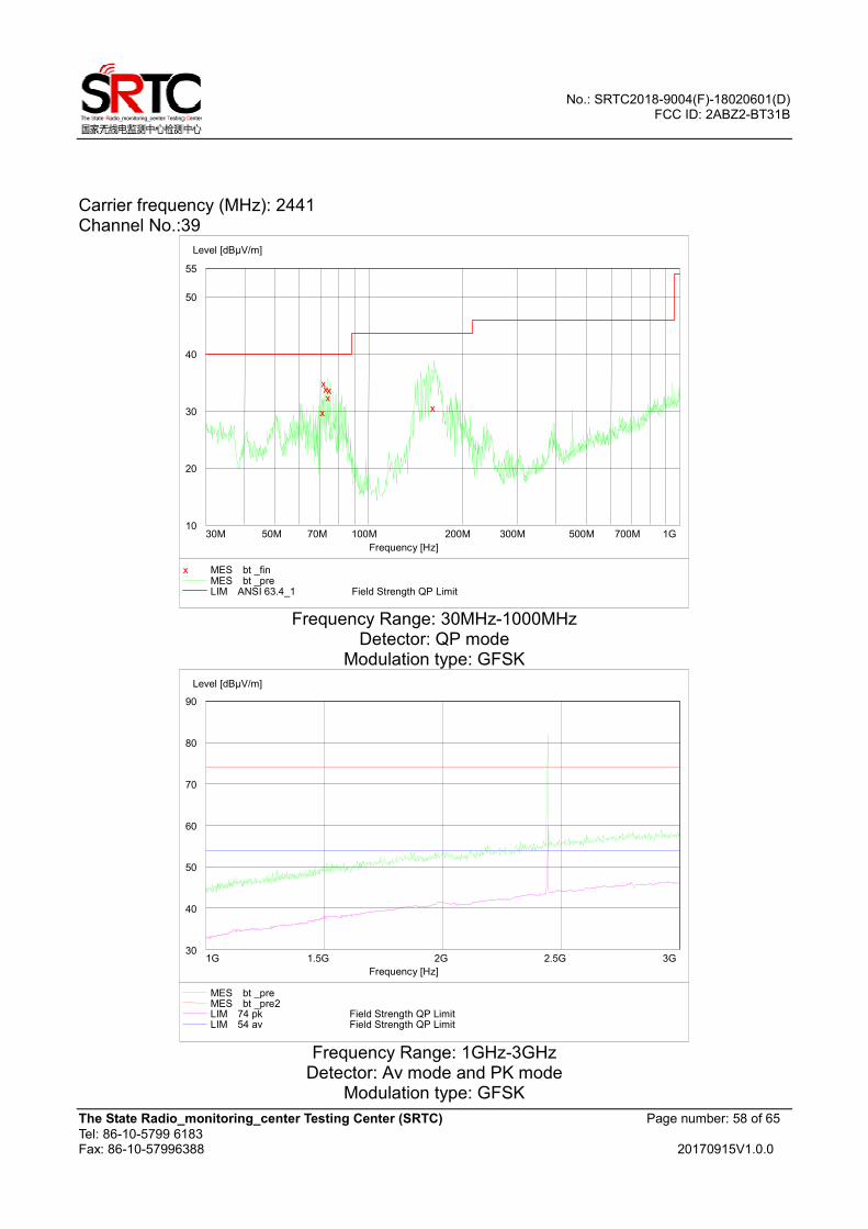
Carrier frequency (MHz): 2441
Channel No.:39
Frequency Range: 30MHz-1000MHz
Detector: QP mode Modulation type: GFSK
Frequency Range: 1GHz-3GHz
Detector: Av mode and PK mode Modulation type: GFSK
10
20
30
40
50
55
Level [dBµV/m]
30M 50M 70M 100M 200M 300M 500M 700M 1G
Frequency [Hz]
x
x x x x
x
x MES bt _fin MES bt _pre LIM ANSI 63.4_1 Field Strength QP Limit
30
40
50
60
70
80
90
Level [dBµV/m]
1G 1.5G 2G 2.5G 3G
Frequency [Hz]
MES bt _pre MES bt _pre2 LIM 74 pk Field Strength QP LimitLIM 54 av Field Strength QP Limit
No.: SRTC2018-9004(F)-18020601(D) FCC ID: 2ABZ2-BT31B
The State Radio_monitoring_center Testing Center (SRTC) Page number: 59 of 65
Tel: 86-10-5799 6183 Fax: 86-10-57996388 20170915V1.0.0
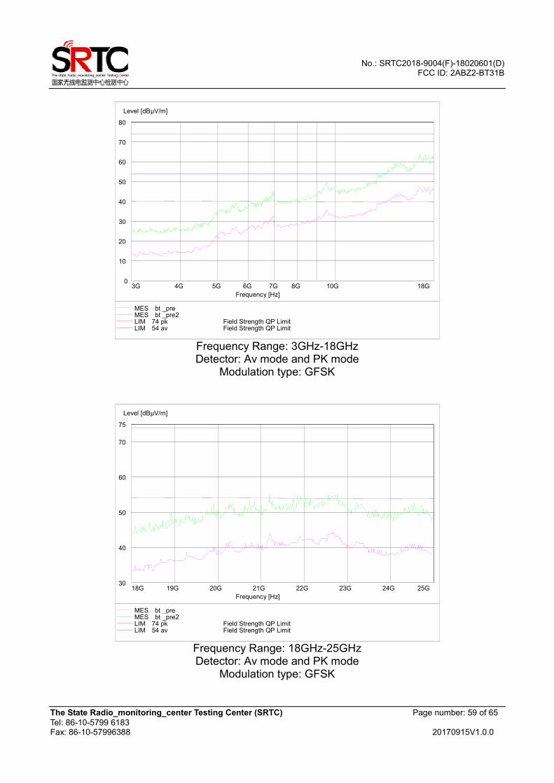
Frequency Range: 3GHz-18GHz Detector: Av mode and PK mode
Modulation type: GFSK
Frequency Range: 18GHz-25GHz Detector: Av mode and PK mode
Modulation type: GFSK
0
10
20
30
40
50
60
70
80
Level [dBµV/m]
3G 4G 5G 6G 7G 8G 10G 18G
Frequency [Hz]
MES bt _pre MES bt _pre2 LIM 74 pk Field Strength QP LimitLIM 54 av Field Strength QP Limit
30
40
50
60
70
75
Level [dBµV/m]
18G 19G 20G 21G 22G 23G 24G 25G
Frequency [Hz]
MES bt _pre MES bt _pre2 LIM 74 pk Field Strength QP LimitLIM 54 av Field Strength QP Limit
No.: SRTC2018-9004(F)-18020601(D) FCC ID: 2ABZ2-BT31B
The State Radio_monitoring_center Testing Center (SRTC) Page number: 60 of 65
Tel: 86-10-5799 6183 Fax: 86-10-57996388 20170915V1.0.0
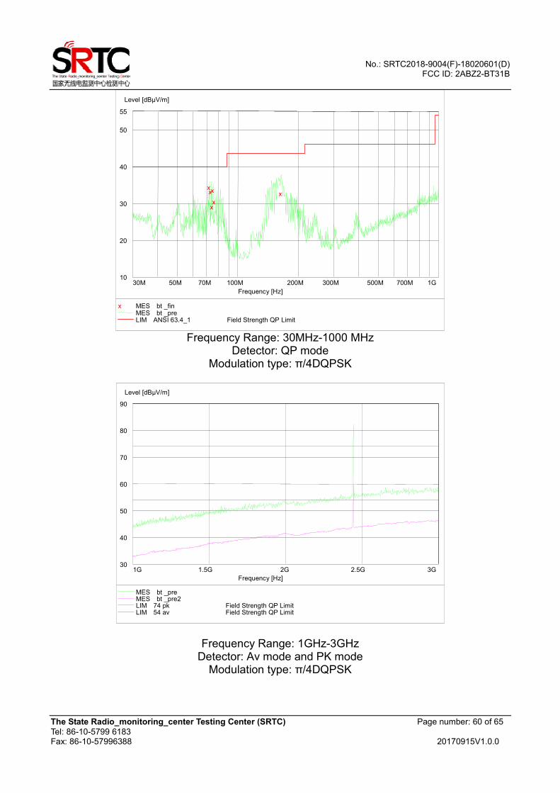
Frequency Range: 30MHz-1000 MHz
Detector: QP mode Modulation type: π/4DQPSK
Frequency Range: 1GHz-3GHz Detector: Av mode and PK mode
Modulation type: π/4DQPSK
10
20
30
40
50
55
Level [dBµV/m]
30M 50M 70M 100M 200M 300M 500M 700M 1G
Frequency [Hz]
x x
x
x
x x
x MES bt _fin MES bt _pre LIM ANSI 63.4_1 Field Strength QP Limit
30
40
50
60
70
80
90
Level [dBµV/m]
1G 1.5G 2G 2.5G 3G
Frequency [Hz]
MES bt _pre MES bt _pre2 LIM 74 pk Field Strength QP LimitLIM 54 av Field Strength QP Limit
No.: SRTC2018-9004(F)-18020601(D) FCC ID: 2ABZ2-BT31B
The State Radio_monitoring_center Testing Center (SRTC) Page number: 61 of 65
Tel: 86-10-5799 6183 Fax: 86-10-57996388 20170915V1.0.0
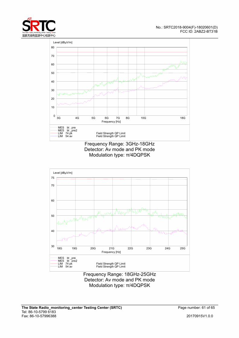
Frequency Range: 3GHz-18GHz Detector: Av mode and PK mode
Modulation type: π/4DQPSK
Frequency Range: 18GHz-25GHz Detector: Av mode and PK mode
Modulation type: π/4DQPSK
0
10
20
30
40
50
60
70
80
Level [dBµV/m]
3G 4G 5G 6G 7G 8G 10G 18G
Frequency [Hz]
MES bt _pre MES bt _pre2 LIM 74 pk Field Strength QP LimitLIM 54 av Field Strength QP Limit
30
40
50
60
70
75
Level [dBµV/m]
18G 19G 20G 21G 22G 23G 24G 25G
Frequency [Hz]
MES bt _pre MES bt _pre2 LIM 74 pk Field Strength QP LimitLIM 54 av Field Strength QP Limit
No.: SRTC2018-9004(F)-18020601(D) FCC ID: 2ABZ2-BT31B
The State Radio_monitoring_center Testing Center (SRTC) Page number: 62 of 65
Tel: 86-10-5799 6183 Fax: 86-10-57996388 20170915V1.0.0
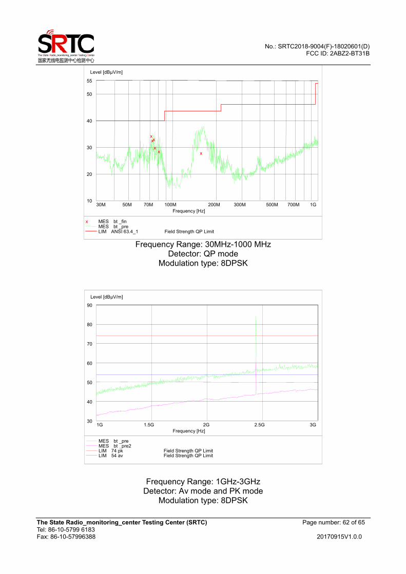
Frequency Range: 30MHz-1000 MHz
Detector: QP mode Modulation type: 8DPSK
Frequency Range: 1GHz-3GHz
Detector: Av mode and PK mode Modulation type: 8DPSK
10
20
30
40
50
55
Level [dBµV/m]
30M 50M 70M 100M 200M 300M 500M 700M 1G
Frequency [Hz]
x x x
x x x
x MES bt _fin MES bt _pre LIM ANSI 63.4_1 Field Strength QP Limit
30
40
50
60
70
80
90
Level [dBµV/m]
1G 1.5G 2G 2.5G 3G
Frequency [Hz]
MES bt _pre MES bt _pre2 LIM 74 pk Field Strength QP LimitLIM 54 av Field Strength QP Limit

No.: SRTC2018-9004(F)-18020601(D) FCC ID: 2ABZ2-BT31B
The State Radio_monitoring_center Testing Center (SRTC) Page number: 63 of 65
Tel: 86-10-5799 6183 Fax: 86-10-57996388 20170915V1.0.0
Frequency Range: 3GHz-18GHz Detector: Av mode and PK mode
Modulation type: 8DPSK
0
10
20
30
40
50
60
70
80
Level [dBµV/m]
3G 4G 5G 6G 7G 8G 10G 18G
Frequency [Hz]
MES bt _pre MES bt _pre2 LIM 74 pk Field Strength QP LimitLIM 54 av Field Strength QP Limit
No.: SRTC2018-9004(F)-18020601(D) FCC ID: 2ABZ2-BT31B
The State Radio_monitoring_center Testing Center (SRTC) Page number: 64 of 65
Tel: 86-10-5799 6183 Fax: 86-10-57996388 20170915V1.0.0
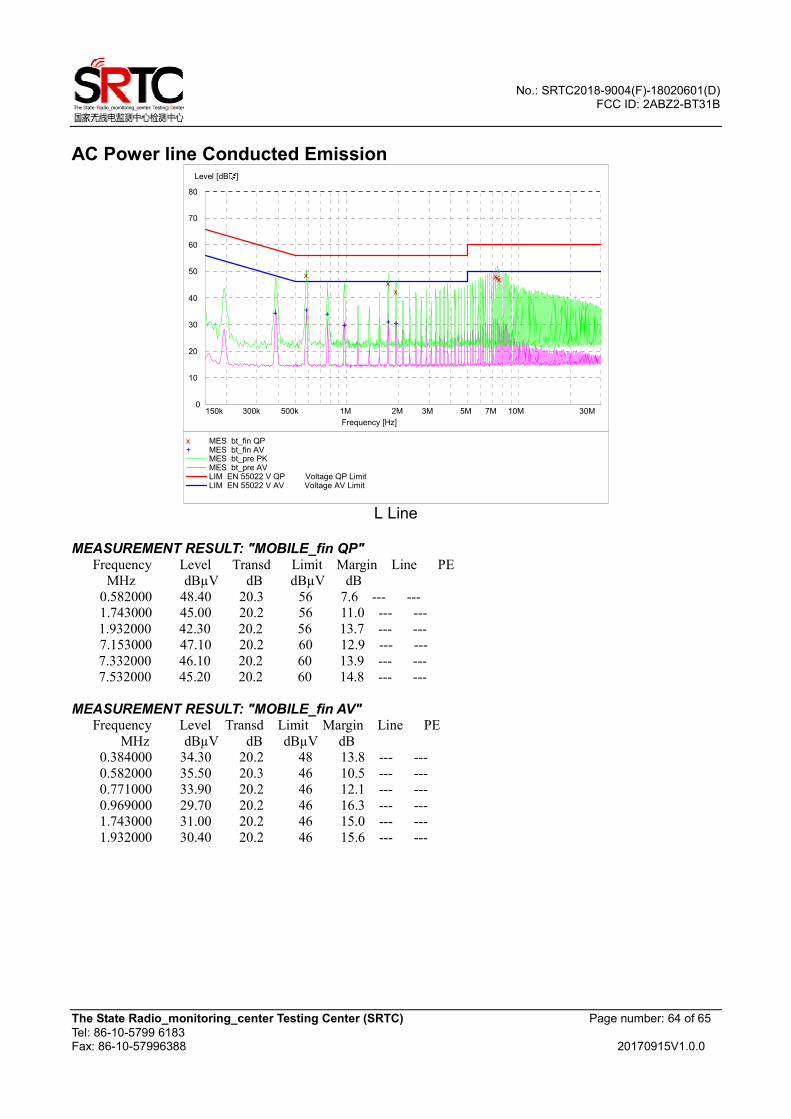
AC Power line Conducted Emission
0
10
20
30
40
50
60
70
80
礦Level [dB ]
150k 300k 500k 1M 2M 3M 5M 7M 10M 30M
Frequency [Hz]
+ ++
+ + +
xx
x
xxx
x MES bt_fin QP + MES bt_fin AV
MES bt_pre PK MES bt_pre AV LIM EN 55022 V QP Voltage QP LimitLIM EN 55022 V AV Voltage AV Limit
L Line
MEASUREMENT RESULT: "MOBILE_fin QP" Frequency Level Transd Limit Margin Line PE
MHz dBµV dB dBµV dB
0.582000 48.40 20.3 56 7.6 --- ---
1.743000 45.00 20.2 56 11.0 --- ---
1.932000 42.30 20.2 56 13.7 --- ---
7.153000 47.10 20.2 60 12.9 --- ---
7.332000 46.10 20.2 60 13.9 --- ---
7.532000 45.20 20.2 60 14.8 --- ---
MEASUREMENT RESULT: "MOBILE_fin AV" Frequency Level Transd Limit Margin Line PE
MHz dBµV dB dBµV dB
0.384000 34.30 20.2 48 13.8 --- ---
0.582000 35.50 20.3 46 10.5 --- ---
0.771000 33.90 20.2 46 12.1 --- ---
0.969000 29.70 20.2 46 16.3 --- ---
1.743000 31.00 20.2 46 15.0 --- ---
1.932000 30.40 20.2 46 15.6 --- ---
No.: SRTC2018-9004(F)-18020601(D) FCC ID: 2ABZ2-BT31B
The State Radio_monitoring_center Testing Center (SRTC) Page number: 65 of 65
Tel: 86-10-5799 6183 Fax: 86-10-57996388 20170915V1.0.0
0
10
20
30
40
50
60
70
80
礦Level [dB ]
150k 300k 500k 1M 2M 3M 5M 7M 10M 30M
Frequency [Hz]
+
+
++ + +
x
x
xx
x
x
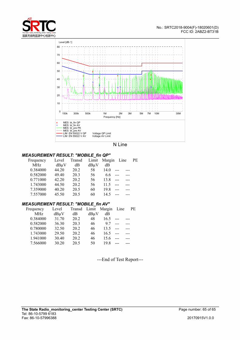
x MES bt_fin QP + MES bt_fin AV
MES bt_pre PK MES bt_pre AV LIM EN 55022 V QP Voltage QP LimitLIM EN 55022 V AV Voltage AV Limit
N Line
MEASUREMENT RESULT: "MOBILE_fin QP" Frequency Level Transd Limit Margin Line PE
MHz dBµV dB dBµV dB
0.384000 44.20 20.2 58 14.0 --- ---
0.582000 49.40 20.3 56 6.6 --- ---
0.771000 42.20 20.2 56 13.8 --- ---
1.743000 44.50 20.2 56 11.5 --- ---
7.359000 40.20 20.5 60 19.8 --- ---
7.557000 45.50 20.5 60 14.5 --- ---
MEASUREMENT RESULT: "MOBILE_fin AV" Frequency Level Transd Limit Margin Line PE
MHz dBµV dB dBµV dB
0.384000 31.70 20.2 48 16.5 --- ---
0.582000 36.30 20.3 46 9.7 --- ---
0.780000 32.50 20.2 46 13.5 --- ---
1.743000 29.50 20.2 46 16.5 --- ---
1.941000 30.40 20.2 46 15.6 --- ---
7.566000 30.20 20.5 50 19.8 --- ---
---End of Test Report---