Embed Size (px)
Citation preview
BNetzA-CAB-02/21-102
D-PL-12076-01-03
TEST REPORT
Test report no.: 1-2276/16-01-20-A
Testing laboratory Applicant
CTC advanced GmbH Untertuerkheimer Strasse 6 – 10 66117 Saarbruecken / Germany Phone: + 49 681 5 98 - 0 Fax: + 49 681 5 98 - 9075 Internet: http://www.ctcadvanced.com e-mail: [email protected]
Accredited Testing Laboratory: The testing laboratory (area of testing) is accredited according to DIN EN ISO/IEC 17025 (2005) by the Deutsche Akkreditierungsstelle GmbH (DAkkS) The accreditation is valid for the scope of testing procedures as stated in the accreditation certificate with the registration number: D-PL-12076-01-03
Alpina Watch International SA Route de la Galaise 8 1228 Plan-les-Quates / SWITZERLAND Phone: -/- Fax: -/- Contact: Guido Benedini e-mail: -/- Phone: +41 2 28 60 04 40
Manufacturer
Alpina Watch International SA Route de la Galaise 8 1228 Plan-les-Quates / SWITZERLAND
Test standard/s
47 CFR Part 15 Title 47 of the Code of Federal Regulations; Chapter I; Part 15 - Radio frequency devices
RSS - 247 Issue 2 Digital Transmission Systems (DTSs), Frequency Hopping Systems (FHSs) and
Licence - Exempt Local Area Network (LE-LAN) Devices
RSS - Gen Issue 4 Spectrum Management and Telecommunications Radio Standards Specifications - General Requirements and Information for the Certification of Radio Apparatus
For further applied test standards please refer to section 3 of this test report.
Test Item
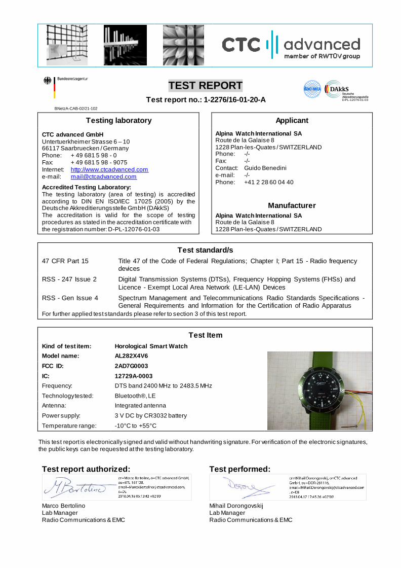
Kind of test item: Horological Smart Watch
Model name: AL282X4V6
FCC ID: 2AD7G0003
IC: 12729A-0003
Frequency: DTS band 2400 MHz to 2483.5 MHz
Technology tested: Bluetooth®, LE
Antenna: Integrated antenna
Power supply: 3 V DC by CR3032 battery
Temperature range: -10°C to +55°C
This test report is electronically signed and valid without handwriting signature. For verification of the electronic signatures, the public keys can be requested at the testing laboratory.
Test report authorized: Test performed:
Marco Bertolino Mihail Dorongovskij Lab Manager Lab Manager Radio Communications & EMC Radio Communications & EMC

Test report no.: 1-2276/16-01-20-A
Page 2 of 39
1 Table of contents
1 Table of contents................................................................................................................................. 2
2 General information ............................................................................................................................ 3
2.1 Notes and disclaimer ................................................................................................................ 3 2.2 Application details .................................................................................................................... 3 2.3 Test laboratories sub-contracted .............................................................................................. 3
3 Test standard/s and references ........................................................................................................... 4
4 Test environment ................................................................................................................................ 5
5 Test item ............................................................................................................................................. 5
5.1 General description................................................................................................................... 5 5.2 Additional information .............................................................................................................. 5
6 Description of the test setup ............................................................................................................... 6
6.1 Shielded semi anechoic chamber ............................................................................................. 7 6.2 Shielded fully anechoic chamber .............................................................................................. 8 6.3 Radiated measurements > 18 GHz ............................................................................................ 9
7 Sequence of testing .......................................................................................................................... 10
7.1 Sequence of testing radiated spurious 9 kHz to 30 MHz ......................................................... 10 7.2 Sequence of testing radiated spurious 30 MHz to 1 GHz ........................................................ 11 7.3 Sequence of testing radiated spurious 1 GHz to 18 GHz ......................................................... 12 7.4 Sequence of testing radiated spurious above 18 GHz ............................................................ 13
8 Measurement uncertainty.................................................................................................................. 14
9 Summary of measurement results .................................................................................................... 15
10 Additional comments..................................................................................................................... 16
11 Measurement results ..................................................................................................................... 17
11.1 System gain ......................................................................................................................... 17 11.2 Band edge compliance radiated .......................................................................................... 18 11.3 Spurious emissions radiated below 30 MHz ........................................................................ 20 11.4 Spurious emissions radiated 30 MHz to 1 GHz .................................................................... 23 11.5 Spurious emissions radiated above 1 GHz .......................................................................... 28
12 Observations ................................................................................................................................. 38
Annex A Document history ................................................................................................................ 38
Annex B Further information.............................................................................................................. 38
Annex C Accreditation Certificate ...................................................................................................... 39
Test report no.: 1-2276/16-01-20-A
Page 3 of 39
2 General information
2.1 Notes and disclaimer The test results of this test report relate exclusively to the test item specified in this test report. CTC advanced GmbH does not assume responsibility for any conclusions and generalizations drawn from the test results with
regard to other specimens or samples of the type of the equipment represented by the test item. The test report may only be reproduced or published in full. Reproduction or publication of extracts from the report requires the prior written approval of CTC advanced GmbH.
The testing service provided by CTC advanced GmbH has been rendered under the current "General Terms and Conditions for CTC advanced GmbH". CTC advanced GmbH will not be liable for any loss or damage resulting from false, inaccurate, inappropriate or
incomplete product information provided by the customer. Under no circumstances does the CTC advanced GmbH test report include any endorsement or warranty regarding the functionality, quality or performance of any other product or service provided.
Under no circumstances does the CTC advanced GmbH test report include or imply any product or service warranties from CTC advanced GmbH, including, without limitation, any implied warranties of merchantability, fitness for purpose, or non-infringement, all of which are expressly disclaimed by CTC advanced GmbH.
All rights and remedies regarding vendor’s products and services for which CTC advanced GmbH has prepared this test report shall be provided by the party offering such products or services and not by CTC advanced GmbH. In no case this test report can be considered as a Letter of Approval.
This test report is electronically signed and valid without handwritten signature. For verification of the electronic signatures, the public keys can be requested at the testing laboratory.
This test report replaces the test report with the number 1-2276/16-01-20 and dated 2017-01-10.
2.2 Application details Date of receipt of order: 2016-09-05
Date of receipt of test item: 2016-10-21 Start of test: 2016-12-21 End of test: 2017-01-10
Person(s) present during the test: -/-
2.3 Test laboratories sub-contracted
None
Test report no.: 1-2276/16-01-20-A
Page 4 of 39
3 Test standard/s and references Test standard Date Description
47 CFR Part 15 -/- Title 47 of the Code of Federal Regulations; Chapter I; Part 15 - Radio frequency devices
RSS - 247 Issue 2 February
2017
Digital Transmission Systems (DTSs), Frequency Hopping Systems (FHSs) and Licence - Exempt Local Area Network (LE-LAN) Devices
RSS - Gen Issue 4 November 2014
Spectrum Management and Telecommunications Radio Standards Specifications - General Requirements and Information for the
Certification of Radio Apparatus
Guidance Version Description
DTS: KDB 558074 D01 v03r05 Guidance for Performing Compliance Measurements on Digital Transmission Systems (DTS) Operating Under §15.247
ANSI C63.4-2014 -/-
American national standard for methods of measurement of radio-
noise emissions from low-voltage electrical and electronic equipment in the range of 9 kHz to 40 GHz
ANSI C63.10-2013 -/- American national standard of procedures for compliance testing
of unlicensed wireless devices
Test report no.: 1-2276/16-01-20-A
Page 5 of 39
4 Test environment
Temperature :
Tnom
Tmax Tmin
+22 °C during room temperature tests
No tests under extreme conditions required. No tests under extreme conditions required.
Relative humidity content : 55 %
Barometric pressure : 1021 hpa
Power supply : Vnom Vmax
Vmin
3.0 V DC by external power supply No tests under extreme conditions required.
No tests under extreme conditions required.
5 Test item
5.1 General description
Kind of test item : Horological Smart Watch
Type identification : AL282X4V6
HMN : -/-
PMN : AL282X4V6
HVIN : AL282X4V6
FVIN : V30-7.08
S/N serial number : Not available
HW hardware status : Not available
SW software status : Not available
Frequency band : DTS band 2400 MHz to 2483.5 MHz (lowest channel 2402 MHz; highest channel 2480 MHz)
Type of radio transmission : Use of frequency spectrum :
DSSS
Type of modulation : GFSK
Number of channels : 40
Antenna : Integrated antenna
Power supply : 3 V DC by CR3032 battery
Temperature range : -10°C to +55°C
5.2 Additional information
The content of the following annexes is defined in the QA. It may be that not all of the listed annexes are necessary for this report, thus some values in between may be missing.
Test setup- and EUT-photos are included in test report: 1-2276/16-01-22_AnnexA 1-2276/16-01-22_AnnexB 1-2276/16-01-22_AnnexD
Test report no.: 1-2276/16-01-20-A
Page 6 of 39
6 Description of the test setup Typically, the calibrations of the test apparatus are commissioned to and performed by an accredited calibration
laboratory. The calibration intervals are determined in accordance with the DIN EN ISO/IEC 17025. In addition to the external calibrations, the laboratory executes comparison measurements with other calibrated test systems or effective verifications. Weekly chamber inspections and range calibrations are performed. Where possible, RF
generating and signaling equipment as well as measuring receivers and analyzers are connected to an external high-precision 10 MHz reference (GPS-based or rubidium frequency standard).
In order to simplify the identification of the equipment used at some special tests, some items of test equipment and ancillaries can be provided with an identifier or number in the equipment list below (Lab/Item).
Agenda: Kind of Calibration
k calibration / calibrated EK limited calibration ne not required (k, ev, izw, zw not required) zw cyclical maintenance (external cyclical
maintenance) ev periodic self verification izw internal cyclical maintenance Ve long-term stability recognized g blocked for accredited testing vlkI! Attention: extended calibration interval NK! Attention: not calibrated *) next calibration ordered / currently in progress
Test report no.: 1-2276/16-01-20-A
Page 7 of 39
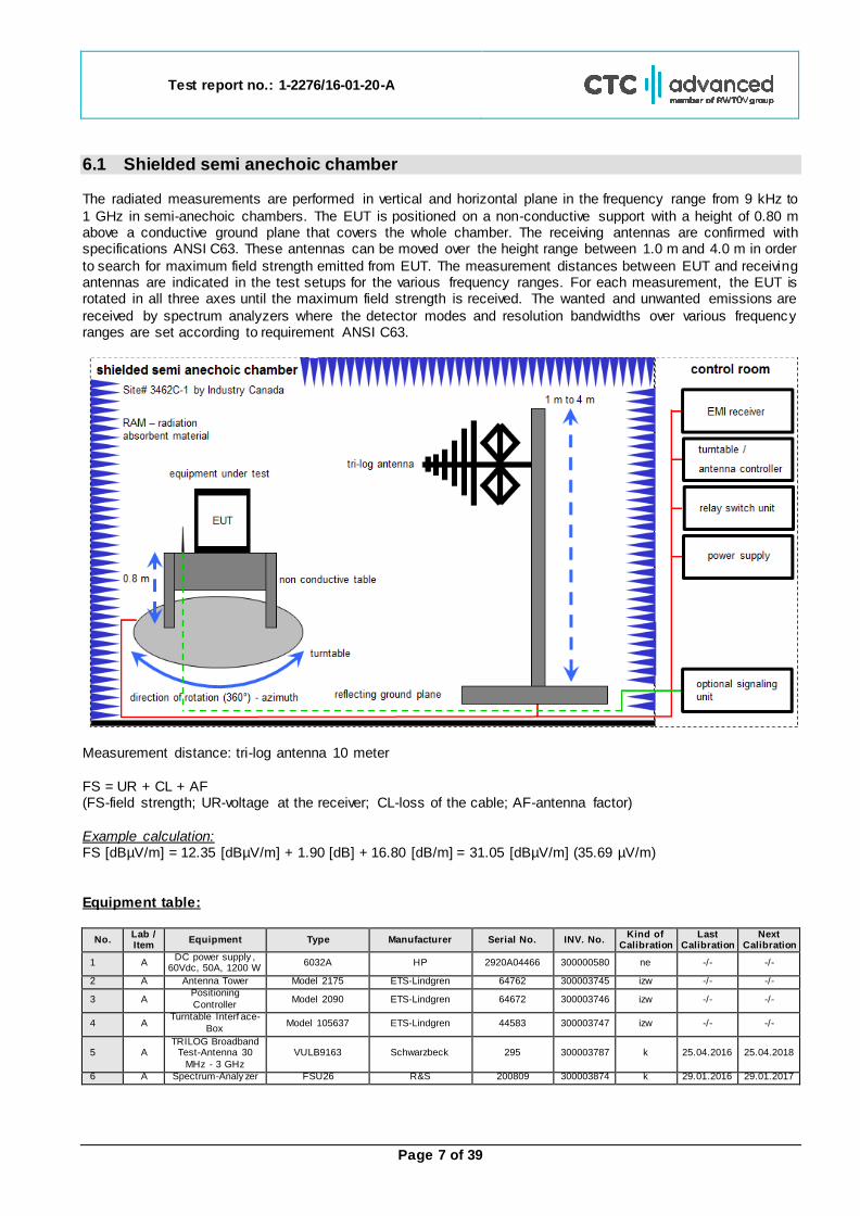
6.1 Shielded semi anechoic chamber The radiated measurements are performed in vertical and horizontal plane in the frequency range from 9 kHz to
1 GHz in semi-anechoic chambers. The EUT is positioned on a non-conductive support with a height of 0.80 m above a conductive ground plane that covers the whole chamber. The receiving antennas are confirmed with specifications ANSI C63. These antennas can be moved over the height range between 1.0 m and 4.0 m in order
to search for maximum field strength emitted from EUT. The measurement distances between EUT and receiving antennas are indicated in the test setups for the various frequency ranges. For each measurement, the EUT is rotated in all three axes until the maximum field strength is received. The wanted and unwanted emissions are
received by spectrum analyzers where the detector modes and resolution bandwidths over various frequency ranges are set according to requirement ANSI C63.
Measurement distance: tri-log antenna 10 meter
FS = UR + CL + AF (FS-field strength; UR-voltage at the receiver; CL-loss of the cable; AF-antenna factor)
Example calculation: FS [dBµV/m] = 12.35 [dBµV/m] + 1.90 [dB] + 16.80 [dB/m] = 31.05 [dBµV/m] (35.69 µV/m)
Equipment table:
No. Lab / Item
Equipment Type Manufacturer Serial No. INV. No. Kind of
Calibration Last
Calibration Next
Calibration
1 A DC power supply ,
60Vdc, 50A, 1200 W 6032A HP 2920A04466 300000580 ne -/- -/-
2 A Antenna Tower Model 2175 ETS-Lindgren 64762 300003745 izw -/- -/-
3 A Positioning
Controller Model 2090 ETS-Lindgren 64672 300003746 izw -/- -/-
4 A Turntable Interf ace-
Box Model 105637 ETS-Lindgren 44583 300003747 izw -/- -/-
5 A TRILOG Broadband
Test-Antenna 30
MHz - 3 GHz
VULB9163 Schwarzbeck 295 300003787 k 25.04.2016 25.04.2018
6 A Spectrum-Analy zer FSU26 R&S 200809 300003874 k 29.01.2016 29.01.2017
Test report no.: 1-2276/16-01-20-A
Page 8 of 39
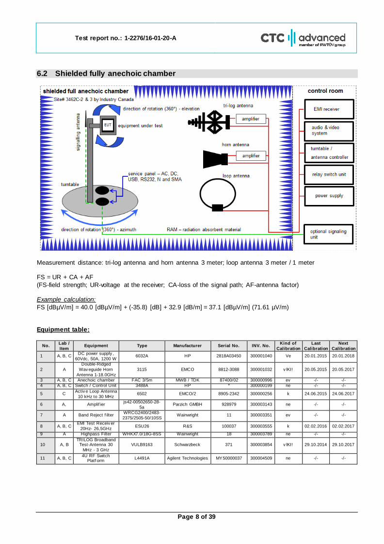
6.2 Shielded fully anechoic chamber
Measurement distance: tri-log antenna and horn antenna 3 meter; loop antenna 3 meter / 1 meter FS = UR + CA + AF
(FS-field strength; UR-voltage at the receiver; CA-loss of the signal path; AF-antenna factor) Example calculation:
FS [dBµV/m] = 40.0 [dBµV/m] + (-35.8) [dB] + 32.9 [dB/m] = 37.1 [dBµV/m] (71.61 µV/m)
Equipment table:
No. Lab /
Item Equipment Type Manufacturer Serial No. INV. No.
Kind of
Calibration
Last
Calibration
Next
Calibration
1 A, B, C DC power supply ,
60Vdc, 50A, 1200 W 6032A HP 2818A03450 300001040 Ve 20.01.2015 20.01.2018
2 A
Double-Ridged
Wav eguide Horn
Antenna 1-18.0GHz
3115 EMCO 8812-3088 300001032 v lKI! 20.05.2015 20.05.2017
3 A, B, C Anechoic chamber FAC 3/5m MWB / TDK 87400/02 300000996 ev -/- -/-
4 A, B, C Switch / Control Unit 3488A HP * 300000199 ne -/- -/-
5 C Activ e Loop Antenna
10 kHz to 30 MHz 6502 EMCO/2 8905-2342 300000256 k 24.06.2015 24.06.2017
6 A, Amplif ier js42-00502650-28-
5a Parzich GMBH 928979 300003143 ne -/- -/-
7 A Band Reject f ilter WRCG2400/2483-
2375/2505-50/10SS Wainwright 11 300003351 ev -/- -/-
8 A, B, C EMI Test Receiv er
20Hz- 26,5GHz ESU26 R&S 100037 300003555 k 02.02.2016 02.02.2017
9 A Highpass Filter WHKX7.0/18G-8SS Wainwright 18 300003789 ne -/- -/-
10 A, B TRILOG Broadband
Test-Antenna 30
MHz - 3 GHz
VULB9163 Schwarzbeck 371 300003854 v lKI! 29.10.2014 29.10.2017
11 A, B, C 4U RF Switch
Platf orm L4491A Agilent Technologies MY50000037 300004509 ne -/- -/-
Test report no.: 1-2276/16-01-20-A
Page 9 of 39
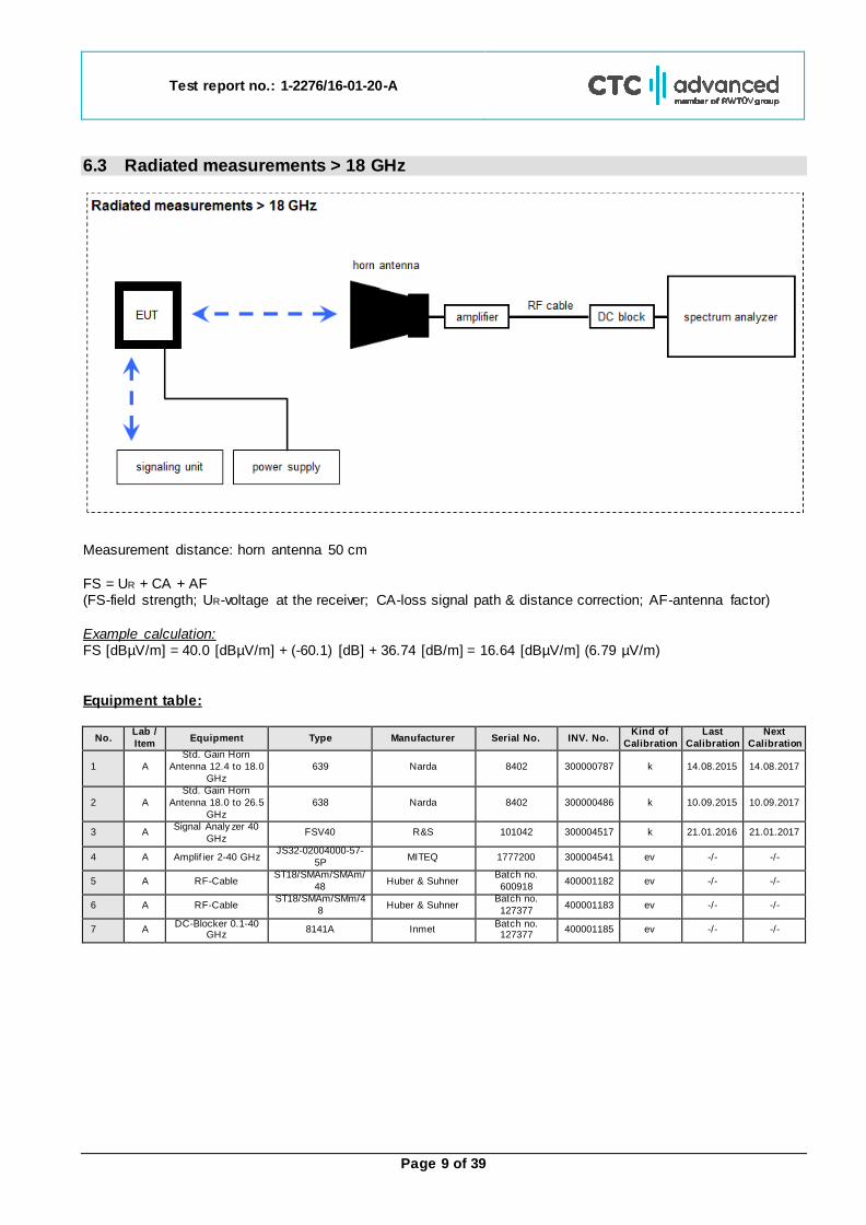
6.3 Radiated measurements > 18 GHz
Measurement distance: horn antenna 50 cm
FS = UR + CA + AF (FS-field strength; UR-voltage at the receiver; CA-loss signal path & distance correction; AF-antenna factor)
Example calculation: FS [dBµV/m] = 40.0 [dBµV/m] + (-60.1) [dB] + 36.74 [dB/m] = 16.64 [dBµV/m] (6.79 µV/m)
Equipment table:
No. Lab /
Item Equipment Type Manufacturer Serial No. INV. No.
Kind of
Calibration
Last
Calibration
Next
Calibration
1 A
Std. Gain Horn
Antenna 12.4 to 18.0
GHz
639 Narda 8402 300000787 k 14.08.2015 14.08.2017
2 A
Std. Gain Horn
Antenna 18.0 to 26.5
GHz
638 Narda 8402 300000486 k 10.09.2015 10.09.2017
3 A Signal Analy zer 40
GHz FSV40 R&S 101042 300004517 k 21.01.2016 21.01.2017
4 A Amplif ier 2-40 GHz JS32-02004000-57-
5P MITEQ 1777200 300004541 ev -/- -/-
5 A RF-Cable ST18/SMAm/SMAm/
48 Huber & Suhner
Batch no.
600918 400001182 ev -/- -/-
6 A RF-Cable ST18/SMAm/SMm/4
8 Huber & Suhner
Batch no.
127377 400001183 ev -/- -/-
7 A DC-Blocker 0.1-40
GHz 8141A Inmet
Batch no. 127377
400001185 ev -/- -/-
Test report no.: 1-2276/16-01-20-A
Page 10 of 39
7 Sequence of testing
7.1 Sequence of testing radiated spurious 9 kHz to 30 MHz Setup
The equipment is set up to simulate normal operation mode as described in the user manual or defined
by the manufacturer.
If the EUT is a tabletop system, a 2-axis positioner with 1.5 m height is used.
If the EUT is a floor standing device, it is placed directly on the turn table.
Auxiliary equipment and cables are positioned to simulate normal operation conditions as described in
ANSI C 63.4.
The AC power port of the EUT (if available) is connected to a power outlet below the turntable.
Measurement distance is 3 m (see ANSI C 63.4) – see test details.
EUT is set into operation.
Premeasurement
The turntable rotates from 0° to 315° using 45° steps.
The antenna height is 1.5 m.
At each turntable position the analyzer sweeps with positive-peak detector to find the maximum of all emissions.
Final measurement
Identified emissions during the premeasurement are maximized by the software by rotating the turntable from 0° to 360°. In case of the 2-axis positioner is used the elevation axis is also rotated from 0° to 360°.
The final measurement is done in the position (turntable and elevation) causing the highest emissions with quasi-peak (as described in ANSI C 63.4).
Final levels, frequency, measuring time, bandwidth, turntable position, correction factor, margin to the limit and limit will be recorded. A plot with the graph of the premeasurement and the limit is stored.
Test report no.: 1-2276/16-01-20-A
Page 11 of 39
7.2 Sequence of testing radiated spurious 30 MHz to 1 GHz Setup
The equipment is set up to simulate normal operation mode as described in the user manual or defined by the manufacturer.
If the EUT is a tabletop system, a table with 0.8 m height is used, which is placed on the ground plane.
If the EUT is a floor standing device, it is placed on the ground plane with insulation between both.
Auxiliary equipment and cables are positioned to simulate normal operation conditions as described in ANSI C 63.4.
The AC power port of the EUT (if available) is connected to a power outlet below the turntable.
Measurement distance is 10 m or 3 m (see ANSI C 63.4) – see test details.
EUT is set into operation. Premeasurement
The turntable rotates from 0° to 315° using 45° steps.
The antenna is polarized vertical and horizontal.
The antenna height changes from 1 m to 3 m.
At each turntable position, antenna polarization and height the analyzer sweeps three times in peak to find the maximum of all emissions.
Final measurement
The final measurement is performed for at least six highest peaks according to the requirements of the
ANSI C63.4.
Based on antenna and turntable positions at which the peak values are measured the software maximize the peaks by changing turntable position ± 45° and antenna height between 1 and 4 m.
The final measurement is done with quasi-peak detector (as described in ANSI C 63.4).
Final levels, frequency, measuring time, bandwidth, antenna height, antenna polarization, turntable angle, correction factor, margin to the limit and limit are recorded. A plot with the graph of the premeasurement with marked maximum final results and the limit is stored.
Test report no.: 1-2276/16-01-20-A
Page 12 of 39
7.3 Sequence of testing radiated spurious 1 GHz to 18 GHz Setup
The equipment is set up to simulate normal operation mode as described in the user manual or defined by the manufacturer.
If the EUT is a tabletop system, a 2-axis positioner with 1.5 m height is used.
If the EUT is a floor standing device, it is placed directly on the turn table.
Auxiliary equipment and cables are positioned to simulate normal operation conditions as described in ANSI C 63.4.
The AC power port of the EUT (if available) is connected to a power outlet below the turntable.
Measurement distance is 3 m (see ANSI C 63.4) – see test details.
EUT is set into operation. Premeasurement
The turntable rotates from 0° to 315° using 45° steps.
The antenna is polarized vertical and horizontal.
The antenna height is 1.5 m.
At each turntable position and antenna polarization the analyzer sweeps with positive peak detector to find the maximum of all emissions.
Final measurement
The final measurement is performed for at least six highest peaks according to the requirements of the
ANSI C63.4.
Based on antenna and turntable positions at which the peak values are measured the software maximizes the peaks by rotating the turntable from 0° to 360°. This measurement is repeated for different EUT-table
positions (0° to 150° in 30°-steps) and for both antenna polarizations.
The final measurement is done in the position (turntable, EUT-table and antenna polarization) causing the highest emissions with Peak and RMS detector (as described in ANSI C 63.4).
Final levels, frequency, measuring time, bandwidth, turntable position, EUT-table position, antenna
polarization, correction factor, margin to the limit and limit are recorded. A plot with the graph of the premeasurement with marked maximum final results and the limit is stored.
Test report no.: 1-2276/16-01-20-A
Page 13 of 39
7.4 Sequence of testing radiated spurious above 18 GHz Setup
The equipment is set up to simulate normal operation mode as described in the user manual or defined by the manufacturer.
Auxiliary equipment and cables are positioned to simulate normal operation conditions as described in ANSI C 63.4.
The AC power port of the EUT (if available) is connected to a power outlet.
The measurement distance is as appropriate (e.g. 0.5 m).
The EUT is set into operation.
Premeasurement
The test antenna is handheld and moved carefully over the EUT to cover the EUT’s whole sphere and different polarizations of the antenna.
Final measurement
The final measurement is performed at the position and antenna orientation causing the highest emissions
with Peak and RMS detector (as described in ANSI C 63.4).
Final levels, frequency, measuring time, bandwidth, correction factor, margin to the limit and limit are recorded. A plot with the graph of the premeasurement and the limit is stored.
Test report no.: 1-2276/16-01-20-A
Page 14 of 39
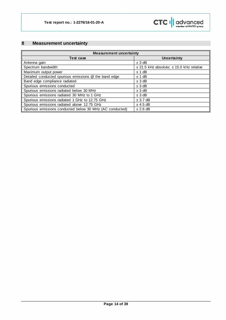
8 Measurement uncertainty
Measurement uncertainty
Test case Uncertainty
Antenna gain ± 3 dB
Spectrum bandwidth ± 21.5 kHz absolute; ± 15.0 kHz relative
Maximum output power ± 1 dB
Detailed conducted spurious emissions @ the band edge ± 1 dB
Band edge compliance radiated ± 3 dB
Spurious emissions conducted ± 3 dB
Spurious emissions radiated below 30 MHz ± 3 dB
Spurious emissions radiated 30 MHz to 1 GHz ± 3 dB
Spurious emissions radiated 1 GHz to 12.75 GHz ± 3.7 dB
Spurious emissions radiated above 12.75 GHz ± 4.5 dB
Spurious emissions conducted below 30 MHz (AC conducted) ± 2.6 dB
Test report no.: 1-2276/16-01-20-A
Page 15 of 39
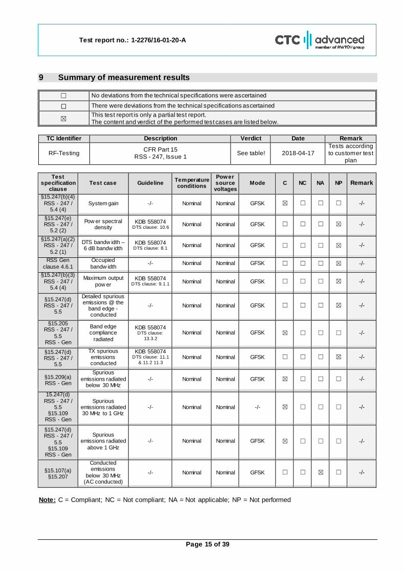
9 Summary of measurement results
☐ No deviations from the technical specifications were ascertained
☐ There were deviations from the technical specifications ascertained
☒ This test report is only a partial test report. The content and verdict of the performed test cases are listed below.
TC Identifier Description Verdict Date Remark
RF-Testing CFR Part 15
RSS - 247, Issue 1 See table! 2018-04-17
Tests according to customer test
plan
Test
specification clause
Test case Guideline Temperature conditions
Power source voltages
Mode C NC NA NP Remark
§15.247(b)(4)
RSS - 247 / 5.4 (4)
System gain -/- Nominal Nominal GFSK ☒ ☐ ☐ ☐ -/-
§15.247(e) RSS - 247 /
5.2 (2)
Pow er spectral density
KDB 558074 DTS clause: 10.6 Nominal Nominal GFSK ☐ ☐ ☐ ☒ -/-
§15.247(a)(2) RSS - 247 /
5.2 (1)
DTS bandw idth – 6 dB bandw idth
KDB 558074 DTS clause: 8.1 Nominal Nominal GFSK ☐ ☐ ☐ ☒ -/-
RSS Gen
clause 4.6.1
Occupied
bandw idth -/- Nominal Nominal GFSK ☐ ☐ ☐ ☒ -/-
§15.247(b)(3)
RSS - 247 / 5.4 (4)
Maximum output
pow er KDB 558074
DTS clause: 9.1.1 Nominal Nominal GFSK ☐ ☐ ☐ ☒ -/-
§15.247(d) RSS - 247 /
5.5
Detailed spurious emissions @ the
band edge - conducted
-/- Nominal Nominal GFSK ☐ ☐ ☐ ☒ -/-
§15.205 RSS - 247 /
5.5 RSS - Gen
Band edge compliance
radiated
KDB 558074 DTS clause:
13.3.2 Nominal Nominal GFSK ☒ ☐ ☐ ☐ -/-
§15.247(d) RSS - 247 /
5.5
TX spurious emissions conducted
KDB 558074 DTS clause: 11.1
& 11.2 11.3 Nominal Nominal GFSK ☐ ☐ ☐ ☒ -/-
§15.209(a) RSS - Gen
Spurious
emissions radiated below 30 MHz
-/- Nominal Nominal GFSK ☒ ☐ ☐ ☐ -/-
15.247(d)
RSS - 247 / 5.5
§15.109 RSS - Gen
Spurious emissions radiated 30 MHz to 1 GHz
-/- Nominal Nominal -/- ☒ ☐ ☐ ☐ -/-
§15.247(d) RSS - 247 /
5.5 §15.109
RSS - Gen
Spurious emissions radiated
above 1 GHz
-/- Nominal Nominal GFSK ☒ ☐ ☐ ☐ -/-
§15.107(a) §15.207
Conducted emissions
below 30 MHz (AC conducted)
-/- Nominal Nominal GFSK ☐ ☐ ☒ ☐ -/-
Note: C = Compliant; NC = Not compliant; NA = Not applicable; NP = Not performed
Test report no.: 1-2276/16-01-20-A
Page 16 of 39
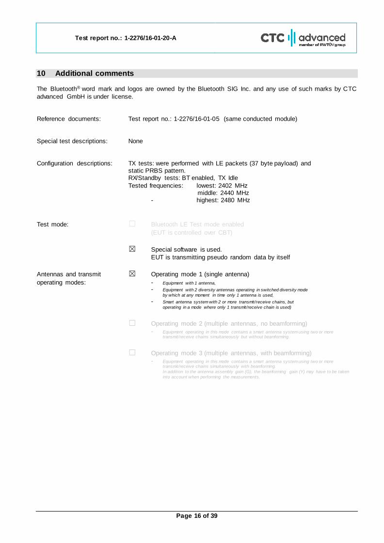
10 Additional comments The Bluetooth® word mark and logos are owned by the Bluetooth SIG Inc. and any use of such marks by CTC
advanced GmbH is under license.
Reference documents: Test report no.: 1-2276/16-01-05 (same conducted module)
Special test descriptions: None
Configuration descriptions: TX tests: were performed with LE packets (37 byte payload) and static PRBS pattern. RX/Standby tests: BT enabled, TX Idle
Tested frequencies: lowest: 2402 MHz middle: 2440 MHz
- highest: 2480 MHz
Test mode: ☐ Bluetooth LE Test mode enabled
(EUT is controlled over CBT)
☒ Special software is used.
EUT is transmitting pseudo random data by itself
Antennas and transmit ☒ Operating mode 1 (single antenna)
operating modes: - Equipment with 1 antenna,
- Equipment with 2 diversity antennas operating in switched diversity mode
by which at any moment in time only 1 antenna is used,
- Smart antenna system with 2 or more transmit/receive chains, but
operating in a mode where only 1 transmit/receive chain is used)
☐ Operating mode 2 (multiple antennas, no beamforming)
- Equipment operating in this mode contains a smart antenna system using two or more transmit/receive chains simultaneously but without beamforming.
☐ Operating mode 3 (multiple antennas, with beamforming)
- Equipment operating in this mode contains a smart antenna system using two or more transmit/receive chains simultaneously with beamforming.
In addition to the antenna assembly gain (G), the beamforming gain (Y) may have to be taken
into account when performing the measurements.
Test report no.: 1-2276/16-01-20-A
Page 17 of 39
11 Measurement results
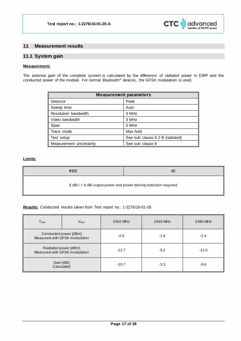
11.1 System gain Measurement:
The antenna gain of the complete system is calculated by the difference of radiated power in EIRP and the conducted power of the module. For normal Bluetooth® devices, the GFSK modulation is used.
Measurement parameters
Detector Peak
Sweep time Auto
Resolution bandwidth 3 MHz
Video bandwidth 3 MHz
Span 5 MHz
Trace mode Max hold
Test setup See sub clause 6.2 B (radiated)
Measurement uncertainty See sub clause 8
Limits:
FCC IC
6 dBi / > 6 dBi output power and power density reduction required
Results: Conducted results taken from Test report no.: 1-2276/16-01-05
Tnom Vnom 2402 MHz 2440 MHz 2480 MHz
Conducted power [dBm] Measured with GFSK modulation
-2.0 -1.9 -2.4
Radiated power [dBm] Measured with GFSK modulation
-12.7 -5.2 -12.0
Gain [dBi] Calculated
-10.7 -3.3 -9.6
Test report no.: 1-2276/16-01-20-A
Page 18 of 39
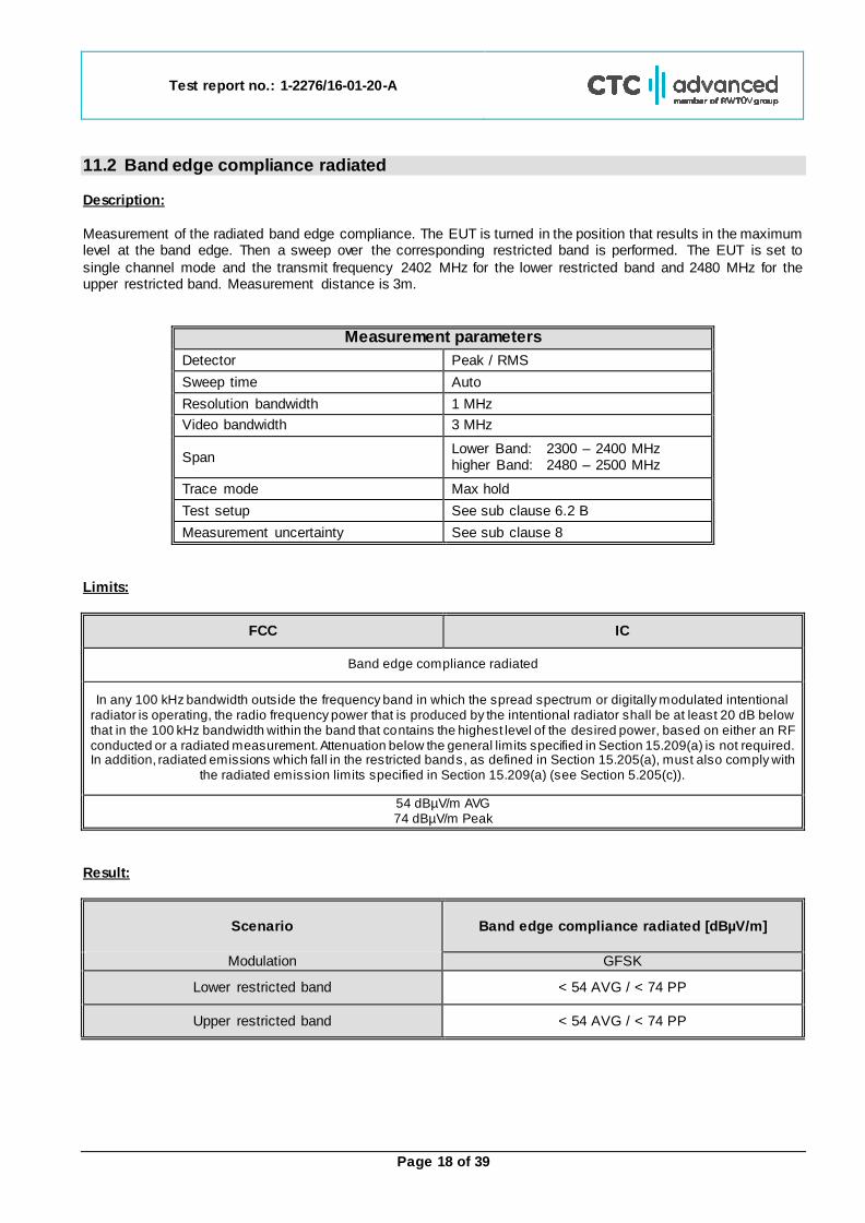
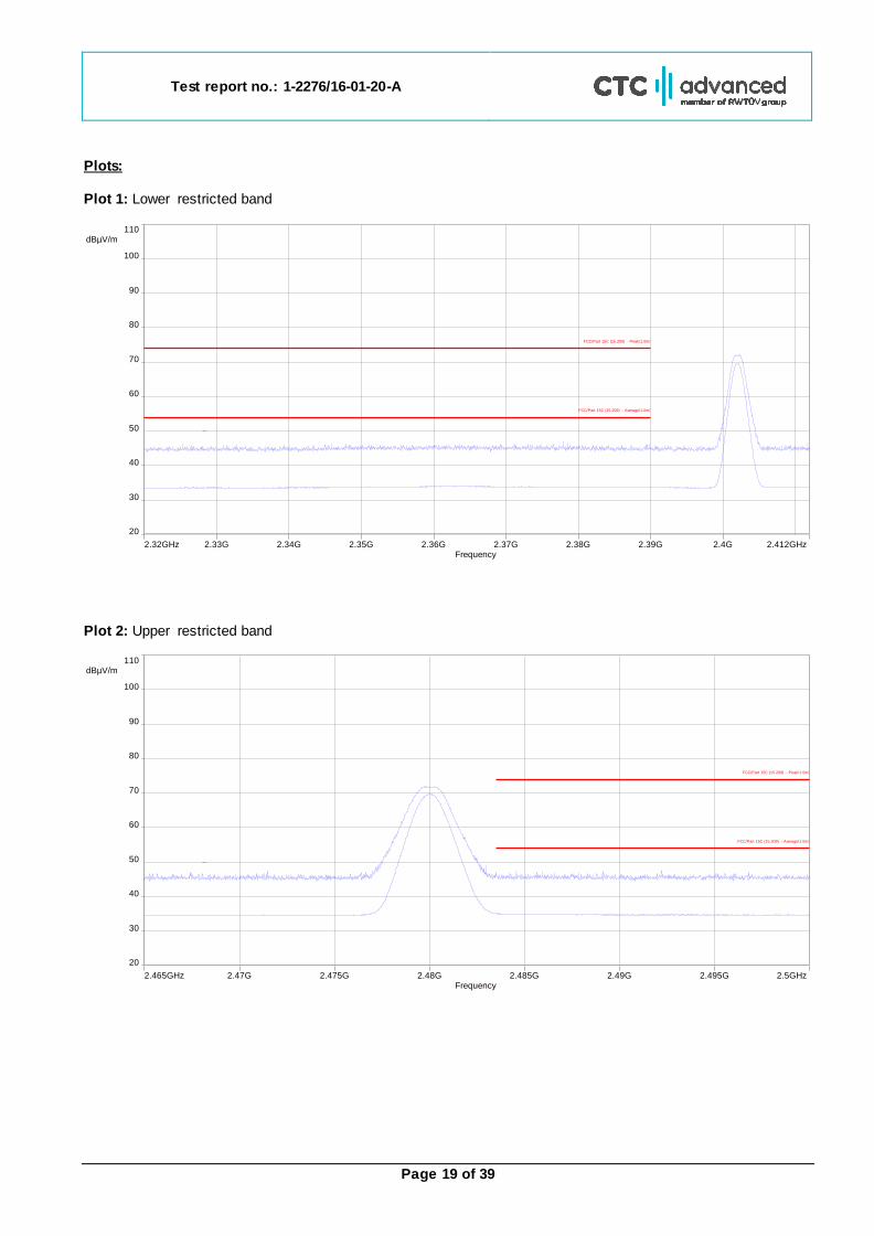
11.2 Band edge compliance radiated Description:
Measurement of the radiated band edge compliance. The EUT is turned in the position that results in the maximum level at the band edge. Then a sweep over the corresponding restricted band is performed. The EUT is set to
single channel mode and the transmit frequency 2402 MHz for the lower restricted band and 2480 MHz for the upper restricted band. Measurement distance is 3m.
Measurement parameters
Detector Peak / RMS
Sweep time Auto
Resolution bandwidth 1 MHz
Video bandwidth 3 MHz
Span Lower Band: 2300 – 2400 MHz higher Band: 2480 – 2500 MHz
Trace mode Max hold
Test setup See sub clause 6.2 B
Measurement uncertainty See sub clause 8
Limits:
FCC IC
Band edge compliance radiated
In any 100 kHz bandwidth outside the frequency band in which the spread spectrum or digitally modulated intentional radiator is operating, the radio frequency power that is produced by the intentional radiator shall be at least 20 dB below that in the 100 kHz bandwidth within the band that contains the highest level of the desired power, based on either an RF conducted or a radiated measurement. Attenuation below the general limits specified in Section 15.209(a) is not required. In addition, radiated emissions which fall in the restricted bands, as defined in Section 15.205(a), must also comply with
the radiated emission limits specified in Section 15.209(a) (see Section 5.205(c)).
54 dBµV/m AVG 74 dBµV/m Peak
Result:
Scenario Band edge compliance radiated [dBµV/m]
Modulation GFSK
Lower restricted band < 54 AVG / < 74 PP
Upper restricted band < 54 AVG / < 74 PP
Test report no.: 1-2276/16-01-20-A
Page 19 of 39
Plots: Plot 1: Lower restricted band
Plot 2: Upper restricted band
2.32GHz 2.412GHz2.4G2.37G2.34G 2.39G2.36G2.33G 2.38G2.35GFrequency
20
110 dBµV/m
100
70
40
90
60
30
80
50
FCC/Part 15C (15.209) - Peak/1.0m/
FCC/Part 15C (15.209) - Average/1.0m/
2.465GHz 2.5GHz2.49G2.475G 2.485G2.47G 2.495G2.48GFrequency
20
110 dBµV/m
100
70
40
90
60
30
80
50
FCC/Part 15C (15.209) - Peak/1.0m/
FCC/Part 15C (15.209) - Average/1.0m/
Test report no.: 1-2276/16-01-20-A
Page 20 of 39
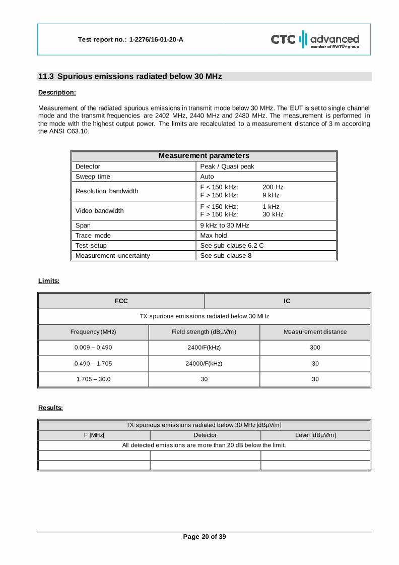
11.3 Spurious emissions radiated below 30 MHz Description:
Measurement of the radiated spurious emissions in transmit mode below 30 MHz. The EUT is set to single channel mode and the transmit frequencies are 2402 MHz, 2440 MHz and 2480 MHz. The measurement is performed in
the mode with the highest output power. The limits are recalculated to a measurement distance of 3 m according the ANSI C63.10.
Measurement parameters
Detector Peak / Quasi peak
Sweep time Auto
Resolution bandwidth F < 150 kHz: 200 Hz
F > 150 kHz: 9 kHz
Video bandwidth F < 150 kHz: 1 kHz F > 150 kHz: 30 kHz
Span 9 kHz to 30 MHz
Trace mode Max hold
Test setup See sub clause 6.2 C
Measurement uncertainty See sub clause 8
Limits:
FCC IC
TX spurious emissions radiated below 30 MHz
Frequency (MHz) Field strength (dBµV/m) Measurement distance
0.009 – 0.490 2400/F(kHz) 300
0.490 – 1.705 24000/F(kHz) 30
1.705 – 30.0 30 30
Results:
TX spurious emissions radiated below 30 MHz [dBµV/m]
F [MHz] Detector Level [dBµV/m]
All detected emissions are more than 20 dB below the limit.
Test report no.: 1-2276/16-01-20-A
Page 21 of 39
Plots: Plot 1: 9 kHz to 30 MHz, 2402 MHz, transmit mode
Plot 2: 9 kHz to 30 MHz, 2440 MHz, transmit mode
9kHz 30MHz10M1M100kFrequency
10
130 dBµV/m
120
90
60
30
110
80
50
20
100
70
40
FCC/Part 15C (15.209) - Peak/3.0m/
FCC/Part 15C (15.209) - QPeak/3.0m/
FCC/Part 15C (15.209) - Average/3.0m/
9kHz 30MHz10M1M100kFrequency
10
130 dBµV/m
120
90
60
30
110
80
50
20
100
70
40
FCC/Part 15C (15.209) - Peak/3.0m/
FCC/Part 15C (15.209) - QPeak/3.0m/
FCC/Part 15C (15.209) - Average/3.0m/

Test report no.: 1-2276/16-01-20-A
Page 22 of 39
Plot 3: 9 kHz to 30 MHz, 2480 MHz, transmit mode
9kHz 30MHz10M1M100kFrequency
10
130 dBµV/m
120
90
60
30
110
80
50
20
100
70
40
FCC/Part 15C (15.209) - Peak/3.0m/
FCC/Part 15C (15.209) - QPeak/3.0m/
FCC/Part 15C (15.209) - Average/3.0m/

Test report no.: 1-2276/16-01-20-A
Page 23 of 39
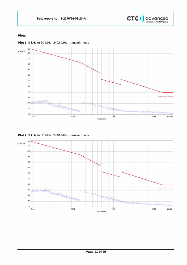
11.4 Spurious emissions radiated 30 MHz to 1 GHz Description:
Measurement of the radiated spurious emissions in transmit mode. The EUT is set to single channel mode and the transmit frequencies are 2402 MHz, 2440 MHz and 2480 MHz. The measurement is performed in the mode
with the highest output power.
Measurement parameters
Detector Peak / Quasi Peak
Sweep time Auto
Resolution bandwidth 120 kHz
Video bandwidth 3 x RBW
Span 30 MHz to 1 GHz
Trace mode Max hold
Measured modulation GFSK
Test setup See sub clause 6.1 A
Measurement uncertainty See sub clause 8
The modulation with the highest output power was used to perform the transmitter spurious emissions. If spurious
were detected a re-measurement was performed on the detected frequency with each modulation.
Limits:
FCC IC
TX spurious emissions radiated
In any 100 kHz bandwidth outside the frequency band in which the spread spectrum or digitally modulated intentional radiator is operating, the radio frequency power that is produced by the intentional radiator shall be at least 20 dB below that in the 100 kHz bandwidth within the band that contains the highest level of the desired power, based on either an RF conducted or a radiated measurement. Attenuation below the general limits specified in Section 15.209(a) is not required. In addition, radiated emissions which fall in the restricted bands, as defined in §15.205(a), must also comply with the radiated emission limits specified in §15.209(a) (see §15.205(c)).
§15.209
Frequency (MHz) Field strength (dBµV/m) Measurement distance
30 - 88 30.0 10
88 – 216 33.5 10
216 – 960 36.0 10
Above 960 54.0 3
Test report no.: 1-2276/16-01-20-A
Page 24 of 39
Plots: Transmit mode Plot 1: 30 MHz to 1 GHz, TX mode, 2402 MHz, vertical & horizontal polarization
Final results:
Frequency (MHz)
QuasiPeak (dBµV/m)
Limit (dBµV/m)
Margin (dB)
Meas. Time (ms)
Bandwidth (kHz)
Height (cm)
Pol Azimuth
(deg) Corr. (dB)
575.665500 17.19 36.00 18.81 1000.0 120.000 180.0 H 207.0 20.1
607.999950 19.26 36.00 16.74 1000.0 120.000 101.0 H 219.0 20.8
720.024450 20.22 36.00 15.78 1000.0 120.000 101.0 H 103.0 22.0
912.618300 21.63 36.00 14.37 1000.0 120.000 185.0 H 83.0 24.2
928.476450 21.71 36.00 14.29 1000.0 120.000 179.0 H 83.0 24.3
943.996200 33.15 36.00 2.85 1000.0 120.000 98.0 H 243.0 24.3
960.126150 21.90 44.00 22.10 1000.0 120.000 178.0 H 193.0 24.5
0
1 0
2 0
3 0
4 0
5 0
6 0
7 0
8 0
3 0 M 5 0 6 0 8 0 1 0 0 M 2 0 0 3 0 0 4 0 0 5 0 0 8 0 0 1 ,0 5 G
Level in
dB
µV
/m
F re q u e n c y in H z
FCC _ 1 0 m_ B
Test report no.: 1-2276/16-01-20-A
Page 25 of 39
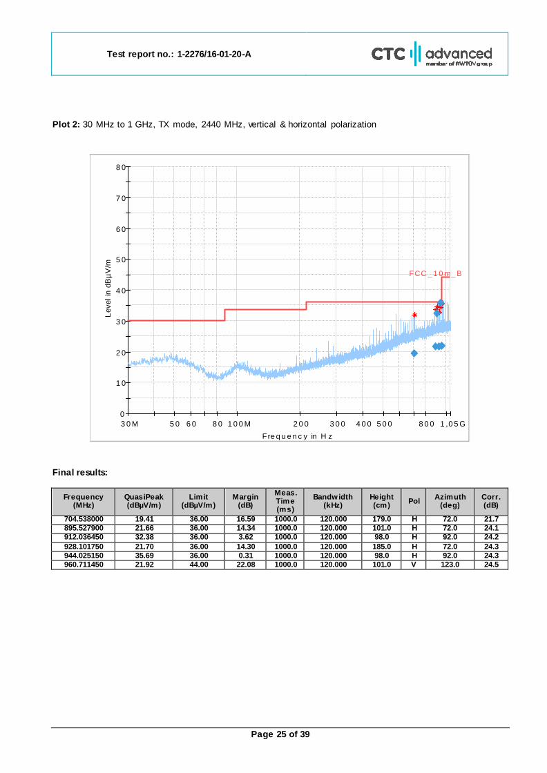
Plot 2: 30 MHz to 1 GHz, TX mode, 2440 MHz, vertical & horizontal polarization
Final results:
Frequency (MHz)
QuasiPeak (dBµV/m)
Limit (dBµV/m)
Margin (dB)
Meas. Time (ms)
Bandwidth (kHz)
Height (cm)
Pol Azimuth
(deg) Corr. (dB)
704.538000 19.41 36.00 16.59 1000.0 120.000 179.0 H 72.0 21.7
895.527900 21.66 36.00 14.34 1000.0 120.000 101.0 H 72.0 24.1
912.036450 32.38 36.00 3.62 1000.0 120.000 98.0 H 92.0 24.2
928.101750 21.70 36.00 14.30 1000.0 120.000 185.0 H 72.0 24.3
944.025150 35.69 36.00 0.31 1000.0 120.000 98.0 H 92.0 24.3
960.711450 21.92 44.00 22.08 1000.0 120.000 101.0 V 123.0 24.5
0
1 0
2 0
3 0
4 0
5 0
6 0
7 0
8 0
3 0 M 5 0 6 0 8 0 1 0 0 M 2 0 0 3 0 0 4 0 0 5 0 0 8 0 0 1 ,0 5 G
Level in
dB
µV
/m
F re q u e n c y in H z
FCC _ 1 0 m_ B
Test report no.: 1-2276/16-01-20-A
Page 26 of 39
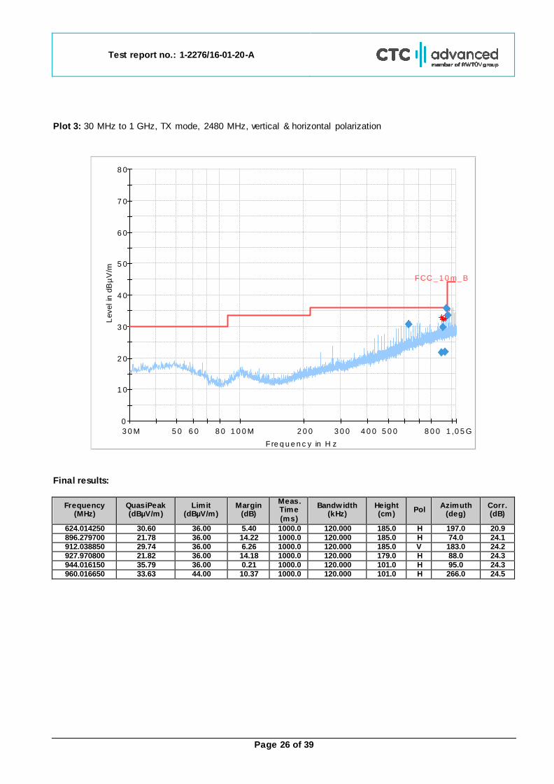
Plot 3: 30 MHz to 1 GHz, TX mode, 2480 MHz, vertical & horizontal polarization
Final results:
Frequency (MHz)
QuasiPeak (dBµV/m)
Limit (dBµV/m)
Margin (dB)
Meas. Time
(ms)
Bandwidth (kHz)
Height (cm)
Pol Azimuth
(deg) Corr. (dB)
624.014250 30.60 36.00 5.40 1000.0 120.000 185.0 H 197.0 20.9
896.279700 21.78 36.00 14.22 1000.0 120.000 185.0 H 74.0 24.1
912.038850 29.74 36.00 6.26 1000.0 120.000 185.0 V 183.0 24.2
927.970800 21.82 36.00 14.18 1000.0 120.000 179.0 H 88.0 24.3
944.016150 35.79 36.00 0.21 1000.0 120.000 101.0 H 95.0 24.3
960.016650 33.63 44.00 10.37 1000.0 120.000 101.0 H 266.0 24.5
0
1 0
2 0
3 0
4 0
5 0
6 0
7 0
8 0
3 0 M 5 0 6 0 8 0 1 0 0 M 2 0 0 3 0 0 4 0 0 5 0 0 8 0 0 1 ,0 5 G
Level in
dB
µV
/m
F re q u e n c y in H z
FCC _ 1 0 m_ B
Test report no.: 1-2276/16-01-20-A
Page 27 of 39
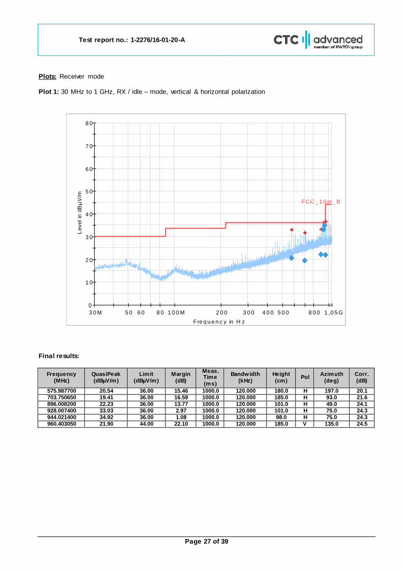
Plots: Receiver mode Plot 1: 30 MHz to 1 GHz, RX / idle – mode, vertical & horizontal polarization
Final results:
Frequency
(MHz)
QuasiPeak
(dBµV/m)
Limit
(dBµV/m)
Margin
(dB)
Meas. Time
(ms)
Bandwidth
(kHz)
Height
(cm) Pol
Azimuth
(deg)
Corr.
(dB)
575.987700 20.54 36.00 15.46 1000.0 120.000 180.0 H 197.0 20.1
703.750650 19.41 36.00 16.59 1000.0 120.000 185.0 H 93.0 21.6
896.008200 22.23 36.00 13.77 1000.0 120.000 101.0 H 49.0 24.1
928.007400 33.03 36.00 2.97 1000.0 120.000 101.0 H 75.0 24.3
944.021400 34.92 36.00 1.08 1000.0 120.000 98.0 H 75.0 24.3
960.403050 21.90 44.00 22.10 1000.0 120.000 185.0 V 135.0 24.5
0
1 0
2 0
3 0
4 0
5 0
6 0
7 0
8 0
3 0 M 5 0 6 0 8 0 1 0 0 M 2 0 0 3 0 0 4 0 0 5 0 0 8 0 0 1 ,0 5 G
Level in
dB
µV
/m
F re q u e n c y in H z
FCC _ 1 0 m_ B
Test report no.: 1-2276/16-01-20-A
Page 28 of 39
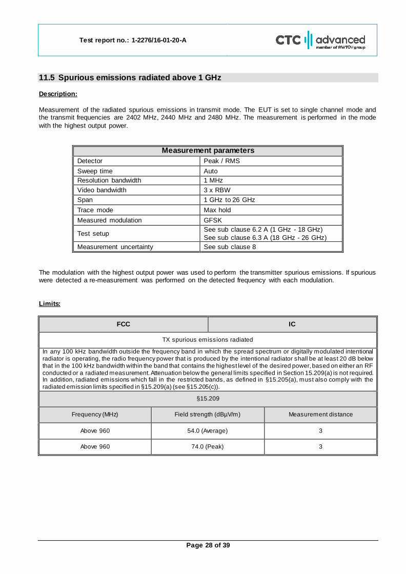
11.5 Spurious emissions radiated above 1 GHz Description:
Measurement of the radiated spurious emissions in transmit mode. The EUT is set to single channel mode and the transmit frequencies are 2402 MHz, 2440 MHz and 2480 MHz. The measurement is performed in the mode
with the highest output power.
Measurement parameters
Detector Peak / RMS
Sweep time Auto
Resolution bandwidth 1 MHz
Video bandwidth 3 x RBW
Span 1 GHz to 26 GHz
Trace mode Max hold
Measured modulation GFSK
Test setup See sub clause 6.2 A (1 GHz - 18 GHz)
See sub clause 6.3 A (18 GHz - 26 GHz) Measurement uncertainty See sub clause 8
The modulation with the highest output power was used to perform the transmitter spurious emissions. If spurious were detected a re-measurement was performed on the detected frequency with each modulation.
Limits:
FCC IC
TX spurious emissions radiated
In any 100 kHz bandwidth outside the frequency band in which the spread spectrum or digitally modulated intentional radiator is operating, the radio frequency power that is produced by the intentional radiator shall be at least 20 dB below that in the 100 kHz bandwidth within the band that contains the highest level of the desired power, based on either an RF conducted or a radiated measurement. Attenuation below the general limits specified in Section 15.209(a) is not required. In addition, radiated emissions which fall in the restricted bands, as defined in §15.205(a), must also comply with the radiated emission limits specified in §15.209(a) (see §15.205(c)).
§15.209
Frequency (MHz) Field strength (dBµV/m) Measurement distance
Above 960 54.0 (Average) 3
Above 960 74.0 (Peak) 3
Test report no.: 1-2276/16-01-20-A
Page 29 of 39
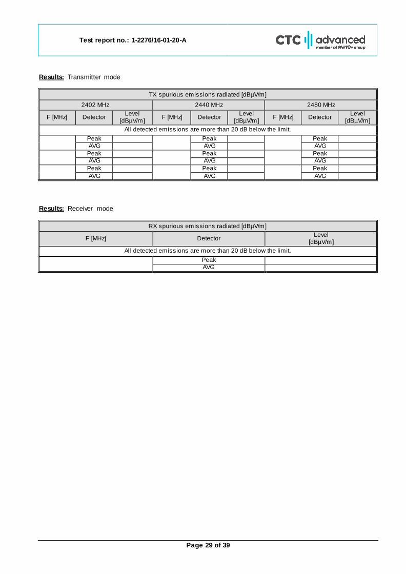
Results: Transmitter mode
TX spurious emissions radiated [dBµV/m]
2402 MHz 2440 MHz 2480 MHz
F [MHz] Detector Level
[dBµV/m] F [MHz] Detector
Level [dBµV/m]
F [MHz] Detector Level
[dBµV/m]
All detected emissions are more than 20 dB below the limit.
Peak
Peak
Peak
AVG AVG AVG
Peak
Peak
Peak
AVG AVG AVG
Peak
Peak
Peak
AVG AVG AVG
Results: Receiver mode
RX spurious emissions radiated [dBµV/m]
F [MHz] Detector Level
[dBµV/m]
All detected emissions are more than 20 dB below the limit.
Peak AVG
Test report no.: 1-2276/16-01-20-A
Page 30 of 39
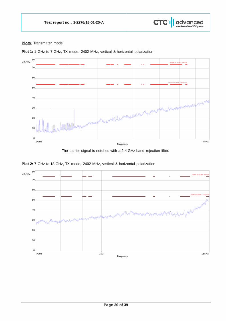
Plots: Transmitter mode Plot 1: 1 GHz to 7 GHz, TX mode, 2402 MHz, vertical & horizontal polarization
The carrier signal is notched with a 2.4 GHz band rejection filter.
Plot 2: 7 GHz to 18 GHz, TX mode, 2402 MHz, vertical & horizontal polarization
1GHz 7GHzFrequency
0
80 dBµV/m
50
20
70
40
10
60
30
FCC/Part 15C (15.209) - Peak/3.0m/
FCC/Part 15C (15.209) - QPeak/3.0m/
FCC/Part 15C (15.209) - Average/3.0m/
7GHz 18GHz10GFrequency
0
80 dBµV/m
50
20
70
40
10
60
30
FCC/Part 15C (15.209) - Peak/1.0m/
FCC/Part 15C (15.209) - Average/1.0m/
Test report no.: 1-2276/16-01-20-A
Page 31 of 39
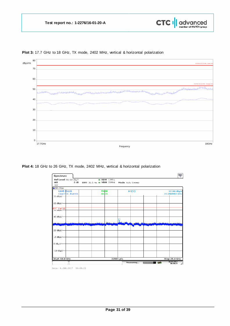
Plot 3: 17.7 GHz to 18 GHz, TX mode, 2402 MHz, vertical & horizontal polarization
Plot 4: 18 GHz to 26 GHz, TX mode, 2402 MHz, vertical & horizontal polarization
17.7GHz 18GHzFrequency
0
80 dBµV/m
50
20
70
40
10
60
30
FCC/Part 15C (15.209) - Peak/1.0m/
FCC/Part 15C (15.209) - Average/1.0m/
Date: 6.JAN.2017 06:48:23
Test report no.: 1-2276/16-01-20-A
Page 32 of 39
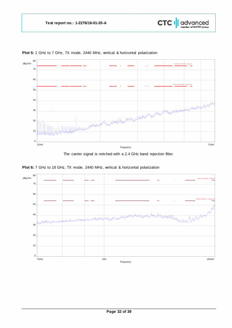
Plot 5: 1 GHz to 7 GHz, TX mode, 2440 MHz, vertical & horizontal polarization
The carrier signal is notched with a 2.4 GHz band rejection filter.
Plot 6: 7 GHz to 18 GHz, TX mode, 2440 MHz, vertical & horizontal polarization
1GHz 7GHzFrequency
0
80 dBµV/m
50
20
70
40
10
60
30
FCC/Part 15C (15.209) - Peak/3.0m/
FCC/Part 15C (15.209) - QPeak/3.0m/
FCC/Part 15C (15.209) - Average/3.0m/
7GHz 18GHz10GFrequency
0
80 dBµV/m
50
20
70
40
10
60
30
FCC/Part 15C (15.209) - Peak/1.0m/
FCC/Part 15C (15.209) - Average/1.0m/

Test report no.: 1-2276/16-01-20-A
Page 33 of 39
Plot 7: 17.7 GHz to 18 GHz, TX mode, 2440 MHz, vertical & horizontal polarization
Plot 8: 18 GHz to 26 GHz, TX mode, 2440 MHz, vertical & horizontal polarization
17.7GHz 18GHzFrequency
0
80 dBµV/m
50
20
70
40
10
60
30
FCC/Part 15C (15.209) - Peak/1.0m/
FCC/Part 15C (15.209) - Average/1.0m/
Date: 6.JAN.2017 06:46:34
Test report no.: 1-2276/16-01-20-A
Page 34 of 39
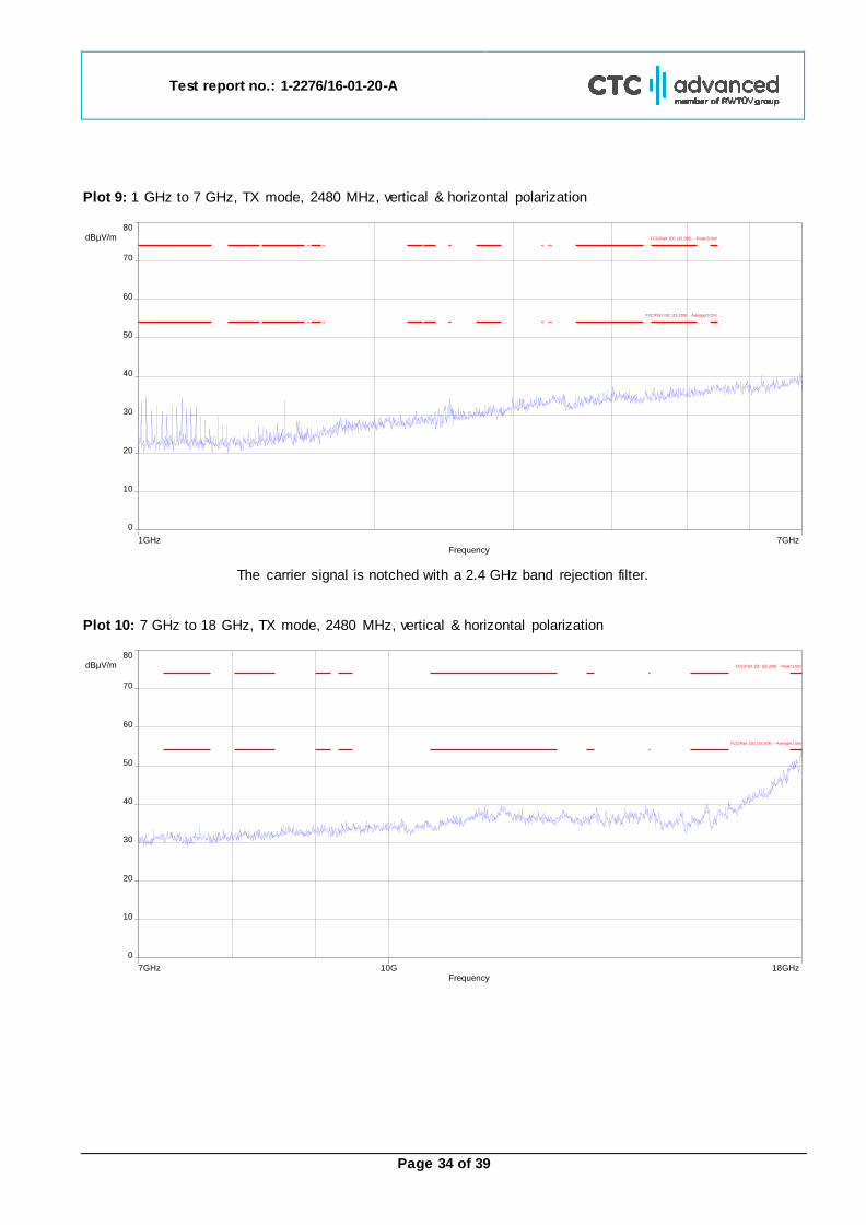
Plot 9: 1 GHz to 7 GHz, TX mode, 2480 MHz, vertical & horizontal polarization
The carrier signal is notched with a 2.4 GHz band rejection filter.
Plot 10: 7 GHz to 18 GHz, TX mode, 2480 MHz, vertical & horizontal polarization
1GHz 7GHzFrequency
0
80 dBµV/m
50
20
70
40
10
60
30
FCC/Part 15C (15.209) - Peak/3.0m/
FCC/Part 15C (15.209) - QPeak/3.0m/
FCC/Part 15C (15.209) - Average/3.0m/
7GHz 18GHz10GFrequency
0
80 dBµV/m
50
20
70
40
10
60
30
FCC/Part 15C (15.209) - Peak/1.0m/
FCC/Part 15C (15.209) - Average/1.0m/
Test report no.: 1-2276/16-01-20-A
Page 35 of 39
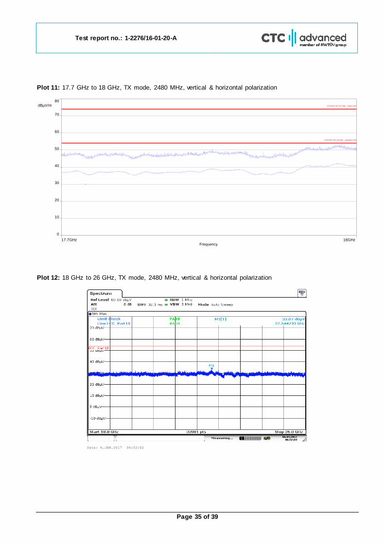
Plot 11: 17.7 GHz to 18 GHz, TX mode, 2480 MHz, vertical & horizontal polarization
Plot 12: 18 GHz to 26 GHz, TX mode, 2480 MHz, vertical & horizontal polarization
17.7GHz 18GHzFrequency
0
80 dBµV/m
50
20
70
40
10
60
30
FCC/Part 15C (15.209) - Peak/1.0m/
FCC/Part 15C (15.209) - Average/1.0m/
Date: 6.JAN.2017 06:52:02
Test report no.: 1-2276/16-01-20-A
Page 36 of 39
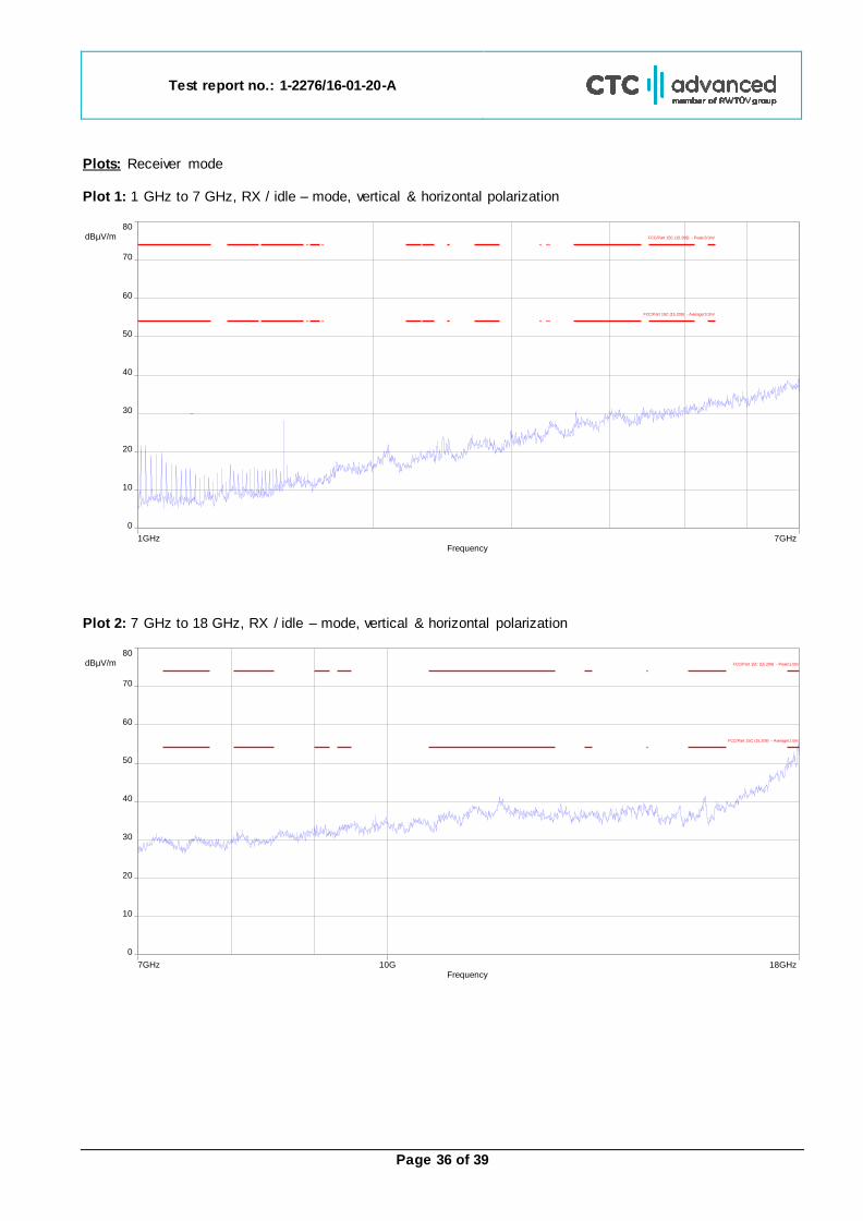
Plots: Receiver mode Plot 1: 1 GHz to 7 GHz, RX / idle – mode, vertical & horizontal polarization
Plot 2: 7 GHz to 18 GHz, RX / idle – mode, vertical & horizontal polarization
1GHz 7GHzFrequency
0
80 dBµV/m
50
20
70
40
10
60
30
FCC/Part 15C (15.209) - Peak/3.0m/
FCC/Part 15C (15.209) - QPeak/3.0m/
FCC/Part 15C (15.209) - Average/3.0m/
7GHz 18GHz10GFrequency
0
80 dBµV/m
50
20
70
40
10
60
30
FCC/Part 15C (15.209) - Peak/1.0m/
FCC/Part 15C (15.209) - Average/1.0m/
Test report no.: 1-2276/16-01-20-A
Page 37 of 39
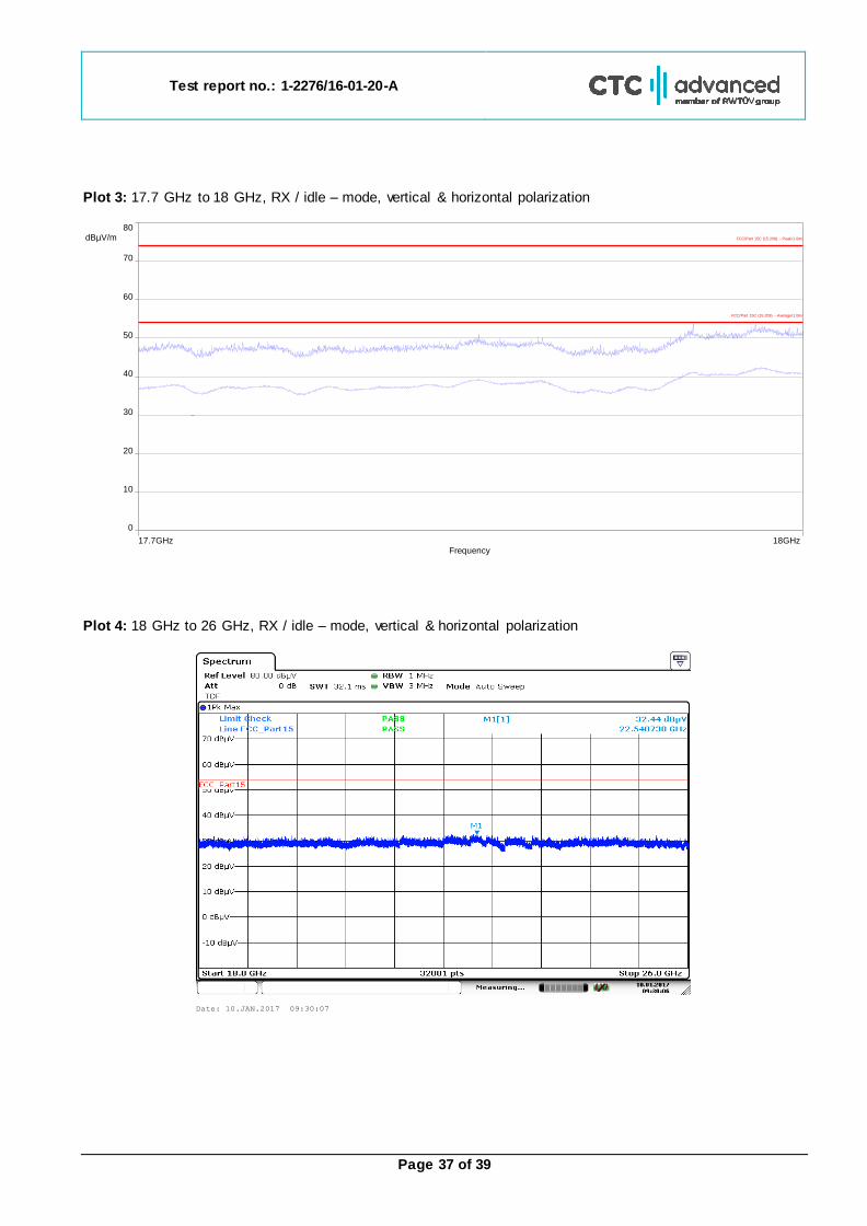
Plot 3: 17.7 GHz to 18 GHz, RX / idle – mode, vertical & horizontal polarization
Plot 4: 18 GHz to 26 GHz, RX / idle – mode, vertical & horizontal polarization
17.7GHz 18GHzFrequency
0
80 dBµV/m
50
20
70
40
10
60
30
FCC/Part 15C (15.209) - Peak/1.0m/
FCC/Part 15C (15.209) - Average/1.0m/
Date: 10.JAN.2017 09:30:07
Test report no.: 1-2276/16-01-20-A
Page 38 of 39
12 Observations No observations except those reported with the single test cases have been made.
Annex A Document history
Version Applied changes Date of release
Initial release 2017-01-10
A Editorial changes, FVIN added 2018-04-17
Annex B Further information Glossary
AVG - Average DUT - Device under test
EMC - Electromagnetic Compatibility EN - European Standard EUT - Equipment under test
ETSI - European Telecommunications Standard Institute FCC - Federal Communication Commission FCC ID - Company Identifier at FCC
HW - Hardware IC - Industry Canada Inv. No. - Inventory number
N/A - Not applicable PP - Positive peak QP - Quasi peak
S/N - Serial number SW - Software PMN - Product marketing name
HMN - Host marketing name HVIN - Hardware version identification number FVIN - Firmware version identification number
OBW Occupied Bandwidth OC Operating Channel OCW Operating Channel Bandwidth
OOB Out Of Band
Test report no.: 1-2276/16-01-20-A
Page 39 of 39
Annex C Accreditation Certificate
first page last page
Note: The current certificate annex is published on the website (link see below) of the Accreditation Body DAkkS or may be received by CTC advanced GmbH on request
http://www.dakks.de/as/ast/d/D-PL-12076-01-03.pdf