Embed Size (px)
Citation preview
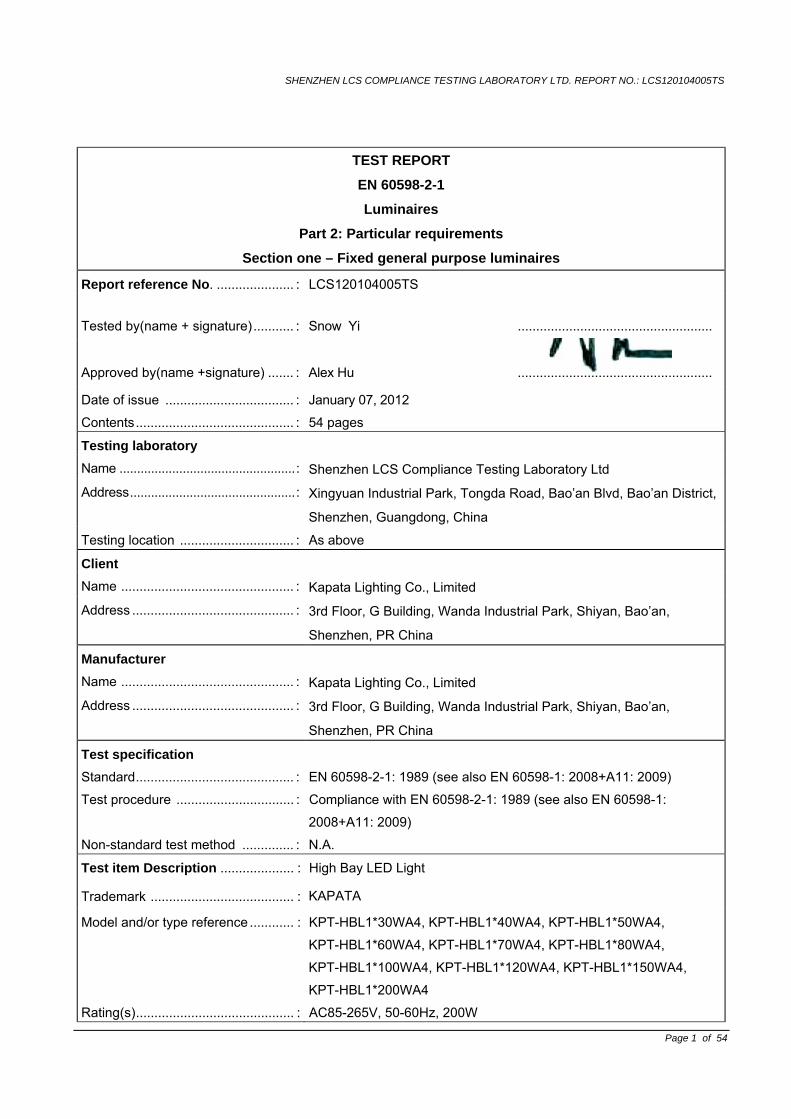
SHENZHEN LCS COMPLIANCE TESTING LABORATORY LTD. REPORT NO.: LCS120104005TS
Page 1 of 54
TEST REPORT
EN 60598-2-1
Luminaires
Part 2: Particular requirements
Section one – Fixed general purpose luminaires
Report reference No. ..................... : LCS120104005TS
Tested by(name + signature)........... : Snow Yi .....................................................
Approved by(name +signature) ....... : Alex Hu .....................................................
Date of issue ................................... : January 07, 2012
Contents........................................... : 54 pages
Testing laboratory
Name ..................................................: Shenzhen LCS Compliance Testing Laboratory Ltd
Address...............................................: Xingyuan Industrial Park, Tongda Road, Bao’an Blvd, Bao’an District,
Shenzhen, Guangdong, China
Testing location ............................... : As above
Client
Name ............................................... : Kapata Lighting Co., Limited
Address ............................................ : 3rd Floor, G Building, Wanda Industrial Park, Shiyan, Bao’an,
Shenzhen, PR China
Manufacturer
Name ............................................... : Kapata Lighting Co., Limited
Address ............................................ : 3rd Floor, G Building, Wanda Industrial Park, Shiyan, Bao’an,
Shenzhen, PR China
Test specification
Standard........................................... : EN 60598-2-1: 1989 (see also EN 60598-1: 2008+A11: 2009)
Test procedure ................................ : Compliance with EN 60598-2-1: 1989 (see also EN 60598-1:
2008+A11: 2009)
Non-standard test method .............. : N.A.
Test item Description .................... : High Bay LED Light
Trademark ....................................... : KAPATA
Model and/or type reference ............ : KPT-HBL1*30WA4, KPT-HBL1*40WA4, KPT-HBL1*50WA4,
KPT-HBL1*60WA4, KPT-HBL1*70WA4, KPT-HBL1*80WA4,
KPT-HBL1*100WA4, KPT-HBL1*120WA4, KPT-HBL1*150WA4,
KPT-HBL1*200WA4
Rating(s)........................................... : AC85-265V, 50-60Hz, 200W
SHENZHEN LCS COMPLIANCE TESTING LABORATORY LTD. REPORT NO.: LCS120104005TS
Page 2 of 54
Test item particulars
Classification of installation and use ……….: Class I
Supply Connection ………………………..…: Power cords
Test case verdicts
Test case does not apply to the test object : N(N/A)
Test item does meet the requirement ......... : P(Pass)
Test item does not meet the requirement ... : F(Fail)
Testing
Date of receipt of test item........................... : November 28, 2011
Date(s) of performance of test..................... : November 28, 2011 – January 07, 2012
General remarks
This report shall not be reproduced except in full without the written approval of the testing laboratory.
The test results presented in this report relate only to the item tested.
Clause numbers between brackets refer to clauses in EN 60598-1 (IEC 60598-1).
"(see remark #)" refers to a remark appended to the report.
"(see Annex #)" refers to an annex appended to the report.
Throughout this report a comma is used as the decimal separator.
General product information;
(1), The laboratory ambient for testing: 22.0-28.0 , 60% -73%R.H.
(2). The all models are similar except their power, appearance and LED lamp number. And all tests are base on KPT-HBL1*200WA4
(3). Attachment No. 1: Report of EN 62471 Attachment No. 2: Report of EN 62031
SHENZHEN LCS COMPLIANCE TESTING LABORATORY LTD. REPORT NO.: LCS120104005TS
Page 3 of 54
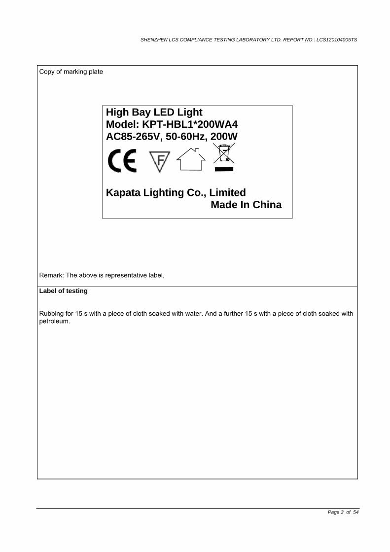
Copy of marking plate
High Bay LED Light Model: KPT-HBL1*200WA4 AC85-265V, 50-60Hz, 200W
Kapata Lighting Co., Limited Made In China
Remark: The above is representative label. Label of testing
Rubbing for 15 s with a piece of cloth soaked with water. And a further 15 s with a piece of cloth soaked with petroleum.
SHENZHEN LCS COMPLIANCE TESTING LABORATORY LTD. REPORT NO.: LCS120104005TS
EN 60598-2-1
Clause Requirement - Test Result - Remark Verdict
Page 4 of 54
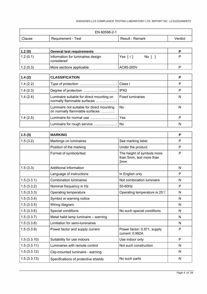
1.2 (0) General test requirements P1.2 (0.1) Information for luminaires design
considered Yes [ √ ] No [ ] P
1.2 (0.3) More sections applicable AC85-265V P 1.4 (2) CLASSIFICATION P
1.4 (2.2) Type of protection ......................................: Class I P
1.4 (2.3) Degree of protection ..................................: IPX0 P
1.4 (2.4) Luminaire suitable for direct mounting on normally flammable surfaces ……………...:
Fixed luminaries N
Luminaire not suitable for direct mounting on normally flammable surfaces ………..:
No N
1.4 (2.5) Luminaire for normal use ...........................: Yes P
Luminaire for rough service .......................: No N 1.5 (3) MARKING P
1.5 (3.2) Markings on luminaires See marking label P
Position of the marking Under the product P
Format of symbols/text The height of symbols more than 5mm, text more than 2mm
P
1.5 (3.3) Additional information N
Language of instructions In English only P
1.5 (3.3.1) Combination luminaires Not combination luminaire N
1.5 (3.3.2) Nominal frequency in Hz 50-60Hz P
1.5 (3.3.3) Operating temperature Operating temperature is 25 N
1.5 (3.3.4) Symbol or warning notice N
1.5 (3.3.5) Wiring diagram N
1.5 (3.3.6) Special conditions No such special conditions N
1.5 (3.3.7) Metal halid lamp luminaire – warning N
1.5 (3.3.8) Limitation for semi-luminaires N
1.5 (3.3.9) Power factor and supply current Power factor: 0.971, supply current: 0.992A
P
1.5 (3.3.10) Suitability for use indoors Use indoor only P
1.5 (3.3.11) Luminaires with remote control Not such construction N
1.5 (3.3.12) Clip-mounted luminaire - warning N
1.5 (3.3.13) Specifications of protective shields No such parts N
SHENZHEN LCS COMPLIANCE TESTING LABORATORY LTD. REPORT NO.: LCS120104005TS
EN 60598-2-1
Clause Requirement - Test Result - Remark Verdict
Page 5 of 54
1.5 (3.3.14) Symbol for nature of supply ~ P
1.5 (3.3.15) Rated current of socket outlet No socket outlet N
1.5 (3.3.16) Rough service luminaire Normal service luminaire N
1.5 (3.3.17) Mounting instruction for type Y, Type Z and some type X attachments
type Y P
1.5 (3.3.18) Non-ordinary luminaires with PVC cable Ordinary luminaires N
1.5 (3.3.19) Protective conductor current in instruction if applicable
P
1.5 (3.3.20) Provided with information if not intended to be mounted within arms reach
P
1.5 (3.4) Test with water 15s P
Test with hexane 15s P
Legible after test Still legible P
Label attached Still attached P
1.6 (4) CONSTRUCTION P 1.6 (4.2) Components replaceable without difficulty All parts can't be placed. N
1.6 (4.3) Wireways smooth and free from sharp edges
P
1.6 (4.4) Lampholders N
1.6 (4.4.1) Integral lampholder N
1.6 (4.4.2) Wiring connection N
1.6 (4.4.3) Lampholder for end-to-end mounting N
1.6 (4.4.4) Positioning N
- pressure test (N)…………………………..: N
After test the lampholder comply with relevant standard sheets and show no damage
N
After test on singal-capped lampholder the lampholder have not moved form its position and show no permanent deformation
N
- bending test (N)……………………………: N
After test the lamholder have not moved from its position and show no permanent deformation
N
1.6 (4.4.5) Peak pulse voltage No ignitors N
1.6 (4.4.6) Centre contact No ignitors N
SHENZHEN LCS COMPLIANCE TESTING LABORATORY LTD. REPORT NO.: LCS120104005TS
EN 60598-2-1
Clause Requirement - Test Result - Remark Verdict
Page 6 of 54
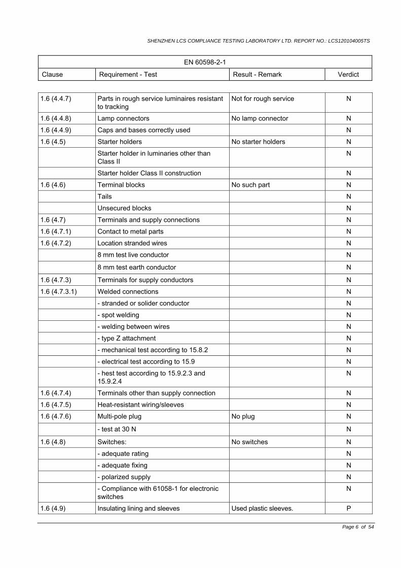
1.6 (4.4.7) Parts in rough service luminaires resistant to tracking
Not for rough service N
1.6 (4.4.8) Lamp connectors No lamp connector N
1.6 (4.4.9) Caps and bases correctly used N
1.6 (4.5) Starter holders No starter holders N
Starter holder in luminaries other than Class II
N
Starter holder Class II construction N
1.6 (4.6) Terminal blocks No such part N
Tails N
Unsecured blocks N
1.6 (4.7) Terminals and supply connections N
1.6 (4.7.1) Contact to metal parts N
1.6 (4.7.2) Location stranded wires N
8 mm test live conductor N
8 mm test earth conductor N
1.6 (4.7.3) Terminals for supply conductors N
1.6 (4.7.3.1) Welded connections N
- stranded or solider conductor N
- spot welding N
- welding between wires N
- type Z attachment N
- mechanical test according to 15.8.2 N
- electrical test according to 15.9 N
- hest test according to 15.9.2.3 and 15.9.2.4
N
1.6 (4.7.4) Terminals other than supply connection N
1.6 (4.7.5) Heat-resistant wiring/sleeves N
1.6 (4.7.6) Multi-pole plug No plug N
- test at 30 N N
1.6 (4.8) Switches: No switches N
- adequate rating N
- adequate fixing N
- polarized supply N
- Compliance with 61058-1 for electronic switches
N
1.6 (4.9) Insulating lining and sleeves Used plastic sleeves. P
SHENZHEN LCS COMPLIANCE TESTING LABORATORY LTD. REPORT NO.: LCS120104005TS
EN 60598-2-1
Clause Requirement - Test Result - Remark Verdict
Page 7 of 54
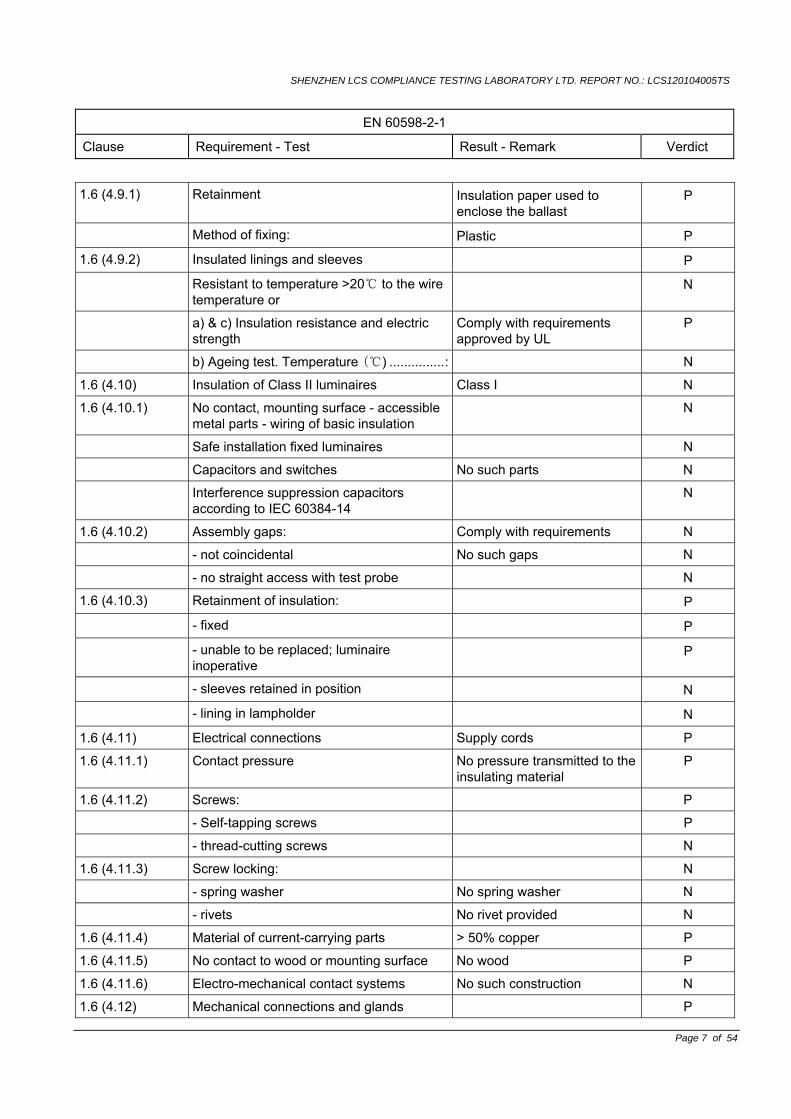
1.6 (4.9.1) Retainment Insulation paper used to enclose the ballast
P
Method of fixing: Plastic P
1.6 (4.9.2) Insulated linings and sleeves P
Resistant to temperature >20 to the wire temperature or
N
a) & c) Insulation resistance and electric strength
Comply with requirements approved by UL
P
b) Ageing test. Temperature () ...............: N
1.6 (4.10) Insulation of Class II luminaires Class I N
1.6 (4.10.1) No contact, mounting surface - accessible metal parts - wiring of basic insulation
N
Safe installation fixed luminaires N
Capacitors and switches No such parts N
Interference suppression capacitors according to IEC 60384-14
N
1.6 (4.10.2) Assembly gaps: Comply with requirements N
- not coincidental No such gaps N
- no straight access with test probe N
1.6 (4.10.3) Retainment of insulation: P
- fixed P
- unable to be replaced; luminaire inoperative
P
- sleeves retained in position N
- lining in lampholder N
1.6 (4.11) Electrical connections Supply cords P
1.6 (4.11.1) Contact pressure No pressure transmitted to the insulating material
P
1.6 (4.11.2) Screws: P
- Self-tapping screws P
- thread-cutting screws N
1.6 (4.11.3) Screw locking: N
- spring washer No spring washer N
- rivets No rivet provided N
1.6 (4.11.4) Material of current-carrying parts > 50% copper P
1.6 (4.11.5) No contact to wood or mounting surface No wood P
1.6 (4.11.6) Electro-mechanical contact systems No such construction N
1.6 (4.12) Mechanical connections and glands P
SHENZHEN LCS COMPLIANCE TESTING LABORATORY LTD. REPORT NO.: LCS120104005TS
EN 60598-2-1
Clause Requirement - Test Result - Remark Verdict
Page 8 of 54
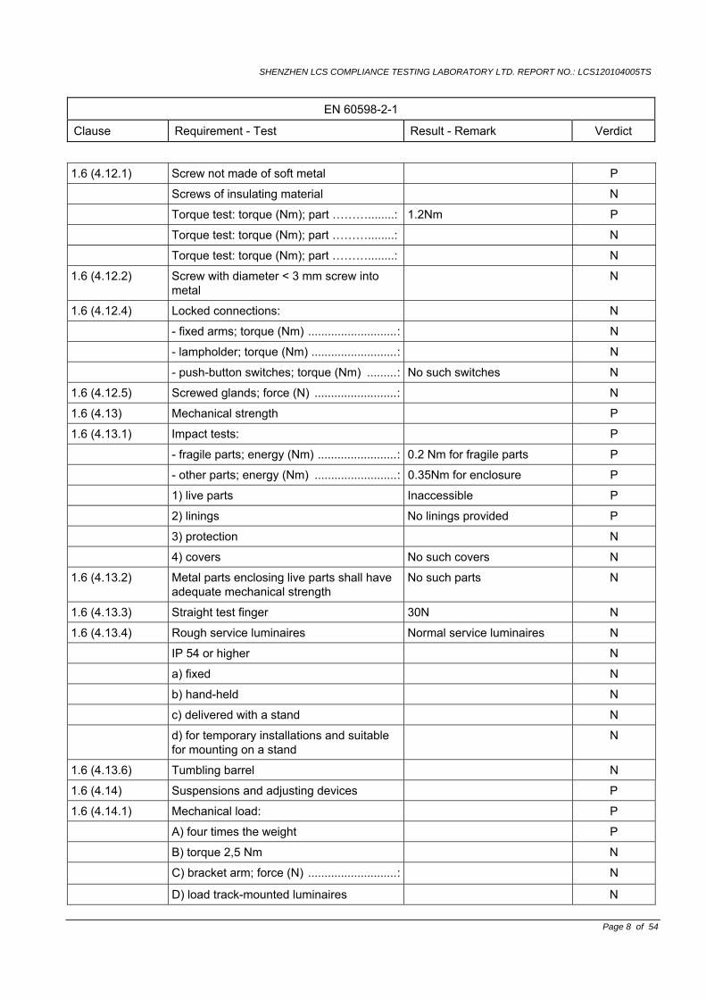
1.6 (4.12.1) Screw not made of soft metal P
Screws of insulating material N
Torque test: torque (Nm); part ………........: 1.2Nm P
Torque test: torque (Nm); part ………........: N
Torque test: torque (Nm); part ………........: N
1.6 (4.12.2) Screw with diameter < 3 mm screw into metal
N
1.6 (4.12.4) Locked connections: N
- fixed arms; torque (Nm) ...........................: N
- lampholder; torque (Nm) ..........................: N
- push-button switches; torque (Nm) .........: No such switches N
1.6 (4.12.5) Screwed glands; force (N) .........................: N
1.6 (4.13) Mechanical strength P
1.6 (4.13.1) Impact tests: P
- fragile parts; energy (Nm) ........................: 0.2 Nm for fragile parts P
- other parts; energy (Nm) .........................: 0.35Nm for enclosure P
1) live parts Inaccessible P
2) linings No linings provided P
3) protection N
4) covers No such covers N
1.6 (4.13.2) Metal parts enclosing live parts shall have adequate mechanical strength
No such parts N
1.6 (4.13.3) Straight test finger 30N N
1.6 (4.13.4) Rough service luminaires Normal service luminaires N
IP 54 or higher N
a) fixed N
b) hand-held N
c) delivered with a stand N
d) for temporary installations and suitable for mounting on a stand
N
1.6 (4.13.6) Tumbling barrel N
1.6 (4.14) Suspensions and adjusting devices P
1.6 (4.14.1) Mechanical load: P
A) four times the weight P
B) torque 2,5 Nm N
C) bracket arm; force (N) ...........................: N
D) load track-mounted luminaires N
SHENZHEN LCS COMPLIANCE TESTING LABORATORY LTD. REPORT NO.: LCS120104005TS
EN 60598-2-1
Clause Requirement - Test Result - Remark Verdict
Page 9 of 54
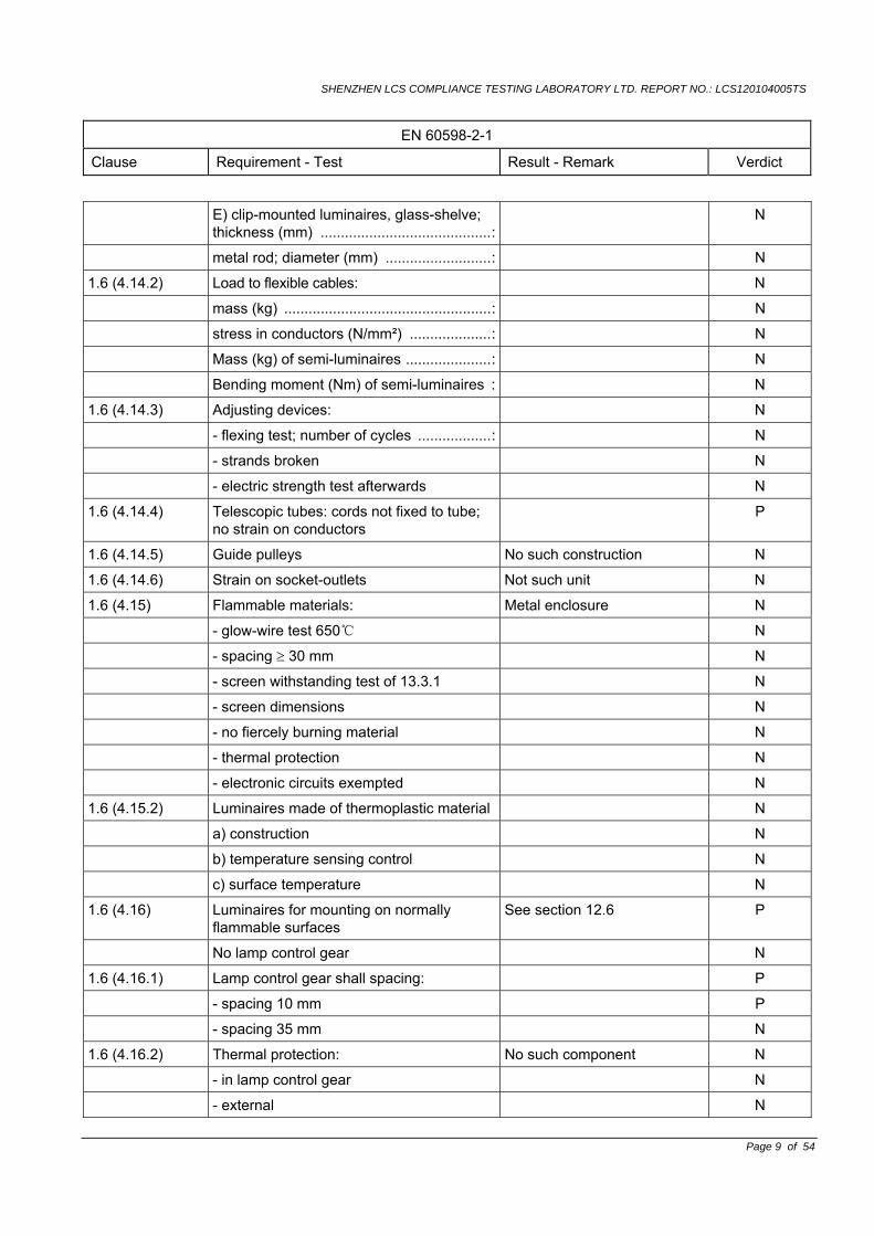
E) clip-mounted luminaires, glass-shelve; thickness (mm) ..........................................:
N
metal rod; diameter (mm) ..........................: N
1.6 (4.14.2) Load to flexible cables: N
mass (kg) ...................................................: N
stress in conductors (N/mm²) ....................: N
Mass (kg) of semi-luminaires .....................: N
Bending moment (Nm) of semi-luminaires : N
1.6 (4.14.3) Adjusting devices: N
- flexing test; number of cycles ..................: N
- strands broken N
- electric strength test afterwards N
1.6 (4.14.4) Telescopic tubes: cords not fixed to tube; no strain on conductors
P
1.6 (4.14.5) Guide pulleys No such construction N
1.6 (4.14.6) Strain on socket-outlets Not such unit N
1.6 (4.15) Flammable materials: Metal enclosure N
- glow-wire test 650 N
- spacing ≥ 30 mm N
- screen withstanding test of 13.3.1 N
- screen dimensions N
- no fiercely burning material N
- thermal protection N
- electronic circuits exempted N
1.6 (4.15.2) Luminaires made of thermoplastic material N
a) construction N
b) temperature sensing control N
c) surface temperature N
1.6 (4.16) Luminaires for mounting on normally flammable surfaces
See section 12.6 P
No lamp control gear N
1.6 (4.16.1) Lamp control gear shall spacing: P
- spacing 10 mm P
- spacing 35 mm N
1.6 (4.16.2) Thermal protection: No such component N
- in lamp control gear N
- external N
SHENZHEN LCS COMPLIANCE TESTING LABORATORY LTD. REPORT NO.: LCS120104005TS
EN 60598-2-1
Clause Requirement - Test Result - Remark Verdict
Page 10 of 54
- fixed position N
- temperature marked lamp control gear N
1.6 (4.16.3) Design to satisfy the test of 12.6 N
1.6 (4.17) Drain holes No drain holes N
Clearance at least 5 mm N
1.6 (4.18) Resistance to corrosion: P
1.6 (4.18.1) - rust-resistance Painted with rust-resistance material
P
1.6 (4.18.2) - season cracking in copper P
1.6 (4.18.3) - corrosion of aluminium No aluminium used N
1.6 (4.19) Ignitors compatible with ballast No ignitors used N
1.6 (4.20) Rough service vibration .............................: Not such appliance N
1.6 (4.21) Protective shield N
1.6 (4.21.1) Shield fitted N
Shield of glass if tungsten halogen lamps N
1.6 (4.21.2) Particles from a shattering lamp not impair safety
N
1.6 (4.21.3) No direct path N
1.6 (4.21.4) Impact test on shield N
Glow-wire test on lamp compartment N
1.6 (4.22) Attachments to lamps No such attachments N
1.6 (4.23) Semi-luminaires comply with Class II Not such appliance N
1.6 (4.24) UV radiation for tungsten halogen lamps and metal halide lamps (Annex P)
No such appliance N
1.6 (4.25) No sharp point edges No sharp points or edges P
1.6 (4.26) Short-circuit protection No SELV parts N
1.6 (4.26.1) Uninsulated accessible SELV parts N
1.6 (4.26.2) Short circuit test N
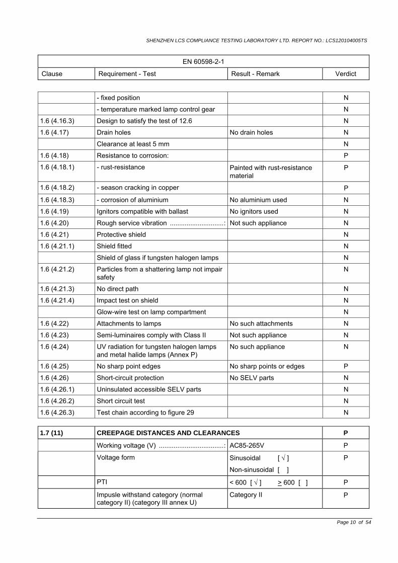
1.6 (4.26.3) Test chain according to figure 29 N 1.7 (11) CREEPAGE DISTANCES AND CLEARANCES P
Working voltage (V) ...................................: AC85-265V P
Voltage form Sinusoidal [ √ ]
Non-sinusoidal [ ]
P
PTI < 600 [ √ ] > 600 [ ] P
Impusle withstand category (normal category II) (category III annex U)
Category II P
SHENZHEN LCS COMPLIANCE TESTING LABORATORY LTD. REPORT NO.: LCS120104005TS
EN 60598-2-1
Clause Requirement - Test Result - Remark Verdict
Page 11 of 54
Rated pulse voltage (kV) ...........................: <2.0kV P
(1) Current-carrying parts of different polarity: cr (mm); cl (mm) ...........................:
cl>5.0mm, limit: 1.5mm cr>5.2mm, limit: 2.5mm
P
(2) Current-carrying parts and accessible parts:cr (mm); cl (mm) ...............................:
cl>5.0mm, limit: 1.5mm cr>5.2mm, limit: 2.5mm
P
(3) Parts becoming live due to breakdown of basic insulation and metal parts: cr (mm); cl (mm) ............................................:
N
(4) Outer surface of cable where it is clamp and metal parts: cr (mm); cl (mm) .............:
N
(5)not used N
(6) Current-carrying parts and supporting surface: cr (mm); cl (mm) ...........................:
cl>5.0mm, limit: 1.5mm cr>5.2mm, limit: 2.5mm
P
1.8 (7) PROVISION FOR EARTHING Class I appliances P
1.8 (7.2.1 + 7.2.3)
Accessible Metal parts P
Metal parts in contact with supporting surface
P
Resistance < 0.5 Ω 0.26Ω P
Self-tapping screws used P
Thread-forming screws N
Thread-forming screws used in a grove N
Earth marks contact first P
1.8 (7.2.2 +7.2.3) Earth continuity in joints etc. P
1.8 (7.2.4) Locking of clamping means N
Compliance with 4.7.3 N
Terminal blocks with integrated screwless earthing contacts tested according Annex V
N
1.8 (7.2.5) Earth terminal integral part of Connector socket
N
1.8 (7.2.6) Earth terminal adjacent to mains terminals P
1.8 (7.2.7) Electrolytic Corrosion of the earth terminal P
1.8 (7.2.8) Material of earth terminal P
Contact surface bare metal P
1.8 (7.2.10) Class II luminaire for looping-in N
SHENZHEN LCS COMPLIANCE TESTING LABORATORY LTD. REPORT NO.: LCS120104005TS
EN 60598-2-1
Clause Requirement - Test Result - Remark Verdict
Page 12 of 54
Double or reinforced insulation to functional earth
N
1.8 (7.2.11) Earthing core coloured green-yellow P
Length of earth conductor P
1.9 (14) SCREW TERMINALS N
Separately approved: component list See annex 1 P
Part of the luminaire See annex 3 N 1.9 (15) SCREWLESS TERMINALS and electrical connections N
Separately approved: component list See annex 1 P
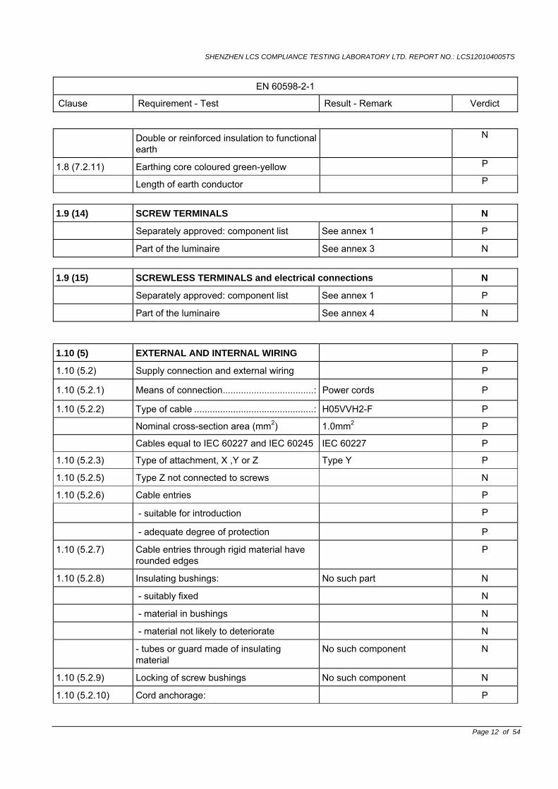
Part of the luminaire See annex 4 N 1.10 (5) EXTERNAL AND INTERNAL WIRING P
1.10 (5.2) Supply connection and external wiring P
1.10 (5.2.1) Means of connection...................................: Power cords P
1.10 (5.2.2) Type of cable ..............................................: H05VVH2-F P
Nominal cross-section area (mm2) 1.0mm2 P
Cables equal to IEC 60227 and IEC 60245 IEC 60227 P
1.10 (5.2.3) Type of attachment, X ,Y or Z Type Y P
1.10 (5.2.5) Type Z not connected to screws N
1.10 (5.2.6) Cable entries P
- suitable for introduction P
- adequate degree of protection P
1.10 (5.2.7) Cable entries through rigid material have rounded edges
P
1.10 (5.2.8) Insulating bushings: No such part N
- suitably fixed N
- material in bushings N
- material not likely to deteriorate N
- tubes or guard made of insulating material
No such component N
1.10 (5.2.9) Locking of screw bushings No such component N
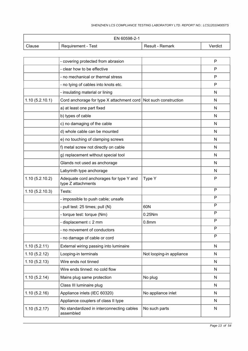
1.10 (5.2.10) Cord anchorage: P
SHENZHEN LCS COMPLIANCE TESTING LABORATORY LTD. REPORT NO.: LCS120104005TS
EN 60598-2-1
Clause Requirement - Test Result - Remark Verdict
Page 13 of 54
- covering protected from abrasion P
- clear how to be effective P
- no mechanical or thermal stress P
- no tying of cables into knots etc. P
- insulating material or lining N
1.10 (5.2.10.1) Cord anchorage for type X attachment cord Not such construction N
a) at least one part fixed N
b) types of cable N
c) no damaging of the cable N
d) whole cable can be mounted N
e) no touching of clamping screws N
f) metal screw not directly on cable N
g) replacement without special tool N
Glands not used as anchorage N
Labyrinth type anchorage N
1.10 (5.2.10.2) Adequate cord anchorages for type Y and type Z attachments
Type Y P
1.10 (5.2.10.3) Tests: P
- impossible to push cable; unsafe P
- pull test: 25 times; pull (N) 60N P
- torque test: torque (Nm) 0.25Nm P
- displacement ≤ 2 mm 0.8mm P
- no movement of conductors P
- no damage of cable or cord P
1.10 (5.2.11) External wiring passing into luminaire N
1.10 (5.2.12) Looping-in terminals Not looping-in appliance N
1.10 (5.2.13) Wire ends not tinned N
Wire ends tinned: no cold flow N
1.10 (5.2.14) Mains plug same protection No plug N
Class III luminaire plug N
1.10 (5.2.16) Appliance inlets (IEC 60320) No appliance inlet N
Appliance couplers of class II type N
1.10 (5.2.17) No standardized in interconnecting cables assembled
No such parts N
SHENZHEN LCS COMPLIANCE TESTING LABORATORY LTD. REPORT NO.: LCS120104005TS
EN 60598-2-1
Clause Requirement - Test Result - Remark Verdict
Page 14 of 54
1.10 (5.2.18) Used plug in accordance with No plug N
- IEC 60083 N
- other standard N
1.10 (5.3) Internal wiring P
1.10 (5.3.1) Internal wiring of suitable size and type 1007 P
Through wiring N
- not delivered/ mounting instruction N
- factory assembled N
- socket outlet loaded (A)............................: N
- temperatures ............................................: N
Green-yellow for earth only P
1.10 (5.3.1.1) Internal wiring connected directly to fixed wiring P
Cross-Sectional area (mm2) >0.4 mm2 P
Insulation thickness >0.5mm P
Extra insulation added where necessary N
1.10 (5.3.1.2) Internal wiring connected to fixed wiring via internal current-limited device
N
Adequate cross-section area and insulation thickness
N
1.10 (5.3.1.3) Double or reinforced insulation for class II N
1.10 (5.3.1.4) Conductors without insulation N
1.10 (5.3.1.5) SELV current-carrying parts No such parts N
1.10 (5.3.1.6) Insulation thickness other than PVC or rubber
P
1.10 (5.3.2) Sharp edges etc. P
No moving parts of switches etc. P
Joints, raising/lowering devices P
Telescopic tubes etc. N
No twisting over 3600 N
1.10 (5.3.3) Insulating bushings N
- suitable fixed N
- material in bushings N
- material not likely to deteriorate N
- cables with protective sheath N
SHENZHEN LCS COMPLIANCE TESTING LABORATORY LTD. REPORT NO.: LCS120104005TS
EN 60598-2-1
Clause Requirement - Test Result - Remark Verdict
Page 15 of 54
1.10 (5.3.4) Joints and Junctions effectively insulated N
1.10 (5.3.5) Strain on internal wiring N
1.10 (5.3.6) Wire carriers N
1.10 (5.3.7) Wire ends not tinned N
Wire ends tinned: no cold flow N
1.11 (8) PROTECTION AGAINST ELECTRIC SHOCK P
1.11 (8.2.1) Live parts not accessible with standard test finger
Live parts enclosed by plastic enclosure and metal enclosure
P
Basic insulated parts not used on the outer surface without appropriate protection
P
Basic insulated parts not accessible with standard test finger on portable and adjustable luminaires
N
Basic insulated parts not accessible with ø50mm probe from outside, within arms reach, on wall-mounted luminaires
P
Lamp and startholders in portable and adjustable luminaires comply with double or reinforced insulation requirements
N
Basic insulation only accessible under lamp or starter replacement
N
Double-ended tungsten filament lamp N
Insulation lacquer not reliable P
Double-ended high pressure discharge lamp
N
Relevant warming according to 3.2.18 fitted to the luminaire
P
1.11 (8.2.2) Portable luminaire adjusted in most unfavourable position
Fixed luminaire N
1.11 (8.2.3 a) Class II luminaire: N
- basic insulated metal parts not accessible during starter or lamp replacement
N
- basic insulated not accessible other than during starter or lamp replacement
N
- glass protective shields not used as supplementary insulation
N
1.11 (8.2.3b) BC lampholder of metal in class I luminaires shall be earthed
N
SHENZHEN LCS COMPLIANCE TESTING LABORATORY LTD. REPORT NO.: LCS120104005TS
EN 60598-2-1
Clause Requirement - Test Result - Remark Verdict
Page 16 of 54
1.11 (8.2.3c) Class III luminaires with expose SELV parts:
Class II luminaires N
Ordinary luminaire : N
- touch current N
- no-load voltage N
- other than ordinary luminaire: N
- nominal voltage N
1.11 (8.2.4) Portable luminaire: Fixed luminaire N
- protection independent of supporting surface
N
- terminal block completely covered N
1.11 (8.2.5) Compliance with the standard test finger or relevant probe
P
1.11 (8.2.6) Covers reliably secured P
1.11 (8.2.7) Discharging of capacitors >0,5 μF P
Portable plug connected luminaire with capacitor
N
Discharge device on or within capacitor N
Discharge device mounted separately N
1.11.1 (-) Protective parts for lamp caps not removable by hand in hand-held inspection luminaires
N
1.11.2 (-) Fixing of parts within 2 m from floor P 1.12 (12) ENDURANCE TEST AND THERMAL TEST P
1.12 (12.3) Endurance test: P
- mounting-position ....................................: Wall P
- test temperature (°C) ...............................: 35ºC P
- total duration (h) ......................................: 240hrs. Totally 10 cycles, each 24h. Appliance worked as normal
P
- supply voltage: Un factor; calculated voltage (V) ..................................................:
265VX1.1 P
- lamp used ................................................: LED lamp P
1.12 (12.3.2) After endurance test: P
- no part unserviceable P
- luminaire not unsafe P
- no damage to track system N
SHENZHEN LCS COMPLIANCE TESTING LABORATORY LTD. REPORT NO.: LCS120104005TS
EN 60598-2-1
Clause Requirement - Test Result - Remark Verdict
Page 17 of 54
- marking legible P
- no cracks, deformation etc. P
1.12 (12.4) Thermal test (normal operation) (see table 12.4 ) P
1.12 (12.5) Thermal test (abnormal operation) P
Short-circuit of starter contacts N
Lamps removed and not replaced N
1.12 (12.6) Thermal test (failed lamp control gear condition):
N
1.12 (12.6.1) Through wiring or looping-in wiring loaded by a current of (A)
N
- case of abnormal conditions ....................: N
- electronic ballast N
- measured winding temperature (°C): at 1,1 Un
N
- measured mounting surface temperature (°C): at 1,1 Un ............................................:
N
- calculated mounting surface temperature(°C)
N
- track-mounted luminaires N
1.12 (12.6.2) Temperature sensing control: N
- manual reset cut-out N
- auto reset cut-out N
- track-mounted luminaires N
1.12 (12.7) Thermal test (failed ballast or transformer in plastic luminaires): N
1.12 (12.7.1) Luminaire without temperature sensing control
N
1.12 (12.7.1.1) Luminaire with fluorescent lamp ≤ 70W N
Test method 12.7.1.1 or Annex V N
Test according to 12.7.1.1: N
- case of abnormal conditions N
- Ballast failure at supply voltage (V) N
- Components retained in place after the test
N
- Test with standard test finger after the test
N
Test according to Annex V: N
- case of abnormal conditions N
SHENZHEN LCS COMPLIANCE TESTING LABORATORY LTD. REPORT NO.: LCS120104005TS
EN 60598-2-1
Clause Requirement - Test Result - Remark Verdict
Page 18 of 54
- measured winding temperature (): at 1,1 Un.. :
N
- measured temperature of fixing point/exposed part (): at 1,1Un.............. :
N
- calculated temperature of fixing point/exposed part () ............................:
N
Ball-pressure test: N
- part tested; temperature ()................ : N
- part tested; temperature ()................. : N
1.12 (12.7.1.2) Luminaire with discharge lamp, fluorescent lamp > 70W, transformer > 10 VA
N
- case of abnormal conditions N
- measured winding temperature (): at 1,1 Un.. :
N
- measured temperature of fixing point/exposed part (): at 1,1 Un.......... :
N
- calculated temperature of fixing point/exposed part () .... :
N
Ball-pressure test: N
- part tested; temperature ()............ : N
- part tested; temperature ()................ : N
1.12 (12.7.1.3) Luminaire with short circuit proof transformers ≤ 10 VA
N
- case of abnormal conditions N
- Components retained in place after the test
N
- Test with standard test finger after the test
N
1.12 (12.7.2) Luminaire with temperature sensing control N
- thermal link N
- manual reset cut-out N
- auto reset cut-out N
- case of abnormal conditions N
- highest measured temperature of fixing
point/exposed part ():.......................... :
N
Ball-pressure test: N
- part tested; temperature ()................ : N
- part tested; temperature ()................ : N
SHENZHEN LCS COMPLIANCE TESTING LABORATORY LTD. REPORT NO.: LCS120104005TS
EN 60598-2-1
Clause Requirement - Test Result - Remark Verdict
Page 19 of 54
1.13 (9) RESISTANCE TO DUST, SOLID OBJECTS AND MOISTURE P
1.12 (9.2) Tests for ingress of dust, solid objects and moisture: P
- classification according to IP ...................: IPX0 P
- mounting position during test ..................: N
- fixing screws tightened; torque (Nm) .......: N
- tests according to clauses .......................: N
- electric strength N
a) no deposit in dust-proof luminaire N
b) no talcum in dust-tight luminaire N
c) no trace of water on current-carrying parts or SELV parts or where it could become a hazard
N
d) i) For luminaires without drain holes – no water entry
N
d) ii) For luminaires with drain holes – no
hazardous water entry
N
e) no water in watertight luminaire N
f ) no contact with live parts (IP 2X) N
f) no entry into enclosure (IP 3X and IP 4X) N
f) no contact with live parts (IP3X and IP4X)
N
g) no trace of water on part of lamp requiring protection from splashing water
N
h) no damage of protective shield or glass envelope
N
1.13 (9.3) Humidity test 48h Relative humidity 93%, temperature 25 , 48h, followed by hi-pot test
P
1.13.1 (-) Parts removed before humidity treatment -- 1.14 (10) INSULATION RESISTANCE AND ELECTRIC STRENGTH P
1.14 (10.2.1) Insulation resistance test: P
Cable or cord covered by metal foil or replaced by a metal rod of mm Ø ............. :
Class I N
Insulation resistance: P
SELV: --
- between current-carrying parts of differentpolarity....................................................... :
N
- between current-carrying parts and No switches N
SHENZHEN LCS COMPLIANCE TESTING LABORATORY LTD. REPORT NO.: LCS120104005TS
EN 60598-2-1
Clause Requirement - Test Result - Remark Verdict
Page 20 of 54
mounting surface ....................... : - between current-carrying parts and metal
parts of the luminaire ............................... : N
Other than SELV: --
- between live parts of different polarity .... : >100 MΩ, limits: 2 MΩ P
- between live parts and mounting surface : N
- between live parts and metal parts.......... : >100 MΩ, limits: 2 MΩ P
- between live parts of different polarity through action of a switch ........................ :
N
1.14 (10.2.2) Electric strength test: P
Dummy lamp N
Luminaires with ignitors after 24 h test N
Luminaires with manual ignitors N
Test voltage (V): P
SELV: --
- between current-carrying parts of differentpolarity........................................................ :
N
- between current-carrying parts and mounting surface ..................... :
N
- between current-carrying parts and metal parts of the luminaire ............................... :
N
Other than SELV: --
- between live parts of different polarity .... : 1530Vac, 1min, no breakdown P
- between live parts and mounting surface : N
- between live parts and metal parts.......... : 1530Vac, 1min, no breakdown P
1.14 (10.3) Touch current (mA) ..................................: 0.15mA, limits: 3.5mA P 1.15 (13) RESISTANCE TO HEAT, FIRE AND TRACKING N
1.15 (13.2.1) Ball-pressure test: N
- part tested; temperature (°C) ...................: N
- part tested; temperature (°C) ...................: N
1.15 (13.3.1) Needle flame test (10 s): N
- part tested ................................................: N
- part tested ................................................: N
1.15 (13.3.2) Glow-wire test (650 °C): N - part tested ................................................: N
SHENZHEN LCS COMPLIANCE TESTING LABORATORY LTD. REPORT NO.: LCS120104005TS
EN 60598-2-1
Clause Requirement - Test Result - Remark Verdict
Page 21 of 54
- part tested ................................................: N
1.15 (13.4.2) Tracking test: part tested ...........................: No burning N CENELEC COMMON MODIFICATIONS (EN) --
1.5 (3) MARKING --
1.5.(3.3.301) Adequate warning on the package ⎯
1.10 (5) EXTERNAL AND INTERNAL WIRING ⎯
1.10 (5.2.1) Connecting leads N
- without a means for connection to the supply
N
- terminal block specified N
- relevant information provided N
- compliance with 4.6, 4.7.1, 4.7.2, 4.10.1, 11.2,12 and 13.2 of Part 1
N
1.10 (5.2.2) Cables equal to HD21 S2 or HD22 S2 N ZB ANNEX ZB, SPECIAL NATIONAL
CONDITIONS (EN) N
(3.3) DK: power supply cord with label N
IT: warning label on Class 0 luminaire N
(4.5.1) DK: socket-outlets N
(5.2.1) CY, DK, FI, SE, GB: type of plug N ZC ANNEX ZC, NATIONAL DEVIATIONS
(EN) N
(4&5) FR: Shuttered socket-outlets 10/16A N
(13.3) GB: Requirements according to United Kingdom Building Regulation
N
(13.3.2) FR: Glow-wire test 850 alt. 750 for luminaires in premises open to public or 960 for luminaires in emergency exits
N
SHENZHEN LCS COMPLIANCE TESTING LABORATORY LTD. REPORT NO.: LCS120104005TS
Tables
Page 22 of 54
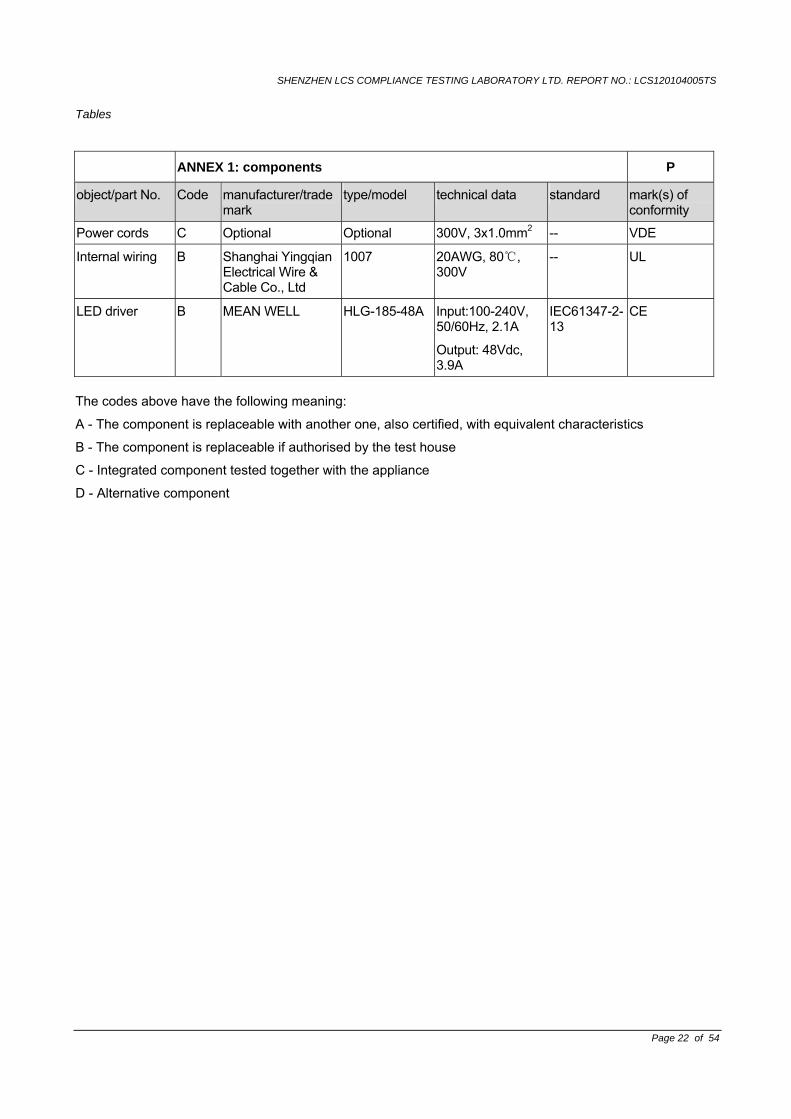
ANNEX 1: components P
object/part No. Code manufacturer/trademark
type/model technical data standard mark(s) of conformity
Power cords C Optional Optional 300V, 3x1.0mm2 -- VDE
Internal wiring B Shanghai Yingqian Electrical Wire & Cable Co., Ltd
1007 20AWG, 80 , 300V
-- UL
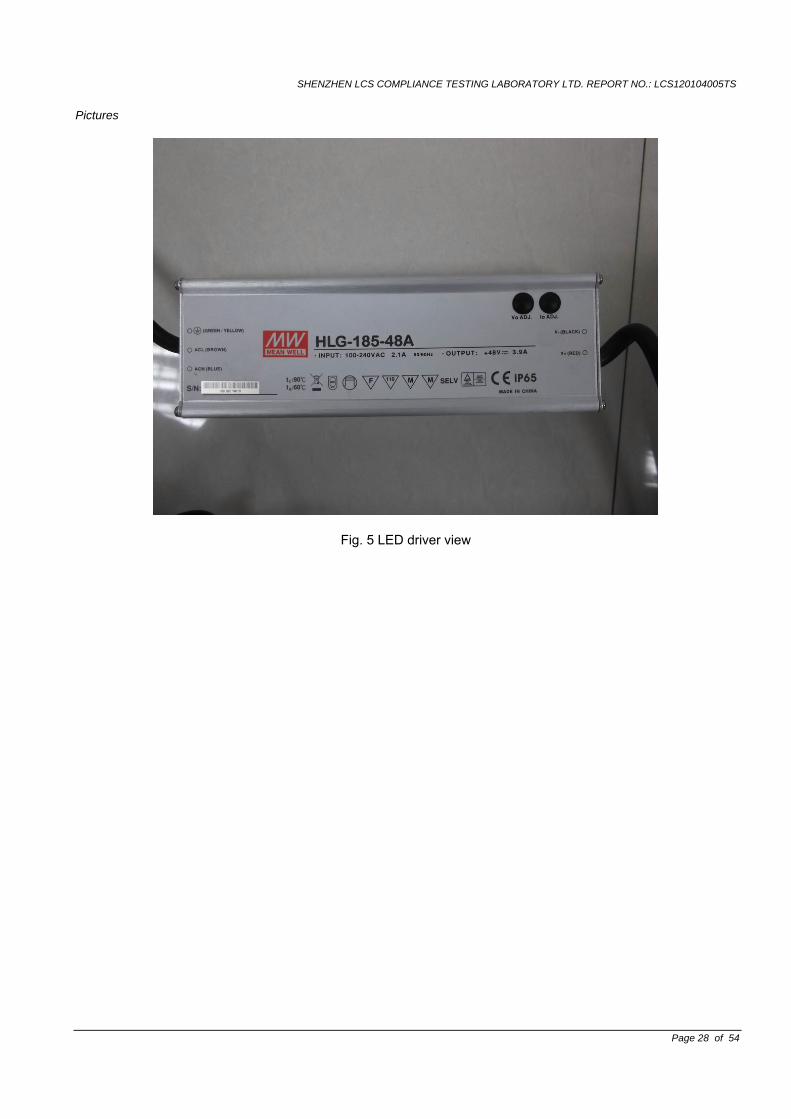
LED driver B MEAN WELL HLG-185-48A Input:100-240V, 50/60Hz, 2.1A
Output: 48Vdc, 3.9A
IEC61347-2-13
CE
The codes above have the following meaning:
A - The component is replaceable with another one, also certified, with equivalent characteristics
B - The component is replaceable if authorised by the test house
C - Integrated component tested together with the appliance
D - Alternative component
SHENZHEN LCS COMPLIANCE TESTING LABORATORY LTD. REPORT NO.: LCS120104005TS
Tables
Page 23 of 54
ANNEX 2: temperature measurements, thermal tests of Section 12 P
Type reference ………………………………….…..: KPT-HBL1*200WA4 P
Lamp used ………………………………….……....: LED lamp P
Lamp control gear used………………………….........: Built-in model name: HLG-185-48A
P
Mounting position of luminaire………………………..: See product manual P
Supply wattage (W) ………………………….……….: 200W P
Supply current (A) ……………………………..……….: 1.0A P
Calculated power factor………………………………..: P
Table: measured temperatures corrected for ta = 25: P
- abnormal operating mode…………….……..……….: N.A. N
- test 1: rated voltage……………………..…………...: 265V P
- test 2: 1,06 times rated voltage or 1,05 times Rated wattage …………………………………….………..…:
265x1.06V P
- test 3: Load on wiring to socket-outlet, 1.06 times voltage or 1.05 times wattage ..................................:
-- N
- test 4: 1,1 times rated voltage or 1,05 times rated wattage .............................................................:
N
Through wiring or looping-in wiring loaded by acurrent of A during the test ......................................:
-- N
Clause 12.4 - normal Clause 12.5 - abnormal
Temperature() of part Test 1 Test 2 Test 3 Limits() Test 4 Limit
()
Internal wire -- 67.6 -- 90 -- --
LED driver enclosure -- 62.5 -- 90 -- --
Metal Enclosure, outside -- 73.4 -- 90 -- --
Mounting surface -- 27.6 -- 90 -- --
Ambient -- 24.5 -- -- -- -- ANNEX 3: screw terminals (part of the luminaire) --
(14) SCREW TERMINALS --
(14.2) Type of terminal.......................................... : ⎯
Rated current (A)........................................ : ⎯
(14.3.2.1) One or more conductors N
(14.3.2.2) Special preparation N
(14.3.2.3) Terminal size N
Cross-sectional area (mm²)........................ : N
(14.3.3) Conductor space (mm)............................... : N
(14.4) Mechanical tests N
SHENZHEN LCS COMPLIANCE TESTING LABORATORY LTD. REPORT NO.: LCS120104005TS
Tables
Page 24 of 54
(14.4.1) Minimum distance N
(14.4.2) Cannot slip out N
(14.4.3) Special preparation N
(14.4.4) Nominal diameter of thread (metric ISO thread) ........................................................ :
N
External wiring N
No soft metal N
(14.4.5) Corrosion N
(14.4.6) Nominal diameter of thread (mm) .............. : N
Torque (Nm) ............................................... : N
(14.4.7) Between metal surfaces N
Lug terminal N
Mantle terminal N
Pull test; pull (N) ......................................... : N
(14.4.8) Without undue damage N
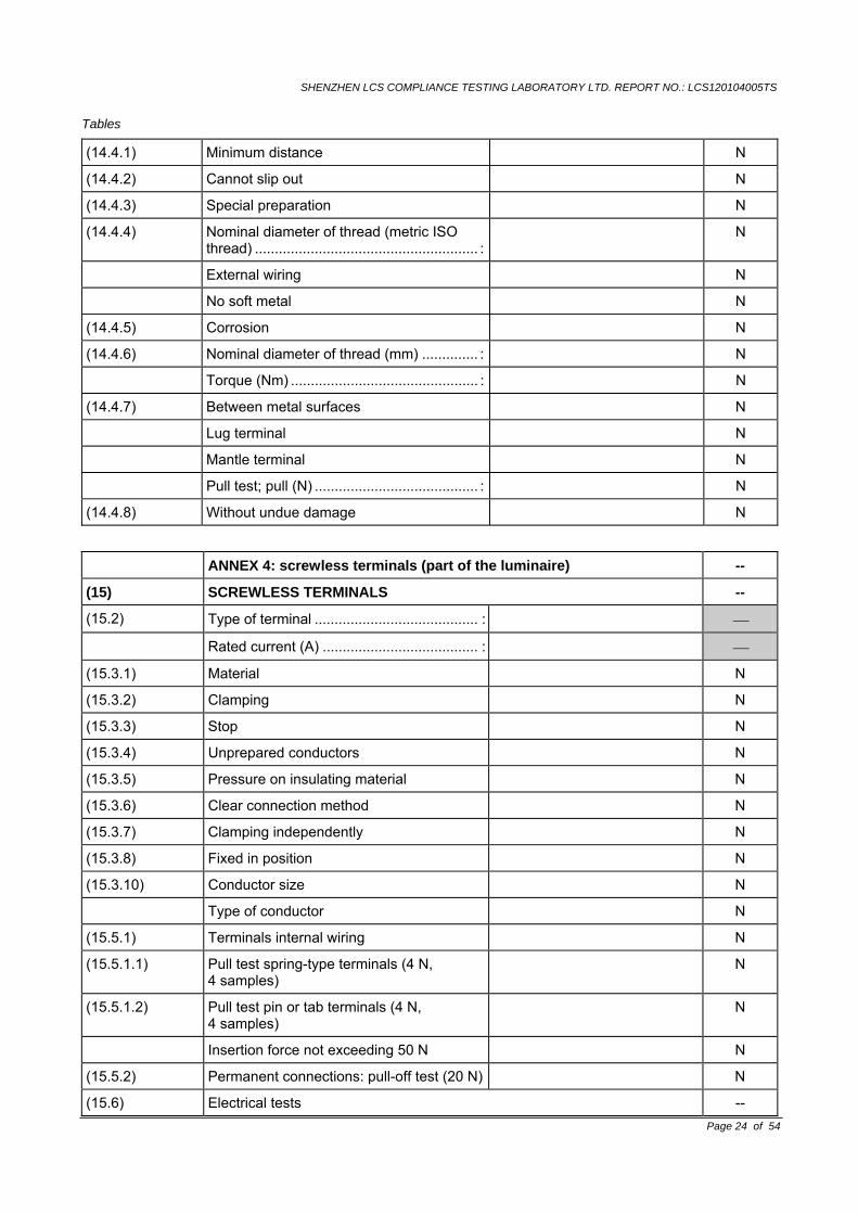
ANNEX 4: screwless terminals (part of the luminaire) --
(15) SCREWLESS TERMINALS --
(15.2) Type of terminal ......................................... : ⎯
Rated current (A) ....................................... : ⎯
(15.3.1) Material N
(15.3.2) Clamping N
(15.3.3) Stop N
(15.3.4) Unprepared conductors N
(15.3.5) Pressure on insulating material N
(15.3.6) Clear connection method N
(15.3.7) Clamping independently N
(15.3.8) Fixed in position N
(15.3.10) Conductor size N
Type of conductor N
(15.5.1) Terminals internal wiring N
(15.5.1.1) Pull test spring-type terminals (4 N, 4 samples)
N
(15.5.1.2) Pull test pin or tab terminals (4 N, 4 samples)
N
Insertion force not exceeding 50 N N
(15.5.2) Permanent connections: pull-off test (20 N) N
(15.6) Electrical tests --
SHENZHEN LCS COMPLIANCE TESTING LABORATORY LTD. REPORT NO.: LCS120104005TS
Tables
Page 25 of 54
Voltage drop (mV) after 1 h (4 samples).... : N
Voltage drop of two inseparable joints N
Number of cycles ....................................... : N
Voltage drop (mV) after 10th alt. 25th cycle (4 samples) ................................................ :
N
Voltage drop (mV) after 50th alt. 100th cycle (4 samples) ............................. :
N
After ageing, voltage drop (mV) after 10th alt. 25th cycle (4 samples) ......................... :
N
After ageing, voltage drop (mV) after 50th alt. 100th cycle (4 samples) ....................... :
N
(15.7) Terminals external wiring N
Terminal size and rating N
(15.8.1) Pull test spring-type terminals (4 samples); pull (N)
N
Pull test pin or tab terminals (4 samples); pull (N)
N
(15.9) Contact resistance test N
Voltage drop (mV) after 1 h N
terminal 1 2 3 4 5 6 7 8 9 10
voltage drop (mV)
Voltage drop of two inseparable joints
Voltage drop after 10th alt. 25th cycle
Max. allowed voltage drop (mV) ................ : ⎯
terminal 1 2 3 4 5 6 7 8 9 10
voltage drop (mV)
Voltage drop after 50th alt. 100th cycle
Max. allowed voltage drop (mV) ................ : ⎯
terminal 1 2 3 4 5 6 7 8 9 10
voltage drop (mV)
Continued ageing: voltage drop after 10th alt. 25th cycle
Max. allowed voltage drop (mV) ................ : ⎯
terminal 1 2 3 4 5 6 7 8 9 10
voltage drop (mV)
Continued ageing: voltage drop after 50th alt. 100th cycle
Max. allowed voltage drop (mV) ................ : ⎯
terminal 1 2 3 4 5 6 7 8 9 10
voltage drop (mV)
SHENZHEN LCS COMPLIANCE TESTING LABORATORY LTD. REPORT NO.: LCS120104005TS
Pictures
Page 26 of 54
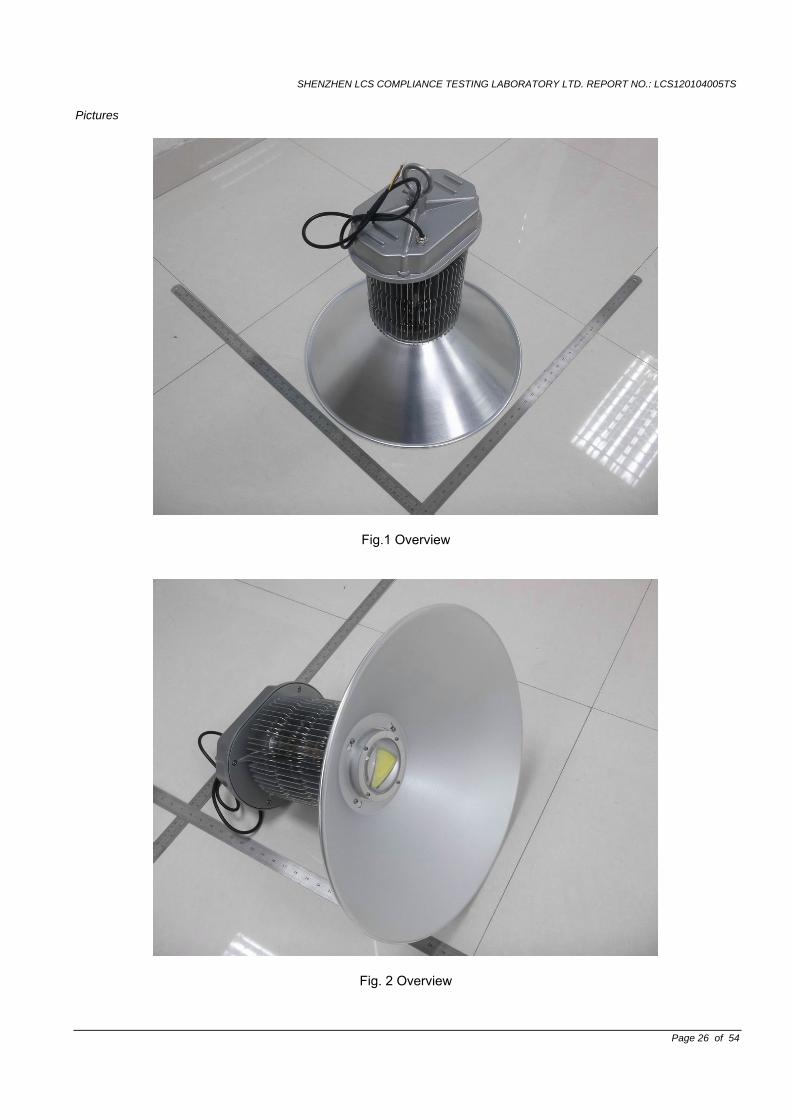
Fig.1 Overview
Fig. 2 Overview
SHENZHEN LCS COMPLIANCE TESTING LABORATORY LTD. REPORT NO.: LCS120104005TS
Pictures
Page 27 of 54
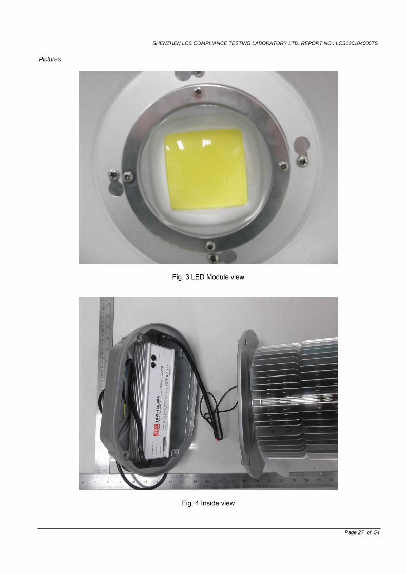
Fig. 3 LED Module view
Fig. 4 Inside view
SHENZHEN LCS COMPLIANCE TESTING LABORATORY LTD. REPORT NO.: LCS120104005TS
Pictures
Page 28 of 54
Fig. 5 LED driver view
SHENZHEN LCS COMPLIANCE TESTING LABORATORY LTD. REPORT NO.: LCS120104005TS
Page 29 of 54
Attachment No.1 TEST REPORT
EN 62471 Photobiological safety of lamps and lamp systems
Report reference No. ....................: See report EN 60598-2-1
Tested by(name + signature)........: See report EN 60598-2-1
Approved by(name +signature) ....: See report EN 60598-2-1
Date of issue ................................: See report EN 60598-2-1
Contents........................................: See report EN 60598-2-1
Testing laboratory
Name .............................................. : See report EN 60598-2-1
Address........................................... : See report EN 60598-2-1
Testing location ..........................: See report EN 60598-2-1
Client Name ............................................: See report EN 60598-2-1
Address .........................................: See report EN 60598-2-1
Manufacturer Name ............................................: See report EN 60598-2-1
Address .........................................: See report EN 60598-2-1
Test specification Standard........................................: EN 62471: 2008 Test procedure .............................: Compliance with EN 62471: 2008
Non-standard test method ...........: N.A.
Test item Description .................: See report EN 60598-2-1
Trademark ....................................: See report EN 60598-2-1
Model and/or type reference .........: See report EN 60598-2-1 Rating(s)........................................: See report EN 60598-2-1
SHENZHEN LCS COMPLIANCE TESTING LABORATORY LTD. REPORT NO.: LCS120104005TS
EN 62471
Clause Requirement - Test Result - Remark Verdict
Page 30 of 54
1 SCOPE P
More sections applicable .............................. Yes [√ ] No [ ] ⎯
4 EXPOSURE LIMITS P
4.1 General P
The exposure limits in this standard apply to continuous sources where the exposure duration is not less than 0,01 ms and not more than any 8-hour period, and should be used as guides in the control of exposure. The values should not be regarded as precisely defined lines between safe and unsafe levels.
P
detailed spectral data of a light source are generally required only if the luminance of the source exceeds 104 cd•m-2.
See clause 4.3 P
4.2 Specific factors involved in the determination and application of retinal exposure limits
N
4.2.1 Pupil diameter P
4.2.2 Angular subtense of source and measurement field-of-view
P
4.3 Hazard exposure limits P
4.3.1 Actinic UV hazard exposure limit for the skin and eye
LED light source N
The limits for exposure to ultraviolet radiation incident upon the unprotected skin or eye apply to exposure within any 8-hour period.
N
To protect against injury of the eye or skin from ultraviolet radiation exposure produced by a broadband source, the effective integrated spectral irradiance, Es, of the light source shall not exceed the levels defined by:
N
400
200( ) ( )Δ Δs UV
tE t E t S tλ λ λ λ• = • •∑∑ ,
J•m-2
N
The permissible time for exposure to ultraviolet radiation incident upon the unprotected eye or skin shall be computed by:
N
max
30
s
tE
= N
4.3.2 Near-UV hazard exposure limit for the eye N
SHENZHEN LCS COMPLIANCE TESTING LABORATORY LTD. REPORT NO.: LCS120104005TS
EN 62471
Clause Requirement - Test Result - Remark Verdict
Page 31 of 54
For the spectral region 315 nm to 400 nm (UV-A) the total radiant exposure to the eye shall not exceed 10000 J m-2 for exposure times less than 1000 s. For exposure times greater than 1000 s (approximately 16 minutes) the UV-A irradiance for the unprotected eye, EUVA, shall not exceed 10 W m-2.
N
400
315( ) Δ Δ 1000SUV
tE t E t tλ λ λ• = • • ≤∑∑ ,
J•m-2 ((t < 1000 s)
N
The permissible time for exposure to ultraviolet radiation incident upon the unprotected eye for times less than 1000 s, shall be computed by:
N
max
1000
UVA
tE
≤ S N
4.3.3 Retinal blue light hazard exposure limit P
To protect against retinal photochemical injury from chronic blue-light exposure, the integrated spectral radiance of the light source weighted against the blue-light hazard function, B(λ), i.e., the blue light weighted radiance, LB, shall not exceed the levels defined by:
P
700
( )300
( ) Δ Δ 1Bt
L t L t B tλ λλ λ• = • • • ≤∑∑ ,
J•m-2•sr-1
(for 410t s≤ )
N
700
( )300
Δ 100BL L Bλ λ λ= • • ≤∑ W•m-2•sr-1 For t>104S P
4.3.4 Retinal blue light hazard exposure limit - small source
P
Thus the spectral irradiance at the eye Eλ, weighted against the blue-light hazard function B(λ) (see Table 4.2) shall not exceed the levels defined by:
N
700
300( ) ( ) Δ Δ 100B
tE t E t B tλ λ λ λ• = • • • ≤∑∑ ,
(for t≥100s) N
SHENZHEN LCS COMPLIANCE TESTING LABORATORY LTD. REPORT NO.: LCS120104005TS
EN 62471
Clause Requirement - Test Result - Remark Verdict
Page 32 of 54
700
300
( ) Δ 1BE E Bλ λ λ= • • ≤∑
For t ≤100s N
4.3.5 Retinal thermal hazard exposure limit N
To protect against retinal thermal injury, the integrated spectral radiance of the light source, Lλ ,weighted by the burn hazard
weighting function ( )B λ (from Figure 4.2 and Table 4.2), i.e., the burn hazard weighted radiance, shall not exceed the levels defined by:
N
1400
0.25380
50000( ) ΔRL L Btλ λ λ
α= • • ≤
⋅∑ J•m-
2•sr-1
10us≤t≤10s N
4.3.6 Retinal thermal hazard exposure limit – weak visual stimulus
P
For an infrared heat lamp or any near-infrared source where a weak visual stimulus is inadequate to activate the aversion response, the near infrared (780 nm to 1400 nm) radiance, LIR, as viewed by the eye for exposure times greater than 10 s shall be limited to:
P
1400
780
6000( ) ΔIRL L Bλ λ λα
= • • ≤∑ J•m-2•sr-1t>10s P
4.3.7 Infrared radiation hazard exposure limits for the eye
N
To avoid thermal injury of the cornea and possible delayed effects upon the lens of the eye (cataractogenesis), ocular exposure to infrared radiation, EIR, over the wavelength range 780 nm to 3000 nm, for times less than 1000 s, shall not exceed:
N
30000.75
780Δ 1800IRE E tλ λ −= • ≤ ⋅∑ W•m-2
T≤1000s N
For times greater than 1000 s the limit becomes:
N
3000
780
Δ 100IRE Eλ λ= • ≤∑ W•m-2 T>1000s N
4.3.8 Thermal hazard exposure limit for the skin P
SHENZHEN LCS COMPLIANCE TESTING LABORATORY LTD. REPORT NO.: LCS120104005TS
EN 62471
Clause Requirement - Test Result - Remark Verdict
Page 33 of 54
Visible and infrared radiant exposure (380 nm to 3000 nm) of the skin shall be limited to:
P
30000.25
380( , ) Δ 20000H
tE t E t tλ λ λ⋅ = • ≤ ⋅∑∑
P
5 MEASUREMENT OF LAMPS AND LAMP SYSTEMS P
5.1 Measurement conditions P
Measurement conditions shall be reported as part of the evaluation against the exposure limits and the assignment of risk classification.
P
5.1.1 Lamp ageing (seasoning) ............................. P
Seasoning of lamps shall be done as stated in the appropriate IEC lamp standard.
P
5.1.2 Test environment .......................................... P
For specific test conditions, see the appropriate IEC lamp standard or in the absence of such standards, the appropriate national standards or manufacturer’s recommendations.
P
5.1.3 Extraneous radiation ..................................... N
Careful checks should be made to ensure that extraneous sources of radiation and reflections do not add significantly to the measurement results.
P
5.1.4 Lamp operation ............................................. P
Operation of the test lamp shall be provided in accordance with:
P
--the appropriate IEC lamp standard. P
--the lamp manufacturer’s recommendation P
5.1.5 Lamp system operation................................. P
The power source for operation of the test lamp shall be provided in accordance with
P
--the appropriate IEC standard. P
-- the lamp manufacturer’s recommendation
N
5.2 Measurement procedure P
5.2.1 Irradiance measurements ............................. P
minimum input aperture diameter of 7 mm N
maximum input aperture diameter of 50 mm
P
The measurement shall be made in that position of the beam giving the maximum reading.
P
SHENZHEN LCS COMPLIANCE TESTING LABORATORY LTD. REPORT NO.: LCS120104005TS
EN 62471
Clause Requirement - Test Result - Remark Verdict
Page 34 of 54
The measurement instrument is adequate calibrated
P
5.2.2 Radiance measurements .............................. P
5.2.2.1 Standard method........................................... P
The measurement made with an optical system
P
The instrument shall be calibrated to read in absolute incident radiant power per unit receiving area and per unit solid angle of acceptance averaged over the field of view (FOV) of the instrument.
P
5.2.2.2 Alternative method ........................................ P
Alternative to an imaging radiance set-up, an irradiance measurement set-up with a circular field stop placed at the source can be used to perform radiance measurements
5.2.3 Measurement of source size......................... P
The determination of a, the angle subtended ba a source, requires the determination of the 50% emission point of the source
0.188 P
5.2.4 Pulse width measurement for pulsed sources..........................................................
N
The determination of Δt, the nominal pulse duration of a source, requires the determination of the time during which the emission is > 50% of its peak value.
N
5.3 Analysis methods P
5.3.1 Weighting curve interpolations...................... P
The standardize interpolated values, use linear interpolation on the log of given values to obtion intermediate point at the wavelength internals de-sired.
See table 4.1 P
5.3.2 Calculations................................................... P
The calculation of source hazard values shall be performed by weighting the spectral scan by the appropriate function and calculating the total weighted energy.
P
5.3.3 Measurement uncertainty ............................. P
The quality of all measurement results must be quantified by an analysis of the uncertainty.
See annex C P
6 LAMP CLASSIFICATION P
SHENZHEN LCS COMPLIANCE TESTING LABORATORY LTD. REPORT NO.: LCS120104005TS
EN 62471
Clause Requirement - Test Result - Remark Verdict
Page 35 of 54
For the purposes of this standard it was decided that the values shall be reported as follows:
N
for lamps intended for general lighting service (GLS), the hazard values shall be reported as either irradiance or radiance values at a distance which produces an illuminance of 500 lux, but not at a distance less than 200 mm;
P
for all other light sources, including pulsed lamp sources, the hazard values shall be reported at a distance of 200 mm.
N
6.1 Continuous wave lamps Class I Laser Product P
6.1.1 Exempt group P
the exempt group are lamps, which does not pose any photobiological. This requirement is met by any lamp that does not pose
P
--an actinic ultraviolet hazard (Es) within 8-hours exposure (30000 s), nor
N
--a near-UV hazard (EUVA) within 1000 s, (about 16 min) nor
N
--a retinal blue-light hazard (LB) within 10000 s (about 2,8 h), nor
P
--a retinal thermal hazard (LR) within 10 s, nor
P
--an infrared radiation hazard for the eye (EIR) within 1000 s.
N
6.1.2 Risk Group 1 (Low-Risk) N
In this group are lamps, which exceeds the limited for the except group but that does not pose:
N
--an actinic ultraviolet hazard (Es) within 10000 s, nor
N
--a near ultraviolet hazard (EUVA) within 300 s, nor
N
--a retinal blue-light hazard (LB) within 100 s, nor
N
--a retinal thermal hazard (LR) within 10 s, nor
N
--an infrared radiation hazard for the eye (EIR) within 100 s.
N
lamps that emit infrared radiation without a strong visual stimulus (i.e., less than 10 cd•m-2) and do not pose a near-infrared retinal hazard (LIR), within 100 s are in Risk Group 1 (Low-Risk).
N
6.1.3 Risk Group 2 (Moderate-Risk) N
This requirement is met by any lamp that exceeds the limits for risk Group 1, but that does not pose:
N
SHENZHEN LCS COMPLIANCE TESTING LABORATORY LTD. REPORT NO.: LCS120104005TS
EN 62471
Clause Requirement - Test Result - Remark Verdict
Page 36 of 54
--an actinic ultraviolet hazard (Es) within 1000 s exposure, nor
N
--a near ultraviolet hazard (EUVA) within 100 s, nor
N
--a retinal blue-light hazard (LB) within 0,25 s (aversion response), nor
N
--a retinal thermal hazard (LR) within 0,25 s (aversion response), nor
N
--an infrared radiation hazard for the eye (EIR) within 10 s.
N
lamps that emit infrared radiation without a strong visual stimulus (i.e., less than 10 cd•m-2) and do not pose a near infrared retinal hazard (LIR) within 10 s are in Risk Group 2 (Moderate-Risk).
N
6.1.4 Risk Group 3 (High-Risk) N
Lamps which exceed the limits for Risk Group 2 (Moderate-Risk) are in Risk Group3 (High-Risk).
N
6.2 Pulsed lamps N
Pulsed lamp criteria shall apply to a single pulse and to any group of pulses within 0 25 second
N
A pulsed lamp shall be evaluated at the highest nominal energy loading as specified by the manufacturer
N
The risk group determination of the lamp being tested shall be made as follows:
N
-- A lamp that exceeds the exposure limit shall be classified as belonging to Risk Group 3 (High-Risk).
N
-- For single pulsed lamps, a lamp whose weighted radiant exposure or weighted radiance dose is below the EL shall be classified as belonging to the Exempt Group.
N
-- For repetitively pulsed lamps, a lamp whose weighted radiant exposure or weighted radiance dose is below the EL, shall be evaluated using the Continuous wave risk criteria discussed in clause 6.1, using time averaged values of the pulsed emission.
N
ANNEX A SUMMARY OF BIOLOGICAL EFFECTS --
Bioeffect datasheet #1: Infrared cataract N
A.1 Bioeffect: INFRARED CATARACT also known as "industrial heat cataract, "furnaceman's cataract", or "glassblower's cataract".
N
SHENZHEN LCS COMPLIANCE TESTING LABORATORY LTD. REPORT NO.: LCS120104005TS
EN 62471
Clause Requirement - Test Result - Remark Verdict
Page 37 of 54
A.1.1 Organ/Site: Eye/Crystalline Lens. N
A.1.2 Spectral range: 700 nm to 1400 nm and possibly to 3000 nm.
N
A.1.3 Peak of action spectrum: Not known; probably between 900-1000 nm.
N
A.1.4 State of knowledge: Limited threshold data available for acute cataract for rabbit at 1064 nm (Wolbarsht, 1992) and lR-A region (Pitts and Cullen, 1981); no data for man. Degree of additivity and action spectrum unknown. Good epidemiological evidence (Lydahl, 1984).
N
A.1.5 Time course: Noticeable clouding of the lens generally following years of chronic high-level exposure, the elapsed time depending upon how much difference between exposure and threshold, heavy exposures producing reaction in shortest time.
N
A.1.6 Mechanism: Generally presumed to be thermal, although recent evidence suggests possible photochemical reaction - details not understood. The lens may be heated either from direct irradiation (Vogt, 1919) or by conductive heating from the heated iris (Goldman, 1983).
N
A.1.7 Symptoms: Clouding of vision. N
A.1.8 Needed information: Action spectrum, if existent, for acute and for effects of concomitant ultraviolet radiation exposure; additivity of multiple exposures, and the possibility of delayed effects from recurrent exposures.
N
A.1.9 Experience with lamps: Accidental injury is not known, even from exposure to heat lamps. Limited population exposed.
N
A.1.10 Key references N
Bioeffect datasheet #2 --
A.2 Bioeffect P
A.2.1 Organ/Site P
A.2.2 Spectral range P
A.2.3 Peak of action spectrum P
A.2.4 State of knowledge P
A.2.5 Time course P
A.2.6 Mechanism P
A.2.7 Symptoms P
SHENZHEN LCS COMPLIANCE TESTING LABORATORY LTD. REPORT NO.: LCS120104005TS
EN 62471
Clause Requirement - Test Result - Remark Verdict
Page 38 of 54
A.2.8 Needed information P
A.2.9 Experience with lamps P
A.2.10 Key references P
Bioeffect datasheet #3 --
A.3 Bioeffect N
A.3.1 Organ/Site N
A.3.2 Spectral range N
A.3.3 Peak of action spectrum N
A.3.4 State of knowledge N
A.3.5 Time course N
A.3.6 Mechanism N
A.3.7 Symptoms N
A.3.8 Needed information N
A.3.9 Experience with lamps N
A.3.10 Key references N
Bioeffect datasheet #4 --
A.4 Bioeffect N
A.4.1 Organ/Site N
A.4.2 Spectral range N
A.4.3 Peak of action spectrum N
A.4.4 State of knowledge N
A.4.5 Time course N
A.4.6 Mechanism N
A.4.7 Symptoms N
A.3.8 Needed information N
A.4.9 Experience with lamps N
A.4.10 Key references N
Bioeffect datasheet #5 --
A.5 Bioeffect N
A.5.1 Organ/Site N
A.5.2 Spectral range N
A.5.3 Peak of action spectrum N
A.5.4 State of knowledge N
A.5.5 Time course N
A.5.6 Mechanism N
A.5.7 Symptoms N
A.5.8 Needed information N
SHENZHEN LCS COMPLIANCE TESTING LABORATORY LTD. REPORT NO.: LCS120104005TS
EN 62471
Clause Requirement - Test Result - Remark Verdict
Page 39 of 54
A.5.9 Experience with lamps N
A.5.10 Key references N
ANNEX B MEASUREMENT METHOD N
B.1 Instrumentation N
B.1.1 Double monochromator: Recommended instrument
N
B.1.2 Broadband detectors N
B.2 Instrument limitations N
B.2.1 Noise equivalent irradiance N
B.2.2 Instrument spectral response N
B.2.3 Wavelength accuracy N
B.2.4 Stray radiant power N
B.2.5 Input optics for spectral irradiance measurements: Recommendation
N
B.2.6 Linearity N
B.3 Calibration sources N
ANNEX C UNCERTAINTY ANALYSIS P
ANNEX D GENERAL REFERENCES P
ANNEX ZA Normative references to international
publications with their corresponding European publications
N
ANNEX ZB EXPOSURE LIMITS (EL’S) See ANNEX ZB above P
SHENZHEN LCS COMPLIANCE TESTING LABORATORY LTD. REPORT NO.: LCS120104005TS Tables
Page 40 of 54
Table 4.1 Spectral weighting function for assessing ultraviolet hazards for skin and eye.
P
Wavelength1 λ, nm
UV hazard function SUV(λ)
Wavelength λ, nm
UV hazard function SUV(λ)
200 0,030 313* 0,006
205 0,051 315 0,003
210 0,075 316 0,0024
215 0,095 317 0,0020
220 0,120 318 0,0016
225 0,150 319 0,0012
230 0,190 320 0,0010
235 0,240 322 0,00067
240 0,300 323 0,00054
245 0,360 325 0,00050
250 0,430 328 0,00044
254* 0,500 330 0,00041
255 0,520 333* 0,00037
260 0,650 335 0,00034
265 0,810 340 0,00028
270 1,000 345 0,00024
275 0,960 350 0,00020
280 0,960 350 0,00020
285 0,880 355 0,00016
290 0,770 360 0,00013
295 0,540 370 0,00009
297* 0,460 375 0,000077
300 0,300 380 0,000064
303* 0,120 385 0,000053
305 0,060 390 0,000044
308 0,026 395 0,000036
310 0,015 400 0,000030 1 Wavelengths chosen are representative: other values should be obtained by logarithmic interpolation at intermediate wavelengths. * Emission lines of a mercury discharge spectrum.
SHENZHEN LCS COMPLIANCE TESTING LABORATORY LTD. REPORT NO.: LCS120104005TS Tables
Page 41 of 54
Table 4.2 Spectral weighting functions for assessing retinal hazards from broadband optical sources.
P
Wavelength nm
Blue-light hazard function B(λ)
Burn hazard function R(λ)
300 0,01
305 0,01
310 0,01
315 0,01
320 0,01
325 0,01
330 0,01
335 0,01
340 0,01
345 0,01
350 0,01
355 0,01
360 0,01
365 0,01
370 0,01
375 0,01 380 0,01 0,1 385 0,013 0,13
390 0,025 0,25
395 0,05 0,5
400 0,10 1,0
405 0,20 2,0
410 0,40 4,0
415 0,80 8,0
420 0,90 9,0
425 0,95 9,5
430 0,98 9,8
435 1,00 10,0
440 1,00 10,0
445 0,97 9,7
450 0,94 9,4
455 0,90 9,0
460 0,80 8,0
465 0,70 7,0
470 0,62 6,2
475 0,55 5,5
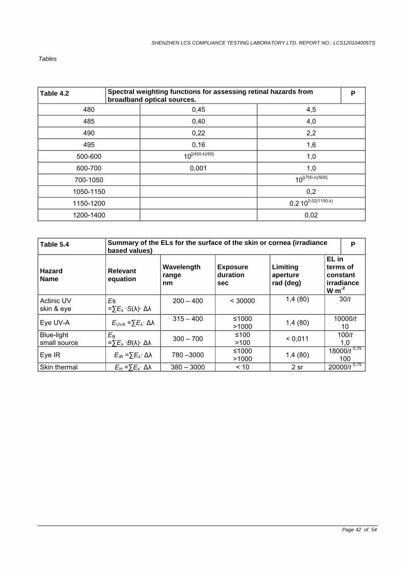
SHENZHEN LCS COMPLIANCE TESTING LABORATORY LTD. REPORT NO.: LCS120104005TS Tables
Page 42 of 54
Table 4.2 Spectral weighting functions for assessing retinal hazards from broadband optical sources.
P
480 0,45 4,5 485 0,40 4,0 490 0,22 2,2 495 0,16 1,6
500-600 10[(450-λ)/50] 1,0
600-700 0,001 1,0
700-1050 10[(700-λ)/500]
1050-1150 0,2
1150-1200 0,2.100,02(1150-λ)
1200-1400 0,02
Table 5.4 Summary of the ELs for the surface of the skin or cornea (irradiance based values)
P
Hazard Name
Relevant equation
Wavelength range nm
Exposure duration sec
Limiting aperture rad (deg)
EL in terms of constant irradianceW·m-2
Actinic UV skin & eye
Es =∑Eλ ·S(λ)· Δλ
200 – 400
< 30000
1,4 (80)
30/t
Eye UV-A EUVA =∑Eλ· Δλ 315 – 400
≤1000 >1000 1,4 (80) 10000/t
10 Blue-light small source
EB =∑Eλ ·B(λ)· Δλ 300 – 700 ≤100
>100 < 0,011 100/t 1,0
Eye IR EIR =∑Eλ· Δλ 780 –3000 ≤1000 >1000 1,4 (80) 18000/t 0,75
100 Skin thermal EH =∑Eλ· Δλ 380 – 3000 < 10 2 sr 20000/t 0,75
SHENZHEN LCS COMPLIANCE TESTING LABORATORY LTD. REPORT NO.: LCS120104005TS Tables
Page 43 of 54
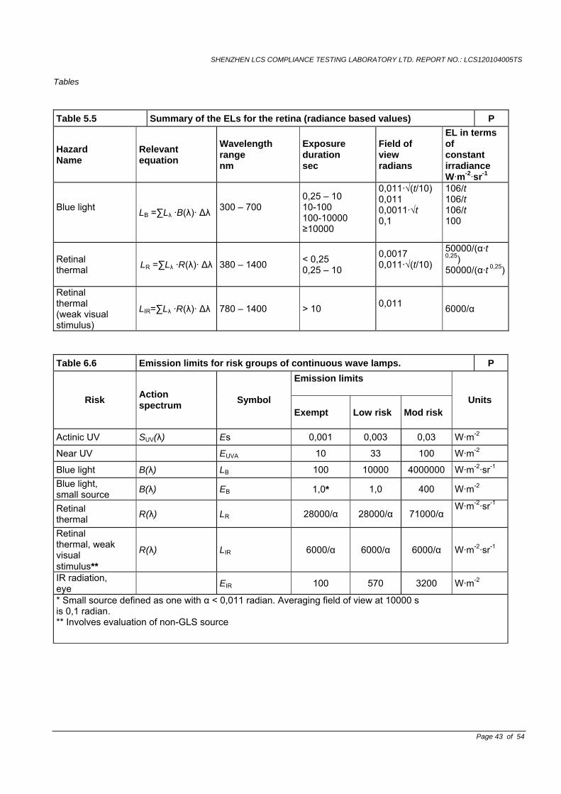
Table 5.5 Summary of the ELs for the retina (radiance based values) P
Hazard Name
Relevant equation
Wavelength range nm
Exposure duration sec
Field of view radians
EL in terms of constant irradiance W·m-2·sr-1
Blue light LB =∑Lλ ·B(λ)· Δλ 300 – 700
0,25 – 10 10-100 100-10000 ≥10000
0,011·√(t/10) 0,011 0,0011·√t 0,1
106/t 106/t 106/t 100
Retinal thermal LR =∑Lλ ·R(λ)· Δλ 380 – 1400 < 0,25
0,25 – 10
0,0017 0,011·√(t/10)
50000/(α·t 0,25) 50000/(α·t 0,25)
Retinal thermal (weak visual stimulus)
LIR=∑Lλ ·R(λ)· Δλ 780 – 1400 > 10 0,011 6000/α
Table 6.6 Emission limits for risk groups of continuous wave lamps. P Emission limits
Risk Action spectrum Symbol
Exempt Low risk Mod risk Units
Actinic UV SUV(λ) Es 0,001 0,003 0,03 W·m-2
Near UV EUVA 10 33 100 W·m-2
Blue light B(λ) LB 100 10000 4000000 W·m-2·sr-1 Blue light, small source B(λ) EB 1,0* 1,0 400 W·m-2
Retinal thermal R(λ) LR 28000/α 28000/α 71000/α
W·m-2·sr-1
Retinal thermal, weak visual stimulus**
R(λ) LIR 6000/α 6000/α 6000/α W·m-2·sr-1
IR radiation, eye EIR 100 570 3200 W·m-2
* Small source defined as one with α < 0,011 radian. Averaging field of view at 10000 s is 0,1 radian. ** Involves evaluation of non-GLS source
SHENZHEN LCS COMPLIANCE TESTING LABORATORY LTD. REPORT NO.: LCS120104005TS
Page 44 of 54
Attachment No.2 TEST REPORT
EN 62031 LED modules for general lighting - Safety specifications
Report reference No. ..................: See report EN 60598-2-1
Tested by(name + signature)........: See report EN 60598-2-1
Approved by(name +signature) ....: See report EN 60598-2-1
Date of issue ................................: See report EN 60598-2-1
Contents........................................: See report EN 60598-2-1
Testing laboratory
Name .............................................. : See report EN 60598-2-1
Address........................................... : See report EN 60598-2-1
Testing location ............................: See report EN 60598-2-1 Client
Name ............................................: See report EN 60598-2-1
Address .........................................: See report EN 60598-2-1
Manufacturer
Name ............................................: See report EN 60598-2-1
Address .........................................: See report EN 60598-2-1
Test specification Standard........................................: EN 62031: 2008 Test procedure .............................: Compliance with EN 62031: 2008
Non-standard test method ...........: N.A.
Test item Description .................: See report EN 60598-2-1
Trademark ....................................: See report EN 60598-2-1 Model and/or type reference .........: See report EN 60598-2-1 Rating(s)........................................: See report EN 60598-2-1
SHENZHEN LCS COMPLIANCE TESTING LABORATORY LTD. REPORT NO.: LCS120104005TS
EN 62031
Clause Requirement - Test Result - Remark Verdict
Page 45 of 54
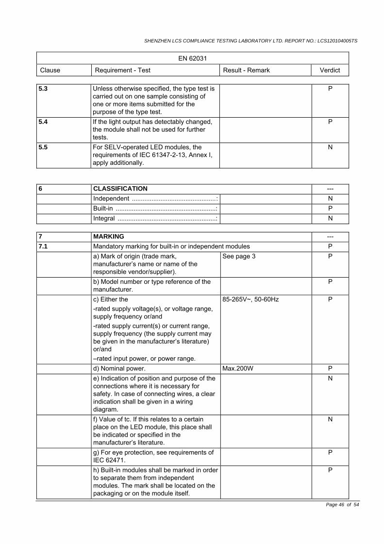
4 General requirements --- 4.1 Modules shall be so designed and
constructed that in normal use (see manufacturer’s instruction) they operate without danger to the user or surroundings:
P
4.2 For LED modules, all electrical measurements, unless otherwise specified, shall be carried out at voltage limits (min/max), current limits (min/max) or power limits (min/max) and minimum frequency, in a draught-free room at the temperature limits of the allowed range specified by the manufacturer. Unless the manufacturer indicates the most critical combination, all combinations (min/max) of voltage/current/power and temperature shall be tested.
P
4.3 For self-ballasted LED modules, the electrical measurements shall be carried out at the tolerance limit values of the marked supply voltage.
P
4.4 Integral modules not having their own enclosure shall be treated as integral components of luminaires as defined in IEC 60598-1, Clause 0.5. They shall be tested assembled in the luminaire, and as far as applicable with the present standard.
Built-in modules N
4.5 Independent modules shall comply, in addition to this standard, with the requirements of relevant clauses of IEC 60598-1, where these requirements are not already covered in this standard.
N
4.6 If the module is a factory sealed unit, it shall not be opened for any tests. In the case of doubt based on the inspection of the module and the examination of the circuit diagram, and in agreement with the manufacturer or responsible vendor, such specially prepared modules shall be submitted for testing so that a fault condition can be simulated.
Sealed P
5 General test requirements --- 5.1 Tests according to this standard are type
tests P
5.2 Unless otherwise specified, the tests are carried out at an ambient temperature of 10 to 30
P
SHENZHEN LCS COMPLIANCE TESTING LABORATORY LTD. REPORT NO.: LCS120104005TS
EN 62031
Clause Requirement - Test Result - Remark Verdict
Page 46 of 54
5.3 Unless otherwise specified, the type test is carried out on one sample consisting of one or more items submitted for the purpose of the type test.
P
5.4 If the light output has detectably changed, the module shall not be used for further tests.
P
5.5 For SELV-operated LED modules, the requirements of IEC 61347-2-13, Annex I, apply additionally.
N
6 CLASSIFICATION --- Independent ...............................................: N Built-in ........................................................: P Integral .......................................................: N
7 MARKING --- 7.1 Mandatory marking for built-in or independent modules P a) Mark of origin (trade mark,
manufacturer’s name or name of the responsible vendor/supplier).
See page 3 P
b) Model number or type reference of the manufacturer.
P
c) Either the -rated supply voltage(s), or voltage range, supply frequency or/and -rated supply current(s) or current range, supply frequency (the supply current may be given in the manufacturer’s literature) or/and –rated input power, or power range.
85-265V~, 50-60Hz P
d) Nominal power. Max.200W P e) Indication of position and purpose of the
connections where it is necessary for safety. In case of connecting wires, a clear indication shall be given in a wiring diagram.
N
f) Value of tc. If this relates to a certain place on the LED module, this place shall be indicated or specified in the manufacturer’s literature.
N
g) For eye protection, see requirements of IEC 62471.
P
h) Built-in modules shall be marked in order to separate them from independent modules. The mark shall be located on the packaging or on the module itself.
P
SHENZHEN LCS COMPLIANCE TESTING LABORATORY LTD. REPORT NO.: LCS120104005TS
EN 62031
Clause Requirement - Test Result - Remark Verdict
Page 47 of 54
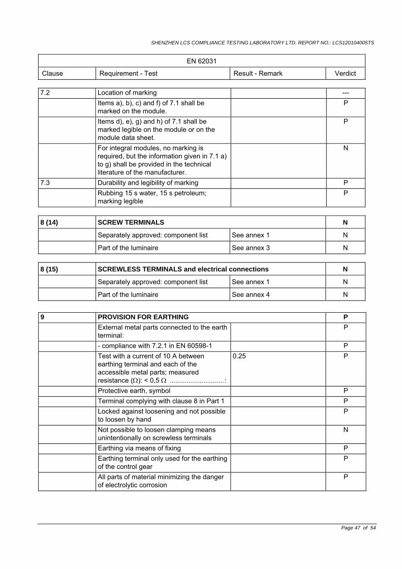
7.2 Location of marking --- Items a), b), c) and f) of 7.1 shall be
marked on the module. P
Items d), e), g) and h) of 7.1 shall be marked legible on the module or on the module data sheet.
P
For integral modules, no marking is required, but the information given in 7.1 a) to g) shall be provided in the technical literature of the manufacturer.
N
7.3 Durability and legibility of marking P Rubbing 15 s water, 15 s petroleum;
marking legible P
8 (14) SCREW TERMINALS N
Separately approved: component list See annex 1 N
Part of the luminaire See annex 3 N 8 (15) SCREWLESS TERMINALS and electrical connections N
Separately approved: component list See annex 1 N
Part of the luminaire See annex 4 N
9 PROVISION FOR EARTHING P External metal parts connected to the earth
terminal: P
- compliance with 7.2.1 in EN 60598-1 P Test with a current of 10 A between
earthing terminal and each of the accessible metal parts; measured resistance (Ω): < 0,5 Ω ............................. :
0.25 P
Protective earth, symbol P Terminal complying with clause 8 in Part 1 P Locked against loosening and not possible
to loosen by hand P
Not possible to loosen clamping means unintentionally on screwless terminals
N
Earthing via means of fixing P Earthing terminal only used for the earthing
of the control gear P
All parts of material minimizing the danger of electrolytic corrosion
P
SHENZHEN LCS COMPLIANCE TESTING LABORATORY LTD. REPORT NO.: LCS120104005TS
EN 62031
Clause Requirement - Test Result - Remark Verdict
Page 48 of 54
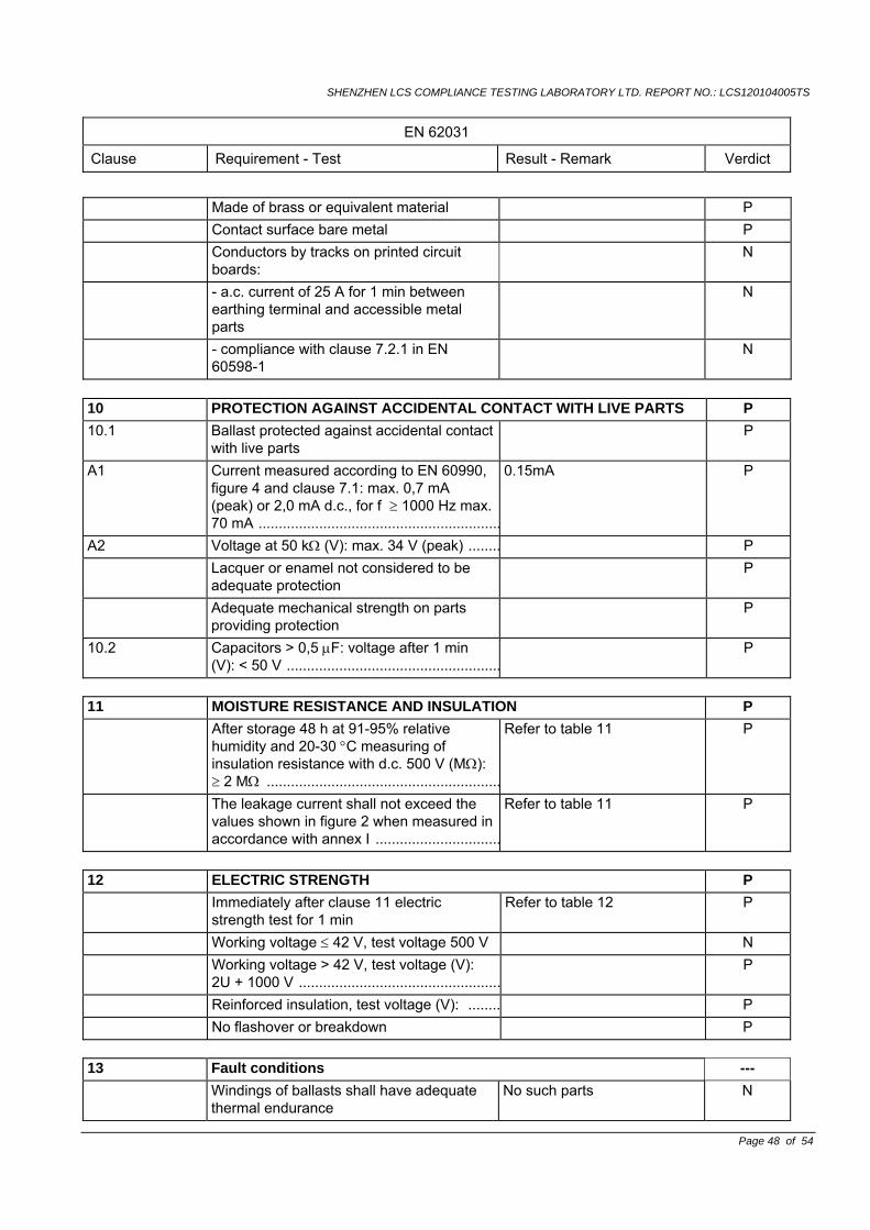
10 PROTECTION AGAINST ACCIDENTAL CONTACT WITH LIVE PARTS P 10.1 Ballast protected against accidental contact
with live parts P
A1 Current measured according to EN 60990, figure 4 and clause 7.1: max. 0,7 mA (peak) or 2,0 mA d.c., for f ≥ 1000 Hz max. 70 mA ............................................................
0.15mA P
A2 Voltage at 50 kΩ (V): max. 34 V (peak) ........ P Lacquer or enamel not considered to be
adequate protection P
Adequate mechanical strength on parts providing protection
P
10.2 Capacitors > 0,5 μF: voltage after 1 min (V): < 50 V .....................................................
P
11 MOISTURE RESISTANCE AND INSULATION P After storage 48 h at 91-95% relative
humidity and 20-30 °C measuring of insulation resistance with d.c. 500 V (MΩ): ≥ 2 MΩ ..........................................................
Refer to table 11 P
The leakage current shall not exceed the values shown in figure 2 when measured in accordance with annex I ...............................
Refer to table 11 P
12 ELECTRIC STRENGTH P Immediately after clause 11 electric
strength test for 1 min Refer to table 12 P
Working voltage ≤ 42 V, test voltage 500 V N Working voltage > 42 V, test voltage (V):
2U + 1000 V .................................................. P
Reinforced insulation, test voltage (V): ........ P No flashover or breakdown P
13 Fault conditions --- Windings of ballasts shall have adequate
thermal endurance No such parts N
Made of brass or equivalent material P Contact surface bare metal P Conductors by tracks on printed circuit
boards: N
- a.c. current of 25 A for 1 min between earthing terminal and accessible metal parts
N
- compliance with clause 7.2.1 in EN 60598-1
N
SHENZHEN LCS COMPLIANCE TESTING LABORATORY LTD. REPORT NO.: LCS120104005TS
EN 62031
Clause Requirement - Test Result - Remark Verdict
Page 49 of 54
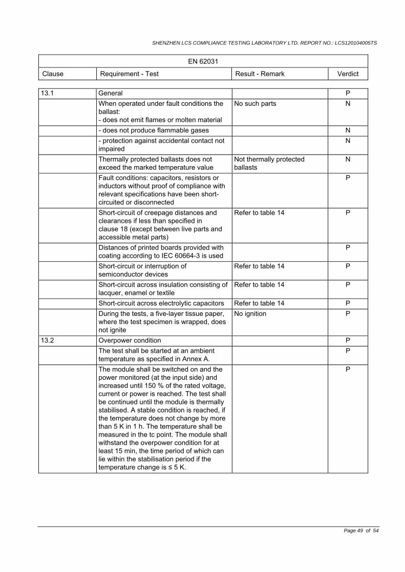
13.1 General P When operated under fault conditions the
ballast: - does not emit flames or molten material
No such parts N
- does not produce flammable gases N - protection against accidental contact not
impaired N
Thermally protected ballasts does not exceed the marked temperature value
Not thermally protected ballasts
N
Fault conditions: capacitors, resistors or inductors without proof of compliance with relevant specifications have been short-circuited or disconnected
P
Short-circuit of creepage distances and clearances if less than specified in clause 18 (except between live parts and accessible metal parts)
Refer to table 14 P
Distances of printed boards provided with coating according to IEC 60664-3 is used
P
Short-circuit or interruption of semiconductor devices
Refer to table 14 P
Short-circuit across insulation consisting of lacquer, enamel or textile
Refer to table 14 P
Short-circuit across electrolytic capacitors Refer to table 14 P During the tests, a five-layer tissue paper,
where the test specimen is wrapped, does not ignite
No ignition P
13.2 Overpower condition P The test shall be started at an ambient
temperature as specified in Annex A. P
The module shall be switched on and the power monitored (at the input side) and increased until 150 % of the rated voltage, current or power is reached. The test shall be continued until the module is thermally stabilised. A stable condition is reached, if the temperature does not change by more than 5 K in 1 h. The temperature shall be measured in the tc point. The module shall withstand the overpower condition for at least 15 min, the time period of which can lie within the stabilisation period if the temperature change is ≤ 5 K.
P
SHENZHEN LCS COMPLIANCE TESTING LABORATORY LTD. REPORT NO.: LCS120104005TS
EN 62031
Clause Requirement - Test Result - Remark Verdict
Page 50 of 54
If the module contains an automatic protective device or circuit which limits the power, it is subjected to a 15 min operation at this limit. If the device or circuit effectively limits the power over this period, the module has passed the test, provided the compliance (4.1 and last paragraph of 13.2) is fulfilled.
N
After finalising the overpower mode, the module is operated under normal conditions until thermally being stable.
P
A module fails safe if no fire, smoke or flammable gas is produced and if the 15 min overpower condition has been withstood. To check whether molten material might present a safety hazard, a tissue paper, as specified in 4.187 of ISO 4046-4, spread below the module shall not ignite.
N
15 Construction P Wood, cotton, silk, paper and similar
fibrous material shall not be used as insulation.
P
16 Creepage distances and clearances P Working voltage (V) ...................................: 85-265V~ P Voltage form Sinusoidal [ √ ]
Non-sinusoidal [ ] P
PTI < 600 [ √ ] > 600 [ ] P Impulse withstand category (normal
category II) (category III annex U) Normal category II P
Rated pulse voltage (kV) ...........................: N (1) Current-carrying parts of different
polarity: cr (mm); cl (mm) ...........................: See report EN 60598-2-1 P
(2) Current-carrying parts and accessible parts: cr (mm); cl (mm) .................: See report EN 60598-2-1 P
(3) Parts becoming live due to breakdown of basic insulation and metal parts: cr (mm); cl (mm) ............................................:
N
(4) Outer surface of cable where it is clamp and metal parts: cr (mm); cl (mm) .............:
N
(5)not used N (6) Current-carrying parts and supporting
surface: cr (mm); cl (mm) ...........................:See report EN 60598-2-1 P
17 SCREWS, CURRENT-CARRYING PARTS AND CONNECTIONS P 17 (4.11) Electrical connections P
SHENZHEN LCS COMPLIANCE TESTING LABORATORY LTD. REPORT NO.: LCS120104005TS
EN 62031
Clause Requirement - Test Result - Remark Verdict
Page 51 of 54
17(4.11.1) Contact pressure No pressure transmitted to the insulating material
P
17 (4.11.2) Screws: P - Self-tapping screws P - thread-cutting screws N 17 (4.11.3) Screw locking: P - spring washer P - rivets No rivet provided N 17 (4.11.4) Material of current-carrying parts > 50% copper P 17 (4.11.5) No contact to wood or mounting surface No wood P 17 (4.11.6) Electro-mechanical contact systems No such construction N 17 (4.12) Mechanical connections and glands P 17 (4.12.1) Screw not made of soft metal P Screws of insulating material N Torque test: torque (Nm); part ………....... 1.2Nm P Torque test: torque (Nm); part ………......... N Torque test: torque (Nm); part ………........ N 17 (4.12.2) Screw with diameter < 3 mm screw into
metal N
17 (4.12.4) Locked connections: N - fixed arms; torque (Nm) ...........................: N - lampholder; torque (Nm) .........................: N - push-button switches; torque (Nm) .........: No such switches N 1.6 (4.12.5) Screwed glands; force (N) : N
18 RESISTANCE TO HEAT, FIRE AND TRACKING --- 18.1 Parts of insulating material retaining live parts in position, ball-pressure test: N - part; test temperature (°C) .......................... N 18.2 Printed boards in accordance with
IEC 60249-1, 4.3 N
18.3 External parts of insulating material preventing electric shock glow-wire test 650 °C
N
18.4 Parts of insulating material retaining live parts in position, needle-flame test 10 s:
N
- flame extinguished within 30 s N - no flaming drops igniting tissue paper N 18.5 Tracking test Ordinary N
19 RESISTANCE TO CORROSION --- Rust protection: P - 10% solution of ammonium chloride in
water N
SHENZHEN LCS COMPLIANCE TESTING LABORATORY LTD. REPORT NO.: LCS120104005TS
EN 62031
Clause Requirement - Test Result - Remark Verdict
Page 52 of 54
- adequate varnish on the outer surface P
SHENZHEN LCS COMPLIANCE TESTING LABORATORY LTD. REPORT NO.: LCS120104005TS
Tables
Page 53 of 54
Table 11(a) Humidity test P
Temperature Relative Humidity Duration Breakdown (Y/N) Test condition:
25°C 93% 48 hours N Test points
Between To Measured insulation Limited insulation
Line & neutral Enclosure >100MΩ 2MΩ Table 11(b) Touch current measurement (mA) P
Condition Normal Reverse
Model No. ON OFF ON OFF
KPT-HBL1*200WA4 0.15 <0.15 0.5 <0.15
Table 12 Electric strength P
Test points
Between To
Test voltage Results
Line & neutral Enclosure 1530Vac No breakdown 13 TABLE: tests of fault conditions P
Part Simulated fault Test result Hazard CE2 s-c Resistor fuse opened, no dangerous No
RP1 s-c Resistor fuse opened, no dangerous No
Co1 s-c Resistor fuse opened, no dangerous No
C4 s-c Resistor fuse opened, no dangerous No 16 TABLE: creepage distances and clearances P
Minimum distances for a.c. (50/60 Hz) sinusoidal voltages P
RMS working voltage (V) not exceeding 50 150 250 500 750 1000
1 minimum distances between live parts of different polarity. Specify the value measured.
2 minimum distances between live parts and accessible parts which are permanently fixed to the ballast, including screws or devices for fixing covers or fixing the ballast to its support. Specify the value measured.
- required creepage distances (mm), insulation PTI ≥ 600
0,6 1,4 1,7 3 4 5,5
- required creepage distances (mm), insulation PTI < 600
1,2 1,6 2,5 5 8 10
- required clearances (mm) 0,2 1,4 1,7 3 4 5,5
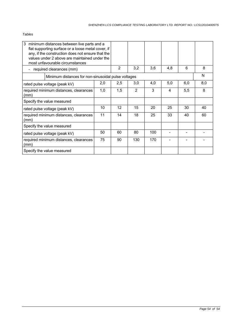
SHENZHEN LCS COMPLIANCE TESTING LABORATORY LTD. REPORT NO.: LCS120104005TS
Tables
Page 54 of 54
3 minimum distances between live parts and a flat supporting surface or a loose metal cover, if any, if the construction does not ensure that the values under 2 above are maintained under the most unfavourable circumstances
- required clearances (mm) 2 3,2 3,6 4,8 6 8
Minimum distances for non-sinusoidal pulse voltages N
rated pulse voltage (peak kV) 2,0 2,5 3,0 4,0 5,0 6,0 8,0
required minimum distances, clearances (mm)
1,0 1,5 2 3 4 5,5 8
Specify the value measured
rated pulse voltage (peak kV) 10 12 15 20 25 30 40
required minimum distances, clearances (mm)
11 14 18 25 33 40 60
Specify the value measured
rated pulse voltage (peak kV) 50 60 80 100 - - -
required minimum distances, clearances (mm)
75 90 130 170 - - -
Specify the value measured


![LED INTERIOR LUMINAIRE 2015Y [ V01 ]doc.diytrade.com/docdvr/503489/43212460/1427449177.pdf · - 1 - sales@gtegroupltd.com led interior luminaire 2015y [ v01 ] flush ceiling panel](https://img.pdfslide.us/doc/110x75/60203fa2eeb3f136720d0408/led-interior-luminaire-2015y-v01-doc-1-salesgtegroupltdcom-led-interior.jpg)
![Welcome [doc.diytrade.com] · 2017. 7. 21. · Welcome. CCT DIMMING Applications: O˜ces / Classrooms / Malls / Hotel / Lobbies / Back of house / Restaurants / Bus Stations / Medical](https://img.pdfslide.us/doc/110x75/60b8f7b3c9c93f053e5912ed/welcome-doc-2017-7-21-welcome-cct-dimming-applications-ooeces-classrooms.jpg)