Embed Size (px)
Citation preview

Test Procedure Configure Eltek 12V
Battery Chargers
Procedure No.: T17 Page 1 of 16 Revision: 1 Approved: F. Foley
DATE REV REASON FOR CHANGE ORIGINATED & APPROVED
17th Aug 2015 0 New Test Procedure Francis Foley
22nd Sept 2016 1 Modified Section 1, added new Figures to detail the settings for Lead Acid and Ni-CAD batteries.
Francis Foley
Test Procedure Configure Eltek 12V
Battery Chargers
Procedure No.: T17 Page 2 of 16 Revision: 1 Approved: F. Foley
1 ELTEK CHARGERS SET‐UP ................................................................................................................................ 2
1.1 INITIAL SET‐UP PROCESS ............................................................................................................................................. 2 1.2 CONFIGURATION SETTINGS .......................................................................................................................................... 3
2 MODIFICATIONS AND MODULE REMOVAL .................................................................................................... 13
2.1 EARTH MODIFICATION .............................................................................................................................................. 14 2.2 CODING PIN MODIFICATION ...................................................................................................................................... 14 2.3 MODULE REMOVAL.................................................................................................................................................. 15
1 EltekChargersSet‐Up
1.1 InitialSet‐UpProcess
1.1.1 Connect an Ethernet Cable into the port on the controller card of the charger, the other end of the Ethernet cable must be attached to our internal network switch.
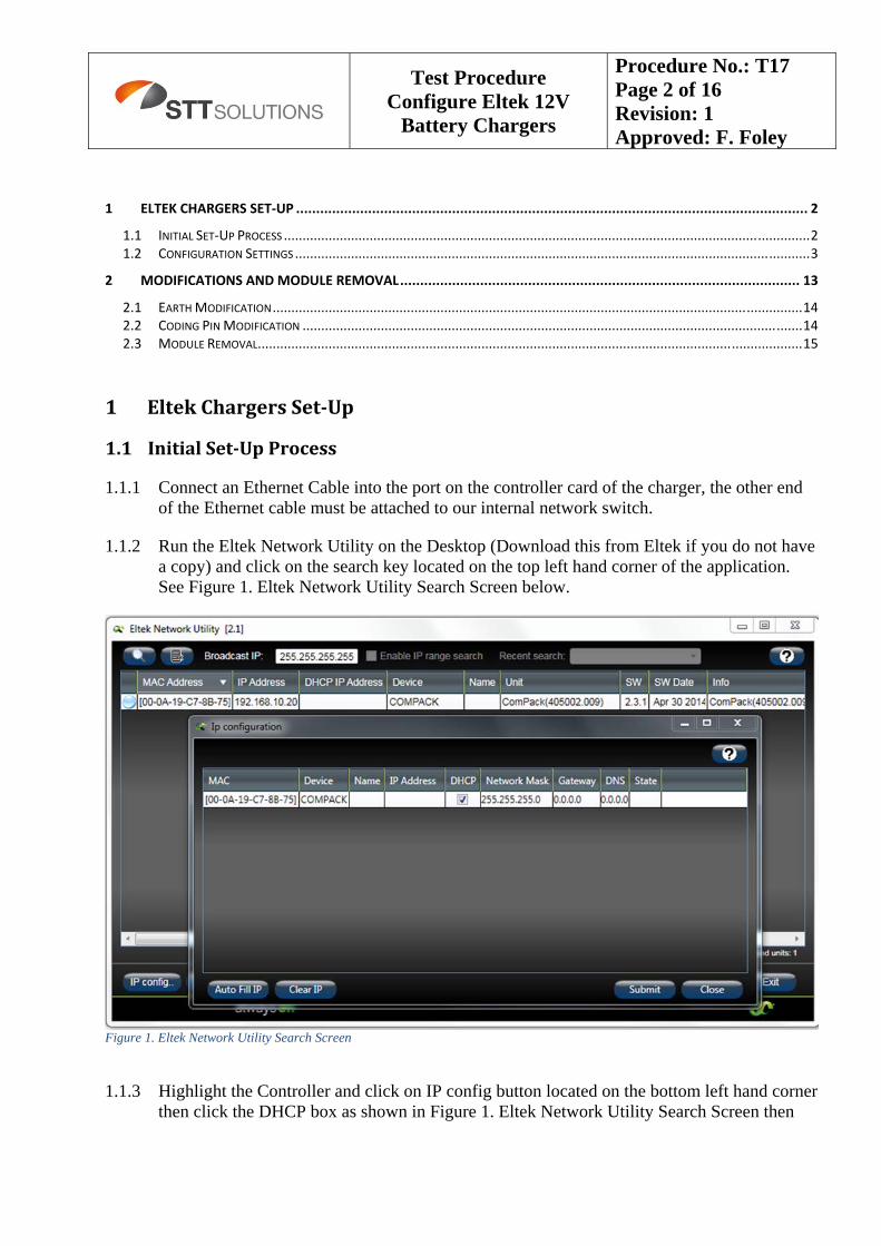
1.1.2 Run the Eltek Network Utility on the Desktop (Download this from Eltek if you do not have a copy) and click on the search key located on the top left hand corner of the application. See Figure 1. Eltek Network Utility Search Screen below.
Figure 1. Eltek Network Utility Search Screen
1.1.3 Highlight the Controller and click on IP config button located on the bottom left hand corner
then click the DHCP box as shown in Figure 1. Eltek Network Utility Search Screen then
Test Procedure Configure Eltek 12V
Battery Chargers
Procedure No.: T17 Page 3 of 16 Revision: 1 Approved: F. Foley
press the submit button.
1.2 ConfigurationSettings
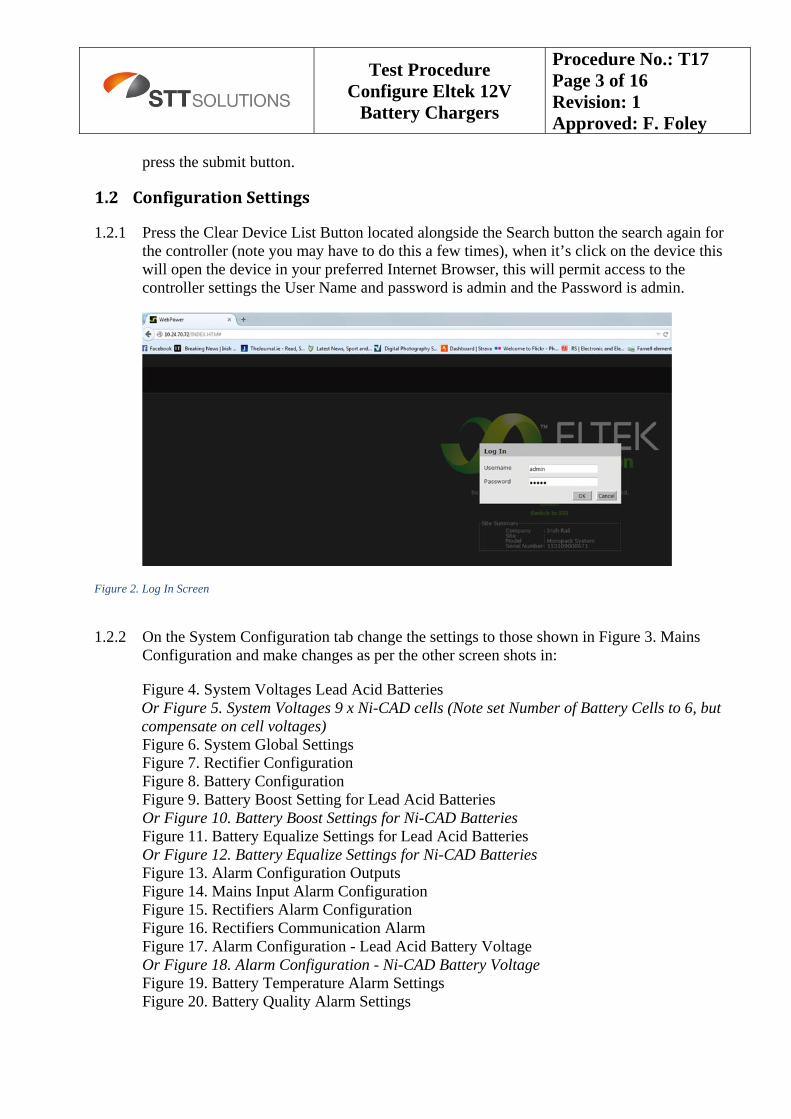
1.2.1 Press the Clear Device List Button located alongside the Search button the search again for the controller (note you may have to do this a few times), when it’s click on the device this will open the device in your preferred Internet Browser, this will permit access to the controller settings the User Name and password is admin and the Password is admin.
Figure 2. Log In Screen
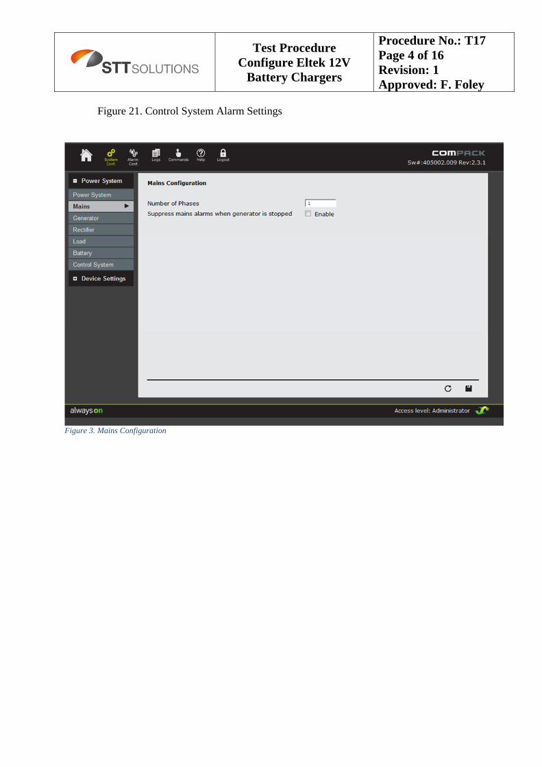
1.2.2 On the System Configuration tab change the settings to those shown in Figure 3. Mains
Configuration and make changes as per the other screen shots in:
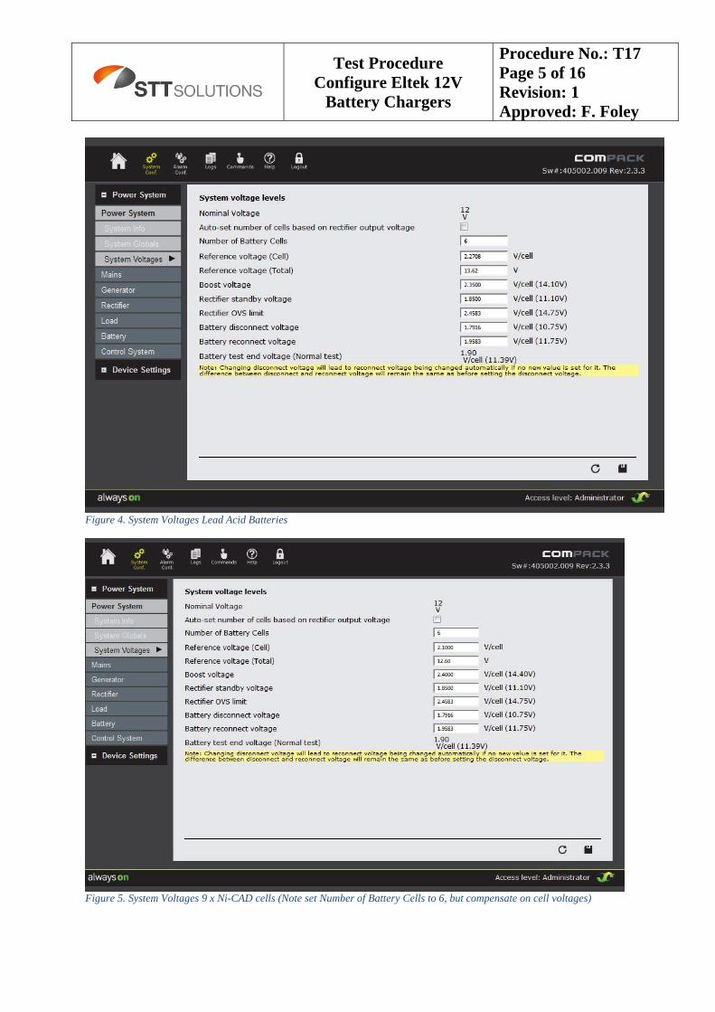
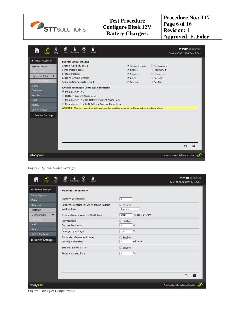
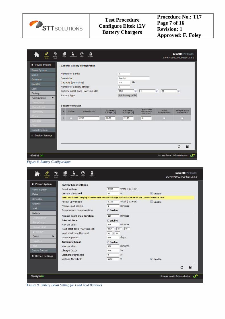
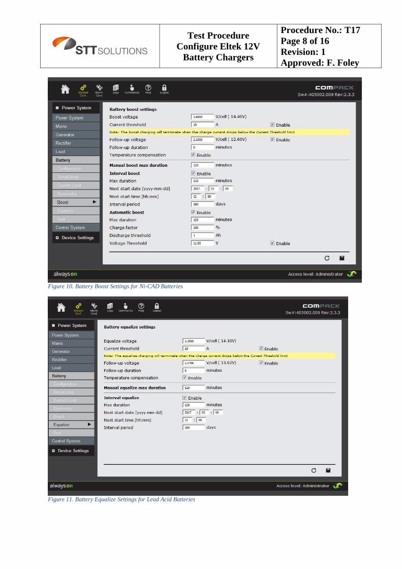
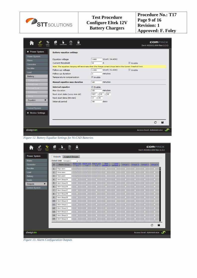
Figure 4. System Voltages Lead Acid Batteries Or Figure 5. System Voltages 9 x Ni-CAD cells (Note set Number of Battery Cells to 6, but compensate on cell voltages) Figure 6. System Global Settings Figure 7. Rectifier Configuration Figure 8. Battery Configuration Figure 9. Battery Boost Setting for Lead Acid Batteries Or Figure 10. Battery Boost Settings for Ni-CAD Batteries Figure 11. Battery Equalize Settings for Lead Acid Batteries Or Figure 12. Battery Equalize Settings for Ni-CAD Batteries Figure 13. Alarm Configuration Outputs Figure 14. Mains Input Alarm Configuration Figure 15. Rectifiers Alarm Configuration Figure 16. Rectifiers Communication Alarm Figure 17. Alarm Configuration - Lead Acid Battery Voltage Or Figure 18. Alarm Configuration - Ni-CAD Battery Voltage Figure 19. Battery Temperature Alarm Settings Figure 20. Battery Quality Alarm Settings
Test Procedure Configure Eltek 12V
Battery Chargers
Procedure No.: T17 Page 4 of 16 Revision: 1 Approved: F. Foley
Figure 21. Control System Alarm Settings
Figure 3. Mains Configuration
Test Procedure Configure Eltek 12V
Battery Chargers
Procedure No.: T17 Page 5 of 16 Revision: 1 Approved: F. Foley
Figure 4. System Voltages Lead Acid Batteries
Figure 5. System Voltages 9 x Ni-CAD cells (Note set Number of Battery Cells to 6, but compensate on cell voltages)
Test Procedure Configure Eltek 12V
Battery Chargers
Procedure No.: T17 Page 6 of 16 Revision: 1 Approved: F. Foley
Figure 6. System Global Settings
Figure 7. Rectifier Configuration
Test Procedure Configure Eltek 12V
Battery Chargers
Procedure No.: T17 Page 7 of 16 Revision: 1 Approved: F. Foley
Figure 8. Battery Configuration
Figure 9. Battery Boost Setting for Lead Acid Batteries
Test Procedure Configure Eltek 12V
Battery Chargers
Procedure No.: T17 Page 8 of 16 Revision: 1 Approved: F. Foley
Figure 10. Battery Boost Settings for Ni-CAD Batteries
Figure 11. Battery Equalize Settings for Lead Acid Batteries
Test Procedure Configure Eltek 12V
Battery Chargers
Procedure No.: T17 Page 9 of 16 Revision: 1 Approved: F. Foley
Figure 12. Battery Equalize Settings for Ni-CAD Batteries
Figure 13. Alarm Configuration Outputs
Test Procedure Configure Eltek 12V
Battery Chargers
Procedure No.: T17 Page 10 of 16 Revision: 1 Approved: F. Foley
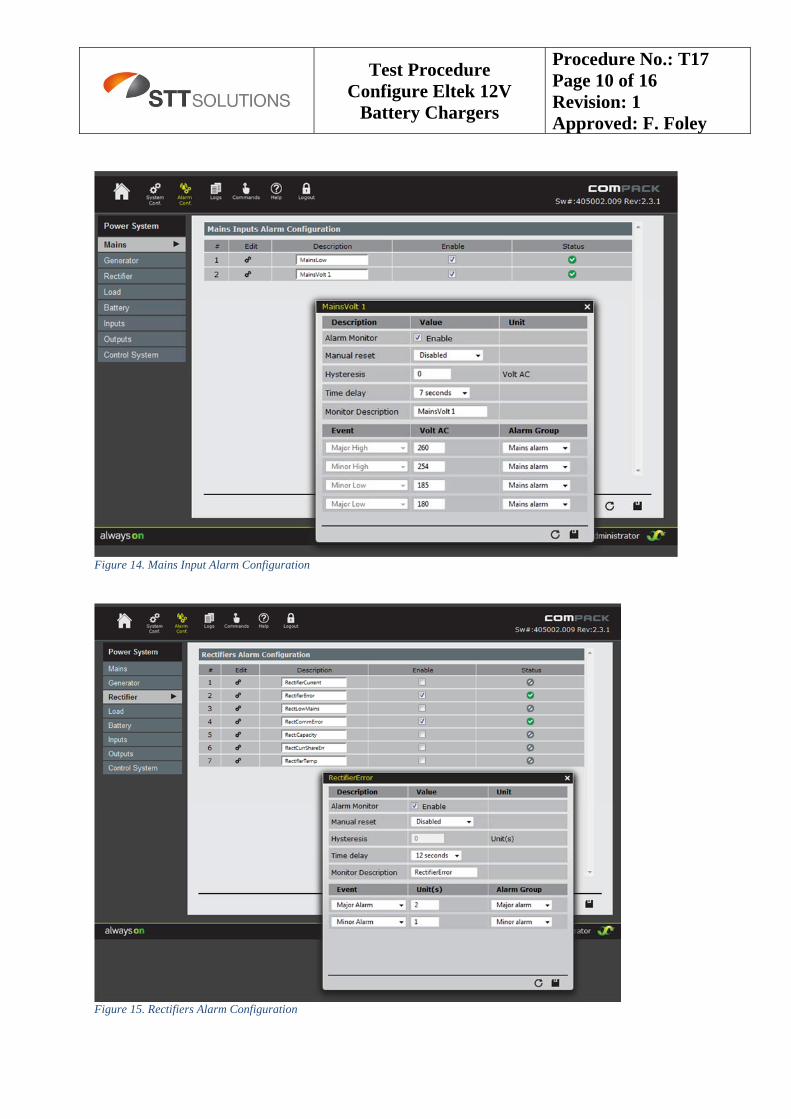
Figure 14. Mains Input Alarm Configuration
Figure 15. Rectifiers Alarm Configuration
Test Procedure Configure Eltek 12V
Battery Chargers
Procedure No.: T17 Page 11 of 16 Revision: 1 Approved: F. Foley
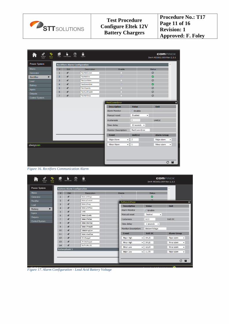
Figure 16. Rectifiers Communication Alarm
Figure 17. Alarm Configuration - Lead Acid Battery Voltage
Test Procedure Configure Eltek 12V
Battery Chargers
Procedure No.: T17 Page 12 of 16 Revision: 1 Approved: F. Foley
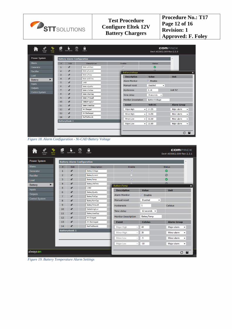
Figure 18. Alarm Configuration - Ni-CAD Battery Voltage
Figure 19. Battery Temperature Alarm Settings
Test Procedure Configure Eltek 12V
Battery Chargers
Procedure No.: T17 Page 13 of 16 Revision: 1 Approved: F. Foley
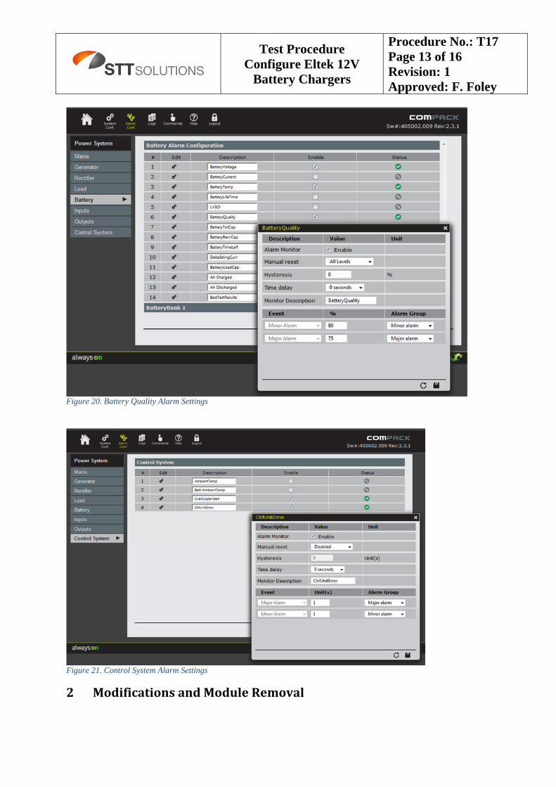
Figure 20. Battery Quality Alarm Settings
Figure 21. Control System Alarm Settings
2 ModificationsandModuleRemoval
Test Procedure Configure Eltek 12V
Battery Chargers
Procedure No.: T17 Page 14 of 16 Revision: 1 Approved: F. Foley
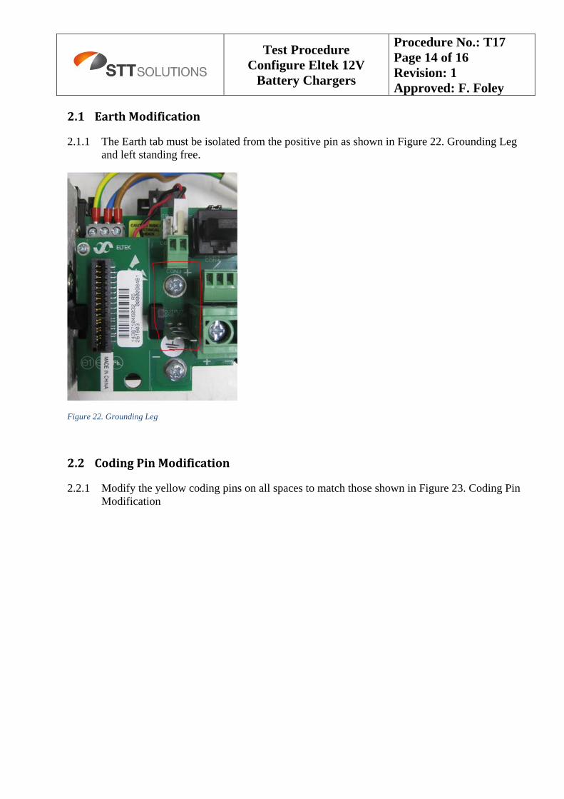
2.1 EarthModification
2.1.1 The Earth tab must be isolated from the positive pin as shown in Figure 22. Grounding Leg and left standing free.
Figure 22. Grounding Leg
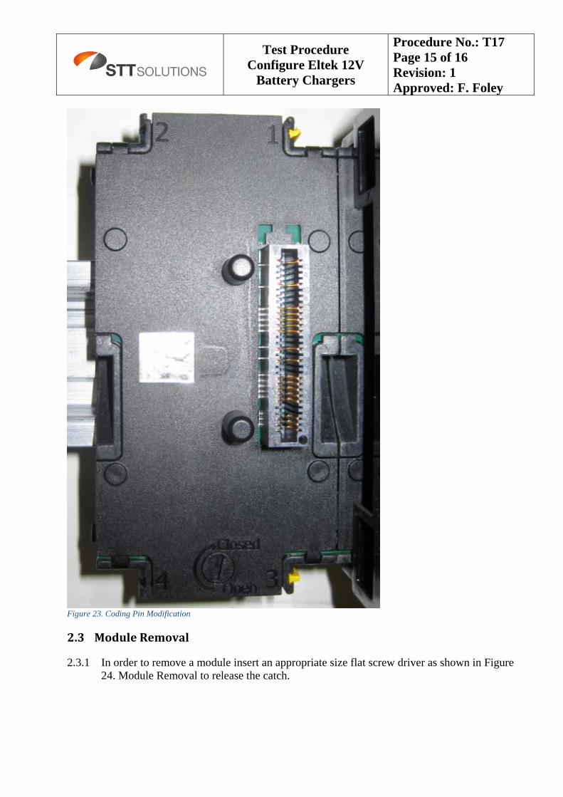
2.2 CodingPinModification
2.2.1 Modify the yellow coding pins on all spaces to match those shown in Figure 23. Coding Pin Modification
Test Procedure Configure Eltek 12V
Battery Chargers
Procedure No.: T17 Page 15 of 16 Revision: 1 Approved: F. Foley
Figure 23. Coding Pin Modification
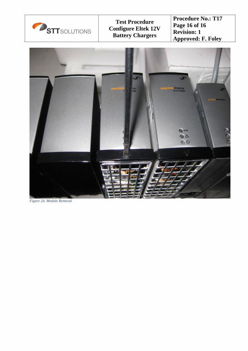
2.3 ModuleRemoval
2.3.1 In order to remove a module insert an appropriate size flat screw driver as shown in Figure 24. Module Removal to release the catch.
Test Procedure Configure Eltek 12V
Battery Chargers
Procedure No.: T17 Page 16 of 16 Revision: 1 Approved: F. Foley
Figure 24. Module Removal