Embed Size (px)
Citation preview

INEL-94/0003
Test Plan for Glove Box Testing with the Real-Time Transuranic Dust Monitor
J. K. Partin J. R. Fincke
Published October 1994
Idaho National Engineering Laboratory Lockheed Idaho Technologies Company
Idaho Falls, Idaho 83415
Prepared for the U.S. Department of Energy
Assistant Secretary for Environmental Management Under DOE Idaho Operations Office
Contract DE-AC07-94ID13223
, m , nr -r«,« DOCUMENT IS U N U S E D DISTRIBUTION O F ' n V^'
DISCLAIMER
This report was prepared as an account of work sponsored by an agency of the United States Government. Neither the United States Government nor any agency thereof, nor any of their employees, make any warranty, express or implied, or assumes any legal liability or responsibility for the accuracy, completeness, or usefulness of any information, apparatus, product, or process disclosed, or represents that its use would not infringe privately owned rights. Reference herein to any specific commercial product, process, or service by trade name, trademark, manufacturer, or otherwise does not necessarily constitute or imply its endorsement, recommendation, or favoring by the United States Government or any agency thereof. The views and opinions of authors expressed herein do not necessarily state or reflect those of the United States Government or any agency thereof.
DISCLAIMER
Portions of this document may be illegible in electronic image products, images are produced from the best available original document.

Test Plan for Glove Box Testing with the Real-Time Transuranic Dust Monitor
INEL-94/0003
Prepared by
J. K Paran, Scientific Specialist Date National Security Programs
Reviewed by
M. R. Donaldson, Project Manager Date Central Resources Management
Approved by
/<?/?//?c/ R. E. Heard, Program Manager Date BWID Deployment

ABSTRACT
This test plan describes the experimental details for the benchscale testing of the real-time transuranic dust monitor (RTDM) to be performed at the Idaho National Engineering Laboratory. The purpose of these experiments is to establish the feasibility of the RTDM as a stand-alone monitoring device for airborne transuranics and to investigate the optimal performance parameters and operational limits of the prototype. Test objectives, experimental procedures, and data quality objectives are included in the plan.
iii

iv
SUMMARY
This test plan describes the objectives, instrumentation, and testing procedures used to prove the feasibility of a real-time transuranic dust monitor (RTDM). The RTDM is under development at the Idaho National Engineering Laboratory (INEL) as a Waste Characterization Technology funded by the Buried Waste Integrated Demonstration Project The instrument is an in situ monitor that uses optical techniques to establish particle size, particle number density, and mass and species of heavy metal contamination.
U.S. Department of Energy orders mandate the assessment of radiological exposure and contamination spread during the remediation of radioactive waste. Of particular concern is heavy metal contamination of dust, both radioactive and nonradioactive. Small particles of metal, particularly the radioactive species, tend to become electrically charged and consequently attach themselves to dust particles. This airborne activated dust is a primary means of contamination transport during remediation activities, and therefore, must be continuously monitored to protect personnel involved in the operations and to control the spread of contamination. If real-time monitoring is not available there is increased likelihood of generating unacceptably high levels of contamination and being forced to shut down costly retrieval operations to decontaminate.
A series of experiments are described to determine the optimal experimental design, operational parameters, and levels of detection for the RTDM. Initial screening will be performed using monodisperse particle standards to set parameters and calibrate the instrument. Additional testing will be performed using INEL soil samples spiked with a surrogate, cerium oxide, to proof the design before transporting the apparatus to the Test Reactor Area for testing with plutonium-contaminated dusts.
The project's specific objective is designing a real-time, stand-alone monitor that can measure 10-pCi/g concentrations of transuranic-contaminated dust with particle sizes in the 0.1 to 50.0- u range.
v

vi
CONTENTS
ABSTRACT iii
SUMMARY v
ACRONYMS . . xi
1. INTRODUCTION 1
1.1 Background 1
1.2 Scope 2
1.3 Objective 2
1.4 Technology Agreement 2
1.5 Need 2
2. ORGANIZATION AND RESPONSIBILITIES 4
3. DESCRIPTION OF TEST 5
3.1 Experimental Apparatus 5
3.2 Key Input and Output Parameters 7
3.3 Testing Plans 8
3.4 Procedures 8
3.5 Test Prerequisites 8
4. SOIL SAMPLE COLLECTION 10
5. PROCEDURE FOR PREPARING CONTAMINATED SOIL SAMPLES 11
6. LASER OPERATING PROCEDURES 12
6.1 Startup Procedure 12
6.2 Shutdown Procedure 13
6.3 General Test Procedure 13
vii

6.4 Contingency Plan 15
6.5 Objectives 15
7. SEQUENCE OF ACT1V1TIES 16
8. SAMPLING AND DATA 17
8.1 Comprehensive Environmental Response, Compensation, and
Liability Act Criteria 17
8.2 Data Collection and Sample Preparation 17
9. DOCUMENT CONTROL 19
10. ANALYTICAL METHODS 20
11. DATA REDUCTION, VALIDATION, AND VERIFICATION 21
11.1 Data Reduction Techniques 21
11.2 Data Validation 22
12. QUALITY ASSURANCE 23
13. EQUIPMENT AND INSTRUMENTS 24
13.1 Equipment List 24
13.2 Calibration and Maintenance 25
14. SUPPLIES, UnLITIES, AND FACILITIES 26
15. HEALTH AND SAFETY 27
15.1 Radiological Safety 27
15.2 Laboratory Safety and Training 27
15.3 Waste Management Practices 28
16. RESIDUALS MANAGEMENTS 29
17. REFERENCES 30
viii

FIGURES
1. RTDM concept 1
2. Organizational structure 4
3. Schematic of experimental apparatus 5
4. Row cell schematic 7
ix

X

ACRONYMS
BWID Buried Waste Integrated Demonstration
CAM Constant Air Monitor
DOE U.S. Department of Energy
HEPA High efficiency particle air
INEL Idaho National Engineering Laboratory
LIBS Laser-Induced Breakdown Spectroscopy
MTR Materials Test Reactor
OMA Optical Multichannel Analyzer
ROI Region-of-Interest
RTDM Real-Time Transuranic Dust Monitor
RWP Radiation Work Permit
RWMC Radioactive Waste Management Complex
TRA Test Reactor Area
xi

Test Plan for Glove Box Testing with the Real-Time Transuranic Dust Monitor
1. INTRODUCTION
1.1 Background
This test plan defines the experimental details of studies designed to prove the feasibility of certain features of a real-time transuranic dust monitor (RTDM). The RTDM is an in situ monitor that can analyze single dust particles spectroscopically and give a virtually instantaneous electronic readout Optically-based measurements techniques are used to establish particle size, particle number density, and mass and species of heavy metal contamination.
The instrument relies on two methods (illustrated in Figure 1), laser-induced breakdown spectroscopy (LIBS) for the spectroscopic identification, and laser particle scattering for the determination of particle size and number density. LIBS is an analytical technique in which high power laser light is focused onto a sample. The intense radiation vaporizes the dust particle forming a high-temperature plasma. The plasma is highly emissive, yielding the characteristic lines of all atomic species present The particle size measurement is determined from the absolute magnitude of the scattered light as the particle traverses a Gaussian laser beam. The particle density is determined by counting single particles crossing a known focal volume with known velocity.
Number Density Dust
Particle Particle Size and Number Density
Histogram Size D i s t r i b u t i o n - ^
Sample Line Laser-Induced Breakdown Spectroscopy
Pulsed Laser m%^> Spectrograph
Particle
Composition
1 iiliil Spectra
Figure 1 . RTDM concept.
1
1.2 Scope
A series of experiments are planned to determine the optimum experimental design and operational parameters for the RTBM. The specific parameters to be evaluated through testing are the flow cell geometry, sampling rate and mass flow; focal and off-set geometry for the particle sizing system; and power level, wavelength(s) for analysis, focal volume, offset from the particle sizing laser, detector gating time and delay for contaminant measuring system. Initial screening will be performed using monodisperse particle standards to establish the optimal flow parameters, cell geometry and signal calibrations. Additional testing will be performed using INEL soil samples spiked with a surrogate, cerium oxide, to proof the design before transporting the prototype to TRA for testing with 239Pu-contaminated dust.
1.3 Objective
The specific test objectives are to (a) determine the optimum instrumental design through laboratory testing, (b) establish the operational limits and levels of detection for the device under laboratory conditions, and (c) validate these results with data from reference standards and other supporting analytical techniques.
The specific data quality objective is the design of a RTDM that can measure 10 pCi/g concentrations of transuranic contaminated dust with particle sizes in the 0.1 to 50.0-u range.
1.4 Technology Agreement
This testing is being performed at the INEL as a part of the Buried Waste Integrated Demonstration (BWID) Project as a Waste Characterization Technology, under Technical Task Plan TTP-ID1-4-20-02.
1.5 Need
U.S. Department of Energy (DOE) orders mandate the assessment of radiological exposure and contamination spread during remediation of buried radioactive waste. Of particular concern is heavy metal contamination of dust, both radioactive and nonradioactive. Small particles of metal, particularly the radioactive species, tend to be electrically charged and consequently attach readily to dust particles. This airborne activated dust is a primary means of contamination transport during remediation activities. Therefore, remediation-generated dusts must be continuously monitored to protect personnel involved in remediation operations and control the spread of contamination. If real-time monitoring is not available, there is increased likelihood of inadvertently generating high contaminant levels with subsequent required decontamination.
A knowledge of dust concentration, particle size distribution, and the type of contamination present is critical to assessing remediation hazards since airborne and surface contamination levels depend upon suspension and settling factors, which are a function of concentration and size. Although, many retrieval activities will be handled remotely, it will still be necessary for personnel to enter contaminated areas to maintain equipment and perform other tasks. In particular, a
2

knowledge of the airborne concentration levels of transuranic species will be required at these times since the uptake of small quantities (tens of micrograms) can result in lifetime doses to personnel.
In addition to monitoring transuranic contamination, the RTDM could be used to monitor Resource Conservation and Recovery Act targeted metals including Cr, Cd, Hg, Pb, Zr, Se, and Th. The RTDM has direct application to INEL's Radioactive Waste Management Complex (RWMC) and Pit 9 projects. The device could also be used in remediation activities at mixed waste facilities at Hanford, Oak Ridge, Rocky Flats, Los Alamos, Nevada Test Site, and Savannah River. A version of the device could be designed to monitor aerosol effluents from wastestreams of thermal treatment processes, now being evaluated for waste treatment, and the in situ characterization of contaminated metal parts. The development of the technology could also benefit other industries with dust control problems. For example, the construction industry could use a device to monitor asbestos removal during building renovation.
Existing hazard assessment technology relies on nonreal-time processes with sample collection, often accompanied by sample transfer to analytical laboratories and subsequent wet chemical analysis. The time from sample acquisition to offsite laboratory results can be several days. This situation is improved significantly with alpha constant air monitor (CAM) systems; although at low levels of alpha emission, the CAMs must integrate particulate samples on filter material before meaningful data are obtained. This program offers the opportunity to demonstrate a truly real-time measurement technique that can be used as a stand-alone device or in conjunction with other analytical measurement techniques.
3

2. ORGANIZATION AND RESPONSIBILITIES
The organizational affiliations and responsibilities of key personnel involved in the development and testing of the RTDM are shown in Figure 2. The prototype will be developed and tested by personnel from the Applied Physics and Optics Unit of EG&G Idaho, Inc. Surrogate dust samples will be prepared with the aid of the Analytical Chemistry Unit The glove box testing will be coordinated with personnel from the Radiation Measurements and Development Unit who will provide facilities, transuranic dust sample preparation, and radiochemical analysis support. Personnel from Applied Physics and Optics will be responsible for collecting and validating the data from the RTDM.
A radiological control technician will be responsible for radiological monitoring of the area during the experiments with transuranic-contaminated soils, and in verifying that all personnel are wearing the proper dosimetry and following radiological safety procedures. A laser safety officer will review the laser installation and alignment procedures and will ensure that the proper administrative and engineering controls are in place for safe operation. A trained laser operator from the Physics and Applied Optics Group will operate the lasers during testing.
BWID COORDINATOR K.M. Kostelnik
BWID TECHNICAL LIAISON G.G. Loomis
BWID PROGRAM MANAGER M.R. Donaldson
APPLIED PHYSICS AND OPTICS J.M. Slater, Unit Manager
J.K. Partin, Principal Investigator C.L. Jetfery
RADIATION MEASUREMENTS AND DEVELOPMENT
K.L. Martin, Unit Manager V.E. Vaughn
D.S. Sill
Figure 2. Organizational structure.
4

3. DESCRIPTION OF TEST
This section describes the experimental procedures, apparatus, methods for calibration, types of data to be collected and evaluation procedures to be used in the testing of the RTDM. The specific test objectives are to evaluate the ability of the device to detect and quantify aerosols containing transuranic-contaminated dust
3.1 Experimental Apparatus
A schematic of the experimental apparatus is shown in Figure 3. The RTDM is based upon the integration of two technologies: LIBS for identifying the species and amounts of contaminants and laser-particle scattering analysis for determining the particle size and concentration.
Pulse generator
Spectrometer
OMA Detector
OMA Controller
OMA Interface
Beam Dump
Computer
PMT
Pre _Amp_
Log Amp
Pulse-Height Analyzer
Figure 3. Schematic of experimental apparatus.
5

The particle size measurement involves the near-forward scatter from the focus of a low power helium neon (HeNe) laser beam, together with a pulse height analysis of the signals scattered from individual particles as they traverse the beam. The effective measurement volume is determined partly by the intensity distribution in the illuminating beam and partly by the geometry of the collection optics. For a given measurement volume, there is a limit to useful operation set by the occurrence of more than one particle in the measurement volume. The collection geometry angle is typically set to 10 degrees or less to minimize the sensitivity to the material properties (refractive index, roughness etc.) of the particles.
The LIBS technique is similar, in principal, to atomic emission spectroscopy, which uses an electrode spark to produce a plasma. Material is introduced into the plasma where it is vaporized, and the resulting atoms are electronically excited. The plasma is then spectrally resolved to identify emitting species. In LIBS, the plasma is formed by focusing optical pulses from a sufficiently powerful laser. Typically, a few hundred millijoules delivered in a 5 to 15-ns pulse is sufficient to generate a plasma for most analyses. This corresponds to a focused power density of tens of GW/cm2, producing plasma temperatures of 25,000 K. At these temperatures, matter in the spark is readily vaporized, reduced to its atomic constituents and electronically excited. Emitted species are then spectrally and temporally resolved (because the laser is a pulsed source, its excitation characteristics will be a function of time).
A pulsed neodymium yttrium aluminum garnet (Nd:YAG) laser is used for the spark source in the RTDM. This laser is preferred over other types due to its compatibility with optical fiber transmission, making it possible to remote the measurement for future applications. It is also among the more reliable and compact sources of pulsed energy. The laser pulse is focused onto the sample using short focal length lenses, and the spark light is collected by a lens system (or fiber cable) and is focused onto a spectrometer to select the emission line or lines characteristic of the species to be monitored.
The spectrally-resolved light is detected by a photodiode array, which can record a spectra from a single laser shot The photodiode array is gated to time the data collection from the occurrence of the laser spark. This reduces contributions from unwanted background signals. The combination of pulse generator, photodiode array, and control software is referred to as an optical multichannel analyzer (OMA).
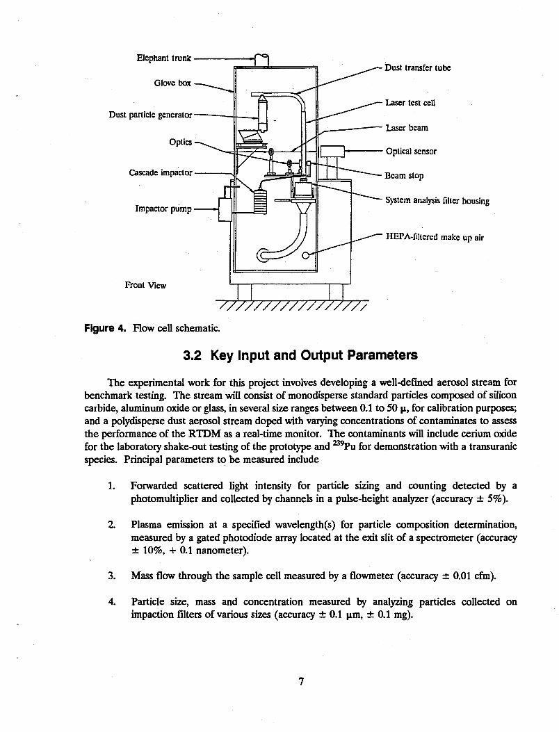
The flow cell apparatus is shown in Figure 4. The flow cell consists of a fluidized bed aerosol generator, a 5-cm2 plexiglass test section with an aluminum section, containing rectangular windows for optical access, and an impactor stage containing isopore filters (with 50, 25,12, 5, .6, .1-u pores) for particle collection and sizing. Airflow is supplied by a rotary vane pump that can be varied over a wide range of flow rates (5 to 200 L/minute).
For the testing with transuranic-contaminated soils to be performed at the TRA facilities, the flow cell will be installed in a containment box with high efficiency particulate air (HEPA) filtering, glove ports, and windows for optical access. This fixture will be placed in a hot hood.
6
Elephant trunk
Glove box
Dust particle generator
Optics
Cascade impaclor
Impactor pump
Front View
Dust transfer tube
Laser test cell
Laser beam
Optical sensor
Beam stop
System analysis filter housing
HEPA-filtcred make up air
77777777777777777 Figure 4. Row cell schematic.
3.2 Key Input and Output Parameters
The experimental work for this project involves developing a well-defined aerosol stream for benchmark testing. The stream will consist of monodisperse standard particles composed of silicon carbide, aluminum oxide or glass, in several size ranges between 0.1 to 50 |i, for calibration purposes; and a polydisperse dust aerosol stream doped with varying concentrations of contaminates to assess the performance of the RTDM as a real-time monitor. The contaminants will include cerium oxide for the laboratory shake-out testing of the prototype and 2 3 9 Pu for demonstration with a transuranic species. Principal parameters to be measured include
1. Forwarded scattered light intensity for particle sizing and counting detected by a photomultiplier and collected by channels in a pulse-height analyzer (accuracy ± 5%).
2. Plasma emission at a specified wavelength(s) for particle composition determination, measured by a gated photodiode array located at the exit slit of a spectrometer (accuracy ± 10%, + 0.1 nanometer).
3. Mass flow through the sample cell measured by a flowmeter (accuracy ± 0.01 cfm).
4. Particle size, mass and concentration measured by analyzing particles collected on impaction filters of various sizes (accuracy ± 0.1 um, ± 0.1 mg).
7

3.3 Testing Plans
The tests include a series of five calibration runs consisting of monodisperse particle standards (silicon carbide, glass, or alumina) to establish the optimal operational parameters and to calibrate signal levels. Operational parameters to be determined include
1. Optimal focal volume and geometric offset for the particle sizing laser.
2. Optimal operational power level, focal volume, and offset from the particle sizing beam for the contaminant beam.
3. Optimal particle feed rate and mass flow through the sampling volume.
A series of five tests will be run using a polydisperse INEL soil blank to establish a background and to look for spectral interferences from naturally occurring soil species, such as Si, Ca, Mg, or Fe. A series of three tests will also be performed using a soil blank doped with varying concentrations (100, 10, 1, 0.1 ppm) of a surrogate species.
These tests will be performed at the INEL's IF 603, Laboratory B10 and will allow optimization of the RTDM before transporting the instrumentation to Materials Test Reactor (MTR) 604, Laboratory 113 where the testing with 239Pu-contaminated soil will be performed. For these tests, five 15 g INEL soil blanks will be doped with 100,10,1, 0.1, and 0.0 ppm quantities of ^'Pu. These tests will consist of three data runs.
3.4 Procedures
At a typical detection limit of 1 ppm weight/weight for atoms in air, a nanogram mass of material can be detected in a single laser shot. This corresponds to an activity level of approximately 60 pCi. By adding contributions from multiple shots, this detection limit can be much lower. The data produced by this test will be used to develop correlations between our sampling and the 300 pCi/g derived air concentrations level detected in a 8-hour period specified by DOE orders.
3.5 Test Prerequisites
1. Procedures approved by the Independent Safety Review Group.
2. Laser operation approved by Laser Safety Officer.
3. Radiological controls reviewed and approved by radiological engineering.
4. Radiation Work Permit (RWP) issued by TRA Radiation Control (RadCon).
5. Glovebox tested and approved by industrial hygiene.
6. Instruments calibrated to requirements established by the principal investigator.
8
7. Plutonium-contaminated test samples prepared.
8. HEP A vacuum available.
9. Test equipment tested and functioning.
10. Dust collection filters preweighed.
11. Cascade impactor filters weighed.
12. Waste disposal method predetermined.
13. Protective equipment (laboratory coats, laser goggles, gloves, and bags) as specified by RWP available in laboratory.
14. Radiation Hazard Analysis established by RadCon technician.
9

4. SOIL SAMPLE COLLECTION
Nonradioactive soil samples will be selected from the vicinity of the Cold Test Pit The soil will be dug up with a small hand trowel, placed in a polyethylene bag, and labeled with the location and time of collection. The sample will be surveyed to ensure that there is no contamination present and then sent to the radiological laboratories for doping.
10

5. PROCEDURE FOR PREPARING CONTAMINATED SOIL SAMPLES
1. Place 159 of 200 mesh soil in a 250-mL beaker.
2. Add enough water to thoroughly wet and suspend the soil.
3. Stir the soil mixture and add HC1 dropwise until the liberation of C02 is complete.
4. Stir the soil mixture and slowly add a known activity (corresponding to the of 2 3 9 Pu) in about 10 mL of solution.
5. Stir the mixture during the addition of the plutonium to avoid "hot spots" from being formed.
6. Heat the 250 Ml beaker on a hot plate and stir the mixture until the soil is immobile .
7. Continue to heat, until the soil is dry.
8. Break up the big clumps of spiked soil with a stirring rod.
9. Transfer the soil quantitatively to a mortar and grind to fine power.
10. Blend the spiked ^ 'Pu with "clean" unspiked soil in ratios to be determined.
11. Screen the contaminated soil through a 200 mesh screen.
12. Weigh the soil standard and calculate the specific activity of ^'Pu.
11

6. LASER OPERATING PROCEDURES The RTDM uses two laser systems. A10-MW Uniphase HeNe (Class mb) is used in the light
scattering measurements and a pulsed Continuum Nd:YAG (Class IV) is used in the laser breakdown measurements. The class IV laser, of course, presents a greater hazard and drives the majority of the safety concerns.
The RTDM testing is to be performed in Laboratory 109 of MTR 604 and is anticipated to last for 1 to 3 weeks. Due to the limited duration of the work, the experiment can be considered to be a Temporary Laser Installation." Under these conditions, the lasers may be administratively controlled by a qualified laser operator. In the procedures, a nominal hazard zone is defined, access to the area is blocked, and warning signs, including directions for obtaining access, are posted. (A nominal hazard zone is generally defined as the zone in which an unprotected individual could receive skin or ocular damage due to a diffuse reflectance of the laser beam.)
In the proposed activity, the control of the lasers will be administered by a qualified Laser Operator in the Applied Physics and Optics unit. A nominal hazard zone has been calculated by the Laser Safety Officer, and determined to be 3.5 m for the Nd:YAG operating at full power (420 millijoules in a 5 to 7-ns pulse, with repetition rate of 20 Hz). The 3.5-m zone defines the range over which ocular damage could occur from an accidental viewing of diffuse reflection. The calculations indicated that goggles, filtering the Nd:YAG wavelength, of optical density 6 are required for protection from this radiation. This is a conservative estimate since the beam is propagated into a lexan box and no adjustment has been made for the absorption of the box. In addition, during routine operation the beam will be attenuated, by a polarizing optical assembly, to approximately 100 millijoules.
For the tests, Laboratory 109 will be defined as a "Temporary Laser Laboratory." The entire laboratory will be controlled as a nominal hazard zone during laser operation. The door to the laboratory will be locked, and a sign advising visitors that a high power laser is in operation and permission from the laser operator is required before entry will be posted. Personnel requiring entry into the area will be issued Nd:YAG filtered goggles of optical density 6 or higher.
6.1 Startup Procedure
1. Clear all unnecessary personnel out of the work area. During the initial system alignment, only qualified laser operators will be allowed in the laboratory.
2. Remove any shiny reflective surfaces (rings, watch bands, metal pencils, etc.) before activating the laser.
3. Secure laboratory, and post warning signs and directions for obtaining entry.
4. Place baffling in front of HeNe laser, place key switch and turn to "on" position, turn power switch to "on," and observe beam on baffle.
12

5. Using tracing materials to carefully observe and control beam position, align into test fixture. Take care to not be eye level with beam during alignment, and adjust components so that back reflections are blocked from accidental viewing.
6. Before activating the Nd:YAG laser, confirm that all personnel in the laboratory have put on the appropriate laser safety glasses and inform them that the laser is being activated.
7. Place power meter in front of laser aperture and at beam dump position.
8. Insert key into key switch and turn counterclockwise to "one."
9. Press "start" button to activate laser. Allow the laser to warm up for 1 to 15 minutes.
10. Slide shutter to "open" position.
11. Press "shutter" button. Laser should emit a pulse.
12. Measure average power transmitted into test cell and adjust to 0.25 W.
13. Using proper baffling, the infrared viewer, and a beam tracing card, observe the beam path into the cell and verify alignment. Take care not to be at eye level with the beam during any part of this procedure, and be careful to adjust components so that back reflections are blocked from accidental viewing.
6.2 Shutdown Procedure
1. Depress Start/Stop button on Nd:YAG laser.
2. Slide shutter to "close" position.
3. Turn key switch to "off" and remove key from key switch to prevent unauthorized activation of laser.
4. Turn laser power "off on HeNe laser and remove key from key switch to prevent unauthorized turn-on.
5. Unlock laboratory and remove warning signs.
6.3 General Test Procedure
1. Install preweighed 5-in. Watman EPM-2000 fiberglass filter in the filter housing.
2. Install preweighed filters in the Cascade Impactor and attach to test cell 1.
3. Ensure that air flow through the duct to the HEPA-filtered hood is maintaining a negating pressure in the glovebox.
13

4. Using appropriate radiological practices, load the plutonium-contaminated dust into the dust generator using a HEP A filtered hood, then move the dust generator to the glovebox and install on the test cell Note: The initial test will be performed using an uncontaminated soil sample (blank) to serve as an data control, ensure proper operation of the equipment, and allow personnel to become more familiar with the test procedures before handling contaminated material.
5. Verify that the Laser Safety Controls (attached procedure) are in place prior to activating lasers.
6. Turn on the lasers and other monitoring equipment and allow to warm up for 10 to 15 minutes.
7. Measure and adjust laser power to predetermined values and verify alignment
8. Establish predetermined air flow through cell by turning on the vacuum blower.
9. Start cascade impactor air flow.
10. Start dust particle generator vibrator and adjust air flow for dust generation (typically 0.04 to 0.06 cfm).
11. Perform tests and record data. Specific data to be recorded include (a) sample concentration, (b) NdrYAG power, (c) mass flow rate, (d) time of test start, (e) photomultiplier output, (f) photodiode array output as a function of wavelength, (g) time test terminated, and (h) filter weights before and after test runs.
12. Turn off dust particle generator, air flow, and vibrator.
13. Turn off air flow through the test cell.
14. Deactivate lasers.
15. Remove filters from the filter housing.
16. Disconnect the cascade impactor.
17. Bag and transfer the filters to a HEPA filtered hood for weighing/analysis.
18. Clean equipment and prepare for subsequent tests.
A total of 15 test runs are planned consisting of three runs at each concentration. A run lasts for approximately 15 minutes and deposits around 0.1 to 0.5 g of material on the filter. (In the impactor, this material is partitioned among eight filters.)
14

6.4 Contingency Plan
The project is currently on schedule, and no contingency plans have been formulated. If there are any unanticipated delays in equipment deliveries or personnel scheduling conflicts, a reexamination of the test schedule, with the appropriate corrective action, will be initiated. Possible actions might include extended work weeks or a schedule slip.
6.5 Objectives
Performance objectives assess the ability of the RTDM to detect and quantify airborne transuranic-contaminated dust. Specific objectives for this test plan are to develop a calibration curve that can be used to evaluate the levels of detection for the instrument in its present design configuration.
These data will be used to determine the feasibility of using the RTDM as a stand-alone monitoring device.
15

7. SEQUENCE OF ACTIVITIES
Test Plan Reviewed by BWID 6/27/94
Complete Fabrication of RTDM 7/01/94
Prepare Nonradioactive Dust Standards 7/08/94
Calibrate RTDM Using Dust Standards 8/01/94
Prepare Radioactive Dust Samples 9/05/94
Install RTDM at TRA Facility 9/22/94
Complete "Quick Look" Testing with Transuranic-contaminated Dust 10/24/94
Evaluate and Report Results to BWID Program Manager 10/31/94
16

8. SAMPLING AND DATA
8.1 Comprehensive Environmental Response, Compensation, and Liability Act Criteria
The RTDM is a real-time, on-line device designed to analyze single dust particles for the presence of heavy metals, including transuranics species. The performance objectives are to produce a robust, fieldable prototype that can screen contaminated dust accurately enough to provide an early warning for potential personnel and contamination hazards. The use of the device eliminates the need for manual sample collection and handling, reducing unnecessary exposure to hazardous materials. The use of the device produces no secondary wastestreams.
The RTDM is based upon two mature technologies: LIBS and laser light scattering. Both of these techniques form the basis of existing laboratory instrumentation, which are known and accepted by environmental regulators. This technology is comparable to the types of high-tech equipment the public is accustomed to seeing in medical facilities and should be readily accepted by the public.
The estimated start-up costs are approximately $850,000. This figure includes $750,000 for development and demonstration and $100,000 for deployment costs. Yearly maintenance costs are estimated at $20,000/year.
The initial development and testing of the RTDM will be performed in the Applied Physics and Optics Laboratories at the INEL's Idaho Research Center. The technologies involved, laser spectroscopy and light scattering, have been performed at this facility since it was occupied in the early 1980s. Several analytical chemistry laboratories are also available for the sample preparation and analysis activities. Because this type of work is ongoing, no modifications to the facility are required for the tests.
The prototype will be tested using plutonium-contaminated dust, in the Radiation and Measurements Unit laboratories at TRA. This type of activity is also commonly performed at this facility, and similar types of testing have been conducted by other programs. (Development work for the Rapid Transuranic Monitoring Laboratory is an example.) No modification to this facility will be required for this program.
The activities fall under current regulatory guidelines for these facilities because no wastes, emissions, or effluents will be generated above what is considered normal.
8.2 Data Collection and Sample Preparation
The data from the RTDM will consist of digitized voltages representing the scattered particle intensities and spectral emission intensities. This data will be collected on a personal computer for subsequent analysis and evaluation. Other data to be collected includes mass flow through the sample cell measured by a flowmeter, filter weights before and after particle deposition, recorded into a laboratory notebook, and a chemical analysis of the concentration of deposited material on the filter, provided by letter to the principal investigator from the radiochemist performing the analysis.
17

The samples will include standard alumina and silicon carbide particles obtained from Duke Scientific, Inc. INEL soil is collected and prepared by sieving to remove the coarse particles and dried.1 ,2 The soils are then doped with known concentrations of contaminants, generally by an acid dissolution step to prepare a standard solution, followed by introducing a specific volume of the solution into a measured weight of soil. The soil is then homogenized, dried, and sieved. The details for spiking soils to produce radiological standards.3
18

9. DOCUMENT CONTROL
The data from the tests will be collected in laboratory notebooks, equipment logbooks, and computer files. Copies of pertinent laboratory notebook pages and computer files will be duplicated and delivered to BWID at the end of each day of testing. Data to be maintained includes sample identifications, date of analysis, photographs of the equipment, experimental set-up and initial settings, peak-height data for particle sizing, spectral scans and line intensity data for composition measurements, flow rates for the fluidized bed aerosol generator and sample cell, filter sizes and weights before and after sampling, sampling times and filter contaminant concentrations. Procedures for sample preparation and analysis, and equipment operational parameters, will also be recorded in logbooks.
The experimental logbooks, which are periodically microfilmed, will remain in the custody of the principal investigator until they are released to record storage. Testing results will be reported in informal reports and technical publications.
Changes to the test plan will be initiated by the principal investigator by submitting a letter of requesting and explaining the change to the BWID project manager who will review and approve/disapprove the change.
19

10. ANALYTICAL METHODS
The concentration of ^ 'Pu is determined by a radiochemical separation followed by an analysis of the separated fraction using alpha spectroscopy. The sample is put into solution through high temperature fusion followed by acid dissolution. Following a barium sulfate precipitation, the solid is dissolved in alkaline ethylenediaminetetraacetic acid and precipitated as Ce(OH)2 for alpha spectroscopy. Plutonium can also be analyzed in soil and filter samples by large area alpha spectroscopy. The samples are ground, sieved, and then mixed with ethanol and sprayed on a plate to be counted.
The particle size distributions and mass concentrations are evaluated by weighing impaction filters, sized to collect particles in various size ranges, before and after sampling. The filters are weighed on a mass balance to an accuracy of 0.1 mg. Total concentration of dust in various sizes can then be calculated from a knowledge of the flow data.
20
11. DATA REDUCTION, VALIDATION, AND VERIFICATION
11.1 Data Reduction Techniques
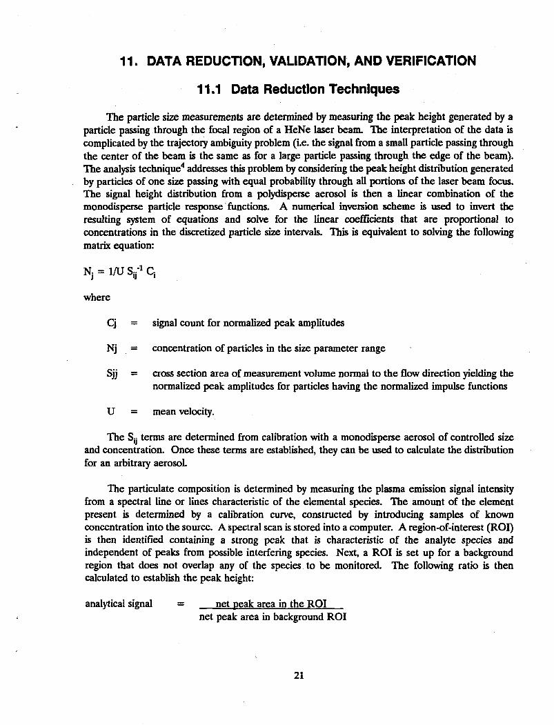
The particle size measurements are determined by measuring the peak height generated by a particle passing through the focal region of a HeNe laser beam. The interpretation of the data is complicated by the trajectory ambiguity problem (i.e. the signal from a small particle passing through the center of the beam is the same as for a large particle passing through the edge of the beam). The analysis technique4 addresses this problem by considering the peak height distribution generated by particles of one size passing with equal probability through all portions of the laser beam focus. The signal height distribution from a polydisperse aerosol is then a linear combination of the monodisperse particle response functions. A numerical inversion scheme is used to invert the resulting system of equations and solve for the linear coefficients that are proportional to concentrations in the discretized particle size intervals. This is equivalent to solving the following matrix equation:
Nj = i/u s^1 q
where
Cj = signal count for normalized peak amplitudes
Nj = concentration of particles in the size parameter range
Sjj = cross section area of measurement volume normal to the flow direction yielding the normalized peak amplitudes for particles having the normalized impulse functions
U = mean velocity.
The Sjj terms are determined from calibration with a monodisperse aerosol of controlled size and concentration. Once these terms are established, they can be used to calculate the distribution for an arbitrary aerosol.
The particulate composition is determined by measuring the plasma emission signal intensity from a spectral line or lines characteristic of the elemental species. The amount of the element present is determined by a calibration curve, constructed by introducing samples of known concentration into the source. A spectral scan is stored into a computer. A region-of-interest (ROI) is then identified containing a strong peak that is characteristic of the analyte species and independent of peaks from possible interfering species. Next, a ROI is set up for a background region that does not overlap any of the species to be monitored. The following ratio is then calculated to establish the peak height:
analytical signal = net peak area in the ROI net peak area in background ROI
21

11.2 Data Validation
The data from the RTDM will be analyzed and validated by the principal investigators from the Applied Physics and Optics Unit. A minimum of three data runs will be collected per sample concentration and compared. It anticipated that these runs should agree within 15%. In addition, the data taken from the RTDM will be compared to the independent particle size, mass, and species concentration data analyzed from the collection Alters, and an evaluation will be performed to determine if the two data sets correlate within the known measurement uncertainties.
22

12. QUALITY ASSURANCE
Hie RTDM development and testing will be performed in accordance with Quality Program Plan, QPP-044, Rev. E and Environmental Restoration, ERA SP3.1, Quality Assurance. In accordance with this document, the principal investigator has the primary responsibility to ensuring the quality of the research and development of a product This responsibility requires the development, documentation, and peer review of the system specifications, the tracking of system components to ensure that they meet the desired requirements, and the proofing of the instrument through laboratory testing.
The quality of the data will be controlled through the following means:
1. All experimental equipment will be calibrated to ensure data collection integrity.
2. The RTDM will be calibrated against commercial standard particle streams.
3. All tests will be repeated a minimum of three times.
4. Supporting data will be analyzed by personnel from different organizations using alternative measurement techniques.
Changes in procedures will be authorized and documented by the principal investigator. Laboratory notebooks will be signed and dated by the personnel entering the data.
23

13. EQUIPMENT AND INSTRUMENTS
The equipment for the test will be provided by the Applied Physics and Optics organization.
13.1 Equipment List
RTDM:
• Uniphase Model 1125P, 10 MW, Helium Neon Laser, 633-nanometer wavelength
• TSI Optical Collection Optic, Model 9140, with Melles Griot 390 Micron Pinhole Aperture
• Hamamatsu, Model R928, Photomultiplier Detector, spectral response 185 to 930 nanometer, sensitivity 6.8 x 10⁵ A/W, amplification 1.0 x 107,2.2-ns rise time, housed in a Pacific Model 3150RF housing
• Ithaco Model 1211 Current Amplifier, 10-3 to 10-in. A/V gain, with nine decade current gain ranges, rise time 10 (is to 1 second
• LeCroy 9450 Digital Oscilloscope, 350 MHz Bandwidth, 10 GS/s random interleaved sampling, nonvolatile 50K memory, IEEE interface
• IBM Model 70 (386) personal computer with National Instruments MC-GPIB Interface
• Continuum, Surelight Model 1-20, pulsed Nd:YAG laser, 420 mJ in 5 to 7 ns with a 20-Hz repetition rate, 1,064-nanometer wavelength
• Focusing Lens, 25.4-mm diameter, 25.4-mm focal length fused silica
• Acton Research Corporation, SpectaPro-500 spectrometer, 0.5-m CzernyTurner type, 0.05-nm resolution with 1,200-g/mm grating
• Optical Fiber Coupler, 1-m quartz optical fiber cable with spectrometer adapter
• Princeton Instruments, Inc., Model PG-200, programmable gate pulse generator, continuously adjustable in 1-ns increments up to 80 ms.
• Princeton Instruments, Inc., Model IRY-700S, proximity focused multichannel plate image intensified diode array detector, spectral range 200 to 800 nanometer, 14-bit dynamic range with better than 1% linearity, gating on/off 106 or greater, gatable to 50 ns
• Princeton Instruments, Inc., Model ST-120, direct memory access controller for IBM Cone Computer, controls power, thermostating, shutter control, and timing signals to detector head with eight programmable input and output ports
• Dell 50 MHz 486 Computer, 200 MB hard disk, 8 MB RAM, DOS 6.0 Operating System
24

Molectron Laser Power Meter
• Neslab Recirculating Chiller
• Transportable Optical Table
Flow Cell:
• Fluidized bed
• Aluminum and plexiglas flow duct with optical windows
• Containment box with HEPA filters, glove ports, and optical windows
• Flow Tech FT12M206GB Transducer with LFA Sensor Electronics and Tech DC505A Frequency Counter, 2 to 20 ACFM
• Anderson 1 AFCM Impactor with nine impaction stages
• Fiberglass particle filters
• Ametek, Model 4M963, 5.7-in. brushless blower, 90 cfm (2-in. orifice)
Analysis:
• Duke Scientific Particle Standards (0.1 to 100- u diameter glass spheres)
• Mettler, Model AJ100 Mass Balance, 0.1 mg
• Large-Area Ionization Chamber Alpha Spectrometer, Ordela Models 8200A and 8210A.
13.2 Calibration and Maintenance
The RTDM is maintained in accordance with directives from the operational manuals supplied with each of the components. The lasers may require some alignment of the resonator cavity mirrors after being moved, a procedure for this alignment is found in the manuals. After hundreds of hours of operation, the flashlamps and crystal rod may require replacement in the high power laser. Off-normal conditions are usually recognized from a decrease in laser power. The laser power is measured with a power meter that is calibrated by the factory. The spectral detection system is calibrated using a spectral calibration lamp standard. The entire device is calibrated using commercial particle standards. The flow cell and optical windows may require periodic cleaning by an air purge.
The mass balance and alpha spectrometer are calibrated using laboratory standards. The flowmeters and other supporting analytical equipment are calibrated by the EG&G Idaho Calibration Laboratory before use.
25

14. SUPPLIES, UTILITIES, AND FACILITIES
The RTDM testing with transuranics with require access to radiological laboratory facilities. A hot hood is required and approximately 2 x 3-m floor space nearby is required for the equipment A 208 V, single phase, 10-amp circuit is required for the laser. Approximately 0.2 L of transuranic-contaminated soil is required for testing. The facilities and support for this activity will be provided by the Nuclear Research and Engineering organization.
26

15. HEALTH AND SAFETY
The experiments will involve the exposure of personnel to several types of hazards including ionizing and non-onizing (laser) radiation, chemical, and electrical hazards. It is the policy of EG&G Idaho to ensure that personnel working on experiments are aware of the hazards present and are trained to work safely.
The practices discussed in the following sections will be used to reduce risks.
15.1 Radiological Safety
Work will be performed in accordance with guidelines established in the EG&G Idaho Radiological Controls Manual. Specific sections of interest include
Chapter 3, "Airborne Radioactivity Limits, HEPA Filter Requirements, Monitoring for Airborne Radioactivity"
Chapter 4, "Enclosure for Containing Contamination and Severe Measurements"
Chapter 5, "Constant Air Monitors, Instrument Calibration and Control, Selection and Installation of Continuous Air Monitors"
Chapter 11, "Continuous Availability of RadCon Personnel, Inspecting Radiological Work, Planning Radiological Controls, Radiation Worker Training, Radiological Controls, Review and Approval."
15.2 Laboratory Safety and Training
Work will be performed in accordance to the Science and Technology Standard Practices Manual. Specific sections of interest include
Section 2.1.5 "Eye Protection and Protective Clothing" Section 2.1.6 "Laboratory Safety" Section 2.1.8 "Laboratory Hood Use" Section 2.1.9 "Laser Safety" Section 2.2.4 "Radioactive Materials Handling" Section 2.2.5 "Glove Box Handling" Section 2.2.7 "Laboratory Radiological Handling."
Electrical safety concerns are addressed in the EG&G Idaho Safety Manual. Sections include
Section 10.4.1 "General Electrical Safety Requirements" Section 10.4.5 "Employees Exposed to Electrical Hazards."
27

15.3 Waste Management Practices
Waste management policies are prescribed in Section 2 of the Science and Technology Standard Practices Manual and Environmental Restoration Standard Practices Manual, Section 4. Specific sections of interest include
Section 2.1.1 "Nonradioactive Chemical Waste Disposal" Section 2.1.3 "Chemical Lab Inventory" Section 2.1.4 "Chemical Spill Control" Section 2.2.9 "Handling and Storage of Hazardous Waste in Satellite Accumulation Areas" Section 4.9 "Radioactive Management at IRC and TRA."
28

16. RESIDUALS MANAGEMENTS
The project will produce approximately 0.2 L of low-level 23*Pu-contaminated soil and filter materials and approximately 1/2-m2 volume of other contaminated components from the test apparatus. Disposal of these materials will occur at the RWMC in accordance to their waste acceptance criteria.
*
29

17. REFERENCES
P.G. Shaw, et. aL Test Plan for Contamination Control Related Experiments, EGG-WTD-9059, EG&G Idaho, Inc., March 1990.
C.V. Mclsaac e t al. Test Plan for Demonstration of Rapid Tmnsuranic Monitoring Laboratory, EGG-WTD-10758, EG&G Idaho, Inc., June 1993.
C.W. Sill and F.D. Hindman, "Preparation and Testing of Standard Soils Containing Known Quantities of Radionuclides", Anal Chem., Vol 46, pp. 113-118.
D. Holve and S.A. Self, "Optical Particle Sizing for In-Situ Measurements, Parts 1 & 2," App. Opt., Vol 18, pp. 1632-1652.
30


![Cyborg Glove ExcerptNick and Tesla’s Super Cyborg Gadget Glove [Excerpt]](https://img.pdfslide.us/doc/110x75/577cc47a1a28aba711996e65/cyborg-glove-excerptnick-and-teslas-super-cyborg-gadget-glove-excerpt.jpg)