Embed Size (px)
Citation preview
Test of the transmission line model and the traveling current source
model with triggered lightning return strokes at very close range
J. Schoene, M. A. Uman, V. A. Rakov, K. J. Rambo, J. Jerauld, and G. H. SchnetzerDepartment of Electrical and Computer Engineering, University of Florida, Gainesville, Florida, USA
Received 11 April 2003; revised 7 August 2003; accepted 22 August 2003; published 11 December 2003.
[1] We test the two simplest and most conceptually different return stroke models, thetransmission line model (TLM) and the traveling current source model (TCSM), bycomparing the first microsecond of model-predicted electric and magnetic field waveforms and field derivative wave forms at 15 m and 30 m with the corresponding measuredwave forms from triggered lightning return strokes. In the TLM the return strokeprocess is modeled as a current wave injected at the base of the lightning channel andpropagating upward along the channel with neither attenuation nor dispersion and at anassumed constant speed. In the TCSM the return stroke process is modeled as acurrent source traveling upward at an assumed constant speed and injecting a current waveinto the channel, which then propagates downward at the speed of light and is absorbed atground without reflection. The electric and magnetic fields were calculated fromMaxwell’s equations given the measured current or current derivative at the channel base,an assumed return stroke speed, and the temporal and spatial distribution of the channelcurrent specified by the return stroke model. Electric and magnetic fields and theirderivatives were measured 15 m and 30 m from rocket-triggered lightning during thesummer of 2001 at the International Center for Lightning Research and Testing at CampBlanding, Florida. We present data from a five-stroke flash, S0105, and compare themeasured fields and field derivatives with the model-predicted ones for three assumedlightning return stroke speeds, v = 1 � 108 m/s, v = 2 � 108 m/s, and v = 2.99 � 108 m/s(essentially the speed of light). The results presented show that the TLM works reasonablywell in predicting the measured electric and magnetic fields (field derivatives) at 15 mand 30 m if return stroke speeds during the first microsecond are chosen to be between1 � 108 m/s and 2 � 108 m/s (near 2 � 108 m/s). In general, the TLM works betterin predicting the measured field derivatives than in predicting the measured fields. TheTCSM does not adequately predict either the measured electric fields or themeasured electric and magnetic field derivatives at 15 and 30 m during the firstmicrosecond or so. INDEX TERMS: 3324 Meteorology and Atmospheric Dynamics: Lightning; 0619
Electromagnetics: Electromagnetic theory; 0634 Electromagnetics: Measurement and standards; 3304
Meteorology and Atmospheric Dynamics: Atmospheric electricity; 3367 Meteorology and Atmospheric
Dynamics: Theoretical modeling; KEYWORDS: lightning, return stroke modeling, modeling
Citation: Schoene, J., M. A. Uman, V. A. Rakov, K. J. Rambo, J. Jerauld, and G. H. Schnetzer, Test of the transmission line model
and the traveling current source model with triggered lightning return strokes at very close range, J. Geophys. Res., 108(D23),
4737, doi:10.1029/2003JD003683, 2003.
1. Introduction and Literature Review
[2] Rakov and Uman [1998] have classified a number offrequently used ‘‘engineering’’ return stroke models intotwo categories, transmission-line-type models and traveling-current-source-type models, with the implied location of thecurrent source and the direction of the current wave as thedistinguishing factors. The current source in the transmis-sion-line-type models is often visualized to be at the light-ning channel base where it injects an upward-traveling
current wave that propagates behind and at the same speedas the upward-propagating return stroke front. The currentsource in the traveling-current-source-type models is oftenvisualized as located at the front of the upward-movingreturn stroke from which point the current injected into thechannel propagates downward to ground at the speed oflight. Traveling-current-source-type models can also beviewed as involving current sources distributed along thelightning channel that are progressively activated by theupward-moving return stroke front, releasing the chargedeposited by the preceding leader [e.g., Rachidi et al., 2002].[3] The transmission line model (TLM) is the most
widely used model of the lightning return stroke and is
JOURNAL OF GEOPHYSICAL RESEARCH, VOL. 108, NO. D23, 4737, doi:10.1029/2003JD003683, 2003
Copyright 2003 by the American Geophysical Union.0148-0227/03/2003JD003683$09.00
ACL 10 - 1

the simplest of the models in the transmission-line-typecategory. The TLM is generally attributed to Uman andMcLain [1969, 1970], who named and developed it math-ematically, although similar models had previously beenformulated by Wagner [1960] and by Dennis and Pierce[1964]. The TLM has been primarily employed to estimatereturn stroke peak currents and peak current derivativesfrom measurements of the peak electric field and peakelectric field derivative, respectively, with an assumedreturn stroke speed [e.g.,Weidman and Krider, 1980; Krideret al., 1996]. These measurements are generally made sometens of kilometers or more from the lightning channel,distances at which the radiation field component of the totalelectric field dominates the peak value.[4] In the TLM, the current specified at the base of the
channel i(0, t) is assumed to propagate upward along thechannel with a constant speed v, the speed of the returnstroke front. The current at a height z0 from the base of astraight and vertical channel is given by
iðz0; tÞ ¼ ið0; t � z0=vÞ t � z0=v
iðz0; tÞ ¼ 0 t < z0=v:ð1Þ
[5] The current at a given height z0 is equal to the currentat ground at time z0/v earlier. For a vertical lightning channelover a perfectly conducting flat Earth, Uman and McLain[1970] and Uman et al. [1975] have shown analytically that,at distances that are much greater than the radiating channellength and for which the radiation field Erad is dominant, theTLM predicts the following relationship between the verti-cal electric field and channel-base current:
Eradðr; t þ r=cÞ ¼ � v
2�e0c2rið0; tÞ ð2aÞ
Erad ¼ cBrad; ð2bÞ
where Brad denotes the azimuthal magnetic radiation fieldcomponent, r is the horizontal distance from the channel baseto the observation point, c is the speed of light, and e0 is thepermittivity of free space. It is apparent from equation (2a)that if v is known or assumed and if the distance is known,peak current can be determined from measured electric ormagnetic far-field peak, and peak current derivative can bedetermined from electric or magnetic far-field derivativepeak, the latter via the time derivative of (2a).[6] The Traveling Current Source Model (TCSM), pro-
posed by Heidler [1985], is the simplest member of thecategory of traveling-current-source-type models. In theTCSM the current source is implied to be at the upward-propagating (at constant speed v) return stroke front and thecurrent wave propagates downward with the speed of light cto the Earth where it vanishes (which implies that thechannel is terminated in its characteristic impedance). Thecurrent at a height z0 from the base of a straight and verticalchannel is given by
iðz0; tÞ ¼ ið0; t þ z0=cÞ t � z0=v
iðz0; tÞ ¼ 0 t < z0=v:ð3Þ
The current at a given height z0 is equal to the current atground at time z0/c later.
[7] Willett et al. [1988, 1989] tested the TLM for returnstrokes in triggered lightning with electric field and electricfield derivative measurements made 5.16 km from thelightning channel. Optical return stroke speeds were alsoobtained. Willett et al. [1989] concluded that
. . .the TLM provides a reasonable fit to the data for the first one or
two ms of triggered lightning return strokes. Ep (where p denotes peak
values) is linearly related to ip and (dE/dt)p to (di/dt)p, although the
regression line does not pass through the origin and its slope (or the
TLM velocity) depends on whether field or field derivative is used.
Willett et al. [1989] found, using equation (2a), a TLMmean speed of 1.6 � 108 m/s for the field and 2.0 � 108 m/sfor its derivative.Willett et al. [1988, 1989] also argue that ifthe sharp initial spike observed in their measured electricfield wave forms, typically representing about 10% of thepeak value, is truncated, the current and electric field waveforms are similar and hence the TLM works better. In orderto explain the electric field spike they consider the situationwhere the junction point of the upward connecting leaderfrom the strike object and the downward dart leader is tensof meters above ground, allowing a downward propagatingreturn stroke component for a short time that contributes toan increase in the overall radiation field for that time. Theinferred TLM return stroke speeds are not well correlatedwith the measured optical speeds but are apparently withinthe measurement error of the measured optical speeds. Forthe data of Willett et al. [1988], the triggering was donefrom a 20-m-high, well-grounded structure at the KennedySpace Center, and, for the data in Willett et al. [1989], froma 5 m structure above salt water at the Kennedy SpaceCenter; whereas in the Camp Blanding experimentsreported here the strike object was only 2 m high and waslocated in the center of a 70 � 70 m2 buried metallic grid, towhich it was grounded.[8] Thottappillil and Uman [1993] used the data ofWillett
et al. [1989] to test the TLM, the TCSM, and three otherreturn stroke models. They found that the TLM is ‘‘best’’for calculating peak currents from measured far-field peaksand measured return stroke speeds because it provides asimilar or better result than the other four models from asimpler mathematical relationship (equation (2a)). However,the TLM is not adequate for modeling the fields at latertimes, after the peak value. For a given current at thechannel base, the TCSM and the two other traveling-current-source-type models (the Diendorfer-Uman Modeland the Modified Diendorfer-Uman Model, both of whichsimulate a gradual release of charge into the return strokechannel, as opposed to the TCSM in which the charge isinjected into the channel instantaneously at the return strokefront) produced larger electric field peaks than the TL modeland another transmission-line-type model (the ModifiedTransmission Line Model with exponential current decaywith height). Thottappillil and Uman [1993] noted that anarrow initial spike in some measured electric field waveforms was more likely to be present if the maximum slopeof the measured current occurred near the current peak. Theinitial spikes were reproduced by the traveling-current-source-type models, but not by the transmission-line-typemodels, although all model-predicted spikes were 1.5 to 10times larger than the measured spikes. Apparently, the testof the TCSM by Thottappillil and Uman [1993] is the only
ACL 10 - 2 SCHOENE ET AL.: TEST OF LIGHTNING MODELS
test of that model using measured fields, currents, and returnstroke speeds.[9] Leteinturier et al. [1990] and Uman et al. [2000]
tested the TLM at the close ranges of 50 m and 10, 14, and30 m, respectively, using measured peak electric fieldderivatives and measured peak current derivatives fortriggered lightning along with the time derivative ofequation (2a). Leteinturier et al. [1990] calculated a meanreturn stroke speed of 2.9 � 108 m/s (sample size 40,standard deviation 4 � 107 m/s) for the 50 m data. Umanet al. [2000] calculated mean return stroke speeds of 1.7 �108 m/s (sample size 7, standard deviation 5 � 107 m/s),3.1 � 108 m/s (sample size 3, standard deviation 1.1 �108 m/s), and 2.9 � 108 m/s (sample size 7, standarddeviation 7 � 107 m/s) for the 10 m, 14 m, and 30 m data,respectively. Note that the electric field derivative data at10 m of Uman et al. [2000] may contain errors, as noted bySchoene et al. [2003]. The inferred return stroke speeds arelikely to be overestimated since the field derivative peak atthose close ranges contains, in addition to the radiationcomponent assumed in deriving equation (2a), significantelectrostatic and induction components [Uman et al., 2002](discussed below), a possibility also suggested by Cooray[1989] and Leteinturier et al. [1990]. In the study ofLeteinturier et al. [1990], the strike object was the 20-m-high structure at the Kennedy Space Center referred toabove, and for the study of Uman et al. [2000] it was eithera 6-m-high or a 10-m-high structure at Camp Blanding, thesite of the experiment discussed in this paper.[10] Uman et al. [2002] used electric and magnetic field
derivatives measured at 15 m along with measured currentderivatives from triggered lightning to test the TLM. In theirexperiment, the strike object was a 2 m2 vertical rodmounted at the center of a 70 � 70 m buried metal grid soas to minimize the effects of the strike object and the effectsof field propagation over a poorly conducting Earth. Therocket launcher was placed below the ground surface in apit. This experimental configuration is the same as that usedfor acquiring the data reported in the present paper. Uman etal. [2002] attempted to reproduce measured field derivativesat 15 m for two strokes (S9934-6 and S9934-7) using theTLM, the expressions for the total electric and magneticfield derivatives (not just radiation field components), anda straight but tilted channel roughly approximating theobserved lightning path. The return stroke speed was avariable parameter. Uman et al. [2002] calculated theelectric and magnetic field derivatives and compared themto the observed field derivatives for speeds of 1 � 108, 2 �108, and 2.99 � 108 m/s and found that a reasonable match,given the potential measurement errors, was achieved forboth strokes for a return stroke speed between 2 � 108 m/sand 2.99 � 108 m/s. Their calculations showed that allelectric field components (electrostatic, induction, and radi-ation) are significantly present in the electric field derivativepeaks at 15 m and 30 m for a speed of 2 � 108 m/s and that,while the derivative wave shape does not change signifi-cantly from 15 m to 30 m, the mix of electric fieldcomponents does. Note that Thottappillil and Rakov[2001] have shown that the separation of the total electricfield into the three components noted above is not unique.[11] In this paper, we study triggered lightning strokes
that exhibited straight and nearly vertical channels to test
the adequacy of both the TLM and the TCSM. We presentmeasured electric and magnetic fields and their derivativesand compare them with those calculated using the twomodels, whose inputs are measured channel-base currentand current derivative and three assumed return strokespeeds: 1 � 108, 2 � 108, and 2.99 � 108 m/s. We showthat the TLM provides a reasonable fit to the measured datafor the first microsecond while the TCSM does not.
2. Experiment and Data
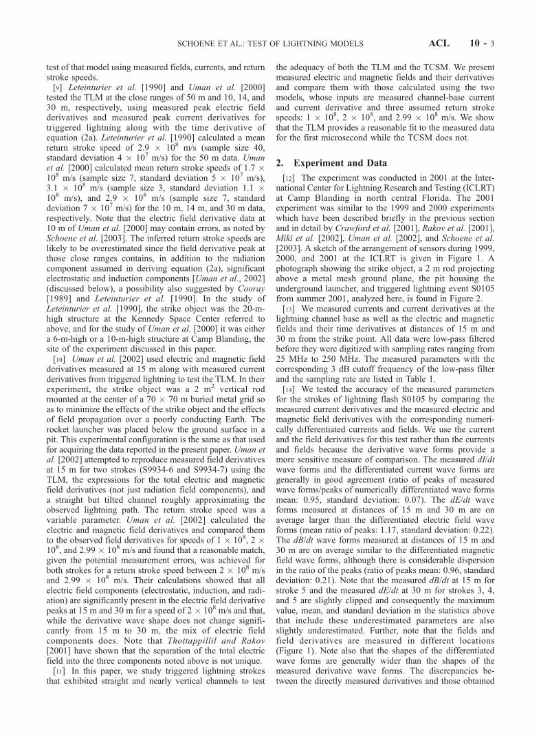
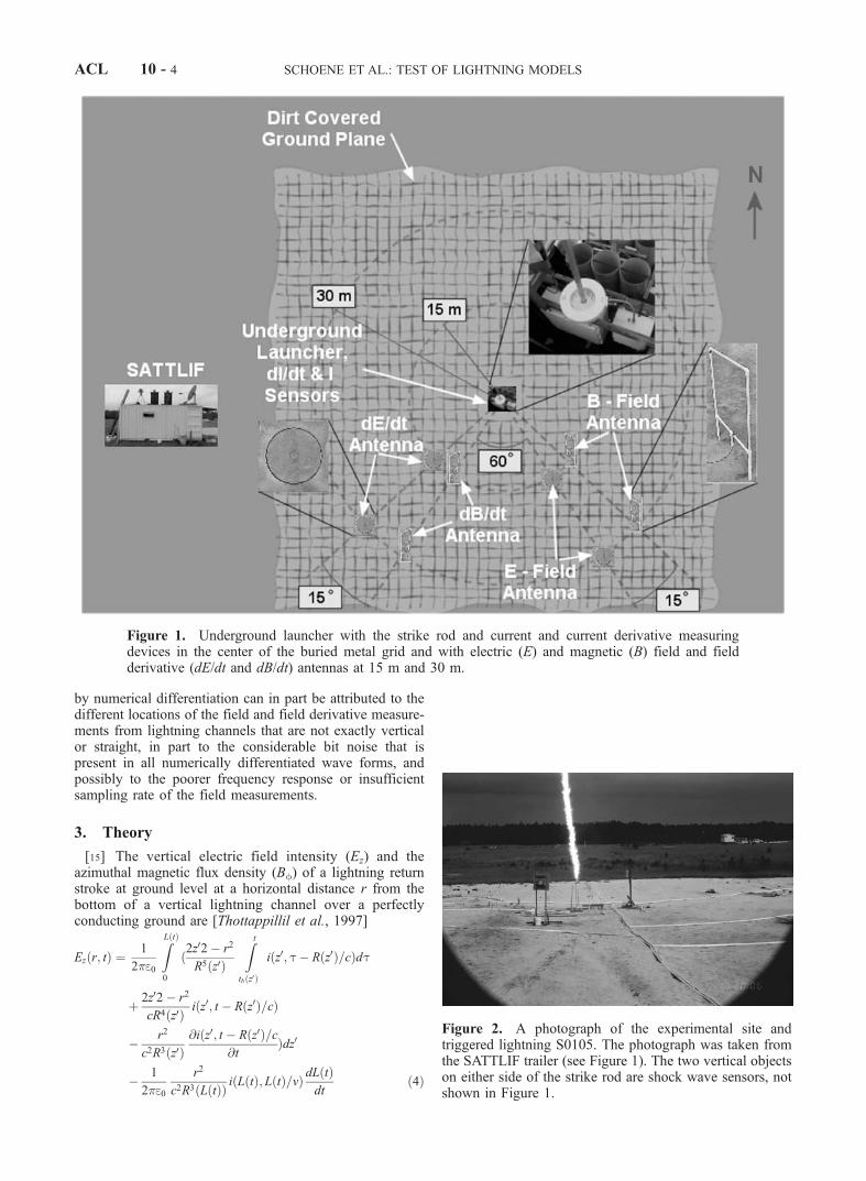
[12] The experiment was conducted in 2001 at the Inter-national Center for Lightning Research and Testing (ICLRT)at Camp Blanding in north central Florida. The 2001experiment was similar to the 1999 and 2000 experimentswhich have been described briefly in the previous sectionand in detail by Crawford et al. [2001], Rakov et al. [2001],Miki et al. [2002], Uman et al. [2002], and Schoene et al.[2003]. A sketch of the arrangement of sensors during 1999,2000, and 2001 at the ICLRT is given in Figure 1. Aphotograph showing the strike object, a 2 m rod projectingabove a metal mesh ground plane, the pit housing theunderground launcher, and triggered lightning event S0105from summer 2001, analyzed here, is found in Figure 2.[13] We measured currents and current derivatives at the
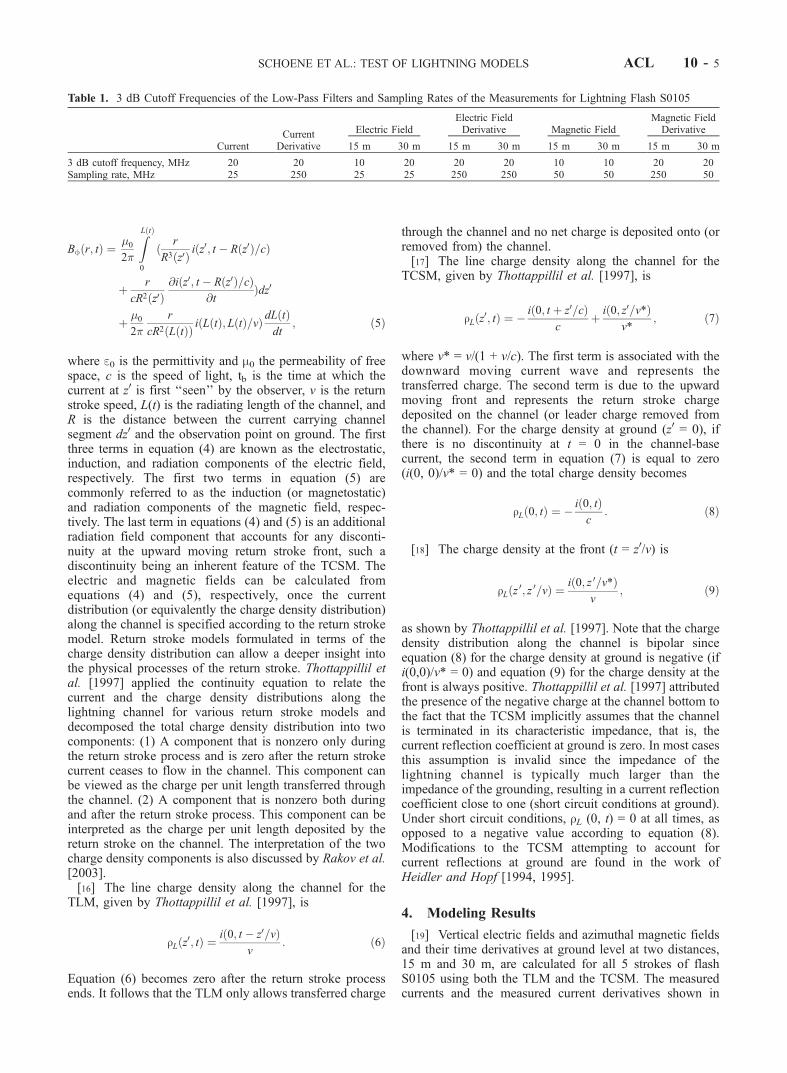
lightning channel base as well as the electric and magneticfields and their time derivatives at distances of 15 m and30 m from the strike point. All data were low-pass filteredbefore they were digitized with sampling rates ranging from25 MHz to 250 MHz. The measured parameters with thecorresponding 3 dB cutoff frequency of the low-pass filterand the sampling rate are listed in Table 1.[14] We tested the accuracy of the measured parameters
for the strokes of lightning flash S0105 by comparing themeasured current derivatives and the measured electric andmagnetic field derivatives with the corresponding numeri-cally differentiated currents and fields. We use the currentand the field derivatives for this test rather than the currentsand fields because the derivative wave forms provide amore sensitive measure of comparison. The measured dI/dtwave forms and the differentiated current wave forms aregenerally in good agreement (ratio of peaks of measuredwave forms/peaks of numerically differentiated wave formsmean: 0.95, standard deviation: 0.07). The dE/dt waveforms measured at distances of 15 m and 30 m are onaverage larger than the differentiated electric field waveforms (mean ratio of peaks: 1.17, standard deviation: 0.22).The dB/dt wave forms measured at distances of 15 m and30 m are on average similar to the differentiated magneticfield wave forms, although there is considerable dispersionin the ratio of the peaks (ratio of peaks mean: 0.96, standarddeviation: 0.21). Note that the measured dB/dt at 15 m forstroke 5 and the measured dE/dt at 30 m for strokes 3, 4,and 5 are slightly clipped and consequently the maximumvalue, mean, and standard deviation in the statistics abovethat include these underestimated parameters are alsoslightly underestimated. Further, note that the fields andfield derivatives are measured in different locations(Figure 1). Note also that the shapes of the differentiatedwave forms are generally wider than the shapes of themeasured derivative wave forms. The discrepancies be-tween the directly measured derivatives and those obtained
SCHOENE ET AL.: TEST OF LIGHTNING MODELS ACL 10 - 3
by numerical differentiation can in part be attributed to thedifferent locations of the field and field derivative measure-ments from lightning channels that are not exactly verticalor straight, in part to the considerable bit noise that ispresent in all numerically differentiated wave forms, andpossibly to the poorer frequency response or insufficientsampling rate of the field measurements.
3. Theory
[15] The vertical electric field intensity (Ez) and theazimuthal magnetic flux density (Bf) of a lightning returnstroke at ground level at a horizontal distance r from thebottom of a vertical lightning channel over a perfectlyconducting ground are [Thottappillil et al., 1997]
Ezðr; tÞ ¼1
2�e0
ZLðtÞ
0
ð2z02� r2
R5ðz0Þ
Z t
tbðz0Þ
iðz0; t� Rðz0Þ=cÞdt
þ 2z02� r2
cR4ðz0Þ iðz0; t � Rðz0Þ=cÞ
� r2
c2R3ðz0Þ@iðz0; t � Rðz0Þ=c
@tÞdz0
� 1
2�e0
r2
c2R3ðLðtÞÞ iðLðtÞ;LðtÞ=vÞdLðtÞdt
ð4Þ
Figure 2. A photograph of the experimental site andtriggered lightning S0105. The photograph was taken fromthe SATTLIF trailer (see Figure 1). The two vertical objectson either side of the strike rod are shock wave sensors, notshown in Figure 1.
Figure 1. Underground launcher with the strike rod and current and current derivative measuringdevices in the center of the buried metal grid and with electric (E) and magnetic (B) field and fieldderivative (dE/dt and dB/dt) antennas at 15 m and 30 m.
ACL 10 - 4 SCHOENE ET AL.: TEST OF LIGHTNING MODELS
Bfðr; tÞ ¼�0
2�
ZLðtÞ
0
ð r
R3ðz0Þ iðz0; t � Rðz0Þ=cÞ
þ r
cR2ðz0Þ@iðz0; t � Rðz0Þ=cÞ
@tÞdz0
þ �0
2�
r
cR2ðLðtÞÞ iðLðtÞ;LðtÞ=vÞdLðtÞdt
; ð5Þ
where e0 is the permittivity and m0 the permeability of freespace, c is the speed of light, tb is the time at which thecurrent at z0 is first ‘‘seen’’ by the observer, v is the returnstroke speed, L(t) is the radiating length of the channel, andR is the distance between the current carrying channelsegment dz0 and the observation point on ground. The firstthree terms in equation (4) are known as the electrostatic,induction, and radiation components of the electric field,respectively. The first two terms in equation (5) arecommonly referred to as the induction (or magnetostatic)and radiation components of the magnetic field, respec-tively. The last term in equations (4) and (5) is an additionalradiation field component that accounts for any disconti-nuity at the upward moving return stroke front, such adiscontinuity being an inherent feature of the TCSM. Theelectric and magnetic fields can be calculated fromequations (4) and (5), respectively, once the currentdistribution (or equivalently the charge density distribution)along the channel is specified according to the return strokemodel. Return stroke models formulated in terms of thecharge density distribution can allow a deeper insight intothe physical processes of the return stroke. Thottappillil etal. [1997] applied the continuity equation to relate thecurrent and the charge density distributions along thelightning channel for various return stroke models anddecomposed the total charge density distribution into twocomponents: (1) A component that is nonzero only duringthe return stroke process and is zero after the return strokecurrent ceases to flow in the channel. This component canbe viewed as the charge per unit length transferred throughthe channel. (2) A component that is nonzero both duringand after the return stroke process. This component can beinterpreted as the charge per unit length deposited by thereturn stroke on the channel. The interpretation of the twocharge density components is also discussed by Rakov et al.[2003].[16] The line charge density along the channel for the
TLM, given by Thottappillil et al. [1997], is
rLðz0; tÞ ¼ið0; t � z0=vÞ
v: ð6Þ
Equation (6) becomes zero after the return stroke processends. It follows that the TLM only allows transferred charge
through the channel and no net charge is deposited onto (orremoved from) the channel.[17] The line charge density along the channel for the
TCSM, given by Thottappillil et al. [1997], is
rLðz0; tÞ ¼ � ið0; t þ z0=cÞc
þ ið0; z0=v*Þv*
; ð7Þ
where v* = v/(1 + v/c). The first term is associated with thedownward moving current wave and represents thetransferred charge. The second term is due to the upwardmoving front and represents the return stroke chargedeposited on the channel (or leader charge removed fromthe channel). For the charge density at ground (z0 = 0), ifthere is no discontinuity at t = 0 in the channel-basecurrent, the second term in equation (7) is equal to zero(i(0, 0)/v* = 0) and the total charge density becomes
rLð0; tÞ ¼ � ið0; tÞc
: ð8Þ
[18] The charge density at the front (t = z0/v) is
rLðz 0; z 0=vÞ ¼ið0; z 0=v*Þ
v; ð9Þ
as shown by Thottappillil et al. [1997]. Note that the chargedensity distribution along the channel is bipolar sinceequation (8) for the charge density at ground is negative (ifi(0,0)/v* = 0) and equation (9) for the charge density at thefront is always positive. Thottappillil et al. [1997] attributedthe presence of the negative charge at the channel bottom tothe fact that the TCSM implicitly assumes that the channelis terminated in its characteristic impedance, that is, thecurrent reflection coefficient at ground is zero. In most casesthis assumption is invalid since the impedance of thelightning channel is typically much larger than theimpedance of the grounding, resulting in a current reflectioncoefficient close to one (short circuit conditions at ground).Under short circuit conditions, rL (0, t) = 0 at all times, asopposed to a negative value according to equation (8).Modifications to the TCSM attempting to account forcurrent reflections at ground are found in the work ofHeidler and Hopf [1994, 1995].
4. Modeling Results
[19] Vertical electric fields and azimuthal magnetic fieldsand their time derivatives at ground level at two distances,15 m and 30 m, are calculated for all 5 strokes of flashS0105 using both the TLM and the TCSM. The measuredcurrents and the measured current derivatives shown in
Table 1. 3 dB Cutoff Frequencies of the Low-Pass Filters and Sampling Rates of the Measurements for Lightning Flash S0105
CurrentCurrent
Derivative
Electric FieldElectric FieldDerivative Magnetic Field
Magnetic FieldDerivative
15 m 30 m 15 m 30 m 15 m 30 m 15 m 30 m
3 dB cutoff frequency, MHz 20 20 10 20 20 20 10 10 20 20Sampling rate, MHz 25 250 25 25 250 250 50 50 250 50
SCHOENE ET AL.: TEST OF LIGHTNING MODELS ACL 10 - 5
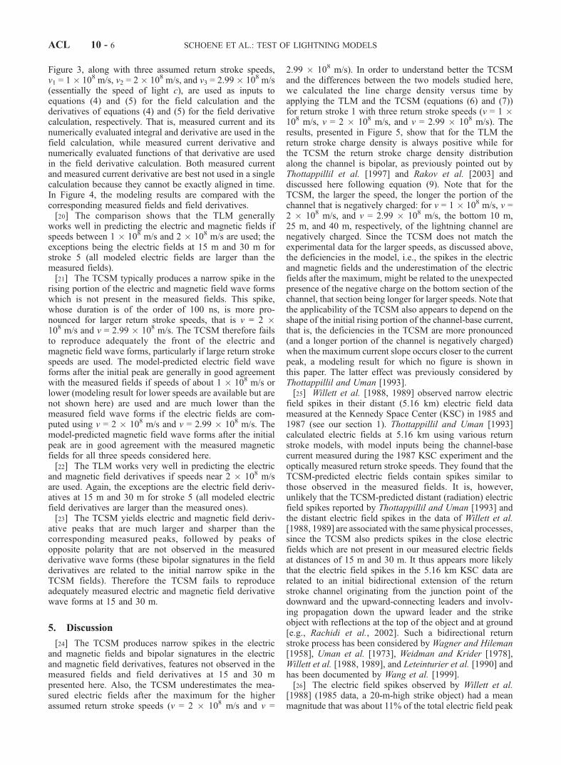
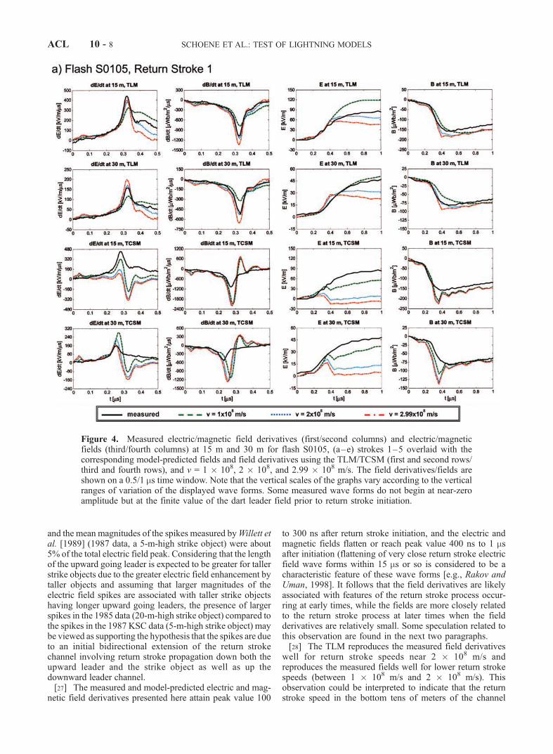
Figure 3, along with three assumed return stroke speeds,v1 = 1 � 108 m/s, v2 = 2 � 108 m/s, and v3 = 2.99 � 108 m/s(essentially the speed of light c), are used as inputs toequations (4) and (5) for the field calculation and thederivatives of equations (4) and (5) for the field derivativecalculation, respectively. That is, measured current and itsnumerically evaluated integral and derivative are used in thefield calculation, while measured current derivative andnumerically evaluated functions of that derivative are usedin the field derivative calculation. Both measured currentand measured current derivative are best not used in a singlecalculation because they cannot be exactly aligned in time.In Figure 4, the modeling results are compared with thecorresponding measured fields and field derivatives.[20] The comparison shows that the TLM generally
works well in predicting the electric and magnetic fields ifspeeds between 1 � 108 m/s and 2 � 108 m/s are used; theexceptions being the electric fields at 15 m and 30 m forstroke 5 (all modeled electric fields are larger than themeasured fields).[21] The TCSM typically produces a narrow spike in the
rising portion of the electric and magnetic field wave formswhich is not present in the measured fields. This spike,whose duration is of the order of 100 ns, is more pro-nounced for larger return stroke speeds, that is v = 2 �108 m/s and v = 2.99 � 108 m/s. The TCSM therefore failsto reproduce adequately the front of the electric andmagnetic field wave forms, particularly if large return strokespeeds are used. The model-predicted electric field waveforms after the initial peak are generally in good agreementwith the measured fields if speeds of about 1 � 108 m/s orlower (modeling result for lower speeds are available but arenot shown here) are used and are much lower than themeasured field wave forms if the electric fields are com-puted using v = 2 � 108 m/s and v = 2.99 � 108 m/s. Themodel-predicted magnetic field wave forms after the initialpeak are in good agreement with the measured magneticfields for all three speeds considered here.[22] The TLM works very well in predicting the electric
and magnetic field derivatives if speeds near 2 � 108 m/sare used. Again, the exceptions are the electric field deriv-atives at 15 m and 30 m for stroke 5 (all modeled electricfield derivatives are larger than the measured ones).[23] The TCSM yields electric and magnetic field deriv-
ative peaks that are much larger and sharper than thecorresponding measured peaks, followed by peaks ofopposite polarity that are not observed in the measuredderivative wave forms (these bipolar signatures in the fieldderivatives are related to the initial narrow spike in theTCSM fields). Therefore the TCSM fails to reproduceadequately measured electric and magnetic field derivativewave forms at 15 and 30 m.
5. Discussion
[24] The TCSM produces narrow spikes in the electricand magnetic fields and bipolar signatures in the electricand magnetic field derivatives, features not observed in themeasured fields and field derivatives at 15 and 30 mpresented here. Also, the TCSM underestimates the mea-sured electric fields after the maximum for the higherassumed return stroke speeds (v = 2 � 108 m/s and v =
2.99 � 108 m/s). In order to understand better the TCSMand the differences between the two models studied here,we calculated the line charge density versus time byapplying the TLM and the TCSM (equations (6) and (7))for return stroke 1 with three return stroke speeds (v = 1 �108 m/s, v = 2 � 108 m/s, and v = 2.99 � 108 m/s). Theresults, presented in Figure 5, show that for the TLM thereturn stroke charge density is always positive while forthe TCSM the return stroke charge density distributionalong the channel is bipolar, as previously pointed out byThottappillil et al. [1997] and Rakov et al. [2003] anddiscussed here following equation (9). Note that for theTCSM, the larger the speed, the longer the portion of thechannel that is negatively charged: for v = 1 � 108 m/s, v =2 � 108 m/s, and v = 2.99 � 108 m/s, the bottom 10 m,25 m, and 40 m, respectively, of the lightning channel arenegatively charged. Since the TCSM does not match theexperimental data for the larger speeds, as discussed above,the deficiencies in the model, i.e., the spikes in the electricand magnetic fields and the underestimation of the electricfields after the maximum, might be related to the unexpectedpresence of the negative charge on the bottom section of thechannel, that section being longer for larger speeds. Note thatthe applicability of the TCSM also appears to depend on theshape of the initial rising portion of the channel-base current,that is, the deficiencies in the TCSM are more pronounced(and a longer portion of the channel is negatively charged)when the maximum current slope occurs closer to the currentpeak, a modeling result for which no figure is shown inthis paper. The latter effect was previously considered byThottappillil and Uman [1993].[25] Willett et al. [1988, 1989] observed narrow electric
field spikes in their distant (5.16 km) electric field datameasured at the Kennedy Space Center (KSC) in 1985 and1987 (see our section 1). Thottappillil and Uman [1993]calculated electric fields at 5.16 km using various returnstroke models, with model inputs being the channel-basecurrent measured during the 1987 KSC experiment and theoptically measured return stroke speeds. They found that theTCSM-predicted electric fields contain spikes similar tothose observed in the measured fields. It is, however,unlikely that the TCSM-predicted distant (radiation) electricfield spikes reported by Thottappillil and Uman [1993] andthe distant electric field spikes in the data of Willett et al.[1988, 1989] are associated with the same physical processes,since the TCSM also predicts spikes in the close electricfields which are not present in our measured electric fieldsat distances of 15 m and 30 m. It thus appears more likelythat the electric field spikes in the 5.16 km KSC data arerelated to an initial bidirectional extension of the returnstroke channel originating from the junction point of thedownward and the upward-connecting leaders and involv-ing propagation down the upward leader and the strikeobject with reflections at the top of the object and at ground[e.g., Rachidi et al., 2002]. Such a bidirectional returnstroke process has been considered by Wagner and Hileman[1958], Uman et al. [1973], Weidman and Krider [1978],Willett et al. [1988, 1989], and Leteinturier et al. [1990] andhas been documented by Wang et al. [1999].[26] The electric field spikes observed by Willett et al.
[1988] (1985 data, a 20-m-high strike object) had a meanmagnitude that was about 11% of the total electric field peak
ACL 10 - 6 SCHOENE ET AL.: TEST OF LIGHTNING MODELS

Figure 3. Measured (left) current derivatives and (right) currents of five return strokes in flash S0105.Current derivatives are shown on a 0.5-ms timescale, and currents are shown on a 5-ms timescale.
SCHOENE ET AL.: TEST OF LIGHTNING MODELS ACL 10 - 7
and the mean magnitudes of the spikes measured byWillett etal. [1989] (1987 data, a 5-m-high strike object) were about5% of the total electric field peak. Considering that the lengthof the upward going leader is expected to be greater for tallerstrike objects due to the greater electric field enhancement bytaller objects and assuming that larger magnitudes of theelectric field spikes are associated with taller strike objectshaving longer upward going leaders, the presence of largerspikes in the 1985 data (20-m-high strike object) compared tothe spikes in the 1987 KSC data (5-m-high strike object) maybe viewed as supporting the hypothesis that the spikes are dueto an initial bidirectional extension of the return strokechannel involving return stroke propagation down both theupward leader and the strike object as well as up thedownward leader channel.[27] The measured and model-predicted electric and mag-
netic field derivatives presented here attain peak value 100
to 300 ns after return stroke initiation, and the electric andmagnetic fields flatten or reach peak value 400 ns to 1 msafter initiation (flattening of very close return stroke electricfield wave forms within 15 ms or so is considered to be acharacteristic feature of these wave forms [e.g., Rakov andUman, 1998]. It follows that the field derivatives are likelyassociated with features of the return stroke process occur-ring at early times, while the fields are more closely relatedto the return stroke process at later times when the fieldderivatives are relatively small. Some speculation related tothis observation are found in the next two paragraphs.[28] The TLM reproduces the measured field derivatives
well for return stroke speeds near 2 � 108 m/s andreproduces the measured fields well for lower return strokespeeds (between 1 � 108 m/s and 2 � 108 m/s). Thisobservation could be interpreted to indicate that the returnstroke speed in the bottom tens of meters of the channel
Figure 4. Measured electric/magnetic field derivatives (first/second columns) and electric/magneticfields (third/fourth columns) at 15 m and 30 m for flash S0105, (a–e) strokes 1–5 overlaid with thecorresponding model-predicted fields and field derivatives using the TLM/TCSM (first and second rows/third and fourth rows), and v = 1 � 108, 2 � 108, and 2.99 � 108 m/s. The field derivatives/fields areshown on a 0.5/1 ms time window. Note that the vertical scales of the graphs vary according to the verticalranges of variation of the displayed wave forms. Some measured wave forms do not begin at near-zeroamplitude but at the finite value of the dart leader field prior to return stroke initiation.
ACL 10 - 8 SCHOENE ET AL.: TEST OF LIGHTNING MODELS

decreases rapidly with height, although, strictly speaking,the model is not valid for a time-varying return strokespeed. Also, the bottom 10 m or so may involve an upwardconnecting leader [Wang et al., 1999], not considered in themodel.[29] For strokes 1, 2, 3, and 4, the TLM with a return
stroke speed close to 2 � 108 m/s gives the best overallmatch between measured and model-predicted electric andmagnetic field derivatives. A speed that gives the bestoverall match for the electric fields of these four strokescannot be found. One of the possible, admittedly specula-tive, interpretations of this result is that there is lessvariation in return stroke speeds between strokes at earlytimes when the return stroke front is within some tens ofmeters of the channel bottom than there is for return strokespeeds at later times. Again, strictly speaking, the modeldoes not allow this inference.[30] There are various modification of the TLM that
allow a current decay with height and hence a depositedcharge on the channel (e.g., the modified transmission linemodel with linear current decay with height [Rakov andDulzon, 1987] and the modified transmission line modelwith exponential current decay with height [Nucci et al.,
1988]). For the first 1 ms of the return stroke modeled in thepresent paper, the results obtained here are essentially thesame as would be obtained during the first 1 ms using thosemodified TL-type models since the current versus heightprofile is essentially the same for the different TL-typemodels for the first microsecond. As noted in section 3, theTCSM can be modified to take account of current reflec-tions at ground. Potentially, this modification might alter thebipolar nature of the TCSM charge distribution discussedabove and in section 3 with the resultant TCSM wave formsbeing possibly different from those presented here.
6. Concluding Remarks
[31] The TLM works reasonably well in reproducingclose measured electric and magnetic fields if return strokespeeds during the first microsecond are chosen to bebetween 1 � 108 m/s and 2 � 108 m/s, and works well inreproducing field derivatives for return stroke speeds near2 � 108 m/s. This result is very similar to that of Willett etal. [1989] (see section 1) obtained from measurementsof radiation (far) fields at 5.16 km whereas the presentestimation of return stroke speed involves close field wave
Figure 4. (continued)
SCHOENE ET AL.: TEST OF LIGHTNING MODELS ACL 10 - 9

Figure 4. (continued)
ACL 10 - 10 SCHOENE ET AL.: TEST OF LIGHTNING MODELS
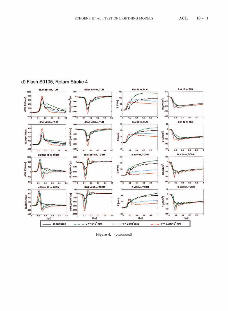
Figure 4. (continued)
SCHOENE ET AL.: TEST OF LIGHTNING MODELS ACL 10 - 11

Figure 4. (continued)
ACL 10 - 12 SCHOENE ET AL.: TEST OF LIGHTNING MODELS

forms (at 15 and 30 m) that contain significant, if notdominant, near-field components [Uman et al., 2002]. TheTCSM is deficient in modeling the 15 and 30 m fields,probably because it predicts a negative charge density at andnear the channel bottom that is apparently related to theunrealistic assumption of matched conditions at the groundfor the downward propagating current wave, while shortcircuit conditions are expected in most practical situations.The effect is more pronounced for higher return strokespeeds and for current wave forms with a maximum currentrate of rise close to the current peak. Modifications to theTCSM related to the channel termination on ground shouldbe considered to determine if such modification wouldimprove the agreement with measurements. Further, othertraveling current source type models such as the Diendorfer-Uman model [Diendorfer and Uman, 1990] should betested against experimental data. Such additional modelingwill be the subject of a future paper.
[32] Acknowledgments. This research was supported in part by DOT(FAA) Grant 99-G-043 and NSF Grant ATM-0003994.
ReferencesCooray, V., Derivation of return stroke parameters from the electric andmagnetic field derivatives, Geophys. Res. Lett., 16, 61–64, 1989.
Crawford, D. E., V. A. Rakov, M. A. Uman, G. H. Schnetzer, K. J. Rambo,M. V. Stapleton, and R. J. Fisher, The close lightning electromagneticenvironment: Dart-leader electric field change versus distance, J. Geo-phys. Res., 106, 14,909–14,917, 2001.
Dennis, A. S., and E. T. Pierce, The return stroke of the lightning flash toEarth as a source of VLF atmospherics, Radio Sci., 68D, 777–794, 1964.
Diendorfer, G., and M. A. Uman, An improved return stroke model withspecified channel-based current, J. Geophys. Res., 95, 13,621–13,644,1990.
Heidler, F., Traveling current source model for LEMP calculation, paperpresented at the 6th International Symposium on Electromagnetic Com-patibility, Swiss Fed. Inst. of Technol., Zurich, Switzerland, March 1985.
Heidler, F., and C. Hopf, Lightning current and lightning electromagneticimpulse considering current reflection at the Earth’s surface, paper pre-sented at the 22nd International Conference on Lightning Protection,paper R 4-05, Tech. Univ. of Budapest, Budapest, Hungary, 1994.
Heidler, F., and C. Hopf, Influence of channel-base current and currentreflections on the initial and subsidiary lightning electromagnetic fieldpeak, paper presented at the International Aerospace and Ground Con-ference on Lightning and Static Electricity, Natl. Interagency Coord.Group, Williamsburg, Va., 1995.
Krider, E. P., C. Leteinturier, and J. C. Willett, Submicrosecond fieldsradiated during the onset of first return strokes in cloud-to-ground light-ning, J. Geophys. Res., 101, 1589–1597, 1996.
Leteinturier, C., C. Weidman, and J. Hamelin, Current and electric fieldderivatives in triggered lightning return strokes, J. Geophys. Res., 95,811–828, 1990.
Miki, M., V. A. Rakov, K. J. Rambo, G. H. Schnetzer, and M. A. Uman,Electric fields near triggered lightning channels measured with Pockelssensors, J. Geophys. Res., 107(D16), 4277, doi:10.1029/2001JD001087,2002.
Nucci, C. A., C. Mazzetti, F. Rachidi, and M. Ianoz, On lightning returnstroke models for LEMP calculations, paper presented at the 19th Inter-national Conference on Lightning Protection, OVE, Graz, Austria, April1988.
Rachidi, F., V. A. Rakov, C. A. Nucci, and J. L. Bermudez, The effect ofvertically extended strike object on the distribution of current along thelightning channel, J. Geophys. Res., 107(D23), 4699, doi:10.1029/2002JD002119, 2002.
Rakov, V. A., and A. A. Dulzon, Calculated electromagnetic fields of light-ning return stroke, Tekh. Elekrodinam., 1, 87–89, 1987.
Rakov, V. A., and M. A. Uman, Review and evaluation of lightning returnstroke models including some aspects of their application, IEEE Trans.Electromagn. Compat., 40, 403–426, 1998.
Figure 5. Line charge densities associated with the return stroke process versus channel height z0 aboveground at 1 ms for stroke 1 of flash S0105 calculated using (a) the TCSM and (b) the TLM. Note that forthe TLM the total charge density is equal to the transferred charge density. Note that the total return strokecharge density distribution for the TLM is unipolar, while for the TCSM it is bipolar.
SCHOENE ET AL.: TEST OF LIGHTNING MODELS ACL 10 - 13

Rakov, V. A., D. E. Crawford, K. J. Rambo, G. H. Schnetzer, M. A. Uman,and R. Thottappillil, M-component mode of charge transfer to ground inlightning discharges, J. Geophys. Res., 106, 22,817–22,831, 2001.
Rakov, V. A., R. Thottappillil, and J. Schoene, Comments on ‘‘On the IEEETrans Electromagn. Compat., concepts used in return stroke modelsapplied in engineering practice,’’ 45, 567, 2003.
Schoene, J., M. A. Uman, V. A. Rakov, V. Kodali, K. J. Rambo, and G. H.Schnetzer, Statistical characteristics of the electric and magnetic fieldsand their time derivatives 15 m and 30 m from triggered lightning,J. Geophys. Res., 108(D6), 4192, doi:10.1029/2002JD002698, 2003.
Thottappillil, R., and V. A. Rakov, On different approaches to calculatinglightning electric fields, J. Geophys. Res., 106, 14,191–14,205, 2001.
Thottappillil, R., and M. A. Uman, Comparison of lightning return-strokemodels, J. Geophys. Res., 98, 22,903–22,914, 1993.
Thottappillil, R., V. A. Rakov, and M. A. Uman, Distribution of chargealong the lightning channel: Relation to remote electric and magneticfields and to return-stroke models, J. Geophys. Res., 102, 6987–7006,1997.
Uman, M. A., and D. K. McLain, Magnetic field of lightning return stroke,J. Geophys. Res., 74, 6899–6910, 1969.
Uman, M. A., and D. K. McLain, Lightning return stroke current frommagnetic and radiation field measurements, J. Geophys. Res., 75,5143–5147, 1970.
Uman, M. A., D. K. McLain, R. J. Fisher, and E. P. Krider, Currentsin Florida lightning return strokes, J. Geophys. Res., 78, 3530–3537,1973.
Uman, M. A., D. K. McLain, and E. P. Krider, The electromagnetic radia-tion from a finite antenna, Am. J. Phys., 43, 33–38, 1975.
Uman, M. A., V. A. Rakov, G. H. Schnetzer, K. J. Rambo, D. E. Crawford,and R. J. Fisher, Time derivative of the electric field 10, 14, and 30 mfrom triggered lightning strokes, J. Geophys. Res., 105, 15,577–15,595,2000.
Uman, M. A., J. Schoene, V. A. Rakov, K. J. Rambo, and G. H. Schnetzer,Correlated time derivatives of current, electric field intensity, and mag-netic flux density for triggered lightning at 15 m, J. Geophys. Res.,107(D13), 4160, doi:10.1029/2000JD000249, 2002.
Wagner, C. F., Determination of the wave front of lightning stroke currentsfrom field measurements, Trans. Am. Inst. Electron. Eng., Part 3, 79,581–589, 1960.
Wagner, C. F., and A. R. Hileman, The lightning stroke, Trans Am. Inst.Electron. Eng., Part 3, 77, 229–242, 1958.
Wang, D., V. A. Rakov, M. A. Uman, N. Takagi, T. Watanabe, D. E.Crawford, K. J. Rambo, G. H. Schnetzer, R. J. Fisher, and Z. I. Kawasaki,Attachment process in rocket-triggered lightning strokes, J. Geophys.Res., 104, 2143–2150, 1999.
Weidman, C. D., and E. P. Krider, The fine structure of lightning returnstroke wave forms, J. Geophys. Res., 83, 6239–6247, 1978.
Weidman, C. D., and E. P. Krider, Submicrosecond risetimes in lightningreturn-stroke fields, Geophys. Res. Lett., 7, 955–958, 1980.
Willett, J. C., V. P. Idone, R. E. Orville, C. Leteinturier, A. Eybert-Berard,L. Barret, and E. P. Krider, An experimental test of the ‘‘transmission-linemodel’’ of the electromagnetic radiation from triggered lightning returnstrokes, J. Geophys. Res., 93, 3867–3878, 1988.
Willett, J. C., J. C. Bailey, V. P. Idone, A. Eybert-Berard, and L. Barret,Submicrosecond intercomparison of radiation fields and currents intriggered lightning return strokes based on the ‘‘transmission-linemodel,’’J. Geophys. Res., 94, 13,275–13,286, 1989.
�����������������������J. Jerauld, V. A. Rakov, K. J. Rambo, G. H. Schnetzer, J. Schoene, and
M. A. Uman, Department of Electrical and Computer Engineering,University of Florida, 311 Larsen Hall, Gainesville, FL 32611, USA.( [email protected]; [email protected]; [email protected]; [email protected]; [email protected]; [email protected])
ACL 10 - 14 SCHOENE ET AL.: TEST OF LIGHTNING MODELS