Embed Size (px)
Citation preview
FAA Technical Center Atlantic City International Airport N.J. 08405
Test Methods for Composites
Volume III. Shear Test
U.S. Department of Transportation Federal Aviation Administration
NOTICE
This document is disseminated under the sponsorship of the U. S. Department of Transportation in the interest of information exchange. The United States Government assumes no liability for the contents or use thereof.
The United States Government does not endorse products or manufacturers. Trade or manufacturers' names appear herein solely because they are considered essential to the objective of this report.
Technical Report Documentation Page
DOTIFAAICT-93/17, *I11 I 4. T i t l e and Subtit le
1. Report No.
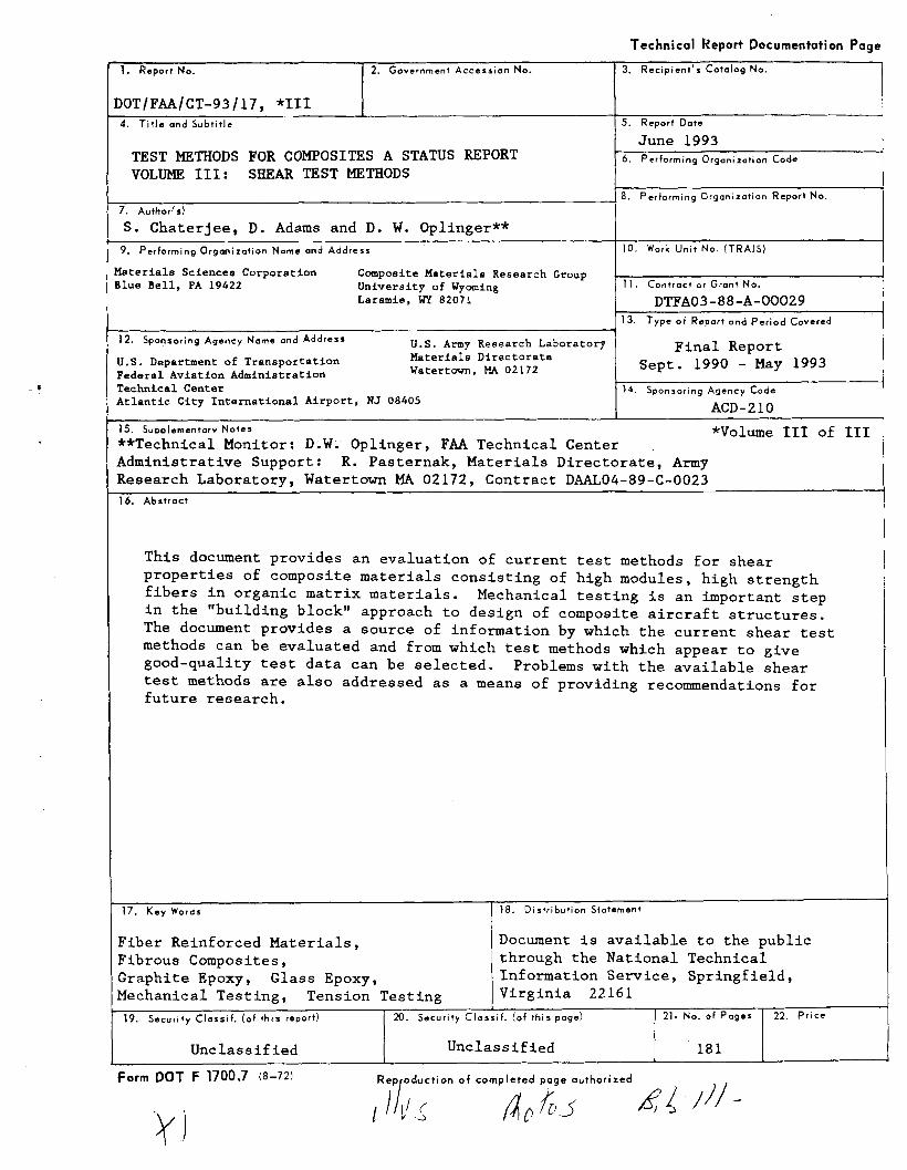
TEST METHODS FOR COMPOSITES A STATUS REPORT VOLUME 111: SHEAR TEST METHODS
2. Government Accession No.
7. author!^)
S. Chaterjee, D. Adarns and D. W. Oplinger** 9. Performing Organization Name and Address
faterials Sciences Corporation Composite Materials Research Group llue Bell, PA 19422 University of Wyoming
Laramie. WY 82071
12. Sponsoring Agency Name and Address U.S. Army Research Laboratory
U.S. Department of Transportation Materials Directorate
Federal Aviation Administration Watertavn. HA 02172
Pechnical Center Atlantic City International Airport, NJ 08405
15. S u ~ n l e m e n t a r v N o t e s
3. Recip ient 's Cotalog No.
5. Report Date
June 1993 6 . Performing Organization Code
- 8. Pertorming Organization Report N O .
101 Work ~ n i t ~ ~ o . ( T R A I S )
11. Contract or Grant N o .
DTFA03-88-A-00029 13. Type o f Rapart and P e r i o d Covered
Final Report Sept. 1990 - May 1993
14. Sponsoring Agency Code
ACD-210
*Volume 111 of 111 **Technical Monitor: D.W. Oplinger, FAA Technical Center Administrative Support: R. Pasternak, Materials Directorate, Army Research Laboratory, Watertown MA 02172, Contract DAAL04-89-C-0023 16. Abstract
This document provides an evaluation of current test methods for shear properties of composite materials consisting of high modules, high strength fibers in organic matrix materials. Mechanical testing is an important step in the "building block" approach to design of composite aircraft structures. The document provides a source of information by which the current shear test methods can be evaluated and from which test methods which appear to give good-quality test data can be selected. Problems with the available shear test methods are also addressed as a means of providing recommendations for future research.
17. K e y Words
Fiber Reinforced Materials, Fibrous Composites, Graphite Epoxy, Glass Epoxy, Mechanical Testing, Tension Testing
Form DOT F 1700.7 (8-721
18. Distribution Statement
Document is available to the public through the National Technical Information Service, Springfield, Virginia 22161
Unclassified
o f c o m p l e t e d page a u t h o r i z e d
19. Security Classi f . (of this report) 1 20. Security Classi f . (o f this 21. No. of P a g e s
Unclassified
22. P r i c e
18 1

PREFACE
This document is Volume I11 of three volumes which have been developed to provide
an assessment of mechanical property test methods for organic matrix composite materials.
The present volume presents a review and evaluation of test methods for shear properties of
fiber reinforced composite materials. Two companion documents, Volume I on Tension Test
Methods and Volume I1 on Compression Test Methods, have also been prepared.
This document was developed under an Interagency Agreement between the Federal
Aviation Administration Technical Center, Atlantic City International Airport, NJ and the
U.S. Army Research Laboratory Materials Directorate, Watertown MA. Technical Direction
was provided by D. W. Oplinger of the Federal Aviation Administration Technical Center
with the advice of J. Soderquist, FAA Headquarters, Washington DC, while administrative
support was provided by R. Pasternak of the Army Research Laboratory Materials
Directorate. The work was performed under contract to Materials Sciences Corporation and
the Composite Materials Research Group, University of Wyoming. Principal Investigator was
Dr. S. Chaterjee of Materials Sciences Corporation with direction of the University of
Wyoming effort by Prof. D. Adams.

TABLE OF CONTENTS
PAG E
PREFACE ............................................................................................................ .......................................................................................... TABLE OF CONTENTS
................................................................................................... LIST OF TABLES
................................................................................................. LIST OF FIGURES
EXECUTIVE SUMMARY ............................. .. ......................................................... OVERVIEW ..........................................................................................................
........................................................................................ GENERAL REMARKS
OBSERVATIONS ON MECHANICAL PROPERTY TESTING OF COMPOSITES ............
FACTORS AFFECTING PERFORMANCE OF TEST SPECIMENS ............................... .......................................................................... FORMAT OF THE DOCUMENT
TECHNICAL SUMMARY ...................................................................................... INPLANE SHEAR .................................................................................................. INTERLAMINAR SHEAR ........................................................................................ 1 . INTRODUCTION .............................................................................................. 2 . SUMMARY AND RECOMMENDATIONS ..............................................................
2.1 TORSION TUBE ......................................................................................... 2.2 TORSION OF SOLID CIRCULAR BAR ...........................................................
.................................................... 2.3 TORSION OF SOLID RECTANGULAR BAR
...................................................................................... 2.4 ( + 45O),, TENSION
2.5 IOSIPESCU ............................................................................................... 2.6 ARCAN ..................................................................................................... 2.7 RAIL SHEAR ............................................................................................ 2.8 OFF-AXIS TENSION ............................ ... ................................................ 2.9 PICTURE FRAME ......................................................................................
................................................. 2.10 CROSS BEAM OR CRUCIFORM SPECIMEN
2.1 1 SLOTTED SHEAR ............................ ... ................................................... 2.1 2 SHORT BEAM SHEAR ..................... .. ......................................................
....................................................................................... 2.1 3 OTHER TESTS
............................................. ............................ 2.1 4 RECOMMENDATIONS ..

3 . DETAILED DISCUSSIONS . . . . . . . . . . . . . . . . . . . . . . . . . . . . . . . . . . . . . . . . 29
3.1TORSlONTUBE . . . . . . . . . . . . . . . . . . . . . . . . . . . . . . . . . . . . . . . . . . . . 29
3.2 TORSION OF CIRCULAR BAR . . . . . . . . . . . . . . . . . . . . . . . . . . . . . . . . . . . 35
3.3 TORSION OF RECTANGULAR BAR . . . . . . . . . . . . . . . . . . . . . . . . . . . . . . . 4 0
3.4 (*45O),, TENSION . . . . . . . . . . . . . . . . . . . . . . . . . . . . . . . . . . . . . . . . 47
3.5 IOSIPESCU AND APFB . . . . . . . . . . . . . . . . . . . . . . . . . . . . . . . . . . . . . . . . 5 4
3.6ARCAN . . . . . . . . . . . . . . . . . . . . . . . . . . . . . . . . . . . . . . . . . . . . . . . . . . 65
3.7RAlLSHEAR . . . . . . . . . . . . . . . . . . . . . . . . . . . . . . . . . . . . . . . . . . . . . . . 69
3.8 OFF-AXIS TENSION . . . . . . . . . . . . . . . . . . . . . . . . . . . . . . . . . . . . . . . . . . 7 9
3.9PlCTUREFRAMESHEAR . . . . . . . . . . . . . . . . . . . . . . . . . . . . . . . . . . . . . . 8 2
3.10 CROSS BEAM AND CRUCIFORM SPECIMEN . . . . . . . . . . . . . . . . . . . . . . . 8 7
3.1 1 SLOTTED OR NOTCHED SHEAR . . . . . . . . . . . . . . . . . . . . . . . . . . . . . . . . 9 4
3.12SHORTBEAMSHEAR . . . . . . . . . . . . . . . . . . . . . . . . . . . . . . . . . . . . . . . 9 7
3.13OTHERTESTS . . . . . . . . . . . . . . . . . . . . . . . . . . . . . . . . . . . . . . . . . . . 1 0 3
REFERENCES . . . . . . . . . . . . . . . . . . . . . . . . . . . . . . . . . . . . . . . . . . . . . . . . . . 111
APPENDIX . ANNOTATED BIBLIOGRAPHY . . . . . . . . . . . . . . . . . . . . . . . . . . . . . . A-1
LIST OF TABLES
TABLE
1 . Status of lnplane Shear Test Methods . . . . . . . . . . . . . . . . . . .
2 . Status of Interlaminar Shear Test Methods . . . . . . . . . . . . . . . . . . . . . 1 2
3 . Shear Stress-Strain Curve from Nonlinear Torsion Test . . . . . . . . . . . . . . . . . . . . . . . . . . . . . . . . . . . . . . . . . . . . D a t a [ l l ] 39
LIST OF FIGURES
Pane
FIGURE
Torsion Tube Test Specimen Shown w i th Strain Gage Configuration [ I 1 . . . . . . . . . . . . . . . . . . . . . . . . . . . . . . . . . . . . . . . 3 0
. . . . . . . . . . . . . . . . SpecimenlFixture Assembly for Torsion Tube [ I I 3 1
Normalized Stresses Along the Inner and Outer Radii for Torsion Tests [51 . . . . . . . . . . . . . . . . . . . . . . . . . . . . . . . . . . . . . . . . . . . . 3 2
Failure Modes for Hoop Wound Tubes in lnplane Shear [ I I . . . . . . . . . . 3 4
Circular Cross-Section Torsion Specimens . . . . . . . . . . . . . . . . . . . . . 3 6
Representative Data from Difference lnplane Shear Tests on Unidirectional AS413501 -6 Specimens [ I 1 I . . . . . . . . . . . . . . . . . . . . 3 8
Experimental Torque Twisted Plot of Torsion of Rectangular . . . . . . . . . . . . . . . . . . . . . . . . . . . . . . . . . O0 T-300lEpoxy Bar [ I 41 4 3
Analytical Non-Dimensionalized Plots for Data Reduction from . . . . . . . . . . . . . . . . . . . . . . . . . . . . . . . . . . Torque-Twist Curve 11 41 4 5
Normalized Layer Stresses Under Uniaxial Tension of (245) . . . . . . . . . . . . . . . . . . . . . . . . . . . . . . . . . . . . . . Laminates [ I 1. 141 4 9
Strains in (*45).. Specimen and Edge Effects [201 . . . . . . . . . . . . . . 5 1
A Typical Undesirable Failure Mode due t o Lumped Layup (45,/.45,). . . . . . . . . . . . . . . . . . . . . . . . . . . . . . . . . . . . . . . . . . . . 5 2
& 4 5 Tension Test Data 1201 . . . . . . . . . . . . . . . . . . . . . . . . . . . . . . 5 3
Force. Shear. and Moment Diagrams for the losipescu Shear . . . . . . . . . . . . . . . . . . . . . . . . . . . . . . . . . . . . . . Test Method [251 5 5
Photograph of Modified Wyoming Test Fixture . . . . . . . . . . . . . . . . . . 5 6
Modified Wyoming losipescu Test Fixture [281 . . . . . . . . . . . . . . . . . . 5 7
. . . . . . . . . . . . . . . . . . . . . . . The losipescu Shear Test Method [ I 1 I 5 8
FIGURE
1 8 .
1 9 .
. . . . . . . . . . . . . . losipescu Shear Test Specimen Configurations [251 6 0
Stress Contours in an losipescu Specimen w i t h Baseline Geometry for a 0 T-3001Epoxy [ 1 1 I . . . . . . . . . . . . . . . . . . . . . . . . 61
Normalized Gage-Section Shear Stresses in 3 in . x 0.75 in . 1 2 0 ° Rounded Notch losipescu Specimen. O0 T-3001Epoxy [ I 1 I . . . . . 6 2
Typical Axial Splitting a t Notch Tip in losipescu Specimen . . . . . . . . . . 6 3
Dye-Enhanced X-Radiograph of a Failed losipescu Shear Specimen . . . . 6 3
ARCAN Test Specimen as Used in [21 . . . . . . . . . . . . . . . . . . . . . . . . 6 6
Shear Stress Distribution in ARCAN Specimens in x and y Directions [21 . . . . . . . . . . . . . . . . . . . . . . . . . . . . . . . . . . . . . . . . . 6 7
Suggested Variation of the ARCAN Specimen [331 . . . . . . . . . . . . . . . 68
. . . . . . . . . . . . . A Schematic Drawing of the Three-Rail Shear Fixture 7 0
Schematic Drawing of Two-Rail Shear Configurations . . . . . . . . . . . . . 71
Stress Contour Plots for O0 T-3001Epoxy Rail Shear Test . . . . . . . . . . . . . . . Specimens. 6 " Long. Constant Thickness Rails 11 41 7 2
Comparison of Composite Transverse Stresses for SpecimenIRail Interface Elements for Rectangular and Parallelogram Shaped Specimens w i t h Tapered Rails [ I 1 I . . . . . . . . . . . . . . . . . . . . . . . . . . 7 4
Parallelogram Shaped Rail Shear Specimen w i t h Tapered Rails [ I 1. 141 . . . . . . . . . . . . . . . . . . . . . . . . . . . . . . . . . . . . . . . . . 75
Stress Contour Plots of O0 T-3001Epoxy Parallelogram Shaped
. . . . Rail Shear Specimen ( 0 = 45' . L = 4 in.). Tapered Rails [1 1. 141 7 6
Optical and SEM Photograph of AS413501 -6 GrIEp . [0/901,x. lnplane Shear-Tested (Baseline) [381 . . . . . . . . . . . . . . . . . . . . . . . . . 7 7
. . . . . . . . . . . Off-Axis Specimen. End Effects and Hinged Grip Fixture 8 0
The Picture Frame Shear Test . . . . . . . . . . . . . . . . . . . . . . . . . . . . . . 8 3
Paqe
FIGURE
35 . . Contours of Normalized Shear Stress (wi th respect t o applied shear) for Varying Ratio of Doubler t o Specimen Stiffnesses for a Rectangular Isotropic Panel [471 . . . . . . . . . . . . . . . . . . . . . . . . 85
3 6 . Variation of Stresses in the Test Specimen as a Function of Modulus-Thickness Ratio. R. and the Reason for this Variation 1531 . . . . . . . . . . . . . . . . . . . . . . . . . . . . . . . . . . . . . . . . . 86
Damage in a [0/45/90/~4512, GraphiteIEpoxy Shear Specimen [531 . . . . . . . . . . . . . . . . . . . . . . . . . . . . . . . . . . . . . . . . 87
The Crossbeam Specimen [541 . . . . . . . . . . . . . . . . . . . . . . . . . . . . . 88
Normalized rXry, Contours for a [+-451, Cruciform Specimen wi th Sharp Corners [561 . . . . . . . . . . . . . . . . . . . . . . . . . . . . . . . . . . . . . . . . . . 90
Normalized a . Contours for a [+-451, Cruciform Specimen wi th Sharp Corners [561 . . . . . . . . . . . . . . . . . . . . . . . . . . . . . . . . . . . . . . . . . . 91
Normalized a,, Contours for a [ +-451, Cruciform Specimen wi th Sharp Corners [561 . . . . . . . . . . . . . . . . . . . . . . . . . . . . . . . . . . . . . . . . . . 92
. . . . . . . . . . . . . . . . . . . . . . . . . . . . . Slotted Shear Specimens [271 95
Normalized Stress Contours for [OI Slotted Shear Specimens. . . . . . . . . Spacing Between Notches = 0.6 x Depth of Specimen [271 96
Three-Point Shear Fixture . . . . . . . . . . . . . . . . . . . . . . . . . . . . . . . . . 98
Four-Point Shear Fixture . . . . . . . . . . . . . . . . . . . . . . . . . . . . . . . . . . 99
. . . . . . . . Shear Stress Distributions in Three-Point Loaded Beam 1651 100
Shear Stress Variation Along Beam Axis in a Short Beam I l h = 4[651 . . . . . . . . . . . . . . . . . . . . . . . . . . . . . . . . . . . . . . . . 101
. . . . . . . . . . . . . . . . . . . . . . . . . . . . . . . . . . . Plate Twis t Test [691 104
Four-Point Ring Twist Test [701 . . . . . . . . . . . . . . . . . . . . . . . . . . . 104
Split Ring Shear Test [691 . . . . . . . . . . . . . . . . . . . . . . . . . . . . . . . 106
Slotted Biaxial Specimen [54. 7 1 I . . . . . . . . . . . . . . . . . . . . . . . . . . 107
vii
Paae
. . . . . . . . . . . . . . . . . . . . . . . . . . . . . . . . . Block Shear Tests [721 108
. . . . . . . . . . . . . . . . . . . . . . . . . . . . . . . . . . . . . . . Lap Shear Test 109
. . . . . . . . . . . . . . . . . . . . . . . . . . . . . . . . . . . . . . . Button Torsion 109
. . . . . . . . . . . . . . . . . . . . . . . . . . . . . . . . . . . . . . Slant Shear Test 110
viii

EXECUTIVE SUMMARY
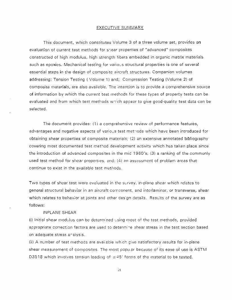
This document, which constitutes Volume 3 of a three volume set, provides an
evaluation of current test methods for shear properties of "advanced" composites
constructed of high modulus, high strength fibers embedded in organic matrix materials
such as epoxies. Mechanical testing for various structural properties is one of several
essential steps in the design of composite aircraft structures. Companion volumes
addressing: Tension Testing ( Volume 1) and; Compression Testing (Volume 2 ) of
composite materials, are also available. The intention is t o provide a comprehensive source
of information by which the current test methods for these types of property tests can be
evaluated and from which test methods which appear to give good-quality test data can be
selected.
The document provides: (1 ) a comprehensive review of performance features,
advantages and negative aspects of various test methods which have been introduced for
obtaining shear properties of composite materials; (2) an extensive annotated bibliography
covering most documented test method development activity which has taken place since
the introduction of advanced composites in the mid 1960's; (3 ) a ranking of the commonly
used test method for shear properties, and: (4) an assessment of problem areas that
continue to exist in the available test methods.
T w o types of shear test were evaluated in the survey, in-plane shear which relates t o
general structural behavior in an aircraft component, and interlaminar, or transverse, shear
which relates to behavior at joints and other design details. Results of the survey are as
follows:
INPLANE SHEAR
(i) Initial shear modulus can be determined using most of the test methods, provided
appropriate correction factors are used to determine shear stress in the test section based
on adequate stress analysis.
(ii) A number of test methods are available which give satisfactory results for in-plane
shear measurement of composites. The most popular because of i ts ease of use is ASTM
D35 18 which involves tension loading of r 45' forms of the material t o be tested.
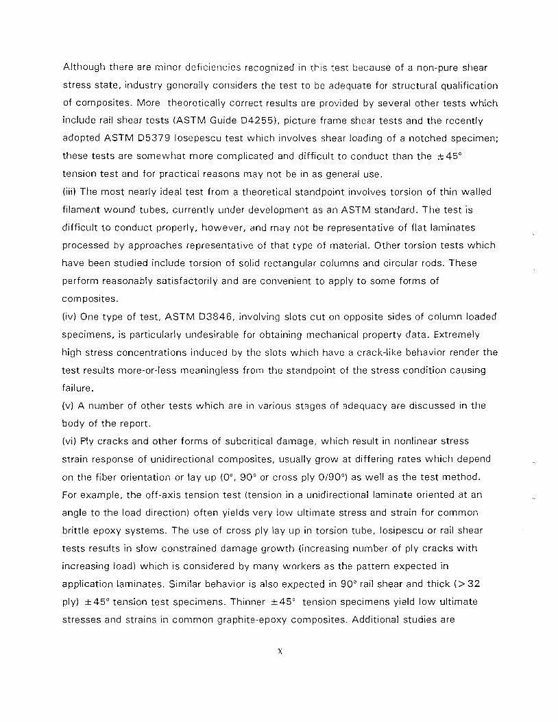
Although there are minor deficiencies recognized in t h ~ s test because of a non-pure shear
stress state, industry generally considers the test t o be adequate for structural qualification
of composites. More theoretically correct results are provided by several other tests which
include rail shear tests (ASTM Guide D42551, picture frame shear tests and the recently
adopted ASTM D5379 losepescu test which involves shear loading of a notched specimen;
these tests are somewhat more complicated and diff icult t o conduct than the +45 "
tension test and for practical reasons may not be in as general use.
(iii) The most nearly ideal test f rom a theoretical standpoint involves torsion o f thin walled
filament wound tubes, currently under development as an ASTM standard. The test is
diff icult t o conduct properly, however, and may not be representative of f lat laminates
processed by approaches representative of that type of material. Other torsion tests which
have been studied include torsion of solid rectangular columns and circular rods. These
perform reasonably satisfactori ly and are convenient t o apply t o some forms of
composites.
(iv) One type of test, A S T M D3846, involving slots cu t on opposite sides of column loaded
specimens, is particularly undesirable for obtaining mechanical property data. Extremely
high stress concentrations induced by the slots which have a crack-like behavior render the
test results more-or-less meaningless from the standpoint of the stress condit ion causing
failure.
(v) A number of other tests wh ich are in various stages of adequacy are discussed in the
body of the report.
(vi) Ply cracks and other forms of subcritical damage, which result in nonlinear stress
strain response of unidirectional composites, usually grow at differing rates which depend
on the fiber orientation or lay up (0°, 90" or cross ply 0190") as wel l as the test method.
For example, the off-axis tension test (tension in a unidirectional laminate oriented at an
angle t o the load direction) of ten yields very l ow ult imate stress and strain for common
brittle epoxy systems. The use of cross ply lay up in torsion tube, losipescu or rail shear
tests results in slow constrained damage g rowth (increasing number of ply cracks w i t h
increasing load) wh ich is considered by many workers as the pattern expected in
application laminates. Similar behavior is also expected in 90" rail shear and thick ( > 32
ply) k 4 5 " tension test specimens. Thinner k 4 5 " tension specimens yield l o w ult imate
stresses and strains in common graphite-epoxy composites. Additional studies are
suggested to address these issues.
(vii) Simple modifications t o some of the methods may yield better specimen performance.
For example, redesigning the grip regions in solid torsion specimens appears worthwhile.
On the other hand, significant modifications may be required in some other methods such
as picture frame or crossbeam.
INTERLAMINAR SHEAR
(i) losipescu tests w i th specimens prepared by bonding several layers of a material appear
t o be the only available method at this time for determining interlaminar stress strain
response. Obviously specimen preparation needs some effort and the quality of the bond
may affect the results in some cases.
(ii) short beam shear is one of the simplest test to conduct and it is often used, but test
data are usually not accepted as material shear properties, since failure can be influenced
by flexural and contact stresses. Further studies are suggested for three and four-point
loaded short beam as well as lap shear tests used for measuring shear strengths.
(iii) the slotted or notched shear test is possibly most economical, and for this reason i t is
often used for quality control purposes, but the results are influenced by the severity of
stress concentration at the notches. Because of the economy and wide usage, additional
studies are suggested for possible improvements of the test and careful comparison of test
data w i th those from other tests.
In summary, i t can be noted that a few standards are either available or under develop-
ment for some in plane shear test methods. Further work is suggested for improving the
k 4 5 O tension test for in plane shear and three- or four-point loaded short beam shear test
(or some other reliable method) for interlaminar shear. In the meantime, it is hoped that the
discussions and suggestions contained in this report will be useful in deciding on test
methods, specimens, procedures and interpretation of data.

OVERVIEW
GENERAL REMARKS
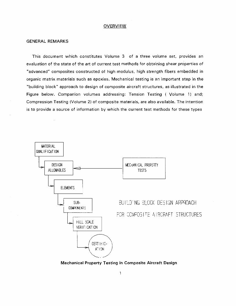
This document which constitutes Volume 3 of a three volume set, provides an
evaluation of the state of the art of current test methods for obtaining shear properties of
"advanced" composites constructed of high modulus, high strength fibers embedded in
organic matrix materials such as epoxies. Mechanical testing is an important step in the
"building block" approach t o design of composite aircraft structures, as illustrated in the
Figure below. Companion volumes addressing: Tension Testing ( Volume 1 ) and;
Compression Testing (Volume 2) of composite materials, are also available. The intention
is t o provide a source of information by which the current test methods for these types
QUALIFICATION
DES 1 GN MCMN I CAL PROPERTY ALLOWABLES
#--I
TESTS
7 ELEMENTS I
FULL SCALE VERIFICATION
BU I L D l NG BLOCK DES l GN APPROACH
FOR COMPOS l TE A l RCRAFT STRUCTURES
CERTIFIC- AT l ON
Mechanical Property Testing in Composite Aircraft Design
of property tests can be evaluated and from which test methods which appear to give
good-quality test data can be selected.
Mechanical property testing of advanced composites has been under development ever
since the introduction of such materials nearly a generation ago. The first major
conference on test methods for advanced composites, for example, took place in 1969
and culminated in ASTM Special Technical Publication STP 4 6 0 which summarized results
from a number of DoD programs that were ongoing at that time. The methods which were
reported on that occasion formed the basis for a number of test methods which are still
in use.
The methodology for obtaining mechanical properties of such materials contains a
number of inadequacies and is in need of continuing development. The purpose of this
discussion is t o review the issues which are significant drivers in efforts toward improved
testing methodology, in order t o provide a framework for evaluating the state of the art.
OBSERVATIONS ON MECHANICAL PROPERTY TESTING OF COMPOSITES
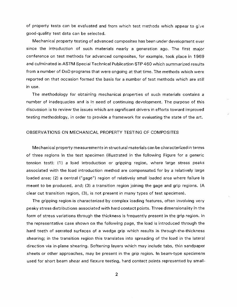
Mechanical property measurements in structural materials can be characterized in terms
of three regions in the test specimen (illustrated in the following Figure for a generic
tension test): (1) a load introduction or gripping region, where large stress peaks
associated w i th the load introduction method are compensated for by a relatively large
loaded area; (2) a central ("gage") region of relatively small loaded area where failure is
meant t o be produced, and; (3) a transition region joining the gage and grip regions. (A
clear cu t transition region, (3), is not present in many types of test specimen).
The gripping region is characterized by complex loading features, often involving very
peaky stress distributions associated w i th hard contact points. Three dimensionality in the
form of stress variations through the thickness is frequently present in the grip region. In
the representative case shown on the following page, the load is introduced through the
hard teeth of serrated surfaces of a wedge grip which results in through-the-thickness
shearing; in the transition region this translates into spreading of the load in the lateral
direction via in-plane shearing. Softening layers which may include tabs, thin sandpaper
sheets or other approaches, may be present in the grip region. In beam-type specimens
used for short beam shear and flexure testing, hard contact points represented by small-
1. LOAD l NTRODUCT i ON (GR I P) REG I ON
2. GAGE REGION
3 . TRANSITION REGION
Elements of Generic Test Specimen
radius rods of a relatively rigid material such as steel may be present tha t give rise t o
severe stress peaks in the load introduction region wh ich are unrelated t o the desired
stress state.
The ideal mechanical property tes t specimen would provide a large ef fect ive loaded area
in the grip region t o compensate for stress peaks caused by the gripping arrangement,
whi le al lowing the stresses in the gage region t o approach a uniform condit ion of h igh
stress wh i ch ensures tha t failure takes place in that region. Furthermore, suff icient volume
o f tes t material should be involved in the gage region t o provide an adequate sampling of
the variability wh ich is characteristic of the material being tested. For various reasons,
such an ideal form of behavior is hardly ever achieved in practical tes t specimens for
composite materials.
Specific problems wh i ch hamper successful mechanical property measurements in
organic matr ix composites wi l l be summarized at th is point.
Measurement of mechanical properties in organic-matrix composites is di f f icul t because
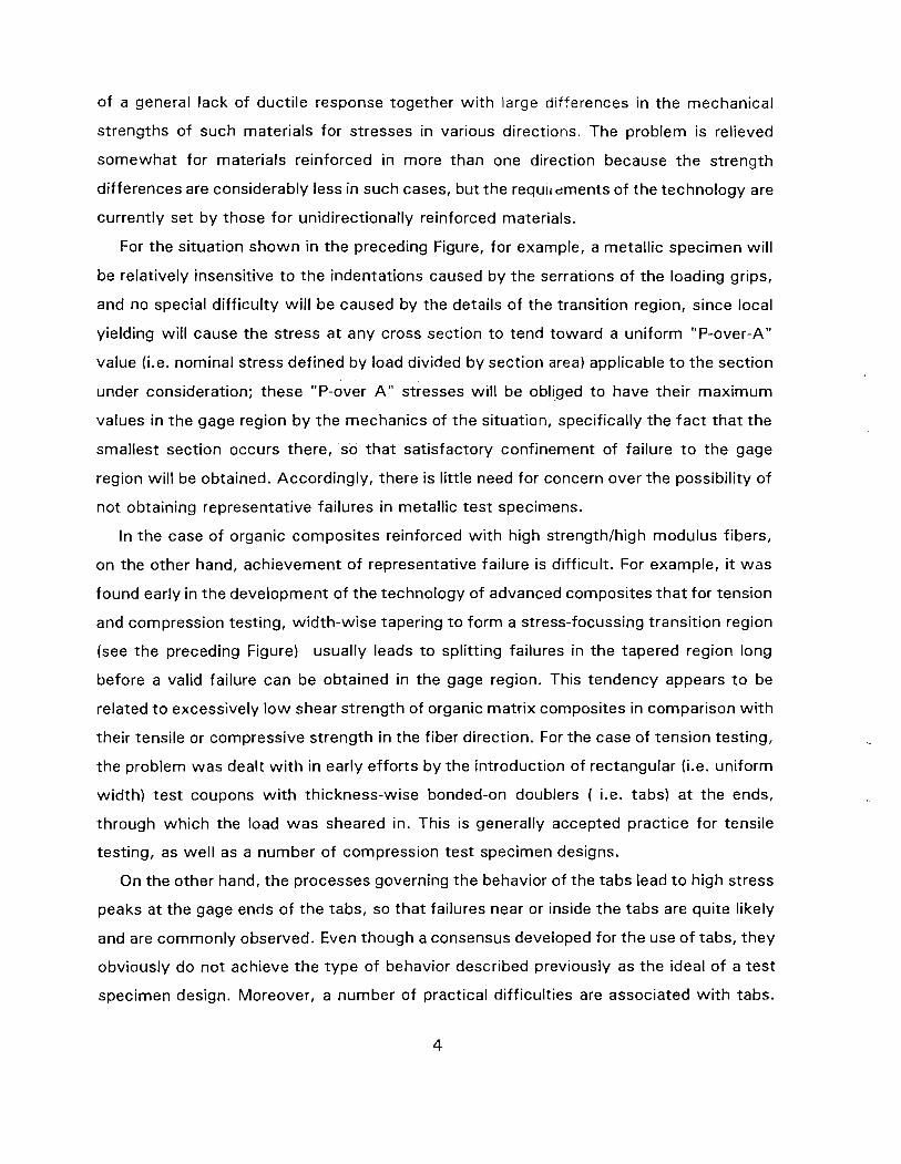
of a general lack of ductile response together w i th large d~fferences in the mechanical
strengths of such materials for stresses in various directions. The problem is relieved
somewhat for materials reinforced in more than one direction because the strength
differences are considerably less in such cases, but the requl~dments of the technology are
currently set by those for unidirectionally reinforced materials.
For the situation shown in the preceding Figure, for example, a metallic specimen will
be relatively insensitive t o the indentations caused by the serrations of the loading grips,
and no special difficulty will be caused by the details of the transition region, since local
yielding wil l cause the stress at any cross section t o tend toward a uniform "P-over-A"
value (i.e. nominal stress defined by load divided by section area) applicable t o the section
under consideration; these "P-over A " stresses wil l be obliged t o have their maximum
values in the gage region b y the mechanics of the situation, specifically the fact that the
smallest section occurs there, so that satisfactory confinement of failure t o the gage
region wil l be obtained. Accordingly, there is little need for concern over the possibility of
not obtaining representative failures in metallic test specimens.
In the case of organic composites reinforced w i th high strengthlhigh modulus fibers,
on the other hand, achievement of representative failure is difficult. For example, it was
found early in the development of the technology of advanced composites that for tension
and compression testing, width-wise tapering t o form a stress-focussing transition region
(see the preceding Figure) usually leads t o splitting failures in the tapered region long
before a valid failure can be obtained in the gage region. This tendency appears t o be
related t o excessively l ow shear strength of organic matrix composites in comparison w i th
their tensile or compressive strength in the fiber direction. For the case of tension testing,
the problem was dealt w i th in early efforts by the introduction of rectangular (i.e. uniform
width) test coupons w i th thickness-wise bonded-on doublers ( i.e. tabs) at the ends,
through which the load was sheared in. This is generally accepted practice for tensile
testing, as well as a number of compression test specimen designs.
On the other hand, the processes governing the behavior of the tabs lead t o high stress
peaks at the gage ends of the tabs, so that failures near or inside the tabs are quite likely
and are commonly observed. Even though a consensus developed for the use of tabs, they
obviously do not achieve the type of behavior described previously as the ideal of a test
specimen design. Moreover, a number of practical difficulties are associated w i th tabs.
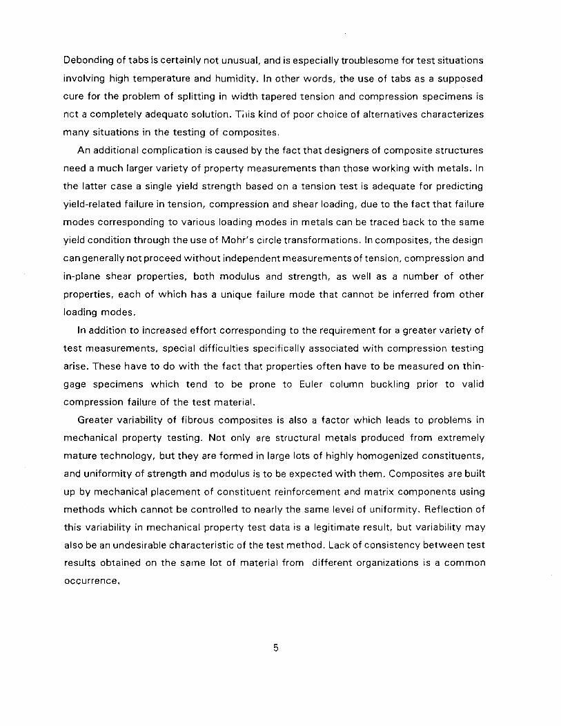
Debonding of tabs is certainly not unusual, and is especially troublesome for test situations
involving high temperature and humidity. In other words, the use of tabs as a supposed
cure for the problem of splitting in w id th tapered tension and compression specimens is
nc t a completely adequate solution. Ti l is kind of poor choice of alternatives characterizes
many situations in the testing of composites.
A n additional complication is caused by the fact that designers of composite structures
need a much larger variety o f property measurements than those working w i t h metals. In
the latter case a single yield strength based on a tension test is adequate for predicting
yield-related failure in tension, compression and shear loading, due t o the fac t tha t failure
modes corresponding t o various loading modes in metals can be traced back t o the same
yield condit ion through the use of Mohr's circle transformations. In composites, the design
can generally not proceed w i thou t independent measurements of tension, compression and
in-plane shear properties, both modulus and strength, as well as a number o f other
properties, each of which has a unique failure mode that cannot be inferred f rom other
loading modes.
In addition t o increased effort corresponding t o the requirement for a greater variety of
tes t measurements, special diff icult ies specifically associated w i t h compression test ing
arise. These have t o do w i t h the fac t that properties of ten have t o be measured on thin-
gage specimens wh ich tend t o be prone t o Euler column buckling prior t o valid
compression failure of t he test material.
Greater variability of f ibrous composites is also a factor which leads t o problems in
mechanical property testing. No t only are structural metals produced f rom extremely
mature technology, bu t they are formed in large lots of highly homogenized constituents,
and uniformity of strength and modulus is t o be expected w i t h them. Composites are buil t
up by mechanical placement of constituent reinforcement and matrix components using
methods wh ich cannot be controlled t o nearly the same level of uniformity. Reflection of
this variability in mechanical property test data is a legitimate result, but variability may
also be an undesirable characteristic of the test method. Lack of consistency between tes t
results obtained on the same lot of material f rom different organizations is a common
occurrence.
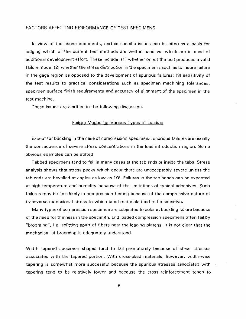
FACTORS AFFECTING PERFORMANCE OF TEST SPECIMENS
In v iew o f the above comments, certain specific issues can be ci ted as a basis for
judging wh ich of the current test methods are wel l in hand vs. which are in need o f
additional development effort. These include: ( 1 whether or not the test produces a valid
failure mode; (2) whether the stress distribution in the specimen is such as t o insure failure
in the gage region as opposed t o the development of spurious failures; (3) sensitivity o f
the tes t results t o practical considerations such as specimen machining tolerances,
specimen surface finish requirements and accuracy of alignment of the specimen in the
test machine.
These issues are clarified in t he fol lowing discussion.
Failure Modes for Various Tvpes of Loading
Except for buckling in the case of compression specimens, spurious failures are usually
the consequence of severe stress concentrations in the load introduction region. Some
obvious examples can be stated.
Tabbed specimens tend t o fail in many cases at the tab ends or inside the tabs. Stress
analysis shows tha t stress peaks which occur there are unacceptably severe unless the
tab ends are bevelled at angles as l o w as 10". Failures in the tab bonds can be expected
at high temperature and humidity because of the limitations of typical adhesives. Such
failures may be less likely in compression testing because of the compressive nature of
transverse extensional stress t o wh ich bond materials tend t o be sensitive.
Many types o f compression specimen are subjected t o column buckling failure because
of the need for thinness in the specimen. End loaded compression specimens of ten fail b y
"brooming", i.e. splitting apart of fibers near the loading platens. It is no t clear tha t the
mechanism of brooming is adequately understood.
Wid th tapered specimen shapes tend t o fail prematurely because of shear stresses
associated w i t h the tapered portion. Wi th cross-plied materials, however, width-wise
tapering is somewhat more successful because the spurious stresses associated w i t h
tapering tend t o be relatively lower and because the cross reinforcement tends t o
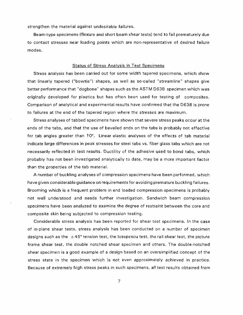
strengthen the material against undesirable failures.
Beam-type specimens (flexure and short beam shear tests) tend t o fai l prematurely due
t o contact stresses near loading points wh ich are non-representative o f desired failure
modes.
Status o f Stress Analysis in Test Specimens
Stress analysis has been carried out for some w id th tapered specimens, wh i ch show
tha t linearly tapered ( "bowt ie" ) shapes, as wel l as so-called "streamline" shapes give
better performance tha t "dogbone" shapes such as the A S T M D 6 3 8 specimen wh i ch was
originally developed for plastics bu t has of ten been used for testing of composites.
Comparison of analytical and experimental results have confirmed tha t the D 6 3 8 is prone
t o failures a t the end o f the tapered region where the stresses are maximum.
Stress analyses of tabbed specimens have shown tha t severe stress peaks occur at the
ends o f the tabs, and tha t the use of bevelled ends on the tabs is probably no t ef fect ive
for t ab angles greater than 10". Linear elastic analyses of the ef fects of t a b material
indicate large differences in peak stresses for steel tabs vs. fiber glass tabs wh i ch are not
necessarily ref lected in tes t results. Ducti l i ty of the adhesive used t o bond tabs, wh i ch
probably has no t been investigated analytically t o date, may be a more important fac tor
than the properties of t he tab material.
A number of buckl ing analyses of compression specimens have been performed, wh i ch
have given considerable guidance on requirements for avoiding premature buckling failures.
Brooming wh i ch is a frequent problem in end loaded compression specimens is probably
no t wel l understood and needs further investigation. Sandwich beam compression
specimens have been analyzed t o examine the degree of restraint between the core and
composi te skin being subjected t o compression testing.
Considerable stress analysis has been reported for shear tes t specimens. In the case
o f in-plane shear tests, stress analysis has been conducted on a number o f specimen
designs such as the k45" tension test, the losepescu test, the rail shear test, the picture
f rame shear test, the double notched shear specimen and others. The double-notched
shear specimen is a good example of a design based on an oversimplified concept of the
stress state in the specimen wh ich is no t even approximately achieved in practice.
Because of extremely high stress peaks in such specimens, all tes t results obtained f rom
them must be considered suspect. Stress analyses have also been performed on beam-
type specimens such as the short beam shear test for transverse shear properties t o
determine the ef fect of stress peaks around the load points.
Specimen Machininq and Aliqnment Effects
Machining tolerances for test specimens may be somewhat arbitrary. A rational basis
for sett ing tolerances may be developed from parametric studies of the ef fects o f
specimen machining errors, i.e. computer modelling of the influence o f non-planarity and
non-paralellism of specimen surfaces on the stress state in the specimen. Such studies
have been presented in the literature t o some extent, especially in the case of compression
testing where the concern for sensitivity of test results t o specimen imperfections is
generally prevalent. Specimen alignment is a crucial feature of many test methods, again,
especially in the case of compression testing. Some testing jigs have provided special
features for insuring precise specimen alignment. As in the case of machining tolerances,
requirements for alignment are of ten specified arbitrarily, and there is a need for combined
experimental and analytical studies t o establish these requirements more rationally in
several types of test.
FORMAT OF THE DOCUMENT
The preceding discussion il lustrates the type o f information that this report is intended
t o provide. Each o f the 3 volumes a provides comprehensive review of mos t o f the tes t
methods wh ich have been used for obtaining structural properties o f composite materials
over the years. These include mos t o f the standard methods which have been adopted by
ASTM, SACMA (Suppliers o f Advanced Composite Materials Association) as wel l as other
organizations, in addition t o a number o f methods which have become generally popular
in the industry bu t have no t been adopted as standards.
The format of each volume includes the following:
1. EXECUTIVE SUMMARY (constitutes a brief summary of the state o f testing
methodology for the type o f test ing addressed in the volume under consideration)
2. INTRODUCTION
3. SUMMARY AND RECOMMENDATIONS (includes a relative ranking of test methods
in each category, and recommendations for ef fort needed t o correct deficiencies)
4. DETAILED DISCUSSION ( a detailed discussion of each test method under
consideration, including: failure characteristics of the specimen; discussion of the status
of stress analysis for the specimen considered and conclusions t o be d rawn about the
ef fect o f stresses on test results and; practical considerations such as sensitivity t o
machining tolerances, specimen alignment requirements, etc)
In addition, an appendix is included w i t h each volume which contains an annotated
bibliography covering all of the available literature back t o the mid 60's wh ich it was
practical t o review wi th in the scope of this effort.
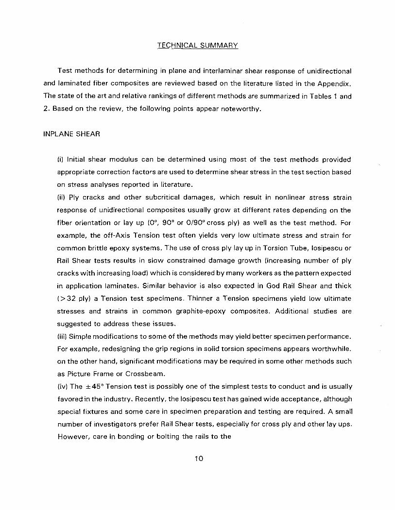
TECHNICAL SUMMARY
Test methods for determining in plane and interlaminar shear response of unidirectional
and laminated fiber composites are reviewed based on the literature listed in the Appendix.
The state of the art and relative rankings of different methods are summarized in Tables 1 and
2. Based on the review, the fol lowing points appear noteworthy.
INPLANE SHEAR
(i) Initial shear modulus can be determined using most of the test methods provided
appropriate correction factors are used t o determine shear stress in the test section based
on stress analyses reported in literature.
(ii) Ply cracks and other subcritical damages, which result in nonlinear stress strain
response of unidirectional composites usually grow at different rates depending on the
fiber orientation or lay up (0°, 90" or 0190" cross ply) as well as the test method. For
example, the off-Axis Tension test often yields very low ultimate stress and strain for
common brittle epoxy systems. The use of cross ply lay up in Torsion Tube, losipescu or
Rail Shear tests results in slow constrained damage growth (increasing number of ply
cracks w i th increasing load) which is considered b y many workers as the pattern expected
in application laminates. Similar behavior is also expected in God Rail Shear and thick
(> 32 ply) a Tension test specimens. Thinner a Tension specimens yield low ultimate
stresses and strains in common graphite-epoxy composites. Additional studies are
suggested t o address these issues.
(iii) Simple modifications t o some of the methods may yield better specimen performance.
For example, redesigning the grip regions in solid torsion specimens appears worthwhile.
on the other hand, significant modifications may be required in some other methods such
as Picture Frame or Crossbeam.
(iv) The * 45" Tension test is possibly one of the simplest tests t o conduct and is usually
favored in the industry. Recently, the losipescu test has gained wide acceptance, although
special fixtures and some care in specimen preparation and testing are required. A small
number of investigators prefer Rail Shear tests, especially for cross ply and other lay ups.
However, care in bonding or bolting the rails t o the
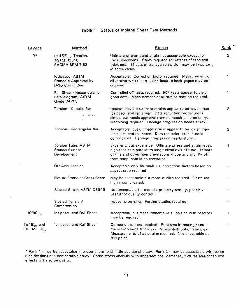
Table 1. Status of lnplane Shear Test Methods
Method
0 O ( * 4 5 O)ns, Tension, ASTM D35 1 8 SACMA SRM 7-88
losipescu, ASTM Standard Approved by D-30 Committee
Rail Shear - Rectangular or Parallelogram, ASTM Guide D4255
Torsion - Circular Bar
Torsion - Rectangular Bar
Torsion Tube, ASTM Standard under Development
Off-Axis Tension
Picture Frame or Cross Beam
Slotted Shear, ASTM D3846
Slotted Tension1 Compression
(0/90),,, losipescu and Rail Shear
(+-45),,, and losipescu and Rail Shear (OI* 45/90),,
Status Rank
Ultimate strength and strain not acceptable except for 2 thick specimens. Study required far effects of tabs and thickness. Effects of transverse tension may be important in some cases.
Acceptable. Correction factor required. Measurement of all strains wi th rosettes and back t o back gages may be required.
Controlled O0 tests required. 90 ° tests appear t o yield good data. Measurement of all strains may be required.
Acceptable, but ultimate strains appear t o be lower than losipescu and rail shear. Data reduction procedure is simple but needs approval f rom composites community. Machining required. Damage progression needs study.
Acceptable, but ultimate strains appear t o be lower than losipescu and rail shear. Data reduction procedure is complicated. Damage progression needs study.
Excellent, but expensive. Ultimate stress and strain levels high for fibers parallel to longitudinal axis of tube. Effects of this and other fiber orientations (hoop and slightly o f f f rom hoop) should be compared.
Acceptable only for modulus, correction factors based on aspect ratio required.
May be acceptable but more studies required. Tests are highly complicated.
Not acceptable for material property testing, possibly useful for quality control.
Appear promising. Further studies required.
Acceptable, but measurements of all strains wi th rosettes may be required.
Correction factors required. Problems in testing speci- mens wi th large thickness. Stress distribution complex. Measurements of all strains required. Not acceptable at this point.
Rank 1 - may be acceptable in present form wi th little additional study. Rank 2 - may be acceptable wi th some modifications and comparative study. Some stress analysis w i th imperfections, damages, fixtures and/or tab end effects will also be useful.
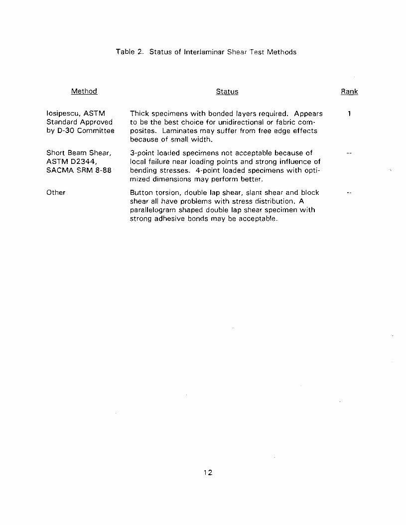
Method
losipescu, ASTM Standard Approved by D-30 Committee
Short Beam Shear, ASTM D2344, SACMA SRM 8-88
Other
Table 2. Status of Interlaminar Shear Test Methods
Status Rank
Thick specimens with bonded layers required. Appears 1 t o be the best choice for unidirectional or fabric com- posites. Laminates may suffer from free edge effects because of small width.
3-point loaded specimens not acceptable because of -- local failure near loading points and strong influence of bending stresses. 4-point loaded specimens wi th opti- mized dimensions may perform better.
Button torsion, double lap shear, slant shear and block --
shear all have problems wi th stress distribution. A parallelogram shaped double lap shear specimen wi th strong adhesive bonds may be acceptable.
specimens is needed for such tests. The Torsion Tube is the only test suitable for fi iament
wound cylinders, but for obvious reasons it is not favored for obtaining lamina or laminate
properties. Torsion tests on solid bars are simple, but data reduction procedures are
complicated in the nonlinear range because of nonuniform stress distribution and for this
reason they have not gained acceptance.
INTERLAMINAR SHEAR
losipescu tests w i t h specimens prepared by bonding several layers of a material
appear t o be the only available method at this t ime for determining interlaminar stress
strain response. Obviously specimen preparation needs some effort and the quality
of the bond may affect the results in some cases.
Short Beam Shear is one of the simplest test t o conduct and it is of ten used, but test
data are usually no t accepted as material shear properties, since failure can be
influenced by flexural and contact stresses. Further studies are suggested for three-
and four-point loaded Short Beam as well as Lap Shear tests used for measuring shear
strengths.
Slotted or Notched Shear test is possibly most economical, and for this reason it is
of ten used for quality control purposes, but the results are influenced by the severity
of stress concentration at the notches. Because of the economy and wide usage,
additional studies are suggested for possible improvements of the test and careful
comparison of test data w i t h those from other tests.
In summary, it can be noted that a f ew standards are either available or under develop-
ment for some inplane shear test methods. Further work is suggested for improving the
+ 4 5 O Tension test for inplane shear and three- or four-point loaded Short Beam Shear test
(or some other reliable method) for interlaminar shear. In the meantime, i t is hoped that the
discussions and suggestions contained in this report wil l be useful in deciding on test
methods, specimens, procedures and interpretation of data.
1. INTRODUCTION
The anisotropic nature of fiber composites introduces considerable complexity in shear
testing, and a thorough understanding of the behavior of test specimens is essential before
material property data generated from such tests can be used wi th confidence. The major
problem associated w i th the specimens is the difficulty in attaining uniform stress states
within the test section. Other problems are created due t o (i) inhomogeneity, (ii) various
coupling effects like shear extension coupling in laminates, (iii) interaction of various failure
modes and subcritical damage growth, and (iv) nonlinear shear stress strain response.
This volume describes the state of the art of inplane and interlaminar shear test methods
obtained from a literature search. The Appendix contains an annotated bibliography of the
works reported in literature. Many of the bibliographical entries are also directly referenced
in the discussions presented in the report. These are marked wi th an asterisk in the list of
references, so that the interested reader can refer t o the bibliography for more information.
Description of different methods, discussions, and recommendation are based solely on review
of these works. No additional research was conducted for preparation of this report. An
Executive Summary is given in the preceding section. The following section gives a detailed
summary of the state of the art and identifies areas where work appears needed. For each
method, the following points are addressed in the Summary.
1 . Problems associated wi th load introduction and free edges.
2. Uniformity of stress field.
3. Sensitivity t o imperfections.
4. Acceptability of failure modes.
5. Simplicity and adequacy of data reduction procedure.
6. Specimen preparation and fixture requirements.
7. Consistency of results and other informations.
Detailed discussions of the methods listed below are given in the sections which follow.
These discussions are appropriate for all fiber composite systems except where some
characteristic differences for a specific material are noted.
Torsion Tube
Torsion of a Circular Bar
Torsion of a Rectangular Bar
( * 45) Tension
losipescu
Arcan
Rail Shear
Off-axis Tension
Picture Frame
Crossbeam or Cruciform Specimen
Slotted Shear
Short Beam Shear
All the methods listed above may be used for inplane shear tests for unidirectional materials.
Some of them can be used for other laminate configurations. The last t w o are commonly
employed for interlaminar strength measurements. losipescu and Lap Shear tests may also
be used for this purpose.
A short discussion on some methods which are not very common is given in the last
section.
For each of the test methods mentioned above, the following issues are addressed.
GENERAL DESCRIPTION OF THE TEST METHOD - Description of the method and
procedure, which are commonly used, including drawings of specimens and fixtures.
STRESS STATES AND FAILURE MODES - General nature of the stress state,
representative results from stress analyses (if reported), disturbances and stress peaks
at critical locations such as load introduction points (including effects of grips, tabs,
fixtures and tab variations and problems in hot iwet testing). Common failure or
damage modes and consistency of results are also discussed.
DATA REDUCTION - Data reduction procedure.
OTHER REQUIREMENTS AND MODIFICATIONS - Other considerations such as
specimen machining tolerance and alignment requirements, effects of minor
imperfections (specimen, fiber geometry, etc.) and suggested variations of the method
for improving specimen performance.
2. SUMMARY AND RECOMMENDATIONS
This section gives a summary of findings related to each of the important methods
(discussed in the fol lowing sections) fol lowed by some recommendations identifying areas of
further work.
2.1 TORSION TUBE
1. Problems due t o load introduction can be significantly reduced by bonding the tubes
t o internal and external grips. Stress analyses show that stresses near such grips are
not as large as in the case of bonded tabs, and end ef fects decay very quickly. A gage
length t o diameter ratio of the order 2 may be adequate.
2. The stress state is practically uniform (for small thickness t o diameter ratio) over a
large volume of material. The test is ideal in this respect.
3. Effects of imperfections have not been reported. However, care is needed t o detect
buckling possibilities. Thickness may have t o be increased t o avoid this problem.
4. Hoop wound cylinders fail a t a comparatively low strain level, which cannot be
accepted as representative lamina behavior in a laminate where plycracks do not cause
sudden catastrophic failure. Tubes w i t h fibers parallel t o the axis or a crossply
( 0 ° / 9 0 0 ) layup wi l l be a better choice, but they are diff icult t o make.
5. Data reduction procedure is simple.
6. Test cannot be used for materials in the form of f lat plates.
7. Data reported in literature are usually consistent in the linear range. For obvious
reasons, ult imate strains and strengths depend on the fiber orientation, i.e., axial or
hoop wound, the latter one being susceptible t o catastrophic failure due t o crack
propagation in the hoop direction. Modu l~ , strengths and ult imate strains obtained in
different laboratories participating in Joint Army-Navy-NASA-Air Force (JANNAF) [ I I
round robin (+89 .5O orientation of fibers to axial direction) appear t o be consistent.
2.2 TORSION OF SOLID CIRCULAR BAR
Grip regions are usually made square. Constrained crack g rowth starts f rom this
region. Length t o diameter ratio of 1 5 (or more) is required. End ef fects decay, but
ef fect of grip regions has no t been studied.
Stress state varies along the radius but is the same over a large length along the axis.
M a y not be sensitive t o minor imperfections.
Al though ult imate strains are usually higher than those from hoop wound cylinders, it
is possible tha t even higher ult imate strains can be obtained by redesigning t he grip
regions and minimizing the possibility of cracks starting f rom these regions.
A simple data analysis procedure is available for linear as wel l as nonlinear response.
Machining is required. Test is suitable for comparatively th ick plates but not for th in
ones.
No data are available t o reach any conclusion about consistency of results f rom
different sources.
2.3 TORSION OF SOLID RECTANGULAR BARS
End effects decay, but length t o w id th ratio of 2 0 (or more) may be needed t o reduce
ef fects of end constraints. Constrained cracks start f rom the gripped regions, but no
analysis of stresses in those regions is reported.
Stress state varies in the cross-section but is practically independent of axial location
over a large length along the specimen axis.
Probably not sensitive t o minor imperfections.
Constrained spli t t ing starts in the gripped region and extends toward the center.
Ult imate strains are comparable t o those from torsion of circular bars. A s in the latter
case, redesigning t he grip regions may yield higher ult imate strains.
Data analysis is simple for linear elastic cases, but is complicated in the inelastic
problem. Further wo rk is required t o simplify data analysis procedure in the inelastic
range.
Although machining is not required, moderately th ick specimens ( 2 4 plies) are needed.
7. No data are available t o reach a conclusion about consistency of results from different
sources.
2.4 (*45),, TENSION
1. End Effects are not important. Tabs are possibly not needed. I t is not clear whether
tabs have any effect on failure. Free edge effects do exist, but are possibly not critical
wi th dispersed layups. 314" - 1" width is adequate.
2. Stress state is uniform over a large area except near the free edges, but for obvious
reasons vary from layer t o layer. Transverse tensile stresses exist in each layer and
they increase w i th increasing ratio of transverse Young's modulus t o axial modulus.
I t is, therefore, surprising that GrIEp fails at shear strain levels lower than that for
GIIEp. Lower fracture toughness or poor fiberlmatrix interface quality in GrIEp may be
the reason.
3. May be sensitive t o minor variation in fiber orientations, but the effect has not been
quantified.
4. Mechanism of damage growth appears to be representative of lamina behavior within
a laminate, i.e., generation of increasing number of ply cracks. However, damage
initiates early and failure occurs at low strain levels when plies are lumped. Even wi th
dispersed layups, low failure strains are obtained wi th small number of layers, since
significant load redistribution from the thick layers (which crack early) t o other layers
which have less cracks (or crack later because of lower thickness) can not occur t o
prevent early failure. Specimens w i th 3 2 or more plies do not fail before hardening due
t o the occurrence of scissoring ( > 5 % shear strain level for GrIEp).
5. Data analysis procedure is simple, but may not be accurate for large crack densities.
6. Specimen preparation is not complicated and no special loading fixtures are required.
7 . Results from various sources are usually consistent in the linear range. In the nonlinear
range results may differ depending on the number of plies as discussed earlier.
Load introduction can cause problems in gage section unless the loading points are
placed away from this region. Use of 1 10° or 1 20° notch and larger specimens (3"
x 0.75) with O 0 fiber orientation is required for this reason. Edge effects near the
notch can cause delaminations in laminates with st45O layers on the surfaces. For
unidirectional (0° and 90°) or cross ply layups, edge effects do not play a major role.
Local crushing can occur near loading points for +45 layups. I t is not clear whether
tabs used to avoid such crushing cause any undue stiffening.
Stress state is uniform over a small region, but the response is found to be comparable
to torsion tube, solid bar torsion and rail shear tests. Combined stresses exist, but do
not appear to cause early failure in gage section. Round notches are necessary.
Appropriate correction factor is required for shear stress.
Imperfections can play a major role. Twisting is suspected to be the cause of early
failure of 90° specimens. Flat loading surfaces and proper shimmings are required to
avoid out of plane bending. Back-to-back gages should be employed to check for
irregularities in loading.
Local splitting parallel to fibers occur near the notches in O 0 specimens which causes
load drops long before final failure. Such splitting is the result of stress concentration
at the notch. Out of plane bending can contribute to early splitting. The splits,
however, get arrested as they approach the loading points. Cross ply specimens also
show some minor splits but without any load drops. Such specimens also show many
small cracks (constrained ply cracks parallel to fibers, which are created due to shear)
which is the damage mode expected in a laminate. Similar cracks are often not
noticeable in O 0 specimens, possibly because of large splits, but it is likely that
microcracks do occur to yield a nonlinear shear stress-strain response. I t appears that
damage modes in O 0 and (0/90) specimens are acceptable, but 90° specimens fail
early due to the easy fracture path available between the notches and this does not
appear t o be a valid mode of failure in a ply within a laminate.
The method seems adequate for O 0 and (0190) specimens. ( + 45) specimens may
fail under loading points. Testing of (+45) and quasi-isotropic layups is difficult
because of the high loads required for failure.
5. Data reduction is simple, but three-element rosettes may be desirable because of
combined stress state. Some back-to-back gages should also be employed to check
for out of plane bending and/or twisting effects.
6. Specimen preparation needs some effort and special fixtures are required.
7. The results from various sources appear to be consistent for O 0 and (0190) graph-
itelepoxy specimens i f appropriate care is taken to avoid loading irregularities and
proper correction for shear stress is used. I t is not clear whether the high ultimate
strains obtained are due to constraints imposed by the fixtures and/or non-uniformity
of the stress state in the specimen. Inconsistency in the results has, however, been
reported for metal matrix composites wi th large diameter fibers like boron. Such
inconsistencv may possibly be attributed to the small size of the gage section.
The test has also been used for interlaminar shear properties for unidirectional and
laminated or woven composites by making moderately thick specimens w i th bonded
layers. I t has been shown to be successful for unidirectional materials. For laminates,
the results can be influenced by free edge effects because of small widths of the
specimens.
2.6 ARCAN
1. No standard gripping procedure can be employed because of the shape of the
specimen. Use of intermediate grips has been suggested. Edge effects near the notch
may cause delaminations in some laminated specimens (as discussed in the section on
losipescu specimens). Bonding of aluminum loading fixture to a small specimen of the
shape of the notched test area may be difficult for laminates wi th high shear strengths.
2. Stress state in the test section may be acceptable [21 but i t is complex slightly away
from test section. No analysis is reported for small specimens bonded to aluminum
fixtures wi th tabs.
3. Effects of imperfections have not been studied.
4. Failure mode of unidirectional specimens wi th fibers parallel to critical section is in the
form of a straight cut (as in 90° losipescu specimen) and it is not acceptable. No
result is reported about failures in other layups.
5. Data reduction procedure is simple, but correction factors (based on analyses) may be
required for nonuniform shear stress distribution.
6. Specimen preparation is complicated.
7. Available data are limited t o reach any conclusion about consistency of results.
2.7 RAIL SHEAR
Load introduction is a problem in two- as well as three-rail shear tests. Use of bolted
rails and tensile loads may require retightening of bolts during loading. Bonded and
tapered rails loaded in compression improve the situation, but stress smgularities exist
near loaded corners. Compliant adhesives may weaken this singularity t o some extent.
However, stresses remain high near the corners and unidirectional specimens w i th
fibers parallel t o rails (0° orientation) develop cracks near these corners, which may
cause large scatter in test data and low strength. Artificially introduced cracks at
these locations or the use of a parallelogram shaped specimen have been suggested
t o avoid this problem. For obvious reasons, such local cracking is not critical in 90'
or (0/90) layups.
Stress state is fairly uniform over a large distance (width is usually % " between rails)
near the center of the specimen. However, axial as well as transverse stresses exist.
A correction factor slightly higher than 1.0 is required t o account for slight non-
uniformity in shear stress.
Misorientation of fibers may affect the results, but the effects have not been
quantified.
As discussed earlier, failure strains of O0 unidirectional specimens are usually lower
because of cracks generated near the loaded corners. 90° unidirectional (fibers
perpendicular to rails) and (0190) layups fail at comparatively high strains after a
considerable amount of constrained cracking, which appears to be an acceptable
failure mode. Local compressive failure can occur in very thin 9 0 ° unidirectional
specimens. Bond failure may occur in thick specimens and/or in layups which are
strong in shear (quasi-isotropic or +45 layup). Better adhesives and/or larger bond
length may be utilized t o solve this problem. The method is acceptable for 90° and
(0190) specimens w i th moderate thicknesses, such that compressive failure does not
occur near loaded corners. Although the method is attractive for quasi-isotropic and
( k 4 5 ) layups more tests are need for such layups.
Data reduction is simple, but three-element rosettes should be used because of the
presence of combined stresses.
Specimen preparation is not complicated, but bonding tapered rails t o the specimen is
a very diff icult process.
No conclusion can be made regarding the consistency of results f rom different
sources. Ult imate strains are usually high for 9 0 ° and (0190) layups as compared t o
torsion (tube or solid bars), but i t is not clear whether that is due t o constraints
imposed by rails.
2.8 OFF-AXIS TENSION
1. End effects are important and have been studied in detail. Rotating end grips are
required and correction factors (which depend on aspect ratio and off-axis angle) are
needed t o obtain correct shear modulus. This is the reason stiffer response has been
reported in many past studies before such correction factors were calculated.
Alternatively tab designs have been optimized or use of flexible tabs has been
attempted.
2. Stress state is uniform over a large portion, but transverse tensile stresses are high and
contribute significantly towards failure.
3. Slight differences in off-axis angle can cause changes in the response
4. Failure occurs under combined mode. Graphitelepoxy specimens have been observed
t o fail a t very l ow strain levels, which is not acceptable. Use of failure theory has been
suggested as a solution t o the problem, but i t does not appear t o be the right approach
for determining nonlinear shear response. Therefore, the test does no t appear suitable
i f response in the nonlinear region is required.
5 . Data reduction procedure is not very complex, but three-element rosettes are required.
6. The specimen is simple, but special rotating grips are required as described earlier.
7. Wi th appropriate correction for shear stress, the results are consistent for moduli. Low
ult imate strains have also been reported in most of the studies.
2.9 PICTURE FRAME
To avoid buckling possibilities, a sandwich w i t h a honeycomb core is o f ten employed.
High stresses exist near the corners, where loads are applied through a loading frame.
These areas are usually cu t out. Doublers are applied near the specimen edges which
are pinned at the corners.
Corner stresses remain high even w i t h the modifications. However, the stresses can
be reduced somewhat by placing the loading pins on the frames at the corners of the
original specimen. Shear stress distribution, however, shows significant non-
uniformity unless the doublers are very sti f f , which is diff icult t o achieve in practice.
Effects of imperfections have no t been studied, but buckling is t o be avoided if a
sandwich construction is no t used.
Not much detail is available about the failure mode. Some researchers believe ult imate
strength may be obtained accurately, because the shear stress is uniform in critical
areas (near the edges) where failure initiates. Some workers feel tha t modulus can not
be evaluated because of non-uniform shear stresses in the gage section.
Data reduction procedure is no t complicated but it is clear tha t a correction factor is
required t o obtain the correct shear stress.
The specimen and f ixtures are complicated. Biaxial loading is also required wh ich is
achieved through a complicated linkage system.
N o conclusion can be reached about consistency of results.
2.1 0 CROSS BEAM OR CRUCIFORM SPECIMEN
1. T o avoid buckling possibilities, the cross specimens subjected t o tensile and
compressive stresses in the t w o directions are of ten bonded t o a honeycomb core.
Load introduction does not pose any serious problem in the cross beam.
2. Past studies have dealt w i t h ( f 45 ) and (0190) layups, the f irst for yielding the shear
response of a (0190) laminate and the second one giving the result for a ( f 4 5 ) layup.
Shear stress distribution in the first case is highly non-uniform and a correction factor
is required for determining the shear stress at the center. Extensional stresses are high
near the corners in both cases. Stresses in the cruciform and the cross beam face
sheets are found t o be similar. Rounding the notches yields more acceptable stress
distribution. Shear stiffness of the core is found to have some effect on the stress
distribution in the cross beam.
Effects of imperfections (misorientation of fibers, etc.) have not been studied in detail.
(0/90),, cruciform may buckle and are sensitive t o alignment.
Failure usually initiates near the corners and for this reason may not be an acceptable
mode of failure.
Data reduction procedure is simple, but corrections are usually required as discussed
earlier.
The specimen is complicated and fixtures for biaxial loading are required.
Modulus results are consistent but strength and ultimate strain may not be reliable
except possibly in specimen wi th rounded corners.
2.1 1 SLOTTED SHEAR
1. Load introduction does not pose a problem.
2. Stress state is not acceptable - shear stress is high near the tips of the slots. Non-
uniformity of stress and small specimen size make strain measurement impossible.
3. Results are strongly affected by the depth of the slots and i t is often diff icult t o make
the slots of depth equal t o half the specimen depth. This is expected t o be a more
serious problem in specimens for determining interlaminar strength for which the test
is commonly used.
4. The test specimen appears t o be similar to mixed mode fracture toughness tests and,
therefore, the failure mechanisms is not as acceptable as that causing failure under a
more or less uniform stress state.
5. Curve f i t t ing procedures appear t o yield good strength data based on measurements
from specimens w i th different distances between slots, but i t can not be accepted as
a measure of strength. The test may be used for quality control purposes.
6. The specimen needs precision cutting of slots.
7. No data base exists t o judge the consistency of results from different sources.
2.12 SHORT BEAM SHEAR
Load introduction can cause local failure under the loading noses. Use of proper radius
of noses, soft loading pads, and four-point loading can reduce severe effects of such
local damages but only t o a limited extent.
In addition to stress concentrations under loading points, existence of bending stresses
complicates the stress state. Bending stresses can also be reduced by using the four-
point loaded specimen. Non-uniform shear stress distribution and small depths (the
test is commonly employed for interlaminar shear strength) make measurement of
strains impossible. Due t o nonuniform shear stress distribution along the midplane,
shear strength is often over estimated (by the assumption of parabolic variation) and
perhaps for this reason the test sometimes yield strengths comparable t o inplane shear
strengths.
Effects of specimen imperfections are not known, but probably not significant.
Failure often occurs in mixed mode and is also influenced by damage under the loading
noses.
Data reduction is simple, but the assumption of parabolic shear stress distribution may
not be always valid for strength calculation.
Specimen preparation is simple.
The test is simple and for this reason it is commonly used for quality control purposes.
The results wil l possibly yield consistent data if all specimen parameters and load
introduction methods (pads, nose radius, etc.) are kept the same. However, these
parameters are often varied.
2.13 OTHER TESTS
Plate Twist, Four Point Ring Twist and Split Ring tests are usually suitable for determining
the modulus and are useful in certain circumstances. I t does not appear that these tests can
be used for obtaining the shear response or the strength.
The Slotted Tension/Compression test is a specimen wi th slots at both ends subjected t o
biaxial load, i.e., tension parallel t o the slots and compression on the other t w o sides (in the
central region between the slots) and appears t o be promising. I t has been employed in one
study and practically no data are available regarding the failure mechanism or consistency of
results.
Button Torsion, Lap Shear, Slant Shear and Block Shear tests have also been used by
some investigators for determining interlaminar shear strength. Stress states in these
specimens are highly complex. Bond failures in Button Torsion and Double Lap Shear tests
have been found t o occur before specimen failure. Slant Shear specimens under compression
do not fail in this fashion, but the results are found t o depend on the compressive stress. A
suitable design modification t o the Lap Shear test (w i th parallelogram shaped specimens
bonded t o rails wi th strong adhesives) has been found to be successful in testing of carbon-
carbon composites. Data from such tests are too scarce t o reach any conclusion about the
failure mode and consistency of results.
2.14 RECOMMENDATIONS
I t should be noted that developments and modifications of the methods are still continuing.
A "snapshot" of the status of all the methods at this point in time and some relative rankings
are given in Tables 1 and 2 . Based on the summary given above and the detailed discussions
and results in the following sections, some areas of future work are identified below. These
studies would be useful for improving specimen performance.
1. Stress analyses near gripped regions in Torsion tests (tube and solid bar) wil l be useful.
Modification of gripped regions (wi th or without tabs) t o control splitting of solid bars
may be attempted. Damage growth in such specimens should also be studied.
Differences in the response of axially reinforced and hoop wound cylinders should be
quantified in a systematic manner.
2 . Effects of small areas of uniform shear in losipescu and constraints imposed by rails
in Rail Shear test should be studied via tests (changing dimensions) and/or stress
analyses (modeling constrained damage growth andlor inelastic effects). Stress
analyses of 90° Rail Shear specimens appear necessary for comparison w i th O0 results
and correlation w i th test data. Suggested new modifications of these t w o tests should
also be investigated. Tests are also needed to determine the adequacy of fixtures and
specimen sizes of + 4 5 O or quasi-isotropic layups which can be used in practice.
Instrumentation requirements in both of these specimens need to be identified.
3. Thickness (number of plies) effects in ( * 45 O),, Tension Test should be investigated
analytically (modeling damage growth) as well as experimentally for various materials
t o confirm the results reported in literature and decide on the thickness to be used in
practice.
4. The biaxially loaded Slotted Tension/Compression fixture may be studied further,
provided the loading arrangement is not too complicated and expensive.
5. More analyses and tests are required to examine the performance of Short Beam Shear
(3- and 4-point loaded) and losipescu specimens for determining the interlaminar
strength and response. These tests, along w i th a bonded Lap Shear test wi th a
parallelogram shaped section, as well as Slotted Shear specimens, should be
investigated in future studies, since there is a need for a reliable interlaminar shear
test.
6. Direct comparison of test results from selected methods for a fiber dominated and a
non-fiber dominated layup wil l be useful. Use of crossply testing (instead of
unidirectional) may be advantageous in some ways for determining inplane shear
response of unidirectional materials.
3. DETAILED DISCUSSIONS
3.1 TORSION TUBE
3.1.1 General Desc r i~ t i on of the Test Method
Tests on thin tubes of various dimensions have been suggested by many investigators for
determining the inplane shear response of unidirectional materials or laminates made of plies
w i t h different orientations. A specimen which has been found t o perform wel l for hoop
wound ( & 89.5) cylinders ( in the Joint Army-Navy-NASA-Air Force sponsored round robin
conducted as a part of MIL-HDBK-17 activities [1 I) is shown in Figure 1 . The specimen is
bonded w i t h a pott ing compound t o end fixtures and devices t o which torsional loading is
applied (Figure 2). The gage length t o diameter (LID) ratio is unity. Suggested bond lengths
a t the ends are 0.75" for specimens of thickness 0.08". Thickness t o diameter (TID) ratio is
0.02. Use of a t least t w o three-element strain gage rosettes (at -45O, 0 ° , 45' t o the
specimen axial direction) is recommended. Strain measurements are made a t various values
of the applied torque. I t may be noted that testing of th in tubes has also been suggested for
off-axis tension as wel l combined stress tests [3-51.
3.1.2 Stress States and Failure Modes
The stress state in a torsion tube is ideal for shear characterization except near the ends.
Some analyses of the particular specimen configuration described above have also been
reported. From the results in [ I , 3-51, it appears that t /D ratio should be less than 0.02 so
tha t the variation of stress though the thickness is small. Effects of external and internal
gripping (of the type shown in Figure 2) on stress distribution in tubes w i t h fibers at 30° t o
the axial direction ( f rom [51) are il lustrated in Figure 3. The results indicate that shear stress
disturbance (variation f rom gage section value) becomes small at a small distance from the
grips, bu t the axial stress disturbance in off-axis specimens (w i th shear extension coupling)
persists up t o a distance equal t o 20 t o 30 t imes the thickness. Therefore, the LID ratio of
1 suggested in [1 I may be adequate for hoop wound tubes, although LID > 2 is recommend-
ed in [41. Stress distributions in tubes subjected t o other types of loading are also reported
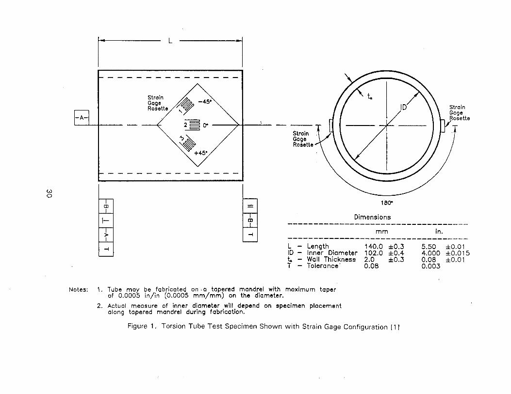
Strain 4'
Strain Gage Raaette
m m in. ----------------------------------- L - Length 140.0 h0.3 5.50 hO.01 ID - Inner Diameter 102.0 f 0.4 4.000 f 0.01 5 t - Wall Thickness 2.0 f 0.3 0.08 fO.01 T - Tolerance' 0.08 0.003
Notes: 1. Tube may be fabricated on - a tapered mandrel with maximum taper of 0.0005 in/in (0.0005 mm/mm) on the diameter.
2. Actual measure of inner diameter wlll depend on specimen placement along tapered mandrel during fabrication.
Figure 1. Torsion Tube Test Specimen Shown w i t h Strain Gage Configuration [ I ]
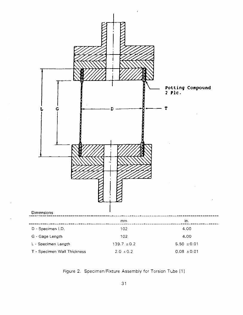
Dimensions
1 Potting 2 Plc. Compound
mm in. .............................................................................................. D - Specimen I.D. 102 4.00
G - Gage Length 102 4.00
L - Specimen Length 139.7 =0.2 5.50 k0.01
T - Specimen Wall Thickness 2.0 r 0 . 2 0.08 50.01
Figure 2 . SpecimenIFixture Assembly for Torsion Tube [ I I
3 1
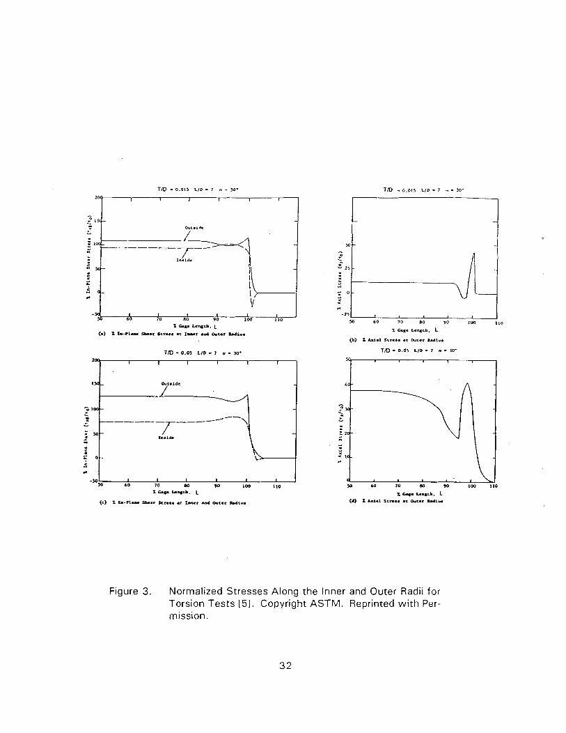
TID - 0.01, LID - 7 n - >o-
T m - 0.05 LID - I m - 30. m
Figure 3. Normalized Stresses Along the Inner and Outer Radii for Torsion Tests 151. Copyright ASTM. Reprinted w i t h Per- mission.
150-
- 0 loo- . - - -
= so- a2
5 2 0- C " .. -%
Outside
-
------ - --- -/-- 7 \
- Ins1&
I I I I I I 60 70 W M 1Q) 110
1 C a r I.-web. L
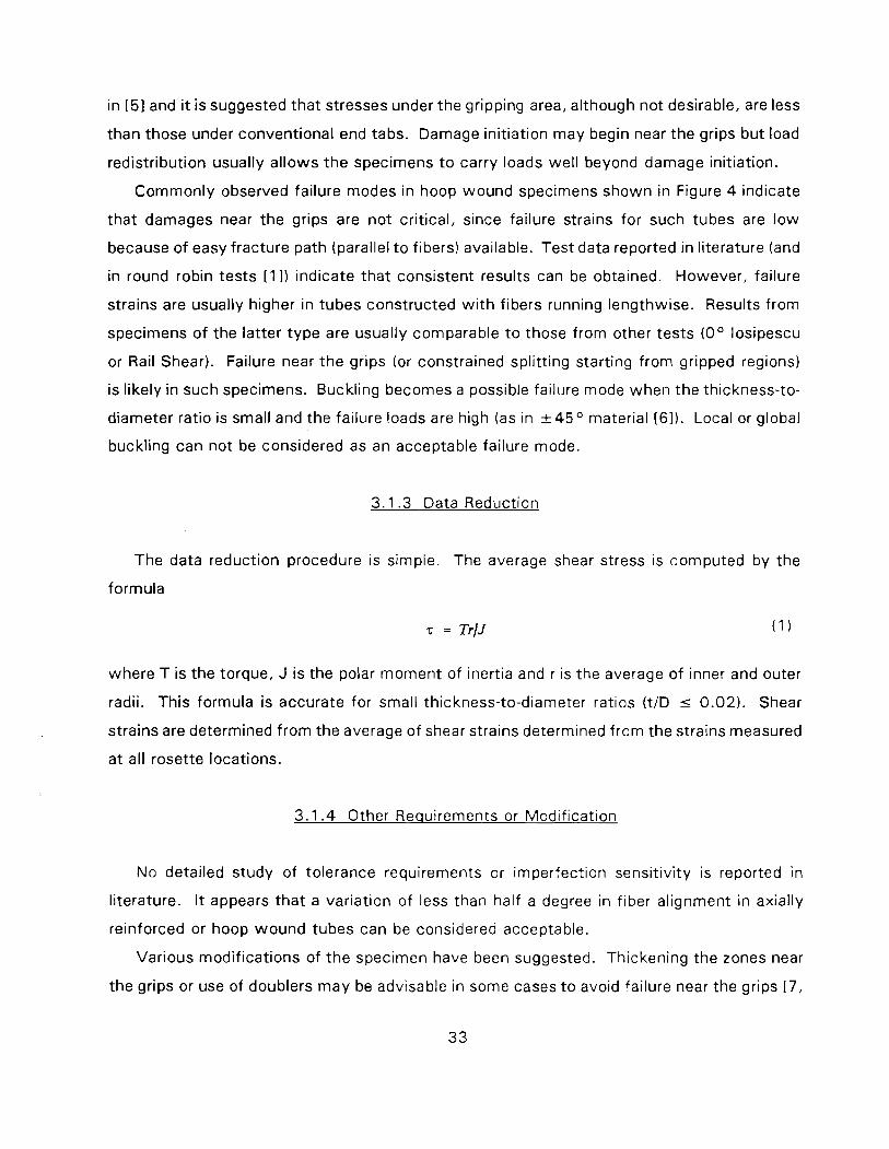
in [51 and it is suggested that stresses under the gripping area, although not desirable, are less
than those under conventional end tabs. Damage initiation may begin near the grips but load
redistribution usually allows the specimens t o carry loads well beyond damage initiation.
Commonly observed failure modes in hoop wound specimens shown in Figure 4 indicate
that damages near the grips are not critical, since failure strains for such tubes are low
because of easy fracture path (parallel t o fibers) available. Test data reported in literature (and
in round robin tests [ I ] ) indicate that consistent results can be obtained. However, failure
strains are usually higher in tubes constructed w i th fibers running lengthwise. Results from
specimens of the latter type are usually comparable to those from other tests (0° losipescu
or Rail Shear). Failure near the grips (or constrained splitting starting from gripped regions)
is likely in such specimens. Buckling becomes a possible failure mode when the thickness-to-
diameter ratio is small and the failure loads are high (as in &45O material [61). Local or global
buckling can not be considered as an acceptable failure mode.
3.1.3 Data Reduction
The data reduction procedure is simple. The average shear stress is computed by the
formula
where T is the torque, J is the polar moment of inertia and r is the average of inner and outer
radii. This formula is accurate for small thickness-to-diameter ratios (t/D I 0.02). Shear
strains are determined from the average of shear strains determined from the strains measured
at all rosette locations.
3.1.4 Other Requirements or Modification
No detailed study of tolerance requirements or imperfection sensitivity is reported in
literature. I t appears that a variation of less than half a degree in fiber alignment in axially
reinforced or hoop wound tubes can be considered acceptable.
Various modifications of the specimen have been suggested. Thickening the zones near
the grips or use of doublers may be advisable in some cases t o avoid failure near the grips [7,
81 . Special fabrication processes are, however, required for this purpose.
The torsion test is advantageous when the material is made by the filament winding
process. It can not be used t o test materials made in the form of f lat plates.
3.2 TORSION OF CIRCULAR BAR
3.2.1 Desc r i~ t i on of the Test Method
In contrast t o th in tubes, testing of solid bars is easier t o conduct and has been suggested
by many investigators [9-121 for unidirectional composites. The specimens used are shown
in Figure 5. For the purpose of strain measurements (rosettes are recommended; single 45
gages may also be used if no axial stresses are expected), bars of a minimum diameter of
0.25" ( to be machined from 48 ply thick material) are possibly required. 0.25" and 0.4"
diameter bars were used in 11 1 1 . The specimens were tested in INSTRON Model 1 125 testing
machining using three-jaw Jacobs chucks t o apply a torsional load. The gripped length at
each end w a s 1.75". No end tabs or other attachments are required. A minimum gage
length-to-diameter ratio (LID) of 16 is necessary. Larger diameter specimens used in [1 1 I
needed small f lats ground at the ends t o prevent slipping. A n alternative is t o machine the
circular bars form 0.25" square bars leaving the ends square [I 01 as shown in Figure 5. Tw is t
and strain measurements should be made near the center of the gage section for various
values of the applied torque.
3.2.2 Stress States and Failure Modes
A uniform state of shear strain does not exist even in the gage section, since strain
increases linearly f rom zero at the center t o a maximum value on the surface. In the inelastic
range the stress distribution is nonlinear. The non-uniform strain and stress distributions are,
however, no t a problem, since a simple data reduction procedure is available. The stress state
is very complicated near the grips and, in the ideal elastic problem, a stress singularity exists
a t the grip boundary. Effects of end disturbance are expected t o decay rapidly and test data
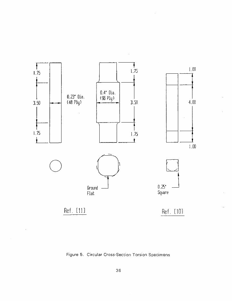
0.23' Dia. (48 P l y )
0.4' Dia. (96 Ply 1 P
9 Ground F l a t
Re f . [ \ I 1
Square
R e f . 1101
Figure 5. Circular Cross-Section Torsion Specimens
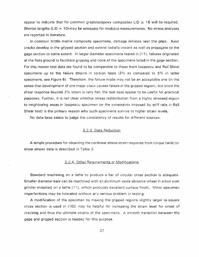
appear t o indicate that for common graphitelepoxy composites LID 2 16 wil l be required.
Shorter lengths (LID .= 10) may be adequate for modulus measurements. No stress analyses
are reported in literature.
In common brittle matrix composite specimens, damage initiates near the grips. Axial
cracks develop in the gripped section and extend radially inward as well as propagate t o the
gage section t o some extent. In larger diameter specimens tested in [1 1 I, failures originated
at the f lats ground t o facilitate gripping and none of the specimens failed in the gage section.
For this reason test data are found t o be comparable t o those f rom losipescu and Rail Shear
specimens up t o the failure strains in torsion tests ( 3 % as compared t o 5 % in latter
specimens, see Figure 6). Therefore, the failure mode may not be an acceptable one (in the
sense that development of one major crack causes failure in the gripped region), but since the
shear response beyond 3 % strain is very flat, the test data appear t o be useful for practical
purposes. Further, it is not clear whether stress redistribution from a highly stressed region
t o neighboring areas in losipescu specimen (or the constraints imposed by st i f f rails in Rail
Shear test) is the primary reason w h y such specimens survive t o higher strain levels.
No data base exists t o judge the consistency of results for different sources.
3 .2 .3 Data Reduction
A simple procedure for obtaining the nonlinear stress strain response from torque tw i s t (or
shear strain) data is described in Table 3 .
3.2.4 Other Reauirements or Modifications
Standard machining on a lathe t o produce a bar of circular cross section is adequate.
Smaller diameter bars can be machined w i t h an aluminum oxide abrasive wheel in a tool post
grinder mounted on a lathe [1 11, which produces excellent surface finish. Minor specimen
imperfections may be tolerated wi thout any serious problem in testing.
A modif ication of the specimen by making the gripped regions slightly larger (a square
cross section i s used in [ lo]) may be helpful for increasing the strain level for onset of
cracking and thus the ult imate strains of the specimens. A smooth transition between the
gage and gripped section is needed for this purpose.
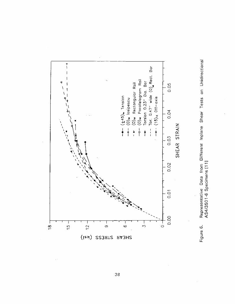
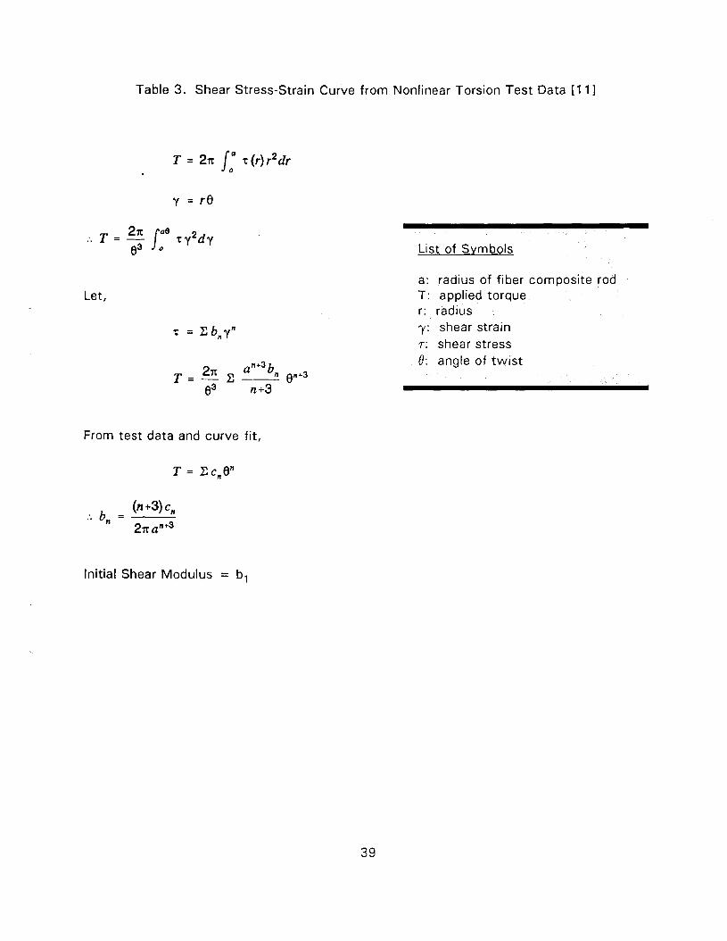
Table 3. Shear Stress-Strain Curve from Nonlinear Torsion Test Data [ I 1 I
Let,
From test data and curve fit,
List of Svmbols
a: radius of fiber composite rod T: applied torque r: radius y: shear strain 7: shear stress 8 : angle of tw is t
Initial Shear Modulus = b,
3 .3 TORSION OF RECTANGULAR BAR
3.3.1 General Desc r i~ t i on of the Test Method
T o minimize machining requirements, the use of rectangular bars of unidirectional materials
has been suggested by some investigators. The measurement of shear modulus from such
tests is reported in [ I 31. Determination of the stress-strain response in the inelastic range is
discussed i n [ I l l . The specimen is of constant cross-section (2b x 2a). For ease i n
instrumentation for strain measurements, a minimum wid th (2b) of 0.5" is possibly required.
0 .5 and 0.75" widths have been used i n [ I 11. T o reduce the sti f fening ef fect due t o axial
stresses (stiffening a t high shear strain level) w id th t o thickness ratio should be of the order
o f 2 or less. Therefore, for 0 .5 " wide, specimens should be about 4 8 ply ( .25") thick. The
ratio of gage length t o w id th (LI2b) should be of the order of 20. Tw is ts and strains (three-
element rosettes at - 45 O , 0 O , 4 5 O t o specimen axis) should be measured near the center of
the gage length. Torsional loads may be applied in a manner similar t o those for circular
specimens discussed earlier. However, one of the chucks should no t be constrained axially
t o minimize axial stresses, wh ich are unavoidable in these specimens.
3.3.2 Stress States and Failure Modes
Uniform states of shear strain or stress do no t exist even in the gage section. I n fact, they
are more complicated than those i n a circular bar, although they are constant over a large
region away from the grips. A n appropriate data reduction procedure can, however, be
employed considering the variation of stresses over the cross section (as discussed later).
Stress disturbances exist near the grips w i t h stresses peaking at the grip boundary (not
quantified by any stress analysis) as in circular bars wh ich imply that suff icient length must
be al lowed for such disturbances t o decay. In addition t o these ef fects there are t w o other
factors wh ich influence the performance of rectangular bars as discussed next.
(i) Warping Constraints - Approximate calculations for th in cross-sections show that
when the ends are no t free t o warp, axial stresses exist a t the ends and the shear
stresses as wel l as the rotation between the t w o ends are reduced. Approximate
estimates of these reductions are given below for the elastic case.
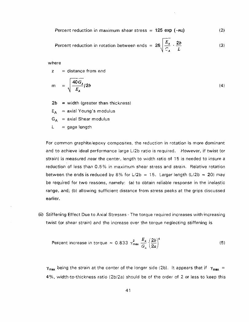
Percent reduction in maximum shear stress = 125 exp (-mz)
Percent reduction in rotation between ends = 26 . - 4": where
z = distance f rom end
2 b = wid th (greater than thickness)
EA = axial Young's modulus
GA = axial Shear modulus
L = gage length
For common graphitelepoxy composites, the reduction in rotation is more dominant
and t o achieve ideal performance large Ll2b ratio is required. However, i f t w i s t (or
strain) is measured near the center, length t o width ratio of 15 is needed t o insure a
reduction of less than 0 . 5 % in maximum shear stress and strain. Relative rotation
between the ends is reduced by 8 % for L l2b = 15 . Larger length (L l2b = 20) may
be required for t w o reasons, namely: (a) t o obtain reliable response in the inelastic
range, and; (b) al lowing suff icient distance f rom stress peaks at the grips discussed
earlier.
(ii) Stif fening Effect Due t o Axial Stresses - The torque required increases w i t h increasing
t w i s t (or shear strain) and the increase over the torque neglecting sti f fening is
Percent increase in torque .= 0 . 8 3 3 y,,
Ymax being the strain a t the center of the longer side (2b). It appears that i f y,, =
4%, width-to-thickness ratio (2b l2a) should be of the order of 2 or less t o keep this
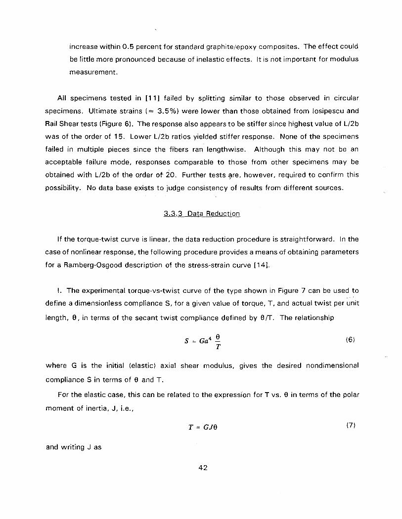
increase within 0.5 percent for standard graphitelepoxy composites. The effect could
be little more pronounced because of inelastic effects. I t is not important for modulus
measurement.
All specimens tested in [ 1 11 failed by splitting similar t o those observed in circular
specimens. Ultimate strains ( = 3.5%) were lower than those obtained from losipescu and
Rail Shear tests (Figure 6). The response also appears t o be stiffer since highest value of L12b
was of the order of 15. Lower L12b ratios yielded stiffer response. None of the specimens
failed in multiple pieces since the fibers ran lengthwise. Although this may not be an
acceptable failure mode, responses comparable t o those from other specimens may be
obtained wi th L12b of the order of 20. Further tests are, however, required t o confirm this
possibility. No data base exists t o judge consistency of results from different sources.
3.3.3 Data Reduction
If the torque-twist curve is linear, the data reduction procedure is straightforward. In the
case of nonlinear response, the following procedure provides a means of obtaining parameters
for a Ramberg-Osgood description of the stress-strain curve [141.
I. The experimental torque-vs-twist curve of the type shown in Figure 7 can be used t o . -
define a dimensionless compliance S, for a given value of torque, T, and actual twist per unit
length, 0 , in terms of the secant twist compliance defined by 0/T. The relationship
where G is the initial (elastic) axial shear modulus, gives the desired nondimensional
compliance S in terms of 0 and T
For the elastic case, this can be related to the expression for T vs. 0 in terms of the polar
moment of inertia, J, i.e.,
and writing J as
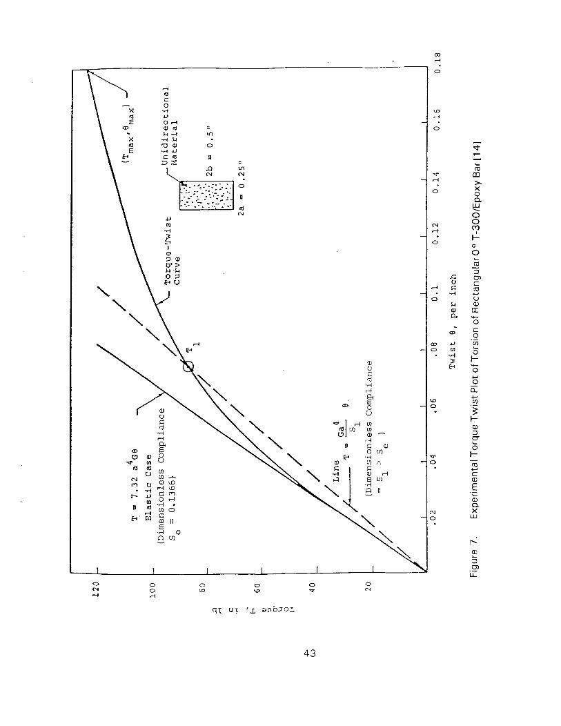
5 z U
., . -_. - )+, * -- - - II
- - - ...-. -. . - . . .. -- ITJ N
c,
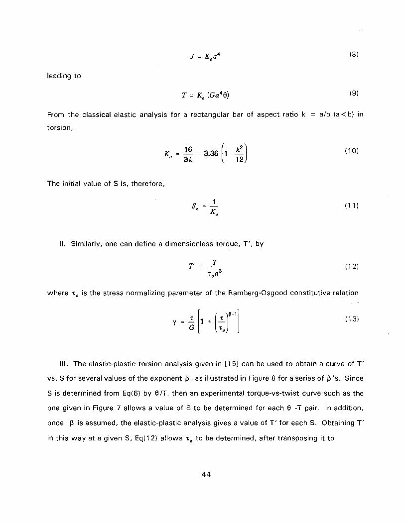
leading t o
From the classical elastic analysis for a rectangular bar of aspect ratio k = a/b (a < b) in
torsion,
The initial value of S is, therefore,
II. Similarly, one can define a dimensionless torque, T', by
toaY
where ro is the stress normalizing parameter of the Ramberg-Osgood constitutive relatior
Ill. The elastic-plastic torsion analysis given in [ I 51 can be used t o obtain a curve of T '
vs. S for several values of the exponent p , as illustrated in Figure 8 for a series of P 's. Since
S is determined from Eq(6) by 0/T, then an experimental torque-vs-twist curve such as the
one given in Figure 7 allows a value of S to be determined for each 0 -T pair. In addition,
once p is assumed, the elastic-plastic analysis gives a value of T ' for each S. Obtaining T'
in this way at a given S, Eq(12) allows ro t o be determined, after transposing it t o
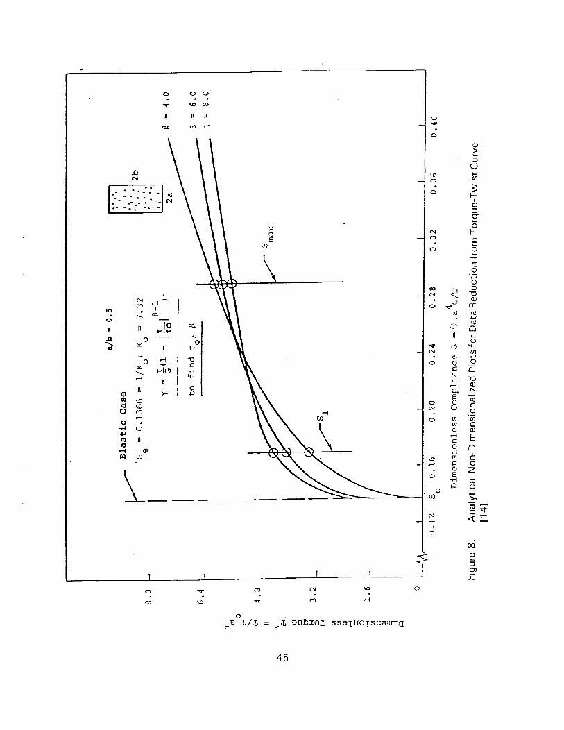
0 11 PIP
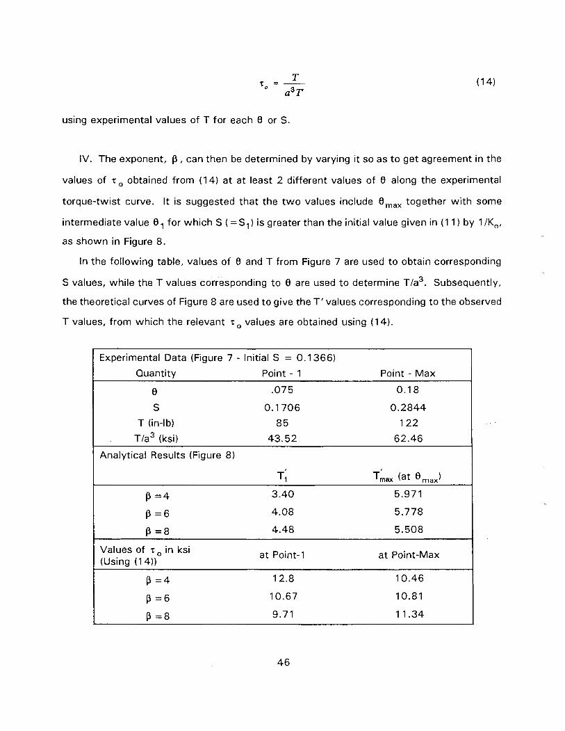
using experimental values of T for each 0 or S.
IV. The exponent, p , can then be determined by varying it so as t o get agreement in the
values of r o obtained from (14) a t at least 2 different values of 0 along the experimental
torque-twist curve. I t is suggested that the t w o values include Omax together w i th some
intermediate value 0, for which S (=S,) is greater than the initial value given in (1 1 ) by 1 /KO,
as shown in Figure 8.
In the following table, values of 0 and T from Figure 7 are used t o obtain corresponding
S values, while the T values corresponding t o 0 are used t o determine ~ / a ~ . Subsequently,
the theoretical curves of Figure 8 are used t o give the T ' values corresponding t o the observed
T values, from which the relevant r values are obtained using (1 4) .
Experimental Data (Figure 7 - Initial S = 0.1 366)
Quantitv Point - 1 Point - Max
0
S
T (in-lb)
~ / a ~ (ksi)
Analytical Results (Figure 8 )
Values of r in ksi at Point-1 at Point-Max (Using (1 4))

A p value of about 6 gives the closest match in t o for the t w o T-0 pairs, and would
represent an appropriate selection of the Ramberg-Osgood exponent. Numerical interpolation
of the above table could be used to get a more precise value. The procedure may be
automated, i f desired.
3.3.4 Other Reauirements and Modifications
No machining other than cutting a bar of finite width is required. I t appears that minor
specimen imperfection may not have much influence on specimen performance. Modification
or thickening of the end zones (keeping the width the same) may be attempted to examine
whether higher failure strains can be obtained from these specimens. Use of tabs may also
be tried for this purpose.
3.4 (_+45O) TENSION
3.4.1 General Description of the Test Method
Uniaxial tension test of a (+45O),, laminate is a simple but accurate method for
determining the shear modulus of unidirectional composites and is widely used in industry.
An ASTM Standard D3518 [I 61 exists, which suggests the use of specimens as per ASTM
D3039 for tension test (Figure 9). Commonly employed widths vary from '/z" t o 1 " . Use of
tabs is usually not necessary for common organic matrix composites. Length between tabs
for gripped regions is usually of the order of 6 to 8". Axial and transverse strains are
measured using strain gages or extensometers.
3.4.2 Stress States and Failure Modes
It has been shown that the shear stresses (in layer coordinates) in each of the layers are
equal t o half of the average laminate stress [17-191. However, in addition to the shear stress,
axial (in fiber direction) and transverse tensile stresses exist in each of the layers. The layer
stresses for unit applied tensile stress are presented in Figure 10 as a function of longitudinal
and transverse Young's moduli of the layers [ 1 1, 141. The stress distribution is, however,
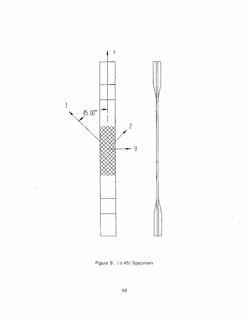
Figure 9. ( k 45) Specimen
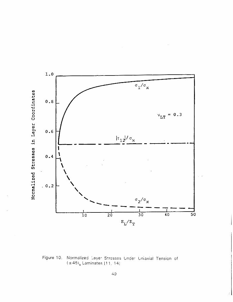
Figure 10. Normal ized Layer Stresses Under Uniaxial Tension of ( & 45), Laminates [ 1 1 , 141
49
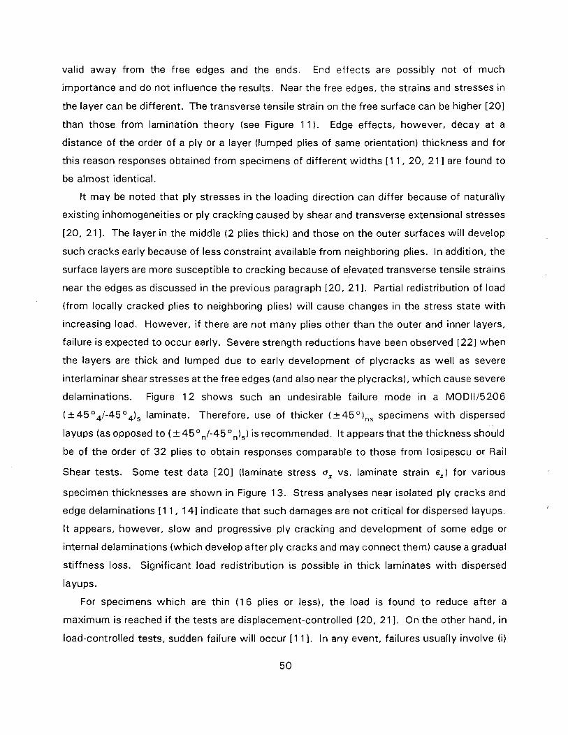
valid away from the free edges and the ends. End effects are possibly not of much
importance and do not influence the results. Near the free edges, the strains and stresses in
the layer can be different. The transverse tensile strain on the free surface can be higher 1201
than those from lamination theory (see Figure 11 ). Edge effects, however, decay at a
distance of the order of a ply or a layer (lumped plies of same orientation) thickness and for
this reason responses obtained from specimens of different widths [ I 1, 20, 21 I are found to
be almost identical.
I t may be noted that ply stresses in the loading direction can differ because of naturally
existing inhomogeneities or ply cracking caused by shear and transverse extensional stresses
120, 21 I. The layer in the middle ( 2 plies thick) and those on the outer surfaces wil l develop
such cracks early because of less constraint available from neighboring plies. In addition, the
surface layers are more susceptible t o cracking because of elevated transverse tensile strains
near the edges as discussed in the previous paragraph 120, 21 I. Partial redistribution of load
(from locally cracked plies t o neighboring plies) will cause changes in the stress state w i th
increasing load. However, i f there are not many plies other than the outer and inner layers,
failure is expected to occur early. Severe strength reductions have been observed [221 when
the layers are thick and lumped due to early development of plycracks as well as severe
interlaminar shear stresses at the free edges (and also near the plycracks), which cause severe
delaminations. Figure 1 2 shows such an undesirable failure mode in a MOD1115206
( k 4 5 04/-45 04), laminate. Therefore, use of thicker ( k 45 O),, specimens w i th dispersed
layups (as opposed t o (+45O,/-45 On),) is recommended. I t appears that the thickness should
be of the order of 3 2 plies t o obtain responses comparable t o those from losipescu or Rail
Shear tests. Some test data 1201 (laminate stress o, vs. laminate strain e,) for various
specimen thicknesses are shown in Figure 13. Stress analyses near isolated ply cracks and
edge delaminations [ I 1, 141 indicate that such damages are not critical for dispersed layups.
I t appears, however, slow and progressive ply cracking and development of some edge or
internal delaminations (which develop after ply cracks and may connect them) cause a gradual
stiffness loss. Significant load redistribution is possible in thick laminates w i th dispersed
layups.
For specimens which are thin (1 6 plies or less), the load is found t o reduce after a
maximum is reached i f the tests are displacement-controlled [20, 21 I. On the other hand, in
load-controlled tests, sudden failure will occur 11 1 I . In any event, failures usually involve (i)
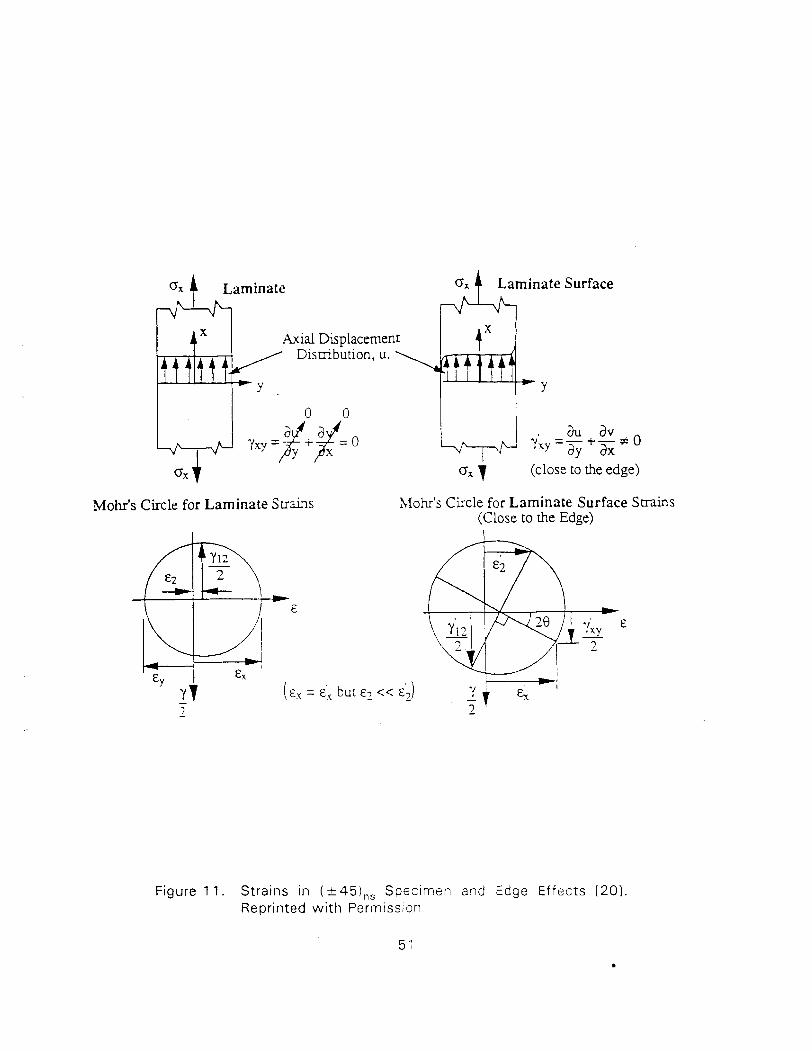
Mohr's Circle for Laminate Suains Mohr's Circle for Laminate Surface Strains (Close to rhe Edge)
inate Surface
Figure 1 1. Stra ins i n ( + 45),, Spec imen and Edge Ef fec ts [201 Repr inted w i t h Permission
5 1
X
t t t t t t - 6
Yxy - X y x y = - + - 3 0 I ay ax
Ox 7 (close to the edge)
X Axial Dsplacement
Dismbution, u.
v )-Y
0 0 au av
Figure 12. A Typical Undesirable Failure Mode due to Lumped Layup (454/-454),. Courtesy: D.W. Oplinger, FAA Technical Center
cracks along fibers in outer plies w i th some delaminated regions and (ii) fiber breaks in
subsurface plies [ I 1 I. Sometimes the role of outer and subsurface plies are reversed and if
the thickness is of the order of 16 plies, failure may not occur in all plies. However, in very
thick laminates (> 2 4 plies), separation of specimens may not occur and stiffening is
observed [20, 21 I after 5 t o 6% strain level (for graphitelepoxy) because of fiber scissoring
effect (Figure 13). However, the response beyond the 5 % strain level is not of practical
interest. The mechanism of progressive damage (ply crack) growth appears t o be
representative of what may be expected in a laminate or structural component. Test data
from different sources are usually consistent in the linear range. Responses, however, are
different depending on the number of plies in the specimen as discussed above.
3.4.3 Data Reduction
The data reduction procedure is simple and well documented in ASTM D35 18. I t is based
on the fact that under ideal conditions (no damage) the shear stress is given by [I 61
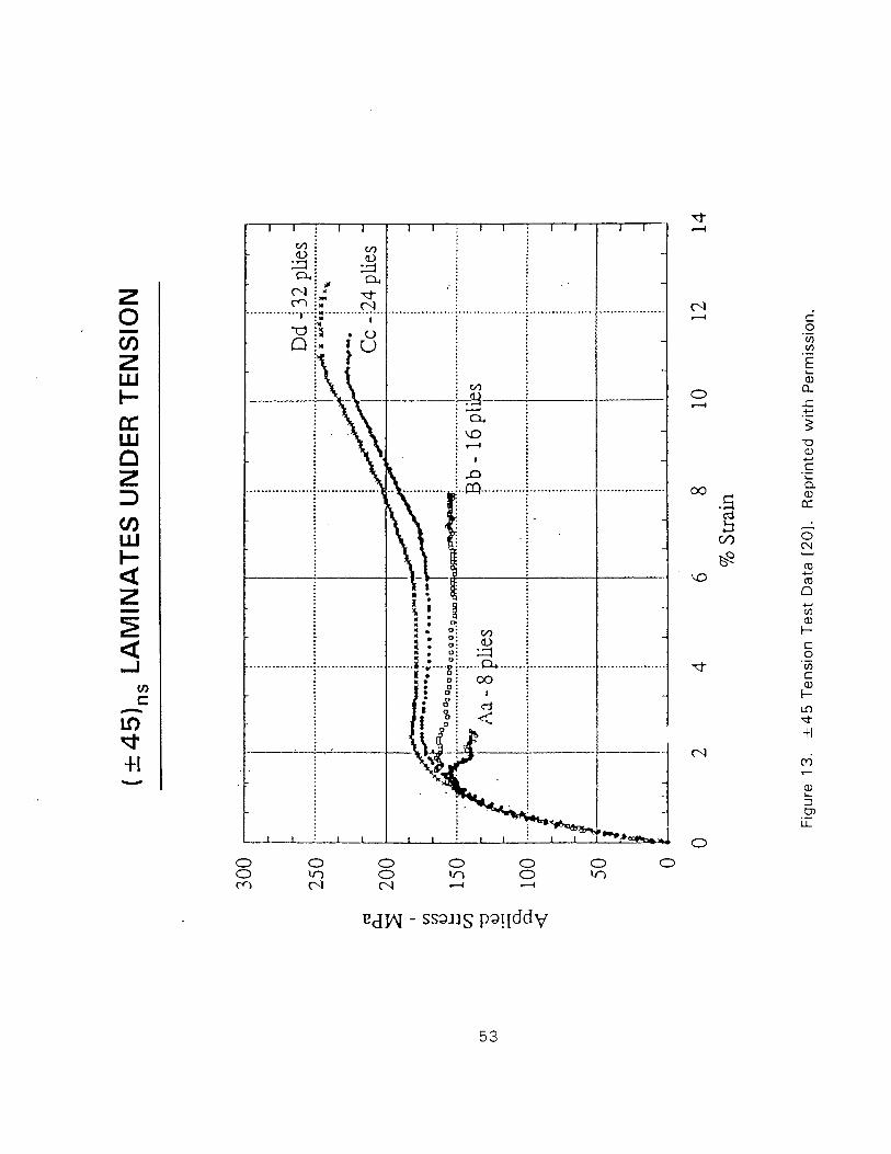
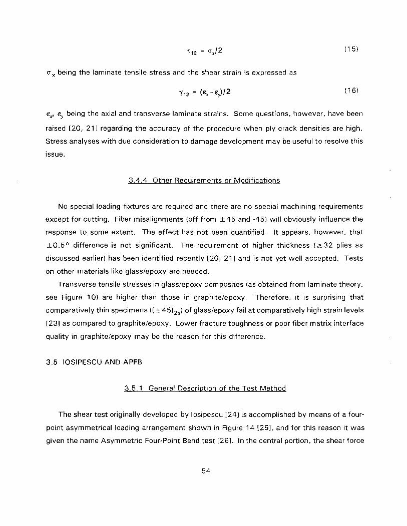
a, being the laminate tensile stress and the shear strain is expressed as
ex, e, being the axial and transverse laminate strains. Some questions, however, have been
raised 120, 21 I regarding the accuracy of the procedure when ply crack densities are high.
Stress analyses w i th due consideration to damage development may be useful t o resolve this
issue.
3.4.4 Other Requirements or Modifications
No special loading fixtures are required and there are no special machining requirements
except for cutting. Fiber misalignments (off from + 4 5 and -45) wil l obviously influence the
response t o some extent. The effect has not been quantified. I t appears, however, that
i ~ 0 . 5 ~ difference is not significant. The requirement of higher thickness ( 2 3 2 plies as
discussed earlier) has been identified recently 120, 211 and is not yet well accepted. Tests
on other materials like glasslepoxy are needed.
Transverse tensile stresses in glasslepoxy composites (as obtained from laminate theory,
see Figure 10) are higher than those in graphitelepoxy. Therefore, it is surprising that
comparatively thin specimens ( ( +45)2,) of glasslepoxy fail a t comparatively high strain levels
[231 as compared to graphitelepoxy. Lower fracture toughness or poor fiber matrix interface
quality in graphitelepoxy may be the reason for this difference.
3.5 IOSlPESCU AND APFB
3.5.1 General Descr i~ t ion of the Test Method
The shear test originally developed by losipescu 1241 is accomplished by means of a four-
point asymmetrical loading arrangement shown in Figure 1 4 1251, and for this reason it was
given the name Asymmetric Four-Point Bend test 1261. In the central portion, the shear force
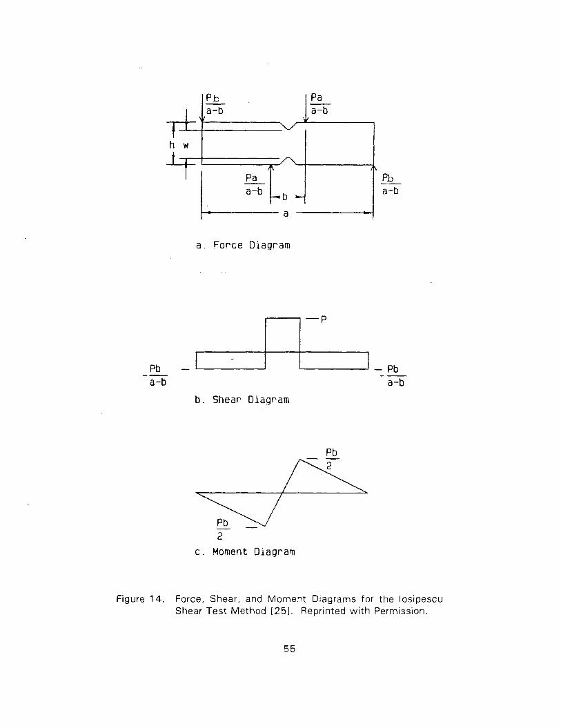
a . F o r c e Diagram
1 ' \ I
h w
Pb - -- - Pb -- a-b a-b
b . Shear Diagram
P b - a-b
2
c . Moment Diagram
t i A
a
Figure 14. Force, Shear, and Moment Diagrams for the losipescu Shear Test Method [251. Reprinted w i t h Permission.
I\ pb a-b
Pa - a-b
i/ 7
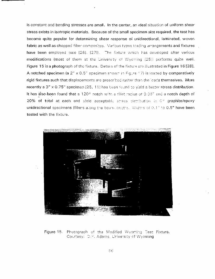
is c0nstan.t and bending stresses are small. In the center, an ideal situation of uniform shear
stress exists in isotropic materials. Because of the small specimen size required, the test has
become quite popular for determining shear response of unidirectional, laminated, woven
fabric as well as chopped fiber composites. Various types loading arrangements and fixtures
have been employed isee [261, [271). The fixture ivhich has developed after various
modifications (most of them at the University o f L'Jyornirig L2511 performs quite well.
Figure 15 is a photograph of the fixture. Details of ;he fixture are illustrated in Figure 16 [281.
A notched specimen (a 2" x 0.5" specimen shown in F ~ g u r e ! 71 is loaded by comparatively
rigid fixtures such that displacements are prescribed rather than rhe ioads themseives. More
recently a 3" x 0.75" specimen [ 25 , 111 has been t ound to yield a better stress distribution.
I t hasalso-been found that a 1 20° notch w i ~ h a :il iet radius of 0.35" a n d a notch depth of
20% of t&al at each end yield acceptable;. s:r.ass 3istri! jutioll [I.: 0" graphitelepoxy
unidirectional specimens (fibers along the beam length!. .$S1ldrr::; :;cf 5.1 " ro 0.5" have been
tested w i th the fixture.
Figure 15. Photograph of the Modified Wyoming Test Fixture. Courtesy: D.F. Adarns, University of Wyoming
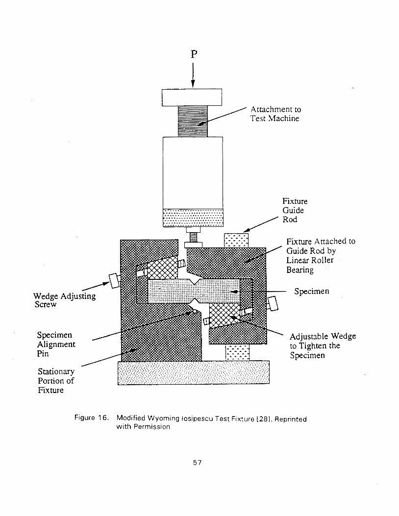
Attachment to Test Machine
I I Fixture
Fixture
Fixture Attached Guide Rod by Linear Roller Bearing
Specimen
Adjustable Wed to Tighten the Specimen
Figure 16. Modified Wyoming losipescu Test Fixture [281, Reprinted w i th Permission

It may be noted t!-.at the fixture and the test described above have also been used for
determining interlaminar shear response. Bonding of several layers are, however, required t o
obtain specimens of required size (Figure 18) .
3.5.2 Stress States and Failure Modes
Although the stress state was found t o be ideal for isotropic materials [241 (it may be
noted that the stress state is very good in crossply laminates [ I 1 I), a very complex state of
stress exists in O0 unidirectional specimens. The stresses (normalized w i th average shear
stress) in a 2 " x 0.5" specimen wi th a sharp 90° notch are shown in Figure 19, which
indicates that the stresses are nonuniform even in the test section. Shear stresses are fairly
nonuniform and low ( = 0.8) . Transverse stresses are fairly high near the notches and load
application points. A marked improvement occurs by introducing a rounded notch (.05"
radius). Shear stresses become closer to unity and the transverse stresses are reduced by a
factor of 2. Further improvement is noticed when the larger specimen (3" x 0 .75 " ) wi th a
1 20° rounded notched is used. The shear stress in the test section becomes of the order of
0.93 times the average shear stress (Figure 20) and transverse stresses are reduced further
because the load application points are moved away from the test section.
Even w i th the introduction of the rounded notch, damage initiates at the notch roots [81
causing splitting in O0 specimens (Figure 21) and the load drops at this point. The load can
be increased, however, and the final failure load is attained after the splits become
constrained as they progress towards region of lower stresses. A typical pattern of damages
in O0 specimen is shown in Figure 22, which indicates the development of more transverse
cracks, which are expected due t o shear, and can be considered t o be representative of what
may occur in a laminate or a structural component.
It may be noted that an ideal state of pure shear over a large area ( = average stress) does
not exist in O0 specimens. A small area ( = 0.1 " x 0.1 " ) in the center can possibly be
considered t o be in pure shear. A more ideal state exists in 9 0 ° specimens t291, but such
specimens fail early because of easy fracture path available (parallel t o fibers and connecting
the notches). Such a failure mode is not representative of shear failure of a lamina in a
laminate containing laminae of other orientations.
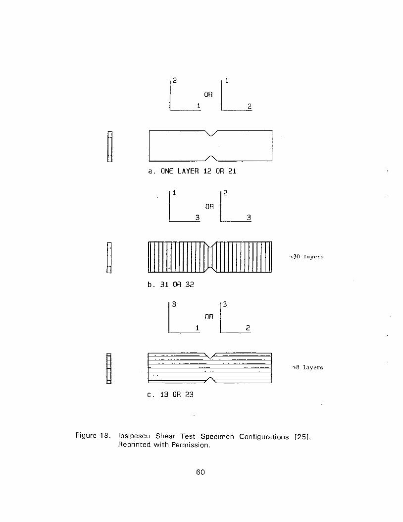
I I a . ONE LAYER 12 OR 21
\30 layers
%8 layers
Figure 18. losipescu Shear Test Specimen Configurations [251. Reprinted wi th Permission.
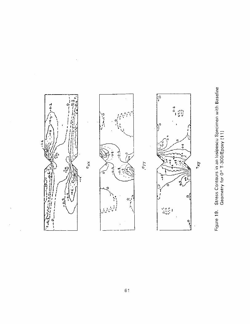
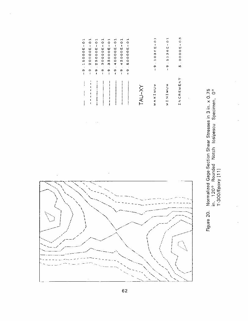
r l d d d d d d d 0 0 0 0 0 0 0 0 I I I I I I I I W W W W W W W W 0 0 0 0 0 0 0 0 0 0 0 0 0 0 0 0 0 0 0 0 0 0 0 0 l n o m o m o m o d N N m m t t u l
. . . . . . . . aa0,0,'.n'.n'.n'.n I I I I I I I I
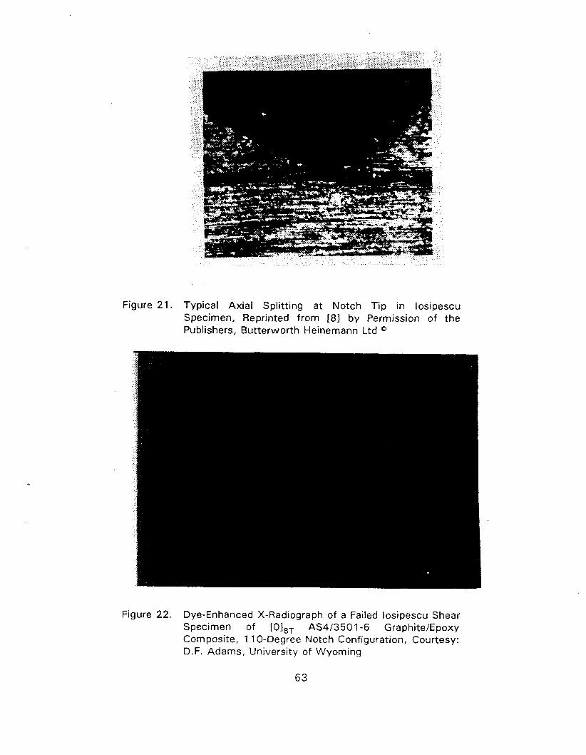
Figure 21. Typical Axial Splitting at Notch Tip in losipescu Specimen, Reprinted from 181 by Permission of the Publishers, Butterworth Heinernann Ltd 0
Figure 22. Dye-Enhanced X-Radiograph of a Failed losipescu Shear Specimen of [0IBT AS4/3501-6 Graphite/Epoxy Composite, 1 1 0-Degree Notch Configuration, Courtesy: D.F. Adams, University of Wyoming
As mentioned earliqr, crossply specimens yield better stress distributions and more realistic
failure modes, showing more distributed microcracking in the layers. Stress distribution in
quasi-isotropic layups is also good but that in the (445O) layup is worse. Factors are needed
for correct evaluation of shear stress, which is nominally defined as load per unit area of the
test section (see [ I I ] ) . Shear strengths of quasi-isotropic and (k45O) layups are high, and
serious problems arise in testing thicker specimens. On the other hand, thinner (445O)
specimens need tabs [ I 11 t o avoid local failure near loading points. Thin unidirectional
specimens may also need the use of tabs when used in the original APFB type fixture 1291.
Fiberglass tabs (0.075" thick) on the loading edges (and also on sides) have been used and
are not found t o have strong influence on the results.
Considerable inconsistency in data has been' observed by various investigators using the
losipescu specimen. With improvements in the fixture and good loading arrangements, the
test has been considered for an ASTM Standard. Round robin results have been found to be
acceptable and a standard has been approved by the D-30 Committee.
3.5.3 Data Reduction
Strains should be measured with three-element rosettes (or two 45 O gages). Back-to-back
gages may be required if there is a chance of bending, which sometimes do occur. Shear
stress is taken as the average value in the notched section (loadlarea). However, as noted
earlier, stress states in O 0 specimen are not uniform and a correction factor is required, i.e.,
0.84 and 0.93 for 90° and 120" notch, respectively, as obtained from elastic finite element
analyses. After the notch tip damage initiation and onset of inelastic strains, the stress state
becomes more uniform. Therefore, there is a dilemma in using a constant correction factor
over the entire stress-strain history.
3.5.4 Other Reauirements and Modifications
Monitoring the output from tensile and compressive ( two 45O gages) strain gages have
been suggested 1301 as a means of checking for pure shear. However, this factor is not as
important as bending and twisting effects [281. Placing the specimen into the fixture should
be done in a careful manner, and the loading faces should be ground smooth and parallel to
avoid inplane or out-of-plane bending or twisting. Soft shim materials can reduce these
effects [301. Good quality notches are needed, and these can be machined w i th proper care
[301.
A modified version of this specimen (compact in size) has been suggested for testing
specimens from filament wound cylinders [31 I . The fixtures are bonded to the specimen wi th
adhesives. It is not clear how this load transfer mechanism will work if high loads are
required.
3.6 ARCAN
3.6.1 General Descr i~ t ion of the Test Method
A biaxial stress test specimen proposed in [321 has been used by some investigators for
determining the shear properties of composites. The specimen is in the form of a circular
plate w i th t w o cutouts as shown in Figure 23 (reprinted from [21). Application of a vertical
load ( a = 0" ) produces a state of shear stress in the central notched portion which is similar
in shape t o the test section of the losipescu specimen. Load applied at an angle to the
vertical axis (y) causes generation of extensional stress in addition t o shear and, therefore,
this specimen can be used for biaxial loading as well as pure shear. Typical specimen
dimensions are given in Figure 23.
3.6.2 Stress States and Failure Modes
Shear stress states in the specimen are shown in Figure 24 for unidirectional
graphitelepoxy (fibers parallel to y-axis, see Figure 23) and glasslepoxy fabric composites [21.
I t is clear that stress gradient is hicjh in the x-direction even within the small distance
d2 (0.1 1 " ) , which is assumed as the equivalent width of the gage section [21.
Failure often occurs away from the gage section 121 because of complex stress states
slightly away from this area. Reinforcements are needed to prevent such failures and it has
been suggested [331 that except for a small test area near the notched section, the rest of the
specimen be replaced by an aluminum plate bonded to the test material (Figure 25). Stress
distribution in such a specimen has not been analyzed in detail but a similar set up has been
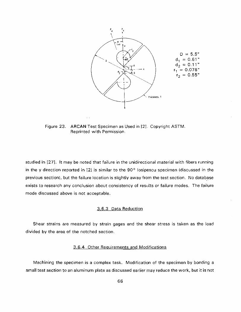
Figure 23. ARCAN Test Specimen as Used in [21. Copyright ASTM. Reprinted wi th Permission.
studied in [271. It may be noted that failure in the unidirectional material wi th fibers running
in the y direction reported in [2] is similar t o the 90° losipescu specimen (discussed in the
previous section), but the failure location is slightly away from the test section. No database
exists to research any conclusion about consistency of results or failure modes. The failure
mode discussed above is not acceptable.
3.6.3 Data Reduction
Shear strains are measured by strain gages and the shear stress is taken as the load
divided by the area of the notched section.
3.6.4 Other Requirements and Modifications
Machining the specimen is a complex task. Modification of the specimen by bonding a
small test section to an aluminum plate as discussed earlier may reduce the work, but it is not
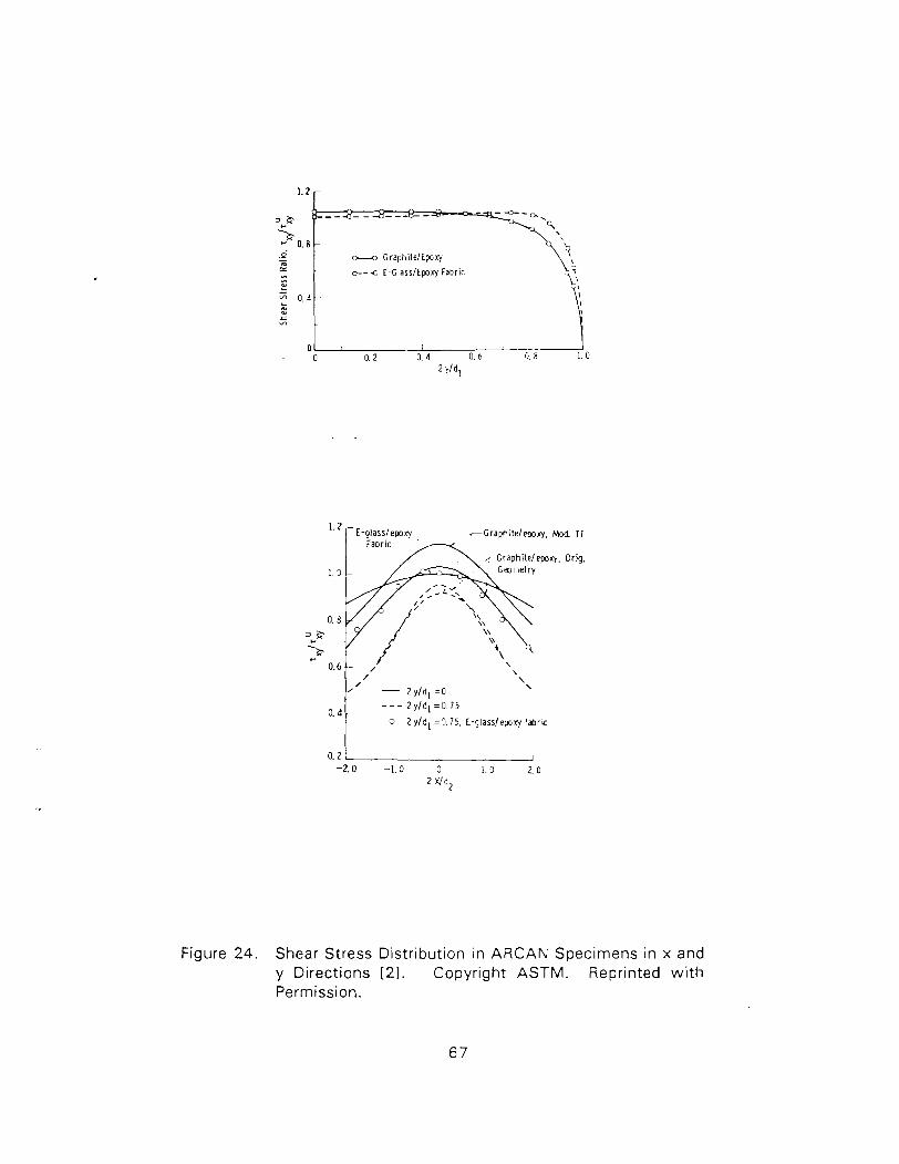
Figure 24. Shear Stress Distribution in ARCAN Specimens in x and y Directions (21. Copyright ASTM. Reprinted w i th Permission.
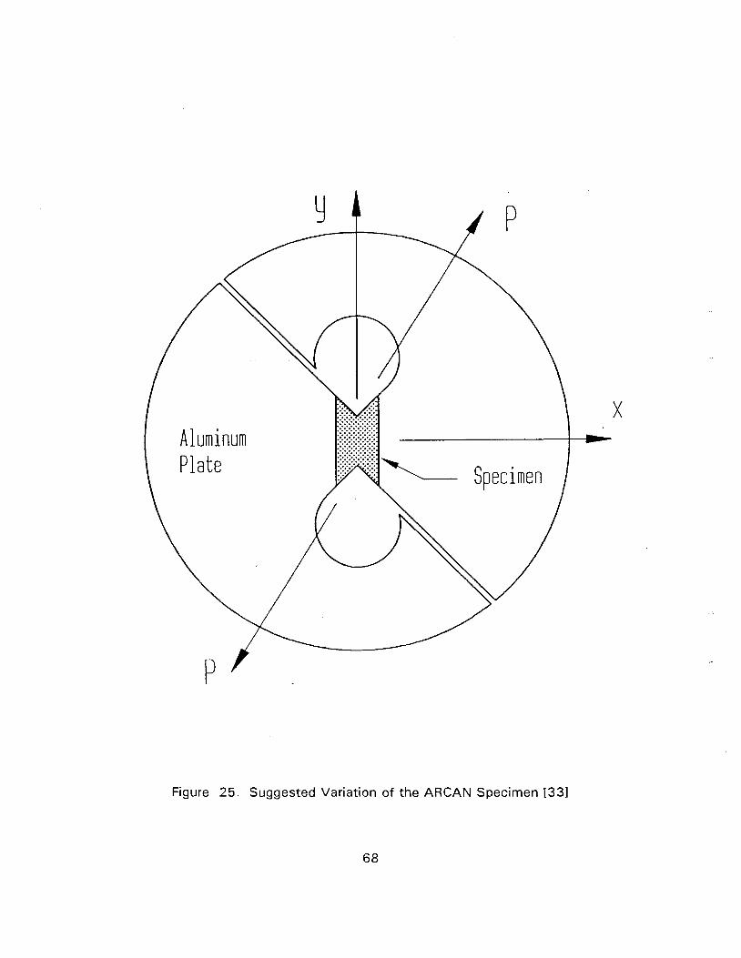
Figure 25. Suggested Variation of the ARCAN Specimen [331
68
clear whether such bonding wil l be able t o take high load levels which may he required if
fibers run perpendicular t o y-axis.
3.7 RAIL SHEAR
3.7.1 Descr i~ t ion of the Test Method
Two- and three-rail shear tests have been studied by various investigators. Tests wi th
constant thickness rails bolted t o the specimen are described in an ASTM guideline D4255
[341. A typical three-rail shear fixture wi th a specimen is shown in Figure 26. Compressive
load which is applied in this fixture is commonly preferred over tensile load. Appropriate
torque is applied t o the bolts t o avoid slipping as load is increased. Smaller specimen size is
needed when a two-rail fixture is employed. The ASTM guide suggests a bolted two-rail
fixture which may be loaded in tension or compression. Various methods have been
suggested (such as the use of abrasive paper, soft metal shims, tabs in rail areas, machining
grooves or random punching in the rails) to facilitate gripping. Even wi th the use of such
methods, bolt tightening may be needed wi th increasing load, especially when tension loads
are used. For this reason bonding the rails to the specimen (or sometimes in combination with
some bolts) has been suggested [35, 361. The specimens for a two-rail shear test are
typically 2.75" x 4 t o 6" long in size bonded to steel rails, each 1.1 25 " wide, leaving a test
section 0.5" wide between the rails. Constant thickness and tapered rails (thickness varying
from 0.75" at loaded end t o 0 .0625" at the free end, Figure 27) have been employed. A
diagonally loaded fixture (as shown in the figure on the left hand side) but w i th compressive
load is usually preferred.
3.7.2 Stress States and Failure Modes
The stress state (normalized wi th respect to the average shear stress) in a 6 " long
unidirectional specimen under tensile load wi th constant thickness rails (fibers running parallel
to rails) is shown in Figure 28 [1 11 for applied tensile load on the fixture. I t may be seen that
the shear stress is uniform over a large area in the center of the specimen. Some axial
stresses (a,, x and y axes are shown in Figure 27) do exist in the gage section. Axial,
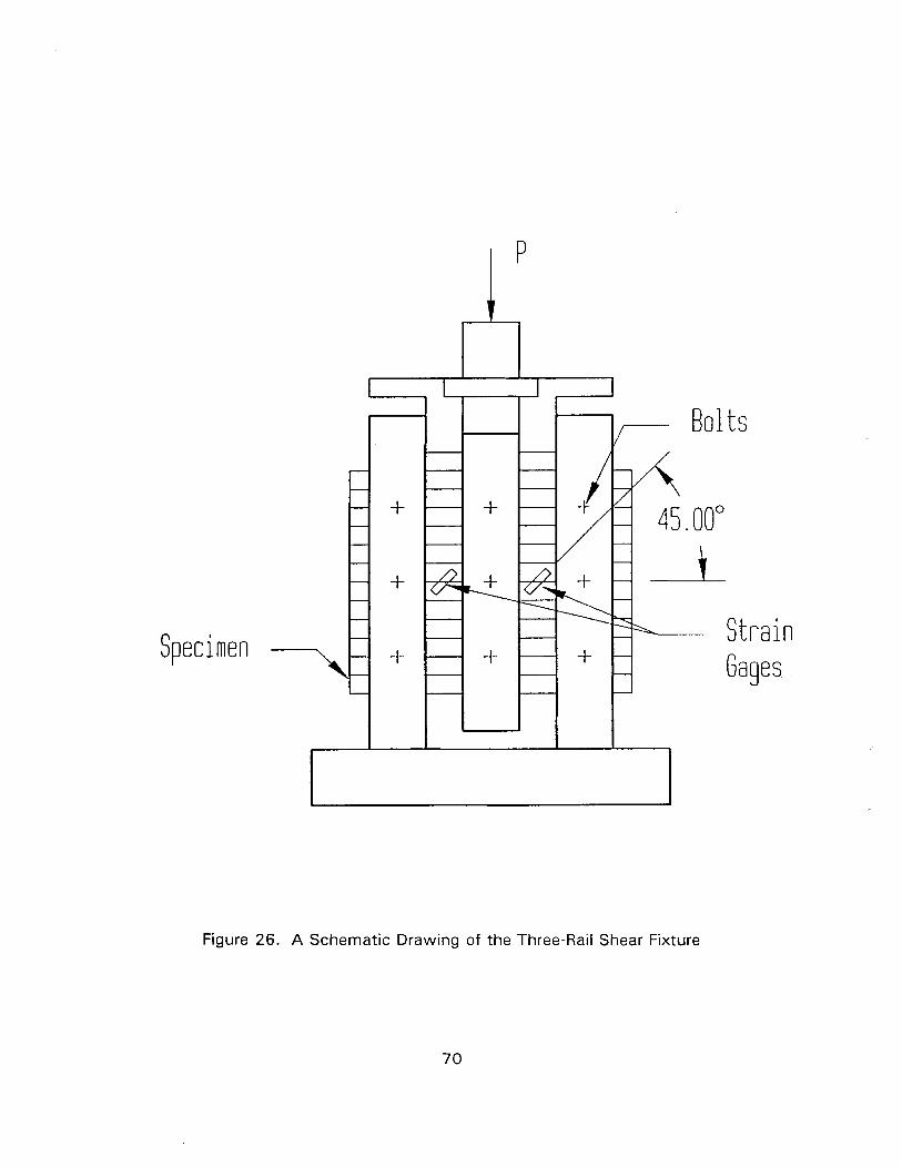
Specimen
Figure 26. A Schematic Drawing of the Three-Rail Shear Fixture
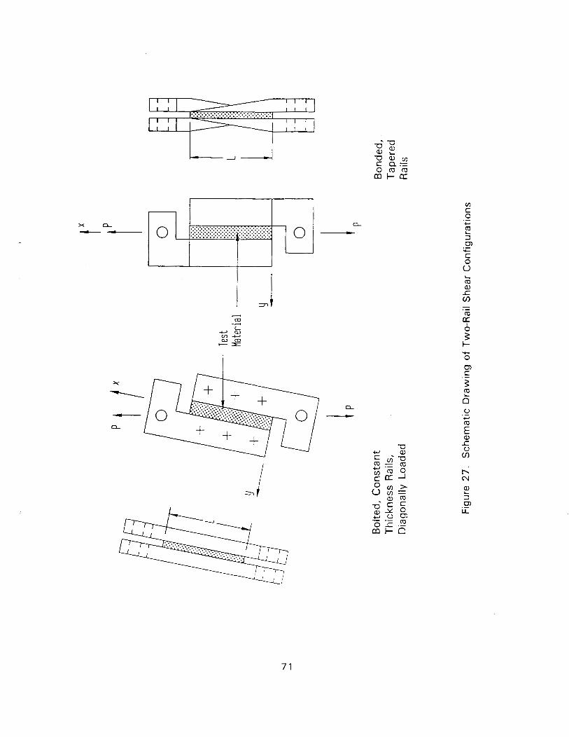
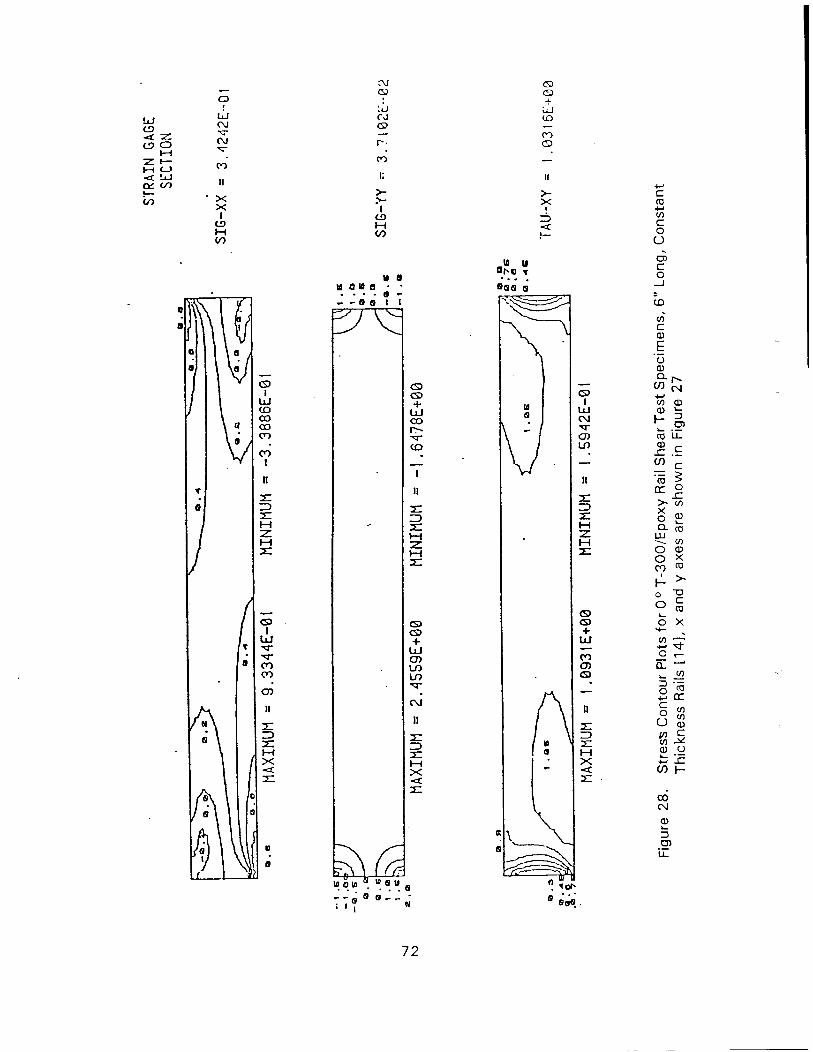
transverse and shear stress are high at all the corners. Stresses in the unloaded corners can
be reduced significantly by using tapered rails. The transverse stress (0,) variation (along the
length) near the rails for three laminates is shown in tht: figure on the lef t hand side of
Figure 29 . It may be seen that the transverse stress remains high near the loaded corner
(x=O). It has been suggested [361 that adhesive nonlinearity reduces the stresses near the
corners, so that the stress distribution is acceptable. A modif ication of the specimen in the
form of a parallelogram shape (Figure 3 0 ) has also been suggested 11 1, 141 which reduces
the stresses t o some extent in the loaded corner (Figure 29, parallelogram w i t h 4 = 60°) .
Figure 3 1 shows that the shear stresses are uniform over a large area and transverse stresses
are reduced further.
Failure in unidirectional specimens w i t h fibers parallel t o rails occurs in the form of cracks
parallel t o the fibers which cause large scatter in shear strength [371. Bolted specimens yield
more compliant response than bonded ones [351. The scatter in strength is reduced if 0 .5 "
long slots (at rail boundaries), wh ich tend t o stop unstable crack growth, are introduced a t all
corners [371. Tests w i t h fibers perpendicular t o rails (or (0190) laminates) produce failure
over a wider zone, w i t h many ply cracks, which appear t o be representative of subcritical
failures observed in individual plies under shear in a laminate (Figure 3 2 reprinted from i381).
Representative test data f rom rectangular ( 4 = 9 0 ° ) and parallelogram ( 4 = 45') shaped
specimens w i t h fibers perpendicular t o the rails are compared in Figure 6 w i t h data f rom other
shear specimens [1 11. It may be seen that the data from parallelogram specimens compare
wel l w i t h those f rom losipescu specimens. Rectangular shaped specimen data are also
acceptable, but the failure strains are a little lower. Data from rectangular and parallelogram
shaped specimens for crossply layups have also been found t o correlate wel l w i t h those from
losipescu specimens [ I 1 I . Some of these specimens showed evidence of delaminations (after
failure) between plies in addition t o individual ply cracks. Wi th compression load, some thin
specimens (parallelogram shaped ones in particular) may also show local compressive or
buckling failure near the loaded corners [ 1 11. Thicker specimens, on the other hand, may
show tensile failure (constrained cracks) at the corners which are not loaded.
Tests have also been performed on thin quasi-isotropic and ( k 4 5 ) layups. Such
specimens show signs of delaminations near a corner and compressive crushing in these
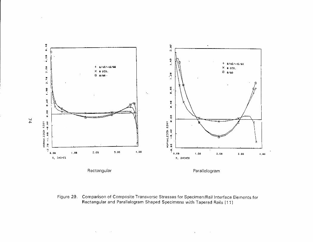
Rectangular Parallelogram
Figure 29. Comparison of Composite Transverse Stresses for SpecimenIRail Interface Elements for Rectangular and Parallelogram Shaped Specimens w i t h Tapered Rails [ I 11
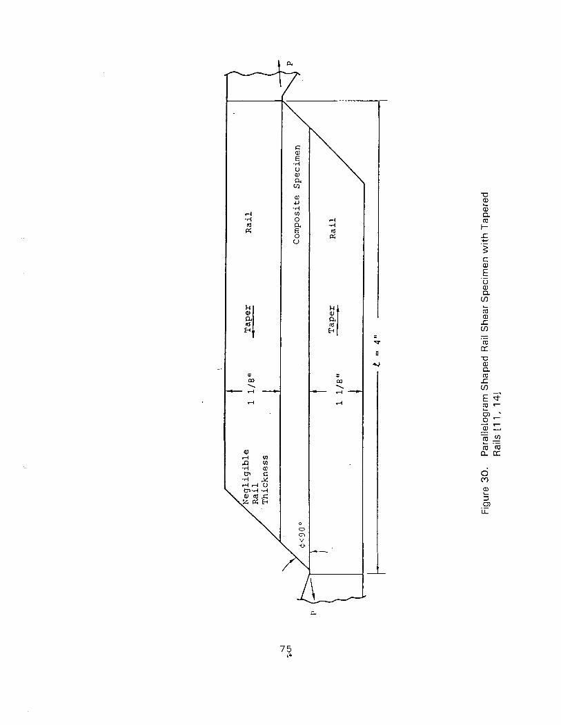
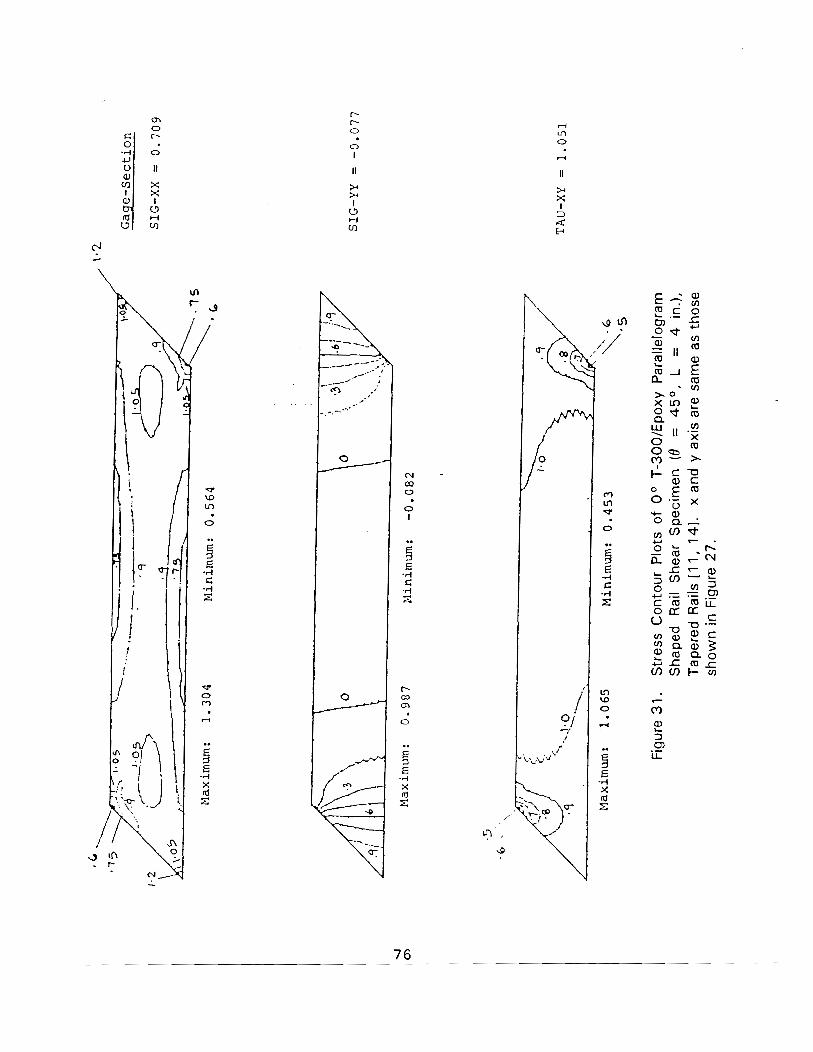
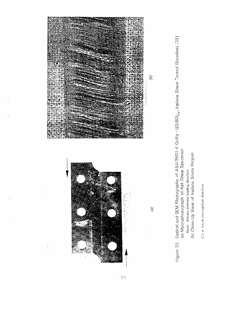
locations, possibly due t o buckling effects. Testing of thicker specimens, however, may
cause bond (or bolt) failures before specimen fracture.
Available data are not sufficient t o judge consistency of results from different sources.
A n ASTM round robin [391 did not yield consistent results. However, new specimen
modifications yield a better chance for obtaining consistent data.
3.7.3 Data Reduction
Shear strains are often measured wi th 45O gages. However, the presence of axial
stresses in the test section have been indicated by stress analyses. Therefore, strain rosettes
are recommended for calculation of shear strains. The shear stress is evaluated as the lozd
divided by the load bearing area (length of specimen x thickness). However, some correction
factors may be needed in + 4 5 or quasi-isotropic layups since the stress state may show
some nonuniformity [ I 11.
3.7.4 Other Reauirements and Modifications
No special machining is required other than cutting (and bolt hole drilling if needed).
Common adhesives are adequate. High temperature (or hot wet) testing can be a problem
because of adhesive failure. Roughening and bolting have been used [351. Thermal mismatch
between rail or specimen wil l also influence the results a t high temperatures.
Some minor misalignments in fiber placement or specimen placement may be tolerated.
However, significant fiber misalignments wil l affect the results.
A modified version of the specimen can be used for measurement of interlaminar shear
strength (Lap Shear test). In this modification rails have t o be bonded directly on t o
specimens. A parallelogram shaped specimen (similar t o the one discussed earlier) has been
used for testing carbon-carbon composites.
3.8 OFF-AXIS TENSION
3.8.1 General Desc r i~ t i on of the Test Method
Tensile testing of off-axis laminates (Figure 33 ) w i t h fiber direction making an angle of 1 O0
t o 15O t o the loading direction produces a significant amount of inplane shear stress.
Consequently th is specimen was suggested for shear testing [401. Unfortunately, tensile
normal stress perpendicular t o fibers also exists and may cause early failure. A typical tes t
specimen is a straight-sided one 0 .5 to 1 " wide x 10" long w i t h I ?h" tabbed lengths a t each
grip. Both straight and tapered tabs have been used. However, direct gripping of the tabbed
ends (clamping) creates an undesirable state of stress (in the gage section as well as at the
ends) due t o shear extension coupling (Figure 3 3 ) unless the length-to-width ratio is quite long
[ 41 I . For this reason, several at tempts have been made in designing suitable tabs and rotating
end grips t o reduce end ef fects t42-451 (on measurements of modulus and strength) as
discussed later.
3 .8 .2 Stress States and Failure Modes
The stress state in the specimen in absence of any end constraints is given by
However, i f the ends are constrained against rotation, the stress state is disturbed by
moments and shear forces a t the ends (Figure 33) . Although, these quantities reduce w i th
increasing LIW ratio, i t is imperative that hinged grips (Figure 3 3 ) should be used t o load the
specimen 142, 43, 451. Even though ro ta t~on of the clamp is permitted, the specimen is
gripped in the clamp and is not al lowed t o deform freely. For this reason, the stress state is
still not ideal.
A t tempts have also been made t o improve the performance of the specimen by changing
tab material, inclination of tab ends (not perpendicular t o specimen axis, i.e,, not square
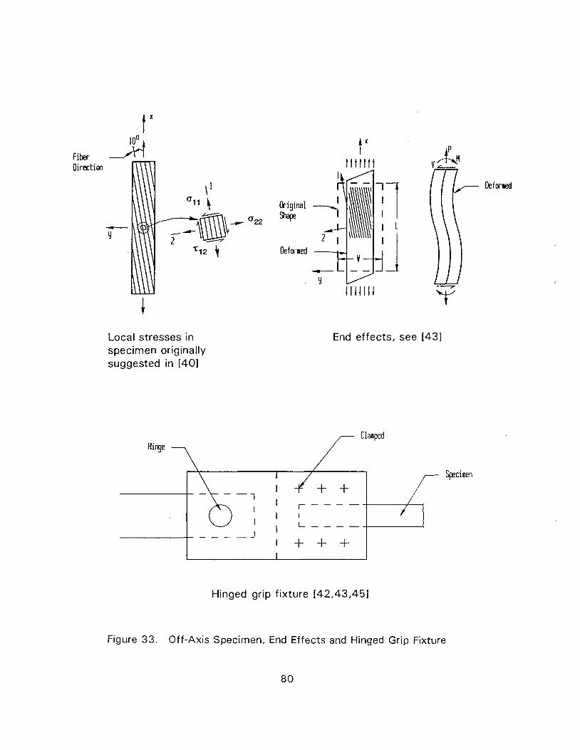
Fiber Oirectim
Local stresses in specimen originally suggested in [401
higinal shape
Deformed
End effects, see [431
Clamped Hinge
I - - - - - /
- - - - J I
I - - - - -
I + + + I
Hinged grip fixture [42,43,451
Figure 33. Off-Axis Specimen, End Effects and Hinged Grip Fixture
ended), tapered tabs and fiber alignment of tab materials. It has been found that for a given
material system and chosen off-axis angle 8 , i t is possible t o design the tabs to reduce
constraint effects [421. However, due to data scatter observed in tests (which occur due to
fiber misalignments), the beneficial effects are not confirmed by test data. The off-axis angle
itself can be chosen to maximize shear stress or minimize transverse tensile stress (not
simultaneously). It appears that off-axis angles between 1 0 and 15 degrees and fiber glass
cloth tabs w i th one reinforcement direction parallel t o fiber direction in the specimen are
appropriate.
It has been shown [43] that correction factors are required t o calculate the correct shear
stress, which is less than that given by equation (1 7) due t o end constraint. For common
graphitelepoxy composites these factors are close t o unity for 0 = 30° . For 0 = l o 0 , it
varies from 0.87 (L/W = 10) t o 0 .96 (L/W = 20). For 0 = 15O, the values are 0 .95 and
0.98, respectively.
As discussed earlier, even w i th the various modifications suggested, failure of off-axis
graphitelepoxy specimens occur at very low shear strain levels (slightly higher than the strain
at onset of nonlinearity) due t o a combination of transverse tension and shear stresses. A
straight crack develops early and separates the specimen in t w o pieces. Some materials may
perform slightly better, but i t is unlikely t o yield the desired failure in the form of many
constrained ply cracks and significant nonlinear response beyond the onset of initial damage.
Wi th appropriate correction factors, the test method is found t o yield reliable values of
modulus [ I 1, 431. Inconsistencies have been reported in previous studies because of the use
of low LNV ratios without appropriate correction factors.
Suitable adhesives are needed for bonding tabs for hot lwet testing. Testing without tabs
may also be attempted.
3.8.3 Data Reduction
Data reduction involves computation of shear strain from strain rosette data and the
correct value of the shear stress (based on elastic theory as discussed earlier).
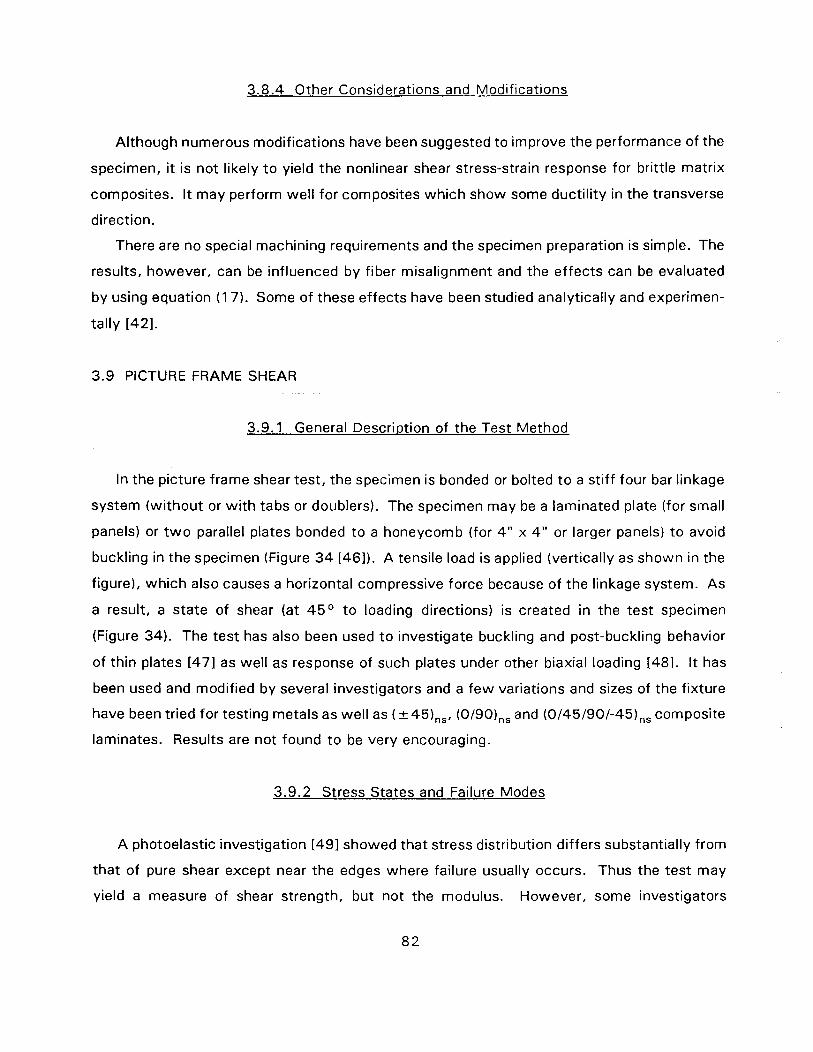
3.8.4 Other Considerations and Modifications
Although numerous modifications have been suggested to improve the performance of the
specimen, it is not likely t o yield the nonlinear shear stress-strain response for brittle matrix
composites. I t may perform well for composites which show some ductility in the transverse
direction.
There are no special machining requirements and the specimen preparation is simple. The
results, however, can be influenced by fiber misalignment and the effects can be evaluated
by using equation (1 7). Some of these effects have been studied analytically and experimen-
tally 1421.
3.9 PICTURE FRAME SHEAR
3.9.1 General Descriwtion of the Test Method
In the picture frame shear test, the specimen is bonded or bolted t o a stiff four bar linkage
system (without or w i th tabs or doublers). The specimen may be a laminated plate (for small
panels) or t w o parallel plates bonded t o a honeycomb (for 4 " x 4" or larger panels) t o avoid
buckling in the specimen (Figure 3 4 [461). A tensile load is applied (vertically as shown in the
figure), which also causes a horizontal compressive force because of the linkage system. As
a result, a state of shear (at 45O t o loading directions) is created in the test specimen
(Figure 34). The test has also been used t o investigate buckling and post-buckling behavior
of thin plates [47] as well as response of such plates under other biaxial loading 1481. I t has
been used and modified by several investigators and a few variations and sizes of the fixture
have been tried for testing metals as well as (&45),,, (0/90),, and (0/45/90/-45),, composite
laminates. Results are not found t o be very encouraging.
3.9.2 Stress States and Failure Modes
A photoelastic investigation [491 showed that stress distribution differs substantially from
that of pure shear except near the edges where failure usually occurs. Thus the test may
yield a measure of shear strength, but not the modulus. However, some investigators
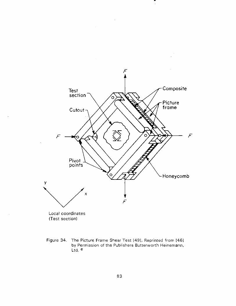
Local coordinates (Test section)
Figure 34. The Picture Frame Shear Test [491, Reprinted from [461 by Permission of the Publishers Butterworth Heinemann, Ltd. a
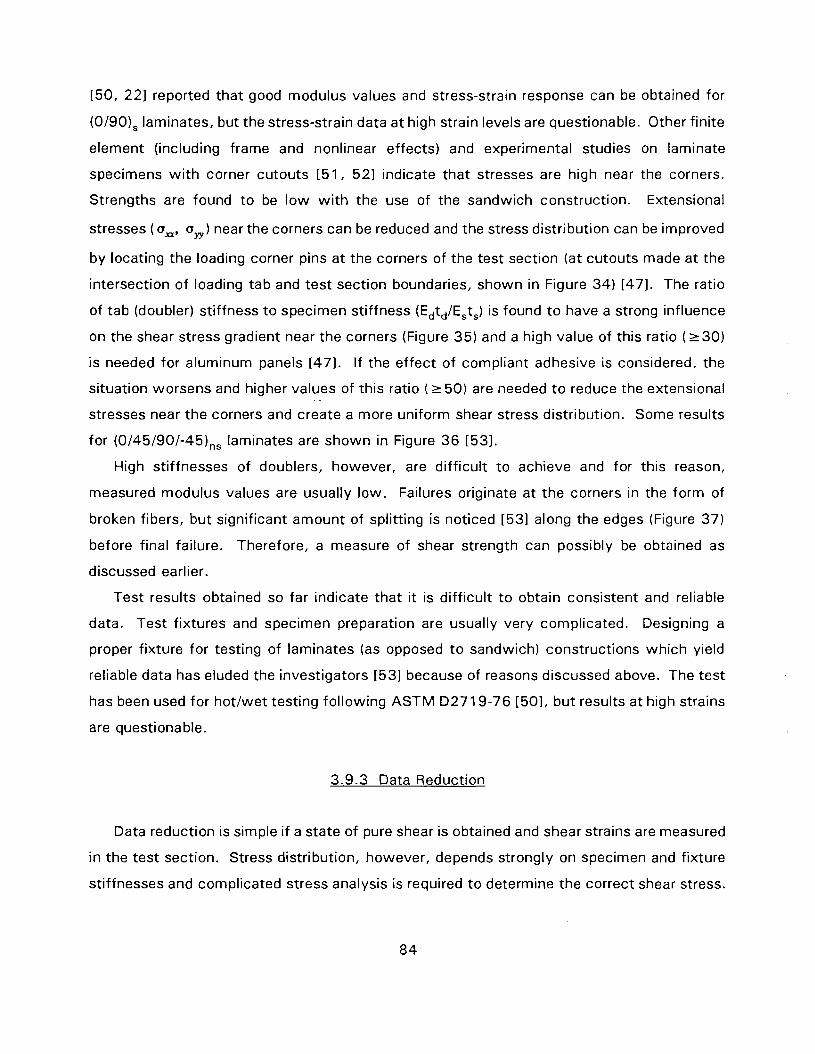
[50, 221 reported that good modulus values and stress-strain response can be obtained for
(0/90), laminates, but the stress-strain data at high strain levels are questionable. Other finite
element (including frame and nonlinear effects) and experimental studies on laminate
specimens wi th corner cutouts [51, 521 indicate that stresses are high near the corners.
Strengths are found t o be low wi th the use of the sandwich construction. Extensional
stresses (a,, a,) near the corners can be reduced and the stress distribution can be improved
by locating the loading corner pins at the corners of the test section (at cutouts made at the
intersection of loading tab and test section boundaries, shown in Figure 34) [47]. The ratio
of tab (doubler) stiffness to specimen stiffness (Edtd/Ests) is found t o have a strong influence
on the shear stress gradient near the corners (Figure 35) and a high value of this ratio (r 30)
is needed for aluminum panels [471. If the effect of compliant adhesive is considered, the
situation worsens and higher values of this ratio ( 2 50) are needed t o reduce the extensional
stresses near the corners and create a more uniform shear stress distribution. Some results
for (0/45/90/-45),, laminates are shown in Figure 3 6 [531.
High stiffnesses of doublers, however, are difficult t o achieve and for this reason,
measured modulus values are usually low. Failures originate at the corners in the form of
broken fibers, but significant amount of splitting is noticed [531 along the edges (Figure 37)
before final failure. Therefore, a measure of shear strength can possibly be obtained as
discussed earlier.
Test results obtained so far indicate that it is difficult t o obtain consistent and reliable
data. Test fixtures and specimen preparation are usually very complicated. Designing a
proper fixture for testing of laminates (as opposed t o sandwich) constructions which yield
reliable data has eluded the investigators [53] because of reasons discussed above. The test
has been used for hot lwet testing following ASTM D2719-76 [501, but results at high strains
are questionable.
3.9.3 Data Reduction
Data reduction is simple i f a state of pure shear is obtained and shear strains are measured
in the test section. Stress distribution, however, depends strongly on specimen and fixture
stiffnesses and complicated stress analysis is required t o determine the correct shear stress.
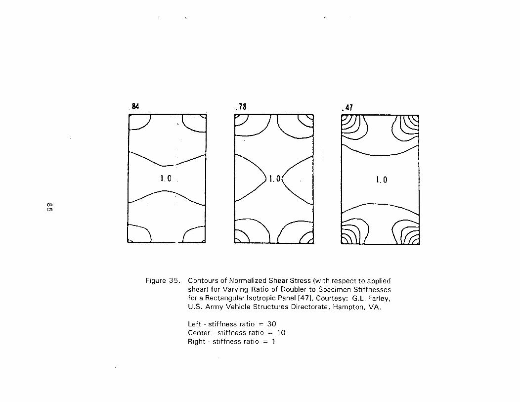
Figure 3 5 . Contours of Normalized Shear Stress (wi th respect t o applied shear) for Varying Ratio of Doubler t o Specimen Stiffnesses for a Rectangular Isotropic Panel 1471, Courtesy: G.L. Farley, U.S. Army Vehicle Structures Directorate, Hampton, VA.
Left - stiffness ratio = 3 0 Center - stiffness ratio = 1 0 Right - stiffness ratio = 1
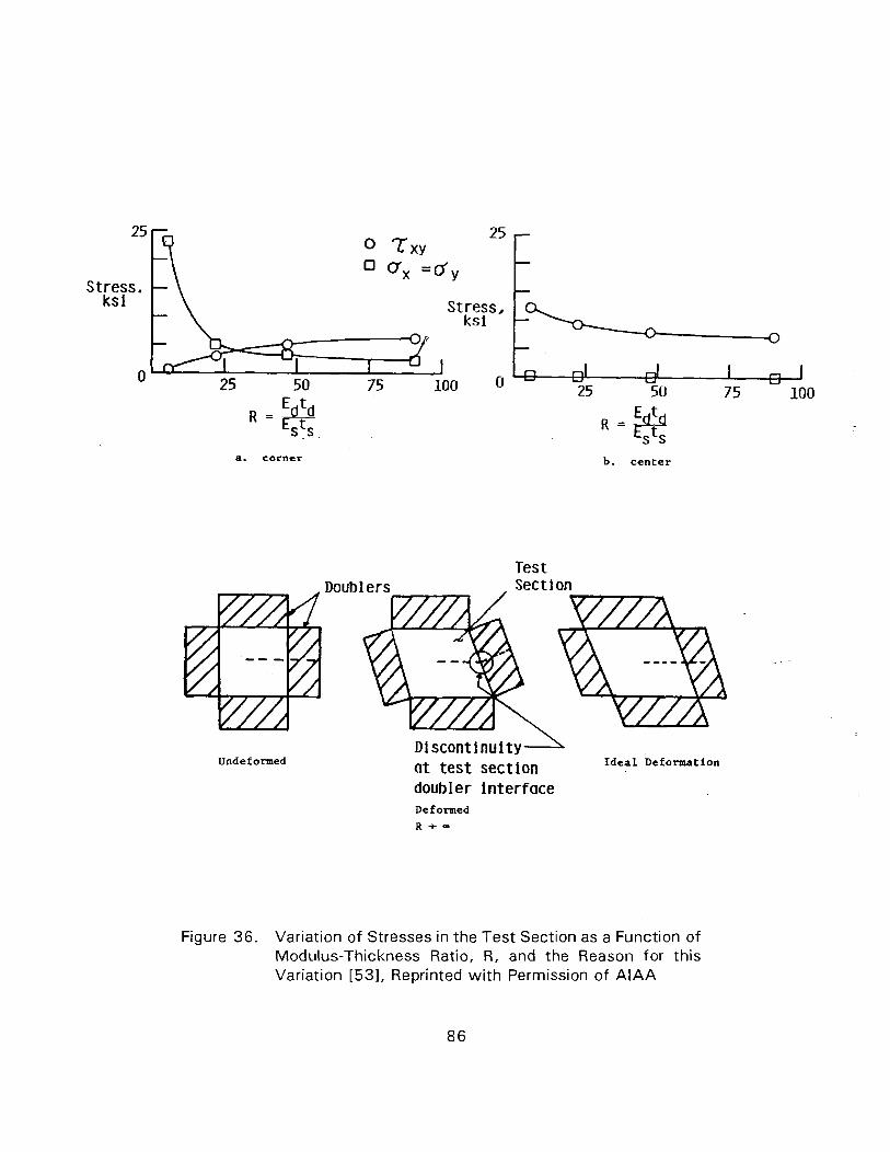
Stress. ks i
0
Stress, ks i
a. corner b . center
Test Section
Undef ormed Discontinulty at test section Ideal Deformation
doubler Interface Deformed
R + -
Figure 36. Variation of Stresses in the Test Section as a Function of Modulus-Thickness Ratio, R, and the Reason for this Variation [531, Reprinted w i t h Permission of A l A A
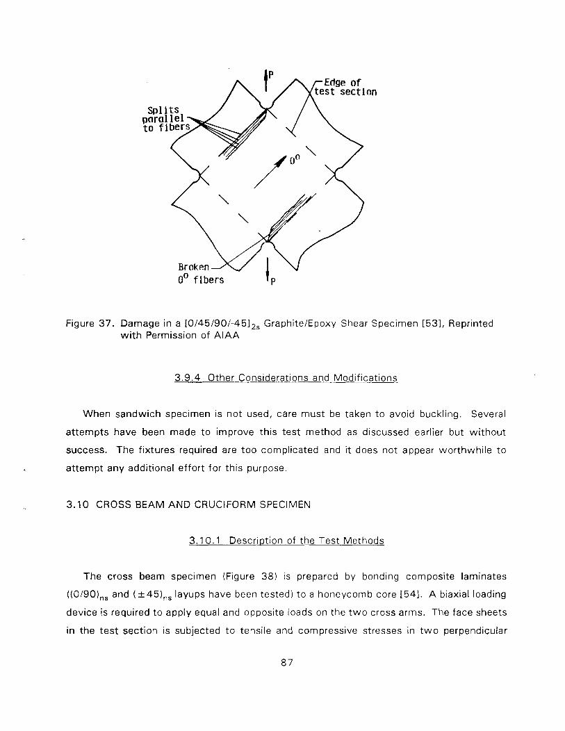
Edge of test section p%%w to fibers 4 \
fibers I P
Figure 37 . Damage in a [0/45/90/-4512, GraphiteIEpoxy Shear Specimen 1531, Reprinted w i t h Permission of A l A A
3 .9 .4 Other Considerations and Modifications
When sandwich specimen is not used, care must be taken t o avoid buckling. Several
a t tempts have been made t o improve this test method as discussed earlier but wi thout
success. The f ixtures required are too complicated and it does not appear worthwhi le t o
at tempt any additional ef fort for this purpose.
3 .10 CROSS BEAM AND CRUCIFORM SPECIMEN
3.10.1 Desc r i~ t i on of the Test Methods
The cross beam specimen (Figure 3 8 ) is prepared by bonding composite laminates
((0/90),, and (+45),, layups have been tested) t o a honeycomb core [541. A biaxial loading
device is required to apply equal and opposite loads on the t w o cross arms. The face sheets
in the test section is subjected t o tensile and compressive stresses in t w o perpendicular
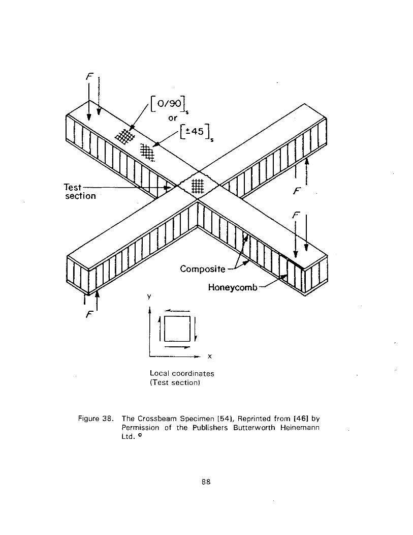
Local coordinates (Test section)
Figure 38. The Crossbeam Specimen [54], Reprinted from [461 by Permission of the Publishers Butterworth Heinemann Ltd.
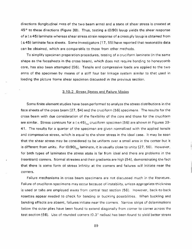
directions (longitudinal m e s of the t w o beam arms) and a state of shear stress is created at
45' t o these directions (Figure 38). Thus, testing a (0190) layup yields the shear response
of a ( k 4 5 ) laminate whereas shear stress strain response of a cross ply layup is obtained from
( k 4 5 ) laminate face sheets. Some investigators [ I 7, 551 have reported that reasonable data
can be obtained, which are comparable t o those from other methods.
To simplify specimen preparation procedures, testing of a cruciform laminate (in the same
shape as the facesheets in the cross beam), which does not require bonding t o honeycomb
core, has also been attempted [561. Tensile and compressive loads are applied t o the t w o
arms of the specimen by means of a stiff four bar linkage system similar to that used in
loading the picture frame shear specimen discussed in the previous section.
3.1 0.2 Stress States and Failure Modes
Some finite element studies have been performed t o analyze the stress distributions in the
face sheets of the cross beam [27, 541 and the cruciform [561 specimens. The results for the
cross beam wi th due consideration of the flexibility of the core and those for the cruciform
are similar. Stress contours for a (+45),, cruciform specimen [561 are shown in Figures 39-
41. The results for a quarter of the specimen are given normalized wi th the applied tensile
and compressive stress, which is equal to the shear stress in the ideal case. I t may be seen
that the shear stress may be considered t o be uniform over a small area in the center but it
is different from unity. For (0/90),, laminate, i t is usually close t o unity [27, 561. However,
for both types of laminates the stress state is far from ideal and there are problems in the
(reentrant) corners. Normal stresses and their gradients are high [541, demonstrating the fact
that there is some form of stress infinity at the corners and failures will initiate near the
corners.
Failure mechanisms in cross beam specimens are not discussed much in the literature.
Failure of cruciform specimens may occur because of instability, unless appropriate thickness
is used or tabs are employed away from central test section [56] . However, back-to-back
rosettes appear needed to check for bending or buckl~ng poss~bilities. When buckling and
bending effects are absent, failures initiate near the corners. Narrow strips of delaminations
below the outer plies have been found to extend diagonally from corner to corner across the
test section [561. Use of rounded corners (0.3" radius) has been found to yield better stress
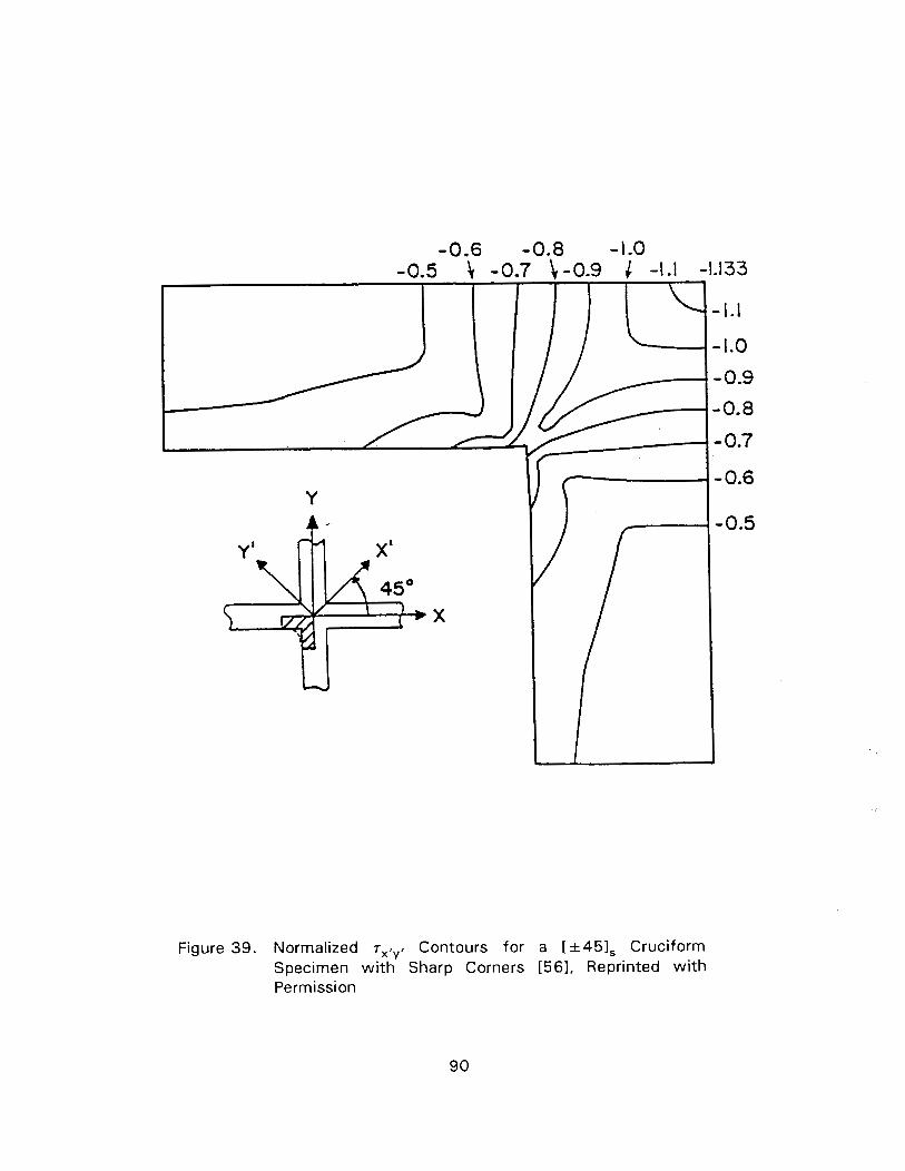
Figure 39. Normalized r,,,, Contours for a [+451, Cruciform Specimen w i t h Sharp Corners [56], Reprinted w i t h Permission
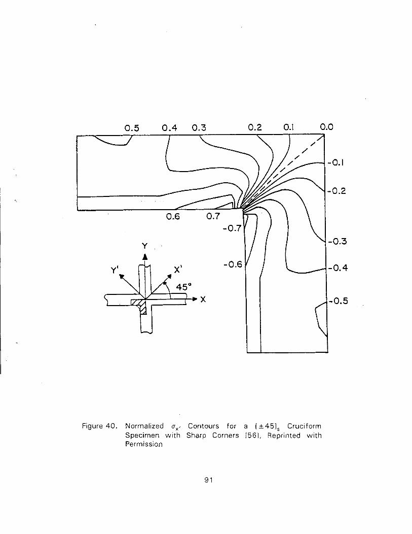
Figure 40 . Normalized a,, Contours for a [&451, Cruciform Specimen w i t h Sharp Corners 1561, Reprinted w i th Permission
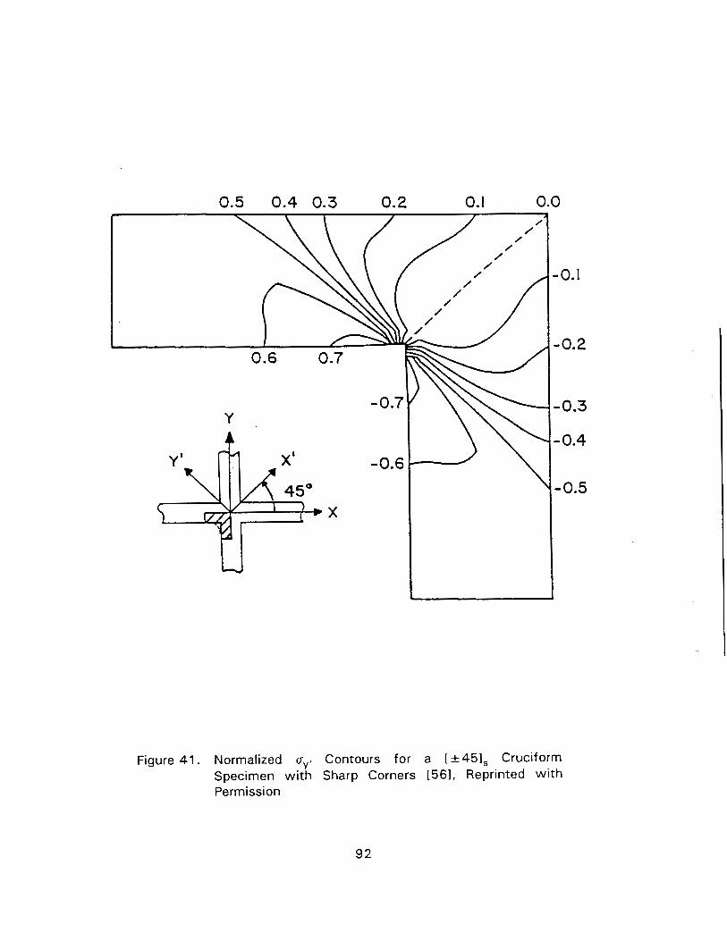
Figure 41. Normalized a,, Contours for a [+451, Cruciform Specimen wi th Sharp Corners 1561, Reprinted w i th Permission
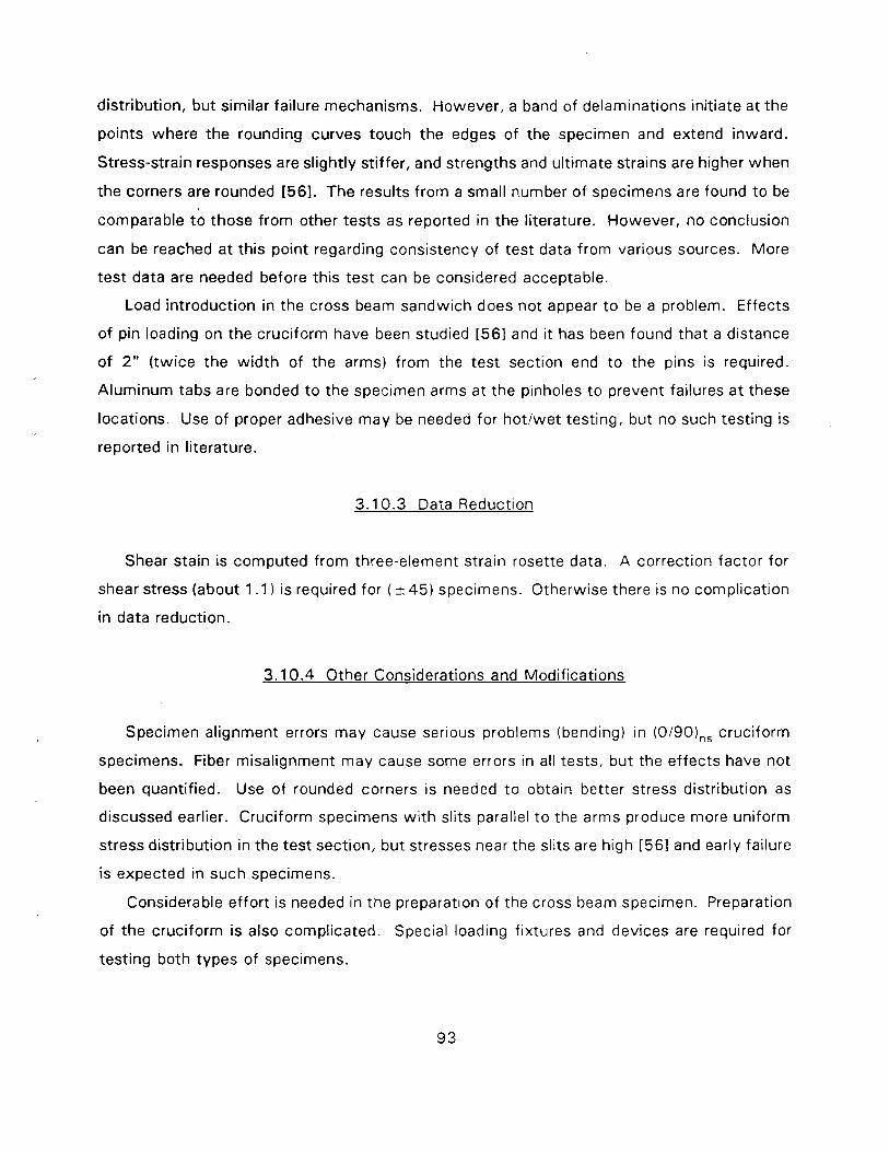
distribution, but similar failure mechanisms. However, a band of delaminations initiate at the
points where the rounding curves touch the edges of the specimen and extend inward.
Stress-strain responses are slightly stiffer, and strengths and ult imate strains are higher when
the corners are rounded [561. The results f rom a small number of specimens are found t o be
comparable tb those f rom other tests as reported in the literature. However, no conclusion
can be reached at th is point regarding consistency of test data from various sources. More
test data are needed before this test can be considered acceptable.
Load introduction in the cross beam sandwich does not appear t o be a problem. Effects
of pin loading on the cruciform have been studied [561 and it has been found that a distance
of 2" ( twice the w id th of the arms) f rom the test section end t o the pins is required.
Aluminum tabs are bonded t o the specimen arms at the pinholes t o prevent failures a t these
locations. Use of proper adhesive may be needed for ho t lwe t testing, but no such testing is
reported in literature.
3 .10.3 Data Reduction
Shear stain is computed from three-element strain rosette data. A correction factor for
shear stress (about 1 . I is required for ( k 4 5 ) specimens. Otherwise there is no complication
in data reduction.
3.1 0.4 Other Considerations and Modifications
Specimen alignment errors may cause serious problems (bending) in (0/90),, cruciform
specimens. Fiber misalignment may cause some errors in all tests, but the ef fects have not
been quantified. Use of rounded corners i s needed t o obtain better stress distribution as
discussed earlier. Cruciform specimens w i th slits parallel t o the arms produce more uniform
stress distribution in the test section, but stresses near the slits are high [561 and early failure
is expected in such specimens.
Considerable ef fort is needed in the preparation of the cross beam specimen. Preparation
of the cruciform is also complicated. Special loading fixtures and devices are required for
testing both types of specimens.
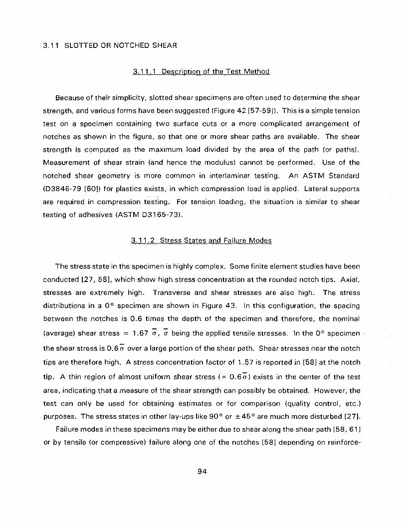
3.1 1 SLOTTED OR NOTCHED SHEAR
3.1 1 .1 Descr i~ t ion of the Test Method
Because of their simplicity, slotted shear specimens are often used t o determine the shear
strength, and various forms have been suggested (Figure 4 2 [57-591). This is a simple tension
test on a specimen containing t w o surface cuts or a more complicated arrangement of
notches as shown in the figure, so that one or more shear paths are available. The shear
strength is computed as the maximum load divided by the area of the path (or paths).
Measurement of shear strain (and hence the modulus) cannot be performed. Use of the
notched shear geometry is more common in interlaminar testing. A n ASTM Standard
(D3846-79 [60]) for plastics exists, in which compression load is applied. Lateral supports
are required in compression testing. For tension loading, the situation is similar t o shear
testing of adhesives (ASTM D 3 1 65-73).
3.1 1.2 Stress States and Failure Modes
The stress state in the specimen is highly complex. Some finite element studies have been
conducted [27, 581, which show high stress concentration a t the rounded notch tips. Axial,
stresses are extremely high. Transverse and shear stresses are also high. The stress
distributions in a O0 specimen are shown in Figure 43. In this configuration, the spacing
between the notches is 0.6 times the depth of the specimen and therefore, the nominal - -
(average) shear stress = 1.67 a, a being the applied tensile stresses. In the O0 specimen
the shear stress is 0.6; over a large portion of the shear path. Shear stresses near the notch
tips are therefore high. A stress concentration factor of 1.57 is reported in [581 at the notch
tip. A thin region of almost uniform shear stress ( = 0 .60 ) exists in the center of the test
area, indicating that a measure of the shear strength can possibly be obtained. However, the
test can only be used for obtaining estimates or for comparison (quality control, etc.)
purposes. The stress states in other lay-ups like 9 0 " or &45O are much more disturbed [271.
Failure modes in these specimens may be either due t o shear along the shear path [58 ,61 I
or by tensile (or compressive) failure along one of the notches [58 ] depending on reinforce-
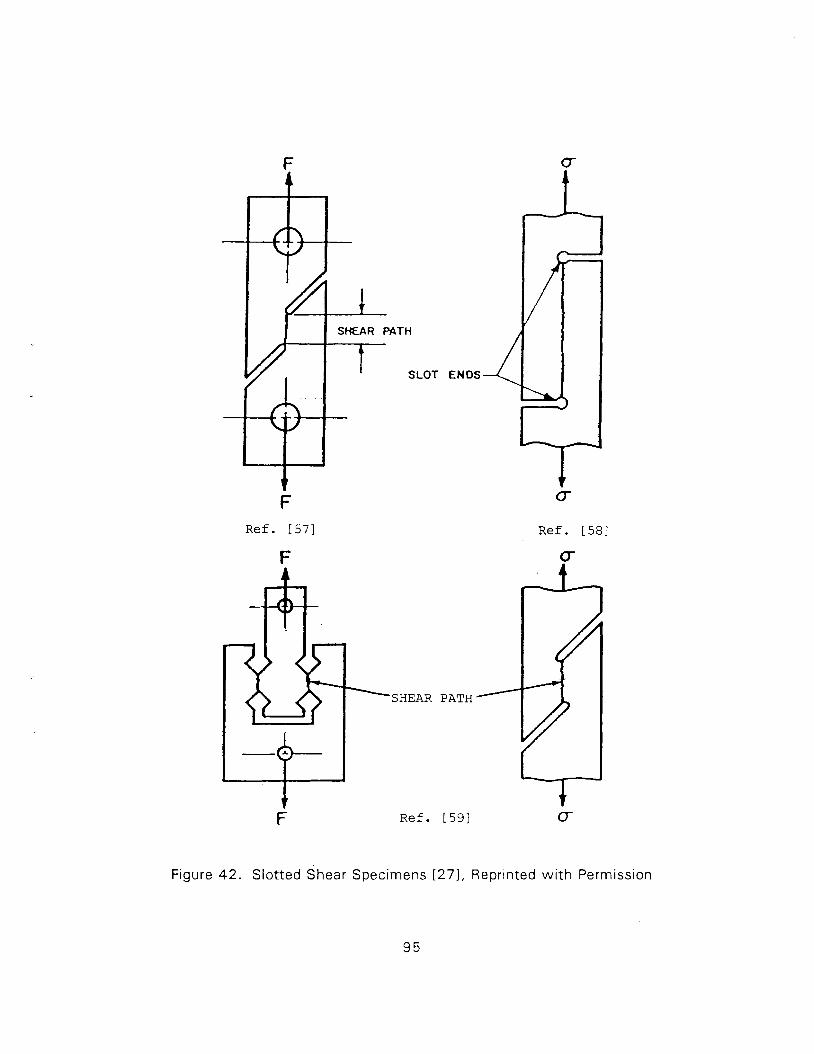
F R e f . [57]
SHEAR PATH
I SLOT ENDS
R e f . [ 5 9 ]
R e f . [58]
Figure 42. Slotted shear Specimens [ 2 7 ] , Reprinted w i t h Permission
95
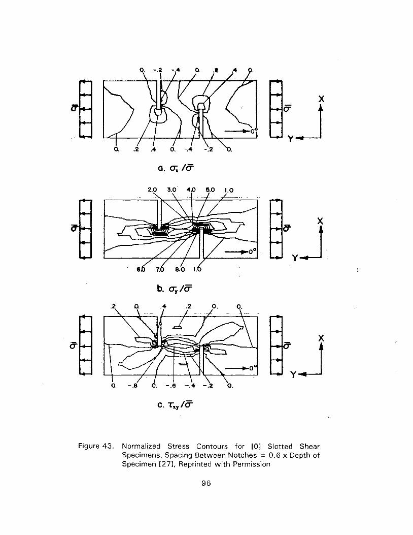
Figure 43. Normalized Stress Contours for [OI Slotted Shear Specimens, Spacing Between Notches = 0.6 x Depth of Specimen [271, Reprinted w i t h Permission
ment types. In continuous fiber systems w i th no fibers crossing the shear path (0° material
. or interlaminar tests w i th other lay-ups w i th comparatively high axial strength) shear failure
is expected. However, bending and peeling as well as tearing of the fibers are also noticed
[91. No data are available regarding consistency of results from different sources. However,
data obtained are not very reliable [91. Hot we t testing does not pose a problem.
3.1 1.3 Data Reduction
Only strength is measured and the nominal value is computed based on the area of the
shear path. A better approach based on a shear lag type analysis and the assumption that the
material is elasticlperfectly-brittle (failing in shear) is suggested in [61] . In this procedure test
data are generated for various values of P (the length of the shear path) and a curve-fitting
procedure is employed t o determine the strength, i.e. the maximum shear stress at the notch
t ip. However, it is quite likely that there are many other factors such as (i) damage induced
by axial and transverse stresses and (ii) constrained damage growth or inelastic shear
response, which possibly influence the results. A simple modification of the procedure given
in [61 I, by assuming that the shear response is of elasticlperfectly-plastic type may possibly
be attempted t o improve the data reduction procedure.
3.1 1.4 Other Considerations and Modifications
For interlaminar tests thickness (depth) of the specimen is very small and it is often
diff icult t o cut notches of required (half of the specimen) depth. A slight undercut gives
higher strength where as overcuts reduce the strength. Bending and peeling are often
observed in overcut specimens [91.
3 .12 SHORT BEAM SHEAR
3.12.1 General Descr i~ t ion of the Test Method
A three-point loaded beam is often used for determining interlaminar shear strength. An
ASTM Standard (D2344-84 [621) suggests that the span-to-depth ratio be equal t o 5 for
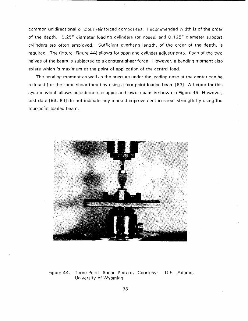
common unidirectional or c loth reinforced composites. Recommended w id th is of the order
of the depth. 0 .25" diameter loading cylinders (or noses) and 0 .125" diameter support
cylinders are of ten employed. Suff icient overhang length, o f the order of the depth, is
required. The f ixture (Figure 44) allows for span and cylinder adjustments. Each of the t w o
halves of the beam is subjected t o a constant shear force. However, a bending moment also
exists which is maximum a t the point of application of the central load.
The bending moment as wel l as the pressure under the loading nose at the center can be
reduced (for the same shear force) by using a four-point loaded beam 1631. A f ixture for this
system wh ich al lows adjustments in upper and lower spans is shown in Figure 45 . However,
test data 163, 641 do no t indicate any marked improvement in shear strength by using the
four-point loaded beam.
Figure 44. Three-Point Shear Fixture, Courtesy: D.F. Adams, University of Wyoming
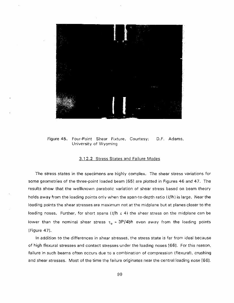
Figure 45. Four-Point Shear Fixture, Courtesy: D.F. Adams, University of Wyoming
3.1 2.2 Stress States and Failure Modes
The stress states in t he specimens are highly complex. The shear stress variations for
some geometries of the three-point loaded beam t651 are plotted in Figures 4 6 and 47 . The
results show tha t the wel lknown parabolic variation of shear stress based on beam theory
holds away f rom the loading points only when the span-to-depth ratio (Q/h) is large. Near the
loading points t he shear stresses are maximum not a t the midplane but a t planes closer t o the
loading noses. Further, for short spans (e/h < 4 ) the shear stress on the midplane can be
lower than t he nominal shear stress so = 3P/4bh even away f rom the loading points
[Figure 471.
In addition t o the differences in shear stresses, the stress state is far f rom ideal because
of high flexural stresses and contact stresses under the loading noses [661. For this reason,
failure in such beams often occurs due t o a combination of compression (flexural), crushing
and shear stresses. Mos t of the t ime the failure originates near the central loading nose [661.
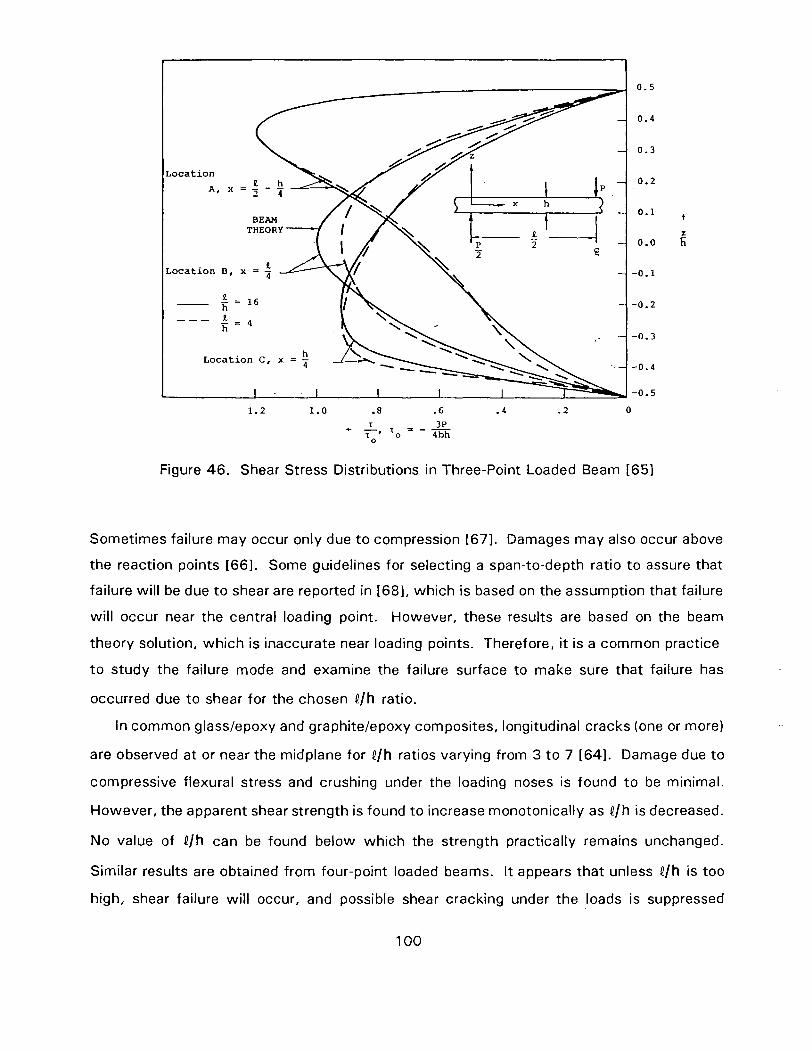
Location
Location 8, x = 7 -
-
Figure 46. Shear Stress Distributions in Three-Point Loaded Beam 1651
Sometimes failure may occur only due t o compression 1671. Damages may also occur above
the reaction points [661. Some guidelines for selecting a span-to-depth ratio t o assure that
failure will be due t o shear are reported in [68], which is based on the assumption that failure
will occur near the central loading point. However, these results are based on the beam
theory solution, which is inaccurate near loading points. Therefore, it is a common practice
t o study the failure mode and examine the failure surface to make sure that failure has
occurred due to shear for the chosen Q/h ratio.
In common glasslepoxy and graphitelepoxy composites, longitudinal cracks (one or more)
are observed at or near the midplane for Q/h ratios varying from 3 t o 7 [641. Damage due to
compressive flexural stress and crushing under the loading noses is found t o be minimal.
However, the apparent shear strength is found to increase monotonically as Q/h is decreased.
No value of Qlh can be found below which the strength practically remains unchanged.
Similar results are obtained from four-point loaded beams. I t appears that unless P/h is too
high, shear failure wil l occur, and possible shear cracking under the loads is suppressed
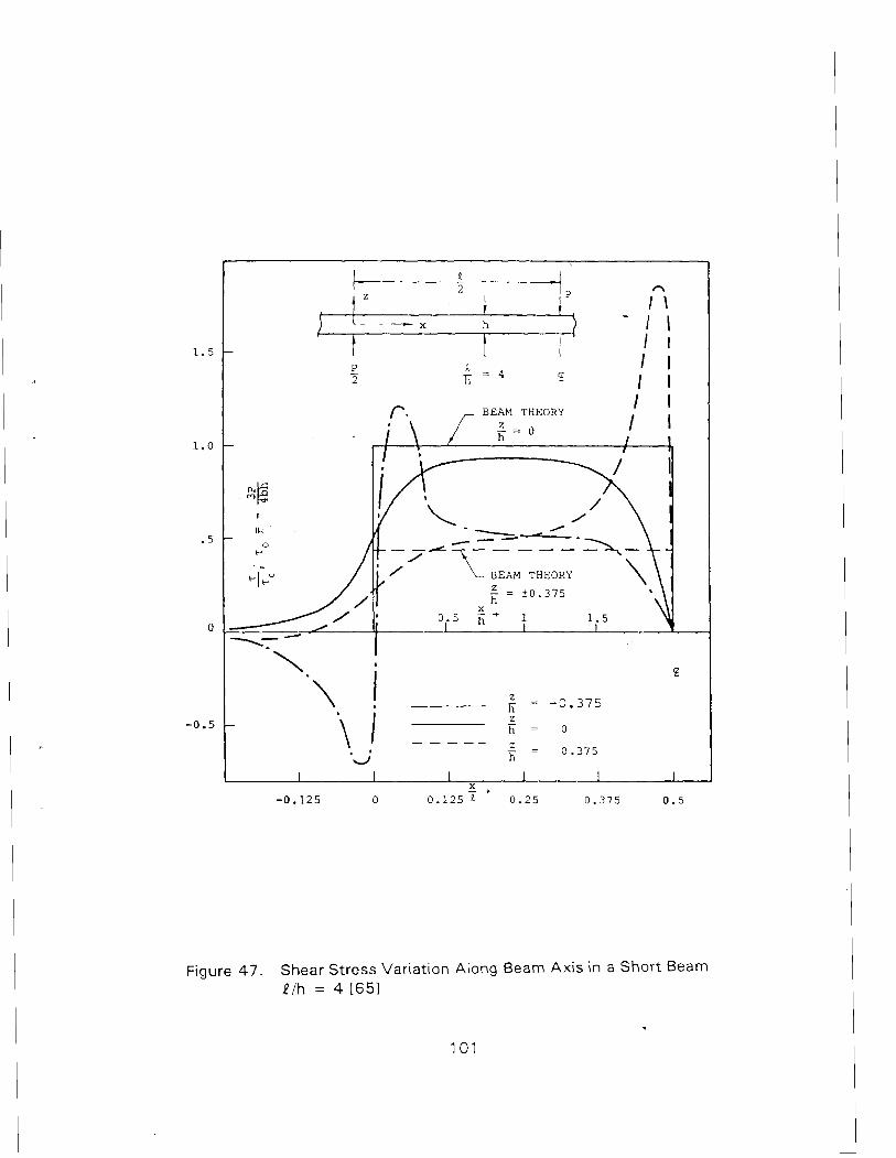
r . BEAM THEORY 1
Figure 47. Shear Stress Variation Along Beam Axis in a Short Beam P/h = 4 [651
because of high compressive stresses. Further, as stress analyses [Figure 471 suggest, the
shear stress away f rom the loads becomes lower than the nominal value when the beam
becomes shorter and therefore, the strength increases. Therefore, very short lengths are also
no t desirable in order t o obtain the shear strength. Also, testing of very short beams should
be avoided since only a very small volume of material wi l l be subjected t o the desired stress
state.
Tests have also been conducted t o determine the ef fects of the loading noses as wel l as
width-to-depth ratio [641. I t has been observed that for common unidirectional materials
width-to-depth ratio up t o 6 may be employed even though analyses [681 suggest that W/h
should be less than 3 t o insure that shear stresses are not far of f f rom beam theory solutions.
However, the ratio should be of the order of uni ty w h e n testing angle ply (*€I) laminates.
Variations in the diameters of the loading noses are no t found t o have much influence on the
apparent shear strength unless they are too small 1641.
It has been suggested 1631 that, for the same ratios of the geometric dimensions, testing
a thicker specimen is desirable t o reduce the contact stresses under loading noses. However,
test data indicate an increase in specimen thickness lowers the apparent shear strength 1641,
possibly due t o the likelihood of having more critical f l aws in a larger volume of material.
In general, the results are found t o be consistent even f rom different sources provided the
geometry of the specimen is the same. For reasons discussed earlier (and based on test data
reported in literature) Qlh ratio should not be too high or too low. Values of the order of 5 t o
6 for 0' graphite/epoxy and 3 t o 4 for O 0 glass/epoxy may be adequate. Stress analyses are
needed t o determine the elh ratio so that the nominal shear stress is recovered (away from
the loads) for a given lay-up. Confirmation of shear failure f rom examination of failure
surfaces is essential.
Ho t w e t testing does not pose a problem. However, in materials such as thermoplastics
(and i n some thermosets), large deformations may occur before failure, and in such cases
definit ion of strength becomes a problem, since stress-strain response is usually not
measurable. Measurement of load versus deformation data and a method t o back out the
shear response f rom deflection due t o shear may be a w a y out of this problem, but accurate
deflection measurement appears diff icult.
3.1 2.3 Data Reduction
Data reduction based on nominal shear stress calculated from beam theory is simple.
However, as discussed earlier, this approach gives only a measu:2 of the strength since the
stress state is highly complex.
3 .1 2.4 Other Considerations and Modif ication
The four-point beam test discussed earlier has been studied as a possible modification.
Test data reported in literature, however, do not show that this modif ication yields more
reliable data. Wi th proper geometric dimensions, the test is adequate for quality control
purposes.
3 .13 OTHER TESTS
3.1 3.1 General Description of the Test Methods
Various other tests have been proposed for measurement of shear modulus or strength.
Some of them are discussed next. However, none of these tests has gained acceptance in
the composites community.
Plate Twis t - Square f lat plates (Figure 4 8 ) are used t o determine the shear modulus. T w o
upward forces are applied at the ends of a diagonal whereas t w o downward forces are applied
at the other t w o corners. Deflection measurements are used t o compute the modulus.
Extreme care is needed in preparation of the sample and in load-deflection measurements.
A S T M D3044-76 for plywood provides the details of the test. I t has been used t o determine
the shear modulus of unidirectional materials (221. There are, however, problems, since large
deformations have significant influence on the response and the corners are susceptible t o
damage. In addition, warpage during curing can influence the deflection [691.
Four-Point R i n ~ Tw is t - A four-point loaded circular beam of constant cross section
undergoes a significant amount of deflection due t o torsion (Figure 4 9 (701). Measurement
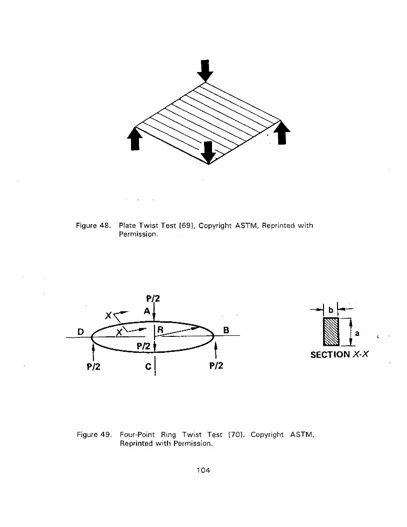
Figure 48. Plate Twist Test 1691, Copyright ASTM, Reprinted wi th Permission.
SECTION X-X
Figure 49. Four-Point Ring Twist Test [701, Copyright ASTM, Reprinted wi th Permission.
of total deflection and subtraction of bending deflecting yields a measure of the shear modulus
of the unidirectional beam material. The test is suitable if the material is available in tube or
ring form [701.
Split Rincl Shear - A split ring (Figure 50) is subjected to equal and opposite forces at the
split. Computed bending deflection is subtracted and the result is used t o compute the shear
modulus [69]. The test is useful for materials available in tube or ring form.
Biaxial Loadina (Tension-Com~ression) of a Slotted C o u ~ o n - A tensile coupon containing
slots (along the center line) parallel to loading direction is simultaneously subjected t o
compression on its edges (Figure 5 1 [54, 7 1 I ) . This causes equal tensile and compressive
stresses over a large portion of the coupon [54, 711 and a state of pure shear at 45'. The
axially oriented slots insure that the compressive load is transferred through the central test
section. Without slots the load wil l diffuse and distribute in an unknown manner. Although
the test should be able to yield the complete stress strain response, only modulus and
strength values are reported [ 7 l I . 0 ° , (0/90), ( +45) , ( 0 / + 4 5 ) and (0 /+45 /90 ) layups have
been tested. Finite element calculations [71 I show that shear stresses at the center are
within 2 % of nominal value, but there is some stress concentration (10%) at the slot end.
The process of biaxial loading is, however, complicated, since the tensile specimen has t o be
installed in a pin guided transverse compression fixture [71 I. For this reason this test has not
been used by any other investigator.
Block Shear - Single as well as double block shear tests (Figure 52) have been employed
by some investigators 172, 731. The stress state, however, is complex. It can possibly yield
qualitative data.
LaD Shear - A measure of strength may be obtained [74, 751, but the stress state is
complex and failure is caused by combined action of peel and shear stresses (Figure 53) .
Button Torsion - A specimen in the form of a button is bonded t o fixtures and a torsional
moment is applied. A possible loading arrangement [741 is shown in Figure 54. Stress state
is complex and singularities exist at the bond zone boundary.
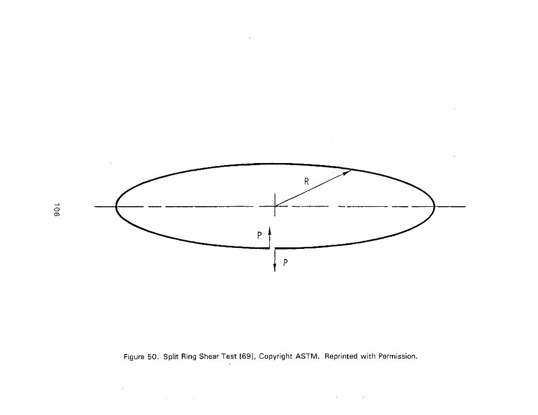
Figure 50. Split Ring Shear Test [691, Copyright ASTM. Reprinted wi th Permission.
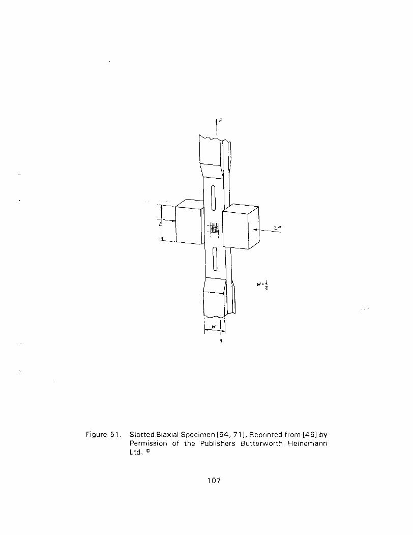
Figure 5 1 . Slotted Biaxial Specimen [54, 7 1 I, Reprinted from [461 by Permission of the Publishers Butterworth Heinemann Ltd.
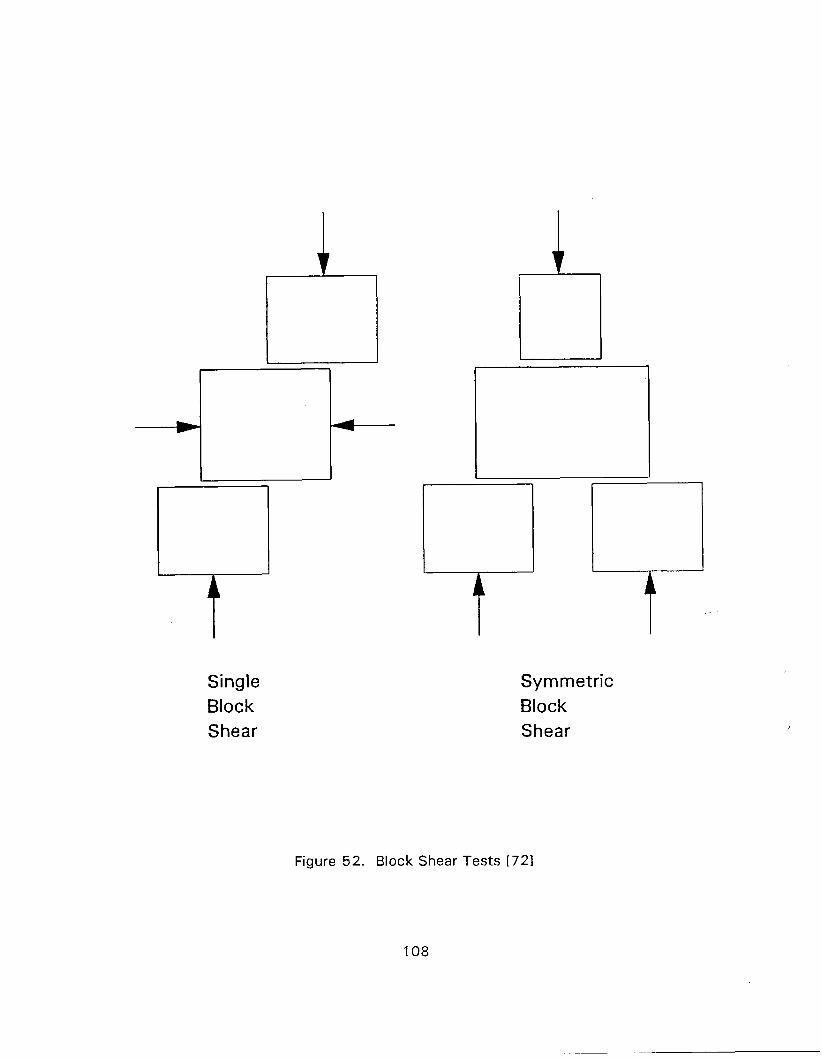
Single Block Shear
Symmetric Block Shear
Figure 52. Block Shear Tests [721
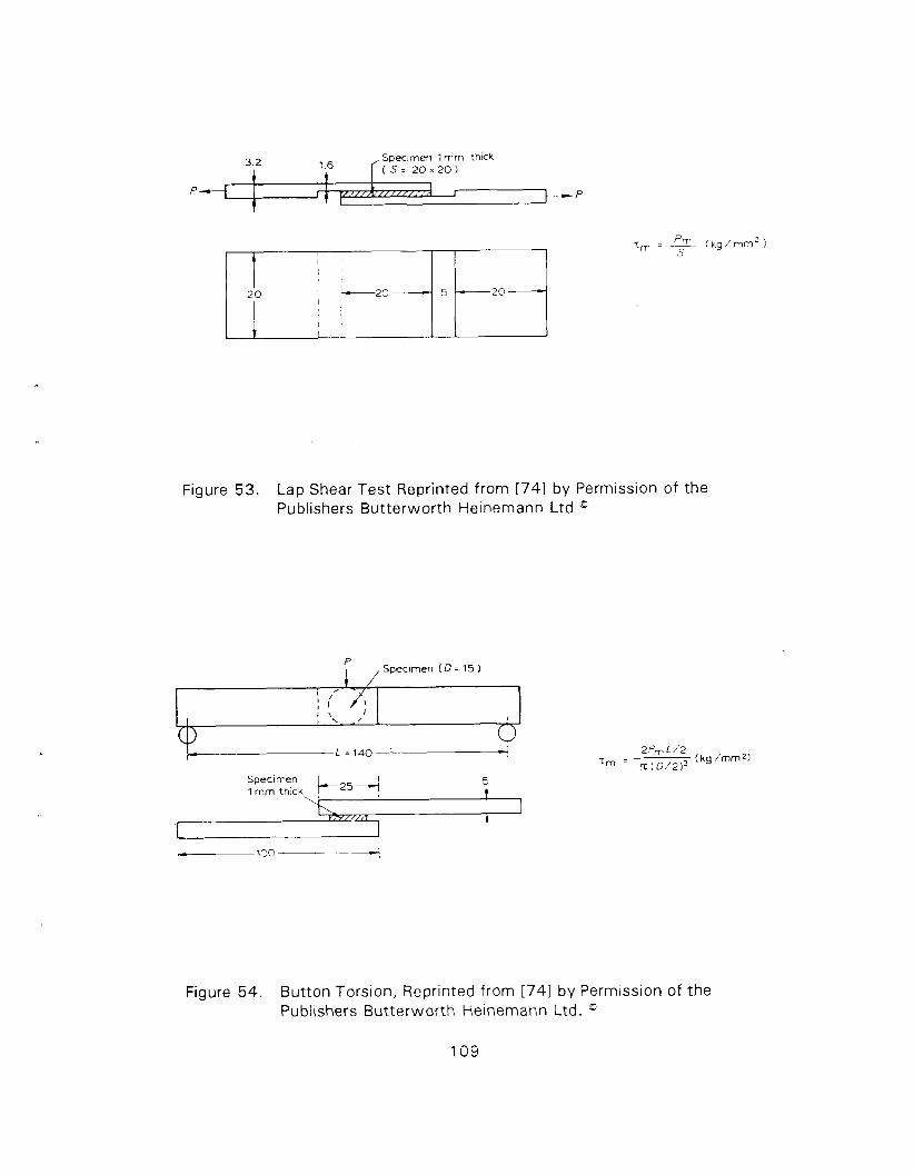
Figure 53. Lap Shear Test Reprinted from [741 by Permission of the Publishers Butterworth Heinemann Ltd
if , Specimen ( D = 15 )
Specimen 5
\ ; t 1
Figure 54. Button Torsion, Reprinted from [74 ] by Permission of the Publishers Butterworth Heinemann Ltd. "
109
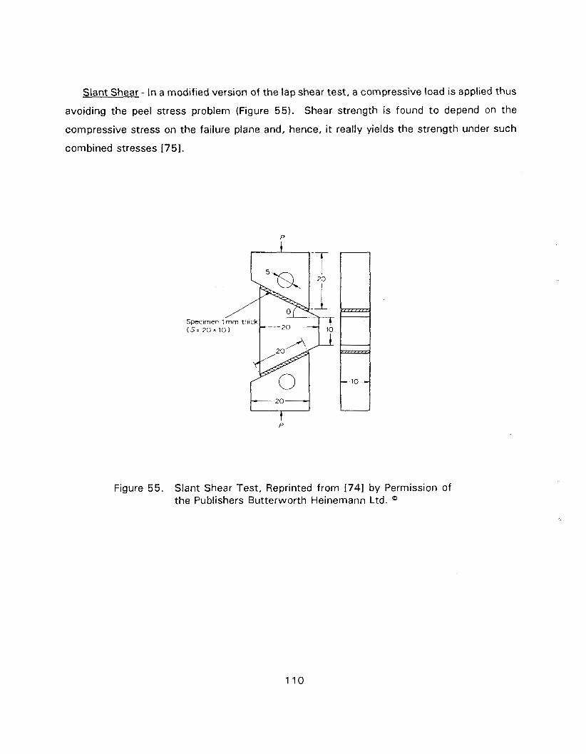
Slant Shear - In a modified version of the lap shear test, a compressive load is applied thus
avoiding the peel stress problem (Figure 55). Shear strength is found t o depend on the
compressive stress on the failure plane and, hence, it really yields the strength under such
combined stresses [751.
Figure 55. Slant Shear Test, Reprinted from 1741 by Permission of the Publishers Butterworth Heinemann Ltd.
REFERENCES
(References marked w i th an * are also summarized in the Bibliography)
Bucinell, R., "Interim JANNAF Test Method for In-Plane Shear Properties of Unidirec-
tional FiberIResin Composite Cylinders", Interim Report for MIL-HDBK-17, AMTL
Contract DAAL04-89-C-0023, 1991.
Marloft, R.H., "Finite Element Analysis of Bi-Axial Stress Test Specimen for Graph-
ite/Epoxy and Glass FabricIEpoxy Composites", ASTM STP 787, pp. 34-49, 1982.
Whitney, J .M. and Halpin, J .C., "Analysis of Laminated Anisotropic Tubes under
Combined Loading", Journal of Composite Mater~als, Vol. 2, pp. 360-367, 1968.
Pagano, N.J. and Whitney, J.M., "Geometric Design of Composite Cylindrical
Characterization Specimens", Journal of Composite Materials, Vol. 4, pp. 360-378,
1970.
Rizzo, R.R. and Vicario, A.A., " A Finite Element Analysis for Stress Distribution in
Gripped Tabular Specimens", ASTM STP 497, pp. 68-88, 1972.
Foley, G.A., Roylance, M.E., and Houghton, W.W., "Use of Torsion Tubes to
Measure In-Plane Shear Properties of Filament Wound Composites", ASTM STP
1003, pp. 208-223, 1989.
Swanson, S.R., Toombes, G.R., and Beckwith, S.W., "In-Plane Shear Properties of
Composites Using Torsion Tests of Thin Walled Tubes", Proc. 29th SAMPE
Symposium, pp. 567-577, 1984.
Swanson, S.R., Messick, M., and Toombes, C.R., "Comparison of Torsion Tube and
losipescu In-Plane Shear Test Results for a Carbon Fiber Reinforced Epoxy
Composite", Composites, Vol. 16, pp. 220-224, 1985.
Chiao, C.C., Moore, R.L., and Chiao, T.T., "Measurements of Shear Properties of
Fiber Composites, Part 1 . Evaluation of Test Methods", Composites, Vol. 8, pp.
161 -1 69, 1977.
Phillips, D.C and Scott, J.M., "The Shear Fatigue of Unidirectional Composites",
Composites, Vol. 8, pp. 233-236, 1977.
Chatterjee, S.N., Wung, E.C.J., Yen, C.F., Ramnath, V., Kessler, J.A., and Adarns,
D.F., "Composite Specimen Design Analysis, Vol. I: Analytical Studies, Vol. II:
Experimental Effort", MTL TR 91 -5, 1991.
Lenoe, E.M., Knight, M., and Schoene, C., "Preliminary Evaluation of Test Standards
for Boron Epoxy Laminates", ASTM STP 460, pp. 122-1 39, 1969.
Sumsion, H.T. and Rajapakse, Y.D.S., "Simple Torsion Test for Determining the
Shear Moduli of Orthotropic Composites", Composite Technology Review, Vol. 1,
p. 8, 1979.
Ramnath, V. and Chatterjee, S.N., "Composite Specimen Design Analysis", MSC
TFR 1701 /1703, AMTL Contract DAAG46-85-C-0058, 1986.
Chatterjee, S.N. and Buesking, K.W., "Elasto-Plastic Torsion - A Variational
Formulation and Incremental Solution", in Advances in Aerospace Structures and
Materials, Proc. ASME Winter Annual Meeting, AD-01, ASME, New York, pp. 231-
237, 1981.
"Standard Practice for In-Plane Shear Stress-Strain Response of Unidirectional
Polymer Matrix Composites", ASTM Standard D35 18-9 1 , American Society for
Testing of Materials, Philadelphia, PA, 1991 .
Petit, P.H., "A Simplified Method of Determining the In-Plane Shear Stress-Strain
Response of Unidirectional Composites", ASTM STP 460, pp. 83-93, 1969.
Rosen, B.W., "A Simple Procedure for Experimental Determination of the Longitudi-
nal Shear Modulus of Unidirectional Composites", Journal of Composite Materials,
Vol. 6, pp. 552-554, 1972.
Hahn, H.T., "A Note on the Determination of the Shear Stress Strain Response of
Unidirectional Composites", Journal of Composite Materials, Vol. 7, pp. 383-386,
1973.
Kellas, S. and Morton, J., "Scaling Effects in Angle-Ply Laminates", NASA
Contractor Report 4423, February, 1992.
Kellas, S., Morton, J., and Jackson, K.E., " A n Evaluation of the + 4 5 Tensile Test
for the Determination of the In-Plane Shear Strength of Composite Materials", Proc.
ICCM VIII, 1991.
Terry, G., " A Comparative Investigation of Some Methods of Unidirectional, In-Plane
Characterization of Composite Materials", Composites, Vol. 10, pp. 233-237,1979.
Sim, D.F., "In-Plane Shear Stress Strain Response of Unidirectional Composite
Materials", Journal of Composite Materials, Vol. 7, pp. 124-1 28 , 1973 .
losipescu, N., "New Accurate Procedure for Single Shear Testing of Metals", Journal
of Materials, Vol. 2, pp. 537-566, 1967 .
Walrath, D.E. and Adams, D.F., "Verification and Application of the losipescu Shear
Test Method", University of Wyoming Report UWMB-DR-401-103-1, 1984 .
Sleepetz, J.M., Zageski, T.F., and Novello, R.F., "In-Plane Shear Test for Composite
Materials", AMMRC TE 78-30, 1978 .
Bergner, H.W., Jr., Davis, J.G., Jr., and Herakovich, C.T., "Analysis of Shear Test
Method for Composite Laminates", Department of Engineering Science and
Mechanics, VPI&SU, Report VPI-E-77-14, 1977 .
Ho, H., Tsai, M.Y., Morton, J., and Farley, G.L., " A n Evaluation of the losipescu
Specimen for Composite Materials Shear Property Measurement", Center for
Composite Materials and Structures, VPI&SU, Report CCMS-91-18, August 1991 .
Abdallah, M.G. and Gascoigne, H.E., "The Influence of Test Fixture Design on the
losipescu Shear Test for Fiber Composite Materials", ASTM STP 1003, pp. 231-
260, 1989 .
Lee, S. and Munroe, M., "Evaluation of Testing Techniques for the losipescu Shear
Test for Advanced Composite Materials", Journal of Composite Materials, Vol. 24,
pp. 4 1 9-440, 1990 .
Ifju, P. and Post, D., " A Compact Double-Notched Specimen for In-Plane shear
Testing", Proc. SEM Conference, Cambridge, MA, 1989 .
Arcan, M., Hashin, Z., and Voloshin, A., "A Method t o Produce Uniform Plane-
Stress States w i t h Applications t o Fiber-Reinforced Materials", Experimental
Mechanics, Vol. 18, pp. 141-146, 1978 .
Voloshin, A. and Arcan, L., "Failure of Glass-Epoxy Lamina-Fractrographic Study",
Journal of Composite Materials, Vol. 13, pp. 240-246, 1979 .
"Standard Guide for Testing In-Plane Shear Properties of Composite Laminates",
A S T M Standard D4255-83, American Society for Testing of Materials, Philadelphia,
PA, 1983 .
Garcia, R., Weisshar, T.A., and McWhitney, R.R., "An Experimental and Analytical
Investigation of the Rail Shear Test Method as Applied t o Composite Materials",
Experimental Mechanics, Vol. 20, pp. 273-279, 1980.
Black, J.B. and Hart-Smith, L.J., "The Douglas Bonded Tapered Rail-Shear Test
Specimen for Fibrous Composite Laminates", Proc. 32nd National SAMPE
Symposium, pp. 360-37 1, 1987.
Butler, R.J., Barnard, P.M., and Curtis, P.T., "The Development of a Satisfactory,
Simple, Shear Fatigue Test for Unidirectional E-Glass/Epoxy", ASTM STP 972, pp.
227-240, 1988.
Kar, R.J., "Composite Failure Analysis Handbook, Vol. I - Program Overview", WL-
TR-9 1-4032; DOTIFAAICT-91/23, February, 1992.
Lockwood, P.A., "Results of ASTM Round Robin on the Rail Shear Test for
Composites", Composite Technology Review, Vol. 3, pp. 83-86, Summer 1 9 8 1.
Chamis, C.C. and Sinclair, J.H., " l o 0 Off-Axis Test for lntralaminar Shear
Characterization of Fiber Composites", NASA TN D-8215, 1976.
Nemoth, M.P., Herakovich, C.T., and Post, D., "On the Off-Axis Test for Unidirec-
tional Composites", Composite Technology Review, Vol. 5, pp. 61-68, 1983.
Sandhu, R.S. and Sendeckyj, G.P., "On Design of Off-Axis Specimens", AFWAL-TR-
84-3098, 1985.
Pindera, M.J. and Herakovich, C.T., "Shear Characterization of Unidirectional
Composites w i t h Off-Axis Tension Test", Experimental Mechanics, Vol. 26, pp. 103-
1 1 2, 1986.
Sun, C.T. and Berreth, S.P., " A New, End Tab Design for Off-Axis Tension Test for
Composite Materials", Purdue University, HTMIAC Report 5, 1987.
Cron, S.M., Palazotto, A.N., and Sandhu, R.S., "The Improvement of End Boundary
Conditions for Off-Axis Tension Specimen", Experimental ~ e c h a n i c s , Vol. 28, pp.
14-19, 1988.
Lee, S. and Munroe, M., "Evaluation of In-Plane Shear Test Methods for Advanced
Composites by Decision Analysis Technique", Composites, Vol. 17, pp. 13-20,
1986.
Farley, G.L. and Baker, D.J., "In-Plane Shear Test of Thin Panels", Experimental
Mechanics, Vol. 23, pp. 8 1-88, 1983.
Bush, H.G. and Welter, T., "A Bi-Axial Method for In-Plane Shear Testinn", NASA
T M 74070, 1978.
Bryan, E.L., "Photoelastic Investigation of the Panel Shear Test for Piywood", ASTM
STP 289, pp. 90-94, 1961.
Dastin, S, Lubin, G., Munyak, J., and Slobodzinski, A., "Mechanical Properties and
Test Techniques for Reinforced Plastic Laminates", ASTM STP 460, pp. 13-26,
1969.
Hadcock, R.N. and Whiteside, J.B., "Special Problems Associated w i th Boron Epoxy
Mechanical Test Specimens", ASTM STP 460, pp. 27-36, 1969.
Douglas, D.O., Holzmacher, D.Z., Lane, Z.C., and Thornton, E.A., "Studies in Finite
Element Analysis of Composite Material Structures", Old Dominion University Report
75-M3, 1975.
Kennedy, J.M., Barnett, T., and Farley, G.L., "Analysis of the Picture Frame In-Plane
Shear Test for Composite Materials", Proc. AIAA/ASME/ASCA/AHS 28th SDM
Conference, pp. 402-407, 1987.
Duggan, M.F., McGrath, J.T., and Murphy, M.A., "Shear Testing of Composite
Materials by a Combined Loading Technique, Proc. AIAAIASME SDM Conference,
pp. 311-319, 1978.
Waddoups, M.E., "Characterization and Design of Composite Materials", in
C o m ~ o s i t e Materials Worksho~ , Tsai, S.W., Halpin, J.C., and Pageno, N.J., Editors,
Technomic, pp. 254-308, 1968.
Barnett, T.R., "An Experimental and Analytical Evaluation of a Bi-Axial Test for
Determining Shear Properties of Composite Materials", M.S. Thesis, Clemson
University, April 1 988.
Breindel, W.W., Seale, C.L., and Carlson, R.L., "Evaluation of a Single Shear
Specimen for Sheet Material", Proc. ASTM, Vol. 56, p. 862, 1 958.
Elkin, R.A., Fust, G., and Hanley, D.P., "Characterization of Graphite Fiber/Resin
Matrix Composites", ASTM STP 460, pp. 321 -335, 1969.
Bert, C.W., "Experimental Characterization of Composites", in C o m ~ o s i t e Materials,
Broutman, L.J. and Krock, R.H., Editors, Vol. 8, p. 95, 1974.
"Standard Test Method for In-Plane Shear Strength of Reinforced Plastics", ASTM
Standard D3846-79, American Society for Testing of Materials, Philadelphia, PA
1979 .
Markham, M.F. and Dawson, D., "lnterlaminar Shear Strength of Fiber Reinforced
Composites", Composites, Vol. 6, pp. 173-1 76, 1975 .
"Standard Test Method for Apparent lnterlaminar Shear Strength of Parallel Fiber
Composites by Short Beam Method", ASTM Standard D2344-84 , American Society
for Testing of Materials, Philadelphia, PA, 1989 .
Browning, C.L., Abrams, F.L., and Whitney, J.M., "A Four Point Shear Test for
Graphite Epoxy Composites", ASTM STP 797 , pp. 54-74, 1983 .
Lewis, E.Q. and Adams, D.F., "An Evaluation of Composite Material Shear Test
Methods", University of Wyoming Report UW-CMRG-R-91-103, M a y 1991.
Fiber C o m ~ o s i t e Analysis and Desian, Volume 1 1 , Structures, B. Walter Rosen,
Editor, DOT/FAA/CT-88/18, FAA Technical Center, Atlantic City, NJ, 1988 .
Berg, C.A., Tirosh, J., and Israeli, M., "Analysis of Short Beam Bending of Fiber
Reinforced Composites", A S T M STP 497 , pp. 205-21 8, 1 9 7 1 . Stinchcomb, W.W., Henneke, E.G., and Price, H.L., "Use of the Short Beam Shear
Test for Quality Control of Graphite Polyamide Laminates", A S T M STP 626, p. 96,
1977 .
Sattar, S.A. anc! Kellogg, D.H., "The Effect of Geometry on the Mode of Failure of
Composites in the Short Beam Shear Test", A S T M STP 460 , pp. 62-71, 1 9 6 9 .
Greszczuk, L.B., "Shear Modulus Determination of Isotropic and Composite
Materials", A S T M STP 460 , pp. 140-1 49, 1969 .
Greszczuk, L.B., "Applications of Four Point Ring-Twist Test for Determination of
Filamentary Composites", A S T M STP 734, pp. 21-33, 1981 .
Duggan, M.F., " A n Experimental Evaluation of the Slotted-Tension Shear Test for
Composite Materials", Experimental Mechanics, Vol. 20, pp. 233-239, 1980 .
Peters, P.W.M., "The lnterlaminar Shear Strength of Unidirectional Boron Aluminum
Composites", Journal of Composite Materials, Vol. 12, pp. 53-62, 1978 .
Zabora, R.F. and Bell, J.E., " A Test Technique t o Study lnterlaminar Shear
Phenomenon of Laminated Fiber Composites", AFFDL-TR-7 1-67, 1 9 7 1.
* 74. Kadotani, K. and Aki, F., "Analysis of the Interlaminar Shear Strength of MicaIEpoxy
Insulations", Composites, Vol. 15, pp. 57-60, 1984.
* 75. Adsit, N.R., McCutchen, H., and Forest, J.D., "Shear Testing of Advanced
Composites", Proc. 6th Symposium Composite Materials in Engineering Design, p.
448, 1972.

APPENDIX
ANNOTATED BIBLIOGRAPHY
IN PLANE AND INTERLAMINAR SHEAR TESTS
(Items marked with * are also refernced in body of the report.)

* ITEM NO. 1
AUTHORS: Abdallah, M.G. and Gascoigne, H.E.
TITLE: The Influence of Test Fixture Design on the losipescu Shear Test for Fiber Composite Materials
SOURCE: ASTM STP 1003 pp: 231-260
DATE: 1989
TEST SPECIMENS: losipescu and Asymmetric four point bend
CONTENTS:
Experimental Results? [YINI - Y Analytical Results? [YINI - Y
Failure Mode Info? [YINI - Y
REMARKS: Results of analytical studies as well as tests and photoelastic investigations are reported. Effects of tabs, 90' notch angle and rounded notch tips are considered. Good correlation is observed between finite element and photoelasticity results.
Alignment of specimens within the fixture is difficult and may cause out of plane moment (twisting) of the specimen. APFB fixture produce more symmetric shear stress distribution than losipescu fixtures and it also gives less problems in alignment. Friction may cause larger scatter in data.
Area of constant shear strain is small ( .06 inch in width). Tabbing may not affect stress distribution but improves strength and suppresses crushing.
Failure in 90' specimen may occur away from the notch because of twisting effects. First cracks in 0' and 90' specimens may occur due t o combined action of shear and normal stresses.
ITEM NO. 2
AUTHORS: Adams, D.F.
TITLE: Mechanical Testing of Composite Materials for Quality Control
SOURCE: 3rd International Congress on Composites, Weisbaden, Germany PP:
DATE: October, 1991
TEST SPECIMENS: Various
CONTENTS:
Experimental Results? [YINI - N Analytical Results? [YINI - N
Failure Mode Info? [YINI - N
REMARKS: Reviews various test methods - tensile, compressive, inplane and inter- laminar shear as well as flexure and their applications for quality control. Lack of standardization is discussed.
* ITEM NO. 3
AUTHORS: Adsit, N.R., McCutchen, H., and Forest, J.D.
TITLE: Shear Testing of Advanced Composites
SOURCE: Proc. 6 th Symposium, Composite Materials in Engineering Design pp: 448-
DATE: 1972
TEST SPECIMENS: Double lap shear
CONTENTS:
Experimental Results? [YIN] - Y Analytical Results? [YINI - Y
Failure Mode Info? [YIN] - Y
REMARKS: Reports that combined stresses exist at critical points. Failure may be due t o tensile as well as shear stresses and the mode is ambiguous.
* ITEM NO. 4
AUTHORS: Arcan, M., Hashin, Z., and Voloshin, A .
TITLE: A Method t o Produce Uniform Plane-Stress States wi th Applications t o Fiber-Reinforced Materials
SOURCE: Exp.Mech., 18 pp: 141-146
DATE: 1978
TEST SPECIMENS: Arcan
CONTENTS :
Experimental Results? [YINI - Y Analytical Results? [YINI - Y
Failure Mode Info? [YIN] - N
REMARKS: Concepts for the Arcan test specimen are discussed and results are presented. A butterfly shaped composite specimen (similar t o losipescu test sections) bonded t o an aluminum disk wi th tabs was suggested later. Supplementary experiments reported elsewhere (Voloshin, A and Arcan, M., Fiber Sci. & Technology, 13, 1980, p. 125) indicate that results are not affected by slight variation of shear stress through the test section.
* ITEM NO. 5
AUTHORS: Barnett, T.R.
TITLE: An Experimental and Analytical Evaluation of a Biaxial Test for Determining Shear Properties of Composite Materials
SOURCE: M.S. Thesis, Clemson University PP:
DATE: August, 1988
TEST SPECIMENS: Cruciform specimen
CONTENTS:
Experimental Results? [YIN] - Y Analytical Results? [YINI - Y
Failure Mode Info? [YINI - Y
REMARKS: Advantages and disadvantages of cross beam sandwich, slotted tensile and cruciform specimens under biaxial loading are reviewed. Cruciform specimens w i th and without slots and rounded corners are analyzed in detail for (0190) and ( k 4 5 ) layups. Test data are found to be in good agreement w i th analytical results when rounded corners are used. It appears that such a geometry is acceptable when buckling or bending problems are avoided wi th proper specimens and tabs as well as alignment. However, the fixture needs tight tolerances and is massive.
* ITEM NO. 6
AUTHORS: Berg, C.A., Tirosh, J., and Israeli, M .
TITLE: Analysis of Short Beam Bending of Fiber Reinforced Composites
SOURCE: ASTM STP 497 pp: 205-21 8
DATE: 1971
TEST SPECIMENS: Short beam shear
CONTENTS :
Experimental Results? [YINI - N Analytical Results? [YINI - Y
Failure Mode Info? [YINI - N
REMARKS: Maximum shear stress may be underestimated, combined stress (incl. of bi- axial compression) under loading nose may initiate early fracture. Analysis includes elasto-plastic response.
* ITEM NO. 7
AUTHORS: Bergner, H.W., Jr., Davis, J.G., Jr., and Herakovich, C.T.
TITLE: Analysis of Shear Test Method for Composite Laminates
SOURCE: VPI-E-77- 14
DATE: 1977
TEST SPECIMENS: Slotted shear, Cross beam shear, losipescu, Two rail shear
CONTENTS:
Experimental Results? [)'IN] - N Analytical Results? [Y/Nl - Y
Failure Mode Info? [YINI - N
REMARKS: Information applicable t o unidirectional (or cross ply) specimens is listed below.
Slotted Shear
Analysis performed for ideal end conditions.
A narrow strip between the slots may be considered t o have uniform shear stress. Its magnitude is much smaller than the average value ( = load (slot spacing x thickness)). High axial and transverse stresses also exist in the region. Stresses are very high near the notches. The test may yield qualitative data but useless for quantitative measurement.
Data reduction process is not defined without detailed analysis of stress and strain and hence modulus cannot be measured.
Cross Beam Shear
Analyses reported for + 4 5 (for cross ply shear response) and 0 1 9 0 (for * 45 properties).
Significant extensional stress exist near the edges of the test section and at the corner, but they become small near the center.
The stress state is highly complex and nonuniform except for a small area at the center. Shear stress is higher than average value (1.13 t o 1.2 times).
Results reported for rigid and elastic fixtures which are different from the University of Wyoming type fixture now being used widely. The fixture studied here is complicated. Stress distributions differ somewhat from those discussed in other works (see item 23 for example), but they are qualitatively similar. I t is, however, shown that thermal stresses due to temperature change are not of significance in this fixture.
Two Rai l Shear
Rigid rails as well as elastic tapered rails are studied. Results are similar t o those discussed in other works (see item 23, for example).
ITEM NO. 8
AUTHORS: Bert, C.W.
TITLE: Static Testing Techniques for Filament Wound Composite Materials
SOURCE: Composites, 5 pp: 20-26
DATE: 1974
TEST SPECIMENS: Various
CONTENTS:
Experimental Results? [YIN] - N Analytical Results? [YINI - N
Failure Mode Info? [Y/Nl - N
REMARKS: Review of various test methods. Discusses strong effect of inaccuracies in fiber direction on data from axial test and off-axis tests. Specimen length to width ratio for 3 or more is suggested for off-axis specimens. Also discusses various other shear specimens.
* ITEM NO. 9
AUTHORS: Black, J.B., and Hart Smith, L.J.
TITLE: The Douglas Bonded Tapered Rail-Shear Test Specimen for Fibrous Composite Laminates
SOURCE: 32nd Natl. SAMPE Symposium pp: 360-371
DATE: 1987
TEST SPECIMENS: Two rail shear
CONTENTS:
Experimental Results? [YINI - N Analytical Results? [YINI - Y
Failure Mode Info? [YINI - N
REMARKS: Bonded tapered rail shear test is analyzed. It is shown than that the severe stress singularities which occur at the loaded corners (at rail-free edge junction, as identified in the work of Ramnath and Chatterjee in item 23 which led them to suggest the use of a parallelogram shaped specimen) may be weakened by the presence of inelastic or soft adhesive layers. Only ( r t 4 5 ) material is considered. I t is also pointed out that use of this test yields very high strengths of ( + 4 5 ) materials as compared t o other tests. Some limits on specimen thicknesses are also discussed.
ITEM NO. 10
AUTHORS: Broughton, W.R., Kumosa, M., and Hull, D.
TITLE: Analysis of the losipescu Shear Test as Applied to Unidirectional Carbon Fibre Reinforced Composites
SOURCE: Composite Sci. & Technology
DATE: 1990
TEST SPECIMENS: losipescu, Torsion tube
pp: 299-326
CONTENTS:
Experimental Results? [Y/Nl - Y Analytical Results? [YINI - Y
Failure Mode Info? [YINI - Y
REMARKS: Force-couple as well as displacement boundary conditions are considered in finite element analyses of O 0 and 90' losipescu specimens wi th sharp 90° notches. First set of boundary conditions appear t o be consistent w i th photoelastic results. Correction factors are suggested for determining the shear stress in the gage section. Moduli (wi th correction factors) for O 0 and 90° specimens appear t o be within 10% of torsion tube data. Catastrophic failure is observed in 90° losipescu specimens. Axial splitting and resulting longitudinal cracks in O 0 specimens tend to promote more uniform shear stress distribution. After such splitting, the response becomes increasingly
nonlinear and secondary failures under load occur a little later due to interply failure and/or crushing. The stress level at this point compares well with strength obtained in hoop wound torsion tubes for graphitic epoxy materials. Torsion tube data are, however, lower than the stress level for axial splitting in case of GIIPolyester composites. Failure modes of brittle and ductile systems for O 0 and 90° orientations are discussed.
* ITEM NO. 1 1
AUTHORS: Browning, C.E., Abrams, F.L. and Whitney, J.M
TITLE: A Four Point Shear Test for Graphite Epoxy Composites
SOURCE: ASTM STP 797 pp: 54-74
DATE: 1983
TEST SPECIMENS: Short Beam Shear
CONTENTS:
Experimental Results? [YIN] - Y
Failure Mode Info? [YINI - Y
Analytical Results? [Y/N] - Y
REMARKS: Reports analytical and experimental results for 3-point and 4-point loaded beams. Suggests the use of thick specimens or 4-point loaded specimen.
* ITEM NO. 12
AUTHORS: Bryan, E.L.
TITLE: Photoelastic Investigation of the Panel Shear Test for Plywood
SOURCE: ASTM STP 289 pp: 90-94
DATE: 1961
TEST SPECIMENS: Picture frame
CONTENTS:
Experimental Results? [YINI - Y Analytical Results? [YINI - N
Failure Mode Info? [YINI - N
REMARKS: Photoelastic investigation showed the stress state t o deviate from pure shear. However, in critical areas (on edge) pure shear exists and the test should yield a good measure of shear strength.
* ITEM NO. 13
AUTHORS:
TITLE:
SOURCE:
DATE:
Bucinell, R.
Interim JANNAF Test Method for In-Plane Shear Properties of Unidirectional FiberIResin Composite Cylinders
Interim Report for MIL-HDBK-17, AMTL Contract DAAL04-89-C-0023 PP:
TEST SPECIMENS: Torsion tube
CONTENTS:
Experimental Results? [YIN] - Y Analytical Results? [YINI - N
Failure Mode Info? IYINI - N
REMARKS: Reports from round robin. Results encouraging for proposed standard.
Length between gripsldiameter = 1 .O, sufficient for avoiding end effects from internal and external gripping fixtures bonded t o specimen wi th potting compound.
Thickness t o diameter ratio = .02 to yield nearly uniform stress in gage section.
Because of ( k89 .5O) lay up (fibers at 0.5O from hoop direction) some constraints exist for cracks in hoop direction and failure strains are of the order of 4 t o 4 .5% which appear t o yield data needed for practical application. Failure occurs away from grips.
Data reduction is simple even in nonlinear range and methods are described.
ITEM NO. 14.
AUTHORS: Bush, H.G. and Welter, T.
TITLE: A Bi-Axial Method for In-Plane Shear Testing
SOURCE: NASA TM 74070
DATE: 1978
TEST SPECIMENS: Picture frame
CONTENTS:
Experimental Results? [YINI - Y Analytical Results? [YINI - Y
Failure Mode Info? [YINI - N
REMARKS: First significant developments of the method. Pinning of specimen t o frames, cut out at corners, and use of doublers near the free edge are suggested t o reduce high stresses near the corners. Use of sandwich wi th a honeycomb core is also suggested t o avoid buckling problems. Biaxially loaded test frame subjects the specimen t o a more or less uniform shear strain.
ITEM NO. 15
AUTHORS: Butler, R.J., Barnard, P.M., and Curtis, P.T.
TITLE: The Development of a Satisfactory Simple, Shear Fatigue Test for Unidirec- tional E-GlasslEpoxy
SOURCE: ASTM STP 972 pp: 227-240
DATE: 1988
TEST SPECIMENS: T w o rail shear
CONTENTS:
Experimental Results? [YINI - Y Analytical Results? [YINI - Y
Failure Mode Info? [YINI -
REMARKS: It is suggested that standard rail shear tests wi th fibers parallel t o rails show large scatter in shear strength (or fatigue life) because of formation of stable or unstable cracks near the loaded ends or corners due t o transverse tensile strain concentration (confirmed by finite element analyses). The scatter is shown t o be reduced by the introduction of 112" long slots in the specimen at all the corners at the locations of the rail boundaries. These slots tend t o stop unstable crack growth. The slotted specimen also has a higher load capability and larger stiffness based on reduced gage length due to slots. Finite element analyses with surface pressure (shear) loads on the specimen show shear strains in the center of the t w o specimens to be comparable for the same load. Results also compare well wi th test data for strains. The results indicate that appropriate correction factors are possibly required for determining shear stress in the gage section.
* ITEM NO. 16
AUTHORS
TITLE:
SOURCE:
DATE:
Chamis, C.C. and Sinclair, J.H.
10' Off-Axis Test For lntralaminar Shear Characterization of Fiber Composites
NASA TN D-8215
TEST SPECIMENS: 1 O0 Off-axis
CONTENTS:
Experimental Results? [YIN] - Y Analytical Results? [YINI - Y
Failure Mode Info? [YIN] - Y
REMARKS: End effects are discussed and found to be of some importance (later studies show that corrections are needed to consider aspect ratio effect LIW). Edge effects present, although minimal, create generation of cracks near edges.
Stress state is more or less uniform but transverse stresses exist.
Failure is usually by crack propagation starting from an edge. Fracture strains of MOD-I/Ep are comparable t o 90° torsion tube test (about 1 %) and higher than k 4 5 test. S-glass/Ep and T300IEp ultimate strains are high ( = 3.5%). These results are not in agreement wi th other investigations which show much lower failure strains as compared t o k 4 5 tests for Gr/Ep specimens.
* ITEM NO. 17
AUTHORS: Chatterjee, S.N., Wung, E.C.J., Yen, C.F., Ramnath, V., Kessler, J.A., and Adams. D.F.
TITLE: Composite Specimen Design Analysis - Vol. I: Analytical Studies, Vol. 11: Experimental Effort
SOURCE: MTL TR 91 -5 PP:
DATE: 1991
TEST SPECIMENS: + 45, losipescu, T w o rail shear, Torsion of circular and rectangular bars, Off axis tension. Short beam shear and losipescu (for interlaminar shear)
CONTENTS:
Experimental Results? [YINI - Y Analytical Results? [Y/Nl - Y
Failure Mode Info? [YIN] - Y
REMARKS: Reports results of analyses and tests for various laminate specimens. Following informations are important for unidirectional l av -u~s .
General
Initial modulus can be determined from all tests if proper stress correction factors or data reduction schemes are employed.
Off-axis Test
Stress correction factor required, which depends on material, off-axis angle and lengthlwidth ratio t o account for end effects. Use of special fixtures required t o allow rotation at ends.
Transverse tension exists.
Specimens usually fail very early because of transverse tension and unconstrained growth of cracks.
1 + 45) Tension
See previous item for discussion on edge effect, stress state.
Transverse cracks in outer and inner plies along wi th delaminations are the reasons for failure. Thick specimens ( +4514, yield higher failure stresses and strains, but values are much lower than losipescu and Rail Shear Specimens. Strains at failure are slightly less than torsion test data.
Two Rail Shear
Analyses for tapered rails show reduction of stress at unloaded corner near free edge, but high stresses exist near the loaded corner. These stresses may be reduced somewhat by using a parallelogram shaped specimen. However, these high stresses may not cause early failure because of load redistribution.
Stress state is fairly uniform over a large area, but some transverse stress and high axial stress (which may not be critical if fibers are in this direction) exist. A correction factor (1.051 for GrIEp) is required for shear stress. Use of three-element rosettes is recommended.
Tests on specimens wi th fibers perpendicular to rails (90° orientation) show some transverse cracking possibly due to shear (this is expected). However, these cracks cannot propagate catastrophically and possibly for this reason parallelogram shaped specimens appear t o yield a response comparable t o that from losipescu specimens and much higher strains t o failure (-- 6%) as compared t o + 4 5 and torsion tests. Rectangular shaped specimens fail at lower strains possibly because of high stresses at the corner.
Larger specimens (3" x 0.75" as opposed to 2" x 0 .5 " ) w i th 22% notch depth on each side and 90° or 1 20° rounded notch provide good shear
stress distribution (correction factor of 0 .84 or 0.93, respectively are required). Because of larger size loads are removed further from gage section thus reducing the transverse compressive stress (90' notch yield higher transverse stress). Axial stresses are low, but three-element rosettes should still be utilized. Even with the larger specimen a very small area (about 0.3" x 0.3") is subjected to the desired stress state.
Load drops occur because of splitting parallel to fibers near the notches, but the splits remain constrained as they propagate towards load points. Shear failures (or cracks) are not noticeable between the notches, possibly because of compressive transverse stresses. It is not clear whether these constraints yield higher strains to failure (= 5%) as compared to ( + 45) and torsion tests.
Torsion Tests on Solid Bars
End effects can be minimized by choosing length-to-diameter ratio for > 20 for circular bars and length-to-width ratio > 15 for rectangular bars. Specimens of rectangular cross-sections with a thickness of 24 to 48 plies and at least 0.5" wide are adequate.
Stress state is nonuniform in circular bars, but it does not appear to be a drawback. It is, however, complex in rectangular specimens.
Strengths are comparable to losipescu or rail shear tests, but ultimate strains are lower (=3.2%). Damage progression appears to be slower in the beginning but not much constrained (as compared to losipescu or Rail shear) in the later stages.
Data reduction in the nonlinear range is simple for circular bars but complicated (based on stress analysis for elastoplastic material response) for rectangular ones. The latter procedure needs improvement.
Other Information
Stress states are better in both losipescu and Rail shear specimens for crossply lay-ups. Constrained ply crack growth occurs in both specimens, strains to failure are high and stress-strain response is comparable to those from similar specimens with unidirectional materials.
Short beam shear and losipescu tests were conducted for interlaminar shear strengths. 0' short beam data yield slightly lower strengths when I/d = 4 as compared to those for I/d = 3 possibly because of flexure effects. (0190) short beam shear strengths are higher than those from losipescu specimens, which may be-due to nonlinear shear response in short beam
case and/or edge effects in losipescu test. They however compare well w i th 0' data (short beam shear and inplane shear).
* ITEM NO. 18
AUTHORS: Chiao, C.C., Moore, R.L., and Chiao, T.T.
TITLE: Measurement of Shear Properties of Fiber Composites Part 1. Evaluation of Test Methods
SOURCE: Composites, 8 pp: 161-169
DATE: 1977
TEST SPECIMENS: Torsion tube, k 4 5 , Short beam shear, Torsion of solid rod, Slotted shear, Off-axis.
CONTENTS:
Experimental Results? [YINI - Y Analytical Results? [YINI - N
Failure Mode Info? [YINI - N
REMARKS: Review various test methods. Reports that torsion tube, solid bar torsion and k 4 5 tension yield comparable data up t o the point of failure of torsion tube. k 4 5 and solid bars in torsion do not fail even at 2% strain level (for Kevlar 491Ep). Response of solid bar from angle of tw is t appears t o be less stiff (possibly because of the presence of adhesive bonding of end fixtures) than that from strain gage data. Torsion tube appears t o yield the lowest modulus. 10' off axis test yields lower strength and ultimate strain even wi th coated edges.
f 45 test without tabs is recommended because of its reproducibility and other advantages. However, mixed mode effects are present in this test.
For slotted shear of laminates (interlaminar properties) it is difficult t o cut grooves at precisely half the depth of the specimen producing larger data scatter. Tearing in under cut specimens and bending and peeling in overcut ones were observed.
Short beam shear yields strengths, which are higher than slotted shear as well as torsion tube. But data may not be always reproducible.
ITEM NO. 19
AUTHORS: Cron, S.M., Palazotto, A.N., and Sandhu, R.S.
TITLE: The Improvement of End Boundary Conditions For Off-Axis Tension Specimen Use
SOURCE: Exp. Mech., 28 pp: 14-19
DATE: 1988
TEST SPECIMENS: Off-axis
CONTENTS:
Experimental Results? [YIN] - Y Analytical Results? [YIN] - Y
Failure Mode Info? [YIN] - Y
REMARKS: A rotating fixed grip arrangement is proposed and analyzed by finite element methods. It is suggested as an alternative to the use of large aspect ratio and long tapered tabs. Location of the specimen relative to the jaws of the grip, the position of the axis of rotation, can also be adjusted. These arrangements reduce stress peaks near specimen ends as evident from photoelastic observations. Failure occurs in the test section with the use of such fixtures.
ITEM NO. 20
AUTHORS: Dastin, S., Lubin, G., Munyak, J., and Slobodzinski, A.
TITLE: Mechanical Properties and Test Techniques for Reinforced Plastic Laminates
SOURCE: ASTM STP 460 pp: 13-26
DATE: 1969
TEST SPECIMENS: Picture frame, Shear, Tension and Compression tests
CONTENTS:
Experimental Results? [YINI - Y Analytical Results? [YINI - N
Failure Mode Info? [YINI - Y
REMARKS: Reports that reliable shear modulus and strength can be obtained for fiber glass (0/90), laminates using Picture frame shear test, but strain at high load levels are questionable.
Bow tie specimens are recommended for tension tests as compared to dogbone and straight-sided specimens.
ITEM NO. 21
AUTHORS: Douglas, D.O., Holzrnacher, D.E., Lane, Z.C., and Thornton, E.A.
TITLE: Studies in Finite Element Analysis of Composite material Structures
SOURCE: Old Dominion University Report 75-M3 pp: --
DATE: 1975
TEST SPECIMENS: Picture frame
CONTENTS:
Experimental Results? [YINI - N Analytical Results? [YINI - Y
Failure Mode Info? [YINI - N
REMARKS: Corner stress concentrations are high as per finite element analyses including frame and nonlinear effects.
ITEM NO. 2 2
AUTHORS: Duggan, M.F
TITLE: An Experimental Evaluation of the Slotted-Tension Shear Test for Composite Materials
SOURCE: Exp. Mech., 20 pp: 233-239
DATE: 1980
TEST SPECIMENS: Slotted tension/compression, Rail shear, Double lap shear, k 45, Off-axis
CONTENTS:
Experimental Results? [Y/Nl - Y Analytical Results? [YINI - N
Failure Mode Info? [YIN] -
REMARKS: Reports problems with rails slipping on the specimen in rail shear tests (under tension) requiring bolts to be retightened during tests. (The problem can be avoided by testing in compression and using bonded rails.)
Bonding is found to be a problem in double lap shear and thus strength can not be obtained. However, it may be possible t o estimate interlaminar shear modulus from the normal strain a t mid-plane along the sides of the specimen.
Finite element results of the slotted tensionlcompression (biaxial loading) presented in a previous work by the author (1 978, item 53) are discussed. Modulus and strength for unidirectional Gr/Ep determined from this test are found to be higher than those from rail shear and +45 tension test. Modulus from lap shear test is found to be close to that from slotted ten- sionlcompression method.
ITEM NO. 23
AUTHORS: Duggan, M.F., McGrath, J.T., and Murphy, M.A.
TITLE: Shear Testing of Composite Materials by a Simple Combined Loading Technique
SOURCE: 19th SDM Conf ., 78-508 pp: 311-319
DATE: 1978
TEST SPECIMENS: Cross beam, Slotted tension/compression
CONTENTS:
Experimental Results? [YINI - Y Analytical Results? [YINI - Y
Failure Mode Info? [YIN] - Y
REMARKS: Larger stresses in test section of cross beam specimen (as compared t o simple theory) are reported.
Suggest a tensile specimen wi th t w o slots parallel t o the load direction and a test section in between which is also subjected t o compression on the sides of the test area. This creates a pure shear stress at 45' angles. Loading is complex. For ( k 4 5 ) laminate the stress state is found t o be better than that in the cross beam even wi th the stress concentrations near the edge of the compression load pad. For (0190) laminates failure occurred in tension which does not appear t o be a valid failure mode. Biaxial loading for this specimen seems to be complicated.
* ITEM NO. 2 4
AUTHORS: Elkin, R.A., Fust, G., and Hanley, D.P.
TITLE: Characterization of Graphite FiberIResin Matrix Composites
SOURCE: ASTM STP 460 pp: 321-
DATE: 1969
TEST SPECIMENS: Slotted shear, Tension and Compression tests
CONTENTS:
Experimental Results? [YINI - Y Analytical Results? [YINI - Y
Failure Mode Info? [YINI -
REMARKS: Reports low shear strength values from slotted shear test attributed to stress concentration at the edge of slots or holes. A stress concentration factor of 1.57 is reported near slots as obtained from finite element '
analyses. Straight-sided tension specimens (3 " wide for transverse tension test) and waisted compression specimens are suggested.
* ITEM NO. 25
AUTHORS: Farley, G.L. and Baker, D.J.
TITLE: In-Plane Shear Test of Thin Panels
SOURCE: Exp. Mech., 23 pp: 81-88
DATE: 1983
TEST SPECIMENS: Picture frame
CONTENTS:
Experimental Results? [YINI - Y Analytical Results? [YINI - Y
Failure Mode Info? W I N ] - Y
REMARKS: In the fixtures used for metals, corner stresses are high. In a redesigned fixture chances of unanticipated failure modes like folding or crimping of the panel near corners under compression, and tearing due t o tension along a diagonal or along the loading tab-panel interface, are reduced. Finite element analyses show that by placing corner pins at the corners of the panel (rather than at corners of load frame), the stress state is made more uniform and normal stresses are reduced. The stiffness of the loading tab (bonded to specimens) should be about 3 0 times that of the panel to obtain a reasonably acceptable stress distribution. Otherwise, bending (inplane) of the tab causes a non-uniform stress distribution at the corners. The distance from end of the loading tab to the nearest bolt used t o transfer load from the fixture t o the panel also plays a similar role. Good correlation between finite element analyses and measured strains near the central part of the panel are reported for buckling resistant panels. For obvious reasons, thin plates buckle and tensile failure occurs across a buckle as per classical diagonal tension theory. It appears that the fixtures on the specimen can be modified for testing of thin composites. However, the test appears to be a complicated one.
ITEM NO. 2 6
AUTHORS: Fieldman, A., Tasi, J., and Stang, D.A.
TITLE: Experimental Determination of Stiffness Properties of Thin Shell Composite Cylinders
SOURCE: Experimental Mech, 6 pp: 385-394
DATE: 1966
TEST SPECIMENS: Torsion tube
CONTENTS:
Experimental Results? [YINI - Y Analytical Results? [YINI - Y
Failure Mode Info? [YINI - N
REMARKS: Shear moduli of filament wound cylinders are obtained on the assumption of small thickness t o diameter ratio and compared wi th analytical calcula- tions.
* ITEM NO. 27
AUTHORS: Foley, G.A., Roylance, M.E., and Houghton, W.W.
TITLE: Use of Torsion Tubes t o Measure In-Plane Shear Properties of Filament Wound Composites
SOURCE: ASTM STP 1003 pp: 208-223
DATE: 1989
TEST SPECIMENS: Torsion tube
CONTENTS:
Experimental Results? [YINI - Y Analytical Results? [YINI - N
Failure Mode Info? [YINI - Y
REMARKS: Reports results of torsion tests on filament wound tubes of - t45 layups. Thin specimens (3 ply) are better for obtaining more uniform shear stress through the thickness but such specimens may buckle. 5 ply specimens appear to give reliable data. Suggest proper instrumentation to detect
possible buckling failure. Possible microkinking of Kevlar is also suggested, but it may be a valid damage mode for +45 layups of such materials.
ITEM NO. 2 8
AUTHORS:
TITLE:
SOURCE:
DATE:
TEST SPEC1
Garcia, R., Weisshar, T.A., and McWhitney, R.R.
A n Experimental and Analytical Investigation of the Rail Shear Test Method as Applied t o Composite Materials
Experimental Mech., 2 0 pp: 273-279
MENS: Tw.0 railshear
CONTENTS:
Experimental Results? [Y/Nl - Y Analytical Results? [Y/NI - Y
Failure Mode Info? [Y/Nl - N
REMARKS: Reports finite element analysis of and tests w i th rail shear specimens w i th uniform as wel l as tapered rails. Differences in the stress distributions between offset (diagonally) loaded and axially loaded (w i th appropriate end fixtures) specimens are less than 5 % for quasi-isotropic laminates. Results for tapered rails are also similar except for the axial stress which are a little higher in the center. Aspect ratio has a significant influence on the stresses. Transverse stresses are high near the loaded corners and they are increased at higher temperatures due t o thermal expansion. Stress-strain response of O0 and 90° (fibers perpendicular t o rails) specimens shows that modulus, strength and ultimate strain from 0' material are lower, 90' specimens failing at tw ice the ult imate strain of OO. The reason appears t o be the high transverse stress which cause earlier failure of O0 specimens due t o splitting. Test data from bonded rails show a stiffer response than bolted ones, the former method yielding acceptable data.
ITEM NO. 29
AUTHORS: Greszczuk, L.B.
TITLE: Applications of Four Point Ring-Twist Test for Determining Shear Modulus of Filamentary Composites
SOURCE: ASTM STP 734 pp: 21-33
DATE: 1981
TEST SPECIMENS: Four point ring tw is t
CONTENTS:
Experimental Results? [YINI - Y Analytical Results? [YINI - Y
Failure Mode Info? [YIN] - N
REMARKS: The test is useful for shear modulus determination for rings, section of cylinder or a cone. Simple formulae are given for determining shear modulus from load deflection data.
* ITEM NO. 30
AUTHORS: Greszczuk, L.B.
TITLE: Shear Modulus Determination of Isotropic and Composite Materials
SOURCE: ASTM STP 460 pp: 140-149
DATE: 1969
TEST SPECIMENS: Plate twist, Split ring shear
CONTENTS:
Experimental Results? [YIN] - Y Analytical Results? [YINI - Y
Failure Mode Info? [YINI - N
REMARKS: Large deflection of plates, warping (not perfectly flat), crushing at load points cause problems in plate tw is t tests. The specimen usually yields initial shear modulus only (based on small deflection theory). Torsion tube, off-axis and solid bar torsion tests are also reviewed.
Split ring shear test yields good data on shear modulus.
Test data for metal, unidirectional and bi-directional composite rings are presented.
* ITEM NO. 31
AUTHORS: Hadcock, R.N. and Whiteside, J.B.
TITLE: Special Problems Associated With Boron Epoxy Mechanical Test Specimens
SOURCE: ASTM STP 460 pp: 27-36
DATE: 1969
TEST SPECIMENS: Picture frame shear, Tension and Compression tests
CONTENTS:
Experimental Results? [YINI - Y Analytical Results? [YINI - Y
Failure Mode Info? [YINI - N
REMARKS: Reports high stress concentration at corners of picture frame specimen as per finite element analyses and tests on BoronlEpoxy and BorsicIAl specimens. The test is recommended only for material qualification and selection.
Modified straight-sided specimens wi th polished edges and long tabs as suggested for tension test.
* ITEM NO. 32
AUTHORS: Hahn, H.T.
TITLE: A Note on the Determination of the Shear Stress Strain Response of Unidirectional Composites
SOURCE: J. Comp. Mater, 7 pp: 383-386
DATE: 1973
TEST SPECIMENS: k45
CONTENTS:
Experimental Results? [YINI - N Analytical Results? [YINI - Y
Failure Mode Info? [YINI - N
REMARKS: Shows equivalence of Petit's and Rosen's results in absence of coupling between extensional and shear strains in a lamina. Such coupling is usually minimal, however. If the material is elastoplastic (metal matrix or thermo- plastics) it may exist (not pointed out here) in some composites.
ITEM NO. 33
AUTHORS: Ho, H., Tasi, M.Y., Morton, J., and Farley, G
TITLE: A Comparison of Shear Test Methods for Composite Materials
SOURCE: Proc. ICCM Vlll pp: --
DATE: 1991
TEST SPECIMENS: Off-axis, + 45, losipescu
CONTENTS:
Experimental Results? [YINI - Y Analytical Results? [YINI - N
Failure Mode Info? [YINI - N
REMARKS: Strain variations in the specimens obtained from Moire interferometry and strain gages are reported and compared. Shear stress-strain response from the three tests are compared before and after application of stress correction factors. It is seen that w i th this correction the responses are almost identical up t o a strain level of 0.6%.
ITEM NO. 34
AUTHORS: Ho, H., Tasi, M.Y., Morton, J., and Farley, G.L.
TITLE: An Evaluation of the losipescu Specimen for Composite Material Shear Property Measurement
SOURCE: VPI&SU Report CCMS-91- 1 8 pp: --
DATE: 1991
TEST SPECIMENS: losipescu
CONTENTS:
Experimental Results? [YINI - Y Analytical Results? [YINI - Y
Failure Mode Info? [YINI - N
REMARKS: Finite element analyses and experimental studies are reported for 0°, 90° and (0190) 90' and 1 10° rounded notch losipescu specimens. Use of correction factors is suggested. Pure shear strain (equal and opposite strains in +45 directions) is not required to obtain valid test data. Twisting can play an important role in 90° and (0190) specimens. Use of back-to- back gages is recommended. Soft shims may be utilized to reduce twisting effects. Ultimate stress levels from 90° specimens are thought to be low, but those from O 0 and 0190 specimens are not thought as representative material behavior, since values at first load drop are only reported.
ITEM NO. 35
AUTHORS: Hyer, M.W. and Douglas, D.O.
TITLE: A Comparison Between Experiment and Theory For A Borsic-Aluminum Picture Frame Shear Test
SOURCE: Old Dominion University Report 76-TI 8 pp: --
DATE: 1976
TEST SPECIMENS: Picture frame
CONTENTS:
Experimental Results? [Y/Nl - Y Analytical Results? [YINI - Y
Failure Mode Info? [Y/Nl -
REMARKS: Reports comparison of experimental data wi th analysis for panels wi th cutouts and/or doublers. Corner stresses are found t o be high.
* ITEM NO. 36
AUTHORS: Ifju, P., and Post, D.
TITLE: A Compact Double-Notched Specimen for In-Plane Shear Testing
SOURCE: Proc. S.E.M. Conference, Cambridge, M A
DATE: May, 1989
TEST SPECIMENS: Compact double notched, losipescu
CONTENTS :
Experimental Results? [Y/N] - Y Analytical Results? [Y/Nl - N
Failure Mode Info? [Y/Nl - N
REMARKS: A compact specimen (notched) is used and the results compared wi th losipescu specimens for a crossply layup. Stress distribution is obtained using Moire interferometry. Shear stress distribution appears t o be more uniform. Strength data are not reported. I t is not clear how the load transfer fixture wil l perform at high loads.
* ITEM NO. 37
AUTHORS: Kadotani, K. and Aki, F.
TITLE: Analysis of the Interlaminar Shear Strength of MicaIEpoxy Insulations
SOURCE: Composites, 15 pp: 57-60
DATE: 1 9 8 4
TEST SPECIMENS: Double lap shear, Short beam shear, Button torsion, Slant shear
CONTENTS:
Experimental Results? [Y/Nl - Y Analytical Results? [YINI - N
Failure Mode Info? [Y/Nl - N
REMARKS: Reports results f rom different tests. Shear strengths obtained in decreasing order are short beam shear, button torsion and lap shear. Slant shear under compression yields data comparable t o those f rom but ton torsion, strength being extrapolated for zero transverse compression load (since normal and shear stresses exist in this test). Under tension load failure occurs earlier. For zero transverse load the slant shear test is considered t o be equivalent t o lap shear. Stress concentration effect is recognized and i t may be more critical for tensile loads.
* ITEM NO. 3 8
AUTHORS: Kellas, S., Morton, J., and Jackson, K.E.
TITLE: A n Evaluation of the k 4 5 Tensile Test for the Determination of the In-Plane Shear Strength of Composite Materials.
SOURCE: Proc. ICCM Vll l
DATE: 1991
TEST SPECIMENS: + 4 5
CONTENTS :
Experimental Results? [Y/Nl - Y Analytical Results? [Y/Nl - N
Failure Mode Info? [Y/Nl - N
REMARKS: Axial stress-strain response of (-t45),, specimens w i t h various widths and thicknesses (varying n) are reported. Stress-strain responses are found t o differ w i t h thickness, thinner ones failing early but the thicker ones ( 2 24 plies) reaching the strain-hardening (due t o scissoring) range. Width (or edge effect) does not play a significant role unless the plies are arranged in
blocks (as reported in item 27). The thickness effect is attributed to multiple ply cracks. Ply cracks start in the thickest ply at the center, but beyond the peak stress all the plies are cracked. Ply cracks appear t o be more localized in thinner specimens.
It is suggested that calculation of shear stress as half the value of the laminate stress is correct provided the stress is uniform through the width and thickness of the specimen. This uniformity may not occur due to inhomogeneity (for example, existence of resin regions or creation of different extents of damage in the plies as load is increased). Scissoring effect may also contribute to incorrect estimates of shear stress in each ply. Use of thick specimens (r 2 4 plies) is suggested which minimizes the chance of early failure due to ply cracks as well as high transverse stresses which are found t o occur near the edges.
ITEM NO. 3 9
AUTHORS: Kennedy, J.M., Barnett, T., and Farley, G.L.
TITLE: Analysis of the Picture Frame In-Plane Shear Test For Composite Materials
SOURCE: AIAAIASMEIASCEIAHS 28th SDM Conference pp: 402-407
DATE: 1987
TEST SPECIMENS: Picture frame shear
CONTENTS:
Experimental Results? [YIN] - Y Analytical Results? [YINI - Y
Failure Mode Info? [YINI - Y
REMARKS: Stress distributions were calculated using 2-D and 3-D finite elements for (0/90) and ( + 4 5 ) layups. Normal stresses are negligible at the center of test section, but not at the corners, where the stresses become small only when ratio of doubler stiffness to that of specimen increases. Shear stress at the center decreases and reaches an asymptotic limit as the stiffness ratio increases. I t is difficult t o achieve the high stiffness ratio required for ideal stress distribution. In its present form the test method is not recommended for use, since the shear moduli obtained are low and it is inappropriate t o determine strength.
ITEM NO. 40
AUTHORS: Lee, S., and Munroe, M.
TITLE: Evaluation of In-Plane Shear Test Methods for Advanced Composite Materials by the Decision Analysis Technique
SOURCE: Composites, 17 pp: 13-20
DATE: 1 9 8 6
TEST SPECIMENS: Rail shear, +45, Off-axis, Cross beam, Picture frame, Torsion tube, Slotted tension, losipescu
CONTENTS:
Experimental Results? [YIN] - N Analytical Results? [YINI - N
Failure Mode Info? [YINI - N
REMARKS: Excellent review of all test methods. Rates methods based on weighing for various factors like cost of fabrication and testing, reproducibility and accuracy. losipescu and + 4 5 are rated highest in the list. Gives a good discussion of accuracy of various methods as reported in literature and torsion tube is considered t o be the most accurate method. losipescu, f 4 5 and off-axis and rail shear tests are judged as comparable t o Torsion Tube from the point of view of accuracy.
ITEM NO. 4 1
AUTHORS: Lee, S. and Munroe, M
TITLE: Evaluation of Testing Techniques for the losipescu Shear Test for Advanced Composite Materials
SOURCE: J. Comp. Mater., Vol. 2 4 pp: 4 1 9-440
DATE: 1 9 9 0
TEST SPECIMENS: losipescu
CONTENTS:
Experimental Results? [YIN] - Y Analytical Results? [YINI - N
Failure Mode Info? [YIN] -
REMARKS: Examines use of original University of Wyoming fixture for 90° and O 0 specimens. The main conclusions are given below.
Good quality machined notches can be produced wi th proper care. Tensile and compressive strains should be monitored t o check for pure shear strain in gage section which can be produced in 90° specimens. O 0 specimens do not have a state of pure shear in gage section, which is attributed t o proximity of loading points. The placing of specimen in the original fixture requires care. All loading faces should be ground and parallel. Use of proper shims is also suggested. Modified Wyoming fixture w i th adjustable loading faces is better, but care as described above is still needed to reduce bending and twisting.
ITEM NO. 42
AUTHORS: Lenoe, E.M.
TITLE: Testing and Design of Advanced Composite Materials
SOURCE: J. Eng. Mech. Div., ASCE pp: 809-823
DATE: 1970
TEST SPECIMENS: Cross-beam, Torsion tube
CONTENTS:
Experimental Results? [YIN] - Y Analytical Results? [YINI - N
Failure Mode Info? [YINI - N
REMARKS: Reports that shear strength from cross beam shear t o be 3 0 % lower than that from torsion tube.
+ ITEM NO. 4 3
AUTHORS: Lenoe, E.M., Knight, M., and Schoene, C.
TITLE: Preliminary Evaluation of Test Standards for Boron Epoxy Laminates
SOURCE: ASTM STP 4 6 0 pp: 122-139
DATE: 1969
TEST SPECIMENS: Short beam shear, Torsion of rod, Tension, Compression and Flexure tests
CONTENTS:
Experime~ntal Results? [YIN] - Y Analytical Results? [YINI - N
Failure Mode Info? [YINI - Y
REMARKS: Width and span-to-depth ratio effects on short beam shear test data are discussed along wi th torsion test data. Specimens need t o be examined for true shear failure mode.
Some studies on influences of tab materials, bondline, strain rate and width on tension tests are reported.
* ITEM NO. 4 4
AUTHORS: Lewis, E.Q., and Adams, D.F.
TITLE: An Evaluation of Composite Material Shear Test Methods
SOURCE: University Of Wyoming Report UW-CMRG-R-9 1 - 1 0 3
DATE: May, 1 991
TEST SPECIMENS: losipescu, Rail shear, Short beam shear, ( k 45),, Tension
CONTENTS:
Experimental Results? [YIN] - Y Analytical Results? [YINI - N
Failure Mode Info? [YIN] - Y
REMARKS: O 0 and 90° losipescu, Two rail shear, (+45),, tension, and Four Point Beam Shear Test Methods are investigated experimecially for glass and graphite fiber reinforced thermosets and thermoplastics. Differences in results are discussed in detail w i th reference t o failure mechanisms. In addition, some results from a special losipescu specimen called the flat bottom notch are also presented.
* ITEM NO. 45
AUTHORS: Lockwood, P.A
TITLE: Results of the ASTM Round Robin on the Rail Shear Test for Composites
SOURCE: Composite Technol. Rev., 3 pp: 83-86
DATE: Summer, 1981
TEST SPECIMENS: T w o and three rail shear
CONTENTS:
Experimental Results? [YINI - Y Analytical Results? [YINI - N
Failure Mode Info? [YINI - N
REMARKS: Reports results of ASTM round robin. Too much variability in results (possibly for variability in materials, peculiar stress states and possibility of constrained or unconstrained damage growth from the loaded corners not discussed in this work, but identified in others, see, for example, item 23). For this reason the test method was documented as an ASTM Guide, not a standard. T w o and three rail system give similar results.
* ITEM NO. 46
AUTHORS: Markham, M.F. and Dawson, D.
TITLE: Interlaminar Shear Strength of Fiber Reinforced Composites
SOURCE: Composites, 6 pp: 173-176
DATE: 1975
TEST SPECIMENS: Slotted shear
CONTENTS:
Experimental Results? [YIN] - Y Analytical Results? [YINI - Y
Failure Mode Info? [YINI - Y
REMARKS: A simple strength of materials type analysis is given for shear stress distribution between the slots.
Load application is not a problem.
Shear stress distribution between slots may not be uniform
Failure is always in a plane and consistent results are obtained for different lengths between slots (it appears, however, this consistency may be due to the curve fitt ing procedure employed).
Tests far different lengths are required t o obtain required data on strength.
* ITEM NO. 47
AUTHORS: Marloff, R.H.
TITLE: Finite Element Analysis of Bi-Axial Stress Test Specimen for GraphitelEpoxy and Glass FabricIEpoxy Composites
SOURCE: ASTM STP 787 pp: 34-49
DATE: 1982
TEST SPECIMENS: Arcan
CONTENTS:
Experimental Results? [YINI - Y Analytical Results? [YINI - Y
Failure Mode Info? [YINI - N
REMARKS: End effects not studied, but it is pointed out that failure can often occur away from gage section. Reinforcements are needed t o prevent such failures.
Shear stress is fairly uniform in the gauge section for fabric (GIIEp) but not for unidirectional GrIEp. Stresses are higher at the boundary (near the notch). For GrIEp the fibers are parallel t o test cross section and hence it corresponds t o a 90° losipescu type specimen (hence stress variations are similar t o later specimens). Other stresses also exist.
Failure usually occurs slightly away from gage section possibly due t o high stresses at the boundary as well as effect of transverse stress. For this reason modulus data appear all right but strengths are possibly lower than expected.
Data analysis is simple, but the fixture is complicated and is similar to losipescu specimen studied by Bergner, Davis and Herakovich.
ITEM NO. 4 8
AUTHORS: Munjal, A.K.
TITLE: Test Methods for Determining Design Allowables for Fiber Reinforced Composites
SOURCE: ASTM STP 1003
DATE: 1989
TEST SPECIMENS: Various Methods
CONTENTS:
Experimental Results? [YIN] - N Analytical Results? [YINI - N
Failure Mode Info? [YIN] - N
REMARKS: Excellent review of factors affecting composite properties, cares needed in specimen fabrication and preparation and test methods. losipescu, torsion tube and rt45 and rail shear tests are recommended for inplane shear. losipescu is suggested for interlaminar shear. Four point short beam shear is pointed out as a method which gives good strength data but needs further development.
* ITEM NO. 49
AUTHORS: Nemoth, M.P., Herakovich, C.T., and Post, D.
TITLE: On the Off-Axis Test for Unidirectional Composites
SOURCE: Composite Tech. Review, 5, No. 2 pp: 61-68
DATE: 1983
TEST SPECIMENS: Off-axis
CONTENTS:
Experimental Results? [YIN] - Y Analytical Results? [YINI - Y
Failure Mode Info? [YINI - N
REMARKS: Large aspect ratio (lengthlwidth = 15) is required t o reduce end effects. Complex biaxial stress states at one of the corners of the specimen. Good correlation is reported between finite element and Moire interferometry results.
* ITEM NO. 50
AUTHORS: Pagano, N.J., and Whitney, J.M.
TITLE: Geometric Design of Composite Cylindrical Characterization Specimens
SOURCE: J. Comp. Mater., 4 pp: 360-378
DATE: 1970
TEST SPECIMENS: Torsion tube
CONTENTS:
Experimental Results? [YIN] - N Analytical Results? [YINI - Y
Failure Mode Info? [YINI - N
REMARKS: Analytical study of stress fields in torsion tube for balanced symmetric and helically wound cylinders wi th idealized end conditions.
End effects decay quickly. Suggest length = 4 times radius + gage length. But smaller dimension may be suitable.
Stress state shows minor variation through the thickness for large radius t o thickness ratio and therefore appear t o be ideal.
ITEM NO. 51
AUTHORS: Peters, P.W.M.
TITLE: The Interlaminar Shear Strength of Unidirectional Boron Aluminum Composites
SOURCE: J. Comp. Mater., 12 pp: 53-62
DATE: 1978
TEST SPECIMENS: Short beam shear, Symmetric block shear
CONTENTS:
Experimental Results? [YIN] - Y Analytical Results? [YINI - N
Failure Mode Info? [YIN] - Y
REMARKS: Test results are presented and discussed. It is argued that in materials wi th matrix materials which can undergo large plastic deformation, short beam shear can cause rupture of the fibers (due to flexure) before shear failure. In addition, non-parabolic shear stress distribution (almost uniform due t o plastic f low) may cause the shear strength to be overestimated. On the other hand, resistance exerted on parts of the specimen that are pushed
into the fixture may cause some increase in failure load ( 1 0-1 5%) in block shear test.
* ITEM NO. 52
AUTHORS: Petit, P.H.
TITLE: A Simplified Method of Determining the In-Plane Shear Stress-Strain Response of Unidirectional Composites
SOURCE: ASTM STP 460 pp: 83-93
DATE: 1969
TEST SPECIMENS: ( + 45), Cross beam
CONTENTS:
Experimental Results? [YINI - Y Analytical Results? [YINI - Y
Failure Mode Info? [YINI - N
REMARKS: First use of (k45) test showing the promise of such tests.
Discusses possible edge delaminations at high strains (boron epoxy data given up t o 4.5% shear strain level).
Stress state all right except near edges.
Data analysis in the form given was complicated. Good comparison with cross beam except at high strains.
* ITEM NO. 53
AUTHORS: Phillips, D.C. and Scott, J.M.
TITLE: The Shear Fatigue of Unidirectional Composites
SOURCE: Composites, 8 pp: 233-236
DATE: 1977
TEST SPECIMENS: Short beam shear, Torsion of solid bar
CONTENTS:
Experimental Results? [YINI - Y Analytical Results? [YINI - Y
Failure Mode Info? [YINI - Y
REMARKS: Torsion test is thought t o be more reliable than short beam shear, the latter being influenced by non-uniform stress states, combined stresses and severe stress concentrations. Machining of square rods t o produce a test section wi th an aspect ratio (lengthldiameter) of about 16, but leaving the ends t o be square wi th sides equal to the diameter of the test area, is suggested. Nonlinear torque tw is t responses are reported for GrIEp and GIIEp. Shear strengths from short beam shear are found t o be higher than those from torsion test. Macroscopic crack growth is found t o occur in torsion fatigue tests after an initial growth of microdamages.
ITEM NO. 5 4
AUTHORS: Pindera. M.J .
TITLE: Shear Testing of Metal Matrix Composites
SOURCE: ASTM STP 1032 pp: --
DATE: 1989
TEST SPECIMENS: Off-axis, losipescu
CONTENTS:
Experimental Results? [YIN] - Y
Failure Mode Info? [YIN] - N
Analytical Results? [YINI - Y
REMARKS: I t is shown that fiber misalignment and strain gage alignment are of importance, the former being of significance for small off-axis angles like 10° -150 . End effects in off-axis tests and non-uniform stress distribution in losipescu specimens are accounted for by the use of analysis as described in previous works by the author. Results of tests (0° and 90°
losipescu and various off-axis tests) are found t o yield similar modulus for epoxy and metal matrix composites w i t h fine microstructure if corrections are employed. However, for BoronlAl w i th large diameter fibers, losipescu tests yield lower modulus as compared t o l o 0 off-axis data and analytical results. Reasons for these observations are not clear but presence of high stress gradient and large diameter fibers in a small gage section are possibly not desirable.
ITEM NO. 5 5
AUTHORS: Pindera, M.J., Choksi, G., Hidde, J.S., and Herakovich, C.T.
TITLE: A Methodology for Accurate Shear Characterization of Unidirectional Composites
SOURCE: J. Comp. Mater., 2 1
DATE: 1987
TEST SPECIMENS: Off-axis, losipescu
CONTENTS:
Experimental Results? [YINI - Y Analytical Results? [YINI - Y
Failure Mode Info? [YIN] - Y
REMARKS: Finite element results for 1 1 O0 rounded notch losipescu specimens yield the correction factors in shear stress for determining the modulus. For 10' off- axis tests, a correction factor (= 0.94) is required even for an aspect ratio (L/W) of 1 6 in aramidlepoxy materials. For 45O off-axis, no correction is required for an aspect ratio of 10. But due t o high transverse tension, failure occurs early in 45O off-axis tests. 9 0 ° losipescu strengths (or ultimate strains) are higher than 45O off-axis data, but lower than those f rom 1 O0 off-axis test for ArIEp. O0 losipescu ult imate strength and strain are much higher than other data for ArlEp, but for Grlpolymide, it is less than 1 O0 off-axis w i t h large end constraint ( low LIW). Corrections required for the aspect ratio effect in the off-axis test are taken f rom a previous work by the same authors. Those required in losipescu specimens are given in graphical form. Failure mechanisms discussed are similar t o those obtained in other studies. I t is suggested that the response of O0 losipescu speci.men after axial splitting is influenced by structural rather than material response, but 90° losipescu strengths are low.
+ ITEM NO. 56
AUTHORS:
TITLE:
SOURCE:
DATE:
Pindera, M.J. and Herakovich, C.T.
Shear Characterization of Unidirectional Composites With the Off-Axis Tension Test
Exp. Mech., 26 pp: 103-112
1986
TEST SPECIMENS: Off-axis
CONTENTS:
(I.
Experimental Results? [YIN] - Y Analytical Results? [YINI - Y
Failure Mode Info? [YIN] - N
REMARKS: Reports correction factors and shear stress-strain response for off-axis tests w i th different angles. Based on a finite element study by Rizzo (J. Comp. Mater., 3, 1969, p. 202), a rotating fixed grip arrangement is used in tests, t o reduce end constraint effects and obtain gage section failures. A similar arrangement is suggested by Cron, Palazotto and Sandhu (SEM Spring Conf. Proc., 1986, p. 343).
+ ITEM NO. 57
AUTHORS: Ramnath, V., and Chatterjee, S.N.
TITLE: Composite Specimen Design Analysis
SOURCE: MSC TFR 1701 11 703, AMTL Contract DAAG 46-85-C-0058 PP:
DATE: 1986
TEST SPECIMENS: k45, Torsion of rectangular bar, losipescu, Two rail shear
CONTENTS:
Experimental Results? [Y/Nl - N Analytical Results? [Y/Nl - Y
Failure Mode Info? [YIN] - N
REMARKS : ( f 45) Tension
Edge delaminations may occur but should not be critical by themselves. Width > 112" suggested. Results based on fracture mechanics analyses.
Transverse tensile stresses exist in the layers. Its magnitude decreases with increase in the ratio of longitudinal to transverse Young's moduli of the layers. Thus, tensile stress in GrIEp will be less than that in GIIEp, but later material has been found to fail at higher shear strain than the former (see item 20).
Dispersed transverse cracks with or without delaminations may not be critical as per fracture mechanics analysis. However, generation of closely spaced ply cracks and delaminations as well as possible interaction with edge delaminations may cause early failure [see item 231. This phenomenon has not been studied. However, dispersed lay-up (no lumping) will yield higher failure stresses and strains.
Other Tests
Results summarized in next item
* ITEM NO. 58
AUTHORS: Rizzo, R.R., and Vicario, A.A.
TITLE: A Finite Element Analysis for Stress Distribution in Gripped Tubular Specimens
SOURCE: ASTM STP 497 pp: 68-88
DATE: 1972
TEST SPECIMENS: Torsion tube
CONTENTS:
Experimental Results? [YINI - N Analytical Results? [YINI - Y
Failure Mode Info? [YIN] - N
REMARKS: Study of stress fields near end grips (internal and external).
Stresses near grips are high (possibly lower than tabbed case) but decay quickly and may not cause early failure because of stress redistribution. Length t o diameter ratio greater than 3 is suggested.
Stress state similar to that found in Pagano and Whitney's work (J. Comp. Mater., 4, 1970, pp. 360-378) and Whitney and Halpin's analyses (J. Comp. Mater., 2, 1968, pp. 360-367) . Thickness t o diameter ratio less than .05 is recommended.
ITEM NO. 5 9
AUTHORS: Rosen, B.W.
TITLE: A Simple Procedure for Experimental Determination of the Longitudinal Shear Modulus of Unidirectional Composites
SOURCE: J. Comp. Mater., 6 pp: 552-554
DATE: 1972
TEST SPECIMENS: ( + 45)
CONTENTS:
Experimental Results? [YINI - N Analytical Results? [YINI - Y
Failure Mode Info? [YINI - N
REMARKS: No study of end effects. Careful study and consideration of free edge effects suggested for choice of specimen width.
Stress state uniform in each layer over a large area, but transverse stress exist and may influence response.
No information in failure mode
Simple data reduction procedure is described.
ITEM NO. 6 0
AUTHORS:
TITLE:
SOURCE:
DATE:
Rothman, E.A., and Molter, G.E.
Characterization of the Mechanical Properties of a Unidirectional Carbon Fiber Reinforced Epoxy Matrix Composite
ASTM STP 4 6 0 pp: 72-82
TEST SPECIMENS: Short beam shear, Plate twist , Dynamic torsion, Tension and Flexure tests
CONTENTS:
REMARKS:
Experimental Results? [YIN] - Y Analytical Results? [YINI - N
Failure Mode Info? [YINI - Y
Short beam shear does not produce shear failures consistently and, therefore, data may be accepted only when shear failure occurs. Load deflection equation used in plate tw is t test is not correct. Dynamic modulus (torsion and flexure) measurement is possible and shows promise. Dogbone tension specimen should be modified (geometry) depending on the ratio of tensile and shear strength.
ITEM NO. 61
AUTHORS: Sandhu, R.S. and Sendeckyj, G.P
TITLE: On Design of Off-Axis Specimens
SOURCE: AFWAL-TR-84-3098
DATE: 1985
TEST SPECIMENS: Off-axis
CONTENTS:
Experimental Results? [YINI - Y Analytical Results? [YINI - Y
Failure Mode Info? [YIN] - N
REMARKS: Reviews past works by Tasi, Lauritis, Pagano and Halpin, Rizzo, W u and Thomas, and Cole and Pipes on off-axis specimens (not necessarily for shear characterization). These works deal wi th specimen modifications (dogbone type t o produce failure in gage section), end constraints due to clamping, rotating end grips and use of highly tapered end tabs wi th fiber orientation same as that of the specimen. Effects of bevelled square ended and inclined (making an angle f 90° t o specimen axis) 0190 scotch ply tabs used in conjunction wi th rotating grips are studied. I t was found that the tabs can be designed to reduce end constrain effects.
Nonlinear analyses are performed for specimens wi th different off-axis angles which are correlated wi th test data. Off-axis angles can be chosen either t o maximize shear stress or minimize transverse stress (not simulta- neously). For 10° off-axis test, transverse stress is found to have a significant influence on failure based on an assumed failure criterion. Contribution of shear stress t o failure can also be optimized and some results of this process are reported based on linear as well as nonlinear theories. Test data (stress-strain response) for fixed off-axis angle show some scatter, which can be reduced by measuring the deviation of this angle in test specimens. However, some scatter remains and because of this fact, no experimental validity can be shown for improvements due t o inclined tab ends as observed analytically.
* ITEM NO. 6 2
a
AUTHORS: Sattar, S.A. and Kellogg, D.H.
TITLE: The Effect of Geometry on the Mode of Failure of Composites in the Short 'C
Beam Shear Test
SOURCE: ASTM STP 4 6 0
DATE: 1969
TEST SPECIMENS: Short beam shear
CONTENTS:
Experimental Results? [YINI - N Analytical Results? [YINI - Y
Failure Mode Info? [YINI - N
REMARKS: Investigates effects of geometry on failure modes. Failures due to tensile, compressive and interlaminar shear stresses are studied for various span-to- depth ratio. Correction factors are given for various width to depth ratios.
* ITEM NO. 63
AUTHORS: Sims, D.F.
TITLE: In-Plane Shear Stress Strain Response of Unidirectional Composite Materials
SOURCE: J. Comp. Mater, 7 pp: 124-128
DATE: 1973
TEST SPECIMENS: Three rail shear, f45, Torsion tube
CONTENTS :
Experimental Results? [YINI - Y Analytical Results? [YINI - N
Failure Mode Info? [YINI - N
REMARKS: Good comparison of results for glasslepoxy (0/90)2s rail shear and ( *45)2, tension up to a strain level of 4%. Also ( k45)2s data for graphitelepoxy compared with torsion tube data and ( f 45), data from Southwest Research Institute. Torsion with fibers parallel to longitudinal axis of tube sustain very high strain levels (> 4.5%) compared to f 45 specimens (= 2 t o 3%).
No discussions on endledge effects or failure mode.
* ITEM NO. 64
AUTHORS: Sleepetz, J.M., Zageski, T.F., and Novello, R.F.
TITLE: In-Plane Shear Test for Composite Materials
SOURCE: AMMRC TE 78-30
DATE: 1978
TEST SPECIMENS: Asymmetric four point bend
CONTENTS :
Experimental Results? [YINI - Y Analytical Results? [YINI - Y
Failure Mode Info? [YINI - Y
REMARKS: The bend test without and wi th notches (similar to losipescu wi th pre- scribed load instead of displacements) is considered. Finite element analyses as well as experimental investigations w i th strain gages and Moire technique are reported.
Frictional effects at load points are pointed out as undesirable
Stress state is acceptable for notched specimens wi th fillet. Shear stress is more or less uniform, other stresses are small in next section.
In unidirectional graphitelepoxy, failure mode is usually shear dominated (high ultimate strains). Notch root failures like those discussed in studies of losipescu specimens occur to yield load drops.
Data reduction is simple.
Cross-ply specimens appear t o yield better results and very high ultimate loads and strains.
* ITEM NO. 65
AUTHORS: Stinchcomb, W.W., Henneke, E.G., and Price, H.L.
TITLE: Use of the Short Beam Shear Test for Quality Control of Graphite Polymide Laminates
SOURCE: ASTM STP 626 pp: 96-
DATE: 1977
TEST SPECIMENS: Short beam shear
CONTENTS:
Experimental Results? [YINI - Y Analytical Results? [YINI - N
Failure Mode Info? [YIN] - Y
REMARKS: It is observed that the failure mode is a combination of shear and micro- buckling or microbuckling alone. Shear failure occurs only when there are severe defects or poor quality bonding.
* ITEM NO. 66
AUTHORS: Sumsion, H.T. and Rajapakse, Y.D.S.
TITLE: Simple Torsion Test for Determining The Shear Moduli of Orthotropic Composites
SOURCE: Comp. Tech. Rev., 1 PP: 8
DATE: 1979
TEST SPECIMENS: Torsion of rectangular bar
CONTENTS:
Experimental Results? [Y/Nl - Y Analytical Results? [Y/Nl - Y
Failure Mode Info? [YINI - N
REMARKS: Reports ways to determine shear modulus from torsion test on rectangular bars
* ITEM NO. 67
AUTHORS: Sun, C.T. and Berreth, S.P.
TITLE: A New End Tab Design For Off-Axis Tension Test of Composite Materials
SOURCE: Purdue Univ. HTMlAC Report 5
DATE: 1987
TEST SPECIMENS: Off-axis
CONTENTS:
Experimental Results? WIN] - Y Analytical Results? WIN] - N
Failure Mode Info? WIN] - N
REMARKS: A new end tab fabricated of fiber glass knit and a compliant silicone rubber matrix is shown t o reduce end constraint effects even wi th clamped hydraulic grips and short specimens. An aspect ratio (LAW) of 4 is found to yield good results. Use of a strength criterion is suggested to determine the shear strength in presence of transverse and axial stresses.
ITEM NO. 68
AUTHORS: Swanson, S.R., Messick, M., and Toombes, C.R.
TITLE: Comparison of Torsion Tube and losipescu In-Plane Shear Test Results for a Carbon Fiber Reinforced Epoxy Composite
SOURCE: Composites, 16 pp: 220-224
DATE: 1985
TEST SPECIMENS: Torsion tube, losipescu
CONTENTS :
Experimental Results? WIN] - Y Analytical Results? [Y/Nl - N
Failure Mode Info? [YINI - Y
REMARKS: Torsion of tubes wi th fibers in hoop direction yields response similar t o losipescu up t o a shear strain of 1 .5%
Torsion Tube
No discussion of end effects or stress state
Failure occurs early at y = 2.5% because of possible unconstrained crack growth in hoop wound cylinders away from grips.
No discussion of end effects or stress states
Shows stiffer response beyond y = 1.5%, but load drops noticed because of cracks at notches. Constrains on crack growth (attributed t o fiber orientation) and large rotation are given as reasons for failure at very high strain levels (= 6%).
* ITEM NO. 6 9
AUTHORS: Swanson, S.R., Toombes, G.R., and Beckwith, S.W.
TITLE: In-Plane Shear Properties of Composites Using Torsion Tests of Thin Walled Tubes
SOURCE: Proc. 29th Natl. SAMPE Symposium pp: 567-577
DATE: 1984
TEST SPECIMENS: Torsion tube
CONTENTS:
Experimental Results? [YINI - Y Analytical Results? [YINI - N
Failure Mode Info? [YINI - Y
REMARKS: Torsion of hoop wound tubes yield reliable modulus and strength (strength of pure hoop wound tubes may below as discussed in other items).
* ITEM NO. 7 0
AUTHORS: Terry, G.
TITLE: A Comparative Investigation of Some Methods of Unidirectional, In-Plane Shear Characterization of Composite Materials
SOURCE: Composites, 1 0 pp: 233-237
DATE: 1979
TEST SPECIMENS: Picture frame, Two rail shear, +45, Plate twist, Short beam shear
CONTENTS:
Experimental Results? [Y/Nl - Y Analytical Results? [YINI - N
Failure Mode Info? [YIN] - N
REMARKS: O 0 and (0190) picture frame shear, (0/90) rail shear and + 4 5 show similar responses up t o a shear strain level of 2.5%. Initial modulus from plate tw is t also compares well w i th others. Shear strengths (and ultimate strains) differ widely, (0190) rail shear value being the highest (1 2 4 MPa) and ( + 4 5 ) wi th lumped layers being the lowest (58 MPa). Short beam shear, ( + 4 5 ) (dispersed layers) and O 0 picture frame lie in between. Different mecha- nisms of failure are given as reasons for the difference in strength. Constraints imposed on ply crack growth (highest in 0 /90 rail shear and lowest in t -45 (lumped layers)) are possibly the main reasons for the difference (not discussed). Suggests use of 2% as a strain limit t o prevent matrix crazing. Below this value most of the tests give similar results.
* ITEM NO. 71
AUTHORS: Waddoups, M.E.
TITLE: Characterization and Design of Composite Materials
SOURCE: Composite Mt l . Workshop, Technomic pp: 254-308
DATE: 1968
TEST SPECIMENS: Cross beam, Short beam shear
CONTENTS:
Experimental Results? [Y/Nl - Y Analytical Results? [Y/Nl - N
Failure Mode Info? [Y/NI - N
REMARKS: (0/90) cross beam shear strength is found to be much higher than O 0 short beam shear. This is expected because of inherent strengthening of (0/90) in inplane shear due to fiber rotations after initial fracture and the flexure effects in short beam. Further short beam yields interlaminar shear strength.
+ ITEM NO. 72
AUTHORS: Walrath, D.E. and Adams, D.F.
TITLE: Verification and Application of the losipescu Shear Test Method
SOURCE: Univ. of Wyoming UWMB-DR-40 1 - 1 03- 1
DATE: 1984
TEST SPECIMENS: losipescu - lnplane and lnterlaminar
CONTENTS:
Experimental Results? [Y/Nl - Y Analytical Results? [Y/Nl - Y
Failure Mode Info? [Y/Nl - Y
REMARKS: Effects of various modifications of the University of Wyoming fixture are * studied and details of fixtures required are given.
Finite element analyses of specimens with rounded notches, varying notch angles, larger specimens and increasing the distance of load points from test section show acceptable stress distribution. A notch angle of 1 00° (or 120' as used in a previous study) and larger specimens (0.75" x 3") yield good results for unidirectional and fabric composites. Elasto-plastic material behavior and/or cracks at notch root (in unidirectional composites) do not affect the results significantly.
Initial cracking (in unidirectional materials) at notch roots occurs yielding some load drops, but is not critical. Crushing failures may occur under loads but may be avoided by increasing notch depth, tabbing the ends of the specimens, testing (0190) layups andlor changing the fixture loading surface shape.
Testing of woven composites show local re-orientation of fibers after initial shear failures.
The test is also shown t o be a good one (possibly the best available at this t ime) for interlaminar shear. However, a sufficiently thick specimen has t o be prepared by stacking the layers of a particular material. Alternatively, they can be stacked t o produce a long specimen.
ITEM NO. 73
AUTHORS: Whitney, J.M.
TITLE: Elasticity Analysis of Orthotropic Beams Under Concentrated Loads
SOURCE: Composites Sci. and Technology pp: 167-1 84
DATE: 1985
TEST SPECIMENS: Short Beam Shear
CONTENTS:
Experimental Results? [YIN] - N Analytical Results? [YIN] - Y
Failure Mode Info? [YIN] - N
REMARKS: Reports stress analysis in beams wi th various span-to-depth ratios showing differences f rom beam theory. Discusses possible effects on failure. Both three-point and four-point loaded beams are studied.
*ITEM NO. 74
AUTHORS: Whitney, J.M., and Halpin, J .C
TITLE: Analysis of Laminated Anisotropic Tubes Under Combined Loading
SOURCE: J. Comp. Mater., 2
DATE: 1968
pp: 360-367
TEST SPECIMENS: Torsion tube
CONTENTS:
Experimental Results? [YINI - N Analytical Results? [YINI - Y
Failure Mode Info? [YINI - N
REMARKS: Deals with application of thin shell theory to laminated tubes under general loading including torsion.
ITEM NO. 75
AUTHORS: Whitney, J .M ., Stansbarger, D.L., and Howell, H.B.
TITLE: Analysis of Rail Shear Test-Applications and Limitations
SOURCE: J. Comp., Mater, 5 pp: 24-34
DATE: 1971
TEST SPECIMENS: Two rail shear
CONTENTS:
Experimental Results? [YINI - Y Analytical Results? [YINI - Y
Failure Mode Info? [YINI - N
REMARKS: Reports stress analyses of laminate specimens with rigid rails and length to width ratio = 12.
Stress distribution shows nonuniformity near ends -- high stresses at corners.
Average shear stresses equal those obtained a little distance away from ends for ( O l f 45) layup, but not for layups with high Poisson's ratio as in ( * 45). Limited test data.
ITEM NO. 76
AUTHORS: Yeow, Y.T., and Brinson, H.F.
TITLE: A Comparison of Simple Shear Characterization Methods for Composite Laminates
SOURCE: Composites, 9 pp: 49-55
DATE: 1978
TEST SPECIMENS: Off-axis, +45, Three rail shear
CONTENTS:
Experimental Results? [YINI - Y Analytical Results? [YINI - N
Failure Mode Info? [YINI - Y
REMARKS: Compares results for different specimens for T3001934 GrIEp. 4 5 and (0190) rail shear compare well till 4 .5% strain level (when k 4 5 fails). Rail shear data given t o 8% strain. O0 rail shear show large scatter. + 4 5 and (0190) rail shear specimens show extensive interply failures as well as delaminations, which are suspected as reasons for compliant behavior as compared t o off-axis test which fail in a brittle fashion between fibers (at about 2% strain level. However, end effects in off-axis tests (no correction factor as discussed in other recent works) are not considered.
* ITEM NO. 77
AUTHORS: Zabora, R.F. and Bell, J.E.
TITLE: A Test Technique to Study Interlaminar Shear Phenomena of Laminated Composites
SOURCE: AFFDL-TR-7 1-67 pp: --
DATE: 1971
TEST SPECIMENS: Single block shear
CONTENTS:
Experimental Results? [YINI - Y Analytical Results? [YINI - N
Failure Mode Info? [YINI - Y
REMARKS: End bearing compressive strength in composites is low and crushing may occur. Block shear also does not produce a state of pure shear. Eccentric loads may produce localized normal loading on shear plane.
A- 5 6 *US. GOVERNhlENT PRINTING OFFICE: IYYJ - 5 0 J - 0 7 8 / 8 0 ~ ~ 7