Embed Size (px)
Citation preview
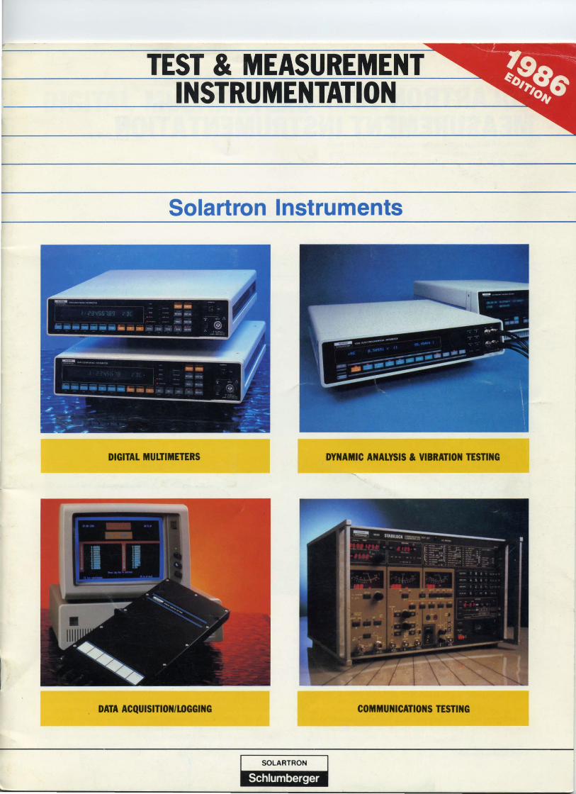
TEST & MEASUREMENT INSTRUMENTATION
Solartron Instruments
DIGITAL MULTIMETERS DYNAMIC ANALYSIS & VIBRATION TESTING
. DATA ACQUISITION/LDGGING COMMUNICATIONS TESTING
I SOLARTRON I . . __________________________________ ~_~ __ N_l'_i,_,j._I§_A_·t_§ .. __ ~ _______________________________ J

SOLARTRON TEST & MEASUREMENT INSTRUMENTATION . •• Innovative design and sound engineering are the keys to an advanced technology for today's most demanding applications.
© 1986, Solartron Instruments
DIGITAL MULTIMETERS Pages 3-6 Since introducing the world's first digital voltmeter nearly 30 years ago, Solartron has fol· lowed a continuous development program to maintain its position of leadership. Today we offer a comprehensive range of instruments fOl- production , laboratory, and ATE requirements-including the world's most accurate 8- Yo digit multimeter with unrivalled linearity and transfer accuracy.
DYNAMIC ANALYSIS AND VIBRATION TESTING Pages 9-12 Solartron has a long history of innovative instrumentation in the fields of control engineering, structural, vibration, and acoustic analysis, rotating mach i nery diagnosis, and electrochemistry. Our latest range of instruments all incorporate the powerful capabilities of microprocessors for ease of operation and extensive data reduction and analys is, as well as application orien ted software.
2
DATA ACQUISITION/LOGGING Pages 7, 8 Solartron produced the first data logger in 1952. From that experience comes the present Orion Series of data loggers that are the accepted industrystandards for research and industrial applications, as well as the new IBM® PC-based Model 3595 Isolated Measurement Pods (IMPs). Designed for onsite location in remote and harsh environments, or in the laboratory/R & D arena, each IMP can monitor up to 20 channels and up to 30 IMPs can be networked by an inexpensive 2-wire link_
'" A registered trademark of International Business Machines Corp.
COMMUNICATIONS TESTING Pages 13-15 Solartron's communications testers are designed for easy bench operation, but all can be computer controlled via the IEEE-488 interface bus for high vo lume ATE applications. Consisting of a high performance AM/FM/<I>M signal generator, all-in-one automated radio telephone test set, rf service monitor, and a cellular radio test system, these instruments combine outstanding performance with operator convenience_
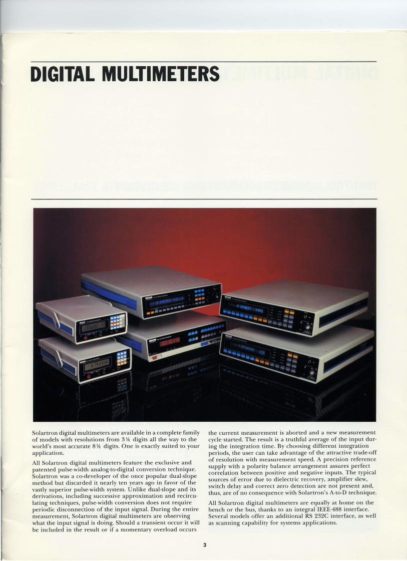
DIGITAL MULTIMETERS
Solartron digital multimeters are available in a complete family of models with resolutions from 3 Yo digits all the way to the world's most accurate 8 Yo digits. One is exactly suited to your application.
All Solartron digital multi meters feature the exclusive and patented pulse·width analog·to·digital conversion technique. Solartron was a co· developer of the once popular dual·slope method but discarded it nearly ten years ago in favor of the vastly superior pulse·width system. Unlike dual·slope and its derivations, including successive approximation and recircu· lating techniques, pulse·width conversion does not require periodic disconnection of the input signal. During the entire measurement, Solartron digital multi meters are observing what the input signal is doing. Should a transient occur it will be included in the result or if a momentary overload occurs
3
the current measurement is aborted and a new measurement cycle started. The result is a truthful average of the input duro ing the integration time. By choosing different integration periods, the user can take advantage of the attractive trade·off of resolution with measurement speed. A precision reference supply with a polarity balance arrangement assures perfect correlation between positive and negative inputs. The typical sources of error due to dielectric recovery, amplifier slew, switch delay and correct zero detection are not present and, thus, are of no consequence with Solartron's A-to·D technique.
All Solartron digital multimeters are equally at home on the bench or the bus, thanks to an integral IEE£.488 interface. Several models offer an additional RS 232C interface, as well as scanning capability for systems applications.

DIGITAL MULTI METERS
7081/7071 .. . HIGHEST ACCURACY AND RESOWTION
Both instruments provide identical facilities for measurement, data processing and storage, and remote control. The 8 Yo digit 7081 is the world's most accurate digital multimeter, with unsurpassed resolution , linearity, and transfer accuracy. It pro· vides Standards Room Integrity for everyday measurements. The 7 Yo digit 7071 is the ideal choice for ATE applications with demanding requirements.
A comprehensive package of processing programs includes: multiply, linear scaling and offset; maximum, minimum, and pe·ak·to·peak; high and low limits with alarm output; statistics for mean, variance, standard deviation, and rms; and ratio. Digital filtering provides a continuous average, average of n results, or a walking window average of the most recent n reo suits. Up to 1500 readings can be stored in a fail-safe history file for later printout or processing. See page 6 for specifications.
4
7060 . .. CUSTOM CONFIGURED MULTIMETER Here is a high performance 6- Yo instrument that can be configured to meet exact test function requirements. Four versions provide:
• de voltmeter • dc/ac (rms) voltmeter plus ratio • full multimeter (ac mean) plus ratio • full multimeter (ac rms) plus ratio
See page 6 for specifications.
7010 . .. COST EFFECTIVE, HIGH SPEED IS-CHANNEL SCANNER The 7010 provides 16-channel scanning at a switching rate of 130 channels per second. Designed to work with the models 7081 , 7071, and 7060, and capable of being "daisy-chained" for up to 256 channels, the 7010 can communicate with a controller via an RS 232C link or on the IEEE-488 bus.

DIGITAL MULTI METERS
7061 ... FAST ATE MULTIMETER WITH SCANNING CAPABILITY
When speed is critical, the 7061 is the choice. Capable of cap· turing up to 1500 readings per second into an internal memory of up to 8000 readings, providing an output of 300 readings per second on the IEEE-bus, responding within 3 milliseconds of an external trigger and signaling an alarm condition within 1 millisecond, the 7061 is both fast and accurate. Using a cap· ture feature, results may be tracked until a defined input level is detected. Tracking continues until a specified number of results have been collected. Memory then contains a record of results , before and after the desired event. An extensive math and statistics package can then produce results in ex· actly the format required. A ratio function allows for the comparison of any measurement to any other measurement.
A built·in scanner option houses 16 channels in addition to the main and reference inputs. All 18 channels may be scanned in any sequence at a rate of 300 channels per second. Each of the channels can be set for any measurement function, delay and scale length, as well as math programs. If the scanner is not fitted, the 16 channels are recognized as "virtual chan· nels" . This gives access to various combinations of programs, allowing a single input to be manipulated in various ways. See page 6 for specifications.
5
7151/7150 . .. HIGH PERFORMANCE AT MODERATE COST These two multi meters both offer performance and operating convenience far in excess of their moderate cost. The 7150 and 7151 are both fu ll function multimeters with up to 6· Yo d igits resolution and simi lar specifications. The 7151 adds the abi lity to make accurate temperature measurements, as well as a stored history file of 500 readings and a powerfu l math and statistics package which can be preprogrammed for data processing and reduction . The 7151 also provides an oscillo· scope output for viewing the last 100 readings for trend an· alysis and a zoom feature wh ich allows for detai led ana lysis of a portion of that trend.
. See page 6 for specifications.

DIGITAL MULTI METERS
SPECIFICATIONS (accuracy in % reading + digits)
Parameter 7081 (8 Y, digits) 7071 (7 y, digits) 7061 (7 y, digits) 7060 (6 Y, digits) 7151 (5 Y, digits) 7150 (5 Y, digits)
Volts, de Range 10 nV-1000 V 10 nV-1000 V 100 nV-1000 V 1 /LV-1000 V 100 nV-1000 V 1 /LV-1000 V Accuracy 0_00012 + 4 0_0003 + 10 0_0005 + 2 0_002 + 6 0_002 + 3 0_002 + 5
Volts, rms ae Range 1 /LV-750 V 1 /LV-750 V 1 /LV-750 V 1 /LV-750 V 1 /LV-750 V 10 /LV-750 V Frequency dc-l MHz dc-l MHz 10 Hz-500 kHz 40 Hz-50 kHz 10 Hz-500 kHz 10 Hz-300 kHz
(7060E) 10 Hz-IOO kHz (7060G)
FS Crest Factor 5 5 10 4 (7060E) 10 7 5 (7060G)
Accuracy 0_005 + 50 0_005 + 50 0_05 + 20 0_03 + 20 0_05 + 20 0_1 + 70 (7060E) 0_05 + 50 (7060G)
Volts, mean ac Range 1 /LV-750 V Frequency -- -- -- 40 Hz-50 kHz -- --
Accuracy 0_03 + 20 (7060C)
Current, de Range -- -- I/LA -2A 1 nA-IA 10/LA-2A 10/LA-2A
Accuracy 0_02 + 10 0_04 + 10 0_02 + 3 0_02 + 5 (7060C/G)
Current, ae Range 10/LA-2A 1 nA-IA 10/LA-2A 10/LA-2A
Frequency -- -- 40-440 Hz 40 Hz-5 kHz 40-440 Hz 40 Hz-5 kHz Accuracy 0_05 + 20 0_08 + 40 0_05 + 20 0_1 + 100
(7060C/G)
Ohms Range 10 /Ln-1000 Mn 10 /Ln-1000 Mn 100 /Ln-1000 Mn 1 mn-l00 Mn 10 mn-20 Mn 100 mn-20 Mn Accuracy 0_00015 + 4 0_0003 + 10 0_0007 + 3 0_002 + 6 0_003 + 3 0_004 + 5
Temperature Range -- -- - 200 to + 600 DC -- - 200 to + 600 DC --Resolution 0_001 DC, F, or K 0_01 DC, F, or K
6

DATA ACQUISITION/LOGGING
3530 ORION SERIES ... MULTI·TASKING AND INTELLIGENT
The Orion Series is ideally suited for structural analysis, agricultural research, battery, engine and materials testing, temperature and strain measurements in the aerospace and transportation industries, environmental disturbance testing, turbine alarm monitoring, and process control monitoring in the food, chemical, beverage, and printing industries_ Both the 3530A and 3530 Delta feature 200 channel capability in one box (400 or 600 channels with slave scanners), up to 500 channels per second switching speed with full normal mode rejection of ac interference at sampling rates of 40 channels per second, up to 8 independent and prioritized tasks (separate or interrelated), powerful math and statistic programs for data reduction, digital and analog outputs for alarm and control functions, magnetic storage of data and operating programs, and a built-in alphanumeric printer. Both a real time clock arid memory are battery maintained for power fail protection and recovery_ Although all input and output modules are compatible with both the 3530A and the 3530 Delta, it is the computing power built into the 3530 Delta which is the basic difference between the two units_ Using a Basic-like language, simple inter-channel calcu lations or sophisticated data reduction and output control can be easily implemented_
7
Both instruments accept inputs from voltage and current sources (dc and ac), thermocouples and RTDs, strain gages in ~, Yo, or fu ll configurations, magnetic and optical sensors, status and events, and time periods and frequency_ Input conditioning is software controlled, allowing inputs to be freely mixed or altered to fit a new application_
SPECIFICATIONS, 3530A AND 3530D Analog inputs Switching DC voltage AC voltage Current Resistance Thermocouples RTD Strain gages
Digital inputs Frequency Period and interval Totalize Status Events
Outputs Analog Digital
Interfaces Standard Optional
Option 3530B/F
Reed relay or solid-state I /LV-lOO V I /LV-20 V DC or AC 2 or 4-wire E, j , K, R, S, and T 100 (} 4-wire ~, Yo, or full-bridge
Up to 400 kHz 500 /Ls-60 min_ Up to 32 bits (> 4 x 10") Single bits or BCD Single, counted, or totalized
0-10 V, or 4-20 rnA Switched outputs for HI or LO alarm at any channel input
RS 232C RS 422 or IEEE-488
Blank panel version of 3530AID for computer control; no magnetic storage or printer.

DATA ACQUISITION/LOGGING
3595 .. . ISOLATED MEASUREMENT PODS (IMPs) FOR IBM PC
Solartron IMPs under IBM "'PC control are ideal for data acquisition and logging in harsh industrial environments. Housed in a sealed NEMA 4X enclosure, and with an operating temper· ature range from - 20°C to + 70°C, an IMP can be mounted directly at the point of measurement and provide up to 20 channels of high precision analog or digital data acquisition. Up to 30 IMPs can be computer controlled over a simple 2·wire S-Net serial link with a data transmission speed of 163,000 bits per second. All IMPs derive their power from the same S·Net link.
IMP Type 35951A 35951B Analog Analog
Function: Thermocou pies, Strain gages, voltage, current RTDs, voltage,
resistance
Channels: 20 10
Switching: 3-pole FET 6·pole FET
V ohage, dc: 1 /-tV· 1 2 V 1 /-tV·2 V
Current, dc: Shunt dependent, N/A 10 nA·20 rnA nom.
Resistance: N/A 2 mD·2.5 kD
. Temperature: Thermocouple EJ,K,T,R,S RTD 100 D 4-wire
Strain: N/A ~, Yo, and full bridge
IMPs operate in a polled environment which insures that up to 600 channels can be triggered, measured and the results reo turned to the host computer in 1 second.
Each IMP is transformer coupled to S-Net for 500 V isolation and high power line noise immunity. On·board intelligence performs automatic drift corrections and provides fu ll signal conditioning for strain gages, RTDs, thermocouples, dc vol· tage and current, and resistance, with results converted to engineering units before transmission.
I- SCATTERED LOCATIONS
35951C Analog
IBM ® PC WITH ADAPATOR CARD
Thermocou pies, voltage, current
20
3·pole reed
1 /-tV·12 V; 10 /-tV-100 V, optional
Shunt dependent, 10 nA·20 rnA nom.
N/A
EJ,K,T,R,S
N/A
8
UP TO 1 Km THERMOCOUPLES. STRAIN GAGES. VOLTAGE. CURRENT RTDS. RESISTANCE
THERMOCOUPLES. DIGITAL VOLTAGE ,CURRENT INPUT/OUTPUT
IMP Type 35952A Digital
Function: Digital Inputl Output
Channels: 20
Status (0 and 1): 0.8 and 2.0 V, or 3.0 and 9 V
Frequency: Maximum 49 kHz Gate times 0.01,0.1, ] ,and lOs
Period: Range ],]0,100, and 1000 Resolution 10 /-ts
Events, resolution: 10 ms
Counts: 24 bits (> 16 x ]06)
Output: Type FET, closes for
Withstand logic 1 60 V, max.
Sink ]00 rnA, max.
DYNAMIC ANALYSIS & VIBRATION TESTING
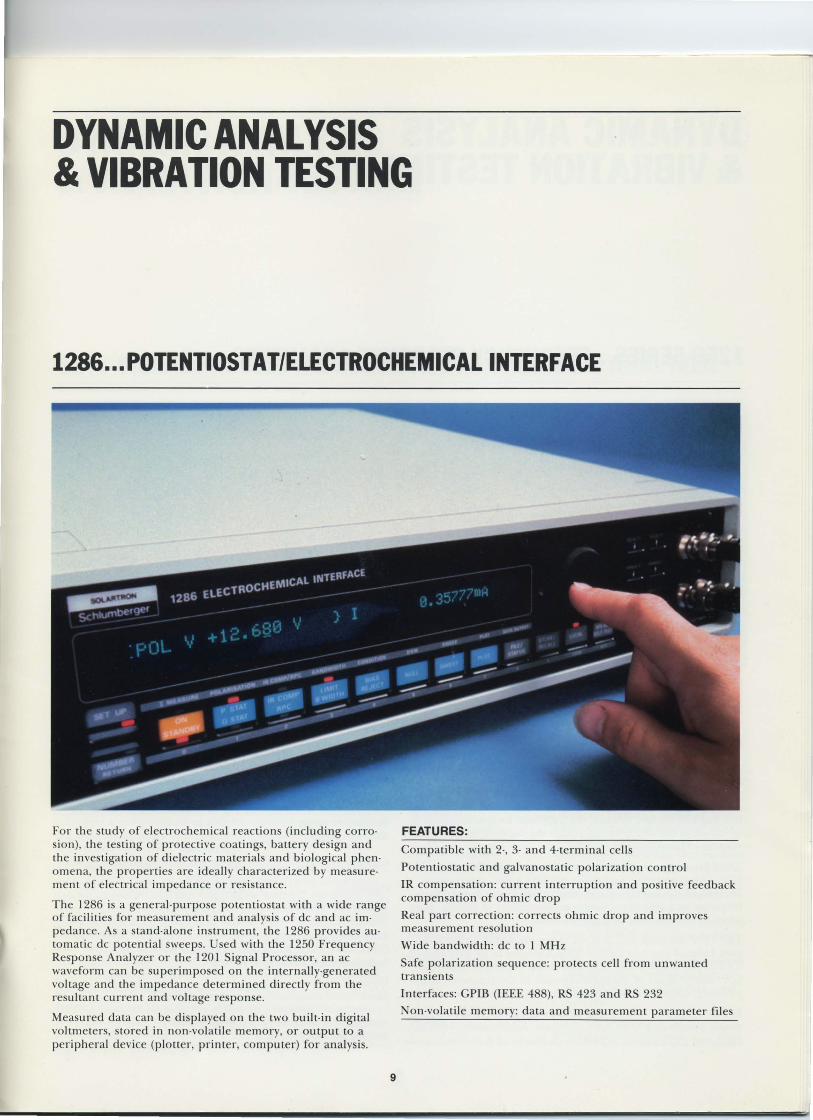
1286 ... POTENTIOSTAT/ELECTROCHEMICAL INTERFACE
For the study of electrochemical reactions (induding corrosion), the testing of protective coatings, battery design and the investigation of dielectric materials and biological phenomena, the properties are ideally characterized by measurement of electrical impedance or resistance_
The 1286 is a general-purpose potentiostat with a wide range of facilities for measurement and analysis of dc and ac impedance_ As a stand-alone instrument, the 1286 provides automatic dc potential sweeps_ Used with the 1250 Frequency Response Analyzer or the 1201 Signal Processor, an ac waveform can be superimposed on the internally-generated voltage and the impedance determined directly from the resultant current and voltage response.
Measured data can be d isplayed on the two built- in digital voltmeters, stored in non-volatile memory, or output to a peripheral device (plotter, printer, computer) for analysis.
9
FEATURES:
Compatible with 2-, 3- and 4-terminal cell s
Potentiostatic and galvanostatic polarization control
IR compensation: current interruption and positive feedback compensation of ohmic drop
Real part correction: corrects ohmic drop and improves measurement resolution
Wide bandwidth: dc to 1 MHz
Safe polarization sequence: protects cell from unwanted transients
Interfaces: CPIB (IEEE 488), RS 423 and RS 232
Non-volatile memory: data and measurement parameter files

DYNAMIC ANALYSIS & VIBRATION TESTING
1250 SERIES ... FREQUENCY RESPONSE ANALYZERS
The 1250 series Frequency Response Analyzers use the single sine correlation analysis technique to provide fast and precise measurement of the amplitude and phase characteristics of the device under test. The device can be stimulated with a sine, square or triangular waveform from the built-in generator. For self-excited devices, the 1250 can be synchronized to an external reference to determine the harmonically related response characteristics_
The 1250 covers a wide frequency range, from 10 /LHz to 65 kHz_ The correlation technique enables either rejection or analysis of the harmonic components of a non-linear system response and also the accurate measurement of signals, even when heavily contaminated with noise_
The 1250 contains two analysis channels, enabling the complex ratio of an y two signals from a system to be determined_ This is particularly suited to derivation of simple input/output relationships or the measurement of electrochemical impedance, when used in conjunction with the 1286 Potentiostat.
For multi-output systems the 1254 Analyzer provides simultaneous measurement on four channels_ Additionally, both the 1250 and 1254 can be expanded in blocks of 8 channels to an
10
additional 32 parallel channels using 1251 Slave Analyzers_ Multichannel operation is ideal for modal analysis of structures and condition monitoring of rotating machinery_
FEATURES:
Frequency range Channels, 1250
Channels, 1254
Generator Generator output Measurement
1251 Slave Analyzers
10 /LHz to 65 kHz Simultaneous measurement on 2
channels Simultaneous measurement on 4
channels Triangle, square, sine 10 mV to 10 V 1 /LV to 300 V
Channels for simultaneous measurement: 1 to 32 Interface: Independent IEEE 488
Options ModulatorlDemodulator for carrier systems Synchronizer system Auxiliary generators (0°, + 90°, + 180°) Analog plotter interface

DYNAMIC ANALYSIS & VIBRATION TESTING
1201 SIGNAL PROCESSOR ••• MORE THAN A SPECTRUM ANALYZER
The 1201 is a 500 line dual-channel spectrum analyzer with a bandwidth of 30 kHz and resolution down to 2 mHz_ A wide range of single and dual channel functions is available, including auto- and cross-power spectra, synchronous spectrum, transfer function and coherence in the frequency domain and auto- and cross-correlation, time record and impulse response in the time domain_ A second Fourier transform, of the auto power spectrum, a lso provides the power cepstrum for the study of periodicities in the frequency domain_ Baseband, zoom and octave measurements are provided, while a unique true logarithmic analysis mode optimizes the resolution, particularly at low frequencies, when analysis is required over wide bandwidths_
The 1201 features a 3 Yo" dual-sided floppy disk for storage and recall of instrument setups and data_ Up to 650 Kbytes can be stored in a format compatible with HP computer systems_ An application software package is available for modal analysis, including SDOF and MDOF curve fitting, animated mode shapes, structural modification and response prediction_ Another acoustic intensity package provides 3-D measurements; contour, vector, and 3-D animated displays, and phase/magnitude correction_ A rotating mach inery software package all ows balancing and trend analysis_
Display features include the ability to present split screen waterfall records, as well as the usual Bode and Nyquist formats_ Hard copies of the displays can be obtained using analog or digital plotters, or a video hard copier. The video
11
output can also be used to reproduce the display on a remote monitor.
Where external stimulation of the system under investigation is required, an integral generator provides pseudo-random noise, periodic multi-sine and impulse excitation_
FEATURES: Frequency range Spectral lines Windows Averaging modes
Single channel functions
Dual channel functions
Computed functions
Display formats
Option
DC to 30 kHz 500 Uniform, Hanning, and Flat Top RMS, exponential, time and peak
hold Auto-power spectrum, synchronous
spectrum, auto-correlation, time record and power cepstrum
Cross-power spectrum, transfer function, coherence, crosscorrelation and impulse response
Power in band, equivalent noise bandwidth
Linear, logarithmic, power spectral density, phase, real and imaginary,
yquist, octave, 1/3 octave, and waterfall
IEEE 488 interface Analog plotter interface

DYNAMIC ANALYSIS " VIBRATION TESTING
1209/1210 ... RANDOM VIBRATION CONTROLLER
Two Random Vibration Controllers provide all the facilities necessary to achieve adaptive loop control, or equalization, of a random excitation signal to match a user·defined de· mand spectrum. The 1210, with a frequency range of 6 Hz to 3 kHz, is ideal for military and aerospace applications in accordance with MIL·STD 781C(D), 810C(D), and NAVMAT P-9492. The 1209, with a frequency range of 1 Hz to 500 Hz, is des igned for packaging and vehicular environmental test· ing and conforms to ASTM packaging test procedures.
Botb instruments allow up to 8 tests to be programmed and stored from the front panel for easy recalL Each test includes automated cal ibration results , demand test spectrum, level sequence data, and alarm/abort requirements.
12
Full system interlocking and alarm limits are incorporated to insure a safe test. During the vibration test the instruments continuously mon itor the incoming signals for failure due to breakages and for high ampli tude spectral components that exceed programmable abort and alarm spectral limits. If these li mits are exceeded, the Model 1209 or 1210 can be made to produce an audible signal or, in the case of a break· age being detected, to shut down the system in a controlled manner.
The 120911210 can also be used in an open loop mode, as a real time FFT spectrum analyzer, for estimating system trans· fer function or for general signal analysis.
Both instruments feature a large 9 inch CRT display giving clear, high resolution pictures. The display is used to moni· tor time and frequency spectrums of the test data. Fully an· notated, the display provides accurate information about the spectral data and visual checks on the progress of the equali· zation process.
A video output is provided, as standard, for driving video hard·copying devices or large screen TV sets. Options are avai lable to copy the results onto analog or digital type plot· ters. An optional IEEE 488 interface provides for full remote controL
FEATURES:
Frequency range Resolution, 500 lines Dynamic range,
1209 1·500 Hz
1 Hz
1210 6 Hz·3 kHz
6 Hz
power spectrum density > 65 dB >65 dB Accelerometer inputs Charge or voltage Generator output Psuedo·random binary sequence
Demand profile
Protection faci li ties
Option
(PRBS) with gaussian amplitude probability density function
Up to 99 breakpointsllevels in 8 profiles
Abort and alarm limits, "graceful" power up and down, external interlocks, front panel keyswitch
IEEE 488 interface Analog plotter interface
COMMUNICATIONS TESTING
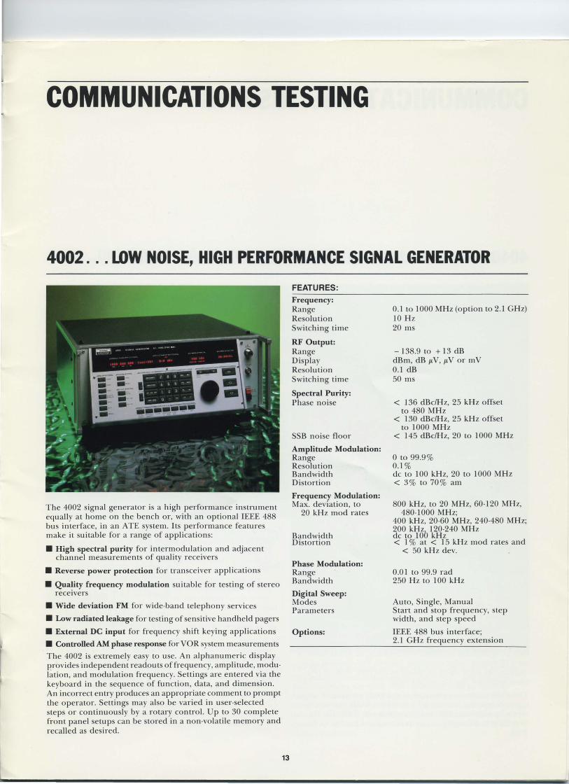
4002 ... LOW NOISE, HIGH PERFORMANCE SIGNAL GENERATOR
The 4002 signal generator is a high performance instrument equally at home on the bench or, with an optional IEEE 488 bus interface, in an ATE system. Its performance features make it suitable for a range of applications:
• High spectral purity for intermodulation and adjacent channel measurements of quality receivers
• Reverse power protection for transceiver appli cations
• Quality frequency modulation su itable for testing of stereo receivers
• Wide deviation FM for wide·band telephony services
• Low radiated leakage for testing of sensitive handheld pagers
• External DC input for frequency shift keying applications
• Controlled AM phase response for VOR system measurements
The 4002 is extremely easy to use. An alphanumeric display provides independent readouts offrequency, amplitude, modu· lat ion, and modulation frequency. Settings are entered via the keyboard in the sequence of function, data, and dimension. An incorrect entry produces an appropriate comment to prompt the operator. Settings may also be varied in user·selected steps or continuously by a rotary control. Up to 30 complete front panel setups can be stored in a non·volatile memory and recalled as de ired.
13
FEATURES:
Frequency: Range Resolution Switching time
RF Output: Range Display Resolution Switching time
Spectral Purity: Phase noise
SSB noise floor
Amplitude Modulation: Range Resolution Bandwidth Distortion
Frequency Modulation: Max. deviation, to
20 kHz mod rates
Bandwidth Distortion
Phase Modulation: Range Bandwidth
Digital Sweep: Modes Parameters
Options:
0.1 to 1000 MHz (option to 2.1 GHz) 10 Hz 20 ms
-138.9 to + 13 dB dBm, dB jJ.V, jJ.V or mV 0.1 dB 50 ms
< 136 dBC/Hz, 25 kHz offset to 480 MHz
< 130 dBC/Hz, 25 kHz offset to 1000 MHz
< 145 dBC/Hz, 20 to 1000 MHz
o to 99.9% 0.1% dc to 100 kHz, 20 to 1000 MHz < 3% to 70% am
800 kHz, to 20 MHz, 60·120 MHz, 480·1000 MHz;
400 kHz, 20·60 MHz, 240·480 MHz; 200 kHz
b 120·240 MHz
dc to 10 kHz < 1 % at < 15 kHz mod rates and
< 50 kHz dev.
0.01 to 99.9 rad 250 Hz to 100 kH z
Auto, Single, Manual Start and stop frequency, step width, and step speed
IEEE 488 bus interface; 2.1 GHz frequency extension

COMMUNICATIONS TESTING
4040/4039 ... TRANSCEIVER TEST IN LESS THAN 2 MINUTES
The 4040 Communications Test Set is the first compact in· strument that can completely characterize a transceiver in less than 2 minutes, including adjacent channel selectivity to CCITT and MPTIDTI regulations. Equally useful for produc· tion testing and quality assurance, as well as field diagnosis and servicing, the 4040 can serve as a manual test set, as an automatic test station using a unique learning mode or its own programming keyboard and memory, or as the heart of an ATE system under computer control. The optional mini· cassette can store up to 18 different test files, with 50 pro· gram steps per file, for instant recall.
T.h~ 4039 is a low cost v~rsion of t~e 4040, identical in capa· bllIty, except that there IS no provision for AM measure· ments or wideband FM, and phase noise is < 122 dBC/Hz with 25 kHz offset. Mini·cassette storage is optional in the 4039.
14
FEATURES:
Receiver Measurements Carrier range RF output Phase noise, 25 kHz
offset Frequency modulation Amplitude modulation Phase modulation
0.4-960 MHz 0.1 p.V -2V < -132 dBC/Hz (4040) < - 122 dBC/Hz (4039) 0-20 kHz 0-90% (4040 only) 0-6 rad
Transmitter Measurements Carrier range 30 kHz - 960 MHz Input level 10 p.W-50 W Frequency modulation 0 - 50 kHz (2 - 960 MHz) Amplitude modulation 0-99% (4040 only) Phase modulation 0 - 6 rad (2 - 960 MHz)
Additional Features SINAD meter Distortion meter AF voltmeter DC voltmeter DC ammeter
Options IEEE 488 bus interface
Cassette recorder Adjacent channel
power meter
Duplex meter
Control interfaces
Stabitexter
Rack mounting kit
Transport case
1-46 dB 0.1-99% 0.2 mV -30 V 0-50 V 0-15 A
For external printer and connection to controller/4922 For storage of test sequences For all selective RF levels
including harmonics and spuri.ous signals
For repeater measurements and full·duplex operation (4922)
32·relay unit to control peripheral devices or UUT and to set radio channels with BCD code. 5·relay unit to control RxlTx, squelch on/off, upper/lower band and coder/decoder of tone sequences
Write and store free·form comments
19 " conversion kit to rack mounting
Carrying case with shock absorption

COMMUNICATIONS TESTING
4922 ... UNIVERSAL RADIO CODE ANALYZER (WITH CELWLAR CAPABILITY)
The Model 4922 provides simultaneous signal generation and analysis of selective call and coded data messages, including the complete test of cellular radio systems. Cellular test rou· tines include AMPS (U.S.), TACS (Britain), NMT (Scandina· via), NMT (Austria), and C-net (Germany). All parameters, such as tone frequencies, SAT tones, and baud rates, are menu·driven. Other routines can be fully duplex·simulated and the user has aq:ess to different simulation levels from the simple·to·enter subscriber numbers and reduced bit·level manipulation of each individual bit. Results are available in either hexidecimal or binary format on a CRT display or op· tional printer.
In addition to cellular systems, the 4922 can test sequential call tone systems , with built-in tone sequences, for ZVEI 1, ZVEI 2, CCIR, CCITT, EEA, EIA, VDEM, EURO, NATEL, and up to 5 user-specified call series. Up to 28 sequential tones can be set with specified frequencies, tone amplitudes and durations, and time pauses between tones. Each tone can be combined with a simultaneous second tone, audible or subaudible. Pager systems may also be addressed and analyzed, including POCSAG, Motorola Golay, and NEC binary formats .
15
The 4922 can be used with any existing full duplex service monitor to form a complete RF test system. The Solartron 4062 integrates the 4922 with either the 4040 or 4039 RF Service Monitor to provide a completely automatic and universal test set capable of RF and data stream message testing down to bit level. The 4062 provides unparall('led testing capability of land mobile, 2-way radios, pagers, and cellular radio telephones.
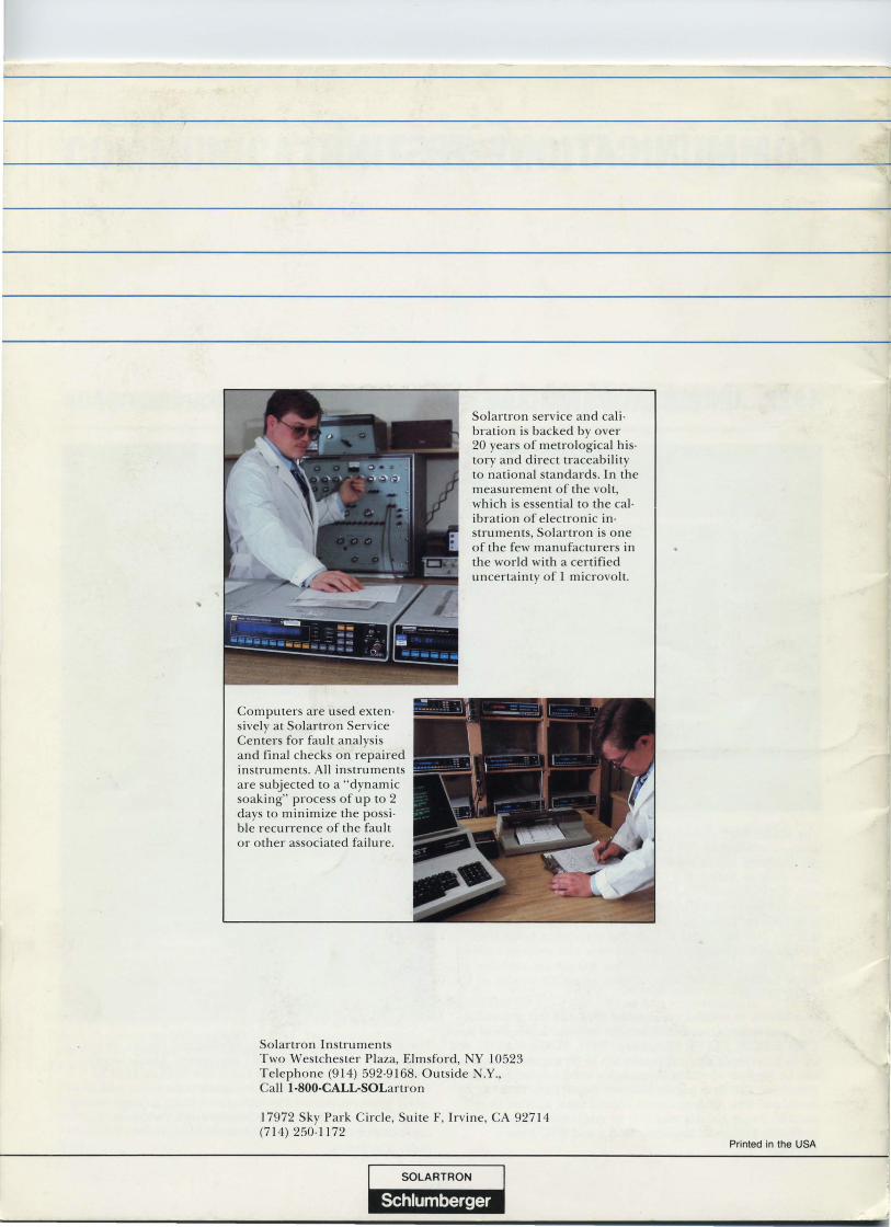
Computers are used exten· sively at Solartron Service Centers for fault analysis and final checks on repaired instruments. All instruments are subjected to a "dynamic soaking" process of up to 2 days to minimize the possi· ble recurrence of the fau lt or other associated failure.
Solartron Instruments
Solartron service and cali· bration is backed by over 20 years of metrological his· tory and direct traceability to national standards. In the measurement of the volt, which is essential to the cal· ibration of electronic in· struments, Solartron is one of the few manufacturers in the world with a certified uncertainty of 1 microvolt.
Two Westchester Plaza, Elmsford, Y 10523 Te lephone (914) 592·9168. Outside N.Y., Call 1·800·CALL·SOLartron
17972 Sky Park Circle, Suite F, Irvine, CA 92714 (714) 250-1172
I.: SOlARTRON ~
1m'jlll ·MAW
Printed in the USA