Embed Size (px)
Citation preview

Test Equipment Solutions Datasheet
Test Equipment Solutions Ltd specialise in the second user sale, rental and distribution of quality test & measurement (T&M) equipment. We stock all major equipment types such as spectrum analyzers, signal generators, oscilloscopes, power meters, logic analysers etc from all the major suppliers such as Agilent, Tektronix, Anritsu and Rohde & Schwarz.
We are focused at the professional end of the marketplace, primarily working with customers for whom high performance, quality and service are key, whilst realising the cost savings that second user equipment offers. As such, we fully test & refurbish equipment in our in-house, traceable Lab. Items are supplied with manuals, accessories and typically a full no-quibble 2 year warranty. Our staff have extensive backgrounds in T&M, totalling over 150 years of combined experience, which enables us to deliver industry-leading service and support. We endeavour to be customer focused in every way right down to the detail, such as offering free delivery on sales, covering the cost of warranty returns BOTH ways (plus supplying a loan unit, if available) and supplying a free business tool with every order.
As well as the headline benefit of cost saving, second user offers shorter lead times, higher reliability and multivendor solutions. Rental, of course, is ideal for shorter term needs and offers fast delivery, flexibility, try-before-you-buy, zero capital expenditure, lower risk and off balance sheet accounting. Both second user and rental improve the key business measure of Return On Capital Employed.
We are based near Heathrow Airport in the UK from where we supply test equipment worldwide. Our facility incorporates Sales, Support, Admin, Logistics and our own in-house Lab.
All products supplied by Test Equipment Solutions include:
- No-quibble parts & labour warranty (we provide transport for UK mainland addresses).- Free loan equipment during warranty repair, if available.- Full electrical, mechanical and safety refurbishment in our in-house Lab.- Certificate of Conformance (calibration available on request).- Manuals and accessories required for normal operation.- Free insured delivery to your UK mainland address (sales).- Support from our team of seasoned Test & Measurement engineers.- ISO9001 quality assurance.
Test equipment Solutions LtdUnit 8 Elder WayWaterside DriveLangleyBerkshireSL3 6EP
T: +44 (0)1753 596000F: +44 (0)1753 596001
Email: [email protected]: www.TestEquipmentHQ.com
Agilent PSA Series Spectrum Analyzers
Data Sheet
40/80 MHz
Analysis Bandwidth
Now Available On
50 GHz PSA!
The Agilent PSA Series offers high-
performance spectrum analysis, up
to 50 GHz, with powerful one-button
measurements, a versatile feature
set, and a leading-edge combination
of flexibility, speed, accuracy, analysis
bandwidth, and dynamic range. From
millimeter wave and phase noise
measurements to spur searches and
modulation analysis, the PSA Series
offers unique and comprehensive
high-performance solutions to R&D
and manufacturing engineers in
cellular and emerging wireless
communications, aerospace,
and defense.
For more information regarding the PSA wide analysis bandwidth, see the 40/80 MHz BW digitizers, Option 140/122, technical overview at www.agilent.com/find/psa
Models
E4443A 3 Hz to 6.7 GHz
E4445A 3 Hz to 13.2 GHz
E4440A 3 Hz to 26.5 GHz*
E4447A 3 Hz to 42.98 GHz
E4446A 3 Hz to 44 GHz*
E4448A 3 Hz to 50 GHz*
* 325 GHz with external mixing
2
Definitions and Conditions ............3
Frequency Specifications ..............4
Frequency range ..................................4
Frequency reference ...........................4
Frequency readout accuracy .............4
Marker frequency counter .................4
Frequency span ...................................4
Sweep time and triggering ................5
Sweep (trace) point range .................5
Gated sweep ........................................5
Gated FFT ..............................................5
Resolution bandwidth (RBW) ...........5
Analysis bandwidth ............................6
Video bandwidth (VBW) ....................6
Stability .................................................6
Amplitude Specifications .............. 7
Amplitude range ..................................7
Maximum safe input level .................7
1dB gain compression (two tone) ....7
Typical gain compression (two tone) ...7
Displayed average noise level (DANL) ...8
Display range .................................... 10
Frequency response ......................... 10
Input attenuation switching
uncertainty ........................................ 10
Total absolute amplitude accuracy 10
Input voltage standing wave ratio
(VSWR) .............................................. 11
Resolution bandwidth switching
uncertainty ........................................ 11
Reference level ................................. 11
Display scale switching uncertainty .....11
Display scale fidelity ........................ 11
Spurious response ........................... 11
Second harmonic distortion (SHI) ...12
Third-order intermodulation
distortion (TOI) .................................. 12
Residual responses .......................... 14
Trace detectors ................................. 14
EMI detectors ................................... 14
Option E444xA-1DS, preamplifier ....14
Option E444xA-110, preamplifier ... 14
Measurement speed ........................ 14
Option AYZ, external mixing ........... 15
Option 123, preselector bypass ...... 15
Power Suite Measurement
Specifications . . . . . . . . . . . . . . . 16
Channel power . . . . . . . . . . . . . . . . 16
Occupied bandwidth . . . . . . . . . . . 16
Adjacent channel power . . . . . . . . 16
Multi-carrier power and ACP . . . . 16
Power statistics CCDF . . . . . . . . . . 16
Harmonic distortion . . . . . . . . . . . . 16
Intermod (TOI) . . . . . . . . . . . . . . . . 16
Burst power . . . . . . . . . . . . . . . . . . 16
Spurious emission . . . . . . . . . . . . . 17
Spectrum emission mask (SEM) . . 17
General Specifications . . . . . . . .18
Temperature range . . . . . . . . . . . . . 18
EMI compatibility . . . . . . . . . . . . . . 18
Audio noise . . . . . . . . . . . . . . . . . . 18
Military specification . . . . . . . . . . . 18
Power requirements . . . . . . . . . . . 18
Weight . . . . . . . . . . . . . . . . . . . . . . 18
Dimensions . . . . . . . . . . . . . . . . . . . 18
Warranty . . . . . . . . . . . . . . . . . . . . . 18
Calibration cycle . . . . . . . . . . . . . . . 18
Input and Outputs . . . . . . . . . . . .19
Front panel . . . . . . . . . . . . . . . . . . . 19
Rear panel . . . . . . . . . . . . . . . . . . . 20
PSA Series Ordering Information . . 21
PSA Series spectrum analyzer . . . 21
Options . . . . . . . . . . . . . . . . . . . . . . 21
Related Literature . . . . . . . . . . . .23
Support, Services, and Assistance . .24
Table of Contents
3
Definitions and Conditions
Specifications describe the performance
of parameters covered by the product
warranty and apply over 0 to 55 °C
unless otherwise noted. Typical
describes additional product performance
information that is not covered by the
product warranty. It is performance
beyond specifications that 80 percent
of the units exhibit with a 95 percent
confidence level over the temperature
range 20 to 30 °C. Typical performance
does not include measurement
uncertainty.
Nominal values indicate expected
performance, or describe product
performance that is useful in the
application of the product, but is not
covered by the product warranty.
The analyzer will meet its
specifications when:
• stored a minimum of two hours
within the operating temperature
range and turned on for at least
30 minutes with Auto Align On
selected.
• the instrument is within its one year
calibration cycle.
• Align All Now has been performed
within the past 24 hours or when
the temperature changes 3 °C.
• the instrument is under auto couple
control, except that Auto Sweep
Time = Accy.
• DC coupling applied if center
frequency is < 20 MHz.
This PSA Series data sheet is a
summary of the complete specifications
and conditions, which are available in
the PSA Series Spectrum Analyzers
Specification Guide.
The PSA Series Spectrum Analyzers
Specification Guide can be obtained
on the web through:
www.agilent.com/find/psa
Then follow this selection process:
• Select “Technical Support” under
Key Library Information
• Select “Manuals and Guides”
• Download specifications guide.
4
Frequency Specifications
Frequency range
E4443A (DC coupled) 3 Hz to 6.7 GHz (AC coupled) 20 MHz to 6.7 GHz
E4445A (DC coupled) 3 Hz to 13.2 GHz (AC coupled) 20 MHz to 13.2 GHz
E4440A (DC coupled) 3 Hz to 26.5 GHz1 (AC coupled) 20 MHz to 26.5 GHz1
E4447A (DC coupled) 3 Hz to 42.98 GHz
E4446A (DC coupled) 3 Hz to 44 GHz1
E4448A (DC coupled) 3 Hz to 50 GHz1
1 325 GHz with external mixers
Band Harmonic mixing mode (N)
0 1– 3 Hz to 3 GHz
1 1– 2.85 GHz to 6.6 GHz
2 2– 6.2 GHz to 13.2 GHz
3 4– 12.8 GHz to 19.2 GHz
4 4– 18.7 GHz to 26.8 GHz
5 4+ 26.4 GHz to 31.15 GHz
6 8– 31.0 GHz to 50.0 GHz
Frequency reference
Accuracy ±[(time since last adjustment x aging rate) + temperature stability + calibration accuracy]
Aging rate ± 1 x 10⁻⁷ / year
Temperature stability 20 °C to 30 °C ±1 x 10⁻⁸ 0 °C to 55 °C ±5 x 10⁻⁸
Achievable initial calibration accuracy ±7 x 10⁻⁸
Example frequency reference = ±(1 x 1 x 10–7 + 1 x 10⁻⁸ + 7 x 10⁻⁸)
accuracy 1 year after last adjustment = ±1.8 x 10⁻⁷
Frequency readout accuracy (start, stop, center, marker)
± (marker frequency x frequency reference accuracy + 0.25% x span + 5% x RBW + 2 Hz + 0.5 x horizontal resolution*)
* Horizontal resolution is span/(sweep points – 1)
Marker frequency counter
Accuracy ±(marker frequency x frequency reference accuracy + 0.100 Hz)
Delta counter accuracy ±(delta frequency x frequency reference accuracy + 0.141 Hz)
Counter resolution 0.001 Hz
Frequency span (FFT and swept mode)
Range 0 Hz (zero span), 10 Hz to maximum frequency of model
Resolution 2 Hz
Accuracy ±[0.2% x span + span / (sweep points – 1)]
5
Frequency Specifications (continued)
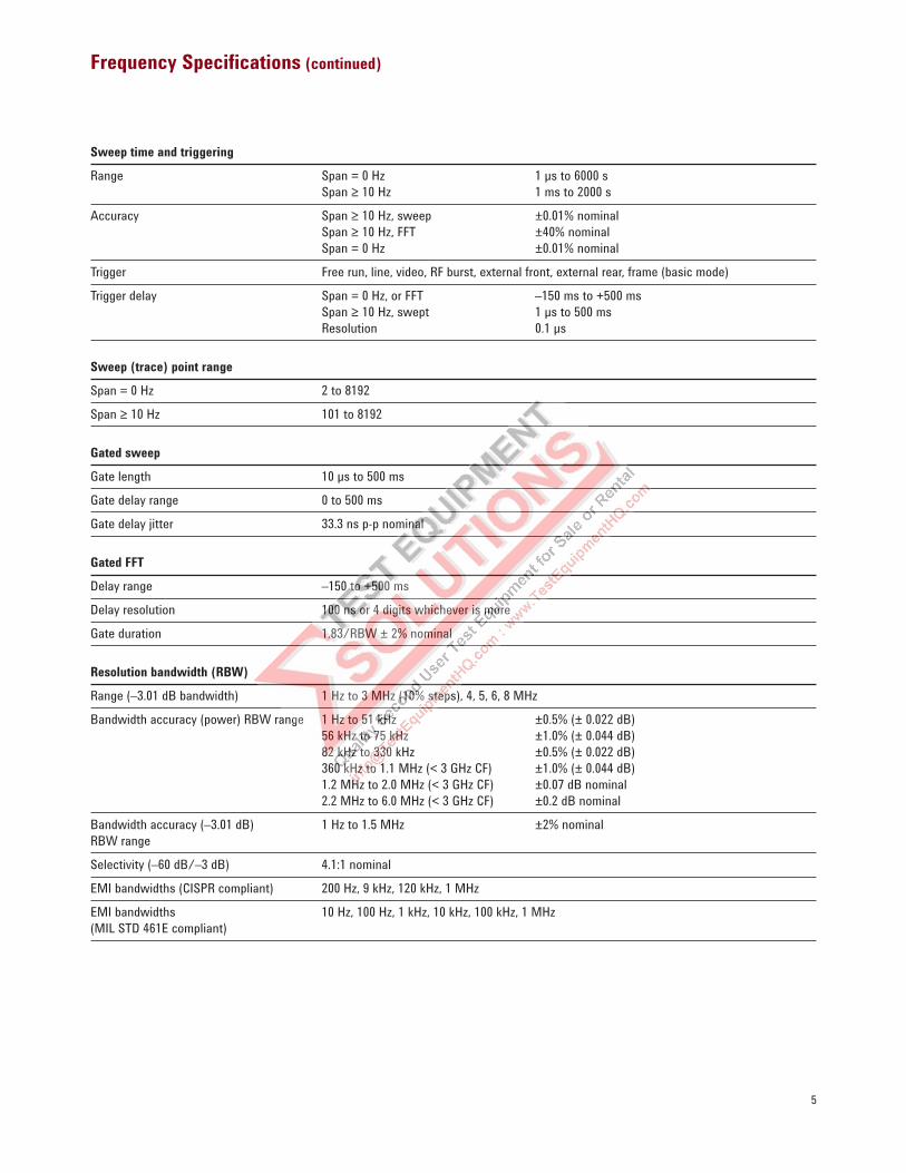
Sweep time and triggering
Range Span = 0 Hz 1 µs to 6000 s
Span ≥ 10 Hz 1 ms to 2000 s
Accuracy Span ≥ 10 Hz, sweep ±0.01% nominal
Span ≥ 10 Hz, FFT ±40% nominal
Span = 0 Hz ±0.01% nominal
Trigger Free run, line, video, RF burst, external front, external rear, frame (basic mode)
Trigger delay Span = 0 Hz, or FFT –150 ms to +500 ms
Span ≥ 10 Hz, swept 1 µs to 500 ms
Resolution 0.1 µs
Sweep (trace) point range
Span = 0 Hz 2 to 8192
Span ≥ 10 Hz 101 to 8192
Gated sweep
Gate length 10 µs to 500 ms
Gate delay range 0 to 500 ms
Gate delay jitter 33.3 ns p-p nominal
Gated FFT
Delay range –150 to +500 ms
Delay resolution 100 ns or 4 digits whichever is more
Gate duration 1.83/RBW ± 2% nominal
Resolution bandwidth (RBW)
Range (–3.01 dB bandwidth) 1 Hz to 3 MHz (10% steps), 4, 5, 6, 8 MHz
Bandwidth accuracy (power) RBW range 1 Hz to 51 kHz ±0.5% (± 0.022 dB)
56 kHz to 75 kHz ±1.0% (± 0.044 dB)
82 kHz to 330 kHz ±0.5% (± 0.022 dB)
360 kHz to 1.1 MHz (< 3 GHz CF) ±1.0% (± 0.044 dB)
1.2 MHz to 2.0 MHz (< 3 GHz CF) ±0.07 dB nominal
2.2 MHz to 6.0 MHz (< 3 GHz CF) ±0.2 dB nominal
Bandwidth accuracy (–3.01 dB) 1 Hz to 1.5 MHz ±2% nominal
RBW range
Selectivity (–60 dB/–3 dB) 4.1:1 nominal
EMI bandwidths (CISPR compliant) 200 Hz, 9 kHz, 120 kHz, 1 MHz
EMI bandwidths 10 Hz, 100 Hz, 1 kHz, 10 kHz, 100 kHz, 1 MHz
(MIL STD 461E compliant)
6
Frequency Specifications (continued)
Analysis bandwidth1
Maximum bandwidth
with Option 140 2 40 MHz
with Option 122 2 80 MHz
with Option B7J 10 MHz
321.4 MHz IF output 2 –1 dB bandwidth 20 to 30 MHz nominal Option 123 (> 2.85 GHz) 200 MHz nominal
–3 dB bandwidth 30 to 60 MHz nominal
70 MHz IF output2 (Option E444xA-H70) –1 dB bandwidth 20 to 30 MHz nominal
–3 dB bandwidth 30 to 60 MHz nominal
1 Analysis bandwidth is the instantaneous bandwidth available around a center frequency over which the input signal can be digitized for further analysis or processing in the
time, frequency, or modulation domain.
2 Not available for E4447A.
Video bandwidth (VBW)
Range 1 Hz to 3 MHz (10% steps), 4, 5, 6, 8 MHz and wide open
Accuracy ±6% nominal
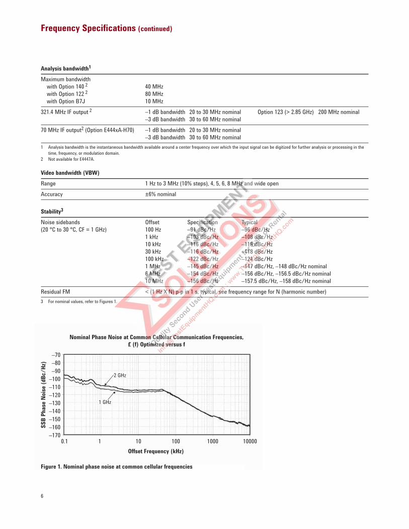
Stability3
Noise sidebands Offset Specification Typical
(20 °C to 30 °C, CF = 1 GHz) 100 Hz –91 dBc/Hz –96 dBc/Hz
1 kHz –103 dBc/Hz –108 dBc/Hz
10 kHz –116 dBc/Hz –118 dBc/Hz
30 kHz –116 dBc/Hz –118 dBc/Hz
100 kHz –122 dBc/Hz –124 dBc/Hz
1 MHz –145 dBc/Hz –147 dBc/Hz, –148 dBc/Hz nominal
6 MHz –154 dBc/Hz –156 dBc/Hz, –156.5 dBc/Hz nominal
10 MHz –156 dBc/Hz –157.5 dBc/Hz, –158 dBc/Hz nominal
Residual FM < (1 Hz X N) p-p in 1 s, typical, see frequency range for N (harmonic number)
3 For nominal values, refer to Figures 1.
Nominal Phase Noise at Common Cellular Communication Frequencies,
£ (f) Optimized versus f
SS
B P
hase
Nois
e (d
Bc/
Hz)
Offset Frequency (kHz)
–70
–80
–90
–100
–110
–120
–130
–140
–150
–160
–1700.1 1 10 100 1000 10000
2 GHz
1 GHz
Figure 1. Nominal phase noise at common cellular frequencies
7
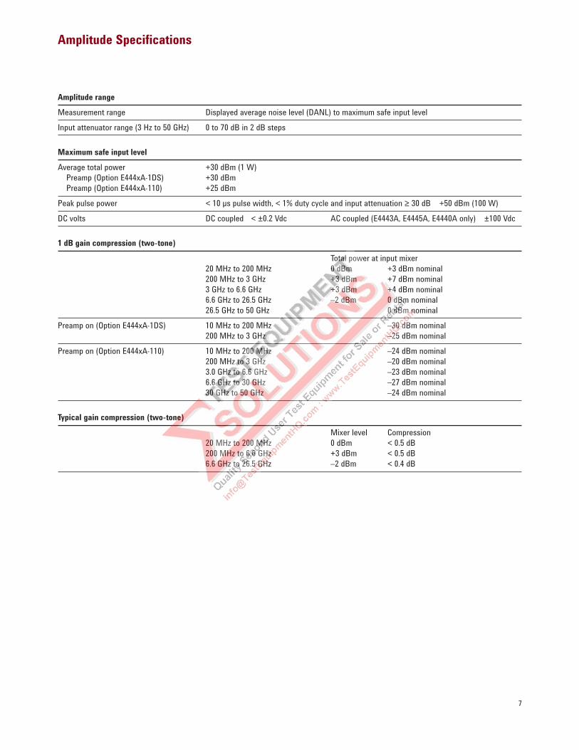
Amplitude Specifications
Amplitude range
Measurement range Displayed average noise level (DANL) to maximum safe input level
Input attenuator range (3 Hz to 50 GHz) 0 to 70 dB in 2 dB steps
Maximum safe input level
Average total power +30 dBm (1 W)
Preamp (Option E444xA-1DS) +30 dBm
Preamp (Option E444xA-110) +25 dBm
Peak pulse power < 10 µs pulse width, < 1% duty cycle and input attenuation ≥ 30 dB +50 dBm (100 W)
DC volts DC coupled < ±0.2 Vdc AC coupled (E4443A, E4445A, E4440A only) ±100 Vdc
1 dB gain compression (two-tone)
Total power at input mixer
20 MHz to 200 MHz 0 dBm +3 dBm nominal
200 MHz to 3 GHz +3 dBm +7 dBm nominal
3 GHz to 6.6 GHz +3 dBm +4 dBm nominal
6.6 GHz to 26.5 GHz –2 dBm 0 dBm nominal
26.5 GHz to 50 GHz 0 dBm nominal
Preamp on (Option E444xA-1DS) 10 MHz to 200 MHz –30 dBm nominal
200 MHz to 3 GHz –25 dBm nominal
Preamp on (Option E444xA-110) 10 MHz to 200 MHz –24 dBm nominal
200 MHz to 3 GHz –20 dBm nominal
3.0 GHz to 6.6 GHz –23 dBm nominal
6.6 GHz to 30 GHz –27 dBm nominal
30 GHz to 50 GHz –24 dBm nominal
Typical gain compression (two-tone)
Mixer level Compression
20 MHz to 200 MHz 0 dBm < 0.5 dB
200 MHz to 6.6 GHz +3 dBm < 0.5 dB
6.6 GHz to 26.5 GHz –2 dBm < 0.4 dB
8
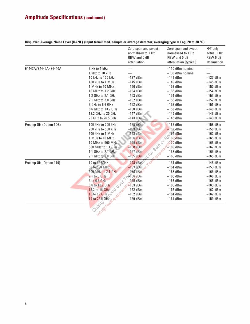
Amplitude Specifications (continued)
Displayed Average Noise Level (DANL) (Input terminated, sample or average detector, averaging type = Log, 20 to 30 °C)
Zero span and swept Zero span and swept FFT only
normalized to 1 Hz normalized to 1 Hz actual 1 Hz
RBW and 0 dB RBW and 0 dB RBW 0 dB
attenuation attenuation (typical) attenuation
E4443A/E4445A/E4440A 3 Hz to 1 kHz — –110 dBm nominal —
1 kHz to 10 kHz — –130 dBm nominal —
10 kHz to 100 kHz –137 dBm –141 dBm –137 dBm
100 kHz to 1 MHz –145 dBm –149 dBm –145 dBm
1 MHz to 10 MHz –150 dBm –153 dBm –150 dBm
10 MHz to 1.2 GHz –154 dBm –155 dBm –154 dBm
1.2 GHz to 2.1 GHz –153 dBm –154 dBm –153 dBm
2.1 GHz to 3.0 GHz –152 dBm –153 dBm –152 dBm
3 GHz to 6.6 GHz –152 dBm –153 dBm –151 dBm
6.6 GHz to 13.2 GHz –150 dBm –152 dBm –149 dBm
13.2 GHz to 20 GHz –147 dBm –149 dBm –146 dBm
20 GHz to 26.5 GHz –143 dBm –145 dBm –143 dBm
Preamp ON (Option 1DS) 100 kHz to 200 kHz –159 dBm –162 dBm –158 dBm
200 kHz to 500 kHz –159 dBm –162 dBm –158 dBm
500 kHz to 1 MHz –163 dBm –165 dBm –162 dBm
1 MHz to 10 MHz –166 dBm –168 dBm –165 dBm
10 MHz to 500 MHz –169 dBm –170 dBm –168 dBm
500 MHz to 1.1 GHz –168 dBm –169 dBm –167 dBm
1.1 GHz to 2.1 GHz –167 dBm –168 dBm –166 dBm
2.1 GHz to 3.0 GHz –165 dBm –166 dBm –165 dBm
Preamp ON (Option 110) 10 to 50 MHz –148 dBm –154 dBm –148 dBm
50 to 500 MHz –153 dBm –164 dBm –153 dBm
500 MHz to 2.1 GHz –166 dBm –168 dBm –166 dBm
2.1 to 3 GHz –166 dBm –168 dBm –166 dBm
3 to 6.6 GHz –165 dBm –166 dBm –165 dBm
6.6 to 13.2 GHz –163 dBm –165 dBm –163 dBm
13.2 to 16 GHz –162 dBm –165 dBm –162 dBm
16 to 19 GHz –162 dBm –164 dBm –162 dBm
19 to 26.5 GHz –159 dBm –161 dBm –159 dBm
9
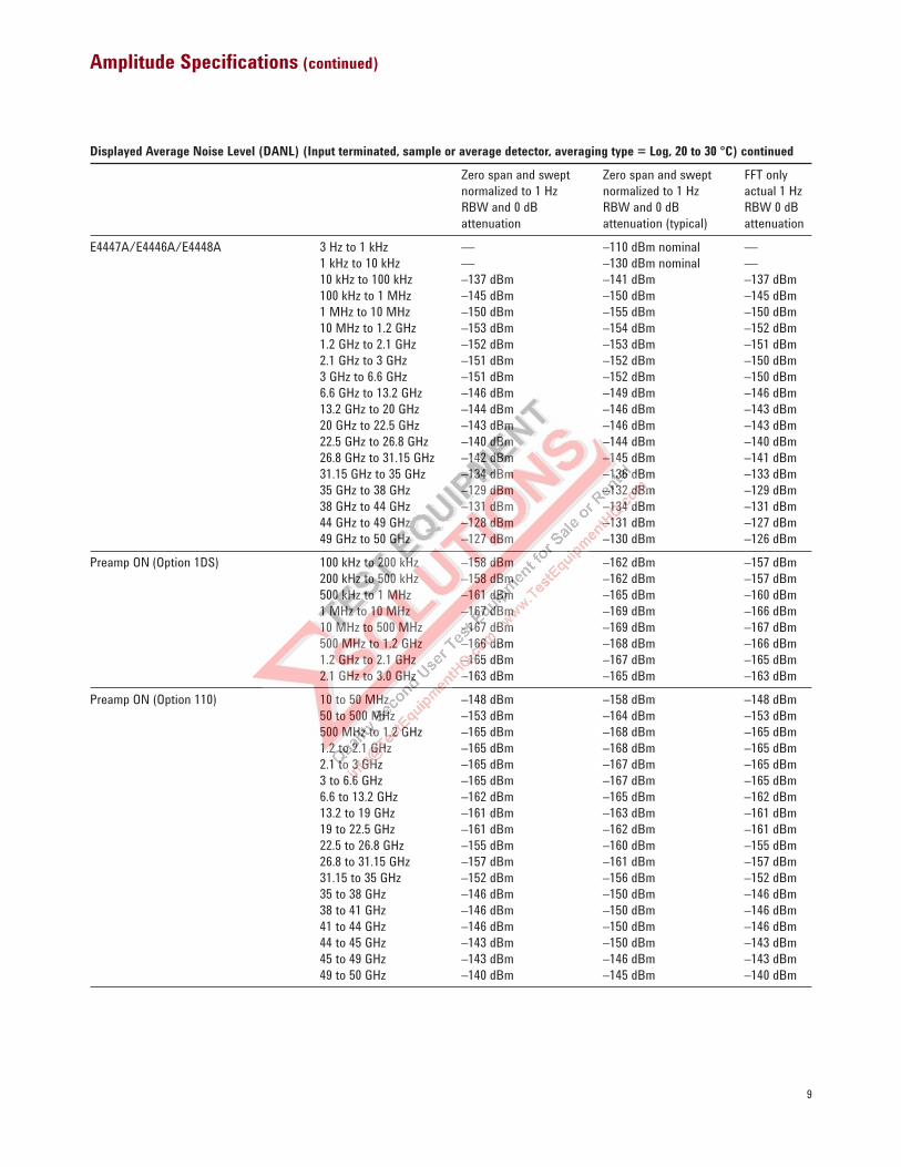
Amplitude Specifications (continued)
Displayed Average Noise Level (DANL) (Input terminated, sample or average detector, averaging type = Log, 20 to 30 °C) continued
Zero span and swept Zero span and swept FFT only
normalized to 1 Hz normalized to 1 Hz actual 1 Hz
RBW and 0 dB RBW and 0 dB RBW 0 dB
attenuation attenuation (typical) attenuation
E4447A/E4446A/E4448A 3 Hz to 1 kHz — –110 dBm nominal —
1 kHz to 10 kHz — –130 dBm nominal —
10 kHz to 100 kHz –137 dBm –141 dBm –137 dBm
100 kHz to 1 MHz –145 dBm –150 dBm –145 dBm
1 MHz to 10 MHz –150 dBm –155 dBm –150 dBm
10 MHz to 1.2 GHz –153 dBm –154 dBm –152 dBm
1.2 GHz to 2.1 GHz –152 dBm –153 dBm –151 dBm
2.1 GHz to 3 GHz –151 dBm –152 dBm –150 dBm
3 GHz to 6.6 GHz –151 dBm –152 dBm –150 dBm
6.6 GHz to 13.2 GHz –146 dBm –149 dBm –146 dBm
13.2 GHz to 20 GHz –144 dBm –146 dBm –143 dBm
20 GHz to 22.5 GHz –143 dBm –146 dBm –143 dBm
22.5 GHz to 26.8 GHz –140 dBm –144 dBm –140 dBm
26.8 GHz to 31.15 GHz –142 dBm –145 dBm –141 dBm
31.15 GHz to 35 GHz –134 dBm –136 dBm –133 dBm
35 GHz to 38 GHz –129 dBm –132 dBm –129 dBm
38 GHz to 44 GHz –131 dBm –134 dBm –131 dBm
44 GHz to 49 GHz –128 dBm –131 dBm –127 dBm
49 GHz to 50 GHz –127 dBm –130 dBm –126 dBm
Preamp ON (Option 1DS) 100 kHz to 200 kHz –158 dBm –162 dBm –157 dBm
200 kHz to 500 kHz –158 dBm –162 dBm –157 dBm
500 kHz to 1 MHz –161 dBm –165 dBm –160 dBm
1 MHz to 10 MHz –167 dBm –169 dBm –166 dBm
10 MHz to 500 MHz –167 dBm –169 dBm –167 dBm
500 MHz to 1.2 GHz –166 dBm –168 dBm –166 dBm
1.2 GHz to 2.1 GHz –165 dBm –167 dBm –165 dBm
2.1 GHz to 3.0 GHz –163 dBm –165 dBm –163 dBm
Preamp ON (Option 110) 10 to 50 MHz –148 dBm –158 dBm –148 dBm
50 to 500 MHz –153 dBm –164 dBm –153 dBm
500 MHz to 1.2 GHz –165 dBm –168 dBm –165 dBm
1.2 to 2.1 GHz –165 dBm –168 dBm –165 dBm
2.1 to 3 GHz –165 dBm –167 dBm –165 dBm
3 to 6.6 GHz –165 dBm –167 dBm –165 dBm
6.6 to 13.2 GHz –162 dBm –165 dBm –162 dBm
13.2 to 19 GHz –161 dBm –163 dBm –161 dBm
19 to 22.5 GHz –161 dBm –162 dBm –161 dBm
22.5 to 26.8 GHz –155 dBm –160 dBm –155 dBm
26.8 to 31.15 GHz –157 dBm –161 dBm –157 dBm
31.15 to 35 GHz –152 dBm –156 dBm –152 dBm
35 to 38 GHz –146 dBm –150 dBm –146 dBm
38 to 41 GHz –146 dBm –150 dBm –146 dBm
41 to 44 GHz –146 dBm –150 dBm –146 dBm
44 to 45 GHz –143 dBm –150 dBm –143 dBm
45 to 49 GHz –143 dBm –146 dBm –143 dBm
49 to 50 GHz –140 dBm –145 dBm –140 dBm
10
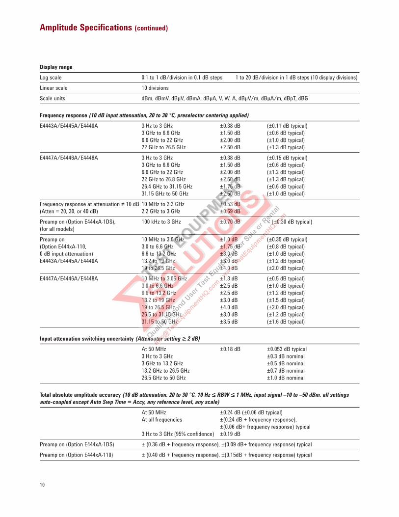
Amplitude Specifications (continued)
Display range
Log scale 0.1 to 1 dB/division in 0.1 dB steps 1 to 20 dB/division in 1 dB steps (10 display divisions)
Linear scale 10 divisions
Scale units dBm, dBmV, dBµV, dBmA, dBµA, V, W, A, dBµV/m, dBµA/m, dBpT, dBG
Frequency response (10 dB input attenuation, 20 to 30 °C, preselector centering applied)
E4443A/E4445A/E4440A 3 Hz to 3 GHz ±0.38 dB (±0.11 dB typical)
3 GHz to 6.6 GHz ±1.50 dB (±0.6 dB typical)
6.6 GHz to 22 GHz ±2.00 dB (±1.0 dB typical)
22 GHz to 26.5 GHz ±2.50 dB (±1.3 dB typical)
E4447A/E4446A/E4448A 3 Hz to 3 GHz ±0.38 dB (±0.15 dB typical)
3 GHz to 6.6 GHz ±1.50 dB (±0.6 dB typical)
6.6 GHz to 22 GHz ±2.00 dB (±1.2 dB typical)
22 GHz to 26.8 GHz ±2.50 dB (±1.3 dB typical)
26.4 GHz to 31.15 GHz ±1.75 dB (±0.6 dB typical)
31.15 GHz to 50 GHz ±2.50 dB (±1.0 dB typical)
Frequency response at attenuation ≠ 10 dB 10 MHz to 2.2 GHz ±0.53 dB
(Atten = 20, 30, or 40 dB) 2.2 GHz to 3 GHz ±0.69 dB
Preamp on (Option E444xA-1DS), 100 kHz to 3 GHz ±0.70 dB < (±0.30 dB typical)
(for all models)
Preamp on 10 MHz to 3.0 GHz ±1.0 dB (±0.35 dB typical)
(Option E444xA-110, 3.0 to 6.6 GHz ±1.75 dB (±0.8 dB typical)
0 dB input attenuation) 6.6 to 13.2 GHz ±3.0 dB (±1.0 dB typical)
E4443A/E4445A/E4440A 13.2 to 19 GHz ±3.0 dB (±1.2 dB typical)
19 to 26.5 GHz ±4.0 dB (±2.0 dB typical)
E4447A/E4446A/E4448A 10 MHz to 3.05 GHz ±1.3 dB (±0.5 dB typical)
3.0 to 6.6 GHz ±2.5 dB (±1.0 dB typical)
6.6 to 13.2 GHz ±2.5 dB (±1.2 dB typical)
13.2 to 19 GHz ±3.0 dB (±1.5 dB typical)
19 to 26.5 GHz ±4.0 dB (±2.0 dB typical)
26.5 to 31.15 GHz ±3.0 dB (±1.2 dB typical)
31.15 to 50 GHz ±3.5 dB (±1.6 dB typical)
Input attenuation switching uncertainty (Attenuator setting ≥ 2 dB)
At 50 MHz ±0.18 dB ±0.053 dB typical
3 Hz to 3 GHz ±0.3 dB nominal
3 GHz to 13.2 GHz ±0.5 dB nominal
13.2 GHz to 26.5 GHz ±0.7 dB nominal
26.5 GHz to 50 GHz ±1.0 dB nominal
Total absolute amplitude accuracy (10 dB attenuation, 20 to 30 °C, 10 Hz ≤ RBW ≤ 1 MHz, input signal –10 to –50 dBm, all settings
auto-coupled except Auto Swp Time = Accy, any reference level, any scale)
At 50 MHz ±0.24 dB (±0.06 dB typical)
At all frequencies ±(0.24 dB + frequency response),
±(0.06 dB+ frequency response) typical
3 Hz to 3 GHz (95% confidence) ±0.19 dB
Preamp on (Option E444xA-1DS) ± (0.36 dB + frequency response), ±(0.09 dB+ frequency response) typical
Preamp on (Option E444xA-110) ± (0.40 dB + frequency response), ±(0.15dB + frequency response) typical
11
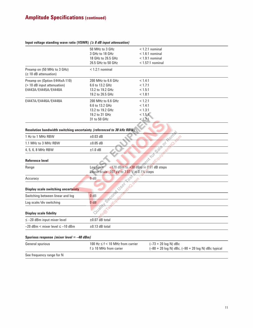
Amplitude Specifications (continued)
Input voltage standing wave ratio (VSWR) (≥ 8 dB input attenuation)
50 MHz to 3 GHz < 1.2:1 nominal
3 GHz to 18 GHz < 1.6:1 nominal
18 GHz to 26.5 GHz < 1.9:1 nominal
26.5 GHz to 50 GHz < 1.57:1 nominal
Preamp on (50 MHz to 3 GHz) < 1.2:1 nominal
(≥ 10 dB attenuation)
Preamp on (Option E444xA-110) 200 MHz to 6.6 GHz < 1.4:1
(> 10 dB input attenuation) 6.6 to 13.2 GHz < 1.7:1
E4443A/E4445A/E4440A 13.2 to 19.2 GHz < 1.5:1
19.2 to 26.5 GHz < 1.8:1
E4447A/E4446A/E4448A 200 MHz to 6.6 GHz < 1.2:1
6.6 to 13.2 GHz < 1.4:1
13.2 to 19.2 GHz < 1.3:1
19.2 to 31 GHz < 1.5:1
31 to 50 GHz < 1.7:1
Resolution bandwidth switching uncertainty (referenced to 30 kHz RBW)
1 Hz to 1 MHz RBW ±0.03 dB
1.1 MHz to 3 MHz RBW ±0.05 dB
4, 5, 6, 8 MHz RBW ±1.0 dB
Reference level
Range Log scale –170 dBm to +30 dBm in 0.01 dB steps
Linear scale 707 pV to 7.07 V in 0.1% steps
Accuracy 0 dB
Display scale switching uncertainty
Switching between linear and log 0 dB
Log scale/div switching 0 dB
Display scale fidelity
≤ –20 dBm input mixer level ±0.07 dB total
–20 dBm < mixer level ≤ –10 dBm ±0.13 dB total
Spurious response (mixer level = –40 dBm)
General spurious 100 Hz ≤ f < 10 MHz from carrier (–73 + 20 log N) dBc
f ≥ 10 MHz from carier (–80 + 20 log N) dBc, (–90 + 20 log N) dBc typical
See frequency range for N
12
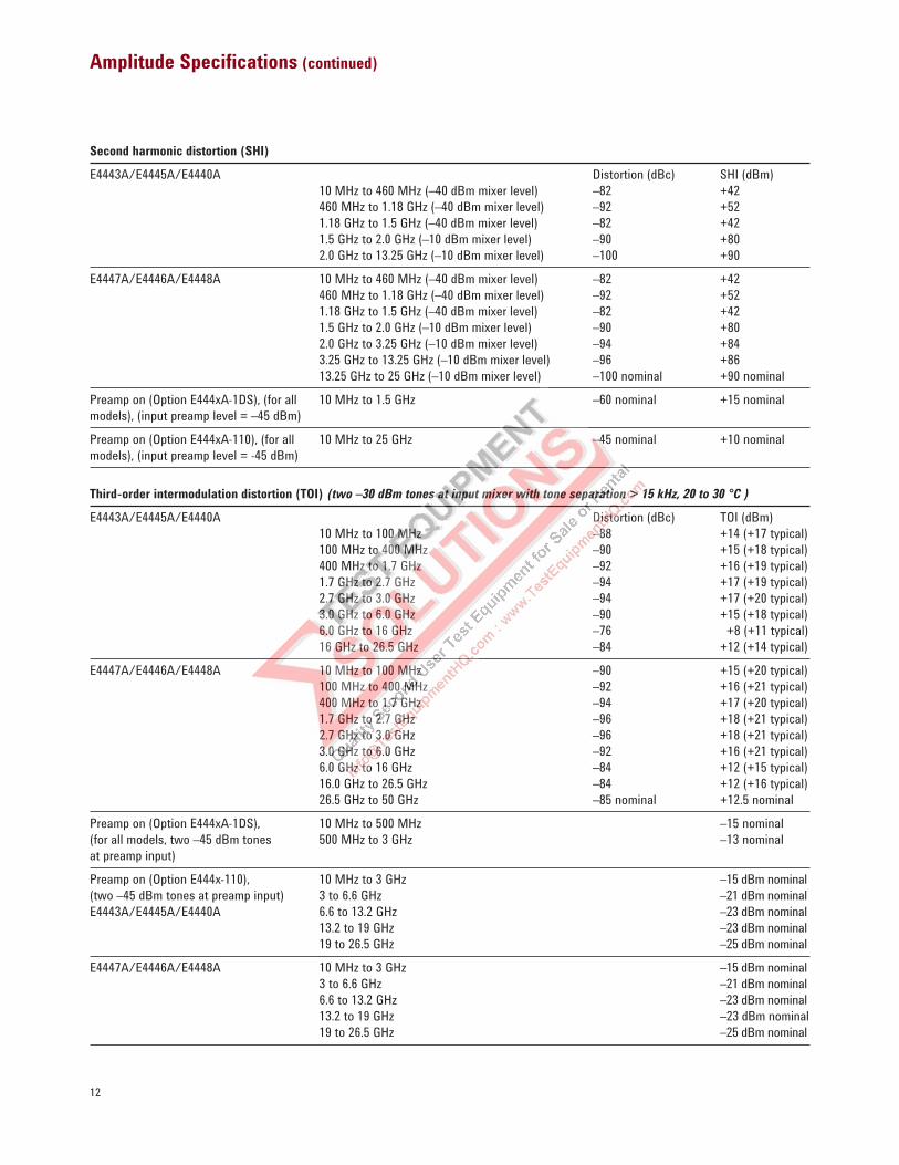
Amplitude Specifications (continued)
Second harmonic distortion (SHI)
E4443A/E4445A/E4440A Distortion (dBc) SHI (dBm)
10 MHz to 460 MHz (–40 dBm mixer level) –82 +42
460 MHz to 1.18 GHz (–40 dBm mixer level) –92 +52
1.18 GHz to 1.5 GHz (–40 dBm mixer level) –82 +42
1.5 GHz to 2.0 GHz (–10 dBm mixer level) –90 +80
2.0 GHz to 13.25 GHz (–10 dBm mixer level) –100 +90
E4447A/E4446A/E4448A 10 MHz to 460 MHz (–40 dBm mixer level) –82 +42
460 MHz to 1.18 GHz (–40 dBm mixer level) –92 +52
1.18 GHz to 1.5 GHz (–40 dBm mixer level) –82 +42
1.5 GHz to 2.0 GHz (–10 dBm mixer level) –90 +80
2.0 GHz to 3.25 GHz (–10 dBm mixer level) –94 +84
3.25 GHz to 13.25 GHz (–10 dBm mixer level) –96 +86
13.25 GHz to 25 GHz (–10 dBm mixer level) –100 nominal +90 nominal
Preamp on (Option E444xA-1DS), (for all 10 MHz to 1.5 GHz –60 nominal +15 nominal
models), (input preamp level = –45 dBm)
Preamp on (Option E444xA-110), (for all 10 MHz to 25 GHz –45 nominal +10 nominal
models), (input preamp level = -45 dBm)
Third-order intermodulation distortion (TOI) (two –30 dBm tones at input mixer with tone separation > 15 kHz, 20 to 30 °C )
E4443A/E4445A/E4440A Distortion (dBc) TOI (dBm)
10 MHz to 100 MHz –88 +14 (+17 typical)
100 MHz to 400 MHz –90 +15 (+18 typical)
400 MHz to 1.7 GHz –92 +16 (+19 typical)
1.7 GHz to 2.7 GHz –94 +17 (+19 typical)
2.7 GHz to 3.0 GHz –94 +17 (+20 typical)
3.0 GHz to 6.0 GHz –90 +15 (+18 typical)
6.0 GHz to 16 GHz –76 +8 (+11 typical)
16 GHz to 26.5 GHz –84 +12 (+14 typical)
E4447A/E4446A/E4448A 10 MHz to 100 MHz –90 +15 (+20 typical)
100 MHz to 400 MHz –92 +16 (+21 typical)
400 MHz to 1.7 GHz –94 +17 (+20 typical)
1.7 GHz to 2.7 GHz –96 +18 (+21 typical)
2.7 GHz to 3.0 GHz –96 +18 (+21 typical)
3.0 GHz to 6.0 GHz –92 +16 (+21 typical)
6.0 GHz to 16 GHz –84 +12 (+15 typical)
16.0 GHz to 26.5 GHz –84 +12 (+16 typical)
26.5 GHz to 50 GHz –85 nominal +12.5 nominal
Preamp on (Option E444xA-1DS), 10 MHz to 500 MHz –15 nominal
(for all models, two –45 dBm tones 500 MHz to 3 GHz –13 nominal
at preamp input)
Preamp on (Option E444x-110), 10 MHz to 3 GHz –15 dBm nominal
(two –45 dBm tones at preamp input) 3 to 6.6 GHz –21 dBm nominal
E4443A/E4445A/E4440A 6.6 to 13.2 GHz –23 dBm nominal
13.2 to 19 GHz –23 dBm nominal
19 to 26.5 GHz –25 dBm nominal
E4447A/E4446A/E4448A 10 MHz to 3 GHz –15 dBm nominal
3 to 6.6 GHz –21 dBm nominal
6.6 to 13.2 GHz –23 dBm nominal
13.2 to 19 GHz –23 dBm nominal
19 to 26.5 GHz –25 dBm nominal
13
Amplitude Specifications (continued)
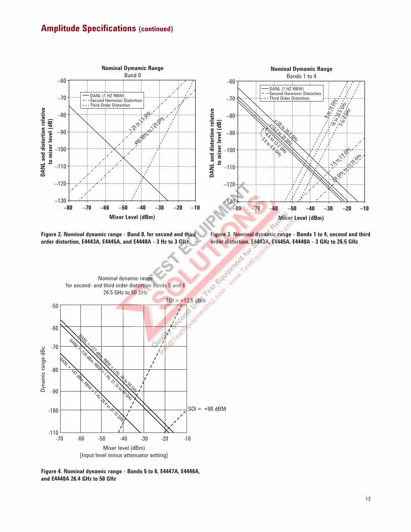
Nominal Dymamic Range
Band 0
DA
NL
and d
isto
rtio
n r
elati
ve
to m
ixer
lev
el (
dB
)
–60
–70
–80
–90
–100
–110
–120
–130
Mixer Level (dBm)
–80 –70 –60 –50 –40 –30 –20 –10
DANL (1 HZ RBW)Second Harmonic DistortionThird Order Distortion
1.25 t
o 1.5 G
Hz
400 M
Hz to 1.2
5 GHz
Nominal Dymamic Range
Bands 1 to 4
DA
NL
and d
isto
rtio
n r
elati
ve
to m
ixer
lev
el (
dB
)
–60
–70
–80
–90
–100
–110
–120
–130
Mixer Level (dBm)
–80 –70 –60 –50 –40 –30 –20 –10
DANL (1 HZ RBW)Second Harmonic DistortionThird Order Distortion
1.5 to
2.0 GHz
6 to 1
6 GHz
20 to 26.5 GHz
13.2 to 20 GHz
6.6 to 13.2 GHz
3.0 to 6.6 GHz
16 to
26.5
GHz
3 to 6
GHz
2.0 GHz to
13.25
GHz
Figure 2. Nominal dynamic range - Band 0, for second and third
order distortion, E4443A, E4445A, and E4440A - 3 Hz to 3 GHz
Figure 3. Nominal dynamic range - Bands 1 to 4, second and third
order distortion, E4443A, E4445A, E4440A - 3 GHz to 26.5 GHz
Nominal dynamic range
for second- and third-order distortion bands 5 and 6
26.5 GHz to 50 GHz
Dyn
amic
ran
ge d
Bc
Mixer level (dBm)
[Input level minus attenuator setting]
SOI = +90 dBM
TOI = +12.5 dBm
DANL = -127 dBm, RBW
= 1 Hz, 44 to 50 GHz
DANL = -129 dBm, RBW
= 1 Hz, 31.15 to 44 GHz
DANL = -141 dBm, RBW
= 1 Hz, 26.4 to 31.15 GHz
-110-70 -60 -50 -40 -30 -20 -10
-100
-90
-80
-70
-60
-50
Figure 4. Nominal dynamic range - Bands 5 to 6, E4447A, E4446A,
and E4448A 26.4 GHz to 50 GHz
14
Amplitude Specifications (continued)
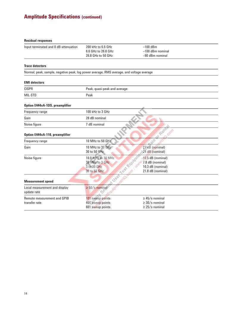
Residual responses
Input terminated and 0 dB attenuation 200 kHz to 6.6 GHz –100 dBm
6.6 GHz to 26.8 GHz –100 dBm nominal
26.8 GHz to 50 GHz –90 dBm nominal
Trace detectors
Normal, peak, sample, negative peak, log power average, RMS average, and voltage average
EMI detectors
CISPR Peak, quasi-peak and average
MIL-STD Peak
Option E444xA-1DS, preamplifier
Frequency range 100 kHz to 3 GHz
Gain 28 dB nominal
Noise figure 7 dB nominal
Option E444xA-110, preamplifier
Frequency range 10 MHz to 50 GHz
Gain 10 MHz to 30 GHz 27 dB (nominal)
30 to 50 GHz 24 dB (nominal)
Noise figure 10.0 MHz to 30 MHz 12.5 dB (nominal)
30 MHz to 3 GHz 7.8 dB (nominal)
3 to 30 GHz 10.3 dB (nominal)
30 to 50 GHz 21.8 dB (nominal)
Measurement speed
Local measurement and display ≥ 50/s nominal
update rate
Remote measurement and GPIB 101 sweep points ≥ 45/s nominal
transfer rate 401 sweep points ≥ 30/s nominal
601 sweep points ≥ 25/s nominal
15
Other Specifications
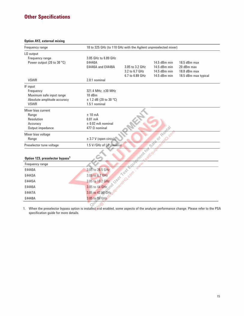
Option AYZ, external mixing
Frequency range 18 to 325 GHz (to 110 GHz with the Agilent unpreselected mixer)
LO output
Frequency range 3.05 GHz to 6.89 GHz
Power output (20 to 30 °C) E4440A 14.5 dBm min 18.5 dBm max
E4446A and E4448A 3.05 to 3.2 GHz 14.5 dBm min 20 dBm max
3.2 to 6.7 GHz 14.5 dBm min 18.8 dBm max
6.7 to 6.89 GHz 14.5 dBm min 18.5 dBm max typical
VSWR 2.0:1 nominal
IF input
Frequency 321.4 MHz, ±30 MHz
Maximum safe input range 10 dBm
Absolute amplitude accuracy ± 1.2 dB (20 to 30 °C)
VSWR 1.5:1 nominal
Mixer bias current
Range ± 10 mA
Resolution 0.01 mA
Accuracy ± 0.02 mA nominal
Output impedance 477 Ω nominal
Mixer bias voltage
Range ± 3.7 V (open circuit)
Preselector tune voltage 1.5 V/GHz of LO nominal
Option 123, preselector bypass1
Frequency range
E4440A 3.05 to 26.5 GHz
E4443A 3.05 to 6.7 GHz
E4445A 3.05 to 13.2 GHz
E4446A 3.05 to 44 GHz
E4447A 3.05 to 42.98 GHz
E4448A 3.05 to 50 GHz
1. When the preselector bypass option is installed and enabled, some aspects of the analyzer performance change. Please refer to the PSA
specifi cation guide for more details.
16
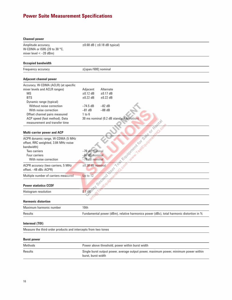
Power Suite Measurement Specifications
Channel power
Amplitude accuracy, ±0.68 dB ( ±0.18 dB typical)
W-CDMA or IS95 (20 to 30 °C,
mixer level < –20 dBm)
Occupied bandwidth
Frequency accuracy ±[span/600] nominal
Adjacent channel power
Accuracy, W-CDMA (ACLR) (at specific
mixer levels and ACLR ranges) Adjacent Alternate
MS ±0.12 dB ±0.17 dB
BTS ±0.22 dB ±0.22 dB
Dynamic range (typical)
Without noise correction –74.5 dB –82 dB
With noise correction –81 dB –88 dB
Offset channel pairs measured 1 to 6
ACP speed (fast method). Data 30 ms nominal (0.2 dB standard deviation)
measurement and transfer time
Multi-carrier power and ACP
ACPR dynamic range, W-CDMA (5 MHz
offset, RRC weighted, 3.84 MHz noise
bandwidth)
Two carriers –70 dB nominal
Four carriers –66 dB nominal
With noise correction –76 dB nominal
ACPR accuracy (two carriers, 5 MHz ±0.38 dB nominal
offset, –48 dBc ACPR)
Multiple number of carriers measured Up to 12
Power statistics CCDF
Histogram resolution 0.1 dB
Harmonic distortion
Maximum harmonic number 10th
Results Fundamental power (dBm), relative harmonics power (dBc), total harmonic distortion in %
Intermod (TOI)
Measure the third-order products and intercepts from two tones
Burst power
Methods Power above threshold, power within burst width
Results Single burst output power, average output power, maximum power, minimum power within
burst, burst width
17
Power Suite Measurement Specifications (continued)
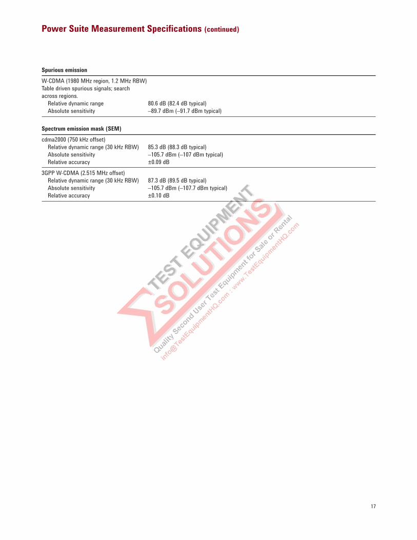
Spurious emission
W-CDMA (1980 MHz region, 1.2 MHz RBW)
Table driven spurious signals; search
across regions.
Relative dynamic range 80.6 dB (82.4 dB typical)
Absolute sensitivity –89.7 dBm (–91.7 dBm typical)
Spectrum emission mask (SEM)
cdma2000 (750 kHz offset)
Relative dynamic range (30 kHz RBW) 85.3 dB (88.3 dB typical)
Absolute sensitivity –105.7 dBm (–107 dBm typical)
Relative accuracy ±0.09 dB
3GPP W-CDMA (2.515 MHz offset)
Relative dynamic range (30 kHz RBW) 87.3 dB (89.5 dB typical)
Absolute sensitivity –105.7 dBm (–107.7 dBm typical)
Relative accuracy ±0.10 dB
18
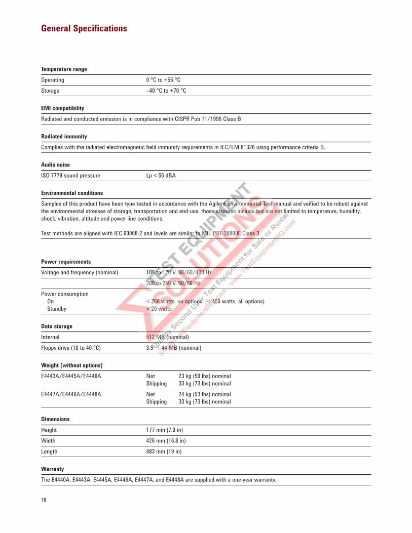
General Specifications
Temperature range
Operating 0 °C to +55 °C
Storage –40 °C to +70 °C
EMI compatibility
Radiated and conducted emission is in compliance with CISPR Pub 11/1996 Class B
Radiated immunity
Complies with the radiated electromagnetic field immunity requirements in IEC/EM 61326 using performance criteria B.
Audio noise
ISO 7779 sound pressure Lp < 55 dBA
Environmental conditions
Samples of this product have been type tested in accordance with the Agilent Environmental Test manual and veified to be robust against
the environmental stresses of storage, transportation and end-use, those stresses include but are not limited to temperature, humidity,
shock, vibration, altitude and power line conditions.
Test methods are aligned with IEC 60068-2 and levels are similar to MIL-PRF-28800F Class 3.
Power requirements
Voltage and frequency (nominal) 100 to 120 V, 50/60/400 Hz
200 to 240 V, 50/60 Hz
Power consumption
On < 260 watts, no options, (< 450 watts, all options)
Standby < 20 watts
Data storage
Internal 512 MB (nominal)
Floppy drive (10 to 40 °C) 3.5” 1.44 MB (nominal)
Weight (without options)
E4443A/E4445A/E4440A Net 23 kg (50 lbs) nominal
Shipping 33 kg (73 lbs) nominal
E4447A/E4446A/E4448A Net 24 kg (53 lbs) nominal
Shipping 33 kg (73 lbs) nominal
Dimensions
Height 177 mm (7.0 in)
Width 426 mm (16.8 in)
Length 483 mm (19 in)
Warranty
The E4440A, E4443A, E4445A, E4446A, E4447A, and E4448A are supplied with a one-year warranty.
19
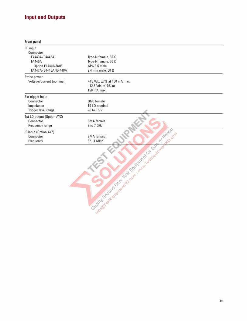
Input and Outputs
Front panel
RF input
Connector
E4443A/E4445A Type-N female, 50 Ω
E4440A Type-N female, 50 Ω
Option E4440A-BAB APC 3.5 male
E4447A/E4446A/E4448A 2.4 mm male, 50 Ω
Probe power
Voltage/current (nominal) +15 Vdc, ±7% at 150 mA max
–12.6 Vdc, ±10% at
150 mA max
Ext trigger input
Connector BNC female
Impedance 10 kΩ nominal
Trigger level range –5 to +5 V
1st LO output (Option AYZ)
Connector SMA female
Frequency range 3 to 7 GHz
IF input (Option AYZ)
Connector SMA female
Frequency 321.4 MHz
20
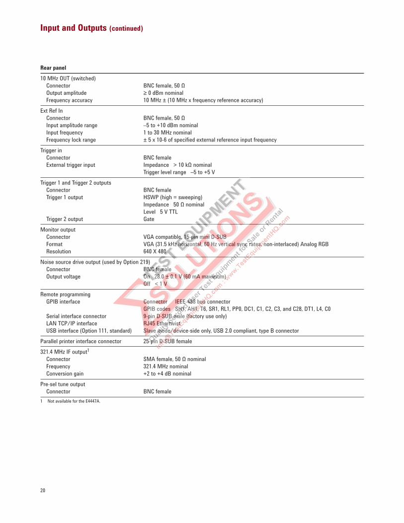
Input and Outputs (continued)
Rear panel
10 MHz OUT (switched)
Connector BNC female, 50 Ω
Output amplitude ≥ 0 dBm nominal
Frequency accuracy 10 MHz ± (10 MHz x frequency reference accuracy)
Ext Ref In
Connector BNC female, 50 Ω
Input amplitude range –5 to +10 dBm nominal
Input frequency 1 to 30 MHz nominal
Frequency lock range ± 5 x 10⁻⁶ of specified external reference input frequency
Trigger in
Connector BNC female
External trigger input Impedance > 10 kΩ nominal
Trigger level range –5 to +5 V
Trigger 1 and Trigger 2 outputs
Connector BNC female
Trigger 1 output HSWP (high = sweeping)
Impedance 50 Ω nominal
Level 5 V TTL
Trigger 2 output Gate
Monitor output
Connector VGA compatible, 15-pin mini D-SUB
Format VGA (31.5 kHz horizontal, 60 Hz vertical sync rates, non-interlaced) Analog RGB
Resolution 640 X 480
Noise source drive output (used by Option 219)
Connector BNC female
Output voltage On 28.0 ± 0.1 V (60 mA maximum)
Off < 1 V
Remote programming
GPIB interface Connector IEEE-488 bus connector
GPIB codes SH1, AH1, T6, SR1, RL1, PP0, DC1, C1, C2, C3, and C28, DT1, L4, C0
Serial interface connector 9-pin D-SUB male (factory use only)
LAN TCP/IP interface RJ45 Ethertwist
USB interface (Option 111, standard) Slave mode/device-side only, USB 2.0 compliant, type B connector
Parallel printer interface connector 25-pin D-SUB female
321.4 MHz IF output1
Connector SMA female, 50 Ω nominal
Frequency 321.4 MHz nominal
Conversion gain +2 to +4 dB nominal
Pre-sel tune output
Connector BNC female
1 Not available for the E4447A.
21
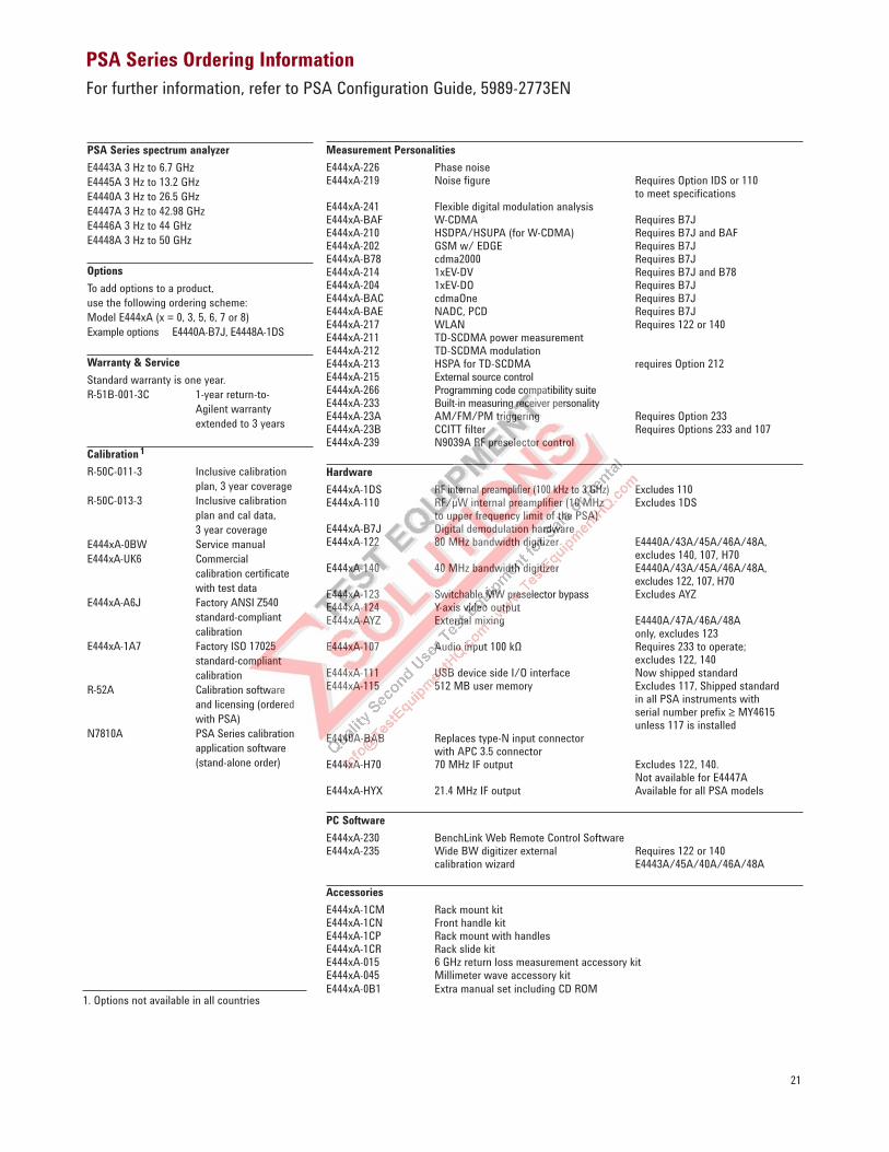
PSA Series Ordering Information
For further information, refer to PSA Configuration Guide, 5989-2773EN
Measurement Personalities
E444xA-226 Phase noise E444xA-219 Noise figure Requires Option IDS or 110 to meet specifications E444xA-241 Flexible digital modulation analysisE444xA-BAF W-CDMA Requires B7JE444xA-210 HSDPA/HSUPA (for W-CDMA) Requires B7J and BAFE444xA-202 GSM w/ EDGE Requires B7JE444xA-B78 cdma2000 Requires B7JE444xA-214 1xEV-DV Requires B7J and B78E444xA-204 1xEV-DO Requires B7JE444xA-BAC cdmaOne Requires B7JE444xA-BAE NADC, PCD Requires B7JE444xA-217 WLAN Requires 122 or 140E444xA-211 TD-SCDMA power measurement E444xA-212 TD-SCDMA modulationE444xA-213 HSPA for TD-SCDMA requires Option 212E444xA-215 External source controlE444xA-266 Programming code compatibility suite E444xA-233 Built-in measuring receiver personalityE444xA-23A AM/FM/PM triggering Requires Option 233E444xA-23B CCITT filter Requires Options 233 and 107 E444xA-239 N9039A RF preselector control
Hardware
E444xA-1DS RF internal preamplifier (100 kHz to 3 GHz) Excludes 110E444xA-110 RF/µW internal preamplifier (10 MHz Excludes 1DS to upper frequency limit of the PSA)E444xA-B7J Digital demodulation hardwareE444xA-122 80 MHz bandwidth digitizer E4440A/43A/45A/46A/48A, excludes 140, 107, H70E444xA-140 40 MHz bandwidth digitizer E4440A/43A/45A/46A/48A, excludes 122, 107, H70 E444xA-123 Switchable MW preselector bypass Excludes AYZE444xA-124 Y-axis video outputE444xA-AYZ External mixing E4440A/47A/46A/48A only, excludes 123 E444xA-107 Audio input 100 kΩ Requires 233 to operate; excludes 122, 140 E444xA-111 USB device side I/O interface Now shipped standardE444xA-115 512 MB user memory Excludes 117, Shipped standard in all PSA instruments with serial number prefix ≥ MY4615 unless 117 is installedE4440A-BAB Replaces type-N input connector with APC 3.5 connector E444xA-H70 70 MHz IF output Excludes 122, 140. Not available for E4447AE444xA-HYX 21.4 MHz IF output Available for all PSA models
PC Software
E444xA-230 BenchLink Web Remote Control SoftwareE444xA-235 Wide BW digitizer external Requires 122 or 140 calibration wizard E4443A/45A/40A/46A/48A
Accessories
E444xA-1CM Rack mount kit E444xA-1CN Front handle kit E444xA-1CP Rack mount with handles E444xA-1CR Rack slide kit E444xA-015 6 GHz return loss measurement accessory kitE444xA-045 Millimeter wave accessory kit E444xA-0B1 Extra manual set including CD ROM
1. Options not available in all countries
PSA Series spectrum analyzer
E4443A 3 Hz to 6.7 GHz
E4445A 3 Hz to 13.2 GHz
E4440A 3 Hz to 26.5 GHz
E4447A 3 Hz to 42.98 GHz
E4446A 3 Hz to 44 GHz
E4448A 3 Hz to 50 GHz
Options
To add options to a product,
use the following ordering scheme:
Model E444xA (x = 0, 3, 5, 6, 7 or 8)
Example options E4440A-B7J, E4448A-1DS
Warranty & Service
Standard warranty is one year.
R-51B-001-3C 1-year return-to-
Agilent warranty
extended to 3 years
Calibration 1
R-50C-011-3 Inclusive calibration
plan, 3 year coverage
R-50C-013-3 Inclusive calibration
plan and cal data,
3 year coverage
E444xA-0BW Service manual
E444xA-UK6 Commercial
calibration certificate
with test data
E444xA-A6J Factory ANSI Z540
standard-compliant
calibration
E444xA-1A7 Factory ISO 17025
standard-compliant
calibration
R-52A Calibration software
and licensing (ordered
with PSA)
N7810A PSA Series calibration
application software
(stand-alone order)
22
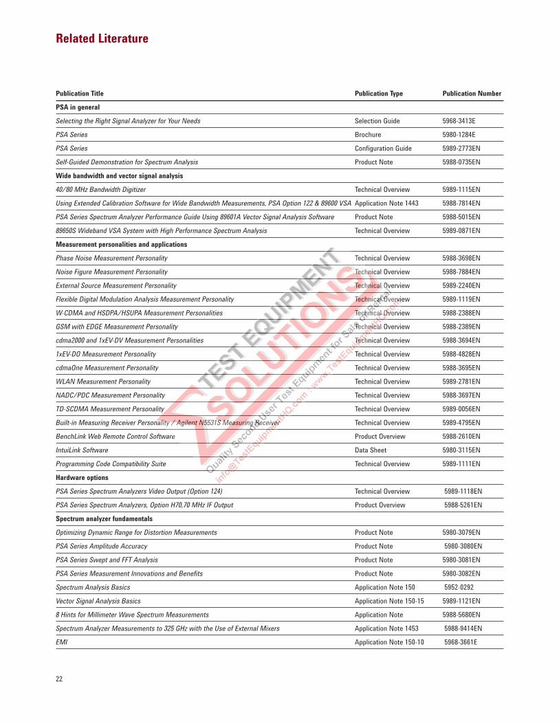
Publication Title Publication Type Publication Number
PSA in general
Selecting the Right Signal Analyzer for Your Needs Selection Guide 5968-3413E
PSA Series Brochure 5980-1284E
PSA Series Configuration Guide 5989-2773EN
Self-Guided Demonstration for Spectrum Analysis Product Note 5988-0735EN
Wide bandwidth and vector signal analysis
40/80 MHz Bandwidth Digitizer Technical Overview 5989-1115EN
Using Extended Calibration Software for Wide Bandwidth Measurements, PSA Option 122 & 89600 VSA Application Note 1443 5988-7814EN
PSA Series Spectrum Analyzer Performance Guide Using 89601A Vector Signal Analysis Software Product Note 5988-5015EN
89650S Wideband VSA System with High Performance Spectrum Analysis Technical Overview 5989-0871EN
Measurement personalities and applications
Phase Noise Measurement Personality Technical Overview 5988-3698EN
Noise Figure Measurement Personality Technical Overview 5988-7884EN
External Source Measurement Personality Technical Overview 5989-2240EN
Flexible Digital Modulation Analysis Measurement Personality Technical Overview 5989-1119EN
W-CDMA and HSDPA/HSUPA Measurement Personalities Technical Overview 5988-2388EN
GSM with EDGE Measurement Personality Technical Overview 5988-2389EN
cdma2000 and 1xEV-DV Measurement Personalities Technical Overview 5988-3694EN
1xEV-DO Measurement Personality Technical Overview 5988-4828EN
cdmaOne Measurement Personality Technical Overview 5988-3695EN
WLAN Measurement Personality Technical Overview 5989-2781EN
NADC/PDC Measurement Personality Technical Overview 5988-3697EN
TD-SCDMA Measurement Personality Technical Overview 5989-0056EN
Built-in Measuring Receiver Personality / Agilent N5531S Measuring Receiver Technical Overview 5989-4795EN
BenchLink Web Remote Control Software Product Overview 5988-2610EN
IntuiLink Software Data Sheet 5980-3115EN
Programming Code Compatibility Suite Technical Overview 5989-1111EN
Hardware options
PSA Series Spectrum Analyzers Video Output (Option 124) Technical Overview 5989-1118EN
PSA Series Spectrum Analyzers, Option H70,70 MHz IF Output Product Overview 5988-5261EN
Spectrum analyzer fundamentals
Optimizing Dynamic Range for Distortion Measurements Product Note 5980-3079EN
PSA Series Amplitude Accuracy Product Note 5980-3080EN
PSA Series Swept and FFT Analysis Product Note 5980-3081EN
PSA Series Measurement Innovations and Benefits Product Note 5980-3082EN
Spectrum Analysis Basics Application Note 150 5952-0292
Vector Signal Analysis Basics Application Note 150-15 5989-1121EN
8 Hints for Millimeter Wave Spectrum Measurements Application Note 5988-5680EN
Spectrum Analyzer Measurements to 325 GHz with the Use of External Mixers Application Note 1453 5988-9414EN
EMI Application Note 150-10 5968-3661E
Related Literature
www.agilent.com/find/psa
www.agilent.com/fi nd/emailupdates
Get the latest information on the
products and applications you select.
www.agilent.com/fi nd/agilentdirect
Quickly choose and use your test
equipment solutions with confi dence.
Remove all doubt
Our repair and calibration services
will get your equipment back to you,
performing like new, when prom-
ised. You will get full value out of
your Agilent equipment through-
out its lifetime. Your equipment
will be serviced by Agilent-trained
technicians using the latest factory
calibration procedures, automated
repair diagnostics and genuine parts.
You will always have the utmost
confi dence in your measurements.
Agilent offers a wide range of
additional expert test and measure-
ment services for your equipment,
including initial start-up assistance
onsite education and training, as
well as design, system integration,
and project management.
For more information on repair and
calibration services, go to:
www.agilent.com/fi nd/open
Agilent Open simplifi es the process
of connecting and programming
test systems to help engineers
design, validate and manufacture
electronic products. Agilent offers
open connectivity for a broad range
of system-ready instruments, open
industry software, PC-standard I/O
and global support, which are
combined to more easily integrate
test system development.
www.agilent.com/fi nd/removealldoubt
www.agilent.com
For more information on Agilent Technologies’
products, applications or services, please
contact your local Agilent office. The
complete list is available at:
www.agilent.com/fi nd/contactus
Americas
Canada (877) 894-4414
Latin America 305 269 7500
United States (800) 829-4444
Asia Pacifi c
Australia 1 800 629 485
China 800 810 0189
Hong Kong 800 938 693
India 1 800 112 929
Japan 0120 (421) 345
Korea 080 769 0800
Malaysia 1 800 888 848
Singapore 1 800 375 8100
Taiwan 0800 047 866
Thailand 1 800 226 008
Europe & Middle East
Austria 01 36027 71571
Belgium 32 (0) 2 404 93 40
Denmark 45 70 13 15 15
Finland 358 (0) 10 855 2100
France 0825 010 700*
*0.125 €/minute
Germany 07031 464 6333**
**0.14 €/minute
Ireland 1890 924 204
Israel 972-3-9288-504/544
Italy 39 02 92 60 8484
Netherlands 31 (0) 20 547 2111
Spain 34 (91) 631 3300
Sweden 0200-88 22 55
Switzerland 0800 80 53 53
United Kingdom 44 (0) 118 9276201
Other European Countries:
www.agilent.com/fi nd/contactus
Revised: July 17, 2008
Product specifi cations and descriptions
in this document subject to change
without notice.
© Agilent Technologies, Inc. 2005-2008
Printed in USA, August 11, 2008
5980-1284E