Embed Size (px)
Citation preview
Biamp Systems, 9300 SW Gemini Drive, Beaverton, Oregon 97008 U.S.A. (503) 641-7287 www.biamp.com
TesiraFORTÉ
Fixed I/O Server Devices
Operation Manual
April 2014
2
TABLE OF CONTENTS
TesiraFORTÉ . . . . . . . . . . . . . . . . . . . . . . . . . . . . . . . . . . . . . . . . . . . . . . . . . . . . . . . . . . . . . . .4BENEFITS . . . . . . . . . . . . . . . . . . . . . . . . . . . . . . . . . . . . . . . . . . . . . . . . . . . . . . . . . . . . . . . . . . . . . . . . . . . . . .4COMMON FEATURES . . . . . . . . . . . . . . . . . . . . . . . . . . . . . . . . . . . . . . . . . . . . . . . . . . . . . . . . . . . . . . . . . . . . .5AVB AI AND AI . . . . . . . . . . . . . . . . . . . . . . . . . . . . . . . . . . . . . . . . . . . . . . . . . . . . . . . . . . . . . . . . . . . . . . . . . . .5AVB CI AND CI . . . . . . . . . . . . . . . . . . . . . . . . . . . . . . . . . . . . . . . . . . . . . . . . . . . . . . . . . . . . . . . . . . . . . . . . . . .5AVB TI AND TI . . . . . . . . . . . . . . . . . . . . . . . . . . . . . . . . . . . . . . . . . . . . . . . . . . . . . . . . . . . . . . . . . . . . . . . . . . .5AVB VI AND VI . . . . . . . . . . . . . . . . . . . . . . . . . . . . . . . . . . . . . . . . . . . . . . . . . . . . . . . . . . . . . . . . . . . . . . . . . . .5
TesiraFORTÉ FRONT PANEL . . . . . . . . . . . . . . . . . . . . . . . . . . . . . . . . . . . . . . . . . . . . . . . . . .6VENTILATION . . . . . . . . . . . . . . . . . . . . . . . . . . . . . . . . . . . . . . . . . . . . . . . . . . . . . . . . . . . . . . . . . . . . . . . . . . .6DISPLAY NAVIGATION BUTTONS . . . . . . . . . . . . . . . . . . . . . . . . . . . . . . . . . . . . . . . . . . . . . . . . . . . . . . . . . . .6LED STATUS INDICATORS . . . . . . . . . . . . . . . . . . . . . . . . . . . . . . . . . . . . . . . . . . . . . . . . . . . . . . . . . . . . . . . . .6OLED DISPLAY . . . . . . . . . . . . . . . . . . . . . . . . . . . . . . . . . . . . . . . . . . . . . . . . . . . . . . . . . . . . . . . . . . . . . . . . . .7
Home Screen . . . . . . . . . . . . . . . . . . . . . . . . . . . . . . . . . . . . . . . . . . . . . . . . . . . . . . . . . . . . . . . . . . . . . . . . . .7Menu Screen . . . . . . . . . . . . . . . . . . . . . . . . . . . . . . . . . . . . . . . . . . . . . . . . . . . . . . . . . . . . . . . . . . . . . . . . . .7Faults . . . . . . . . . . . . . . . . . . . . . . . . . . . . . . . . . . . . . . . . . . . . . . . . . . . . . . . . . . . . . . . . . . . . . . . . . . . . . . . .8Edit Timeouts . . . . . . . . . . . . . . . . . . . . . . . . . . . . . . . . . . . . . . . . . . . . . . . . . . . . . . . . . . . . . . . . . . . . . . . . . .8Localization . . . . . . . . . . . . . . . . . . . . . . . . . . . . . . . . . . . . . . . . . . . . . . . . . . . . . . . . . . . . . . . . . . . . . . . . . . . .8
TesiraFORTÉ AVB AI REAR PANEL . . . . . . . . . . . . . . . . . . . . . . . . . . . . . . . . . . . . . . . . . . . . .9
QUICK START . . . . . . . . . . . . . . . . . . . . . . . . . . . . . . . . . . . . . . . . . . . . . . . . . . . . . . . . . . . . .10PREREQUISITES . . . . . . . . . . . . . . . . . . . . . . . . . . . . . . . . . . . . . . . . . . . . . . . . . . . . . . . . . . . . . . . . . . . . . . . .10CONNECTING TO THE TESIRAFORTÉ SYSTEM . . . . . . . . . . . . . . . . . . . . . . . . . . . . . . . . . . . . . . . . . . . . . .10SETTING AN IP ADDRESS . . . . . . . . . . . . . . . . . . . . . . . . . . . . . . . . . . . . . . . . . . . . . . . . . . . . . . . . . . . . . . . . 11
Assigning an IP Address to your computer . . . . . . . . . . . . . . . . . . . . . . . . . . . . . . . . . . . . . . . . . . . . . . . . . . . 11Auto assignment of IP Address using DHCP . . . . . . . . . . . . . . . . . . . . . . . . . . . . . . . . . . . . . . . . . . . . . . . . .12
SPECIFICATIONS . . . . . . . . . . . . . . . . . . . . . . . . . . . . . . . . . . . . . . . . . . . . . . . . . . . . . . . . . . .13
WARRANTY . . . . . . . . . . . . . . . . . . . . . . . . . . . . . . . . . . . . . . . . . . . . . . . . . . . . . . . . . . . . . . .15
COMPLIANCE . . . . . . . . . . . . . . . . . . . . . . . . . . . . . . . . . . . . . . . . . . . . . . . . . . . . . . . . . . . . .16
EC DECLARATION OF CONFORMITY . . . . . . . . . . . . . . . . . . . . . . . . . . . . . . . . . . . . . . . . . .18
ROHS COMPLIANCE AND HAZARDOUS SUBSTANCE TABLE . . . . . . . . . . . . . . . . . . . . .19
33
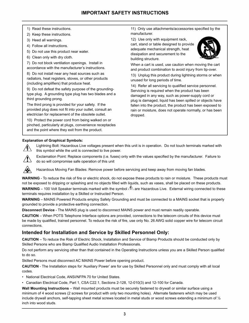
IMPORTANT SAFETY INSTRUCTIONS
Lightning Bolt: Hazardous Live voltages present when this unit is in operation . Do not touch terminals marked with this symbol while the unit is connected to live power .Exclamation Point: Replace components (i.e. fuses) only with the values specified by the manufacturer. Failure to do so will compromise safe operation of this unit
Hazardous Moving Fan Blades: Remove power before servicing and keep away from moving fan blades .
WARNING - To reduce the risk of fire or electric shock, do not expose these products to rain or moisture. These products must not be exposed to dripping or splashing and no objects filled with liquids, such as vases, shall be placed on these products.WARNING – 100 Volt Speaker terminals marked with the symbol are Hazardous Live . External wiring connected to these terminals requires installation by a Skilled or Instructed Person.WARNING – MAINS Powered Products employ Safety Grounding and must be connected to a MAINS socket that is properly grounded to provide a protective earthing connection .Disconnect Device - The MAINS plug is used to disconnect MAINS power and must remain readily operable . CAUTION – When POTS Telephone Interface options are provided, connections to the telecom circuits of this device must be made by qualified, trained personnel. To reduce the risk of fire, use only No. 26 AWG solid copper wire for telecom circuit connections .
Intended for Installation and Service by Skilled Personnel Only:CAUTION – To reduce the Risk of Electric Shock, Installation and Service of Biamp Products should be conducted only by Skilled Persons who are Biamp Qualified Audio Installation Professionals. Do not perform any servicing other than that contained in the Operating Instructions unless you are a Skilled Person qualified to do so . Skilled Persons must disconnect AC MAINS Power before opening product .CAUTION - The Installation steps for ‘Auxiliary Power’ are for use by Skilled Personnel only and must comply with all local codes .• National Electrical Code, ANSI/NFPA 70 for United States.• Canadian Electrical Code, Part 1, CSA C22.1, Sections 2-128, 12-010(3) and 12-100 for Canada.Wall Mounting Instructions – Wall mounted products must be securely fastened to drywall or similar surface using a minimum of 4 wood screws (2 screws for product with only two mounting holes) . Alternate fasteners which may be used include drywall anchors, self-tapping sheet metal screws located in metal studs or wood screws extending a minimum of ½ inch into wood studs .
Explanation of Graphical Symbols:
1) Read these instructions .2) Keep these instructions .3) Heed all warnings.4) Follow all instructions .5) Do not use this product near water .6) Clean only with dry cloth.7) Do not block ventilation openings . Install in accordance with the manufacturer’s instructions .8) Do not install near any heat sources such as radiators, heat registers, stoves, or other products (including amplifiers) that produce heat.9) Do not defeat the safety purpose of the grounding-type plug . A grounding type plug has two blades and a third grounding prong . The third prong is provided for your safety . If the provided plug does not fit into your outlet, consult an electrician for replacement of the obsolete outlet .10) Protect the power cord from being walked on or pinched, particularly at plugs, convenience receptacles and the point where they exit from the product .
11) Only use attachments/accessories specified by the manufacturer .12) Use only with equipment rack, cart, stand or table designed to provide adequate mechanical strength, heat dissipation and securement to the building structure . When a cart is used, use caution when moving the cart and product combination to avoid injury from tip-over .13) Unplug this product during lightning storms or when unused for long periods of time .14) Refer all servicing to qualified service personnel. Servicing is required when the product has been damaged in any way, such as power-supply cord or plug is damaged, liquid has been spilled or objects have fallen into the product, the product has been exposed to rain or moisture, does not operate normally, or has been dropped .

4
TesiraFORTÉ FIXED I/O SERVER DEVICES
The TesiraFORTÉ products are server-class devices that are designed to operate as standalone processing devices, with Tesira expanders and controllers, or as part of a full set of Tesira devices. All TesiraFORTÉ models feature 12 analog mic/line level inputs and 8 analog mic/line level outputs in a fixed configuration. All models also include configurable USB audio, 4 GPIO connections, RS-232 serial port, Ethernet control port and an internal power supply with a standard IEC three-conductor removable power cord. The front panel of each TesiraFORTÉ server features an OLED display for system and unit information including device IP and MAC addresses. The display is navigated with capacitive touch buttons.
The TesiraFORTÉ line can be used as a standalone device or can be combined with other TesiraFORTÉ devices and Tesira servers, expanders and controllers.
The TesiraFORTÉ line is separated into AVB-equipped and non-AVB equipped devices. The four models with AVB (Audio Video Bridging) have an RJ-45 Ethernet AVB connector for connecting with other Tesira audio devices through the use of AVB switches. The TesiraFORTÉ servers have a capacity of 128 channels of audio in and 128 channels of audio out over AVB.
The non-AVB TesiraFORTÉ servers have the same features and processing functionality as the AVB-equipped servers, but without the ability to make a digital audio connection to other Tesira audio devices.
BenefitsAllows integrators to choose which model works best for the installation environment.
• Application-specific models make system design, configuration, and installation easier and faster.
• Included default configuration file allows for plug-and-play usage.
• Highly scalable and cost-effective solution that can grow over time with the needs of the customer.
• SpeechSense™ technology enhances speech processing and system behavior.
• Sona™ Acoustic Echo Cancellation (AEC) technology to enhance speech processing (CI, TI and VI models only).
• Integrates directly with soft codecs and other USB audio hosts with support for USB Audio Class 1.0.
5
TesiraFORTÉ FIXED I/O SERVER DEVICES
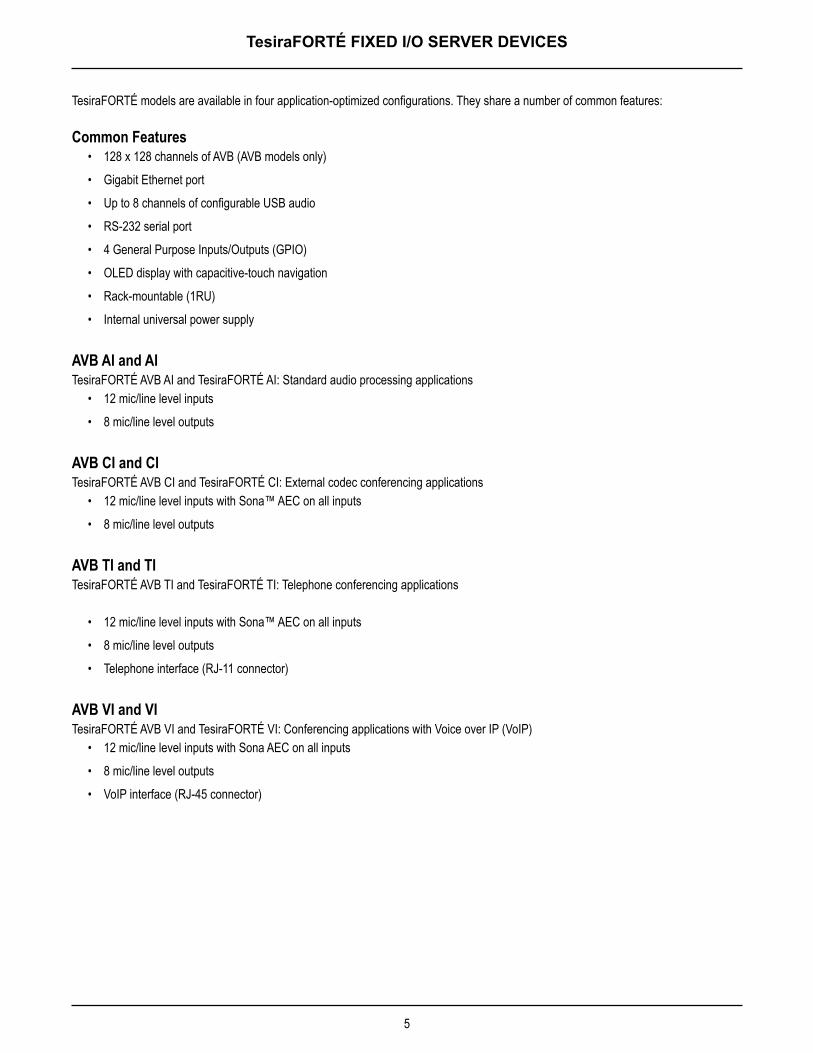
TesiraFORTÉ models are available in four application-optimized configurations. They share a number of common features:
Common Features• 128 x 128 channels of AVB (AVB models only)
• Gigabit Ethernet port
• Up to 8 channels of configurable USB audio
• RS-232 serial port
• 4 General Purpose Inputs/Outputs (GPIO)
• OLED display with capacitive-touch navigation
• Rack-mountable (1RU)
• Internal universal power supply
AVB AI and AITesiraFORTÉ AVB AI and TesiraFORTÉ AI: Standard audio processing applications
• 12 mic/line level inputs
• 8 mic/line level outputs
AVB CI and CITesiraFORTÉ AVB CI and TesiraFORTÉ CI: External codec conferencing applications
• 12 mic/line level inputs with Sona™ AEC on all inputs
• 8 mic/line level outputs
AVB TI and TITesiraFORTÉ AVB TI and TesiraFORTÉ TI: Telephone conferencing applications
• 12 mic/line level inputs with Sona™ AEC on all inputs
• 8 mic/line level outputs
• Telephone interface (RJ-11 connector)
AVB VI and VITesiraFORTÉ AVB VI and TesiraFORTÉ VI: Conferencing applications with Voice over IP (VoIP)
• 12 mic/line level inputs with Sona AEC on all inputs
• 8 mic/line level outputs
• VoIP interface (RJ-45 connector)
6
TesiraFORTÉ FIXED I/O SERVER DEVICES FRONT PANEL
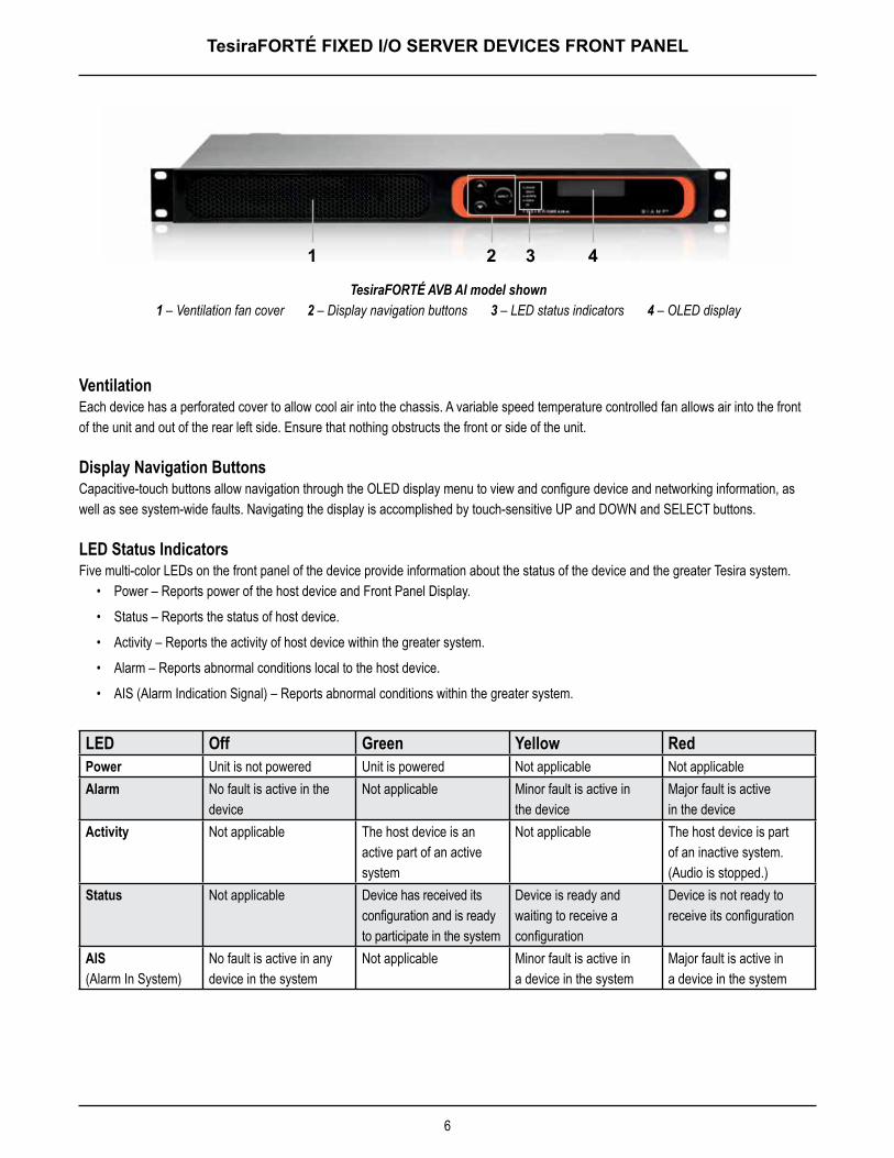
Ventilation Each device has a perforated cover to allow cool air into the chassis. A variable speed temperature controlled fan allows air into the front of the unit and out of the rear left side. Ensure that nothing obstructs the front or side of the unit.
Display Navigation ButtonsCapacitive-touch buttons allow navigation through the OLED display menu to view and configure device and networking information, as well as see system-wide faults. Navigating the display is accomplished by touch-sensitive UP and DOWN and SELECT buttons.
LED Status Indicators Five multi-color LEDs on the front panel of the device provide information about the status of the device and the greater Tesira system.
• Power – Reports power of the host device and Front Panel Display.
• Status – Reports the status of host device.
• Activity – Reports the activity of host device within the greater system.
• Alarm – Reports abnormal conditions local to the host device.
• AIS (Alarm Indication Signal) – Reports abnormal conditions within the greater system.
LED Off Green Yellow Red Power Unit is not powered Unit is powered Not applicable Not applicableAlarm No fault is active in the
device Not applicable Minor fault is active in
the deviceMajor fault is active in the device
Activity Not applicable The host device is an active part of an active system
Not applicable The host device is part of an inactive system. (Audio is stopped.)
Status Not applicable Device has received its configuration and is ready to participate in the system
Device is ready and waiting to receive a configuration
Device is not ready to receive its configuration
AIS (Alarm In System)
No fault is active in any device in the system
Not applicable Minor fault is active in a device in the system
Major fault is active in a device in the system
TesiraFORTÉ AVB AI model shown 1 – Ventilation fan cover 2 – Display navigation buttons 3 – LED status indicators 4 – OLED display
1 2 3 4
7
TesiraFORTÉ FIXED I/O SERVER DEVICES FRONT PANEL
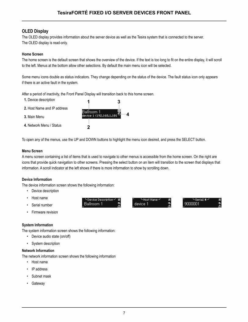
OLED DisplayThe OLED display provides information about the server device as well as the Tesira system that is connected to the server. The OLED display is read-only.
Home ScreenThe home screen is the default screen that shows the overview of the device. If the text is too long to fit on the entire display, it will scroll to the left. Menus at the bottom allow other selections. By default the main menu icon will be selected.
Some menu icons double as status indicators. They change depending on the status of the device. The fault status icon only appears if there is an active fault in the system.
After a period of inactivity, the Front Panel Display will transition back to this home screen.1. Device description
2. Host Name and IP address
3. Main Menu
4. Network Menu / Status
To open any of the menus, use the UP and DOWN buttons to highlight the menu icon desired, and press the SELECT button.
Menu ScreenA menu screen containing a list of items that is used to navigate to other menus is accessible from the home screen. On the right are icons that provide quick navigation to other screens. Pressing the select button on an item will transition to the screen that displays that information. A scroll indicator at the left shows if there is more information to show by scrolling down.
Device InformationThe device information screen shows the following information:
• Device description
• Host name
• Serial number
• Firmware revision
System InformationThe system information screen shows the following information:
• Device audio state (on/off)
• System description
Network InformationThe network information screen shows the following information
• Host name
• IP address
• Subnet mask
• Gateway
1 3
4
2
8
TesiraFORTÉ FIXED I/O SERVER DEVICES FRONT PANEL
SettingsThe setting operations include the following:- Change brightness- Change timeouts
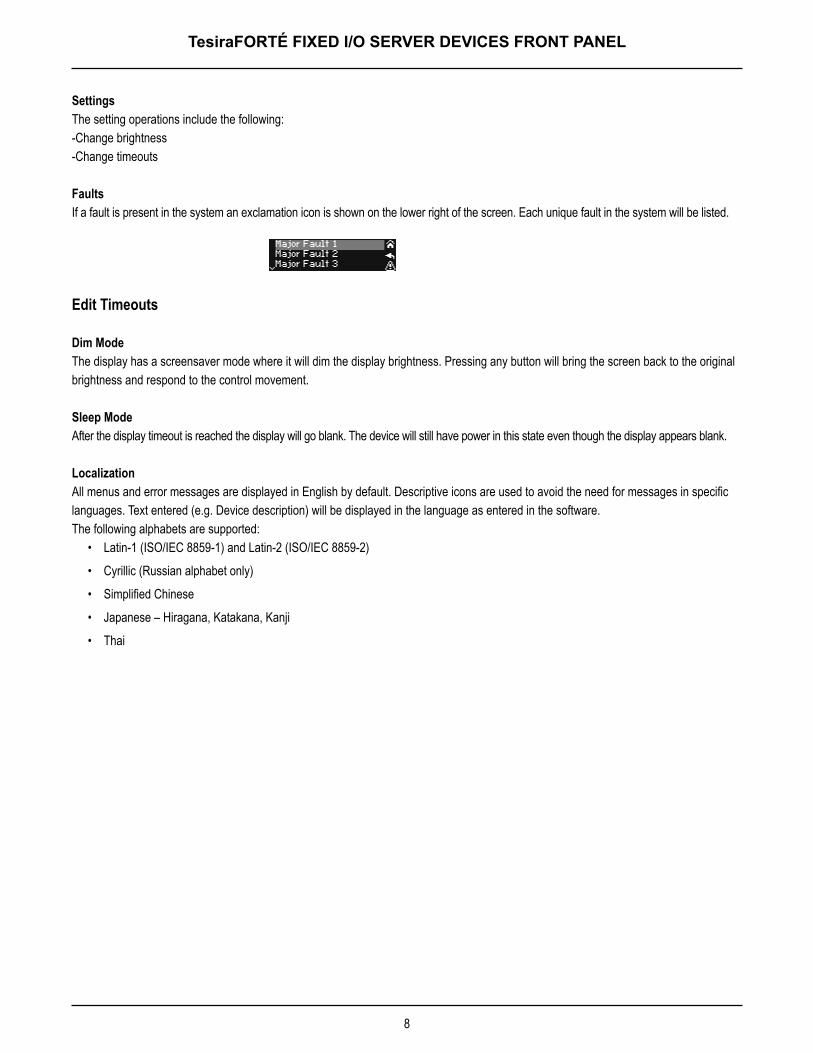
FaultsIf a fault is present in the system an exclamation icon is shown on the lower right of the screen. Each unique fault in the system will be listed.
Edit Timeouts
Dim ModeThe display has a screensaver mode where it will dim the display brightness. Pressing any button will bring the screen back to the original brightness and respond to the control movement.
Sleep ModeAfter the display timeout is reached the display will go blank. The device will still have power in this state even though the display appears blank.
LocalizationAll menus and error messages are displayed in English by default. Descriptive icons are used to avoid the need for messages in specific languages. Text entered (e.g. Device description) will be displayed in the language as entered in the software.The following alphabets are supported:
• Latin-1 (ISO/IEC 8859-1) and Latin-2 (ISO/IEC 8859-2)
• Cyrillic (Russian alphabet only)
• Simplified Chinese
• Japanese – Hiragana, Katakana, Kanji
• Thai
9
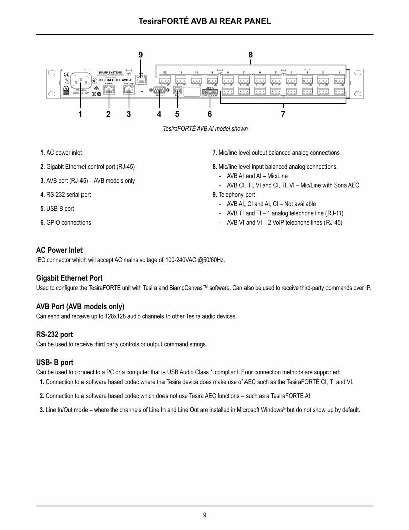
TesiraFORTÉ AVB AI REAR PANEL
AC Power InletIEC connector which will accept AC mains voltage of 100-240VAC @50/60Hz.
Gigabit Ethernet PortUsed to configure the TesiraFORTÉ unit with Tesira and BiampCanvas™ software. Can also be used to receive third-party commands over IP.
AVB Port (AVB models only)Can send and receive up to 128x128 audio channels to other Tesira audio devices.
RS-232 portCan be used to receive third party controls or output command strings.
USB- B portCan be used to connect to a PC or a computer that is USB Audio Class 1 compliant. Four connection methods are supported:
1. Connection to a software based codec where the Tesira device does make use of AEC such as the TesiraFORTÉ CI, TI and VI.
2. Connection to a software based codec which does not use Tesira AEC functions – such as a TesiraFORTÉ AI.
3. Line In/Out mode – where the channels of Line In and Line Out are installed in Microsoft Windows® but do not show up by default.
TesiraFORTÉ AVB AI model shown
1 2 3 4 5 6 7
89
1. AC power inlet
2. Gigabit Ethernet control port (RJ-45)
3. AVB port (RJ-45) – AVB models only
4. RS-232 serial port
5. USB-B port
6. GPIO connections
7. Mic/line level output balanced analog connections
8. Mic/line level input balanced analog connections. - AVB AI and AI – Mic/Line - AVB CI, TI, VI and CI, TI, VI – Mic/Line with Sona AEC
9. Telephony port - AVB AI, CI and AI, CI – Not available - AVB TI and TI – 1 analog telephone line (RJ-11) - AVB VI and VI – 2 VoIP telephone lines (RJ-45)
10
TesiraFORTÉ FIXED I/O SERVER DEVICES QUICK START
PrerequisitesBefore getting started please
1. Install Tesira software on a Windows PC. The software must be Tesira version 2.0 or later. The most up to date version can be downloaded from the Biamp website here: http://www.biamp.com/products/tesira/downloads.aspx.
2. Minimum PC requirements: a. Windows® 7 SP1 32-bit or 64-bitb. 1280 x 1024 screen resolution (recommended)
3. Cables required: Connection to the device should be made using either a direct connection or connection via an Ethernet switch. - Direct Connection - 1x Cat5E cable to connect from the PC to the TesiraFORTÉ Control Port - Via a Switch - 2x Cat5E cables and 1 Ethernet switch
Connecting to the TesiraFORTÉ system1. Connect the PC and TesiraFORTÉ to the network.
Connect a Cat5E cable between your PC and the TesiraFORTÉ device. - Direct connection: Attach an Ethernet cable from the PC’s network card to the TesiraFORTÉ Ethernet port. The TesiraFORTÉ
Ethernet port is autosensing so a straight or crossover cable can be used. - Connecting via Ethernet switch: Attach an Ethernet cable from the network card to a 100/1000 Base-T Ethernet switch.
The TesiraFORTÉ Ethernet port is autosensing so a straight or crossover cable can be used.
2. Power up TesiraFORTÉ devices: Connect the supplied power cord to a grounded AC mains voltage of 100-240VAC @50/60Hz. Connect the other end of the power cord to the power entrance located on the rear of the TesiraFORTÉ unit. Note the status of the front panel LED’s. Under normal conditions, the power, Activity and Status LEDS’s will remain green once power-up sequence has completed.
3. Assign an IP address to the PC. The PC must have a unique IP address in the same subnet as the TesiraFORTÉ device. A TesiraFORTÉ device is configured from the factory with DHCP or Zero Conf (Link Local) address. If you wish to verify your PC network interface is set correctly, please review the Setting an IP address section.
4. Configure the software to use the correct Network Interface. Tesira software should automatically discover the available network interfaces and enable them. If you wish to verify the network interfaces you are using, open the Tesira software and select Tools > Options > Application settings > Network > Device Discovery. Selecting Interfaces will list the available connections. These can be enabled or disabled individually. Confirm the expected Network interface is selected and IP addressing is in the correct range.
5. Connect to the network with Tesira software. Open the Tesira software. Connect to the network by going to System > Network > Connect to System. The System Connect dialog will appear. Select the required device listed in the System List and press Connect to System.
The software will connect and allow real time user control. When the required changes have been made, disconnect the PC from the Tesira system by going to System > Network > Disconnect from system.
11
TesiraFORTÉ FIXED I/O SERVER DEVICES QUICK START
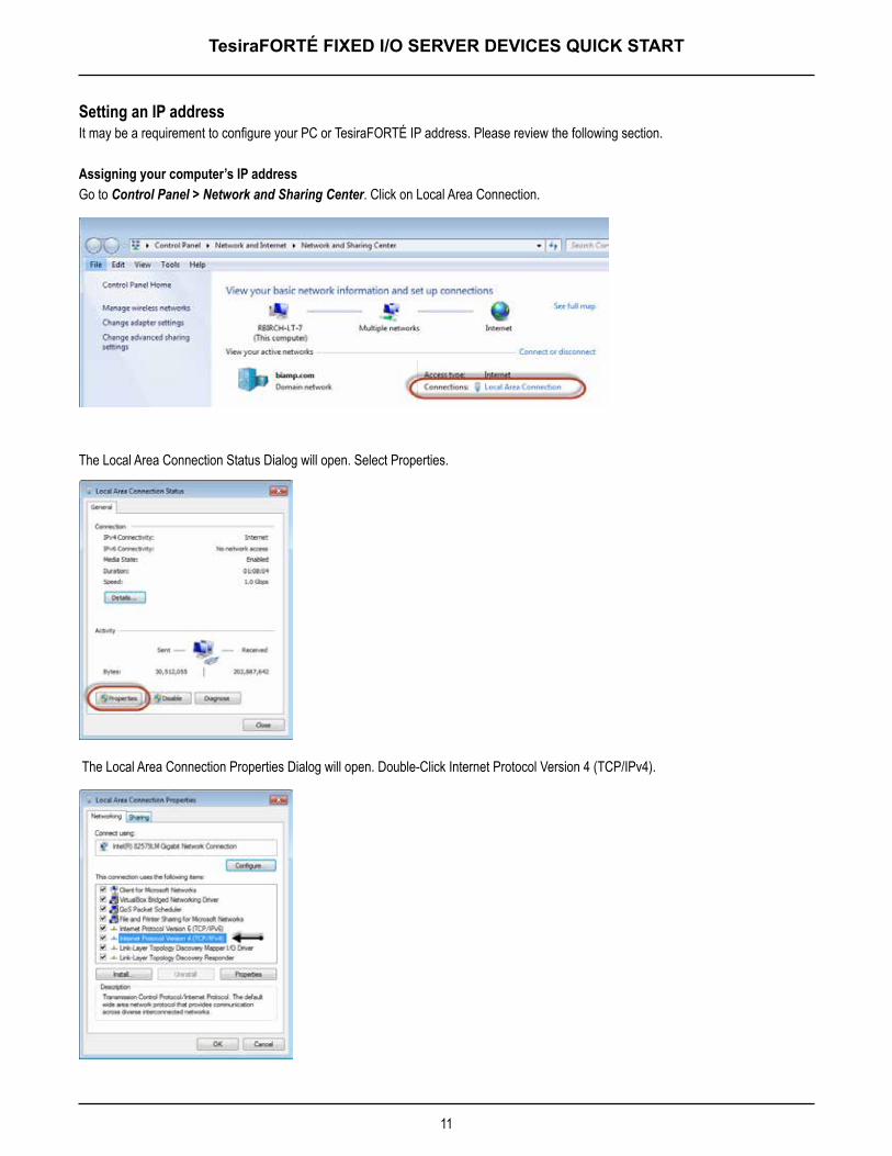
Setting an IP address It may be a requirement to configure your PC or TesiraFORTÉ IP address. Please review the following section.
Assigning your computer’s IP addressGo to Control Panel > Network and Sharing Center. Click on Local Area Connection.
The Local Area Connection Status Dialog will open. Select Properties.
The Local Area Connection Properties Dialog will open. Double-Click Internet Protocol Version 4 (TCP/IPv4).
12
TesiraFORTÉ FIXED I/O SERVER DEVICES QUICK START
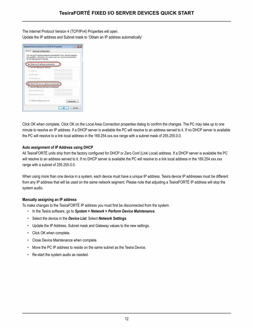
The Internet Protocol Version 4 (TCP/IPv4) Properties will open. Update the IP address and Subnet mask to ‘Obtain an IP address automatically’
Click OK when complete. Click OK on the Local Area Connection properties dialog to confirm the changes. The PC may take up to one minute to resolve an IP address. If a DHCP server is available the PC will resolve to an address served to it. If no DHCP server is available the PC will resolve to a link local address in the 169.254.xxx.xxx range with a subnet mask of 255.255.0.0.
Auto assignment of IP Address using DHCPAll TesiraFORTÉ units ship from the factory configured for DHCP or Zero Conf (Link Local) address. If a DHCP server is available the PC will resolve to an address served to it. If no DHCP server is available the PC will resolve to a link local address in the 169.254.xxx.xxx range with a subnet of 255.255.0.0.
When using more than one device in a system, each device must have a unique IP address. Tesira device IP addresses must be different from any IP address that will be used on the same network segment. Please note that adjusting a TesiraFORTÉ IP address will stop the system audio.
Manually assigning an IP addressTo make changes to the TesiraFORTÉ IP address you must first be disconnected from the system.
• In the Tesira software, go to System > Network > Perform Device Maintenance.
• Select the device in the Device List. Select Network Settings.
• Update the IP Address, Subnet mask and Gateway values to the new settings.
• Click OK when complete.
• Close Device Maintenance when complete.
• Move the PC IP address to reside on the same subnet as the Tesira Device.
• Re-start the system audio as needed.
13
TesiraFORTÉ FIXED I/O SERVER DEVICES SPECIFICATIONS
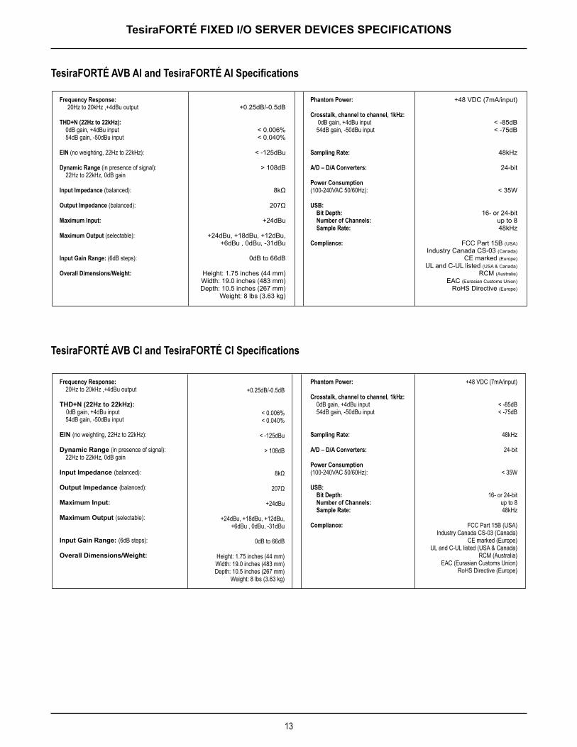
TesiraFORTÉ AVB AI and TesiraFORTÉ AI Specifications
TesiraFORTÉ AVB CI and TesiraFORTÉ CI Specifications
Frequency Response: 20Hz to 20kHz ,+4dBu output
THD+N (22Hz to 22kHz): 0dB gain, +4dBu input 54dB gain, -50dBu input
EIN (no weighting, 22Hz to 22kHz):
Dynamic Range (in presence of signal): 22Hz to 22kHz, 0dB gain
Input Impedance (balanced):
Output Impedance (balanced):
Maximum Input:
Maximum Output (selectable):
Input Gain Range: (6dB steps):
Overall Dimensions/Weight:
Phantom Power:
Crosstalk, channel to channel, 1kHz: 0dB gain, +4dBu input 54dB gain, -50dBu input
Sampling Rate:
A/D – D/A Converters:
Power Consumption(100-240VAC 50/60Hz):
USB: Bit Depth: Number of Channels: Sample Rate:
Compliance:
+0.25dB/-0.5dB
< 0.006%< 0.040%
< -125dBu
> 108dB
8kΩ
207Ω
+24dBu
+24dBu, +18dBu, +12dBu, +6dBu , 0dBu, -31dBu
0dB to 66dB
Height: 1 .75 inches (44 mm)Width: 19.0 inches (483 mm)Depth: 10.5 inches (267 mm)
Weight: 8 lbs (3.63 kg)
+48 VDC (7mA/input)
< -85dB< -75dB
48kHz
24-bit
< 35W
16- or 24-bitup to 848kHz
FCC Part 15B (USA)Industry Canada CS-03 (Canada)
CE marked (Europe)UL and C-UL listed (USA & Canada)
RCM (Australia)EAC (Eurasian Customs Union)
RoHS Directive (Europe)
Frequency Response: 20Hz to 20kHz ,+4dBu output
THD+N (22Hz to 22kHz): 0dB gain, +4dBu input 54dB gain, -50dBu input
EIN (no weighting, 22Hz to 22kHz):
Dynamic Range (in presence of signal): 22Hz to 22kHz, 0dB gain
Input Impedance (balanced):
Output Impedance (balanced):
Maximum Input:
Maximum Output (selectable):
Input Gain Range: (6dB steps):
Overall Dimensions/Weight:
Phantom Power:
Crosstalk, channel to channel, 1kHz: 0dB gain, +4dBu input 54dB gain, -50dBu input
Sampling Rate:
A/D – D/A Converters:
Power Consumption(100-240VAC 50/60Hz):
USB: Bit Depth: Number of Channels: Sample Rate:
Compliance:
+0.25dB/-0.5dB
< 0.006%< 0.040%
< -125dBu
> 108dB
8kΩ
207Ω
+24dBu
+24dBu, +18dBu, +12dBu, +6dBu , 0dBu, -31dBu
0dB to 66dB
Height: 1.75 inches (44 mm)Width: 19.0 inches (483 mm)Depth: 10.5 inches (267 mm)
Weight: 8 lbs (3.63 kg)
+48 VDC (7mA/input)
< -85dB< -75dB
48kHz
24-bit
< 35W
16- or 24-bitup to 848kHz
FCC Part 15B (USA)Industry Canada CS-03 (Canada)
CE marked (Europe)UL and C-UL listed (USA & Canada)
RCM (Australia)EAC (Eurasian Customs Union)
RoHS Directive (Europe)
14
TesiraFORTÉ FIXED I/O SERVER DEVICES SPECIFICATIONS
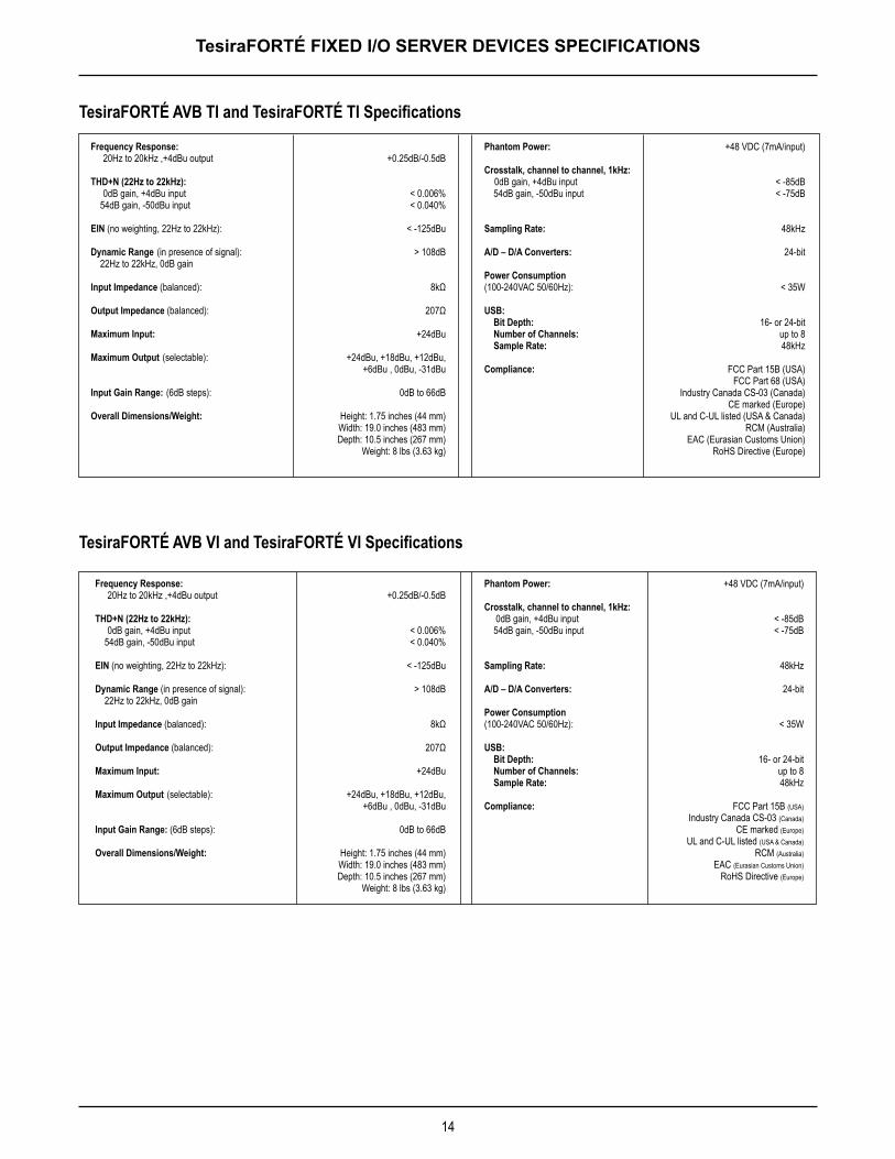
TesiraFORTÉ AVB TI and TesiraFORTÉ TI Specifications
TesiraFORTÉ AVB VI and TesiraFORTÉ VI Specifications
Frequency Response: 20Hz to 20kHz ,+4dBu output
THD+N (22Hz to 22kHz): 0dB gain, +4dBu input 54dB gain, -50dBu input
EIN (no weighting, 22Hz to 22kHz):
Dynamic Range (in presence of signal): 22Hz to 22kHz, 0dB gain
Input Impedance (balanced):
Output Impedance (balanced):
Maximum Input:
Maximum Output (selectable):
Input Gain Range: (6dB steps):
Overall Dimensions/Weight:
Phantom Power:
Crosstalk, channel to channel, 1kHz: 0dB gain, +4dBu input 54dB gain, -50dBu input
Sampling Rate:
A/D – D/A Converters:
Power Consumption(100-240VAC 50/60Hz):
USB: Bit Depth: Number of Channels: Sample Rate:
Compliance:
+0.25dB/-0.5dB
< 0.006%< 0.040%
< -125dBu
> 108dB
8kΩ
207Ω
+24dBu
+24dBu, +18dBu, +12dBu, +6dBu , 0dBu, -31dBu
0dB to 66dB
Height: 1.75 inches (44 mm)Width: 19.0 inches (483 mm)Depth: 10.5 inches (267 mm)
Weight: 8 lbs (3.63 kg)
+48 VDC (7mA/input)
< -85dB< -75dB
48kHz
24-bit
< 35W
16- or 24-bitup to 848kHz
FCC Part 15B (USA)FCC Part 68 (USA)
Industry Canada CS-03 (Canada)CE marked (Europe)
UL and C-UL listed (USA & Canada)RCM (Australia)
EAC (Eurasian Customs Union)RoHS Directive (Europe)
Frequency Response: 20Hz to 20kHz ,+4dBu output
THD+N (22Hz to 22kHz): 0dB gain, +4dBu input 54dB gain, -50dBu input
EIN (no weighting, 22Hz to 22kHz):
Dynamic Range (in presence of signal): 22Hz to 22kHz, 0dB gain
Input Impedance (balanced):
Output Impedance (balanced):
Maximum Input:
Maximum Output (selectable):
Input Gain Range: (6dB steps):
Overall Dimensions/Weight:
Phantom Power:
Crosstalk, channel to channel, 1kHz: 0dB gain, +4dBu input 54dB gain, -50dBu input
Sampling Rate:
A/D – D/A Converters:
Power Consumption(100-240VAC 50/60Hz):
USB: Bit Depth: Number of Channels: Sample Rate:
Compliance:
+0.25dB/-0.5dB
< 0.006%< 0.040%
< -125dBu
> 108dB
8kΩ
207Ω
+24dBu
+24dBu, +18dBu, +12dBu, +6dBu , 0dBu, -31dBu
0dB to 66dB
Height: 1.75 inches (44 mm)Width: 19.0 inches (483 mm)Depth: 10.5 inches (267 mm)
Weight: 8 lbs (3.63 kg)
+48 VDC (7mA/input)
< -85dB< -75dB
48kHz
24-bit
< 35W
16- or 24-bitup to 848kHz
FCC Part 15B (USA)Industry Canada CS-03 (Canada)
CE marked (Europe)UL and C-UL listed (USA & Canada)
RCM (Australia)EAC (Eurasian Customs Union)
RoHS Directive (Europe)
151515
BIAMP SYSTEMS IS PLEASED TO EXTEND THE FOLLOWING 5-YEAR LIMITED WARRANTY TO THE ORIGINAL PURCHASER OF THE PROFESSIONAL SOUND EQUIPMENT DESCRIBED IN THIS MANUAL
1. Biamp Systems warrants to the original purchaser of new products that the product will be free from defects in material and workman-ship for a period of 5 YEARS from the date of purchase from an authorized Biamp Systems dealer, subject to the terms and conditions set forth below.
2. If you notify Biamp Systems during the warranty period that a Biamp Systems product fails to comply with the warranty, Biamp Systems will repair or replace, at Biamp Systems’ option, the nonconforming product. As a condition to receiving the benefits of this warranty, you must provide Biamp Systems with documentation that establishes that you were the original purchaser of the products. Such evidence may consist of your sales receipt from an authorized Biamp Systems dealer. Transportation and insurance charges to and from the Biamp Systems factory for warranty service shall be your responsibility.
3. This warranty will be VOID if the serial number has been removed or defaced; or if the product has been altered, subjected to damage, abuse or rental usage, repaired by any person not authorized by Biamp Systems to make repairs; or installed in any manner that does not comply with Biamp Systems’ recommendations.
4. Electro-mechanical fans, electrolytic capacitors, gooseneck microphones, cords connecting handheld microphones, hard-drives, displays, and normal wear and tear of items such as paint, knobs, handles, keypads and covers are not covered under this warranty. All server-based devices are warranted for 3 years only.
5. This warranty is in lieu of all other warranties, expressed or implied. Biamp Systems disclaims all other warranties, expressed or implied, including, but not limited to, implied warranties of merchantability and fitness for a particular purpose.
6. The remedies set forth herein shall be the purchaser’s sole and exclusive remedies with respect to any defective product.
7. No agent, employee, distributor or dealer of Biamp Systems is authorized to modify this warranty or to make additional warranties on behalf of Biamp Systems. Statements, representations or warranties made by any dealer do not constitute warranties by Biamp Systems. Biamp Systems shall not be responsible or liable for any statement, representation or warranty made by any dealer or other person.
8. No action for breach of this warranty may be commenced more than one year after the expiration of this warranty.
9. Biamp Systems shall not be liable for special, indirect, incidental, or consequential damages, including lost profits or loss of use arising out of the purchase, sale, or use of the products, even if Biamp Systems was advised of the possibility of such damages.
WARRANTY
585.0393.90A
161616
FCC COMPLIANCE FCC Notice - Class A digital device - This equipment has been tested and found to comply with the limits for a Class A digital device, pursuant to Part 15 of the FCC Rules. These limits are designed to provide reasonable protection against harmful interference when the equipment is operated in a commercial environment. This equipment generates, uses, and can radiate radio frequency energy and, if not installed and used in accordance with the instruction manual, may cause harmful interference to radio communications. Operation of this equipment in a residential area is likely to cause harmful interference in which case the user will be required to correct the interference at own expense.
TELECOM COMPLIANCECAUTION – For protection against overvoltage on telecommunication circuits, for example from power line crosses; use minimum No. 26 AWG telecommunication line cord.
Telephone Interface Information - This equipment complies with Part 68 of the FCC rules and the requirements adopted by the ACTA. On the rear panel of this equipment are markings that contain, among other information, telecom product identifier US:6RMBR00BSTC-2. If requested, this number must be provided to the telephone company.
This equipment is designed for modular connection with Universal Service Order Codes (USOC) RJ-11C, RJ-11W, RJ-14C, RJ-14W.
A plug and jack used to connect this equipment to the premises wiring and telephone network must comply with the applicable FCC Part 68 rules and requirements adopted by the ACTA. A compliant telephone cord and modular plug is provided with this product. It is designed to be connected to a compatible modular jack that is also compliant. See installation instructions for details.
Ringer Equivalency Number (REN) - The REN is used to determine the number of devices that may be connected to a telephone line. Excessive RENs on a telephone line may result in the devices not ringing in response to an incoming call. In most but not all areas, the sum of RENs should not exceed five (5.0). To be certain of the number of devices that may be connected to a line, as determined by the total RENs, contact the local telephone company. The REN for this product is 0.0 as indicated by part of the product identifier that has the format US:AAAEQ##TXXXX. The digits represented by ## are the REN without a decimal point (e.g., 00 is a REN of 0.0).
Alarms connected to telephone line - If your facility has specially wired alarm equipment connected to the telephone line, ensure the installation of this US:6RMBR00BSTC-2 does not disable your alarm equipment. If you have questions about what will disable alarm equipment, consult your telephone company or a qualified installer.
Automatic Dialer - WHEN PROGRAMMING EMERGENCY NUMBERS AND (OR) MAKING TEST CALLS TO EMERGENCY NUMBERS:1. Remain on the line and briefly explain to the dispatcher the reason for the call.2. Perform such activities in the off-peak hours, such as early morning or late evenings.
Electrical Safety Advisory - Telephone companies report that electrical surges, typically lightning transients, are very destructive to customer terminal equipment connected to AC power sources. The use of a surge arrestor on the telephone line is recommended, particularly in areas that are prone to lightning strikes.
Service - This equipment is not user serviceable. If trouble is experienced with this equipment US:6RMBR00BSTC-2, for repair or warranty information, please contact Biamp Systems Corporation, phone number 503.641.7287. If the equipment is causing harm to the telephone network, the telephone company may request that you disconnect the equipment until the problem is resolved.
If this equipment US:6RMBR00BSTC-2 causes harm to the telephone network, the telephone company will notify you in advance that temporary discontinuance of service may be required. But if advance notice isn’t practical, the telephone company will notify the customer as soon as possible. Also, you will be advised of your right to file a complaint with the FCC if you believe it is necessary.
COMPLIANCE
171717
COMPLIANCE
The telephone company may make changes in its facilities, equipment, operations or procedures that could affect the operation of the equipment. If this happens, the telephone company will provide advance notice in order for you to make necessary modifications to maintain uninterrupted service.
Party Lines - Connection to party line service is subject to state tariffs. Contact the state public utility commission, public service commission or corporation commission for information.
New Zealand Telecom NoticeNew Zealand Telepermit - The grant of a Telepermit for any item of terminal equipment indicates only that Telecom has accepted that the item complies with minimum conditions for connection to its network. It indicates no endorsement of the product by Telecom, nor does it provide any sort of warranty. Above all, it provides no assurance that any item will work correctly in all respects with another item of Telepermitted equipment of a different make or model, nor does it imply that any product is compatible with all of Telecom’s network services
This equipment shall not be set up to make automatic calls to the Telecom ‘111’ Emergency Service
IMPORTANT NOTICE - Under power failure conditions, this telephone may not operate. Please ensure that a separate telephone, not dependent on local power, is available for emergency use.

18
COMPLIANCE
19
COMPLIANCE
2020
INSTRUCCIONES DE SEGURIDAD IMPORTANTES
Rayo: Voltajes activos peligrosos mientras la unidad está en funcionamiento. No toque las terminales marcadas con este símbolo mientras la unidad se encuentre conectada a una salida activa de energía .Signo de exclamación: Reemplace los componentes (es decir, los fusibles) solo de acuerdo con los valores indicados por el fabricante. De no hacerlo, se pondrá en riesgo el funcionamiento seguro de esta unidad.Aspas de ventilador en movimiento peligrosas Desenchufe el producto antes de realizar reparaciones y aléjelo de las aspas en movimiento de los ventiladores .
Explicación de los símbolos gráficos:
1) Lea estas instrucciones .2) Guarde estas instrucciones .3) Preste atención a todas las advertencias.4) Siga todas las instrucciones .5) No utilice este producto cerca del agua .6) Limpie solo con un paño seco.7) No obstruya los orificios de ventilación. Instale el producto según las instrucciones del fabricante .8) No lo instale cerca de ninguna fuente de calor como radiadores, rejillas de calefacción, estufas u otros productos (incluidos amplificadores) que produzcan calor .9) No anule el propósito de seguridad del enchufe con conexión a tierra. Un enchufe con conexión a tierra tiene dos clavijas y una tercera punta con conexión a tierra . La tercera punta se provee para su seguridad . Si el enchufe suministrado no se adapta a su tomacorriente, recurra a un electricista para reemplazar la toma obsoleta .10) Proteja el cable de alimentación eléctrica para evitar que sea pisado o aplastado, en especial en los enchufes, receptáculos convenientes y el punto donde salen del producto .
11) Solo utilice complementos/accesorios indicados por el fabricante .12) Utilice solo con el soporte, carro, base o mesa diseñados para proporcionar fuerza mecánica adecuada, disipación del calor y seguridad a la estructura del edificio. Cuando se utiliza un carro, tenga cuidado al mover la combinación del carro con el producto para evitar lesiones en caso de una caída .13) Desenchufe este producto durante tormentas eléctricas o si no va a utilizarlo por largos períodos de tiempo .14) Todas las reparaciones deben ser realizadas por personal calificado. La reparación es necesaria cuando el producto presenta cualquier tipo de daño como, por ejemplo, si se deteriora el cable de alimentación eléctrica o enchufe, si se derraman líquidos o caen objetos dentro del producto, si se expone el producto a la lluvia o humedad, si no funciona normalmente o si se ha caído .
2121
INSTRUCCIONES DE SEGURIDAD IMPORTANTES
ADVERTENCIA – Para reducir el riesgo de incendio o descarga eléctrica, no exponga estos productos a la lluvia o humedad. Estos productos no deben exponerse a goteos o salpicaduras ni deben posarse sobre ellos objetos que contengan líquidos como, por ejemplo, jarrones.
ADVERTENCIA – Las terminales de altavoces de 100 voltios que aparecen marcadas con el símbolo están activas y son peligrosas. La conexión externa de cables a estas terminales requiere la instalación a cargo de una persona calificada o debidamente instruida .
ADVERTENCIA – Los productos con alimentación eléctrica utilizan conexión a tierra de seguridad y deben conectarse a tomacorrientes que funcionen correctamente para brindar una conexión a tierra de protección.
Desconexión del dispositivo – El enchufe de alimentación eléctrica se utiliza para desconectar esta alimentación y deberá poder accionarse fácilmente .
PRECAUCIÓN – Cuando se proporcionan las opciones de interfaz telefónica POTS, las conexiones a los circuitos de telecomunicaciones de este dispositivo deber ser realizadas por personal calificado y entrenado. Para reducir el riesgo de incendio, use solo cables de cobre sólido N.° 26 AWG para las conexiones de los circuitos de telecomunicaciones.
Para la instalación y mantenimiento solo por parte de personal calificado:PRECAUCIÓN – Para reducir el riesgo de descarga eléctrica, la instalación y el mantenimiento de los productos Biamp deben ser realizados por personas calificados que formen parte de los Profesionales capacitados en la instalación de audio de Biamp .
No realice ninguna reparación que no se encuentre en las Instrucciones de uso, a menos que sea una persona calificada para hacerlo .
Las personas calificadas deben desenchufar la alimentación eléctrica de CA antes de abrir el producto.
PRECAUCIÓN – Los pasos para la instalación de una “energía auxiliar” están dirigidos solo al personal calificado y deben cumplir con todos los códigos locales .
• Código eléctrico nacional: ANSI/NFPA 70 para los Estados Unidos.
• Código eléctrico canadiense: parte 1, CSA C22.1, secciones 2-128, 12-010(3) y 12-100 para Canadá.
Instrucciones para el montaje sobre la pared – Los productos que sean montados sobre la pared deben estar bien ajustados al yeso u otra superficie con el uso de, al menos, 4 tornillos para madera (2 tornillos para los productos con solo dos orificios de montaje). Los enganches alternativos que pueden utilizarse incluyen pernos de anclaje para paredes de yeso, tornillos de metal laminado con rosca cortante los cuales se ubican en montantes de metal o tornillos para madera que se prolongan poco más de 1,5 cm dentro de los montantes de madera.
2222
CONSIGNES DE SÉCURITÉ IMPORTANTES
Éclair : tensions dangereuses présentes lorsque l’appareil est en fonctionnement. Ne touchez pas les parties de l’appareil portant ce pictogramme tant qu’il est branché sur une ligne électrique.Point d’exclamation : remplacez les composants (fusibles, par exemple) uniquement par des composants possédant les caractéristiques spécifiées par le fabricant sous peine d’altérer le bon fonctionnement de l’appareil.Danger : pales de ventilateur en mouvement . Coupez l’alimentation avant toute intervention et restez à distance des pales en mouvement .
Signification des pictogrammes:
1) Lisez attentivement les présentes instructions .2) Conservez les présentes instructions .3) Prêtez une extrême attention aux avertissements.4) Respectez toutes les consignes données .5) N’utilisez pas ce produit à proximité d’eau .6) Nettoyez uniquement avec un chiffon sec.7) Ne bouchez pas les ouvertures destinées à la ventilation . Suivez les instructions d’installation du fabricant .8) Tenez le produit à l’écart des sources de chaleur, comme les radiateurs, les grilles d’air chaud, les cuisinières ou autres produits (dont amplificateurs) qui émettent de la chaleur .9) Préservez la protection offerte par le branchement de mise à la terre . Le connecteur est reconnaissable par ses deux broches accompagnées d’un contact de mise à la terre . Ce troisième contact est fourni pour votre sécurité . Si le connecteur fourni ne correspond pas à votre prise, renseignez-vous auprès d’un électricien .10) Placez le cordon à l’écart des zones de passage et veillez à ce qu’il ne soit pas pincé, en particulier au niveau des prises, des multiprises et de la sortie de l’appareil .
11) Utilisez exclusivement les fixations/accessoires spécifiés par le fabricant.12) Utilisez uniquement des tables, supports, étagères ou chariots capables de supporter le poids du produit et d’offrir la dissipation de chaleur et la sécurité requises (fixation à la structure du bâtiment) . Si vous placez le produit sur un chariot, déplacez-le avec précaution pour éviter de le renverser .13) Débranchez le produit pendant les orages ou les périodes d’inutilisation prolongées .14) Confiez toutes les interventions à un personnel qualifié. Ces interventions peuvent s’avérer nécessaire dans certaines situations : détérioration du produit (connecteur ou cordon d’alimentation endommagé, par exemple), liquide renversé sur le produit, objets tombés dans le produit, exposition du produit à l’humidité ou à la pluie, fonctionnement anormal du produit, chute du produit, etc.
2323
CONSIGNES DE SÉCURITÉ IMPORTANTES
AVERTISSEMENT – Pour limiter les risques d’incendie ou d’électrocution, n’exposez pas ce produit à l’humidité ou à la pluie. Mettez-le à l’abri des projections et écoulements, et veillez à ne placer aucun objet rempli de liquide (vases, par exemple) à proximité .
AVERTISSEMENT – Les bornes des haut-parleurs 100 V comportent le pictogramme signalant une tension dangereuse . Toute connexion externe à ces bornes doit être effectuée par un technicien qualifié ou compétent.
AVERTISSEMENT – Le raccordement du produit au secteur doit être réalisé par le biais d’un câble et d’une prise offrant une mise à la terre adéquate.
Débranchement de l’appareil – La prise secteur doit être accessible pour que l’appareil puisse être débranché dès que l’utilisateur souhaite couper l’alimentation .
MISE EN GARDE – En présence d’un service téléphonique traditionnel, les connexions aux circuits de télécommunication de l’appareil doivent être effectuées par un personnel qualifié et compétent. Pour limiter les risques d’incendie, utilisez uniquement des fils de cuivre solides de calibre AWG 26 (0,129 mm2) .
Installation et interventions réservées au personnel compétent :MISE EN GARDE – Pour limiter les risques d’électrocution, l’installation des produits Biamp et les interventions sur ces produits doivent être réalisées uniquement par du personnel compétent faisant partie des professionnels d’installation audio qualifiés de Biamp.
Seul le personnel compétent est habilité à exécuter des opérations d’entretien ou de maintenance autres que celles indiquées dans les instructions d’utilisation .
Le personnel compétent doit débrancher l’alimentation secteur avant toute tentative d’accès à l’intérieur du produit .
MISE EN GARDE – Les instructions d’installation qui se rapportent à l’alimentation auxiliaire sont exclusivement destinées au personnel compétent. Cette installation doit être effectuée conformément aux réglementations locales.
• National Electrical Code, ANSI/NFPA 70 pour les États-Unis
• Canadian Electrical Code, partie 1, CSA C22.1, sections 2-128, 12-010(3) et 12-100 pour le Canada
Consignes pour le montage mural – Dans tout montage mural, le produit doit être solidement fixé à une cloison sèche ou autre surface similaire au moyen de quatre vis à bois au minimum (deux vis s’il s’agit d’un produit comportant uniquement deux trous de montage). D’autres fixations peuvent être utilisées, comme des chevilles pour cloison sèche, des vis à tôle en cas de poteau métallique ou des vis à bois s’enfonçant au moins sur 1,5 cm (0,5 po) dans la structure bois.
2424
WICHTIGE SICHERHEITSHINWEISE
Blitz: Beim Betrieb dieses Geräts entstehen lebensgefährliche Spannungen . Berühren Sie keine Anschlüsse mit diesem Symbol, während das Gerät an ein Netzteil mit eingeschalteter Spannungsversorgung angeschlossen ist.Ausrufezeichen: Ersetzen Sie Bauteile (z . B . Sicherungen) nur entsprechend den vom Hersteller angegebenen Werten . Bei Missachtung ist die Sicherheit dieses Geräts nicht mehr gewährleistet .Rotierende Lüfterflügel: Vor Wartungsarbeiten Stromversorgung unterbrechen und von beweglichen Lüfterflügeln fernhalten .
Erklärung grafischer Symbole:
1) Lesen Sie diese Hinweise .2) Bewahren Sie diese Hinweise auf .3) Beachten Sie die Warnhinweise.4) Befolgen Sie die Hinweise .5) Verwenden Sie dieses Produkt nicht in der Nähe von Wasser .6) Nur mit einem trockenen Tuch reinigen.7) Ventil- und Lüftungsöffnungen nicht abdecken . Produkte gemäß den Hinweisen des Herstellers installieren .8) Nicht in der Nähe von Wärmequellen wie Radiatoren, Wärmespeichern, Kochflächen oder sonstigen Produkten (einschließlich Verstärker), die Wärme produzieren, installieren.9) Sicherheitsfunktion des geerdeten Steckers nicht umgehen . Ein geerdeter Stecker hat zwei Stromkontakte und einen dritten Erdungskontakt . Der dritte Erdungskontakt dient Ihrer Sicherheit . Passt der mitgelieferte Stecker nicht in die Steckdose, lassen Sie diese von einem Elektriker austauschen .10) Schützen Sie das Netzkabel vor Beschädigungen, besonders am Stecker, an Mehrfachsteckdosen und am Ausgang vom Gerät .
11) Verwenden Sie ausschließlich die vom Hersteller angegebenen Befestigungen/Zubehörteile.12) Nur mit Geräteträger, Rollwagen, Ständer oder Tisch verwenden, wobei eine ausreichende mechanische Festigkeit, Wärmeableitung und Absicherung mit der Gebäudestruktur geboten ist . Wenn ein Rollwagen verwendet wird, beim Bewegen der Rollwagen-Gerät-Kombination vorsichtig vorgehen, um Verletzungen durch Umkippen zu vermeiden.13) Trennen Sie das Gerät während eines Gewitters oder bei längerer Nichtbenutzung vom Stromnetz .14) Überlassen Sie jegliche Wartung qualifiziertem Personal . Wartungsarbeiten oder Reparaturen sind erforderlich, wenn das Netzkabel oder der Stecker beschädigt ist, wenn Flüssigkeit oder Gegenstände in das Geräteinnere eingedrungen sind, wenn das Gerät im Regen oder in feuchter Umgebung gestanden ist, sich nicht erwartungsgemäß verhält oder wenn es gefallen ist .
2525
WICHTIGE SICHERHEITSHINWEISE
ACHTUNG – Um das Risiko eines Brandes oder eines elektrischen Schlages zu vermeiden, das Gerät vor Regen und Feuchtigkeit schützen. Das Gerät vor Tropfen oder Wasserspritzern schützen. Keine mit Flüssigkeit befüllten Behälter, wie Blumenvasen oder ähnliche Gegenstände, auf das Gerät stellen.
ACHTUNG – 100-Volt-Lautsprecherklemmen mit dem Symbol bedeuten Lebensgefahr . Die externe Verkabelung an diesen Anschlüssen darf nur von geschulten oder beaufsichtigten Personen vorgenommen werden .
ACHTUNG – An das Netzteil angeschlossene Geräte verfügen über eine Sicherheitserdung und müssen an eine ordnungsgemäß geerdete Buchse angeschlossen werden, um eine sichere Erdverbindung zu gewährleisten.
Trennen des Geräts – Der Netzstecker wird verwendet, um das Gerät von der Netzsteckdose zu trennen und muss jederzeit betriebsbereit sein .
VORSICHT – Wenn Telefonschnittstellenoptionen angeboten werden, sind die Verbindungen zum Netz des Telefonanbieters von einer qualifizierten und geschulten Person vorzunehmen. Verwenden Sie für Telekomverbindungen ausschließlich 26 AWG feste Kupferdrahtanschlüsse, um das Brandrisiko zu reduzieren.
Ausschließlich für Einbau und Wartung durch geschultes Personal vorgesehen:VORSICHT – Zur Verringerung der Stromschlaggefahr sind Einbau und Wartung von Biamp-Geräten ausschließlich durch geschulte Personen, bei denen es sich um von Biamp geschulte Audio-Fachleute handelt, vorzunehmen.
Führen Sie keine anderen als die in der Betriebsanleitung angegebenen Wartungsarbeiten aus, vorausgesetzt, Sie wurden hierfür geschult .
Vor dem Öffnen des Geräts ist das Gerät von einer geschulten Person von der AC-Netzspannung zu trennen .
VORSICHT – Die Installationsschritte für die Hilfsspannungsversorgung sind nur zur Verwendung durch geschulte Personen vorgesehen und müssen mit den örtlichen Bestimmungen übereinstimmen .
• National Electrical Code, ANSI/NFPA 70 für die USA.
• Canadian Electrical Code, Part 1, CSA C22.1, Kapitel 2-128, 12-010(3) und 12-100 für Kanada.
Anweisungen zur Wandmontage – Geräte zur Wandmontage sind mit mindestens 4 Holzschrauben sicher an einer Trockenbauwand oder an einer ähnlichen Oberfläche zu befestigen (2 Schrauben für Geräte mit nur zwei Befestigungsösen). Alternativ verwendete Befestigungselemente umfassen Dübel für Trockenwände, selbstschneidende Schrauben in Metallrohlingen oder Holzschrauben, die mindestens 1,5 cm in die Holzrohlinge eingedreht werden können.
2626
重要安全说明
闪电:此设备运行时会伴随有危险的实时电压。当设备与电源连接时,不要触碰带有此符号的端子。
惊叹号:只能按照厂商指定的技术参数更换组件(例如:保险丝)。 否则,将会降低本设备的运行安全性。
危险的移动风扇叶片:请在提供服务之前切断电源,并与移动风扇叶片保持距离。
图形符号解释:
1) 阅读这些说明。
2) 妥善保管这些说明。
3) 留意所有警告。
4) 遵守所有说明。
5) 不得在靠近水源处使用本产品。
6) 只能用干布进行清洁。
7) 不要堵塞通风口。按照厂商说明进行安装。
8) 不要在靠近任何热源处,如散热器、热调节器、火炉
或其他释放热量的产品(包括扩音器)附近进行安装。
9) 不要损坏用于安全目的的接地插头。 接地插头有两个
插片和第三端接地管脚。 第三端管脚是为了确保您的安全而提供。如果附带的插头
不适用于您的插座,请让电工更换插座。
10) 防止电源线被踩踏或挤压,尤其是在插头、电源插座
以及产品周围进出的位置。
11) 只使用厂商指定的附属装置/附件。
12) 只配合专为建筑结构提供足够的机
械强度、热消散性和稳固性的机柜、手推
车、支架或设备桌使用。 在用手推车时应小心移动,避免因翻倒而
带来伤害。
13) 在室外出现闪电或长期未使用的情况下应拔掉本产品
的电源线。
14) 请与有资历的服务人员联系,获得所有维修服务。
当产品以任何方式受到损害时有必要进行维修,如电源线
或插头被损坏、沾染上液体或有异物落入产品中、产品暴
露在雨水或潮湿的环境中、无法正常运行或已掉落在地上
损坏了。
2727
重要安全说明
警告 – 为减少火灾或雷电冲击带来的风险,不要将这些产品暴露在雨水或潮湿的环境中。这些产品不得暴露在有液体滴落或飞
溅的环境中,也不应在这些产品上放置装有液体的物品(如花瓶)。
警告 – 标有符号 的 100 伏特扬声器端子是危险的带电线路。与这些端子相连的外部布线需要由专业技术人员或经过培训的
人员来安装。
警告 – 由市电供电的产品采用了安全接地技术,必须与正确接地的市电插座连接,才能提供接地防护。
断开设备连接 – 市电插头可用于断开 市电电源且必须保持时刻可运行状态。
小心 – 在提供了 POTS 电话接口选项时,必须由训练有素的人员将电话接口与本设备的电信回路进行连接。为减少火灾风险,
只能使用 26 号 AWG 实心铜线连接电话端口。
只适用于专业技术人员来执行的安装和服务:
小心 – 为减少电击带来的风险,Biamp 产品的安装和服务应该只能由 Biamp 音频安装专业技术人员来执行。
除非您是专业技术人员,否则不能执行未包含在操作说明中的任何服务。
在打开产品之前,专业人员必须先断开交流市电电源。
小心 – “辅助电源”的安装步骤只适用于专业技术人员,而且必须遵循所有的本地法规。
• 对于美国,国家电气法规 ANSI/NFPA 70。
• 对于加拿大,加拿大电气法规第 1 部 CSA C22 .1 第 2-128、12-010(3) 和 12-100 节。
壁挂安装说明 – 壁挂安装产品必须至少使用 4 个木螺丝(只有两个安装孔的产品则用 2 个螺丝)安全地固定在石膏板/隔断墙或
类似表面上。可能会用到的其他紧固件包括胀管、用于金属支撑架中的自攻钢板金属螺丝或是用于木制支撑架上的 ½ 英寸木螺
丝。
2828
중요 안전성 지침
번개 표시: 본 장비가 작동 중일 때는 위험한 전압이 발생합니다. 본 장비가 전원에 연결되어 있는 동안에는 이
기호가 표시된 터미널에 손을 대지 마십시오 .느낌표: 구성 부품(예:퓨즈)은 제조업체에 의해 지정된 사양으로만 교환합니다. 그렇지 않으면 본 장비의 안전한
작동에 문제가 생길 수 있습니다 .위험한 이동식 송풍기 블레이드: 전원을 끄고 나서 서비스를 제공하고, 이동식 송풍기 블레이드를 가까이 두지
마십시오 .
그래픽 기호 설명:
1) 이 지침서를 읽으십시오 .2) 이 지침 내용을 지키십시오 .3) 모든 경고에 주의를 기울이십시오 .4) 모든 지침을 따르십시오 .5) 이 제품을 물 가까이에서 사용하지 마십시오 .6) 마른 헝겊으로만 닦으십시오 .7) 환풍구를 막지 마십시오. 제조업체의 지침에 따라
설치하십시오 .8) 라디에이터, 온풍기, 스토브 또는 열을 내는 다른
제품(증폭기 포함)과 같은 열원 근처에 설치하지
마십시오 .9) 접지형 플러그의 안전 목적에 어긋나지 않도록
하십시오. 접지형 플러그에는 두 개의 날과 접지 단자가
있습니다 . 세 번째 접지 단자는 안전을 위해 제공되는 것입니다.
제공된 플러그가 콘센트에 맞지 않는다면, 해당
콘센트의 교체를 위해 전기 기술자와 상의하십시오 .10) 전원 코드가 밟히거나 집히지 않도록 보호하십시오.
특히 플러그, 콘센트, 제품과 연결된 부분에 주의해
주십시오 .
11) 제조업체가 명시한 부가 장비 및 부속품만
사용하십시오 .12) 적합한 기계적 내구성, 열 방산,
건물 구조에 대한 적절한 보호를 제공할
수 있게 설계된 장비 랙, 카트, 스탠드
또는 테이블과만 함께 사용하십시오 . 카트를 이용할 때에는 카트와 제품을
함께 옮길 때 넘어뜨림으로 인한 부상을 입지 않도록
주의해 주십시오 .13) 천둥 번개가 치거나 오랜 기간 사용하지 않을
경우에는 제품의 플러그를 뽑아 주십시오 .14) 모든 서비스는 자격을 갖춘 서비스 기술자에게
문의하십시오. 제품이 어떤 방식으로든 파손되었을
경우, 예를 들어 전원 공급 코드나 플러그가 파손되었을
때, 제품에 액체 또는 물체가 쏟아졌거나 제품이 비나
습기 등에 노출되었을 때, 정상적으로 작동하지 않을 때,
제품을 떨어뜨렸을 때 등의 경우에는 서비스를 받아야
합니다 .
2929
중요 안전성 지침
경고 – 화재 또는 전기 충격의 위험을 낮추려면, 이 제품을 비 또는 수분에 노출시키지 마십시오. 이 제품에 물이 떨어지거나
튀기면 안되며, 꽃병같이 액체로 가득 찬 물건이 있을 경우 이 제품 가까이에 놓지 마십시오 .
경고 – 이 기호가 표시된 100 V 확성기 단자 는 Hazardous Live 입니다. 이 단자에 연결된 외부 배선은 숙련되거나 전문
교육을 받은 인력이 설치해야 합니다 .
경고 – MAINS로 구동되는 제품들은 접지 안정성이 있어야 하고, MAINS 소켓에 연결하여 보호 접지 연결을 제공하도록
정확하게 접지되어야 합니다 .
장치 연결 해제 – MAINS 플러그는 MAINS 전원을 차단하는 데 사용되며 즉시 작동할 수 있는 상태로 유지해야 합니다 .
주의 – POTS 전화 인터페이스 옵션을 제공할 경우, 이 장비의 전화 회로망 연결은 전문 교육을 받은 인력이 담당해야 합니다.
화재의 위험을 줄이기 위해서는 전기 통신 회로 연결은 26번 AWG 솔리드 동선만 이용하십시오 .
공인 전문가의 설치 및 서비스:주의 – 전기 충격의 위험을 줄이기 위해, Biamp 제품의 설치 및 서비스는 Biamp 공인 오디오 설치 전문가에게 의뢰해야
합니다 .
전문 인력이 아닌 경우, 작업 지침에 담긴 내용 이외의 사항에 대해 서비스를 제공하면 안됩니다 .
전문 인력은 AC MAINS 전원을 차단하고 나서 제품을 열어야 합니다 .
주의 – ’보조 전원’의 설치 단계는 전문 인력에게만 해당되며, 현지의 코드를 모두 준수해야 합니다 .
• 국제 전기 코드, ANSI/NFPA 70 (미국)
• 캐나다 전기 코드, Part 1, CSA C22.1, Sections 2-128, 12-010(3) 및 12-100 (캐나다)
벽면 설치 지침 – 벽걸이 제품은 최소 4개의 나무못을 사용하여 건식벽체 또는 이와 유사한 표면에 확실하게 조여야 합니다(
설치 구멍은 2개이며, 2개 나사는 제품용임). 교대용 패스너로는 건식벽체 앵커, 메탈 스터드에 조이는 셀프 태핑 판금 나사
또는 나무 스터드 안에 ½ 인치 이상 들어가는 나무못이 있습니다.
3030
تعليمات سالمة هامة
صاعقة كهربائية: تظهر الفولطية الخطرة على الحياة عندما تعمل هذه الوحدة. ال تلمس األطراف المعلمة بهذا الرمز عندما تكون الوحدة موصله بمصدر طاقةنشط
عالمة تعجب: ال تستبدل المكونات (مثل الصمامات الكهربائية ) إال بالقيم المحددة من قبل الشركة المصنعة. القيام بغير ذلك من شأنه أن يهدد التشغيلاآلمن لهذه الوحدة
خطورة شفرات المروحة المتحركة: افصل الطاقة قبل إجراء صيانة وابتعد عن شفرات المروحة المتحركة
شرح الرموز البيانية:
احِم سلك الطاقة من السير أو الضغط عليه، وخاصة عند المقابس والمقابس المناسبة والمكان الذي تخرج منه من المنتج.
ال تستخدم سوى الملحقات/اإلكسسوارات المحددة من قبل الشركة المصنعة.
استخدمه فقط مع رف المعدات أو العربة أو المنصة أو الطاولة المصممة لتوفير قوة
ميكانيكية كافية وتبديد الحرارة وتقديم الحماية لهيكل المبنى.
عندما يتم استخدام عربة، توخَّ الحذر عند تحريك العربة وتركيبالمنتج عليها لتجنب خطر اإلصابة من االنقالب.
افصل هذا المنتج أثناء العواصف الرعدية أو عند عدم استخدامه لفترات طويلة من الزمن.
ارجع في كل أمور الصيانة إلى أفراد الخدمة المؤهلين. يجب إجراء صيانة عندما يتضرر المنتج بأي شكل من األشكال، مثل
تلف سلك إمداد الطاقة أو القابس أو انسكاب سوائل أو سقوطأجسام على المنتج أو تعرض المنتج للمطر أو الرطوبة أو كان
المنتج ال يعمل بشكل طبيعي أو تم إسقاطه.
اقرأ هذه التعليمات. احتفظ بهذه التعليمات.
انتبه لجميع التحذيرات. اتبع هذه التعليمات.
ال تستخدم هذا المنتج بالقرب من الماء. نظفه فقط بقطعة قماش جافة.
ال تسد فتحات التهوية. ثبته وفًقا لتعليمات الشركة المصنعة. ال تقم بتركيبه بالقرب من أي مصدر حرارة مثل المشعاعات أو
منظمات الحرارة أو المواقد أو غيرها من المنتجات (بما في ذلكمكبرات الصوت) التي ُتنتج حرارة.
ال ُتعق غرض السالمة للقابس الكهربائي من النوع األرضي إن القابس الكهربائي من النوع األرضي له شفرتان وسن أرضي
ثالث. يتم توفير السن الثالث لسالمتك. إذا كان القابس المزود ال
يتناسب مع مأخذ التيار، فاستشر فنياً كهربائّيًا الستبدال المأخذالقديم.
Fuses
(1(2(3(4(5(6(7(8
(9
(10
(11
(12
(13
(14
3131
تعليمات سالمة هامة
تحذير - لتقليل خطر نشوب حريق أو التعرض لصدمة كهربية، ال ُتعرض هذه المنتجات للمطر أو الرطوبة. يجب عدم تعريض هذه المنتجات للتنقيطأو الرش وال يجب وضع أي أشياء مليئة بالسوائل، مثل المزهريات، فوق هذه المنتجات.
تحذير - محطات ربط و توصيل مكبرات الصوت 100 فولط المعلمة بالرمز تكون خطرة على الحياة. يتطلب تثبيت األسالك الخارجية المتصلةبهذه المحطات من قبل شخص مؤهل أو مدّرب.
تحذير - المنتجات الرئيسية التي تعمل بالطاقة تستخدم التأريض الكهربي اآلمن ويجب أن تكون متصلة بمأخذ التيار الكهربائي الرئيسي المؤرضبشكل صحيح لتوفير اتصال أرضي واٍق.
فصل الجهاز - ُيستخدم القابس الكهربائي الرئيسي لفصل الطاقة الرئيسية عن الجهاز ويجب أن يظل القابس جاهزاً للتشغيل بسهولة.
تنبيه - عندما يتم توفير خيارات الربط بهاتف خدمة يجب إجراء تمديدات الروابط بدوائر االتصاالت بهذا الجهاز من قبل موظف مدّربومؤهل. للحد من خطر نشوب حريق، ال تستخدم إال أسالًكا نحاسية صلبة رقم لتمديدات روابط دائرة االتصاالت.
هذا الجهاز معد للتركيب والصيانة من قبل الموظفين الماهرين فقط: تنبيه - للحد من خطر حدوث صدمة كهربائية، ينبغي أال يتم تركيب وصيانة منتجات إال من قبل األشخاص المهرة وهم المهنيون المؤهلون
في أجهزة الصوت من
ال تقم بإجراء أي صيانة غير الواردة في تعليمات التشيغل إال إذا كنت الشخص الماهر المؤهل للقيام بذلك.
يجب أن يفصل األشخاص المهرة التيار الكهربائي الرئيسي المتردد قبل فتح المنتج.
تنبيه - إن خطوات التثبيت لـ ”الطاقة المساعدة“ هي لالستخدام من قبل الموظفين المهرة فقط ويجب أن تتوافق مع جميع القوانين المحلية. قانون الكهرباء الوطني، رقم للواليات المتحدة.
قانون الكهرباء الكندي، الجزء 1، األقسام 128-2 و 010-12 و 100-12 لكندا.
تعليمات التركيب على الجدار - يجب تركيب المنتجات على الجدار بشكل آمن على جدار جاف أو سطح مشابه باستخدام 4 مسامير خشب على األقل(يوجد مسماران للمنتج بفتحتي تركيب اثنتين فقط). المثبتات البديلة التي يمكن استخدامها تشمل مثبتات أو المسامير المعدنية لثقب األلواح
ذاتًيا داخل الدعامات المعدنية أو المسامير الخشبية التي تمتد لمسافة نصف بوصة على األقل داخل الدعامات الخشبية.
POTSAWG 26
Biamp .Biamp
Drywall
ANSI/NFPA70 ••CSA C22 .1(3)
3232
IMPORTANTES INSTRUÇÕES DE SEGURANÇA
Relâmpago: Tensões perigosas presentes quando esta unidade estiver em operação. Não toque nos terminais marcados com este símbolo enquanto o aparelho estiver conectado na corrente elétrica.Ponto de Exclamação: Substitua os componentes (ou seja, fusíveis), apenas com os valores especificados pelo fabricante. Não fazer isso, irá comprometer a operação segura deste aparelho.Lâminas do Ventilador em Movimento Perigoso: Desligue a alimentação antes da manutenção e mantenha-se afastado do movimento das pás do ventilador .
Explicação dos Símbolos Gráficos:
1) Leia estas instruções.2) Guarde estas instruções.3) Preste atenção a todos os avisos.4) Siga todas as instruções.5) Não utilize este produto próximo à água.6) Limpe apenas com um pano seco.7) Não obstrua as aberturas de ventilação. Instale de acordo com as instruções do fabricante.8) Não instale próximo a fontes de calor, como radiadores, aquecedores, fogões ou outros produtos (incluindo amplificadores) que produzam calor.9) Não anule o propósito de segurança do plugue de aterramento. Um plugue de aterramento possui dois pinos e um terceiro pino de aterramento . O terceiro pino é fornecido para sua segurança. Se o plugue fornecido não encaixar na sua tomada, consulte um eletricista para trocar a tomada obsoleta .10) Proteja o cabo de alimentação de ser pisado ou prensado, especialmente nos plugues, receptáculos de conveniência e no ponto onde ele sai do produto.
11) Utilize apenas acessórios especificados pelo fabricante .12) Utilize apenas com equipamentos de rack, carrinho, suporte, ou mesa projetada para fornecer resistência mecânica adequada, dissipação de calor e fixação à estrutura da construção. Ao utilizar um carrinho, tenha cuidado ao mover a combinação carrinho e produto para evitar lesões devido a uma queda.13) Desligue este produto durante tempestades com raios ou quando não for utilizado por longos períodos de tempo .14) Solicite a assistência de pessoal qualificado. A manutenção é necessária quando o produto for danificado de alguma forma, como quando o cabo de alimentação ou o plugue estiverem danificados, líquido for derramado ou objetos tiverem caído dentro do produto, o produto for exposto à chuva ou umidade, não operar normalmente ou se tiver caído .
3333
IMPORTANTES INSTRUÇÕES DE SEGURANÇA
AVISO – Para reduzir o risco de incêndio ou choque elétrico, não exponha esses produtos à chuva ou umidade. Estes produtos não devem ser expostos a goteiras ou respingos e nenhum objeto contendo líquidos, como vasos, deve ser colocado sobre os mesmos .
AVISO – Os terminais de alto-falantes de 100 Volts marcados com o símbolo são Partes Perigosas. A fiação externa ligada a estes terminais requerem a instalação por um técnico ou pessoa instruída.
AVISO – Os Produtos Alimentados em REDE empregam Aterramento de Segurança e devem ser conectados a uma REDE elétrica que esteja devidamente aterrada para fornecer uma conexão de aterramento de proteção.
Dispositivo de desconexão – O plugue da REDE é utilizado para desconectar a alimentação do CENTRO DE ABASTECIMENTO e deve estar sempre acessível .
ATENÇÃO – Quando as opções da Interface do Telefone POTS são fornecidas, as conexões para os circuitos de telecomunicações deste dispositivo devem ser feitas por pessoal treinado e qualificado. Para reduzir o risco de incêndio, utilize apenas fio de cobre sólido AWG No. 26 para as conexões do circuito de telecomunicações.
Destinado para Instalação e Manutenção apenas por Pessoal Qualificado:ATENÇÃO – Para reduzir o risco de choque elétrico, a instalação e a manutenção dos produtos Biamp devem ser realizadas somente por pessoas qualificadas, que são profissionais de instalação de áudio qualificados da Biamp.
Não execute nenhum serviço que não esteja contido nas Instruções de Operação, a menos que você seja uma pessoa qualificada para fazê-lo.
As pessoas qualificadas devem desconectar a REDE de Energia AC antes de abrir o produto.
ATENÇÃO – Os passos de Instalação para “Energia Auxiliar” são para uso por pessoal qualificado apenas e devem cumprir com todos os códigos locais .
• Código Elétrico Nacional, ANSI/NFPA 70 para os Estados Unidos.
• Código Elétrico Canadense, Parte 1, CSA C22.1, Seções 2-128, 12-010(3) e 12-100 para o Canadá.
Instruções de Montagem na Parede – Os produtos montados na parede devem ser solidamente fixados ao drywall ou superfície similar, usando no mínimo 4 parafusos para madeira (2 parafusos para o produto com apenas dois orifícios de fixação). Os fixadores alternativos que podem ser utilizados incluem Âncoras Drywall, parafusos de chapa de metal de autobandagem localizados em pregos ou parafusos para metal ou madeira que se estendem no mínimo ½ polegada em vigas de madeira .
3434
ВАЖНЫЕ ИНСТРУКЦИИ ПО ТЕХНИКЕ БЕЗОПАСНОСТИ
Разряд молнии: наличие опасного для жизни напряжения во время работы данного устройства. Не прикасайтесь к контактам, обозначенным этим символом, когда устройство подключено к питанию.Знак восклицания: заменяйте компоненты (например, предохранители) только компонентами с характеристиками, рекомендованными производителем. Невыполнение этого правила негативно скажется на безопасной работе устройства.Опасность движущихся лопастей вентилятора: перед обслуживанием отключите питание и держитесь на расстоянии от движущихся лопастей вентилятора..
Пояснение графических символов
1) Прочтите эту инструкцию.2) Сохраните эту инструкцию.3) Обратите внимание на все предостережения.4) Соблюдайте все указания этой инструкции.5) Не используйте данное устройство вблизи воды.6) Очищайте данное устройство только сухой тканью.7) Не перекрывайте вентиляционные отверстия устройства. Производите установку согласно инструкциям производителя.8) Не устанавливайте устройство вблизи источников тепла, например радиаторов, обогревателей, электроплит и других приборов (включая усилители), выделяющих тепло.9) Не пренебрегайте защитной функцией вилки с заземлением. Вилка с заземлением имеет два питающих контакта и вывод заземления.Вывод заземления обеспечивает безопасность. Если вилка не подходит к разъему розетки, проконсультируйтесь с электриком касательно замены устаревшей розетки.10) Не наступайте на шнур электропитания и не перегибайте его, особенно в местах крепления вилки, возле электрических розеток и мест выхода шнура из устройства.
11) Используйте только предусмотренные производителем комплектующие и аксессуары.12) Используйте достаточно прочные аппаратные стойки, тележки, подставки или столы, обеспечивающие требуемое тепловыделение и крепление к конструкции здания. Соблюдайте осторожность при перемещении тележки с устройством, чтобы избежать травм при опрокидывании.13) Отключите устройство от сети во время грозы и в случае, если оно не используется в течение длительного времени.14) Для технического обслуживания обращайтесь только к квалифицированным специалистам. Обслуживание необходимо, если устройство было каким-либо образом повреждено, например, если повреждены шнур питания или вилка, пролита жидкость, внутрь попали предметы, устройство подвергалось воздействию дождя или влаги, не функционирует нормально , а также если устройство уронили.
3535
ВАЖНЫЕ ИНСТРУКЦИИ ПО ТЕХНИКЕ БЕЗОПАСНОСТИ
ПРЕДУПРЕЖДЕНИЕ! Для снижения риска возгорания или поражения электрическим током не подвергайте устройства воздействию дождя или влаги. Защищайте устройства от капель и брызг и не ставьте на них какие-либо предметы, наполненные жидкостью, например, вазы.
ПРЕДУПРЕЖДЕНИЕ! Контакты 100 В громкоговорителей, обозначенные символом опасны для жизни, когда находятся под напряжением. Внешняя проводка, подводимая к этим контактам, должна устанавливаться квалифицированным обученным персоналом.
ПРЕДУПРЕЖДЕНИЕ! Устройства с питанием от сети используют защитное заземление, поэтому должны подключаться к надлежащим образом заземленной сетевой розетке.
Отключение устройства. Электрическая вилка используется для отключения питания от сети и должна оставаться доступной для эксплуатации.
ПРЕДОСТЕРЕЖЕНИЕ! При наличии телефонного интерфейса POTS подключение устройства к телефонным линиям должно производиться квалифицированным обученным персоналом. Для снижения риска возгорания при подключении к телефонным линиям используйте только одножильный медный провод типа 26 AWG.
Предназначено для установки и обслуживания только опытным персоналомПРЕДОСТЕРЕЖЕНИЕ! Для снижения риска поражения электрическим током установку и обслуживание устройств Biamp должны выполнять только лица, которые являются опытными специалистами по установке аудиосистем Biamp.
Не проводите какое-либо обслуживание, помимо указанного в инструкциях по эксплуатации, если вы не обладаете соответствующим опытом и квалификацией.
Опытный персонал должен отключить питание прежде чем открывать устройство.
ПРЕДОСТЕРЕЖЕНИЕ! Шаги по установке, касающиеся вспомогательного питания, предназначены только для опытного персонала и должны отвечать всем нормам и законам, действующим в вашей стране.
• Национальный электрический кодекс, ANSI/NFPA 70 для США.
• Канадский электрический кодекс, часть 1, CSA C22.1, разделы 2–128, 12–010(3) и 12–100 для Канады.
Инструкции по настенному монтажу. Устройства, монтируемые на стену, должны надежно крепиться к гипсокартону или подобной поверхности не менее чем 4 винтами для дерева (2 винта для устройств с двумя монтажными отверстиями). Можно использовать альтернативные крепления, в том числе анкеры для гипсокартона, саморезы для листового металла, размещенные в металлических стойках, или винты для дерева, заходящие в деревянные стойки не менее чем на 1,5 см.
Описание продукт
TesiraFORTÉ AI/CI/TI/VI — это DSP-аудиоплатформа класса серверов с 12 аналоговыми входами и 8 аналоговыми выходами, которая имеет до 8 настраиваемых каналов для передачи звука по USB. В модель TesiraFORTÉ AVB AI/CI/TI/VI добавлена функция передачи цифрового звука по сети с использованием стандарта Audio Video Bridging (AVB). Модель с поддержкой AVB может использоваться как отдельное устройство или в сочетании с другими устройствами TesiraFORTÉ, а также серверами, блоками расширения и панелями управления Tesira.